US10683943B2 - Servovalve - Google Patents
ServovalveDownload PDFInfo
- Publication number
- US10683943B2 US10683943B2US15/591,582US201715591582AUS10683943B2US 10683943 B2US10683943 B2US 10683943B2US 201715591582 AUS201715591582 AUS 201715591582AUS 10683943 B2US10683943 B2US 10683943B2
- Authority
- US
- United States
- Prior art keywords
- fluid
- port
- servovalve
- spool
- control
- Prior art date
- Legal status (The legal status is an assumption and is not a legal conclusion. Google has not performed a legal analysis and makes no representation as to the accuracy of the status listed.)
- Active
Links
- 239000012530fluidSubstances0.000claimsabstractdescription50
- 238000004378air conditioningMethods0.000description1
- 230000000740bleeding effectEffects0.000description1
- 238000004891communicationMethods0.000description1
- 230000000694effectsEffects0.000description1
- 230000005294ferromagnetic effectEffects0.000description1
- 230000005291magnetic effectEffects0.000description1
- 230000007246mechanismEffects0.000description1
- 238000004804windingMethods0.000description1
Images


Classifications
- F—MECHANICAL ENGINEERING; LIGHTING; HEATING; WEAPONS; BLASTING
- F16—ENGINEERING ELEMENTS AND UNITS; GENERAL MEASURES FOR PRODUCING AND MAINTAINING EFFECTIVE FUNCTIONING OF MACHINES OR INSTALLATIONS; THERMAL INSULATION IN GENERAL
- F16K—VALVES; TAPS; COCKS; ACTUATING-FLOATS; DEVICES FOR VENTING OR AERATING
- F16K11/00—Multiple-way valves, e.g. mixing valves; Pipe fittings incorporating such valves
- F16K11/02—Multiple-way valves, e.g. mixing valves; Pipe fittings incorporating such valves with all movable sealing faces moving as one unit
- F16K11/06—Multiple-way valves, e.g. mixing valves; Pipe fittings incorporating such valves with all movable sealing faces moving as one unit comprising only sliding valves, i.e. sliding closure elements
- F16K11/065—Multiple-way valves, e.g. mixing valves; Pipe fittings incorporating such valves with all movable sealing faces moving as one unit comprising only sliding valves, i.e. sliding closure elements with linearly sliding closure members
- F16K11/07—Multiple-way valves, e.g. mixing valves; Pipe fittings incorporating such valves with all movable sealing faces moving as one unit comprising only sliding valves, i.e. sliding closure elements with linearly sliding closure members with cylindrical slides
- F16K11/0716—Multiple-way valves, e.g. mixing valves; Pipe fittings incorporating such valves with all movable sealing faces moving as one unit comprising only sliding valves, i.e. sliding closure elements with linearly sliding closure members with cylindrical slides with fluid passages through the valve member
- F—MECHANICAL ENGINEERING; LIGHTING; HEATING; WEAPONS; BLASTING
- F15—FLUID-PRESSURE ACTUATORS; HYDRAULICS OR PNEUMATICS IN GENERAL
- F15B—SYSTEMS ACTING BY MEANS OF FLUIDS IN GENERAL; FLUID-PRESSURE ACTUATORS, e.g. SERVOMOTORS; DETAILS OF FLUID-PRESSURE SYSTEMS, NOT OTHERWISE PROVIDED FOR
- F15B13/00—Details of servomotor systems ; Valves for servomotor systems
- F15B13/02—Fluid distribution or supply devices characterised by their adaptation to the control of servomotors
- F15B13/04—Fluid distribution or supply devices characterised by their adaptation to the control of servomotors for use with a single servomotor
- F15B13/0401—Valve members; Fluid interconnections therefor
- F15B13/0402—Valve members; Fluid interconnections therefor for linearly sliding valves, e.g. spool valves
- F—MECHANICAL ENGINEERING; LIGHTING; HEATING; WEAPONS; BLASTING
- F15—FLUID-PRESSURE ACTUATORS; HYDRAULICS OR PNEUMATICS IN GENERAL
- F15B—SYSTEMS ACTING BY MEANS OF FLUIDS IN GENERAL; FLUID-PRESSURE ACTUATORS, e.g. SERVOMOTORS; DETAILS OF FLUID-PRESSURE SYSTEMS, NOT OTHERWISE PROVIDED FOR
- F15B13/00—Details of servomotor systems ; Valves for servomotor systems
- F15B13/02—Fluid distribution or supply devices characterised by their adaptation to the control of servomotors
- F15B13/04—Fluid distribution or supply devices characterised by their adaptation to the control of servomotors for use with a single servomotor
- F15B13/044—Fluid distribution or supply devices characterised by their adaptation to the control of servomotors for use with a single servomotor operated by electrically-controlled means, e.g. solenoids, torque-motors
- F15B13/0444—Fluid distribution or supply devices characterised by their adaptation to the control of servomotors for use with a single servomotor operated by electrically-controlled means, e.g. solenoids, torque-motors with rotary electric motor
- F—MECHANICAL ENGINEERING; LIGHTING; HEATING; WEAPONS; BLASTING
- F16—ENGINEERING ELEMENTS AND UNITS; GENERAL MEASURES FOR PRODUCING AND MAINTAINING EFFECTIVE FUNCTIONING OF MACHINES OR INSTALLATIONS; THERMAL INSULATION IN GENERAL
- F16K—VALVES; TAPS; COCKS; ACTUATING-FLOATS; DEVICES FOR VENTING OR AERATING
- F16K31/00—Actuating devices; Operating means; Releasing devices
- F16K31/02—Actuating devices; Operating means; Releasing devices electric; magnetic
- F16K31/04—Actuating devices; Operating means; Releasing devices electric; magnetic using a motor
- F16K31/047—Actuating devices; Operating means; Releasing devices electric; magnetic using a motor characterised by mechanical means between the motor and the valve, e.g. lost motion means reducing backlash, clutches, brakes or return means
- F—MECHANICAL ENGINEERING; LIGHTING; HEATING; WEAPONS; BLASTING
- F16—ENGINEERING ELEMENTS AND UNITS; GENERAL MEASURES FOR PRODUCING AND MAINTAINING EFFECTIVE FUNCTIONING OF MACHINES OR INSTALLATIONS; THERMAL INSULATION IN GENERAL
- F16K—VALVES; TAPS; COCKS; ACTUATING-FLOATS; DEVICES FOR VENTING OR AERATING
- F16K31/00—Actuating devices; Operating means; Releasing devices
- F16K31/44—Mechanical actuating means
- F16K31/52—Mechanical actuating means with crank, eccentric, or cam
- F16K31/523—Mechanical actuating means with crank, eccentric, or cam comprising a sliding valve
- F—MECHANICAL ENGINEERING; LIGHTING; HEATING; WEAPONS; BLASTING
- F15—FLUID-PRESSURE ACTUATORS; HYDRAULICS OR PNEUMATICS IN GENERAL
- F15B—SYSTEMS ACTING BY MEANS OF FLUIDS IN GENERAL; FLUID-PRESSURE ACTUATORS, e.g. SERVOMOTORS; DETAILS OF FLUID-PRESSURE SYSTEMS, NOT OTHERWISE PROVIDED FOR
- F15B13/00—Details of servomotor systems ; Valves for servomotor systems
- F15B13/02—Fluid distribution or supply devices characterised by their adaptation to the control of servomotors
- F15B13/04—Fluid distribution or supply devices characterised by their adaptation to the control of servomotors for use with a single servomotor
- F15B13/0401—Valve members; Fluid interconnections therefor
- F15B13/0407—Means for damping the valve member movement
- F—MECHANICAL ENGINEERING; LIGHTING; HEATING; WEAPONS; BLASTING
- F15—FLUID-PRESSURE ACTUATORS; HYDRAULICS OR PNEUMATICS IN GENERAL
- F15B—SYSTEMS ACTING BY MEANS OF FLUIDS IN GENERAL; FLUID-PRESSURE ACTUATORS, e.g. SERVOMOTORS; DETAILS OF FLUID-PRESSURE SYSTEMS, NOT OTHERWISE PROVIDED FOR
- F15B13/00—Details of servomotor systems ; Valves for servomotor systems
- F15B13/02—Fluid distribution or supply devices characterised by their adaptation to the control of servomotors
- F15B13/04—Fluid distribution or supply devices characterised by their adaptation to the control of servomotors for use with a single servomotor
- F15B13/042—Fluid distribution or supply devices characterised by their adaptation to the control of servomotors for use with a single servomotor operated by fluid pressure
- F15B13/043—Fluid distribution or supply devices characterised by their adaptation to the control of servomotors for use with a single servomotor operated by fluid pressure with electrically-controlled pilot valves
- F15B13/0435—Fluid distribution or supply devices characterised by their adaptation to the control of servomotors for use with a single servomotor operated by fluid pressure with electrically-controlled pilot valves the pilot valves being sliding valves
Definitions
- the present disclosurerelates to servovalves used to transfer quantities of, or manage the flow of fluid e.g. air.
- Servovalvesfind a wide range of applications for controlling air or other fluid flow to effect driving or control of another part e.g. an actuator.
- a servovalve assemblyincludes a motor controlled by a control current which controls flow to an air valve to control an actuator.
- a servovalvetransforms an input control signal into movement of an actuator cylinder.
- the actuatorcontrols e.g. an air valve.
- a servovalveacts as a controller, which commands the actuator, which changes the position of an air valve's (e.g. a so-called butterfly valve's) flow modulating feature.
- Such mechanismsare used, for example, in various parts of aircraft where the management of air/fluid flow is required, such as in engine bleeding systems, anti-ice systems, air conditioning systems and cabin pressure systems.
- Servovalvesare widely used to control the flow and pressure of pneumatic and hydraulic fluids to an actuator.
- servovalve systemsoperate by obtaining pressurised fluid from a high pressure source which is transmitted through a load from which the fluid is output as a control fluid.
- Various types of servovalvesare known—see e.g. GB 2104249, US 2015/0047729 and U.S. Pat. No. 9,309,900.
- Electrohydraulic servovalvescan have a first stage with a motor, e.g. an electrical or electromagnetic force motor controlling flow of a hydraulic fluid to drive a valve member e.g. a spool valve of a second stage, which, in turn, can control flow of hydraulic fluid to an actuator for driving a load.
- the motorcan operate to position a moveable member, such as a flapper, in response to an input drive signal or control current, to drive the second stage valve member e.g. a spool valve.
- servovalvesare often required to operate at various pressures and temperatures.
- fast acting air valve actuatorsrelatively large flows are required depending on the size of the actuator and the valve slew rate.
- large valve orifice areasare required.
- ‘flapper’ type servovalvesproblems arise when dealing with large flows due to the fact that flow force acts in the direction of the flapper movement and the motor is forced to overcome the flow forces.
- clevis-like metering valvessuch as described in U.S. Pat. Nos. 4,046,061 and 6,786,238, the flow forces, proportional to the flow, act simultaneously in opposite directions so that the clevis is balanced and centered.
- the clevishowever, needs to be big due to the requirement for bigger orifices to handle larger flows.
- the present inventionprovides a servovalve comprising: a fluid transfer valve assembly comprising a supply port and a control port; a moveable valve spool arranged to regulate flow of fluid from the supply port to the control port in response to a control signal; and a drive member configured to axially move the valve spool relative to the fluid transfer assembly in response to the control signal to regulate the fluid flow; wherein the valve spool comprises a tubular member defining a conduit for fluid from the supply port and an opening in fluid flow alignment with the supply port such that fluid flows from the supply port into the tubular member conduit; the valve spool further comprising an aperture via which fluid flows out from the conduit; and wherein the valve spool is axially moveable between an open position in which a fluid flow path is formed between the aperture and the control port and a closed position in which fluid is blocked from flowing between the aperture and the control port.
- the fluid transfer valve assemblyfurther comprises a return port in fluid communication with the control port when the spool is in the closed position.
- the drive memberis preferably an elongate member having a first end arranged for driving connection with a motor and a second end which is preferably a ball joint, arranged to engage the valve spool.
- a plurality of aperturesare provided in the circumference of the spool.
- FIG. 1is a functional schematic view of a servovalve according to the disclosure incorporated in an actuator control system.
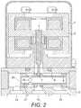
- FIG. 2is a cross-sectional view of a servovalve according to the disclosure.
- FIG. 3is a cross-sectional view of the spool of the servovalve of FIG. 2 .
- FIG. 4is a perspective view of a servovalve according to the disclosure.
- FIG. 5shows the servovalve of FIG. 3 in a fully opened position.
- FIG. 6shows the servovalve of FIG. 3 in a fully closed position.
- FIG. 7shows the servovalve of FIGS. 5 and 6 showing the forces in balance acting on the spool.
- FIG. 8is a perspective view of the servovalve assembly.
- FIG. 9is a perspective view of the servovalve assembly of FIG. 8 with the housing removed.
- a servovalvecan be used in an actuator control system.
- the servovalveis controlled by a torque motor to control a control flow of fluid that is output via e.g. a butterfly value to control the movement of an actuator.
- the preferred embodimentcomprises, in brief, a servovalve assembly having a torque motor 1 and a moveable armature 2 mounted on a torsion bridge.
- the armatureis jointed through a rigid beam 3 ending with a ball joint 7 .
- a spool 4is mounted in a supporting block 5 .
- the armature 2engages with the moveable spool 4 via the ball joint 7 . This enables rotation of the armature 2 to translate to axial movement of the spool 4 .
- the spool 4is part of a spool assembly having three ports: a supply port 14 , a control port 15 , and a return port 16 .
- the torque motormoves the armature 2 causing axial movement of the spool 4 which either blocks/occludes the passage between the supply port and the control port or opens the passage to allow flow between the two ports, depending on the axial position of the spool due to the position of the armature 2 , thus modulating pressure on the control port 15 and controlling the actuator (not shown).
- the spool 4 and the block 5form a 3-way control valve, in which supply pressure is distributed on both sides of the spool to balance forces i.e. so that there are no axial forces on the spool.
- the joint between the torque motor 1 and the supporting block 5is preferably sealed. The movement of the spool and, thus, the flow rate from the control port 15 depend on applied electric current from the motor.
- the assemblyis arranged to control an actuator based on the fluid flow from the control port 15 e.g. via a butterfly valve (see FIG. 1 ).
- the servovalvecontrols an actuator which, in turn, controls an air valve such as a butterfly valve.
- Supply pressureis provided to the servovalve housing via supply port 14 .
- the pressure at return port 16is atmospheric pressure which will vary depending e.g. on the altitude of the aircraft in flight.
- Control port 15provides a controlled pressure, dependant on the armature position and resulting spool position, to be provided to an actuator.
- the spool 4is in the form of a tubular member arranged in the block 5 to be moved axially by the armature 3 that engages with the spool 4 .
- the spoolhas, at one end, an opening 18 in fluid engagement with the supply port 14 such that fluid from the supply port enters the opening and fills the interior of the spool 4 .
- the spoolis provided with one or more apertures 19 via which fluid can exit the spool.
- the armature 3In the closed position, the armature 3 (under control of the control signal/motor) positions the spool 4 relative to the block 5 and the control port 15 such that there is no fluid flow path between the aperture(s) 19 and the control port 15 , as can be seen in FIGS. 2, 3 and 6 .
- the fluid from the supply port and inside the spool 4provides a balanced pressure acting on the spool.
- the motor 1drives the armature 3 to move the spool 4 axially (to the right in the drawings) so that the aperture(s) 19 overlap with the control port 15 to provide a fluid flow path from the supply port to the control port via the aperture(s). This can be seen in FIGS. 5 and 7 . In this position, the return port or exhaust is closed.
- Fluidcan then flow through the control port 15 to an actuator to control the position of an air valve e.g. a butterfly valve.
- an air valvee.g. a butterfly valve.
- control currentis provided to coils of the motor (here a torque motor) creating electromagnetic torque opposing the sum of mechanical and magnetic torque already ‘present’ in the torque motor 1 .
- a torque motorusually consists of coil windings, a ferromagnetic armature, permanent magnets and a mechanical spring (here two torsional bridge shafts). This arrangement ideally provides movement of some kind of member (here the armature 3 ) proportional to the input control current. Other types of motor could be envisaged.
- the motoris either non-energized or, in some embodiments drives the armature in the opposite direction, so that the orifice creating a passage for fluid flow between the supply port 14 and the control port 15 is closed off and no fluid flows.
- FIG. 6shows the spool in the closed position. In this position, the exhaust or return port 16 is open.
- FIG. 8shows a perspective view of the servovalve with the armature 3 extending into the block 5 within which the spool is mounted.
- the shape and configurationis clearly just one possible example.
- FIG. 9shows the assembly of FIG. 8 but with the block removed to show the spool 4 .
- the supply pressureis distributed on both sides of the spool to balance forces acting on the spool.
- the arrangementis, therefore, able to handle large fluid flows without requiring an increase in size of the assembly.
- the balanced pressuremeans that the spool does not need to overcome forces from pressure.
- the design of the torque motorallows for simplified calibration in embodiments in which it is detachable from the servovalve assembly.
Landscapes
- Engineering & Computer Science (AREA)
- General Engineering & Computer Science (AREA)
- Mechanical Engineering (AREA)
- Physics & Mathematics (AREA)
- Fluid Mechanics (AREA)
- Servomotors (AREA)
Abstract
Description
Claims (5)
Applications Claiming Priority (3)
| Application Number | Priority Date | Filing Date | Title |
|---|---|---|---|
| EP16461550 | 2016-08-16 | ||
| EP16461550.2AEP3284956B1 (en) | 2016-08-16 | 2016-08-16 | Servovalve |
| EP16461550.2 | 2016-08-16 |
Publications (2)
| Publication Number | Publication Date |
|---|---|
| US20180051814A1 US20180051814A1 (en) | 2018-02-22 |
| US10683943B2true US10683943B2 (en) | 2020-06-16 |
Family
ID=56694081
Family Applications (1)
| Application Number | Title | Priority Date | Filing Date |
|---|---|---|---|
| US15/591,582ActiveUS10683943B2 (en) | 2016-08-16 | 2017-05-10 | Servovalve |
Country Status (2)
| Country | Link |
|---|---|
| US (1) | US10683943B2 (en) |
| EP (1) | EP3284956B1 (en) |
Families Citing this family (3)
| Publication number | Priority date | Publication date | Assignee | Title |
|---|---|---|---|---|
| DE102018218301A1 (en)* | 2018-10-25 | 2020-04-30 | Danfoss Power Solutions Gmbh & Co. Ohg | Displacement control device |
| EP3715643B1 (en) | 2019-03-29 | 2022-03-09 | Hamilton Sundstrand Corporation | Servo valve with improved sealing and method of manufacturing the same |
| IT202000012457A1 (en)* | 2020-05-26 | 2021-11-26 | Walvoil Spa | MANUAL EMERGENCY OPERATION FOR LINEAR SLIDING VALVES |
Citations (23)
| Publication number | Priority date | Publication date | Assignee | Title |
|---|---|---|---|---|
| US2910081A (en)* | 1958-01-30 | 1959-10-27 | Hanna Engineering Works | Reciprocating valve structure |
| US3227172A (en)* | 1962-05-31 | 1966-01-04 | Davy & United Eng Co Ltd | Pressure regulating valve with balanced spring adjusting means |
| US3385309A (en)* | 1965-11-03 | 1968-05-28 | Philco Ford Corp | Fluid flow control means |
| US3550631A (en)* | 1968-06-17 | 1970-12-29 | Pneumo Dynamics Corp | Valve plunger drive mechanism |
| US3561489A (en)* | 1967-12-22 | 1971-02-09 | Contraves Ag | Hydraulically or pneumatically controllable slide valve arrangement |
| US3643699A (en)* | 1970-05-18 | 1972-02-22 | Textron Inc | Torque motor operated valve |
| US3672399A (en)* | 1971-01-07 | 1972-06-27 | Contraves Ag | Hydraulic or pneumatic controlled two stage slide valve |
| US3772889A (en)* | 1971-06-16 | 1973-11-20 | Textron Inc | Servo pump having throttled input |
| US3785216A (en)* | 1970-11-27 | 1974-01-15 | Redman Heenan Froude Ltd | Control systems for hydrokinetic devices |
| JPS527024A (en) | 1975-07-07 | 1977-01-19 | Fujikoshi Kk | Oil pressure valve |
| US4046061A (en) | 1975-12-03 | 1977-09-06 | The Garrett Corporation | Four-way clevis valve and method |
| US4193425A (en)* | 1976-08-20 | 1980-03-18 | Societe D'optique, Precision Electronique Et Mecanique-Sopelem | Electrohydraulic servo-valve |
| GB2104249A (en) | 1981-08-19 | 1983-03-02 | Moog Inc | Servovalves |
| US4553731A (en)* | 1984-09-07 | 1985-11-19 | Bethlehem Steel Corporation | Fail-closed, tight seal gas safety valve system |
| US4779648A (en)* | 1985-02-25 | 1988-10-25 | Sloate Harry M | Pilot controlled valves |
| US4793377A (en) | 1986-08-18 | 1988-12-27 | E-Systems, Inc. | Direct drive servo valve |
| US4987927A (en) | 1988-12-27 | 1991-01-29 | Sterer Engineering And Manufacturing Company | Direct-drive valve |
| US6000678A (en) | 1998-10-12 | 1999-12-14 | H.R. Textron Inc. | Motor/spool interface for direct drive servovalve |
| US20020134444A1 (en)* | 2001-03-26 | 2002-09-26 | Eiji Isobe | Solenoid valve |
| US6786238B2 (en) | 2002-06-11 | 2004-09-07 | Festo Ag & Co. | Solenoid valve |
| US20150047729A1 (en) | 2012-02-23 | 2015-02-19 | Moog Inc. | Integrated structure electro-hydraulic valve |
| US20160049230A1 (en)* | 2014-08-12 | 2016-02-18 | HS Wroclaw Sp. z o. o. | Magnetic armature |
| US9309900B2 (en) | 2012-02-09 | 2016-04-12 | Moog Inc. | Electro-hydraulic servo valve |
- 2016
- 2016-08-16EPEP16461550.2Apatent/EP3284956B1/enactiveActive
- 2017
- 2017-05-10USUS15/591,582patent/US10683943B2/enactiveActive
Patent Citations (23)
| Publication number | Priority date | Publication date | Assignee | Title |
|---|---|---|---|---|
| US2910081A (en)* | 1958-01-30 | 1959-10-27 | Hanna Engineering Works | Reciprocating valve structure |
| US3227172A (en)* | 1962-05-31 | 1966-01-04 | Davy & United Eng Co Ltd | Pressure regulating valve with balanced spring adjusting means |
| US3385309A (en)* | 1965-11-03 | 1968-05-28 | Philco Ford Corp | Fluid flow control means |
| US3561489A (en)* | 1967-12-22 | 1971-02-09 | Contraves Ag | Hydraulically or pneumatically controllable slide valve arrangement |
| US3550631A (en)* | 1968-06-17 | 1970-12-29 | Pneumo Dynamics Corp | Valve plunger drive mechanism |
| US3643699A (en)* | 1970-05-18 | 1972-02-22 | Textron Inc | Torque motor operated valve |
| US3785216A (en)* | 1970-11-27 | 1974-01-15 | Redman Heenan Froude Ltd | Control systems for hydrokinetic devices |
| US3672399A (en)* | 1971-01-07 | 1972-06-27 | Contraves Ag | Hydraulic or pneumatic controlled two stage slide valve |
| US3772889A (en)* | 1971-06-16 | 1973-11-20 | Textron Inc | Servo pump having throttled input |
| JPS527024A (en) | 1975-07-07 | 1977-01-19 | Fujikoshi Kk | Oil pressure valve |
| US4046061A (en) | 1975-12-03 | 1977-09-06 | The Garrett Corporation | Four-way clevis valve and method |
| US4193425A (en)* | 1976-08-20 | 1980-03-18 | Societe D'optique, Precision Electronique Et Mecanique-Sopelem | Electrohydraulic servo-valve |
| GB2104249A (en) | 1981-08-19 | 1983-03-02 | Moog Inc | Servovalves |
| US4553731A (en)* | 1984-09-07 | 1985-11-19 | Bethlehem Steel Corporation | Fail-closed, tight seal gas safety valve system |
| US4779648A (en)* | 1985-02-25 | 1988-10-25 | Sloate Harry M | Pilot controlled valves |
| US4793377A (en) | 1986-08-18 | 1988-12-27 | E-Systems, Inc. | Direct drive servo valve |
| US4987927A (en) | 1988-12-27 | 1991-01-29 | Sterer Engineering And Manufacturing Company | Direct-drive valve |
| US6000678A (en) | 1998-10-12 | 1999-12-14 | H.R. Textron Inc. | Motor/spool interface for direct drive servovalve |
| US20020134444A1 (en)* | 2001-03-26 | 2002-09-26 | Eiji Isobe | Solenoid valve |
| US6786238B2 (en) | 2002-06-11 | 2004-09-07 | Festo Ag & Co. | Solenoid valve |
| US9309900B2 (en) | 2012-02-09 | 2016-04-12 | Moog Inc. | Electro-hydraulic servo valve |
| US20150047729A1 (en) | 2012-02-23 | 2015-02-19 | Moog Inc. | Integrated structure electro-hydraulic valve |
| US20160049230A1 (en)* | 2014-08-12 | 2016-02-18 | HS Wroclaw Sp. z o. o. | Magnetic armature |
Non-Patent Citations (1)
| Title |
|---|
| European Search Report for Applicaiton No. 16461550.2-1754, dated Feb. 8, 2017, 5 Pages. |
Also Published As
| Publication number | Publication date |
|---|---|
| EP3284956B1 (en) | 2019-07-24 |
| EP3284956A1 (en) | 2018-02-21 |
| US20180051814A1 (en) | 2018-02-22 |
Similar Documents
| Publication | Publication Date | Title |
|---|---|---|
| US10563675B2 (en) | Servovalve | |
| US10954971B2 (en) | Servovalve | |
| US10683943B2 (en) | Servovalve | |
| US11530755B2 (en) | Servo valve | |
| US10598297B2 (en) | Servovalve | |
| EP3409952B1 (en) | Servovalve | |
| US11566722B2 (en) | Servo valve | |
| US10544870B2 (en) | Servovalve assembly | |
| US10760704B2 (en) | Servovalve assembly | |
| US20180051821A1 (en) | Servovalve | |
| US11732819B2 (en) | Servo valve | |
| EP3597937B1 (en) | Servo valve | |
| US20230366482A1 (en) | Servovalve | |
| US11408443B2 (en) | Servovalve | |
| US20230175534A1 (en) | Servo valve |
Legal Events
| Date | Code | Title | Description |
|---|---|---|---|
| AS | Assignment | Owner name:HS WROCLAW SP. Z O.O, POLAND Free format text:ASSIGNMENT OF ASSIGNORS INTEREST;ASSIGNORS:KOZLOWSKI, PIOTR;BIELEN, MICHAL;PLUCINSKI, WOJCIECH;REEL/FRAME:042393/0655 Effective date:20160829 Owner name:HAMILTON SUNDSTRAND CORPORATION, NORTH CAROLINA Free format text:ASSIGNMENT OF ASSIGNORS INTEREST;ASSIGNOR:HS WROCLAW SP. Z O.O;REEL/FRAME:042393/0677 Effective date:20161025 | |
| STPP | Information on status: patent application and granting procedure in general | Free format text:FINAL REJECTION MAILED | |
| STPP | Information on status: patent application and granting procedure in general | Free format text:RESPONSE AFTER FINAL ACTION FORWARDED TO EXAMINER | |
| STPP | Information on status: patent application and granting procedure in general | Free format text:ADVISORY ACTION MAILED | |
| STPP | Information on status: patent application and granting procedure in general | Free format text:DOCKETED NEW CASE - READY FOR EXAMINATION | |
| STPP | Information on status: patent application and granting procedure in general | Free format text:NON FINAL ACTION MAILED | |
| STPP | Information on status: patent application and granting procedure in general | Free format text:RESPONSE TO NON-FINAL OFFICE ACTION ENTERED AND FORWARDED TO EXAMINER | |
| STPP | Information on status: patent application and granting procedure in general | Free format text:NOTICE OF ALLOWANCE MAILED -- APPLICATION RECEIVED IN OFFICE OF PUBLICATIONS | |
| STPP | Information on status: patent application and granting procedure in general | Free format text:PUBLICATIONS -- ISSUE FEE PAYMENT VERIFIED | |
| STCF | Information on status: patent grant | Free format text:PATENTED CASE | |
| MAFP | Maintenance fee payment | Free format text:PAYMENT OF MAINTENANCE FEE, 4TH YEAR, LARGE ENTITY (ORIGINAL EVENT CODE: M1551); ENTITY STATUS OF PATENT OWNER: LARGE ENTITY Year of fee payment:4 |