US10682547B2 - Pull down exercise apparatus - Google Patents
Pull down exercise apparatusDownload PDFInfo
- Publication number
- US10682547B2 US10682547B2US15/986,502US201815986502AUS10682547B2US 10682547 B2US10682547 B2US 10682547B2US 201815986502 AUS201815986502 AUS 201815986502AUS 10682547 B2US10682547 B2US 10682547B2
- Authority
- US
- United States
- Prior art keywords
- user
- linear axis
- input arm
- resistance
- trunk
- Prior art date
- Legal status (The legal status is an assumption and is not a legal conclusion. Google has not performed a legal analysis and makes no representation as to the accuracy of the status listed.)
- Active, expires
Links
Images


Classifications
- A—HUMAN NECESSITIES
- A63—SPORTS; GAMES; AMUSEMENTS
- A63B—APPARATUS FOR PHYSICAL TRAINING, GYMNASTICS, SWIMMING, CLIMBING, OR FENCING; BALL GAMES; TRAINING EQUIPMENT
- A63B21/00—Exercising apparatus for developing or strengthening the muscles or joints of the body by working against a counterforce, with or without measuring devices
- A63B21/15—Arrangements for force transmissions
- A63B21/151—Using flexible elements for reciprocating movements, e.g. ropes or chains
- A63B21/154—Using flexible elements for reciprocating movements, e.g. ropes or chains using special pulley-assemblies
- A—HUMAN NECESSITIES
- A63—SPORTS; GAMES; AMUSEMENTS
- A63B—APPARATUS FOR PHYSICAL TRAINING, GYMNASTICS, SWIMMING, CLIMBING, OR FENCING; BALL GAMES; TRAINING EQUIPMENT
- A63B23/00—Exercising apparatus specially adapted for particular parts of the body
- A63B23/035—Exercising apparatus specially adapted for particular parts of the body for limbs, i.e. upper or lower limbs, e.g. simultaneously
- A63B23/03516—For both arms together or both legs together; Aspects related to the co-ordination between right and left side limbs of a user
- A63B23/03525—Supports for both feet or both hands performing simultaneously the same movement, e.g. single pedal or single handle
- A—HUMAN NECESSITIES
- A63—SPORTS; GAMES; AMUSEMENTS
- A63B—APPARATUS FOR PHYSICAL TRAINING, GYMNASTICS, SWIMMING, CLIMBING, OR FENCING; BALL GAMES; TRAINING EQUIPMENT
- A63B21/00—Exercising apparatus for developing or strengthening the muscles or joints of the body by working against a counterforce, with or without measuring devices
- A63B21/00058—Mechanical means for varying the resistance
- A63B21/00065—Mechanical means for varying the resistance by increasing or reducing the number of resistance units
- A—HUMAN NECESSITIES
- A63—SPORTS; GAMES; AMUSEMENTS
- A63B—APPARATUS FOR PHYSICAL TRAINING, GYMNASTICS, SWIMMING, CLIMBING, OR FENCING; BALL GAMES; TRAINING EQUIPMENT
- A63B21/00—Exercising apparatus for developing or strengthening the muscles or joints of the body by working against a counterforce, with or without measuring devices
- A63B21/008—Exercising apparatus for developing or strengthening the muscles or joints of the body by working against a counterforce, with or without measuring devices using hydraulic or pneumatic force-resisters
- A63B21/0083—Exercising apparatus for developing or strengthening the muscles or joints of the body by working against a counterforce, with or without measuring devices using hydraulic or pneumatic force-resisters of the piston-cylinder type
- A—HUMAN NECESSITIES
- A63—SPORTS; GAMES; AMUSEMENTS
- A63B—APPARATUS FOR PHYSICAL TRAINING, GYMNASTICS, SWIMMING, CLIMBING, OR FENCING; BALL GAMES; TRAINING EQUIPMENT
- A63B21/00—Exercising apparatus for developing or strengthening the muscles or joints of the body by working against a counterforce, with or without measuring devices
- A63B21/008—Exercising apparatus for developing or strengthening the muscles or joints of the body by working against a counterforce, with or without measuring devices using hydraulic or pneumatic force-resisters
- A63B21/0085—Exercising apparatus for developing or strengthening the muscles or joints of the body by working against a counterforce, with or without measuring devices using hydraulic or pneumatic force-resisters using pneumatic force-resisters
- A63B21/0087—Exercising apparatus for developing or strengthening the muscles or joints of the body by working against a counterforce, with or without measuring devices using hydraulic or pneumatic force-resisters using pneumatic force-resisters of the piston-cylinder type
- A—HUMAN NECESSITIES
- A63—SPORTS; GAMES; AMUSEMENTS
- A63B—APPARATUS FOR PHYSICAL TRAINING, GYMNASTICS, SWIMMING, CLIMBING, OR FENCING; BALL GAMES; TRAINING EQUIPMENT
- A63B21/00—Exercising apparatus for developing or strengthening the muscles or joints of the body by working against a counterforce, with or without measuring devices
- A63B21/02—Exercising apparatus for developing or strengthening the muscles or joints of the body by working against a counterforce, with or without measuring devices using resilient force-resisters
- A63B21/023—Wound springs
- A—HUMAN NECESSITIES
- A63—SPORTS; GAMES; AMUSEMENTS
- A63B—APPARATUS FOR PHYSICAL TRAINING, GYMNASTICS, SWIMMING, CLIMBING, OR FENCING; BALL GAMES; TRAINING EQUIPMENT
- A63B21/00—Exercising apparatus for developing or strengthening the muscles or joints of the body by working against a counterforce, with or without measuring devices
- A63B21/02—Exercising apparatus for developing or strengthening the muscles or joints of the body by working against a counterforce, with or without measuring devices using resilient force-resisters
- A63B21/04—Exercising apparatus for developing or strengthening the muscles or joints of the body by working against a counterforce, with or without measuring devices using resilient force-resisters attached to static foundation, e.g. a user
- A63B21/0407—Anchored at two end points, e.g. installed within an apparatus
- A—HUMAN NECESSITIES
- A63—SPORTS; GAMES; AMUSEMENTS
- A63B—APPARATUS FOR PHYSICAL TRAINING, GYMNASTICS, SWIMMING, CLIMBING, OR FENCING; BALL GAMES; TRAINING EQUIPMENT
- A63B21/00—Exercising apparatus for developing or strengthening the muscles or joints of the body by working against a counterforce, with or without measuring devices
- A63B21/06—User-manipulated weights
- A63B21/062—User-manipulated weights including guide for vertical or non-vertical weights or array of weights to move against gravity forces
- A63B21/0626—User-manipulated weights including guide for vertical or non-vertical weights or array of weights to move against gravity forces with substantially vertical guiding means
- A63B21/0628—User-manipulated weights including guide for vertical or non-vertical weights or array of weights to move against gravity forces with substantially vertical guiding means for vertical array of weights
- A63B21/063—Weight selecting means
- A—HUMAN NECESSITIES
- A63—SPORTS; GAMES; AMUSEMENTS
- A63B—APPARATUS FOR PHYSICAL TRAINING, GYMNASTICS, SWIMMING, CLIMBING, OR FENCING; BALL GAMES; TRAINING EQUIPMENT
- A63B21/00—Exercising apparatus for developing or strengthening the muscles or joints of the body by working against a counterforce, with or without measuring devices
- A63B21/15—Arrangements for force transmissions
- A63B21/151—Using flexible elements for reciprocating movements, e.g. ropes or chains
- A63B21/152—Bowden-type cables
- A—HUMAN NECESSITIES
- A63—SPORTS; GAMES; AMUSEMENTS
- A63B—APPARATUS FOR PHYSICAL TRAINING, GYMNASTICS, SWIMMING, CLIMBING, OR FENCING; BALL GAMES; TRAINING EQUIPMENT
- A63B21/00—Exercising apparatus for developing or strengthening the muscles or joints of the body by working against a counterforce, with or without measuring devices
- A63B21/15—Arrangements for force transmissions
- A63B21/159—Using levers for transmitting forces
- A—HUMAN NECESSITIES
- A63—SPORTS; GAMES; AMUSEMENTS
- A63B—APPARATUS FOR PHYSICAL TRAINING, GYMNASTICS, SWIMMING, CLIMBING, OR FENCING; BALL GAMES; TRAINING EQUIPMENT
- A63B21/00—Exercising apparatus for developing or strengthening the muscles or joints of the body by working against a counterforce, with or without measuring devices
- A63B21/40—Interfaces with the user related to strength training; Details thereof
- A63B21/4027—Specific exercise interfaces
- A63B21/4033—Handles, pedals, bars or platforms
- A63B21/4035—Handles, pedals, bars or platforms for operation by hand
- A—HUMAN NECESSITIES
- A63—SPORTS; GAMES; AMUSEMENTS
- A63B—APPARATUS FOR PHYSICAL TRAINING, GYMNASTICS, SWIMMING, CLIMBING, OR FENCING; BALL GAMES; TRAINING EQUIPMENT
- A63B21/00—Exercising apparatus for developing or strengthening the muscles or joints of the body by working against a counterforce, with or without measuring devices
- A63B21/40—Interfaces with the user related to strength training; Details thereof
- A63B21/4041—Interfaces with the user related to strength training; Details thereof characterised by the movements of the interface
- A63B21/4047—Pivoting movement
- A—HUMAN NECESSITIES
- A63—SPORTS; GAMES; AMUSEMENTS
- A63B—APPARATUS FOR PHYSICAL TRAINING, GYMNASTICS, SWIMMING, CLIMBING, OR FENCING; BALL GAMES; TRAINING EQUIPMENT
- A63B23/00—Exercising apparatus specially adapted for particular parts of the body
- A63B23/02—Exercising apparatus specially adapted for particular parts of the body for the abdomen, the spinal column or the torso muscles related to shoulders (e.g. chest muscles)
- A63B23/0205—Abdomen
- A63B23/0211—Abdomen moving torso with immobilized lower limbs
- A—HUMAN NECESSITIES
- A63—SPORTS; GAMES; AMUSEMENTS
- A63B—APPARATUS FOR PHYSICAL TRAINING, GYMNASTICS, SWIMMING, CLIMBING, OR FENCING; BALL GAMES; TRAINING EQUIPMENT
- A63B23/00—Exercising apparatus specially adapted for particular parts of the body
- A63B23/02—Exercising apparatus specially adapted for particular parts of the body for the abdomen, the spinal column or the torso muscles related to shoulders (e.g. chest muscles)
- A63B23/0233—Muscles of the back, e.g. by an extension of the body against a resistance, reverse crunch
- A—HUMAN NECESSITIES
- A63—SPORTS; GAMES; AMUSEMENTS
- A63B—APPARATUS FOR PHYSICAL TRAINING, GYMNASTICS, SWIMMING, CLIMBING, OR FENCING; BALL GAMES; TRAINING EQUIPMENT
- A63B23/00—Exercising apparatus specially adapted for particular parts of the body
- A63B23/035—Exercising apparatus specially adapted for particular parts of the body for limbs, i.e. upper or lower limbs, e.g. simultaneously
- A63B23/12—Exercising apparatus specially adapted for particular parts of the body for limbs, i.e. upper or lower limbs, e.g. simultaneously for upper limbs or related muscles, e.g. chest, upper back or shoulder muscles
- A63B23/1209—Involving a bending of elbow and shoulder joints simultaneously
- A—HUMAN NECESSITIES
- A63—SPORTS; GAMES; AMUSEMENTS
- A63B—APPARATUS FOR PHYSICAL TRAINING, GYMNASTICS, SWIMMING, CLIMBING, OR FENCING; BALL GAMES; TRAINING EQUIPMENT
- A63B23/00—Exercising apparatus specially adapted for particular parts of the body
- A63B23/035—Exercising apparatus specially adapted for particular parts of the body for limbs, i.e. upper or lower limbs, e.g. simultaneously
- A63B23/12—Exercising apparatus specially adapted for particular parts of the body for limbs, i.e. upper or lower limbs, e.g. simultaneously for upper limbs or related muscles, e.g. chest, upper back or shoulder muscles
- A63B23/1281—Exercising apparatus specially adapted for particular parts of the body for limbs, i.e. upper or lower limbs, e.g. simultaneously for upper limbs or related muscles, e.g. chest, upper back or shoulder muscles primarily by articulating the elbow joint
- A—HUMAN NECESSITIES
- A63—SPORTS; GAMES; AMUSEMENTS
- A63B—APPARATUS FOR PHYSICAL TRAINING, GYMNASTICS, SWIMMING, CLIMBING, OR FENCING; BALL GAMES; TRAINING EQUIPMENT
- A63B21/00—Exercising apparatus for developing or strengthening the muscles or joints of the body by working against a counterforce, with or without measuring devices
- A63B21/005—Exercising apparatus for developing or strengthening the muscles or joints of the body by working against a counterforce, with or without measuring devices using electromagnetic or electric force-resisters
- A—HUMAN NECESSITIES
- A63—SPORTS; GAMES; AMUSEMENTS
- A63B—APPARATUS FOR PHYSICAL TRAINING, GYMNASTICS, SWIMMING, CLIMBING, OR FENCING; BALL GAMES; TRAINING EQUIPMENT
- A63B21/00—Exercising apparatus for developing or strengthening the muscles or joints of the body by working against a counterforce, with or without measuring devices
- A63B21/008—Exercising apparatus for developing or strengthening the muscles or joints of the body by working against a counterforce, with or without measuring devices using hydraulic or pneumatic force-resisters
- A63B21/0085—Exercising apparatus for developing or strengthening the muscles or joints of the body by working against a counterforce, with or without measuring devices using hydraulic or pneumatic force-resisters using pneumatic force-resisters
- A63B21/0088—Exercising apparatus for developing or strengthening the muscles or joints of the body by working against a counterforce, with or without measuring devices using hydraulic or pneumatic force-resisters using pneumatic force-resisters by moving the surrounding air
- A—HUMAN NECESSITIES
- A63—SPORTS; GAMES; AMUSEMENTS
- A63B—APPARATUS FOR PHYSICAL TRAINING, GYMNASTICS, SWIMMING, CLIMBING, OR FENCING; BALL GAMES; TRAINING EQUIPMENT
- A63B21/00—Exercising apparatus for developing or strengthening the muscles or joints of the body by working against a counterforce, with or without measuring devices
- A63B21/012—Exercising apparatus for developing or strengthening the muscles or joints of the body by working against a counterforce, with or without measuring devices using frictional force-resisters
- A—HUMAN NECESSITIES
- A63—SPORTS; GAMES; AMUSEMENTS
- A63B—APPARATUS FOR PHYSICAL TRAINING, GYMNASTICS, SWIMMING, CLIMBING, OR FENCING; BALL GAMES; TRAINING EQUIPMENT
- A63B21/00—Exercising apparatus for developing or strengthening the muscles or joints of the body by working against a counterforce, with or without measuring devices
- A63B21/02—Exercising apparatus for developing or strengthening the muscles or joints of the body by working against a counterforce, with or without measuring devices using resilient force-resisters
- A63B21/055—Exercising apparatus for developing or strengthening the muscles or joints of the body by working against a counterforce, with or without measuring devices using resilient force-resisters extension element type
- A63B21/0552—Elastic ropes or bands
- A—HUMAN NECESSITIES
- A63—SPORTS; GAMES; AMUSEMENTS
- A63B—APPARATUS FOR PHYSICAL TRAINING, GYMNASTICS, SWIMMING, CLIMBING, OR FENCING; BALL GAMES; TRAINING EQUIPMENT
- A63B2208/00—Characteristics or parameters related to the user or player
- A63B2208/02—Characteristics or parameters related to the user or player posture
- A63B2208/0228—Sitting on the buttocks
- A63B2208/0233—Sitting on the buttocks in 90/90 position, like on a chair
- A—HUMAN NECESSITIES
- A63—SPORTS; GAMES; AMUSEMENTS
- A63B—APPARATUS FOR PHYSICAL TRAINING, GYMNASTICS, SWIMMING, CLIMBING, OR FENCING; BALL GAMES; TRAINING EQUIPMENT
- A63B2208/00—Characteristics or parameters related to the user or player
- A63B2208/02—Characteristics or parameters related to the user or player posture
- A63B2208/0228—Sitting on the buttocks
- A63B2208/0238—Sitting on the buttocks with stretched legs, like on a bed
Definitions
- the present inventionrelates to physical exercise machines and more particularly to an exercise apparatus that enables users to perform pull down exercise that is resisted by a resistance mechanism.
- Exercise machines for exercising latissimus dorsi musclesare known and used for directing movement of a user upper torso by forcing the user to use the user's lattisimus dorsi muscles against a weight resistance. It normally requires either three separate machines or at the very least, different accessory handles that would have to be switched to gain access to each configuration in order to fully exercise a user's lattisimus dorsi.
- the present inventionemploys a system where the user can accomplish all three training methods in one machine without any separate adjustments or accessory handle changes to move between each pattern.
- a dual axis arm configurationwhich allows for horizontal movement of the input grips as well as vertical movement of the arms, these three movements can be accomplished just by grabbing a different grip. Since each arm has three separate grips that are always attached, this requires no setup or modification.
- the userBy grabbing the outermost horizontal grips, the user is pulling both down and toward their midline. Since the secondary axis is blocked from moving toward the user midline and the primary axis is horizontal to the ground, the arm moves in a substantially vertical direction very similar to a cable based straight lat bar.
- the usergrabs the grips that are oriented forward of the users frontal plane, point away from the user and are approximately one foot apart which would be identified as a close grip handle configuration. Due to the fact that the users arms are forward of their frontal plane, it encourages a range of motion that has no horizontal component and is substantially vertical.
- the last exerciseis accomplished with the user grabbing the inner most horizontal grip. In this exercise, the users arms elbows are facing outward which encourages a divergent path of motion moving both down and away from the users midline. Since the arms secondary axis allows movement away from the midline, the divergent path is accomplished with ease. Since the resistive load is attached directly to the arm, any horizontal motion is accompanied by a significant vertical load in addition to a slight horizontal resistive component.
- the seat ( 16 ) and the input arm assembly ( 24 )are typically arranged and adapted to enable the user ( 5 ) in a user standing position (USP) to manually engage (ME) the manually graspable mechanism ( 30 h ) with the input arm assembly in the start motionless position (SMP) and to manually pull (RDF) the manually graspable mechanism ( 30 h ) downwardly (DW) under user exerted force (RDF) to a start sitting exercise position (SSEP) where the user is sitting in a seated position (SP) on the seat surface (S) and manually engaging (ME) the manually graspable mechanism ( 30 h ),
- the input arm assemblyis typically interconnected to the resistance mechanism 42 at a point of interconnection 30 de of the input arm assembly that is spaced a first selected orthogonal distance FOD apart from the first linear axis selected to create a first selected torque resistance FTR from the resistance mechanism 42 when the input arm assembly is pivoted away from the start motionless position SMP and a second selected orthogonal distance SOD from the second linear axis selected to create a second selected torque resistance STR from the resistance mechanism 42 when the input arm assembly is pivoted away from the start motionless position SMP.
- the first selected orthogonal distance FODis preferably greater than the second selected orthogonal distance SOD.
- the first selected orthogonal distance FODis preferably greater than or equal to about 6 inches and the second selected orthogonal distance SOD is greater than or equal to about 3 inches.
- the first linear axis and second linear axiscan be disposed generally orthogonal relative to each other.
- the input arm assemblycan be interconnected to the resistance mechanism via a cable that is interconnected at a proximal end to a point of interconnection of the input arm assembly that is spaced a first selected orthogonal distance apart from the first linear axis selected to create a first selected torque resistance from the resistance mechanism and a second selected orthogonal distance from the second linear axis selected to create a second selected torque resistance from the resistance mechanism wherein a distal end of the cable is interconnected to the resistance mechanism.
- the resistance mechanismcan comprise a selectable fixed weight device or a device that increases degree of resistance against the user's application of force on increase in pivotable movement of the input arm assembly rearwardly away from the start motionless position.
- the seatis preferably selectively adjustable 100 in vertical position relative to the manually graspable mechanism.
- the apparatuscan further comprise a stabilization pad mounted in a fixed position relative to the seat that is adapted to engage an anterior surface of the user's legs when the user is seated on the seat in an orientation where the longitudinal axis of the user's trunk is disposed generally upright and the anterior and posterior sides of the user's trunk are oriented generally in the forward to rearward direction.
- a stabilization padmounted in a fixed position relative to the seat that is adapted to engage an anterior surface of the user's legs when the user is seated on the seat in an orientation where the longitudinal axis of the user's trunk is disposed generally upright and the anterior and posterior sides of the user's trunk are oriented generally in the forward to rearward direction.
- the input arm assemblycan comprise an arm interconnected to a first axle that pivots about the first linear axis, the first axle being fixedly interconnected to a second axle that pivots about the second linear axis.
- the first axleis preferably adapted to rotate around the first linear axis and the second axle is non-rotatable around the second linear axis, the first and second axles being pivotably mounted to first and second brackets forming a gimbal assembly.
- the first selected orthogonal distanceis preferably greater than the second selected orthogonal distance.
- the first selected orthogonal distanceis typically greater than or equal to about 9 inches and the second selected orthogonal distance is greater than or equal to about 3 inches.
- the first linear axis and second linear axiscan be disposed generally orthogonal relative to each other.
- the input arm assemblyis preferably interconnected to the resistance mechanism via a cable that is interconnected at a proximal end to a point of interconnection of the input arm assembly that is spaced a first selected orthogonal distance apart from the first linear axis selected to create a first selected torque resistance from the resistance mechanism and a second selected orthogonal distance from the second linear axis selected to create a second selected torque resistance from the resistance mechanism wherein a distal end of the cable is interconnected to the resistance mechanism.
- the resistance mechanismcan comprise a selectable fixed weight device or a device that increases degree of resistance against the user's application of force on increase in pivotable movement of the input arm assembly rearwardly away from the start motionless position.
- the seatis preferably selectively adjustable in vertical position relative to the manually graspable mechanism.
- Such an apparatuscan further comprise a stabilization pad mounted in a fixed position relative to the seat that is adapted to engage an anterior surface of the user's legs when the user is seated on the seat in an orientation where the longitudinal axis of the user's trunk is disposed generally upright and the anterior and posterior sides of the user's trunk are oriented generally in the forward to rearward direction.
- a stabilization padmounted in a fixed position relative to the seat that is adapted to engage an anterior surface of the user's legs when the user is seated on the seat in an orientation where the longitudinal axis of the user's trunk is disposed generally upright and the anterior and posterior sides of the user's trunk are oriented generally in the forward to rearward direction.
- the input arm assemblycan comprise an arm interconnected to a first axle that pivots about the first linear axis, the first axle being fixedly interconnected to a second axle that pivots about the second linear axis.
- the first axleis preferably adapted to rotate around the first linear axis and the second axle is non-rotatable around the second linear axis, the first and second axles being pivotably mounted to first and second brackets forming a gimbal assembly.
- the manually graspable mechanismcan include two or more of a first travel director 30 ho that directs lateral travel of the manually graspable mechanism along a lateral path of travel laterally outwardly away from a midline MID of the apparatus, a second travel director 30 hs that directs lateral travel of the manually graspable mechanism along a lateral path of travel generally parallel to the midline MID and a third travel director 30 hi that directs the manually graspable mechanism along a lateral path of travel laterally inwardly toward the midline MID.
- a first travel director 30 hothat directs lateral travel of the manually graspable mechanism along a lateral path of travel laterally outwardly away from a midline MID of the apparatus
- a second travel director 30 hsthat directs lateral travel of the manually graspable mechanism along a lateral path of travel generally parallel to the midline MID
- a third travel director 30 hithat directs the manually graspable mechanism along a lateral path of travel laterally inwardly toward the midline MID.
- an apparatus for performing a pull down exercise by a usercomprising:
- the first and second linear axesare typically generally orthogonal or perpendicular to each other.
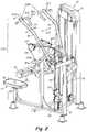
- FIG. 1is a right front perspective view of a pull down exercise apparatus according to the invention.
- FIG. 2is a rear right side perspective view of the FIG. 1 machine.
- FIG. 3is a front view of the FIG. 1 machine.
- FIG. 4is a right side view of the FIG. 1 machine.
- FIG. 5Ais a schematic front view of the FIG. 1 machine showing a user seated in a sitting exercise position.
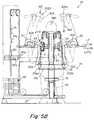
- FIG. 5Bis a schematic view similar to FIG. 5A showing the user's arms and the input arm assembly in a fully rearward and downward exercise position.
- FIG. 6Ais a schematic side view of the FIG. 5A user in a sitting exercise position.
- FIG. 6Bis a side schematic view of the FIG. 6A user in a fully rearward and downward pull down exercise position.
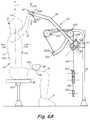
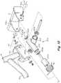
- FIG. 7is a front side perspective view of an input arm assembly of the FIG. 1 machine by itself.
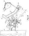
- FIG. 8is an enlarged fragmentary view of the gimbal or dual axle and bracket assembly along lines 8 - 8 of FIG. 7 .
- FIG. 9is an enlarged fragmentary view of the gimbal or dual axis and bracket assembly along arrow 9 of FIG. 7 .
- FIG. 10is an enlarged exploded fragmentary view of the dual axle and bracket or gimbal assembly by which the input arm assembly of the FIG. 1 apparatus is mounted to the frame.
- a pull down machine 10 of the present inventionincludes a support frame 12 on which a user support structure 14 is mounted.
- the user support structure 14includes a seat 16 having a surface S and a stabilization engagement pad 18 .
- the seat 16is mounted on the frame 12 facing a pair of input arms 30 having handles 30 h forwardly facing the user when seated on the seat 16 .
- the arms 30are mounted to the frame, arranged, adapted and interconnected to a weight resistance such as a weight stack 42 .
- the arms 30are adapted and mounted to the support frame 12 for pivoting in an arcuate rotation about a generally horizontal axis AA.
- the arms 30are rotatably pivotable about axis AA for arcuate generally forward (FW) to rearward (RW) and up (UW) and down (DW) movement by forcible pulling down (RDF) on the handles 30 h.
- the handles or manually graspable mechanism(s) 30 h , FIGS. 5A, 5B, 6A, 6B, 7are comprised of a first travel director 30 hi , second travel director 30 hs and third travel director 30 ho .
- Each of the travel directors 30 hi , 30 hs , 30 hoare fixedly attached to the distal end of arm 30 and each have a unique and different hand grip configuration that is selected to require the user's hands 17 , arms 13 and trunk T 1 to assume a unique and different posture when the user 5 applies a rearward downward force RDF to tend to travel along a predetermined different and unique lateral direction or path.
- Travel director 30 hiis selectively configured to require the user 5 to assume an arm, hand and trunk posture such that the user's hand 17 is forced or biased to travel laterally inwardly LATI, FIG. 3 , when the user pulls down and rearwardly RDF on the travel director 30 hi .
- Travel director 30 hois selectively configured to require the user 5 to assume an arm, hand and trunk posture such that the user's hand 17 is forced or biased to travel laterally outwardly LATO when the user pulls down and rearwardly RDF on the handle travel director 30 ho .
- Travel director 30 hsis configured to require the user 5 to assume an arm, hand and trunk posture such that the user's hand 17 is forced or biased to travel laterally generally straight LATS or generally along a parallel plane that defines the lateral midline M of the apparatus 10 when the user pulls down and rearwardly RDF on the travel director 30 hs.
- FIGS. 5A, 5Bwhen the user is engaged in an exercise cycle with the user's hands engaging and gripping ME travel director 30 ho , the user's arms, hands, shoulders and upper trunk are biased toward moving laterally outwardly LATO, FIG. 5 on pulling RDF the handle 30 h rearwardly and downwardly RDF.
- the userexerts a lateral force LF to overcome the opposing force R 1 a exerted by the weight stack 42 .
- the weight stack 42exerts the force R 1 a against the laterally outward movement LATO on account of the arrange of the point of interconnection of the distal arm 30 x at the selected point 30 de which is disposed a preselected orthogonal distance SOD from the axis of rotation Z of the arm 30 assembly 24 .
- the apparatus 10has a start motionless position SMP where the arms 30 h are stationarily disposed at a vertical position SEP above the user's trunk T 1 when the user 5 is seated SP on the seat surface S in a generally upright position where the longitudinal axis of the user 5 is generally parallel to vertical V.
- the start motionless positionis achieved by the arm 30 being either held or biased under a forwardly and upwardly directed force, typically through cables 48 , 49 and weight stack 42 , typically against the stop 160 u , FIG. 7 , such that the arm is maintained in the stationary SMP position when not subject to a force exerted on the arms 30 .
- the arm assembly 24is in the start motionless position SMP and the user stands up in a user standing position USP in order to manually reach and engage ME a selected one of the travel directors 30 ho , 30 hs , 30 hi of the handles 30 h in the start exercise position SEP.
- the user 5typically stands in the user standing position with the user's feet 9 and legs straddling the left and right sides of the seat 16 as shown in FIG. 4 .
- the user 5next begins to perform an exercise cycle by manually engaging or grabbing ME a selected one of the travel directors 30 ho , 30 hs , 30 hi which are initially disposed in the start exercise position SEP.
- the user 5exerts a generally rearwardly RW and downwardly DW directed force RDF on one or both handles 30 which causes the selected number of weight plates 42 w to exert an opposing resistance force R 1 against the user's force RDF.
- RDFresistance force
- the userthen continues to exert rearwardly and downwardly force RDF and simultaneously squat until the user 5 has lowered the user's trunk T 1 downwardly DW to a position where the user 5 is disposed in a sitting position SP on the seat surface S, FIGS. 5A-6B with the handles 30 h being disposed in the start sitting exercise position SSEP, FIGS. 5A, 5B, 6A upon the user's assuming the sitting position SP.
- the arm 30 assemblyrotates around axis AA with the cable 48 , 49 pulling the weight stack 42 upwardly and exerting a resistance force R 1 against the user's muscles which are performing the pulling RDF.
- the weight stack 42is selectively connected to one end of a cable 48 by inserting a pin 42 p in one of a plurality of holes in a lifting post 50 that passes vertically through the plates, as is well known in the art.
- the weight stack 42is formed by a stack of rectangular, brick-shaped plates 42 w .
- Each plate 42 wfurther has at least one horizontal channel or hole, wherein a pin 42 p may be disposed to slidably engage any of a series of horizontal channels which are vertically oriented on the lifting post 50 in a spaced apart manner to match the vertical spacing of the stacked weight plates 42 w .
- the pin 42 pthereby engages a portion of the stack of weight plates 42 w , such that when vertical force is applied to the lifting post 50 , the selected stack of weight plates 42 is moved upwards to create a resistance.
- the weight stack 42 apparatusis oriented such that the further down the pin is entered into the lifting post 50 , the greater the number of plates 42 w are engaged, thereby increasing the resistance of the machine.
- the weight stackis interconnected to the arm assembly 24 , 30 , 30 x by a series of pulleys 120 and cables 48 , 49 and can be interconnected by other known means such as belts, cables, chains, or tethers, so as to inhibit rotation thereof.
- the arms 30are rotatable around the U-joint or gimbal-like second axis Z which in the embodiment shown is perpendicular to axis AA although other angular relationships could be used between axis AA and axis Z.
- the usercan therefore pull RDF the arms 30 in both the back RW and forth FW arcuate direction RDA around axis AA as well as in the side-to-side SS or lateral LAT direction around axis Z.
- the degree of side-to-side SS or lateral LAT travel or pivoting around axis Z of the arms 30can be limited by stop mechanisms 150 i , 150 o which respectively limit laterally inward LATI and laterally outward LATO travel.
- the degree of upward UW and forward FW pivoting of arm 30 around axis AAis limited by stop 160 and the degree of downward DW and rearward RW pivoting around axis AA is limited by stop 160 d.
- the arms 30are interconnected via leverage arm 30 x to the weight stack 42 via cable 49 .
- Leverage arm 30 xis fixedly attached at the base 30 b of arm 30 near the pivot axis AA to provide ready leverage in pulling on the weight stack elements 42 w .
- Cable 49is connected to a distal point of connection 30 de of the leverage arms 30 x.
- the point of interconnection 30 deis selected to provide a resistance from resistance mechanism 42 to lateral LAT or side to side SS movement as well as resistance to rearward RW and downward DW movement of arm 30 .
- Point of interconnection 30 deis disposed an orthogonal distance FOD from axis AA and an orthogonal distance SOD from axis Z which together with a preselected configuration and arrangement of the arm assembly 24 and the cable 49 and other interconnections between point 30 de of arm 30 x and the weight resistance 42 to create a resistance against lateral LAT or SS movement as well as against rearward RW or downward DW movement of the handle 30 and arm assembly 24 beginning from the start motionless SMP position.
- FIG. 10shows an example of the structure of a dual axis joint or gimbal 204 by which the arms 30 , 30 x are mounted to the frame 12 .
- the dual axis jointis comprised of a first axle 202 that is mounted via bearings 202 b to bracket 30 ud for rotation RAA of arm 30 around the first axis A.
- the first axle 202is fixedly attached to second axle 200 having ball bearings 200 b mounted therein for enabling rotation RZ of arm 30 around axis Z.
- arms 30 , 30 xare mounted to axle 200 and 202 via U shaped bracket 301 .
- arms 30 , 30 xare pivotable or rotatable around both axes AA and Z.
- a stabilization spring mechanism SBis mounted around an axial spacer 200 s within the U-shaped recess of U-shaped bracket 301 in an arrangement that biases arm 30 laterally inwardly LATI to assume the start motionless position SMP when the arms 30 are not subject to an external force such as RDF.
- the stabilization pad 18is fixedly mounted and arranged relative to the seat 16 such that when the user 5 exerts a force RDF on the apparatus 10 , the user's torso T 1 is prevented from moving in an upward UW direction as a result of engagement of the anterior surface ASL of the user's legs 11 with a downwardly facing user leg engagement surface 18 s of the pad 18 .
- the seat 16 and seat surface Sare typically selectively adjustable to a selected vertical height or position via vertical height adjuster 100 such that the start exercise position of the anterior surface ASL of the user's legs 11 can be closely positioned in close adjacency or in engagement with the undersurface 18 s of the pad 18 .
Landscapes
- Health & Medical Sciences (AREA)
- Orthopedic Medicine & Surgery (AREA)
- General Health & Medical Sciences (AREA)
- Physical Education & Sports Medicine (AREA)
- Life Sciences & Earth Sciences (AREA)
- Biophysics (AREA)
- Biomedical Technology (AREA)
- Engineering & Computer Science (AREA)
- Neurology (AREA)
- Pulmonology (AREA)
- Electromagnetism (AREA)
- Physics & Mathematics (AREA)
- Rehabilitation Tools (AREA)
- Special Chairs (AREA)
Abstract
Description
- a
frame 12, - a
seat 16 having a seating surface S, - an input arm assembly (24) interconnected to a resistance mechanism (42) and a manually graspable mechanism (30h), the input arm assembly being pivotably (AA, Z) mounted on the frame for back and forth travel along a generally forward (FW) to rearward (RW) direction, the input arm assembly being adapted to reside in a start motionless position (SMP) that disposes the manually graspable mechanism (30h) in a start exercise position (SEP) that is disposed vertically (V) above the user's trunk (T1) when the user is seated on the seating surface (S) in an orientation where the longitudinal axis (LA) of the user's trunk (T1) is disposed generally upright (V),
- the input arm assembly being rotatably pivotable (RDA) around a first linear axis (AA) starting from the start motionless position (SMP) through a generally rearward (RW) and downward (DW) path of travel under resistance (R1) exerted by the resistance mechanism (42) on application of rearwardly or downwardly directed force (RDF) by the user on the manually graspable mechanism (30h),
- the input arm assembly being rotatably pivotable SS around a second linear axis Z through a generally lateral LAT or side to side path of travel under resistance R1aexerted by the
resistance mechanism 42 on application of generally laterally directed force LF by the user on the manuallygraspable mechanism 30hstarting from the start exercise position SEP.
- a
- a user being seated on the seat of the exercise apparatus described immediately above in a disposition where the longitudinal axis of the user's trunk is disposed generally upright and the anterior and posterior sides of the user's trunk are oriented generally in the forward to rearward direction,
- the user manually engaging the manually graspable mechanism, and
- the user applying a rearwardly or downwardly directed force on the manually graspable mechanism against resistance from the resistance mechanism.
- a user being seated on the seat of the exercise apparatus described above in a disposition where the longitudinal axis of the user's trunk is disposed generally upright and the anterior and posterior sides of the user's trunk are oriented generally in the forward to rearward direction,
- the user manually engaging the manually graspable mechanism of the apparatus, and
- the user applying a laterally or side to side directed force on the manually graspable mechanism against resistance from the resistance mechanism.
- a frame,
- a seat having a seating surface (PS),
- an input arm assembly interconnected to a resistance mechanism and a manually graspable mechanism, the input arm assembly being pivotably mounted on the frame for back and forth travel along a generally forward to rearward direction, the input arm assembly being adapted to reside in a start motionless position (SMP) that disposes the manually graspable mechanism (30h) in a start exercise position (SEP) that is disposed vertically above the user's trunk (T1) when the user is seated (SP) on the seating surface (S) where the longitudinal axis (LA) of the user's trunk is disposed generally upright (V),
- the input arm assembly being rotatably pivotable around a first linear axis (AA) starting from the start motionless position (SMP) through a generally rearward or downward path of travel under exertion of rearwardly or downwardly directed force RDF by the user on the manually
graspable mechanism 30h, - the input arm assembly being rotatably pivotable around a second linear axis Z through a generally lateral or side to side SS path of travel that is generally orthogonal to the rearward downward path of travel under resistance (R1a) from the resistance mechanism (42),
- the input arm assembly being interconnected to the resistance mechanism (42) at a point of interconnection (30de) of the input arm assembly that is spaced a first selected orthogonal distance (FOD) apart from the first linear axis (AA) selected to create a first selected torque resistance from the resistance mechanism (42) on pivoting of the input arm assembly around the first linear axis,
- the point of interconnection (30de) of the input arm assembly being spaced a second selected orthogonal distance (SOD) from the second linear axis selected to create a second selected torque resistance from the resistance mechanism (42) on pivoting of the input arm assembly around the second linear axis (Z).
- a user being seated on the seat of the exercise apparatus described immediately above in a disposition where the longitudinal axis of the user's trunk is disposed generally upright and the anterior and posterior sides of the user's trunk are oriented generally in the forward to rearward direction,
- the user manually engaging the manually graspable mechanism of the apparatus, and
- the user applying rearwardly and downwardly directed force on the manually graspable mechanism against resistance from the resistance mechanism.
- a user being seated on the seat of the exercise apparatus described above in a disposition where the longitudinal axis of the user's trunk is disposed generally upright and the anterior and posterior sides of the user's trunk are oriented generally in the forward to rearward direction,
- the user manually engaging the manually graspable mechanism of the apparatus, and
- the user applying a laterally or side to side directed force on the manually graspable mechanism against resistance from the resistance mechanism.
- a
frame 12, - a
seat 16 having a seating surface S, - an
input arm assembly 24 interconnected to aresistance mechanism 42 and a manuallygraspable mechanism 30h, the input arm assembly being pivotably AA, Z mounted on the frame for back and forth travel along a generally forward FW to rearward RW direction, the input arm assembly being adapted to reside in a start motionless position SMP that disposes the manuallygraspable mechanism 30hin a start exercise position SEP that is disposed vertically V above the user's trunk T1 when the user is seated SP on the seating surface S in an orientation where the longitudinal axis LA of the user's trunk T1 is disposed generally upright V, - the
seat 16 being arranged relative to theinput arm assembly 24 to position theuser 5 in a user start position USP that enables the user to manually engage ME the manuallygraspable mechanism 30hwhen the user is seated in an orientation where the longitudinal axis LA of the user's trunk T1 is disposed generally upright V and the anterior AS and posterior PS sides of the user's trunk T1 are oriented generally in the forward FW to rearward RW direction, - the input arm assembly being rotatably pivotable RDA around a first linear axis AA starting from the start exercise position SEP through a generally rearward RW and downward DW path of travel under resistance R1 exerted by the
resistance mechanism 42 on application of rearwardly or downwardly directed force RDF by the user on the manuallygraspable mechanism 30h, - the input arm assembly being rotatably pivotable SS around a second linear axis Z through a generally lateral LAT or side to side path of travel on application of generally laterally directed force LF by the user on the manually
graspable mechanism 30hstarting from the start exercise position SEP, - the manually
graspable mechanism 30hincluding at least twotravel directors 30hi,30hs,30hothat are each separately manually graspable by the user in a physical posture that is unique to each travel director, each travel director being interconnected to the input arm assembly in an arrangement that directs side to side or lateral travel of the manually graspable mechanism on application of rearwardly or downwardly directed force by the user along a lateral path of travel that is different for and unique to each travel director.
- a
- a user being seated on the seat of the exercise apparatus described above in a disposition where the longitudinal axis of the user's trunk is disposed generally upright and the anterior and posterior sides of the user's trunk are oriented generally in the forward to rearward direction,
- the user manually engaging one of the travel directors and,
- the user applying rearwardly and downwardly directed force on the manually graspable mechanism against resistance from the resistance mechanism.
- a frame,
- a seat mounted on the frame in a position relative to the ground such that a user can sit on the seat with the user's feet touching the ground,
- an input arm assembly having a pair of arms having manually engageable grips or handles, the arms being mounted, arranged and adapted such that the grips or handles are disposed above the user's head within arms-length reach of the user's hands,
- the arms being interconnected to a manually selectively adjustable weight resistance mechanism,
- the arms being adapted, mounted and arranged on the frame for being rotatably pivotable around a first linear axis by the user's pulling downwardly on the grips or handles,
- the arms being further adapted, mounted and arranged on the frame for being rotatably pivotable around a second linear axis by the user's pulling or pushing laterally or sideways on the grips or handles,
- the seat being mounted, arranged and adapted to position the user in a position while sitting on the seat such that user can readily engage the grips or handles.
Claims (16)
Priority Applications (1)
| Application Number | Priority Date | Filing Date | Title |
|---|---|---|---|
| US15/986,502US10682547B2 (en) | 2014-03-11 | 2018-05-22 | Pull down exercise apparatus |
Applications Claiming Priority (9)
| Application Number | Priority Date | Filing Date | Title |
|---|---|---|---|
| US201461951046P | 2014-03-11 | 2014-03-11 | |
| US201461951026P | 2014-03-11 | 2014-03-11 | |
| US201461951011P | 2014-03-11 | 2014-03-11 | |
| US201461951059P | 2014-03-11 | 2014-03-11 | |
| US201461951034P | 2014-03-11 | 2014-03-11 | |
| PCT/US2015/019841WO2015138538A1 (en) | 2014-03-11 | 2015-03-11 | Pull down exercise apparatus |
| US14/989,145US9981155B2 (en) | 2014-03-11 | 2016-01-06 | Pull down exercise apparatus |
| US15/654,767US10004935B2 (en) | 2014-03-11 | 2017-07-20 | Pull down exercise apparatus |
| US15/986,502US10682547B2 (en) | 2014-03-11 | 2018-05-22 | Pull down exercise apparatus |
Related Parent Applications (1)
| Application Number | Title | Priority Date | Filing Date |
|---|---|---|---|
| US15/654,767ContinuationUS10004935B2 (en) | 2014-03-11 | 2017-07-20 | Pull down exercise apparatus |
Publications (2)
| Publication Number | Publication Date |
|---|---|
| US20180264309A1 US20180264309A1 (en) | 2018-09-20 |
| US10682547B2true US10682547B2 (en) | 2020-06-16 |
Family
ID=52697580
Family Applications (10)
| Application Number | Title | Priority Date | Filing Date |
|---|---|---|---|
| US14/989,145ActiveUS9981155B2 (en) | 2014-03-11 | 2016-01-06 | Pull down exercise apparatus |
| US14/989,166Active2035-04-24US9707432B2 (en) | 2014-03-11 | 2016-01-06 | Back extension exercise apparatus |
| US14/989,123Expired - Fee RelatedUS9662531B2 (en) | 2014-03-11 | 2016-01-06 | Arm curl exercise apparatus |
| US14/995,513Expired - Fee RelatedUS10052514B2 (en) | 2014-03-11 | 2016-01-14 | Abdominal exercise apparatus |
| US14/995,502ActiveUS9999799B2 (en) | 2014-03-11 | 2016-01-14 | Arm extension exercise apparatus |
| US15/489,298Expired - Fee RelatedUS10357680B2 (en) | 2014-03-11 | 2017-04-17 | Arm curl exercise apparatus |
| US15/654,767ActiveUS10004935B2 (en) | 2014-03-11 | 2017-07-20 | Pull down exercise apparatus |
| US15/905,921Expired - Fee RelatedUS10449408B2 (en) | 2014-03-11 | 2018-02-27 | Arm extension exercise apparatus |
| US15/986,502Active2035-06-16US10682547B2 (en) | 2014-03-11 | 2018-05-22 | Pull down exercise apparatus |
| US16/042,112ActiveUS10322310B2 (en) | 2014-03-11 | 2018-07-23 | Abdominal exercise apparatus |
Family Applications Before (8)
| Application Number | Title | Priority Date | Filing Date |
|---|---|---|---|
| US14/989,145ActiveUS9981155B2 (en) | 2014-03-11 | 2016-01-06 | Pull down exercise apparatus |
| US14/989,166Active2035-04-24US9707432B2 (en) | 2014-03-11 | 2016-01-06 | Back extension exercise apparatus |
| US14/989,123Expired - Fee RelatedUS9662531B2 (en) | 2014-03-11 | 2016-01-06 | Arm curl exercise apparatus |
| US14/995,513Expired - Fee RelatedUS10052514B2 (en) | 2014-03-11 | 2016-01-14 | Abdominal exercise apparatus |
| US14/995,502ActiveUS9999799B2 (en) | 2014-03-11 | 2016-01-14 | Arm extension exercise apparatus |
| US15/489,298Expired - Fee RelatedUS10357680B2 (en) | 2014-03-11 | 2017-04-17 | Arm curl exercise apparatus |
| US15/654,767ActiveUS10004935B2 (en) | 2014-03-11 | 2017-07-20 | Pull down exercise apparatus |
| US15/905,921Expired - Fee RelatedUS10449408B2 (en) | 2014-03-11 | 2018-02-27 | Arm extension exercise apparatus |
Family Applications After (1)
| Application Number | Title | Priority Date | Filing Date |
|---|---|---|---|
| US16/042,112ActiveUS10322310B2 (en) | 2014-03-11 | 2018-07-23 | Abdominal exercise apparatus |
Country Status (4)
| Country | Link |
|---|---|
| US (10) | US9981155B2 (en) |
| EP (8) | EP3116610B1 (en) |
| CN (5) | CN106457016A (en) |
| WO (5) | WO2015138546A1 (en) |
Families Citing this family (24)
| Publication number | Priority date | Publication date | Assignee | Title |
|---|---|---|---|---|
| US10166435B2 (en) | 2014-03-11 | 2019-01-01 | Cybex International, Inc. | Back extension exercise apparatus |
| WO2015138546A1 (en)* | 2014-03-11 | 2015-09-17 | Cybex International, Inc. | Arm extension exercise apparatus |
| US10391351B2 (en)* | 2014-09-24 | 2019-08-27 | Tuffstuff Fitness International, Inc. | Functional training equipment with multiple movement planes for biceps curl exercise |
| US11305153B2 (en) | 2014-11-07 | 2022-04-19 | Fitness Cubed Inc. | Portable elliptical exercise machine and transport mechanism |
| US10569124B2 (en)* | 2014-11-07 | 2020-02-25 | Fitness Cubed Inc. | Portable elliptical exercise machine, resistance band extension, and transport mechanism |
| US9919179B2 (en)* | 2015-03-25 | 2018-03-20 | Jesus Nevarez, JR. | Exercise device |
| US9770621B2 (en)* | 2015-12-02 | 2017-09-26 | Anthony A. Zannini | Exercise device and associated methods |
| RU2643597C2 (en)* | 2016-03-15 | 2018-02-02 | Наиль Маратович Нургалиев | Training device for broadest muscle of back (latissimus) |
| TWI597088B (en)* | 2017-01-19 | 2017-09-01 | 林沛達 | Athletic Equipment |
| CN106730584A (en)* | 2017-03-17 | 2017-05-31 | 尤春蕊 | Folder chest, horizontal sliding fitness equipment |
| CA3063130A1 (en) | 2017-05-12 | 2018-11-15 | Kormel LLC | Exercise apparatus for performing a gluteal bridge movement |
| CN111867686A (en)* | 2018-03-19 | 2020-10-30 | 豪埃斯特健康体系股份有限公司 | Turning and gripping handle system for a side pull-down exercise machine |
| US10933279B1 (en)* | 2019-05-10 | 2021-03-02 | Robert Sallie | Sit-up exercise machine |
| USD995666S1 (en) | 2020-08-27 | 2023-08-15 | Rudolfo Juarez | Shoulder injury prevention device |
| CN111939525B (en)* | 2020-09-01 | 2024-12-31 | 广州一康医疗设备实业有限公司 | Isokinetic muscle strength training system and control method thereof |
| KR102225269B1 (en)* | 2020-10-13 | 2021-03-09 | (주)뉴텍웰니스 | Arm curl fitness apparatus |
| WO2022104312A1 (en) | 2020-11-12 | 2022-05-19 | Proteus Motion Inc. | Exercise handle |
| CN112674987A (en)* | 2020-12-28 | 2021-04-20 | 吉林大学 | Device is tempered in activity of cardiovascular disease patient's low limbs |
| USD986354S1 (en)* | 2021-02-12 | 2023-05-16 | Kompan /VS | Part of a training apparatus |
| CN114028777B (en)* | 2021-11-22 | 2022-08-02 | 河南科技大学第二附属医院 | Muscle rehabilitation training device for neurology disease patients |
| CN114082137B (en)* | 2021-12-10 | 2023-03-17 | 阳光经销商公司 | Comprehensive training device |
| USD1020941S1 (en)* | 2022-06-09 | 2024-04-02 | Expectations, LLC | Lap pad for exercise apparatus |
| USD1022086S1 (en)* | 2022-06-09 | 2024-04-09 | Expectations, LLC | Lap pad assembly for exercise apparatus |
| USD1022087S1 (en)* | 2022-06-09 | 2024-04-09 | Expectations, LLC | Lap pad for inversion apparatus |
Citations (44)
| Publication number | Priority date | Publication date | Assignee | Title |
|---|---|---|---|---|
| FR2174414A5 (en) | 1972-03-03 | 1973-10-12 | Vinel Pierre | |
| US4227689A (en) | 1978-07-24 | 1980-10-14 | Kintron, Incorporated | Exercising device including linkage for control of muscular exertion required through exercising stroke |
| US4725054A (en) | 1985-11-27 | 1988-02-16 | Lumex, Inc. | Low inertia counterbalance mechanism |
| US4842266A (en) | 1986-08-27 | 1989-06-27 | Sweeney Sr James S | Physical exercise apparatus having motivational display |
| US5114388A (en) | 1991-07-26 | 1992-05-19 | True Fitness Technology, Inc. | Stair simulator exerciser with adjustable incline |
| US5254066A (en) | 1991-03-13 | 1993-10-19 | Motivator, Inc. | User force application device for an exercise, physical therapy, or rehabilitation apparatus |
| WO1996026766A1 (en) | 1995-03-01 | 1996-09-06 | Cybex International Inc | Lat pulldown exercise machine and method of exercise |
| US5597375A (en) | 1995-03-01 | 1997-01-28 | Simonson; Roy | Lat pulldown exercise machine and method of exercise |
| US5913752A (en) | 1998-01-07 | 1999-06-22 | Bolf; James W. | Total body exercise machine |
| US6071216A (en) | 1996-09-30 | 2000-06-06 | Cybex International, Inc. | Pull down apparatus for exercising regions of the upper body |
| US6142917A (en) | 1996-09-30 | 2000-11-07 | Cybex International, Inc. | Chest press apparatus for exercising regions of the upper body |
| US6254516B1 (en) | 1997-09-30 | 2001-07-03 | Cybex International, Inc. | Shoulder press apparatus for exercising regions of the upper body |
| US6287243B1 (en) | 1999-02-22 | 2001-09-11 | Brunswick Corporation | Multi-adjustable exercise bench |
| US6302833B1 (en) | 2000-01-31 | 2001-10-16 | Northland Industries, Inc. | Multi-function exercise machine |
| US20020022556A1 (en) | 2000-06-26 | 2002-02-21 | Christer Eriksson | Machine for muscular training |
| US20020052268A1 (en) | 2000-05-03 | 2002-05-02 | Vicente Morcillo-Quintero | Exercise machine providing for natural movement |
| US20020198087A1 (en) | 2001-06-20 | 2002-12-26 | Gary Mitchell | Triceps extension machine |
| US6500106B1 (en) | 1996-06-21 | 2002-12-31 | Kent Fulks | Method and apparatus for mechanical emulation of dumbbells |
| US20030092543A1 (en) | 2001-11-13 | 2003-05-15 | Cybex International, Inc. | Upper torso exercise machine |
| US20030158019A1 (en) | 2001-11-13 | 2003-08-21 | Raymond Giannelli | Upper torso exercise machine |
| US20030171195A1 (en) | 2002-03-04 | 2003-09-11 | Raymond Giannelli | Arm extension machine |
| USD486535S1 (en) | 2002-11-13 | 2004-02-10 | Cybex International, Inc. | Abdominal exercise machine |
| USD490127S1 (en) | 2002-11-13 | 2004-05-18 | Cybex International, Inc. | Arm extension machine |
| US20050032614A1 (en) | 2003-06-27 | 2005-02-10 | Keiser Dennis L. | Adjustable bench |
| US20060116253A1 (en) | 2004-11-24 | 2006-06-01 | Nash Nizam | Total body strengthening and toning workstation and method of using same |
| US20060211549A1 (en) | 2005-03-18 | 2006-09-21 | Nohejl Russell J | Abdominal exercise and training apparatus |
| US20060270531A1 (en) | 2001-11-13 | 2006-11-30 | Cybex International, Inc. | Torso exercise machine |
| US20070238589A1 (en) | 2001-01-30 | 2007-10-11 | Webber Randall T | Exercise arm apparatus with pivotal linkage system |
| WO2008017049A2 (en) | 2006-08-02 | 2008-02-07 | Icon Ip Inc. | Exercise device with pivoting assembly |
| US7364535B1 (en) | 2006-02-24 | 2008-04-29 | Brunswick Corporation | Exercise apparatus with zero clearance roller seat carriage |
| KR100834880B1 (en) | 2007-06-26 | 2008-06-03 | 한라대학교산학협력단 | AB training control device |
| US20100009818A1 (en)* | 2008-07-09 | 2010-01-14 | Tom Simonson | Multi Axes Exercise Apparatus |
| US20100019128A1 (en) | 2008-07-23 | 2010-01-28 | Princeton Lightwave, Inc. | Focal Plane Array Imager |
| US20100105530A1 (en) | 2008-10-27 | 2010-04-29 | Senoh Kabushiki Kaisha | Training Apparatus |
| US7717836B1 (en) | 2007-05-15 | 2010-05-18 | Brunswick Corporation | Exercise apparatus with seat stow-away system |
| US7753830B1 (en) | 2008-05-27 | 2010-07-13 | Brunswick Corporation | Exercise equipment with dock-and-lock and spotter platform |
| US20100190617A1 (en) | 2003-01-21 | 2010-07-29 | Kenneth Bryan Gautier | Multi-axis resistance exercise devices and systems |
| US8025609B2 (en) | 2001-11-13 | 2011-09-27 | Cybex International, Inc. | Cross trainer exercise apparatus |
| US20110301002A1 (en) | 2010-06-08 | 2011-12-08 | Scott Sebastian | Abdominal exercise and training apparatus |
| US20120032262A1 (en) | 2010-08-05 | 2012-02-09 | Laas-Cnrs | Enhanced hvpmos |
| JP3183390U (en) | 2012-03-13 | 2013-05-16 | ウ−ゴン ツァン | Step machine structure |
| US8734304B2 (en) | 2010-03-04 | 2014-05-27 | Hoist Fitness Systems, Inc. | Low back exercise machine with rocking user support |
| US20170232292A1 (en) | 2014-03-11 | 2017-08-17 | Cybex International,Inc. | Back extension exercise apparatus |
| US9981155B2 (en)* | 2014-03-11 | 2018-05-29 | Cybex International, Inc. | Pull down exercise apparatus |
Family Cites Families (40)
| Publication number | Priority date | Publication date | Assignee | Title |
|---|---|---|---|---|
| US490127A (en) | 1893-01-17 | Type-writer cabinet | ||
| US486535A (en) | 1892-11-22 | Seph monier | ||
| US6746385B1 (en)* | 1993-12-20 | 2004-06-08 | Nautilus, Inc. | Upper body exercise machine |
| US5683334A (en)* | 1995-01-18 | 1997-11-04 | Webber; Randall T. | Exercise apparatus with multi-exercise press station |
| GB9503230D0 (en) | 1995-02-18 | 1995-04-05 | Bank Of England | Manufacture of printing plates by photo-ablation |
| JP3183390B2 (en) | 1995-09-05 | 2001-07-09 | キヤノン株式会社 | Photoelectric conversion device and imaging device using the same |
| US5897467A (en)* | 1997-05-29 | 1999-04-27 | Precor Incorporated | Articulated upper arm exerciser |
| JP3228216B2 (en) | 1998-03-05 | 2001-11-12 | ヤマハ株式会社 | Card game system |
| US7563214B2 (en)* | 2000-02-29 | 2009-07-21 | Hoist Fitness Systems, Inc. | Exercise arm assembly for exercise machine |
| US6743158B2 (en) | 2000-03-01 | 2004-06-01 | Cybex Interational, Inc. | Leg press |
| US7608024B2 (en) | 2000-03-06 | 2009-10-27 | Cybex International, Inc. | Multiple exercise apparatus having an adjustable arm mechanism |
| US7804044B2 (en) | 2000-12-23 | 2010-09-28 | Braincom Ag | Heating device and method for the production thereof and heatable object and method for producing same |
| US6746378B2 (en)* | 2001-06-08 | 2004-06-08 | Nautilus Human Performance Systems, Inc. | Lat pulldown weight training machine |
| US6659919B2 (en)* | 2001-06-27 | 2003-12-09 | James A. Deola | Leg exerciser |
| CA2411657C (en) | 2001-11-13 | 2009-05-19 | Cybex International, Inc. | Exercise device for cross training |
| US7537552B2 (en)* | 2003-08-25 | 2009-05-26 | Icon Ip, Inc. (State Of Delaware) | Exercise device with centrally mounted resistance rod and automatic weight selector apparatus |
| US7794371B2 (en)* | 2003-08-04 | 2010-09-14 | Hoist Fitness Systems, Inc. | Lat exercise machine with self-aligning pivoting user support |
| US7594880B2 (en)* | 2003-08-04 | 2009-09-29 | Hoist Fitness Systems, Inc. | Self-aligning pivoting seat exercise machine |
| US7654940B2 (en)* | 2006-09-06 | 2010-02-02 | Hoist Fitness Systems, Inc. | Arm exercise machine with self-aligning pivoting user support |
| US7563209B2 (en)* | 2006-09-05 | 2009-07-21 | Hoist Fitness Systems, Inc. | Leg exercise machine with self-aligning pivoting seat |
| US7993251B1 (en)* | 2003-08-04 | 2011-08-09 | Hoist Fitness Systems, Inc. | Pectoral fly exercise machine |
| US7901335B2 (en)* | 2003-08-04 | 2011-03-08 | Hoist Fitness Systems, Inc. | Multi-station exercise machine |
| US7331911B2 (en)* | 2003-11-03 | 2008-02-19 | Hoist Fitness Systems | Shoulder press exercise machine |
| US20100105533A1 (en) | 2005-03-18 | 2010-04-29 | Nohejl Russell J | Abdominal exercise and training apparatus |
| GB2442168B (en)* | 2005-06-28 | 2010-05-26 | Octane Fitness Llc | Exercise equipment with convergent hand grips |
| CN2817911Y (en)* | 2005-07-28 | 2006-09-20 | 乔山健康科技股份有限公司 | Sports equipment for a variety of sports |
| CN2838677Y (en)* | 2005-10-31 | 2006-11-22 | 青岛英派斯(集团)有限公司 | Universal pulling handle mechanism for body-building machine |
| US7670269B2 (en)* | 2006-09-05 | 2010-03-02 | Hoist Fitness Systems, Inc. | Chest press exercise machine with self-aligning pivoting user support |
| US7955234B1 (en)* | 2007-02-28 | 2011-06-07 | Pursley Michael G | Exercise device and method |
| EP2155340B1 (en) | 2007-12-21 | 2011-07-20 | Cybex International, Inc. | Exercise apparatus and method with selectively variable stabilization |
| US7938760B1 (en)* | 2008-10-17 | 2011-05-10 | Hoist Fitness Systems, Inc. | Exercise machine with lifting arm |
| USD613350S1 (en)* | 2009-03-03 | 2010-04-06 | Johnson Health Tech Co., Ltd. | Exercise apparatus |
| USD612437S1 (en)* | 2009-03-03 | 2010-03-23 | Johnson Health Tech Co., Ltd. | Exercise apparatus |
| US8007405B2 (en)* | 2009-10-12 | 2011-08-30 | Madonna Rehabilitation Hospital | Rehabilitation and exercise machine |
| CN102039022A (en)* | 2009-10-26 | 2011-05-04 | 厦门钢宇工业有限公司 | Multifunctional exercise equipment |
| CN201871160U (en)* | 2010-01-11 | 2011-06-22 | 王春龙 | Multi-functional exercise machine |
| US8113996B1 (en)* | 2010-02-12 | 2012-02-14 | Tad Allen | Dual action recumbent exercise cycle |
| CN201783145U (en)* | 2010-07-21 | 2011-04-06 | 四川阳光文化企业有限责任公司 | Seated press pull-down trainer |
| NL2008524C2 (en)* | 2012-03-22 | 2013-09-25 | Origene Group B V | Device for exercising a person's back and neck. |
| CN203154705U (en)* | 2013-03-28 | 2013-08-28 | 杨洪良 | Household power-type body builder |
- 2015
- 2015-03-11WOPCT/US2015/019855patent/WO2015138546A1/enactiveApplication Filing
- 2015-03-11EPEP15711999.1Apatent/EP3116610B1/ennot_activeNot-in-force
- 2015-03-11CNCN201580024848.0Apatent/CN106457016A/enactivePending
- 2015-03-11EPEP15711400.0Apatent/EP3116603B1/enactiveActive
- 2015-03-11EPEP15712000.7Apatent/EP3116604B1/enactiveActive
- 2015-03-11WOPCT/US2015/019837patent/WO2015138536A1/enactiveApplication Filing
- 2015-03-11WOPCT/US2015/019848patent/WO2015138541A1/enactiveApplication Filing
- 2015-03-11CNCN201580024620.1Apatent/CN106457025A/enactivePending
- 2015-03-11EPEP17181243.1Apatent/EP3257556B1/ennot_activeNot-in-force
- 2015-03-11EPEP15715524.3Apatent/EP3116612B1/enactiveActive
- 2015-03-11CNCN201580024592.3Apatent/CN106457024A/enactivePending
- 2015-03-11EPEP17201801.2Apatent/EP3326701B1/ennot_activeNot-in-force
- 2015-03-11EPEP15713075.8Apatent/EP3116611B1/ennot_activeNot-in-force
- 2015-03-11EPEP17201798.0Apatent/EP3326700B1/ennot_activeNot-in-force
- 2015-03-11WOPCT/US2015/019841patent/WO2015138538A1/enactiveApplication Filing
- 2015-03-11CNCN201580024618.4Apatent/CN106457015A/enactivePending
- 2015-03-11WOPCT/US2015/019866patent/WO2015138550A1/enactiveApplication Filing
- 2015-03-11CNCN201580024571.1Apatent/CN106457023A/enactivePending
- 2016
- 2016-01-06USUS14/989,145patent/US9981155B2/enactiveActive
- 2016-01-06USUS14/989,166patent/US9707432B2/enactiveActive
- 2016-01-06USUS14/989,123patent/US9662531B2/ennot_activeExpired - Fee Related
- 2016-01-14USUS14/995,513patent/US10052514B2/ennot_activeExpired - Fee Related
- 2016-01-14USUS14/995,502patent/US9999799B2/enactiveActive
- 2017
- 2017-04-17USUS15/489,298patent/US10357680B2/ennot_activeExpired - Fee Related
- 2017-07-20USUS15/654,767patent/US10004935B2/enactiveActive
- 2018
- 2018-02-27USUS15/905,921patent/US10449408B2/ennot_activeExpired - Fee Related
- 2018-05-22USUS15/986,502patent/US10682547B2/enactiveActive
- 2018-07-23USUS16/042,112patent/US10322310B2/enactiveActive
Patent Citations (52)
| Publication number | Priority date | Publication date | Assignee | Title |
|---|---|---|---|---|
| FR2174414A5 (en) | 1972-03-03 | 1973-10-12 | Vinel Pierre | |
| US4227689A (en) | 1978-07-24 | 1980-10-14 | Kintron, Incorporated | Exercising device including linkage for control of muscular exertion required through exercising stroke |
| US4725054A (en) | 1985-11-27 | 1988-02-16 | Lumex, Inc. | Low inertia counterbalance mechanism |
| US4842266A (en) | 1986-08-27 | 1989-06-27 | Sweeney Sr James S | Physical exercise apparatus having motivational display |
| US5254066A (en) | 1991-03-13 | 1993-10-19 | Motivator, Inc. | User force application device for an exercise, physical therapy, or rehabilitation apparatus |
| US5114388A (en) | 1991-07-26 | 1992-05-19 | True Fitness Technology, Inc. | Stair simulator exerciser with adjustable incline |
| WO1996026766A1 (en) | 1995-03-01 | 1996-09-06 | Cybex International Inc | Lat pulldown exercise machine and method of exercise |
| US5597375A (en) | 1995-03-01 | 1997-01-28 | Simonson; Roy | Lat pulldown exercise machine and method of exercise |
| US6500106B1 (en) | 1996-06-21 | 2002-12-31 | Kent Fulks | Method and apparatus for mechanical emulation of dumbbells |
| US6071216A (en) | 1996-09-30 | 2000-06-06 | Cybex International, Inc. | Pull down apparatus for exercising regions of the upper body |
| US6142917A (en) | 1996-09-30 | 2000-11-07 | Cybex International, Inc. | Chest press apparatus for exercising regions of the upper body |
| US6254516B1 (en) | 1997-09-30 | 2001-07-03 | Cybex International, Inc. | Shoulder press apparatus for exercising regions of the upper body |
| US5913752A (en) | 1998-01-07 | 1999-06-22 | Bolf; James W. | Total body exercise machine |
| US6287243B1 (en) | 1999-02-22 | 2001-09-11 | Brunswick Corporation | Multi-adjustable exercise bench |
| US6302833B1 (en) | 2000-01-31 | 2001-10-16 | Northland Industries, Inc. | Multi-function exercise machine |
| US20020052268A1 (en) | 2000-05-03 | 2002-05-02 | Vicente Morcillo-Quintero | Exercise machine providing for natural movement |
| US20020022556A1 (en) | 2000-06-26 | 2002-02-21 | Christer Eriksson | Machine for muscular training |
| US20070238589A1 (en) | 2001-01-30 | 2007-10-11 | Webber Randall T | Exercise arm apparatus with pivotal linkage system |
| US20020198087A1 (en) | 2001-06-20 | 2002-12-26 | Gary Mitchell | Triceps extension machine |
| US20060270531A1 (en) | 2001-11-13 | 2006-11-30 | Cybex International, Inc. | Torso exercise machine |
| US7338415B2 (en) | 2001-11-13 | 2008-03-04 | Cybex International, Inc. | Torso exercise machine |
| US20080167169A1 (en) | 2001-11-13 | 2008-07-10 | Cybex International, Inc. | Torso exercise machine |
| US7717831B2 (en) | 2001-11-13 | 2010-05-18 | Cybex International, Inc. | Torso exercise machine |
| US7666123B2 (en) | 2001-11-13 | 2010-02-23 | Cybex International, Inc. | Upper torso exercise machine |
| US20100204021A1 (en) | 2001-11-13 | 2010-08-12 | Cybex International, Inc. | Torso exercise machine |
| US8025609B2 (en) | 2001-11-13 | 2011-09-27 | Cybex International, Inc. | Cross trainer exercise apparatus |
| US20030158019A1 (en) | 2001-11-13 | 2003-08-21 | Raymond Giannelli | Upper torso exercise machine |
| US20030092543A1 (en) | 2001-11-13 | 2003-05-15 | Cybex International, Inc. | Upper torso exercise machine |
| US20030171195A1 (en) | 2002-03-04 | 2003-09-11 | Raymond Giannelli | Arm extension machine |
| USD490127S1 (en) | 2002-11-13 | 2004-05-18 | Cybex International, Inc. | Arm extension machine |
| USD486535S1 (en) | 2002-11-13 | 2004-02-10 | Cybex International, Inc. | Abdominal exercise machine |
| US20100190617A1 (en) | 2003-01-21 | 2010-07-29 | Kenneth Bryan Gautier | Multi-axis resistance exercise devices and systems |
| US20050032614A1 (en) | 2003-06-27 | 2005-02-10 | Keiser Dennis L. | Adjustable bench |
| US20060116253A1 (en) | 2004-11-24 | 2006-06-01 | Nash Nizam | Total body strengthening and toning workstation and method of using same |
| US20060211549A1 (en) | 2005-03-18 | 2006-09-21 | Nohejl Russell J | Abdominal exercise and training apparatus |
| US7364535B1 (en) | 2006-02-24 | 2008-04-29 | Brunswick Corporation | Exercise apparatus with zero clearance roller seat carriage |
| WO2008017049A2 (en) | 2006-08-02 | 2008-02-07 | Icon Ip Inc. | Exercise device with pivoting assembly |
| US7717836B1 (en) | 2007-05-15 | 2010-05-18 | Brunswick Corporation | Exercise apparatus with seat stow-away system |
| KR100834880B1 (en) | 2007-06-26 | 2008-06-03 | 한라대학교산학협력단 | AB training control device |
| US7753830B1 (en) | 2008-05-27 | 2010-07-13 | Brunswick Corporation | Exercise equipment with dock-and-lock and spotter platform |
| US20100009818A1 (en)* | 2008-07-09 | 2010-01-14 | Tom Simonson | Multi Axes Exercise Apparatus |
| US20100019128A1 (en) | 2008-07-23 | 2010-01-28 | Princeton Lightwave, Inc. | Focal Plane Array Imager |
| US20100105530A1 (en) | 2008-10-27 | 2010-04-29 | Senoh Kabushiki Kaisha | Training Apparatus |
| US8734304B2 (en) | 2010-03-04 | 2014-05-27 | Hoist Fitness Systems, Inc. | Low back exercise machine with rocking user support |
| US20110301002A1 (en) | 2010-06-08 | 2011-12-08 | Scott Sebastian | Abdominal exercise and training apparatus |
| US8118720B2 (en) | 2010-06-08 | 2012-02-21 | Sebastian Scott M | Abdominal exercise and training apparatus |
| US20120032262A1 (en) | 2010-08-05 | 2012-02-09 | Laas-Cnrs | Enhanced hvpmos |
| JP3183390U (en) | 2012-03-13 | 2013-05-16 | ウ−ゴン ツァン | Step machine structure |
| US20170232292A1 (en) | 2014-03-11 | 2017-08-17 | Cybex International,Inc. | Back extension exercise apparatus |
| US9981155B2 (en)* | 2014-03-11 | 2018-05-29 | Cybex International, Inc. | Pull down exercise apparatus |
| US10004935B2 (en)* | 2014-03-11 | 2018-06-26 | Cybex International, Inc. | Pull down exercise apparatus |
| US10166435B2 (en) | 2014-03-11 | 2019-01-01 | Cybex International, Inc. | Back extension exercise apparatus |
Non-Patent Citations (9)
| Title |
|---|
| Cybex Eagle NX Abdominal (NPL1). |
| Cybex Prestige Abdominal (NPL4). |
| Cybex VR1 Abdominal (NPL2). |
| Cybex VR1 Duals Abdominals/Back Extension (NPL3). |
| EP Search Report, EP Patent Application No. 15715524.3, dated Nov. 19, 2018. |
| Extended Search Report in corresponding European Application No. 16203310.4-1658 dated May 4, 2017. |
| International Preliminary Report on Patentability in corresponding PCT Application No. PCT/US2015/019841 dated Jun. 22, 2016. |
| International Search Report and Written Opinion in corresponding PCT Application No. PCT/US2014/055124 dated Feb. 4, 2015. |
| International Search Report and Written Opinion in corresponding PCT Application No. PCT/US2015/019841 dated May 29, 2015. |
Also Published As
Similar Documents
| Publication | Publication Date | Title |
|---|---|---|
| US10682547B2 (en) | Pull down exercise apparatus | |
| EP3233221B1 (en) | Exercise apparatus | |
| US10426991B2 (en) | Exercise device | |
| US8641588B2 (en) | Elevated reclining exercise chair | |
| US6884203B2 (en) | Abdominal bench with constant gap torso cushion | |
| US6910994B2 (en) | Triceps extension machine | |
| US9149679B2 (en) | Elastomeric cord-resistance unit | |
| US20140141941A1 (en) | Rowing machine | |
| US12420138B1 (en) | Exercise equipment |
Legal Events
| Date | Code | Title | Description |
|---|---|---|---|
| FEPP | Fee payment procedure | Free format text:ENTITY STATUS SET TO UNDISCOUNTED (ORIGINAL EVENT CODE: BIG.); ENTITY STATUS OF PATENT OWNER: LARGE ENTITY | |
| STPP | Information on status: patent application and granting procedure in general | Free format text:DOCKETED NEW CASE - READY FOR EXAMINATION | |
| AS | Assignment | Owner name:PNC BANK, NATIONAL ASSOCIATION, TEXAS Free format text:SECURITY AGREEMENT;ASSIGNOR:CYBEX INTERNATIONAL, INC.;REEL/FRAME:049629/0063 Effective date:20190627 | |
| STPP | Information on status: patent application and granting procedure in general | Free format text:NON FINAL ACTION MAILED | |
| STPP | Information on status: patent application and granting procedure in general | Free format text:RESPONSE TO NON-FINAL OFFICE ACTION ENTERED AND FORWARDED TO EXAMINER | |
| AS | Assignment | Owner name:CYBEX INTERNATIONAL, INC., MASSACHUSETTS Free format text:ASSIGNMENT OF ASSIGNORS INTEREST;ASSIGNORS:GIANNELLI, RAYMOND;BUONTEMPO, MARK;REEL/FRAME:052110/0189 Effective date:20160128 | |
| STPP | Information on status: patent application and granting procedure in general | Free format text:NOTICE OF ALLOWANCE MAILED -- APPLICATION RECEIVED IN OFFICE OF PUBLICATIONS | |
| STPP | Information on status: patent application and granting procedure in general | Free format text:PUBLICATIONS -- ISSUE FEE PAYMENT VERIFIED | |
| STCF | Information on status: patent grant | Free format text:PATENTED CASE | |
| AS | Assignment | Owner name:PLC AGENT LLC, AS COLLATERAL AGENT, MASSACHUSETTS Free format text:NOTICE OF GRANT OF SECURITY INTEREST IN PATENTS;ASSIGNOR:CYBEX INTERNATIONAL, INC.;REEL/FRAME:059861/0242 Effective date:20220415 | |
| MAFP | Maintenance fee payment | Free format text:PAYMENT OF MAINTENANCE FEE, 4TH YEAR, LARGE ENTITY (ORIGINAL EVENT CODE: M1551); ENTITY STATUS OF PATENT OWNER: LARGE ENTITY Year of fee payment:4 | |
| AS | Assignment | Owner name:TCW ASSET MANAGEMENT COMPANY LLC, AS COLLATERAL AGENT, MASSACHUSETTS Free format text:SECURITY INTEREST;ASSIGNOR:CYBEX INTERNATIONAL, INC.;REEL/FRAME:071936/0863 Effective date:20250805 | |
| AS | Assignment | Owner name:CYBEX INTERNATIONAL, INC., MINNESOTA Free format text:RELEASE BY SECURED PARTY;ASSIGNOR:PLC AGENT LLC;REEL/FRAME:072400/0008 Effective date:20250805 |