US10682240B2 - Bone fusion device - Google Patents
Bone fusion deviceDownload PDFInfo
- Publication number
- US10682240B2 US10682240B2US15/954,414US201815954414AUS10682240B2US 10682240 B2US10682240 B2US 10682240B2US 201815954414 AUS201815954414 AUS 201815954414AUS 10682240 B2US10682240 B2US 10682240B2
- Authority
- US
- United States
- Prior art keywords
- tabs
- fusion device
- bone fusion
- stops
- bone
- Prior art date
- Legal status (The legal status is an assumption and is not a legal conclusion. Google has not performed a legal analysis and makes no representation as to the accuracy of the status listed.)
- Active
Links
Images


Classifications
- A—HUMAN NECESSITIES
- A61—MEDICAL OR VETERINARY SCIENCE; HYGIENE
- A61F—FILTERS IMPLANTABLE INTO BLOOD VESSELS; PROSTHESES; DEVICES PROVIDING PATENCY TO, OR PREVENTING COLLAPSING OF, TUBULAR STRUCTURES OF THE BODY, e.g. STENTS; ORTHOPAEDIC, NURSING OR CONTRACEPTIVE DEVICES; FOMENTATION; TREATMENT OR PROTECTION OF EYES OR EARS; BANDAGES, DRESSINGS OR ABSORBENT PADS; FIRST-AID KITS
- A61F2/00—Filters implantable into blood vessels; Prostheses, i.e. artificial substitutes or replacements for parts of the body; Appliances for connecting them with the body; Devices providing patency to, or preventing collapsing of, tubular structures of the body, e.g. stents
- A61F2/02—Prostheses implantable into the body
- A61F2/30—Joints
- A61F2/44—Joints for the spine, e.g. vertebrae, spinal discs
- A61F2/4455—Joints for the spine, e.g. vertebrae, spinal discs for the fusion of spinal bodies, e.g. intervertebral fusion of adjacent spinal bodies, e.g. fusion cages
- A61F2/447—Joints for the spine, e.g. vertebrae, spinal discs for the fusion of spinal bodies, e.g. intervertebral fusion of adjacent spinal bodies, e.g. fusion cages substantially parallelepipedal, e.g. having a rectangular or trapezoidal cross-section
- A—HUMAN NECESSITIES
- A61—MEDICAL OR VETERINARY SCIENCE; HYGIENE
- A61B—DIAGNOSIS; SURGERY; IDENTIFICATION
- A61B17/00—Surgical instruments, devices or methods
- A61B17/56—Surgical instruments or methods for treatment of bones or joints; Devices specially adapted therefor
- A61B17/58—Surgical instruments or methods for treatment of bones or joints; Devices specially adapted therefor for osteosynthesis, e.g. bone plates, screws or setting implements
- A61B17/68—Internal fixation devices, including fasteners and spinal fixators, even if a part thereof projects from the skin
- A61B17/70—Spinal positioners or stabilisers, e.g. stabilisers comprising fluid filler in an implant
- A—HUMAN NECESSITIES
- A61—MEDICAL OR VETERINARY SCIENCE; HYGIENE
- A61F—FILTERS IMPLANTABLE INTO BLOOD VESSELS; PROSTHESES; DEVICES PROVIDING PATENCY TO, OR PREVENTING COLLAPSING OF, TUBULAR STRUCTURES OF THE BODY, e.g. STENTS; ORTHOPAEDIC, NURSING OR CONTRACEPTIVE DEVICES; FOMENTATION; TREATMENT OR PROTECTION OF EYES OR EARS; BANDAGES, DRESSINGS OR ABSORBENT PADS; FIRST-AID KITS
- A61F2/00—Filters implantable into blood vessels; Prostheses, i.e. artificial substitutes or replacements for parts of the body; Appliances for connecting them with the body; Devices providing patency to, or preventing collapsing of, tubular structures of the body, e.g. stents
- A61F2/02—Prostheses implantable into the body
- A61F2/28—Bones
- A—HUMAN NECESSITIES
- A61—MEDICAL OR VETERINARY SCIENCE; HYGIENE
- A61F—FILTERS IMPLANTABLE INTO BLOOD VESSELS; PROSTHESES; DEVICES PROVIDING PATENCY TO, OR PREVENTING COLLAPSING OF, TUBULAR STRUCTURES OF THE BODY, e.g. STENTS; ORTHOPAEDIC, NURSING OR CONTRACEPTIVE DEVICES; FOMENTATION; TREATMENT OR PROTECTION OF EYES OR EARS; BANDAGES, DRESSINGS OR ABSORBENT PADS; FIRST-AID KITS
- A61F2/00—Filters implantable into blood vessels; Prostheses, i.e. artificial substitutes or replacements for parts of the body; Appliances for connecting them with the body; Devices providing patency to, or preventing collapsing of, tubular structures of the body, e.g. stents
- A61F2/02—Prostheses implantable into the body
- A61F2/30—Joints
- A61F2/44—Joints for the spine, e.g. vertebrae, spinal discs
- A61F2/4455—Joints for the spine, e.g. vertebrae, spinal discs for the fusion of spinal bodies, e.g. intervertebral fusion of adjacent spinal bodies, e.g. fusion cages
- A61F2/446—Joints for the spine, e.g. vertebrae, spinal discs for the fusion of spinal bodies, e.g. intervertebral fusion of adjacent spinal bodies, e.g. fusion cages having a circular or elliptical cross-section substantially parallel to the axis of the spine, e.g. cylinders or frustocones
- A—HUMAN NECESSITIES
- A61—MEDICAL OR VETERINARY SCIENCE; HYGIENE
- A61F—FILTERS IMPLANTABLE INTO BLOOD VESSELS; PROSTHESES; DEVICES PROVIDING PATENCY TO, OR PREVENTING COLLAPSING OF, TUBULAR STRUCTURES OF THE BODY, e.g. STENTS; ORTHOPAEDIC, NURSING OR CONTRACEPTIVE DEVICES; FOMENTATION; TREATMENT OR PROTECTION OF EYES OR EARS; BANDAGES, DRESSINGS OR ABSORBENT PADS; FIRST-AID KITS
- A61F2/00—Filters implantable into blood vessels; Prostheses, i.e. artificial substitutes or replacements for parts of the body; Appliances for connecting them with the body; Devices providing patency to, or preventing collapsing of, tubular structures of the body, e.g. stents
- A61F2/02—Prostheses implantable into the body
- A61F2/30—Joints
- A61F2/46—Special tools for implanting artificial joints
- A61F2/4603—Special tools for implanting artificial joints for insertion or extraction of endoprosthetic joints or of accessories thereof
- A61F2/4611—Special tools for implanting artificial joints for insertion or extraction of endoprosthetic joints or of accessories thereof of spinal prostheses
- A—HUMAN NECESSITIES
- A61—MEDICAL OR VETERINARY SCIENCE; HYGIENE
- A61B—DIAGNOSIS; SURGERY; IDENTIFICATION
- A61B17/00—Surgical instruments, devices or methods
- A61B17/02—Surgical instruments, devices or methods for holding wounds open, e.g. retractors; Tractors
- A61B17/025—Joint distractors
- A61B2017/0256—Joint distractors for the spine
- A—HUMAN NECESSITIES
- A61—MEDICAL OR VETERINARY SCIENCE; HYGIENE
- A61B—DIAGNOSIS; SURGERY; IDENTIFICATION
- A61B90/00—Instruments, implements or accessories specially adapted for surgery or diagnosis and not covered by any of the groups A61B1/00 - A61B50/00, e.g. for luxation treatment or for protecting wound edges
- A61B90/06—Measuring instruments not otherwise provided for
- A61B2090/061—Measuring instruments not otherwise provided for for measuring dimensions, e.g. length
- A—HUMAN NECESSITIES
- A61—MEDICAL OR VETERINARY SCIENCE; HYGIENE
- A61B—DIAGNOSIS; SURGERY; IDENTIFICATION
- A61B90/00—Instruments, implements or accessories specially adapted for surgery or diagnosis and not covered by any of the groups A61B1/00 - A61B50/00, e.g. for luxation treatment or for protecting wound edges
- A61B90/08—Accessories or related features not otherwise provided for
- A61B2090/0807—Indication means
- A61B2090/0811—Indication means for the position of a particular part of an instrument with respect to the rest of the instrument, e.g. position of the anvil of a stapling instrument
- A—HUMAN NECESSITIES
- A61—MEDICAL OR VETERINARY SCIENCE; HYGIENE
- A61F—FILTERS IMPLANTABLE INTO BLOOD VESSELS; PROSTHESES; DEVICES PROVIDING PATENCY TO, OR PREVENTING COLLAPSING OF, TUBULAR STRUCTURES OF THE BODY, e.g. STENTS; ORTHOPAEDIC, NURSING OR CONTRACEPTIVE DEVICES; FOMENTATION; TREATMENT OR PROTECTION OF EYES OR EARS; BANDAGES, DRESSINGS OR ABSORBENT PADS; FIRST-AID KITS
- A61F2/00—Filters implantable into blood vessels; Prostheses, i.e. artificial substitutes or replacements for parts of the body; Appliances for connecting them with the body; Devices providing patency to, or preventing collapsing of, tubular structures of the body, e.g. stents
- A61F2/02—Prostheses implantable into the body
- A61F2/28—Bones
- A61F2002/2817—Bone stimulation by chemical reactions or by osteogenic or biological products for enhancing ossification, e.g. by bone morphogenetic or morphogenic proteins [BMP] or by transforming growth factors [TGF]
- A—HUMAN NECESSITIES
- A61—MEDICAL OR VETERINARY SCIENCE; HYGIENE
- A61F—FILTERS IMPLANTABLE INTO BLOOD VESSELS; PROSTHESES; DEVICES PROVIDING PATENCY TO, OR PREVENTING COLLAPSING OF, TUBULAR STRUCTURES OF THE BODY, e.g. STENTS; ORTHOPAEDIC, NURSING OR CONTRACEPTIVE DEVICES; FOMENTATION; TREATMENT OR PROTECTION OF EYES OR EARS; BANDAGES, DRESSINGS OR ABSORBENT PADS; FIRST-AID KITS
- A61F2/00—Filters implantable into blood vessels; Prostheses, i.e. artificial substitutes or replacements for parts of the body; Appliances for connecting them with the body; Devices providing patency to, or preventing collapsing of, tubular structures of the body, e.g. stents
- A61F2/02—Prostheses implantable into the body
- A61F2/28—Bones
- A61F2002/2835—Bone graft implants for filling a bony defect or an endoprosthesis cavity, e.g. by synthetic material or biological material
- A—HUMAN NECESSITIES
- A61—MEDICAL OR VETERINARY SCIENCE; HYGIENE
- A61F—FILTERS IMPLANTABLE INTO BLOOD VESSELS; PROSTHESES; DEVICES PROVIDING PATENCY TO, OR PREVENTING COLLAPSING OF, TUBULAR STRUCTURES OF THE BODY, e.g. STENTS; ORTHOPAEDIC, NURSING OR CONTRACEPTIVE DEVICES; FOMENTATION; TREATMENT OR PROTECTION OF EYES OR EARS; BANDAGES, DRESSINGS OR ABSORBENT PADS; FIRST-AID KITS
- A61F2/00—Filters implantable into blood vessels; Prostheses, i.e. artificial substitutes or replacements for parts of the body; Appliances for connecting them with the body; Devices providing patency to, or preventing collapsing of, tubular structures of the body, e.g. stents
- A61F2/02—Prostheses implantable into the body
- A61F2/30—Joints
- A61F2002/30001—Additional features of subject-matter classified in A61F2/28, A61F2/30 and subgroups thereof
- A61F2002/30108—Shapes
- A61F2002/30199—Three-dimensional shapes
- A61F2002/30224—Three-dimensional shapes cylindrical
- A—HUMAN NECESSITIES
- A61—MEDICAL OR VETERINARY SCIENCE; HYGIENE
- A61F—FILTERS IMPLANTABLE INTO BLOOD VESSELS; PROSTHESES; DEVICES PROVIDING PATENCY TO, OR PREVENTING COLLAPSING OF, TUBULAR STRUCTURES OF THE BODY, e.g. STENTS; ORTHOPAEDIC, NURSING OR CONTRACEPTIVE DEVICES; FOMENTATION; TREATMENT OR PROTECTION OF EYES OR EARS; BANDAGES, DRESSINGS OR ABSORBENT PADS; FIRST-AID KITS
- A61F2/00—Filters implantable into blood vessels; Prostheses, i.e. artificial substitutes or replacements for parts of the body; Appliances for connecting them with the body; Devices providing patency to, or preventing collapsing of, tubular structures of the body, e.g. stents
- A61F2/02—Prostheses implantable into the body
- A61F2/30—Joints
- A61F2002/30001—Additional features of subject-matter classified in A61F2/28, A61F2/30 and subgroups thereof
- A61F2002/30108—Shapes
- A61F2002/30199—Three-dimensional shapes
- A61F2002/30261—Three-dimensional shapes parallelepipedal
- A61F2002/30263—Three-dimensional shapes parallelepipedal cubical
- A—HUMAN NECESSITIES
- A61—MEDICAL OR VETERINARY SCIENCE; HYGIENE
- A61F—FILTERS IMPLANTABLE INTO BLOOD VESSELS; PROSTHESES; DEVICES PROVIDING PATENCY TO, OR PREVENTING COLLAPSING OF, TUBULAR STRUCTURES OF THE BODY, e.g. STENTS; ORTHOPAEDIC, NURSING OR CONTRACEPTIVE DEVICES; FOMENTATION; TREATMENT OR PROTECTION OF EYES OR EARS; BANDAGES, DRESSINGS OR ABSORBENT PADS; FIRST-AID KITS
- A61F2/00—Filters implantable into blood vessels; Prostheses, i.e. artificial substitutes or replacements for parts of the body; Appliances for connecting them with the body; Devices providing patency to, or preventing collapsing of, tubular structures of the body, e.g. stents
- A61F2/02—Prostheses implantable into the body
- A61F2/30—Joints
- A61F2002/30001—Additional features of subject-matter classified in A61F2/28, A61F2/30 and subgroups thereof
- A61F2002/30108—Shapes
- A61F2002/30199—Three-dimensional shapes
- A61F2002/30261—Three-dimensional shapes parallelepipedal
- A61F2002/30266—Three-dimensional shapes parallelepipedal wedge-shaped parallelepipeds
- A—HUMAN NECESSITIES
- A61—MEDICAL OR VETERINARY SCIENCE; HYGIENE
- A61F—FILTERS IMPLANTABLE INTO BLOOD VESSELS; PROSTHESES; DEVICES PROVIDING PATENCY TO, OR PREVENTING COLLAPSING OF, TUBULAR STRUCTURES OF THE BODY, e.g. STENTS; ORTHOPAEDIC, NURSING OR CONTRACEPTIVE DEVICES; FOMENTATION; TREATMENT OR PROTECTION OF EYES OR EARS; BANDAGES, DRESSINGS OR ABSORBENT PADS; FIRST-AID KITS
- A61F2/00—Filters implantable into blood vessels; Prostheses, i.e. artificial substitutes or replacements for parts of the body; Appliances for connecting them with the body; Devices providing patency to, or preventing collapsing of, tubular structures of the body, e.g. stents
- A61F2/02—Prostheses implantable into the body
- A61F2/30—Joints
- A61F2002/30001—Additional features of subject-matter classified in A61F2/28, A61F2/30 and subgroups thereof
- A61F2002/30316—The prosthesis having different structural features at different locations within the same prosthesis; Connections between prosthetic parts; Special structural features of bone or joint prostheses not otherwise provided for
- A61F2002/30329—Connections or couplings between prosthetic parts, e.g. between modular parts; Connecting elements
- A61F2002/30405—Connections or couplings between prosthetic parts, e.g. between modular parts; Connecting elements made by screwing complementary threads machined on the parts themselves
- A61F2002/30411—Connections or couplings between prosthetic parts, e.g. between modular parts; Connecting elements made by screwing complementary threads machined on the parts themselves having two threaded end parts connected by a threaded central part with opposite threads at its opposite ends, i.e. for adjusting the distance between both end parts by rotating the central part
- A—HUMAN NECESSITIES
- A61—MEDICAL OR VETERINARY SCIENCE; HYGIENE
- A61F—FILTERS IMPLANTABLE INTO BLOOD VESSELS; PROSTHESES; DEVICES PROVIDING PATENCY TO, OR PREVENTING COLLAPSING OF, TUBULAR STRUCTURES OF THE BODY, e.g. STENTS; ORTHOPAEDIC, NURSING OR CONTRACEPTIVE DEVICES; FOMENTATION; TREATMENT OR PROTECTION OF EYES OR EARS; BANDAGES, DRESSINGS OR ABSORBENT PADS; FIRST-AID KITS
- A61F2/00—Filters implantable into blood vessels; Prostheses, i.e. artificial substitutes or replacements for parts of the body; Appliances for connecting them with the body; Devices providing patency to, or preventing collapsing of, tubular structures of the body, e.g. stents
- A61F2/02—Prostheses implantable into the body
- A61F2/30—Joints
- A61F2002/30001—Additional features of subject-matter classified in A61F2/28, A61F2/30 and subgroups thereof
- A61F2002/30316—The prosthesis having different structural features at different locations within the same prosthesis; Connections between prosthetic parts; Special structural features of bone or joint prostheses not otherwise provided for
- A61F2002/30329—Connections or couplings between prosthetic parts, e.g. between modular parts; Connecting elements
- A61F2002/30476—Connections or couplings between prosthetic parts, e.g. between modular parts; Connecting elements locked by an additional locking mechanism
- A61F2002/30492—Connections or couplings between prosthetic parts, e.g. between modular parts; Connecting elements locked by an additional locking mechanism using a locking pin
- A—HUMAN NECESSITIES
- A61—MEDICAL OR VETERINARY SCIENCE; HYGIENE
- A61F—FILTERS IMPLANTABLE INTO BLOOD VESSELS; PROSTHESES; DEVICES PROVIDING PATENCY TO, OR PREVENTING COLLAPSING OF, TUBULAR STRUCTURES OF THE BODY, e.g. STENTS; ORTHOPAEDIC, NURSING OR CONTRACEPTIVE DEVICES; FOMENTATION; TREATMENT OR PROTECTION OF EYES OR EARS; BANDAGES, DRESSINGS OR ABSORBENT PADS; FIRST-AID KITS
- A61F2/00—Filters implantable into blood vessels; Prostheses, i.e. artificial substitutes or replacements for parts of the body; Appliances for connecting them with the body; Devices providing patency to, or preventing collapsing of, tubular structures of the body, e.g. stents
- A61F2/02—Prostheses implantable into the body
- A61F2/30—Joints
- A61F2002/30001—Additional features of subject-matter classified in A61F2/28, A61F2/30 and subgroups thereof
- A61F2002/30316—The prosthesis having different structural features at different locations within the same prosthesis; Connections between prosthetic parts; Special structural features of bone or joint prostheses not otherwise provided for
- A61F2002/30329—Connections or couplings between prosthetic parts, e.g. between modular parts; Connecting elements
- A61F2002/30476—Connections or couplings between prosthetic parts, e.g. between modular parts; Connecting elements locked by an additional locking mechanism
- A61F2002/30505—Connections or couplings between prosthetic parts, e.g. between modular parts; Connecting elements locked by an additional locking mechanism spring biased
- A—HUMAN NECESSITIES
- A61—MEDICAL OR VETERINARY SCIENCE; HYGIENE
- A61F—FILTERS IMPLANTABLE INTO BLOOD VESSELS; PROSTHESES; DEVICES PROVIDING PATENCY TO, OR PREVENTING COLLAPSING OF, TUBULAR STRUCTURES OF THE BODY, e.g. STENTS; ORTHOPAEDIC, NURSING OR CONTRACEPTIVE DEVICES; FOMENTATION; TREATMENT OR PROTECTION OF EYES OR EARS; BANDAGES, DRESSINGS OR ABSORBENT PADS; FIRST-AID KITS
- A61F2/00—Filters implantable into blood vessels; Prostheses, i.e. artificial substitutes or replacements for parts of the body; Appliances for connecting them with the body; Devices providing patency to, or preventing collapsing of, tubular structures of the body, e.g. stents
- A61F2/02—Prostheses implantable into the body
- A61F2/30—Joints
- A61F2002/30001—Additional features of subject-matter classified in A61F2/28, A61F2/30 and subgroups thereof
- A61F2002/30316—The prosthesis having different structural features at different locations within the same prosthesis; Connections between prosthetic parts; Special structural features of bone or joint prostheses not otherwise provided for
- A61F2002/30329—Connections or couplings between prosthetic parts, e.g. between modular parts; Connecting elements
- A61F2002/30476—Connections or couplings between prosthetic parts, e.g. between modular parts; Connecting elements locked by an additional locking mechanism
- A61F2002/30507—Connections or couplings between prosthetic parts, e.g. between modular parts; Connecting elements locked by an additional locking mechanism using a threaded locking member, e.g. a locking screw or a set screw
- A—HUMAN NECESSITIES
- A61—MEDICAL OR VETERINARY SCIENCE; HYGIENE
- A61F—FILTERS IMPLANTABLE INTO BLOOD VESSELS; PROSTHESES; DEVICES PROVIDING PATENCY TO, OR PREVENTING COLLAPSING OF, TUBULAR STRUCTURES OF THE BODY, e.g. STENTS; ORTHOPAEDIC, NURSING OR CONTRACEPTIVE DEVICES; FOMENTATION; TREATMENT OR PROTECTION OF EYES OR EARS; BANDAGES, DRESSINGS OR ABSORBENT PADS; FIRST-AID KITS
- A61F2/00—Filters implantable into blood vessels; Prostheses, i.e. artificial substitutes or replacements for parts of the body; Appliances for connecting them with the body; Devices providing patency to, or preventing collapsing of, tubular structures of the body, e.g. stents
- A61F2/02—Prostheses implantable into the body
- A61F2/30—Joints
- A61F2002/30001—Additional features of subject-matter classified in A61F2/28, A61F2/30 and subgroups thereof
- A61F2002/30316—The prosthesis having different structural features at different locations within the same prosthesis; Connections between prosthetic parts; Special structural features of bone or joint prostheses not otherwise provided for
- A61F2002/30329—Connections or couplings between prosthetic parts, e.g. between modular parts; Connecting elements
- A61F2002/30518—Connections or couplings between prosthetic parts, e.g. between modular parts; Connecting elements with possibility of relative movement between the prosthetic parts
- A61F2002/30523—Connections or couplings between prosthetic parts, e.g. between modular parts; Connecting elements with possibility of relative movement between the prosthetic parts by means of meshing gear teeth
- A61F2002/30525—Worm gears
- A—HUMAN NECESSITIES
- A61—MEDICAL OR VETERINARY SCIENCE; HYGIENE
- A61F—FILTERS IMPLANTABLE INTO BLOOD VESSELS; PROSTHESES; DEVICES PROVIDING PATENCY TO, OR PREVENTING COLLAPSING OF, TUBULAR STRUCTURES OF THE BODY, e.g. STENTS; ORTHOPAEDIC, NURSING OR CONTRACEPTIVE DEVICES; FOMENTATION; TREATMENT OR PROTECTION OF EYES OR EARS; BANDAGES, DRESSINGS OR ABSORBENT PADS; FIRST-AID KITS
- A61F2/00—Filters implantable into blood vessels; Prostheses, i.e. artificial substitutes or replacements for parts of the body; Appliances for connecting them with the body; Devices providing patency to, or preventing collapsing of, tubular structures of the body, e.g. stents
- A61F2/02—Prostheses implantable into the body
- A61F2/30—Joints
- A61F2002/30001—Additional features of subject-matter classified in A61F2/28, A61F2/30 and subgroups thereof
- A61F2002/30316—The prosthesis having different structural features at different locations within the same prosthesis; Connections between prosthetic parts; Special structural features of bone or joint prostheses not otherwise provided for
- A61F2002/30329—Connections or couplings between prosthetic parts, e.g. between modular parts; Connecting elements
- A61F2002/30518—Connections or couplings between prosthetic parts, e.g. between modular parts; Connecting elements with possibility of relative movement between the prosthetic parts
- A61F2002/30528—Means for limiting said movement
- A—HUMAN NECESSITIES
- A61—MEDICAL OR VETERINARY SCIENCE; HYGIENE
- A61F—FILTERS IMPLANTABLE INTO BLOOD VESSELS; PROSTHESES; DEVICES PROVIDING PATENCY TO, OR PREVENTING COLLAPSING OF, TUBULAR STRUCTURES OF THE BODY, e.g. STENTS; ORTHOPAEDIC, NURSING OR CONTRACEPTIVE DEVICES; FOMENTATION; TREATMENT OR PROTECTION OF EYES OR EARS; BANDAGES, DRESSINGS OR ABSORBENT PADS; FIRST-AID KITS
- A61F2/00—Filters implantable into blood vessels; Prostheses, i.e. artificial substitutes or replacements for parts of the body; Appliances for connecting them with the body; Devices providing patency to, or preventing collapsing of, tubular structures of the body, e.g. stents
- A61F2/02—Prostheses implantable into the body
- A61F2/30—Joints
- A61F2002/30001—Additional features of subject-matter classified in A61F2/28, A61F2/30 and subgroups thereof
- A61F2002/30316—The prosthesis having different structural features at different locations within the same prosthesis; Connections between prosthetic parts; Special structural features of bone or joint prostheses not otherwise provided for
- A61F2002/30535—Special structural features of bone or joint prostheses not otherwise provided for
- A61F2002/30537—Special structural features of bone or joint prostheses not otherwise provided for adjustable
- A61F2002/30538—Special structural features of bone or joint prostheses not otherwise provided for adjustable for adjusting angular orientation
- A—HUMAN NECESSITIES
- A61—MEDICAL OR VETERINARY SCIENCE; HYGIENE
- A61F—FILTERS IMPLANTABLE INTO BLOOD VESSELS; PROSTHESES; DEVICES PROVIDING PATENCY TO, OR PREVENTING COLLAPSING OF, TUBULAR STRUCTURES OF THE BODY, e.g. STENTS; ORTHOPAEDIC, NURSING OR CONTRACEPTIVE DEVICES; FOMENTATION; TREATMENT OR PROTECTION OF EYES OR EARS; BANDAGES, DRESSINGS OR ABSORBENT PADS; FIRST-AID KITS
- A61F2/00—Filters implantable into blood vessels; Prostheses, i.e. artificial substitutes or replacements for parts of the body; Appliances for connecting them with the body; Devices providing patency to, or preventing collapsing of, tubular structures of the body, e.g. stents
- A61F2/02—Prostheses implantable into the body
- A61F2/30—Joints
- A61F2002/30001—Additional features of subject-matter classified in A61F2/28, A61F2/30 and subgroups thereof
- A61F2002/30316—The prosthesis having different structural features at different locations within the same prosthesis; Connections between prosthetic parts; Special structural features of bone or joint prostheses not otherwise provided for
- A61F2002/30535—Special structural features of bone or joint prostheses not otherwise provided for
- A61F2002/30537—Special structural features of bone or joint prostheses not otherwise provided for adjustable
- A61F2002/30556—Special structural features of bone or joint prostheses not otherwise provided for adjustable for adjusting thickness
- A—HUMAN NECESSITIES
- A61—MEDICAL OR VETERINARY SCIENCE; HYGIENE
- A61F—FILTERS IMPLANTABLE INTO BLOOD VESSELS; PROSTHESES; DEVICES PROVIDING PATENCY TO, OR PREVENTING COLLAPSING OF, TUBULAR STRUCTURES OF THE BODY, e.g. STENTS; ORTHOPAEDIC, NURSING OR CONTRACEPTIVE DEVICES; FOMENTATION; TREATMENT OR PROTECTION OF EYES OR EARS; BANDAGES, DRESSINGS OR ABSORBENT PADS; FIRST-AID KITS
- A61F2/00—Filters implantable into blood vessels; Prostheses, i.e. artificial substitutes or replacements for parts of the body; Appliances for connecting them with the body; Devices providing patency to, or preventing collapsing of, tubular structures of the body, e.g. stents
- A61F2/02—Prostheses implantable into the body
- A61F2/30—Joints
- A61F2002/30001—Additional features of subject-matter classified in A61F2/28, A61F2/30 and subgroups thereof
- A61F2002/30316—The prosthesis having different structural features at different locations within the same prosthesis; Connections between prosthetic parts; Special structural features of bone or joint prostheses not otherwise provided for
- A61F2002/30535—Special structural features of bone or joint prostheses not otherwise provided for
- A61F2002/30565—Special structural features of bone or joint prostheses not otherwise provided for having spring elements
- A—HUMAN NECESSITIES
- A61—MEDICAL OR VETERINARY SCIENCE; HYGIENE
- A61F—FILTERS IMPLANTABLE INTO BLOOD VESSELS; PROSTHESES; DEVICES PROVIDING PATENCY TO, OR PREVENTING COLLAPSING OF, TUBULAR STRUCTURES OF THE BODY, e.g. STENTS; ORTHOPAEDIC, NURSING OR CONTRACEPTIVE DEVICES; FOMENTATION; TREATMENT OR PROTECTION OF EYES OR EARS; BANDAGES, DRESSINGS OR ABSORBENT PADS; FIRST-AID KITS
- A61F2/00—Filters implantable into blood vessels; Prostheses, i.e. artificial substitutes or replacements for parts of the body; Appliances for connecting them with the body; Devices providing patency to, or preventing collapsing of, tubular structures of the body, e.g. stents
- A61F2/02—Prostheses implantable into the body
- A61F2/30—Joints
- A61F2002/30001—Additional features of subject-matter classified in A61F2/28, A61F2/30 and subgroups thereof
- A61F2002/30316—The prosthesis having different structural features at different locations within the same prosthesis; Connections between prosthetic parts; Special structural features of bone or joint prostheses not otherwise provided for
- A61F2002/30535—Special structural features of bone or joint prostheses not otherwise provided for
- A61F2002/30579—Special structural features of bone or joint prostheses not otherwise provided for with mechanically expandable devices, e.g. fixation devices
- A—HUMAN NECESSITIES
- A61—MEDICAL OR VETERINARY SCIENCE; HYGIENE
- A61F—FILTERS IMPLANTABLE INTO BLOOD VESSELS; PROSTHESES; DEVICES PROVIDING PATENCY TO, OR PREVENTING COLLAPSING OF, TUBULAR STRUCTURES OF THE BODY, e.g. STENTS; ORTHOPAEDIC, NURSING OR CONTRACEPTIVE DEVICES; FOMENTATION; TREATMENT OR PROTECTION OF EYES OR EARS; BANDAGES, DRESSINGS OR ABSORBENT PADS; FIRST-AID KITS
- A61F2/00—Filters implantable into blood vessels; Prostheses, i.e. artificial substitutes or replacements for parts of the body; Appliances for connecting them with the body; Devices providing patency to, or preventing collapsing of, tubular structures of the body, e.g. stents
- A61F2/02—Prostheses implantable into the body
- A61F2/30—Joints
- A61F2/30767—Special external or bone-contacting surface, e.g. coating for improving bone ingrowth
- A61F2/30771—Special external or bone-contacting surface, e.g. coating for improving bone ingrowth applied in original prostheses, e.g. holes or grooves
- A61F2002/30772—Apertures or holes, e.g. of circular cross section
- A61F2002/30777—Oblong apertures
- A—HUMAN NECESSITIES
- A61—MEDICAL OR VETERINARY SCIENCE; HYGIENE
- A61F—FILTERS IMPLANTABLE INTO BLOOD VESSELS; PROSTHESES; DEVICES PROVIDING PATENCY TO, OR PREVENTING COLLAPSING OF, TUBULAR STRUCTURES OF THE BODY, e.g. STENTS; ORTHOPAEDIC, NURSING OR CONTRACEPTIVE DEVICES; FOMENTATION; TREATMENT OR PROTECTION OF EYES OR EARS; BANDAGES, DRESSINGS OR ABSORBENT PADS; FIRST-AID KITS
- A61F2/00—Filters implantable into blood vessels; Prostheses, i.e. artificial substitutes or replacements for parts of the body; Appliances for connecting them with the body; Devices providing patency to, or preventing collapsing of, tubular structures of the body, e.g. stents
- A61F2/02—Prostheses implantable into the body
- A61F2/30—Joints
- A61F2/30767—Special external or bone-contacting surface, e.g. coating for improving bone ingrowth
- A61F2/30771—Special external or bone-contacting surface, e.g. coating for improving bone ingrowth applied in original prostheses, e.g. holes or grooves
- A61F2002/30772—Apertures or holes, e.g. of circular cross section
- A61F2002/30784—Plurality of holes
- A—HUMAN NECESSITIES
- A61—MEDICAL OR VETERINARY SCIENCE; HYGIENE
- A61F—FILTERS IMPLANTABLE INTO BLOOD VESSELS; PROSTHESES; DEVICES PROVIDING PATENCY TO, OR PREVENTING COLLAPSING OF, TUBULAR STRUCTURES OF THE BODY, e.g. STENTS; ORTHOPAEDIC, NURSING OR CONTRACEPTIVE DEVICES; FOMENTATION; TREATMENT OR PROTECTION OF EYES OR EARS; BANDAGES, DRESSINGS OR ABSORBENT PADS; FIRST-AID KITS
- A61F2/00—Filters implantable into blood vessels; Prostheses, i.e. artificial substitutes or replacements for parts of the body; Appliances for connecting them with the body; Devices providing patency to, or preventing collapsing of, tubular structures of the body, e.g. stents
- A61F2/02—Prostheses implantable into the body
- A61F2/30—Joints
- A61F2/30767—Special external or bone-contacting surface, e.g. coating for improving bone ingrowth
- A61F2/30771—Special external or bone-contacting surface, e.g. coating for improving bone ingrowth applied in original prostheses, e.g. holes or grooves
- A61F2002/30841—Sharp anchoring protrusions for impaction into the bone, e.g. sharp pins, spikes
- A—HUMAN NECESSITIES
- A61—MEDICAL OR VETERINARY SCIENCE; HYGIENE
- A61F—FILTERS IMPLANTABLE INTO BLOOD VESSELS; PROSTHESES; DEVICES PROVIDING PATENCY TO, OR PREVENTING COLLAPSING OF, TUBULAR STRUCTURES OF THE BODY, e.g. STENTS; ORTHOPAEDIC, NURSING OR CONTRACEPTIVE DEVICES; FOMENTATION; TREATMENT OR PROTECTION OF EYES OR EARS; BANDAGES, DRESSINGS OR ABSORBENT PADS; FIRST-AID KITS
- A61F2/00—Filters implantable into blood vessels; Prostheses, i.e. artificial substitutes or replacements for parts of the body; Appliances for connecting them with the body; Devices providing patency to, or preventing collapsing of, tubular structures of the body, e.g. stents
- A61F2/02—Prostheses implantable into the body
- A61F2/30—Joints
- A61F2/30767—Special external or bone-contacting surface, e.g. coating for improving bone ingrowth
- A61F2/30771—Special external or bone-contacting surface, e.g. coating for improving bone ingrowth applied in original prostheses, e.g. holes or grooves
- A61F2002/3085—Special external or bone-contacting surface, e.g. coating for improving bone ingrowth applied in original prostheses, e.g. holes or grooves with a threaded, e.g. self-tapping, bone-engaging surface, e.g. external surface
- A—HUMAN NECESSITIES
- A61—MEDICAL OR VETERINARY SCIENCE; HYGIENE
- A61F—FILTERS IMPLANTABLE INTO BLOOD VESSELS; PROSTHESES; DEVICES PROVIDING PATENCY TO, OR PREVENTING COLLAPSING OF, TUBULAR STRUCTURES OF THE BODY, e.g. STENTS; ORTHOPAEDIC, NURSING OR CONTRACEPTIVE DEVICES; FOMENTATION; TREATMENT OR PROTECTION OF EYES OR EARS; BANDAGES, DRESSINGS OR ABSORBENT PADS; FIRST-AID KITS
- A61F2/00—Filters implantable into blood vessels; Prostheses, i.e. artificial substitutes or replacements for parts of the body; Appliances for connecting them with the body; Devices providing patency to, or preventing collapsing of, tubular structures of the body, e.g. stents
- A61F2/02—Prostheses implantable into the body
- A61F2/30—Joints
- A61F2/30767—Special external or bone-contacting surface, e.g. coating for improving bone ingrowth
- A61F2/30771—Special external or bone-contacting surface, e.g. coating for improving bone ingrowth applied in original prostheses, e.g. holes or grooves
- A61F2002/30904—Special external or bone-contacting surface, e.g. coating for improving bone ingrowth applied in original prostheses, e.g. holes or grooves serrated profile, i.e. saw-toothed
- A—HUMAN NECESSITIES
- A61—MEDICAL OR VETERINARY SCIENCE; HYGIENE
- A61F—FILTERS IMPLANTABLE INTO BLOOD VESSELS; PROSTHESES; DEVICES PROVIDING PATENCY TO, OR PREVENTING COLLAPSING OF, TUBULAR STRUCTURES OF THE BODY, e.g. STENTS; ORTHOPAEDIC, NURSING OR CONTRACEPTIVE DEVICES; FOMENTATION; TREATMENT OR PROTECTION OF EYES OR EARS; BANDAGES, DRESSINGS OR ABSORBENT PADS; FIRST-AID KITS
- A61F2/00—Filters implantable into blood vessels; Prostheses, i.e. artificial substitutes or replacements for parts of the body; Appliances for connecting them with the body; Devices providing patency to, or preventing collapsing of, tubular structures of the body, e.g. stents
- A61F2/02—Prostheses implantable into the body
- A61F2/30—Joints
- A61F2/30767—Special external or bone-contacting surface, e.g. coating for improving bone ingrowth
- A61F2002/3092—Special external or bone-contacting surface, e.g. coating for improving bone ingrowth having an open-celled or open-pored structure
- A—HUMAN NECESSITIES
- A61—MEDICAL OR VETERINARY SCIENCE; HYGIENE
- A61F—FILTERS IMPLANTABLE INTO BLOOD VESSELS; PROSTHESES; DEVICES PROVIDING PATENCY TO, OR PREVENTING COLLAPSING OF, TUBULAR STRUCTURES OF THE BODY, e.g. STENTS; ORTHOPAEDIC, NURSING OR CONTRACEPTIVE DEVICES; FOMENTATION; TREATMENT OR PROTECTION OF EYES OR EARS; BANDAGES, DRESSINGS OR ABSORBENT PADS; FIRST-AID KITS
- A61F2/00—Filters implantable into blood vessels; Prostheses, i.e. artificial substitutes or replacements for parts of the body; Appliances for connecting them with the body; Devices providing patency to, or preventing collapsing of, tubular structures of the body, e.g. stents
- A61F2/02—Prostheses implantable into the body
- A61F2/30—Joints
- A61F2/46—Special tools for implanting artificial joints
- A61F2/4603—Special tools for implanting artificial joints for insertion or extraction of endoprosthetic joints or of accessories thereof
- A61F2002/4625—Special tools for implanting artificial joints for insertion or extraction of endoprosthetic joints or of accessories thereof with relative movement between parts of the instrument during use
- A61F2002/4627—Special tools for implanting artificial joints for insertion or extraction of endoprosthetic joints or of accessories thereof with relative movement between parts of the instrument during use with linear motion along or rotating motion about the instrument axis or the implantation direction, e.g. telescopic, along a guiding rod, screwing inside the instrument
- A—HUMAN NECESSITIES
- A61—MEDICAL OR VETERINARY SCIENCE; HYGIENE
- A61F—FILTERS IMPLANTABLE INTO BLOOD VESSELS; PROSTHESES; DEVICES PROVIDING PATENCY TO, OR PREVENTING COLLAPSING OF, TUBULAR STRUCTURES OF THE BODY, e.g. STENTS; ORTHOPAEDIC, NURSING OR CONTRACEPTIVE DEVICES; FOMENTATION; TREATMENT OR PROTECTION OF EYES OR EARS; BANDAGES, DRESSINGS OR ABSORBENT PADS; FIRST-AID KITS
- A61F2/00—Filters implantable into blood vessels; Prostheses, i.e. artificial substitutes or replacements for parts of the body; Appliances for connecting them with the body; Devices providing patency to, or preventing collapsing of, tubular structures of the body, e.g. stents
- A61F2/02—Prostheses implantable into the body
- A61F2/30—Joints
- A61F2/46—Special tools for implanting artificial joints
- A61F2/4603—Special tools for implanting artificial joints for insertion or extraction of endoprosthetic joints or of accessories thereof
- A61F2002/4629—Special tools for implanting artificial joints for insertion or extraction of endoprosthetic joints or of accessories thereof connected to the endoprosthesis or implant via a threaded connection
- A—HUMAN NECESSITIES
- A61—MEDICAL OR VETERINARY SCIENCE; HYGIENE
- A61F—FILTERS IMPLANTABLE INTO BLOOD VESSELS; PROSTHESES; DEVICES PROVIDING PATENCY TO, OR PREVENTING COLLAPSING OF, TUBULAR STRUCTURES OF THE BODY, e.g. STENTS; ORTHOPAEDIC, NURSING OR CONTRACEPTIVE DEVICES; FOMENTATION; TREATMENT OR PROTECTION OF EYES OR EARS; BANDAGES, DRESSINGS OR ABSORBENT PADS; FIRST-AID KITS
- A61F2220/00—Fixations or connections for prostheses classified in groups A61F2/00 - A61F2/26 or A61F2/82 or A61F9/00 or A61F11/00 or subgroups thereof
- A61F2220/0008—Fixation appliances for connecting prostheses to the body
- A61F2220/0016—Fixation appliances for connecting prostheses to the body with sharp anchoring protrusions, e.g. barbs, pins, spikes
- A—HUMAN NECESSITIES
- A61—MEDICAL OR VETERINARY SCIENCE; HYGIENE
- A61F—FILTERS IMPLANTABLE INTO BLOOD VESSELS; PROSTHESES; DEVICES PROVIDING PATENCY TO, OR PREVENTING COLLAPSING OF, TUBULAR STRUCTURES OF THE BODY, e.g. STENTS; ORTHOPAEDIC, NURSING OR CONTRACEPTIVE DEVICES; FOMENTATION; TREATMENT OR PROTECTION OF EYES OR EARS; BANDAGES, DRESSINGS OR ABSORBENT PADS; FIRST-AID KITS
- A61F2220/00—Fixations or connections for prostheses classified in groups A61F2/00 - A61F2/26 or A61F2/82 or A61F9/00 or A61F11/00 or subgroups thereof
- A61F2220/0025—Connections or couplings between prosthetic parts, e.g. between modular parts; Connecting elements
- A—HUMAN NECESSITIES
- A61—MEDICAL OR VETERINARY SCIENCE; HYGIENE
- A61F—FILTERS IMPLANTABLE INTO BLOOD VESSELS; PROSTHESES; DEVICES PROVIDING PATENCY TO, OR PREVENTING COLLAPSING OF, TUBULAR STRUCTURES OF THE BODY, e.g. STENTS; ORTHOPAEDIC, NURSING OR CONTRACEPTIVE DEVICES; FOMENTATION; TREATMENT OR PROTECTION OF EYES OR EARS; BANDAGES, DRESSINGS OR ABSORBENT PADS; FIRST-AID KITS
- A61F2250/00—Special features of prostheses classified in groups A61F2/00 - A61F2/26 or A61F2/82 or A61F9/00 or A61F11/00 or subgroups thereof
- A61F2250/0004—Special features of prostheses classified in groups A61F2/00 - A61F2/26 or A61F2/82 or A61F9/00 or A61F11/00 or subgroups thereof adjustable
- A61F2250/0006—Special features of prostheses classified in groups A61F2/00 - A61F2/26 or A61F2/82 or A61F9/00 or A61F11/00 or subgroups thereof adjustable for adjusting angular orientation
- A—HUMAN NECESSITIES
- A61—MEDICAL OR VETERINARY SCIENCE; HYGIENE
- A61F—FILTERS IMPLANTABLE INTO BLOOD VESSELS; PROSTHESES; DEVICES PROVIDING PATENCY TO, OR PREVENTING COLLAPSING OF, TUBULAR STRUCTURES OF THE BODY, e.g. STENTS; ORTHOPAEDIC, NURSING OR CONTRACEPTIVE DEVICES; FOMENTATION; TREATMENT OR PROTECTION OF EYES OR EARS; BANDAGES, DRESSINGS OR ABSORBENT PADS; FIRST-AID KITS
- A61F2250/00—Special features of prostheses classified in groups A61F2/00 - A61F2/26 or A61F2/82 or A61F9/00 or A61F11/00 or subgroups thereof
- A61F2250/0004—Special features of prostheses classified in groups A61F2/00 - A61F2/26 or A61F2/82 or A61F9/00 or A61F11/00 or subgroups thereof adjustable
- A61F2250/0009—Special features of prostheses classified in groups A61F2/00 - A61F2/26 or A61F2/82 or A61F9/00 or A61F11/00 or subgroups thereof adjustable for adjusting thickness
- A—HUMAN NECESSITIES
- A61—MEDICAL OR VETERINARY SCIENCE; HYGIENE
- A61F—FILTERS IMPLANTABLE INTO BLOOD VESSELS; PROSTHESES; DEVICES PROVIDING PATENCY TO, OR PREVENTING COLLAPSING OF, TUBULAR STRUCTURES OF THE BODY, e.g. STENTS; ORTHOPAEDIC, NURSING OR CONTRACEPTIVE DEVICES; FOMENTATION; TREATMENT OR PROTECTION OF EYES OR EARS; BANDAGES, DRESSINGS OR ABSORBENT PADS; FIRST-AID KITS
- A61F2310/00—Prostheses classified in A61F2/28 or A61F2/30 - A61F2/44 being constructed from or coated with a particular material
- A61F2310/00005—The prosthesis being constructed from a particular material
- A61F2310/00011—Metals or alloys
- A61F2310/00023—Titanium or titanium-based alloys, e.g. Ti-Ni alloys
- A—HUMAN NECESSITIES
- A61—MEDICAL OR VETERINARY SCIENCE; HYGIENE
- A61F—FILTERS IMPLANTABLE INTO BLOOD VESSELS; PROSTHESES; DEVICES PROVIDING PATENCY TO, OR PREVENTING COLLAPSING OF, TUBULAR STRUCTURES OF THE BODY, e.g. STENTS; ORTHOPAEDIC, NURSING OR CONTRACEPTIVE DEVICES; FOMENTATION; TREATMENT OR PROTECTION OF EYES OR EARS; BANDAGES, DRESSINGS OR ABSORBENT PADS; FIRST-AID KITS
- A61F2310/00—Prostheses classified in A61F2/28 or A61F2/30 - A61F2/44 being constructed from or coated with a particular material
- A61F2310/00389—The prosthesis being coated or covered with a particular material
- A61F2310/00976—Coating or prosthesis-covering structure made of proteins or of polypeptides, e.g. of bone morphogenic proteins BMP or of transforming growth factors TGF
Definitions
- This inventionrelates generally to bone fusion devices. More specifically, the present invention relates to devices for fusing vertebrae of the spine that can be inserted arthroscopically.
- the spinal columnis made up of vertebrae stacked on top of one another. Between the vertebrae are discs which are gel-like cushions that act as shock-absorbers and keep the spine flexible. Damage, disease, or excessive pressure on the discs can cause degenerative disc disease or other disorders where the disc becomes thinner and allows the vertebrae to move closer together or become misaligned. As a result, nerves may become pinched, causing pain that radiates into other parts of the body, or instability of the vertebrae may ensue.
- the fusion cageis typically a hollow metal device usually made of titanium. Once inserted, the fusion cage maintains the proper separation between the vertebrae to prevent nerves from being pinched and provides structural stability to the spine. Also, the inside of the cage is filled with bone graft material which eventually fuses permanently with the adjacent vertebrae into a single unit.
- U.S. Pat. No. 4,961,740 to Ray, et al. entitled, “V-Thread Fusion Cage and Method of Fusing a Bone Joint,”discloses a fusion cage with a threaded outer surface, where the crown of the thread is sharp and cuts into the bone. Perforations are provided in valleys between adjacent turns of the thread.
- the cagecan be screwed into a threaded bore provided in the bone structure at the surgical site and then packed with bone chips which promote fusion.
- U.S. Pat. No. 5,015,247 to Michelson entitled, “Threaded Spinal Implant,”discloses a fusion implant comprising a cylindrical member having a series of threads on the exterior of the cylindrical member for engaging the vertebrae to maintain the implant in place and a plurality of openings in the cylindrical surface.
- U.S. Pat. No. 6,342,074 to Simpson entitled, “Anterior Lumbar Underbody Fusion Implant and Method For Fusing Adjacent Vertebrae,”discloses a one-piece spinal fusion implant comprising a hollow body having an access passage for insertion of bone graft material into the intervertebral space after the implant has been affixed to adjacent vertebrae.
- the implantprovides a pair of screw-receiving passages that are oppositely inclined relative to a central plane.
- the screw-receiving passagesenable the head of an orthopaedic screw to be retained entirely within the access passage.
- U.S. Pat. No. 5,885,287 to Bagby entitled, “Self-tapping Interbody Bone Implant,”discloses a bone joining implant with a rigid, implantable base body having an outer surface with at least one bone bed engaging portion configured for engaging between a pair of bone bodies to be joined, wherein at least one spline is provided by the bone bed engaging portion, the spline being constructed and arranged to extend outwardly of the body and having an undercut portion.
- U.S. Pat. No. 6,582,467 to Teitelbaum et al. entitled, “Expandable Fusion Cage,”discloses an expandable fusion cage where the surfaces of the cage have multiple portions cut out of the metal to form sharp barbs. As the cage is expanded, the sharp barbs protrude into the subcortical bone of the vertebrae to secure the cage in place.
- the cageis filled with bone or bone matrix material.
- U.S. Pat. No. 5,800,550 to Sertich entitled, “Interbody Fusion Cage,”discloses a prosthetic device which includes an inert generally rectangularly shaped support body adapted to be seated on hard end plates of vertebrae.
- the support bodyhas top and bottom faces.
- a first pegis movably mounted in a first aperture located in the support body, and the first aperture terminates at one of the top and bottom faces of the support body. Further, the first peg projects away from the one of the top and bottom faces and into an adjacent vertebra to secure the support body in place relative to the vertebra.
- U.S. Pat. No. 6,436,140 to Liu et al. entitled, “Expandable Interbody Fusion Cage and Method for Insertion,”discloses an expandable hollow interbody fusion device, wherein the body is divided into a number of branches connected to one another at a fixed end and separated at an expandable end.
- the expandable cagemay be inserted in its substantially cylindrical form and may be expanded by movement of an expansion member to establish lordosis of the spine.
- An expansion memberinteracts with the interior surfaces of the device to maintain the cage in the expanded condition and provide a large internal chamber for receiving bone in-growth material.
- the present inventionis a bone fusion device for insertion between bones that are to be fused together, such as, for example, the vertebrae of a spinal column.
- the bone fusion devicecomprises one or more extendable tabs.
- the bone fusion deviceis in its most compact state when the tabs are aligned with the body of the device such that the tabs lie within the exterior of the device.
- the bone fusion deviceis preferably inserted between the vertebrae by using an arthroscopic procedure.
- the bone fusion device of some embodimentsis filled with bone graft material. In these embodiments, the bone graft material is typically relocated from the interior to the exterior of the bone fusion device by using a lead screw.
- tabsare extended.
- two tabsare extended upon rotating a rotating means wherein extending blocks travel up the screw pushing out the angled tabs as the extending blocks approach the ends of the bone fusion device.
- the position of each tab relative to the bone fusion deviceis adjustable depending upon the configuration of the associated rotating means. In this way, the tabs are advantageously positioned in the confined space between the vertebrae to help brace the device until the bone has fused. Further, the tabs of the bone fusion device provide a larger surface area to which the bones attach and fuse during a healing period.
- the body of the bone fusion deviceis a round cylinder with end faces.
- the bone fusion devicehas conduits or holes that allow the bone graft material within the device to flow to the exterior of the device where the material contacts and grafts to the vertebrae.
- the extendable tabsare arranged in various configurations on the exterior of the bone fusion device, including the end faces.
- the bone fusion deviceis rectangular and the tabs are attached to the body of the device on more than one side to optimally brace the device from multiple directions between the adjacent vertebrae.
- the bone fusion devicehas a rectangular shape with end faces and extendable tabs attached to multiple exterior surfaces.
- the bone fusion device of some embodimentsincludes protrusions, threading, and/or sharp features on the exterior surface and/or the extendable tabs. These features are configured to engage the adjacent vertebrae to provide a tighter interface between the device and the vertebrae.
- the tabscomprise stops to prevent the tabs from extending too far out of the body.
- the devicecomprises a radio frequency identifier chip for providing information about the device and/or other information.
- the devicecomprises one or more retention springs for biasing the tabs in the retracted position.
- the tabscomprise a plurality of nested levels that enable the extending of the tabs to comprise the telescoping of the levels in order to increase stability and the amount of extension.
- the tabscomprise one or more tongues that increase the top surface area of the tabs such that there is more surface area to contact and fuse to the bones.
- the bone fusion devicecomprises a body having a first end and an interior cavity, one or more tabs configured to selectively move from a retracted position within the body to an extended position extending out of the body in order to brace the bone fusion device in the desired location, a positioning element positioned through the first end of the body and substantially within the interior cavity of the body, one or more extending blocks coupled to the positioning element for moving the one or more tabs between the retracted position and the extended position and one or more retention springs configured to apply a force to the tabs biasing the tabs in the retracted position.
- the retention springscomprise one or more wires coupled to the body and positioned such that the wires impede a portion of the tabs from moving to the extended position thereby biasing the tabs in the retracted position.
- the portion of each of the tabscomprise one or more channels that receive a portion of the wires in order to prevent the wires from slipping off of the portion of the tabs.
- the portion of each of the tabscomprise one or more apertures through which the wires are threaded in order to secure wires to the portion of the tabs.
- the retention springscomprise one or more wires each surrounding the tabs such that the wires resist separation of the tabs thereby biasing the tabs in the retracted position.
- the retention springscomprise one or more wires coupled to the body and the tabs such that the wires resist movement of the tabs with respect to the body thereby biasing the tabs in the retracted position. In some embodiments, the retention springs comprise one or more wires each coupled to two or more of the tabs such that the wires resist separation of the two or more tabs thereby biasing the tabs in the retracted position. In some embodiments, the retention springs comprise one or more flexible portions of the body positioned such that the flexible portions of the body impede a portion of the tabs from moving to the extended position thereby biasing the tabs in the retracted position.
- a second aspect of the applicationis directed to a bone fusion device for insertion into a desired location.
- the bone fusion devicecomprises a body having a first end, an interior cavity and an inner surface having one or more recesses, one or more tabs each having one or more stops protruding from the perimeter of the tabs, wherein the tabs are configured to selectively move from a retracted position within the body to an extended position extending out of the body in order to brace the bone fusion device in the desired location, a positioning element positioned through the first end of the body and substantially within the interior cavity of the body and one or more extending blocks coupled to the positioning element for moving the one or more tabs between the retracted position and the extended position, wherein the recesses are configured to receive the stops when the tabs are inserted into the body and to prevent the tabs from separating from the body by blocking the outward movement of the stops when the tabs are in the extended position.
- the bottom of the outward surface of each of the stopsis closer to the perimeter of the tabs than the top of the outward surface of each of the stops such that each the stop comprises an angled outward face with respect to the perimeter of the tabs in order to facilitate the insertion of the stops into the recesses of the body.
- a top portion of each of the stopsis separated from the perimeter of the tabs such that the top portion is able to flex toward the perimeter of the tabs in order to facilitate the insertion of the stops into the recesses of the body.
- the devicefurther comprises one or more retention springs configured to apply a force to the stops of the tabs thereby biasing the tabs in the retracted position.
- the retention springscomprise one or more wires coupled to the body and positioned such that the wires impede the stops of the tabs from moving to the extended position thereby biasing the tabs in the retracted position. In some embodiments, the retention springs comprise one or more wires coupled to the body and the stops of the tabs such that the wires resist movement of the tabs with respect to the body thereby biasing the tabs in the retracted position. In some embodiments, the retention springs comprise one or more wires each coupled to the stops of two or more of the tabs such that the wires resist separation of the two or more tabs thereby biasing the tabs in the retracted position.
- the retention springscomprise one or more flexible portions of the body positioned such that the flexible portions of the body impede the stops of the tabs from moving within the recesses when the tabs are moving toward the extended position thereby biasing the tabs in the retracted position.
- the telescoping bone fusion devicecomprises a body having a first end and an interior cavity, one or more tabs each having a plurality of nested levels configured to selectively telescope between a retracted position within the body and extended positions extending out of the body in order to brace the bone fusion device in the desired location, a positioning element positioned through the first end of the body and substantially within the interior cavity of the body and one or more extending blocks coupled to the positioning element for moving the nested levels of the one or more tabs between the retracted position and the extended positions.
- each of the nested levels of each tabhas a maximum extended position that is different than the maximum extended position of the other nested levels of the tab. In some embodiments, the distance from the body of the maximum extended position for each of the nested levels of each tab increases from the outermost nested level to the innermost nested level. In some embodiments, each of the nested levels of each tab include an inner surface having a profile that is different than the inner surface profile of the other nested levels of the tab, and further wherein at least one of the extending blocks is configured to contact the inner surfaces when moving the nested levels between the retracted position and the extended positions.
- the one or more extending blockscomprise a plurality of upper surfaces at different heights, and further wherein the upper surfaces at each height are associated with one or more of the nested levels such that the upper surfaces of that height contact the associated nested levels when moving the nested levels between the retracted position and the extended positions.
- the innermost nested level of each tabcomprises one or more tongues that extend from the top surface of the innermost nested level to the perimeter of the tab.
- the non-innermost nested levels of each tabcomprise one or more recesses that align with the one or more tongues such that when the innermost nested level is nested within one or more of the non-innermost nested levels the tongues slide within the recesses.
- the methodcomprises inserting the bone fusion device into a desired location, wherein the bone fusion device comprises a body, a positioning element, one or more extending blocks and one or more moveable tabs each having a plurality of nested levels configured to selectively telescope between a retracted position within the body and extended positions extending out of the body in order to brace the bone fusion device in the desired location, pre-configuring the one or more moveable tabs to the retracted position with the positioning element and the plurality of extending blocks such that the bone fusion device has a minimized form factor and telescoping each of the nested levels of the one or more tabs to desired extended positions by moving the plurality of extending blocks with the positioning element.
- each of the nested levels of each tabhas a maximum extended position that is different than the maximum extended position of the other nested levels of the tab. In some embodiments, the distance from the body of the maximum extended position for each of the nested levels of each tab increases from the outermost nested level to the innermost nested level. In some embodiments, each of the nested levels of each tab include an inner surface having a profile that is different than the inner surface profile of the other nested levels of the tab, and further wherein the telescoping comprises at least one of the extending blocks contacting the inner surfaces of each of the nested levels when being moved by the positioning element.
- the one or more extending blockscomprise a plurality of upper surfaces at different heights and the upper surfaces at each height are associated with one or more of the nested levels, and further wherein the telescoping comprises the upper surfaces of the extending blocks at a height contacting the associated nested levels when being moved by the positioning element.
- the innermost nested level of each tabcomprises one or more tongues that extend from the top surface of the innermost nested level to the perimeter of the tab.
- the non-innermost nested levels of each tabcomprise one or more recesses that align with the one or more tongues such that when the innermost nested level is nested within one or more of the non-innermost nested levels the tongues slide within the recesses.
- the methodfurther comprises inserting a distraction instrument having an indicator and a pair of distraction plates into the desired location, separating the distraction plates and displaying information corresponding to the separation of the distraction plates with the indicator.
- the bone fusion devicecomprises a housing comprising first and second ends, one or more tabs for bracing the bone fusion device in a space in the desired location, each tab comprising a first tab end proximate the first end and a second tab end distal from the first end and proximate the second end, a positioning element positioned through the first end and a plurality of extending blocks coupled to the positioning element and in contact with the one or more tabs for moving the one or more tabs, wherein as the positioning element moves in a first direction the plurality of extending blocks raise the tabs toward an extended position and directly support the first tab end or the second tab end when in the extended position.
- the devicefurther comprises a radio frequency identification device that uniquely identifies the bone fusion device.
- the methodcomprises inserting the bone fusion device in the desired location, wherein the bone fusion device comprises a first end, a second end, an internal cavity, a positioning element, a plurality of extending blocks and one or more moveable tabs each in contact with one of the extending blocks and comprising a first tab end proximate the first end and a second tab end distal from the first end and proximate the second end and extending the one or more tabs to an extended position by moving at least one of the plurality of extending blocks toward the first end or the second end of one or more of the tabs by rotating the positioning element, wherein the at least one extending block directly supports the first tab end or the second tab end of the one or more of the tabs when the tabs are in the extended position.
- the methodfurther comprises inserting a distraction instrument having an indicator and a pair of distraction plates into the desired location, separating the distraction plates and displaying information
- Yet another aspect of the applicationis directed to a method of operating the retraction instrument for implanting a bone fusion device having one or more tabs and a positioning element.
- the methodcomprises inserting a distraction instrument having an indicator and a pair of distraction plates into a desired location, separating the distraction plates and displaying information corresponding to the separation of the distraction plates with the indicator.
- the displayed informationindicates the amount of separation between the distraction plates.
- the displayed informationindicates the amount of force resisting the distraction of the plates.
- the displayed informationindicates a size or type of bone fusion device.
- the displayed informationindicates a number of rotations that the positioning element of the bone fusion device will require in order to extend the one or more tabs such that the height of the bone fusion device equal the amount of distraction of the distraction plates.
- the desired positioncomprises between one or more vertebrae. In some embodiments, the method further comprises collapsing the distraction plates together and removing the distraction instrument from the desired location.
- FIG. 1illustrates a bone fusion device in accordance with some embodiments of the invention.
- FIG. 2illustrates a bone fusion device according to an alternative embodiment of the present invention.
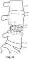
- FIGS. 3A-Billustrate a section of a vertebral column showing the bone fusion device inserted between two adjacent vertebrae in place of an intervertebral disc.
- FIGS. 4A-Billustrate a detailed view of the worm screw drive and the extendable tabs of some embodiments.
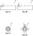
- FIGS. 5A-Billustrate the small form factor of some embodiments.
- FIGS. 6A-Billustrate a cross section view of the small form factor of some embodiments.
- FIGS. 7A-Bare perspective drawings illustrating the tabs and tab bays of some embodiments.
- FIG. 8illustrates a process flow in accordance with some embodiments of the invention.
- FIG. 9illustrates a top perspective view of the bone fusion device in some embodiments of the invention.
- FIG. 10illustrates a top/side perspective view of the bone fusion device in some embodiments of the invention.
- FIG. 11illustrates a top/side perspective view of the bone fusion device in some embodiments of the invention.
- FIG. 12illustrates a section of a vertebral column showing the bone fusion device inserted between two adjacent vertebrae in place of an intervertebral disc.
- FIG. 13illustrates a side perspective view of the bone fusion device in another embodiment of the present invention.
- FIG. 14Aillustrates a cross sectional view of the bone fusion device with the tabs compacted in another embodiment of the invention.
- FIG. 14Billustrates a cross sectional view of the bone fusion device with the tabs extended in another embodiment of the invention.
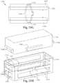
- FIG. 15illustrates a top perspective view of the bone fusion device in the preferred embodiment of the invention.
- FIG. 16illustrates a side perspective view of the bone fusion device in the preferred embodiment of the present invention.
- FIG. 17illustrates a cross-sectional view of components of the bone fusion device in the preferred embodiment of the present invention.
- FIG. 18Aillustrates a cross sectional view of the bone fusion device with the tabs compacted in the preferred embodiment of the invention.
- FIG. 18Billustrates a cross sectional view of the bone fusion device with the tabs extended in the preferred embodiment of the invention.
- FIG. 19illustrates a perspective view of a bone fusion device having one or more stops according to some embodiments.
- FIG. 20illustrates a frontal view of a tab having one or more stops according to some embodiments.
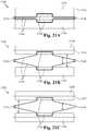
- FIG. 21Aillustrates a side cross-sectional view of a contracted bone fusion device having one or more retention springs according to some embodiments.
- FIG. 21Billustrates a side cross-sectional view of an extended bone fusion device having one or more retention springs according to some embodiments.
- FIG. 21Cillustrates a side cross-sectional view of an extended bone fusion device having one or more retention springs according to some embodiments.
- FIG. 21Dillustrates a front cross-sectional view of a tab of a bone fusion device having one or more retention springs according to some embodiments.
- FIG. 21Eillustrates a side cross-sectional view of an extended bone fusion device having one or more retention springs according to some embodiments.
- FIG. 21Fillustrates a side cross-sectional view of an extended bone fusion device having one or more retention springs according to some embodiments.
- FIG. 21Gillustrates a side cross-sectional view of an extended bone fusion device having one or more retention springs according to some embodiments.
- FIG. 21Hillustrates a perspective view of a bone fusion device having one or more retention springs according to some embodiments.
- FIG. 21Iillustrates a cross-sectional view of a retracted bone fusion device having one or more retention springs according to some embodiments.
- FIG. 21Jillustrates a cross-sectional view of an extended bone fusion device having one or more retention springs according to some embodiments.
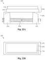
- FIG. 22Aillustrates a side cross-sectional view of a bone fusion device having one or more tabs with telescoping levels according to some embodiments.
- FIG. 22Billustrates a top view of a bone fusion device having one or more tabs with telescoping levels according to some embodiments.
- FIG. 22Cillustrates an exploded side cross-sectional view of a bone fusion device having one or more tabs with telescoping levels according to some embodiments.
- FIG. 22Dillustrates a bottom cross-sectional view of a bone fusion device having one or more tabs with telescoping levels according to some embodiments.
- FIG. 22Eillustrates a side cross-sectional view of a bone fusion device having one or more tabs with telescoping levels with tongues according to some embodiments.
- FIG. 22Fillustrates a top view of a bone fusion device having one or more tabs with telescoping levels with tongues according to some embodiments.
- FIG. 22Gillustrates a perspective view of a extending block of a bone fusion device having one or more tabs with telescoping levels according to some embodiments.
- FIG. 23illustrates a flow chart of a method of implanting a telescoping bone fusion device between bones according to some embodiments.
- FIG. 24illustrates a perspective view of a distraction instrument for measuring the space to be filled by a bone fusion device according to some embodiments.
- FIG. 25illustrates a top cross sectional view of the distraction body according to some embodiments.
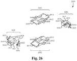
- FIG. 26illustrates a perspective view of the components of the retraction head of the retraction instrument according to some embodiments.
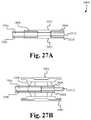
- FIG. 27Aillustrates cross sectional view of the head of the retraction instrument with the plates fully retracted according to some embodiments.
- FIG. 27Billustrates cross sectional view of the head of the retraction instrument with the plates fully extended according to some embodiments.
- FIG. 28illustrates a flow chart of a method of operating the retraction instrument according to some embodiments.
- FIG. 1illustrates a bone fusion device 100 in accordance with some embodiments of the invention.
- the bone fusion device 100has a round cylindrical shape and has two end faces, including the end face 140 .
- the bone fusion device 100is constructed from a high strength biocompatible material, such as titanium, which has the strength to withstand compressive and shear forces in the spine that are generated by a patient's body weight and daily movements.
- the base biocompatible materialis often textured or coated with a porous material conducive to the growth of new bone cells on the bone fusion device 100 .
- the end face 140has an opening 145 which allows the insertion of bone graft material into the bone fusion device 100 .
- the bone graft materialincludes bone chips from the same patient (autograft), bone chips from a donor (allograft or xenograft), and/or a synthetic bone matrix.
- the bone graft materialtypically promotes bone growth during a recovery period after the patient receives bone fusion surgery.
- the bone fusion device 100has several conduits or holes 150 , which permit the bone graft material to contact the vertebral bone after the device 100 has been inserted between the vertebrae of the patient.
- the bone graft material and the surface texturing of the device 100encourage the growth and fusion of bone from the neighboring vertebrae.
- the fusion and healing processwill result in the bone fusion device 100 becoming embedded within the two adjacent vertebrae of the spine which eventually fuse together during the healing period.
- tabs 131 , 132 , 133 , 134 , 135 , and 136are distributed along the round cylindrical body of the bone fusion device 100 .
- These tabs 131 - 136are each attached to the bone fusion device 100 by a respective rotating means 111 , 112 , 113 , 114 , 115 , and 116 .
- the rotating means 111 - 116is typically a turn screw type assembly.
- the unextended tabs 121 - 126 of the bone fusion device 100provide a compact assembly that is suitable for insertion into the patient's body through an arthroscopic surgical procedure.
- An arthroscopic procedureis considered minimally invasive and has certain advantages over more invasive conventional surgical procedures.
- a smaller surgical incisionis employed as compared to the size of the incision required for conventional invasive surgery.
- arthroscopic proceduresminimize or eliminate the need for excessive retraction of a patient's tissues such as muscles and nerves, thereby minimizing trauma and injury to the muscles and nerves and further reducing the patient's recovery time.
- each tab's 131 - 136 positionis individually adjustable so as to optimally brace the device 100 between the vertebrae. Due to the compressive forces commonly associated with spinal column vertebrae, some embodiments include a range of motion for each tab that is slightly greater than 90 degrees.
- the tabs of these embodimentsare rotated to an angle that is slightly more than about 90 degrees with respect to the surface of the bone fusion device.
- the tabs extended in this configurationwere found to be capable of withstanding the greatest amount of compressive force.
- the tabs 131 - 136when extended, abut tightly against the surfaces of the vertebrae that are immediately adjacent to the bone fusion device 100 .
- the tabs 131 - 136have sharp protrusions along the length of the tab for engaging the adjacent vertebrae, while the tabs 131 - 136 of some embodiments have screw-type threads for screwing into and engaging the vertebrae.
- the tabs of some embodimentshave surface texturing to encourage and enhance the growth of new bone on the tabs 131 - 136 . This surface texturing is often similar to the surface texturing used on the main body of the device 100 .
- the tabs 131 - 136advantageously wedge the bone fusion device 100 in a fixed position between the vertebrae and provide a larger surface area with which the adjacent vertebrae fuses during the healing period.
- bone growth materialsuch as protein, is typically applied to the tabs 131 - 136 to stimulate the regeneration of bone cells needed for bone fusion. The application of bone growth material is described further in relation to FIG. 4 .
- the tabs of the device 100have sharp ridges or threads which bite into the adjacent vertebrae, further helping to brace the device between the vertebrae.
- the body and the tabs 131 - 136 of the bone fusion device 100employs different numbers and/or configurations of tabs in different embodiments.
- the tabs 131 - 136 depicted in FIG. 1are merely exemplary.
- the tabs 131 - 136are located anywhere over the exterior surface of the bone fusion device 100 , in a variety of orientations.
- the tabs 131 - 136are arranged such that when they are extended, the tabs 131 - 136 act to stabilize the bone fusion device 100 against the vertebrae from several points and directions. Typically, the tighter the bone fusion device 100 is wedged between the adjacent vertebrae by the tabs 131 - 136 , the more stability the device 100 provides to the vertebrae and the spine of the patient.
- the tabs 131 - 136 of the embodiments described aboveare critical to insure that the device 100 is not dislodged, since movement of the device 100 could cause serious injury to the patient, and especially because the inserted device is situated near the patient's spinal cord.
- FIG. 2shows an alternative embodiment of the bone fusion device 200 .
- the bone fusion device 200 of some embodimentshas a rectangular shape. Similar to the round cylindrical shaped bone fusion device 100 shown in FIG. 1 , the rectangular bone fusion device 200 has two end faces, including the end face 245 visible in FIG. 2 , and multiple tabs 211 , 212 , 213 , 214 , 215 , 216 , 217 , and 218 that are attached by rotating means to the exterior surface.
- the rotating meansare screw type assemblies in some embodiments.
- the tabs 211 - 218are also selectively extended after insertion of the bone fusion device 200 between the vertebrae.
- the insertion of the bone fusion device 200 and the extension of the selected tabs 211 - 218are typically performed by a surgeon during an arthroscopic surgical procedure.
- the procedure of some embodimentsis further described in relation to FIG. 8 .
- the rotation of a respective rotating means associated with each tab 211 - 218individually adjusts the position of the associated tab 211 - 218 such that the device 200 is firmly braced between the two adjacent vertebrae.
- the tabs 211 - 218are distributed over the exterior surfaces of the bone fusion device 200 in a variety of configurations, which include the ends and the surfaces of the device 200 that are not readily visible in FIG. 2 .
- different numbers of tabs 211 - 218are distributed over each surface of the bone fusion device 200 of different embodiments.
- the surfaces of the bone fusion device 200 and/or the tabs 211 - 218are coated with a porous surface texturing which promotes bone growth.
- the end face 245has an opening 240 , which provides access to a cavity within the interior of the bone fusion device 200 .
- bone graft materialssuch as the bone chips and/or the synthetic bone matrix that were mentioned above, are pre-loaded into the cavity within the bone fusion device 200 through the opening 240 .
- Several conduits or holes 250 in the bone fusion device 200permit the bone graft material to flow from the interior cavity to the exterior surfaces of the device 200 that are in contact with the vertebral bone.
- the bone graft materialis relocated from the interior cavity to the exterior of the bone fusion device 200 , after the device 200 has been positioned between the vertebrae.
- the bone graft materialis delivered to the site of the bone fusion device 200 by arthroscopic means that originate external to the device 200 . Regardless of the delivery means, the bone graft material and the surface texturing of the bone fusion device 200 encourage bone growth and fusion with the adjacent vertebrae that are in contact with the device 200 . As bone fusion and healing progresses, the bone fusion device 200 becomes embedded within the two fused vertebrae of the spine.
- FIG. 3Aillustrates a section of a vertebral column that has a bone fusion device 300 positioned between two vertebrae 330 and 335 .
- the bone fusion device 300is positioned in a location where an intervertebral disc would normally reside.
- a flexible discis typically sandwiched between the two vertebrae of a normal healthy spinal column.
- the normal, healthy disc 340is sandwiched between the vertebrae 337 and 330 .
- the intervertebral disc that normally resides between the vertebrae 330 and 335has been excised and surgical insertion of the bone fusion device 300 has replaced the disc as the supporting structure between the vertebrae 330 and 335 .
- FIG. 3Afurther illustrates that the damaged disc that is normally sandwiched between vertebrae 330 and 335 has been totally removed.
- complete removal of the discis not necessary in order to use the bone fusion device 300 of some embodiments.
- a sufficient amount of the discis typically removed that allows access to the rotating means 311 , 312 , 313 , and 314 , which control the extension of the tabs 321 , 322 , 323 , and 324 , of the bone fusion device 300 .
- additional numbers and configurations of the tabsare distributed over the exterior surfaces of the bone fusion device 300 , including the surfaces that are not visible in FIG. 3A .
- the tabs 321 - 324are deposed in a position aligned along the body of the bone fusion device 300 , such that the tabs 321 - 324 lie substantially within the exterior surfaces of the device 300 .
- the tabs 321 - 324are flush with the exterior surface.
- the form factor of the bone fusion device 300is configured to be as compact as possible.
- the form factor of some embodimentshas a diameter of approximately 0.28 inches and a length of approximately 1.0 inch.
- the form factor of these same embodimentshas a diameter of approximately 0.48 inches when the tabs 321 - 324 are fully extended.
- the bone fusion device 300is advantageously inserted arthroscopically into the patient's body. If instead, the device 300 were inserted in its fully extended form, a larger surgical incision would be required, and a greater displacement of the muscles and nerves would be needed. However, its compact form factor allows the bone fusion device 300 to be inserted by advantageously utilizing minimally invasive arthroscopic techniques. Then, the tabs 321 - 324 of the bone fusion device 300 are extended after arthroscopic insertion to optimally increase the form factor and brace the device 300 between the vertebrae 330 and 335 . In some embodiments, selected tabs 321 - 324 are extended.
- the cross-section of the bone fusion device 300has different shapes in various embodiments.
- a more circular bone fusion devicesuch as the device 100 illustrated in FIG. 1 , or a device having another shape is employed in conjunction with a set of extendable tabs that are located in various configurations in additional embodiments of the invention.
- some embodimentshave four rows of tabs, where each row is positioned on a side of the bone fusion device. In some of these embodiments, each row has four tabs.
- FIG. 7Such an embodiment is further described in relation to FIG. 7 and is illustrated in its inserted form in FIG. 3B .
- a first set of four tabs 311 - 314lock the bone fusion device 300 against the vertebra 330
- a second set of tabs 315 - 318lock the bone fusion device 300 against the vertebra 335 .
- FIG. 4Aillustrates the bone fusion device 400 of some embodiments in further detail.
- the bone fusion device 400includes an interior cavity 405 for the insertion of a lead screw 415 , and one or more tabs 431 each deposed in a tab bay 421 , 422 , 423 , 424 .
- the tab bays 421 - 424allow the tabs 431 to lie flush and/or within the exterior surface 420 of the bone fusion device 400 when not extended. Also when not extended, the tab 431 and tab bay 421 provides a conduit 450 from the interior cavity 405 to the exterior surface 420 of the bone fusion device 400 , such that the bone graft and/or growth material within the interior cavity 405 has a directed path to the exterior surface 420 . Typically, the insertion of the lead screw 415 forces the material within the interior cavity 405 to relocate to the exterior surface 420 .
- the tab 431includes a rotating means 411 and gear teeth 455 .
- the gear teeth 455provide a series of passive grooves by which the lead screw 415 traverses the interior cavity 405 .
- the tab 431remains fixed as the lead screw 415 is screwed into the interior cavity 405 .
- the threading of the lead screw 415does not address or affect the gear teeth 455 during the insertion of the lead screw 415 .
- the gear teeth 455do employ the threading of the lead screw 415 when the lead screw 415 has been fully inserted into the cavity 405 , in some embodiments.
- the lead screw 415is driven into the cavity 405 , until it reaches an endcap 406 .
- the endcap 406allows the lead screw 415 to continue rotating in place, but does not allow the lead screw 415 to continue its forward progress through the cavity 405 .
- the rotating lead screw's threadingcontacts and engages the gear teeth 455 of each tab 431 . Accordingly, the motion and angle of the spiraling threads, when applied against the gear teeth 455 , causes the tabs 431 to elevate and extend.
- the combination of the gear teeth 455 on the tabs 431 and the inserted lead screw 415is referred to, in some embodiments, as a worm screw drive mechanism.
- the rotating means 411is turned to raise the tab 431 .
- the rotating means 411 for the tab 431typically comprises a turn screw type mechanism such that when the rotating means 411 is turned, the gear teeth 455 drive or rotate against the stationary threads of the inserted lead screw 415 . Similarly, due to the angle of the stationary lead screw's spiral threads, the gear teeth 455 cause the tab 431 to elevate and extend above the exterior surface 420 of the bone fusion device 400 .
- the tabs 431 of some embodimentshave a range of motion that exceeds 90 degrees with respect to the exterior surface 420 of the bone fusion device 400 . Accordingly, FIG. 4B illustrates the tab 431 extended slightly past 90 degrees, which is the optimum position to withstand the compressive force exerted on the vertebrae of some embodiments.
- FIG. 5Aillustrates a closed view of the small form factor for a bone fusion device 500 in accordance with some embodiments.
- the bone fusion device 500has a tab 531 that is not extended and lies within the exterior surface of the device 500 .
- FIG. 5Billustrates the form factor for the bone fusion device 500 with the tab 531 extended, as described above.
- FIG. 6Aillustrates a cross section view of the bone fusion device 600 having a small form factor, while FIG. 6B illustrates the cross section view with the tab 631 extended.
- FIG. 7Ais a perspective drawing illustrating the bone fusion device 700 with four tab bays on four opposite sides of the device 700 , according to some embodiments of the invention.
- a tabis deposed in each tab bay and secured by a rotating means.
- the tab 731is deposed in the tab bay 721 and secured by the rotating means 711 .
- a lead screw 715is driven into the cavity.
- the lead screw 715provides the thread by which the gear teeth 755 elevate the tabs 731 - 733 .
- FIG. 7Billustrates the bone fusion device 700 with the tabs 731 - 733 elevated.
- FIG. 8is a process flow diagram that summarizes the insertion and use of the bone fusion device according to some embodiments.
- the process 800begins at the step 805 where a small, minimally invasive surgical incision is performed.
- the small incisionis typically only large enough to permit entry of an arthroscopic surgical tool.
- the process 800transitions to the step 810 , where the bone fusion device is inserted through the small incision and delivered to a region between two vertebrae that are to be fused together. Insertion and delivery of the bone fusion device are performed by using arthroscopic tool(s).
- the bone fusion deviceis positioned in the region where bone fusion is to occur, also typically by using one or more arthroscopic tool(s).
- the process 800transitions to the step 820 , where the lead screw is inserted and driven into the bone fusion device.
- the lead screwis typically driven into a cavity in the center of the bone fusion device.
- the cavitycontains a bone growth material comprising collagen and/or a matrix for the promotion of bone growth. Accordingly, insertion of the lead screw into the cavity causes the bone growth material to be relocated from the interior cavity to the exterior surface of the bone growth device.
- the bone fusion device of some embodimentshas a particular pattern of conduits or pores that extend from the interior cavity to the exterior surface for facilitating the relocation of bone growth material to particular locations at the exterior of the device. For instance, some embodiments have pores that facilitate the relocation of bone growth material to particular tabs.
- the tabsare selectively extended to lock the bone fusion device in place in the region between the two vertebrae.
- the tabs of some embodimentsare extended by using the worm screw drive mechanism described above in relation to FIG. 4 .
- FIG. 9illustrates a top perspective view of the bone fusion device in some embodiments.
- the bone fusion device 1000has a substantially rectangular shape and has two end faces.
- the bone fusion device 1000is constructed from a high strength biocompatible material, such as titanium, which has the strength to withstand compressive and shear forces in the spine that are generated by a patient's body weight and daily movements.
- the base biocompatible materialis often textured or coated with a porous material conducive to the growth of new bone cells on the bone fusion device 1000 .
- the bone fusion device 1000has several conduits or holes 1014 which permit the bone graft material to contact the vertebral bone after the device 1000 has been inserted between the vertebrae of the patient.
- the bone graft material and the surface texturing of the device 1000encourage the growth and fusion of bone from the neighboring vertebrae.
- the fusion and healing processwill result in the bone fusion device 1000 becoming embedded within the two adjacent vertebrae of the spine which eventually fuse together during the healing period.
- a first tab 1006is located on a first side and a second tab 1006 ( FIG. 14A ) is located on an opposing second side.
- These tabs 1006are shaped so that their outer surface is substantially flush with the frame 1004 of the bone fusion device 1000 in an unextended position. Internally, the tabs 1006 have an angled inner surface. Each tab 1006 is shaped such that one end is substantially larger than the opposing smaller end, and the size of the tab in between gradually decreases while going from the larger end to the opposing smaller end.
- a positioning means 1002is coupled to an extending block or nut 1010 which travels up or down the positioning means 1002 depending on which way the positioning means 1002 is turned.
- the positioning means 1002is typically a screw type assembly. Turning the positioning means 1002 clockwise causes the extending block 1010 to move up the positioning means 1002 towards the head of the positioning means 1002 , whereas turning the positioning means 1002 counterclockwise moves the extending block 1010 away from the head of the positioning means 1002 .
- the angled tabs 1006are compact and are within the frame 1004 of the bone fusion device 1000 .
- the unextended tabs 1006 of the bone fusion device 1000provide a compact assembly that is suitable for insertion into the patient's body through an arthroscopic surgical procedure.
- An arthroscopic procedureis considered minimally invasive and has certain advantages over more invasive conventional surgical procedures.
- a smaller surgical incisionis employed as compared to the size of the incision required for conventional invasive surgery.
- arthroscopic proceduresminimize or eliminate the need for excessive retraction of a patient's tissues such as muscles and nerves, thereby minimizing trauma and injury to the muscles and nerves and further reducing the patient's recovery time.
- the tabs 1006are fully extended. Furthermore, since the extending block 1010 travels along the positioning means 1002 , such as along the threads of a screw, very precise positions of the tabs 1006 are able to be achieved.
- FIG. 10illustrates a top/side perspective view of the bone fusion device 1000 in some embodiments.
- the bone fusion device 1000has tabs 1006 initially positioned so that they fit within the frame 1004 of the bone fusion device 1000 .
- the positioning means 1002is positioned through the first end face 1018 so that the extending block 1010 is able to travel along the positioning means 1002 causing the tabs 1006 to extend outwardly beyond the frame 1004 of the bone fusion device 1000 .
- the positioning means 1002is able to be any device that allows such functionality.
- any type of screw headis acceptable even though the exemplary screw slot shown in FIG. 10 requires the use of an allen wrench.
- first end face 1018Also located within the first end face 1018 are one or more apertures 1016 to allow bone graft material to contact the vertebral bone after the device 1000 has been inserted between the vertebrae of the patient.
- the holes 1014 within the tabs 1006also permit the insertion of bone graft material.
- FIG. 11illustrates a top/side perspective view of the bone fusion device 1000 in some embodiments.
- the bone fusion device 1000utilizes the positioning means 1002 to move the extending block 1010 up and down the body of the positioning means 1002 which forces the tabs 1006 to either extend or retract depending on the position of the extending block 1010 .
- the extending block 1010forces the tabs 1006 outward so that the tabs 1006 are extended beyond the frame 1000 to secure the bone fusion device 1000 in place.
- the tabs 1006are situated within the frame 1004 , making the bone fusion device 1000 very compact.
- the second end face 1020Opposing the end of the head of the positioning means is the second end face 1020 which contains an opening 1012 for providing access to a cavity within the interior of the bone fusion device 1000 .
- bone graft materialssuch as the bone chips and/or the synthetic bone matrix that were mentioned above, are pre-loaded into the cavity within the bone fusion device 1000 through the opening 1012 .
- the other holes 1014 within the tabsallow the bone graft material to contact the vertebral bone after the device 1000 has been inserted between the vertebrae of the patient.
- FIG. 12illustrates a section of a vertebral column showing the bone fusion device 1000 inserted between two adjacent vertebrae 330 and 335 in place of an intervertebral disc.
- the bone fusion device 1000is positioned in a location where an intervertebral disc would normally reside.
- a flexible discis typically sandwiched between the two vertebrae of a normal healthy spinal column.
- the normal, healthy disc 340is sandwiched between the vertebrae 337 and 330 .
- the intervertebral disc that normally resides between the vertebrae 330 and 335has been excised and surgical insertion of the bone fusion device 1000 has replaced the disc as the supporting structure between the vertebrae 330 and 335 .
- the tabs 1006are deposed in a position aligned along the body of the bone fusion device 1000 , such that the tabs lie substantially within the exterior surfaces of the device. In some embodiments, the tabs 1006 are flush with the exterior surface.
- the form factor of the bone fusion device 1000is configured to be as compact as possible. For example, the form factor of some embodiments has a diameter of approximately 0.28 inches and a length of approximately 1.0 inch. In contrast, the form factor of these same embodiments has a diameter of approximately 0.48 inches when the tabs 1006 are fully extended. In other embodiments the size could be larger or smaller as needed.
- the bone fusion device 1000is advantageously inserted arthroscopically into the patient's body. If instead, the device 1000 were inserted in its fully extended form, a larger surgical incision would be required, and a greater displacement of the muscles and nerves would be needed. However, its compact form factor allows the bone fusion device 1000 to be inserted by advantageously utilizing minimally invasive arthroscopic techniques. Then, the tabs 1006 of the bone fusion device 1000 are extended after arthroscopic insertion to optimally increase the form factor and brace the device 1000 between the vertebrae 330 and 335 .
- FIG. 13illustrates a side view of another embodiment of the bone fusion device 1000 ′.
- the bone fusion device 1000 ′utilizes the positioning means 1002 to move the extending block 1010 ( FIG. 9 ) up and down the body of the positioning means 1002 which forces the tabs 1006 ′ to either extend or retract depending on the position of the extending block 1010 ( FIG. 9 ).
- the tabs 1006 ′have serrated edges 1026 to further increase the bone fusion device's gripping ability to secure it in place between the bones.
- the tabs 1006 ′are each coupled to the frame 1004 of the bone fusion device 1000 ′ by one or more slots 1028 and one or more pins 1024 wherein the one or more pins 1024 fit within the one or more slots 1028 and are able to travel along the interior of the one or more slots 1028 .
- the extending block 1010FIG. 9
- the tabs 1006 ′are situated within the frame 1004 , making the bone fusion device 1000 ′ very compact.
- the holes 1014 within the tabsallow the bone graft material to contact the vertebral bone after the device 1000 ′ has been inserted between the vertebrae of the patient.
- FIG. 14Aillustrates a cross sectional view of the bone fusion device 1000 ′ with the tabs 1006 ′ with serrated edges 1026 compacted in another embodiment.
- the tabs 1006 ′are positioned within the frame 1004 of the bone fusion device 1000 ′.
- the tabs 1006 ′are coupled to the frame 1004 of the bone fusion device by the one or more slots 1028 and the one or more pins 1024 wherein the one or more pins 1024 fit within the one or more slots 1028 and are able to travel along the interior of the one or more slots 1028 .
- FIG. 14Billustrates a cross sectional view of the bone fusion device 1000 ′ with the tabs 1006 ′ with serrated edges 1026 extended in another embodiment.
- the tabs 1006 ′extend beyond the frame 1004 of the bone fusion device 1000 ′ and ultimately secure the bone fusion device 1000 ′ between two bones.
- the tabs 1006 ′extend because the extending block 1010 pushes the angled tabs 1006 outwardly as shown by the arrows 1022 .
- the position of the extending block 1010is changed by rotating the positioning means 1002 either clockwise or counterclockwise.
- the tabs 1006 ′are extended outward due to the force of the extending block 1010 . With the tabs 1006 ′ coupled to the frame 1004 of the bone fusion device by the one or more slots 1028 and the one or more pins 1024 , the tabs 1006 ′ are able to extend beyond the frame of the bone fusion device 1000 ′ as the one or more pins 1024 travel within the interior of the one or more slots 1028 .
- the bone fusion deviceincludes one or more pivots or any other rotating means that allows movement of the tabs wherein the one or more pivots are located at either end of the tabs.
- the bone fusion deviceTo utilize the bone fusion device is some embodiments, it is initially configured in a compact position such that the extending block is located away from the head of the positioning means and towards the second end face thereby allowing the tabs to rest within the frame of the bone fusion device.
- the compact bone fusion deviceis then inserted into position within the patient.
- the surgeonis able to then the expand the bone fusion device by rotating the positioning means which moves the extending block towards the head of the positioning means and the first end face.
- the tabsare pushed outwardly from the pressure of the extending block against the angled tabs.
- the extending blockmoves close enough to the first end face causing enough pressure between the extended tabs and the bones to be fused.
- the bone fusion deviceis able to remain in place.
- material for fusing the bones togetheris inserted through the holes and openings within the bone fusion device.
- FIG. 15illustrates a top perspective view of the bone fusion device in the preferred embodiment of the invention.
- the bone fusion device 1500has a substantially rectangular shape and has two end faces.
- the bone fusion device 1500is preferably constructed from a high strength biocompatible material, such as titanium, which has the strength to withstand compressive and shear forces in the spine that are generated by a patient's body weight and daily movements.
- the base biocompatible materialis often textured or coated with a porous material conducive to the growth of new bone cells on the bone fusion device 1500 .
- the bone fusion device 1500has several conduits or holes 1520 ( FIG. 16 ) and 1534 which permit the bone graft material to contact the vertebral bone after the device 1500 has been inserted between the vertebrae of the patient.
- the bone fusion device 1500comprises a radio frequency identification (RFID) chip 1501 that uniquely identifies the bone fusion device 1500 , provides information about the characteristics of the bone fusion device 1500 , provides information about the patient in which the bone fusion device 1500 is implanted, provides information about the procedure used to implant the bone fusion device 1500 and/or other types of information.
- RFID chip 1501is passive. Alternatively, the RFID chip 1501 is active. As a result, the bone fusion device 1500 is able to provide the benefit of enable the RFID chip 1501 to be scanned and the information contained on the chip 1501 to be accessed for beneficial use.
- tabs 1530are located on opposing sides of the bone fusion device 1500 .
- the tabs 1530are shaped so that their outer surface is substantially flush with the frame 1514 of the bone fusion device 1500 in a nonextended position. Internally, the tabs 1530 have an angled inner surface.
- Each tab 1530is shaped such that the ends are larger than the middle, and the size of the tab 1530 gradually increases while going from the middle to the ends.
- a positioning means 1508 within the frame 1514 of the bone fusion device 1500comprises a first screw 1502 and a second screw 1504 coupled together. The first screw 1502 is threaded opposite of the second screw 1504 .
- the positioning means 1508is coupled to a first extending block 1510 and a second extending block 1512 .
- the first extending block 1510is coupled to the first screw 1502 and the second extending block 1512 is coupled to the second screw 1504 .
- the first extending block 1510 and the second extending block 1512are positioned in the middle of the bone fusion device 1500 in the compact position.
- the positioning means 1508is turned appropriately, the extending blocks 1510 and 1512 each travel outwardly on their respective screws 1502 and 1504 .
- the positioning device 1508is turned in the opposite direction and the extending blocks 1510 and 1512 will each travel back to the middle on their respective screws 1502 and 1504 .
- the tabs 1530are compact and are within the frame 1514 of the bone fusion device 1500 .
- the nonextended tabs 1530 of the bone fusion device 1500provide a compact assembly that is suitable for insertion into the patient's body through an arthroscopic surgical procedure.
- An arthroscopic procedureis considered minimally invasive and has certain advantages over more invasive conventional surgical procedures.
- arthroscopic proceduresIn an arthroscopic procedure, a smaller surgical incision is employed as compared to the size of the incision required for conventional invasive surgery. Moreover, arthroscopic procedures minimize or eliminate the need for excessive retraction of a patient's tissues such as muscles and nerves, thereby minimizing trauma and injury to the muscles and nerves and further reducing the patient's recovery time.
- the positioning means 1508As the positioning means 1508 is rotated causing the extending blocks 1510 and 1512 to move closer to the ends of the respective screws 1502 and 1504 , the extending blocks 1510 and 1512 push the tabs 1530 outward causing the tabs 1530 to assert pressure against surrounding bones and securing the bone fusion device 1500 in place.
- the tabs 1530When the extending blocks 1510 and 1512 reach as close to the head of the positioning means 1508 as allowed, the tabs 1530 are fully extended. Furthermore, since the extending blocks 1510 and 1512 travel along the positioning means 1508 , along the threads of the screws 1502 and 1504 , very precise positions of the tabs 1530 are able to be achieved.
- the tabs 1530have serrated edges 1536 to further increase the bone fusion device's gripping ability to secure it in place between the bones.
- a userTo secure the bone fusion device 1500 in place, a user generally utilizes an implement such as a screw driver to turn the positioning means 1508 . Screw drivers unfortunately have the ability to slip out of place. When performing surgery near someone's spine, it is preferable to prevent or at least minimize the slipping ability. To do so, channels 1522 are implemented to receive a tool (not shown). The tool (not shown) has attachments that fit within the channels 1522 to secure the tool (not shown) in place.
- FIG. 16illustrates a side perspective view of the bone fusion device in the preferred embodiment of the present invention.
- the bone fusion device 1500utilizes the positioning means 1508 comprising the first screw 1502 and the second screw 1504 to move the first extending block 1510 and the second extending block 1512 outwardly from the middle of the bone fusion device 1500 towards its ends.
- the positioning means 1508is held in place but permitted to turn utilizing one or more first pins 1516 .
- the one or more first pins 1516are secured within a retaining groove 1506 ( FIG. 17 ) of the positioning means 1508 .
- the extending blocks 1510 and 1512force the tabs 1530 to either extend or retract depending on where the extending blocks 1510 and 1512 are positioned.
- the tabs 1530have serrated edges 1536 to further increase gripping ability.
- the tabs 1530are each coupled to the frame 1514 of the bone fusion device 1500 by one or more slots 1532 ( FIG. 18A ) and one or more second pins 1518 wherein the one or more second pins 1518 fit within the one or more slots 1532 and are able to travel along the interior of the one or more slots 1532 .
- the holes 1534 within the tabs 1530allow the bone graft material to contact the vertebral bone after the device 1500 has been inserted between the vertebrae of the patient.
- a set of holes 1520 within the frame 1514also allow bone graft material to be inserted within the bone fusion device 1500 after the bone fusion device 1500 has been placed.
- the channels 1522 implemented to receive a toolare shown as well.
- FIG. 17illustrates a cross-sectional view of components of the bone fusion device in the preferred embodiment of the present invention.
- the positioning means 1508comprises a first screw 1502 and a second screw 1504 wherein the first screw 1502 is threaded differently than that of the second screw 1504 .
- the first screw 1502is of a slightly different size than the second screw 1504 .
- the first screw 1502is an 8-32 screw and the second screw is a 6-32 screw.
- a retaining groove 1506is utilized to secure the positioning means 1508 in place.
- channels 1522are utilized to secure the device.
- a first extending block 1510 and a second extending block 1512are utilized with the positioning means 1508 to extend and compact a plurality of tabs 1530 .
- the first extending block 1510has an internal opening to fit around the first screw 1502 .
- the second extending block 1512has an internal opening to fit around the second screw 1504 .
- the frame 1514 of the bone fusion device 1500contains a set of holes 1520 within the frame 1514 for allowing bone graft material to be inserted.
- one or more first pins 1516secure the positioning means within the frame 1514 .
- One or more second pins 1516 in conjunction with one or more slots 1532secure the tabs 1530 to the frame 1514 .
- FIG. 18Aillustrates a cross sectional view of the bone fusion device with the tabs compacted in the preferred embodiment of the invention.
- the extending blocks 1510 and 1512are positioned in the middle of the positioning means 1508 with the first screw 1502 and the second screw 1504 , the tabs 1530 are positioned within the frame 1514 of the bone fusion device 1500 .
- the positioning means 1508contains a retaining groove 1506 for holding the positioning means 1508 in place with one or more first pins 1516 .
- the tabs 1530are coupled to the frame 1514 of the bone fusion device 1500 using the one or more slots 1532 and the one or more second pins 1518 wherein the one or more second pins 1518 fit within the one or more slots 1532 and are able to travel along the interior of the one or more slots 1532 .
- FIG. 18Billustrates a cross sectional view of the bone fusion device with the tabs extended in the preferred embodiment of the invention.
- the bone fusion device 1500is compressed when the extending blocks 1510 and 1512 are in the middle of the bone fusion device 1500 .
- the positioning means 1508As a user turns the positioning means 1508 , the extending blocks 1510 and 1512 gradually move outward from the middle. If the user turns the positioning means 1508 in the opposite direction, the extending blocks move back towards the middle. As the extending blocks 1510 and 1512 are moving outward, they push on the tabs 1530 .
- the tabs 1530extend because the extending blocks 1510 and 1512 exert force the angled tabs 1530 outwardly as shown by the arrows 1540 .
- the tabs 1530extend beyond the frame 1514 of the bone fusion device 1500 and ultimately secure the bone fusion device 1500 between two bones.
- the tabs 1530coupled to the frame 1514 of the bone fusion device 1500 by the one or more slots 1532 and the one or more second pins 1518 , the tabs 1530 are able to extend beyond the frame 1514 of the bone fusion device 1500 as the one or more second pins 1518 travel within the interior of the one or more slots 1532 .
- the bone fusion deviceTo utilize the bone fusion device in the preferred embodiment, it is initially configured in a compact position such that the extending blocks are located in the middle of the bone fusion device thereby allowing the tabs to rest within the frame of the bone fusion device.
- the compact bone fusion deviceis then inserted into position within the patient.
- the surgeonis able to then the expand the bone fusion device by rotating the positioning means which moves the extending blocks towards the opposing ends of the bone fusion device—one near the head of the positioning means and the other towards the tail of the positioning means.
- the extending blocksmove away from the middle, the tabs are pushed outwardly from the pressure of the extending block against the angled tabs.
- the extending blocksexert a satisfactory force between the extended tabs and the bones to be fused.
- the bone fusion deviceis able to remain in place.
- material for fusing the bones togetheris inserted through the holes and openings within the bone fusion device.
- FIG. 19illustrates a perspective view of a bone fusion device 1900 having one or more stops according to some embodiments.
- the bone fusion device 1900 shown in FIG. 19is substantially similar to the bone fusion device 1500 except for the differences described herein. Specifically, instead of the pin and slot system of the bone fusion device 1500 , the bone fusion device 1900 comprises a body 1902 having one or more recesses 1908 and one or more tabs 1904 having one or more stops 1906 .
- the tabs 1904each comprise five stops 1906 positioned along the bottom perimeter of the tabs 1904 . However, it is understood that the tabs 1904 are each able to comprise any number of stops 1906 positioned anywhere along the perimeter of the tabs 1904 .
- the recesses 1908are sized and positioned within the body 1902 such that the recesses 1908 are each able to receive at least one of the stops 1906 when the tabs 1904 are inserted into the body 1902 .
- the stops 1906are able to slide up and down the recesses 1908 as the tabs 1904 are extended out and retracted within the body 1902 .
- the recesses 1908are able to be configured to block the outward/extension movement of the stops 1906 at a desired maximum extension point thereby preventing the tabs 1904 from extending beyond the maximum extension point and/or falling out of the body 1902 .
- each stop 1906has a separate associated recess 1908 such that there is one recess 1908 for each stop 1906 .
- one or more of the stops 1906are able to share a single recess 1908 ′.
- FIG. 20illustrates a frontal view of a tab 1904 having one or more stops 1906 according to some embodiments.
- the stops 1906comprise a stop outer surface 1912 that is angled with respect to the surface of the perimeter of the tab 1904 such that the lower portion of the stop 1906 is closer to the perimeter of the tab 1904 than the upper portion of the stop 1906 .
- the stop outer surface 1912is able to facilitate the insertion of the tabs 1904 into the body 1902 by causing the tab 1904 to compress when entering the opening of the body 1902 and then decompress as the stops 1906 slide into the recesses 1908 within the body 1902 .
- one or more of the stops 1906comprise a stop channel 1910 than enables the stops 1906 to flex inwardly when the tab 1904 is inserted into the body 1904 and spring back into place when the stops 1906 align with the recesses 1908 .
- the stop channel 1910is able to be sized to receive a retention spring 2106 (see FIG. 21 ) in order to facilitate the coupling of the tab 1904 with the retention spring 2106 .
- the stops 1906are able to replace or supplement the tab protrusions 2108 .
- the bone fusion device 1900provides the advantage of better securing the tabs 1904 within the body 1902 of the device 1900 . Also, it is understood that the differences to the bone fusion device 1900 described in FIGS. 19 and 20 are able to be incorporated with and/or replace components of each of the other bone fusion devices described herein.
- FIGS. 21A-21Jillustrate views of a bone fusion device 2100 having one or more retention springs according to some embodiments.
- the bone fusion device 2100 shown in FIGS. 21A-21Jis substantially similar to the bone fusion device 1500 except for the differences described herein. Further, it is understood that although FIGS. 21A-21J illustrate a number of tabs and retention springs, any number of tabs and retention springs are contemplated.
- FIGS. 21A and 21Billustrate side cross-sectional views of a bone fusion device 2100 having tabs in the contracted and extended positions, respectively. As shown in FIGS.
- the bone fusion device 2100comprises a body 2102 having one or more spring receptors 2110 , one or more tabs 2104 having tab protrusions 2108 and one or more retention springs 2106 .
- the retention springs 2106comprise a wire such as a nitinol wire.
- the retention springs 2106are able to comprises other dimensions and/or materials as are well known in the art.
- the device 2100comprises at least one retention spring 2106 for each tab 2104 .
- a single retention spring 2106is able to contact and/or be coupled to multiple tabs 2104 .
- the ends of the retention springs 2106are positioned and/or coupled within the spring receptors 2110 such that the ends of the retention springs 2106 do not move with respect to the body 2102 .
- the middle of the retention springs 2106is coupled to and/or positioned such that it blocks the outward movement of the tab protrusions 2108 of each of the tabs 2104 in order to resist the movement of the tabs 2104 into the extended position. As shown in FIG. 21B , when a user causes the tabs 2104 and their corresponding tab protrusions 2108 move/extend out of the body 2102 , the protrusions 2108 cause the retention springs 2106 to flex.
- the resistence to this flexure by the retention springs 2106biases the tabs 2104 toward the retracted position such that when the user retracts the tabs 2104 they do not get stuck in the extended position.
- the bone fusion device 2100provides the benefit of ensuring that the tabs 2104 retract properly when retracted from an extended position.
- the each retention spring 2106is coupled/associated with a single tab 2104 and/or tab protrusion 2108 .
- the bone fusion device 2100is able to comprise a single continuous retention spring 2106 that couples with multiple tabs 2104 and/or tab protrusions 2108 .
- the tab protrusions 2108each comprise a protrusion channel 2112 that is configured for receiving the retention springs 2106 .
- the channels 2112are able to ensure that the retention springs 2106 do not slip off of the protrusions 2108 during operation.
- the tab protrusions 2108comprise one or more protrusion apertures 2114 that are configured to receive the retention springs 2106 .
- the protrusion apertures 2114enable the retention springs 2106 to be secured to the tab protrusions 2108 .
- FIG. 21Fillustrates a side cross-sectional view of the bone fusion device 2100 having one or more retention springs according to some embodiments.
- the retention springs 2106 of FIG. 21Fare coupled between a tab protrusion 2108 of a first tab 2104 and the tab protrusion 2108 of a second tab 2104 .
- the resistance provided by the retention springs 2106 in order to bias the tabs 2104 into the retracted positionis able to be increased as the retention springs 2106 are flexed in both directions by the oppositely moving tabs 2104 .
- FIG. 21Gillustrates a side cross-sectional view of the bone fusion device 2100 having one or more retention springs according to some embodiments.
- the bone fusion device 2100instead of tab protrusions 2108 and/or spring receptors 2110 , the bone fusion device 2100 comprises tabs 2104 having tab channels 2116 and one or more ring or looped retention springs 2106 .
- the ring or looped retention springs 2106are able to be wrapped around the tabs 2104 one or more times in order to bias the tabs 2104 in the retracted position.
- the tab channels 2116are able to be configured to receive at least a portion of the ring or looped retention springs 2106 in order to prevent the springs 2106 from sliding off and/or moving with respect to the tab 2104 .
- a single ring or looped retention spring 2106 looped around the tabs 2104 onceis shown in FIG. 21G , any number of retention springs 2106 looped any number of times is contemplated.
- FIG. 21Hillustrates a perspective view
- FIGS. 21I and 21Jillustrate cross-sectional side views of the bone fusion device 2100 wherein the retention springs are incorporated into the body according to some embodiments.
- the body 2102comprises a plurality of wall cavities 2116 , 2116 ′ wherein the retention springs 2106 , 2106 ′ are coupled to the body 2102 and positioned within the wall cavities 2116 , 2116 ′.
- the tab protrusions 2108are configured to fit within the wall cavities 2116 , 2116 ′ below the retention springs 2106 , 2106 ′ such that, as shown in FIGS.
- the retention springs 2106 , 2106 ′are flexed within the wall cavities 2116 , 2116 ′ causing the springs 2106 , 2106 ′ to apply an opposite biasing force.
- This biasing forceensures that the tabs 2104 properly retract when a user manipulates the bone fusion device 2100 in order to retract the tabs 2104 .
- the retention springs 2106are continuous such that the retention spring 2106 continues from a connection to the body 2102 on one side of the cavity 2116 to a connection to the body 2102 on the opposite side of the cavity 2116 .
- one or more of the retention springs 2106 ′are able to be discontinuous such that two or more separate retention springs 2106 ′ couple to the opposite sides of the cavity 2116 ′ of the body 2102 and meet approximately in the middle of the cavity 2116 ′.
- the retention springs 2106 , 2106 ′are configured, positioned and coupled within the cavities 2116 , 2116 ′ such that they bias the tabs 2104 in the retracted position.
- the bone fusion device 2100 of FIGS. 21H-21Jprovides the advantage of ensuring the tabs 2104 are able to be properly retracted via biasing using retention springs.
- the retention springs 2106comprise PEEK or PEEKsil.
- the retention springs 2106are able to comprise other bio-compatible materials with springing properties as are well known in the art. It is understood that the differences to the bone fusion device 2100 described in FIGS. 21A-21J are able to be incorporated with and/or replace components of each of the other bone fusion devices described herein.
- FIGS. 22A-22Gillustrate views of a bone fusion device 2200 having one or more tabs with telescoping levels according to some embodiments.
- the bone fusion device 2200 shown in FIGS. 22A-22Gis substantially similar to the bone fusion device 1500 except for the differences described herein. Further, it is understood that although FIGS. 22A-22G illustrate a number of tabs with telescoping levels, any number of tabs with any number of telescoping levels is contemplated.
- FIGS. 22A-22Dillustrate side, top, exploded side and bottom cross-sectional views of a bone fusion device 2200 having one or more tabs with telescoping levels according to some embodiments. As shown in FIGS.
- the bone fusion device 2200comprises a body 2202 , one or more tabs 2204 each having a plurality of tab levels 2206 , 2206 ′, one or more positioning elements 2208 and one or more extending blocks 2210 .
- the levels 2206 , 2206 ′ of each tab 2204are nested such that an innermost level 2206 ′ is surrounding by one or more outer levels 2206 .
- the outer levels 2206 ′are able to be positioned adjacent to but not surrounding the relatively inner levels 2206 , 2206 ′.
- each of the levels 2206 , 2206 ′have an inner surface 2211 , 2211 ′ having an inner surface profile 2212 , 2212 ′ that is contoured in a manner that controls the extension and retraction of the associated level 2206 , 2206 ′ when pushed by the extending blocks 2210 .
- FIGS. 22C and 22Deach of the levels 2206 , 2206 ′ have an inner surface 2211 , 2211 ′ having an inner surface profile 2212 , 2212 ′ that is contoured in a manner that controls the extension and retraction of the associated level 2206 , 2206 ′ when pushed by the extending blocks 2210 .
- the inner surface profiles 2212 , 2212 ′ and/or the extending blocks 2210are able to be configured such that as the extending blocks 2210 separate both the innermost and outer level 2206 , 2206 ′ simultaneously extend to a first extended height beyond which the outer level 2206 stops and the innermost level 2206 ′ continues to extend to a second extended height. Conversely, when the extending blocks 2210 are moved closer together, the innermost level 2206 ′ retracts from the second extended height to the first extended height beyond which both the innermost and the outer levels 2206 , 2206 ′ simultaneously retract until in the retracted position.
- each level 2206 , 2206 ′is able to have a differently contoured inner surface 2211 , 2211 ′ having an inner surface profile 2212 , 2212 ′ that aligns with a differently angled and/or sized extending block surface such that the movement of each level 2206 , 2206 ′ is individually customizable.
- the bone fusion device 2200provides the benefit of enabling the tab levels to extend in a telescoping or other type of extending action to various heights and at various rates as desired. This is able to be used to achieve desired extension heights as well as to provide increased lateral support to the innermost level 2206 ′ when extended to the maximum extended position due to the support provided to the innermost level 2206 ′ by the outer levels 2206 positioned at less than maximum extended positions.
- FIGS. 22E and 22Fillustrate an exploded side and a top view of the bone fusion device 2200 having nested tab levels with tongues according to some embodiments.
- the extending blocks 2210comprise a plurality of upper surfaces 2218 , 2220 at different heights and/or angles.
- FIG. 22Eillustrates an exploded side and a top view of the bone fusion device 2200 having nested tab levels with tongues according to some embodiments.
- the extending blocks 2210comprise a plurality of upper surfaces 2218 , 2220 at different heights and/or angles.
- the extending block 2210comprises a plurality of rows 2219 that each correspond to one or more of the inner surfaces 2211 , 2211 ′ of the levels 2206 , 2206 ′, wherein each row 2219 is able to have a different height and/or angle that corresponds to the corresponding inner surfaces 2211 , 2211 ′ in order to control the manner in which the levels 2206 , 2206 ′ are extended/retracted by the device 2200 .
- the blocks 2210are able to comprise a raised upper surface 2220 that is centered and corresponds to the profile 2212 ′ of the innermost level 2206 ′ and one or more lower upper surfaces 2218 that are off-center and correspond to the profile 2212 of the outer level 2206 .
- one or more of the extending blocks 2210are able to comprise a single row having a constant height and/or angle.
- the innermost tab level 2206 ′comprises one or more tongues 2216 that extend over the outer levels 2206 and/or the body 2202 .
- the outer levels 2206 and/or the body 2202comprise one or more notches 2214 that are configured to receive the tongues 2216 of the innermost tab level 2206 such that in the retracted position that tongues 2216 slide within the notches 2214 in order to minimize the size of the bone fusion device 2200 .
- the innermost level 2206 ′when the innermost level 2206 ′ is extended further than one or more of the body 2202 and/or the outer levels 2206 , the innermost level 2206 ′ is able to obtain the benefit of an increased top surface area for contacting and fusing to the bone.
- the tongues 2216provide the benefit of enabling the extending of the outer levels 2206 to simultaneously extend the innermost level 2206 ′ because as the outer levels 2206 are extended they push up the tongues 2216 of the innermost level 2206 ′ thereby raising the levels 2206 , 2206 ′ simultaneously.
- the inner surface profile 2212 ′ of the innermost level 2206 ′does not need to be configured until the outer levels 2206 have reached their most extended height.
- the middle portion of the inner surface profile 2212 of the outer level 2206is able to be configured to extend both the inner and outer levels 2206 , 2206 ′ and the thus only the outer portion of the inner surface profile 2212 ′ of the innermost level 2206 ′ needs to be configured to extend the innermost level 2206 ′ beyond that point.
- FIG. 22Ethe middle portion of the inner surface profile 2212 of the outer level 2206 is able to be configured to extend both the inner and outer levels 2206 , 2206 ′ and the thus only the outer portion of the inner surface profile 2212 ′ of the innermost level 2206 ′ needs to be configured to extend the innermost level 2206 ′ beyond that point.
- the tongues 2216 and corresponding notches 2214are able to extend over the body 2202 and all the outer levels 2206 or extend over less than the body 2202 and/or one or more of the outer levels 2206 . Additionally, the tongues 2216 are able to each have different widths, lengths and heights, and be positioned anywhere along the perimeter of the innermost level 2206 ′. It is understood that the differences to the bone fusion device 2200 described in FIGS. 22A-22G are able to be incorporated with and/or replace components of each of the other bone fusion devices described herein.
- FIG. 23illustrates a flow chart of a method of implanting a telescoping bone fusion device between bones according to some embodiments.
- a userpre-configures the one or more moveable tabs 2204 of the telescoping bone fusion device 2200 to the retracted position with the positioning element 2208 and the plurality of extending blocks 2210 such that the bone fusion device 2200 has a minimized form factor at the step 2302 .
- the userinserts the telescoping bone fusion device 2200 in between the bones at the step 2304 .
- the usertelescopically extends the nested levels 2206 , 2206 ′ of the tabs 2204 until one or more of the levels 2206 , 2206 ′ contact the bones at the step 2306 .
- each of the nested levels 2206 , 2206 ′ of each tab 2204has a maximum extended position that is different than the maximum extended position of the other nested levels 2206 , 2206 ′ of the tabs 2204 .
- the distance from the body of the maximum extended position for each of the nested levels 2206 , 2206 ′ of each tab 2204increases from the outermost nested level 2206 to the innermost nested level 2206 ′.
- the telescopically extendingcomprises moving one or more extending blocks 2210 with a positioning element 2208 such that the extending blocks 2210 push against the inner surface profile 2212 , 2212 ′ of one or more of the nested tab levels 2206 , 2206 ′.
- the innermost nested level 2206 ′ of each tab 2204comprises one or more tongues 2216 that extend from the top surface of the innermost nested level 2206 ′ to the perimeter of the tab 2204 .
- the non-innermost nested levels 2206 of each tab 2204comprise one or more recesses 2214 that align with the one or more tongues 2216 such that when the innermost nested level 2206 ′ is nested within one or more of the non-innermost nested levels 2206 the tongues 2216 slide within the recesses 2214 .
- the methodis able to provide the benefits of a minimally invasive surgery due to the minimized form factor of the telescoping bone fusion device in the retracted position and a more stable bone fusion device with increased extension due to the telescoping and intermediate extensions of the nested tab levels.
- FIG. 24illustrates a perspective view of a distraction instrument 2400 for measuring the space to be filled by a bone fusion device according to some embodiments.
- the distraction instrument 2400comprises a distraction body 2402 and a distraction head 2402 operably coupled together.
- FIG. 25illustrates a top cross sectional view of the distraction body 2402 according to some embodiments.
- the distraction body 2402comprises a handle 2502 , a engaging element 2504 and a guide element 2506 .
- the handle 2502is coupled with the engaging element 2504 which is positioned within the guide element 2506 such that a user is able to rotate, push and/or pull the handle 2502 in order to rotate, extend and/or retract the engaging element 2504 within or further out of the guide element 2506 .
- the handle 2502 and/or guide element 2506comprise one or more gripping ridges enabling a user to rotate or otherwise move the handle 2502 with respect to the guide element 2506 without slipping.
- the instrument 2400is able to comprise an electric motor and control interface (not shown) such that the movement of the handle 2502 is able to be effectuated by a user controlling the operation of the electric motor via the control interface.
- the guide element 2506comprises one or more a stop pins 2510 that couple to the stop apertures 2617 of the rear fitting 2614 of the rear jack assembly 2604 (see FIG. 26 ). When coupled within the stop apertures 2617 , the stop pins 2510 are able to prevent the distraction head 2402 from rotating with the engaging element 2504 as well as keeping the rear fitting 2614 of the rear jack assembly 2604 abut the end of the guide element 2506 .
- the engaging element 2504comprises a threaded portion 2512 positioned along the end of the engaging element 2504 such that the threaded portion 2512 is able to operably coupling with the threads 2618 of the front fitting 2615 of the front jack assembly 2606 (see FIG. 26 ).
- the threaded portion 2512is able to engage the threads 2618 of the front fitting 2615 causing the front fitting 2615 to slide toward or away from the rear fitting 2614 .
- the threaded portion 2512 and the threads 2618are able to be omitted and the end of the engaging element 2504 is able to be coupled to the front fitting 2615 such that when the engaging element 2504 is pulled into or pushed out of the guide element 2506 the coupling causes the front fitting 2615 to also slide toward or away from the rear fitting 2614 .
- the threaded portion 2512is a female thread such that when the engaging element 2504 is rotated, the threading 2512 causes the engaging element 2504 to retract into the guide element 2506 and the front fitting 2615 to slide toward the rear fitting 2614 .
- the threading 2512is able to be positioned in other places along the engaging element 2504 .
- one or more of the handle 2502 , engaging element 2504 and/or the guide element 2506comprise one or more indicators 2508 that indicate values corresponding to the current separation between the plates 2602 of the head 2404 (see FIG. 26 ).
- the indicators 2508comprise first markings on the visually exposed surface of the engaging element 2504 and/or handle 2502 that move relative to corresponding second markings on the guide element 2502 when the engaging element 2504 is rotated or otherwise moved. As a result, based on the alignment of the first and second markings the current separation between the plates 2602 of the head 2404 is able to be determined.
- the indicators 2508are able to comprise a digital or analog readout/display that indicates the current level of distraction of the instrument 2400 .
- the motion of the handle 2502is effectuated by an electrical motor and the indicators 2508 are able to include the control interface for controlling the operation of the electrical motor.
- the indicators 2508are able to include the control interface for controlling the operation of the electrical motor.
- other types of indicating elements 2508 corresponding to the current separation of the plates 2602are able to be used as are well known in the art.
- the indicators 2508indicate a number of revolutions or rotations that the positioning element of a bone fusion device will require in order to extend the tabs to the height indicated by the separation of the plates 2602 .
- the a useris able to input or the instrument 2400 is able to be pre-programmed with the type of bone fusion device to be used and based on this data, the indicators 2508 are able to indicate the number of rotations/revolutions that the positioning element of a bone fusion device will require in order to extend the tabs to the height indicated by the separation of the plates 2602 .
- the indicators 2508are able to indicate a recommended size and/or type of bone fusion device to be used for filling the measured space.
- the distraction instrument 2400provides the advantage of indicating the best type/size of bone fusion device to use and/or the exact amount of rotation needed to a user of a bone fusion device such that the user does not overextend the tabs of the bone fusion device.
- the instrument 2400comprises a force measurement component (not shown) and/or the indicators 2508 indicate the amount of force on the plates 2602 that is resisting the expansion/distraction of the plates 2602 .
- the distraction instrument 2400is able to be configured to prevent the user from further extending/distracting the plates 2602 when a predefined and/or adjustable force threshold value is detected by the force measurement component. For example, if the distraction is effectuated by an electronically controlled motor the distraction system is able to be configured to automatically stop when the force threshold value is detected.
- the force measurement componentis able to be implemented mechanically such that the components of the instrument 2400 that effectuate the distraction of the plates 2602 prevent further distraction when a predetermined and/or adjustable amount of resistance is present.
- the distraction instrument 2400provides the benefit of enabling a user to manually stop, automatically stopping and/or preventing the user for continuing to distract the plates 2602 when the force measurement component and/or indicators 2508 indicate that a predetermined amount of expansion resistant force is detected on the plates 2602 .
- the distraction instrument 2400prevents over distraction that which results in inaccurate measurements and possible injury.
- FIG. 26illustrates a perspective view of the components of the retraction head 2404 of the retraction instrument 2400 according to some embodiments.
- the retraction head 2404comprises a pair of retraction plates 2602 coupled together by a rear jack assembly 2604 and a front jack assembly 2606 .
- the rear and front jack assemblies 2604 , 2605each comprise a rear/front fitting 2614 , 2615 having a fitting conduit 2616 and coupled to a plurality of legs 2622 via one or more fitting pins 2620 .
- the plurality of legs 2622each have a leg pin 2624 and a leg aperture 2619 , wherein the leg apertures 2619 are configured to slide onto a pair of fitting protrusions 2621 such that the legs 2622 are able to pivot/rotate about the fitting protrusions 2621 and are prevented from sliding off the protrusions 2621 by the fitting pins 2620 .
- two fitting protrusionsare each rotatably coupled to a pair of legs 2622 .
- more of less fitting protrusions 2621are able to be rotatably coupled to more or less legs 2622 .
- the protrusions 2621 and/or fitting pins 2620are able to be omitted and the legs 2622 are able to be rotatably coupled to the fittings 2614 , 2615 via other coupling mechanisms as are well known in the art.
- the conduit 2616 of the rear fitting 2614is bare whereas the conduit 2616 of the front fitting 2615 has an inner threading 2618 that is operably coupled to the threaded portion 2512 of the engaging element 2504 when the engaging element 2504 is positioned within the conduits 2616 of the retraction head 2404 .
- the engaging element 2504is able to freely move independent of the rear fitting 2614 , but causes the front fitting 2615 to move toward or away from the rear fitting 2614 along the engaging element 2504 when rotated.
- the threading 2618 of the conduit 2616 of the front fitting 2615is able to be omitted and the engaging element 2504 is able to be otherwise coupled to the front fitting 2615 such that when the engaging element 2504 is pulled into or pushed out of the guide element 2506 the coupling causes the front fitting 2615 to correspondingly slide toward or away from the rear fitting 2614 .
- the rear fitting 2614comprises one or more stop apertures 2617 that couple with the stop pins 2510 in order to prevent the distraction head 2402 from rotating with the engaging element 2504 and to keep the rear fitting 2614 of the rear jack assembly 2604 in contact with the end of the guide element 2506 .
- the stop pins 2510 and stop apertures 2617are able to be omitted and the rear fitting 2614 is able to be coupled to the guide element 2506 via other coupling mechanisms as are well known in the art.
- the retraction plates 2602each comprise one or more leg pin apertures 2608 , a pair of fitting cavities 2610 and a plate channel 2612 .
- the leg pin apertures 2608are configured to rotationally couple to the leg pins 2624 such that the plates 2602 are coupled together via the front and rear jack assemblies 2604 , 2606 .
- the legs 2622when the legs 2622 are caused to rotate about the protrusions 2621 (due to movement of the engaging element 2504 ), the legs 2622 also rotate within the leg pin apertures 2608 about the leg pins 2624 causing the plates 2602 to selectively move apart or come together.
- FIGS. 27A and 27Billustrate cross sectional view of the head 2404 of the retraction instrument 2400 with the plates 2602 fully retracted and fully extended, respectively, according to some embodiments.
- FIG. 27Awhen the retraction instrument 2400 is in the retracted position, the plates 2602 are in contact such that the fittings 2614 , 2615 are all or partially housed within/between the plates 2602 . While in this position, the retraction instrument 2400 creates the smallest profile possible and thus is able to be surgically inserted between two vertebrae of a patient with a minimally invasive procedure. As shown in FIG.
- the retraction instrument 2400provides the advantage of a minimized retracted profile that enables a surgeon to measure the size of the space needed to be filled by a bone fusion device or other device while minimizing the surgical incision required to take the measurement.
- FIG. 28illustrates a flow chart of a method of operating the retraction instrument 2400 according to some embodiments.
- a userrotates or otherwise moves the engaging element 2504 until the head 2404 is in a fully retracted position at the step 2802 .
- the userinserts the retraction instrument 2400 into the desired position within the patient at the step 2804 .
- the desired positioncomprises between or adjacent to one or more vertebrae.
- the retraction instrument 2400is inserted anteriorly.
- the retraction instrument 2400is able to be inserted posteriorly, lateral, far-lateral or transforaminaly.
- the userrotates or otherwise moves the engaging element 2504 until the head 2404 is extended to a desired height at the step 2806 .
- the desired heightcomprises the height required such that the lower and upper plates 2602 abut the vertebrae.
- the indicators 2508indicate the amount of separation between the plates 2602 at the step 2808 .
- the indicators 2508indicate a type and/or size of bone fusion device to utilize to fill the measured space.
- the indicators 2508indicate a number of rotations/revolutions that the positioning element of a bone fusion device will require in order to extend the tabs to the height indicated by the amount of separation of the plates 2602 .
- the indicators 2508indicate the current amount of expansion resisting force on the plates 2602 .
- the desired heightcomprises the height or separation of the lower and upper plates 2602 when the indicators 2508 indicate the plates 2602 are experiencing a predetermined expansion resisting force threshold value.
- the userretracts and removes the retraction device 2400 from the patient at the step 2810 .
- the userthen inserts the a bone fusion device into the desired position and extends the tabs such that the bone fusion device fills the indicated height.
- the userextends the tabs such that the bone fusion device fills the indicated height by rotating the positioning element of the bone fusion device a number of times indicated by the indicators 2508 .
- the bone fusion device insertedwas selected based on size and/or type of bone fusion device indicated by the indicators 2508 .
- the retraction instrument 2400provides the advantage of determining the size of the space within the patient while only requiring a small incision and minimally invasive (arthroscopic) surgical procedure which advantageously promotes health and rapid recovery by the patient. Further, by determining the size of the space to be filled, the instrument 2400 provides the advantage of enabling the user to select a bone fusion device of the appropriate size to fit within the space and enables the user to pre-configure the tabs of the bone fusion device to near the height required to fill the space such that minimal extension of the tabs is required when the device is in place within the patient.
- the RFID chipsprovide the advantage of enabling identifying and other data to be retrieved from the chips.
- the stopsprovide the advantage of preventing the tabs and/or nested levels of the tabs from falling or extending too far out of the body of the device.
- the retention springsprovide the advantage of biasing the tabs in the retracted position such that they do not get stuck or otherwise not properly retract when the extending blocks are moved to the retracted position.
- the nested tab levelsprovide the advantage of providing increased lateral support to the tab as it is extended as well as enabling increased stable extension while still minimizing the form factor of the device in the retracted position.
- the tonguesprovide the advantage of maintaining an increased surface area of the innermost tab level for increased contact with the bones as well as enabling the inner surface profiles of the tab levels to be simplified as the raising of the outer tabs also raises the inner tabs due to the tongues.
- the small incision and minimally invasive (arthroscopic) surgical procedureadvantageously promote health and rapid recovery by the patient.
- bone growthoccurs around the bone fusion device and particularly at the locations of the extended tabs, such that the bone fusion device is further secured by the bone growth, which further promotes a superior, robust bone fusion result.
Landscapes
- Health & Medical Sciences (AREA)
- Engineering & Computer Science (AREA)
- Biomedical Technology (AREA)
- Orthopedic Medicine & Surgery (AREA)
- Neurology (AREA)
- Life Sciences & Earth Sciences (AREA)
- Transplantation (AREA)
- General Health & Medical Sciences (AREA)
- Heart & Thoracic Surgery (AREA)
- Veterinary Medicine (AREA)
- Public Health (AREA)
- Animal Behavior & Ethology (AREA)
- Cardiology (AREA)
- Oral & Maxillofacial Surgery (AREA)
- Vascular Medicine (AREA)
- Surgery (AREA)
- Physical Education & Sports Medicine (AREA)
- Molecular Biology (AREA)
- Medical Informatics (AREA)
- Nuclear Medicine, Radiotherapy & Molecular Imaging (AREA)
- Prostheses (AREA)
- Surgical Instruments (AREA)
Abstract
Description
Claims (21)
Priority Applications (3)
| Application Number | Priority Date | Filing Date | Title |
|---|---|---|---|
| US15/954,414US10682240B2 (en) | 2004-11-03 | 2018-04-16 | Bone fusion device |
| US16/798,098US11583414B2 (en) | 2004-11-03 | 2020-02-21 | Bone fusion device |
| US18/111,561US20230201005A1 (en) | 2004-11-03 | 2023-02-18 | Bone fusion device |
Applications Claiming Priority (9)
| Application Number | Priority Date | Filing Date | Title |
|---|---|---|---|
| US62483604P | 2004-11-03 | 2004-11-03 | |
| US11/264,958US20060095136A1 (en) | 2004-11-03 | 2005-11-01 | Bone fusion device |
| US11/357,319US7727280B2 (en) | 2004-11-03 | 2006-02-16 | Bone fusion device |
| US11/484,379US8187332B2 (en) | 2004-11-03 | 2006-07-10 | Bone fusion device |
| US201261624155P | 2012-04-13 | 2012-04-13 | |
| US13/482,778US8597360B2 (en) | 2004-11-03 | 2012-05-29 | Bone fusion device |
| US14/067,813US9186262B2 (en) | 2004-11-03 | 2013-10-30 | Bone fusion device |
| US14/885,777US9974665B2 (en) | 2004-11-03 | 2015-10-16 | Bone fusion device |
| US15/954,414US10682240B2 (en) | 2004-11-03 | 2018-04-16 | Bone fusion device |
Related Parent Applications (1)
| Application Number | Title | Priority Date | Filing Date |
|---|---|---|---|
| US14/885,777ContinuationUS9974665B2 (en) | 2004-11-03 | 2015-10-16 | Bone fusion device |
Related Child Applications (1)
| Application Number | Title | Priority Date | Filing Date |
|---|---|---|---|
| US16/798,098ContinuationUS11583414B2 (en) | 2004-11-03 | 2020-02-21 | Bone fusion device |
Publications (2)
| Publication Number | Publication Date |
|---|---|
| US20180228622A1 US20180228622A1 (en) | 2018-08-16 |
| US10682240B2true US10682240B2 (en) | 2020-06-16 |
Family
ID=47219750
Family Applications (6)
| Application Number | Title | Priority Date | Filing Date |
|---|---|---|---|
| US13/482,778ActiveUS8597360B2 (en) | 2004-11-03 | 2012-05-29 | Bone fusion device |
| US14/067,813ActiveUS9186262B2 (en) | 2004-11-03 | 2013-10-30 | Bone fusion device |
| US14/885,777ActiveUS9974665B2 (en) | 2004-11-03 | 2015-10-16 | Bone fusion device |
| US15/954,414ActiveUS10682240B2 (en) | 2004-11-03 | 2018-04-16 | Bone fusion device |
| US16/798,098Active2026-10-22US11583414B2 (en) | 2004-11-03 | 2020-02-21 | Bone fusion device |
| US18/111,561PendingUS20230201005A1 (en) | 2004-11-03 | 2023-02-18 | Bone fusion device |
Family Applications Before (3)
| Application Number | Title | Priority Date | Filing Date |
|---|---|---|---|
| US13/482,778ActiveUS8597360B2 (en) | 2004-11-03 | 2012-05-29 | Bone fusion device |
| US14/067,813ActiveUS9186262B2 (en) | 2004-11-03 | 2013-10-30 | Bone fusion device |
| US14/885,777ActiveUS9974665B2 (en) | 2004-11-03 | 2015-10-16 | Bone fusion device |
Family Applications After (2)
| Application Number | Title | Priority Date | Filing Date |
|---|---|---|---|
| US16/798,098Active2026-10-22US11583414B2 (en) | 2004-11-03 | 2020-02-21 | Bone fusion device |
| US18/111,561PendingUS20230201005A1 (en) | 2004-11-03 | 2023-02-18 | Bone fusion device |
Country Status (2)
| Country | Link |
|---|---|
| US (6) | US8597360B2 (en) |
| WO (1) | WO2013181024A1 (en) |
Cited By (13)
| Publication number | Priority date | Publication date | Assignee | Title |
|---|---|---|---|---|
| US11304818B2 (en) | 2013-03-13 | 2022-04-19 | Life Spine, Inc. | Expandable spinal interbody assembly |
| US11382764B2 (en) | 2019-06-10 | 2022-07-12 | Life Spine, Inc. | Expandable implant assembly with compression features |
| US11554020B2 (en) | 2020-09-08 | 2023-01-17 | Life Spine, Inc. | Expandable implant with pivoting control assembly |
| US11602440B2 (en) | 2020-06-25 | 2023-03-14 | Life Spine, Inc. | Expandable implant assembly |
| US11602439B2 (en) | 2020-04-16 | 2023-03-14 | Life Spine, Inc. | Expandable implant assembly |
| US11857432B2 (en) | 2020-04-13 | 2024-01-02 | Life Spine, Inc. | Expandable implant assembly |
| US11896494B2 (en) | 2017-07-10 | 2024-02-13 | Life Spine, Inc. | Expandable implant assembly |
| US11986398B2 (en) | 2013-03-13 | 2024-05-21 | Life Spine, Inc. | Expandable implant assembly |
| US12011196B2 (en) | 2011-09-28 | 2024-06-18 | Life Spine Inc. | Adjustable spine distraction implant |
| US12042395B2 (en) | 2019-06-11 | 2024-07-23 | Life Spine, Inc. | Expandable implant assembly |
| US12193948B2 (en) | 2013-03-13 | 2025-01-14 | Life Spine, Inc. | Expandable implant assembly |
| US12336917B2 (en) | 2020-05-15 | 2025-06-24 | Life Spine, Inc. | Steerable implant assembly |
| US12409050B2 (en) | 2013-03-15 | 2025-09-09 | Neuropro Technologies, Inc. | Bone fusion device, apparatus and method |
Families Citing this family (99)
| Publication number | Priority date | Publication date | Assignee | Title |
|---|---|---|---|---|
| US7041309B2 (en) | 2002-06-13 | 2006-05-09 | Neuropro Technologies, Inc. | Spinal fusion using an HMG-CoA reductase inhibitor |
| US8597360B2 (en)* | 2004-11-03 | 2013-12-03 | Neuropro Technologies, Inc. | Bone fusion device |
| US9801733B2 (en)* | 2005-03-31 | 2017-10-31 | Life Spine, Inc. | Expandable spinal interbody and intravertebral body devices |
| US9526525B2 (en) | 2006-08-22 | 2016-12-27 | Neuropro Technologies, Inc. | Percutaneous system for dynamic spinal stabilization |
| WO2008070863A2 (en) | 2006-12-07 | 2008-06-12 | Interventional Spine, Inc. | Intervertebral implant |
| US8900307B2 (en) | 2007-06-26 | 2014-12-02 | DePuy Synthes Products, LLC | Highly lordosed fusion cage |
| EP2237748B1 (en) | 2008-01-17 | 2012-09-05 | Synthes GmbH | An expandable intervertebral implant |
| US8936641B2 (en) | 2008-04-05 | 2015-01-20 | DePuy Synthes Products, LLC | Expandable intervertebral implant |
| US8523944B2 (en) | 2008-12-31 | 2013-09-03 | Spinex Tec, Llc | Methods and apparatus for vertebral body distraction and fusion employing flexure members |
| US8628577B1 (en) | 2009-03-19 | 2014-01-14 | Ex Technology, Llc | Stable device for intervertebral distraction and fusion |
| US9526620B2 (en) | 2009-03-30 | 2016-12-27 | DePuy Synthes Products, Inc. | Zero profile spinal fusion cage |
| WO2011011626A2 (en) | 2009-07-22 | 2011-01-27 | Spinex Tec, Llc | Coaxial screw gear sleeve mechanism |
| US10245159B1 (en) | 2009-09-18 | 2019-04-02 | Spinal Surgical Strategies, Llc | Bone graft delivery system and method for using same |
| US10973656B2 (en) | 2009-09-18 | 2021-04-13 | Spinal Surgical Strategies, Inc. | Bone graft delivery system and method for using same |
| US8906028B2 (en) | 2009-09-18 | 2014-12-09 | Spinal Surgical Strategies, Llc | Bone graft delivery device and method of using the same |
| US9155628B2 (en)* | 2009-10-15 | 2015-10-13 | Globus Medical, Inc. | Expandable fusion device and method of installation thereof |
| US11103366B2 (en)* | 2009-10-15 | 2021-08-31 | Globus Medical, Inc. | Expandable fusion device and method of installation thereof |
| US11344430B2 (en)* | 2009-10-15 | 2022-05-31 | Globus Medical, Inc. | Expandable fusion device and method of installation thereof |
| US9393129B2 (en) | 2009-12-10 | 2016-07-19 | DePuy Synthes Products, Inc. | Bellows-like expandable interbody fusion cage |
| EP2547292B1 (en) | 2010-03-16 | 2019-04-24 | Pinnacle Spine Group, LLC | Ntervertebral implants and graft delivery systems |
| US9907560B2 (en) | 2010-06-24 | 2018-03-06 | DePuy Synthes Products, Inc. | Flexible vertebral body shavers |
| US8979860B2 (en) | 2010-06-24 | 2015-03-17 | DePuy Synthes Products. LLC | Enhanced cage insertion device |
| US8623091B2 (en) | 2010-06-29 | 2014-01-07 | DePuy Synthes Products, LLC | Distractible intervertebral implant |
| US9402732B2 (en) | 2010-10-11 | 2016-08-02 | DePuy Synthes Products, Inc. | Expandable interspinous process spacer implant |
| US10420654B2 (en) | 2011-08-09 | 2019-09-24 | Neuropro Technologies, Inc. | Bone fusion device, system and method |
| WO2013023096A1 (en) | 2011-08-09 | 2013-02-14 | Neuropro Technologies, Inc. | Bone fusion device, system and method |
| US9358123B2 (en) | 2011-08-09 | 2016-06-07 | Neuropro Spinal Jaxx, Inc. | Bone fusion device, apparatus and method |
| US9380932B1 (en) | 2011-11-02 | 2016-07-05 | Pinnacle Spine Group, Llc | Retractor devices for minimally invasive access to the spine |
| US20130116791A1 (en)* | 2011-11-04 | 2013-05-09 | Boo Holdings, Llc | Expandable intervertebral spacer implant |
| US9693876B1 (en) | 2012-03-30 | 2017-07-04 | Ali H. MESIWALA | Spinal fusion implant and related methods |
| US9532883B2 (en) | 2012-04-13 | 2017-01-03 | Neuropro Technologies, Inc. | Bone fusion device |
| US10159583B2 (en) | 2012-04-13 | 2018-12-25 | Neuropro Technologies, Inc. | Bone fusion device |
| US9757247B2 (en)* | 2012-10-01 | 2017-09-12 | DePuy Synthes Products, Inc. | Interbody fusion implant |
| US10117754B2 (en)* | 2013-02-25 | 2018-11-06 | Globus Medical, Inc. | Expandable intervertebral implant |
| US9717601B2 (en) | 2013-02-28 | 2017-08-01 | DePuy Synthes Products, Inc. | Expandable intervertebral implant, system, kit and method |
| US9522070B2 (en) | 2013-03-07 | 2016-12-20 | Interventional Spine, Inc. | Intervertebral implant |
| US10154911B2 (en) | 2013-03-13 | 2018-12-18 | Life Spine, Inc. | Expandable implant assembly |
| US10383741B2 (en) | 2013-03-13 | 2019-08-20 | Life Spine, Inc. | Expandable spinal interbody assembly |
| WO2014159739A1 (en) | 2013-03-14 | 2014-10-02 | Pinnacle Spine Group, Llc | Interbody implants and graft delivery systems |
| US9119732B2 (en) | 2013-03-15 | 2015-09-01 | Orthocision, Inc. | Method and implant system for sacroiliac joint fixation and fusion |
| US9220610B2 (en)* | 2013-03-20 | 2015-12-29 | Kuei Jung CHEN | Textured implant device having series extendible blades |
| US9788971B1 (en) | 2013-05-22 | 2017-10-17 | Nuvasive, Inc. | Expandable fusion implant and related methods |
| US9801734B1 (en) | 2013-08-09 | 2017-10-31 | Nuvasive, Inc. | Lordotic expandable interbody implant |
| US9668876B2 (en) | 2013-12-05 | 2017-06-06 | Spinal Elements, Inc. | Expandable interbody device |
| US9486328B2 (en) | 2014-04-01 | 2016-11-08 | Ex Technology, Llc | Expandable intervertebral cage |
| WO2016077610A1 (en) | 2014-11-12 | 2016-05-19 | Grotz Robert Thomas | Universally expanding cage |
| US10363142B2 (en) | 2014-12-11 | 2019-07-30 | K2M, Inc. | Expandable spinal implants |
| US11426290B2 (en) | 2015-03-06 | 2022-08-30 | DePuy Synthes Products, Inc. | Expandable intervertebral implant, system, kit and method |
| US20180049754A1 (en)* | 2015-03-13 | 2018-02-22 | Redemed S.R.L. | Intervertebral prosthesis, apparatus for implanting intervertebral prostheses and surgical method for implanting intervertebral prostheses, particularly for percutaneous mini-invasive surgery procedures |
| JP6643364B2 (en) | 2015-06-25 | 2020-02-12 | インスティテュート フォー マスキュロスケレタル サイエンス アンド エジュケイション,リミテッド | Interbody fusion device and system for implantation |
| US10500061B2 (en)* | 2015-08-13 | 2019-12-10 | K2M, Inc. | Adjustable spinal implant |
| WO2017074277A1 (en)* | 2015-10-26 | 2017-05-04 | Tobb Ekonomi Ve Teknoloji Universitesi | An expandable cage |
| US10524928B2 (en)* | 2015-12-15 | 2020-01-07 | Globus Medical, Inc | Stabilized intervertebral spacer |
| EP3474784A2 (en) | 2016-06-28 | 2019-05-01 | Eit Emerging Implant Technologies GmbH | Expandable and angularly adjustable intervertebral cages with articulating joint |
| US11510788B2 (en) | 2016-06-28 | 2022-11-29 | Eit Emerging Implant Technologies Gmbh | Expandable, angularly adjustable intervertebral cages |
| AU2017228529B2 (en)* | 2016-09-12 | 2022-03-10 | Vb Spine Us Opco Llc | Interbody implant with independent control of expansion at multiple locations |
| US10307265B2 (en) | 2016-10-18 | 2019-06-04 | Institute for Musculoskeletal Science and Education, Ltd. | Implant with deployable blades |
| US10405992B2 (en) | 2016-10-25 | 2019-09-10 | Institute for Musculoskeletal Science and Education, Ltd. | Spinal fusion implant |
| US10888433B2 (en) | 2016-12-14 | 2021-01-12 | DePuy Synthes Products, Inc. | Intervertebral implant inserter and related methods |
| EP3345575B1 (en)* | 2017-01-06 | 2023-08-16 | Ke Ling Biotech Limited | Expandable spinal interbody cage |
| US10111760B2 (en) | 2017-01-18 | 2018-10-30 | Neuropro Technologies, Inc. | Bone fusion system, device and method including a measuring mechanism |
| WO2018136304A1 (en)* | 2017-01-18 | 2018-07-26 | Neuropro Technologies, Inc. | Bone fusion device, system and method |
| US10973657B2 (en) | 2017-01-18 | 2021-04-13 | Neuropro Technologies, Inc. | Bone fusion surgical system and method |
| US10729560B2 (en) | 2017-01-18 | 2020-08-04 | Neuropro Technologies, Inc. | Bone fusion system, device and method including an insertion instrument |
| US10213321B2 (en) | 2017-01-18 | 2019-02-26 | Neuropro Technologies, Inc. | Bone fusion system, device and method including delivery apparatus |
| CN106726018A (en)* | 2017-01-19 | 2017-05-31 | 张衣北 | The adjustable intervertebral of Wedged fixes fusion device |
| US10398563B2 (en) | 2017-05-08 | 2019-09-03 | Medos International Sarl | Expandable cage |
| US11344424B2 (en)* | 2017-06-14 | 2022-05-31 | Medos International Sarl | Expandable intervertebral implant and related methods |
| US10940016B2 (en) | 2017-07-05 | 2021-03-09 | Medos International Sarl | Expandable intervertebral fusion cage |
| US11033403B2 (en) | 2017-07-10 | 2021-06-15 | Life Spine, Inc. | Expandable implant assembly |
| EP3654875B1 (en)* | 2017-07-18 | 2024-08-28 | Blue Sky Technologies, LLC | Joint arthrodesis system |
| US11419736B2 (en)* | 2017-07-18 | 2022-08-23 | Blue Sky Technologies, LLC | Joint implant |
| US10441430B2 (en) | 2017-07-24 | 2019-10-15 | K2M, Inc. | Expandable spinal implants |
| US10709569B2 (en) | 2017-11-09 | 2020-07-14 | Globus Medical, Inc. | Expandable intervertebral implant |
| US10722379B2 (en) | 2017-11-09 | 2020-07-28 | Globus Medical, Inc. | Expandable intervertebral implant |
| US11331091B2 (en)* | 2017-11-14 | 2022-05-17 | Endovision Co., Ltd. | Surgical instrument set for use during unilateral biportal endoscopy |
| US11944552B2 (en)* | 2018-03-08 | 2024-04-02 | Nexus Spine, LLC | Stand-alone interbody fusion |
| WO2020069238A1 (en)* | 2018-09-26 | 2020-04-02 | Nexus Spine, LLC | Expanding, conforming interbody spacer |
| US11446156B2 (en) | 2018-10-25 | 2022-09-20 | Medos International Sarl | Expandable intervertebral implant, inserter instrument, and related methods |
| US10722380B1 (en)* | 2019-02-04 | 2020-07-28 | Bret Michael Berry | Laterally expandable spinal implant |
| US11497622B2 (en) | 2019-03-05 | 2022-11-15 | Ex Technology, Llc | Transversely expandable minimally invasive intervertebral cage and insertion and extraction device |
| US11234835B2 (en) | 2019-03-05 | 2022-02-01 | Octagon Spine Llc | Transversely expandable minimally invasive intervertebral cage |
| US11253372B2 (en) | 2019-03-09 | 2022-02-22 | Iorthopedics, Inc. | Universally expanding cages |
| CN109925103A (en)* | 2019-04-27 | 2019-06-25 | 中山大学孙逸仙纪念医院 | A kind of one balance locking fusion device |
| CN110132101B (en)* | 2019-06-05 | 2020-10-02 | 常州市中医医院 | Femoral head diameter measuring device |
| US11058550B2 (en) | 2019-10-04 | 2021-07-13 | Pain TEQ, LLC | Allograft implant for fusing a sacroiliac joint |
| EP4037618A4 (en)* | 2019-10-04 | 2023-12-13 | PTL Opco LLC | Allograft implant for fusing a sacroiliac joint |
| US11154402B1 (en) | 2019-10-04 | 2021-10-26 | Pain TEQ, LLC | Instrumentation for fusing a sacroiliac joint |
| US11426286B2 (en) | 2020-03-06 | 2022-08-30 | Eit Emerging Implant Technologies Gmbh | Expandable intervertebral implant |
| US11985252B1 (en) | 2020-09-28 | 2024-05-14 | Unstoppable Domains Inc. | Resolving and managing blockchain domains |
| US11886425B2 (en) | 2021-01-13 | 2024-01-30 | Unstoppable Domains Inc. | Blockchain registry scaling |
| US11850160B2 (en) | 2021-03-26 | 2023-12-26 | Medos International Sarl | Expandable lordotic intervertebral fusion cage |
| US11752009B2 (en) | 2021-04-06 | 2023-09-12 | Medos International Sarl | Expandable intervertebral fusion cage |
| WO2023285675A1 (en) | 2021-07-16 | 2023-01-19 | Blue Ocean Spine Gmbh | Adjustable intervertebral cage, associated instrument and manufacturing process therefor |
| WO2023055783A1 (en) | 2021-09-29 | 2023-04-06 | Ex Technology, Llc | Expandable intervertebral cage |
| US12090064B2 (en) | 2022-03-01 | 2024-09-17 | Medos International Sarl | Stabilization members for expandable intervertebral implants, and related systems and methods |
| US20250041074A1 (en)* | 2022-04-26 | 2025-02-06 | Statera Medical Inc. | Medical implant device |
| US12011365B2 (en) | 2022-07-18 | 2024-06-18 | Octagon Spine Llc | Transversely expandable minimally invasive inter vertebral cage |
| US11931053B2 (en) | 2022-08-04 | 2024-03-19 | PTL Opco, LLC | Single-use joint decorticator apparatus |
Citations (408)
| Publication number | Priority date | Publication date | Assignee | Title |
|---|---|---|---|---|
| US4309777A (en) | 1980-11-13 | 1982-01-12 | Patil Arun A | Artificial intervertebral disc |
| US4863476A (en) | 1986-08-29 | 1989-09-05 | Shepperd John A N | Spinal implant |
| US4961740A (en) | 1988-10-17 | 1990-10-09 | Surgical Dynamics, Inc. | V-thread fusion cage and method of fusing a bone joint |
| US5015247A (en) | 1988-06-13 | 1991-05-14 | Michelson Gary K | Threaded spinal implant |
| US5059193A (en) | 1989-11-20 | 1991-10-22 | Spine-Tech, Inc. | Expandable spinal implant and surgical method |
| US5123926A (en) | 1991-02-22 | 1992-06-23 | Madhavan Pisharodi | Artificial spinal prosthesis |
| US5171278A (en) | 1991-02-22 | 1992-12-15 | Madhavan Pisharodi | Middle expandable intervertebral disk implants |
| US5443514A (en) | 1993-10-01 | 1995-08-22 | Acromed Corporation | Method for using spinal implants |
| US5458642A (en) | 1994-01-18 | 1995-10-17 | Beer; John C. | Synthetic intervertebral disc |
| US5489307A (en) | 1993-02-10 | 1996-02-06 | Spine-Tech, Inc. | Spinal stabilization surgical method |
| US5522899A (en) | 1988-06-28 | 1996-06-04 | Sofamor Danek Properties, Inc. | Artificial spinal fusion implants |
| US5653763A (en) | 1996-03-29 | 1997-08-05 | Fastenetix, L.L.C. | Intervertebral space shape conforming cage device |
| US5658335A (en) | 1995-03-09 | 1997-08-19 | Cohort Medical Products Group, Inc. | Spinal fixator |
| US5665122A (en) | 1995-01-31 | 1997-09-09 | Kambin; Parviz | Expandable intervertebral cage and surgical method |
| US5693100A (en) | 1991-02-22 | 1997-12-02 | Pisharodi; Madhavan | Middle expandable intervertebral disk implant |
| US5702391A (en) | 1995-05-16 | 1997-12-30 | Lin; Chih-I | Intervertebral fusion device |
| US5716415A (en) | 1993-10-01 | 1998-02-10 | Acromed Corporation | Spinal implant |
| US5782832A (en) | 1996-10-01 | 1998-07-21 | Surgical Dynamics, Inc. | Spinal fusion implant and method of insertion thereof |
| US5800547A (en) | 1994-08-20 | 1998-09-01 | Schafer Micomed Gmbh | Ventral intervertebral implant |
| US5800550A (en) | 1996-03-13 | 1998-09-01 | Sertich; Mario M. | Interbody fusion cage |
| US5827328A (en) | 1996-11-22 | 1998-10-27 | Buttermann; Glenn R. | Intervertebral prosthetic device |
| US5865848A (en) | 1997-09-12 | 1999-02-02 | Artifex, Ltd. | Dynamic intervertebral spacer and method of use |
| US5885287A (en) | 1995-12-19 | 1999-03-23 | Spine-Tech, Inc. | Self-tapping interbody bone implant |
| US5928284A (en) | 1998-07-09 | 1999-07-27 | Mehdizadeh; Hamid M. | Disc replacement prosthesis |
| DE29911382U1 (en) | 1999-06-30 | 1999-08-26 | Aesculap AG & Co. KG, 78532 Tuttlingen | Surgical measuring instrument |
| US5980522A (en) | 1994-07-22 | 1999-11-09 | Koros; Tibor | Expandable spinal implants |
| US6045579A (en) | 1997-05-01 | 2000-04-04 | Spinal Concepts, Inc. | Adjustable height fusion device |
| US6080158A (en) | 1999-08-23 | 2000-06-27 | Lin; Chih-I | Intervertebral fusion device |
| US6102949A (en) | 1997-12-03 | 2000-08-15 | Biedermann Motech Gmbh | Intervertebrae implant |
| US6102950A (en) | 1999-01-19 | 2000-08-15 | Vaccaro; Alex | Intervertebral body fusion device |
| US6117174A (en) | 1998-09-16 | 2000-09-12 | Nolan; Wesley A. | Spinal implant device |
| US6129763A (en) | 1996-09-13 | 2000-10-10 | Chauvin; Jean-Luc | Expandable osteosynthesis cage |
| US6156067A (en) | 1994-11-14 | 2000-12-05 | Spinal Dynamics Corporation | Human spinal disc prosthesis |
| US6159244A (en) | 1999-07-30 | 2000-12-12 | Suddaby; Loubert | Expandable variable angle intervertebral fusion implant |
| US6174311B1 (en) | 1998-10-28 | 2001-01-16 | Sdgi Holdings, Inc. | Interbody fusion grafts and instrumentation |
| US6174334B1 (en)* | 1998-12-16 | 2001-01-16 | Loubert Suddaby | Expandable intervertebral fusion implant and applicator |
| US6176882B1 (en) | 1998-02-20 | 2001-01-23 | Biedermann Motech Gmbh | Intervertebral implant |
| US6176881B1 (en) | 1997-04-15 | 2001-01-23 | Synthes | Telescopic vertebral prosthesis |
| US6179873B1 (en) | 1995-08-11 | 2001-01-30 | Bernhard Zientek | Intervertebral implant, process for widening and instruments for implanting an intervertebral implant |
| US6190414B1 (en) | 1996-10-31 | 2001-02-20 | Surgical Dynamics Inc. | Apparatus for fusion of adjacent bone structures |
| US6231609B1 (en) | 1998-07-09 | 2001-05-15 | Hamid M. Mehdizadeh | Disc replacement prosthesis |
| US6319257B1 (en) | 1999-12-20 | 2001-11-20 | Kinamed, Inc. | Inserter assembly |
| US6342074B1 (en) | 1999-04-30 | 2002-01-29 | Nathan S. Simpson | Anterior lumbar interbody fusion implant and method for fusing adjacent vertebrae |
| US20020033305A1 (en) | 2000-09-20 | 2002-03-21 | Masaki Koyama | Displacement type fluid machine |
| US6371968B1 (en) | 1996-05-09 | 2002-04-16 | Olympus Optical Co., Ltd. | Cavity retaining tool for bone surgery, a cavity retaining tool for general surgery, an endoscopic surgery system involving the use of a cavity retaining tool, and a procedure for surgery |
| US6371987B1 (en) | 1998-04-23 | 2002-04-16 | Medinorm Ag Medizintechnische Produkte | Device for connecting vertebrae of the vertebral column |
| US6375683B1 (en) | 1997-05-02 | 2002-04-23 | Stryker France S.A. | Implant in particular for replacing a vertebral body in surgery of the spine |
| US6375655B1 (en) | 1995-03-27 | 2002-04-23 | Sdgi Holdings, Inc. | Interbody fusion device and method for restoration of normal spinal anatomy |
| US6409766B1 (en) | 1998-07-30 | 2002-06-25 | Expanding Concepts, Llc | Collapsible and expandable interbody fusion device |
| US6419705B1 (en)* | 1999-06-23 | 2002-07-16 | Sulzer Spine-Tech Inc. | Expandable fusion device and method |
| US6436140B1 (en) | 1998-08-28 | 2002-08-20 | Sofamor S.N.C. | Expandable interbody fusion cage and method for insertion |
| US6443989B1 (en) | 2000-12-04 | 2002-09-03 | Roger P. Jackson | Posterior expandable fusion cage |
| US20020128716A1 (en) | 1999-07-26 | 2002-09-12 | Howard Cohen | Spinal surgical prosthesis |
| US20020128713A1 (en) | 1999-08-13 | 2002-09-12 | Bret Ferree | Spinal fusion cage with lordosis correction |
| US6454806B1 (en) | 1999-07-26 | 2002-09-24 | Advanced Prosthetic Technologies, Inc. | Spinal surgical prosthesis |
| US6454807B1 (en) | 2000-11-30 | 2002-09-24 | Roger P. Jackson | Articulated expandable spinal fusion cage system |
| US6464727B1 (en) | 1999-09-01 | 2002-10-15 | Hugh R. Sharkey | Intervertebral spacer implant |
| US20020165613A1 (en) | 2001-05-04 | 2002-11-07 | Chih-I Lin | Intervertebral fixation device having one or more bracing elements |
| US6488710B2 (en) | 1999-07-02 | 2002-12-03 | Petrus Besselink | Reinforced expandable cage and method of deploying |
| US6491695B1 (en) | 1999-11-05 | 2002-12-10 | Carl Roggenbuck | Apparatus and method for aligning vertebrae |
| US20030036762A1 (en) | 2001-08-20 | 2003-02-20 | Kerr Sean H. | Threaded syringe for delivery of a bone substitute material |
| US6527803B1 (en) | 1998-06-23 | 2003-03-04 | Dimso (Distribution Medicale Du Sud-Ouest) | Intersomatic spine implant having anchoring elements |
| US6562041B1 (en) | 1997-08-29 | 2003-05-13 | Sulzer Spine-Tech Inc. | Apparatus and method for spinal stabilization |
| US6572619B2 (en) | 2001-02-23 | 2003-06-03 | Albert N. Santilli | Cage plate for spinal fusion and method of operation |
| US6572653B1 (en) | 2001-12-07 | 2003-06-03 | Rush E. Simonson | Vertebral implant adapted for posterior insertion |
| US6575042B1 (en) | 2002-02-13 | 2003-06-10 | Beere Precision Medical Instruments, Inc. | Beam-type torsion applying and measuring tool |
| US20030109932A1 (en) | 2000-01-03 | 2003-06-12 | Ory Keynan | Intramedullary support strut |
| US6582467B1 (en) | 2000-10-31 | 2003-06-24 | Vertelink Corporation | Expandable fusion cage |
| US6582451B1 (en) | 1999-03-16 | 2003-06-24 | The University Of Sydney | Device for use in surgery |
| US6582431B1 (en) | 1997-02-06 | 2003-06-24 | Howmedica Osteonics Corp. | Expandable non-threaded spinal fusion device |
| US6595995B2 (en) | 1995-03-27 | 2003-07-22 | Sdgi Holdings, Inc. | Methods and instruments for interbody fusion |
| US20030149484A1 (en) | 2002-02-02 | 2003-08-07 | Michelson Gary K. | Spinal fusion implant having deployable bone engaging projections, instrumentation, and methods for use thereof |
| US6613091B1 (en) | 1995-03-27 | 2003-09-02 | Sdgi Holdings, Inc. | Spinal fusion implants and tools for insertion and revision |
| US6645249B2 (en) | 2001-10-18 | 2003-11-11 | Spinecore, Inc. | Intervertebral spacer device having a multi-pronged domed spring |
| US6652584B2 (en) | 2000-02-04 | 2003-11-25 | Gary K. Michelson | Expandable threaded arcuate interbody spinal fusion implant with lordotic configuration during insertion |
| US20030229355A1 (en) | 2002-06-10 | 2003-12-11 | Link Spine Group, Inc. | Surgical instrument for inserting intervertebral prosthesis |
| US6666888B1 (en) | 2000-08-23 | 2003-12-23 | Roger P. Jackson | Threaded fusion cage with enhanced anterior support |
| US20030236520A1 (en) | 2002-06-25 | 2003-12-25 | Roy Lim | Minimally invasive expanding spacer and method |
| US6685742B1 (en) | 2002-11-12 | 2004-02-03 | Roger P. Jackson | Articulated anterior expandable spinal fusion cage system |
| US20040024461A1 (en) | 2002-05-10 | 2004-02-05 | Ferree Bret A. | Spring and spherical joint artificial disc replacements |
| US20040039448A1 (en) | 2000-07-28 | 2004-02-26 | Madhavan Pisharodi | Method and apparatus for stabilizing adjacent vertebrae |
| US6706070B1 (en) | 1997-05-01 | 2004-03-16 | Spinal Concepts, Inc. | Multi-variable-height fusion device |
| US6709458B2 (en) | 2000-02-04 | 2004-03-23 | Gary Karlin Michelson | Expandable push-in arcuate interbody spinal fusion implant with tapered configuration during insertion |
| US20040068269A1 (en) | 2002-10-07 | 2004-04-08 | Bonati Alfred O. | Clamping screw extractor |
| US6723126B1 (en) | 2002-11-01 | 2004-04-20 | Sdgi Holdings, Inc. | Laterally expandable cage |
| US6723128B2 (en) | 2000-10-17 | 2004-04-20 | Chang Jong Uk | Prosthetic device for correcting deformity of spine |
| US20040087949A1 (en) | 2002-10-31 | 2004-05-06 | Bono Frank S. | Snap-in washers and assemblies thereof |
| US20040087947A1 (en) | 2002-08-28 | 2004-05-06 | Roy Lim | Minimally invasive expanding spacer and method |
| US20040102774A1 (en) | 2002-11-21 | 2004-05-27 | Trieu Hai H. | Systems and techniques for intravertebral spinal stabilization with expandable devices |
| US20040102077A1 (en) | 2002-11-19 | 2004-05-27 | Sumitomo Wiring Systems, Ltd. | Connector and a method of assembling it |
| US20040106998A1 (en) | 2002-10-04 | 2004-06-03 | Ferree Bret A. | Multiaxial artificial disc replacements |
| US6746454B2 (en) | 2000-11-07 | 2004-06-08 | Osteotech, Inc. | Implant insertion tool |
| US20040127993A1 (en) | 2002-10-16 | 2004-07-01 | Erich Kast | Spreader implant for placement between vertebrae |
| US20040138750A1 (en) | 2002-10-29 | 2004-07-15 | St. Francis Medical Technologies, Inc. | Artificial vertebral disk replacement implant with a spacer and method |
| US20040148027A1 (en) | 2001-07-16 | 2004-07-29 | Errico Joseph P. | Intervertebral spacer device having an engagement hole for manipulation using a surgical tool |
| US6770096B2 (en) | 1999-07-01 | 2004-08-03 | Spinevision S.A. | Interbody spinal stabilization cage and spinal stabilization method |
| US6770095B2 (en) | 2002-06-18 | 2004-08-03 | Depuy Acroned, Inc. | Intervertebral disc |
| US20040153065A1 (en) | 2003-02-03 | 2004-08-05 | Lim Roy K. | Expanding interbody implant and articulating inserter and method |
| US20040181285A1 (en) | 2001-12-07 | 2004-09-16 | Simonson Rush E. | Vertebral implants adapted for posterior insertion |
| US20040204762A1 (en) | 2001-10-01 | 2004-10-14 | Ralph James D. | Intervertebral spacer device utilizing a spirally slotted belleville washer having radially spaced concentric grooves |
| US6808537B2 (en) | 2000-07-07 | 2004-10-26 | Gary Karlin Michelson | Expandable implant with interlocking walls |
| US20040230309A1 (en) | 2003-02-14 | 2004-11-18 | Depuy Spine, Inc. | In-situ formed intervertebral fusion device and method |
| US6821298B1 (en) | 2000-04-18 | 2004-11-23 | Roger P. Jackson | Anterior expandable spinal fusion cage system |
| US20040243238A1 (en) | 2003-06-02 | 2004-12-02 | Uri Arnin | Spinal disc prosthesis |
| US20050015149A1 (en) | 2001-02-04 | 2005-01-20 | Michelson Gary K. | Instrumentation with inwardly moveable extensions for inserting an expandable interbody spinal fusion implant |
| US20050021042A1 (en) | 2003-07-21 | 2005-01-27 | Theirry Marnay | Instruments and method for inserting an intervertebral implant |
| US20050027360A1 (en) | 2003-08-01 | 2005-02-03 | Webb Scott A. | Spinal implant |
| US20050038515A1 (en) | 2003-06-20 | 2005-02-17 | Sdgi Holdings, Inc. | Lumbar composite nucleus |
| US20050065610A1 (en) | 1994-03-18 | 2005-03-24 | Madhavan Pisharodi | Rotating, locking, spring-loaded artificial disk |
| US20050107878A1 (en) | 2000-12-05 | 2005-05-19 | Stryker Spine | Spinal intervertebral implant adjustable in situ |
| US6902568B2 (en) | 2002-03-19 | 2005-06-07 | Hassan Serhan | Vertebral endplate milling device |
| US20050182416A1 (en) | 2004-02-13 | 2005-08-18 | Roy Lim | Spacer with height and angle adjustments for spacing vertebral members |
| US6962606B2 (en) | 2000-02-04 | 2005-11-08 | Gary Karlin Michelson | Expandable push-in interbody spinal fusion implant |
| US20050278036A1 (en) | 2004-06-09 | 2005-12-15 | Ceravic | Method for restoration of human or animal bone anatomy, and expansible prosthetic implant allowing implementation of this method |
| US20050283236A1 (en) | 2002-11-12 | 2005-12-22 | Hassan Razian | Intervertebral cage with medial fixing plate |
| US6979353B2 (en) | 2001-12-03 | 2005-12-27 | Howmedica Osteonics Corp. | Apparatus for fusing adjacent bone structures |
| US6989011B2 (en) | 2003-05-23 | 2006-01-24 | Globus Medical, Inc. | Spine stabilization system |
| US20060052872A1 (en) | 2003-03-24 | 2006-03-09 | Armin Studer | Intervertebral disc prosthesis |
| US7018415B1 (en) | 2002-09-23 | 2006-03-28 | Sdgi Holdings, Inc. | Expandable spinal fusion device and methods of promoting spinal fusion |
| US20060069436A1 (en) | 2004-09-30 | 2006-03-30 | Depuy Spine, Inc. | Trial disk implant |
| US20060074431A1 (en) | 2004-09-28 | 2006-04-06 | Depuy Spine, Inc. | Disc distraction instrument and measuring device |
| US20060095136A1 (en) | 2004-11-03 | 2006-05-04 | Mcluen Design, Inc. | Bone fusion device |
| US7041309B2 (en) | 2002-06-13 | 2006-05-09 | Neuropro Technologies, Inc. | Spinal fusion using an HMG-CoA reductase inhibitor |
| US7048763B2 (en) | 2001-10-01 | 2006-05-23 | Spinecore, Inc. | Intervertebral spacer device having a radially thinning belleville spring |
| US20060116769A1 (en) | 2004-11-26 | 2006-06-01 | Theirry Marnay | Intervertebral implant |
| US20060122701A1 (en) | 2004-11-23 | 2006-06-08 | Kiester P D | Posterior lumbar interbody fusion expandable cage with lordosis and method of deploying the same |
| US20060129244A1 (en) | 2004-10-25 | 2006-06-15 | Alphaspine, Inc. | Expandable intervertebral spacer method and apparatus |
| US20060149381A1 (en) | 2004-12-30 | 2006-07-06 | Kim Chong C | Prosthetic spinal discs |
| US20060155295A1 (en) | 2002-07-05 | 2006-07-13 | Walter Supper | Ligament tensing device with displaceable lug |
| US7094257B2 (en) | 2003-02-14 | 2006-08-22 | Zimmer Spine, Inc. | Expandable intervertebral implant cage |
| US20060190084A1 (en) | 2005-02-23 | 2006-08-24 | Joint Synergy Llc | Interior insert ball and dual socket joint |
| US7097648B1 (en) | 1999-01-27 | 2006-08-29 | Disc-O-Tech Medical Technologies Ltd. | Expandable element delivery system |
| US20060200244A1 (en) | 2003-02-05 | 2006-09-07 | Richard Assaker | Vertebral replacement and distraction device for placing said implant |
| US20060200243A1 (en) | 2005-03-03 | 2006-09-07 | Accin Corporation | Cervical intervertebral stabilizer |
| US20060235426A1 (en) | 2005-04-15 | 2006-10-19 | Sdgi Holdings, Inc. | Instruments, implants and methods for positioning implants into a spinal disc space |
| US20060241767A1 (en) | 2005-04-22 | 2006-10-26 | Doty Keith L | Spinal disc prosthesis and methods of use |
| US20060241643A1 (en) | 2002-06-25 | 2006-10-26 | Roy Lim | Minimally invasive expanding spacer and method |
| US20060241766A1 (en) | 2005-04-20 | 2006-10-26 | Sdgi Holdings, Inc. | Method and apparatus for preventing articulation in an artificial joint |
| US20060241770A1 (en) | 2005-04-21 | 2006-10-26 | Rhoda William S | Expandable vertebral prosthesis |
| US7128760B2 (en) | 2001-03-27 | 2006-10-31 | Warsaw Orthopedic, Inc. | Radially expanding interbody spinal fusion implants, instrumentation, and methods of insertion |
| US20060247679A1 (en) | 2005-04-29 | 2006-11-02 | Sdgi Holdings, Inc. | Compression device and method for shape memory alloy implants |
| US20060276899A1 (en) | 2005-06-03 | 2006-12-07 | Zipnick Richard I | Minimally invasive apparatus to manipulate and revitalize spinal column disc |
| WO2006134262A1 (en) | 2005-06-15 | 2006-12-21 | Hassan Razian | Device insertable between two successive vertebras |
| US20060293752A1 (en) | 2005-06-27 | 2006-12-28 | Missoum Moumene | Intervertebral disc prosthesis and associated methods |
| US20060293753A1 (en) | 2002-08-19 | 2006-12-28 | Lanx, Llc | Corrective artificial disc |
| US7166130B2 (en) | 2002-06-27 | 2007-01-23 | Ferree Bret A | Artificial disc replacements with deployable fixation components |
| US7172561B2 (en) | 2002-09-20 | 2007-02-06 | Depuy Acromed | Spreader tensiometer for measuring tension in an intervertebral disc space |
| US20070050030A1 (en) | 2005-08-23 | 2007-03-01 | Kim Richard C | Expandable implant device with interchangeable spacer |
| US20070067038A1 (en) | 2004-04-02 | 2007-03-22 | Armin Studer | Intervertebral disk prosthesis or artificial vertebral body |
| US20070093897A1 (en) | 2005-10-21 | 2007-04-26 | Stryker Spine (In France) | System and method for fusion cage implantation |
| US20070093901A1 (en) | 2005-09-26 | 2007-04-26 | Thomas Grotz | Selectively Expanding Spine Cage, Hydraulically Controllable in Three Dimensions for Enhanced Spinal Fusion |
| US7211112B2 (en) | 2004-02-10 | 2007-05-01 | Atlas Spine | Spinal fusion device |
| US7217293B2 (en) | 2003-11-21 | 2007-05-15 | Warsaw Orthopedic, Inc. | Expandable spinal implant |
| US7217291B2 (en) | 2003-12-08 | 2007-05-15 | St. Francis Medical Technologies, Inc. | System and method for replacing degenerated spinal disks |
| US7220280B2 (en) | 2002-10-16 | 2007-05-22 | Advanced Medical Technologies Ag | Spreader implant for placement between vertebrae |
| US7235103B2 (en) | 2004-01-13 | 2007-06-26 | Rivin Evgeny I | Artificial intervertebral disc |
| US20070191954A1 (en) | 2005-04-21 | 2007-08-16 | Noah Hansell | Expandable Vertebral Prosthesis |
| US20070213641A1 (en) | 2006-02-08 | 2007-09-13 | Sdgi Holdings, Inc. | Constrained balloon disc sizer |
| US20070209222A1 (en) | 2004-09-08 | 2007-09-13 | Kay Fischer | Surgical instrument |
| US20070233254A1 (en) | 2005-09-26 | 2007-10-04 | Thomas Grotz | Selectively expanding spine cage, hydraulically controllable in three dimensions for vertebral body replacement |
| US20070255407A1 (en) | 2006-04-27 | 2007-11-01 | Sdgi Holdings, Inc. | Self-contained expandable implant and method |
| US20070255415A1 (en) | 2006-05-01 | 2007-11-01 | Sdgi Holdings, Inc. | Expandable intervertebral spacers and methods of use |
| US20070255413A1 (en) | 2006-04-27 | 2007-11-01 | Sdgi Holdings, Inc. | Expandable intervertebral spacers and methods of use |
| US20070260260A1 (en) | 2006-03-29 | 2007-11-08 | Hahn Michael R | Sizing instrument for a bodily joint such as an intervertebral disc space |
| US20070270968A1 (en) | 2004-02-10 | 2007-11-22 | Baynham Bret O | Plif opposing wedge ramp |
| US20070270954A1 (en) | 2006-04-05 | 2007-11-22 | Shing-Sheng Wu | Human bone substitutional implant |
| US20070282441A1 (en) | 2006-05-19 | 2007-12-06 | Katie Stream | Spinal Stabilization Device and Methods |
| US20070282372A1 (en) | 2006-06-01 | 2007-12-06 | Yedlicka Joseph W | Guide forceps device for use with vertebral treatment device, system and methods of use |
| US20080009868A1 (en) | 2006-07-07 | 2008-01-10 | Bruce Gotfried | Device and method for treating compression fractures |
| US20080009880A1 (en) | 2006-03-22 | 2008-01-10 | Warnick David R | Pivotable Vetrebral Spacer |
| US20080015701A1 (en) | 2001-11-09 | 2008-01-17 | Javier Garcia | Spinal implant |
| US20080021555A1 (en) | 2006-07-19 | 2008-01-24 | John White | Expandable vertebral body implants and methods of use |
| US20080021558A1 (en) | 2006-07-06 | 2008-01-24 | Lanx, Llc. | Expandable spinal fusion cage |
| US20080021559A1 (en) | 2006-07-06 | 2008-01-24 | Lanx, Llc | Expandable spinal fusion cage |
| US7331996B2 (en) | 2002-08-20 | 2008-02-19 | Showa Ika Kohgyo Co., Ltd. | Intervertebral spacer |
| US7331994B2 (en) | 1999-05-17 | 2008-02-19 | Vanderbilt University | Intervertebral disc replacement prosthesis |
| US20080046083A1 (en) | 2006-08-15 | 2008-02-21 | Motionback Llc | Spinal implant |
| US20080051902A1 (en) | 2006-08-10 | 2008-02-28 | James Dwyer | Modular intervertebral disc prosthesis and method of replacing an intervertebral disc |
| WO2008035849A1 (en) | 2006-09-23 | 2008-03-27 | Nam Soo Song | Expandable jacking curette for bone fusion surgery |
| US20080077153A1 (en) | 2006-09-22 | 2008-03-27 | Pioneer Surgical Technology, Inc. | System and methods for inserting a spinal disc device into an intervertebral space |
| US20080097435A1 (en) | 2006-09-19 | 2008-04-24 | Warsaw Orthopedic Inc. | Instruments and methods for spinal implant revision |
| US20080114367A1 (en) | 2006-11-10 | 2008-05-15 | Syberspine Limited | Method and relaxable distracters for in-situ formation of intervertebral disc prosthesis |
| US20080125778A1 (en) | 2004-10-05 | 2008-05-29 | Kung-Chia Li | Method for fixing an augmenter for vertebral body reconstruction |
| US20080132949A1 (en) | 2005-12-29 | 2008-06-05 | Joseph Aferzon | Apparatus and method for anterior intervertebral spinal fixation and fusion |
| WO2008070863A2 (en) | 2006-12-07 | 2008-06-12 | Interventional Spine, Inc. | Intervertebral implant |
| US20080147193A1 (en) | 2006-11-23 | 2008-06-19 | Wilfried Matthis | Expandable intervertebral implant |
| US20080154381A1 (en) | 2006-12-21 | 2008-06-26 | Rob Gene Parrish | Intervertebral disc spacer |
| US20080161817A1 (en) | 2006-09-28 | 2008-07-03 | Depuy Spine, Inc. | Intervertebral distraction device |
| WO2008086276A2 (en) | 2007-01-05 | 2008-07-17 | Universtiy Of Virginia Patent Foundation | Expandable intervertebral prosthesis device for posterior implantation and related method thereof |
| US20080177275A1 (en) | 2006-12-01 | 2008-07-24 | Charles Wing | Interbody distractor |
| US20080208264A1 (en) | 2007-02-01 | 2008-08-28 | Sargon Lazarof | Securing mechanism with dual expandable ends |
| US20080269905A1 (en) | 2003-10-20 | 2008-10-30 | Cervitech, Inc. | Cervical intervertebral prosthesis system |
| US20080269756A1 (en) | 2007-04-27 | 2008-10-30 | Spinemedica, Inc. | Surgical instruments for spinal disc implants and related methods |
| US20080288076A1 (en) | 2006-09-27 | 2008-11-20 | Teck Soo | Spinal interbody spacer |
| US20080287995A1 (en) | 2007-05-17 | 2008-11-20 | Gauthier Michael T | Compressor Distractor Tool |
| US20080288073A1 (en) | 2007-05-17 | 2008-11-20 | Depuy Spine, Inc. | Self-Distracting Cage |
| US20080306489A1 (en) | 2007-06-07 | 2008-12-11 | Moti Altarac | Inserter for a spinal implant |
| US20090030422A1 (en) | 2007-07-23 | 2009-01-29 | Depuy Spine, Inc. | Implant insertion device and method |
| US20090099601A1 (en) | 2007-10-11 | 2009-04-16 | International Spinal Innovations, Llc | Minimally invasive lateral intervertbral fixation system, device and method |
| US20090105828A1 (en) | 2007-10-22 | 2009-04-23 | Gimbel Jonathan A | Posterior stabilization system with isolated, dual dampener systems |
| US20090112217A1 (en) | 2007-10-31 | 2009-04-30 | Douglas Hester | Implant insertion device |
| US20090112220A1 (en) | 2007-10-30 | 2009-04-30 | Kilian Kraus | Manipulating Tool for a Medical Implant, Medical Implant and Kit of Parts Comprising a Manipulating Tool and Implant |
| US20090164018A1 (en) | 2007-12-19 | 2009-06-25 | Robert Sommerich | Instruments For Expandable Corpectomy Spinal Fusion Cage |
| US20090164020A1 (en) | 2007-11-28 | 2009-06-25 | Pioneer Surgical Technology, Inc. | Device for Securing an Implant to Tissue |
| US20090182343A1 (en) | 2006-08-10 | 2009-07-16 | Trudeau Jeffrey L | Intervertebral disc space sizing tools and methods |
| US20090198245A1 (en) | 2008-02-04 | 2009-08-06 | Phan Christopher U | Tools and methods for insertion and removal of medical implants |
| US20090198338A1 (en) | 2008-02-04 | 2009-08-06 | Phan Christopher U | Medical implants and methods |
| US20090210061A1 (en) | 2008-02-14 | 2009-08-20 | U. S. Spinal Technologies, L.L.C. | Anterior lumbar interbody fusion cage device and associated method |
| US7578849B2 (en) | 2006-01-27 | 2009-08-25 | Warsaw Orthopedic, Inc. | Intervertebral implants and methods of use |
| US20090222101A1 (en) | 2003-05-27 | 2009-09-03 | Spinalmotion, Inc. | Prosthetic Disc for Intervertebral Insertion |
| US20090222100A1 (en) | 2008-02-28 | 2009-09-03 | Stryker Spine | Tool for implanting expandable intervertebral implant |
| US7584682B2 (en) | 2007-08-07 | 2009-09-08 | Chern Shing Top Co., Ltd. | Adjustment device with a dual-guiding structure |
| US20090228110A1 (en) | 2008-03-07 | 2009-09-10 | K2M, Inc. | Intervertebral instrument, implant, and method |
| US7588573B2 (en) | 2002-09-23 | 2009-09-15 | Warsaw Orthopedic, Inc. | Expansion tool for adjustable spinal implant |
| US20090265008A1 (en) | 2008-03-31 | 2009-10-22 | Stryker Spine | Spinal implant apparatus and methods |
| US7621956B2 (en) | 2003-07-31 | 2009-11-24 | Globus Medical, Inc. | Prosthetic spinal disc replacement |
| US20090292361A1 (en) | 2008-05-26 | 2009-11-26 | Rudolf Morgenstern Lopez | Intervertebral implant and installation tool |
| US20090299478A1 (en) | 2008-06-03 | 2009-12-03 | Warsaw Orthopedic, Inc. | Lordotic Implant for Posterior Approach |
| US20090306672A1 (en) | 2008-06-05 | 2009-12-10 | Alphatec Spine,Inc. | Alif inserter/distractor |
| US20100010494A1 (en) | 2008-07-11 | 2010-01-14 | Q-Spine, Llc | Spinal measuring device and distractor |
| US20100015747A1 (en) | 2006-08-10 | 2010-01-21 | Samsung Electronics Co., Ltd. | Methods of fabricating image sensors including impurity layer isolation regions |
| US20100023057A1 (en) | 2006-09-20 | 2010-01-28 | Woodwelding Ag | Device to be implanted in human or animal tissue and method for implanting and assembling the device |
| US20100024487A1 (en) | 2008-07-31 | 2010-02-04 | Abbott Spine Inc. | Surgical Instrument With Integrated Reduction And Distraction Mechanisms |
| US20100057204A1 (en) | 2008-02-22 | 2010-03-04 | Murali Kadaba | Hydraulically Actuated Expanding Spine Cage With Extendable Locking Anchor |
| US7678148B2 (en) | 2004-07-23 | 2010-03-16 | Warsaw Orthopedic, Inc. | Expandable spinal implant having interlocking geometry for structural support |
| US7682376B2 (en) | 2006-01-27 | 2010-03-23 | Warsaw Orthopedic, Inc. | Interspinous devices and methods of use |
| US7691147B2 (en) | 2002-12-06 | 2010-04-06 | Synthes Usa, Llc | Intervertebral implant |
| WO2010045301A1 (en) | 2008-10-16 | 2010-04-22 | Aesculap Implant Systems, Llc | A surgical instrument and method of use for inserting an implant between two bones |
| US7703727B2 (en) | 2004-07-21 | 2010-04-27 | Selness Jerry N | Universal adjustable spacer assembly |
| US20100114106A1 (en) | 2008-04-21 | 2010-05-06 | Helmut Weber | Surgical instrument to measure an intervertebral space |
| US20100114183A1 (en) | 2008-10-31 | 2010-05-06 | K2M, Inc. | Implant insertion tool |
| US7749252B2 (en) | 2005-03-21 | 2010-07-06 | Kyphon Sarl | Interspinous process implant having deployable wing and method of implantation |
| US7753958B2 (en) | 2003-08-05 | 2010-07-13 | Gordon Charles R | Expandable intervertebral implant |
| US7758617B2 (en) | 2005-04-27 | 2010-07-20 | Globus Medical, Inc. | Percutaneous vertebral stabilization system |
| US20100204795A1 (en) | 2008-11-12 | 2010-08-12 | Stout Medical Group, L.P. | Fixation device and method |
| US20100211119A1 (en) | 2009-02-19 | 2010-08-19 | Daniel Refai | Multi-functional surgical instrument and method of use for inserting an implant between two bones |
| US20100211176A1 (en) | 2008-11-12 | 2010-08-19 | Stout Medical Group, L.P. | Fixation device and method |
| US20100234956A1 (en) | 2007-03-28 | 2010-09-16 | David Attia | Expanding cage for vertebral surgery |
| US7799081B2 (en) | 2004-09-14 | 2010-09-21 | Aeolin, Llc | System and method for spinal fusion |
| US20100241231A1 (en) | 2009-02-20 | 2010-09-23 | Marino James F | Intervertebral fixation device |
| US20100262247A1 (en) | 2007-11-08 | 2010-10-14 | Uri Arnin | Spinal implant having a post-operative adjustable dimension |
| WO2010121030A2 (en) | 2009-04-16 | 2010-10-21 | Coalign Innovations, Inc. | Insertion handle for surgical implants |
| US20100286779A1 (en) | 2009-05-06 | 2010-11-11 | Thibodeau Lee L | Expandable spinal implant apparatus and method of use |
| US20100286780A1 (en) | 2005-01-20 | 2010-11-11 | Dryer Randall F | Expandable spinal fusion cage and associated instrumentation |
| US20100292796A1 (en) | 2009-05-14 | 2010-11-18 | Stout Medical Group, L.P. | Expandable support device and method of use |
| US7837688B2 (en) | 2005-06-13 | 2010-11-23 | Globus Medical | Spinous process spacer |
| US20100298939A1 (en) | 2005-06-03 | 2010-11-25 | Mathys Ag Bettlach | Intervertebral Disc Implant |
| US20100324606A1 (en) | 2005-08-23 | 2010-12-23 | Nathan Moskowitz | Bi-directional fixating transvertebral body screws, zero-profile horizontal intervertebral miniplates, total intervertebral body fusion devices, and posterior motion-calibrating interarticulating joint stapling device for spinal fusion |
| US20110015747A1 (en) | 2008-03-07 | 2011-01-20 | Mcmanus Joshua | Expandable interbody spacer device |
| US20110015638A1 (en) | 2009-07-17 | 2011-01-20 | Pischl Susanne | Spinal-column distractor |
| US20110015742A1 (en) | 2009-07-20 | 2011-01-20 | Wei-Chen Hong | Spine fusion cage |
| US20110015741A1 (en) | 2009-07-16 | 2011-01-20 | Warsaw Orthopedic, Inc. | Spinal implant configured to apply radiation treatment and method |
| US20110035011A1 (en) | 2008-04-05 | 2011-02-10 | Synthes Usa, Llc | Expandable intervertebral implant |
| US20110035007A1 (en) | 2009-08-06 | 2011-02-10 | Alphatec Spine, Inc. | Stand-alone interbody fixation system |
| US20110077738A1 (en) | 2009-09-28 | 2011-03-31 | Lfc Sp. Z.O.O. | Device for surgical displacement of vertebrae |
| US20110087329A1 (en) | 2009-10-13 | 2011-04-14 | Nicholas Poulos | Lumbar implant |
| US7932825B2 (en) | 2004-05-07 | 2011-04-26 | Berger J Lee | Medical implant device with RFID tag and method of identification of device |
| US7931688B2 (en) | 2004-08-25 | 2011-04-26 | Spine Wave, Inc. | Expandable interbody fusion device |
| US7935117B2 (en) | 2007-05-02 | 2011-05-03 | Depuy Products, Inc. | Expandable proximal reamer |
| US20110112587A1 (en) | 2009-11-11 | 2011-05-12 | Nirali Patel | Instrument for insertion and deployment of features on an implant |
| US20110130835A1 (en) | 2008-12-10 | 2011-06-02 | Innvotec Surgical, Inc. | Adjustable Distraction Cage With Linked Locking Mechanisms |
| US20110138948A1 (en) | 2009-07-22 | 2011-06-16 | Jimenez Omar F | Coaxial screw gear sleeve mechanism |
| US20110172716A1 (en) | 2010-01-12 | 2011-07-14 | Chad Glerum | Expandable Spacer and Method For Use Thereof |
| US20110172774A1 (en) | 2010-01-11 | 2011-07-14 | Armando Varela | Expandable intervertebral implant and associated surgical method |
| US7985231B2 (en) | 2007-12-31 | 2011-07-26 | Kyphon Sarl | Bone fusion device and methods |
| US20110202135A1 (en) | 2008-03-24 | 2011-08-18 | Lanx, Inc. | Expandable spinal interbody cage and methods |
| US8002834B2 (en) | 2004-07-30 | 2011-08-23 | Spinalmotion, Inc. | Intervertebral prosthetic disc with metallic core |
| US20110218627A1 (en) | 2010-03-03 | 2011-09-08 | Warsaw Orthopedic, Inc. | System and method for replacing at least a portion of a vertebral body |
| WO2011116136A1 (en) | 2010-03-16 | 2011-09-22 | Pinnacle Spine Group, Llc | Intervertebral implants and graft delivery systems and methods |
| US20110238184A1 (en) | 1995-03-27 | 2011-09-29 | Thomas Zdeblick | Methods and instruments for interbody fusion |
| US20110251692A1 (en) | 2010-04-12 | 2011-10-13 | Mclaughlin Colm | Expandable Vertebral Implant |
| US8043295B2 (en) | 2004-10-27 | 2011-10-25 | Brainlab Ag | Vertebral spreading instrument comprising markers |
| US20110282453A1 (en) | 2010-05-13 | 2011-11-17 | Stout Medical Group, L.P. | Fixation device and method |
| US8062375B2 (en) | 2009-10-15 | 2011-11-22 | Globus Medical, Inc. | Expandable fusion device and method of installation thereof |
| US20110301712A1 (en) | 2010-06-02 | 2011-12-08 | Warsaw Orthopedic, Inc. | System and methods for a laterally expanding implant |
| US20110319997A1 (en) | 2010-06-25 | 2011-12-29 | Chad Glerum | Expandable Fusion Device and Method of Installation Thereof |
| US8110004B2 (en) | 2008-08-21 | 2012-02-07 | The Trustees Of The Stevens Institute Of Technology | Expandable interbody fusion cage with rotational insert |
| US8114092B2 (en) | 2007-06-07 | 2012-02-14 | Exactech, Inc. | Inserter for a spinal implant |
| US20120059481A1 (en) | 2005-03-16 | 2012-03-08 | Dennis Lee Abernathie | Spinal Fusion Cage, Method of Design, and Method of Use |
| US20120059473A1 (en) | 2010-09-03 | 2012-03-08 | Mark Weiman | Expandable Fusion Device and Method of Installation Thereof |
| US20120059475A1 (en) | 2010-09-03 | 2012-03-08 | Mark Weiman | Expandable Fusion Device and Method of Installation Thereof |
| US20120059472A1 (en) | 2010-09-03 | 2012-03-08 | Mark Weiman | Expandable Fusion Device and Method of Installation Thereof |
| US20120059470A1 (en) | 2010-09-03 | 2012-03-08 | Mark Weiman | Expandable Fusion Device and Method of Installation Thereof |
| US20120059474A1 (en) | 2010-09-03 | 2012-03-08 | Mark Weiman | Expandable Fusion Device and Method of Installation Thereof |
| US20120071979A1 (en) | 2005-06-03 | 2012-03-22 | Zipnick Richard I | Minimally invasive apparatus to manipulate and revitalize spinal column disk |
| US20120089228A1 (en) | 2010-10-07 | 2012-04-12 | Nicholas Poulos | Lordotic expandable interbody implant and method |
| CN102429805A (en) | 2011-12-09 | 2012-05-02 | 宁波康福特健身器械有限公司 | Massager |
| US20120130494A1 (en) | 2006-09-13 | 2012-05-24 | Synthes Usa, Llc | Allograft intervertebral implant and method of manufacturing the same |
| US20120136448A1 (en) | 2008-08-29 | 2012-05-31 | Jody L Seifert | Devices and Methods for Treating Bone |
| US20120158071A1 (en) | 2009-12-31 | 2012-06-21 | Jimenez Omar F | Methods and apparatus for insertion of vertebral body distraction and fusion devices |
| US20120197403A1 (en) | 2011-01-27 | 2012-08-02 | Warsaw Orthopedic. Inc. | Expandable medical implant |
| US20120197404A1 (en) | 2011-02-02 | 2012-08-02 | Philipp Brun | Intervertebral implant having extendable bone fixation members |
| US20120209384A1 (en) | 2009-03-12 | 2012-08-16 | Nu Vasive Inc. | Vertebral body replacement |
| US20120209386A1 (en) | 2011-02-14 | 2012-08-16 | Medicinelodge, Inc. Dba Imds Co-Innovation | Expandable intervertebral implants and instruments |
| US20120226357A1 (en) | 2010-01-11 | 2012-09-06 | Innova Spinal Technologies, Llc | Expandable intervertebral implant and associated surgical method |
| US8262666B2 (en) | 2007-04-27 | 2012-09-11 | Atlas Spine, Inc. | Implantable distractor |
| US20120232601A1 (en) | 2011-03-11 | 2012-09-13 | Kyphon Sarl | Surgical tool for adjusting a spinal implant |
| US20120232552A1 (en) | 2011-03-10 | 2012-09-13 | Interventional Spine, Inc. | Method and apparatus for minimally invasive insertion of intervertebral implants |
| US20120232660A1 (en) | 2010-04-12 | 2012-09-13 | Daniel Davenport | Expandable Trial Assembly For Expandable Vertebral Implant |
| US20120232659A1 (en) | 2010-04-12 | 2012-09-13 | James Himmelberger | Angling Inserter Tool For Expandable Vertebral Implant |
| US8273129B2 (en) | 2004-02-10 | 2012-09-25 | Atlas Spine, Inc. | PLIF opposing wedge ramp |
| US20120245691A1 (en) | 2011-03-23 | 2012-09-27 | Alphatec Spine, Inc. | Expandable interbody spacer |
| US20120253412A1 (en) | 2011-04-04 | 2012-10-04 | K2M, Inc. | Adjustable apparatus and methods for inserting an implant |
| US8282683B2 (en) | 2010-04-12 | 2012-10-09 | Globus Medical, Inc. | Expandable vertebral implant |
| US8292963B2 (en) | 2009-04-23 | 2012-10-23 | Warsaw Orthopedic, Inc. | Expandable implant for supporting skeletal structures |
| US20120271422A1 (en) | 2011-04-19 | 2012-10-25 | Warsaw Orthopedic, Inc. | Expandable implant system and methods of use |
| US20120277875A1 (en) | 2009-11-24 | 2012-11-01 | Spine21 Ltd. | Spinal fusion cage having post-operative adjustable dimensions |
| US20120277810A1 (en) | 2011-04-29 | 2012-11-01 | Medacta International Sa | Instrument for positioning an intervertebral implant for the fusion between two vertebral bodies of a vertebral column |
| US8303601B2 (en) | 2006-06-07 | 2012-11-06 | Stryker Spine | Collet-activated distraction wedge inserter |
| US8308801B2 (en) | 2007-02-12 | 2012-11-13 | Brigham Young University | Spinal implant |
| US8308804B2 (en) | 2008-11-14 | 2012-11-13 | David Krueger | Spinal fusion device |
| US20120290090A1 (en) | 2009-10-15 | 2012-11-15 | Chad Glerum | Expandable Fusion Device and Method of Installation Thereof |
| US8317025B1 (en) | 2007-03-01 | 2012-11-27 | San Diego Composites, Inc. | Self-adjusting wedge bumper |
| US20120300124A1 (en) | 2011-05-26 | 2012-11-29 | Shigeyuki Yamashita | Signal transmission apparatus, signal transmission method, signal reception apparatus, signal reception method, and signal transmission system |
| US20120303124A1 (en) | 2004-11-03 | 2012-11-29 | Mcluen Gary R | Bone fusion device |
| US20120310350A1 (en) | 2011-06-03 | 2012-12-06 | Biospine, Llc | Unidirectional dynamic interbody fusion device and method of use |
| US8328962B2 (en) | 2005-09-30 | 2012-12-11 | Acandis Gmbh & Co. Kg | Damping apparatus, use of a shape memory alloy and method for changing damping characteristics |
| US20120323328A1 (en) | 2010-09-03 | 2012-12-20 | Mark Weiman | Expandable Fusion Device and Method of Installation Thereof |
| US20120323327A1 (en) | 2011-06-17 | 2012-12-20 | Mcafee Paul C | Expandable Spinal Implant and Flexible Driver |
| US20120330422A1 (en) | 2010-09-03 | 2012-12-27 | Mark Weiman | Expandable Fusion Device and Method of Installation Thereof |
| US20120330421A1 (en) | 2010-09-03 | 2012-12-27 | Mark Weiman | Expandable Fusion Device and Method of Installation Thereof |
| US8343222B2 (en) | 2005-04-28 | 2013-01-01 | Aiden Cope | Spinal disc prosthesis and instruments |
| US20130006364A1 (en) | 2008-06-06 | 2013-01-03 | Providence Medical Technology, Inc. | Facet joint implants and delivery tools |
| US20130006361A1 (en) | 2009-10-15 | 2013-01-03 | Chad Glerum | Expandable Fusion Device and Method of Installation Thereof |
| US20130006359A1 (en) | 2011-06-30 | 2013-01-03 | Blackstone Medical, Inc. | Posterior insertion instrument for an expandable support device |
| US20130018470A1 (en) | 2005-04-12 | 2013-01-17 | Moskowitz Nathan C | Bi-directional fixating/locking transvertebral body screw/intervertebral cage stand-alone constructs with vertical hemi-bracket screw locking mechanism |
| US20130018469A1 (en) | 2005-04-12 | 2013-01-17 | Moskowitz Ahmnon D | Bi-directional fixating transvertebral body screws and posterior cervical and lumbar interarticulating joint calibrated stapling devices for spinal fusion |
| US20130023994A1 (en) | 2009-10-15 | 2013-01-24 | Chad Glerum | Expandable Fusion Device and Method of Installation Thereof |
| US20130023993A1 (en) | 2010-09-03 | 2013-01-24 | Mark Weiman | Expandable Fusion Device and Method of Installation Thereof |
| US20130023992A1 (en) | 2005-04-12 | 2013-01-24 | Moskowitz Nathan C | Bi-directional fixating/locking transvertebral body screw/intervertebral cage stand-alone constructs |
| US8361152B2 (en) | 2008-06-06 | 2013-01-29 | Providence Medical Technology, Inc. | Facet joint implants and delivery tools |
| US20130035724A1 (en) | 2010-04-23 | 2013-02-07 | Fitzbionics Limited | Spinal Implants and Spinal Fixings |
| WO2013023096A1 (en) | 2011-08-09 | 2013-02-14 | Neuropro Technologies, Inc. | Bone fusion device, system and method |
| WO2013023098A1 (en) | 2011-08-09 | 2013-02-14 | Neuropro Spinal Jaxx Inc. | Bone fusion device, apparatus and method |
| WO2013025876A1 (en) | 2011-08-16 | 2013-02-21 | Stryker Spine | Expandable implant |
| US20130073046A1 (en) | 2011-09-16 | 2013-03-21 | Jillian Zaveloff | Multi-piece Intervertebral Implants |
| US20130085572A1 (en) | 2011-09-30 | 2013-04-04 | Chad Glerum | Expandable Fusion Device and Method of Installation Thereof |
| US20130103156A1 (en) | 2011-10-19 | 2013-04-25 | Evan PACKER | Laterally expandable spinal prosthesis |
| US20130103153A1 (en) | 2011-10-24 | 2013-04-25 | Warsaw Orthopedic, Inc. | Interbody implant system and methods of use |
| US20130110248A1 (en) | 2011-11-02 | 2013-05-02 | Arthrodisc, L.L.C. | Lockable implant members |
| US8444697B1 (en) | 2010-11-18 | 2013-05-21 | Daniel Butler | Spinal fusion implant and methods of use thereof |
| US8444696B2 (en) | 1995-06-07 | 2013-05-21 | Warsaw Orthopedic, Inc. | Anatomic spinal implant having anatomic bearing surfaces |
| US20130158664A1 (en) | 2011-12-19 | 2013-06-20 | Warsaw Orthopedic, Inc. | Expandable interbody implant and methods of use |
| US20130158663A1 (en) | 2011-12-19 | 2013-06-20 | Warsaw Orthopedic, Inc | Expandable interbody implant and methods of use |
| US20130158668A1 (en) | 2011-12-14 | 2013-06-20 | Biospine, Llc | Unilateral moveable interbody fusion device and method of use |
| US20130158669A1 (en) | 2012-02-13 | 2013-06-20 | Arno Sungarian | Expandable Self-Anchoring Interbody Cage for Orthopedic Applications |
| US8485075B1 (en) | 2010-05-18 | 2013-07-16 | Gauthier Biomedical, Inc. | Electronic torque wrench |
| US20130197642A1 (en) | 2012-01-28 | 2013-08-01 | Mark J. Ernst | Expandable implant for mammalian bony segment stabilization |
| US20130253650A1 (en) | 2008-12-10 | 2013-09-26 | Coalign Innovations, Inc. | Adjustable Distraction Cage With Linked Locking Mechanisms |
| US20130274883A1 (en) | 2012-04-13 | 2013-10-17 | Gary R. McLuen | Bone fusion device |
| US8585763B2 (en) | 2011-06-30 | 2013-11-19 | Blackstone Medical, Inc. | Spring device for locking an expandable support device |
| US20130310938A1 (en) | 2011-02-03 | 2013-11-21 | Medicrea International | Corporectomy implant |
| US8591587B2 (en) | 2007-10-30 | 2013-11-26 | Aesculap Implant Systems, Llc | Vertebral body replacement device and method for use to maintain a space between two vertebral bodies within a spine |
| US20140012383A1 (en) | 2011-02-14 | 2014-01-09 | Imds Corporation | Expandable intervertebral implants and instruments |
| US20140066941A1 (en) | 2007-07-06 | 2014-03-06 | Luis Antonio Mignucci | Anterior spinal interbody fusion delivery system |
| US20140088708A1 (en) | 2010-04-12 | 2014-03-27 | Colm McLaughlin | Expandable Vertebral Implant |
| US20140121774A1 (en) | 2009-10-15 | 2014-05-01 | Chad Glerum | Expandable Fusion Device and Method of Installation Thereof |
| US8734337B2 (en) | 2012-04-12 | 2014-05-27 | Coloplast A/S | Surgical device for internally manipulating an organ |
| US20140148902A1 (en) | 2006-04-27 | 2014-05-29 | Warsaw Orthopedic, Inc. | Expandable implant, instrument, and method |
| US20140156008A1 (en) | 2012-12-03 | 2014-06-05 | Meditech Spine, Llc | Spinal implant alignment guide systems |
| US20140156006A1 (en) | 2009-03-12 | 2014-06-05 | Nuvasive, Inc. | Vertebral Body Replacement |
| US20140236296A1 (en) | 2013-02-20 | 2014-08-21 | Erik Wagner | Expandable fusion device for positioning between adjacent vertebral bodies |
| US20140249629A1 (en) | 2005-04-12 | 2014-09-04 | Ahmnon D. Moskowitz | Zero-profile expandable intervertebral spacer devices for distraction and spinal fusion and a universal tool for their placement and expansion |
| US20140277500A1 (en) | 2013-03-15 | 2014-09-18 | Neuropro Technologies, INC | Bodiless bone fusion device, apparatus and method |
| US20140277510A1 (en) | 2013-03-15 | 2014-09-18 | Spectrum Spine Ip Holdings, Llc | Expandable vertebral body replacement device, system, and methods |
| US20140277504A1 (en) | 2013-03-14 | 2014-09-18 | Osteomed Llc | Bone Fusion Implant Device |
| US20140277509A1 (en) | 2013-03-15 | 2014-09-18 | Spectrum Spine Ip Holdings, Llc | Expandable vertebral body replacement and methods |
| US20140277470A1 (en) | 2013-03-14 | 2014-09-18 | Atlas Spine, Inc. | Expandable corpectomy device |
| US20140277490A1 (en) | 2012-05-30 | 2014-09-18 | Jonathan Perloff | Expandable Interbody Spacer |
| US20140288652A1 (en) | 2013-03-12 | 2014-09-25 | Heinrich Boehm | Expandable implant for the spinal column |
| US20140343677A1 (en) | 2013-05-14 | 2014-11-20 | Spine View, Inc. | Intervertebral devices and related methods |
| US20140343678A1 (en) | 2013-05-20 | 2014-11-20 | K2M, Inc. | Adjustable Implant and Insertion Tool |
| US20150018954A1 (en) | 2013-07-09 | 2015-01-15 | Nlt Spine Ltd. | Orthopedic Implant with Adjustable Angle between Tissue Contact Surfaces |
| US20150066145A1 (en) | 2013-08-29 | 2015-03-05 | Andrew Rogers | Expandable and adjustable lordosis interbody fusion system |
| US20150094814A1 (en) | 2012-04-16 | 2015-04-02 | Biomet Spine, Llc | Multiple spindle adjustable interbody fusion devices and methods of use |
| US20150190242A1 (en) | 2013-12-05 | 2015-07-09 | Spinal Elements, Inc. | Expandable interbody device |
| US20150238327A1 (en) | 2014-02-27 | 2015-08-27 | Alphatec Spine, Inc. | Spinal Implants and Insertion Instruments |
| US9119725B2 (en) | 2008-12-22 | 2015-09-01 | DePuy Synthes Products, Inc. | Expandable vertebral body replacement system and method |
| US20150250606A1 (en) | 2014-03-06 | 2015-09-10 | Spine Wave, Inc. | Method of expanding a spinal interbody fusion device |
| US20150250609A1 (en) | 2014-03-06 | 2015-09-10 | Spine Wave, Inc. | Expandable spinal interbody fusion device and inserter |
| US20150257894A1 (en) | 2013-03-15 | 2015-09-17 | Mark M. Levy | Orthopedic expandable devices |
| US20150282797A1 (en) | 2014-04-08 | 2015-10-08 | Michael J. O'Neil | Methods and devices for spinal correction |
| US20150351925A1 (en) | 2013-01-24 | 2015-12-10 | Biomet Spine, Llc | Adjustable interbody fusion device and method of use |
| US20150374509A1 (en) | 2014-06-25 | 2015-12-31 | Spine Wave, Inc. | Expandable interbody fusion device with nested correction surface |
| US20160058575A1 (en) | 2013-03-14 | 2016-03-03 | K2M, Inc. | Spinal fixation device |
| US20160089247A1 (en) | 2013-05-13 | 2016-03-31 | Biomet Spine, Llc | Adjustable interbody fusion devices |
| US9301853B2 (en) | 2010-04-09 | 2016-04-05 | DePuy Synthes Products, Inc. | Holder for implantation and extraction of prosthesis |
| US9308098B2 (en) | 2010-10-11 | 2016-04-12 | Heinrich Boehm | Implant for the spinal column and actuating instrument |
| US20160106551A1 (en) | 2009-09-18 | 2016-04-21 | Spinal Surgical Strategies, Llc | Biological delivery system with adaptable fusion cage interface |
| US9358672B2 (en) | 2010-05-18 | 2016-06-07 | Gauthier Biomedical, Inc. | Electronic torque wrench |
| US20160256291A1 (en) | 2015-03-06 | 2016-09-08 | DePuy Synthes Products, Inc. | Expandable intervertebral implant, system, kit and method |
| US20160354211A1 (en) | 2011-10-19 | 2016-12-08 | P&H Medical Products, Llc | Laterally expandable spinal prosthesis |
| US9545283B2 (en) | 2013-12-23 | 2017-01-17 | Jmea Corporation | Devices and methods for preparation of vertebral members |
| US20170071753A1 (en) | 2015-09-14 | 2017-03-16 | Warsaw Orthopedic, Inc. | Spinal implant system and method |
| US20170100260A1 (en) | 2015-10-12 | 2017-04-13 | Institute for Musculoskeletal Science and Education, Ltd. | Insertion tool for implant and methods of use |
| US20170119542A1 (en) | 2011-08-09 | 2017-05-04 | Neuropro Technologies , INC | Bone fusion device, system and method |
| US9655740B1 (en) | 2016-04-28 | 2017-05-23 | Spine Wave, Inc. | Expandable sizer instrument for spacing vertebral bodies |
| US9737316B2 (en) | 2006-02-17 | 2017-08-22 | Paradigm Spine, Llc | Method and system for performing interspinous space preparation for receiving an implant |
| US20170245997A1 (en) | 2014-11-12 | 2017-08-31 | Medivest, Llc | Spinal spacing implant, spinal spacer assembly, expander and insertion instrument, kit and methods of assembly and use |
| US9757111B2 (en) | 2012-08-16 | 2017-09-12 | Fehling Instruments Middle East Fcz | Surgical instrument |
| US9757249B2 (en) | 2013-12-19 | 2017-09-12 | Amendia, Inc. | Expandable spinal implant |
| US20170273804A1 (en) | 2012-06-06 | 2017-09-28 | Medivest, Llc | Expandable tissue spacer implant and method of use |
| US20170304066A1 (en) | 2011-03-20 | 2017-10-26 | Nuvasive, Inc. | Vertebral Body Replacement and Insertion Methods |
| US9801734B1 (en) | 2013-08-09 | 2017-10-31 | Nuvasive, Inc. | Lordotic expandable interbody implant |
| US20170325969A1 (en) | 2016-05-13 | 2017-11-16 | Spine Wave, Inc. | Graft delivery apparatus |
| US20180049890A1 (en) | 2016-08-19 | 2018-02-22 | Stryker European Holdings I, Llc | Bone graft delivery loading assembly |
| US9931224B2 (en) | 2009-11-05 | 2018-04-03 | DePuy Synthes Products, Inc. | Self-pivoting spinal implant and associated instrumentation |
| US20190083283A1 (en) | 2017-09-15 | 2019-03-21 | Howmedica Osteonics Corp. | Instruments For Expandable Interbody Implants |
Family Cites Families (120)
| Publication number | Priority date | Publication date | Assignee | Title |
|---|---|---|---|---|
| CH645264A5 (en) | 1980-05-28 | 1984-09-28 | Straumann Inst Ag | FITTING WITH A PLATE AND SCREWS THAT FIX IT TO A BONE. |
| US4767040A (en) | 1987-04-09 | 1988-08-30 | Miller Dennis J | Snap-in end cap for article carriers |
| US5066296A (en) | 1989-02-02 | 1991-11-19 | Pfizer Hopsital Products Group, Inc. | Apparatus for treating a fracture |
| GB9010980D0 (en) | 1990-05-16 | 1990-07-04 | Thackray C F Ltd | Dummy device for moulding bone cavity form |
| FR2715293B1 (en) | 1994-01-26 | 1996-03-22 | Biomat | Vertebral interbody fusion cage. |
| DE19803700A1 (en)* | 1998-01-30 | 1999-08-19 | Koenigsee Implantate & Instr | Height-adjustable vertebral implant |
| FR2774280B1 (en)* | 1998-01-30 | 2000-07-28 | Dimso Sa | IMPLANT TO REPLACE A VERTEBRA |
| WO1999049819A1 (en) | 1998-04-01 | 1999-10-07 | Parallax Medical, Inc. | Pressure applicator for hard tissue implant placement |
| US6019765A (en) | 1998-05-06 | 2000-02-01 | Johnson & Johnson Professional, Inc. | Morsellized bone allograft applicator device |
| US6325827B1 (en) | 1999-02-01 | 2001-12-04 | Blacksheep Technologies, Inc. | Intervertebral implant |
| US6645209B2 (en) | 2000-04-04 | 2003-11-11 | Synthes (Usa) | Device for rotational stabilization of bone segments |
| US6565572B2 (en) | 2000-04-10 | 2003-05-20 | Sdgi Holdings, Inc. | Fenestrated surgical screw and method |
| US7195643B2 (en) | 2003-08-29 | 2007-03-27 | Jackson Roger P | Convex spinal fusion interbody spacer |
| CA2429149C (en) | 2000-12-15 | 2010-08-24 | Spineology, Inc. | Annulus-reinforcing band |
| CA2413665C (en) | 2001-02-12 | 2010-12-21 | Avery J. Evans | Multi-use surgical cement dispenser apparatus and kit for same |
| US6368351B1 (en) | 2001-03-27 | 2002-04-09 | Bradley J. Glenn | Intervertebral space implant for use in spinal fusion procedures |
| US6648917B2 (en)* | 2001-10-17 | 2003-11-18 | Medicinelodge, Inc. | Adjustable bone fusion implant and method |
| EP1482877B1 (en) | 2002-03-11 | 2007-05-30 | Spinal Concepts Inc. | Instrumentation for implanting spinal implant devices |
| US7323011B2 (en) | 2002-10-18 | 2008-01-29 | Musculoskeletal Transplant Foundation | Cortical and cancellous allograft cervical fusion block |
| US7326251B2 (en) | 2003-04-01 | 2008-02-05 | Sdgi Holdings, Inc. | Interbody fusion device |
| US7354442B2 (en) | 2003-05-05 | 2008-04-08 | Warsaw Orthopedic, Inc. | Bone anchor and methods of using the same |
| US8372152B2 (en) | 2003-09-30 | 2013-02-12 | X-Spine Systems, Inc. | Spinal fusion system utilizing an implant plate having at least one integral lock and ratchet lock |
| US20050107877A1 (en)* | 2003-10-30 | 2005-05-19 | Nu Vasive, Inc. | System and methods for restoring the structural integrity of bone |
| US6942698B1 (en) | 2004-04-23 | 2005-09-13 | Roger P. Jackson | Spinal fusion interbody spacer |
| CN100401862C (en) | 2004-11-15 | 2008-07-09 | 华晶科技股份有限公司 | Buckle spring plate |
| US9801733B2 (en) | 2005-03-31 | 2017-10-31 | Life Spine, Inc. | Expandable spinal interbody and intravertebral body devices |
| DE102005061932A1 (en)* | 2005-12-23 | 2007-07-05 | Biedermann Motech Gmbh | Placeholder for implantation to the human vertebrae has three tubular bodies having different lengths and diameters that are inserted and connected to each other by pins so that they project over the edges of the next larger tubular body |
| US7914581B2 (en) | 2006-04-27 | 2011-03-29 | Warsaw Orthopedic, Inc. | Expandable implant, instrument, and method |
| US7731752B2 (en)* | 2006-07-21 | 2010-06-08 | Warsaw Orthopedic, Inc. | Implant with nested members and methods of use |
| US9526525B2 (en) | 2006-08-22 | 2016-12-27 | Neuropro Technologies, Inc. | Percutaneous system for dynamic spinal stabilization |
| US8608745B2 (en) | 2007-03-26 | 2013-12-17 | DePuy Synthes Products, LLC | System, apparatus, and method for cutting bone during an orthopaedic surgical procedure |
| US8131662B2 (en) | 2007-09-26 | 2012-03-06 | Nike, Inc. | Remote vision testing data collection |
| US8182537B2 (en) | 2007-10-30 | 2012-05-22 | Aesculap Implant Systems, Llc | Vertebral body replacement device and method for use to maintain a space between two vertebral bodies within a spine |
| US20090112325A1 (en) | 2007-10-30 | 2009-04-30 | Biospine, Llc | Footplate member and a method for use in a vertebral body replacement device |
| US8728165B2 (en) | 2007-11-12 | 2014-05-20 | Centinel Spine, Inc. | Orthopaedic implants and protheses |
| KR100940525B1 (en) | 2007-11-21 | 2010-02-10 | 한국전자통신연구원 | Socket level virtual private network communication device and method |
| US8241363B2 (en)* | 2007-12-19 | 2012-08-14 | Depuy Spine, Inc. | Expandable corpectomy spinal fusion cage |
| DE102008006491B4 (en) | 2008-01-29 | 2015-06-11 | Aesculap Ag | Vertebral body replacement implant and tool for handling the vertebral body replacement implant |
| US8932355B2 (en)* | 2008-02-22 | 2015-01-13 | Coalign Innovations, Inc. | Spinal implant with expandable fixation |
| CN201194047Y (en) | 2008-04-03 | 2009-02-11 | 施静蓉 | Spectacle frame with temple interchangable |
| US20100042219A1 (en) | 2008-08-14 | 2010-02-18 | Mark Darryl Antonacci | Expandable cage for intervertebral body fusion |
| US8163022B2 (en) | 2008-10-14 | 2012-04-24 | Anulex Technologies, Inc. | Method and apparatus for the treatment of the intervertebral disc annulus |
| US8252054B2 (en) | 2009-01-14 | 2012-08-28 | Stout Medical Group, L.P. | Expandable support device and method of use |
| US8106544B2 (en)* | 2009-02-23 | 2012-01-31 | Seth Andrew Kane | Electro-magnet based telescoping artificial muscle actuator |
| US8267968B2 (en) | 2009-06-24 | 2012-09-18 | Neuropro Technologies, Inc. | Percutaneous system for dynamic spinal stabilization |
| US9259255B2 (en) | 2009-07-15 | 2016-02-16 | Orthohelix Surgical Designs, Inc. | Variable axis locking mechanism for use in orthopedic implants |
| US9186193B2 (en) | 2009-09-18 | 2015-11-17 | Spinal Surgical Strategies, Llc | Fusion cage with combined biological delivery system |
| US10806596B2 (en) | 2009-10-15 | 2020-10-20 | Globus Medical, Inc. | Expandable fusion device and method installation thereof |
| US9155628B2 (en) | 2009-10-15 | 2015-10-13 | Globus Medical, Inc. | Expandable fusion device and method of installation thereof |
| US10098758B2 (en) | 2009-10-15 | 2018-10-16 | Globus Medical, Inc. | Expandable fusion device and method of installation thereof |
| US9301850B2 (en) | 2010-04-12 | 2016-04-05 | Globus Medical, Inc. | Expandable vertebral implant |
| US9597200B2 (en) | 2010-06-25 | 2017-03-21 | Globus Medical, Inc | Expandable fusion device and method of installation thereof |
| EP3017793A3 (en) | 2010-07-15 | 2016-08-17 | Spine Wave, Inc. | A plastically deformable inter-osseous device |
| US9351848B2 (en) | 2010-09-03 | 2016-05-31 | Globus Medical, Inc. | Expandable fusion device and method of installation thereof |
| US10758367B2 (en) | 2010-09-03 | 2020-09-01 | Globus Medical Inc. | Expandable fusion device and method of installation thereof |
| JP5594120B2 (en) | 2010-12-17 | 2014-09-24 | 富士通株式会社 | Data conversion program, data conversion apparatus, and data conversion method |
| CN202165357U (en) | 2011-06-02 | 2012-03-14 | 延锋伟世通汽车电子有限公司 | Buckle structure with location and constraint functions |
| US10098760B2 (en) | 2011-09-16 | 2018-10-16 | Globus Medical, Inc. | Low profile plate |
| US9414940B2 (en) | 2011-09-23 | 2016-08-16 | Orthosensor Inc. | Sensored head for a measurement tool for the muscular-skeletal system |
| US8690888B2 (en) | 2011-09-23 | 2014-04-08 | Orthosensor Inc. | Modular active spine tool for measuring vertebral load and position of load |
| KR101572403B1 (en) | 2011-12-22 | 2015-11-26 | 인텔 코포레이션 | Power conservation by way of memory channel shutdown |
| US9572678B2 (en) | 2012-02-07 | 2017-02-21 | Medivest, Llc | Tissue spacer implants, insertion and adjustment tools, and method of use |
| PL219189B1 (en) | 2012-03-06 | 2015-03-31 | Lfc Spółka Z Ograniczoną Odpowiedzialnością | Interbody distance device for entering the biomaterial to the vertebral body and the application of the device |
| US10159583B2 (en) | 2012-04-13 | 2018-12-25 | Neuropro Technologies, Inc. | Bone fusion device |
| US20130317554A1 (en) | 2012-05-23 | 2013-11-28 | Thomas Purcell | Locking mechanism for an implantable medical device |
| US9526623B2 (en) | 2012-05-30 | 2016-12-27 | Newvert Ltd. | Spinal disc annulus closure device |
| US20140094917A1 (en) | 2012-10-02 | 2014-04-03 | Anthony A. Salerni | Expandable fusion cage with cam adjuster |
| US9320617B2 (en) | 2012-10-22 | 2016-04-26 | Cogent Spine, LLC | Devices and methods for spinal stabilization and instrumentation |
| US9351851B2 (en) | 2012-11-09 | 2016-05-31 | Bevenue Medical, Inc. | Disc space sizing devices and methods for using the same |
| DE102012023042B3 (en) | 2012-11-26 | 2013-11-28 | Spontech Spine Intelligence Group Ag | Expandable cage for interbody fusion of lumbar vertebrae |
| US9572680B2 (en) | 2013-01-25 | 2017-02-21 | K2M, Inc. | Spinal implants, spinal implant kits, and surgical methods |
| US20140214167A1 (en) | 2013-01-25 | 2014-07-31 | K2M, Inc. | Spinal implants, spinal implant kits, and surgical methods |
| US9782265B2 (en) | 2013-02-15 | 2017-10-10 | Globus Medical, Inc | Articulating and expandable vertebral implant |
| US9717601B2 (en) | 2013-02-28 | 2017-08-01 | DePuy Synthes Products, Inc. | Expandable intervertebral implant, system, kit and method |
| US9277928B2 (en) | 2013-03-11 | 2016-03-08 | Interventional Spine, Inc. | Method and apparatus for minimally invasive insertion of intervertebral implants |
| US11304818B2 (en) | 2013-03-13 | 2022-04-19 | Life Spine, Inc. | Expandable spinal interbody assembly |
| EP3711715B1 (en) | 2013-03-15 | 2024-04-24 | Spine Forward, Llc | Expandable fusion cage system |
| US9603717B2 (en) | 2013-07-03 | 2017-03-28 | Spinefrontier, Inc | System and method for an expandable intervertebral implant |
| US9186259B2 (en) | 2013-09-09 | 2015-11-17 | Ouroboros Medical, Inc. | Expandable trials |
| JP2016538086A (en) | 2013-11-26 | 2016-12-08 | キセンコ メディカル,エルエルシー | Fixed and released implant delivery system |
| WO2015081240A1 (en) | 2013-11-27 | 2015-06-04 | Coalign Innovations, Inc. | Structurally supporting insert for spinal fusion cage |
| US9662224B2 (en) | 2014-02-07 | 2017-05-30 | Globus Medical, Inc. | Variable lordosis spacer and related methods of use |
| US9798359B2 (en) | 2014-02-21 | 2017-10-24 | Samsung Electronics Co., Ltd. | Foldable device |
| US8940049B1 (en) | 2014-04-01 | 2015-01-27 | Ex Technology, Llc | Expandable intervertebral cage |
| US9486328B2 (en) | 2014-04-01 | 2016-11-08 | Ex Technology, Llc | Expandable intervertebral cage |
| US9445920B2 (en) | 2014-06-03 | 2016-09-20 | Atlas Spine, Inc. | Spinal implant device |
| US9993352B2 (en) | 2014-07-16 | 2018-06-12 | Amedica Corporation | Intervertebral spacers and related methods and instruments |
| US9681961B2 (en) | 2014-08-01 | 2017-06-20 | Warsaw Orthopedic, Inc. | Surgical instrument system and method |
| US20160045326A1 (en) | 2014-08-18 | 2016-02-18 | Eric Hansen | Interbody spacer system |
| US20180042735A1 (en) | 2014-10-04 | 2018-02-15 | Mis Ip Holdings Llc | System and method for spinal surgery utilizing a low-diameter sheathed portal shielding an oblique lateral approach through kambin's triangle |
| US10575964B2 (en) | 2014-10-28 | 2020-03-03 | Spectrum Spine Ip Holdings, Llc | Expandable, adjustable inter-body fusion devices and methods |
| WO2016069796A1 (en) | 2014-10-28 | 2016-05-06 | Spectrum Spine Ip Holdings, Llc | Expandable, adjustable inter-body fusion devices and methods |
| FR3033247B1 (en)* | 2015-03-06 | 2017-03-24 | Spineart Sa | INTERVERTEBRAL CAGES AND THEIR APPLICATIONS |
| US9889018B2 (en) | 2015-03-23 | 2018-02-13 | Musc Foundation For Research Development | Expandable vertebral body replacement device and method |
| US9775719B2 (en) | 2015-03-23 | 2017-10-03 | Musc Foundation For Research Development | Expandable vertebral body replacement device and method |
| TWI547259B (en) | 2015-04-28 | 2016-09-01 | 鐿鈦科技股份有限公司 | Spinal fusion surgery instrument for implanting and intervertebral cage thereof |
| US9744654B2 (en) | 2015-06-23 | 2017-08-29 | Medos International Sarl | Surgical devices and methods for driving an implant and applying counter torque |
| US11369483B2 (en) | 2015-07-17 | 2022-06-28 | Expanding Innovations, Inc. | Intervertebral devices and related methods |
| US10137009B2 (en) | 2015-09-02 | 2018-11-27 | Globus Medical, Inc. | Expandable intervertebral fusion devices and methods of installation thereof |
| KR101609581B1 (en) | 2015-10-19 | 2016-04-06 | (주)엘앤케이바이오메드 | Surgical screw and fusion device using thereof |
| CN108472143B (en) | 2015-12-30 | 2021-03-16 | 纽文思公司 | Deployable fusion implant for lordosis |
| EP3195833B1 (en) | 2016-01-19 | 2022-01-12 | K2M, Inc. | Surgical instrument |
| US10531816B2 (en) | 2016-02-01 | 2020-01-14 | Zimmer Biomet Spine, Inc. | Expandable paddle distractor |
| US10543106B2 (en) | 2016-04-05 | 2020-01-28 | Alphatec Spine, Inc. | Inserter with impact and rotational drive advancement and implant holder with implant auto release |
| US10548738B2 (en) | 2016-04-07 | 2020-02-04 | Howmedica Osteonics Corp. | Expandable interbody implant |
| US10052215B2 (en) | 2016-06-29 | 2018-08-21 | Globus Medical, Inc. | Expandable fusion device and method of installation thereof |
| AU2017228529B2 (en)* | 2016-09-12 | 2022-03-10 | Vb Spine Us Opco Llc | Interbody implant with independent control of expansion at multiple locations |
| US10238503B2 (en) | 2016-11-01 | 2019-03-26 | Warsaw Orthopedic, Inc. | Expandable spinal implant system with a biased tip and method of using same |
| US9750618B1 (en) | 2016-11-29 | 2017-09-05 | Amendia, Inc. | Intervertebral implant device with independent distal-proximal expansion |
| US20180161175A1 (en) | 2016-12-14 | 2018-06-14 | DePuy Synthes Products, Inc. | Intervertebral implant inserter and related methods |
| US10729560B2 (en) | 2017-01-18 | 2020-08-04 | Neuropro Technologies, Inc. | Bone fusion system, device and method including an insertion instrument |
| US10973657B2 (en) | 2017-01-18 | 2021-04-13 | Neuropro Technologies, Inc. | Bone fusion surgical system and method |
| US10213321B2 (en) | 2017-01-18 | 2019-02-26 | Neuropro Technologies, Inc. | Bone fusion system, device and method including delivery apparatus |
| US10111760B2 (en) | 2017-01-18 | 2018-10-30 | Neuropro Technologies, Inc. | Bone fusion system, device and method including a measuring mechanism |
| KR101877731B1 (en) | 2017-01-31 | 2018-07-13 | 주식회사 솔고 바이오메디칼 | Cage for disc space between vertebrae |
| US10398563B2 (en) | 2017-05-08 | 2019-09-03 | Medos International Sarl | Expandable cage |
| US10758365B2 (en) | 2017-05-08 | 2020-09-01 | Zavation Medical Products, Llc | Expandable spinal cage assemblies for supporting bone structures |
| WO2019051260A1 (en)* | 2017-09-08 | 2019-03-14 | Pioneer Surgical Technology, Inc. | Intervertebral implants, instruments, and methods |
| US10888435B2 (en) | 2017-10-05 | 2021-01-12 | Spine Wave, Inc. | Modular inserter for anterior cervical cage |
| US11454521B2 (en)* | 2020-10-01 | 2022-09-27 | Allegro Microsystems, Llc | Magnetic field sensor with an adjustable threshold |
- 2012
- 2012-05-29USUS13/482,778patent/US8597360B2/enactiveActive
- 2013
- 2013-05-21WOPCT/US2013/042066patent/WO2013181024A1/enactiveApplication Filing
- 2013-10-30USUS14/067,813patent/US9186262B2/enactiveActive
- 2015
- 2015-10-16USUS14/885,777patent/US9974665B2/enactiveActive
- 2018
- 2018-04-16USUS15/954,414patent/US10682240B2/enactiveActive
- 2020
- 2020-02-21USUS16/798,098patent/US11583414B2/enactiveActive
- 2023
- 2023-02-18USUS18/111,561patent/US20230201005A1/enactivePending
Patent Citations (501)
| Publication number | Priority date | Publication date | Assignee | Title |
|---|---|---|---|---|
| US4309777A (en) | 1980-11-13 | 1982-01-12 | Patil Arun A | Artificial intervertebral disc |
| US4863476A (en) | 1986-08-29 | 1989-09-05 | Shepperd John A N | Spinal implant |
| US5015247A (en) | 1988-06-13 | 1991-05-14 | Michelson Gary K | Threaded spinal implant |
| US5522899A (en) | 1988-06-28 | 1996-06-04 | Sofamor Danek Properties, Inc. | Artificial spinal fusion implants |
| US20060241764A1 (en) | 1988-06-28 | 2006-10-26 | Michelson Gary K | Spinal implant |
| US4961740B1 (en) | 1988-10-17 | 1997-01-14 | Surgical Dynamics Inc | V-thread fusion cage and method of fusing a bone joint |
| US4961740A (en) | 1988-10-17 | 1990-10-09 | Surgical Dynamics, Inc. | V-thread fusion cage and method of fusing a bone joint |
| US5059193A (en) | 1989-11-20 | 1991-10-22 | Spine-Tech, Inc. | Expandable spinal implant and surgical method |
| US5123926A (en) | 1991-02-22 | 1992-06-23 | Madhavan Pisharodi | Artificial spinal prosthesis |
| US5693100A (en) | 1991-02-22 | 1997-12-02 | Pisharodi; Madhavan | Middle expandable intervertebral disk implant |
| US5171278A (en) | 1991-02-22 | 1992-12-15 | Madhavan Pisharodi | Middle expandable intervertebral disk implants |
| US5489307A (en) | 1993-02-10 | 1996-02-06 | Spine-Tech, Inc. | Spinal stabilization surgical method |
| US5443514A (en) | 1993-10-01 | 1995-08-22 | Acromed Corporation | Method for using spinal implants |
| US5716415A (en) | 1993-10-01 | 1998-02-10 | Acromed Corporation | Spinal implant |
| US5458642A (en) | 1994-01-18 | 1995-10-17 | Beer; John C. | Synthetic intervertebral disc |
| US20050065610A1 (en) | 1994-03-18 | 2005-03-24 | Madhavan Pisharodi | Rotating, locking, spring-loaded artificial disk |
| US5980522A (en) | 1994-07-22 | 1999-11-09 | Koros; Tibor | Expandable spinal implants |
| US5800547A (en) | 1994-08-20 | 1998-09-01 | Schafer Micomed Gmbh | Ventral intervertebral implant |
| US6156067A (en) | 1994-11-14 | 2000-12-05 | Spinal Dynamics Corporation | Human spinal disc prosthesis |
| USRE42480E1 (en) | 1994-11-14 | 2011-06-21 | Warsaw Orthopedic, Inc. | Human spinal disc prothesis with hinges |
| US5665122A (en) | 1995-01-31 | 1997-09-09 | Kambin; Parviz | Expandable intervertebral cage and surgical method |
| US5658335A (en) | 1995-03-09 | 1997-08-19 | Cohort Medical Products Group, Inc. | Spinal fixator |
| US7238186B2 (en) | 1995-03-27 | 2007-07-03 | Warsaw Orthopedic, Inc. | Interbody fusion device and method for restoration of normal spinal anatomy |
| US20110238184A1 (en) | 1995-03-27 | 2011-09-29 | Thomas Zdeblick | Methods and instruments for interbody fusion |
| US6595995B2 (en) | 1995-03-27 | 2003-07-22 | Sdgi Holdings, Inc. | Methods and instruments for interbody fusion |
| US6375655B1 (en) | 1995-03-27 | 2002-04-23 | Sdgi Holdings, Inc. | Interbody fusion device and method for restoration of normal spinal anatomy |
| US6613091B1 (en) | 1995-03-27 | 2003-09-02 | Sdgi Holdings, Inc. | Spinal fusion implants and tools for insertion and revision |
| US5702391A (en) | 1995-05-16 | 1997-12-30 | Lin; Chih-I | Intervertebral fusion device |
| US8444696B2 (en) | 1995-06-07 | 2013-05-21 | Warsaw Orthopedic, Inc. | Anatomic spinal implant having anatomic bearing surfaces |
| US6179873B1 (en) | 1995-08-11 | 2001-01-30 | Bernhard Zientek | Intervertebral implant, process for widening and instruments for implanting an intervertebral implant |
| US5885287A (en) | 1995-12-19 | 1999-03-23 | Spine-Tech, Inc. | Self-tapping interbody bone implant |
| US5800550A (en) | 1996-03-13 | 1998-09-01 | Sertich; Mario M. | Interbody fusion cage |
| US5653763A (en) | 1996-03-29 | 1997-08-05 | Fastenetix, L.L.C. | Intervertebral space shape conforming cage device |
| US6371968B1 (en) | 1996-05-09 | 2002-04-16 | Olympus Optical Co., Ltd. | Cavity retaining tool for bone surgery, a cavity retaining tool for general surgery, an endoscopic surgery system involving the use of a cavity retaining tool, and a procedure for surgery |
| US6129763A (en) | 1996-09-13 | 2000-10-10 | Chauvin; Jean-Luc | Expandable osteosynthesis cage |
| US20060241774A1 (en) | 1996-09-13 | 2006-10-26 | David Attali | Apparatus for providing proper vertebral spacing |
| US5782832A (en) | 1996-10-01 | 1998-07-21 | Surgical Dynamics, Inc. | Spinal fusion implant and method of insertion thereof |
| US6190414B1 (en) | 1996-10-31 | 2001-02-20 | Surgical Dynamics Inc. | Apparatus for fusion of adjacent bone structures |
| US5827328A (en) | 1996-11-22 | 1998-10-27 | Buttermann; Glenn R. | Intervertebral prosthetic device |
| US6582431B1 (en) | 1997-02-06 | 2003-06-24 | Howmedica Osteonics Corp. | Expandable non-threaded spinal fusion device |
| US6176881B1 (en) | 1997-04-15 | 2001-01-23 | Synthes | Telescopic vertebral prosthesis |
| US6080193A (en) | 1997-05-01 | 2000-06-27 | Spinal Concepts, Inc. | Adjustable height fusion device |
| US6576016B1 (en) | 1997-05-01 | 2003-06-10 | Spinal Concepts, Inc. | Adjustable height fusion device |
| US6045579A (en) | 1997-05-01 | 2000-04-04 | Spinal Concepts, Inc. | Adjustable height fusion device |
| US6706070B1 (en) | 1997-05-01 | 2004-03-16 | Spinal Concepts, Inc. | Multi-variable-height fusion device |
| US6375683B1 (en) | 1997-05-02 | 2002-04-23 | Stryker France S.A. | Implant in particular for replacing a vertebral body in surgery of the spine |
| US6562041B1 (en) | 1997-08-29 | 2003-05-13 | Sulzer Spine-Tech Inc. | Apparatus and method for spinal stabilization |
| US5865848A (en) | 1997-09-12 | 1999-02-02 | Artifex, Ltd. | Dynamic intervertebral spacer and method of use |
| US6102949A (en) | 1997-12-03 | 2000-08-15 | Biedermann Motech Gmbh | Intervertebrae implant |
| US6176882B1 (en) | 1998-02-20 | 2001-01-23 | Biedermann Motech Gmbh | Intervertebral implant |
| US6371987B1 (en) | 1998-04-23 | 2002-04-16 | Medinorm Ag Medizintechnische Produkte | Device for connecting vertebrae of the vertebral column |
| US6527803B1 (en) | 1998-06-23 | 2003-03-04 | Dimso (Distribution Medicale Du Sud-Ouest) | Intersomatic spine implant having anchoring elements |
| US5928284A (en) | 1998-07-09 | 1999-07-27 | Mehdizadeh; Hamid M. | Disc replacement prosthesis |
| US6231609B1 (en) | 1998-07-09 | 2001-05-15 | Hamid M. Mehdizadeh | Disc replacement prosthesis |
| US6409766B1 (en) | 1998-07-30 | 2002-06-25 | Expanding Concepts, Llc | Collapsible and expandable interbody fusion device |
| US6436140B1 (en) | 1998-08-28 | 2002-08-20 | Sofamor S.N.C. | Expandable interbody fusion cage and method for insertion |
| US7431735B2 (en) | 1998-08-28 | 2008-10-07 | Sofamor S.N.C. | Expandable interbody fusion cage |
| US6117174A (en) | 1998-09-16 | 2000-09-12 | Nolan; Wesley A. | Spinal implant device |
| US7479160B2 (en) | 1998-10-28 | 2009-01-20 | Warsaw Orthopedic, Inc. | Interbody fusion grafts and instrumentation |
| US6174311B1 (en) | 1998-10-28 | 2001-01-16 | Sdgi Holdings, Inc. | Interbody fusion grafts and instrumentation |
| US6183517B1 (en) | 1998-12-16 | 2001-02-06 | Loubert Suddaby | Expandable intervertebral fusion implant and applicator |
| US6174334B1 (en)* | 1998-12-16 | 2001-01-16 | Loubert Suddaby | Expandable intervertebral fusion implant and applicator |
| US6102950A (en) | 1999-01-19 | 2000-08-15 | Vaccaro; Alex | Intervertebral body fusion device |
| US7097648B1 (en) | 1999-01-27 | 2006-08-29 | Disc-O-Tech Medical Technologies Ltd. | Expandable element delivery system |
| US6582451B1 (en) | 1999-03-16 | 2003-06-24 | The University Of Sydney | Device for use in surgery |
| US6342074B1 (en) | 1999-04-30 | 2002-01-29 | Nathan S. Simpson | Anterior lumbar interbody fusion implant and method for fusing adjacent vertebrae |
| US7331994B2 (en) | 1999-05-17 | 2008-02-19 | Vanderbilt University | Intervertebral disc replacement prosthesis |
| US6419705B1 (en)* | 1999-06-23 | 2002-07-16 | Sulzer Spine-Tech Inc. | Expandable fusion device and method |
| US6830589B2 (en) | 1999-06-23 | 2004-12-14 | Zimmer Spine, Inc. | Expandable fusion device and method |
| DE29911382U1 (en) | 1999-06-30 | 1999-08-26 | Aesculap AG & Co. KG, 78532 Tuttlingen | Surgical measuring instrument |
| US6770096B2 (en) | 1999-07-01 | 2004-08-03 | Spinevision S.A. | Interbody spinal stabilization cage and spinal stabilization method |
| US6488710B2 (en) | 1999-07-02 | 2002-12-03 | Petrus Besselink | Reinforced expandable cage and method of deploying |
| US20020128716A1 (en) | 1999-07-26 | 2002-09-12 | Howard Cohen | Spinal surgical prosthesis |
| US6454806B1 (en) | 1999-07-26 | 2002-09-24 | Advanced Prosthetic Technologies, Inc. | Spinal surgical prosthesis |
| US6159244A (en) | 1999-07-30 | 2000-12-12 | Suddaby; Loubert | Expandable variable angle intervertebral fusion implant |
| US20020128713A1 (en) | 1999-08-13 | 2002-09-12 | Bret Ferree | Spinal fusion cage with lordosis correction |
| US6080158A (en) | 1999-08-23 | 2000-06-27 | Lin; Chih-I | Intervertebral fusion device |
| US6464727B1 (en) | 1999-09-01 | 2002-10-15 | Hugh R. Sharkey | Intervertebral spacer implant |
| US6491695B1 (en) | 1999-11-05 | 2002-12-10 | Carl Roggenbuck | Apparatus and method for aligning vertebrae |
| US6319257B1 (en) | 1999-12-20 | 2001-11-20 | Kinamed, Inc. | Inserter assembly |
| US20030109932A1 (en) | 2000-01-03 | 2003-06-12 | Ory Keynan | Intramedullary support strut |
| US7118598B2 (en) | 2000-02-04 | 2006-10-10 | Sdgi Holdings, Inc. | Expandable push-in arcuate interbody spinal fusion implant with cylindrical configuration during insertion |
| US6962606B2 (en) | 2000-02-04 | 2005-11-08 | Gary Karlin Michelson | Expandable push-in interbody spinal fusion implant |
| US6652584B2 (en) | 2000-02-04 | 2003-11-25 | Gary K. Michelson | Expandable threaded arcuate interbody spinal fusion implant with lordotic configuration during insertion |
| US6709458B2 (en) | 2000-02-04 | 2004-03-23 | Gary Karlin Michelson | Expandable push-in arcuate interbody spinal fusion implant with tapered configuration during insertion |
| US7008453B1 (en) | 2000-02-04 | 2006-03-07 | Sdgi Holdings, Inc. | Expandable push-in arcuate interbody spinal fusion implant with cylindrical configuration during insertion |
| US6821298B1 (en) | 2000-04-18 | 2004-11-23 | Roger P. Jackson | Anterior expandable spinal fusion cage system |
| US6835206B2 (en) | 2000-04-18 | 2004-12-28 | Roger P. Jackson | Anterior expandable spinal fusion cage system |
| US7608107B2 (en) | 2000-07-07 | 2009-10-27 | Warsaw Orthopedic, Inc. | Expandable implant with interlocking walls and method for use thereof |
| US6808537B2 (en) | 2000-07-07 | 2004-10-26 | Gary Karlin Michelson | Expandable implant with interlocking walls |
| US20040039448A1 (en) | 2000-07-28 | 2004-02-26 | Madhavan Pisharodi | Method and apparatus for stabilizing adjacent vertebrae |
| US6666888B1 (en) | 2000-08-23 | 2003-12-23 | Roger P. Jackson | Threaded fusion cage with enhanced anterior support |
| US20020033305A1 (en) | 2000-09-20 | 2002-03-21 | Masaki Koyama | Displacement type fluid machine |
| US6723128B2 (en) | 2000-10-17 | 2004-04-20 | Chang Jong Uk | Prosthetic device for correcting deformity of spine |
| US6582467B1 (en) | 2000-10-31 | 2003-06-24 | Vertelink Corporation | Expandable fusion cage |
| US6746454B2 (en) | 2000-11-07 | 2004-06-08 | Osteotech, Inc. | Implant insertion tool |
| US6454807B1 (en) | 2000-11-30 | 2002-09-24 | Roger P. Jackson | Articulated expandable spinal fusion cage system |
| US6443989B1 (en) | 2000-12-04 | 2002-09-03 | Roger P. Jackson | Posterior expandable fusion cage |
| US20050107878A1 (en) | 2000-12-05 | 2005-05-19 | Stryker Spine | Spinal intervertebral implant adjustable in situ |
| US20050015149A1 (en) | 2001-02-04 | 2005-01-20 | Michelson Gary K. | Instrumentation with inwardly moveable extensions for inserting an expandable interbody spinal fusion implant |
| US6572619B2 (en) | 2001-02-23 | 2003-06-03 | Albert N. Santilli | Cage plate for spinal fusion and method of operation |
| US7128760B2 (en) | 2001-03-27 | 2006-10-31 | Warsaw Orthopedic, Inc. | Radially expanding interbody spinal fusion implants, instrumentation, and methods of insertion |
| US7445636B2 (en) | 2001-03-27 | 2008-11-04 | Warsaw Orthopedic, Inc. | Instrumentation for use with radially expanding interbody spinal fusion implant |
| US8262736B2 (en) | 2001-03-27 | 2012-09-11 | Warsaw Orthopedic, Inc. | Radially expanding implants |
| US20020165613A1 (en) | 2001-05-04 | 2002-11-07 | Chih-I Lin | Intervertebral fixation device having one or more bracing elements |
| US20040148027A1 (en) | 2001-07-16 | 2004-07-29 | Errico Joseph P. | Intervertebral spacer device having an engagement hole for manipulation using a surgical tool |
| US7811287B2 (en) | 2001-07-16 | 2010-10-12 | Spinecore, Inc. | Intervertebral spacer device having an engagement hole for a tool with an extendable post |
| US20030036762A1 (en) | 2001-08-20 | 2003-02-20 | Kerr Sean H. | Threaded syringe for delivery of a bone substitute material |
| US20040204762A1 (en) | 2001-10-01 | 2004-10-14 | Ralph James D. | Intervertebral spacer device utilizing a spirally slotted belleville washer having radially spaced concentric grooves |
| US7048763B2 (en) | 2001-10-01 | 2006-05-23 | Spinecore, Inc. | Intervertebral spacer device having a radially thinning belleville spring |
| US6645249B2 (en) | 2001-10-18 | 2003-11-11 | Spinecore, Inc. | Intervertebral spacer device having a multi-pronged domed spring |
| US20080015701A1 (en) | 2001-11-09 | 2008-01-17 | Javier Garcia | Spinal implant |
| US6979353B2 (en) | 2001-12-03 | 2005-12-27 | Howmedica Osteonics Corp. | Apparatus for fusing adjacent bone structures |
| US20040181285A1 (en) | 2001-12-07 | 2004-09-16 | Simonson Rush E. | Vertebral implants adapted for posterior insertion |
| US6572653B1 (en) | 2001-12-07 | 2003-06-03 | Rush E. Simonson | Vertebral implant adapted for posterior insertion |
| US6767367B1 (en) | 2002-02-02 | 2004-07-27 | Gary K. Michelson | Spinal fusion implant having deployable bone engaging projections |
| US6923830B2 (en) | 2002-02-02 | 2005-08-02 | Gary K. Michelson | Spinal fusion implant having deployable bone engaging projections |
| US20030149484A1 (en) | 2002-02-02 | 2003-08-07 | Michelson Gary K. | Spinal fusion implant having deployable bone engaging projections, instrumentation, and methods for use thereof |
| US6575042B1 (en) | 2002-02-13 | 2003-06-10 | Beere Precision Medical Instruments, Inc. | Beam-type torsion applying and measuring tool |
| US6902568B2 (en) | 2002-03-19 | 2005-06-07 | Hassan Serhan | Vertebral endplate milling device |
| US20040024461A1 (en) | 2002-05-10 | 2004-02-05 | Ferree Bret A. | Spring and spherical joint artificial disc replacements |
| US20030229355A1 (en) | 2002-06-10 | 2003-12-11 | Link Spine Group, Inc. | Surgical instrument for inserting intervertebral prosthesis |
| US7108862B2 (en) | 2002-06-13 | 2006-09-19 | Neuropro Technologies, Inc. | Bone growth compositions and methods |
| US7041309B2 (en) | 2002-06-13 | 2006-05-09 | Neuropro Technologies, Inc. | Spinal fusion using an HMG-CoA reductase inhibitor |
| US6770095B2 (en) | 2002-06-18 | 2004-08-03 | Depuy Acroned, Inc. | Intervertebral disc |
| US20030236520A1 (en) | 2002-06-25 | 2003-12-25 | Roy Lim | Minimally invasive expanding spacer and method |
| US20060241643A1 (en) | 2002-06-25 | 2006-10-26 | Roy Lim | Minimally invasive expanding spacer and method |
| US8317798B2 (en) | 2002-06-25 | 2012-11-27 | Warsaw Orthopedic | Minimally invasive expanding spacer and method |
| US7166130B2 (en) | 2002-06-27 | 2007-01-23 | Ferree Bret A | Artificial disc replacements with deployable fixation components |
| US20060155295A1 (en) | 2002-07-05 | 2006-07-13 | Walter Supper | Ligament tensing device with displaceable lug |
| US20060293753A1 (en) | 2002-08-19 | 2006-12-28 | Lanx, Llc | Corrective artificial disc |
| US7331996B2 (en) | 2002-08-20 | 2008-02-19 | Showa Ika Kohgyo Co., Ltd. | Intervertebral spacer |
| US20040087947A1 (en) | 2002-08-28 | 2004-05-06 | Roy Lim | Minimally invasive expanding spacer and method |
| US7172561B2 (en) | 2002-09-20 | 2007-02-06 | Depuy Acromed | Spreader tensiometer for measuring tension in an intervertebral disc space |
| US7018415B1 (en) | 2002-09-23 | 2006-03-28 | Sdgi Holdings, Inc. | Expandable spinal fusion device and methods of promoting spinal fusion |
| US7588573B2 (en) | 2002-09-23 | 2009-09-15 | Warsaw Orthopedic, Inc. | Expansion tool for adjustable spinal implant |
| US20040106998A1 (en) | 2002-10-04 | 2004-06-03 | Ferree Bret A. | Multiaxial artificial disc replacements |
| US20040068269A1 (en) | 2002-10-07 | 2004-04-08 | Bonati Alfred O. | Clamping screw extractor |
| US20040127993A1 (en) | 2002-10-16 | 2004-07-01 | Erich Kast | Spreader implant for placement between vertebrae |
| US7220280B2 (en) | 2002-10-16 | 2007-05-22 | Advanced Medical Technologies Ag | Spreader implant for placement between vertebrae |
| US20040138750A1 (en) | 2002-10-29 | 2004-07-15 | St. Francis Medical Technologies, Inc. | Artificial vertebral disk replacement implant with a spacer and method |
| US20040087949A1 (en) | 2002-10-31 | 2004-05-06 | Bono Frank S. | Snap-in washers and assemblies thereof |
| US6723126B1 (en) | 2002-11-01 | 2004-04-20 | Sdgi Holdings, Inc. | Laterally expandable cage |
| US6685742B1 (en) | 2002-11-12 | 2004-02-03 | Roger P. Jackson | Articulated anterior expandable spinal fusion cage system |
| US20050283236A1 (en) | 2002-11-12 | 2005-12-22 | Hassan Razian | Intervertebral cage with medial fixing plate |
| US20040102077A1 (en) | 2002-11-19 | 2004-05-27 | Sumitomo Wiring Systems, Ltd. | Connector and a method of assembling it |
| US20040102774A1 (en) | 2002-11-21 | 2004-05-27 | Trieu Hai H. | Systems and techniques for intravertebral spinal stabilization with expandable devices |
| US7691147B2 (en) | 2002-12-06 | 2010-04-06 | Synthes Usa, Llc | Intervertebral implant |
| US20110054621A1 (en) | 2003-02-03 | 2011-03-03 | Warsaw Orthopedic, Inc. | Expanding interbody implant and articulating inserter and method |
| US7828849B2 (en) | 2003-02-03 | 2010-11-09 | Warsaw Orthopedic, Inc. | Expanding interbody implant and articulating inserter and method |
| US20040153065A1 (en) | 2003-02-03 | 2004-08-05 | Lim Roy K. | Expanding interbody implant and articulating inserter and method |
| US9750617B2 (en) | 2003-02-03 | 2017-09-05 | Warsaw Orthopedic, Inc. | Expanding interbody implant and articulating inserter and method |
| US20060200244A1 (en) | 2003-02-05 | 2006-09-07 | Richard Assaker | Vertebral replacement and distraction device for placing said implant |
| US20040230309A1 (en) | 2003-02-14 | 2004-11-18 | Depuy Spine, Inc. | In-situ formed intervertebral fusion device and method |
| US7094257B2 (en) | 2003-02-14 | 2006-08-22 | Zimmer Spine, Inc. | Expandable intervertebral implant cage |
| US20060052872A1 (en) | 2003-03-24 | 2006-03-09 | Armin Studer | Intervertebral disc prosthesis |
| US6989011B2 (en) | 2003-05-23 | 2006-01-24 | Globus Medical, Inc. | Spine stabilization system |
| US20090222101A1 (en) | 2003-05-27 | 2009-09-03 | Spinalmotion, Inc. | Prosthetic Disc for Intervertebral Insertion |
| US20040243238A1 (en) | 2003-06-02 | 2004-12-02 | Uri Arnin | Spinal disc prosthesis |
| US20050038515A1 (en) | 2003-06-20 | 2005-02-17 | Sdgi Holdings, Inc. | Lumbar composite nucleus |
| US7537612B2 (en) | 2003-06-20 | 2009-05-26 | Warsaw Orthopedic, Inc. | Lumbar composite nucleus |
| US20050021042A1 (en) | 2003-07-21 | 2005-01-27 | Theirry Marnay | Instruments and method for inserting an intervertebral implant |
| US7621956B2 (en) | 2003-07-31 | 2009-11-24 | Globus Medical, Inc. | Prosthetic spinal disc replacement |
| US20050027360A1 (en) | 2003-08-01 | 2005-02-03 | Webb Scott A. | Spinal implant |
| US7753958B2 (en) | 2003-08-05 | 2010-07-13 | Gordon Charles R | Expandable intervertebral implant |
| US20080269905A1 (en) | 2003-10-20 | 2008-10-30 | Cervitech, Inc. | Cervical intervertebral prosthesis system |
| US7217293B2 (en) | 2003-11-21 | 2007-05-15 | Warsaw Orthopedic, Inc. | Expandable spinal implant |
| US8221502B2 (en) | 2003-11-21 | 2012-07-17 | Wasaw Orthopedic, Inc. | Expandable spinal implant |
| US7217291B2 (en) | 2003-12-08 | 2007-05-15 | St. Francis Medical Technologies, Inc. | System and method for replacing degenerated spinal disks |
| US7837734B2 (en) | 2003-12-08 | 2010-11-23 | Warsaw Orthopedic, Inc. | System and method for replacing degenerated spinal disks |
| US7235103B2 (en) | 2004-01-13 | 2007-06-26 | Rivin Evgeny I | Artificial intervertebral disc |
| US7211112B2 (en) | 2004-02-10 | 2007-05-01 | Atlas Spine | Spinal fusion device |
| US20070270968A1 (en) | 2004-02-10 | 2007-11-22 | Baynham Bret O | Plif opposing wedge ramp |
| US7850733B2 (en) | 2004-02-10 | 2010-12-14 | Atlas Spine, Inc. | PLIF opposing wedge ramp |
| US8273129B2 (en) | 2004-02-10 | 2012-09-25 | Atlas Spine, Inc. | PLIF opposing wedge ramp |
| US20100256768A1 (en) | 2004-02-13 | 2010-10-07 | Warsaw Orthopedic Inc. | Spacer with Height and Angle Adjustments for Spacing Vertebral Members |
| US20050182416A1 (en) | 2004-02-13 | 2005-08-18 | Roy Lim | Spacer with height and angle adjustments for spacing vertebral members |
| US20110307066A1 (en) | 2004-02-13 | 2011-12-15 | Warsaw Orthopedic, Inc. | Spacer with Height and Angle Adjustments for Spacing Vertebral Members |
| US20070067038A1 (en) | 2004-04-02 | 2007-03-22 | Armin Studer | Intervertebral disk prosthesis or artificial vertebral body |
| US7932825B2 (en) | 2004-05-07 | 2011-04-26 | Berger J Lee | Medical implant device with RFID tag and method of identification of device |
| US20050278036A1 (en) | 2004-06-09 | 2005-12-15 | Ceravic | Method for restoration of human or animal bone anatomy, and expansible prosthetic implant allowing implementation of this method |
| US7703727B2 (en) | 2004-07-21 | 2010-04-27 | Selness Jerry N | Universal adjustable spacer assembly |
| US7678148B2 (en) | 2004-07-23 | 2010-03-16 | Warsaw Orthopedic, Inc. | Expandable spinal implant having interlocking geometry for structural support |
| US8303658B2 (en) | 2004-07-23 | 2012-11-06 | Warsaw Orthopedic, Inc. | Expandable spinal implant having interlocking geometry for structural support |
| US8002834B2 (en) | 2004-07-30 | 2011-08-23 | Spinalmotion, Inc. | Intervertebral prosthetic disc with metallic core |
| US8337562B2 (en) | 2004-08-25 | 2012-12-25 | Spine Wave, Inc. | Device for distracting body tissue |
| US20110213465A1 (en) | 2004-08-25 | 2011-09-01 | Spine Wave, Inc. | Expandable interbody fusion device |
| US7931688B2 (en) | 2004-08-25 | 2011-04-26 | Spine Wave, Inc. | Expandable interbody fusion device |
| US20070209222A1 (en) | 2004-09-08 | 2007-09-13 | Kay Fischer | Surgical instrument |
| US7799081B2 (en) | 2004-09-14 | 2010-09-21 | Aeolin, Llc | System and method for spinal fusion |
| US20100280622A1 (en) | 2004-09-14 | 2010-11-04 | Aeolin, Llc | System and method for spinal fusion |
| US20060074431A1 (en) | 2004-09-28 | 2006-04-06 | Depuy Spine, Inc. | Disc distraction instrument and measuring device |
| US20060069436A1 (en) | 2004-09-30 | 2006-03-30 | Depuy Spine, Inc. | Trial disk implant |
| US20080125778A1 (en) | 2004-10-05 | 2008-05-29 | Kung-Chia Li | Method for fixing an augmenter for vertebral body reconstruction |
| US7500992B2 (en) | 2004-10-05 | 2009-03-10 | Kung-Chia Li | Distractable body augmenter capable of being planted through a pedicle for vertebral body reconstruction |
| US20060129244A1 (en) | 2004-10-25 | 2006-06-15 | Alphaspine, Inc. | Expandable intervertebral spacer method and apparatus |
| US8043295B2 (en) | 2004-10-27 | 2011-10-25 | Brainlab Ag | Vertebral spreading instrument comprising markers |
| US20060095136A1 (en) | 2004-11-03 | 2006-05-04 | Mcluen Design, Inc. | Bone fusion device |
| US7727280B2 (en) | 2004-11-03 | 2010-06-01 | Mcluen Design, Inc. | Bone fusion device |
| US8597360B2 (en) | 2004-11-03 | 2013-12-03 | Neuropro Technologies, Inc. | Bone fusion device |
| US8187332B2 (en) | 2004-11-03 | 2012-05-29 | Mcluen Design, Inc. | Bone fusion device |
| US20120303124A1 (en) | 2004-11-03 | 2012-11-29 | Mcluen Gary R | Bone fusion device |
| US20060253201A1 (en) | 2004-11-03 | 2006-11-09 | Mcluen Design, Inc. | Bone fusion device |
| US20060122701A1 (en) | 2004-11-23 | 2006-06-08 | Kiester P D | Posterior lumbar interbody fusion expandable cage with lordosis and method of deploying the same |
| US20060116769A1 (en) | 2004-11-26 | 2006-06-01 | Theirry Marnay | Intervertebral implant |
| US20060149381A1 (en) | 2004-12-30 | 2006-07-06 | Kim Chong C | Prosthetic spinal discs |
| US8403990B2 (en) | 2005-01-20 | 2013-03-26 | Warsaw Orthopedic, Inc. | Expandable spinal fusion cage and associated instrumentation |
| US20100286780A1 (en) | 2005-01-20 | 2010-11-11 | Dryer Randall F | Expandable spinal fusion cage and associated instrumentation |
| US20060190084A1 (en) | 2005-02-23 | 2006-08-24 | Joint Synergy Llc | Interior insert ball and dual socket joint |
| US20060200243A1 (en) | 2005-03-03 | 2006-09-07 | Accin Corporation | Cervical intervertebral stabilizer |
| US20120059481A1 (en) | 2005-03-16 | 2012-03-08 | Dennis Lee Abernathie | Spinal Fusion Cage, Method of Design, and Method of Use |
| US7749252B2 (en) | 2005-03-21 | 2010-07-06 | Kyphon Sarl | Interspinous process implant having deployable wing and method of implantation |
| US20130023992A1 (en) | 2005-04-12 | 2013-01-24 | Moskowitz Nathan C | Bi-directional fixating/locking transvertebral body screw/intervertebral cage stand-alone constructs |
| US20130023991A1 (en) | 2005-04-12 | 2013-01-24 | Moskowitz Ahmnon D | Bi-directional fixating transvertebral body screws and posterior cervical and lumbar interarticulating joint calibrated stapling devices for spinal fusion |
| US20140249629A1 (en) | 2005-04-12 | 2014-09-04 | Ahmnon D. Moskowitz | Zero-profile expandable intervertebral spacer devices for distraction and spinal fusion and a universal tool for their placement and expansion |
| US20130018468A1 (en) | 2005-04-12 | 2013-01-17 | Moskowitz Ahmnon D | Bi-directional fixating transvertebral body screws and posterior cervical and lumbar interarticulating joint calibrated stapling devices for spinal fusion |
| US20130018470A1 (en) | 2005-04-12 | 2013-01-17 | Moskowitz Nathan C | Bi-directional fixating/locking transvertebral body screw/intervertebral cage stand-alone constructs with vertical hemi-bracket screw locking mechanism |
| US20130053962A1 (en) | 2005-04-12 | 2013-02-28 | Ahmnon D. Moskowitz | Bi-directional fixating transvertebral body screws and posterior cervical and lumbar interarticulating joint calibrated stapling devices for spinal fusion |
| US20130018469A1 (en) | 2005-04-12 | 2013-01-17 | Moskowitz Ahmnon D | Bi-directional fixating transvertebral body screws and posterior cervical and lumbar interarticulating joint calibrated stapling devices for spinal fusion |
| US20060235426A1 (en) | 2005-04-15 | 2006-10-19 | Sdgi Holdings, Inc. | Instruments, implants and methods for positioning implants into a spinal disc space |
| US20060241766A1 (en) | 2005-04-20 | 2006-10-26 | Sdgi Holdings, Inc. | Method and apparatus for preventing articulation in an artificial joint |
| US7811327B2 (en) | 2005-04-21 | 2010-10-12 | Globus Medical Inc. | Expandable vertebral prosthesis |
| US7674296B2 (en) | 2005-04-21 | 2010-03-09 | Globus Medical, Inc. | Expandable vertebral prosthesis |
| US20070191954A1 (en) | 2005-04-21 | 2007-08-16 | Noah Hansell | Expandable Vertebral Prosthesis |
| US20060241770A1 (en) | 2005-04-21 | 2006-10-26 | Rhoda William S | Expandable vertebral prosthesis |
| US20060241767A1 (en) | 2005-04-22 | 2006-10-26 | Doty Keith L | Spinal disc prosthesis and methods of use |
| US7758617B2 (en) | 2005-04-27 | 2010-07-20 | Globus Medical, Inc. | Percutaneous vertebral stabilization system |
| US8343222B2 (en) | 2005-04-28 | 2013-01-01 | Aiden Cope | Spinal disc prosthesis and instruments |
| US20060247679A1 (en) | 2005-04-29 | 2006-11-02 | Sdgi Holdings, Inc. | Compression device and method for shape memory alloy implants |
| US20100298939A1 (en) | 2005-06-03 | 2010-11-25 | Mathys Ag Bettlach | Intervertebral Disc Implant |
| US20120071979A1 (en) | 2005-06-03 | 2012-03-22 | Zipnick Richard I | Minimally invasive apparatus to manipulate and revitalize spinal column disk |
| US20060276899A1 (en) | 2005-06-03 | 2006-12-07 | Zipnick Richard I | Minimally invasive apparatus to manipulate and revitalize spinal column disc |
| US7837688B2 (en) | 2005-06-13 | 2010-11-23 | Globus Medical | Spinous process spacer |
| WO2006134262A1 (en) | 2005-06-15 | 2006-12-21 | Hassan Razian | Device insertable between two successive vertebras |
| US20060293752A1 (en) | 2005-06-27 | 2006-12-28 | Missoum Moumene | Intervertebral disc prosthesis and associated methods |
| US20070050030A1 (en) | 2005-08-23 | 2007-03-01 | Kim Richard C | Expandable implant device with interchangeable spacer |
| US20100324606A1 (en) | 2005-08-23 | 2010-12-23 | Nathan Moskowitz | Bi-directional fixating transvertebral body screws, zero-profile horizontal intervertebral miniplates, total intervertebral body fusion devices, and posterior motion-calibrating interarticulating joint stapling device for spinal fusion |
| US20070093901A1 (en) | 2005-09-26 | 2007-04-26 | Thomas Grotz | Selectively Expanding Spine Cage, Hydraulically Controllable in Three Dimensions for Enhanced Spinal Fusion |
| US8070813B2 (en) | 2005-09-26 | 2011-12-06 | Coalign Innovations, Inc. | Selectively expanding spine cage, hydraulically controllable in three dimensions for vertebral body replacement |
| US20070233254A1 (en) | 2005-09-26 | 2007-10-04 | Thomas Grotz | Selectively expanding spine cage, hydraulically controllable in three dimensions for vertebral body replacement |
| US8328962B2 (en) | 2005-09-30 | 2012-12-11 | Acandis Gmbh & Co. Kg | Damping apparatus, use of a shape memory alloy and method for changing damping characteristics |
| US20070093897A1 (en) | 2005-10-21 | 2007-04-26 | Stryker Spine (In France) | System and method for fusion cage implantation |
| US20080132949A1 (en) | 2005-12-29 | 2008-06-05 | Joseph Aferzon | Apparatus and method for anterior intervertebral spinal fixation and fusion |
| US7578849B2 (en) | 2006-01-27 | 2009-08-25 | Warsaw Orthopedic, Inc. | Intervertebral implants and methods of use |
| US7682376B2 (en) | 2006-01-27 | 2010-03-23 | Warsaw Orthopedic, Inc. | Interspinous devices and methods of use |
| US20070213641A1 (en) | 2006-02-08 | 2007-09-13 | Sdgi Holdings, Inc. | Constrained balloon disc sizer |
| US9737316B2 (en) | 2006-02-17 | 2017-08-22 | Paradigm Spine, Llc | Method and system for performing interspinous space preparation for receiving an implant |
| US20080009880A1 (en) | 2006-03-22 | 2008-01-10 | Warnick David R | Pivotable Vetrebral Spacer |
| US20070260260A1 (en) | 2006-03-29 | 2007-11-08 | Hahn Michael R | Sizing instrument for a bodily joint such as an intervertebral disc space |
| US20070270954A1 (en) | 2006-04-05 | 2007-11-22 | Shing-Sheng Wu | Human bone substitutional implant |
| US20070255407A1 (en) | 2006-04-27 | 2007-11-01 | Sdgi Holdings, Inc. | Self-contained expandable implant and method |
| US20140148902A1 (en) | 2006-04-27 | 2014-05-29 | Warsaw Orthopedic, Inc. | Expandable implant, instrument, and method |
| US7794501B2 (en) | 2006-04-27 | 2010-09-14 | Wasaw Orthopedic, Inc. | Expandable intervertebral spacers and methods of use |
| US20070255413A1 (en) | 2006-04-27 | 2007-11-01 | Sdgi Holdings, Inc. | Expandable intervertebral spacers and methods of use |
| US20100168862A1 (en) | 2006-05-01 | 2010-07-01 | Warsaw Orthopedic, Inc. | Expandable Intervertebral Spacers and Methods of Use |
| US20070255415A1 (en) | 2006-05-01 | 2007-11-01 | Sdgi Holdings, Inc. | Expandable intervertebral spacers and methods of use |
| US20070282441A1 (en) | 2006-05-19 | 2007-12-06 | Katie Stream | Spinal Stabilization Device and Methods |
| US20070282372A1 (en) | 2006-06-01 | 2007-12-06 | Yedlicka Joseph W | Guide forceps device for use with vertebral treatment device, system and methods of use |
| US8303601B2 (en) | 2006-06-07 | 2012-11-06 | Stryker Spine | Collet-activated distraction wedge inserter |
| US20080021558A1 (en) | 2006-07-06 | 2008-01-24 | Lanx, Llc. | Expandable spinal fusion cage |
| US20080021559A1 (en) | 2006-07-06 | 2008-01-24 | Lanx, Llc | Expandable spinal fusion cage |
| US20080009868A1 (en) | 2006-07-07 | 2008-01-10 | Bruce Gotfried | Device and method for treating compression fractures |
| US20080021555A1 (en) | 2006-07-19 | 2008-01-24 | John White | Expandable vertebral body implants and methods of use |
| US20090182343A1 (en) | 2006-08-10 | 2009-07-16 | Trudeau Jeffrey L | Intervertebral disc space sizing tools and methods |
| US20100015747A1 (en) | 2006-08-10 | 2010-01-21 | Samsung Electronics Co., Ltd. | Methods of fabricating image sensors including impurity layer isolation regions |
| US9216098B2 (en) | 2006-08-10 | 2015-12-22 | Pioneer Surgical Technology, Inc. | Intervertebral disc space sizing tools and methods |
| US20080051902A1 (en) | 2006-08-10 | 2008-02-28 | James Dwyer | Modular intervertebral disc prosthesis and method of replacing an intervertebral disc |
| US20080046083A1 (en) | 2006-08-15 | 2008-02-21 | Motionback Llc | Spinal implant |
| US20120130494A1 (en) | 2006-09-13 | 2012-05-24 | Synthes Usa, Llc | Allograft intervertebral implant and method of manufacturing the same |
| US20130030534A1 (en) | 2006-09-13 | 2013-01-31 | Musculoskeletal Transplant Foundation | Allograft intervertebral implant and method of manufacturing the same |
| US20080097435A1 (en) | 2006-09-19 | 2008-04-24 | Warsaw Orthopedic Inc. | Instruments and methods for spinal implant revision |
| US20100023057A1 (en) | 2006-09-20 | 2010-01-28 | Woodwelding Ag | Device to be implanted in human or animal tissue and method for implanting and assembling the device |
| US20080077153A1 (en) | 2006-09-22 | 2008-03-27 | Pioneer Surgical Technology, Inc. | System and methods for inserting a spinal disc device into an intervertebral space |
| WO2008035849A1 (en) | 2006-09-23 | 2008-03-27 | Nam Soo Song | Expandable jacking curette for bone fusion surgery |
| US20080288076A1 (en) | 2006-09-27 | 2008-11-20 | Teck Soo | Spinal interbody spacer |
| US20080161817A1 (en) | 2006-09-28 | 2008-07-03 | Depuy Spine, Inc. | Intervertebral distraction device |
| US20080114367A1 (en) | 2006-11-10 | 2008-05-15 | Syberspine Limited | Method and relaxable distracters for in-situ formation of intervertebral disc prosthesis |
| US8366777B2 (en) | 2006-11-23 | 2013-02-05 | Biedermann Technologies Gmbh & Co. Kg | Expandable intervertebral implant |
| US20080147193A1 (en) | 2006-11-23 | 2008-06-19 | Wilfried Matthis | Expandable intervertebral implant |
| US20140257485A1 (en) | 2006-11-23 | 2014-09-11 | Biedermann Technologies Gmbh & Co. Kg | Expandable intervertebral implant |
| US20080177275A1 (en) | 2006-12-01 | 2008-07-24 | Charles Wing | Interbody distractor |
| US20120191194A1 (en) | 2006-12-07 | 2012-07-26 | Interventional Spine, Inc. | Intervertebral implant |
| WO2008070863A2 (en) | 2006-12-07 | 2008-06-12 | Interventional Spine, Inc. | Intervertebral implant |
| US8105382B2 (en) | 2006-12-07 | 2012-01-31 | Interventional Spine, Inc. | Intervertebral implant |
| US20080140207A1 (en) | 2006-12-07 | 2008-06-12 | Interventional Spine, Inc. | Intervertebral implant |
| US20080154381A1 (en) | 2006-12-21 | 2008-06-26 | Rob Gene Parrish | Intervertebral disc spacer |
| WO2008086276A2 (en) | 2007-01-05 | 2008-07-17 | Universtiy Of Virginia Patent Foundation | Expandable intervertebral prosthesis device for posterior implantation and related method thereof |
| US20080208264A1 (en) | 2007-02-01 | 2008-08-28 | Sargon Lazarof | Securing mechanism with dual expandable ends |
| US20120058451A1 (en) | 2007-02-01 | 2012-03-08 | Sargon Lazarof | Dental securing mechanism with taper seal |
| US20120064488A1 (en) | 2007-02-01 | 2012-03-15 | Sargon Lazarof | Dental abutment with cover |
| US20120064487A1 (en) | 2007-02-01 | 2012-03-15 | Sargon Lazarof | Dental securing mechanism with varying thread size |
| US8308801B2 (en) | 2007-02-12 | 2012-11-13 | Brigham Young University | Spinal implant |
| US8317025B1 (en) | 2007-03-01 | 2012-11-27 | San Diego Composites, Inc. | Self-adjusting wedge bumper |
| US20100234956A1 (en) | 2007-03-28 | 2010-09-16 | David Attia | Expanding cage for vertebral surgery |
| US8262666B2 (en) | 2007-04-27 | 2012-09-11 | Atlas Spine, Inc. | Implantable distractor |
| US20080269756A1 (en) | 2007-04-27 | 2008-10-30 | Spinemedica, Inc. | Surgical instruments for spinal disc implants and related methods |
| US7935117B2 (en) | 2007-05-02 | 2011-05-03 | Depuy Products, Inc. | Expandable proximal reamer |
| US20080288073A1 (en) | 2007-05-17 | 2008-11-20 | Depuy Spine, Inc. | Self-Distracting Cage |
| US20080287995A1 (en) | 2007-05-17 | 2008-11-20 | Gauthier Michael T | Compressor Distractor Tool |
| US20080306489A1 (en) | 2007-06-07 | 2008-12-11 | Moti Altarac | Inserter for a spinal implant |
| US8114092B2 (en) | 2007-06-07 | 2012-02-14 | Exactech, Inc. | Inserter for a spinal implant |
| US20140066941A1 (en) | 2007-07-06 | 2014-03-06 | Luis Antonio Mignucci | Anterior spinal interbody fusion delivery system |
| US20090030422A1 (en) | 2007-07-23 | 2009-01-29 | Depuy Spine, Inc. | Implant insertion device and method |
| US7584682B2 (en) | 2007-08-07 | 2009-09-08 | Chern Shing Top Co., Ltd. | Adjustment device with a dual-guiding structure |
| US20090099601A1 (en) | 2007-10-11 | 2009-04-16 | International Spinal Innovations, Llc | Minimally invasive lateral intervertbral fixation system, device and method |
| US20090105828A1 (en) | 2007-10-22 | 2009-04-23 | Gimbel Jonathan A | Posterior stabilization system with isolated, dual dampener systems |
| US8591587B2 (en) | 2007-10-30 | 2013-11-26 | Aesculap Implant Systems, Llc | Vertebral body replacement device and method for use to maintain a space between two vertebral bodies within a spine |
| US20090112220A1 (en) | 2007-10-30 | 2009-04-30 | Kilian Kraus | Manipulating Tool for a Medical Implant, Medical Implant and Kit of Parts Comprising a Manipulating Tool and Implant |
| US20090112217A1 (en) | 2007-10-31 | 2009-04-30 | Douglas Hester | Implant insertion device |
| US20100262247A1 (en) | 2007-11-08 | 2010-10-14 | Uri Arnin | Spinal implant having a post-operative adjustable dimension |
| US20090164020A1 (en) | 2007-11-28 | 2009-06-25 | Pioneer Surgical Technology, Inc. | Device for Securing an Implant to Tissue |
| US20090164018A1 (en) | 2007-12-19 | 2009-06-25 | Robert Sommerich | Instruments For Expandable Corpectomy Spinal Fusion Cage |
| US7985231B2 (en) | 2007-12-31 | 2011-07-26 | Kyphon Sarl | Bone fusion device and methods |
| US20090198241A1 (en) | 2008-02-04 | 2009-08-06 | Phan Christopher U | Spine distraction tools and methods of use |
| US20090198338A1 (en) | 2008-02-04 | 2009-08-06 | Phan Christopher U | Medical implants and methods |
| US20090198245A1 (en) | 2008-02-04 | 2009-08-06 | Phan Christopher U | Tools and methods for insertion and removal of medical implants |
| US20090210061A1 (en) | 2008-02-14 | 2009-08-20 | U. S. Spinal Technologies, L.L.C. | Anterior lumbar interbody fusion cage device and associated method |
| US20100057204A1 (en) | 2008-02-22 | 2010-03-04 | Murali Kadaba | Hydraulically Actuated Expanding Spine Cage With Extendable Locking Anchor |
| US9782271B2 (en) | 2008-02-28 | 2017-10-10 | Stryker European Holdings I, Llc | Expandable intervertebral implant |
| US20090222100A1 (en) | 2008-02-28 | 2009-09-03 | Stryker Spine | Tool for implanting expandable intervertebral implant |
| USD626233S1 (en) | 2008-02-28 | 2010-10-26 | Stryker Spine | Expandable intervertebral implant |
| US20090228110A1 (en) | 2008-03-07 | 2009-09-10 | K2M, Inc. | Intervertebral instrument, implant, and method |
| US20110015747A1 (en) | 2008-03-07 | 2011-01-20 | Mcmanus Joshua | Expandable interbody spacer device |
| US20110202135A1 (en) | 2008-03-24 | 2011-08-18 | Lanx, Inc. | Expandable spinal interbody cage and methods |
| US20090265008A1 (en) | 2008-03-31 | 2009-10-22 | Stryker Spine | Spinal implant apparatus and methods |
| US20110035011A1 (en) | 2008-04-05 | 2011-02-10 | Synthes Usa, Llc | Expandable intervertebral implant |
| US20100114106A1 (en) | 2008-04-21 | 2010-05-06 | Helmut Weber | Surgical instrument to measure an intervertebral space |
| US20090292361A1 (en) | 2008-05-26 | 2009-11-26 | Rudolf Morgenstern Lopez | Intervertebral implant and installation tool |
| US20110130838A1 (en) | 2008-05-26 | 2011-06-02 | Interventional Spine, Inc. | Intervertebral implant and installation tool |
| US20090299478A1 (en) | 2008-06-03 | 2009-12-03 | Warsaw Orthopedic, Inc. | Lordotic Implant for Posterior Approach |
| US20090306672A1 (en) | 2008-06-05 | 2009-12-10 | Alphatec Spine,Inc. | Alif inserter/distractor |
| US20130006364A1 (en) | 2008-06-06 | 2013-01-03 | Providence Medical Technology, Inc. | Facet joint implants and delivery tools |
| US8361152B2 (en) | 2008-06-06 | 2013-01-29 | Providence Medical Technology, Inc. | Facet joint implants and delivery tools |
| US20100010494A1 (en) | 2008-07-11 | 2010-01-14 | Q-Spine, Llc | Spinal measuring device and distractor |
| WO2010006258A1 (en) | 2008-07-11 | 2010-01-14 | Q-Spine, Llc | Spinal measuring device and distractor |
| US20100024487A1 (en) | 2008-07-31 | 2010-02-04 | Abbott Spine Inc. | Surgical Instrument With Integrated Reduction And Distraction Mechanisms |
| US8110004B2 (en) | 2008-08-21 | 2012-02-07 | The Trustees Of The Stevens Institute Of Technology | Expandable interbody fusion cage with rotational insert |
| US20120136448A1 (en) | 2008-08-29 | 2012-05-31 | Jody L Seifert | Devices and Methods for Treating Bone |
| US20120143194A1 (en) | 2008-08-29 | 2012-06-07 | Jody L Seifert | Devices and Methods for Treating Bone |
| US20120143201A1 (en) | 2008-08-29 | 2012-06-07 | Jody L Seifert | Devices and Methods for Treating Bone |
| WO2010045301A1 (en) | 2008-10-16 | 2010-04-22 | Aesculap Implant Systems, Llc | A surgical instrument and method of use for inserting an implant between two bones |
| US20100100100A1 (en) | 2008-10-16 | 2010-04-22 | Daniel Refai | Surgical instrument and method of use for inserting an implant between two bones |
| US20100114183A1 (en) | 2008-10-31 | 2010-05-06 | K2M, Inc. | Implant insertion tool |
| US20100211176A1 (en) | 2008-11-12 | 2010-08-19 | Stout Medical Group, L.P. | Fixation device and method |
| US20100204795A1 (en) | 2008-11-12 | 2010-08-12 | Stout Medical Group, L.P. | Fixation device and method |
| US20100222884A1 (en) | 2008-11-12 | 2010-09-02 | Stout Medical Group, L.P. | Fixation device and method |
| US20130035763A1 (en) | 2008-11-14 | 2013-02-07 | David Krueger | Spinal fusion device |
| US8308804B2 (en) | 2008-11-14 | 2012-11-13 | David Krueger | Spinal fusion device |
| US8894710B2 (en) | 2008-12-10 | 2014-11-25 | Coalign Innovations, Inc. | Lockable spinal implant |
| US20130253650A1 (en) | 2008-12-10 | 2013-09-26 | Coalign Innovations, Inc. | Adjustable Distraction Cage With Linked Locking Mechanisms |
| US20110130835A1 (en) | 2008-12-10 | 2011-06-02 | Innvotec Surgical, Inc. | Adjustable Distraction Cage With Linked Locking Mechanisms |
| US20100145456A1 (en) | 2008-12-10 | 2010-06-10 | Simpson Philip J | Lockable spinal implant |
| US9782267B2 (en) | 2008-12-22 | 2017-10-10 | DePuy Synthes Products, Inc. | Expandable vertebral body replacement system and method |
| US9119725B2 (en) | 2008-12-22 | 2015-09-01 | DePuy Synthes Products, Inc. | Expandable vertebral body replacement system and method |
| US20100211119A1 (en) | 2009-02-19 | 2010-08-19 | Daniel Refai | Multi-functional surgical instrument and method of use for inserting an implant between two bones |
| US20100241231A1 (en) | 2009-02-20 | 2010-09-23 | Marino James F | Intervertebral fixation device |
| US20140156006A1 (en) | 2009-03-12 | 2014-06-05 | Nuvasive, Inc. | Vertebral Body Replacement |
| US20120209384A1 (en) | 2009-03-12 | 2012-08-16 | Nu Vasive Inc. | Vertebral body replacement |
| WO2010121030A2 (en) | 2009-04-16 | 2010-10-21 | Coalign Innovations, Inc. | Insertion handle for surgical implants |
| US8292963B2 (en) | 2009-04-23 | 2012-10-23 | Warsaw Orthopedic, Inc. | Expandable implant for supporting skeletal structures |
| US20100286779A1 (en) | 2009-05-06 | 2010-11-11 | Thibodeau Lee L | Expandable spinal implant apparatus and method of use |
| US20100292796A1 (en) | 2009-05-14 | 2010-11-18 | Stout Medical Group, L.P. | Expandable support device and method of use |
| US20110015741A1 (en) | 2009-07-16 | 2011-01-20 | Warsaw Orthopedic, Inc. | Spinal implant configured to apply radiation treatment and method |
| US20110015638A1 (en) | 2009-07-17 | 2011-01-20 | Pischl Susanne | Spinal-column distractor |
| US20110015742A1 (en) | 2009-07-20 | 2011-01-20 | Wei-Chen Hong | Spine fusion cage |
| US20110160861A1 (en) | 2009-07-22 | 2011-06-30 | Jimenez Omar F | Methods and apparatuses for vertebral body distraction and fusion employing a coaxial screw gear sleeve mechanism |
| US20110138948A1 (en) | 2009-07-22 | 2011-06-16 | Jimenez Omar F | Coaxial screw gear sleeve mechanism |
| US20110035007A1 (en) | 2009-08-06 | 2011-02-10 | Alphatec Spine, Inc. | Stand-alone interbody fixation system |
| US20160106551A1 (en) | 2009-09-18 | 2016-04-21 | Spinal Surgical Strategies, Llc | Biological delivery system with adaptable fusion cage interface |
| US20110077738A1 (en) | 2009-09-28 | 2011-03-31 | Lfc Sp. Z.O.O. | Device for surgical displacement of vertebrae |
| US20110087329A1 (en) | 2009-10-13 | 2011-04-14 | Nicholas Poulos | Lumbar implant |
| US20120158146A1 (en) | 2009-10-15 | 2012-06-21 | Chad Glerum | Expandable Fusion Device and Method of Installation Thereof |
| US20120035729A1 (en) | 2009-10-15 | 2012-02-09 | Chad Glerum | Expandable Fusion Device and Method of Installation Thereof |
| US8062375B2 (en) | 2009-10-15 | 2011-11-22 | Globus Medical, Inc. | Expandable fusion device and method of installation thereof |
| US20120203347A1 (en) | 2009-10-15 | 2012-08-09 | Chad Glerum | Expandable Fusion Device and Method of Installation Thereof |
| US20130006361A1 (en) | 2009-10-15 | 2013-01-03 | Chad Glerum | Expandable Fusion Device and Method of Installation Thereof |
| US20120150305A1 (en) | 2009-10-15 | 2012-06-14 | Chad Glerum | Expandable Fusion Device and Method of Installation Thereof |
| US20120290090A1 (en) | 2009-10-15 | 2012-11-15 | Chad Glerum | Expandable Fusion Device and Method of Installation Thereof |
| US20130023994A1 (en) | 2009-10-15 | 2013-01-24 | Chad Glerum | Expandable Fusion Device and Method of Installation Thereof |
| US20140121774A1 (en) | 2009-10-15 | 2014-05-01 | Chad Glerum | Expandable Fusion Device and Method of Installation Thereof |
| US20120158148A1 (en) | 2009-10-15 | 2012-06-21 | Chad Glerum | Expandable Fusion Device and Method of Installation Thereof |
| US20120158147A1 (en) | 2009-10-15 | 2012-06-21 | Chad Glerum | Expandable Fusion Device and Method of Installation Thereof |
| US20120150304A1 (en) | 2009-10-15 | 2012-06-14 | Chad Glerum | Expandable Fusion Device and Method of Installation Thereof |
| US9931224B2 (en) | 2009-11-05 | 2018-04-03 | DePuy Synthes Products, Inc. | Self-pivoting spinal implant and associated instrumentation |
| US20110112587A1 (en) | 2009-11-11 | 2011-05-12 | Nirali Patel | Instrument for insertion and deployment of features on an implant |
| US8454623B2 (en) | 2009-11-11 | 2013-06-04 | Alphatec Spine, Inc | Instrument for insertion and deployment of features on an implant |
| US20120277875A1 (en) | 2009-11-24 | 2012-11-01 | Spine21 Ltd. | Spinal fusion cage having post-operative adjustable dimensions |
| US20120158071A1 (en) | 2009-12-31 | 2012-06-21 | Jimenez Omar F | Methods and apparatus for insertion of vertebral body distraction and fusion devices |
| US20120226357A1 (en) | 2010-01-11 | 2012-09-06 | Innova Spinal Technologies, Llc | Expandable intervertebral implant and associated surgical method |
| US20110172774A1 (en) | 2010-01-11 | 2011-07-14 | Armando Varela | Expandable intervertebral implant and associated surgical method |
| US20110172716A1 (en) | 2010-01-12 | 2011-07-14 | Chad Glerum | Expandable Spacer and Method For Use Thereof |
| US20110218627A1 (en) | 2010-03-03 | 2011-09-08 | Warsaw Orthopedic, Inc. | System and method for replacing at least a portion of a vertebral body |
| US20110230970A1 (en) | 2010-03-16 | 2011-09-22 | Pinnacle Spine Group, Llc | Intervertebral implants and graft delivery systems and methods |
| US8308805B2 (en) | 2010-03-16 | 2012-11-13 | Pinnacle Spine Group, Llc | Methods of delivering an implant to an intervertebral space |
| WO2011116136A1 (en) | 2010-03-16 | 2011-09-22 | Pinnacle Spine Group, Llc | Intervertebral implants and graft delivery systems and methods |
| US9301853B2 (en) | 2010-04-09 | 2016-04-05 | DePuy Synthes Products, Inc. | Holder for implantation and extraction of prosthesis |
| US8282683B2 (en) | 2010-04-12 | 2012-10-09 | Globus Medical, Inc. | Expandable vertebral implant |
| US20110251692A1 (en) | 2010-04-12 | 2011-10-13 | Mclaughlin Colm | Expandable Vertebral Implant |
| US20140088708A1 (en) | 2010-04-12 | 2014-03-27 | Colm McLaughlin | Expandable Vertebral Implant |
| US20120232660A1 (en) | 2010-04-12 | 2012-09-13 | Daniel Davenport | Expandable Trial Assembly For Expandable Vertebral Implant |
| US20120232659A1 (en) | 2010-04-12 | 2012-09-13 | James Himmelberger | Angling Inserter Tool For Expandable Vertebral Implant |
| US20130035724A1 (en) | 2010-04-23 | 2013-02-07 | Fitzbionics Limited | Spinal Implants and Spinal Fixings |
| US20110282453A1 (en) | 2010-05-13 | 2011-11-17 | Stout Medical Group, L.P. | Fixation device and method |
| US8485075B1 (en) | 2010-05-18 | 2013-07-16 | Gauthier Biomedical, Inc. | Electronic torque wrench |
| US9358672B2 (en) | 2010-05-18 | 2016-06-07 | Gauthier Biomedical, Inc. | Electronic torque wrench |
| US20110301712A1 (en) | 2010-06-02 | 2011-12-08 | Warsaw Orthopedic, Inc. | System and methods for a laterally expanding implant |
| US20110319997A1 (en) | 2010-06-25 | 2011-12-29 | Chad Glerum | Expandable Fusion Device and Method of Installation Thereof |
| US20120059470A1 (en) | 2010-09-03 | 2012-03-08 | Mark Weiman | Expandable Fusion Device and Method of Installation Thereof |
| US20120323328A1 (en) | 2010-09-03 | 2012-12-20 | Mark Weiman | Expandable Fusion Device and Method of Installation Thereof |
| US20130023993A1 (en) | 2010-09-03 | 2013-01-24 | Mark Weiman | Expandable Fusion Device and Method of Installation Thereof |
| US20120059472A1 (en) | 2010-09-03 | 2012-03-08 | Mark Weiman | Expandable Fusion Device and Method of Installation Thereof |
| US20120059474A1 (en) | 2010-09-03 | 2012-03-08 | Mark Weiman | Expandable Fusion Device and Method of Installation Thereof |
| US20120059475A1 (en) | 2010-09-03 | 2012-03-08 | Mark Weiman | Expandable Fusion Device and Method of Installation Thereof |
| US20120330421A1 (en) | 2010-09-03 | 2012-12-27 | Mark Weiman | Expandable Fusion Device and Method of Installation Thereof |
| US20120330422A1 (en) | 2010-09-03 | 2012-12-27 | Mark Weiman | Expandable Fusion Device and Method of Installation Thereof |
| US20120059473A1 (en) | 2010-09-03 | 2012-03-08 | Mark Weiman | Expandable Fusion Device and Method of Installation Thereof |
| US20120089228A1 (en) | 2010-10-07 | 2012-04-12 | Nicholas Poulos | Lordotic expandable interbody implant and method |
| US9308098B2 (en) | 2010-10-11 | 2016-04-12 | Heinrich Boehm | Implant for the spinal column and actuating instrument |
| US8444697B1 (en) | 2010-11-18 | 2013-05-21 | Daniel Butler | Spinal fusion implant and methods of use thereof |
| US8740980B2 (en) | 2011-01-27 | 2014-06-03 | Warsaw Orthopedic, Inc. | Expandable medical implant |
| US20120197403A1 (en) | 2011-01-27 | 2012-08-02 | Warsaw Orthopedic. Inc. | Expandable medical implant |
| US20120197404A1 (en) | 2011-02-02 | 2012-08-02 | Philipp Brun | Intervertebral implant having extendable bone fixation members |
| US20130310938A1 (en) | 2011-02-03 | 2013-11-21 | Medicrea International | Corporectomy implant |
| US20140012383A1 (en) | 2011-02-14 | 2014-01-09 | Imds Corporation | Expandable intervertebral implants and instruments |
| US20120209386A1 (en) | 2011-02-14 | 2012-08-16 | Medicinelodge, Inc. Dba Imds Co-Innovation | Expandable intervertebral implants and instruments |
| US20120232552A1 (en) | 2011-03-10 | 2012-09-13 | Interventional Spine, Inc. | Method and apparatus for minimally invasive insertion of intervertebral implants |
| US20120232601A1 (en) | 2011-03-11 | 2012-09-13 | Kyphon Sarl | Surgical tool for adjusting a spinal implant |
| US20170304066A1 (en) | 2011-03-20 | 2017-10-26 | Nuvasive, Inc. | Vertebral Body Replacement and Insertion Methods |
| US20120245691A1 (en) | 2011-03-23 | 2012-09-27 | Alphatec Spine, Inc. | Expandable interbody spacer |
| US20120253412A1 (en) | 2011-04-04 | 2012-10-04 | K2M, Inc. | Adjustable apparatus and methods for inserting an implant |
| US20120271422A1 (en) | 2011-04-19 | 2012-10-25 | Warsaw Orthopedic, Inc. | Expandable implant system and methods of use |
| US8579904B2 (en) | 2011-04-29 | 2013-11-12 | Medacta International Sa | Instrument for positioning an intervertebral implant for the fusion between two vertebral bodies of a vertebral column |
| US20120277810A1 (en) | 2011-04-29 | 2012-11-01 | Medacta International Sa | Instrument for positioning an intervertebral implant for the fusion between two vertebral bodies of a vertebral column |
| US20120300124A1 (en) | 2011-05-26 | 2012-11-29 | Shigeyuki Yamashita | Signal transmission apparatus, signal transmission method, signal reception apparatus, signal reception method, and signal transmission system |
| US20120310350A1 (en) | 2011-06-03 | 2012-12-06 | Biospine, Llc | Unidirectional dynamic interbody fusion device and method of use |
| US20120323327A1 (en) | 2011-06-17 | 2012-12-20 | Mcafee Paul C | Expandable Spinal Implant and Flexible Driver |
| US8585763B2 (en) | 2011-06-30 | 2013-11-19 | Blackstone Medical, Inc. | Spring device for locking an expandable support device |
| US20130006359A1 (en) | 2011-06-30 | 2013-01-03 | Blackstone Medical, Inc. | Posterior insertion instrument for an expandable support device |
| US8690886B2 (en) | 2011-06-30 | 2014-04-08 | Blackston Medical, Inc. | Posterior insertion instrument for an expandable support device |
| US20130211525A1 (en) | 2011-08-09 | 2013-08-15 | Gary R. McLuen | Bone fusion device, apparatus and method |
| US20130204371A1 (en) | 2011-08-09 | 2013-08-08 | Gary R. McLuen | Bone fusion device, system and method |
| WO2013023096A1 (en) | 2011-08-09 | 2013-02-14 | Neuropro Technologies, Inc. | Bone fusion device, system and method |
| WO2013023098A1 (en) | 2011-08-09 | 2013-02-14 | Neuropro Spinal Jaxx Inc. | Bone fusion device, apparatus and method |
| US20170119542A1 (en) | 2011-08-09 | 2017-05-04 | Neuropro Technologies , INC | Bone fusion device, system and method |
| WO2013025876A1 (en) | 2011-08-16 | 2013-02-21 | Stryker Spine | Expandable implant |
| US20130211526A1 (en) | 2011-08-16 | 2013-08-15 | Stryker Spine | Expandable implant |
| US9320610B2 (en) | 2011-08-16 | 2016-04-26 | Stryker European Holdings I, Llc | Expandable implant |
| US20130073046A1 (en) | 2011-09-16 | 2013-03-21 | Jillian Zaveloff | Multi-piece Intervertebral Implants |
| US20130085572A1 (en) | 2011-09-30 | 2013-04-04 | Chad Glerum | Expandable Fusion Device and Method of Installation Thereof |
| US20160354211A1 (en) | 2011-10-19 | 2016-12-08 | P&H Medical Products, Llc | Laterally expandable spinal prosthesis |
| US20130103156A1 (en) | 2011-10-19 | 2013-04-25 | Evan PACKER | Laterally expandable spinal prosthesis |
| US20130103153A1 (en) | 2011-10-24 | 2013-04-25 | Warsaw Orthopedic, Inc. | Interbody implant system and methods of use |
| US20130110248A1 (en) | 2011-11-02 | 2013-05-02 | Arthrodisc, L.L.C. | Lockable implant members |
| CN102429805A (en) | 2011-12-09 | 2012-05-02 | 宁波康福特健身器械有限公司 | Massager |
| US20130158668A1 (en) | 2011-12-14 | 2013-06-20 | Biospine, Llc | Unilateral moveable interbody fusion device and method of use |
| US20130158664A1 (en) | 2011-12-19 | 2013-06-20 | Warsaw Orthopedic, Inc. | Expandable interbody implant and methods of use |
| US20130158663A1 (en) | 2011-12-19 | 2013-06-20 | Warsaw Orthopedic, Inc | Expandable interbody implant and methods of use |
| US20130197642A1 (en) | 2012-01-28 | 2013-08-01 | Mark J. Ernst | Expandable implant for mammalian bony segment stabilization |
| US20130158669A1 (en) | 2012-02-13 | 2013-06-20 | Arno Sungarian | Expandable Self-Anchoring Interbody Cage for Orthopedic Applications |
| US8734337B2 (en) | 2012-04-12 | 2014-05-27 | Coloplast A/S | Surgical device for internally manipulating an organ |
| US20130274883A1 (en) | 2012-04-13 | 2013-10-17 | Gary R. McLuen | Bone fusion device |
| US20150094814A1 (en) | 2012-04-16 | 2015-04-02 | Biomet Spine, Llc | Multiple spindle adjustable interbody fusion devices and methods of use |
| US20170224500A1 (en) | 2012-05-30 | 2017-08-10 | Globus Medical, Inc. | Expandable interbody spacer |
| US20140277490A1 (en) | 2012-05-30 | 2014-09-18 | Jonathan Perloff | Expandable Interbody Spacer |
| US20170273804A1 (en) | 2012-06-06 | 2017-09-28 | Medivest, Llc | Expandable tissue spacer implant and method of use |
| US9757111B2 (en) | 2012-08-16 | 2017-09-12 | Fehling Instruments Middle East Fcz | Surgical instrument |
| US20140156008A1 (en) | 2012-12-03 | 2014-06-05 | Meditech Spine, Llc | Spinal implant alignment guide systems |
| US20150351925A1 (en) | 2013-01-24 | 2015-12-10 | Biomet Spine, Llc | Adjustable interbody fusion device and method of use |
| US20140236296A1 (en) | 2013-02-20 | 2014-08-21 | Erik Wagner | Expandable fusion device for positioning between adjacent vertebral bodies |
| US20140288652A1 (en) | 2013-03-12 | 2014-09-25 | Heinrich Boehm | Expandable implant for the spinal column |
| US20160058575A1 (en) | 2013-03-14 | 2016-03-03 | K2M, Inc. | Spinal fixation device |
| US20140277504A1 (en) | 2013-03-14 | 2014-09-18 | Osteomed Llc | Bone Fusion Implant Device |
| US20140277470A1 (en) | 2013-03-14 | 2014-09-18 | Atlas Spine, Inc. | Expandable corpectomy device |
| US20140277500A1 (en) | 2013-03-15 | 2014-09-18 | Neuropro Technologies, INC | Bodiless bone fusion device, apparatus and method |
| US9724208B2 (en) | 2013-03-15 | 2017-08-08 | Spectrum Spine Ip Holdings, Llc | Expandable vertebral body replacement device, system, and methods |
| US20140277510A1 (en) | 2013-03-15 | 2014-09-18 | Spectrum Spine Ip Holdings, Llc | Expandable vertebral body replacement device, system, and methods |
| US20140277509A1 (en) | 2013-03-15 | 2014-09-18 | Spectrum Spine Ip Holdings, Llc | Expandable vertebral body replacement and methods |
| US20150257894A1 (en) | 2013-03-15 | 2015-09-17 | Mark M. Levy | Orthopedic expandable devices |
| US20160089247A1 (en) | 2013-05-13 | 2016-03-31 | Biomet Spine, Llc | Adjustable interbody fusion devices |
| US20140343677A1 (en) | 2013-05-14 | 2014-11-20 | Spine View, Inc. | Intervertebral devices and related methods |
| US20140343678A1 (en) | 2013-05-20 | 2014-11-20 | K2M, Inc. | Adjustable Implant and Insertion Tool |
| US20150018954A1 (en) | 2013-07-09 | 2015-01-15 | Nlt Spine Ltd. | Orthopedic Implant with Adjustable Angle between Tissue Contact Surfaces |
| US9801734B1 (en) | 2013-08-09 | 2017-10-31 | Nuvasive, Inc. | Lordotic expandable interbody implant |
| US20150066145A1 (en) | 2013-08-29 | 2015-03-05 | Andrew Rogers | Expandable and adjustable lordosis interbody fusion system |
| US20150190242A1 (en) | 2013-12-05 | 2015-07-09 | Spinal Elements, Inc. | Expandable interbody device |
| US9757249B2 (en) | 2013-12-19 | 2017-09-12 | Amendia, Inc. | Expandable spinal implant |
| US9545283B2 (en) | 2013-12-23 | 2017-01-17 | Jmea Corporation | Devices and methods for preparation of vertebral members |
| US20150238327A1 (en) | 2014-02-27 | 2015-08-27 | Alphatec Spine, Inc. | Spinal Implants and Insertion Instruments |
| US20150250606A1 (en) | 2014-03-06 | 2015-09-10 | Spine Wave, Inc. | Method of expanding a spinal interbody fusion device |
| US20150250609A1 (en) | 2014-03-06 | 2015-09-10 | Spine Wave, Inc. | Expandable spinal interbody fusion device and inserter |
| US20150282797A1 (en) | 2014-04-08 | 2015-10-08 | Michael J. O'Neil | Methods and devices for spinal correction |
| US20150374509A1 (en) | 2014-06-25 | 2015-12-31 | Spine Wave, Inc. | Expandable interbody fusion device with nested correction surface |
| US20170245997A1 (en) | 2014-11-12 | 2017-08-31 | Medivest, Llc | Spinal spacing implant, spinal spacer assembly, expander and insertion instrument, kit and methods of assembly and use |
| US20160256291A1 (en) | 2015-03-06 | 2016-09-08 | DePuy Synthes Products, Inc. | Expandable intervertebral implant, system, kit and method |
| US9757250B2 (en) | 2015-09-14 | 2017-09-12 | Warsaw Orthopedic, Inc. | Spinal implant system and method |
| US20170071753A1 (en) | 2015-09-14 | 2017-03-16 | Warsaw Orthopedic, Inc. | Spinal implant system and method |
| US20170100260A1 (en) | 2015-10-12 | 2017-04-13 | Institute for Musculoskeletal Science and Education, Ltd. | Insertion tool for implant and methods of use |
| US9655740B1 (en) | 2016-04-28 | 2017-05-23 | Spine Wave, Inc. | Expandable sizer instrument for spacing vertebral bodies |
| US20170325969A1 (en) | 2016-05-13 | 2017-11-16 | Spine Wave, Inc. | Graft delivery apparatus |
| US20180049890A1 (en) | 2016-08-19 | 2018-02-22 | Stryker European Holdings I, Llc | Bone graft delivery loading assembly |
| US20190083283A1 (en) | 2017-09-15 | 2019-03-21 | Howmedica Osteonics Corp. | Instruments For Expandable Interbody Implants |
Non-Patent Citations (9)
| Title |
|---|
| International Search Report and Written Opinion from International Application No. PCT/US2018/013717 dated Mar. 7, 2018. |
| International Search Report and Written Opinion from International Application No. PCT/US2018/013851 dated May 17, 2018. |
| The International Preliminary Report from the International Application No. PCT/US2018/013394, dated Aug. 1, 2019. |
| The International Preliminary Report from the International Application No. PCT/US2018/013644, dated Aug. 1, 2019. |
| The International Preliminary Report from the International Application No. PCT/US2018/013681, dated Aug. 1, 2019. |
| The International Preliminary Report from the International Application No. PCT/US2018/013715, dated Aug. 1, 2019. |
| The International Preliminary Report from the International Application No. PCT/US2018/013717, dated Aug. 1, 2019. |
| The International Preliminary Report from the International Application No. PCT/US2018/013851, dated Aug. 1, 2019. |
| The Second Office Action from the Chinese Application No. 201710881041.X, dated Jun. 26, 2019. |
Cited By (17)
| Publication number | Priority date | Publication date | Assignee | Title |
|---|---|---|---|---|
| US12011196B2 (en) | 2011-09-28 | 2024-06-18 | Life Spine Inc. | Adjustable spine distraction implant |
| US12193948B2 (en) | 2013-03-13 | 2025-01-14 | Life Spine, Inc. | Expandable implant assembly |
| US11304818B2 (en) | 2013-03-13 | 2022-04-19 | Life Spine, Inc. | Expandable spinal interbody assembly |
| US11986398B2 (en) | 2013-03-13 | 2024-05-21 | Life Spine, Inc. | Expandable implant assembly |
| US12409050B2 (en) | 2013-03-15 | 2025-09-09 | Neuropro Technologies, Inc. | Bone fusion device, apparatus and method |
| US11896494B2 (en) | 2017-07-10 | 2024-02-13 | Life Spine, Inc. | Expandable implant assembly |
| US11382764B2 (en) | 2019-06-10 | 2022-07-12 | Life Spine, Inc. | Expandable implant assembly with compression features |
| US12138179B2 (en) | 2019-06-10 | 2024-11-12 | Life Spine, Inc. | Expandable implant assembly with compression features |
| US12042395B2 (en) | 2019-06-11 | 2024-07-23 | Life Spine, Inc. | Expandable implant assembly |
| US11857432B2 (en) | 2020-04-13 | 2024-01-02 | Life Spine, Inc. | Expandable implant assembly |
| US12138178B2 (en) | 2020-04-16 | 2024-11-12 | Life Spine, Inc. | Expandable implant assembly |
| US11602439B2 (en) | 2020-04-16 | 2023-03-14 | Life Spine, Inc. | Expandable implant assembly |
| US12336917B2 (en) | 2020-05-15 | 2025-06-24 | Life Spine, Inc. | Steerable implant assembly |
| US11602440B2 (en) | 2020-06-25 | 2023-03-14 | Life Spine, Inc. | Expandable implant assembly |
| US12427033B2 (en) | 2020-06-25 | 2025-09-30 | Life Spine, Inc. | Expandable implant assembly |
| US11554020B2 (en) | 2020-09-08 | 2023-01-17 | Life Spine, Inc. | Expandable implant with pivoting control assembly |
| US12364610B2 (en) | 2020-09-08 | 2025-07-22 | Life Spine, Inc. | Expandable implant with pivoting control assembly |
Also Published As
| Publication number | Publication date |
|---|---|
| US8597360B2 (en) | 2013-12-03 |
| US20120303124A1 (en) | 2012-11-29 |
| WO2013181024A1 (en) | 2013-12-05 |
| US9186262B2 (en) | 2015-11-17 |
| US11583414B2 (en) | 2023-02-21 |
| US20180228622A1 (en) | 2018-08-16 |
| US20160030191A1 (en) | 2016-02-04 |
| US20230201005A1 (en) | 2023-06-29 |
| US9974665B2 (en) | 2018-05-22 |
| US20200188131A1 (en) | 2020-06-18 |
| US20140058521A1 (en) | 2014-02-27 |
Similar Documents
| Publication | Publication Date | Title |
|---|---|---|
| US11583414B2 (en) | Bone fusion device | |
| AU2017221852B2 (en) | Bone fusion device | |
| US8187332B2 (en) | Bone fusion device | |
| US11439517B2 (en) | Bone fusion device | |
| US10159583B2 (en) | Bone fusion device | |
| WO2009121059A2 (en) | Expandable cage with locking device | |
| WO2018136336A1 (en) | Bone fusion device |
Legal Events
| Date | Code | Title | Description |
|---|---|---|---|
| AS | Assignment | Owner name:NEUROPRO TECHNOLOGIES, INC., CALIFORNIA Free format text:ASSIGNMENT OF ASSIGNORS INTEREST;ASSIGNORS:MCLUEN, GARY R.;REMINGTON, BENJAMIN J.;BAKER, DANIEL R.;AND OTHERS;REEL/FRAME:045555/0881 Effective date:20120810 | |
| FEPP | Fee payment procedure | Free format text:ENTITY STATUS SET TO UNDISCOUNTED (ORIGINAL EVENT CODE: BIG.); ENTITY STATUS OF PATENT OWNER: SMALL ENTITY | |
| FEPP | Fee payment procedure | Free format text:ENTITY STATUS SET TO SMALL (ORIGINAL EVENT CODE: SMAL); ENTITY STATUS OF PATENT OWNER: SMALL ENTITY | |
| STPP | Information on status: patent application and granting procedure in general | Free format text:NON FINAL ACTION MAILED | |
| STPP | Information on status: patent application and granting procedure in general | Free format text:RESPONSE TO NON-FINAL OFFICE ACTION ENTERED AND FORWARDED TO EXAMINER | |
| STPP | Information on status: patent application and granting procedure in general | Free format text:FINAL REJECTION MAILED | |
| STPP | Information on status: patent application and granting procedure in general | Free format text:RESPONSE AFTER FINAL ACTION FORWARDED TO EXAMINER | |
| STPP | Information on status: patent application and granting procedure in general | Free format text:NOTICE OF ALLOWANCE MAILED -- APPLICATION RECEIVED IN OFFICE OF PUBLICATIONS | |
| STPP | Information on status: patent application and granting procedure in general | Free format text:AWAITING TC RESP., ISSUE FEE NOT PAID | |
| STPP | Information on status: patent application and granting procedure in general | Free format text:PUBLICATIONS -- ISSUE FEE PAYMENT RECEIVED | |
| STPP | Information on status: patent application and granting procedure in general | Free format text:PUBLICATIONS -- ISSUE FEE PAYMENT VERIFIED | |
| STPP | Information on status: patent application and granting procedure in general | Free format text:PUBLICATIONS -- ISSUE FEE PAYMENT VERIFIED | |
| STCF | Information on status: patent grant | Free format text:PATENTED CASE | |
| FEPP | Fee payment procedure | Free format text:SURCHARGE FOR LATE PAYMENT, SMALL ENTITY (ORIGINAL EVENT CODE: M2554); ENTITY STATUS OF PATENT OWNER: SMALL ENTITY | |
| MAFP | Maintenance fee payment | Free format text:PAYMENT OF MAINTENANCE FEE, 4TH YR, SMALL ENTITY (ORIGINAL EVENT CODE: M2551); ENTITY STATUS OF PATENT OWNER: SMALL ENTITY Year of fee payment:4 | |
| AS | Assignment | Owner name:U.S. EAGLE FEDERAL CREDIT UNION, NEW MEXICO Free format text:SECURITY INTEREST;ASSIGNOR:NEUROPRO TECHNOLOGIES, INC.;REEL/FRAME:070547/0447 Effective date:20190226 | |
| AS | Assignment | Owner name:NEUROPRO SPINAL JAXX INC., CALIFORNIA Free format text:RELEASE BY SECURED PARTY;ASSIGNOR:U.S. EAGLE FEDERAL CREDIT UNION;REEL/FRAME:071922/0846 Effective date:20250801 Owner name:NEUROPRO TECHNOLOGIES, INC., CALIFORNIA Free format text:RELEASE BY SECURED PARTY;ASSIGNOR:U.S. EAGLE FEDERAL CREDIT UNION;REEL/FRAME:071922/0846 Effective date:20250801 |