US10679209B2 - Method for replacing traditional payment and identity management systems and components to provide additional security and a system implementing said method - Google Patents
Method for replacing traditional payment and identity management systems and components to provide additional security and a system implementing said methodDownload PDFInfo
- Publication number
- US10679209B2 US10679209B2US16/005,598US201816005598AUS10679209B2US 10679209 B2US10679209 B2US 10679209B2US 201816005598 AUS201816005598 AUS 201816005598AUS 10679209 B2US10679209 B2US 10679209B2
- Authority
- US
- United States
- Prior art keywords
- electronic
- wallet
- card
- user
- personal information
- Prior art date
- Legal status (The legal status is an assumption and is not a legal conclusion. Google has not performed a legal analysis and makes no representation as to the accuracy of the status listed.)
- Active, expires
Links
Images


Classifications
- G—PHYSICS
- G06—COMPUTING OR CALCULATING; COUNTING
- G06Q—INFORMATION AND COMMUNICATION TECHNOLOGY [ICT] SPECIALLY ADAPTED FOR ADMINISTRATIVE, COMMERCIAL, FINANCIAL, MANAGERIAL OR SUPERVISORY PURPOSES; SYSTEMS OR METHODS SPECIALLY ADAPTED FOR ADMINISTRATIVE, COMMERCIAL, FINANCIAL, MANAGERIAL OR SUPERVISORY PURPOSES, NOT OTHERWISE PROVIDED FOR
- G06Q20/00—Payment architectures, schemes or protocols
- G06Q20/30—Payment architectures, schemes or protocols characterised by the use of specific devices or networks
- G06Q20/32—Payment architectures, schemes or protocols characterised by the use of specific devices or networks using wireless devices
- G06Q20/321—Payment architectures, schemes or protocols characterised by the use of specific devices or networks using wireless devices using wearable devices
- G—PHYSICS
- G06—COMPUTING OR CALCULATING; COUNTING
- G06Q—INFORMATION AND COMMUNICATION TECHNOLOGY [ICT] SPECIALLY ADAPTED FOR ADMINISTRATIVE, COMMERCIAL, FINANCIAL, MANAGERIAL OR SUPERVISORY PURPOSES; SYSTEMS OR METHODS SPECIALLY ADAPTED FOR ADMINISTRATIVE, COMMERCIAL, FINANCIAL, MANAGERIAL OR SUPERVISORY PURPOSES, NOT OTHERWISE PROVIDED FOR
- G06Q20/00—Payment architectures, schemes or protocols
- G06Q20/30—Payment architectures, schemes or protocols characterised by the use of specific devices or networks
- G06Q20/36—Payment architectures, schemes or protocols characterised by the use of specific devices or networks using electronic wallets or electronic money safes
- G06Q20/367—Payment architectures, schemes or protocols characterised by the use of specific devices or networks using electronic wallets or electronic money safes involving electronic purses or money safes
- G06Q20/3674—Payment architectures, schemes or protocols characterised by the use of specific devices or networks using electronic wallets or electronic money safes involving electronic purses or money safes involving authentication
- G—PHYSICS
- G06—COMPUTING OR CALCULATING; COUNTING
- G06F—ELECTRIC DIGITAL DATA PROCESSING
- G06F21/00—Security arrangements for protecting computers, components thereof, programs or data against unauthorised activity
- G06F21/60—Protecting data
- G06F21/62—Protecting access to data via a platform, e.g. using keys or access control rules
- G06F21/6218—Protecting access to data via a platform, e.g. using keys or access control rules to a system of files or objects, e.g. local or distributed file system or database
- G06F21/6245—Protecting personal data, e.g. for financial or medical purposes
- G—PHYSICS
- G06—COMPUTING OR CALCULATING; COUNTING
- G06Q—INFORMATION AND COMMUNICATION TECHNOLOGY [ICT] SPECIALLY ADAPTED FOR ADMINISTRATIVE, COMMERCIAL, FINANCIAL, MANAGERIAL OR SUPERVISORY PURPOSES; SYSTEMS OR METHODS SPECIALLY ADAPTED FOR ADMINISTRATIVE, COMMERCIAL, FINANCIAL, MANAGERIAL OR SUPERVISORY PURPOSES, NOT OTHERWISE PROVIDED FOR
- G06Q20/00—Payment architectures, schemes or protocols
- G06Q20/30—Payment architectures, schemes or protocols characterised by the use of specific devices or networks
- G06Q20/36—Payment architectures, schemes or protocols characterised by the use of specific devices or networks using electronic wallets or electronic money safes
- G06Q20/363—Payment architectures, schemes or protocols characterised by the use of specific devices or networks using electronic wallets or electronic money safes with the personal data of a user
- G—PHYSICS
- G06—COMPUTING OR CALCULATING; COUNTING
- G06Q—INFORMATION AND COMMUNICATION TECHNOLOGY [ICT] SPECIALLY ADAPTED FOR ADMINISTRATIVE, COMMERCIAL, FINANCIAL, MANAGERIAL OR SUPERVISORY PURPOSES; SYSTEMS OR METHODS SPECIALLY ADAPTED FOR ADMINISTRATIVE, COMMERCIAL, FINANCIAL, MANAGERIAL OR SUPERVISORY PURPOSES, NOT OTHERWISE PROVIDED FOR
- G06Q20/00—Payment architectures, schemes or protocols
- G06Q20/30—Payment architectures, schemes or protocols characterised by the use of specific devices or networks
- G06Q20/34—Payment architectures, schemes or protocols characterised by the use of specific devices or networks using cards, e.g. integrated circuit [IC] cards or magnetic cards
- G06Q20/355—Personalisation of cards for use
- G06Q20/3552—Downloading or loading of personalisation data
- G—PHYSICS
- G06—COMPUTING OR CALCULATING; COUNTING
- G06Q—INFORMATION AND COMMUNICATION TECHNOLOGY [ICT] SPECIALLY ADAPTED FOR ADMINISTRATIVE, COMMERCIAL, FINANCIAL, MANAGERIAL OR SUPERVISORY PURPOSES; SYSTEMS OR METHODS SPECIALLY ADAPTED FOR ADMINISTRATIVE, COMMERCIAL, FINANCIAL, MANAGERIAL OR SUPERVISORY PURPOSES, NOT OTHERWISE PROVIDED FOR
- G06Q20/00—Payment architectures, schemes or protocols
- G06Q20/30—Payment architectures, schemes or protocols characterised by the use of specific devices or networks
- G06Q20/34—Payment architectures, schemes or protocols characterised by the use of specific devices or networks using cards, e.g. integrated circuit [IC] cards or magnetic cards
- G06Q20/357—Cards having a plurality of specified features
Definitions
- the present inventionrelates to the field of digital and electronic wallets, specifically methods and related apparatuses for securing private information found within a typical wallet, such as payment accounts, payment cards, identification information, medical information and records, and virtually any private information desired to be carried by a person.
- Prior art digital walletsfocus on financial transactions, attempting to replace current technologies of credit and debit cards and the like with mostly electronic commerce (e-commerce) and similar methods and devices. Likewise, security concerns for most digital wallet technologies are focused primarily on the transaction between the customer, merchant and banking institutions.
- digital walletis used loosely to describe a broad spectrum of methods and devices to perform electronic commerce (e-commerce).
- Digital walletsrefer to software that resides on the consumer's personal computer (PC) or other web-enabled devices that enable a user to select a payment account digitally. Digital wallets require an internet connection.
- electronic walletsrefer to electronic methods to allow a user to select a payment account locally, on some physical electronic device. Most digital wallet technologies involve software that resides on the consumer's personal computer (PC) or other web-enabled devices. Most browsers now support digital wallets.
- Digital wallet softwarespans methods to improve consumer's ability to purchase goods and services from on-line e-retailers (the “transaction”) to methods to keep personal information private (the “security”).
- One embodiment of the inventioncomprises a method to send private information to authenticated devices securely to replicate the information in a format that supports a specific transaction method, and thereby reduce the number of devices, cards and other methods a user must carry, while improving security to protect private information.
- the inventionalso addresses the broader issue of securing and replacing the number and variety of devices holding personal information within a wallet, such as identification information, medical information, and payment account devices, while conforming to current transaction methods, such as those utilizing magnetic stripes and/or NFC (near-field communications) for financial transactions and other known methods for HIPPA-controlled medical documents.
- current transaction methodssuch as those utilizing magnetic stripes and/or NFC (near-field communications) for financial transactions and other known methods for HIPPA-controlled medical documents.
- the present inventionprovides unique alternatives to reducing the number and variety of devices holding personal information within a wallet while increasing security of the user authentication process and the consumer transaction.
- this inventionreduces the number of payment devices and methods carried by a user and increases security while working within the paradigm of the current magnetic stripe readers, contactless NFC and EMV systems, and bar code payment methods that are so prevalent within society today. Further, this invention addresses chief security concerns not only with physical electronic wallets, but also digital wallets on mobile devices such as cell phones, which urgent need authentication and security solutions to overcome current mobile payment security deficiencies and user perceptions.
- the first deviceis an electronic vault device that can be physically part of a physical wallet, insert to a wallet, or in other embodiments, wearable/portable devices such as money clips, key chain accessories, watches, dongles, cell phone accessories, or any other device typically carried or worn by an individual.
- the first devicerequires unique user-configurable, biometrically enabled multi-factor authentication to ensure only owners and their private information can be copied into the secure vault wallet device. Authenticated users may then select payment information, identification information, medical information or virtually any private information via touch display or voice command on the first device, or alternatively on the second device after a successful authentication.
- Encrypted informationcan be then sent from the first device to the second device, after successful authentication.
- the second devicecan comprise a programmable card having a dynamic magnetic stripe, a cell phone, or a display device displaying a payment barcode to replicate the selected private information stored on the first device. This method and attendant devices reduces the number of cards and other devices a user must carry.
- the second devicemay include mobile devices such as cell phone, tablets and laptops, or fixed devices such as desktop PCs and the like.
- the second devicethen acts as a conduit to provide private information via other communication methods such as NFC or dynamic magnetic stripe for financial transactions, and HIPPA controlled communication methods for private medical documents.
- FIG. 4is a mechanical design of the personal identity wallet as an insert 117 to a conventional wallet.
- FIG. 5is a mechanical design of a standalone personal identity vault with an optional clip for inserting into a conventional wallet.
- FIG. 8is a mechanical design of a standalone private electronic vault with an optional enclosed card and clip for insertion into a conventional wallet.
- FIG. 9is a mechanical design of a standalone private electronic vault with an optional open card and clip for insertion into a conventional wallet.
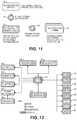
- FIG. 12is a block diagram of the personal identity vault that illustrates the major functional blocks of the invention.
- FIG. 13is a block diagram of a powered card as a secondary device with major functional blocks of the invention including a dynamic magnetic stripe module.
- FIG. 14describes areas where pinch conductive material can be applied to both sides of a powered card to achieve pinch power, a method to turn on a powered card by completing a circuit as a user naturally holds the card.
- FIG. 16illustrates a pinch power prototype with transparent conductive material on designated areas of both sides of a card.
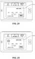
- FIG. 19describes a user interface (UI) concept for a user to access a private electronic vault by typing a user-configured PIN.
- UIuser interface
- FIG. 21describes the user interface (UI) for scrolling through user-definable categories on the private electronic vault.
- FIG. 22describes another user interface (UI) concept for a user to access categories of aliases to personal information.
- UIuser interface
- FIG. 23describes another user interface (UI) concept for a user to access preferred aliases.
- FIG. 24describes a user interface (UI) concept for a user to view details of private information such as a payment card.
- UIuser interface
- FIG. 25describes another user interface (UI) concept for a user to view details of private information such as a payment card.
- UIuser interface
- FIG. 26describes a user interface (UI) concept to manage personal information and cards within a private electronic wallet from an app on a second device, such as mobile and fixed devices like cell phones, tablets, laptops, PCs and the like.
- UIuser interface
- the present inventiondiffers from other “digital wallets” in that other wallets are more focused on solutions that rely upon an internet connection to perform card/account selection and/or transaction.
- this inventionis focused on replacing the number and variety of devices holding personal information within a physical wallet, and replication of their functionality onto a secondary authenticated device that conforms to current common communication interfaces for private methods such as HIPPA controlled communication methods for private medical documents and payment methods such as NFC or dynamic magnetic stripe.
- the first devicewhich may comprise and be referred to as an electronic vault device, personal identity vault, private electronic vault, a private electronic wallet, a secure electronic payment and identity management device, a secure electronic payment and identification device or system, a next generation payment and personal identity wallet, and a next generation payment and personal identity device, can be physically part of a physical wallet as shown for examples in FIGS. 2 and 3, 102 and 104 , insert to a wallet as shown in FIG.
- wearable/portable devicessuch as money clips, key chain accessories, watches, dongles, cell phone accessories, or any other device typically carried or worn by an individual.
- This personal identity vault devicerequires unique biometrically enabled multi-factor authentication to ensure only owners and their private information can be copied into the vault device.
- Authenticated usersmay then select credit, debit, identification, medical or virtually any private information via touch display or voice command on the first device, or alternatively on the second device that connects to the first device.
- Encrypted informationcan be then sent from the first device to the second (authenticated) device, such as a programmable card with dynamic magnetic stripe.
- the format of the information in the second deviceis selected to replicate the desired transaction method.
- the second devicecan be pre-programmed to be any card type, such as a stand-alone multi-card, or the second device can sit within the electronic wallet device, which acts as a security system for programming the dynamic card.
- Informationcan be “zeroized”, writing 1's and 0's over memory iteratively in random pattern, after one use, a preconfigured number of uses, or after a timer has expired.
- a usermay select a card via the touch interface or voice command on the first device or alternatively on an authenticated second device with display interfaces (e.g. cell phone, tablet, PC, etc.), and configure the second device to function just like a copied device.
- the first devicee.g., private vault electronic wallet device
- the authenticated second devicecan be used with other mobile payment forms such as NFC, EMV, RFID, infrared, acoustic, and QR Codes in some embodiments.
- logos, picture of the front and back, signature and even bar codescan be displayed on the sunlight readable display of the first or second devices such that secure electronic payment and identification system can uniquely support all common methods of payment currently supported at point of sale (POS) positions around the world. Other security methods such as a physical signature on the back of a payment device can also be supported.
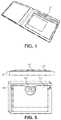
- the private electronic vaultcan encompass many embodiments spanning varying mechanical configurations. As shown in FIG. 1 , one embodiment consists of a standalone private electronic vault 100 with secondary authenticated device, in this case a powered card 101 that can be located anywhere with the vault.
- FIG. 2describes a mechanical design of the invention configured with the display of the private identity vault device embedded in the wallet and viewable on the outside of the wallet.
- a display 102that can be inserted into a wallet or embedded into an carried or worn device, a touch panel overlay 103 , a battery indicator 104 , a power on/off button 105 , a microphone with exposure through the enclosure for appropriate acoustics 106 , soft or hard material 107 appropriate for gripping the wallet and/or protecting other cards within the wallet such as blocking/attenuating signals to protect RF cards within, curved design 108 to conform to wearing in a rear or front pocket of a person's clothing, magnetic clasp 109 that keeps the wallet closed until opened, magnetic switch 110 that turns the electronic wallet on and off as the wallet is opened, an area for a secondary device 111 , a hinge or fold mechanism 112 , areas and/or folds 113 for other cards and/or receipts, and/or a money clip 114 .
- FIG. 3illustrates this concept with the display located at the left 115 or the right 116 sides of the inside of the wallet.
- FIG. 5describes the enclosure 118 of a standalone configuration that stores the display and electronics of the private electronic vault, alone with an attachment 119 that serves as a dual purpose as a storage method for a powered card 120 and an insert 119 to hold the device in place inside a pocket of a conventional wallet.
- FIG. 6Another embodiment of the mechanical design of this invention described in FIG. 6 is to not only hold a card or powered card with guide 121 and ramp 122 features, but also communicate with a powered card and charge its battery by aligning physical contacts 123 or embedded electrical components (not shown) such as antenna, coils, or the like.
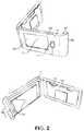
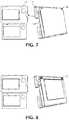
- FIG. 7Other embodiments include standalone private electronic wallet 124 with optional enclosed card 125 using molded guides 126 as shown in FIG. 7 , optional removable insert 127 as shown in FIG. 8 , an open version of the private electronic vault 128 where the molded guide is open 129 to allow easier grip to a card, and a clip may be either molded 130 or removable 131 .
- These standalone embodimentscontrast to another clamshell design as shown in FIG.
- a hard or soft case 132may still possess each of the optional features such as a hard or soft case 132 , display 133 , touch screen 134 , modern design for comfort such as tapered corners and sides 135 , microphone 136 , battery indicator 137 , power button 138 , magnetic clasp 139 and/or magnetic switch 140 , hinge 141 , card holders 142 , and/or money clip (not shown on this drawing).
- a hard or soft case 132display 133 , touch screen 134
- modern design for comfortsuch as tapered corners and sides 135 , microphone 136 , battery indicator 137 , power button 138 , magnetic clasp 139 and/or magnetic switch 140 , hinge 141 , card holders 142 , and/or money clip (not shown on this drawing).
- personal identity vaults 143may communicate to multiple secondary devices 144 and 145 with NXT approved authentication such as dynamic pairing 146 or equivalent authentication methods.
- Some second devices 144may act as a display for the personal ID vault, while other second devices 145 act as conduit to send private information over other protocols and methods not inherent to the vault.
- the hardware for the private electronic vault and one embodiment of a second device hardwaremay be similar as shown in FIGS. 12 and 13 , consisting of an ultra low-power microprocessor 147 powered by batteries or super-capacitors 148 managed by a battery monitor, input power condition, DC to DC converters, recharging circuits with optional inductive and/or RF wireless recharging circuits, all within a power management block 149 .
- the microprocessor 147acts as the microcontroller for all onboard peripherals including RAM and NAND memory 150 , or optionally FRAM and/or NVRAM (shown as part of the memory block 150 in the diagram) in some configurations.
- the microprocessor 147may interface with an optional low-power e-paper, memory LCD and/or color display 151 .
- a transparent/semitransparent touch screenmay be overlaid atop the display 152 , in some configurations, and optionally wired directly to an analog comparator module within the microprocessor for ultimate low power performance while filtering and interpreting touch events, or replaced with physical buttons (not shown) outside of the display for user interface controls.
- the vaultalso contains a multi-factor voice recognition algorithm via voice collected by an onboard microphone that connects directly to dual stage amplifiers within the processor for filtering and amplifying the voice. Amplifiers within the processor further reduce power consumption and chip count/cost.
- Both devicesmay also communicate via contacts 123 , USB 154 or optional wireless communication including BTLE (Bluetooth Low Energy) 155 , NFC/EMV 156 , RFID 157 , infrared 158 , optical 159 , WiFi 160 , acoustic 161 , or custom low-power RF communication (not shown).
- BTLEBluetooth Low Energy
- NFC/EMV 156NFC/EMV 156
- RFID 157infrared 158
- optical 159optical 159
- WiFi 160acoustic 161
- custom low-power RF communicationcustom low-power RF communication (not shown).
- other biometricsmay be optionally added including gesture, finger, face, 3D face, IRIS, eye, eye vein, eye tracking, DNA, vein, palm, heartbeat, sweat, vibrometry, and/or scent by adding those sensors to the interface of the microprocessor.
- Microprocessors on each devicemay also integrate with a tamper-proof authentication crypto chip 153 , which houses identifiers, high quality random number and key generators internally such that no keys or identifiers are ever released by the authentication chip. Only random numbers are ever passed over encrypted communicated between the first and second devices.
- the second devicemay provide a conduit to transfer the private information over some specific payment or transfer methods that exist on the second device.
- some commercial devicesmay support various communication methods such as WiFi or NFC, negating the need for the next generation payment and personal identity wallet to support these methods directly on its device.
- the private electronic vault device(the first device) may simply communicate to the second device that then acts as a conduit to adhere to any communication standards from authorities that dictate the transfer of private information, such as HIPPA or financial authorities.
- the second device(s)may comprise any mobile, portable, or wearable device such as cell phones, tablets and the like, or even fixed computing devices such as PCs.
- the second devicecan contain similar components (in function), but not necessarily the exact same chip as that with the primary electronic vault, such as a crypto chip 153 , ultra low-power processor 147 , flash memory, SDRAM, FRAM or NVRAM (collectively part of the memory block of the diagram), display 151 and touch screen 152 , battery 148 and power management 149 , crypto 153 , microphone 162 , biometric modules 162 and communications methods such as USB 154 , BTLE 155 , NFC/EMV 156 , RFID 157 , infrared 158 , optical 159 , WiFi 160 , acoustic 161 , or custom low-power RF communication (not shown).
- a crypto chip 153such as a crypto chip 153 , ultra low-power processor 147 , flash memory, SDRAM, FRAM or NVRAM (collectively
- These second devices powered cards 165may also include a dynamic magnetic stripe module 164 to interface with mag stripe card readers using a powered card.
- each of the componentsmay be wired thinner versions of these chips, wafer or die formats 0.5 mm or thinner, in order to conform to ISO standards for payment cards of approximately 0.79 mm or thinner). Displays on these cards may also be thinner and can include other ultra thin displays that shows the payment account number 166 , in whole or in part, and other information such as CVV 167 , name 169 and expiration date 168 as shown in FIG. 14 .
- Battery and/or super-capacitorsare continuously monitored by power management 149 at a predetermined time interval to activate a “low-battery” indicator (LED or equivalent shown as part of the Power Management block 149 ) when power is measured to be below a specific threshold.
- a rechargeable circuitshown as part of block 149 ) allows power to be recharged when connected to a 5 VDC USB device, or alternatively to be recharged via optional wireless inductive or RF charging methods, or other power harvesting methods such as solar/light, RF, piezoelectric/movement and thermal (each shown as part of the power management block 149 on the block diagram).
- a second devicesuch as a dynamically programmable card
- the private electronic vaulti.e., the first device
- the dynamically programmable cardis near the private vault device, such as within a wallet.
- An optional wireless inductive ultra thin coil (shown as part of block 149 ) associated circuitryenables the primary device to communicate and charge the second device(s) using inductive charging conforming to the 01 interface standard for inductive electrical power transfer.
- the microprocessorcan be held at various “power states” that turn off the core processor and all peripherals except the a GPIO pin that can be used to wake up from “deep sleep”.
- Other power statesinclude keeping the core off while interfaces to peripherals on. This enables DMA (direct memory access) transfers from one peripheral, such as memory, to another peripheral, such as the display, with minimum involvement (and power) by the processor. This allows the microprocessor to be kept at its lowest states and “wake-up” to other states only when the core processor is needed. This schema achieves lower power performance by “ping-ponging” between power states only as resources on the ultra low power microprocessor are needed.
- Another unique power reduction featureis to power peripherals of the microcontroller directly from GPIO (general purpose input output) pins such that any peripheral can be powered on or off directly by the microprocessor.
- GPIOgeneral purpose input output
- the microprocessor“wakes up” that peripheral by turning on the appropriate GPIO pin. Powering the peripherals directly by the microprocessor in this manner not only reduces needless power consumed while a peripheral is not used (e.g. in a quiescent state), but also reduces chip count by eliminating DC supplies.
- Conductive regions 170can be achieved either by exposing a conductive material 172 that connects to the inlay or using a transparent/semi-transparent conductive spray 179 as part of the lamination of the card that then touches electrical “posts” or conductive areas that are exposed during the manufacturing process (exposed copper or equivalent material that connects to the inlay much like smart cards such as contact EMV).
- the materialis then wired to the circuit and battery 180 .
- a circuitis completed when both sides of the card are touched with a conductive material, such as fingers or for the purposes of this prototype, pliers 181 .
- Conductive translucent coatingsare available for use on the typical card PVC material. This method reduces power consumption of powered cards, while simplifying the user experience and reducing the chance of a powered card turning on accidently within a pocket or wallet.
- the switched outputWhen power is first applied to the circuit, the switched output is not active. When the user completes the circuit by pinching in the conductive regions on both sides of the card, the output becomes active and is latched. If nothing touches the conductive regions on both sides of the card, the circuit will continue to output power until a timer is completed by the microprocessor, or unless both of the conductive planes are shorted again (e.g. the user pinches the powered card on conductive regions on both sides of the card). Upon initial power-up of the microprocessor, the microprocessor control pin is set to an input state. This allows for detection of additional touches of the conductive planes. When the card has finished its task, or a timeout condition occurs, the microprocessor can set the microprocessor control pin to an output, and an active low state will reset the latching circuit to a powered down state.
- the second device 190must authenticate with the private electronic vault (first device 189 ) before any information is passed or transaction performed. As shown in FIG. 17 , two devices are dynamically paired when a random number 185 output from a high-quality random number generator 184 from within one device is input to the crypto chip 153 of the second device, and a SHA256 hash is generated by a key generator 183 between the random number 185 and some combination of the various identifiers 186 .
- the generated pseudorandom number response 190is then sent back to the first device, where it is compared by an internal comparator 182 with a SHA256 hash 193 of the same pseudorandom number generated 192 as that was challenged 185 and the same internal identifiers 191 , all within the crypto chip 153 onboard the first device. If the two numbers match, the devices are authenticated.
- a one-time-use encryption keymay be generated between devices in the same manner as authentication, in order to encrypt and store credit card numbers, names, and other private information on the private electronic vault.
- the temporary keymay be stored in a temporary memory slot 188 within the crypto chip 153
- the vaultthen sends encrypted data to the second device via a wireless communication link, where the encrypted data is decrypted via its internal one-time-use encryption key and then sent by the second device via the appropriate transaction method.
- the transaction methodis a common point of sale (POS) that utilizes magnetic stripe techniques
- the second devicemay be a powered card with a reprogrammable dynamic magnetic stripe 163 .
- the second deviceacts as a conduit to support virtually any method of payment or communications.
- Dynamic codesare generated from combination of one or more unique identifiers and/or keys 187 that are specific to factors including but not limited to users, manufacturers, devices, accounts, locations and/or sessions or transactions.
- Identifiers that may be used within the dynamic pairing methodinclude biometrics, proximity sensors, user “secrets” (Passwords/PINs/etc.), manufacturer ID, wallet ID, master encryption key, user customizable card names, card type, device serial number, electrical noise ID, CRC, MAC address, CVV, charge limits and time duration.
- a high-quality random number generator 184 , Identifiers 187 , embedded key generator 183 , and comparator 182are all safely hidden within the tamper-proof crypto chip 153 at all times. Even the proprietary dynamic pairing code algorithm used to generate the dynamic pairing codes may be stored in a tamper-proof crypto chip 153 as well, so that no information is ever available to be hacked.
- the algorithm that generates the dynamic pairing codeuses different combinations of these identifiers during different data sequences or at different time instances in combination with a high quality random number generator 184 local on the same protected crypto chip 153 so that identifiers 187 saved on the device are never externally accessible.
- the combination of which identifiers are used and when they are usedis based upon a proprietary NXT-ID (assignee of the present invention) algorithm. Thus, only the generated random number and its response are ever shared between the first and second devices.
- Any second devicesuch as the dynamic card or even a cell phone, may be authenticated via dynamic pairing or equivalent method that sends a high quality random number 185 as a challenge to the other device, and compares the response 190 with its internally generated result.
- authentication codesmay be generated by a SHA256 generator within software, or for more security for cell phone and other remote applications, the app can be in the middle of the 2 devices, where the app communicates from one device through the app to another device to ensure security at all times, even in demanding remote applications
- Challenge/response methods of authenticationsuch as dynamic pairing have a distinct advantage of performing multi-factor authentication by passing only pseudorandom numbers, without revealing any identifiers or keys. Furthermore, having the pseudorandom number generator, comparator and the key generator within the same tamperproof device that also holds the identifiers ensures all secrets are kept secure during authentication and encryption key generation.
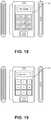
- Usersmay access the private electronic vault by responding correctly to the authentication question from the vault. Questions could be preconfigured by the user or random. A user may be asked to speak a certain word via a microphone 162 , or provide a pattern 194 as shown in FIG. 18 , password or pattern 195 as shown in FIG. 19 .
- Voiceis a unique biometric in that a user may speak a typed word and a VoiceMatchTM algorithm that will recognize both the speaker and the word.
- the usermay simply give a spoken word correlated with specific private information, like a payment account or medical record.
- the private electronic vaultwill perform multi-factor authentication on this word by recognizing the speaker and the word itself.
- the wordis then recognized as associated with the private information, and that information can then be sent to the second device. Additional security protection may be put in place, as a user desires, to require another authentication to display private data on the device.
- the standard communication interface to the devicesis BTLE (or for second devices, just simple Bluetooth), but the devices can also support other optional interfaces such as USB, or wireless interfaces such as NFC, RFID, infrared, optical acoustic, or WiFi.
- these interfacesmay be used by applications on the authenticated second device to communicate and control the private electronic wallet to add, delete, modify, manage and receive private information for some transaction.
- Private information that can be downloaded to the private electronic walletmay consist of payment, loyalty, identity, health, medical, or just about any information found within a typical wallet.
- Non-private informationsuch as advertisements, coupons, shopping lists and the like may also be transferred to the private electronic wallet.
- informationmay be scanned directly into the private electronic vault from a Square reader (a well known magnetic strip reader for mobile platforms), USB or Bluetooth standard magnetic strip reader for added security.
- One advantage to this architecture of the private electronic vaultis its standalone feature where all interfaces are controlled via end-to-end authentication and encryption so that no hacking can be achieved even when connected to other, more vulnerable devices such as cell phones and PCs (i.e., the second device of the system of the invention).
- a usermay submit all money-related cards to an approval process upon initial use, where the identity of the individual and the card are validated, and store the bio key in a personal vault remotely.
- the authentication keyprevents other users from using the private electronic vault to program any new secondary devices. Only private information, such as payment accounts, approved by the approval process can be used by the electronic vault and dynamic card. Note, library, club membership cards and the like need not be approved if not desired by the user.
- anyone trying to make a card from another individual's private electronic vaultwould have to follow the same authentication process and therefore would be caught.
- authoritiescan be notified to pursue the attempted clone. Combining this with other methods such as timeouts and/or number or type of products to be purchased further reduces theft and fraud.
- Private Information SelectionOnce private information is scanned or entered via the validation process, users may correlate the data to user-selected word(s) that act as aliases for the protected private information. These word(s) may be spoken and/or typed for security purposes. Alternatively, a user may also enter other biometrics 163 and user secrets as options to the private identity and payment vault to add further security to the user authentication process.
- a usermay wish to correlate “green gas card #3” to represent his or her Chase Visa credit card that he or she uses for payments for gasoline.
- a userwants this payment account, he or she would simply press the on button to activate the private electronic wallet and speak the previously recorded word representing the user's associated private information (in this instance, his or her payment account associated with his or her Chase Visa credit card).
- the word that the user speaksis then analyzed and compared to the previous word using a voice recognition algorithm internal to the private electronic vault. This algorithm identifies both the speaker and the word, and then programs the second (or payment) device with the Chase Visa credit card information and/or displays the information to a display on the local device as previously configured by the user.
- FIG. 20describes the user interface (UI) 196 for the private electronic vault where users may select from user-configured aliases 198 that associate to some personal information within some user-configured categories 197 that has been stored to the vault.
- This user interfaceenables users to slide through a number of aliases 198 using a sliding gesture and/or buttons.
- the number of aliases(associated to captured personal information) is only limited by the memory configured on the device (defaults to 100 cards, but can support higher numbers with a larger memory chip).
- the user interfacemay scroll through user-definable categories 200 on the private electronic vault where users may select a category of aliases 199 .
- This menuis activated by pressing the “menu” button 199 (whose icon is obvious to those that have used current cell phone app technology), or by sliding left or right to open or close the menu.
- This appmay also be applied to other second devices that are authenticated.
- a usermay select the alias 198 by sliding through categories 199 , selecting the appropriate category 200 the word(s) associated with the alias 198 , or sliding through all categories 200 and aliases 198 on the vault; the vault then programs an authenticated second device, which in turn programs its internal programmable magnetic stripe.
- the aliascould be selected by speaking into an application on an authenticated second device such as a cell phone, which then in turn commands the private electronic vault to select the appropriate alias and programs the authenticated second device with the programmable magnetic strip.
- FIG. 22Another user interface (UI) concept for a user to access categories 201 of aliases to personal information is shown in FIG. 22 , while FIG. 23 describes another concept for a user to access preferred 202 aliases.
- FIGS. 24 and 25illustrate a user interface (UI) concept for a user to view details 203 and 204 of private information such as a payment card.
- personal information and cards securely hidden within a private electronic walletmay be managed from an app on a authenticated second device, such as mobile and fixed devices like cell phones, tablets, laptops, PCs and the like.
- a user interfacepersonal information, such as payment cards, may be represented by logos, card pics, or other art 205 that a user may select from a browser 206 .
- Settings 207 for each cardmay include alias names, transaction limits, etc.
- Categories 209may also be programmed and loaded onto the private electronic wallet from an authenticated app on a second device. From this management UI, a user may search various categories such as cards, coupons, receipts, etc.
- private informationis totally under the owner's control on the private electronic vault.
- the usermay choose to display the private information on the private electronic vault itself, or send the private information from the vault itself using supported payment and/or communication methods optionally installed on the vault such as BTLE, NFC, dynamic magnetic stripe, EMV, QR and bar codes, infrared, acoustic, or WiFi.
- the userhas the added flexibility to interface to other authenticated second devices that then act as a conduit for the private information to be used to interface with other payment or communication methods.
- private information on the second deviceis zeroized by iteratively writing random ones and zeros over memory to make the second device “dumb” again and ensure all private information is destroyed. In this way, all private information is preserved 100% of the time as the second devices act as controls and/or conduits for the private information to support various communication and payment methods.
- SecurityOne advantage of the approach of the various presented embodiments is security. Users can program the devices with any combination of the following security features:
- the private electronic vaulti.e., the first device
- the second devicemust both be present for any transaction to take place. Pairing the device(s) reduces theft and fraud by requiring both devices to be present and authenticated with one another prior to any transaction that accesses private information. This significantly limits the ability of thieves to clone cards, for instance, since both devices must be present to program the first device (electronic vault), and they are further protected with a key derived from the combination of methods described.
- the usermay additionally set further limitations before the transaction takes place. Users can select any or a combination of methods including biometrics, proximity sensors, time out periods, maximum dollar amount, number of transactions, type of transactions, or user selected products that are allowed to be purchased. If these limitations are exceeded, the devices immediately detect the anomaly and theft or fraud can be prevented, and authorities can be notified.
- the methods of the present inventioncan also be extended to other mobile devices acting as the private electronic wallet. These methods may also be extended such that a mobile device authenticates directly to a second device, such as a dynamic magnetic stripe card.
- a severed configurationis advantageous, given it significantly reduces the vulnerabilities that still plague the mobile wireless device industry by providing a standalone, separate device that is virtually hack proof.
- the private electronic walletcan be used standalone or tethered to mobile or fixed devices such as a cell phone or PC and driven by third party apps and user interfaces on those devices. Security is maintained at all times by use of dynamic pairing or equivalent authentication and encryption between the private electronic vault and any of these second devices such as PCs, mobile devices and/or programmable dynamic stripe card.
- Basic configurations of the private electronic vaultsupport BTLE to configure and validate the user.
- Other configurationsinclude USB and wireless configurations such as NFC (Near Field Communications), RFID, WiFi, 3G/4G/LTE and Bluetooth, although each of these configurations has separate wireless security profiles.
Landscapes
- Engineering & Computer Science (AREA)
- Business, Economics & Management (AREA)
- Accounting & Taxation (AREA)
- Theoretical Computer Science (AREA)
- Physics & Mathematics (AREA)
- General Physics & Mathematics (AREA)
- Finance (AREA)
- Computer Networks & Wireless Communication (AREA)
- Strategic Management (AREA)
- General Business, Economics & Management (AREA)
- Health & Medical Sciences (AREA)
- Bioethics (AREA)
- General Health & Medical Sciences (AREA)
- Medical Informatics (AREA)
- Databases & Information Systems (AREA)
- Computer Hardware Design (AREA)
- Computer Security & Cryptography (AREA)
- Software Systems (AREA)
- General Engineering & Computer Science (AREA)
- Storage Device Security (AREA)
- Financial Or Insurance-Related Operations Such As Payment And Settlement (AREA)
- Credit Cards Or The Like (AREA)
Abstract
Description
- How to turn them on and off without cumbersome switches.
- How to keep them from turning on when placed in areas that could activate a “switch” mechanism, such as a wallet, and thus needlessly drain the battery.
- 1. Name variation embedded in the private electronic vault
- 2. Validation process of payment cards prior to scanning.
- User to Vault: Regardless if an authenticated second device is used or not, all users must be authenticated to the private electronic vault (the first device) using one of the following methods:
- a.
Biometrics 163 ofFIG. 12 : A biometric, such as voice, entered by the user matches that entered during setup (Note: Biometrics can include voice, gesture, finger, face, 3D face, IRIS, eye, eye vein, eye tracking, DNA, vein, palm, heartbeat, sweat, vibrometry, and/or scent by simply adding those sensors to the interface of the microprocessor). - b. PIN or Password: A PIN or password entered by the user matches that entered during setup.
- c. Pattern: A pattern drawn on the screen matches that entered during setup.
- d. Signature: The signature entered by the user matches that which was written on the rear and/or display of the device(s).
- a.
- Private Data to Vault (i.e., the first device): Name variation embedded on the private electronic vault must match that scanned by any private information being input from certain types of cards such as payment, medical, and identity cards.
- Card to a Card Company: The card is approved as valid by a financial or other institution providing the card.
- Two paired devices: The two paired devices must be stolen under certain embodiments, not just the wallet.
- a. Pairing: The second device(s) are dynamically paired to a specific private electronic vault.
- b. Proximity: The second device(s) close proximity with a paired private electronic vault.
- c. Name etching: A name may be permanently etched onto the private electronic vault (also referred to as the first device) to match other forms of identification of the user.
- d. CVV, Names, Numbers and/or Expiration Dates: CVV, names, numbers and/or expiration dates may be displayed on the device(s).
- e. Charge limits: The transaction does not exceed the amount limit set by the owner of the private information.
- f. Time duration: The time duration for a transaction or account does not exceed that set by the owner of the private information.
- h. Dynamic Authentication and Encryption keys: One-time use authentication and encryption keys that are generated dynamically based on the time of day and/or sequence, and/or a combination of the identifiers.
- User to Vault: Regardless if an authenticated second device is used or not, all users must be authenticated to the private electronic vault (the first device) using one of the following methods:
- A separate solution dedicated to the purpose of an electronic wallet, versus cell phones and other mobile devices that are multi-purpose.
- Two separate devices that must be “dynamically paired” to each other.
- Sufficiently small to support a number of different configurations, including:
- Part of the physical wallet or standalone wallet insert
- Money clip
- Key chain accessory
- Watch
- Dongle
- Cell Phone accessory
- or any other device typically carried by an individual.
- Support the most common forms of payment today:
- Magnetic Stripe
- NFC
- EMV
- QR Codes
- RFID
- In other embodiments, infrared, acoustic, Bluetooth Low Energy (BTLE), WiFi, 3G/4G/LTE and cloud based payment forms are also supported.
- Replication of all cards and other information frequently found within a typical physical wallet, not just payment cards, including:
- Payment cards
- Credit
- Debit
- ATM
- Gift
- Cash
- Calling
- Loyalty cards
- Shopping (Restaurants, Retail, etc.)
- Frequent Flyer
- Reward Cards
- Club/Membership cards
- Shopping (BJ's, Sam's Club, etc.)
- Organizations/Affiliations (IEEE, etc.)
- Social
- Library
- Hotel
- Rental Car
- Vacation
- Roadside assistance
- Identity
- Licenses
- Passports
- Visas
- Voter's Registration
- Employee
- Security
- Passcards
- Business Cards
- Insurance
- Auto
- Health/Medical
- Dental
- House
- Life
- Travel
- Medical Records Cards
- Conditions
- Medications
- Hospitalization
- Shopping lists
- Discount
- Coupons
- Receipts
- Tickets
- Payment cards
- Enhanced Security features including:
- User to Vault
- Private Information to Vault
- Card to Card Company
- Two Separate Dynamically Paired devices as described herein
- Pairing of external devices to the first device (the private electronic wallet)
- Proximity
- PIN or Password
- Pattern
- Signature
- Name etching
- CVV
- Biometric enabled generated keys
- Charge limits
- Time duration
- Dynamic authentication and encryption keys (based on dynamic combinations of information listed above).
- Receipts (Pocket Accountant)
- Automatic Receipt Coding and Book Keeping
- Shopping List
- Shopping Assistant (Shopper and/or Retail Aisle Assistant
- Ads/Specials/Coupons
- Proximity Based Ads/Specials/Coupons
- RFID Ads/Specials/Coupons
- Proximity Cards
- Toll Attendant
- Money (Wires)
- Payment
- 24 hour Replacement Service
- Travel Service.
- Receipts (Pocket Accountant): For transactions that utilize 2-way communications with servers, such as wireless/contactless methods such as NFC, RFID, WiFi and 3G/4G/LTE, transactions can be recorded directly to the first device (private electronic wallet) so that it acts as a “pocket accountant”. Within this embodiment of this invention, information regarding the card such as balances can also be displayed with each soft-card.
- Automatic Receipt Coding and Book Keeping: For transactions that utilize 2-way communications with servers, such as wireless/contactless methods such as NFC, RFID, WiFi and 3G/4G/LTE, transactions can be also automatically recorded, coded, sorted and output to third party programs such as excel and QuickBooks. Within this embodiment of this invention, information regarding the transactions of a card can be automatically output to business accounting tools.
- Shopping List: Products can be typed, scanned or electronically obtained on a PC or mobile device, and downloaded to the Wocket™ to be used at a retail location.
- Shopping Assistant (Wocket™ Shopper and/or Retail Aisle Assistant): This invention detects RFID enabled products as a shopper strolls down a retail aisle and notifies the shopper of any product that matches an item on a shopping list previously downloaded to the private electronic wallet or vault, commercially referred to as the Wocket™)
- Ads/Specials/Coupons: This invention consists of advertisements, specials and coupons can be typed, scanned or electronically obtained on a PC, then managed on the PC, and downloaded to the private electronic wallet or vault to be used at a retail location. Coupons can then be retrieved on the private electronic wallet during shopping, and the bar code displayed for each coupon on the private electronic wallet e-paper, mLCD or low power color display. This display is advantageous since bar codes can be reliably scanned on this display (where they cannot on typical LCD displays on cell phones, for instance). These coupons can also be associated with optional shopping lists also managed and downloaded to the primary electronic vault.
- Proximity Based Ads/Specials/Coupons: This embodiment consists of advertisements, specials and coupons that can be automatically offered to the shopper (user) based upon the store the user enters. The store location is detected by the private electronic vault via optional integrated GPS module, or via wireless integration with a user's cell phone.
- RFID Ads/Specials/Coupons: This embodiment consists of advertisements, specials and coupons that can be automatically sent to the vault from the retail item itself as a shopper passes within range of the RFID of the specific retail item (or product). The shopper can then be notified of “specials” (coupons) that can be used with the product.
- Proximity Cards: Cards can be automatically offered to the shopper (user) based upon the store the user enters. In this embodiment the store location is detected by the vault via optional integrated GPS module, or via wireless integration with a user's cell phone. The best cards are offered to the shopper based on calculating which card provides the best benefits for a given store or list of purchases.
- Toll Attendant: The private electronic vault is also integrated with novel RFID that can be used as a passive mobile “Toll” payment method. The toll attendant service automatically interfaces with the same RFID technology of the E-ZPass Interagency Group (IAG), which comprises 25 agencies spread across 14 states.
- Money (Wires): This service enables the private electronic wallet to transfer money to one another via a wallet to wallet validation process. Once validated, payments can take place between two parties with proper authentication of each of their respective Wockets.
- Payment: The embodiment of this invention enables a private electronic wallet to accept payments. Consumers can pay for items via their typical payment method including magnetic stripe, NFC, contactless EMV, and QR Codes. The private electronic wallet can be configured to accept these forms of payment with connected or disconnected methods of validation (wireless payment validation and/or pre-authorization via housing each of the cards prior to transaction (so that they can be held securely until the validation process can be performed)).
- 24 hour Replacement Service: This embodiment provides an optional service to users to replace the private electronic wallet by calling the service number, validating the user's identity, and sending a new Wocket with all cards that have been placed by the user on the secure server
- Travel Service: This embodiment comprises an optional service that enables users to notify card companies of cards on a specific private electronic wallet of impending travel plans, to prevent the card company from calling the user to validate purchases as the user travels.
Claims (20)
Priority Applications (1)
| Application Number | Priority Date | Filing Date | Title |
|---|---|---|---|
| US16/005,598US10679209B2 (en) | 2012-10-08 | 2018-06-11 | Method for replacing traditional payment and identity management systems and components to provide additional security and a system implementing said method |
Applications Claiming Priority (3)
| Application Number | Priority Date | Filing Date | Title |
|---|---|---|---|
| US201261710826P | 2012-10-08 | 2012-10-08 | |
| US14/049,175US20140108241A1 (en) | 2012-10-08 | 2013-10-08 | Method for Replacing Traditional Payment and Identity Management Systems and Components to Provide Additional Security and a System Implementing Said Method |
| US16/005,598US10679209B2 (en) | 2012-10-08 | 2018-06-11 | Method for replacing traditional payment and identity management systems and components to provide additional security and a system implementing said method |
Related Parent Applications (1)
| Application Number | Title | Priority Date | Filing Date |
|---|---|---|---|
| US14/049,175ContinuationUS20140108241A1 (en) | 2012-10-08 | 2013-10-08 | Method for Replacing Traditional Payment and Identity Management Systems and Components to Provide Additional Security and a System Implementing Said Method |
Publications (2)
| Publication Number | Publication Date |
|---|---|
| US20190139030A1 US20190139030A1 (en) | 2019-05-09 |
| US10679209B2true US10679209B2 (en) | 2020-06-09 |
Family
ID=50476294
Family Applications (3)
| Application Number | Title | Priority Date | Filing Date |
|---|---|---|---|
| US14/049,175AbandonedUS20140108241A1 (en) | 2012-10-08 | 2013-10-08 | Method for Replacing Traditional Payment and Identity Management Systems and Components to Provide Additional Security and a System Implementing Said Method |
| US15/252,468Active2034-11-19US10269010B2 (en) | 2012-10-08 | 2016-08-31 | Method for replacing traditional payment and identity management systems and components to provide additional security and a system implementing said method |
| US16/005,598Active2033-11-09US10679209B2 (en) | 2012-10-08 | 2018-06-11 | Method for replacing traditional payment and identity management systems and components to provide additional security and a system implementing said method |
Family Applications Before (2)
| Application Number | Title | Priority Date | Filing Date |
|---|---|---|---|
| US14/049,175AbandonedUS20140108241A1 (en) | 2012-10-08 | 2013-10-08 | Method for Replacing Traditional Payment and Identity Management Systems and Components to Provide Additional Security and a System Implementing Said Method |
| US15/252,468Active2034-11-19US10269010B2 (en) | 2012-10-08 | 2016-08-31 | Method for replacing traditional payment and identity management systems and components to provide additional security and a system implementing said method |
Country Status (1)
| Country | Link |
|---|---|
| US (3) | US20140108241A1 (en) |
Cited By (1)
| Publication number | Priority date | Publication date | Assignee | Title |
|---|---|---|---|---|
| US20240119455A1 (en)* | 2016-07-22 | 2024-04-11 | Wells Fargo Bank, N.A. | Piezoelectric biometric card security |
Families Citing this family (69)
| Publication number | Priority date | Publication date | Assignee | Title |
|---|---|---|---|---|
| US20120252360A1 (en)* | 2011-03-29 | 2012-10-04 | Research In Motion Limited | Mobile wireless communications device for selecting a payment account to use with a payment processing system based upon a microphone or device profile and associated methods |
| GB201105765D0 (en) | 2011-04-05 | 2011-05-18 | Visa Europe Ltd | Payment system |
| US9792035B2 (en)* | 2012-10-09 | 2017-10-17 | Mastercard International Incorporated | System and method for payment using a mobile device |
| KR20150072438A (en)* | 2012-10-15 | 2015-06-29 | 파워드 카드 솔루션스, 엘엘씨 | System and method for secure remote access and remote payment using a mobile device and a powered display card |
| US8972296B2 (en)* | 2012-12-31 | 2015-03-03 | Ebay Inc. | Dongle facilitated wireless consumer payments |
| US20130290427A1 (en)* | 2013-03-04 | 2013-10-31 | Hello Inc. | Wearable device with unique user ID and telemetry system in communication with one or more social networks |
| FR3008518B1 (en)* | 2013-07-11 | 2017-03-24 | Compagnie Ind Et Financiere Dingenierie Ingenico | Method of realization, terminal and corresponding computer program. |
| US20150023572A1 (en)* | 2013-07-22 | 2015-01-22 | Rocky Williform | System and methods for providing finger vein authentication and signature for execution of electronic wallet transactions |
| US9445220B2 (en)* | 2013-09-06 | 2016-09-13 | Paypal, Inc. | Systems and methods for enabling additional devices to check in to bluetooth low energy (BLE) beacons |
| US9356819B2 (en) | 2013-09-27 | 2016-05-31 | Ebay Inc. | Systems and methods for checking a user into a location using a packet sequence including location information |
| GB2519766A (en)* | 2013-10-29 | 2015-05-06 | Mastercard International Inc | A system and method for disseminating functionality to a target device |
| EP4057203A1 (en) | 2013-12-19 | 2022-09-14 | Visa International Service Association | Cloud-based transactions methods and systems |
| US9922322B2 (en) | 2013-12-19 | 2018-03-20 | Visa International Service Association | Cloud-based transactions with magnetic secure transmission |
| US10846694B2 (en) | 2014-05-21 | 2020-11-24 | Visa International Service Association | Offline authentication |
| US9881303B2 (en) | 2014-06-05 | 2018-01-30 | Paypal, Inc. | Systems and methods for implementing automatic payer authentication |
| US9225695B1 (en)* | 2014-06-10 | 2015-12-29 | Lockheed Martin Corporation | Storing and transmitting sensitive data |
| US10430789B1 (en) | 2014-06-10 | 2019-10-01 | Lockheed Martin Corporation | System, method and computer program product for secure retail transactions (SRT) |
| EP2961209A1 (en)* | 2014-06-25 | 2015-12-30 | Thomson Licensing | Method and device for pairing devices |
| GB2528486A (en)* | 2014-07-23 | 2016-01-27 | Valasca Ltd | Verification method and system for digital currency |
| KR102287160B1 (en)* | 2014-07-31 | 2021-08-06 | 엘지전자 주식회사 | The wearble device and control method thereof |
| US9775029B2 (en) | 2014-08-22 | 2017-09-26 | Visa International Service Association | Embedding cloud-based functionalities in a communication device |
| US10453053B2 (en)* | 2014-09-02 | 2019-10-22 | Fit Pay, Inc. | Systems and devices for wireless charging of a powered transaction card and embedding electronics in a wearable accessory |
| US10902423B2 (en) | 2014-09-29 | 2021-01-26 | Mastercard International Incorporated | Method and apparatus for streamlined digital wallet transactions |
| WO2016068925A1 (en)* | 2014-10-30 | 2016-05-06 | Hewlett-Packard Development Company, L.P. | Access medium |
| US20160156603A1 (en)* | 2014-11-28 | 2016-06-02 | Craig Janik | Low Power Secure User Identity Authentication Ring |
| US11295291B2 (en)* | 2014-12-24 | 2022-04-05 | Paypal, Inc. | Low battery and digital wallet |
| US20160277383A1 (en)* | 2015-03-16 | 2016-09-22 | Assa Abloy Ab | Binding to a user device |
| US11736468B2 (en)* | 2015-03-16 | 2023-08-22 | Assa Abloy Ab | Enhanced authorization |
| US20160335608A1 (en)* | 2015-05-15 | 2016-11-17 | Bank Of America Corporation | Virtual Payment Device Including a Scannable Code |
| US11329683B1 (en) | 2015-06-05 | 2022-05-10 | Life365, Inc. | Device configured for functional diagnosis and updates |
| US10185513B1 (en) | 2015-06-05 | 2019-01-22 | Life365, Inc. | Device configured for dynamic software change |
| US9974492B1 (en)* | 2015-06-05 | 2018-05-22 | Life365, Inc. | Health monitoring and communications device |
| US10560135B1 (en) | 2015-06-05 | 2020-02-11 | Life365, Inc. | Health, wellness and activity monitor |
| US20170061461A1 (en)* | 2015-08-26 | 2017-03-02 | Paypal, Inc. | Secondary device communications for intelligent selection of electronic sources |
| US10388411B1 (en) | 2015-09-02 | 2019-08-20 | Life365, Inc. | Device configured for functional diagnosis and updates |
| US20170344977A1 (en)* | 2016-05-31 | 2017-11-30 | The Watchtower Company | Smart Wallet |
| EP3482337B1 (en) | 2016-07-11 | 2021-09-29 | Visa International Service Association | Encryption key exchange process using access device |
| US20180060551A1 (en)* | 2016-08-23 | 2018-03-01 | Lenovo (Singapore) Pte. Ltd. | Using gas chromatography for authentication, advertisements, and therapies |
| US10225243B2 (en)* | 2016-09-30 | 2019-03-05 | Palo Alto Networks, Inc. | Intercept-based multifactor authentication enrollment of clients as a network service |
| US10701049B2 (en) | 2016-09-30 | 2020-06-30 | Palo Alto Networks, Inc. | Time-based network authentication challenges |
| US10547600B2 (en) | 2016-09-30 | 2020-01-28 | Palo Alto Networks, Inc. | Multifactor authentication as a network service |
| US10367784B2 (en) | 2016-09-30 | 2019-07-30 | Palo Alto Networks, Inc. | Detection of compromised credentials as a network service |
| SG10201608491QA (en) | 2016-10-11 | 2018-05-30 | Mastercard Asia Pacific Pte Ltd | Method And Device For Digital Payment Transactions |
| WO2018127741A1 (en)* | 2017-01-05 | 2018-07-12 | Gahlaut Shikhar | System and method for conducting electronic transactions through personal electronic transaction card |
| WO2018134855A1 (en)* | 2017-01-23 | 2018-07-26 | Stefano Nicolis | Personal identification system, particularly for making electronic payments |
| US10733589B2 (en) | 2017-04-28 | 2020-08-04 | Square, Inc. | Point of sale device power management and under voltage protection |
| US20190080330A1 (en)* | 2017-09-08 | 2019-03-14 | Infinacom, LLC | Biometric-based transaction authentication system |
| US11042933B1 (en)* | 2017-10-17 | 2021-06-22 | Chicago Mercantile Exchange Inc. | System for processing withholding payments |
| US11257058B1 (en)* | 2017-10-30 | 2022-02-22 | Square, Inc. | Sharing output device between unsecured processor and secured processor |
| US11748743B1 (en) | 2017-12-04 | 2023-09-05 | Wells Fargo Bank, N.A. | Trust-based application to application connectivity |
| US11775672B1 (en)* | 2017-12-04 | 2023-10-03 | Wells Fargo Bank, N.A. | Trust-based application to application connectivity |
| US10970698B1 (en)* | 2017-12-08 | 2021-04-06 | Square, Inc. | Reader detection signal bypassing secure processor |
| US10796563B1 (en)* | 2018-06-26 | 2020-10-06 | Amazon Technologies, Inc. | Configuring a secondary device |
| US11093593B2 (en)* | 2018-08-20 | 2021-08-17 | Lenovo (Singapore) Pte. Ltd. | User authentication for protected actions |
| US20200074418A1 (en)* | 2018-08-28 | 2020-03-05 | Juan-Hung Wu | System for issuing and converting virtual currency in physical voucher manner and method thereof |
| CN109151515B (en)* | 2018-09-12 | 2021-11-12 | 广东乐心医疗电子股份有限公司 | Interaction system and method in performance scene |
| US11455628B2 (en)* | 2018-10-05 | 2022-09-27 | Mastercard International Incorporated | Systems and methods for facilitating network transactions based on user authentication |
| US11080580B2 (en)* | 2018-12-20 | 2021-08-03 | Ncr Corporation | Chip-based card security |
| US11195242B1 (en)* | 2019-02-27 | 2021-12-07 | United Services Automobile Association (Usaa) | Systems and methods for anonymizing transaction information |
| US10467445B1 (en)* | 2019-03-28 | 2019-11-05 | Capital One Services, Llc | Devices and methods for contactless card alignment with a foldable mobile device |
| US10963888B2 (en) | 2019-04-10 | 2021-03-30 | Advanced New Technologies Co., Ltd. | Payment complaint method, device, server and readable storage medium |
| US11935059B2 (en)* | 2019-05-31 | 2024-03-19 | Visa International Service Association | System to reduce false declines using supplemental devices |
| US11363069B1 (en) | 2019-12-12 | 2022-06-14 | Wells Fargo Bank, N.A. | Systems and methods for multiple custody using mobile devices or wearables |
| JP2021144636A (en)* | 2020-03-13 | 2021-09-24 | トヨタ自動車株式会社 | Wallet server, wallet program, and wallet system |
| CN112734419B (en)* | 2021-01-18 | 2023-07-04 | 北京极智数仓科技有限公司 | Enterprise electronic wallet management method, system and terminal supporting personal real-time payment |
| US11354555B1 (en)* | 2021-05-04 | 2022-06-07 | Capital One Services, Llc | Methods, mediums, and systems for applying a display to a transaction card |
| CN114418569B (en)* | 2022-03-29 | 2022-07-26 | 深圳市合扬智能卡科技有限公司 | Operation method and system for digital payment card |
| US12106308B2 (en)* | 2022-07-08 | 2024-10-01 | Bank Of America Corporation | Auxiliary battery power authentication system for use with an EMV contactless secure transaction card |
| WO2025095824A1 (en)* | 2023-11-01 | 2025-05-08 | Telefonaktiebolaget Lm Ericsson (Publ) | Enabling presentation of credentials |
Citations (62)
| Publication number | Priority date | Publication date | Assignee | Title |
|---|---|---|---|---|
| US5221838A (en) | 1990-12-24 | 1993-06-22 | Motorola, Inc. | Electronic wallet |
| US6026379A (en) | 1996-06-17 | 2000-02-15 | Verifone, Inc. | System, method and article of manufacture for managing transactions in a high availability system |
| US6212634B1 (en) | 1996-11-15 | 2001-04-03 | Open Market, Inc. | Certifying authorization in computer networks |
| US6250557B1 (en) | 1998-08-25 | 2001-06-26 | Telefonaktiebolaget Lm Ericsson (Publ) | Methods and arrangements for a smart card wallet and uses thereof |
| US6270011B1 (en) | 1998-05-28 | 2001-08-07 | Benenson Tal | Remote credit card authentication system |
| US20020023215A1 (en) | 1996-12-04 | 2002-02-21 | Wang Ynjiun P. | Electronic transaction systems and methods therefor |
| US20020038287A1 (en) | 2000-08-30 | 2002-03-28 | Jean-Marc Villaret | EMV card-based identification, authentication, and access control for remote access |
| US20020077993A1 (en) | 2000-12-18 | 2002-06-20 | Nokia Corporation | Method and system for conducting wireless payments |
| US20020107755A1 (en) | 2000-06-30 | 2002-08-08 | Steed David Anthony William | Server-based electronic wallet system |
| US20020143634A1 (en) | 2001-03-30 | 2002-10-03 | Kumar K. Anand | Wireless payment system |
| US20020143655A1 (en) | 2001-04-02 | 2002-10-03 | Stephen Elston | Remote ordering system for mobile commerce |
| US20020169719A1 (en) | 2001-03-31 | 2002-11-14 | First Data Corporation | Electronic identifier payment systems and methods |
| US20020179704A1 (en) | 2001-06-05 | 2002-12-05 | Ncr Corporation | Enhanced digital wallet |
| US20020191816A1 (en) | 2001-06-14 | 2002-12-19 | Michael Maritzen | System and method of selecting consumer profile and account information via biometric identifiers |
| US20030024979A1 (en) | 1999-10-26 | 2003-02-06 | First Data Corporation | Money transfer systems and methods for travelers |
| US20030044090A1 (en)* | 2001-08-28 | 2003-03-06 | Nec Corporation | Mobile terminal device |
| US20030061170A1 (en) | 2000-08-29 | 2003-03-27 | Uzo Chijioke Chukwuemeka | Method and apparatus for making secure electronic payments |
| US20030154139A1 (en) | 2001-12-31 | 2003-08-14 | Woo Kevin K. M. | Secure m-commerce transactions through legacy POS systems |
| US20040078328A1 (en) | 2002-02-07 | 2004-04-22 | Talbert Vincent W. | Method and system for completing a transaction between a customer and a merchant |
| US20050131838A1 (en) | 2003-12-10 | 2005-06-16 | Ncr Corporation | Transaction system and method of conducting a point-of-sale transaction between a merchant and a consumer using a wireless platform |
| US7059531B2 (en) | 2001-07-10 | 2006-06-13 | American Express Travel Related Services Company, Inc. | Method and system for smellprint recognition biometrics on a fob |
| US7303120B2 (en) | 2001-07-10 | 2007-12-04 | American Express Travel Related Services Company, Inc. | System for biometric security using a FOB |
| US7314165B2 (en) | 2004-07-01 | 2008-01-01 | American Express Travel Related Services Company, Inc. | Method and system for smellprint recognition biometrics on a smartcard |
| US7314164B2 (en) | 2004-07-01 | 2008-01-01 | American Express Travel Related Services Company, Inc. | System for biometric security using a smartcard |
| US7318550B2 (en) | 2004-07-01 | 2008-01-15 | American Express Travel Related Services Company, Inc. | Biometric safeguard method for use with a smartcard |
| US7325724B2 (en) | 2004-07-01 | 2008-02-05 | American Express Travel Related Services Company, Inc. | Method for registering a biometric for use with a smartcard |
| US20080059379A1 (en) | 2006-05-18 | 2008-03-06 | Icache, Inc. | Method and apparatus for biometrically secured encrypted data storage and retrieval |
| US7341181B2 (en) | 2004-07-01 | 2008-03-11 | American Express Travel Related Services Company, Inc. | Method for biometric security using a smartcard |
| US7357310B2 (en) | 2005-03-11 | 2008-04-15 | Gerry Calabrese | Mobile phone charge card notification and authorization method |
| US7363504B2 (en) | 2004-07-01 | 2008-04-22 | American Express Travel Related Services Company, Inc. | Method and system for keystroke scan recognition biometrics on a smartcard |
| US7360689B2 (en) | 2001-07-10 | 2008-04-22 | American Express Travel Related Services Company, Inc. | Method and system for proffering multiple biometrics for use with a FOB |
| US20090037173A1 (en)* | 2007-08-02 | 2009-02-05 | International Business Machines Corporation | Using speaker identification and verification speech processing technologies to activate a payment card |
| US7505941B2 (en) | 1999-08-31 | 2009-03-17 | American Express Travel Related Services Company, Inc. | Methods and apparatus for conducting electronic transactions using biometrics |
| US20090143104A1 (en) | 2007-09-21 | 2009-06-04 | Michael Loh | Wireless smart card and integrated personal area network, near field communication and contactless payment system |
| US7543738B1 (en) | 2001-07-10 | 2009-06-09 | American Express Travel Related Services Company, Inc. | System and method for secure transactions manageable by a transaction account provider |
| US7578448B2 (en) | 2001-07-10 | 2009-08-25 | Blayn W Beenau | Authorizing radio frequency transactions using a keystroke scan |
| US20090235074A1 (en) | 2008-03-11 | 2009-09-17 | Imunant S.R.L. | System and method for performing a transaction |
| US7639116B2 (en) | 2001-07-10 | 2009-12-29 | Peter D Saunders | Converting account data associated with a radio frequency device |
| US7668750B2 (en) | 2001-07-10 | 2010-02-23 | David S Bonalle | Securing RF transactions using a transactions counter |
| US7705732B2 (en) | 2001-07-10 | 2010-04-27 | Fred Bishop | Authenticating an RF transaction using a transaction counter |
| US7735725B1 (en) | 2001-07-10 | 2010-06-15 | Fred Bishop | Processing an RF transaction using a routing number |
| US7740168B2 (en) | 2003-08-18 | 2010-06-22 | Visa U.S.A. Inc. | Method and system for generating a dynamic verification value |
| US7746215B1 (en) | 2001-07-10 | 2010-06-29 | Fred Bishop | RF transactions using a wireless reader grid |
| US7761374B2 (en) | 2003-08-18 | 2010-07-20 | Visa International Service Association | Method and system for generating a dynamic verification value |
| US7810165B2 (en) | 2006-06-19 | 2010-10-05 | Visa U.S.A. Inc. | Portable consumer device configured to generate dynamic authentication data |
| US7814332B2 (en) | 2001-07-10 | 2010-10-12 | Blayn W Beenau | Voiceprint biometrics on a payment device |
| US7889052B2 (en) | 2001-07-10 | 2011-02-15 | Xatra Fund Mx, Llc | Authorizing payment subsequent to RF transactions |
| US7945238B2 (en) | 2007-06-28 | 2011-05-17 | Kajeet, Inc. | System and methods for managing the utilization of a communications device |
| US8001054B1 (en) | 2001-07-10 | 2011-08-16 | American Express Travel Related Services Company, Inc. | System and method for generating an unpredictable number using a seeded algorithm |
| US20110255133A1 (en) | 2010-04-16 | 2011-10-20 | Pablo Dominguez Pastor | External storage for imaging devices |
| USRE43157E1 (en) | 2002-09-12 | 2012-02-07 | Xatra Fund Mx, Llc | System and method for reassociating an account number to another transaction account |
| US8121942B2 (en) | 2007-06-25 | 2012-02-21 | Visa U.S.A. Inc. | Systems and methods for secure and transparent cardless transactions |
| US8121945B2 (en) | 2006-07-06 | 2012-02-21 | Firethorn Mobile, Inc. | Methods and systems for payment method selection by a payee in a mobile environment |
| US8145568B2 (en) | 2006-07-06 | 2012-03-27 | Firethorn Mobile, Inc. | Methods and systems for indicating a payment in a mobile environment |
| US8160959B2 (en) | 2006-07-06 | 2012-04-17 | Firethorn Mobile, Inc. | Methods and systems for payment transactions in a mobile environment |
| US20120191612A1 (en)* | 2010-03-02 | 2012-07-26 | Digital Life Technologies, Llc | Portable e-wallet and universal card |
| US8313037B1 (en) | 2011-07-08 | 2012-11-20 | Thomas David Humphrey | Simulated magnetic stripe card system and method for use with magnetic stripe card reading terminals |
| US8376239B1 (en) | 2011-07-08 | 2013-02-19 | Thomas David Humphrey | Method of use of a simulated magnetic stripe card system for use with magnetic stripe card reading terminals |
| US20130080322A1 (en)* | 2011-09-22 | 2013-03-28 | Marsiste ADOLPHE | Smart Electronic Wallet or Smart E-wallet |
| US8690059B1 (en) | 2013-01-20 | 2014-04-08 | George Wallner | System and method for a baseband nearfield magnetic stripe data transmitter |
| US8977569B2 (en) | 2011-09-29 | 2015-03-10 | Raj Rao | System and method for providing smart electronic wallet and reconfigurable transaction card thereof |
| US20150181410A1 (en)* | 2012-05-22 | 2015-06-25 | Simo Holdings Inc. | Remote wireless smart card, smart-card terminal unit and remote wireless smart card communication system |
Family Cites Families (2)
| Publication number | Priority date | Publication date | Assignee | Title |
|---|---|---|---|---|
| WO2013155196A2 (en)* | 2012-04-11 | 2013-10-17 | Impak Health, Llc | Ecard ecg monitor |
| US10789585B2 (en)* | 2012-09-11 | 2020-09-29 | First Data Corporation | Systems and methods for facilitating remote authorization and payment of goods via mobile commerce |
- 2013
- 2013-10-08USUS14/049,175patent/US20140108241A1/ennot_activeAbandoned
- 2016
- 2016-08-31USUS15/252,468patent/US10269010B2/enactiveActive
- 2018
- 2018-06-11USUS16/005,598patent/US10679209B2/enactiveActive
Patent Citations (93)
| Publication number | Priority date | Publication date | Assignee | Title |
|---|---|---|---|---|
| US5221838A (en) | 1990-12-24 | 1993-06-22 | Motorola, Inc. | Electronic wallet |
| US6026379A (en) | 1996-06-17 | 2000-02-15 | Verifone, Inc. | System, method and article of manufacture for managing transactions in a high availability system |
| US6212634B1 (en) | 1996-11-15 | 2001-04-03 | Open Market, Inc. | Certifying authorization in computer networks |
| US20020023215A1 (en) | 1996-12-04 | 2002-02-21 | Wang Ynjiun P. | Electronic transaction systems and methods therefor |
| US6270011B1 (en) | 1998-05-28 | 2001-08-07 | Benenson Tal | Remote credit card authentication system |
| US6250557B1 (en) | 1998-08-25 | 2001-06-26 | Telefonaktiebolaget Lm Ericsson (Publ) | Methods and arrangements for a smart card wallet and uses thereof |
| US7505941B2 (en) | 1999-08-31 | 2009-03-17 | American Express Travel Related Services Company, Inc. | Methods and apparatus for conducting electronic transactions using biometrics |
| US20030024979A1 (en) | 1999-10-26 | 2003-02-06 | First Data Corporation | Money transfer systems and methods for travelers |
| US20020107755A1 (en) | 2000-06-30 | 2002-08-08 | Steed David Anthony William | Server-based electronic wallet system |
| US6938019B1 (en) | 2000-08-29 | 2005-08-30 | Uzo Chijioke Chukwuemeka | Method and apparatus for making secure electronic payments |
| US20030061170A1 (en) | 2000-08-29 | 2003-03-27 | Uzo Chijioke Chukwuemeka | Method and apparatus for making secure electronic payments |
| US20020038287A1 (en) | 2000-08-30 | 2002-03-28 | Jean-Marc Villaret | EMV card-based identification, authentication, and access control for remote access |
| US20020077993A1 (en) | 2000-12-18 | 2002-06-20 | Nokia Corporation | Method and system for conducting wireless payments |
| US20020143634A1 (en) | 2001-03-30 | 2002-10-03 | Kumar K. Anand | Wireless payment system |
| US20020169719A1 (en) | 2001-03-31 | 2002-11-14 | First Data Corporation | Electronic identifier payment systems and methods |
| US20020143655A1 (en) | 2001-04-02 | 2002-10-03 | Stephen Elston | Remote ordering system for mobile commerce |
| US20020179704A1 (en) | 2001-06-05 | 2002-12-05 | Ncr Corporation | Enhanced digital wallet |
| US20020191816A1 (en) | 2001-06-14 | 2002-12-19 | Michael Maritzen | System and method of selecting consumer profile and account information via biometric identifiers |
| US7889052B2 (en) | 2001-07-10 | 2011-02-15 | Xatra Fund Mx, Llc | Authorizing payment subsequent to RF transactions |
| US8001054B1 (en) | 2001-07-10 | 2011-08-16 | American Express Travel Related Services Company, Inc. | System and method for generating an unpredictable number using a seeded algorithm |
| US8074889B2 (en) | 2001-07-10 | 2011-12-13 | Xatra Fund Mx, Llc | System for biometric security using a fob |
| US7988038B2 (en) | 2001-07-10 | 2011-08-02 | Xatra Fund Mx, Llc | System for biometric security using a fob |
| US7059531B2 (en) | 2001-07-10 | 2006-06-13 | American Express Travel Related Services Company, Inc. | Method and system for smellprint recognition biometrics on a fob |
| US7303120B2 (en) | 2001-07-10 | 2007-12-04 | American Express Travel Related Services Company, Inc. | System for biometric security using a FOB |
| US7886157B2 (en) | 2001-07-10 | 2011-02-08 | Xatra Fund Mx, Llc | Hand geometry recognition biometrics on a fob |
| US7814332B2 (en) | 2001-07-10 | 2010-10-12 | Blayn W Beenau | Voiceprint biometrics on a payment device |
| US7746215B1 (en) | 2001-07-10 | 2010-06-29 | Fred Bishop | RF transactions using a wireless reader grid |
| US7735725B1 (en) | 2001-07-10 | 2010-06-15 | Fred Bishop | Processing an RF transaction using a routing number |
| US7705732B2 (en) | 2001-07-10 | 2010-04-27 | Fred Bishop | Authenticating an RF transaction using a transaction counter |
| US7690577B2 (en) | 2001-07-10 | 2010-04-06 | Blayn W Beenau | Registering a biometric for radio frequency transactions |
| US7668750B2 (en) | 2001-07-10 | 2010-02-23 | David S Bonalle | Securing RF transactions using a transactions counter |
| US7637434B2 (en) | 2001-07-10 | 2009-12-29 | Blayn W Beenau | Registering a biometric for radio frequency transactions |
| US7360689B2 (en) | 2001-07-10 | 2008-04-22 | American Express Travel Related Services Company, Inc. | Method and system for proffering multiple biometrics for use with a FOB |
| US7639116B2 (en) | 2001-07-10 | 2009-12-29 | Peter D Saunders | Converting account data associated with a radio frequency device |
| US7578448B2 (en) | 2001-07-10 | 2009-08-25 | Blayn W Beenau | Authorizing radio frequency transactions using a keystroke scan |
| US7543738B1 (en) | 2001-07-10 | 2009-06-09 | American Express Travel Related Services Company, Inc. | System and method for secure transactions manageable by a transaction account provider |
| US7506818B2 (en) | 2001-07-10 | 2009-03-24 | Xatra Fund Mx, Llc | Biometrics for radio frequency payment transactions |
| US7506819B2 (en) | 2001-07-10 | 2009-03-24 | Xatra Fund Mx, Llc | Biometric security using a fob |
| US7500616B2 (en) | 2001-07-10 | 2009-03-10 | Xatra Fund Mx, Llc | Authenticating fingerprints for radio frequency payment transactions |
| US20030044090A1 (en)* | 2001-08-28 | 2003-03-06 | Nec Corporation | Mobile terminal device |
| US20030154139A1 (en) | 2001-12-31 | 2003-08-14 | Woo Kevin K. M. | Secure m-commerce transactions through legacy POS systems |
| US20040078328A1 (en) | 2002-02-07 | 2004-04-22 | Talbert Vincent W. | Method and system for completing a transaction between a customer and a merchant |
| USRE43157E1 (en) | 2002-09-12 | 2012-02-07 | Xatra Fund Mx, Llc | System and method for reassociating an account number to another transaction account |
| US7740168B2 (en) | 2003-08-18 | 2010-06-22 | Visa U.S.A. Inc. | Method and system for generating a dynamic verification value |
| US8087582B2 (en) | 2003-08-18 | 2012-01-03 | Ayman Hammad | Method and system for generating a dynamic verification value |
| US7761374B2 (en) | 2003-08-18 | 2010-07-20 | Visa International Service Association | Method and system for generating a dynamic verification value |
| US20050131838A1 (en) | 2003-12-10 | 2005-06-16 | Ncr Corporation | Transaction system and method of conducting a point-of-sale transaction between a merchant and a consumer using a wireless platform |
| US7024396B2 (en) | 2003-12-10 | 2006-04-04 | Ncr Corporation | Transaction system and method of conducting a point-of-sale transaction between a merchant and a consumer using a wireless platform |
| US7594612B2 (en) | 2004-07-01 | 2009-09-29 | American Express Travel Related Services Company, Inc. | Smartcard transaction method and system using retinal scan recognition |
| US7533827B2 (en) | 2004-07-01 | 2009-05-19 | American Express Travel Related Services Company, Inc. | Smartcard transaction method and system using signature recognition |
| US7451925B2 (en) | 2004-07-01 | 2008-11-18 | American Express Travel Related Services Company, Inc. | System for biometric security using a smartcard |
| US7445149B2 (en) | 2004-07-01 | 2008-11-04 | American Express Travel Related Services Company, Inc. | System for biometric security using a smartcard |
| US7494058B2 (en) | 2004-07-01 | 2009-02-24 | American Express Travel Related Services Company, Inc. | Smartcard transaction method and system using voiceprint recognition |
| US7497375B2 (en) | 2004-07-01 | 2009-03-03 | American Express Travel Related Services Company, Inc. | Smartcard transaction method and system using smellprint recognition |
| US7597265B2 (en) | 2004-07-01 | 2009-10-06 | American Express Travel Related Services Company, Inc. | Method and system for vascular scan recognition with a smartcard |
| US7438234B2 (en) | 2004-07-01 | 2008-10-21 | American Express Travel Related Services Company, Inc. | System for biometric security using a smartcard |
| US7363504B2 (en) | 2004-07-01 | 2008-04-22 | American Express Travel Related Services Company, Inc. | Method and system for keystroke scan recognition biometrics on a smartcard |
| US7506806B2 (en) | 2004-07-01 | 2009-03-24 | American Express Travel Related Services Company, Inc. | Smartcard transaction method and system using fingerprint recognition |
| US7341181B2 (en) | 2004-07-01 | 2008-03-11 | American Express Travel Related Services Company, Inc. | Method for biometric security using a smartcard |
| US7510115B2 (en) | 2004-07-01 | 2009-03-31 | American Express Travel Related Services Company, Inc. | Smartcard transaction method and system using auditory scan recognition |
| US7325724B2 (en) | 2004-07-01 | 2008-02-05 | American Express Travel Related Services Company, Inc. | Method for registering a biometric for use with a smartcard |
| US8016191B2 (en) | 2004-07-01 | 2011-09-13 | American Express Travel Related Services Company, Inc. | Smartcard transaction system and method |
| US7318550B2 (en) | 2004-07-01 | 2008-01-15 | American Express Travel Related Services Company, Inc. | Biometric safeguard method for use with a smartcard |
| US7530493B2 (en) | 2004-07-01 | 2009-05-12 | American Express Travel Related Services Company, Inc. | Smartcard transaction method and system using iris scan recognition |
| US7793845B2 (en) | 2004-07-01 | 2010-09-14 | American Express Travel Related Services Company, Inc. | Smartcard transaction system and method |
| US7451924B2 (en) | 2004-07-01 | 2008-11-18 | American Express Travel Related Services Company, Inc. | System for biometric security using a smartcard |
| US7314164B2 (en) | 2004-07-01 | 2008-01-01 | American Express Travel Related Services Company, Inc. | System for biometric security using a smartcard |
| US7523860B2 (en) | 2004-07-01 | 2009-04-28 | American Express Travel Related Services Company, Inc. | Smartcard transaction method and system using facial scan recognition |
| US7314165B2 (en) | 2004-07-01 | 2008-01-01 | American Express Travel Related Services Company, Inc. | Method and system for smellprint recognition biometrics on a smartcard |
| US7954706B2 (en) | 2005-03-11 | 2011-06-07 | Calabrese Stemer Llc | Mobile phone charge card notification and authorization method |
| US7357310B2 (en) | 2005-03-11 | 2008-04-15 | Gerry Calabrese | Mobile phone charge card notification and authorization method |
| US20080059379A1 (en) | 2006-05-18 | 2008-03-06 | Icache, Inc. | Method and apparatus for biometrically secured encrypted data storage and retrieval |
| US7819322B2 (en) | 2006-06-19 | 2010-10-26 | Visa U.S.A. Inc. | Portable consumer device verification system |
| US7818264B2 (en) | 2006-06-19 | 2010-10-19 | Visa U.S.A. Inc. | Track data encryption |
| US7810165B2 (en) | 2006-06-19 | 2010-10-05 | Visa U.S.A. Inc. | Portable consumer device configured to generate dynamic authentication data |
| US8121945B2 (en) | 2006-07-06 | 2012-02-21 | Firethorn Mobile, Inc. | Methods and systems for payment method selection by a payee in a mobile environment |
| US8145568B2 (en) | 2006-07-06 | 2012-03-27 | Firethorn Mobile, Inc. | Methods and systems for indicating a payment in a mobile environment |
| US8160959B2 (en) | 2006-07-06 | 2012-04-17 | Firethorn Mobile, Inc. | Methods and systems for payment transactions in a mobile environment |
| US8121942B2 (en) | 2007-06-25 | 2012-02-21 | Visa U.S.A. Inc. | Systems and methods for secure and transparent cardless transactions |
| US8121956B2 (en) | 2007-06-25 | 2012-02-21 | Visa U.S.A. Inc. | Cardless challenge systems and methods |
| US7945238B2 (en) | 2007-06-28 | 2011-05-17 | Kajeet, Inc. | System and methods for managing the utilization of a communications device |
| US8078140B2 (en) | 2007-06-28 | 2011-12-13 | Kajeet, Inc. | System and methods for managing the utilization of an electronic device |
| US20090037173A1 (en)* | 2007-08-02 | 2009-02-05 | International Business Machines Corporation | Using speaker identification and verification speech processing technologies to activate a payment card |
| US20090143104A1 (en) | 2007-09-21 | 2009-06-04 | Michael Loh | Wireless smart card and integrated personal area network, near field communication and contactless payment system |
| US20090235074A1 (en) | 2008-03-11 | 2009-09-17 | Imunant S.R.L. | System and method for performing a transaction |
| US20120191612A1 (en)* | 2010-03-02 | 2012-07-26 | Digital Life Technologies, Llc | Portable e-wallet and universal card |
| US20110255133A1 (en) | 2010-04-16 | 2011-10-20 | Pablo Dominguez Pastor | External storage for imaging devices |
| US8313037B1 (en) | 2011-07-08 | 2012-11-20 | Thomas David Humphrey | Simulated magnetic stripe card system and method for use with magnetic stripe card reading terminals |
| US8376239B1 (en) | 2011-07-08 | 2013-02-19 | Thomas David Humphrey | Method of use of a simulated magnetic stripe card system for use with magnetic stripe card reading terminals |
| US20130080322A1 (en)* | 2011-09-22 | 2013-03-28 | Marsiste ADOLPHE | Smart Electronic Wallet or Smart E-wallet |
| US8977569B2 (en) | 2011-09-29 | 2015-03-10 | Raj Rao | System and method for providing smart electronic wallet and reconfigurable transaction card thereof |
| US20150181410A1 (en)* | 2012-05-22 | 2015-06-25 | Simo Holdings Inc. | Remote wireless smart card, smart-card terminal unit and remote wireless smart card communication system |
| US8690059B1 (en) | 2013-01-20 | 2014-04-08 | George Wallner | System and method for a baseband nearfield magnetic stripe data transmitter |
Cited By (2)
| Publication number | Priority date | Publication date | Assignee | Title |
|---|---|---|---|---|
| US20240119455A1 (en)* | 2016-07-22 | 2024-04-11 | Wells Fargo Bank, N.A. | Piezoelectric biometric card security |
| US12211047B2 (en)* | 2016-07-22 | 2025-01-28 | Wells Fargo Bank, N.A. | Piezoelectric biometric card security |
Also Published As
| Publication number | Publication date |
|---|---|
| US20170132613A1 (en) | 2017-05-11 |
| US10269010B2 (en) | 2019-04-23 |
| US20190139030A1 (en) | 2019-05-09 |
| US20140108241A1 (en) | 2014-04-17 |
Similar Documents
| Publication | Publication Date | Title |
|---|---|---|
| US10679209B2 (en) | Method for replacing traditional payment and identity management systems and components to provide additional security and a system implementing said method | |
| US11620633B2 (en) | Biometric reader in card | |
| US9904800B2 (en) | Portable e-wallet and universal card | |
| US9177241B2 (en) | Portable e-wallet and universal card | |
| US11580527B2 (en) | Battery life estimation | |
| US9218557B2 (en) | Portable e-wallet and universal card | |
| US20200380497A1 (en) | Apparatus and method for emulating transactional infrastructure with a digital transaction processing unit (dtpu) | |
| US10783514B2 (en) | Method and apparatus for use in personalizing identification token | |
| WO2020013931A1 (en) | Methods and systems for biometric card enrollment | |
| US20170161709A1 (en) | Method and system to organize and manage transactions | |
| EP2807600A1 (en) | Portable e-wallet and universal card | |
| US11657386B2 (en) | Reference-based card enrollment for secondary devices | |
| US20150186663A1 (en) | Selectable display of data on a payment device | |
| AU2022279388B2 (en) | Apparatus and method for externally controlling a digital transaction processing unit (dtpu) | |
| US20190026727A1 (en) | Detecting unauthorized usage | |
| AU2022291488A1 (en) | Apparatus and method for communicating with a digital transaction processing unit (dtpu) | |
| AU2025202408A1 (en) | Indirect security system and method | |
| AU2022279484A1 (en) | Pparatus and method for directly communicating with a digital transaction processing unit (dtpu) |
Legal Events
| Date | Code | Title | Description |
|---|---|---|---|
| FEPP | Fee payment procedure | Free format text:ENTITY STATUS SET TO UNDISCOUNTED (ORIGINAL EVENT CODE: BIG.); ENTITY STATUS OF PATENT OWNER: LARGE ENTITY | |
| AS | Assignment | Owner name:NXT-ID, INC., CONNECTICUT Free format text:ASSIGNMENT OF ASSIGNORS INTEREST;ASSIGNORS:TUNNELL, CHARLES DAVID;MITCHELL, JUSTIN;PEREIRA, GINO;AND OTHERS;REEL/FRAME:046119/0116 Effective date:20140110 | |
| FEPP | Fee payment procedure | Free format text:ENTITY STATUS SET TO SMALL (ORIGINAL EVENT CODE: SMAL); ENTITY STATUS OF PATENT OWNER: LARGE ENTITY | |
| STPP | Information on status: patent application and granting procedure in general | Free format text:DOCKETED NEW CASE - READY FOR EXAMINATION | |
| AS | Assignment | Owner name:FIT PAY, INC., CALIFORNIA Free format text:ASSIGNMENT OF ASSIGNORS INTEREST;ASSIGNOR:NXT-ID, INC.;REEL/FRAME:050322/0163 Effective date:20190909 | |
| FEPP | Fee payment procedure | Free format text:ENTITY STATUS SET TO UNDISCOUNTED (ORIGINAL EVENT CODE: BIG.); ENTITY STATUS OF PATENT OWNER: LARGE ENTITY | |
| AS | Assignment | Owner name:GARMIN INTERNATIONAL, INC., KANSAS Free format text:ASSIGNMENT OF ASSIGNORS INTEREST;ASSIGNOR:FIT PAY, INC.;REEL/FRAME:050588/0972 Effective date:20191001 | |
| STPP | Information on status: patent application and granting procedure in general | Free format text:NON FINAL ACTION MAILED | |
| STPP | Information on status: patent application and granting procedure in general | Free format text:NOTICE OF ALLOWANCE MAILED -- APPLICATION RECEIVED IN OFFICE OF PUBLICATIONS | |
| STPP | Information on status: patent application and granting procedure in general | Free format text:PUBLICATIONS -- ISSUE FEE PAYMENT VERIFIED | |
| STCF | Information on status: patent grant | Free format text:PATENTED CASE | |
| MAFP | Maintenance fee payment | Free format text:PAYMENT OF MAINTENANCE FEE, 4TH YEAR, LARGE ENTITY (ORIGINAL EVENT CODE: M1551); ENTITY STATUS OF PATENT OWNER: LARGE ENTITY Year of fee payment:4 |