US10678261B2 - Method and apparatus for controlling an autonomous vehicle - Google Patents
Method and apparatus for controlling an autonomous vehicleDownload PDFInfo
- Publication number
- US10678261B2 US10678261B2US15/545,957US201515545957AUS10678261B2US 10678261 B2US10678261 B2US 10678261B2US 201515545957 AUS201515545957 AUS 201515545957AUS 10678261 B2US10678261 B2US 10678261B2
- Authority
- US
- United States
- Prior art keywords
- vehicle
- lane
- computing devices
- road
- selection strategy
- Prior art date
- Legal status (The legal status is an assumption and is not a legal conclusion. Google has not performed a legal analysis and makes no representation as to the accuracy of the status listed.)
- Active
Links
Images


Classifications
- G—PHYSICS
- G05—CONTROLLING; REGULATING
- G05D—SYSTEMS FOR CONTROLLING OR REGULATING NON-ELECTRIC VARIABLES
- G05D1/00—Control of position, course, altitude or attitude of land, water, air or space vehicles, e.g. using automatic pilots
- G05D1/02—Control of position or course in two dimensions
- G05D1/021—Control of position or course in two dimensions specially adapted to land vehicles
- G05D1/0268—Control of position or course in two dimensions specially adapted to land vehicles using internal positioning means
- G05D1/0274—Control of position or course in two dimensions specially adapted to land vehicles using internal positioning means using mapping information stored in a memory device
- B—PERFORMING OPERATIONS; TRANSPORTING
- B60—VEHICLES IN GENERAL
- B60W—CONJOINT CONTROL OF VEHICLE SUB-UNITS OF DIFFERENT TYPE OR DIFFERENT FUNCTION; CONTROL SYSTEMS SPECIALLY ADAPTED FOR HYBRID VEHICLES; ROAD VEHICLE DRIVE CONTROL SYSTEMS FOR PURPOSES NOT RELATED TO THE CONTROL OF A PARTICULAR SUB-UNIT
- B60W30/00—Purposes of road vehicle drive control systems not related to the control of a particular sub-unit, e.g. of systems using conjoint control of vehicle sub-units
- B60W30/18—Propelling the vehicle
- B60W30/18009—Propelling the vehicle related to particular drive situations
- B60W30/18154—Approaching an intersection
- B—PERFORMING OPERATIONS; TRANSPORTING
- B60—VEHICLES IN GENERAL
- B60W—CONJOINT CONTROL OF VEHICLE SUB-UNITS OF DIFFERENT TYPE OR DIFFERENT FUNCTION; CONTROL SYSTEMS SPECIALLY ADAPTED FOR HYBRID VEHICLES; ROAD VEHICLE DRIVE CONTROL SYSTEMS FOR PURPOSES NOT RELATED TO THE CONTROL OF A PARTICULAR SUB-UNIT
- B60W30/00—Purposes of road vehicle drive control systems not related to the control of a particular sub-unit, e.g. of systems using conjoint control of vehicle sub-units
- B60W30/18—Propelling the vehicle
- B60W30/18009—Propelling the vehicle related to particular drive situations
- B60W30/18163—Lane change; Overtaking manoeuvres
- G—PHYSICS
- G01—MEASURING; TESTING
- G01C—MEASURING DISTANCES, LEVELS OR BEARINGS; SURVEYING; NAVIGATION; GYROSCOPIC INSTRUMENTS; PHOTOGRAMMETRY OR VIDEOGRAMMETRY
- G01C21/00—Navigation; Navigational instruments not provided for in groups G01C1/00 - G01C19/00
- G01C21/26—Navigation; Navigational instruments not provided for in groups G01C1/00 - G01C19/00 specially adapted for navigation in a road network
- G01C21/34—Route searching; Route guidance
- G01C21/36—Input/output arrangements for on-board computers
- G01C21/3626—Details of the output of route guidance instructions
- G01C21/3658—Lane guidance
- G—PHYSICS
- G05—CONTROLLING; REGULATING
- G05D—SYSTEMS FOR CONTROLLING OR REGULATING NON-ELECTRIC VARIABLES
- G05D1/00—Control of position, course, altitude or attitude of land, water, air or space vehicles, e.g. using automatic pilots
- G05D1/02—Control of position or course in two dimensions
- G05D1/021—Control of position or course in two dimensions specially adapted to land vehicles
- G05D1/0212—Control of position or course in two dimensions specially adapted to land vehicles with means for defining a desired trajectory
- G05D1/0214—Control of position or course in two dimensions specially adapted to land vehicles with means for defining a desired trajectory in accordance with safety or protection criteria, e.g. avoiding hazardous areas
- G—PHYSICS
- G05—CONTROLLING; REGULATING
- G05D—SYSTEMS FOR CONTROLLING OR REGULATING NON-ELECTRIC VARIABLES
- G05D1/00—Control of position, course, altitude or attitude of land, water, air or space vehicles, e.g. using automatic pilots
- G05D1/02—Control of position or course in two dimensions
- G05D1/021—Control of position or course in two dimensions specially adapted to land vehicles
- G05D1/0231—Control of position or course in two dimensions specially adapted to land vehicles using optical position detecting means
- G05D1/0246—Control of position or course in two dimensions specially adapted to land vehicles using optical position detecting means using a video camera in combination with image processing means
- G05D1/0248—Control of position or course in two dimensions specially adapted to land vehicles using optical position detecting means using a video camera in combination with image processing means in combination with a laser
- G—PHYSICS
- G05—CONTROLLING; REGULATING
- G05D—SYSTEMS FOR CONTROLLING OR REGULATING NON-ELECTRIC VARIABLES
- G05D1/00—Control of position, course, altitude or attitude of land, water, air or space vehicles, e.g. using automatic pilots
- G05D1/02—Control of position or course in two dimensions
- G05D1/021—Control of position or course in two dimensions specially adapted to land vehicles
- G05D1/0287—Control of position or course in two dimensions specially adapted to land vehicles involving a plurality of land vehicles, e.g. fleet or convoy travelling
- G05D1/0289—Control of position or course in two dimensions specially adapted to land vehicles involving a plurality of land vehicles, e.g. fleet or convoy travelling with means for avoiding collisions between vehicles
- B—PERFORMING OPERATIONS; TRANSPORTING
- B60—VEHICLES IN GENERAL
- B60W—CONJOINT CONTROL OF VEHICLE SUB-UNITS OF DIFFERENT TYPE OR DIFFERENT FUNCTION; CONTROL SYSTEMS SPECIALLY ADAPTED FOR HYBRID VEHICLES; ROAD VEHICLE DRIVE CONTROL SYSTEMS FOR PURPOSES NOT RELATED TO THE CONTROL OF A PARTICULAR SUB-UNIT
- B60W2556/00—Input parameters relating to data
- B60W2556/20—Data confidence level
- G—PHYSICS
- G05—CONTROLLING; REGULATING
- G05D—SYSTEMS FOR CONTROLLING OR REGULATING NON-ELECTRIC VARIABLES
- G05D1/00—Control of position, course, altitude or attitude of land, water, air or space vehicles, e.g. using automatic pilots
- G05D1/02—Control of position or course in two dimensions
- G05D1/021—Control of position or course in two dimensions specially adapted to land vehicles
- G05D1/0231—Control of position or course in two dimensions specially adapted to land vehicles using optical position detecting means
- G05D1/0246—Control of position or course in two dimensions specially adapted to land vehicles using optical position detecting means using a video camera in combination with image processing means
- G—PHYSICS
- G05—CONTROLLING; REGULATING
- G05D—SYSTEMS FOR CONTROLLING OR REGULATING NON-ELECTRIC VARIABLES
- G05D1/00—Control of position, course, altitude or attitude of land, water, air or space vehicles, e.g. using automatic pilots
- G05D1/02—Control of position or course in two dimensions
- G05D1/021—Control of position or course in two dimensions specially adapted to land vehicles
- G05D1/0257—Control of position or course in two dimensions specially adapted to land vehicles using a radar
- G05D2201/0213—
- G—PHYSICS
- G08—SIGNALLING
- G08G—TRAFFIC CONTROL SYSTEMS
- G08G1/00—Traffic control systems for road vehicles
- G08G1/01—Detecting movement of traffic to be counted or controlled
- G08G1/0104—Measuring and analyzing of parameters relative to traffic conditions
- G08G1/0108—Measuring and analyzing of parameters relative to traffic conditions based on the source of data
- G08G1/0112—Measuring and analyzing of parameters relative to traffic conditions based on the source of data from the vehicle, e.g. floating car data [FCD]
- G—PHYSICS
- G08—SIGNALLING
- G08G—TRAFFIC CONTROL SYSTEMS
- G08G1/00—Traffic control systems for road vehicles
- G08G1/01—Detecting movement of traffic to be counted or controlled
- G08G1/0104—Measuring and analyzing of parameters relative to traffic conditions
- G08G1/0137—Measuring and analyzing of parameters relative to traffic conditions for specific applications
- G08G1/0141—Measuring and analyzing of parameters relative to traffic conditions for specific applications for traffic information dissemination
- G—PHYSICS
- G08—SIGNALLING
- G08G—TRAFFIC CONTROL SYSTEMS
- G08G1/00—Traffic control systems for road vehicles
- G08G1/16—Anti-collision systems
- G08G1/161—Decentralised systems, e.g. inter-vehicle communication
- G08G1/162—Decentralised systems, e.g. inter-vehicle communication event-triggered
- G—PHYSICS
- G08—SIGNALLING
- G08G—TRAFFIC CONTROL SYSTEMS
- G08G1/00—Traffic control systems for road vehicles
- G08G1/16—Anti-collision systems
- G08G1/167—Driving aids for lane monitoring, lane changing, e.g. blind spot detection
Definitions
- This disclosuregenerally relates to autonomous vehicle guidance systems, including methods for positioning an autonomous vehicle on a roadway along with destination-based navigation methods.
- Autonomous vehiclestypically utilize multiple data sources to determine their location, to identify other vehicles, to identify potential hazards, and to develop navigational routing strategies.
- These data sourcescan include a central map database that is preloaded with road locations and traffic rules corresponding to areas on the map.
- Data sourcescan also include a variety of sensors on the vehicle itself to provide real-time information relating to road conditions, other vehicles and transient hazards of the type not typically included on a central map database.
- a mismatchcan occur between the map information and the real-time information sensed by the vehicle.
- Various strategieshave been proposed for dealing with such a mismatch.
- U.S. Pat. No. 8,718,861 to Montemerlo et al.teaches detecting deviations between a detailed map and sensor data and alerting the driver to take manual control of the vehicle when the deviations exceed a threshold.
- U.S. Pub. No. 2014/0297093 to Murai et al.discloses a method of correcting an estimated position of the vehicle by detecting an error in the estimated position, in particular when a perceived mismatch exists between road location information from a map database and from vehicle sensors, and making adjustments to the estimated position.
- the Waze applicationprovides navigational mapping for vehicles.
- Such navigational mapsinclude transient information about travel conditions and hazards uploaded by individual users.
- Such mapscan also extract location and speed information from computing devices located within the vehicle, such as a smart phone, and assess traffic congestion by comparing the speed of various vehicles to the posted speed limit for a designated section of roadway.
- Navigational strategies for autonomous vehiclestypically include both a destination-based strategy and a position-based strategy.
- Destination strategiesinvolve how to get from point ‘A’ to point ‘B’ on a map using known road location and travel rules. These involve determining a turn-by-turn path to direct the vehicle to the intended destination.
- Position strategiesinvolve determining optimal locations for the vehicle (or alternatively, locations to avoid) relative to the road surface and to other vehicles. Changes to these strategies are generally made during the operation of the autonomous vehicle in response to changing circumstances, such as changes in the position of surrounding vehicles or changing traffic conditions that trigger a macro-level rerouting evaluation by the autonomous vehicle.
- Position-based strategieshave been developed that automatically detect key behaviors of surrounding vehicles.
- U.S. Pat. No. 8,935,034 to Zhu et al.discloses a method for detecting when a surrounding vehicle has performed one of several pre-defined actions and altering the vehicle control strategy based on that action.
- One of many challenges for controlling autonomous vehiclesis managing interactions between autonomous vehicles and human-controlled vehicles in situations that are often handled by customs that are not easily translated into specific driving rules.
- One aspect of the disclosureinvolves a method comprising controlling by one or more computing devices an autonomous vehicle in accordance with a first control strategy; developing by one or more computing devices said first control strategy based at least in part on data contained on a first map; receiving by one or more computing devices sensor data from said vehicle corresponding to a first set of data contained on said first map; comparing said sensor data to said first set of data on said first map on a periodic basis; developing a first correlation rate between said sensor data and said first set of data on said first map; and adopting a second control strategy when said correlation rate drops below a predetermined value.
- Another aspect of the disclosureinvolves a method comprising controlling by one or more computing devices an autonomous vehicle in accordance with a first control strategy; receiving by one or more computing devices map data corresponding to a route of said vehicle; developing by one or more computing devices a lane selection strategy; receiving by one or more computing devices sensor data from said vehicle corresponding to objects in the vicinity of said vehicle; and changing said lane selection strategy based on changes to at least one of said sensor data and said map data.
- Another aspect of the disclosureinvolves a method comprising controlling by one or more computing devices an autonomous vehicle in accordance with a first control strategy; receiving by one or more computing devices sensor data from said vehicle corresponding to moving objects in the vicinity of said vehicle; receiving by one or more computing devices road condition data; determining by one or more computing devices undesirable locations for said vehicle relative to said moving objects; and wherein said step of determining undesirable locations for said vehicle is based at least in part on said road condition data.
- Another aspect of the disclosureinvolves a method comprising controlling by one or more computing devices an autonomous vehicle in accordance with a first control strategy; developing by one or more computing devices said first control strategy based at least in part on data contained on a first map, wherein said first map is simultaneously accessible by more than one vehicle; receiving by one or more computing devices sensor data from said vehicle corresponding to objects in the vicinity of said vehicle; and updating by said one or more computing devices said first map to include information about at least one of said objects.
- Another aspect of the disclosureinvolves a method comprising controlling by one or more computing devices an autonomous vehicle; activating a visible signal on said autonomous vehicle when said vehicle is being controlled by said one or more computing devices; and keeping said visible signal activated during the entire time that said vehicle is being controlled by said one or more computing devices.
- Another aspect of the disclosureinvolves a method comprising controlling by one or more computing devices an autonomous vehicle in accordance with a first control strategy; receiving by one or more computing devices sensor data corresponding to a first location; detecting a first moving object at said first location; changing said first control strategy based on said sensor data relating to said first moving object; and wherein said sensor data is obtained from a first sensor that is not a component of said autonomous vehicle.
- Another aspect of the disclosureinvolves a method comprising controlling by one or more computing devices an autonomous vehicle in accordance with a first control strategy; approaching an intersection with said vehicle; receiving by one or more computing devices sensor data from said autonomous vehicle corresponding to objects in the vicinity of said vehicle; determining whether another vehicle is at said intersection based on said sensor data; determining by said one or more computing devices whether said other vehicle or said autonomous vehicle has priority to proceed through said intersection; and activating a yield signal to indicate to said other vehicle that said autonomous vehicle is yielding said intersection.
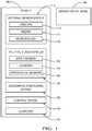
- FIG. 1is a functional block diagram illustrating an autonomous vehicle in accordance with an example embodiment.
- FIG. 2is a diagram of an autonomous vehicle travelling along a highway in accordance with aspects of the disclosure.
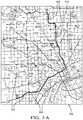
- FIG. 3 ais a diagram illustrating map data received by an autonomous vehicle from an external database.
- FIG. 3 bis an enlarged view of a portion of the map data illustrated in FIG. 3 a including map data sensed by the autonomous vehicle in accordance with aspects of the disclosure.
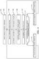
- FIG. 4is a flow chart of a first control method for an autonomous vehicle in accordance with aspects of the disclosure.
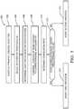
- FIG. 5is a flow chart of a second control method for an autonomous vehicle in accordance with aspects of the disclosure.
- FIG. 6 ais diagram of an autonomous vehicle travelling along a highway with a first traffic density in accordance with aspects of the disclosure.
- FIG. 6 bis diagram of an autonomous vehicle travelling along a highway with a second traffic density in accordance with aspects of the disclosure.
- FIG. 7is a top view of an autonomous vehicle in accordance with an example embodiment.
- FIG. 8is a diagram of an autonomous vehicle travelling along a road that has buildings and obstructions adjacent to the road.
- FIG. 1is a functional block diagram of a vehicle 100 in accordance with an example embodiment.
- Vehicle 100has an external sensor system 110 that includes cameras 112 , radar 114 , and microphone 116 .
- Vehicle 100also includes an internal sensor system 120 that includes speed sensor 122 , compass 124 and operational sensors 126 for measuring parameters such as engine temperature, tire pressure, oil pressure, battery charge, fuel level, and other operating conditions.
- Control systems 140are provided to regulate the operation of vehicle 100 regarding speed, braking, turning, lights, wipers, horn, and other functions.
- a geographic positioning system 150is provided that enables vehicle 100 to determine its geographic location.
- Vehicle 100communicates with a navigational database 160 maintained in a computer system outside the vehicle 100 to obtain information about road locations, road conditions, speed limits, road hazards, and traffic conditions.
- Computer 170 within vehicle 100receives data from geographic positioning system 150 and navigational database 160 to determine a turn-based routing strategy for driving the vehicle 100 from its current location to a selected destination.
- Computer 170receives data from external sensor system 110 and calculates the movements of the vehicle 100 needed to safely execute each step of the routing strategy.
- Vehicle 100can operate in a fully autonomous mode by giving instructions to control systems 140 or can operate in a semi-autonomous mode in which instructions are given to control systems 140 only in emergency situations. Vehicle 100 can also operate in an advisory mode in which vehicle 100 is under full control of a driver but provides recommendations and/or warnings to the driver relating to routing paths, potential hazards, and other items of interest.
- FIG. 2illustrates vehicle 100 driving along highway 200 including left lane 202 , center lane 204 , and right lane 206 .
- Other-vehicles 220 , 230 and 240are also travelling along highway 200 in the same direction of travel as vehicle 100 .
- Computer 170uses data from external sensor system 110 to detect the other-vehicles 220 , 230 and 240 , to determine their relative positions to vehicle 100 and to identify their blind spots 222 , 232 and 242 .
- Other-vehicle 220 and the vehicle 100are both in the left lane 202 and other-vehicle 220 is in front of vehicle 100 .
- Computer 170uses speed information from internal sensor system 120 to calculate a safe following distance 260 from other-vehicle 220 .
- the routing strategy calculated by computer 170requires vehicle 100 to exit the highway 200 at ramp 270 .
- computer 170calculates a travel path 280 for vehicle 100 to move from the left lane 202 to the right lane 206 while avoiding the other-vehicles 220 , 230 , and 240 and their respective blind spots 222 , 232 and 242 .
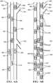
- FIG. 3 aillustrates map 300 received by computer 170 from navigational database 160 .
- Map 300includes the location and orientation of road network 310 .
- vehicle 100is travelling along route 320 calculated by computer 170 or, alternatively, calculated by a computer (not shown) external to vehicle 100 associated with the navigational database 160 .
- FIG. 3 billustrates an enlarged view of one portion of road network 310 and route 320 .
- Fundamental navigational prioritiessuch as direction of travel, target speed and lane selection are made with respect to data received from navigational database 160 .
- Current global positioning system (GPS) datahas a margin of error that does not allow for absolute accuracy of vehicle position and road location. Therefore, referring back to FIG.
- GPSglobal positioning system
- computer 170uses data from external sensor system 110 to detect instance of road features 330 such as lane lines 332 , navigational markers 334 , and pavement edges 336 to control the fine positioning of vehicle 100 .
- Computer 170calculates the GPS coordinates of detected instances of road features 330 , identifies corresponding map elements 340 , and compares the location of road features 330 and map elements 340 .
- FIG. 3 bis an enlarged view of a portion of map 300 from FIG. 3 a that shows a map region 350 in which there is a significant discrepancy between road features 330 and map elements 340 as might occur during a temporary detour. As discussed below, significant differences between the calculated position of road features 330 and map elements 340 will cause computer 170 to adjust a routing strategy for vehicle 100 .
- road features 330 and map elements 340can relate to characteristics about the road surface such as the surface material (dirt, gravel, concrete, asphalt). In another alternative embodiment, road features 330 and map elements 340 can relate to transient conditions that apply to an area of the road such as traffic congestion or weather conditions (rain, snow, high winds).
- FIG. 4illustrates an example flow chart 400 in accordance with some aspects of the disclosure discussed above.
- computer 170adopts a default control strategy for vehicle 100 .
- the default control strategyincludes a set of rules that will apply when there is a high degree of correlation between road features 330 and map elements 340 .
- the computer 170follows a routing path calculated based on the GPS location of vehicle 100 with respect to road network 310 on map 300 .
- Vehicle 100does not cross lane lines 332 or pavement edges 336 except during a lane change operation.
- Vehicle target speedis set based on speed limit information for road network 310 contained in navigational database 160 , except where user preferences have determined that the vehicle should travel a set interval above or below the speed limit.
- the minimum spacing between vehicle 100 to surrounding vehiclesis set to a standard interval.
- External sensor system 110operates in a standard mode in which the sensors scan in a standard pattern and at a standard refresh rate.
- computer 170selects a preferred road feature 330 (such as lane lines 332 ) and determines its respective location.
- computer 170determines the location of the selected instance of the road feature 330 and in block 408 compares this with the location of a corresponding map element 340 .
- computer 170determines a correlation rate between the location of road feature 330 and corresponding map element 340 .
- computer 170determines whether the correlation rate exceeds a predetermined value. If not, computer 170 adopts an alternative control strategy according to block 414 and reverts to block 404 to repeat the process described above. If the correlation rate is above the predetermined value, computer maintains the default control strategy according to block 416 and reverts to block 404 to repeat the process.
- the correlation ratecan be determined based on a wide variety of factors. For example, in reference to FIG. 3 b computer 170 can calculate the distance between road feature 330 and map element 340 at data points 370 , 372 , 374 , 376 , and 378 along map 300 . If the distance at each point exceeds a defined value, computer 170 will determine that the correlation rate is below the predetermined value. If this condition is reproduced over successive data points or over a significant number of data points along a defined interval, computer 170 will adopt the alternative control strategy. There may also be locations in which road features 330 are not detectable by the external sensor system 110 . For example, lane lines 332 may be faded or covered with snow. Pavement edges 334 may be also covered with snow or disguised by adjacent debris. Data points at which no correlation can be found between road features 330 and map elements 340 could also be treated as falling below the correlation rate even though a specific calculation cannot be made.
- only one of the road features 330are used to determine the correlation between road features 330 and map elements 340 .
- the correlation rateis determined based on multiple instances of the road features 330 such as lane lines 332 and pavement edges 336 .
- the individual correlation between one type of road feature 330 and map element 340is weighted differently than the correlation between other road features 330 and map elements 340 , such as pavement edges 334 , when determining an overall correlation rate. This would apply in situations where the favored road feature (in this case, lane lines 332 ) is deemed a more reliable tool for verification of the location of vehicle 100 relative to road network 310 .
- FIG. 5illustrates an example flow chart 500 for the alternative control strategy, which includes multiple protocols depending upon the situation determined by computer 170 .
- computer 170has adopted the alternative control strategy after following the process outlined in FIG. 4 .
- computer 170selects an alternative road feature 330 (such as pavement edges 336 ) and determines its respective location in block 506 .
- computer 170compares the location of the selected road feature 330 to a corresponding map element 340 and determines a correlation rate in block 510 .
- computer 170determines whether the correlation rate falls above a predetermined value. If so, computer 170 adopts a first protocol for alternative control strategy according to block 514 . If not, computer 170 adopts a second protocol for the alternative control strategy according to block 516 .
- computer 170relies on a secondary road feature 330 (such as pavement edges 336 ) for verification of the location of road network 310 relative to the vehicle 100 and for verification of the position of vehicle 100 within a lane on a roadway (such as the left lane 202 in highway 200 , as shown in FIG. 2 ).
- computer 170 in the first protocolmay continue to determine a correlation rate for the preferred road feature 330 selected according to the process outlined in FIG. 4 and, if the correlation rate exceeds a predetermined value, return to the default control strategy.
- the second protocolis triggered when the computer is unable to reliably use information about alternative road features 330 to verify the position of the vehicle 100 .
- computer 170may use the position and trajectory of surrounding vehicles to verify the location of road network 310 and to establish the position of vehicle 100 . If adjacent vehicles have a trajectory consistent with road network 310 on map 300 , computer will operate on the assumption that other vehicles are within designated lanes in a roadway. If traffic density is not sufficiently dense (or is non-existent) such that computer 170 cannot reliably use it for lane verification, computer 170 will rely solely on GPS location relative to the road network 310 for navigational control purposes.
- computer 170will rely on typical hazard avoidance protocols to deal with unexpected lane closures, accidents, road hazards, etc.
- Computer 170will also take directional cues from surrounding vehicles in situations where the detected road surface does not correlate with road network 310 but surrounding vehicles are following the detected road surface, or in situations where the path along road network 310 is blocked by a detected hazard but surrounding traffic is following a path off of the road network and off of the detected road surface.
- computer 170uses data from external sensor system 110 to detect road hazard 650 on highway 600 and to detect shoulder areas 660 and 662 along highway 200 .
- Computer 170also uses data from external sensor system 110 to detect hazard 670 in the shoulder area 660 along with structures 680 such as guard rails or bridge supports that interrupt shoulder areas 660 , 662 .
- Computer 170communicates with navigational database 160 regarding the location of hazards 650 , 670 detected by external sensor system 110 .
- Navigational database 160is simultaneously accessible by computer 170 and other computers in other vehicles and is updated with hazard-location information received by such computers to provide a real-time map of transient hazards.
- navigational database 160sends a request to computer 170 to validate the location of hazards 650 , 670 detected by another vehicle.
- Computer 170uses external sensor system 110 to detect the presence or absence of hazards 650 , 670 and sends a corresponding message to navigational database 160 .
- FIG. 6 aillustrates vehicle 100 driving along highway 600 including left lane 602 , center lane 604 , and right lane 606 .
- Surrounding vehicles 620are also travelling along highway 600 in the same direction of travel as vehicle 100 .
- Computer 170receives data from geographic positioning system 150 and navigational database 160 to determine a routing strategy for driving the vehicle 100 from its current location to a selected destination 610 .
- Computer 170determines a lane-selection strategy based on the number of lanes 602 , 604 , 606 on highway 600 , the distance to destination 610 , and the speed of vehicle 100 .
- the lane-selection strategygives a preference for the left lane 602 when vehicle 100 remains a significant distance from destination 610 .
- the lane-selection strategyalso disfavors the right lane in areas along highway 600 with significant entrance ramps 622 and exit ramps 624 .
- the lane selection strategydefines first zone 630 where vehicle 100 should begin to attempt a first lane change maneuver into center lane 604 , and a second zone 632 where vehicle should begin to attempt a second lane change maneuver into right lane 606 .
- computer 170directs vehicle 100 to make a lane change maneuver as soon as a safe path is available, which could include decreasing or increasing the speed of vehicle 100 to put it in a position where a safe path is available. If vehicle passes through a zone 630 , 632 without being able to successfully make a lane change maneuver, vehicle 100 will continue to attempt a lane change maneuver until it is no longer possible to reach destination 610 at which point the computer 170 will calculate a revised routing strategy for vehicle 100 .
- Computer 170adapts the lane selection strategy in real time based on information about surrounding vehicles 620 .
- Computer 170calculates a traffic density measurement based on the number and spacing of surrounding vehicles 620 in the vicinity of vehicle 100 .
- Computer 170also evaluates the number and complexity of potential lane change pathways in the vicinity of vehicle 100 to determine a freedom of movement factor for vehicle 100 .
- the freedom of movement factoror both, computer 170 evaluates whether to accelerate the lane change maneuver. For example, when traffic density is heavy and freedom of movement limited for vehicle 100 , as shown in FIG. 7 b , computer 170 may locate first and second zones 734 and 736 farther from destination 710 to give vehicle 100 more time to identify a safe path to maneuver. This is particularly useful when surrounding vehicles 620 are following each other at a distance that does not allow for a safe lane change between them.
- computer 170uses data from external sensor system 110 to detect the other-vehicles 220 , 230 , and 240 and to categorize them based on size and width into categories such as “car”, “passenger truck” and “semi-trailer truck.”
- other-vehicles 220 and 230are passenger cars and other-vehicle 240 is a semi-trailer truck, i.e. a large vehicle.
- computer 170also identifies hazard zones 250 that apply only to particular vehicle categories and only in particular circumstances. For example, in FIG.
- computer 170has identified the hazard zones 250 for other-vehicle 240 that represent areas where significant rain, standing water, and/or snow will be thrown from the tires of a typical semi-trailer truck. Based on information about weather and road conditions from navigational database 160 , road conditions detected by external sensor system 110 , or other sources, computer 170 determines whether the hazard zones 250 are active and should be avoided.
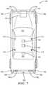
- FIG. 7illustrates a top view of vehicle 100 including radar sensors 710 and cameras 720 . Because a vehicle that is driven under autonomous control will likely have behavior patterns different from a driver-controlled vehicle, it is important to have a signal visible to other drivers that indicates when vehicle 100 is under autonomous control. This is especially valuable for nighttime driving when it may not be apparent that no one is in the driver's seat, or for situations in which a person is in the driver's seat but the vehicle 100 is under autonomous control. For that purpose, warning light 730 is provided and is placed in a location distinct from headlamps 740 , turn signals 750 , or brake lights 760 .
- warning light 730is of a color other than red, yellow, or white to further distinguish it from normal operating lights/signals 740 , 750 and 760 .
- warning lightcan comprise an embedded light emitting diode (LED) located within a laminated glass windshield 770 and/or laminated glass backlight 780 of vehicle 100 .
- LEDembedded light emitting diode
- One of the complexities of autonomous control of vehicle 100arises in negotiating the right-of-way between vehicles.
- Driver-controlled vehiclesoften perceive ambiguity when following the rules for determining which vehicle has the right of way. For example, at a four-way stop two vehicles may each perceive that they arrived at an intersection first. Or one vehicle may believe that all vehicles arrived at the same time but another vehicle perceived that one of the vehicles was actually the first to arrive.
- These situationsare often resolved by drivers giving a visual signal that they are yielding the right of way to another driver, such as with a hand wave. To handle this situation when vehicle 100 is under autonomous control, yield signal 790 is included on vehicle 100 .
- Yield signal 790can be a visual signal such as a light, an electronic signal (such as a radio-frequency signal) that can be detected by other vehicles, or a combination of both.
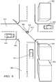
- FIG. 8illustrates vehicle 100 driving along road 800 .
- Road 810crosses road 800 at intersection 820 .
- Buildings 830are located along the sides of road 810 and 820 .
- Computer 170uses data from external sensor system 110 to detect approaching-vehicle 840 .
- external sensor system 110cannot detect hidden-vehicle 850 travelling along road 810 due to interference from one or more buildings 830 .
- Remote-sensor 860is mounted on a fixed structure 870 (such as a traffic signal 872 ) near intersection 820 and in a position that gives an unobstructed view along roads 800 and 810 .
- Computer 170uses data from remote-sensor 860 to determine the position and trajectory of hidden-vehicle 850 .
- This informationis used as needed by computer 170 to control the vehicle 100 and avoid a collision with hidden-vehicle 850 .
- computer 170will direct the vehicle 100 to proceed through intersection 820 .
- hidden-vehicle 850is approaching intersection 820 at a speed or trajectory inconsistent with a slowing or stopping behavior, computer 170 will direct vehicle to stop short of intersection 820 until it is determined that hidden-vehicle 850 will successfully stop at intersection 820 or has passed through intersection 820 .
Landscapes
- Engineering & Computer Science (AREA)
- Radar, Positioning & Navigation (AREA)
- Remote Sensing (AREA)
- Automation & Control Theory (AREA)
- Physics & Mathematics (AREA)
- General Physics & Mathematics (AREA)
- Aviation & Aerospace Engineering (AREA)
- Mechanical Engineering (AREA)
- Transportation (AREA)
- Optics & Photonics (AREA)
- Computer Vision & Pattern Recognition (AREA)
- Multimedia (AREA)
- Electromagnetism (AREA)
- Traffic Control Systems (AREA)
- Control Of Driving Devices And Active Controlling Of Vehicle (AREA)
Abstract
Description
Claims (18)
Priority Applications (1)
| Application Number | Priority Date | Filing Date | Title |
|---|---|---|---|
| US15/545,957US10678261B2 (en) | 2015-02-06 | 2015-12-07 | Method and apparatus for controlling an autonomous vehicle |
Applications Claiming Priority (3)
| Application Number | Priority Date | Filing Date | Title |
|---|---|---|---|
| US201562112775P | 2015-02-06 | 2015-02-06 | |
| US15/545,957US10678261B2 (en) | 2015-02-06 | 2015-12-07 | Method and apparatus for controlling an autonomous vehicle |
| PCT/US2015/064282WO2016126321A1 (en) | 2015-02-06 | 2015-12-07 | Method and apparatus for controlling an autonomous vehicle |
Related Parent Applications (1)
| Application Number | Title | Priority Date | Filing Date |
|---|---|---|---|
| PCT/US2015/064282A-371-Of-InternationalWO2016126321A1 (en) | 2015-02-06 | 2015-12-07 | Method and apparatus for controlling an autonomous vehicle |
Related Child Applications (1)
| Application Number | Title | Priority Date | Filing Date |
|---|---|---|---|
| US16/208,828DivisionUS10948924B2 (en) | 2015-02-06 | 2018-12-04 | Method and apparatus for controlling an autonomous vehicle |
Publications (2)
| Publication Number | Publication Date |
|---|---|
| US20180004223A1 US20180004223A1 (en) | 2018-01-04 |
| US10678261B2true US10678261B2 (en) | 2020-06-09 |
Family
ID=56564486
Family Applications (3)
| Application Number | Title | Priority Date | Filing Date |
|---|---|---|---|
| US15/545,957ActiveUS10678261B2 (en) | 2015-02-06 | 2015-12-07 | Method and apparatus for controlling an autonomous vehicle |
| US16/208,828Active2036-05-13US10948924B2 (en) | 2015-02-06 | 2018-12-04 | Method and apparatus for controlling an autonomous vehicle |
| US17/171,598Active2036-05-20US11543832B2 (en) | 2015-02-06 | 2021-02-09 | Method and apparatus for controlling an autonomous vehicle |
Family Applications After (2)
| Application Number | Title | Priority Date | Filing Date |
|---|---|---|---|
| US16/208,828Active2036-05-13US10948924B2 (en) | 2015-02-06 | 2018-12-04 | Method and apparatus for controlling an autonomous vehicle |
| US17/171,598Active2036-05-20US11543832B2 (en) | 2015-02-06 | 2021-02-09 | Method and apparatus for controlling an autonomous vehicle |
Country Status (2)
| Country | Link |
|---|---|
| US (3) | US10678261B2 (en) |
| WO (1) | WO2016126321A1 (en) |
Cited By (5)
| Publication number | Priority date | Publication date | Assignee | Title |
|---|---|---|---|---|
| US20190101929A1 (en)* | 2015-02-06 | 2019-04-04 | Aptiv Technologies Limited | Method and apparatus for controlling an autonomous vehicle |
| US10991247B2 (en) | 2015-02-06 | 2021-04-27 | Aptiv Technologies Limited | Method of automatically controlling an autonomous vehicle based on electronic messages from roadside infrastructure or other vehicles |
| US20240051529A1 (en)* | 2022-08-12 | 2024-02-15 | Honda Motor Co., Ltd. | Vehicle control device, vehicle control method, and storage medium |
| US20240203136A1 (en)* | 2022-12-19 | 2024-06-20 | Honda Motor Co., Ltd. | Vehicle control device, vehicle control method, and storage medium |
| US12371016B2 (en)* | 2022-08-12 | 2025-07-29 | Honda Motor Co., Ltd. | Vehicle control device, vehicle control method, and storage medium |
Families Citing this family (52)
| Publication number | Priority date | Publication date | Assignee | Title |
|---|---|---|---|---|
| US10599155B1 (en) | 2014-05-20 | 2020-03-24 | State Farm Mutual Automobile Insurance Company | Autonomous vehicle operation feature monitoring and evaluation of effectiveness |
| US9972054B1 (en) | 2014-05-20 | 2018-05-15 | State Farm Mutual Automobile Insurance Company | Accident fault determination for autonomous vehicles |
| US11669090B2 (en) | 2014-05-20 | 2023-06-06 | State Farm Mutual Automobile Insurance Company | Autonomous vehicle operation feature monitoring and evaluation of effectiveness |
| US20210133871A1 (en) | 2014-05-20 | 2021-05-06 | State Farm Mutual Automobile Insurance Company | Autonomous vehicle operation feature usage recommendations |
| US10373259B1 (en) | 2014-05-20 | 2019-08-06 | State Farm Mutual Automobile Insurance Company | Fully autonomous vehicle insurance pricing |
| US10387962B1 (en) | 2014-07-21 | 2019-08-20 | State Farm Mutual Automobile Insurance Company | Methods of reconstructing an accident scene using telematics data |
| US10157423B1 (en) | 2014-11-13 | 2018-12-18 | State Farm Mutual Automobile Insurance Company | Autonomous vehicle operating style and mode monitoring |
| US9805601B1 (en) | 2015-08-28 | 2017-10-31 | State Farm Mutual Automobile Insurance Company | Vehicular traffic alerts for avoidance of abnormal traffic conditions |
| JP2017114155A (en)* | 2015-12-21 | 2017-06-29 | 三菱自動車工業株式会社 | Drive support device |
| US11441916B1 (en) | 2016-01-22 | 2022-09-13 | State Farm Mutual Automobile Insurance Company | Autonomous vehicle trip routing |
| US10134278B1 (en) | 2016-01-22 | 2018-11-20 | State Farm Mutual Automobile Insurance Company | Autonomous vehicle application |
| US10493936B1 (en) | 2016-01-22 | 2019-12-03 | State Farm Mutual Automobile Insurance Company | Detecting and responding to autonomous vehicle collisions |
| US11242051B1 (en) | 2016-01-22 | 2022-02-08 | State Farm Mutual Automobile Insurance Company | Autonomous vehicle action communications |
| US11719545B2 (en) | 2016-01-22 | 2023-08-08 | Hyundai Motor Company | Autonomous vehicle component damage and salvage assessment |
| US20180164109A1 (en)* | 2016-07-29 | 2018-06-14 | Faraday&Future Inc. | Dynamic map pre-loading in vehicles |
| JP6583185B2 (en)* | 2016-08-10 | 2019-10-02 | トヨタ自動車株式会社 | Automatic driving system and automatic driving vehicle |
| DE102016222782A1 (en)* | 2016-11-18 | 2018-05-24 | Audi Ag | Autonomous control of a motor vehicle based on lane data; motor vehicle |
| US10186156B2 (en)* | 2017-05-25 | 2019-01-22 | Uber Technologies, Inc. | Deploying human-driven vehicles for autonomous vehicle routing and localization map updating |
| WO2018218146A1 (en)* | 2017-05-26 | 2018-11-29 | Google Llc | Data layers for a vehicle map service |
| US10663303B2 (en)* | 2017-06-12 | 2020-05-26 | Panasonic Intellectual Property Management Co., Ltd. | System and method for dynamically authenticating map data using blockchains |
| US11112796B2 (en)* | 2017-08-08 | 2021-09-07 | Uatc, Llc | Object motion prediction and autonomous vehicle control |
| US10872476B2 (en) | 2017-08-10 | 2020-12-22 | Amazon Technologies, Inc. | Broadcast strategy modes for autonomous vehicle operations |
| US10870437B2 (en) | 2017-08-10 | 2020-12-22 | Amazon Technologies, Inc. | Determination of strategy modes for autonomous vehicle operations |
| US11092961B2 (en) | 2017-08-10 | 2021-08-17 | Amazon Technologies, Inc. | Strategy modes for autonomous vehicle operations |
| US11079771B2 (en)* | 2017-08-10 | 2021-08-03 | Amazon Technologies, Inc. | Coordinated optimization of autonomous vehicle operations |
| US10509410B2 (en)* | 2017-12-06 | 2019-12-17 | Zoox, Inc. | External control of an autonomous vehicle |
| US10755111B2 (en) | 2018-01-29 | 2020-08-25 | Micron Technology, Inc. | Identifying suspicious entities using autonomous vehicles |
| US11009876B2 (en) | 2018-03-14 | 2021-05-18 | Micron Technology, Inc. | Systems and methods for evaluating and sharing autonomous vehicle driving style information with proximate vehicles |
| US11727794B2 (en) | 2018-03-14 | 2023-08-15 | Micron Technology, Inc. | Systems and methods for evaluating and sharing human driving style information with proximate vehicles |
| US10915159B2 (en)* | 2018-04-03 | 2021-02-09 | GM Global Technology Operations LLC | Method of controlling a vehicle to adjust perception system energy usage |
| US10997429B2 (en) | 2018-04-11 | 2021-05-04 | Micron Technology, Inc. | Determining autonomous vehicle status based on mapping of crowdsourced object data |
| US11480971B2 (en) | 2018-05-01 | 2022-10-25 | Honda Motor Co., Ltd. | Systems and methods for generating instructions for navigating intersections with autonomous vehicles |
| DE102018208593A1 (en)* | 2018-05-30 | 2019-12-05 | Continental Teves Ag & Co. Ohg | Method for checking whether a change of the driving mode can be made safely |
| US11161518B2 (en) | 2018-06-15 | 2021-11-02 | Micron Technology, Inc. | Detecting road conditions based on braking event data received from vehicles |
| US10909866B2 (en)* | 2018-07-20 | 2021-02-02 | Cybernet Systems Corp. | Autonomous transportation system and methods |
| US10915115B2 (en)* | 2018-08-02 | 2021-02-09 | Nvidia Corporation | Method and apparatus for enabling map updates using a blockchain platform |
| US10768637B2 (en)* | 2018-08-30 | 2020-09-08 | Pony Ai Inc. | Prioritizing vehicle navigation |
| EP3640665A1 (en) | 2018-10-16 | 2020-04-22 | Aptiv Technologies Limited | Method to improve the determination of a position of a roadside unit, roadside unit and system to provide position information |
| EP3654676B1 (en)* | 2018-11-16 | 2023-08-23 | Volkswagen Aktiengesellschaft | Method for data communication between at least two participants of a wireless communication system, corresponding control unit and vehicle equipped with a control unit as well as computer program |
| CN109747636A (en)* | 2019-01-15 | 2019-05-14 | 中国第一汽车股份有限公司 | Based on the curb position of long range ultrasonic wave and angle detecting method and its system |
| CN109814575B (en)* | 2019-02-22 | 2022-04-08 | 百度在线网络技术(北京)有限公司 | Lane changing route planning method and device for automatic driving vehicle and terminal |
| CN109949596A (en)* | 2019-02-28 | 2019-06-28 | 北京百度网讯科技有限公司 | Vehicle interaction method and apparatus for autonomous vehicles |
| CN109949612B (en)* | 2019-04-04 | 2020-06-30 | 哈尔滨工业大学 | Ghost probe accident early warning system based on information interaction |
| KR102715606B1 (en) | 2019-06-11 | 2024-10-11 | 주식회사 에이치엘클레무브 | Advanced Driver Assistance System, Vehicle having the same and method for controlling the vehicle |
| SE544208C2 (en)* | 2019-08-23 | 2022-03-01 | Scania Cv Ab | Method and control arrangement for vehicle motion planning and control algorithms |
| US11447134B2 (en) | 2019-09-18 | 2022-09-20 | Aptiv Technologies Limited | Vehicle route modification to improve vehicle location information |
| US11724696B2 (en)* | 2021-09-08 | 2023-08-15 | GM Global Technology Operations LLC | System and method of automatedly changing lanes for a vehicle |
| US12078738B2 (en) | 2021-11-09 | 2024-09-03 | Msrs Llc | Method, apparatus, and computer readable medium for a multi-source reckoning system |
| CN114802252A (en)* | 2022-05-07 | 2022-07-29 | 华人运通(上海)自动驾驶科技有限公司 | Control method and device for automatic lane changing of vehicle |
| US12332353B2 (en)* | 2022-08-16 | 2025-06-17 | Qualcomm Incorporated | Cellular radio frequency (RF) sensing in automobile navigation |
| EP4421772A1 (en)* | 2023-02-27 | 2024-08-28 | Continental Automotive Technologies GmbH | Method for calling the attention of a driver |
| US12259246B1 (en) | 2024-05-13 | 2025-03-25 | Msrs Llc | Method, apparatus, and computer readable medium for calculating a handrail influence intensity factor |
Citations (11)
| Publication number | Priority date | Publication date | Assignee | Title |
|---|---|---|---|---|
| US20100023183A1 (en)* | 2008-07-24 | 2010-01-28 | Gm Global Technology Operations, Inc. | Adaptive vehicle control system with integrated maneuver-based driving style recognition |
| US20100063720A1 (en)* | 2006-12-18 | 2010-03-11 | Hiroshi Machino | Navigation apparatus |
| US20130184926A1 (en)* | 2012-01-17 | 2013-07-18 | Ford Global Technologies, Llc | Autonomous lane control system |
| US8521352B1 (en)* | 2012-05-07 | 2013-08-27 | Google Inc. | Controlling a vehicle having inadequate map data |
| US20140081507A1 (en) | 2012-09-20 | 2014-03-20 | Google Inc. | Detecting road weather conditions |
| US20140210646A1 (en) | 2012-12-28 | 2014-07-31 | Balu Subramanya | Advanced parking and intersection management system |
| US20140297093A1 (en) | 2013-04-02 | 2014-10-02 | Panasonic Corporation | Autonomous vehicle and method of estimating self position of autonomous vehicle |
| US8935034B1 (en)* | 2012-04-13 | 2015-01-13 | Google Inc. | System and method for automatically detecting key behaviors by vehicles |
| US20160004915A1 (en)* | 2014-07-07 | 2016-01-07 | Here Global B.V. | Lane Level Traffic |
| US20160161267A1 (en)* | 2014-12-07 | 2016-06-09 | Toyota Motor Engineering & Manufacturing North America, Inc. | Driving action determination for travel route exit event |
| US9501058B1 (en) | 2013-03-12 | 2016-11-22 | Google Inc. | User interface for displaying object-based indications in an autonomous driving system |
Family Cites Families (118)
| Publication number | Priority date | Publication date | Assignee | Title |
|---|---|---|---|---|
| JP2856058B2 (en) | 1993-12-27 | 1999-02-10 | 住友電装株式会社 | Vehicle collision sensor |
| DE4410895B4 (en) | 1994-03-29 | 2004-11-25 | Robert Bosch Gmbh | Method and device for concealed installation of an ultrasonic sensor in an outer part of a motor vehicle |
| US7103460B1 (en) | 1994-05-09 | 2006-09-05 | Automotive Technologies International, Inc. | System and method for vehicle diagnostics |
| US7629899B2 (en) | 1997-10-22 | 2009-12-08 | Intelligent Technologies International, Inc. | Vehicular communication arrangement and method |
| US7426437B2 (en)* | 1997-10-22 | 2008-09-16 | Intelligent Technologies International, Inc. | Accident avoidance systems and methods |
| US7650210B2 (en) | 1995-06-07 | 2010-01-19 | Automotive Technologies International, Inc. | Remote vehicle diagnostic management |
| US6526352B1 (en) | 2001-07-19 | 2003-02-25 | Intelligent Technologies International, Inc. | Method and arrangement for mapping a road |
| US7075427B1 (en) | 1996-01-12 | 2006-07-11 | Eva Signal Corporation | Traffic warning system |
| US5995898A (en) | 1996-12-06 | 1999-11-30 | Micron Communication, Inc. | RFID system in communication with vehicle on-board computer |
| US6442473B1 (en) | 1999-01-28 | 2002-08-27 | International Business Machines Corporation | Method and apparatus for presenting traffic information in a vehicle |
| FR2791147B1 (en) | 1999-03-19 | 2002-08-30 | Saint Gobain Vitrage | ELECTROCHEMICAL DEVICE OF THE ELECTROCOMMANDABLE DEVICE TYPE WITH VARIABLE OPTICAL AND / OR ENERGY PROPERTIES |
| DE19947766A1 (en) | 1999-10-02 | 2001-05-10 | Bosch Gmbh Robert | Device for monitoring the surroundings of a parking vehicle |
| KR100338121B1 (en) | 2000-06-03 | 2002-05-24 | 하진규 | Apparatus collecting traffic information using laser |
| US6707391B1 (en) | 2000-09-27 | 2004-03-16 | Louis R. Monroe | Supplemental automotive traffic safety apparatus and method |
| WO2002091013A2 (en) | 2001-05-07 | 2002-11-14 | C3 Trans Systems Llc | Autonomous vehicle collision/crossing warning system and method |
| US6862537B2 (en) | 2002-03-21 | 2005-03-01 | Ford Global Technologies Llc | Sensor fusion system architecture |
| JP4088100B2 (en) | 2002-05-14 | 2008-05-21 | 株式会社村上開明堂 | Rearview mirror with built-in camera |
| US6864784B1 (en) | 2002-07-19 | 2005-03-08 | Barry Loeb | Vehicle speed and safety warning system |
| US8068036B2 (en) | 2002-07-22 | 2011-11-29 | Ohanes Ghazarian | Intersection vehicle collision avoidance system |
| US7725258B2 (en) | 2002-09-20 | 2010-05-25 | M7 Visual Intelligence, L.P. | Vehicle based data collection and processing system and imaging sensor system and methods thereof |
| US6810321B1 (en) | 2003-03-17 | 2004-10-26 | Sprint Communications Company L.P. | Vehicle traffic monitoring using cellular telephone location and velocity data |
| JP2004326705A (en) | 2003-04-28 | 2004-11-18 | Sony Corp | Vehicle communication apparatus and vehicle communication method |
| US20050187701A1 (en) | 2004-02-23 | 2005-08-25 | Baney Douglas M. | Traffic communication system |
| US20100013615A1 (en) | 2004-03-31 | 2010-01-21 | Carnegie Mellon University | Obstacle detection having enhanced classification |
| US7167104B2 (en) | 2004-06-16 | 2007-01-23 | M/A-Com, Inc. | System and method to wirelessly communicate information between traffic control signs and vehicles |
| EP1817784B1 (en) | 2004-12-03 | 2009-04-29 | Magna International Inc | Non-contact dead front actuation system |
| US7706978B2 (en) | 2005-09-02 | 2010-04-27 | Delphi Technologies, Inc. | Method for estimating unknown parameters for a vehicle object detection system |
| JP2007106199A (en) | 2005-10-12 | 2007-04-26 | Mitsuba Corp | Vehicle periphery monitor device |
| US7504957B2 (en) | 2006-01-10 | 2009-03-17 | Guardian Industries Corp. | Light sensor embedded on printed circuit board |
| US8050863B2 (en) | 2006-03-16 | 2011-11-01 | Gray & Company, Inc. | Navigation and control system for autonomous vehicles |
| WO2007143756A2 (en) | 2006-06-09 | 2007-12-13 | Carnegie Mellon University | System and method for autonomously convoying vehicles |
| JP2008003959A (en) | 2006-06-23 | 2008-01-10 | Omron Corp | Communication system for vehicle |
| JP4211809B2 (en) | 2006-06-30 | 2009-01-21 | トヨタ自動車株式会社 | Object detection device |
| US8532862B2 (en) | 2006-11-29 | 2013-09-10 | Ryan A. Neff | Driverless vehicle |
| US20120139754A1 (en) | 2009-08-11 | 2012-06-07 | Ginsberg Matthew L | Driver Safety Enhancement Using Intelligent Traffic Signals and GPS |
| US10083607B2 (en) | 2007-09-07 | 2018-09-25 | Green Driver, Inc. | Driver safety enhancement using intelligent traffic signals and GPS |
| US9852624B2 (en) | 2007-09-07 | 2017-12-26 | Connected Signals, Inc. | Network security system with application for driver safety system |
| EP2212160A4 (en) | 2007-11-26 | 2012-07-04 | Autoliv Dev | A system for classifying objects in the vicinity of a vehicle |
| US20090140887A1 (en) | 2007-11-29 | 2009-06-04 | Breed David S | Mapping Techniques Using Probe Vehicles |
| JP5066437B2 (en) | 2007-12-21 | 2012-11-07 | 富士重工業株式会社 | Vehicle travel control device |
| US8605947B2 (en) | 2008-04-24 | 2013-12-10 | GM Global Technology Operations LLC | Method for detecting a clear path of travel for a vehicle enhanced by object detection |
| US10107630B2 (en) | 2008-07-08 | 2018-10-23 | Nuriel Hatav | Driver alert system |
| DE102008049824B4 (en) | 2008-10-01 | 2014-09-04 | Universität Kassel | Method for collision avoidance |
| US8604968B2 (en) | 2008-10-08 | 2013-12-10 | Delphi Technologies, Inc. | Integrated radar-camera sensor |
| US8126642B2 (en) | 2008-10-24 | 2012-02-28 | Gray & Company, Inc. | Control and systems for autonomously driven vehicles |
| KR100996284B1 (en) | 2008-12-15 | 2010-11-23 | 조선대학교산학협력단 | Inter-vehicle information transmission system |
| US20100238006A1 (en) | 2009-03-17 | 2010-09-23 | Ford Global Technologies, Llc | Concealed display for an external surface of a vehicle |
| WO2010124158A1 (en) | 2009-04-24 | 2010-10-28 | 3M Innovative Properties Company | Light assembly |
| US8340852B2 (en) | 2009-04-29 | 2012-12-25 | Honeywell International Inc. | System and method for simultaneous localization and map building |
| JP5351602B2 (en) | 2009-05-11 | 2013-11-27 | 本田技研工業株式会社 | Bumper structure |
| US8199028B2 (en) | 2009-07-16 | 2012-06-12 | GM Global Technology Operations LLC | Protocol for map data transmission for infrastructure to vehicle communications |
| KR20110023952A (en) | 2009-09-01 | 2011-03-09 | (주)차바이오앤디오스텍 | Driving Information Providing System of Proximity Vehicle and Its Provision Method |
| DE102009048493A1 (en) | 2009-09-25 | 2011-04-07 | Valeo Schalter Und Sensoren Gmbh | A driver assistance system for a vehicle, vehicle with a driver assistance system, and method for assisting a driver in driving a vehicle |
| US20110161987A1 (en)* | 2009-12-30 | 2011-06-30 | Anqi Andrew Huang | Scaling notifications of events in a social networking system |
| US8600606B2 (en) | 2010-02-11 | 2013-12-03 | GM Global Technology Operations LLC | Vehicle safety systems and methods |
| EP2559597B1 (en) | 2010-04-13 | 2014-05-07 | Toyota Jidosha Kabushiki Kaisha | Pedestrian collision detection device |
| US9069059B2 (en) | 2010-05-13 | 2015-06-30 | Laser Lions LLC | Concealed light detection and ranging system |
| US20120022776A1 (en) | 2010-06-07 | 2012-01-26 | Javad Razavilar | Method and Apparatus for Advanced Intelligent Transportation Systems |
| US20120041632A1 (en) | 2010-08-12 | 2012-02-16 | Robert Bosch Gmbh | Combined lane change assist and rear, cross-traffic alert functionality |
| DE102010034140A1 (en) | 2010-08-12 | 2012-02-16 | Valeo Schalter Und Sensoren Gmbh | Method for displaying images on a display device and driver assistance system |
| US8504275B2 (en) | 2010-09-30 | 2013-08-06 | Robert Bosch Gmbh | Adaptive cruise control acceleration rate control |
| US8509982B2 (en) | 2010-10-05 | 2013-08-13 | Google Inc. | Zone driving |
| KR20120072020A (en) | 2010-12-23 | 2012-07-03 | 한국전자통신연구원 | Method and apparatus for detecting run and road information of autonomous driving system |
| DE102011000501B4 (en) | 2011-02-04 | 2022-03-24 | Dr. Ing. H.C. F. Porsche Aktiengesellschaft | Screen for a sensor unit of a motor vehicle |
| US9035797B2 (en) | 2011-03-09 | 2015-05-19 | Maya Varma | Intelligent traffic alerting and control system |
| KR101071914B1 (en) | 2011-03-16 | 2011-10-11 | 강재민 | Automobile crash notification system and method |
| WO2012129425A2 (en) | 2011-03-23 | 2012-09-27 | Tk Holdings Inc. | Driver assistance system |
| JP5765995B2 (en) | 2011-03-31 | 2015-08-19 | 富士通テン株式会社 | Image display system |
| JP5333509B2 (en) | 2011-04-27 | 2013-11-06 | 株式会社デンソー | Follow-up vehicle follower |
| US8589014B2 (en) | 2011-06-01 | 2013-11-19 | Google Inc. | Sensor field selection |
| US8195394B1 (en) | 2011-07-13 | 2012-06-05 | Google Inc. | Object detection and classification for autonomous vehicles |
| US8775006B2 (en) | 2011-07-14 | 2014-07-08 | GM Global Technology Operations LLC | System and method for enhanced vehicle control |
| CN103635356B (en) | 2011-08-08 | 2016-07-06 | 布施真空株式会社 | Vehicle functional component |
| KR101877708B1 (en) | 2011-09-06 | 2018-07-13 | 현대모비스 주식회사 | Apparatus for controlling smart cruise and method thereof |
| US20130271292A1 (en) | 2011-10-09 | 2013-10-17 | James Andrew McDermott | Driver Alert and Monitoring System |
| US8694222B2 (en) | 2011-10-26 | 2014-04-08 | GM Global Technology Operations LLC | Collision avoidance system and method of operating the same |
| US8612135B1 (en) | 2012-02-14 | 2013-12-17 | Google Inc. | Method and apparatus to localize an autonomous vehicle using convolution |
| US8694224B2 (en) | 2012-03-01 | 2014-04-08 | Magna Electronics Inc. | Vehicle yaw rate correction |
| DE102012101781B4 (en) | 2012-03-02 | 2014-07-10 | Continental Automotive Gmbh | Support frame for sensor devices in vehicles |
| US8825265B1 (en) | 2012-03-16 | 2014-09-02 | Google Inc. | Approach for consolidating observed vehicle trajectories into a single representative trajectory |
| US8880272B1 (en) | 2012-03-16 | 2014-11-04 | Google Inc. | Approach for estimating the geometry of roads and lanes by using vehicle trajectories |
| US8718861B1 (en) | 2012-04-11 | 2014-05-06 | Google Inc. | Determining when to drive autonomously |
| US8781669B1 (en) | 2012-05-14 | 2014-07-15 | Google Inc. | Consideration of risks in active sensing for an autonomous vehicle |
| US20130321627A1 (en) | 2012-05-31 | 2013-12-05 | John C. Turn, JR. | Road departure sensing and intelligent driving systems and methods |
| US9600556B2 (en) | 2012-06-19 | 2017-03-21 | Sikorsky Aircraft Corporation | Method for three dimensional perception processing and classification |
| US9180882B1 (en) | 2012-06-20 | 2015-11-10 | Google Inc. | Avoiding blind spots of other vehicles |
| DE102012106691B4 (en) | 2012-07-24 | 2024-07-11 | Valeo Schalter Und Sensoren Gmbh | Alternative installation of a concealed ultrasonic sensor in the vehicle |
| US9187091B2 (en) | 2012-07-30 | 2015-11-17 | Ford Global Technologies, Llc | Collision detection system with a plausibiity module |
| US9110196B2 (en) | 2012-09-20 | 2015-08-18 | Google, Inc. | Detecting road weather conditions |
| JP6118570B2 (en) | 2013-02-01 | 2017-04-19 | 株式会社ブリヂストン | Raw tire support device and method for removing drum from raw tire |
| JP6158523B2 (en) | 2013-02-04 | 2017-07-05 | トヨタ自動車株式会社 | Inter-vehicle distance control device |
| US8855849B1 (en) | 2013-02-25 | 2014-10-07 | Google Inc. | Object detection based on known structures of an environment of an autonomous vehicle |
| US8849494B1 (en) | 2013-03-15 | 2014-09-30 | Google Inc. | Data selection by an autonomous vehicle for trajectory modification |
| US9254846B2 (en) | 2013-05-03 | 2016-02-09 | Google Inc. | Predictive reasoning for controlling speed of a vehicle |
| US8825259B1 (en) | 2013-06-21 | 2014-09-02 | Google Inc. | Detecting lane closures and lane shifts by an autonomous vehicle |
| US10551851B2 (en) | 2013-07-01 | 2020-02-04 | Steven Sounyoung Yu | Autonomous unmanned road vehicle for making deliveries |
| DE202013006196U1 (en) | 2013-07-09 | 2014-10-13 | GM Global Technology Operations LLC (n. d. Gesetzen des Staates Delaware) | Driver assistance system for a motor vehicle and motor vehicle |
| US8818681B1 (en) | 2013-07-24 | 2014-08-26 | Google Inc. | Detecting and responding to tailgaters |
| US20150100189A1 (en) | 2013-10-07 | 2015-04-09 | Ford Global Technologies, Llc | Vehicle-to-infrastructure communication |
| US9881220B2 (en) | 2013-10-25 | 2018-01-30 | Magna Electronics Inc. | Vehicle vision system utilizing communication system |
| US9142127B1 (en) | 2014-04-29 | 2015-09-22 | Maxwell Consulting, LLC | Systems and methods for traffic guidance nodes and traffic navigating entities |
| US9707960B2 (en) | 2014-07-31 | 2017-07-18 | Waymo Llc | Traffic signal response for autonomous vehicles |
| US20160231746A1 (en) | 2015-02-06 | 2016-08-11 | Delphi Technologies, Inc. | System And Method To Operate An Automated Vehicle |
| WO2016126323A1 (en) | 2015-02-06 | 2016-08-11 | Delphi Technologies, Inc. | Adaptive cruise control integrated with lane keeping assist system |
| WO2016126317A1 (en) | 2015-02-06 | 2016-08-11 | Delphi Technologies, Inc. | Method of automatically controlling an autonomous vehicle based on electronic messages from roadside infrastructure of other vehicles |
| WO2016126322A1 (en) | 2015-02-06 | 2016-08-11 | Delphi Technologies, Inc. | Autonomous vehicle with unobtrusive sensors |
| WO2016126315A1 (en) | 2015-02-06 | 2016-08-11 | Delphi Technologies, Inc. | Autonomous guidance system |
| WO2016126318A1 (en) | 2015-02-06 | 2016-08-11 | Delphi Technologies, Inc. | Method of automatically controlling an autonomous vehicle based on cellular telephone location information |
| WO2016126319A1 (en) | 2015-02-06 | 2016-08-11 | Delphi Technologies, Inc. | Pulsed led vehicle to vehicle communication system |
| WO2016126316A1 (en) | 2015-02-06 | 2016-08-11 | Delphi Technologies, Inc. | Autonomous guidance system |
| US10678261B2 (en) | 2015-02-06 | 2020-06-09 | Aptiv Technologies Limited | Method and apparatus for controlling an autonomous vehicle |
| US10144424B2 (en) | 2015-04-09 | 2018-12-04 | Toyota Jidosha Kabushiki Kaisha | Arrangement structure for vicinity information detection sensor |
| US10035509B2 (en) | 2015-08-06 | 2018-07-31 | Safer Technology Solutions LLC | Early warning intersection device |
| JP7055743B2 (en) | 2016-08-08 | 2022-04-18 | 株式会社小糸製作所 | Vehicle monitoring system using multiple cameras |
| JP6786302B2 (en) | 2016-08-12 | 2020-11-18 | 株式会社小糸製作所 | Lighting device |
| US10514303B2 (en) | 2017-06-29 | 2019-12-24 | Ford Global Technologies, Llc | Sensor pod with breathable cabin interface |
| CN111108409A (en) | 2017-09-20 | 2020-05-05 | 株式会社小糸制作所 | Vehicle exterior panel with sensor |
| US10668793B2 (en) | 2018-01-05 | 2020-06-02 | Toyota Motor Engineering & Manufacturing North America, Inc. | Retractable autonomous roof panel |
- 2015
- 2015-12-07USUS15/545,957patent/US10678261B2/enactiveActive
- 2015-12-07WOPCT/US2015/064282patent/WO2016126321A1/ennot_activeCeased
- 2018
- 2018-12-04USUS16/208,828patent/US10948924B2/enactiveActive
- 2021
- 2021-02-09USUS17/171,598patent/US11543832B2/enactiveActive
Patent Citations (12)
| Publication number | Priority date | Publication date | Assignee | Title |
|---|---|---|---|---|
| US20100063720A1 (en)* | 2006-12-18 | 2010-03-11 | Hiroshi Machino | Navigation apparatus |
| US20100023183A1 (en)* | 2008-07-24 | 2010-01-28 | Gm Global Technology Operations, Inc. | Adaptive vehicle control system with integrated maneuver-based driving style recognition |
| US20130184926A1 (en)* | 2012-01-17 | 2013-07-18 | Ford Global Technologies, Llc | Autonomous lane control system |
| US8935034B1 (en)* | 2012-04-13 | 2015-01-13 | Google Inc. | System and method for automatically detecting key behaviors by vehicles |
| US8521352B1 (en)* | 2012-05-07 | 2013-08-27 | Google Inc. | Controlling a vehicle having inadequate map data |
| US20140081507A1 (en) | 2012-09-20 | 2014-03-20 | Google Inc. | Detecting road weather conditions |
| US20140210646A1 (en) | 2012-12-28 | 2014-07-31 | Balu Subramanya | Advanced parking and intersection management system |
| US9501058B1 (en) | 2013-03-12 | 2016-11-22 | Google Inc. | User interface for displaying object-based indications in an autonomous driving system |
| US20140297093A1 (en) | 2013-04-02 | 2014-10-02 | Panasonic Corporation | Autonomous vehicle and method of estimating self position of autonomous vehicle |
| US20160004915A1 (en)* | 2014-07-07 | 2016-01-07 | Here Global B.V. | Lane Level Traffic |
| US20160161267A1 (en)* | 2014-12-07 | 2016-06-09 | Toyota Motor Engineering & Manufacturing North America, Inc. | Driving action determination for travel route exit event |
| US9429440B2 (en) | 2014-12-07 | 2016-08-30 | Toyota Motor Engineering & Manufacturing North America, Inc. | Driving action determination for travel route exit event |
Cited By (8)
| Publication number | Priority date | Publication date | Assignee | Title |
|---|---|---|---|---|
| US20190101929A1 (en)* | 2015-02-06 | 2019-04-04 | Aptiv Technologies Limited | Method and apparatus for controlling an autonomous vehicle |
| US10948924B2 (en)* | 2015-02-06 | 2021-03-16 | Aptiv Technologies Limited | Method and apparatus for controlling an autonomous vehicle |
| US10991247B2 (en) | 2015-02-06 | 2021-04-27 | Aptiv Technologies Limited | Method of automatically controlling an autonomous vehicle based on electronic messages from roadside infrastructure or other vehicles |
| US11543832B2 (en) | 2015-02-06 | 2023-01-03 | Aptiv Technologies Limited | Method and apparatus for controlling an autonomous vehicle |
| US11763670B2 (en) | 2015-02-06 | 2023-09-19 | Aptiv Technologies Limited | Method of automatically controlling an autonomous vehicle based on electronic messages from roadside infrastructure or other vehicles |
| US20240051529A1 (en)* | 2022-08-12 | 2024-02-15 | Honda Motor Co., Ltd. | Vehicle control device, vehicle control method, and storage medium |
| US12371016B2 (en)* | 2022-08-12 | 2025-07-29 | Honda Motor Co., Ltd. | Vehicle control device, vehicle control method, and storage medium |
| US20240203136A1 (en)* | 2022-12-19 | 2024-06-20 | Honda Motor Co., Ltd. | Vehicle control device, vehicle control method, and storage medium |
Also Published As
| Publication number | Publication date |
|---|---|
| US10948924B2 (en) | 2021-03-16 |
| WO2016126321A1 (en) | 2016-08-11 |
| US20190101929A1 (en) | 2019-04-04 |
| US20210165420A1 (en) | 2021-06-03 |
| US20180004223A1 (en) | 2018-01-04 |
| US11543832B2 (en) | 2023-01-03 |
Similar Documents
| Publication | Publication Date | Title |
|---|---|---|
| US11543832B2 (en) | Method and apparatus for controlling an autonomous vehicle | |
| US11550331B1 (en) | Detecting street parked vehicles | |
| US20200341487A1 (en) | System and Method to Operate an Automated Vehicle | |
| US20230227067A1 (en) | System and method for situational behavior of an autonomous vehicle | |
| EP3880529B1 (en) | Vehicle control system and method | |
| JP7063310B2 (en) | Map generation system, in-vehicle device | |
| US10239539B2 (en) | Vehicle travel control method and vehicle travel control device | |
| CN108604419B (en) | Vehicle travel control method and vehicle travel control device | |
| KR20230124662A (en) | Systems and methods for terrain-based insights for advanced driver assistance systems | |
| US20090326796A1 (en) | Method and system to estimate driving risk based on a heirarchical index of driving | |
| CN111415522A (en) | Method for planning a vehicle trajectory | |
| US20190333373A1 (en) | Vehicle Behavior Prediction Method and Vehicle Behavior Prediction Apparatus | |
| US20200242939A1 (en) | Vehicle control device | |
| US11703347B2 (en) | Method for producing an autonomous navigation map for a vehicle | |
| RU2660425C1 (en) | Device for calculating route of motion | |
| JP5531733B2 (en) | Road information acquisition device | |
| CN109425861A (en) | This truck position confidence level arithmetic unit | |
| JP2020125108A (en) | Lane detection method and system for vehicle | |
| GB2579022A (en) | Vehicle control system and method | |
| KR20190064228A (en) | Apparatus and method of providing information of traffic lanes using image sensing and vehicle control method using the same | |
| JP2022114191A (en) | Vehicle travel control device | |
| US11685404B2 (en) | Autonomous driving control method and autonomous driving control system | |
| GB2578915A (en) | Vehicle control system and method | |
| WO2020045344A1 (en) | Map generation system and in-vehicle device | |
| CN114729815B (en) | Method for approving the distance travelled |
Legal Events
| Date | Code | Title | Description |
|---|---|---|---|
| AS | Assignment | Owner name:DELPHI TECHNOLOGIES, INC., MICHIGAN Free format text:ASSIGNMENT OF ASSIGNORS INTEREST;ASSIGNOR:BALDWIN, CRAIG A.;REEL/FRAME:043082/0686 Effective date:20170719 | |
| AS | Assignment | Owner name:APTIV TECHNOLOGIES LIMITED, BARBADOS Free format text:ASSIGNMENT OF ASSIGNORS INTEREST;ASSIGNOR:DELPHI TECHNOLOGIES INC.;REEL/FRAME:047153/0902 Effective date:20180101 | |
| STPP | Information on status: patent application and granting procedure in general | Free format text:RESPONSE TO NON-FINAL OFFICE ACTION ENTERED AND FORWARDED TO EXAMINER | |
| STPP | Information on status: patent application and granting procedure in general | Free format text:FINAL REJECTION MAILED | |
| STPP | Information on status: patent application and granting procedure in general | Free format text:ADVISORY ACTION MAILED | |
| STPP | Information on status: patent application and granting procedure in general | Free format text:DOCKETED NEW CASE - READY FOR EXAMINATION | |
| STPP | Information on status: patent application and granting procedure in general | Free format text:NON FINAL ACTION MAILED | |
| STPP | Information on status: patent application and granting procedure in general | Free format text:RESPONSE TO NON-FINAL OFFICE ACTION ENTERED AND FORWARDED TO EXAMINER | |
| STCF | Information on status: patent grant | Free format text:PATENTED CASE | |
| MAFP | Maintenance fee payment | Free format text:PAYMENT OF MAINTENANCE FEE, 4TH YEAR, LARGE ENTITY (ORIGINAL EVENT CODE: M1551); ENTITY STATUS OF PATENT OWNER: LARGE ENTITY Year of fee payment:4 | |
| AS | Assignment | Owner name:APTIV TECHNOLOGIES (2) S.A R.L., LUXEMBOURG Free format text:ENTITY CONVERSION;ASSIGNOR:APTIV TECHNOLOGIES LIMITED;REEL/FRAME:066746/0001 Effective date:20230818 Owner name:APTIV MANUFACTURING MANAGEMENT SERVICES S.A R.L., LUXEMBOURG Free format text:MERGER;ASSIGNOR:APTIV TECHNOLOGIES (2) S.A R.L.;REEL/FRAME:066566/0173 Effective date:20231005 Owner name:APTIV TECHNOLOGIES AG, SWITZERLAND Free format text:ASSIGNMENT OF ASSIGNORS INTEREST;ASSIGNOR:APTIV MANUFACTURING MANAGEMENT SERVICES S.A R.L.;REEL/FRAME:066551/0219 Effective date:20231006 |