US10678240B2 - Sensor modification based on an annotated environmental model - Google Patents
Sensor modification based on an annotated environmental modelDownload PDFInfo
- Publication number
- US10678240B2 US10678240B2US15/260,149US201615260149AUS10678240B2US 10678240 B2US10678240 B2US 10678240B2US 201615260149 AUS201615260149 AUS 201615260149AUS 10678240 B2US10678240 B2US 10678240B2
- Authority
- US
- United States
- Prior art keywords
- vehicle
- environmental model
- sensor
- classification result
- data
- Prior art date
- Legal status (The legal status is an assumption and is not a legal conclusion. Google has not performed a legal analysis and makes no representation as to the accuracy of the status listed.)
- Active, expires
Links
Images


Classifications
- G—PHYSICS
- G05—CONTROLLING; REGULATING
- G05D—SYSTEMS FOR CONTROLLING OR REGULATING NON-ELECTRIC VARIABLES
- G05D1/00—Control of position, course, altitude or attitude of land, water, air or space vehicles, e.g. using automatic pilots
- G05D1/0088—Control of position, course, altitude or attitude of land, water, air or space vehicles, e.g. using automatic pilots characterized by the autonomous decision making process, e.g. artificial intelligence, predefined behaviours
- B—PERFORMING OPERATIONS; TRANSPORTING
- B60—VEHICLES IN GENERAL
- B60W—CONJOINT CONTROL OF VEHICLE SUB-UNITS OF DIFFERENT TYPE OR DIFFERENT FUNCTION; CONTROL SYSTEMS SPECIALLY ADAPTED FOR HYBRID VEHICLES; ROAD VEHICLE DRIVE CONTROL SYSTEMS FOR PURPOSES NOT RELATED TO THE CONTROL OF A PARTICULAR SUB-UNIT
- B60W40/00—Estimation or calculation of non-directly measurable driving parameters for road vehicle drive control systems not related to the control of a particular sub unit, e.g. by using mathematical models
- B60W40/02—Estimation or calculation of non-directly measurable driving parameters for road vehicle drive control systems not related to the control of a particular sub unit, e.g. by using mathematical models related to ambient conditions
- G06K9/00791—
- G—PHYSICS
- G06—COMPUTING OR CALCULATING; COUNTING
- G06N—COMPUTING ARRANGEMENTS BASED ON SPECIFIC COMPUTATIONAL MODELS
- G06N20/00—Machine learning
- G06N7/005—
- G—PHYSICS
- G06—COMPUTING OR CALCULATING; COUNTING
- G06N—COMPUTING ARRANGEMENTS BASED ON SPECIFIC COMPUTATIONAL MODELS
- G06N7/00—Computing arrangements based on specific mathematical models
- G06N7/01—Probabilistic graphical models, e.g. probabilistic networks
- G—PHYSICS
- G06—COMPUTING OR CALCULATING; COUNTING
- G06V—IMAGE OR VIDEO RECOGNITION OR UNDERSTANDING
- G06V20/00—Scenes; Scene-specific elements
- G06V20/50—Context or environment of the image
- G06V20/56—Context or environment of the image exterior to a vehicle by using sensors mounted on the vehicle
- H—ELECTRICITY
- H04—ELECTRIC COMMUNICATION TECHNIQUE
- H04W—WIRELESS COMMUNICATION NETWORKS
- H04W4/00—Services specially adapted for wireless communication networks; Facilities therefor
- H04W4/70—Services for machine-to-machine communication [M2M] or machine type communication [MTC]
- B—PERFORMING OPERATIONS; TRANSPORTING
- B60—VEHICLES IN GENERAL
- B60W—CONJOINT CONTROL OF VEHICLE SUB-UNITS OF DIFFERENT TYPE OR DIFFERENT FUNCTION; CONTROL SYSTEMS SPECIALLY ADAPTED FOR HYBRID VEHICLES; ROAD VEHICLE DRIVE CONTROL SYSTEMS FOR PURPOSES NOT RELATED TO THE CONTROL OF A PARTICULAR SUB-UNIT
- B60W2510/00—Input parameters relating to a particular sub-units
- B60W2510/18—Braking system
- B—PERFORMING OPERATIONS; TRANSPORTING
- B60—VEHICLES IN GENERAL
- B60W—CONJOINT CONTROL OF VEHICLE SUB-UNITS OF DIFFERENT TYPE OR DIFFERENT FUNCTION; CONTROL SYSTEMS SPECIALLY ADAPTED FOR HYBRID VEHICLES; ROAD VEHICLE DRIVE CONTROL SYSTEMS FOR PURPOSES NOT RELATED TO THE CONTROL OF A PARTICULAR SUB-UNIT
- B60W2510/00—Input parameters relating to a particular sub-units
- B60W2510/20—Steering systems
Definitions
- This disclosureis generally related to automated driving and assistance systems and, more specifically, to determining situational awareness in automated driving and assistance systems.
- ADASadvanced driver assistance systems
- ADautonomous driving
- Certain ADAS and AD systemsperform driving operations based on a situational awareness of the vehicle's surroundings and the state of the vehicle.
- the situational awareness of the vehiclecan include a classification, such as a situational annotation, of the current driving situation in which the vehicle is operating.
- Machine learning techniquesare one of the possibilities used to classify a situation and generate a situational annotation.
- a situationis classified based on data from a single source of data (such as a single sensor modality) and/or object-level data from multiple sensors. Classifying a situation using these and other existing approaches, however, can be computationally inefficient and inaccurate.
- a computing systemreceives an annotated environmental model for a vehicle.
- the annotated environmental modelcan include data from a plurality of modalities.
- the computing systemuses a classifier to determine an annotation of the vehicle situation based, at least in part, on the annotated environmental model.
- the computing systemprovides the situational annotation to a driving functionality system.
- the driving functionality systemis configured to use the situational annotation to generate signals to control operation the vehicle.
- FIG. 1illustrates an example autonomous driving system according to various embodiments.
- FIG. 2Aillustrates example measurement coordinate fields for a sensor system deployed in a vehicle according to various embodiments.
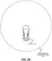
- FIG. 2Billustrates an example environmental coordinate field associated with an environmental model for a vehicle according to various embodiments.
- FIG. 3illustrates an example sensor fusion system according to various examples.
- FIG. 4illustrates an example flowchart for populating and annotating an environmental model according to various examples.
- FIG. 5illustrates an example flowchart for determining a situational annotation of a vehicle according to various examples.
- FIG. 6illustrates an example block diagram for determining a situational annotation of a vehicle according to various examples.
- FIG. 7illustrates an example flowchart for adjusting a region of interest according to various examples.
- FIG. 8illustrates an example flowchart for updating a situational awareness classifier according to various examples.
- FIGS. 9 and 10illustrate an example of a computer system of the type that may be used to implement various embodiments.
- FIG. 1illustrates an example autonomous driving system 100 according to various embodiments.
- the autonomous driving system 100when installed in a vehicle, can sense an environment surrounding the vehicle and control operation of the vehicle based, at least in part, on the sensed environment.
- the autonomous driving system 100can classify its surroundings to determine a situational annotation, classification, and/or awareness of the vehicle and its surroundings.
- the situational annotationcan be used to evaluate driving situations and allow various advanced driver assistance systems (ADAS) and autonomous driving (AD) systems to perform situation aware driving operations.
- ADASadvanced driver assistance systems
- ADautonomous driving
- the autonomous driving system 100can include a sensor system 110 having multiple sensors, each of which can measure different portions of the environment surrounding the vehicle and output the measurements as raw measurement data 115 .
- the raw measurement data 115can include characteristics of light, electromagnetic waves, or sound captured by the sensors, such as an intensity or a frequency of the light, electromagnetic waves, or the sound, an angle of reception by the sensors, a time delay between a transmission and the corresponding reception of the light, electromagnetic waves, or the sound, a time of capture of the light, electromagnetic waves, or sound, or the like.
- the sensor system 110can include multiple different types of sensors, such as image capture devices 111 , Radio Detection and Ranging (Radar) devices 112 , Light Detection and Ranging (Lidar) devices 113 , ultra-sonic devices 114 , microphones, infrared or night-vision cameras, time-of-flight cameras, cameras capable of detecting and transmitting differences in pixel intensity, or the like.
- An image capture device 111such as one or more cameras, can capture at least one image of at least a portion of the environment surrounding the vehicle.
- the image capture device 111can output the captured image(s) as raw measurement data 115 , which, in some embodiments, can be unprocessed and/or uncompressed pixel data corresponding to the captured image(s).
- a radar device 112can emit radio signals into the environment surrounding the vehicle. Since the emitted radio signals may reflect off of objects in the environment, the radar device 112 can detect the reflected radio signals incoming from the environment. The radar device 112 can measure the incoming radio signals by, for example, measuring a signal strength of the radio signals, a reception angle, a frequency, or the like. The radar device 112 also can measure a time delay between an emission of a radio signal and a measurement of the incoming radio signals from the environment that corresponds to emitted radio signals reflected off of objects in the environment. The radar device 112 can output the measurements of the incoming radio signals as the raw measurement data 115 .
- a lidar device 113can transmit light, such as from a laser or other optical transmission device, into the environment surrounding the vehicle.
- the transmitted lightin some embodiments, can be pulses of ultraviolet light, visible light, near infrared light, or the like. Since the transmitted light can reflect off of objects in the environment, the lidar device 113 can include a photo detector to measure light incoming from the environment.
- the lidar device 113can measure the incoming light by, for example, measuring an intensity of the light, a wavelength, or the like.
- the lidar device 113also can measure a time delay between a transmission of a light pulse and a measurement of the light incoming from the environment that corresponds to transmitted light having reflected off of objects in the environment.
- the lidar device 113can output the measurements of the incoming light and the time delay as the raw measurement data 115 .
- An ultrasonic device 114can emit acoustic pulses, for example, generated by transducers or the like, into the environment surrounding the vehicle.
- the ultra-sonic device 114can detect ultra-sonic sound incoming from the environment, such as for example, the emitted acoustic pulses having been reflected off of objects in the environment.
- the ultra-sonic device 114also can measure a time delay between emission of the acoustic pulses and reception of the ultra-sonic sound from the environment that corresponds to the emitted acoustic pulses having reflected off of objects in the environment.
- the ultra-sonic device 114can output the measurements of the incoming ultra-sonic sound and the time delay as the raw measurement data 115 .
- FIG. 2Aillustrates an example measurement coordinate fields for a sensor system deployed in a vehicle 200 according to various embodiments.
- the vehicle 200can include multiple different sensors capable of detecting incoming signals, such as light signals, electromagnetic signals, and sound signals. Each of these different sensors can have a different field of view into an environment around the vehicle 200 . These fields of view can allow the sensors to measure light and/or sound in different measurement coordinate fields.
- the vehicle in this exampleincludes several different measurement coordinate fields, including a front sensor field 211 , multiple cross-traffic sensor fields 212 A, 212 B, 214 A, and 214 B, a pair of side sensor fields 213 A and 213 B, and a rear sensor field 215 .
- Each of the measurement coordinate fieldscan be sensor-centric, meaning that the measurement coordinate fields can describe a coordinate region relative to a location of its corresponding sensor.
- the autonomous driving system 100can include a sensor fusion system 300 to receive the raw measurement data 115 from the sensor system 110 and populate an environmental model 121 associated with the vehicle with the raw measurement data 115 .
- the environmental model 121can have an environmental coordinate field corresponding to a physical envelope surrounding the vehicle, and the sensor fusion system 300 can populate the environmental model 121 with the raw measurement data 115 based on the environmental coordinate field.
- the environmental coordinate fieldcan be a non-vehicle centric coordinate field, for example, a world coordinate system, a path-centric coordinate field, or the like.
- FIG. 2Billustrates an example environmental coordinate field 220 associated with an environmental model for the vehicle 200 according to various embodiments.
- an environment surrounding the vehicle 200can correspond to the environmental coordinate field 220 for the environmental model.
- the environmental coordinate field 220can be vehicle-centric and provide a 360 degree area around the vehicle 200 .
- the environmental modelcan be populated and annotated with information detected by the sensor fusion system 300 or inputted from external sources. Embodiments will be described below in greater detail.
- the sensor fusion system 300can spatially align the raw measurement data 115 to the environmental coordinate field of the environmental model 121 .
- the sensor fusion system 300also can identify when the sensors captured the raw measurement data 115 , for example, by time stamping the raw measurement data 115 when received from the sensor system 110 .
- the sensor fusion system 300can populate the environmental model 121 with the time stamp or other time-of-capture information, which can be utilized to temporally align the raw measurement data 115 in the environmental model 121 .
- the sensor fusion system 300can analyze the raw measurement data 115 from the multiple sensors as populated in the environmental model 121 to detect a sensor event or at least one object in the environmental coordinate field associated with the vehicle.
- the sensor eventcan include a sensor measurement event corresponding to a presence of the raw measurement data 115 in the environmental model 121 , for example, above a noise threshold.
- the sensor eventcan include a sensor detection event corresponding to a spatial and/or temporal grouping of the raw measurement data 115 in the environmental model 121 .
- the objectcan correspond to spatial grouping of the raw measurement data 115 having been tracked in the environmental model 121 over a period of time, allowing the sensor fusion system 300 to determine the raw measurement data 115 corresponds to an object around the vehicle.
- the sensor fusion system 300can populate the environment model 121 with an indication of the detected sensor event or detected object and a confidence level of the detection. Embodiments of sensor fusion and sensor event detection or object detection will be described below in greater detail.
- the sensor fusion system 300can generate feedback signals 116 to provide to the sensor system 110 .
- the feedback signals 116can be configured to prompt the sensor system 110 to calibrate one or more of its sensors.
- the sensor system 110in response to the feedback signals 116 , can re-position at least one of its sensors, expand a field of view of at least one of its sensors, change a refresh rate or exposure time of at least one of its sensors, alter a mode of operation of at least one of its sensors, or the like.
- the autonomous driving system 100can include a driving functionality system 120 to receive at least a portion of the environmental model 121 from the sensor fusion system 300 .
- the driving functionality system 120can analyze the data included in the environmental model 121 to implement automated driving functionality or automated safety and assisted driving functionality for the vehicle.
- the driving functionality system 120can generate control signals 131 based on the analysis of the environmental model 121 .
- the driving functionality system 120can include a situational awareness system as described herein.
- the situational awareness systemcan also be a component of the sensor fusion system 300 (as discussed below).
- the situational awareness systemcan analyze portions of the environmental model 121 to determine a situational annotation of the vehicle.
- the situational awareness systemmay include a classifier, such as a neural network or other machine learning module.
- the situational annotation of the vehiclecan include a classification of the vehicle surroundings (e.g., locations of other cars, landmarks, pedestrian, stoplights, intersections, highway exits, weather, visibility, etc.), the state of the vehicle (e.g., speed, acceleration, path of the vehicle, etc.), and/or any other data describing the situation in which the vehicle is driving or will be driving in the near future.
- the situational annotationcan be output to various driving functionality systems, which can use the situational annotation to generate control signals 131 .
- a forward braking assistantcan use a situational annotation to decide whether to apply full braking, implement a swerving maneuver, or take another action.
- the vehiclemay encounter a stopped truck, and a forward braking assistant can use a situational annotation to determine appropriate actions to avoid the stopped truck.
- the situational annotationcan include, for example, information relevant to the forward braking assistant such as traffic in surrounding the lanes, unknown obstacles directly in front of the vehicle, known objects in front of the vehicle, an indication that there is a car directly behind the vehicle, and/or other information.
- the forward braking assistantcan make a situation-aware decision to swerve around the stopped vehicle, rather than attempting to stop.
- a human machine interfaceHMI
- the autonomous driving system 100can include a vehicle control system 130 to receive the control signals 131 from the driving functionality system 120 .
- the vehicle control system 130can include mechanisms to control operation of the vehicle, for example by controlling different functions of the vehicle, such as braking, acceleration, steering, parking brake, transmission, user interfaces, warning systems, or the like, in response to the control signals.
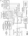
- FIG. 3illustrates an example sensor fusion system 300 according to various examples.
- the sensor fusion system 300can include a measurement integration system 310 to receive raw measurement data 301 from multiple sensors mounted in a vehicle.
- the measurement integration system 310can generate an environmental model 315 for the vehicle, which can be populated with the raw measurement data 301 .
- the measurement integration system 310can include a spatial alignment unit 311 to correlate measurement coordinate fields of the sensors to an environmental coordinate field for the environmental model 315 .
- the measurement integration system 310can utilize this correlation to convert or translate locations for the raw measurement data 301 within the measurement coordinate fields into locations within the environmental coordinate field.
- the measurement integration system 310can populate the environmental model 315 with the raw measurement data 301 based on the correlation between the measurement coordinate fields of the sensors to the environmental coordinate field for the environmental model 315 .
- the measurement integration system 310also can temporally align the raw measurement data 301 from different sensors in the sensor system.
- the measurement integration system 310can include a temporal alignment unit 312 to assign time stamps to the raw measurement data 301 based on when the sensor captured the raw measurement data 301 , when the raw measurement data 301 was received by the measurement integration system 310 , or the like.
- the temporal alignment unit 312can convert a capture time of the raw measurement data 301 provided by the sensors into a time corresponding to the sensor fusion system 300 .
- the measurement integration system 310can annotate the raw measurement data 301 populated in the environmental model 315 with the time stamps for the raw measurement data 301 .
- the time stamps for the raw measurement data 301can be utilized by the sensor fusion system 300 to group the raw measurement data 301 in the environmental model 315 into different time periods or time slices.
- a size or duration of the time periods or time slicescan be based, at least in part, on a refresh rate of one or more sensors in the sensor system.
- the sensor fusion system 300can set a time slice to correspond to the sensor with a fastest rate of providing new raw measurement data 301 to the sensor fusion system 300 .
- the measurement integration system 310can include an ego motion unit 313 to compensate for movement of at least one sensor capturing the raw measurement data 301 , for example, due to the vehicle driving or moving in the environment.
- the ego motion unit 313can estimate motion of the sensor capturing the raw measurement data 301 , for example, by utilizing tracking functionality to analyze vehicle motion information, such as global positioning system (GPS) data, inertial measurements, vehicle odometer data, video images, or the like.
- GPSglobal positioning system
- the tracking functionalitycan implement a Kalman filter, a Particle filter, optical flow-based estimator, or the like, to track motion of the vehicle and its corresponding sensors relative to the environment surrounding the vehicle.
- the ego motion unit 313can utilize the estimated motion of the sensor to modify the correlation between the measurement coordinate field of the sensor to the environmental coordinate field for the environmental model 315 .
- This compensation of the correlationcan allow the measurement integration system 310 to populate the environmental model 315 with the raw measurement data 301 at locations of the environmental coordinate field where the raw measurement data 301 was captured as opposed to the current location of the sensor at the end of its measurement capture.
- the measurement integration system 310may receive objects or object lists 302 from a variety of sources.
- the measurement integration system 310can receive the object list 302 from sources external to the vehicle, such as in a vehicle-to-vehicle (V2V) communication, a vehicle-to-infrastructure (V2I) communication, a vehicle-to-pedestrian (V2P) communication, a vehicle-to-device (V2D) communication, a vehicle-to-grid (V2G) communication, or generally a vehicle-to-everything (V2X) communication.
- V2Vvehicle-to-vehicle
- V2Ivehicle-to-infrastructure
- V2Pvehicle-to-pedestrian
- V2Dvehicle-to-device
- V2Gvehicle-to-grid
- V2Xvehicle-to-everything
- the measurement integration system 310also can receive the objects or an object list 302 from other systems internal to the vehicle, such as from a human machine interface, mapping systems, localization system, driving functionality system, vehicle control system, or the vehicle may be equipped with at least one sensor that outputs the object list 302 rather than the raw measurement data 301 .
- the measurement integration system 310can receive the object list 302 and populate one or more objects from the object list 302 into the environmental model 315 along with the raw measurement data 301 .
- the object list 302may include one or more objects, a time stamp for each object, and optionally include a spatial metadata associated with a location of objects in the object list 302 .
- the object list 302can include speed measurements for the vehicle, which may not include a spatial component to be stored in the object list 302 as the spatial metadata.
- the measurement integration system 310also can annotate the environmental model 315 with the confidence level for the object from the object list 302 .
- the sensor fusion system 300can include an object detection system 320 to receive the environmental model 315 from the measurement integration system 310 .
- the sensor fusion system 300can include a memory system 330 to store the environmental model 315 from the measurement integration system 310 .
- the object detection system 320may access the environmental model 315 from the memory system 330 .
- the object detection system 320can analyze data stored in the environmental model 315 to detect a sensor detection event or at least one object.
- the sensor fusion system 300can populate the environment model 315 with an indication of the sensor detection event or detected object at a location in the environmental coordinate field corresponding to the detection.
- the sensor fusion system 300also can identify a confidence level associated with the detection, which can be based on at least one of a quantity, a quality, or a sensor diversity of raw measurement data 301 utilized in detecting the sensor detection event or detected object.
- the sensor fusion system 300can populate the environment model 315 with the confidence level associated with the detection.
- the object detection system 320can annotate the environmental model 315 with object annotations 324 , which populates the environmental model 315 with the detected sensor detection event or detected object and corresponding confidence level of the detection.
- the object detection system 320can include a sensor event detection and fusion unit 321 to monitor the environmental model 315 to detect sensor measurement events.
- the sensor measurement eventscan identify locations in the environmental model 315 having been populated with the raw measurement data 301 for a sensor, for example, above a threshold corresponding to noise in the environment.
- the sensor event detection and fusion unit 321can detect the sensor measurement events by identifying changes in intensity within the raw measurement data 301 over time, changes in reflections within the raw measurement data 301 over time, change in pixel values, or the like.
- the sensor event detection and fusion unit 321can analyze the raw measurement data 301 in the environmental model 315 at the locations associated with the sensor measurement events to detect one or more sensor detection events.
- the sensor event detection and fusion unit 321can identify a sensor detection event when the raw measurement data 301 associated with a single sensor meets or exceeds sensor event detection threshold.
- the sensor event detection and fusion unit 321can analyze an image captured by a camera in the raw measurement data 301 to identify edges in the image, shapes in the image, or the like, which the sensor event detection and fusion unit 321 can utilize to identify a sensor detection event for the image.
- the sensor event detection and fusion unit 321also may analyze groups of intensity points in raw measurement data 301 corresponding to a lidar sensor or groups reflections in raw measurement data 301 corresponding to a radar sensor to determine the a sensor detection event for raw measurement data 301 for those sensors.
- the sensor event detection and fusion unit 321can combine the identified sensor detection event for a single sensor with raw measurement data 301 associated with one or more sensor measurement events or sensor detection events captured by at least another sensor to generate a fused sensor detection event.
- the fused sensor detection eventcan correspond to raw measurement data 301 from multiple sensors, at least one of which corresponds to the sensor detection event identified by the sensor event detection and fusion unit 321 .
- the object detection system 320can include a pre-classification unit 322 to assign a pre-classification to the sensor detection event or the fused sensor detection event.
- the pre-classificationcan correspond to a type of object, such as another vehicle, a pedestrian, a cyclist, an animal, a static object, or the like.
- the pre-classification unit 322can annotate the environmental model 315 with the sensor detection event, the fused sensor detection event and/or the assigned pre-classification.
- the object detection system 320also can include a tracking unit 323 to track the sensor detection events or the fused sensor detection events in the environmental model 315 over time, for example, by analyzing the annotations in the environmental model 315 , and determine whether the sensor detection event or the fused sensor detection event corresponds to an object in the environmental coordinate system.
- the tracking unit 323can track the sensor detection event or the fused sensor detection event utilizing at least one state change prediction model, such as a kinetic model, a probabilistic model, or other state change prediction model.
- the tracking unit 323can select the state change prediction model to utilize to track the sensor detection event or the fused sensor detection event based on the assigned pre-classification of the sensor detection event or the fused sensor detection event by the pre-classification unit 322 .
- the state change prediction modelmay allow the tracking unit 323 to implement a state transition prediction, which can assume or predict future states of the sensor detection event or the fused sensor detection event, for example, based on a location of the sensor detection event or the fused sensor detection event in the environmental model 315 , a prior movement of the sensor detection event or the fused sensor detection event, a classification of the sensor detection event or the fused sensor detection event, or the like.
- the tracking unit 323 implementing the kinetic modelcan utilize kinetic equations for velocity, acceleration, momentum, or the like, to assume or predict the future states of the sensor detection event or the fused sensor detection event based, at least in part, on its prior states.
- the tracking unit 323may determine a difference between the predicted future state of the sensor detection event or the fused sensor detection event and its actual future state, which the tracking unit 323 may utilize to determine whether the sensor detection event or the fused sensor detection event is an object. After the sensor detection event or the fused sensor detection event has been identified by the pre-classification unit 322 , the tracking unit 323 can track the sensor detection event or the fused sensor detection event in the environmental coordinate field associated with the environmental model 315 , for example, across multiple different sensors and their corresponding measurement coordinate fields.
- the object tracking unit 323can annotate the environmental model 315 to indicate the presence of the object.
- the tracking unit 323can continue tracking the detected object over time by implementing the state change prediction model for the object and analyzing the environmental model 315 when updated with additional raw measurement data 301 . After the object has been detected, the tracking unit 323 can track the object in the environmental coordinate field associated with the environmental model 315 , for example, across multiple different sensors and their corresponding measurement coordinate fields.
- the sensor fusion system 300can include an analysis system 340 to develop information from the annotated environmental model 332 for utilization by a driving functionality system which is providing input to a vehicle control system.
- the analysis system 340can include an object trajectory prediction unit 341 to generate a projected object trajectory 343 of a tracked object proximate to the vehicle.
- the object trajectory prediction unit 341can access the annotated environmental model 332 from the memory system 330 or receive them directly from the measurement integration system 310 and/or the object detection system 320 .
- the object trajectory prediction unit 341can utilize the annotated environmental model 332 along with the state change prediction model corresponding to the tracked object to predict movement of the tracked object relative to the vehicle in the future.
- the object trajectory prediction unit 341can generate a range of expected trajectories along with probabilities associated with the expected trajectories in the range.
- the object trajectory prediction unit 341can annotate the environmental model 315 with the projected object trajectory 343 , for example, by storing the projected object trajectory 343 in the annotated environmental model 332 residing the in memory system 330 .
- the analysis system 340can include a localization system 342 to utilize the annotated environmental model 332 to determine a location of the vehicle.
- the localization system 342can receive the global positioning system (GPS) information and map data 331 , for example, from the memory system 330 .
- the map data 331can include topographical maps, terrain maps, street view maps, or the like, of an area corresponding to a location of the vehicle.
- the map data 331can include features, such as roadways, signs, traffic signals, transit crossings, pedestrian crossings, buildings, trees, structures, terrain gradients, topographical edges, photogrammetry, intensity gradients, or like.
- the localization system 342can correlate data or annotations in the annotated environmental model 332 to landmarks or objects in the map data 331 .
- the localization system 342can access the annotated environmental model 332 from the memory system 330 or receive them directly from the measurement integration system 310 and/or the object detection system 320 .
- the correlation between the map data 331 and the annotated environmental model 332can identify a vehicle location 344 describing a position of the vehicle relative to the map data 331 .
- the localization system 342also can utilize the annotated environmental model 332 to determine in-lane localization for the vehicle.
- the in-lane localizationcan identify the vehicle location 344 describing the position of the vehicle relative to a lane in a roadway.
- the localization system 342can selectively perform in-lane localization and map data correlation with the annotated environmental model 332 to identify the vehicle location 344 , for example, based on a driving situation, processing resource utilization, or the like.
- the localization system 342can output the vehicle location 344 , which, in some embodiments, can be stored by the memory system 330 as another annotation to the annotated environmental model 332 .
- the sensor fusion system 300can include a publish-subscribe system 350 to communicate with devices, components, or applications external to the sensor fusion system 300 .
- the publish-subscribe system 350can allow processes or applications in a driving functionality system to receive information from the annotated environmental model 332 or to provide annotations to the annotated environmental model 332 .
- the publish-subscribe system 350can receive subscriptions 351 , for example, from a driving functionality system, a vehicle control system, or other devices external from the sensor fusion system 300 .
- the subscriptions 351may identify at least one region of interest in the annotated environmental model 315 for a region of interest management system 360 to monitor for data or events.
- the region of interestcan have a spatial description, for example, a portion of the environmental coordinate field in the annotated environmental model 332 .
- the region of interestcan have a temporal description, for example, as time window or a time offset during which the region of interest management system 360 can monitor the annotated environmental model 332 .
- the subscriptions 351can include additional monitoring information, such as a type of data to monitor, a type of detection, and whether to enable dynamic adaptation of the identified region of interest.
- the publish-subscribe system 350can provide at least a portion of the subscriptions 351 to the region of interest management system 360 as subscription information 362 .
- the region of interest management system 360can analyze the subscription information 362 to identify at least one region of interest of the annotated environmental model 332 to monitor for data or events.
- the region of interest management system 360can include a registry of the one or more regions of interest that the region of interest management system 360 monitors based on the subscription information 362 from the publish-subscribe system 350 .
- the region of interest management system 360can monitor the environmental model 332 , for example, by accessing the memory system 330 , to identify data and events corresponding to at least one of the regions of interest in the registry.
- the region of interest management system 360detects data or an event corresponding to a region of interest in a subscription 362
- the region of interest management system 360can forward detection information to the publish-subscribe system 350 .
- the detection informationcan identify the region of interest associated with the detection, the detected portion of the annotated environmental model 332 or a reference to the detected portion of the annotated environmental model 332 in the memory system 330 , a type of detection or the like.
- the publish-subscribe system 350can utilize the detection information to generate and output event data 352 to the devices, systems, applications, or components that provided the publish-subscribe system 350 the subscription 351 describing the region of interest associated with the detection.
- the region of interest management system 360also can dynamically adapt the region of interest for one or more of the subscriptions 351 , for example, based on the mode of operation of the vehicle, a planned path or route the vehicle expects to traverse, features in map data 331 , or the like.
- the region of interest management system 360 or other portion of the sensor fusion system 300can identify locations of upcoming traffic lights or signage and suggest the process or component in the driving functionality system expand its region of interest or add a new region of interest to include the upcoming traffic lights or signage.
- the region of interest management system 360 or other portion of the system 300can identify the vehicle plans to make a turn and expand its region of interest to include areas corresponding to the road after making the turn.
- the sensor fusion system 300can include and/or interface with a situational awareness system 370 .
- the situational awareness system 370can be a component of the sensor fusion system 300 .
- the situational awareness system 370can be a component of the driving functionality system 120 of FIG. 1 .
- the situation awareness system 370can include a classifier that determines a situational annotation 372 based on input from various systems.
- the situational awareness system 370receives the annotated environmental model 332 from the memory system 330 , projected object trajectory data 343 from the object trajectory prediction unit 341 , map correlations from the localization unit 342 , region of interest data 364 from the region of interest management system 360 , and/or other situational context data.
- the situational awareness system 370uses the various input data (that is, situational context data) to classify the current situation of the vehicle.
- the classification resultis represented by a situational annotation 372 .
- the situational annotation 372 of the vehiclecan include and/or represent an awareness of the vehicle surroundings, the state of the vehicle, and/or any other data describing the situation in which the vehicle is driving or will be driving in the future.
- a situational annotation 372 or parts of the situational annotation 372may be output to various systems, units, or devices that subscribe to the situational awareness system 370 .
- the publish-subscribe system 350can receive subscriptions 351 , for example, from a driving functionality system, a vehicle control system, or other devices to the situational awareness system 370 .
- a driving functionality systemcan subscribe to the situation awareness system 370 via the publish-subscribe system 350 .
- Subscription information 362 describing the parameters of the subscriptioncan be passed to the situational awareness system 370 (e.g., via the region of interest management system 360 ).
- the situational annotation 372can be provided to the memory system 330 .
- the memory system 330can cache the situational annotation 372 for distribution to driving functionality systems that have subscribed to the situational awareness system 370 via, for example, the publish-subscribe system 350 .
- FIG. 4illustrates an example flowchart for populating and annotating an environmental model according to various examples.
- the steps of the processcan be carried out by a computing system, such as sensor fusion unit 300 of FIG. 1 .
- time stamp raw measurement datais received from a sensor system.
- the computing systemcan assign time stamps to the raw measurement data based on when each sensor captured the raw measurement data, when the raw measurement data was received by the computing system, or the like.
- the computing systemmay adjust the assigned time stamp by a preset time delay associated with the transmission of the raw measurement data from the sensor system to the computing system.
- the computing systemcan assign the timestamps to the raw measurement data by converting a capture time of the raw measurement data provided by the sensor system into a global time of the computing system.
- the measurement coordinate fields of sensorsare spatially aligned to an environmental coordinate field.
- the computing systemcan identify where the measurement coordinate fields of the sensors fall within the environmental coordinate field for the environmental model, for example, based on where the sensors are mounted in the vehicle and the type of sensor associated with each measurement coordinate field.
- the environmental modelis populated with the raw measurement data based on the spatial alignment.
- the computing systemcan utilize the correlation between the measurement coordinate fields of sensors to the environmental coordinate field to convert or translate locations of the raw measurement data into locations within the environmental model.
- the computing systemcan populate the environmental model with the raw measurement data based on the correlation between the measurement coordinate fields of the sensors to the environmental coordinate field for the environmental model.
- the environmental modelis annotated with the time stamps for the raw measurement data.
- the time stamps for the raw measurement datacan be utilized by the computing system to group the raw measurement data in the environmental model into different time periods or time slices.
- a size or duration of the time periods or time slicescan be based on a refresh rate of one or more sensors in the sensor system.
- the computing systemcan set a time slice to correspond to the sensor with a fastest rate of providing new raw measurement data to the computing system.
- FIG. 4shows blocks 410 - 440 being performed in a particular order, in some embodiments, the computing system can perform operations in the blocks 410 - 440 in a different order or the operations in some of the blocks 410 - 440 may be merged or divided into additional blocks.
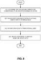
- FIG. 5illustrates an example flowchart for determining a situational annotation of a vehicle according to various examples.
- an annotated environmental model associated with a vehicleis received at, for example, a situational awareness system.
- the environmental modelcan be generated and/or updated using the techniques outlined in FIG. 4 .
- the annotated environmental modelcan include data from a plurality of modalities, such as raw measurement data from one or more sensors, fused sensor data, object level data, data from external sources (e.g., V2X data), high level sensor data, projected object trajectory, results of path planning operation, matched map data, and the like.
- an environmental modelis updated continuously in real time as the vehicle is in operation.
- the continuously updated environmental modelcan provide an annotated description of the surroundings at the current time, all times prior to a current time, and/or a predicted environmental model.
- a predicted environmental modelmay include predictions of the trajectory of the vehicle and these predicted trajectories may be included in the annotated environmental model.
- the annotated environmental modelis continuously populated and annotated with raw measurement data from various sensors of the vehicle, information detected by the sensor fusion system, lists of objects and/or class of objects, high level data, data from external sources (e.g., map data, data from other vehicles, etc.), and/or any other relevant data.
- the environmental modelcan also take into account various other data including map data matched with the environmental model, dynamic and static obstacles, predictions of object trajectories, path-planner's description of the vehicle's own trajectory, free space, lane location, object classes, regions-of-interest and/or all other annotations added to the environmental model.
- a situational annotation of the vehicleis determined based on the environmental model.
- a situational annotationcan include a classification of the entire surroundings of a vehicle, the internal state of the vehicle, and/or other vehicle-related information relative to certain point in time and/or location.
- a machine learning approachis used to classify the situational annotation of the vehicle.
- the annotated environmental model or portions thereofcan be provided as input to a machine learning module, such as a neural network or other machine learning module.
- the machine learning modulecan classify a situation of the vehicle based on the annotated environmental model.
- the machine learning modulecan be trained to classify various situations that the vehicle encounters.
- the machine learning modulecan be trained using any suitable machine learning training approach (e.g., supervised, unsupervised learning, etc.) on labeled data.
- the data used to train the machine learning modulemay include sensor data from multiple modalities, which can include data from multiple sensors, multiple levels of data (e.g., low level data, high level data), data from external sources, and the like.
- the situational awareness systemcan adapt and be updated during the lifecycle of the vehicle to classify new situations. For example, updates may be received from a backbone infrastructure to update or improve the situational awareness system to classify new situations.
- data from an annotated environmental modelis provided to the machine learning module, and the machine learning module classifies a situation associated with the vehicle.
- the classificationcan be included in or represented by a situational annotation. For example, spatially and/or temporally aligned and/or annotated raw measurement data, sensor fusion data, high level data, and/or other data included in an annotated environmental model is provided as input to a machine learning module.
- the machine learning moduledetermines a situational annotation by classifying the data from the annotated environmental model.
- a predicted environmental model, localization information, region of interest information, and/or other informationare also provided to the classifier.
- the classifiercan determine a situational annotation based on these additional inputs.
- a situational annotationis output.
- the situational annotationmay include the result of a situation classification.
- the situational annotationis output to a system, such as a driving functionality system, a region of interest manager, a path planning decision system, an external server, and/or any other system.
- a driving functionality systemcan utilize the situational annotation to control the operation of the vehicle.
- a forward braking assistantcan use situational annotation data to decide whether to apply full braking or implement a swerving maneuver.
- a region of interest management systemmay use the situational annotation to modify a region of interest monitored by a particular driving functionality system.
- the situational annotationmay indicate that a situation is unclassifiable and/or uncertain.
- data from the annotated environmental modelmay not be readily classifiable, and it may be determined that the situation is unknown and/or partially unknown.
- the situational contextcan be provided to an external server and/or backbone infrastructure for classification or further analysis as discussed in detail below.
- the annotated environmental model, parts of the annotated environmental model, situational annotation, and/or other datacan be stored to a memory associated with the vehicle (such as memory system 330 of FIG. 3 ).
- the stored portions of the environmental model and situational annotationcan be used to evaluate an incident associated with the vehicle.
- a vehiclemay be involved in an incident, such as an accident, a near miss, or the like, and a stored portion of the environmental model and situational annotation can be used to analyze the incident.
- the stored portion of the environmental model and situational annotationcan be passed to backbone infrastructure and/or other entity for analysis.
- the stored data associated with the eventcan be used to improve the functionality of an automated driving system (e.g., to avoid the incident in future).
- Updates to a situational awareness system, a driving functionality system, and/or other systemcan be made based on the data and provided to vehicles in, for example, an over-the-air update.
- the stored portion of the environmental model and situational annotation associated with an incidentmay also be used by an insurance company, vehicle safety organization, the police, or other entity to analyze the incident.
- FIG. 6illustrates an example block diagram for determining a situational annotation of a vehicle according to various examples.
- the functionality described in FIG. 6can be carried out in a situational awareness system included, for example, in sensor fusion system 300 of FIG. 3 or alternatively in the driving functionality system 120 of FIG. 1 .
- an annotated environmental model 610a predicted environmental model 620 , localization information 630 , region of interest data 650 , and/or other situational context data are provided to a situational awareness system 600 .
- the situational awareness system 600can include a classifier, such as a machine learning classifier, a neural network, or the like.
- the annotated environmental model 610can include data from a plurality of modalities, such as raw measurement data from sensors on the vehicle, data generated and/or annotated by a sensor fusion system, data from external sources, and the like.
- the data in the annotated environmental model 610can be temporally and/or spatially aligned using the techniques disclosed herein.
- An annotated environmental model 610can be provided to the situational awareness system 600 . In some cases, only portions of the annotated environmental model 610 , for example, including data related to a spatial area over a period of time can be provided to the situational awareness system 600 .
- a classifier included in the situational awareness system 600can use this data to generate a situational annotation 640 .
- a predicted environmental model 620is provided to the situational awareness system 600 .
- the predicted environmental model 620can be generated by an object trajectory prediction system, such as object trajectory prediction unit 341 of FIG. 3 .
- the predicted environmental model 620can include predicted trajectories of various objects, such as tracked objects in the annotated environmental model 610 .
- the annotated environmental model 610 and a state change prediction model corresponding to a tracked objectcan be used to predict movement of the tracked object relative to the vehicle in the future. This predicted trajectory can be included in the predicted environmental model 620 .
- the predicted trajectory of objectscan influence the classification of a situation around a vehicle and thus the situational annotation 640 .
- the predicted environmental model 620can also include a predicted trajectory of the vehicle.
- the predicted environmental model 620can include a path planner's description of the vehicle's trajectory.
- the predicted trajectory of the vehiclemay define predicted future locations of the vehicle, which may affect the situation annotation 64 .
- localization information 630is provided as input to the situational awareness system 600 .
- Localization information 630can be generated by a localization unit, such as localization unit 342 of FIG. 3 .
- Localization information 630can include correlations between raw measurement data from various sensors on the vehicle and features (e.g., landmarks, roadways, signs, traffic signals, and like) in map data. The correlations can identify a position of the vehicle relative to features included in map data.
- localization information 630can correlate a tracked object, a tracked sensor detection event, or a tracked fused sensor detection event in the annotated environmental model 610 relative to a feature, such as the location of a roadway sign, in map data.
- the localization information 630may weigh in to the classification of situation associated with the vehicle, and as a result may weigh into the situational annotation determined by the situational awareness system 600 .
- the region of interest data 650is provided to the situational awareness system 600 .
- Region of interest data 650may be generated by a region of interest management system, such as region of interest management system 360 of FIG. 3 .
- Region of interest data 650may define a spatial region (such a portion of a coordinate field) and temporal region (such as a time window) of the annotated environmental model 610 .
- the region of interest data 650 input to the situational awareness system 600may focus the classifier engine on data associated with the spatial and temporal regions defined by the region of interest data 650 . For example, raw sensor data, detection events, tracked objects, fused sensor data, and/or other data included in the region of interest are provided to the situational awareness system 600 . Data from outside the region of interest may be filtered out.
- a situational annotation 640is determined using a classifier associated with and/or comprising the situational awareness system 600 .
- the situational annotation 640can represent the situation in which the vehicle is driving, the state of the vehicle, and/or other aspects relevant to the operation of the vehicle and/or its systems.
- the situation annotation 640can be output to any driving functionality system and/or other systems subscribing to the situational awareness system 600 .
- the situational annotation 640is output to a region of interest manager 650 .
- the region of interest manager 650can update one or more regions of interest based on the situational annotation 640 .
- a region of interest subscribed to by a forward braking assist systemmay be enlarged based on situational annotation 640 indicating that the vehicle is traveling into an intersection including multiple tracked objects, such as pedestrians, bicyclists, and the like, and a detection event indicating as of yet unclassified object is moving across the path in front of the vehicle. Adjustment of the region of interest is discussed in detail below.
- FIG. 7illustrates an example flowchart for adjusting a region of interest according to various examples.
- a subscription to a region of interest in an environmental modelis received.
- the subscriptioncan be received at, for example, a region of interest management system from an event management system (e.g., a publish-subscribe system).
- the subscription informationcan identify at least one region of interest in an environmental model.
- the region of interestcan have a spatial description, for example, a portion of the environmental coordinate field in the environmental model.
- the region of interestcan also have a temporal description, for example, as a time window or a time offset during which the region of interest management system can monitor the environmental model.
- a situational annotationis received.
- the situational annotationcan be received at the region of interest management system from a situational awareness system, such as situational awareness system 370 of FIG. 3 .
- the situational awareness systemmay provide the region of interest management system an updated situational annotation periodically, when there is a change in a situational annotation that would be relevant to a region of interest, and/or at other times.
- a region of interestis adjusted based on the situational annotation.
- a region of interestcorresponds to a forward braking assistant.
- the region of interest managermay receive a situational annotation indicating that the vehicle is approaching an intersection. Prior to the intersection the region of interest in the environmental model may include the region in front of the vehicle. As the vehicle approaches the intersection the region of interest may be expanded to include side sensor fields to detect events on the side of the vehicle, such as potential vulnerable road users, pedestrian crossings, bike lanes, and the like, and to include cross-traffic sensors to detect events to the sides of the vehicle, such as vehicles, pedestrians, and the like crossing in front of the vehicle.
- the region of interestmay dynamically adapt to include portions of the roadway after the turn.
- the situational annotationmay take into account locational information regarding another vehicle in an adjacent lane of traffic, which may prompt the region of interest to be expanded to monitor the other vehicle for possible lane change.
- FIG. 8illustrates an example flowchart for updating a situational awareness classifier according to various examples.
- a situational awareness systemdetermines that a situation cannot be classified with high enough confidence.
- a situational awareness systemmay determine that aspects of the environment around the vehicle, the internal state of the vehicle, and/or other situation-related data are unknown.
- portions of an annotated environment modelmay include data that is not classifiable by a situational awareness system.
- the situational awareness systemcan determine that a situation is uncertain when a classification confidence is beneath a certain threshold.
- the situational awareness systemprovides data associated with the uncertain situation to an external node.
- Data describing the uncertain or new situationsuch as environmental model data, predicted environmental model data, localization information, region of interest information, situational annotation, and/or any other information related to the uncertain situation is provided to an external node.
- an appropriate amount of situational contextcan be uploaded to the external node.
- the external nodecan include an external server, backbone system, and/or other node in an infrastructure associated with the situational awareness system and/or AD/ADAS systems.
- the external nodeincludes additional computing resources to evaluate and classify the uncertain and/or new situation.
- a backbone systemcan utilize machine learning approaches with more computing power and more training data in order to take the new situation into account.
- the backbone systemcan generate update data to re-parameterize the machine learning system in the vehicle. This update information can be provided to the situational awareness system and/or situational awareness systems associated with multiple vehicles in a fleet.
- update informationis received at the situational awareness system.
- the update datacan be received, for example, during an over-the-air software update.
- the situational classifier systemis updated.
- the update informationcan include parameters, such as classifier parameters, and/or other information.
- the update informationcan be used to improve the situational awareness classifier (e.g., machine learning system) to properly classify the new situation and generate situational annotation data as prescribed by the backbone system.
- object recognition and classification techniquesmay be implemented using computer-executable software instructions executed by one or more programmable computing devices. Because these embodiments may be implemented using software instructions, the components and operation of a programmable computer system on which various embodiments may be employed will be described below.
- FIGS. 9 and 10illustrate an example of a computer system of the type that may be used to implement various embodiments.
- a computing device 901such as a programmable computer.
- FIG. 9shows an illustrative example of a computing device 901 .
- the computing device 901includes a computing unit 903 with a processing unit 905 and a system memory 907 .
- the processing unit 905may be any type of programmable electronic device for executing software instructions, but will conventionally be a microprocessor.
- the system memory 907may include both a read-only memory (ROM) 909 and a random access memory (RAM) 911 .
- both the read-only memory (ROM) 909 and the random access memory (RAM) 911may store software instructions for execution by the processing unit 905 .
- the processing unit 905 and the system memory 907are connected, either directly or indirectly, through a bus 913 or alternate communication structure, to one or more peripheral devices 917 - 923 .
- the processing unit 905 or the system memory 907may be directly or indirectly connected to one or more additional memory storage devices, such as a hard disk drive 917 , which can be magnetic and/or removable, a removable optical disk drive 919 , and/or a flash memory card.
- the processing unit 905 and the system memory 907also may be directly or indirectly connected to one or more input devices 921 and one or more output devices 923 .
- the input devices 921may include, for example, a keyboard, a pointing device (such as a mouse, touchpad, stylus, trackball, or joystick), a scanner, a camera, and a microphone.
- the output devices 923may include, for example, a monitor display, a printer and speakers.
- one or more of the peripheral devices 917 - 923may be internally housed with the computing unit 903 .
- one or more of the peripheral devices 917 - 923may be external to the housing for the computing unit 903 and connected to the bus 913 through, for example, a Universal Serial Bus (USB) connection.
- USBUniversal Serial Bus
- the computing unit 903may be directly or indirectly connected to a network interface 915 for communicating with other devices making up a network.
- the network interface 915can translate data and control signals from the computing unit 903 into network messages according to one or more communication protocols, such as the transmission control protocol (TCP) and the Internet protocol (IP).
- TCPtransmission control protocol
- IPInternet protocol
- the network interface 915may employ any suitable connection agent (or combination of agents) for connecting to a network, including, for example, a wireless transceiver, a modem, or an Ethernet connection.
- connection agentor combination of agents
- computing device 901is illustrated as an example only, and it not intended to be limiting. Various embodiments may be implemented using one or more computing devices that include the components of the computing device 901 illustrated in FIG. 9 , which include only a subset of the components illustrated in FIG. 9 , or which include an alternate combination of components, including components that are not shown in FIG. 9 . For example, various embodiments may be implemented using a multi-processor computer, a plurality of single and/or multiprocessor computers arranged into a network, or some combination of both.
- the processor unit 905can have more than one processor core.
- FIG. 10illustrates an example of a multi-core processor unit 905 that may be employed with various embodiments.
- the processor unit 905includes a plurality of processor cores 1001 A and 1001 B.
- Each processor core 1001 A and 1001 Bincludes a computing engine 1003 A and 1003 B, respectively, and a memory cache 1005 A and 1005 B, respectively.
- a computing engine 1003 A and 1003 Bcan include logic devices for performing various computing functions, such as fetching software instructions and then performing the actions specified in the fetched instructions.
- Each computing engine 1003 A and 1003 Bmay then use its corresponding memory cache 1005 A and 1005 B, respectively, to quickly store and retrieve data and/or instructions for execution.
- Each processor core 1001 A and 1001 Bis connected to an interconnect 1007 .
- the particular construction of the interconnect 1007may vary depending upon the architecture of the processor unit 905 .
- the interconnect 1007may be implemented as an interconnect bus.
- the interconnect 1007may be implemented as a system request interface device.
- the processor cores 1001 A and 1001 Bcommunicate through the interconnect 1007 with an input/output interface 1009 and a memory controller 1010 .
- the input/output interface 1009provides a communication interface between the processor unit 905 and the bus 913 .
- the memory controller 1010controls the exchange of information between the processor unit 905 and the system memory 907 .
- the processor unit 905may include additional components, such as a high-level cache memory accessible shared by the processor cores 1001 A and 1001 B. It also should be appreciated that the description of the computer network illustrated in FIG. 9 and FIG. 10 is provided as an example only, and it not intended to suggest any limitation as to the scope of use or functionality of alternate embodiments.
- the system and apparatus described abovemay use dedicated processor systems, micro controllers, programmable logic devices, microprocessors, or any combination thereof, to perform some or all of the operations described herein. Some of the operations described above may be implemented in software and other operations may be implemented in hardware. Any of the operations, processes, and/or methods described herein may be performed by an apparatus, a device, and/or a system substantially similar to those as described herein and with reference to the illustrated figures.
- the processing devicemay execute instructions or “code” stored in a computer-readable memory device.
- the memory devicemay store data as well.
- the processing devicemay include, but may not be limited to, an analog processor, a digital processor, a microprocessor, a multi-core processor, a processor array, a network processor, or the like.
- the processing devicemay be part of an integrated control system or system manager, or may be provided as a portable electronic device configured to interface with a networked system either locally or remotely via wireless transmission.
- the processor memorymay be integrated together with the processing device, for example RAM or FLASH memory disposed within an integrated circuit microprocessor or the like.
- the memory devicemay comprise an independent device, such as an external disk drive, a storage array, a portable FLASH key fob, or the like.
- the memory and processing devicemay be operatively coupled together, or in communication with each other, for example by an I/O port, a network connection, or the like, and the processing device may read a file stored on the memory.
- Associated memory devicesmay be “read only” by design (ROM) by virtue of permission settings, or not.
- memory devicesmay include, but may not be limited to, WORM, EPROM, EEPROM, FLASH, NVRAM, OTP, or the like, which may be implemented in solid state semiconductor devices.
- Other memory devicesmay comprise moving parts, such as a known rotating disk drive. All such memory devices may be “machine-readable” and may be readable by a processing device.
- Computer-readable storage mediummay include all of the foregoing types of computer-readable memory devices, as well as new technologies of the future, as long as the memory devices may be capable of storing digital information in the nature of a computer program or other data, at least temporarily, and as long at the stored information may be “read” by an appropriate processing device.
- the term “computer-readable”may not be limited to the historical usage of “computer” to imply a complete mainframe, mini-computer, desktop or even laptop computer.
- “computer-readable”may comprise storage medium that may be readable by a processor, a processing device, or any computing system. Such media may be any available media that may be locally and/or remotely accessible by a computer or a processor, and may include volatile and non-volatile media, and removable and non-removable media, or any combination thereof.
- a program stored in a computer-readable storage mediummay comprise a computer program product.
- a storage mediummay be used as a convenient means to store or transport a computer program.
- the operationsmay be described as various interconnected or coupled functional blocks or diagrams. However, there may be cases where these functional blocks or diagrams may be equivalently aggregated into a single logic device, program or operation with unclear boundaries.
Landscapes
- Engineering & Computer Science (AREA)
- Physics & Mathematics (AREA)
- Theoretical Computer Science (AREA)
- General Physics & Mathematics (AREA)
- Software Systems (AREA)
- Artificial Intelligence (AREA)
- Mathematical Physics (AREA)
- Evolutionary Computation (AREA)
- Medical Informatics (AREA)
- General Engineering & Computer Science (AREA)
- Data Mining & Analysis (AREA)
- Computing Systems (AREA)
- Automation & Control Theory (AREA)
- Computer Vision & Pattern Recognition (AREA)
- Multimedia (AREA)
- Remote Sensing (AREA)
- Aviation & Aerospace Engineering (AREA)
- Game Theory and Decision Science (AREA)
- Health & Medical Sciences (AREA)
- Business, Economics & Management (AREA)
- Mechanical Engineering (AREA)
- Transportation (AREA)
- Radar, Positioning & Navigation (AREA)
- Computer Networks & Wireless Communication (AREA)
- Signal Processing (AREA)
- Probability & Statistics with Applications (AREA)
- Computational Mathematics (AREA)
- Mathematical Analysis (AREA)
- Mathematical Optimization (AREA)
- Pure & Applied Mathematics (AREA)
- Algebra (AREA)
- Traffic Control Systems (AREA)
- Control Of Driving Devices And Active Controlling Of Vehicle (AREA)
Abstract
Description
Claims (19)
Priority Applications (2)
| Application Number | Priority Date | Filing Date | Title |
|---|---|---|---|
| US15/260,149US10678240B2 (en) | 2016-09-08 | 2016-09-08 | Sensor modification based on an annotated environmental model |
| PCT/IB2017/055438WO2018047114A2 (en) | 2016-09-08 | 2017-09-08 | Situational awareness determination based on an annotated environmental model |
Applications Claiming Priority (1)
| Application Number | Priority Date | Filing Date | Title |
|---|---|---|---|
| US15/260,149US10678240B2 (en) | 2016-09-08 | 2016-09-08 | Sensor modification based on an annotated environmental model |
Publications (2)
| Publication Number | Publication Date |
|---|---|
| US20180067488A1 US20180067488A1 (en) | 2018-03-08 |
| US10678240B2true US10678240B2 (en) | 2020-06-09 |
Family
ID=60569953
Family Applications (1)
| Application Number | Title | Priority Date | Filing Date |
|---|---|---|---|
| US15/260,149Active2036-10-01US10678240B2 (en) | 2016-09-08 | 2016-09-08 | Sensor modification based on an annotated environmental model |
Country Status (2)
| Country | Link |
|---|---|
| US (1) | US10678240B2 (en) |
| WO (1) | WO2018047114A2 (en) |
Cited By (6)
| Publication number | Priority date | Publication date | Assignee | Title |
|---|---|---|---|---|
| US20200250514A1 (en)* | 2019-01-31 | 2020-08-06 | StradVision, Inc. | Learning method and learning device for integrating object detection information acquired through v2v communication from other autonomous vehicle with object detection information generated by present autonomous vehicle, and testing method and testing device using the same |
| US11353870B2 (en)* | 2018-12-31 | 2022-06-07 | Baidu Usa Llc | Autonomous driving computing and storage expansion device with flexible host and client configuration |
| US11520331B2 (en)* | 2018-12-28 | 2022-12-06 | Intel Corporation | Methods and apparatus to update autonomous vehicle perspectives |
| US11577757B2 (en)* | 2019-11-01 | 2023-02-14 | Honda Motor Co., Ltd. | System and method for future forecasting using action priors |
| US20240230869A1 (en)* | 2021-05-19 | 2024-07-11 | Valeo Schalter Und Sensoren Gmbh | Method for determining a function state of an ultrasonic sensor for a vehicle |
| US20250076486A1 (en)* | 2023-08-30 | 2025-03-06 | Zoox, Inc. | Fusion of radar and infrared data for object detection and tracking |
Families Citing this family (27)
| Publication number | Priority date | Publication date | Assignee | Title |
|---|---|---|---|---|
| US10762440B1 (en)* | 2015-09-24 | 2020-09-01 | Apple Inc. | Sensor fusion and deep learning |
| JP6194520B1 (en)* | 2016-06-24 | 2017-09-13 | 三菱電機株式会社 | Object recognition device, object recognition method, and automatic driving system |
| US10802450B2 (en) | 2016-09-08 | 2020-10-13 | Mentor Graphics Corporation | Sensor event detection and fusion |
| US11067996B2 (en) | 2016-09-08 | 2021-07-20 | Siemens Industry Software Inc. | Event-driven region of interest management |
| US10832214B1 (en) | 2017-04-05 | 2020-11-10 | State Farm Mutual Automobile Insurance Company | Systems and methods for maintaining transferability of title via blockchain |
| US11392133B2 (en) | 2017-06-06 | 2022-07-19 | Plusai, Inc. | Method and system for object centric stereo in autonomous driving vehicles |
| US11573573B2 (en) | 2017-06-06 | 2023-02-07 | Plusai, Inc. | Method and system for distributed learning and adaptation in autonomous driving vehicles |
| US11042155B2 (en) | 2017-06-06 | 2021-06-22 | Plusai Limited | Method and system for closed loop perception in autonomous driving vehicles |
| EP3707526A2 (en)* | 2017-11-06 | 2020-09-16 | Echodyne Corp | Intelligent sensor and intelligent feedback-based dynamic control of a parameter of a field of regard to which the sensor is directed |
| US20190179317A1 (en)* | 2017-12-13 | 2019-06-13 | Luminar Technologies, Inc. | Controlling vehicle sensors using an attention model |
| US11273836B2 (en) | 2017-12-18 | 2022-03-15 | Plusai, Inc. | Method and system for human-like driving lane planning in autonomous driving vehicles |
| US11153482B2 (en)* | 2018-04-27 | 2021-10-19 | Cubic Corporation | Optimizing the content of a digital omnidirectional image |
| DE102018206745B4 (en) | 2018-05-02 | 2024-03-28 | Bayerische Motoren Werke Aktiengesellschaft | Method for operating a vehicle with environmental sensors for detecting an environment of the vehicle, computer-readable medium, system, and vehicle |
| US20200019173A1 (en)* | 2018-07-12 | 2020-01-16 | International Business Machines Corporation | Detecting activity near autonomous vehicles |
| US10909866B2 (en)* | 2018-07-20 | 2021-02-02 | Cybernet Systems Corp. | Autonomous transportation system and methods |
| US11370446B2 (en)* | 2018-08-06 | 2022-06-28 | Honda Motor Co., Ltd. | System and method for learning and predicting naturalistic driving behavior |
| US11584379B2 (en)* | 2018-08-06 | 2023-02-21 | Honda Motor Co., Ltd. | System and method for learning naturalistic driving behavior based on vehicle dynamic data |
| CN109299732B (en)* | 2018-09-12 | 2020-05-05 | 北京三快在线科技有限公司 | Unmanned driving behavior decision and model training method and device and electronic equipment |
| US12216437B2 (en)* | 2019-01-25 | 2025-02-04 | Andrew Gilbert Miller | Method, system, and computer program product for autonomous control of dynamical systems |
| US11852746B2 (en)* | 2019-10-07 | 2023-12-26 | Metawave Corporation | Multi-sensor fusion platform for bootstrapping the training of a beam steering radar |
| WO2021161410A1 (en)* | 2020-02-12 | 2021-08-19 | 三菱電機株式会社 | Object recognition device, driving assistance device, server, and object recognition method |
| EP3896604A1 (en) | 2020-04-16 | 2021-10-20 | Toyota Jidosha Kabushiki Kaisha | Vehicle driving and monitoring system; method for maintaining a sufficient level of situational awareness; computer program and computer readable medium for implementing the method |
| JPWO2022144950A1 (en)* | 2020-12-28 | 2022-07-07 | ||
| CN112762957B (en)* | 2020-12-29 | 2022-12-30 | 西北工业大学 | Multi-sensor fusion-based environment modeling and path planning method |
| CN114244880B (en)* | 2021-12-16 | 2023-12-26 | 云控智行科技有限公司 | Operation method, device, equipment and medium of intelligent network driving cloud control function |
| CN116985840A (en)* | 2022-09-27 | 2023-11-03 | 腾讯云计算(北京)有限责任公司 | Vehicle control method, device, equipment and storage medium |
| CN116933218B (en)* | 2023-07-13 | 2024-08-16 | 广州汽车集团股份有限公司 | A perception data fusion method, system, storage medium and vehicle |
Citations (107)
| Publication number | Priority date | Publication date | Assignee | Title |
|---|---|---|---|---|
| US5023617A (en)* | 1990-02-20 | 1991-06-11 | General Motors Corporation | Vehicle forward sensor antenna steering system |
| US5363305A (en) | 1990-07-02 | 1994-11-08 | Nec Research Institute, Inc. | Navigation system for a mobile robot |
| US5832411A (en)* | 1997-02-06 | 1998-11-03 | Raytheon Company | Automated network of sensor units for real-time monitoring of compounds in a fluid over a distributed area |
| US5883586A (en)* | 1996-07-25 | 1999-03-16 | Honeywell Inc. | Embedded mission avionics data link system |
| US20010040505A1 (en)* | 2000-04-24 | 2001-11-15 | Akira Ishida | Navigation device |
| US6453223B1 (en) | 1996-11-05 | 2002-09-17 | Carnegie Mellon University | Infrastructure independent position determining system |
| US20040039513A1 (en)* | 2001-07-11 | 2004-02-26 | Michael Knoop | Method and device for automatic controlling of the deceleration device of a vehicle |
| US20040064241A1 (en)* | 2002-09-18 | 2004-04-01 | Fuji Jukogyo Kabushiki Kaisha | Vehicle surroundings monitoring apparatus and traveling control system incorporating the apparatus |
| US6970190B2 (en)* | 2002-06-12 | 2005-11-29 | Litton Systems, Inc. | Event synchronization for detector systems |
| US20060293819A1 (en)* | 2005-06-09 | 2006-12-28 | Fujitsu Ten Limited | Driving support apparatus and driving support method |
| US20070010933A1 (en)* | 2005-07-06 | 2007-01-11 | Thomas Hochkirchen | Driving Route Situation Prediction For Vehicle Performance Optimization |
| US20070182623A1 (en) | 2006-02-03 | 2007-08-09 | Shuqing Zeng | Method and apparatus for on-vehicle calibration and orientation of object-tracking systems |
| US7307655B1 (en)* | 1998-07-31 | 2007-12-11 | Matsushita Electric Industrial Co., Ltd. | Method and apparatus for displaying a synthesized image viewed from a virtual point of view |
| US20080033645A1 (en) | 2006-08-03 | 2008-02-07 | Jesse Sol Levinson | Pobabilistic methods for mapping and localization in arbitrary outdoor environments |
| US20080189003A1 (en)* | 2007-02-07 | 2008-08-07 | Jeremy Gillula | Sensor fusion system for vehicle autonomy in a theme park |
| US20080243378A1 (en) | 2007-02-21 | 2008-10-02 | Tele Atlas North America, Inc. | System and method for vehicle navigation and piloting including absolute and relative coordinates |
| WO2009070069A1 (en) | 2007-11-26 | 2009-06-04 | Autoliv Development Ab | A system for classifying objects in the vicinity of a vehicle |
| US20090228204A1 (en) | 2008-02-04 | 2009-09-10 | Tela Atlas North America, Inc. | System and method for map matching with sensor detected objects |
| US20090234552A1 (en)* | 2005-12-28 | 2009-09-17 | National University Corporation Nagoya University | Driving Action Estimating Device, Driving Support Device, Vehicle Evaluating System, Driver Model Creating Device, and Driving Action Determining Device |
| EP2107503A1 (en) | 2008-03-31 | 2009-10-07 | Harman Becker Automotive Systems GmbH | Method and device for generating a real time environment model for vehicles |
| US20100013615A1 (en) | 2004-03-31 | 2010-01-21 | Carnegie Mellon University | Obstacle detection having enhanced classification |
| US20100094509A1 (en)* | 2006-10-13 | 2010-04-15 | Continental Teves Ag & Co Ohg | System for Reducing The Braking Distance of a Vehicle |
| US20100191391A1 (en) | 2009-01-26 | 2010-07-29 | Gm Global Technology Operations, Inc. | multiobject fusion module for collision preparation system |
| CN101876750A (en) | 2009-04-02 | 2010-11-03 | 通用汽车环球科技运作公司 | Dynamic vehicle system information on the full-windscreen head-up display |
| US20120310516A1 (en) | 2011-06-01 | 2012-12-06 | GM Global Technology Operations LLC | System and method for sensor based environmental model construction |
| US20120311016A1 (en)* | 2011-06-02 | 2012-12-06 | Recursion Software, Inc. | System and method for providing self-healing capabilites in a distributed knowlegde network/intelligent sensor network |
| US20130021475A1 (en)* | 2011-07-21 | 2013-01-24 | Canant Ross L | Systems and methods for sensor control |
| US8417490B1 (en)* | 2009-05-11 | 2013-04-09 | Eagle Harbor Holdings, Llc | System and method for the configuration of an automotive vehicle with modeled sensors |
| US20130091503A1 (en) | 2011-10-05 | 2013-04-11 | Amichai Painsky | Data fusion in high computational load environments |
| US8620078B1 (en)* | 2009-07-14 | 2013-12-31 | Matrox Electronic Systems, Ltd. | Determining a class associated with an image |
| US20140028852A1 (en)* | 2012-07-25 | 2014-01-30 | Magna Electronics Inc. | Control for vehicle imaging system |
| US8665080B2 (en)* | 2009-09-01 | 2014-03-04 | Aisin Seiki Kabushiki Kaisha | Driving assistance apparatus |
| US20140107888A1 (en)* | 2011-10-13 | 2014-04-17 | Johannes Quast | Method of controlling an optical output device for displaying a vehicle surround view and vehicle surround view system |
| US20140214255A1 (en)* | 2013-01-25 | 2014-07-31 | Google Inc. | Modifying behavior of autonomous vehicles based on sensor blind spots and limitations |
| US20140211044A1 (en)* | 2013-01-25 | 2014-07-31 | Electronics And Telecommunications Research Institute | Method and system for generating image knowledge contents based on crowdsourcing |
| US20140358840A1 (en) | 2012-01-13 | 2014-12-04 | Pulse Function F6 Ltd | Apparatus, system and method for risk indicator calculation for driving behaviour and for reconstructing a vehicle trajectory |
| US20140378815A1 (en)* | 2011-05-24 | 2014-12-25 | The Regents Of The University Of California | Magnetoencephalography source imaging |
| US20140379254A1 (en) | 2009-08-25 | 2014-12-25 | Tomtom Global Content B.V. | Positioning system and method for use in a vehicle navigation system |
| US20150073663A1 (en)* | 2013-09-12 | 2015-03-12 | Volvo Car Corporation | Manoeuver generation for automated driving |
| US9043072B1 (en) | 2013-04-04 | 2015-05-26 | Google Inc. | Methods and systems for correcting an estimated heading using a map |
| US20150210312A1 (en)* | 2014-01-30 | 2015-07-30 | Mobileye Vision Technologies Ltd. | Systems and methods for detecting low-height objects in a roadway |
| US9097800B1 (en) | 2012-10-11 | 2015-08-04 | Google Inc. | Solid object detection system using laser and radar sensor fusion |
| US20150268058A1 (en) | 2014-03-18 | 2015-09-24 | Sri International | Real-time system for multi-modal 3d geospatial mapping, object recognition, scene annotation and analytics |
| US9201421B1 (en)* | 2013-11-27 | 2015-12-01 | Google Inc. | Assisted perception for autonomous vehicles |
| US20150344028A1 (en)* | 2014-06-02 | 2015-12-03 | Magna Electronics Inc. | Parking assist system with annotated map generation |
| US9243916B2 (en) | 2013-02-21 | 2016-01-26 | Regents Of The University Of Minnesota | Observability-constrained vision-aided inertial navigation |
| US20160033297A1 (en)* | 2013-04-26 | 2016-02-04 | Mitsubishi Electric Corporation | In-vehicle device, information distribution server, and facility information display method |
| US20160039409A1 (en)* | 2012-11-27 | 2016-02-11 | Nissan Motor Co., Ltd. | Vehicular Acceleration Suppression Device |
| US20160063703A1 (en)* | 2014-08-28 | 2016-03-03 | Kabushiki Kaisha Topcon | Operating device, operating method, and program therefor |
| US9285805B1 (en) | 2015-07-02 | 2016-03-15 | Geodigital International Inc. | Attributed roadway trajectories for self-driving vehicles |
| US9336436B1 (en) | 2013-09-30 | 2016-05-10 | Google Inc. | Methods and systems for pedestrian avoidance |
| US20160140872A1 (en) | 2014-11-13 | 2016-05-19 | Smartdrive Systems, Inc. | System and method for detecting a vehicle event and generating review criteria |
| US20160154999A1 (en)* | 2014-12-02 | 2016-06-02 | Nokia Technologies Oy | Objection recognition in a 3d scene |
| US9358924B1 (en)* | 2009-05-08 | 2016-06-07 | Eagle Harbor Holdings, Llc | System and method for modeling advanced automotive safety systems |
| US20160176408A1 (en)* | 2014-12-22 | 2016-06-23 | Here Global B.V. | Method and apparatus for providing road surface friction data for a response action |
| US9384402B1 (en) | 2014-04-10 | 2016-07-05 | Google Inc. | Image and video compression for remote vehicle assistance |
| US20160221503A1 (en)* | 2013-10-02 | 2016-08-04 | Conti Temic Microelectronic Gmbh | Method and apparatus for displaying the surroundings of a vehicle, and driver assistance system |
| US20160223643A1 (en) | 2015-01-28 | 2016-08-04 | Wenhua Li | Deep Fusion of Polystatic MIMO Radars with The Internet of Vehicles for Interference-free Environmental Perception |
| US20160223343A1 (en)* | 2015-01-30 | 2016-08-04 | Here Global B.V. | Method and apparatus for providing aggregated notifications for travel segments |
| US20160259332A1 (en)* | 2015-03-06 | 2016-09-08 | Oceaneering International, Inc. | Bubble Logic for Ride Vehicle Control |
| US9494439B1 (en)* | 2015-05-13 | 2016-11-15 | Uber Technologies, Inc. | Autonomous vehicle operated with guide assistance of human driven vehicles |
| US20160357188A1 (en) | 2015-06-05 | 2016-12-08 | Arafat M.A. ANSARI | Smart vehicle |
| US20160368505A1 (en)* | 2015-06-16 | 2016-12-22 | Volvo Car Corporation | System and method for adjusting a road boundary |
| US20170052032A1 (en) | 2014-04-30 | 2017-02-23 | Tomtom Global Content B.V. | Method and system for determining a position relative to a digital map |
| US20170053461A1 (en)* | 2015-08-20 | 2017-02-23 | Zendrive, Inc. | Method for smartphone-based accident detection |
| US20170050566A1 (en)* | 2014-08-28 | 2017-02-23 | The University Of Tokyo | Display system for work vehicle, display control device, work vehicle, and display control method |
| US20170060810A1 (en)* | 2012-12-13 | 2017-03-02 | Eagle Harbor Holdings, LLC. | System and method for the operation of an automotive vehicle system with modeled sensors |
| US20170076455A1 (en) | 2014-05-30 | 2017-03-16 | Oxford University Innovation Limited | Vehicle localization |
| US9597999B2 (en)* | 2013-09-23 | 2017-03-21 | Hella Kgaa Hueck & Co. | Method for controlling a light distribution of a headlamp and headlamp therefor |
| US20170080950A1 (en)* | 2014-03-20 | 2017-03-23 | Robert Bosch Gmbh | Method and device for operating a vehicle |
| US20170090480A1 (en)* | 2015-09-24 | 2017-03-30 | Uber Technologies, Inc. | Autonomous vehicle operated with safety augmentation |
| US9612123B1 (en) | 2015-11-04 | 2017-04-04 | Zoox, Inc. | Adaptive mapping to navigate autonomous vehicles responsive to physical environment changes |
| US9623905B2 (en) | 2015-02-10 | 2017-04-18 | Mobileye Vision Technologies Ltd. | Autonomous vehicle navigation based on recognized landmarks |
| US20170116781A1 (en)* | 2015-10-21 | 2017-04-27 | Nokia Technologies Oy | 3d scene rendering |
| US20170123428A1 (en) | 2015-11-04 | 2017-05-04 | Zoox, Inc. | Sensor-based object-detection optimization for autonomous vehicles |
| US20170124781A1 (en) | 2015-11-04 | 2017-05-04 | Zoox, Inc. | Calibration for autonomous vehicle operation |
| US20170132476A1 (en)* | 2015-11-08 | 2017-05-11 | Otobrite Electronics Inc. | Vehicle Imaging System |
| US9672446B1 (en) | 2016-05-06 | 2017-06-06 | Uber Technologies, Inc. | Object detection for an autonomous vehicle |
| US20170190334A1 (en)* | 2016-01-06 | 2017-07-06 | GM Global Technology Operations LLC | Prediction of driver intent at intersection |
| US9719801B1 (en)* | 2013-07-23 | 2017-08-01 | Waymo Llc | Methods and systems for calibrating sensors using road map data |
| US20170248953A1 (en)* | 2016-02-25 | 2017-08-31 | Ford Global Technologies, Llc | Autonomous peril control |
| US20170261324A1 (en) | 2014-07-11 | 2017-09-14 | Regents Of The University Of Minnesota | Inverse sliding-window filters for vision-aided inertial navigation systems |
| US20170270361A1 (en) | 2016-03-15 | 2017-09-21 | Solfice Research, Inc. | Systems and methods for providing vehicle cognition |
| US20170329332A1 (en) | 2016-05-10 | 2017-11-16 | Uber Technologies, Inc. | Control system to adjust operation of an autonomous vehicle based on a probability of interference by a dynamic object |
| US20170343356A1 (en) | 2016-05-25 | 2017-11-30 | Regents Of The University Of Minnesota | Resource-aware large-scale cooperative 3d mapping using multiple mobile devices |
| US20170357270A1 (en)* | 2016-06-09 | 2017-12-14 | X Development Llc | Sensor Trajectory Planning for a Vehicle |
| US20180003512A1 (en) | 2016-06-30 | 2018-01-04 | Here Global B.V. | Iterative map learning based on vehicle on-board sensor data |
| US20180024565A1 (en) | 2016-07-21 | 2018-01-25 | Mobileye Vision Technologies Ltd. | Navigating a vehicle using a crowdsourced sparse map |
| US20180032082A1 (en) | 2016-01-05 | 2018-02-01 | Mobileye Vision Technologies Ltd. | Machine learning navigational engine with imposed constraints |
| US20180052860A1 (en)* | 2016-08-18 | 2018-02-22 | Allstate Insurance Company | Generating and Transmitting Parking Instructions for Autonomous and Non-Autonomous Vehicles |
| US20180067966A1 (en)* | 2016-09-08 | 2018-03-08 | Mentor Graphics Corporation | Map building with sensor measurements |
| US20180068198A1 (en)* | 2016-09-06 | 2018-03-08 | Carnegie Mellon University | Methods and Software for Detecting Objects in an Image Using Contextual Multiscale Fast Region-Based Convolutional Neural Network |
| US9915947B1 (en)* | 2016-02-26 | 2018-03-13 | Waymo Llc | System and method for determining pose data for a vehicle |
| US20180096457A1 (en)* | 2016-09-08 | 2018-04-05 | Carnegie Mellon University | Methods and Software For Detecting Objects in Images Using a Multiscale Fast Region-Based Convolutional Neural Network |
| US20180108146A1 (en)* | 2016-10-13 | 2018-04-19 | Beijing Baidu Netcom Science And Technology Co., Ltd. | Method and apparatus for annotating point cloud data |
| US20180172454A1 (en) | 2016-08-09 | 2018-06-21 | Nauto Global Limited | System and method for precision localization and mapping |
| US20180202815A1 (en) | 2015-07-13 | 2018-07-19 | Nissan Motor Co., Ltd. | Own-Position Estimation Device and Own-Position Estimation Method |
| US10043076B1 (en)* | 2016-08-29 | 2018-08-07 | PerceptIn, Inc. | Visual-inertial positional awareness for autonomous and non-autonomous tracking |
| US20180253630A1 (en)* | 2017-03-02 | 2018-09-06 | Denso International America, Inc. | Surrounding View Camera Blockage Detection |
| US20180314921A1 (en)* | 2017-05-01 | 2018-11-01 | Mentor Graphics Development (Deutschland) Gmbh | Training of machine learning sensor data classification system |
| US20180320609A1 (en)* | 2017-05-05 | 2018-11-08 | Ford Global Technologies, Llc | Systems and methods for calibrating vehicle sensing devices |
| US20180320645A1 (en)* | 2017-05-05 | 2018-11-08 | Ford Global Technologies, Llc | Systems and methods for calibrating vehicle sensing devices |
| US20190163176A1 (en)* | 2017-11-30 | 2019-05-30 | drive.ai Inc. | Method for transferring control of an autonomous vehicle to a remote operator |
| US20190324456A1 (en)* | 2018-04-19 | 2019-10-24 | Aurora Flight Sciences Corporation | Adaptive Autonomy System Architecture |
| US20190325241A1 (en)* | 2018-04-23 | 2019-10-24 | Aptiv Technologies Limited | Device and a method for extracting dynamic information on a scene using a convolutional neural network |
| US20200008028A1 (en)* | 2017-03-24 | 2020-01-02 | SZ DJI Technology Co., Ltd. | Vehicle behavior monitoring systems and methods |
| US20200019179A1 (en)* | 2016-10-13 | 2020-01-16 | Audi Ag | Method for operating a motor vehicle in a navigation surrounding area, and motor vehicle |
Family Cites Families (2)
| Publication number | Priority date | Publication date | Assignee | Title |
|---|---|---|---|---|
| WO2010101749A1 (en)* | 2009-03-05 | 2010-09-10 | Massachusetts Institute Of Technology | Predictive semi-autonomous vehicle navigation system |
| US10002471B2 (en)* | 2015-09-30 | 2018-06-19 | Ants Technology (Hk) Limited | Systems and methods for autonomous vehicle navigation |
- 2016
- 2016-09-08USUS15/260,149patent/US10678240B2/enactiveActive
- 2017
- 2017-09-08WOPCT/IB2017/055438patent/WO2018047114A2/ennot_activeCeased
Patent Citations (119)
| Publication number | Priority date | Publication date | Assignee | Title |
|---|---|---|---|---|
| US5023617A (en)* | 1990-02-20 | 1991-06-11 | General Motors Corporation | Vehicle forward sensor antenna steering system |
| US5363305A (en) | 1990-07-02 | 1994-11-08 | Nec Research Institute, Inc. | Navigation system for a mobile robot |
| US5883586A (en)* | 1996-07-25 | 1999-03-16 | Honeywell Inc. | Embedded mission avionics data link system |
| US6453223B1 (en) | 1996-11-05 | 2002-09-17 | Carnegie Mellon University | Infrastructure independent position determining system |
| US5832411A (en)* | 1997-02-06 | 1998-11-03 | Raytheon Company | Automated network of sensor units for real-time monitoring of compounds in a fluid over a distributed area |
| US7307655B1 (en)* | 1998-07-31 | 2007-12-11 | Matsushita Electric Industrial Co., Ltd. | Method and apparatus for displaying a synthesized image viewed from a virtual point of view |
| US20010040505A1 (en)* | 2000-04-24 | 2001-11-15 | Akira Ishida | Navigation device |
| US20040039513A1 (en)* | 2001-07-11 | 2004-02-26 | Michael Knoop | Method and device for automatic controlling of the deceleration device of a vehicle |
| US6970190B2 (en)* | 2002-06-12 | 2005-11-29 | Litton Systems, Inc. | Event synchronization for detector systems |
| US20040064241A1 (en)* | 2002-09-18 | 2004-04-01 | Fuji Jukogyo Kabushiki Kaisha | Vehicle surroundings monitoring apparatus and traveling control system incorporating the apparatus |
| US20100013615A1 (en) | 2004-03-31 | 2010-01-21 | Carnegie Mellon University | Obstacle detection having enhanced classification |
| US20060293819A1 (en)* | 2005-06-09 | 2006-12-28 | Fujitsu Ten Limited | Driving support apparatus and driving support method |
| US20070010933A1 (en)* | 2005-07-06 | 2007-01-11 | Thomas Hochkirchen | Driving Route Situation Prediction For Vehicle Performance Optimization |
| US20090234552A1 (en)* | 2005-12-28 | 2009-09-17 | National University Corporation Nagoya University | Driving Action Estimating Device, Driving Support Device, Vehicle Evaluating System, Driver Model Creating Device, and Driving Action Determining Device |
| US20070182623A1 (en) | 2006-02-03 | 2007-08-09 | Shuqing Zeng | Method and apparatus for on-vehicle calibration and orientation of object-tracking systems |
| US20080033645A1 (en) | 2006-08-03 | 2008-02-07 | Jesse Sol Levinson | Pobabilistic methods for mapping and localization in arbitrary outdoor environments |
| US20100094509A1 (en)* | 2006-10-13 | 2010-04-15 | Continental Teves Ag & Co Ohg | System for Reducing The Braking Distance of a Vehicle |
| US20080189003A1 (en)* | 2007-02-07 | 2008-08-07 | Jeremy Gillula | Sensor fusion system for vehicle autonomy in a theme park |
| US20080243378A1 (en) | 2007-02-21 | 2008-10-02 | Tele Atlas North America, Inc. | System and method for vehicle navigation and piloting including absolute and relative coordinates |
| WO2009070069A1 (en) | 2007-11-26 | 2009-06-04 | Autoliv Development Ab | A system for classifying objects in the vicinity of a vehicle |
| US20090228204A1 (en) | 2008-02-04 | 2009-09-10 | Tela Atlas North America, Inc. | System and method for map matching with sensor detected objects |
| EP2107503A1 (en) | 2008-03-31 | 2009-10-07 | Harman Becker Automotive Systems GmbH | Method and device for generating a real time environment model for vehicles |
| US20090268947A1 (en)* | 2008-03-31 | 2009-10-29 | Harman Becker Automotive Systems Gimbh | Real time environment model generation system |
| US20100191391A1 (en) | 2009-01-26 | 2010-07-29 | Gm Global Technology Operations, Inc. | multiobject fusion module for collision preparation system |
| US8912978B2 (en) | 2009-04-02 | 2014-12-16 | GM Global Technology Operations LLC | Dynamic vehicle system information on full windshield head-up display |
| CN101876750A (en) | 2009-04-02 | 2010-11-03 | 通用汽车环球科技运作公司 | Dynamic vehicle system information on the full-windscreen head-up display |
| CN101876750B (en) | 2009-04-02 | 2015-11-25 | 通用汽车环球科技运作公司 | Dynamic vehicle system information on full-windscreen head-up display |
| US9358924B1 (en)* | 2009-05-08 | 2016-06-07 | Eagle Harbor Holdings, Llc | System and method for modeling advanced automotive safety systems |
| US8417490B1 (en)* | 2009-05-11 | 2013-04-09 | Eagle Harbor Holdings, Llc | System and method for the configuration of an automotive vehicle with modeled sensors |
| US8620078B1 (en)* | 2009-07-14 | 2013-12-31 | Matrox Electronic Systems, Ltd. | Determining a class associated with an image |
| US20140379254A1 (en) | 2009-08-25 | 2014-12-25 | Tomtom Global Content B.V. | Positioning system and method for use in a vehicle navigation system |
| US8665080B2 (en)* | 2009-09-01 | 2014-03-04 | Aisin Seiki Kabushiki Kaisha | Driving assistance apparatus |
| US20140378815A1 (en)* | 2011-05-24 | 2014-12-25 | The Regents Of The University Of California | Magnetoencephalography source imaging |
| US20120310516A1 (en) | 2011-06-01 | 2012-12-06 | GM Global Technology Operations LLC | System and method for sensor based environmental model construction |
| US20120311016A1 (en)* | 2011-06-02 | 2012-12-06 | Recursion Software, Inc. | System and method for providing self-healing capabilites in a distributed knowlegde network/intelligent sensor network |
| US20130021475A1 (en)* | 2011-07-21 | 2013-01-24 | Canant Ross L | Systems and methods for sensor control |
| US20130091503A1 (en) | 2011-10-05 | 2013-04-11 | Amichai Painsky | Data fusion in high computational load environments |
| US8805648B2 (en) | 2011-10-05 | 2014-08-12 | Ats Group (Ip Holdings) Limited | Data fusion in high computational load environments |
| US20140107888A1 (en)* | 2011-10-13 | 2014-04-17 | Johannes Quast | Method of controlling an optical output device for displaying a vehicle surround view and vehicle surround view system |
| US20140358840A1 (en) | 2012-01-13 | 2014-12-04 | Pulse Function F6 Ltd | Apparatus, system and method for risk indicator calculation for driving behaviour and for reconstructing a vehicle trajectory |
| US20140028852A1 (en)* | 2012-07-25 | 2014-01-30 | Magna Electronics Inc. | Control for vehicle imaging system |
| US9097800B1 (en) | 2012-10-11 | 2015-08-04 | Google Inc. | Solid object detection system using laser and radar sensor fusion |
| US20160039409A1 (en)* | 2012-11-27 | 2016-02-11 | Nissan Motor Co., Ltd. | Vehicular Acceleration Suppression Device |
| US20170060810A1 (en)* | 2012-12-13 | 2017-03-02 | Eagle Harbor Holdings, LLC. | System and method for the operation of an automotive vehicle system with modeled sensors |
| US20140211044A1 (en)* | 2013-01-25 | 2014-07-31 | Electronics And Telecommunications Research Institute | Method and system for generating image knowledge contents based on crowdsourcing |
| US20140214255A1 (en)* | 2013-01-25 | 2014-07-31 | Google Inc. | Modifying behavior of autonomous vehicles based on sensor blind spots and limitations |
| US9243916B2 (en) | 2013-02-21 | 2016-01-26 | Regents Of The University Of Minnesota | Observability-constrained vision-aided inertial navigation |
| US9043072B1 (en) | 2013-04-04 | 2015-05-26 | Google Inc. | Methods and systems for correcting an estimated heading using a map |
| US20160033297A1 (en)* | 2013-04-26 | 2016-02-04 | Mitsubishi Electric Corporation | In-vehicle device, information distribution server, and facility information display method |
| US9719801B1 (en)* | 2013-07-23 | 2017-08-01 | Waymo Llc | Methods and systems for calibrating sensors using road map data |
| US20150073663A1 (en)* | 2013-09-12 | 2015-03-12 | Volvo Car Corporation | Manoeuver generation for automated driving |
| US9597999B2 (en)* | 2013-09-23 | 2017-03-21 | Hella Kgaa Hueck & Co. | Method for controlling a light distribution of a headlamp and headlamp therefor |
| US9336436B1 (en) | 2013-09-30 | 2016-05-10 | Google Inc. | Methods and systems for pedestrian avoidance |
| US20160221503A1 (en)* | 2013-10-02 | 2016-08-04 | Conti Temic Microelectronic Gmbh | Method and apparatus for displaying the surroundings of a vehicle, and driver assistance system |
| US9201421B1 (en)* | 2013-11-27 | 2015-12-01 | Google Inc. | Assisted perception for autonomous vehicles |
| US20150210312A1 (en)* | 2014-01-30 | 2015-07-30 | Mobileye Vision Technologies Ltd. | Systems and methods for detecting low-height objects in a roadway |
| US20150268058A1 (en) | 2014-03-18 | 2015-09-24 | Sri International | Real-time system for multi-modal 3d geospatial mapping, object recognition, scene annotation and analytics |
| US20170080950A1 (en)* | 2014-03-20 | 2017-03-23 | Robert Bosch Gmbh | Method and device for operating a vehicle |
| US9384402B1 (en) | 2014-04-10 | 2016-07-05 | Google Inc. | Image and video compression for remote vehicle assistance |
| US20170052032A1 (en) | 2014-04-30 | 2017-02-23 | Tomtom Global Content B.V. | Method and system for determining a position relative to a digital map |
| US20170076455A1 (en) | 2014-05-30 | 2017-03-16 | Oxford University Innovation Limited | Vehicle localization |
| US20150344028A1 (en)* | 2014-06-02 | 2015-12-03 | Magna Electronics Inc. | Parking assist system with annotated map generation |
| US20170261324A1 (en) | 2014-07-11 | 2017-09-14 | Regents Of The University Of Minnesota | Inverse sliding-window filters for vision-aided inertial navigation systems |
| US20160063703A1 (en)* | 2014-08-28 | 2016-03-03 | Kabushiki Kaisha Topcon | Operating device, operating method, and program therefor |
| US20170050566A1 (en)* | 2014-08-28 | 2017-02-23 | The University Of Tokyo | Display system for work vehicle, display control device, work vehicle, and display control method |
| US20160140872A1 (en) | 2014-11-13 | 2016-05-19 | Smartdrive Systems, Inc. | System and method for detecting a vehicle event and generating review criteria |
| US20160154999A1 (en)* | 2014-12-02 | 2016-06-02 | Nokia Technologies Oy | Objection recognition in a 3d scene |
| US20160176408A1 (en)* | 2014-12-22 | 2016-06-23 | Here Global B.V. | Method and apparatus for providing road surface friction data for a response action |
| US20160223643A1 (en) | 2015-01-28 | 2016-08-04 | Wenhua Li | Deep Fusion of Polystatic MIMO Radars with The Internet of Vehicles for Interference-free Environmental Perception |
| US20160223343A1 (en)* | 2015-01-30 | 2016-08-04 | Here Global B.V. | Method and apparatus for providing aggregated notifications for travel segments |
| US9696719B2 (en) | 2015-02-10 | 2017-07-04 | Mobileye Vision Technologies Ltd. | Super landmarks as navigation aids |
| US9709986B2 (en) | 2015-02-10 | 2017-07-18 | Mobileye Vision Technologies Ltd. | Navigation based on expected landmark location |
| US9690293B2 (en) | 2015-02-10 | 2017-06-27 | Mobileye Vision Technologies Ltd. | Autonomous vehicle tail alignment navigation |
| US9665100B2 (en) | 2015-02-10 | 2017-05-30 | Mobileye Vision Technologies Ltd. | Sparse map for autonomous vehicle navigation |
| US9623905B2 (en) | 2015-02-10 | 2017-04-18 | Mobileye Vision Technologies Ltd. | Autonomous vehicle navigation based on recognized landmarks |
| US9760090B2 (en) | 2015-02-10 | 2017-09-12 | Mobileye Vision Technologies Ltd. | Crowd sourcing data for autonomous vehicle navigation |
| US9939813B2 (en)* | 2015-02-10 | 2018-04-10 | Mobileye Vision Technologies Ltd. | Systems and methods for refining landmark positions |
| US20160259332A1 (en)* | 2015-03-06 | 2016-09-08 | Oceaneering International, Inc. | Bubble Logic for Ride Vehicle Control |
| US9494439B1 (en)* | 2015-05-13 | 2016-11-15 | Uber Technologies, Inc. | Autonomous vehicle operated with guide assistance of human driven vehicles |
| US20160357188A1 (en) | 2015-06-05 | 2016-12-08 | Arafat M.A. ANSARI | Smart vehicle |
| US20160368505A1 (en)* | 2015-06-16 | 2016-12-22 | Volvo Car Corporation | System and method for adjusting a road boundary |
| US9285805B1 (en) | 2015-07-02 | 2016-03-15 | Geodigital International Inc. | Attributed roadway trajectories for self-driving vehicles |
| US20180202815A1 (en) | 2015-07-13 | 2018-07-19 | Nissan Motor Co., Ltd. | Own-Position Estimation Device and Own-Position Estimation Method |
| US20170053461A1 (en)* | 2015-08-20 | 2017-02-23 | Zendrive, Inc. | Method for smartphone-based accident detection |
| US20170090480A1 (en)* | 2015-09-24 | 2017-03-30 | Uber Technologies, Inc. | Autonomous vehicle operated with safety augmentation |
| US20170116781A1 (en)* | 2015-10-21 | 2017-04-27 | Nokia Technologies Oy | 3d scene rendering |
| US20170248963A1 (en) | 2015-11-04 | 2017-08-31 | Zoox, Inc. | Adaptive mapping to navigate autonomous vehicles responsive to physical environment changes |
| US20170124781A1 (en) | 2015-11-04 | 2017-05-04 | Zoox, Inc. | Calibration for autonomous vehicle operation |
| US9612123B1 (en) | 2015-11-04 | 2017-04-04 | Zoox, Inc. | Adaptive mapping to navigate autonomous vehicles responsive to physical environment changes |
| US20170123428A1 (en) | 2015-11-04 | 2017-05-04 | Zoox, Inc. | Sensor-based object-detection optimization for autonomous vehicles |
| US20170132476A1 (en)* | 2015-11-08 | 2017-05-11 | Otobrite Electronics Inc. | Vehicle Imaging System |
| US20180032082A1 (en) | 2016-01-05 | 2018-02-01 | Mobileye Vision Technologies Ltd. | Machine learning navigational engine with imposed constraints |
| US20170190334A1 (en)* | 2016-01-06 | 2017-07-06 | GM Global Technology Operations LLC | Prediction of driver intent at intersection |
| US20170248953A1 (en)* | 2016-02-25 | 2017-08-31 | Ford Global Technologies, Llc | Autonomous peril control |
| US9915947B1 (en)* | 2016-02-26 | 2018-03-13 | Waymo Llc | System and method for determining pose data for a vehicle |
| US20170270361A1 (en) | 2016-03-15 | 2017-09-21 | Solfice Research, Inc. | Systems and methods for providing vehicle cognition |
| US9672446B1 (en) | 2016-05-06 | 2017-06-06 | Uber Technologies, Inc. | Object detection for an autonomous vehicle |
| US20170329332A1 (en) | 2016-05-10 | 2017-11-16 | Uber Technologies, Inc. | Control system to adjust operation of an autonomous vehicle based on a probability of interference by a dynamic object |
| US20170343356A1 (en) | 2016-05-25 | 2017-11-30 | Regents Of The University Of Minnesota | Resource-aware large-scale cooperative 3d mapping using multiple mobile devices |
| US20170357270A1 (en)* | 2016-06-09 | 2017-12-14 | X Development Llc | Sensor Trajectory Planning for a Vehicle |
| US20180003512A1 (en) | 2016-06-30 | 2018-01-04 | Here Global B.V. | Iterative map learning based on vehicle on-board sensor data |
| US20180024565A1 (en) | 2016-07-21 | 2018-01-25 | Mobileye Vision Technologies Ltd. | Navigating a vehicle using a crowdsourced sparse map |
| US20180172454A1 (en) | 2016-08-09 | 2018-06-21 | Nauto Global Limited | System and method for precision localization and mapping |
| US20180052860A1 (en)* | 2016-08-18 | 2018-02-22 | Allstate Insurance Company | Generating and Transmitting Parking Instructions for Autonomous and Non-Autonomous Vehicles |
| US10043076B1 (en)* | 2016-08-29 | 2018-08-07 | PerceptIn, Inc. | Visual-inertial positional awareness for autonomous and non-autonomous tracking |
| US20180068198A1 (en)* | 2016-09-06 | 2018-03-08 | Carnegie Mellon University | Methods and Software for Detecting Objects in an Image Using Contextual Multiscale Fast Region-Based Convolutional Neural Network |
| US20180096457A1 (en)* | 2016-09-08 | 2018-04-05 | Carnegie Mellon University | Methods and Software For Detecting Objects in Images Using a Multiscale Fast Region-Based Convolutional Neural Network |
| US20180067966A1 (en)* | 2016-09-08 | 2018-03-08 | Mentor Graphics Corporation | Map building with sensor measurements |
| US20180067492A1 (en)* | 2016-09-08 | 2018-03-08 | Mentor Graphics Corporation | Multi-level sensor fusion |
| US20180108146A1 (en)* | 2016-10-13 | 2018-04-19 | Beijing Baidu Netcom Science And Technology Co., Ltd. | Method and apparatus for annotating point cloud data |
| US20200019179A1 (en)* | 2016-10-13 | 2020-01-16 | Audi Ag | Method for operating a motor vehicle in a navigation surrounding area, and motor vehicle |
| US20180253630A1 (en)* | 2017-03-02 | 2018-09-06 | Denso International America, Inc. | Surrounding View Camera Blockage Detection |
| US20200008028A1 (en)* | 2017-03-24 | 2020-01-02 | SZ DJI Technology Co., Ltd. | Vehicle behavior monitoring systems and methods |
| US20180314921A1 (en)* | 2017-05-01 | 2018-11-01 | Mentor Graphics Development (Deutschland) Gmbh | Training of machine learning sensor data classification system |
| US20180320609A1 (en)* | 2017-05-05 | 2018-11-08 | Ford Global Technologies, Llc | Systems and methods for calibrating vehicle sensing devices |
| US20180320645A1 (en)* | 2017-05-05 | 2018-11-08 | Ford Global Technologies, Llc | Systems and methods for calibrating vehicle sensing devices |
| US20190163176A1 (en)* | 2017-11-30 | 2019-05-30 | drive.ai Inc. | Method for transferring control of an autonomous vehicle to a remote operator |
| US20190324456A1 (en)* | 2018-04-19 | 2019-10-24 | Aurora Flight Sciences Corporation | Adaptive Autonomy System Architecture |
| US20190325241A1 (en)* | 2018-04-23 | 2019-10-24 | Aptiv Technologies Limited | Device and a method for extracting dynamic information on a scene using a convolutional neural network |
Non-Patent Citations (33)
| Title |
|---|
| Barzilay and Szolovits, "Exact inference in bayes nets—pseudocode." Mass. Init. Technology (retrieved at http://courses.csail.mit.edu/6.034s/handouts/spring12/bayesnets-pseudocode.pdf on Jun. 4, 2018), Feb. 2012. |
| C. Coue et al: "Using Bayesian Programming for Multi-sensor Multi-target Tracking in Automotive Applications"; Proceedings / 2003 IEEE International Conference on Robotics and Automation : Sep. 14-19, 2003. The Grand Hotel. Taipei, Taiwan; [Proceedings of the IEEE International Conference on Robotics and Automation], IEEE Service Center. Piscataway, Nj. ; vol. 2, pp. 2104-2109. |
| Christopher M. Bishop. "Pattern Recognition and Machine Learning (Information Science and Statistics)." Springer-Verlag New York, Inc., Secaucus, NJ,USA, pp. 423-435, pp. 423-435, Aug. 2006. |
| D. Kellner, M. Barjenbruch, K Dietmayer, J. Klappstein, and J. Dickmann. "Instantaneous lateral velocity estimation of a vehicle using doppler radar." Information Fusion, Proceedings of the 16th International Conference, pp. 877-884, Jul. 2013. |
| Daniel Gohring, Miao Wang, Michael Schnurmacher, and Tinosch Ganjineh. "Radar/lidar sensor fusion for car-following on highways." IEEE 2011 5th International Conference on Automation, Robotics and Applications (ICARA), pp. 407-412, Dec. 2011. |
| David L. Hall and Sonya A. H. McMullen. "Mathematical techniques in multisensor data fusion." Artech House Information Warfare Library. p. 1-4, Feb. 2004. |
| Fredrik Sandblom et al, "Sensor Data Fusion for Multiple Configurations", 2014Ieee Intelligent Vehicles Syposium Proceedings, Jun. 8, 2014, pp. 1325-1331. |
| H. A. Loeliger, J. Dauwels, J. Hu, S. Korl, L. Ping, and F. R. Kschischang. "The factor graph approach to model-based signal processing." Proceedings of the IEEE, vol. 95, issue 6, pp. 1295-1322, Jun. 2007. |
| Hyunggi Cho, Young-Woo Seo, BVK Vijaya Kumar, and Ragunathan Raj Rajkumar. "A multi-sensor fusion system for moving object detection and tracking in urban driving environments." IEEE International Conference on Robotics and Automation (ICRA), pp. 1836-1843. IEEE, May 2014. |
| International Search Report and Written Opinion issued in corresponding International Application No. PCT/IB2017/055438 dated Feb. 28, 2018 (9 pp). |
| J. Sankaran and N. Zoran. Tda2x, a soc optimized for advanced driver assistance systems. Speech and Signal Processing (ICASSP), IEEE International Conference on Acoustics, pp. 2204-2208, May 2014. |
| John A Hartigan and Manchek A Wong. "Algorithm as 136: A k-means clustering algorithm." Journal of the Royal Statistical Society. Series C (Applied Statistics), vol. 28, issue 1, pp. 100-108, Jan. 1979. |
| Judea Pearl. "Probabilistic Reasoning in Intelligent Systems: Networks of Plausible Inference." Morgan Kaufmann Publishers Inc., San Francisco, CA, USA, p. 116-123, Sep. 1988. |
| K. C. Fuerstenberg, K. C. J. Dietmayer, and V. Willhoeft. "Pedestrian recognition in urban traffic using a vehicle based multilayer laserscanner." IEEE Intelligent Vehicle Symposium, vol. 1, pp. 31-35, Jun. 2002. |
| Ljubo Mercep. "Context-Centric Design of Automotive Human-Machine Interfaces." PhD thesis, Technische Universiat Munchen. Jan. 2014. |
| M. Mahlisch, R. Schweiger, W. Ritter, and K. Dietmayer. "Sensorfusion using spatio-temporal aligned video and lidar for improved vehicle detection." IEEE Intelligent Vehicles Symposium, pp. 424-429, Jun. 2006. |
| Martin Ester, Hans peter Kriegel, Jrg Sander, and Xiaowei Xu. "A density-based algorithm for discovering clusters in large spatial databases with noise." pp. 226-231. Proc. 2nd Int. Conf. Knowledge Discovery and Data Mining (KDD'96), American Association for Artificial Intelligence (AAAI) Press, Aug. 1996. |
| N. Dalal and B. Triggs. "Histograms of oriented gradients for human detection." IEEE Computer Society Conference on Computer Vision and Pattern Recognition (CVPR'05), vol. 1, pp. 886-893, Jun. 2005. |
| N. Floudas et al: "Multi-Sensor Coordination and Fusion for Automotive Safety Applications", 20069th International Conference on Information Fusion, Fusion 2006 Inst. of Elec. and Elec. Eng. Computer Society US, IEEE, Piscataway, NJ, USA, Jul. 31, 2006, pp. 1-8. |
| N. Kaempchen, M. Buehler, and K. Dietmayer. "Feature-level fusion for freeform object tracking using laserscanner and video." Intelligent Vehicles Symposium, IEEE Proceedings, pp. 453-458, Jun. 2005. |
| Neil Scicluna and Christos-Savvas Bouganis. "ARC 2014: A Multidimensional FPGA-Based Parallel DBSCAN Architecture." ACM Transactions on Reconfigurable Technology and Systems. vol. 9, issue 1, pp. 1-12, Nov. 2015. |
| Nico Kaempchen and Klaus Dietmayer. "Data synchronization strategies for multi-sensor fusion." Intelligent Transportation Systems, Proceedings of the IEEE Conference, pp. 1-9, Oct. 2003. |
| Nico Kampchen. "Feature-level fusion of laser scanner and video data for advanced driver assistance systems." University of Ulm Faculty, Engineering Sciences, Computer Science, Jun. 2007. |
| P. Kmiotek and Y. Ruichek. "Representing and tracking of dynamics objects using oriented bounding box and extended kalman filter." 11th International IEEE Conference on Intelligent Transportation Systems, pp. 322-328, Oct. 2008. |
| Qi Yue Shaobo Shi and Qin Wang. "Fpga based accelerator for parallel dbscan algorithm." Computer Modelling & New Technologies. vol. 18, issue 2, pp. 135-142, Jan. 2014. |
| R. Schubert, C. Adam, M. Obst, N. Mattern, V. Leonhardt, and G. Wanielik. "Empirical evaluation of vehicular models for ego motion estimation." 2011 IEEE Intelligent Vehicles Symposium (IV), pp. 534-539, Jun. 2011. |
| Rui Xu and D. Wunsch, II. "Survey of clustering algorithms." Trans. Neur. Netw. vol. 16, issue 3, pp. 645-678, May 2005. |
| S. C. Johnson. "Hierarchical clustering schemes." Psychometrika, vol. 32, issue 3, pp. 241-254, Sep. 1967. |
| S. Lange, F. Ulbrich, and D. Goehring. "Online vehicle detection using deep neural networks and lidar based preselected image patches." IEEE Intelligent Vehicles Symposium (IV), pp. 954-959, Jun. 2016. |
| S. Roberts. "Parametric and non-parametric unsupervised cluster analysis." Pattern Recognition. vol. 30, pp. 261-272. Apr. 1996. |
| T. M. Chan. "Optimal output-sensitive convex hull algorithms in two and three dimensions." Discrete and Computational Geometry, vol. 16, Issue No. 4, pp. 361-368, Jan. 1, 1996. |
| Weiss K et al: "Target modeling and dynamic classification for adaptive sensor data fusion"; Proc. IEEE Intelligent Vehicle Symposium 2003 ; Jun. 9, 2003 (Jun. 9, 2003), pp. 132-137. |
| Z. Taylor and J. Nieto. "Motion-based calibration of multimodal sensor extrinsics and timing o_set estimation." IEEE Transactions on Robotics. vol. 32, issue 5, pp. 1215-1229, Oct. 2016. |
Cited By (8)
| Publication number | Priority date | Publication date | Assignee | Title |
|---|---|---|---|---|
| US11520331B2 (en)* | 2018-12-28 | 2022-12-06 | Intel Corporation | Methods and apparatus to update autonomous vehicle perspectives |
| US11353870B2 (en)* | 2018-12-31 | 2022-06-07 | Baidu Usa Llc | Autonomous driving computing and storage expansion device with flexible host and client configuration |
| US20200250514A1 (en)* | 2019-01-31 | 2020-08-06 | StradVision, Inc. | Learning method and learning device for integrating object detection information acquired through v2v communication from other autonomous vehicle with object detection information generated by present autonomous vehicle, and testing method and testing device using the same |
| US10817777B2 (en)* | 2019-01-31 | 2020-10-27 | StradVision, Inc. | Learning method and learning device for integrating object detection information acquired through V2V communication from other autonomous vehicle with object detection information generated by present autonomous vehicle, and testing method and testing device using the same |
| US11577757B2 (en)* | 2019-11-01 | 2023-02-14 | Honda Motor Co., Ltd. | System and method for future forecasting using action priors |
| US12377863B2 (en) | 2019-11-01 | 2025-08-05 | Honda Motor Co., Ltd. | System and method for future forecasting using action priors |
| US20240230869A1 (en)* | 2021-05-19 | 2024-07-11 | Valeo Schalter Und Sensoren Gmbh | Method for determining a function state of an ultrasonic sensor for a vehicle |
| US20250076486A1 (en)* | 2023-08-30 | 2025-03-06 | Zoox, Inc. | Fusion of radar and infrared data for object detection and tracking |
Also Published As
| Publication number | Publication date |
|---|---|
| WO2018047114A3 (en) | 2018-04-19 |
| WO2018047114A2 (en) | 2018-03-15 |
| US20180067488A1 (en) | 2018-03-08 |
Similar Documents
| Publication | Publication Date | Title |
|---|---|---|
| US10678240B2 (en) | Sensor modification based on an annotated environmental model | |
| US10520904B2 (en) | Event classification and object tracking | |
| US10317901B2 (en) | Low-level sensor fusion | |
| US11067996B2 (en) | Event-driven region of interest management | |
| US10740658B2 (en) | Object recognition and classification using multiple sensor modalities | |
| US10553044B2 (en) | Self-diagnosis of faults with a secondary system in an autonomous driving system | |
| US11145146B2 (en) | Self-diagnosis of faults in an autonomous driving system | |
| US12423993B2 (en) | Systems and methods for generating lane data using vehicle trajectory sampling | |
| CN113228040B (en) | Systems and methods for multi-level object travel direction estimation | |
| US10849543B2 (en) | Focus-based tagging of sensor data | |
| US20210065733A1 (en) | Audio data augmentation for machine learning object classification | |
| US10996680B2 (en) | Environmental perception in autonomous driving using captured audio | |
| EP3602396A1 (en) | Embedded automotive perception with machine learning classification of sensor data | |
| US11816900B2 (en) | Approaches for encoding environmental information | |
| US20220161830A1 (en) | Dynamic Scene Representation | |
| US12399496B2 (en) | Detecting positioning of a sensor system associated with a vehicle | |
| US20210124355A1 (en) | Approaches for encoding environmental information | |
| US20210063165A1 (en) | Adaptive map-matching-based vehicle localization | |
| EP4484238A1 (en) | Dynamic risk adaptation in a vehicle | |
| US20250155578A1 (en) | 3-d object detection based on synthetic point cloud frames |
Legal Events
| Date | Code | Title | Description |
|---|---|---|---|
| AS | Assignment | Owner name:MENTOR GRAPHICS CORPORATION, OREGON Free format text:ASSIGNMENT OF ASSIGNORS INTEREST;ASSIGNORS:POLLACH, MATTHIAS ARNOLD;MERCEP, LJUBO;REEL/FRAME:039880/0614 Effective date:20160909 | |
| STPP | Information on status: patent application and granting procedure in general | Free format text:RESPONSE TO NON-FINAL OFFICE ACTION ENTERED AND FORWARDED TO EXAMINER | |
| STPP | Information on status: patent application and granting procedure in general | Free format text:FINAL REJECTION MAILED | |
| STPP | Information on status: patent application and granting procedure in general | Free format text:DOCKETED NEW CASE - READY FOR EXAMINATION | |
| STPP | Information on status: patent application and granting procedure in general | Free format text:NON FINAL ACTION MAILED | |
| STPP | Information on status: patent application and granting procedure in general | Free format text:RESPONSE TO NON-FINAL OFFICE ACTION ENTERED AND FORWARDED TO EXAMINER | |
| STPP | Information on status: patent application and granting procedure in general | Free format text:NOTICE OF ALLOWANCE MAILED -- APPLICATION RECEIVED IN OFFICE OF PUBLICATIONS | |
| STCF | Information on status: patent grant | Free format text:PATENTED CASE | |
| AS | Assignment | Owner name:SIEMENS INDUSTRY SOFTWARE INC., TEXAS Free format text:MERGER AND CHANGE OF NAME;ASSIGNORS:MENTOR GRAPHICS CORPORATION;SIEMENS INDUSTRY SOFTWARE INC.;REEL/FRAME:056688/0930 Effective date:20201230 | |
| AS | Assignment | Owner name:SIEMENS ELECTRONIC DESIGN AUTOMATION GMBH, GERMANY Free format text:ASSIGNMENT OF ASSIGNORS INTEREST;ASSIGNOR:SIEMENS INDUSTRY SOFTWARE INC.;REEL/FRAME:058778/0341 Effective date:20220111 | |
| MAFP | Maintenance fee payment | Free format text:PAYMENT OF MAINTENANCE FEE, 4TH YEAR, LARGE ENTITY (ORIGINAL EVENT CODE: M1551); ENTITY STATUS OF PATENT OWNER: LARGE ENTITY Year of fee payment:4 |