US10678204B2 - Universal analog cell for connecting the inputs and outputs of devices - Google Patents
Universal analog cell for connecting the inputs and outputs of devicesDownload PDFInfo
- Publication number
- US10678204B2 US10678204B2US14/869,808US201514869808AUS10678204B2US 10678204 B2US10678204 B2US 10678204B2US 201514869808 AUS201514869808 AUS 201514869808AUS 10678204 B2US10678204 B2US 10678204B2
- Authority
- US
- United States
- Prior art keywords
- inputs
- outputs
- sensors
- terminals
- cell
- Prior art date
- Legal status (The legal status is an assumption and is not a legal conclusion. Google has not performed a legal analysis and makes no representation as to the accuracy of the status listed.)
- Expired - Fee Related, expires
Links
- 239000000446fuelSubstances0.000claimsdescription15
- 238000001514detection methodMethods0.000claimsdescription6
- 238000004378air conditioningMethods0.000claimsdescription5
- 238000010438heat treatmentMethods0.000claimsdescription5
- 238000009423ventilationMethods0.000claimsdescription5
- 238000000034methodMethods0.000claimsdescription3
- 238000004590computer programMethods0.000claims5
- 238000010586diagramMethods0.000description27
- 230000007246mechanismEffects0.000description16
- 238000013459approachMethods0.000description9
- 239000003990capacitorSubstances0.000description4
- 230000009977dual effectEffects0.000description3
- 238000013461designMethods0.000description2
- 238000012986modificationMethods0.000description2
- 230000004048modificationEffects0.000description2
- 230000035755proliferationEffects0.000description2
- 101100263704Arabidopsis thaliana VIN3 geneProteins0.000description1
- 101100102627Oscarella pearsei VIN1 geneProteins0.000description1
- 230000008901benefitEffects0.000description1
- 238000002485combustion reactionMethods0.000description1
- 230000006870functionEffects0.000description1
- 230000008569processEffects0.000description1
- 238000012545processingMethods0.000description1
- 238000012360testing methodMethods0.000description1
Images


Classifications
- G—PHYSICS
- G05—CONTROLLING; REGULATING
- G05B—CONTROL OR REGULATING SYSTEMS IN GENERAL; FUNCTIONAL ELEMENTS OF SUCH SYSTEMS; MONITORING OR TESTING ARRANGEMENTS FOR SUCH SYSTEMS OR ELEMENTS
- G05B19/00—Programme-control systems
- G05B19/02—Programme-control systems electric
- G05B19/04—Programme control other than numerical control, i.e. in sequence controllers or logic controllers
- G05B19/042—Programme control other than numerical control, i.e. in sequence controllers or logic controllers using digital processors
- G05B19/0423—Input/output
- G—PHYSICS
- G05—CONTROLLING; REGULATING
- G05B—CONTROL OR REGULATING SYSTEMS IN GENERAL; FUNCTIONAL ELEMENTS OF SUCH SYSTEMS; MONITORING OR TESTING ARRANGEMENTS FOR SUCH SYSTEMS OR ELEMENTS
- G05B2219/00—Program-control systems
- G05B2219/20—Pc systems
- G05B2219/21—Pc I-O input output
- G05B2219/21009—Display states of I-O
- G—PHYSICS
- G05—CONTROLLING; REGULATING
- G05B—CONTROL OR REGULATING SYSTEMS IN GENERAL; FUNCTIONAL ELEMENTS OF SUCH SYSTEMS; MONITORING OR TESTING ARRANGEMENTS FOR SUCH SYSTEMS OR ELEMENTS
- G05B2219/00—Program-control systems
- G05B2219/20—Pc systems
- G05B2219/23—Pc programming
- G05B2219/23258—GUI graphical user interface, icon, function bloc editor, labview
Definitions
- the present disclosurepertains to electronic interfaces and particularly to inputs and outputs for connection of devices such as sensors and actuators.
- Many controllerssuch as those used for combustion control or HVAC may need analog signal inputs and outputs to connect various kinds of sensors and actuators, or other components.
- Each general type of sensormay need a specific version of a controller to provide compatible inputs and outputs. This may result in a proliferation of controller versions, increase inventory, and complicate selection for those who sell, purchase, and provide services for the systems.
- One way to avoid the proliferationmay be to include interfaces to different types of sensors on each controller, as separate wiring terminals. This may create an additional issue. Often after a controller is installed for a particular application, there may be unused terminals. The terminal factor may make the controller larger than an ideal one, due to the number of terminals needed. Such system may emphasize to the customer that they are paying for features that they are not using which creates a sales issue, and in fact it may be more expensive to produce than the ideal one, since unused terminals and electronics would be provided.
- the disclosurereveals a universal analog cell that has electronic circuits that can be configured with a processor using a program designed for connection to one or more of a large range of various sensor and actuator types.
- the cellmay have just a few terminals, for example four terminals, that can be configured for a wide range of components.
- a sensor or actuator which inherently requires several terminalsmay be implemented using all the terminals of the cell, but the cell may also support multiple input or output features as long as each of these features requires less than all terminals of the cell.
- FIG. 1is a diagram of a basic configuration of a cell system
- FIG. 1 ais a diagram of a more detailed layout showing an analog cell
- FIG. 2is a diagram of another kind of layout of the analog cell
- FIG. 3 a and FIG. 3 bare a schematic of an example analog cell
- FIG. 4is a diagram of a module of cells for sensors
- FIG. 5is a diagram of a module of cells for input/output circuits
- FIG. 6is a diagram of a screenshot of a display of wire sheets for cell blocks and a list of interface components for the cells.
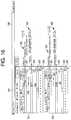
- FIGS. 7-18are diagrams of screenshots of a display of various wire sheets that may show radio buttons that can be clicked to provide configuration choices of inputs and outputs, and various circuits with connections to terminals of the cells.
- the present system and approachmay incorporate one or more processors, computers, controllers, user interfaces, wireless and/or wire connections, and/or the like, in an implementation described and/or shown herein.
- This descriptionmay provide one or more illustrative and specific examples or ways of implementing the present system and approach. There may be numerous other examples or ways of implementing the system and approach.
- the present systemmay consist of an “analog cell” that includes electronic circuits which can be configured with a processor, controller or microcomputer using programs designed to connect to a large range of different kinds of sensors and actuators, or other components.
- an “analog cell”that includes electronic circuits which can be configured with a processor, controller or microcomputer using programs designed to connect to a large range of different kinds of sensors and actuators, or other components.
- controllermay be used to refer to a controller, process, a computer, including an interface with a display of a screen and keyboard and a mouse, memory as needed, a mechanism for entering and executing programs, and so forth.
- a configuration for a particular sensor or actuatormay be performed by an OEM customer who sets up the controller for a particular purpose, or performed by an installer who has selected an appropriate or needed sensor or actuator.
- the present analog cellmay have only a few terminals which are to be configured for a wide range of components and purposes.
- a sensor or actuator which inherently needs several terminalsmay be implemented using most or all of the terminals; however, a cell may also support multiple input or output features or components if each of the features or components requires less than all of the terminals.
- components that need an entire cellmay be a bridge sensor, negative temperature coefficient (NTC) sensor, resistance temperature detector (RTD), powered potentiometer, actuator with feedback, and the like.
- Items that just need part of a cellmay consist of current input, current output, voltage input, voltage output, thermocouple input, voltage threshold detection, tachometer input, pulse width modulation (PWM) input, PWM output, a frequency/pulse generator, and so on.
- the systemmay differ in the breadth of coverage of sensor and actuator types. It may use a custom designed circuit to accomplish the coverage.
- the electronics of the present systemmay be included in a controller, and a program to configure the electronics can be provided as part of a user interface to the controller.
- Configuration optionsmay be selected by a designer or installer who is applying the controller, by making selections from typical dialog box items such as pop-up lists, checkboxes, and radio buttons in a screen on a display.
- An example of the configurationmay exist as a PC program described in conjunction with FIGS. 6-18 .
- the program and cellsmay have, for example, a particular application to components and circuits of heating, ventilation and air conditioning (HVAC) systems.
- HVACheating, ventilation and air conditioning
- the controllermay have an interface screen displaying three radio buttons at the top that may be clicked on to select which kind of module is being represented to incorporate an analog I/O module, a fuel air module, or a limit module.
- the fuel air modulemay contain two cells, the other two modules may each contain four cells although the program appears to show just two cells (the other cells may be identical).
- Each cellmay have a set of four terminals along with the circuit and configuration parameters that allow the cell to be operated in various ways.
- configuration choicesmay be represented by checkboxes.
- the most general form of a cellmay be shown by the analog I/O module.
- the modulemay provide very flexible combinations of non-safety analog inputs and outputs for “wire sheet” programmable logic (similar to PLC ladder logic).
- the fuel air and limit safety modulesmay also have fully functional analog cells, but when using the modules for their own safety I/O, they may restrict the configurations that are allowed. However, a feature for both of these safety modules is that any cell not necessarily needed for local safety use may be “donated” for more general use by the wire sheet logic. Thus, when a fuel air or limit is chosen in the demo, each of the two cells in those cases may have a radio button to either have the cell be used for the local safety purpose, or donated as a full-featured “wire sheet” cell. For fuel air, the local safety purpose may be called a VFD (variable frequency drive), which is a kind of variable speed motor).
- VFDvariable frequency drive
- the radio buttonsmay be used to set up an interface for an example component, and then one can try all of the features by using the checkboxes. Any combination that one can create in the program may be possible in the device, and vice versa. Any combination that one cannot create is not necessarily allowed.
- a location of a checkboxmay correspond to the terminal or terminals that carry the active signal or signals. In those cases, where an I/O function uses multiple terminals, this situation may be indicated by vertical lines.
- the lighter bars for T 1 , T 2 , and T 3may turn dark to show when a terminal has been used by a feature that has been selected.
- the dark colormay indicate that if one then clicks another checkbox within the dark bar, then a previous feature will be removed to give way to a new one.
- Onemay click to turn checkboxes off as well as on and, of course, trying that may make it more clear what those dark bars show.
- the darker barsare not necessarily used when demonstrating a Fuel Air or Limit cell, because the categories may have much simpler rules that can be shown as “1 input only” for a Limit cell, and “1 output, 1 input” for a Fuel Air VFD cell.
- An X on T 2may indicate that even though nothing is hooked up there, it cannot necessarily be used if that feature is selected.
- the NTC inputsmay be special, as shown, in that if a NTC sensor is used, then the only other thing that also might be on the same cell is a second NTC sensor.
- Two potentiometersmay also be special, as shown, in that they may share T 1 with each other but not with anything else.
- a row of icons to the left of T 4may indicate whether it is a signal ground/common terminal, or instead if it has a series resistance switched in (needed for NTC and RTD sensors) and generally cannot be used as a common terminal.
- the button “List All”may show a table of virtually all possibilities ( FIG. 6 ).
- FIG. 1is a diagram of a basic configuration of a cell system 10 .
- a controller 281may provide an interface, processing, including configuring from a program, for cell circuitry 282 to provide appropriate electrical values at a set of terminals 283 for connection by different components 284 where each component is connected to the same terminals 283 of a multitude of cell circuitries 282 that are the same, or is connected to the same cell circuitry 282 at different times.
- FIG. 1 ais a diagram showing a layout of an analog cell 11 .
- a power amplifier 12may have an input connected a digital to analog converter output 13 from a microcomputer 14 via a resistor 15 .
- the input of amplifier 12may also be connected to a timer output compare 16 of computer 14 .
- An output amplifier 12may go to an analog switch 17 that may have an input connected to a first switch control output 18 from computer 14 .
- Output 18may cause a switch 17 output 19 to be connected to output 18 or to a ground or voltage reference 21 via a resistor 22 .
- Output 19may go a first input of a dual 2:1 multiplexor 23 .
- Output 19may be connected to a second input of multiplexer 23 via a resistor 24 .
- connection to the second input of multiplexor 23may be connected to an input protection circuit 36 (e.g., diodes and spark gap) that is connected to a first terminal 31 of a strip 35 .
- a first multiplexor control signal 25may go from computer 14 to multiplexor 23 .
- a timer input capture 27 of computer 14may be connected via a resistor 28 and an input protection circuit 37 to a second terminal 32 of strip 35 .
- Input 27may also be connected via a resistor 29 to ground 21 .
- a connection between resistor 28 and protection circuit 37may be connected to a third input of multiplexor 23 .
- a second switch control output 42 from computer 14may go to a switch 44 .
- One side of switch 44may be connected via resistor 45 to ground 21
- another side of switch 44may be connected via a protection circuit 38 to a third terminal 33 of strip 35 .
- a third switch control output 43 of computer 14may go to a switch 46 .
- One side of switch 46may be connected via a resistor 47 to ground 21
- another side of switch 46may be connected to one side of protection circuit 38 that is connected to the other side of switch 44 .
- a common connection of the other side of switch 46 and the other side of switch 44 , and the one side of protection circuit 38may be connected to a fourth input of multiplexor 23 .
- a fourth terminal 34 of strip 35may be connected to ground 21 .
- a first output of multiplexor 23may go to four inputs of a dual 4:1 multiplexor 51 and a second output of multiplexor 23 may go to another four inputs of multiplexor 51 .
- a second multiplexor control signal 52may go from computer 14 to multiplexor 51 .
- a first output from multiplexor 51may go to an inverting input of an instrumentation amplifier 54 .
- a second output from multiplexor 51may go to a non-inverting input of amplifier 54 .
- An output of amplifier 54may be an analog to digital converter input 55 to computer 14 .
- a gain resistor 56 of amplifier 54may be a digital potentiometer adjustable by an instrumentation amplifier gain control output 57 from computer 14 .
- An offset resistor 58having one end connected to a positive voltage source and another end connected to ground 21 may be a digital potentiometer adjustable by an instrumentation amplifier offset control output 59 from computer 14 .
- circuits of FIGS. 1-3are merely examples of the cell. Connections and components of the circuit may be varied and/or changed as desired.
- FIG. 2is another type of diagram of an analog cell 61 .
- a voltage signal 65 of a digital to analog converter of processor 62may go through a resistor 63 to a non-inverting input of a power amplifier 64 .
- An F out signal 66 from processor 62may be a switch control signal to switches 67 and 68 .
- One end of switch 67may be connected to the non-inverting input of amplifier 64 and another end of switch 67 may be connected to a ground or reference voltage 69 .
- Control signal 66may open and close switches 67 and 68 . For instance, when switches 67 and 68 are closed, then the non-inverting input of amplifier 64 may be grounded and the inverting input of amplifier 64 may be connected to a bias voltage.
- a limit input and a por/disable input with a control signal inputmay be connected to amplifier 64 .
- An output of amplifier 64may be connected to one end of a resistor 71 and to a first input of a voltage gain mechanism 72 . Another end of resistor 71 may be connected to a second input of mechanism 72 , a cathode of a zener diode 73 , and one end of a resistor 74 . Another end of resistor 74 may be connected to a first terminal 81 of a terminal strip 85 . An anode of diode 73 may be connected to ground 69 . An output 87 of mechanism 72 may go as a VIN 1 to a circuit 100 .
- a resistor 93may have one end connected to terminal 81 and another end connected to a cathode of a diode 94 and to an input of a gain mechanism 95 .
- An output 86 of mechanism 95may go as a VIN 0 input to circuit 100 , and go to inverting input of amplifier 69 .
- a second terminal 82 of strip 85may be connected to one end of a resistor 101 .
- Another end of resistor 101may be connected to a cathode of a diode 102 and an anode of a diode 103 .
- An anode of diode 102may be connected to ground 69 and a cathode of diode 103 may be connected to a voltage 104 .
- the other end of resistor 101may also be connected to an input of an amplifier 105 .
- An output of amplifier 105may go to an input of a comparator 106 .
- Another input of amplifier 106may be connected to a reference voltage.
- An output of comparator 106may be a PWM input 107 to processor 62 .
- the output of amplifier 105may be connected to one end of a resistor 108 .
- Another end of resistor 108may be connected to a selectable gain mechanism 109 and to one end of a capacitor 111 .
- An output 89may go as a VIN 3 to circuit 100 .
- Another end of capacitor 110may be connected to one side of a switch 112 and to one end of a capacitor 113 .
- Another end of switch 117may be connected to ground 69 .
- Switch 112may have a control input.
- a third terminal 83 of strip 85may be connected to one end of a resistor 114 .
- Terminal 83may be connected to a cathode of a diode 115 , and to one end of a resistor 116 .
- Another end of resistor 116may be connected to one end of a switch 117 .
- Another end of switch 117may be connected to ground 69 .
- Switch 117may have a control input.
- An anode of diode 115may be connected to a current source of circuit 100 .
- resistor 114may be connected to an input of an amplifier 118 .
- the other end of resistor 114may be connected to a cathode of a diode 119 and an anode of a diode 121 .
- An anode of diode 119may be connected to a ground 69 .
- a cathode of diode 121may be connected to a voltage 122 .
- the other end of resistor 114may be connected to one end of a resistor 123 .
- Another end of resistor 123may be connected to one end of a switch 124 .
- Another end of switch 124may be connected to ground 69 .
- Switch 124may have a control input.
- An output of amplifier 118may be connected to one end of a resistor 125 . Another end of resistor 125 may be connected to another end of capacitor 113 , and to an input of a selectable gain mechanism 126 . An output 90 of VIN 4 from mechanism 126 may go to circuit 100 .
- a gain mechanism 127may have a voltage input and a cell ID output 91 as a VIN 5 to circuit 100 .
- a temperature sensitive resistor 129 adjacent to terminals 83 and 84may go as an output from resistor 129 as VIN 2 to circuit 100 .
- a fourth terminal 84 of strip 85may be connected to ground 69 via a resistor 131 .
- Terminal 84may be connected to one end of a resistor 132 and one end of a resistor 133 .
- Another end of resistor 132may be connected to a cathode of a diode 134 and to an anode of a diode 135 .
- An anode of diode 134may be connected to ground 69 .
- a cathode of diode 135may be connected to a voltage 136 .
- the other end of resistor 132may be connected to one end of a switch 137 .
- Switch 137may have another end connected to ground 69 .
- Switch 137may have a control input.
- resistor 133may be connected to a cathode of a diode 138 and to an anode of a diode 139 .
- An anode of diode 138may be connected to ground 69 .
- a cathode of diode 139may be connected to a voltage 141 .
- the other end of resistor 133may be an input 142 as a VREF 2 to circuit 100 .
- a voltage reference mechanism 143may have an output 144 as a VREF 1 to circuit 100 .
- One or more control signals 145may be provided by circuit 100 for various control inputs for switches, selectable gain mechanisms, and so forth in cell 61 .
- Processor 62may provide various voltages at output 147 for components as desired of cell 61 .
- Outputs 148 and 149may provide signals or current from processor 62 to circuit 100 .
- FIG. 3 a and FIG. 3 bare diagrams that reveal a schematic of an example cell and associated circuitry. Other designs may be used or a design of the present schematic may be modified for a particular application. Common connections and components of FIGS. 3 a and 3 b for the schematic may be designated by numerals 161 - 179 .
- the terminals T 1 , T 2 , T 3 and T 4 of the cellare indicated by numerals 181 , 182 , 183 and 184 , respectively.
- FIG. 4is a diagram of a cell module 200 .
- Each cellmay have terminals 211 , 212 , 213 and 214 .
- Each one of pairs 209 and 210may provide for NTC, RTD, TC, mA or V sensors.
- FIG. 5is a diagram of a cell module 220 of cells 215 , 216 , 217 and 218 .
- Each cellmay have terminals 211 , 212 , 213 and 214 .
- the cells 215 - 218may provide for eight analog I/O circuits (e.g., four analog blocks).
- FIG. 6is a diagram of screen shot 250 of a display for applications of interface for various circuits using a common set of terminals of the present universal cell.
- Analog block wire sheets 251 and 252are shown in layout 254 .
- Various circuits and terminals of a cell blockare shown in a list 253 .
- a maximum number of circuitsmay be indicated for four cells as revealed on the right column of list 253 .
- FIG. 7-18are diagrams of example circuits that may be interfaced with some or all four terminals T 1 -T 4 which can have numeral designations of 261 , 262 , 263 and 264 .
- terminals T 1 -T 4which can have numeral designations of 261 , 262 , 263 and 264 .
- At the top of layout 254 containing wire sheets 251 and 252may be a choice of selections of “Analog I/O”, “Fuel Air” and “Limit”.
- FIG. 7is a diagram of wire sheets 251 and 252 with buttons 266 , 267 and 268 checked for a Bridge circuit 269 and two NTC circuits 271 .
- FIG. 8is a diagram of the wire sheets with buttons 272 , 273 and 274 checked for Potentiometers 275 and 276 .
- FIG. 9is a diagram of the wire sheets with buttons 277 , 278 , 279 and 280 checked for a Potentiometer 281 , Voltage Threshold 282 , Pulse Width Modulation 283 and RTD 284 , respectively.
- FIG. 10is a diagram of the wire sheets with buttons 286 and 287 checked for a Four-Wire RTD 288 and a Thermocouple 289 .
- FIG. 11is a diagram of the wire sheets with buttons 291 , 292 , 293 , 294 , 295 and 296 checked for a first Voltage Threshold 297 , a second Voltage Threshold 298 , a third Voltage Threshold 299 , a Voltage Out 300 , a PWM In 301 , and a Voltage In 302 .
- FIG. 12is a diagram of the wire sheets with buttons 304 , 305 and 306 checked for a PWM In 307 , Current In 308 and Tachometer In 309 .
- FIG. 11is a diagram of the wire sheets with buttons 291 , 292 , 293 , 294 , 295 and 296 checked for a first Voltage Threshold 297 , a second Voltage Threshold 298 , a third Voltage Threshold 299 , a Voltage Out 300 , a PWM In 301 , and a Voltage In 302 .
- FIG. 13is a diagram of the wire sheets with buttons 311 , 312 , 313 , 314 , 315 and 316 checked for a Voltage Out 317 , PWM In 318 , Current In 319 , Current Out 320 , Tachometer In 321 and Voltage In 322 .
- FIG. 14is a diagram of the wire sheets with buttons 324 , 325 , 326 , 327 , 328 and 329 checked for a Current Out 330 , PWM In 331 , Voltage Threshold 332 , Pulse Width Modulation 333 , Tachometer In 334 and Voltage In 335 , respectively.
- FIG. 15is a diagram of wire sheets with buttons 337 , 338 , 339 , 340 and 341 checked for a Pulse Width Modulation 342 , Four-Wire RTD 343 , Voltage Out 344 , PWM In 345 and Voltage In 346 .
- FIG. 16is a diagram with “Fuel Air” selected above wire sheet 251 .
- Buttons 348 , 349 , 350 and 351 of the wire sheetsmay be checked for a Voltage Out 352 , PWM In 353 , Current Out 354 and Tachometer In 355 , respectively.
- FIG. 17is a diagram with “Limit” selected above wire sheet 251 .
- Buttons 357 and 358may be checked for a Thermocouple 359 and Four-Wire RTD 360 , respectively.
- FIG. 18is a diagram of the wire sheets with buttons 361 and 362 that may be checked for a Three-Wire Dual NTC 363 . Both cells for wire sheets 251 and 252 may cooperate to periodically test for common-mode failures such as increased resistance in a common mode.
- a universal interface systemmay incorporate a cell, and a computer connected to the cell.
- the cellmay incorporate one or more terminals.
- the cellmay provide at the one or more terminals inputs and outputs that are configured to be compatible for a set of electrical components of a heating, ventilation and air conditioning (HVAC) system.
- HVACheating, ventilation and air conditioning
- the one or more terminalsmay provide inputs and outputs that are reconfigured to be compatible for a different set of electrical components of the HVAC system.
- Inputs and outputs at the one or more terminalsmay be configured at the cell incorporating signals from the computer according to a program.
- the computermay provide a display of a screen showing items to click on for providing appropriate values at the one or more terminals for connection by the one or more components of a set of electrical components.
- the sets of one or more electrical componentsmay incorporate one or more sensors and/or actuators.
- the one or more sensors or actuatorsmay be selected from a group incorporating bridge sensors, NTC sensors, RTD sensors, powered potentiometers, and actuators with feedback.
- Inputs and outputs at one or more terminalsmay be selected from a group incorporating current inputs, current outputs, voltage inputs, voltage outputs, thermocouple inputs, voltage threshold detections, tachometer inputs, PWM inputs, PWM outputs, and frequency/pulse generator outputs.
- the computermay configure a cell for a particular sensor or actuator to be connected to the one or more terminals according to the program.
- a cellmay support two or more sensors or actuators at one time.
- a usermay select from a list of configurations on a screen for use or a making.
- One or more terminals of the cellmay provide analog signal inputs and outputs to an appropriate connection of the sensors and actuators.
- the one or more terminalsmay have input signals and output signals with magnitudes less than 50 volts.
- the systemmay further incorporate additional cells that are numbered in groups of two or more cells.
- Each of the cellsmay have a set of four terminals.
- Each set of four terminalsmay provide an interface for up to a certain number of, such as three, analog I/O circuits to support a certain number of, such as three, sensors and/or actuators at one time.
- An approach for providing interfaces for analog mechanismsmay incorporate obtaining a cell having circuitry with a predetermined number of terminals, configuring the circuitry for obtaining one or more interfaces at the predetermined number of terminals for a first kind of one or more sensors and/or actuators, reconfiguring the circuitry according to a program for obtaining another one or more interfaces at the predetermined number of terminals for a second kind of one or more sensors and/or actuators, and connecting a processor to the cell that configures or reconfigures the circuitry for obtaining the one or more interfaces appropriate for a kind of the one or more sensors and/or actuators.
- the approachmay further incorporate determining a number for the predetermined number of terminals by setting the number where there are two or less terminals remaining when the one or more sensors and/or actuators are connected to the predetermined number of terminals.
- the one or more sensors and/or actuatorsmay be selected from a group incorporating bridge sensors, NTC sensors, RTD sensors, powered potentiometers, and actuators with feedback.
- One or more inputs and outputs at one or more terminalsmay be selectable for one or more items from a group incorporating current inputs, current outputs, voltage inputs, voltage outputs, thermocouple inputs, voltage threshold detection inputs, tachometer inputs, PWM inputs, PWM outputs, and frequency/pulse generator outputs.
- the approachmay further incorporate adding one or more cells.
- Each cellmay have circuitry connected to a predetermined number of terminals.
- the approachmay further incorporate configuring the circuitry of a cell for obtaining one or more interfaces at the predetermined number of or less terminals for a first kind of electrical components, reconfiguring the circuitry of the cell for obtaining another one or more interfaces at the predetermined number of or less terminals for a second kind of electrical components, and connecting a processor to the cell that configures and reconfigures the circuitry according to a program for obtaining the one or more interfaces at the predetermined number of or less terminals.
- the approachmay further incorporate predetermining a number of terminals by setting the number where there are two or less terminals remaining when the one or more electrical components are connected to the predetermined number of terminals.
- the one or more electrical componentsmay be selected from a group incorporating bridge sensors, NTC sensors, RTD sensors, powered potentiometers, and actuators with feedback.
- One or more inputs and outputs at the predetermined number of terminalsmay be selected from a group incorporating current inputs, current outputs, voltage inputs, voltage outputs, thermocouple inputs, voltage threshold detection inputs, tachometer inputs, PWM inputs, PWM outputs, and frequency/pulse generator outputs.
- An analog interface block mechanismmay incorporate an interface block having configurable inputs and outputs, and a processor connected to the interface block.
- the interface blockmay incorporate circuitry that is affected by a program executed by the processor to result in configured inputs and outputs of the interface block.
- the inputs and outputsmay be configured for establishing compatibility with a first set of one or more sensors and/or actuators of an HVAC system, that are connected to the inputs and outputs of the interface block.
- the inputs and outputsmay be reconfigured for establishing compatibility with a second set of one or more sensors and/or actuators of an HVAC system, that are connected to the inputs and outputs of the interface block.
- the mechanismmay further incorporate a display for showing a dialog box having items that are selectable for configuring an input or output of the interface block for a compatible connection with a sensor or actuator.
- the mechanismmay further incorporate one or more additional interface blocks like the first interface block, connected to the processor.
- Each of the additional interface blocksmay incorporate configurable inputs and outputs.
- Each of the additional interface blocksmay incorporate circuitry that is affected by a program executed by the processor to result in configured inputs and outputs of the interface block.
- the inputs and outputsmay be configured for establishing compatibility with a third set of one or more sensors and/or actuators that are connected to the inputs and outputs of the interface block.
- the inputs and outputsmay be reconfigured for establishing compatibility with a fourth set of one or more sensors and/or actuators that are connected to the inputs and outputs of the interface block.
- Each interface blockmay incorporate an N number of terminals.
- One or more terminals of the N number of terminals of an interface blockmay be configured to be an input/output for a selected sensor or actuator.
- the one or more terminals of the N number of terminals of the same interface blockmay be reconfigured to be an input/output for another selected sensor or actuator.
- the N number of terminalsmay be kept at a minimum.
Landscapes
- Physics & Mathematics (AREA)
- General Physics & Mathematics (AREA)
- Engineering & Computer Science (AREA)
- Automation & Control Theory (AREA)
- Air Conditioning Control Device (AREA)
- Arrangements For Transmission Of Measured Signals (AREA)
Abstract
Description
Claims (12)
Priority Applications (1)
| Application Number | Priority Date | Filing Date | Title |
|---|---|---|---|
| US14/869,808US10678204B2 (en) | 2014-09-30 | 2015-09-29 | Universal analog cell for connecting the inputs and outputs of devices |
Applications Claiming Priority (2)
| Application Number | Priority Date | Filing Date | Title |
|---|---|---|---|
| US201462057684P | 2014-09-30 | 2014-09-30 | |
| US14/869,808US10678204B2 (en) | 2014-09-30 | 2015-09-29 | Universal analog cell for connecting the inputs and outputs of devices |
Publications (2)
| Publication Number | Publication Date |
|---|---|
| US20160123624A1 US20160123624A1 (en) | 2016-05-05 |
| US10678204B2true US10678204B2 (en) | 2020-06-09 |
Family
ID=55852277
Family Applications (1)
| Application Number | Title | Priority Date | Filing Date |
|---|---|---|---|
| US14/869,808Expired - Fee RelatedUS10678204B2 (en) | 2014-09-30 | 2015-09-29 | Universal analog cell for connecting the inputs and outputs of devices |
Country Status (1)
| Country | Link |
|---|---|
| US (1) | US10678204B2 (en) |
Families Citing this family (6)
| Publication number | Priority date | Publication date | Assignee | Title |
|---|---|---|---|---|
| US10288286B2 (en) | 2014-09-30 | 2019-05-14 | Honeywell International Inc. | Modular flame amplifier system with remote sensing |
| US10402358B2 (en) | 2014-09-30 | 2019-09-03 | Honeywell International Inc. | Module auto addressing in platform bus |
| US10678204B2 (en) | 2014-09-30 | 2020-06-09 | Honeywell International Inc. | Universal analog cell for connecting the inputs and outputs of devices |
| US10042375B2 (en) | 2014-09-30 | 2018-08-07 | Honeywell International Inc. | Universal opto-coupled voltage system |
| US10473329B2 (en) | 2017-12-22 | 2019-11-12 | Honeywell International Inc. | Flame sense circuit with variable bias |
| US10935237B2 (en) | 2018-12-28 | 2021-03-02 | Honeywell International Inc. | Leakage detection in a flame sense circuit |
Citations (143)
| Publication number | Priority date | Publication date | Assignee | Title |
|---|---|---|---|---|
| US3425780A (en) | 1966-09-26 | 1969-02-04 | Liberty Combustion Corp | Fluid fuel igniter control system |
| US3520645A (en) | 1968-05-24 | 1970-07-14 | Maytag Co | Control system for a fuel burner |
| US3649156A (en) | 1969-11-13 | 1972-03-14 | Eaton Yale & Towne | Fluid fuel burner control system |
| US3681001A (en) | 1970-05-15 | 1972-08-01 | Liberty Combustion Corp | Fluid fuel igniter control system |
| US3836857A (en) | 1972-05-12 | 1974-09-17 | Hitachi Ltd | Flame detector |
| US3909816A (en) | 1974-04-29 | 1975-09-30 | Lloyd L Teeters | Flame and carbon monoxide sensor and alarm circuit |
| US4157506A (en) | 1977-12-01 | 1979-06-05 | Combustion Engineering, Inc. | Flame detector |
| US4221557A (en) | 1978-06-12 | 1980-09-09 | Gas Research Institute | Apparatus for detecting the occurrence of inadequate levels of combustion air at a flame |
| US4242079A (en) | 1978-12-07 | 1980-12-30 | Johnson Controls, Inc. | Fuel ignition control system |
| US4269589A (en) | 1978-12-04 | 1981-05-26 | Johnson Controls, Inc. | Solid state ignition control |
| US4280184A (en) | 1979-06-26 | 1981-07-21 | Electronic Corporation Of America | Burner flame detection |
| US4303385A (en) | 1979-06-11 | 1981-12-01 | Johnson Controls, Inc. | Direct ignition system for gas appliance with DC power source |
| US4370557A (en) | 1980-08-27 | 1983-01-25 | Honeywell Inc. | Dual detector flame sensor |
| US4450499A (en) | 1981-12-21 | 1984-05-22 | Sorelle Roland R | Flare ignition system |
| US4457692A (en) | 1983-08-22 | 1984-07-03 | Honeywell Inc. | Dual firing rate flame sensing system |
| US4483672A (en) | 1983-01-19 | 1984-11-20 | Essex Group, Inc. | Gas burner control system |
| US4519771A (en) | 1982-04-02 | 1985-05-28 | U.S. Philips Corporation | Flame detection system with isolation between burner and electronic control device |
| US4521825A (en) | 1982-10-20 | 1985-06-04 | Technical Components Pty. Ltd. | Gas ignition circuits |
| US4527247A (en) | 1981-07-31 | 1985-07-02 | Ibg International, Inc. | Environmental control system |
| US4555800A (en) | 1982-09-03 | 1985-11-26 | Hitachi, Ltd. | Combustion state diagnostic method |
| US4622005A (en) | 1984-10-27 | 1986-11-11 | Rinnai Corporation | Ignition and flame monitoring device |
| US4626193A (en) | 1985-08-02 | 1986-12-02 | Itt Corporation | Direct spark ignition system |
| US4641108A (en) | 1985-10-16 | 1987-02-03 | Raytheon Company | Configurable analog integrated circuit |
| US4655705A (en) | 1986-02-28 | 1987-04-07 | Shute Alan B | Power gas burner for wood stove |
| US4672324A (en) | 1984-04-12 | 1987-06-09 | U.S. Philips Corporation | Flame protection circuit |
| US4695246A (en) | 1984-08-30 | 1987-09-22 | Lennox Industries, Inc. | Ignition control system for a gas appliance |
| US4701878A (en) | 1983-12-28 | 1987-10-20 | Siemens Aktiengesellschaft | Apparatus for assigning addresses to pluggable modules based on contact configuration |
| US4709155A (en) | 1984-11-22 | 1987-11-24 | Babcock-Hitachi Kabushiki Kaisha | Flame detector for use with a burner |
| EP0276937A1 (en) | 1987-01-29 | 1988-08-03 | British Gas plc | Safety monitor |
| US4777607A (en)* | 1984-05-17 | 1988-10-11 | Spie Batignolles | Interface device for control and monitoring of distribution panelboards |
| US4830601A (en) | 1985-02-12 | 1989-05-16 | Dahlander Paer N O | Method for the control of a burner equipped with an injector nozzle and an arrangement for executing the method |
| US4842510A (en) | 1987-09-10 | 1989-06-27 | Hamilton Standard Controls, Inc. | Integrated furnace control having ignition and pressure switch diagnostics |
| US4843084A (en) | 1987-02-12 | 1989-06-27 | Parker Electronics, Inc. | Thermostat control system |
| EP0325356A2 (en) | 1988-01-21 | 1989-07-26 | Honeywell Inc. | Multiple fuel burner control system |
| US4872828A (en) | 1987-09-10 | 1989-10-10 | Hamilton Standard Controls, Inc. | Integrated furnace control and control self test |
| US4904986A (en) | 1989-01-04 | 1990-02-27 | Honeywell Inc. | IR flame amplifier |
| US4949355A (en) | 1989-01-23 | 1990-08-14 | Rockwell International Corporation | Test access system for a digital loop carrier system |
| US4955806A (en) | 1987-09-10 | 1990-09-11 | Hamilton Standard Controls, Inc. | Integrated furnace control having ignition switch diagnostics |
| WO1991002300A1 (en) | 1989-07-28 | 1991-02-21 | Johnson Service Company | Universal analog input |
| US5026270A (en) | 1990-08-17 | 1991-06-25 | Honeywell Inc. | Microcontroller and system for controlling trial times in a furnace system |
| US5026272A (en) | 1988-06-03 | 1991-06-25 | Yamatake-Honeywell Co., Ltd. | Combustion control device |
| US5037291A (en) | 1990-07-25 | 1991-08-06 | Carrier Corporation | Method and apparatus for optimizing fuel-to-air ratio in the combustible gas supply of a radiant burner |
| US5073769A (en) | 1990-10-31 | 1991-12-17 | Honeywell Inc. | Flame detector using a discrete fourier transform to process amplitude samples from a flame signal |
| US5077550A (en) | 1990-09-19 | 1991-12-31 | Allen-Bradley Company, Inc. | Burner flame sensing system and method |
| US5112117A (en) | 1990-02-13 | 1992-05-12 | Robert Bosch Gmbh | Vehicle brake system with anti-skid apparatus |
| US5126721A (en) | 1990-10-23 | 1992-06-30 | The United States Of America As Represented By The United States Department Of Energy | Flame quality monitor system for fixed firing rate oil burners |
| US5158477A (en) | 1991-11-15 | 1992-10-27 | The United States Of America As Represented By The Secretary Of The Army | Battery connector and method |
| US5175439A (en) | 1987-12-21 | 1992-12-29 | Robert Bosch Gmbh | Power supply circuit for motor vehicles |
| US5222888A (en) | 1991-08-21 | 1993-06-29 | Emerson Electric Co. | Advanced proof-of-rotation switch |
| US5236328A (en) | 1992-09-21 | 1993-08-17 | Honeywell Inc. | Optical flame detector performance tester |
| US5255179A (en) | 1990-07-23 | 1993-10-19 | Zekan Boze N | Switched mode power supply for single-phase boost commercial AC users in the range of 1 kw to 10 kw |
| US5276630A (en) | 1990-07-23 | 1994-01-04 | American Standard Inc. | Self configuring controller |
| US5280802A (en) | 1992-11-16 | 1994-01-25 | Comuzie Jr Franklin J | Gas appliance detection apparatus |
| US5300836A (en) | 1991-06-28 | 1994-04-05 | Samsung Electronics Co., Ltd. | Flame rod structure, and a compensating circuit and control method thereof |
| US5347982A (en) | 1992-12-21 | 1994-09-20 | Canadian Heating Products Inc. | Flame monitor safeguard system |
| US5365223A (en) | 1991-10-28 | 1994-11-15 | Honeywell Inc. | Fail-safe condition sensing circuit |
| US5391074A (en) | 1994-01-31 | 1995-02-21 | Meeker; John | Atmospheric gas burner and control system |
| US5424554A (en) | 1994-03-22 | 1995-06-13 | Energy Kenitics, Inc. | Oil-burner, flame-intensity, monitoring system and method of operation with an out of range signal discriminator |
| US5446677A (en) | 1994-04-28 | 1995-08-29 | Johnson Service Company | Diagnostic system for use in an environment control network |
| US5472336A (en) | 1993-05-28 | 1995-12-05 | Honeywell Inc. | Flame rectification sensor employing pulsed excitation |
| US5506569A (en) | 1994-05-31 | 1996-04-09 | Texas Instruments Incorporated | Self-diagnostic flame rectification sensing circuit and method therefor |
| US5567143A (en) | 1995-07-07 | 1996-10-22 | Servidio; Patrick F. | Flue draft malfunction detector and shut-off control for oil burner furnaces |
| US5599180A (en) | 1993-07-23 | 1997-02-04 | Beru Ruprecht Gmbh & Co. Kg | Circuit arrangement for flame detection |
| WO1997018417A1 (en) | 1995-11-13 | 1997-05-22 | Gas Research Institute, Inc. | Flame ionization control apparatus and method |
| US5682329A (en) | 1994-07-22 | 1997-10-28 | Johnson Service Company | On-line monitoring of controllers in an environment control network |
| US5722823A (en) | 1994-11-18 | 1998-03-03 | Hodgkiss; Neil John | Gas ignition devices |
| US5748466A (en)* | 1995-09-08 | 1998-05-05 | L. R. Nelson | Adaptable control system for a variable number of switches |
| US5797358A (en) | 1996-07-08 | 1998-08-25 | Aos Holding Company | Control system for a water heater |
| EP0967440A2 (en) | 1998-06-25 | 1999-12-29 | L'air Liquide, Societe Anonyme Pour L'etude Et L'exploitation Des Procedes Georges Claude | Optical monitoring and control system for oil combustion |
| US6060719A (en) | 1997-06-24 | 2000-05-09 | Gas Research Institute | Fail safe gas furnace optical flame sensor using a transconductance amplifier and low photodiode current |
| US6071114A (en) | 1996-06-19 | 2000-06-06 | Meggitt Avionics, Inc. | Method and apparatus for characterizing a combustion flame |
| US6084518A (en) | 1999-06-21 | 2000-07-04 | Johnson Controls Technology Company | Balanced charge flame characterization system and method |
| US6127742A (en)* | 1996-07-16 | 2000-10-03 | Schneider Electric Sa | Draw-out electrical switchgear apparatus |
| US6172432B1 (en) | 1999-06-18 | 2001-01-09 | Gen-Tran Corporation | Automatic transfer switch |
| US6222719B1 (en) | 1999-07-15 | 2001-04-24 | Andrew S. Kadah | Ignition boost and rectification flame detection circuit |
| US6261086B1 (en) | 2000-05-05 | 2001-07-17 | Forney Corporation | Flame detector based on real-time high-order statistics |
| US6299433B1 (en) | 1999-11-05 | 2001-10-09 | Gas Research Institute | Burner control |
| EP1148298A1 (en) | 2000-04-21 | 2001-10-24 | CSEM Centre Suisse d'Electronique et de Microtechnique SA | Control method of a burner |
| US6346712B1 (en) | 1998-04-24 | 2002-02-12 | Electrowatt Technology Innovation Ag | Flame detector |
| US6349156B1 (en) | 1999-10-28 | 2002-02-19 | Agere Systems Guardian Corp. | Semiconductor etalon device, optical control system and method |
| US6356827B1 (en) | 2000-05-30 | 2002-03-12 | Delphi Technologies, Inc. | Auxiliary control with diagnostic capability |
| US6381503B1 (en) | 1995-10-13 | 2002-04-30 | Belanger, Inc. | Interface circuit for processor controlled system and vehicle laundry system utilizing such interface circuit |
| US6385510B1 (en) | 1997-12-03 | 2002-05-07 | Klaus D. Hoog | HVAC remote monitoring system |
| US20020059467A1 (en)* | 2000-09-20 | 2002-05-16 | Lockheed Martin Corporation | Object oriented framework architecture for sensing and/or control environments |
| US20020099474A1 (en) | 1997-12-18 | 2002-07-25 | Khesin Mark J. | Combustion diagnostics method and system |
| US6457692B1 (en) | 2000-10-16 | 2002-10-01 | Northwest Refrigeration Contractors, Inc. | Hanger bracket for installing and supporting suspended equipment |
| US6474979B1 (en) | 2000-08-29 | 2002-11-05 | Emerson Electric Co. | Device and method for triggering a gas furnace ignitor |
| US6486486B1 (en) | 1998-09-10 | 2002-11-26 | Siemens Building Technologies Ag | Flame monitoring system |
| US20020193890A1 (en)* | 2000-12-15 | 2002-12-19 | Pouchak Michael A. | Fault-tolerant multi-node stage sequencer and method for energy systems |
| US6509838B1 (en) | 2000-02-08 | 2003-01-21 | Peter P. Payne | Constant current flame ionization circuit |
| US6552865B2 (en) | 2001-05-25 | 2003-04-22 | Infineon Technologies Ag | Diagnostic system for a read/write channel in a disk drive |
| US20030143503A1 (en) | 2002-01-28 | 2003-07-31 | Wild Gary G. | Industrial flame sensor communication system |
| US20030222982A1 (en) | 2002-03-28 | 2003-12-04 | Hamdan Majil M. | Integrated video/data information system and method for application to commercial vehicles to enhance driver awareness |
| US6676404B2 (en) | 2000-05-12 | 2004-01-13 | Siemens Building Technologies Ag | Measuring device for a flame |
| US6743010B2 (en) | 2002-02-19 | 2004-06-01 | Gas Electronics, Inc. | Relighter control system |
| US6782345B1 (en) | 2000-10-03 | 2004-08-24 | Xerox Corporation | Systems and methods for diagnosing electronic systems |
| US6794771B2 (en) | 2002-06-20 | 2004-09-21 | Ranco Incorporated Of Delaware | Fault-tolerant multi-point flame sense circuit |
| US20040209209A1 (en) | 2002-11-04 | 2004-10-21 | Chodacki Thomas A. | System, apparatus and method for controlling ignition including re-ignition of gas and gas fired appliances using same |
| US20050086341A1 (en) | 2000-06-15 | 2005-04-21 | Enga David A. | Utility monitoring and control systems |
| US6912671B2 (en) | 2001-05-07 | 2005-06-28 | Bisher-Rosemount Systems, Inc | Wiring fault detection, diagnosis and reporting for process control systems |
| US6917888B2 (en) | 2002-05-06 | 2005-07-12 | Arkados, Inc. | Method and system for power line network fault detection and quality monitoring |
| US6923640B2 (en) | 2001-09-28 | 2005-08-02 | General Electric Company | Flame burner ignition system |
| WO2005098954A1 (en) | 2004-04-02 | 2005-10-20 | Triad Semiconductor, Inc. | Via configurable architecture for customization of analog circuitry in a semiconductor device |
| US7076311B2 (en) | 2002-07-09 | 2006-07-11 | Rockwell Automation Technologies, Inc. | Configurable safety system for implementation on industrial system and method of implementing same |
| US20060155900A1 (en)* | 2001-02-14 | 2006-07-13 | Paul Sagues | System for programmed control of signal input and output to and from cable conductors |
| US7088137B2 (en) | 2004-05-04 | 2006-08-08 | International Business Machines Corporation | System, method and program product for extending range of a bidirectional data communication bus |
| US7088253B2 (en) | 2004-02-10 | 2006-08-08 | Protection Controls, Inc. | Flame detector, method and fuel valve control |
| US20060257805A1 (en) | 2005-05-12 | 2006-11-16 | Honeywell International Inc. | Adaptive spark ignition and flame sensing signal generation system |
| US7202794B2 (en) | 2004-07-20 | 2007-04-10 | General Monitors, Inc. | Flame detection system |
| US7241135B2 (en) | 2004-11-18 | 2007-07-10 | Honeywell International Inc. | Feedback control for modulating gas burner |
| US7242116B2 (en) | 2003-02-12 | 2007-07-10 | Japan Control Engineering Co., Ltd. | Safety controller |
| US20070159978A1 (en) | 2006-01-10 | 2007-07-12 | Honeywell International Inc. | Remote communications diagnostics using analog data analysis |
| US7255285B2 (en) | 2003-10-31 | 2007-08-14 | Honeywell International Inc. | Blocked flue detection methods and systems |
| US20070188971A1 (en) | 2006-02-15 | 2007-08-16 | Honeywell International Inc. | Circuit diagnostics from flame sensing ac component |
| US7274973B2 (en) | 2003-12-08 | 2007-09-25 | Invisible Service Technicians, Llc | HVAC/R monitoring apparatus and method |
| US7289032B2 (en) | 2005-02-24 | 2007-10-30 | Alstom Technology Ltd | Intelligent flame scanner |
| US20080010049A1 (en)* | 2006-06-29 | 2008-01-10 | Honeywell International Inc. | Graphical language compiler system |
| US7327269B2 (en) | 2003-05-19 | 2008-02-05 | International Thermal Investments Ltd. | Flame sensor for a burner |
| WO2008144308A1 (en) | 2007-05-16 | 2008-11-27 | Square D Company | Modular power monitoring system |
| US20090009344A1 (en) | 2007-07-03 | 2009-01-08 | Honeywell International Inc. | Flame rod drive signal generator and system |
| US20090056649A1 (en) | 2007-08-31 | 2009-03-05 | Mackenzie Bruce G | Boiler Protection Apparatus and Method |
| US20090136883A1 (en) | 2007-07-03 | 2009-05-28 | Honeywell International Inc. | Low cost high speed spark voltage and flame drive signal generator |
| US7617691B2 (en) | 2000-03-14 | 2009-11-17 | Hussmann Corporation | Refrigeration system and method of operating the same |
| US20100013644A1 (en) | 2005-05-12 | 2010-01-21 | Honeywell International Inc. | Flame sensing voltage dependent on application |
| US7728736B2 (en) | 2007-04-27 | 2010-06-01 | Honeywell International Inc. | Combustion instability detection |
| US20100185857A1 (en)* | 2009-01-21 | 2010-07-22 | Lee Allen Neitzel | Removable security modules and related methods |
| US7764182B2 (en) | 2005-05-12 | 2010-07-27 | Honeywell International Inc. | Flame sensing system |
| US7768410B2 (en) | 2005-05-12 | 2010-08-03 | Honeywell International Inc. | Leakage detection and compensation system |
| US7800508B2 (en) | 2005-05-12 | 2010-09-21 | Honeywell International Inc. | Dynamic DC biasing and leakage compensation |
| US7822896B1 (en)* | 2001-02-14 | 2010-10-26 | Berkeley Process Control, Inc. | Electronically configurable connector module |
| US20110207064A1 (en) | 2009-11-23 | 2011-08-25 | Hamworthy Combustion Engineering Limited | Monitoring Flare Stack Pilot Burners |
| EP2388960A1 (en) | 2010-05-18 | 2011-11-23 | O2 Micro, Inc. | Intelligent bus address self-configuration in a multi-module system |
| US8299559B2 (en) | 2003-03-18 | 2012-10-30 | Hagop Nazarian | Re-configurable mixed-mode integrated circuit architecture |
| US8390324B2 (en) | 2010-09-20 | 2013-03-05 | Honeywell International Inc. | Universal functionality module |
| US8601291B2 (en) | 1996-07-23 | 2013-12-03 | Server Technology, Inc. | Power management device with communications capability and method of use |
| US8656065B1 (en)* | 2013-01-29 | 2014-02-18 | Honeywell International Inc. | Method and apparatus for automatically selecting a plurality of modes for programmable interface circuit by coupling field devices to process controllers |
| US8769158B2 (en) | 2011-07-08 | 2014-07-01 | Rockwell Automation Technologies, Inc. | High availability device level ring backplane |
| US20150192940A1 (en)* | 2006-09-13 | 2015-07-09 | Savant Systems, Llc | Configuring a system of components using graphical programming environment having a zone map |
| US20160092388A1 (en) | 2014-09-30 | 2016-03-31 | Honeywell International Inc. | Module auto addressing in platform bus |
| US20160091903A1 (en) | 2014-09-30 | 2016-03-31 | Honeywell International Inc. | Safety and programmable logic integration system |
| US20160091205A1 (en) | 2014-09-30 | 2016-03-31 | Honeywell International Inc. | Modular flame amplifier system with remote sensing |
| US20160098055A1 (en) | 2014-09-30 | 2016-04-07 | Honeywell International Inc. | Universal opto-coupled voltage system |
| US20160123624A1 (en) | 2014-09-30 | 2016-05-05 | Honeywell International Inc. | Universal cell |
- 2015
- 2015-09-29USUS14/869,808patent/US10678204B2/ennot_activeExpired - Fee Related
Patent Citations (146)
| Publication number | Priority date | Publication date | Assignee | Title |
|---|---|---|---|---|
| US3425780A (en) | 1966-09-26 | 1969-02-04 | Liberty Combustion Corp | Fluid fuel igniter control system |
| US3520645A (en) | 1968-05-24 | 1970-07-14 | Maytag Co | Control system for a fuel burner |
| US3649156A (en) | 1969-11-13 | 1972-03-14 | Eaton Yale & Towne | Fluid fuel burner control system |
| US3681001A (en) | 1970-05-15 | 1972-08-01 | Liberty Combustion Corp | Fluid fuel igniter control system |
| US3836857A (en) | 1972-05-12 | 1974-09-17 | Hitachi Ltd | Flame detector |
| US3909816A (en) | 1974-04-29 | 1975-09-30 | Lloyd L Teeters | Flame and carbon monoxide sensor and alarm circuit |
| US4157506A (en) | 1977-12-01 | 1979-06-05 | Combustion Engineering, Inc. | Flame detector |
| US4221557A (en) | 1978-06-12 | 1980-09-09 | Gas Research Institute | Apparatus for detecting the occurrence of inadequate levels of combustion air at a flame |
| US4269589A (en) | 1978-12-04 | 1981-05-26 | Johnson Controls, Inc. | Solid state ignition control |
| US4242079A (en) | 1978-12-07 | 1980-12-30 | Johnson Controls, Inc. | Fuel ignition control system |
| US4303385A (en) | 1979-06-11 | 1981-12-01 | Johnson Controls, Inc. | Direct ignition system for gas appliance with DC power source |
| US4280184A (en) | 1979-06-26 | 1981-07-21 | Electronic Corporation Of America | Burner flame detection |
| US4370557A (en) | 1980-08-27 | 1983-01-25 | Honeywell Inc. | Dual detector flame sensor |
| US4527247A (en) | 1981-07-31 | 1985-07-02 | Ibg International, Inc. | Environmental control system |
| US4450499A (en) | 1981-12-21 | 1984-05-22 | Sorelle Roland R | Flare ignition system |
| US4519771A (en) | 1982-04-02 | 1985-05-28 | U.S. Philips Corporation | Flame detection system with isolation between burner and electronic control device |
| US4555800A (en) | 1982-09-03 | 1985-11-26 | Hitachi, Ltd. | Combustion state diagnostic method |
| US4521825A (en) | 1982-10-20 | 1985-06-04 | Technical Components Pty. Ltd. | Gas ignition circuits |
| US4483672A (en) | 1983-01-19 | 1984-11-20 | Essex Group, Inc. | Gas burner control system |
| US4457692A (en) | 1983-08-22 | 1984-07-03 | Honeywell Inc. | Dual firing rate flame sensing system |
| US4701878A (en) | 1983-12-28 | 1987-10-20 | Siemens Aktiengesellschaft | Apparatus for assigning addresses to pluggable modules based on contact configuration |
| US4672324A (en) | 1984-04-12 | 1987-06-09 | U.S. Philips Corporation | Flame protection circuit |
| US4777607A (en)* | 1984-05-17 | 1988-10-11 | Spie Batignolles | Interface device for control and monitoring of distribution panelboards |
| US4695246A (en) | 1984-08-30 | 1987-09-22 | Lennox Industries, Inc. | Ignition control system for a gas appliance |
| US4622005A (en) | 1984-10-27 | 1986-11-11 | Rinnai Corporation | Ignition and flame monitoring device |
| US4709155A (en) | 1984-11-22 | 1987-11-24 | Babcock-Hitachi Kabushiki Kaisha | Flame detector for use with a burner |
| US4830601A (en) | 1985-02-12 | 1989-05-16 | Dahlander Paer N O | Method for the control of a burner equipped with an injector nozzle and an arrangement for executing the method |
| US4626193A (en) | 1985-08-02 | 1986-12-02 | Itt Corporation | Direct spark ignition system |
| US4641108A (en) | 1985-10-16 | 1987-02-03 | Raytheon Company | Configurable analog integrated circuit |
| US4655705A (en) | 1986-02-28 | 1987-04-07 | Shute Alan B | Power gas burner for wood stove |
| EP0276937A1 (en) | 1987-01-29 | 1988-08-03 | British Gas plc | Safety monitor |
| US4843084A (en) | 1987-02-12 | 1989-06-27 | Parker Electronics, Inc. | Thermostat control system |
| US4842510A (en) | 1987-09-10 | 1989-06-27 | Hamilton Standard Controls, Inc. | Integrated furnace control having ignition and pressure switch diagnostics |
| US4955806A (en) | 1987-09-10 | 1990-09-11 | Hamilton Standard Controls, Inc. | Integrated furnace control having ignition switch diagnostics |
| US4872828A (en) | 1987-09-10 | 1989-10-10 | Hamilton Standard Controls, Inc. | Integrated furnace control and control self test |
| US5175439A (en) | 1987-12-21 | 1992-12-29 | Robert Bosch Gmbh | Power supply circuit for motor vehicles |
| EP0325356A2 (en) | 1988-01-21 | 1989-07-26 | Honeywell Inc. | Multiple fuel burner control system |
| US5026272A (en) | 1988-06-03 | 1991-06-25 | Yamatake-Honeywell Co., Ltd. | Combustion control device |
| US4904986A (en) | 1989-01-04 | 1990-02-27 | Honeywell Inc. | IR flame amplifier |
| US4949355A (en) | 1989-01-23 | 1990-08-14 | Rockwell International Corporation | Test access system for a digital loop carrier system |
| WO1991002300A1 (en) | 1989-07-28 | 1991-02-21 | Johnson Service Company | Universal analog input |
| US5112117A (en) | 1990-02-13 | 1992-05-12 | Robert Bosch Gmbh | Vehicle brake system with anti-skid apparatus |
| US5255179A (en) | 1990-07-23 | 1993-10-19 | Zekan Boze N | Switched mode power supply for single-phase boost commercial AC users in the range of 1 kw to 10 kw |
| US5276630A (en) | 1990-07-23 | 1994-01-04 | American Standard Inc. | Self configuring controller |
| US5037291A (en) | 1990-07-25 | 1991-08-06 | Carrier Corporation | Method and apparatus for optimizing fuel-to-air ratio in the combustible gas supply of a radiant burner |
| US5026270A (en) | 1990-08-17 | 1991-06-25 | Honeywell Inc. | Microcontroller and system for controlling trial times in a furnace system |
| US5077550A (en) | 1990-09-19 | 1991-12-31 | Allen-Bradley Company, Inc. | Burner flame sensing system and method |
| US5126721A (en) | 1990-10-23 | 1992-06-30 | The United States Of America As Represented By The United States Department Of Energy | Flame quality monitor system for fixed firing rate oil burners |
| US5073769A (en) | 1990-10-31 | 1991-12-17 | Honeywell Inc. | Flame detector using a discrete fourier transform to process amplitude samples from a flame signal |
| US5300836A (en) | 1991-06-28 | 1994-04-05 | Samsung Electronics Co., Ltd. | Flame rod structure, and a compensating circuit and control method thereof |
| US5222888A (en) | 1991-08-21 | 1993-06-29 | Emerson Electric Co. | Advanced proof-of-rotation switch |
| US5365223A (en) | 1991-10-28 | 1994-11-15 | Honeywell Inc. | Fail-safe condition sensing circuit |
| US5158477A (en) | 1991-11-15 | 1992-10-27 | The United States Of America As Represented By The Secretary Of The Army | Battery connector and method |
| US5236328A (en) | 1992-09-21 | 1993-08-17 | Honeywell Inc. | Optical flame detector performance tester |
| US5280802A (en) | 1992-11-16 | 1994-01-25 | Comuzie Jr Franklin J | Gas appliance detection apparatus |
| US5347982A (en) | 1992-12-21 | 1994-09-20 | Canadian Heating Products Inc. | Flame monitor safeguard system |
| US5472336A (en) | 1993-05-28 | 1995-12-05 | Honeywell Inc. | Flame rectification sensor employing pulsed excitation |
| US5599180A (en) | 1993-07-23 | 1997-02-04 | Beru Ruprecht Gmbh & Co. Kg | Circuit arrangement for flame detection |
| US5391074A (en) | 1994-01-31 | 1995-02-21 | Meeker; John | Atmospheric gas burner and control system |
| US5424554A (en) | 1994-03-22 | 1995-06-13 | Energy Kenitics, Inc. | Oil-burner, flame-intensity, monitoring system and method of operation with an out of range signal discriminator |
| US5446677A (en) | 1994-04-28 | 1995-08-29 | Johnson Service Company | Diagnostic system for use in an environment control network |
| US5506569A (en) | 1994-05-31 | 1996-04-09 | Texas Instruments Incorporated | Self-diagnostic flame rectification sensing circuit and method therefor |
| US5682329A (en) | 1994-07-22 | 1997-10-28 | Johnson Service Company | On-line monitoring of controllers in an environment control network |
| US5722823A (en) | 1994-11-18 | 1998-03-03 | Hodgkiss; Neil John | Gas ignition devices |
| US5567143A (en) | 1995-07-07 | 1996-10-22 | Servidio; Patrick F. | Flue draft malfunction detector and shut-off control for oil burner furnaces |
| US5748466A (en)* | 1995-09-08 | 1998-05-05 | L. R. Nelson | Adaptable control system for a variable number of switches |
| US6381503B1 (en) | 1995-10-13 | 2002-04-30 | Belanger, Inc. | Interface circuit for processor controlled system and vehicle laundry system utilizing such interface circuit |
| WO1997018417A1 (en) | 1995-11-13 | 1997-05-22 | Gas Research Institute, Inc. | Flame ionization control apparatus and method |
| US5971745A (en) | 1995-11-13 | 1999-10-26 | Gas Research Institute | Flame ionization control apparatus and method |
| US6071114A (en) | 1996-06-19 | 2000-06-06 | Meggitt Avionics, Inc. | Method and apparatus for characterizing a combustion flame |
| US5797358A (en) | 1996-07-08 | 1998-08-25 | Aos Holding Company | Control system for a water heater |
| US6127742A (en)* | 1996-07-16 | 2000-10-03 | Schneider Electric Sa | Draw-out electrical switchgear apparatus |
| US8601291B2 (en) | 1996-07-23 | 2013-12-03 | Server Technology, Inc. | Power management device with communications capability and method of use |
| US6060719A (en) | 1997-06-24 | 2000-05-09 | Gas Research Institute | Fail safe gas furnace optical flame sensor using a transconductance amplifier and low photodiode current |
| US6385510B1 (en) | 1997-12-03 | 2002-05-07 | Klaus D. Hoog | HVAC remote monitoring system |
| US20020099474A1 (en) | 1997-12-18 | 2002-07-25 | Khesin Mark J. | Combustion diagnostics method and system |
| US6346712B1 (en) | 1998-04-24 | 2002-02-12 | Electrowatt Technology Innovation Ag | Flame detector |
| EP0967440A2 (en) | 1998-06-25 | 1999-12-29 | L'air Liquide, Societe Anonyme Pour L'etude Et L'exploitation Des Procedes Georges Claude | Optical monitoring and control system for oil combustion |
| US6486486B1 (en) | 1998-09-10 | 2002-11-26 | Siemens Building Technologies Ag | Flame monitoring system |
| US6172432B1 (en) | 1999-06-18 | 2001-01-09 | Gen-Tran Corporation | Automatic transfer switch |
| US6084518A (en) | 1999-06-21 | 2000-07-04 | Johnson Controls Technology Company | Balanced charge flame characterization system and method |
| US6222719B1 (en) | 1999-07-15 | 2001-04-24 | Andrew S. Kadah | Ignition boost and rectification flame detection circuit |
| US6349156B1 (en) | 1999-10-28 | 2002-02-19 | Agere Systems Guardian Corp. | Semiconductor etalon device, optical control system and method |
| US6299433B1 (en) | 1999-11-05 | 2001-10-09 | Gas Research Institute | Burner control |
| US6509838B1 (en) | 2000-02-08 | 2003-01-21 | Peter P. Payne | Constant current flame ionization circuit |
| US7617691B2 (en) | 2000-03-14 | 2009-11-17 | Hussmann Corporation | Refrigeration system and method of operating the same |
| EP1148298A1 (en) | 2000-04-21 | 2001-10-24 | CSEM Centre Suisse d'Electronique et de Microtechnique SA | Control method of a burner |
| US6261086B1 (en) | 2000-05-05 | 2001-07-17 | Forney Corporation | Flame detector based on real-time high-order statistics |
| US6676404B2 (en) | 2000-05-12 | 2004-01-13 | Siemens Building Technologies Ag | Measuring device for a flame |
| US6356827B1 (en) | 2000-05-30 | 2002-03-12 | Delphi Technologies, Inc. | Auxiliary control with diagnostic capability |
| US20050086341A1 (en) | 2000-06-15 | 2005-04-21 | Enga David A. | Utility monitoring and control systems |
| US6474979B1 (en) | 2000-08-29 | 2002-11-05 | Emerson Electric Co. | Device and method for triggering a gas furnace ignitor |
| US20020059467A1 (en)* | 2000-09-20 | 2002-05-16 | Lockheed Martin Corporation | Object oriented framework architecture for sensing and/or control environments |
| US6782345B1 (en) | 2000-10-03 | 2004-08-24 | Xerox Corporation | Systems and methods for diagnosing electronic systems |
| US6457692B1 (en) | 2000-10-16 | 2002-10-01 | Northwest Refrigeration Contractors, Inc. | Hanger bracket for installing and supporting suspended equipment |
| US20020193890A1 (en)* | 2000-12-15 | 2002-12-19 | Pouchak Michael A. | Fault-tolerant multi-node stage sequencer and method for energy systems |
| US20060155900A1 (en)* | 2001-02-14 | 2006-07-13 | Paul Sagues | System for programmed control of signal input and output to and from cable conductors |
| US7822896B1 (en)* | 2001-02-14 | 2010-10-26 | Berkeley Process Control, Inc. | Electronically configurable connector module |
| US6912671B2 (en) | 2001-05-07 | 2005-06-28 | Bisher-Rosemount Systems, Inc | Wiring fault detection, diagnosis and reporting for process control systems |
| US6552865B2 (en) | 2001-05-25 | 2003-04-22 | Infineon Technologies Ag | Diagnostic system for a read/write channel in a disk drive |
| US6923640B2 (en) | 2001-09-28 | 2005-08-02 | General Electric Company | Flame burner ignition system |
| US20030143503A1 (en) | 2002-01-28 | 2003-07-31 | Wild Gary G. | Industrial flame sensor communication system |
| US6743010B2 (en) | 2002-02-19 | 2004-06-01 | Gas Electronics, Inc. | Relighter control system |
| US20030222982A1 (en) | 2002-03-28 | 2003-12-04 | Hamdan Majil M. | Integrated video/data information system and method for application to commercial vehicles to enhance driver awareness |
| US6917888B2 (en) | 2002-05-06 | 2005-07-12 | Arkados, Inc. | Method and system for power line network fault detection and quality monitoring |
| US6794771B2 (en) | 2002-06-20 | 2004-09-21 | Ranco Incorporated Of Delaware | Fault-tolerant multi-point flame sense circuit |
| US7076311B2 (en) | 2002-07-09 | 2006-07-11 | Rockwell Automation Technologies, Inc. | Configurable safety system for implementation on industrial system and method of implementing same |
| US20040209209A1 (en) | 2002-11-04 | 2004-10-21 | Chodacki Thomas A. | System, apparatus and method for controlling ignition including re-ignition of gas and gas fired appliances using same |
| US7242116B2 (en) | 2003-02-12 | 2007-07-10 | Japan Control Engineering Co., Ltd. | Safety controller |
| US8299559B2 (en) | 2003-03-18 | 2012-10-30 | Hagop Nazarian | Re-configurable mixed-mode integrated circuit architecture |
| US7327269B2 (en) | 2003-05-19 | 2008-02-05 | International Thermal Investments Ltd. | Flame sensor for a burner |
| US7255285B2 (en) | 2003-10-31 | 2007-08-14 | Honeywell International Inc. | Blocked flue detection methods and systems |
| US7274973B2 (en) | 2003-12-08 | 2007-09-25 | Invisible Service Technicians, Llc | HVAC/R monitoring apparatus and method |
| US7088253B2 (en) | 2004-02-10 | 2006-08-08 | Protection Controls, Inc. | Flame detector, method and fuel valve control |
| WO2005098954A1 (en) | 2004-04-02 | 2005-10-20 | Triad Semiconductor, Inc. | Via configurable architecture for customization of analog circuitry in a semiconductor device |
| US7088137B2 (en) | 2004-05-04 | 2006-08-08 | International Business Machines Corporation | System, method and program product for extending range of a bidirectional data communication bus |
| US7202794B2 (en) | 2004-07-20 | 2007-04-10 | General Monitors, Inc. | Flame detection system |
| US7241135B2 (en) | 2004-11-18 | 2007-07-10 | Honeywell International Inc. | Feedback control for modulating gas burner |
| US7289032B2 (en) | 2005-02-24 | 2007-10-30 | Alstom Technology Ltd | Intelligent flame scanner |
| US7764182B2 (en) | 2005-05-12 | 2010-07-27 | Honeywell International Inc. | Flame sensing system |
| US20060257805A1 (en) | 2005-05-12 | 2006-11-16 | Honeywell International Inc. | Adaptive spark ignition and flame sensing signal generation system |
| US20100265075A1 (en) | 2005-05-12 | 2010-10-21 | Honeywell International Inc. | Leakage detection and compensation system |
| US7800508B2 (en) | 2005-05-12 | 2010-09-21 | Honeywell International Inc. | Dynamic DC biasing and leakage compensation |
| US7768410B2 (en) | 2005-05-12 | 2010-08-03 | Honeywell International Inc. | Leakage detection and compensation system |
| US20100013644A1 (en) | 2005-05-12 | 2010-01-21 | Honeywell International Inc. | Flame sensing voltage dependent on application |
| US20070159978A1 (en) | 2006-01-10 | 2007-07-12 | Honeywell International Inc. | Remote communications diagnostics using analog data analysis |
| US20070188971A1 (en) | 2006-02-15 | 2007-08-16 | Honeywell International Inc. | Circuit diagnostics from flame sensing ac component |
| US20080010049A1 (en)* | 2006-06-29 | 2008-01-10 | Honeywell International Inc. | Graphical language compiler system |
| US20150192940A1 (en)* | 2006-09-13 | 2015-07-09 | Savant Systems, Llc | Configuring a system of components using graphical programming environment having a zone map |
| US7728736B2 (en) | 2007-04-27 | 2010-06-01 | Honeywell International Inc. | Combustion instability detection |
| WO2008144308A1 (en) | 2007-05-16 | 2008-11-27 | Square D Company | Modular power monitoring system |
| US20090136883A1 (en) | 2007-07-03 | 2009-05-28 | Honeywell International Inc. | Low cost high speed spark voltage and flame drive signal generator |
| US8085521B2 (en) | 2007-07-03 | 2011-12-27 | Honeywell International Inc. | Flame rod drive signal generator and system |
| US20090009344A1 (en) | 2007-07-03 | 2009-01-08 | Honeywell International Inc. | Flame rod drive signal generator and system |
| US20090056649A1 (en) | 2007-08-31 | 2009-03-05 | Mackenzie Bruce G | Boiler Protection Apparatus and Method |
| US20100185857A1 (en)* | 2009-01-21 | 2010-07-22 | Lee Allen Neitzel | Removable security modules and related methods |
| US20110207064A1 (en) | 2009-11-23 | 2011-08-25 | Hamworthy Combustion Engineering Limited | Monitoring Flare Stack Pilot Burners |
| EP2388960A1 (en) | 2010-05-18 | 2011-11-23 | O2 Micro, Inc. | Intelligent bus address self-configuration in a multi-module system |
| US8390324B2 (en) | 2010-09-20 | 2013-03-05 | Honeywell International Inc. | Universal functionality module |
| US8769158B2 (en) | 2011-07-08 | 2014-07-01 | Rockwell Automation Technologies, Inc. | High availability device level ring backplane |
| US8656065B1 (en)* | 2013-01-29 | 2014-02-18 | Honeywell International Inc. | Method and apparatus for automatically selecting a plurality of modes for programmable interface circuit by coupling field devices to process controllers |
| US20160092388A1 (en) | 2014-09-30 | 2016-03-31 | Honeywell International Inc. | Module auto addressing in platform bus |
| US20160091903A1 (en) | 2014-09-30 | 2016-03-31 | Honeywell International Inc. | Safety and programmable logic integration system |
| US20160091205A1 (en) | 2014-09-30 | 2016-03-31 | Honeywell International Inc. | Modular flame amplifier system with remote sensing |
| US20160098055A1 (en) | 2014-09-30 | 2016-04-07 | Honeywell International Inc. | Universal opto-coupled voltage system |
| US20160123624A1 (en) | 2014-09-30 | 2016-05-05 | Honeywell International Inc. | Universal cell |
Non-Patent Citations (14)
| Title |
|---|
| Benson et al., "Power Plant MOM (Multimedia Operation and Monitoring)," 9 pages, prior to Mar. 28, 2013. |
| Buxton, "Totally Reconfigurable Analog Circuit, Concept and Practical Implementation," IEEE, pp. 292-295, 1999. |
| Description of "Smart Analog, Press Release," Renesas Electronics, 1 page, prior to Mar. 29, 2013. (Unable to obtain copy of the actual press release, the description only is provided). |
| Fireye, "YB110/YB230 Fireye BurnerLogiX, Microprocessor-Based Integrated Burner Management Cotnrol," 62 pages, May 4, 2011. |
| Honeywell SLATE Analog I/O Module R8001U3001 Installation Instructions, retrieved Dec. 2018. (Year: 2018).* |
| Honeywell SLATE Integrated Combustion Management System R8001 Series User Guide, retrieved Dec. 2018. (Year: 2018).* |
| Honeywell, "R7910A SOLA HC (Hydronic Control), R7911 SOLA SC (Steam Control), Product Data," 122 pages, Nov. 2009. |
| Honeywell, "S4965 SERIES Combined Valve and Boiler Control Systems," 16 pages, prior to Jul. 3, 2007. |
| Honeywell, "SV9410/SV9420; SV9510/SV9520; SV9610/SV9620 SmartValve System Controls," Installation Instructions, 16 pages, 2003. |
| https://www.rensas.com/en-us/products/smart-analog/smart-analog-f . . . , "Smart Analog Features," Renesas Electronics, 4 pages, printed Jun. 28, 2016. |
| Huebner et al., "Real-Time Lut-Based Network Topologies for Dynamic and Partial FPGA Self-Reconfiguration," ACM, pp. 28-32, 2004. |
| Rockwell Automation Inc., "GuardLogix Integrated Safety System," 1 page, 2013. |
| Siemens Building Technologies, "Combustion Control Systems," 12 pages, Nov. 11, 2005. |
| www.playhookey.com, "Series LC Circuits," 5 pages, printed Jun. 15, 2007. |
Also Published As
| Publication number | Publication date |
|---|---|
| US20160123624A1 (en) | 2016-05-05 |
Similar Documents
| Publication | Publication Date | Title |
|---|---|---|
| US10678204B2 (en) | Universal analog cell for connecting the inputs and outputs of devices | |
| CA2899042C (en) | Programmable interface circuit for coupling field devices to process controllers | |
| US9940285B2 (en) | Configurable IO-channel system with embedded microcontroller | |
| US10181853B2 (en) | Configurable hardware platform for measurement or control | |
| US9541973B2 (en) | Digitally calibrated voltage regulators for power management | |
| CN107111290B (en) | Thermostat with configurable interface connection | |
| US8768635B2 (en) | Systems and methods for determining electrical faults | |
| US9013343B2 (en) | Controllers and methods for accepting multiple different types of input signals | |
| US20070183478A1 (en) | RTD measurement unit including detection mechanism for automatic selection of 3-wire or 4-wire RTD measurement mode | |
| JP4799286B2 (en) | Sensing device | |
| CN109917218A (en) | Power-on and power-off test macro, method and the electrical equipment of electrical equipment | |
| JP2010045942A (en) | Overcurrent protective circuit and power supply using the same | |
| Ibrahim et al. | We-VoltamoStat: A wearable potentiostat for voltammetry analysis with a smartphone interface | |
| US20080094080A1 (en) | Method for evaluating a potentiometer and circuit arrangement having a potentiometer | |
| US9728958B2 (en) | Current electronic distributing device | |
| JP2014110361A (en) | Electronic control device | |
| US20160266624A1 (en) | Device and method for reconfigurable power conversion | |
| US10659053B2 (en) | Live power on sequence for programmable devices on boards | |
| WO2015174979A1 (en) | Intrinsically safe universal i/o device using programmable asic | |
| US9471079B2 (en) | Method with function parameter setting and integrated circuit using the same | |
| KR101036801B1 (en) | Characteristic test device of touch sensor panel | |
| US20080088323A1 (en) | Control and method for a capacitive sensor system | |
| JP5933408B2 (en) | Ground fault detection circuit | |
| WO2017052518A1 (en) | Selection of multiple configuration settings using a single configuration terminal | |
| Kammath | How to implement wire-break detection and diagnostics in isolated digital inputs |
Legal Events
| Date | Code | Title | Description |
|---|---|---|---|
| AS | Assignment | Owner name:HONEYWELL INTERNATIONAL INC., NEW JERSEY Free format text:ASSIGNMENT OF ASSIGNORS INTEREST;ASSIGNOR:SOLOSKY, RICK;REEL/FRAME:036819/0398 Effective date:20150930 | |
| STPP | Information on status: patent application and granting procedure in general | Free format text:NON FINAL ACTION MAILED | |
| STPP | Information on status: patent application and granting procedure in general | Free format text:RESPONSE TO NON-FINAL OFFICE ACTION ENTERED AND FORWARDED TO EXAMINER | |
| STPP | Information on status: patent application and granting procedure in general | Free format text:FINAL REJECTION MAILED | |
| STPP | Information on status: patent application and granting procedure in general | Free format text:ADVISORY ACTION MAILED | |
| STPP | Information on status: patent application and granting procedure in general | Free format text:DOCKETED NEW CASE - READY FOR EXAMINATION | |
| STPP | Information on status: patent application and granting procedure in general | Free format text:NOTICE OF ALLOWANCE MAILED -- APPLICATION RECEIVED IN OFFICE OF PUBLICATIONS | |
| ZAAA | Notice of allowance and fees due | Free format text:ORIGINAL CODE: NOA | |
| ZAAB | Notice of allowance mailed | Free format text:ORIGINAL CODE: MN/=. | |
| STPP | Information on status: patent application and granting procedure in general | Free format text:PUBLICATIONS -- ISSUE FEE PAYMENT VERIFIED | |
| STCF | Information on status: patent grant | Free format text:PATENTED CASE | |
| FEPP | Fee payment procedure | Free format text:MAINTENANCE FEE REMINDER MAILED (ORIGINAL EVENT CODE: REM.); ENTITY STATUS OF PATENT OWNER: LARGE ENTITY | |
| LAPS | Lapse for failure to pay maintenance fees | Free format text:PATENT EXPIRED FOR FAILURE TO PAY MAINTENANCE FEES (ORIGINAL EVENT CODE: EXP.); ENTITY STATUS OF PATENT OWNER: LARGE ENTITY | |
| STCH | Information on status: patent discontinuation | Free format text:PATENT EXPIRED DUE TO NONPAYMENT OF MAINTENANCE FEES UNDER 37 CFR 1.362 | |
| FP | Lapsed due to failure to pay maintenance fee | Effective date:20240609 |