US10675653B2 - Motorized cartridge type fluid dispensing apparatus and system - Google Patents
Motorized cartridge type fluid dispensing apparatus and systemDownload PDFInfo
- Publication number
- US10675653B2 US10675653B2US15/426,999US201715426999AUS10675653B2US 10675653 B2US10675653 B2US 10675653B2US 201715426999 AUS201715426999 AUS 201715426999AUS 10675653 B2US10675653 B2US 10675653B2
- Authority
- US
- United States
- Prior art keywords
- cartridge
- fluid
- valve
- dispense
- dispensing
- Prior art date
- Legal status (The legal status is an assumption and is not a legal conclusion. Google has not performed a legal analysis and makes no representation as to the accuracy of the status listed.)
- Expired - Fee Related
Links
Images


Classifications
- B—PERFORMING OPERATIONS; TRANSPORTING
- B05—SPRAYING OR ATOMISING IN GENERAL; APPLYING FLUENT MATERIALS TO SURFACES, IN GENERAL
- B05C—APPARATUS FOR APPLYING FLUENT MATERIALS TO SURFACES, IN GENERAL
- B05C5/00—Apparatus in which liquid or other fluent material is projected, poured or allowed to flow on to the surface of the work
- B05C5/02—Apparatus in which liquid or other fluent material is projected, poured or allowed to flow on to the surface of the work the liquid or other fluent material being discharged through an outlet orifice by pressure, e.g. from an outlet device in contact or almost in contact, with the work
- B05C5/0225—Apparatus in which liquid or other fluent material is projected, poured or allowed to flow on to the surface of the work the liquid or other fluent material being discharged through an outlet orifice by pressure, e.g. from an outlet device in contact or almost in contact, with the work characterised by flow controlling means, e.g. valves, located proximate the outlet
- B—PERFORMING OPERATIONS; TRANSPORTING
- B05—SPRAYING OR ATOMISING IN GENERAL; APPLYING FLUENT MATERIALS TO SURFACES, IN GENERAL
- B05B—SPRAYING APPARATUS; ATOMISING APPARATUS; NOZZLES
- B05B13/00—Machines or plants for applying liquids or other fluent materials to surfaces of objects or other work by spraying, not covered by groups B05B1/00 - B05B11/00
- B05B13/02—Means for supporting work; Arrangement or mounting of spray heads; Adaptation or arrangement of means for feeding work
- B05B13/04—Means for supporting work; Arrangement or mounting of spray heads; Adaptation or arrangement of means for feeding work the spray heads being moved during spraying operation
- B05B13/0431—Means for supporting work; Arrangement or mounting of spray heads; Adaptation or arrangement of means for feeding work the spray heads being moved during spraying operation with spray heads moved by robots or articulated arms, e.g. for applying liquid or other fluent material to three-dimensional [3D] surfaces
- B—PERFORMING OPERATIONS; TRANSPORTING
- B05—SPRAYING OR ATOMISING IN GENERAL; APPLYING FLUENT MATERIALS TO SURFACES, IN GENERAL
- B05B—SPRAYING APPARATUS; ATOMISING APPARATUS; NOZZLES
- B05B9/00—Spraying apparatus for discharge of liquids or other fluent material, without essentially mixing with gas or vapour
- B05B9/03—Spraying apparatus for discharge of liquids or other fluent material, without essentially mixing with gas or vapour characterised by means for supplying liquid or other fluent material
- B05B9/04—Spraying apparatus for discharge of liquids or other fluent material, without essentially mixing with gas or vapour characterised by means for supplying liquid or other fluent material with pressurised or compressible container; with pump
- B05B9/047—Spraying apparatus for discharge of liquids or other fluent material, without essentially mixing with gas or vapour characterised by means for supplying liquid or other fluent material with pressurised or compressible container; with pump supply being effected by follower in container, e.g. membrane or floating piston, or by deformation of container
- B—PERFORMING OPERATIONS; TRANSPORTING
- B05—SPRAYING OR ATOMISING IN GENERAL; APPLYING FLUENT MATERIALS TO SURFACES, IN GENERAL
- B05C—APPARATUS FOR APPLYING FLUENT MATERIALS TO SURFACES, IN GENERAL
- B05C11/00—Component parts, details or accessories not specifically provided for in groups B05C1/00 - B05C9/00
- B05C11/10—Storage, supply or control of liquid or other fluent material; Recovery of excess liquid or other fluent material
- B05C11/1002—Means for controlling supply, i.e. flow or pressure, of liquid or other fluent material to the applying apparatus, e.g. valves
- B—PERFORMING OPERATIONS; TRANSPORTING
- B05—SPRAYING OR ATOMISING IN GENERAL; APPLYING FLUENT MATERIALS TO SURFACES, IN GENERAL
- B05C—APPARATUS FOR APPLYING FLUENT MATERIALS TO SURFACES, IN GENERAL
- B05C11/00—Component parts, details or accessories not specifically provided for in groups B05C1/00 - B05C9/00
- B05C11/11—Vats or other containers for liquids or other fluent materials
- B—PERFORMING OPERATIONS; TRANSPORTING
- B05—SPRAYING OR ATOMISING IN GENERAL; APPLYING FLUENT MATERIALS TO SURFACES, IN GENERAL
- B05C—APPARATUS FOR APPLYING FLUENT MATERIALS TO SURFACES, IN GENERAL
- B05C11/00—Component parts, details or accessories not specifically provided for in groups B05C1/00 - B05C9/00
- B05C11/02—Apparatus for spreading or distributing liquids or other fluent materials already applied to a surface ; Controlling means therefor; Control of the thickness of a coating by spreading or distributing liquids or other fluent materials already applied to the coated surface
- B05C11/023—Apparatus for spreading or distributing liquids or other fluent materials already applied to a surface
Definitions
- This disclosuregenerally relates to a fluid dispensing apparatus, and more particularly relates to a robot-mounted motorized fluid dispensing apparatus configured to dispense fluid from a cartridge.
- various conventional fluid dispensing devicesrequire extensive handling by an operator to load the fluid, which increases the risk of contamination.
- Such conventional devicesare not capable of dispensing both high and low viscosity material from a cartridge, and are also unreliable. Therefore, there is a need for a reliable robot-mounted fluid dispensing system that has the ability to dispense high or low viscosity material from a prefilled cartridge. Further, there is a need for a fluid dispensing system that can automatically open or close a space to receive a replaceable fluid cartridge in order to reduce extensive handling.
- a fluid dispensing apparatusor dispenser, is configured to dispense fluid from a fluid cartridge having an internal plunger movable between a proximal end of the cartridge and a distal end of the cartridge.
- the dispenserincludes a housing frame configured to be releasably coupled to a robot, a cartridge holder defining a cartridge holding space configured to receive the fluid cartridge and contain the cartridge under pressure, and a cartridge actuator assembly including a linear actuator and a piston rod configured to urge the plunger from the proximal end of the fluid cartridge to the distal end of the fluid cartridge for discharging fluid from the distal end of the cartridge.
- the dispenserfurther includes a dispense section having a dispense valve assembly. An end effector assembly may be coupled to the dispense section and configured to dispense the fluid to an application site in a precise and controlled manner.
- the dispensermay further include a fluid mating member configured to releasably couple the end effector to the dispense section.
- the cartridge holdermay include a first clamshell member fixed to the housing and a second clamshell member pivotably connected to the first clamshell member such that the second clamshell member is pivotable between an open position for loading or unloading the cartridge and a closed position for securing the cartridge in place, as well as for supporting and containing the cartridge under pressure.
- a locking membermay be configured to secure the cartridge holder in the closed position by clamping the first and second clamshell members together.
- the locking membermay be connected to a locking actuator fixed to the housing frame and configured to move in and out of locking engagement with the first and second clamshell members.
- the locking actuatorincludes a pneumatic driver and a reciprocating rod coupled to the locking member, or other types of devices.
- the cartridge actuator assemblymay further include a motor, a drive rod coupled to the motor, such as a servomotor, and arranged substantially parallel to the piston rod, and an actuator linkage member configured to couple the drive rod to the piston rod.
- the piston rodmay include a piston head configured to correspondingly interface with a proximal surface of the plunger of the cartridge for urging the plunger through the fluid cartridge during a dispensing operation.
- the piston rodmay define an internal piston passageway and the piston head defines an internal piston head passageway, such that the piston passageway and the piston head passageway are in fluid communication with each other.
- the piston headmay further include a fluid outlet defining at least one vent hole in fluid communication with the piston head passageway for providing ventilation so as to prevent a vacuum between the piston head and the plunger in order to relieve pressure between the piston and the plunger during piston insertion into the cartridge, and also to relieve vacuum pressure between the piston and the plunger during piston withdrawal from the cartridge. Furthermore, air pressure may be conveyed through this passage to aid in separation of the piston from the plunger and the cartridge during piston withdrawal therefrom.
- the housing framemay also include at least one robot mounting plate configured to connect to a robotic arm of the robot for precisely controlling the location of dispensing.
- the dispense sectionmay further include a discharge passage configured to receive fluid discharged from the cartridge during a dispensing operation.
- the dispense sectionmay also include a discharge outlet in fluid communication with the discharge passage, and a dispense valve actuator configured to move the dispense valve assembly between an open position in which fluid flows through the discharge outlet and a closed position in which no fluid flows through the discharge outlet.
- the dispense valve assemblymay include a valve rod and a snuff back mechanism, or other type of valve.
- the snuff back mechanismmay include a snuff back element provided within the snuff back passage in fluid communication with both the discharge passage and the discharge outlet.
- the snuff back elementmay be configured to reciprocate within the snuff back passage by moving forward and backward in response to the dispense valve actuator between a respective flow position and a snuff back position.
- the snuff back elementmay define a thick region and a directly adjacent thin region, such that the thick region sealingly abuts a resilient valve seal provided at the intersection of the snuff back passage and the discharge outlet when the dispense valve is in the closed position in order to block fluid flow between the discharge passage and the discharge outlet, and the thin region does not sealingly abut the valve seal for allowing fluid to flow past the snuff back element toward the discharge outlet when dispense valve is in the open position.
- the end effector assemblymay include a dispense nozzle. In other implementations, the end effector assembly may include an applicator brush.
- a cartridge ejectormay be configured to eject the cartridge from the holding space.
- the cartridge ejectormay include a pneumatic actuator, or other type of mechanism, defining a cylindrical ejector housing and a pneumatic ejector piston mounted for reciprocation within the ejector housing, the ejector piston being coupled to an ejector element that is configured to engage and lift at least the distal end of the cartridge.
- a pneumatic actuatoror other type of mechanism, defining a cylindrical ejector housing and a pneumatic ejector piston mounted for reciprocation within the ejector housing, the ejector piston being coupled to an ejector element that is configured to engage and lift at least the distal end of the cartridge.
- other types of ejector devices and methodsmay be used.
- a fluid dispensing system for dispensing fluid from a cartridgemay include a robot having a robotic arm, a housing frame mounted to the robotic arm of the robot, a cartridge holder secured to the housing frame and configured to receive the fluid cartridge, a cartridge actuator assembly comprising a piston rod and a linear actuator, such as a servomotor, configured to move the piston rod in a reciprocating manner to urge an internal plunger of the cartridge toward a dispensing end of the cartridge.
- the cartridge actuator assemblymay comprise other types of linear actuators, including an air cylinder, a hydraulic cylinder, an electric cylinder, a force tube, a ball screw, and a mechanical screw drive, among others.
- a dispense sectionis in fluid communication with the dispensing end of the fluid cartridge and having a dispense valve assembly and a snuff back mechanism.
- An end effector assemblymay be coupled to the dispense section by a quick change adapter.
- the snuff back mechanismincludes a snuff back element having a thick region and a directly adjacent thin region.
- the thick regionsealingly abuts a resilient valve seal provided in the dispense section in order to block fluid flow from being dispensed to the end effector, and the thin region does not sealingly abut the valve seal when the dispense valve is in the open position for allowing fluid to flow past the snuff back element.
- the dispense valve assembly and the snuff back mechanismmay be configured to be simultaneously actuated to a flow position during the dispensing operation. In other implementations, the dispense valve assembly may be configured to perform a snuff back operation.
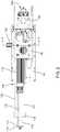
- FIG. 1is a top perspective view of a dispensing apparatus in accordance with the disclosure.
- FIG. 2is a top plan view of the dispensing apparatus shown in FIG. 1 .
- FIG. 3is a bottom perspective view of the dispensing apparatus shown in FIG. 1 , illustrating a fluid cartridge in place within a cartridge holder, and a clamshell member in a partially open position.
- FIG. 4is a bottom plan view of the dispensing apparatus shown in FIG. 1 .
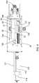
- FIG. 5is a front plan view of the dispensing apparatus shown in FIG. 1 .
- FIG. 6Ais a cross-sectional side elevation view of the dispensing apparatus taken along line 6 A- 6 A of FIG. 5 .
- FIG. 6Bis an enlarged view of a portion of the cross-sectional view shown in FIG. 6A .
- FIG. 6Cis an isometric view of a cartridge mating member in accordance with the disclosure.
- FIG. 7is a rear cross-sectional view of the dispensing apparatus taken along line 7 - 7 of FIG. 2 .
- FIG. 8is a cross-sectional view of a dispense section of the dispensing apparatus in accordance with the disclosure.
- FIG. 9is a cross-sectional view of a piston rod and piston head of a cartridge actuator assembly in accordance with the disclosure.
- FIG. 10is a front view of the piston head shown in FIG. 9 .
- FIG. 11is an isometric view of an end effector assembly connected to a dispense section of the dispensing apparatus in accordance with the disclosure.
- FIG. 12is a cross-sectional view of the end effector assembly connected to a dispense section of the dispensing apparatus shown in FIG. 11 .
- FIGS. 1-7illustrate a robot-mountable cartridge type dispensing apparatus 10 , also referred to as a dispenser 10 , for dispensing from a cartridge various types of fluids, including but not limited to polysulfides, urethanes, epoxies, adhesives, and silicones.
- the dispensing apparatus 10utilizes a fluid cartridge 12 including a cartridge body 14 having a distal end 16 adapted to discharge fluid, a proximal end 18 adapted to receive a piston rod 120 , and a fluid space 20 extending between the distal and proximal ends 16 , 18 .
- a plunger 22is positioned in the fluid space 20 and is movable from the proximal end 18 toward the distal end 16 under a force applied by the piston rod 120 .
- the dispensing apparatus 10also comprises a housing frame 24 having a first robot mounting plate 26 and a second robot mounting plate 28 .
- the robot mounting plates 24 , 26are each configured to removably secure the dispenser 10 to a robot, such as a robotic arm configured to control movement of the dispenser to desired locations during the dispensing operation for precise and controlled placement of fluid at an application site.
- the dispensing apparatus 10also comprises a cartridge holder 30 including a first clamshell member 32 and a second clamshell member 34 .
- the cartridge holder 30is configured to receive the cartridge 12 in a cartridge holding space 36 .
- At least one of the clamshell members 32 , 34is movable toward and away from the other of the clamshell members 32 , 34 for allowing the cartridge 12 to be received in and removed from the holding space 36 .
- the dispenser 10may be sized to accommodate a variety of cartridge sizes, such as a 6 oz. capacity cartridge or a 12 oz. capacity cartridge.
- the dispensing apparatus 10further includes a dispense section 40 having a discharge passage 42 and a discharge outlet 44 .
- a fluid mating member 200may be coupled to the discharge outlet 44 for further directing the discharged fluid from the dispensing apparatus 10 to an end effector assembly 300 , such as dispensing nozzle or an applicator brush.
- the fluid mating member 200serves as an adapter to connect the end effector assembly 300 to the dispense section 40 in fluid communication.
- the discharge passage 42communicates with a suitable fluid supply in the cartridge.
- the discharge passage 42communicates with the cartridge holding space 36 such that the discharge passage 42 receives fluid from a distal outlet passage 38 of the fluid cartridge 12 when the fluid cartridge 12 is received between the first and second clamshell members 32 , 34 .
- the distal outlet passage 38serves as the supply passage to the dispense section 40 .
- a cartridge mating member 440may be coupled to the distal outlet passage 38 , as will later be described in greater detail.
- a first seal 54is located in surrounding relation to an inlet 56 of the discharge passage 42 .
- This seal 54may be a face seal that engages a distal tip element 58 of the fluid cartridge 12 .
- the seal 54abuts against an outer surface 58 a of the distal tip element 58 that faces in the same direction as the flow of fluid from the cartridge 12 .
- the fluidis further directed to the discharge outlet 44 during a dispensing operation.
- the first clamshell member 32is fixed to the housing frame 24 of the dispensing apparatus 10
- the second clamshell member 34is pivotably movable relative to the stationary first clamshell member 32
- a pair of hinges 39 a , 39 b provided on a side of the cartridge holder 30pivotably connect the second clamshell member 34 to the first clamshell member 32 , such that the second clamshell member 34 may be pivoted between an open position and a closed position.
- the open positionallows for loading and unloading of the cartridge 12
- the closed positionallows for dispensing fluid from the cartridge 12 .
- the dispensing apparatus 10further includes a locking member 130 configured to secure the cartridge holder 30 in the closed position by clamping the first and second clamshells together.
- the locking member 130is provided proximate to the side of the cartridge holder 30 opposite the hinges 39 a , 39 b , and is movably connected to a locking actuator 132 .
- the locking actuator 132is fixed to a side of the housing frame 24 and is configured move the locking member 130 in and out of locking engagement with the first and second clamshells 32 , 34 .
- the locking actuator 132may comprise a pneumatic driver and a reciprocating rod 134 that is coupled to the locking member 130 .
- the locking member 130may comprise a first flange member 135 and an oppositely spaced apart second flange member 137 that are configured to mate with a corresponding first shoulder 35 formed on the first clamshell member 32 and a second shoulder 37 formed on the second clamshell member 34 , respectively.
- the movable clamshell half 34is actuated between an open position and a closed position by a clamshell actuator 160 .
- the clamshell actuator 160may comprise a pneumatic cylinder 161 having a reciprocating rod 162 coupled to the pivotable clam shell half 34 via a connector rod 163 , or by other means.
- the dispense section 40further includes a dispense valve assembly 60 coupled with a dispense valve actuator 70 for moving a dispense valve 62 between an open position and a closed position.
- a dispense valve assembly 60may include a snuff back mechanism, as will be further discussed below. It should be appreciated that other types of valves may also be used, including those without a snuff-back mechanism.
- the dispense valvemay be configured to operate a snuff back operation.
- the dispense valve assembly 60 and/or any of its elementsmay be made of any suitable material including steel, hardened steel or any other suitable substance, such as plastic for minimizing cured material adhesion. Accordingly, the dispense valve assembly 60 may comprise a snuff back element 80 and a dispense valve 62 having a valve rod 64 .
- the snuff back mechanismcomprises a snuff back element 80 having an hourglass shape that is slidably mounted within a snuff back passage 82 located between the discharge passage 42 and the discharge outlet 44 . More particularly, the snuff back passage 82 intersects with, and therefore, fluidly communicates with the discharge passage 42 . Further, the snuff back passage 82 aligns with, and therefore, fluidly communicates with the discharge outlet 44 .
- the snuff back element 80is configured to reciprocate within the snuff back passage 82 by moving forward and backward in response to the dispense valve actuator 70 , such that the snuff back element 80 is movable between a respective flow position and a snuff back position.
- a cartridge actuator assembly 100is configured to dispense fluid from the cartridge 12 .
- the cartridge actuator assembly 100includes a motor 110 , a drive rod 112 coupled to the motor, a piston rod 120 , and an actuator linkage member 116 configured to couple the drive rod 112 to the piston rod 120 .
- the motor 110is a servomotor configured to linearly move the drive rod 112 in a reciprocating manner.
- other types of motorsmay be used, including a rotary motor or a linear motor. Use of such a servomotor has been found to improve reliability of the actuator assembly since it is capable of producing greater thrust than conventional actuator assemblies, while also providing a positive displacement of the fluid material.
- the servomotormay generate a force on the plunger that results in pressures up to 400 psi or higher for dispensing highly viscous fluids.
- movement of the piston rod 120may be driven by a pneumatic actuator, a hydraulic actuator, or other suitable device.
- a first end 117 of the actuator linkage member 116is secured to an end of the drive rod 112 by a rod fastener 114 , such as a threaded nut.
- a second end 118 of the actuator linkage member 116is attached to a first end of the piston rod 120 . Accordingly, reciprocating movement of the drive rod 112 caused by the servomotor likewise results in reciprocating movement of the piston rod 120 .
- the piston rod 120extends from the actuator linkage member in a direction toward the cartridge holding space 36 of the cartridge holder 30 , such that the piston rod 120 and the cartridge are coaxially aligned when the cartridge is placed within the cartridge holder 30 .
- the piston rod 120 and the drive rodare arranged substantially parallel to each other.
- At least one auxiliary piston rod 122may also be connected to the actuator linkage member 116 and configured to move along with the piston rod 120 and the drive rod 112 for providing additional support and stability. Such an auxiliary piston rod 122 is also arranged substantially parallel to the piston rod 120 and the drive rod 112 . Both the piston rod 120 and the auxiliary piston rod 122 may be rigidly fixed to the actuator linkage member 116 , or removably attached via fasteners such as screws and bolts, among others.
- the piston rod 120includes a piston head 140 configured to matingly engage the plunger 22 of the cartridge in order to move the plunger 22 through the fluid cartridge 12 during a dispense operation, as will later be described below.
- the dispense valve 62includes a valve rod 64 that is movable between the closed position shown, in which no fluid may flow from the fluid cartridge 12 through the discharge passage 42 to the discharge outlet 44 , and an open position in which fluid is allowed to flow from the fluid cartridge through the discharge passage to the discharge outlet 44 .
- the dispense valve 62may be operated in a reciprocating manner between the open and closed positions by operating the dispense valve actuator 70 with pressurized air.
- the dispense valve 62may be a rotary ball valve, a ball and seat valve, a pinch tube, or other types on/off control valves.
- the dispense valve actuatorcomprises a pneumatic valve piston 72 housed within a valve actuator housing 74 , and more specifically, within a cylindrical bore 75 .
- a proximal end of the valve rod 64is connected to the pneumatic valve piston 72
- a distal end of the valve rod 64is connected to the snuff back element 80 .
- the bore 75receives pressurized air on one side 76 a of the piston 72 for moving both the valve rod 64 and the snuff back element 80 simultaneously in the direction of the arrow 90 , thus moving the dispense valve 62 to an open position.
- the bore 75also receives pressurized air on the opposite side 76 b of the piston 72 to simultaneously move the valve rod 64 and the snuff back element 80 in the opposite direction, thus moving the dispense valve 62 to the closed position shown.
- the snuff back element 80is simultaneously actuated to a flow position by moving toward the discharge outlet 44 .
- the hour glass shape of the snuff back element 80defines a thick, or wide, region 85 and a directly adjacent thin, or narrow, region 86 .
- the thick region 85sealingly abuts a resilient valve seal 84 , such as an elastomeric O-ring, provided at the intersection of the snuff back passage 82 and the discharge outlet 44 when the dispense valve 62 is in the closed position.
- a resilient valve seal 84such as an elastomeric O-ring
- the thin region 86 of the snuff back element 80is positioned concentrically within the valve seal 84 in the flow position.
- the thin region 86 of the snuff back element 80does not sealingly abut the valve seal 84 , and thus fluid is allowed to flow past the snuff back element 80 toward the discharge outlet 44 when dispense valve 62 is opened.
- the thick region 85 of the snuff back element 80moves into the discharge outlet 44 when the dispense valve is in the open position.
- the thick region 85 of the snuff back element 80has a smaller diameter than the diameter of the discharge outlet 44 , so that fluid flow through the discharge outlet 44 is not blocked or impeded by the thick region 85 of the snuff back element 80 when in the flow position.
- the plunger 22 of the fluid cartridge 12is moved from the proximal end 18 to the distal end 16 of the cartridge body 14 by a force applied by the piston rod 120 of the cartridge actuator assembly 100 against the proximal end 22 a of the plunger 22 .
- a piston head 140is removably attached to the piston rod 120 .
- a distal end 141 of the piston head 140is threadedly engaged to a distal end 121 of the piston rod 120 .
- the piston head 140may be configured to accommodate fluid cartridges 12 of different lengths, different diameters, and different fluid volume capacities.
- the piston head 140may further be designed to accommodate for differences that occur due to resulting tolerance variations of the cartridge 12 caused during manufacturing.
- a resilient piston seal 142is provided on the piston head 140 between a shoulder 143 of the piston head 140 and an annular seal retainer 144 .
- the seal 142 and seal retainer 144are secured in place by a fastening member 145 , such a threaded nut.
- the seal 142prevents fluid leakage between the piston head 140 and the cartridge 12 during the dispensing operation since the integrity of the seal 142 is maintained even when the tolerances of the outer diameter and the inner diameter of the cartridge vary.
- the piston rod 120defines an internal piston passageway 124 that is in fluid communication with an internal piston head passageway 146 .
- a proximal end 147 of the piston head 140includes a vent outlet defining at least one vent hole 148 that is in fluid communication with the piston head passageway 146 .
- the proximal end 147 of the piston head 140is also configured to matingly interface with the proximal end 22 a of the plunger 22 of the cartridge in order to maintain the integrity of the plunger 22 during dispensing by preventing it from rolling over or changing shape under pressure. Maintaining the integrity of the plunger 22 further helps prevent fluid leakage between the plunger 22 and the interior walls of the cartridge 12 .
- the piston head 140when the piston head 140 enters the cartridge 12 and moves the plunger 22 therethrough to push the fluid out of the cartridge 12 , it may be difficult to then move the piston head 140 proximally back out of the cartridge 12 . This difficulty may be caused by a vacuum formed between the piston head 140 and the plunger 22 as a result of moving the piston rod 120 distally without having any fluid return to the cartridge 12 .
- the at least one vent hole 148provides ventilation in order to prevent vacuum pressure when the piston head 140 pushes the plunger 22 during the dispense operation.
- the piston head 140includes an arrangement of a plurality of vent holes 148 , such as five holes, which help to relieve pressure formed when the piston head 140 enters the cartridge and engages the plunger 22 .
- the presence of the at least one vent hole 148allows for a flow of air into the piston head passageway 146 once the piston head 140 enters the cartridge to urge the plunger 22 during dispensing.
- the presence of multiple vent holes 148allows for a flow of air even if some of the vent holes become clogged with leaked fluid material.
- each of the vent holes 148may be the same size.
- the vent holes 148may be different sizes.
- the vent holes 148may further be arranged in any number of patterns and may be any number of sizes depending on the size of the cartridge.
- each cartridgemay change depending on the temperature and other tolerances held during manufacturing, it is necessary to maintain the integrity of the cartridge during the dispensing operation when the pressure inside the cartridge is increased, in order to avoid breaking the cartridge and having fluid material flow uncontained throughout the dispenser. Furthermore, the cartridge is captured and retained in position so that it can be pressurized. Accordingly, when the piston head 140 matingly interfaces with the plunger 22 , the air trapped therebetween flows through the at least one vent hole 148 and into the piston head passageway 146 for relieving vacuum pressure within the cartridge. As previously described, the piston head 140 may be threadedly attached to the piston rod 120 so that it can easily be removed and cleaned or replaced in the event of fluid leakage.
- the cartridge 12may contain a two-part curing material, such as a polysulfide two-component premixed and frozen material.
- the distal end of the piston head 140may be configured to attach to an internal safety hose 125 , such as a vinyl hose, extending through the piston rod passageway 124 of the piston rod 120 .
- the distal end of the piston head 140includes internal threads 141 for threadedly engaging a push fitting to connect to the hose 125 .
- the internal safety hose 125prevents leaked fluid material from adhering to, gumming up, or otherwise clogging the interior passageway 124 of the piston rod 120 .
- the internal hose 125extends through the piston rod 120 and terminates in a pig tail end so that an operator can connect to the pig tail end and blow out material from the hose. Without the safety hose, any leaked fluid material that enters the piston head passageway and/or the piston rod passageway could harden and block airflow, thus rendering the components unusable for venting air.
- the dispense valve 60When the plunger 22 has reached the end of its travel during a dispensing operation, or otherwise when a dispense cycle or operation is complete, the dispense valve 60 is moved by the dispense valve actuator 70 to the closed position as shown in FIG. 8 .
- This actionsimultaneously moves the snuff back element 80 from the flow position to the snuff back position also shown, by introducing pressurized air on the top of the pneumatic valve piston 72 and exhausting air from below the piston.
- This snuff back actiondraws fluid back from the discharge outlet 44 , including any nozzle 310 or other dispensing element coupled to the discharge outlet 44 , in order to prevent drooling of fluid from the dispensing apparatus 10 after the dispense cycle or operation is complete.
- the fluidis drawn from the discharge outlet 44 and into the snuff back passage 82 due to suction caused by vacuum pressure created when the thick region 85 of the snuff back element 80 retracts from the discharge outlet 44 and into sealing abutment with the valve seal 84 .
- the piston head 140can be removed from the cartridge by operating the servomotor in the reverse direction to retract the piston rod 120 .
- the dispensed cartridge 12may then be removed from the cartridge holder 30 , and a new cartridge may be placed in the dispensing apparatus 10 .
- the dispensermay include a cartridge ejector 170 configured to eject the fluid cartridge 12 at the end of the dispense cycle and/or when the fluid cartridge 12 is empty and in need of replacement.
- the cartridge ejector 170may be used to eject the cartridge 12 from the holding space 36 after the clam shells 32 , 34 of the cartridge holder 30 have been unclamped by actuating the locking member 130 to the unlocked position as previously described above.
- the cartridge ejector 170comprises a pneumatic actuator 172 defining a cylindrical ejector housing and a pneumatic ejector piston 174 mounted for reciprocation within the ejector housing.
- the ejector piston 174is coupled to an ejector element 176 that is configured to engage and lift at least the distal tip element 58 and the distal end 16 of the cartridge 12 .
- the cartridge 12may be grasped either manually or in an automated manner, such as by a robotic grasping mechanism.
- the cartridge ejector 170may comprise a lever configured to eject a cartridge.
- the cartridgemay include a flange 430 defining a flange stop surface 432 configured to retain the cartridge 12 within the dispenser 10 .
- the flange stop surface 432abuts against a distal stop surface 434 defined by the clam shell halves 32 to limit the travel of the cartridge 12 in a distal direction.
- the flange 430is located in a flange groove 438 defined by the clam shell halves 32 , 34 .
- a proximal stop surface 436 defined by the clam shell halves 32will engage the flange 430 to limit the axial travel of the cartridge in the proximate direction.
- the flange groove 438is defined in part by the distal stop surface 434 and the proximal stop surface 436 .
- the cartridge 12connects with a cartridge mating member 440 having a projection 442 .
- a projection receiver 444 located in the distal end 16 of the cartridge 12fits over the projection 442 to attach the cartridge 12 to the cartridge mating member 440 in a sealed manner.
- the projection receiver 444 on the cartridge 12can slip over the projection 442 when the cartridge 12 is pushed on to the cartridge mating member 440 .
- the projection receiver 444flexes to fit over the projection 442 .
- the flexure of the projection receiver 444may be limited by a retaining ring 446 .
- a space 448 between the retaining ring 446 and the projection receiver 444indicates the amount the projection receiver 444 may flex before it is stopped by the retaining ring 446 .
- the projection 442is used to connect the cartridge 12 to the dispenser 10 and provide fluid communication between the cartridge 12 and the discharge passage in a sealed manner.
- the projection receiver 444has a retaining band 450 on the projection 442 .
- the supply passageis defined by an interior passageway 452 of the cartridge mating member 440 that provides fluid communication between the cartridge 12 and the discharge passage through the projection 442 and the body 454 of the cartridge mating member 440 .
- a fillet 458may be provided between the projection 442 and the body 454 . It will be appreciated that moving the projection receiver 444 over the projection 442 may cause some flexure of the projection receiver 444 , and moving the projection receiver 444 over the retaining band 450 will cause the greatest flexure of the projection receiver 444 .
- the retaining band 450may have a smooth surface to facilitate flexure and movement of the projection receiver 444 over the retaining band 450 .
- the retaining band 450may have a relief area that has a slightly larger interior diameter that the interior diameter of the rest of the projection receiver 444 .
- the retaining band relief areamay cause the projection receiver 444 to flex back toward its non-flexed or less-flexed position when the retaining band 450 is aligned with the retaining band relief area. This creates a bias toward the projection receiver 444 to maintain the retaining band relief area aligned with the retaining band 450 .
- the dispenser 10may be equipped with an end effector assembly 300 .
- the end effector assembly 300may be removably attached to the dispense section 40 for dispensing the fluid or adhesive.
- the end effector assembly 300may include a dispensing brush.
- Various types of dispensing brushesmay be used, such as those made of ABS-M30 housing, and epoxy set with white horsehair.
- the brushesmay be made from plastic or other suitable material.
- the end effector assembly 300may be a nozzle 310 configured to connect directly to the fluid mating member and in fluid communication with the discharge outlet 44 for dispensing fluid from the dispensing apparatus 10 , as shown in FIG. 8 .
- the end effector assembly 300may include material cut-off and/or material handling valves, such as a snuff-back valve, a ball and seat valve, and a rotary valve, among others.
- the end effector assembly 300comprises a mounting plate assembly 320 including a motor mounting plate 322 and an end effector mounting plate 324 .
- the motor mounting plate 322includes motor mounting fasteners 325 for attaching a motor 327 to the motor mounting plate 322 .
- the end effector mounting plate 324is attached to the motor mounting plate 322 .
- a tube 326 and hose 328may also be mounted to the end effector mounting plate 324 .
- the fluid mating member 200extends through a hole in the motor mounting plate 322 and is configured to releasably connect to a fluid mating receiver 330 .
- a hose connection 332provides a way to connect the hose 328 to the fluid mating receiver 330 and provide fluid communication between the hose 328 and an internal fluid passageway 202 of the fluid mating member 200 .
- the fluid mating receiver 330is configured to attach in a sealing manner to a fluid mating projection 204 of the fluid mating member 200 .
- the fluid mating projection 204 of the fluid mating member 200includes a tapered surface which is dimensioned to fit into the correspondingly dimensioned fluid mating receiver 330 .
- the fluid or adhesive in the interior fluid passageway 202is transmitted through the fluid mating projection 204 to the fluid mating receiver 330 .
- the fluid mating projection 204may include fluid mating member seals 206 that reside in fluid mating member seal grooves 208 . These seals 206 are located in the seal grooves 208 to ensure that when the end effector assembly 300 is attached to the dispense section 40 of the dispenser 10 , the fluid mating projection 204 is fluidly sealed to the fluid mating receiver 330 in order to prevent leakage.
- the seals 206may be resilient seals, such as elastomeric O-rings.
- the motor 327includes a power output shaft 340 which connects to a power transmitting shaft 342 via a power transmission mechanism, such as a power coupler 344 .
- the power from the motor 327is in turn transmitted to the at least one dispensing brush.
- the end effector assembly 300includes an adjustable elongating mechanism 350 comprising a drive chain with drive gears, such as sprockets 350 a , 350 b , 350 c , 350 d , and 350 e .
- the end effectormay be driven by a drive belt or gears.
- At least one brush configured to rotatemay be attached to the end of the adjustable mechanism 350 .
- the adjustable mechanism 350uses the drive chain and drive gears to transmit the rotating motion to the brush.
- the brushmay be attached to the final sprocket 350 e to allow the brush to rotate.
- the hose 328transmits fluid to an axial opening of the brush via a hose connection 332 which is part of the brush mounting assembly 352 , and which allows the brush to be connected to the sprocket 350 e .
- the drive chainmay be covered with a housing 354 .
- a hose housing 356may provide some protection for the hose 328 .
- a hose clip 329may attach the hose 328 to the tube 326 .
- the tube 326may have an octagonal, hexagonal, or other suitably shaped cross section to fit into a correspondingly shaped hole in the end effector mounting plate 324 .
- the brushmay be oriented at different angular positions with respect to the end effector mounting plate 324 .
- the tube 326may also be of different lengths as desired to provide the brush in a desired position.
- the end effector assembly 300is configured to quickly connect and disconnect to the dispense section 40 via an adapter such as the fluid mating member 200 .
- the fluid mating member 200may be equipped with pivotable attaching fingers 210 each having an oppositely disposed hook shape defining attaching surfaces.
- the attaching fingers 210are configured to pivotably engage and secure together the motor mounting plate 322 and the end effector mounting plate 324 .
- the fluid mating receiver 330is located in the end effector mounting plate 324 .
- the fluid mating receiver 330is mounted loosely to the end effector mounting plate 324 so that it can “float” by moving radially within the end effector mounting plate 324 to align and position itself during a mating operation with a fluid mating projection 204 of the fluid mating member 200 .
- the fluid mating receiver 330connects to the hose 328 via a hose connection 332 and allows the inside of the fluid mating receiver 330 to fluidly communicate with the interior of the hose.
- the motor mounting plate 322includes a mounting structure configured to connect to the end effector assembly 300 .
- the motor 327has a power output shaft 340 that connects to a power coupler 344 .
- the power coupler 344has a large axial hole 345 in which the power output shaft 340 extends.
- the exterior of the power output shaft 340 and the interior of the large axial hole 345may be hexagonally, octagonally, or some other suitably shaped cross section to allow the power output shaft 340 to grip the walls of the large axial hole 345 without spinning with respect to the power coupler 344 .
- the power coupler 344also has a small axial hole 346 which also may be be hexagonally, octagonally, or some other suitably shaped cross section to allow the power coupler 344 to attach to the power transmitting shaft 342 . It should be appreciated that the power transmitting shaft 342 also may have a corresponding hexagon, octagon, or other suitable shaped cross section in order to allow the power coupler 344 to rotate with and transmit torque from the motor 327 without slipping with respect to the power transmitting shaft 342 .
- a biasing membersuch as a spring 348 , biases the power coupler 344 toward the power transmitting shaft 342 .
- the power transmitting shaft 342aids in transmitting rotational energy and torque from the motor 327 to the drive chain.
- the end effector assembly 300attaches to the rest of the dispense section of the dispenser 10 via attaching fingers.
- the attaching fingerswill pivot over the end effector mounting plate 324 until the motor mounting plate 322 is moved close enough to allow the attaching fingers to snap back due to the urging of the a resilient member, such as a spring, and place the attaching surfaces of the attaching fingers in a locking position on a shoulder of the end effector mounting plate 324 .
- the attaching fingersare pivoted against the urging of the resilient member, thereby moving the attaching surfaces on the attaching fingers from the shoulder on the mounting plate 322 .
- the end effector assembly 300may then be separated from the rest of the dispenser 10 .
- operation of the dispenser 10may be controlled by a controller or a plurality of controllers connected to various elements of the dispenser 10 .
- controllersmay be used, including local controllers and/or remote controllers. Further, the controllers may have wired or wireless connections.
Landscapes
- Coating Apparatus (AREA)
- Engineering & Computer Science (AREA)
- Robotics (AREA)
- Electromagnetic Pumps, Or The Like (AREA)
- Reciprocating Pumps (AREA)
- Spray Control Apparatus (AREA)
Abstract
Description
Claims (26)
Priority Applications (4)
| Application Number | Priority Date | Filing Date | Title |
|---|---|---|---|
| US15/426,999US10675653B2 (en) | 2017-02-07 | 2017-02-07 | Motorized cartridge type fluid dispensing apparatus and system |
| EP18155425.4AEP3381573A3 (en) | 2017-02-07 | 2018-02-06 | Motorized cartridge type fluid dispensing apparatus and system |
| JP2018019000AJP2018126734A (en) | 2017-02-07 | 2018-02-06 | Motorized cartridge type fluid dispensing apparatus and system |
| CN201810122122.6ACN108435454A (en) | 2017-02-07 | 2018-02-07 | Motorization cartridge fluid distributing equipment and system |
Applications Claiming Priority (1)
| Application Number | Priority Date | Filing Date | Title |
|---|---|---|---|
| US15/426,999US10675653B2 (en) | 2017-02-07 | 2017-02-07 | Motorized cartridge type fluid dispensing apparatus and system |
Publications (2)
| Publication Number | Publication Date |
|---|---|
| US20180221909A1 US20180221909A1 (en) | 2018-08-09 |
| US10675653B2true US10675653B2 (en) | 2020-06-09 |
Family
ID=61187118
Family Applications (1)
| Application Number | Title | Priority Date | Filing Date |
|---|---|---|---|
| US15/426,999Expired - Fee RelatedUS10675653B2 (en) | 2017-02-07 | 2017-02-07 | Motorized cartridge type fluid dispensing apparatus and system |
Country Status (4)
| Country | Link |
|---|---|
| US (1) | US10675653B2 (en) |
| EP (1) | EP3381573A3 (en) |
| JP (1) | JP2018126734A (en) |
| CN (1) | CN108435454A (en) |
Cited By (1)
| Publication number | Priority date | Publication date | Assignee | Title |
|---|---|---|---|---|
| US12214375B2 (en) | 2019-08-29 | 2025-02-04 | Medmix Switzerland Ag | Cartridge holder for a dispenser |
Families Citing this family (13)
| Publication number | Priority date | Publication date | Assignee | Title |
|---|---|---|---|---|
| CN107787254B (en)* | 2015-06-11 | 2021-01-15 | 诺信公司 | Cartridge fluid dispensing apparatus |
| US10675653B2 (en) | 2017-02-07 | 2020-06-09 | Nordson Corporation | Motorized cartridge type fluid dispensing apparatus and system |
| EP3401554B1 (en)* | 2017-05-12 | 2020-04-15 | Hamilton Sundstrand Corporation | Nozzle assembly |
| EP3703872A1 (en)* | 2017-10-30 | 2020-09-09 | Nordson Corporation | Dispense valve with disposable fluid body |
| CN109277259B (en)* | 2018-10-26 | 2023-10-10 | 东莞市开来电子有限公司 | Air pressure protection device for preventing glue from flowing backwards |
| US10682663B2 (en)* | 2018-10-31 | 2020-06-16 | The Boeing Company | Methods for dispensing flowable materials |
| CN110479543B (en)* | 2019-09-19 | 2021-04-16 | 昆山石林绿化有限责任公司 | Device is paintd to trees insect prevention lime median |
| CN110594122A (en)* | 2019-10-11 | 2019-12-20 | 王江荣 | Reciprocating vehicle reciprocating push-pull lever arm re-push-pull multipurpose giant pumping and pushing equipment |
| JP7534655B2 (en)* | 2019-12-24 | 2024-08-15 | 株式会社スリーボンド | Material application device and pressing member |
| DE102020110743A1 (en) | 2020-04-21 | 2021-10-21 | Atlas Copco Ias Gmbh | Device for dosing viscous material |
| CN113663880A (en)* | 2020-05-15 | 2021-11-19 | 上海发那科机器人有限公司 | Gluing quantitative control device |
| CN113102173B (en)* | 2021-03-08 | 2022-07-08 | 东莞市国信精密科技有限公司 | High-precision dispensing equipment for assembly in communication industry |
| TWI846270B (en) | 2023-01-16 | 2024-06-21 | 辛耘企業股份有限公司 | Liquid injection device |
Citations (80)
| Publication number | Priority date | Publication date | Assignee | Title |
|---|---|---|---|---|
| US1555711A (en) | 1921-10-26 | 1925-09-29 | Harry B Hershinger | Grease gun |
| US1709445A (en) | 1927-03-31 | 1929-04-16 | Tomes Percy Austen | Gun for ejecting plastic material |
| US3443725A (en) | 1967-10-24 | 1969-05-13 | Charles L Lawhorn | Pistol dispenser for fluent material |
| US3767085A (en) | 1971-08-02 | 1973-10-23 | J Cannon | Mixing syringe |
| US3851801A (en) | 1971-02-15 | 1974-12-03 | Involvo Ag Verpackungsmaschine | Dispensing device having lost motion piston pump |
| FR2556984A3 (en) | 1983-12-27 | 1985-06-28 | Technomastic B B Srl | Portable electromechanical gun for discharging cartridges - of fusible adhesives or sealants etc. to provide adjustable or constant rates of discharge |
| US4641764A (en) | 1985-05-09 | 1987-02-10 | Slautterback Corporation | Viscous thermoplastic melting and dispensing unit |
| US4724983A (en) | 1986-01-02 | 1988-02-16 | Claassen Henning J | Apparatus for liquefying a thermoplastic plastic |
| US4771920A (en) | 1985-10-29 | 1988-09-20 | Nordson Corporation | Thermoplastic grid melter |
| US4811863A (en) | 1987-01-26 | 1989-03-14 | Claassen Henning J | Apparatus for liquefying a thermoplastic plastic |
| EP0311256A1 (en) | 1987-10-03 | 1989-04-12 | Bostik Limited | Applicators for hot-melt materials |
| US4846373A (en) | 1982-09-07 | 1989-07-11 | Penn Laurence R | Apparatus for proportioning or for proportioning and mixing plural different fluid compositions |
| US4878981A (en) | 1987-05-22 | 1989-11-07 | Print Kiko Co., Ltd. | Form collator gluing apparatus |
| US4925061A (en) | 1987-05-06 | 1990-05-15 | Milbar Corporation | Fluid actuated dispenser |
| US4932094A (en) | 1988-12-22 | 1990-06-12 | The Boeing Company | Liquid applicator tool |
| US4974752A (en) | 1989-11-27 | 1990-12-04 | Sirek Andrew J | Heated caulk dispensing gun |
| US5069365A (en) | 1989-05-31 | 1991-12-03 | Woodhouse Robert C | Chemical dispensing system |
| US5074443A (en) | 1989-12-20 | 1991-12-24 | Nordson Corporation | Adaptor for liquid dispensing syringe |
| US5318207A (en) | 1992-04-20 | 1994-06-07 | Nordson Corporation | Method and apparatus for portable dispensing of foam material |
| US5435462A (en) | 1993-01-20 | 1995-07-25 | Nordson Corporation | Liquid cartridge storage case for use with liquid dipenser |
| US5458275A (en) | 1994-07-11 | 1995-10-17 | Liquid Control Corporation | Positive-displacement dispensing device |
| US5461922A (en) | 1993-07-27 | 1995-10-31 | Lucas-Novasensor | Pressure sensor isolated within housing having integral diaphragm and method of making same |
| US5467899A (en) | 1994-02-08 | 1995-11-21 | Liquid Control Corporation | Dispensing device for flowable materials |
| US5566860A (en) | 1994-09-08 | 1996-10-22 | Liquid Control Corporation | Dual component cartridge |
| US5657904A (en) | 1995-10-17 | 1997-08-19 | Nordson Corporation | High flow melting grid and melter unit |
| US5733597A (en) | 1992-07-08 | 1998-03-31 | Nordson Corporation | Snuff back controlled coating dispensing apparatus and methods |
| US5799578A (en) | 1994-04-15 | 1998-09-01 | Heidelberger Druckmaschinen Aktiengesellschaft | Printing press and liquid supply |
| US5836482A (en) | 1997-04-04 | 1998-11-17 | Ophardt; Hermann | Automated fluid dispenser |
| US5852244A (en) | 1995-10-03 | 1998-12-22 | Nt International, Inc. | Non-fluid conducting pressure sensor module having non-contaminating body and isolation member |
| US5875928A (en) | 1995-01-13 | 1999-03-02 | Bayer Aktiengesellschaft | Device for mixing and discharging a molding composition |
| US5906682A (en) | 1995-10-13 | 1999-05-25 | Nordson Corporation | Flip chip underfill system and method |
| US5927560A (en)* | 1997-03-31 | 1999-07-27 | Nordson Corporation | Dispensing pump for epoxy encapsulation of integrated circuits |
| US5944226A (en) | 1997-06-09 | 1999-08-31 | Liquid Control Corporation | Add-on valve assembly for dual-component cartridge |
| US5984147A (en) | 1997-10-20 | 1999-11-16 | Raytheon Company | Rotary dispensing pump |
| US6036106A (en) | 1999-02-04 | 2000-03-14 | Nordson Corporation | Dispenser having liquid discharge assembly with high wear and thermal conductivity properties |
| US6105822A (en) | 1999-09-08 | 2000-08-22 | Liquid Control Corporation | Device and method for mixing and dispensing two flowable materials |
| US6131770A (en) | 1998-10-15 | 2000-10-17 | Nordson Corporation | Hot melt delivery system |
| US6234359B1 (en) | 1998-03-20 | 2001-05-22 | Liquid Control Corporation | System for reloading dispensing tools |
| US6234358B1 (en) | 1999-11-08 | 2001-05-22 | Nordson Corporation | Floating head liquid dispenser with quick release auger cartridge |
| US6299023B1 (en) | 2000-08-24 | 2001-10-09 | Miles Arnone | Device for dispensing two substances in a user selectable ratio with replaceable cartridges |
| US6308868B1 (en)* | 1999-09-20 | 2001-10-30 | Liquid Control Corporation | High pressure cartridge feed system |
| US6311868B1 (en) | 1998-04-06 | 2001-11-06 | New Sensations, L.L.C. | Dispenser which incrementally heats fluids with substantial non-volatile constituent parts |
| US20020043539A1 (en)* | 2000-06-30 | 2002-04-18 | Pagel Russel T. | Disposable syringe dispenser system |
| US6422427B1 (en) | 1998-03-20 | 2002-07-23 | Liquid Control Corp | Dispensing tool and system for reloading the tool |
| US20020130141A1 (en) | 2001-02-01 | 2002-09-19 | Dispensing Technologies International Corporation (Dtic) | Fluid dispenser particularly adapted for hand-held operation |
| US20030044219A1 (en)* | 2001-08-29 | 2003-03-06 | Closure Medical Corporation | Microapplicators, delivery systems and methods for adhesives and sealants |
| WO2003051526A1 (en) | 2001-12-14 | 2003-06-26 | Mydata Automation Ab | Viscous medium feeder |
| US20030122095A1 (en) | 2001-12-07 | 2003-07-03 | Wilson Robert F. | Low pressure measurement devices in high pressure environments |
| US6607104B2 (en) | 2001-05-24 | 2003-08-19 | Illinois Tool Works Inc. | Metered output hot melt adhesive dispensing system with return isolation loop |
| US6651849B2 (en) | 1990-06-06 | 2003-11-25 | Lancer Partnership, Ltd. | Dispensing apparatus including a pump package system |
| US6715506B1 (en)* | 1998-12-28 | 2004-04-06 | Musashi Engineering, Inc. | Method and device for injecting a fixed quantity of liquid |
| US20040074927A1 (en) | 2002-10-18 | 2004-04-22 | Lafond Luc Marcel | Portable gas powered fluid dispenser |
| DE10313051A1 (en) | 2003-03-24 | 2004-10-07 | Martin Bodenburg | Cartridge press for portion-wise extraction of paste material, especially hydrocolloids, heating arrangement for accommodation body with aperture for ram for insertion into cartridge |
| US20040226968A1 (en) | 2003-03-04 | 2004-11-18 | Lafond Luc Marcel | Nozzle for dispensable viscous materials |
| US6935541B1 (en) | 2004-08-17 | 2005-08-30 | Black & Decker Inc. | Caulk gun pressurizing system |
| US6957751B2 (en) | 2002-04-16 | 2005-10-25 | Hygiene-Technik Inc. | Vacuum relief device |
| US20060016510A1 (en) | 2004-07-21 | 2006-01-26 | Nordson Corporation | Rechargeable dispensing head |
| JP2006043703A (en) | 2004-08-06 | 2006-02-16 | Pc Cox Ltd | Discharge gun |
| US7033004B2 (en) | 2002-11-07 | 2006-04-25 | T.G.C. S.R.L. | Device for feeding prepackaged ink to the ink duct of printing machines |
| US20060193969A1 (en) | 2005-02-25 | 2006-08-31 | Speedline Technologies, Inc. | Method and apparatus for streaming a viscous material on a substrate |
| US7296707B2 (en) | 2004-06-10 | 2007-11-20 | Graco Minnesota Inc. | Method and apparatus for dispensing a hot-melt adhesive |
| US7331482B1 (en) | 2003-03-28 | 2008-02-19 | Dl Technology, Llc | Dispense pump with heated pump housing and heated material reservoir |
| US20080302477A1 (en) | 2006-01-17 | 2008-12-11 | Nordson Corporation | Apparatus and Method for Melting and Dispensing Thermoplastic Material |
| US20100012743A1 (en)* | 2008-07-16 | 2010-01-21 | Honda Motor Co., Ltd. | Electrostatic painting method and apparatus |
| US7762088B2 (en) | 2003-07-14 | 2010-07-27 | Nordson Corporation | Apparatus and method for dispensing discrete amounts of viscous material |
| US7896200B2 (en) | 2005-06-10 | 2011-03-01 | Panasonic Corporation | Liquid substance supplying device |
| US20110049189A1 (en) | 2009-09-03 | 2011-03-03 | Hilti Aktiengesellschaft | Extrusion tool |
| US20120252242A1 (en)* | 2011-03-28 | 2012-10-04 | Fishman Corporation | System and Method for Releasably Coupling a Fluid Dispenser to a Dispensing System |
| US8544686B2 (en) | 2009-07-10 | 2013-10-01 | Aervoe Industries, Inc. | System for dispensing sprayable material |
| US8662352B1 (en)* | 2012-10-29 | 2014-03-04 | Nordson Corporation | Fluid dispenser and method for dispensing a fluid including a uniform distribution of composite materials |
| US20140138406A1 (en) | 2012-10-02 | 2014-05-22 | John E. Sanfilippo | Film for flexible bags |
| US20140197198A1 (en)* | 2013-01-17 | 2014-07-17 | Nordson Corporation | Cartridge dispenser |
| US20140326760A1 (en)* | 2013-05-03 | 2014-11-06 | The Boeing Company | Control Valve Having a Disposable Valve Body |
| EP2851133A1 (en) | 2013-09-20 | 2015-03-25 | Nordson Corporation | Fluid dispenser and method for simultaneously dispensing fluids from multiple cartridges |
| US9027796B1 (en) | 2012-03-15 | 2015-05-12 | David M. Leitch | Tool to aid in the caulking process |
| US9095872B2 (en) | 2013-07-26 | 2015-08-04 | The Boeing Company | Feedback control system for performing fluid dispensing operations |
| WO2016201277A1 (en) | 2015-06-11 | 2016-12-15 | Nordson Corporation | Cartridge type fluid dispensing apparatus |
| US20170106401A1 (en)* | 2015-10-15 | 2017-04-20 | The Boeing Company | Systems, apparatuses, and methods for applying glutinous substances |
| US20180221909A1 (en) | 2017-02-07 | 2018-08-09 | Nordson Corporation | Motorized cartridge type fluid dispensing apparatus and system |
| US10328452B2 (en) | 2016-03-08 | 2019-06-25 | Swimc Llc | Dispensing unit and methods for dispensing |
Family Cites Families (7)
| Publication number | Priority date | Publication date | Assignee | Title |
|---|---|---|---|---|
| EP1101538A3 (en)* | 1999-11-16 | 2004-12-15 | Mixpac Systems AG | Electrically driven dispensing apparatus for cartridges |
| JP4145192B2 (en)* | 2003-05-15 | 2008-09-03 | 株式会社フジエ | Adhesive supply device and adhesive cartridge |
| KR100497625B1 (en)* | 2003-07-16 | 2005-07-01 | 임창선 | Apparatus for injecting precisely liquid material |
| EP1735110B8 (en)* | 2004-04-08 | 2008-05-21 | RPC Bramlage DHS B.V. | Cartridge pistol with a cartridge holder |
| CN204134838U (en)* | 2014-07-29 | 2015-02-04 | 宁波信泰机械有限公司 | Packing element clamping device |
| CN104148248A (en)* | 2014-08-18 | 2014-11-19 | 昆山鑫腾顺自动化设备有限公司 | Modular rubber pushing device of dispensing system |
| JP2017023916A (en)* | 2015-07-17 | 2017-02-02 | 三菱重工業株式会社 | Discharge device |
- 2017
- 2017-02-07USUS15/426,999patent/US10675653B2/ennot_activeExpired - Fee Related
- 2018
- 2018-02-06EPEP18155425.4Apatent/EP3381573A3/ennot_activeWithdrawn
- 2018-02-06JPJP2018019000Apatent/JP2018126734A/enactivePending
- 2018-02-07CNCN201810122122.6Apatent/CN108435454A/enactivePending
Patent Citations (89)
| Publication number | Priority date | Publication date | Assignee | Title |
|---|---|---|---|---|
| US1555711A (en) | 1921-10-26 | 1925-09-29 | Harry B Hershinger | Grease gun |
| US1709445A (en) | 1927-03-31 | 1929-04-16 | Tomes Percy Austen | Gun for ejecting plastic material |
| US3443725A (en) | 1967-10-24 | 1969-05-13 | Charles L Lawhorn | Pistol dispenser for fluent material |
| US3851801A (en) | 1971-02-15 | 1974-12-03 | Involvo Ag Verpackungsmaschine | Dispensing device having lost motion piston pump |
| US3767085A (en) | 1971-08-02 | 1973-10-23 | J Cannon | Mixing syringe |
| US4846373A (en) | 1982-09-07 | 1989-07-11 | Penn Laurence R | Apparatus for proportioning or for proportioning and mixing plural different fluid compositions |
| FR2556984A3 (en) | 1983-12-27 | 1985-06-28 | Technomastic B B Srl | Portable electromechanical gun for discharging cartridges - of fusible adhesives or sealants etc. to provide adjustable or constant rates of discharge |
| US4641764A (en) | 1985-05-09 | 1987-02-10 | Slautterback Corporation | Viscous thermoplastic melting and dispensing unit |
| US4771920A (en) | 1985-10-29 | 1988-09-20 | Nordson Corporation | Thermoplastic grid melter |
| US4724983A (en) | 1986-01-02 | 1988-02-16 | Claassen Henning J | Apparatus for liquefying a thermoplastic plastic |
| US4811863A (en) | 1987-01-26 | 1989-03-14 | Claassen Henning J | Apparatus for liquefying a thermoplastic plastic |
| US4925061A (en) | 1987-05-06 | 1990-05-15 | Milbar Corporation | Fluid actuated dispenser |
| US4878981A (en) | 1987-05-22 | 1989-11-07 | Print Kiko Co., Ltd. | Form collator gluing apparatus |
| EP0311256A1 (en) | 1987-10-03 | 1989-04-12 | Bostik Limited | Applicators for hot-melt materials |
| JPH01115466A (en) | 1987-10-03 | 1989-05-08 | Emhart Ind Inc | Hot-melt applicator |
| US4932094A (en) | 1988-12-22 | 1990-06-12 | The Boeing Company | Liquid applicator tool |
| US5069365A (en) | 1989-05-31 | 1991-12-03 | Woodhouse Robert C | Chemical dispensing system |
| US4974752A (en) | 1989-11-27 | 1990-12-04 | Sirek Andrew J | Heated caulk dispensing gun |
| US5074443A (en) | 1989-12-20 | 1991-12-24 | Nordson Corporation | Adaptor for liquid dispensing syringe |
| US6651849B2 (en) | 1990-06-06 | 2003-11-25 | Lancer Partnership, Ltd. | Dispensing apparatus including a pump package system |
| US5318207A (en) | 1992-04-20 | 1994-06-07 | Nordson Corporation | Method and apparatus for portable dispensing of foam material |
| US5733597A (en) | 1992-07-08 | 1998-03-31 | Nordson Corporation | Snuff back controlled coating dispensing apparatus and methods |
| US5435462A (en) | 1993-01-20 | 1995-07-25 | Nordson Corporation | Liquid cartridge storage case for use with liquid dipenser |
| US5461922A (en) | 1993-07-27 | 1995-10-31 | Lucas-Novasensor | Pressure sensor isolated within housing having integral diaphragm and method of making same |
| US5467899A (en) | 1994-02-08 | 1995-11-21 | Liquid Control Corporation | Dispensing device for flowable materials |
| US5799578A (en) | 1994-04-15 | 1998-09-01 | Heidelberger Druckmaschinen Aktiengesellschaft | Printing press and liquid supply |
| US5458275A (en) | 1994-07-11 | 1995-10-17 | Liquid Control Corporation | Positive-displacement dispensing device |
| US5566860A (en) | 1994-09-08 | 1996-10-22 | Liquid Control Corporation | Dual component cartridge |
| US5875928A (en) | 1995-01-13 | 1999-03-02 | Bayer Aktiengesellschaft | Device for mixing and discharging a molding composition |
| US5852244A (en) | 1995-10-03 | 1998-12-22 | Nt International, Inc. | Non-fluid conducting pressure sensor module having non-contaminating body and isolation member |
| US5906682A (en) | 1995-10-13 | 1999-05-25 | Nordson Corporation | Flip chip underfill system and method |
| US5657904A (en) | 1995-10-17 | 1997-08-19 | Nordson Corporation | High flow melting grid and melter unit |
| US5927560A (en)* | 1997-03-31 | 1999-07-27 | Nordson Corporation | Dispensing pump for epoxy encapsulation of integrated circuits |
| US5836482A (en) | 1997-04-04 | 1998-11-17 | Ophardt; Hermann | Automated fluid dispenser |
| US5944226A (en) | 1997-06-09 | 1999-08-31 | Liquid Control Corporation | Add-on valve assembly for dual-component cartridge |
| US5984147A (en) | 1997-10-20 | 1999-11-16 | Raytheon Company | Rotary dispensing pump |
| US6234359B1 (en) | 1998-03-20 | 2001-05-22 | Liquid Control Corporation | System for reloading dispensing tools |
| US6422427B1 (en) | 1998-03-20 | 2002-07-23 | Liquid Control Corp | Dispensing tool and system for reloading the tool |
| US6311868B1 (en) | 1998-04-06 | 2001-11-06 | New Sensations, L.L.C. | Dispenser which incrementally heats fluids with substantial non-volatile constituent parts |
| US6131770A (en) | 1998-10-15 | 2000-10-17 | Nordson Corporation | Hot melt delivery system |
| US6715506B1 (en)* | 1998-12-28 | 2004-04-06 | Musashi Engineering, Inc. | Method and device for injecting a fixed quantity of liquid |
| US6036106A (en) | 1999-02-04 | 2000-03-14 | Nordson Corporation | Dispenser having liquid discharge assembly with high wear and thermal conductivity properties |
| US6105822A (en) | 1999-09-08 | 2000-08-22 | Liquid Control Corporation | Device and method for mixing and dispensing two flowable materials |
| US6308868B1 (en)* | 1999-09-20 | 2001-10-30 | Liquid Control Corporation | High pressure cartridge feed system |
| US6234358B1 (en) | 1999-11-08 | 2001-05-22 | Nordson Corporation | Floating head liquid dispenser with quick release auger cartridge |
| US20020043539A1 (en)* | 2000-06-30 | 2002-04-18 | Pagel Russel T. | Disposable syringe dispenser system |
| US6299023B1 (en) | 2000-08-24 | 2001-10-09 | Miles Arnone | Device for dispensing two substances in a user selectable ratio with replaceable cartridges |
| JP2004524143A (en) | 2001-02-01 | 2004-08-12 | ディスペンシング・テクノロジーズ・インターナショナル・コーポレイション | Fluid dispenser |
| US20020130141A1 (en) | 2001-02-01 | 2002-09-19 | Dispensing Technologies International Corporation (Dtic) | Fluid dispenser particularly adapted for hand-held operation |
| US6607104B2 (en) | 2001-05-24 | 2003-08-19 | Illinois Tool Works Inc. | Metered output hot melt adhesive dispensing system with return isolation loop |
| US20030044219A1 (en)* | 2001-08-29 | 2003-03-06 | Closure Medical Corporation | Microapplicators, delivery systems and methods for adhesives and sealants |
| US20030122095A1 (en) | 2001-12-07 | 2003-07-03 | Wilson Robert F. | Low pressure measurement devices in high pressure environments |
| US7648052B2 (en) | 2001-12-14 | 2010-01-19 | Mydata Automation Ab | Viscous medium feeder |
| WO2003051526A1 (en) | 2001-12-14 | 2003-06-26 | Mydata Automation Ab | Viscous medium feeder |
| US6957751B2 (en) | 2002-04-16 | 2005-10-25 | Hygiene-Technik Inc. | Vacuum relief device |
| US20040074927A1 (en) | 2002-10-18 | 2004-04-22 | Lafond Luc Marcel | Portable gas powered fluid dispenser |
| US7033004B2 (en) | 2002-11-07 | 2006-04-25 | T.G.C. S.R.L. | Device for feeding prepackaged ink to the ink duct of printing machines |
| US20040226968A1 (en) | 2003-03-04 | 2004-11-18 | Lafond Luc Marcel | Nozzle for dispensable viscous materials |
| DE10313051A1 (en) | 2003-03-24 | 2004-10-07 | Martin Bodenburg | Cartridge press for portion-wise extraction of paste material, especially hydrocolloids, heating arrangement for accommodation body with aperture for ram for insertion into cartridge |
| US7331482B1 (en) | 2003-03-28 | 2008-02-19 | Dl Technology, Llc | Dispense pump with heated pump housing and heated material reservoir |
| US7762088B2 (en) | 2003-07-14 | 2010-07-27 | Nordson Corporation | Apparatus and method for dispensing discrete amounts of viscous material |
| US7296707B2 (en) | 2004-06-10 | 2007-11-20 | Graco Minnesota Inc. | Method and apparatus for dispensing a hot-melt adhesive |
| US7237578B2 (en) | 2004-07-21 | 2007-07-03 | Nordson Corporation | Rechargeable dispensing head |
| US20060016510A1 (en) | 2004-07-21 | 2006-01-26 | Nordson Corporation | Rechargeable dispensing head |
| US7441568B2 (en) | 2004-07-21 | 2008-10-28 | Nordson Corporation | Rechargeable dispensing head |
| JP2006043703A (en) | 2004-08-06 | 2006-02-16 | Pc Cox Ltd | Discharge gun |
| US6935541B1 (en) | 2004-08-17 | 2005-08-30 | Black & Decker Inc. | Caulk gun pressurizing system |
| US20060193969A1 (en) | 2005-02-25 | 2006-08-31 | Speedline Technologies, Inc. | Method and apparatus for streaming a viscous material on a substrate |
| US7896200B2 (en) | 2005-06-10 | 2011-03-01 | Panasonic Corporation | Liquid substance supplying device |
| US20080302477A1 (en) | 2006-01-17 | 2008-12-11 | Nordson Corporation | Apparatus and Method for Melting and Dispensing Thermoplastic Material |
| US20100012743A1 (en)* | 2008-07-16 | 2010-01-21 | Honda Motor Co., Ltd. | Electrostatic painting method and apparatus |
| US8544686B2 (en) | 2009-07-10 | 2013-10-01 | Aervoe Industries, Inc. | System for dispensing sprayable material |
| US20110049189A1 (en) | 2009-09-03 | 2011-03-03 | Hilti Aktiengesellschaft | Extrusion tool |
| US20120252242A1 (en)* | 2011-03-28 | 2012-10-04 | Fishman Corporation | System and Method for Releasably Coupling a Fluid Dispenser to a Dispensing System |
| US9027796B1 (en) | 2012-03-15 | 2015-05-12 | David M. Leitch | Tool to aid in the caulking process |
| US20140138406A1 (en) | 2012-10-02 | 2014-05-22 | John E. Sanfilippo | Film for flexible bags |
| US8662352B1 (en)* | 2012-10-29 | 2014-03-04 | Nordson Corporation | Fluid dispenser and method for dispensing a fluid including a uniform distribution of composite materials |
| US9387504B2 (en) | 2013-01-17 | 2016-07-12 | Nordson Corporation | Cartridge dispenser |
| US20140197198A1 (en)* | 2013-01-17 | 2014-07-17 | Nordson Corporation | Cartridge dispenser |
| US20140326760A1 (en)* | 2013-05-03 | 2014-11-06 | The Boeing Company | Control Valve Having a Disposable Valve Body |
| US9095872B2 (en) | 2013-07-26 | 2015-08-04 | The Boeing Company | Feedback control system for performing fluid dispensing operations |
| EP2851133A1 (en) | 2013-09-20 | 2015-03-25 | Nordson Corporation | Fluid dispenser and method for simultaneously dispensing fluids from multiple cartridges |
| US20150083751A1 (en)* | 2013-09-20 | 2015-03-26 | Nordson Corporation | Fluid dispenser and method for simultaneously dispensing fluids from multiple cartridges |
| US9656286B2 (en) | 2013-09-20 | 2017-05-23 | Nordson Corporation | Fluid dispenser and method for simultaneously dispensing fluids from multiple cartridges |
| WO2016201277A1 (en) | 2015-06-11 | 2016-12-15 | Nordson Corporation | Cartridge type fluid dispensing apparatus |
| US20160361734A1 (en) | 2015-06-11 | 2016-12-15 | Nordson Corporation | Cartridge type fluid dispensing apparatus and methods |
| US20170106401A1 (en)* | 2015-10-15 | 2017-04-20 | The Boeing Company | Systems, apparatuses, and methods for applying glutinous substances |
| US10328452B2 (en) | 2016-03-08 | 2019-06-25 | Swimc Llc | Dispensing unit and methods for dispensing |
| US20180221909A1 (en) | 2017-02-07 | 2018-08-09 | Nordson Corporation | Motorized cartridge type fluid dispensing apparatus and system |
Non-Patent Citations (8)
| Title |
|---|
| European search report dated Oct. 5, 2018 for EP Application No. 18155425. |
| Graco/Liquid Control, Dispensit (Registered) Model 1053 MicorMelt Programmable Precision Metering Valve, Brochure, 2006, 2 pgs. |
| International Patent Application No. PCT/US2016/036959; Int'l Search Report and the Written Opinion; dated Oct. 19, 2016; 14 pages. |
| Liquid Control, Dispensit (Registered) Model 1053, http://www.liquidcontrol.com/products/dispensit1053.aspx, Nov. 29, 2005, 2 pgs. |
| Liquid Control, Dispensit (Registered) Model 1053, Rod Positive Displacement Dispense Valve, Brochure, 2003, 2 pgs. |
| Liquid Control, Dispensit (Registered), Model 1053 MicroMelt, http://www.liquidcontrol.com/products/dispensit1053MicroMelt.aspx, Dec. 21, 2005, 2 pgs. |
| Lquid Control, Press Room, http://www.liquidcontrol.com/pressroom/pressrelease.aspx, Aug. 4, 2004, 2 pgs. |
| PCT/US2016/036959; Int'l Preliminary Report on Patentability; dated Dec. 21, 2017; 8 pages. |
Cited By (1)
| Publication number | Priority date | Publication date | Assignee | Title |
|---|---|---|---|---|
| US12214375B2 (en) | 2019-08-29 | 2025-02-04 | Medmix Switzerland Ag | Cartridge holder for a dispenser |
Also Published As
| Publication number | Publication date |
|---|---|
| EP3381573A3 (en) | 2018-11-07 |
| JP2018126734A (en) | 2018-08-16 |
| CN108435454A (en) | 2018-08-24 |
| EP3381573A2 (en) | 2018-10-03 |
| US20180221909A1 (en) | 2018-08-09 |
Similar Documents
| Publication | Publication Date | Title |
|---|---|---|
| US10675653B2 (en) | Motorized cartridge type fluid dispensing apparatus and system | |
| US10682666B2 (en) | Cartridge type fluid dispensing apparatus and methods | |
| CN1951797B (en) | Pneumatic dispensing system with linear actuation and method | |
| US4932094A (en) | Liquid applicator tool | |
| US4852773A (en) | Adjustable flow applicator for a positive displacement constant flow-rate dispenser | |
| EP3610941B1 (en) | Two-component adhesive dispenser with mixing unit replacement system | |
| US20150246368A1 (en) | Liquid dispensing apparatus, coating apparatus for same, and liquid dispensing method | |
| US11370596B1 (en) | Micro-volume dispense pump systems and methods | |
| US20160121356A1 (en) | Nozzle support device having a rotary nozzle-carrying head | |
| KR20120072329A (en) | Dispenser | |
| US5058769A (en) | Self-contained pneumatic gun for dispensing flowable materials | |
| US20240091797A1 (en) | Stationary mix chamber | |
| JP2014523837A (en) | System and method for accurately delivering a controlled amount of viscous fluid to a fluid delivery device | |
| EP3646955B1 (en) | Apparatuses and methods for dispensing flowable materials | |
| US20200261928A1 (en) | Dispense valve with disposable fluid body | |
| US4768407A (en) | Marking device | |
| US20220105534A1 (en) | Sealing adapter for disposable priming tip of automated glass priming device | |
| CN217911214U (en) | Gluing device | |
| EP2695595B1 (en) | Pneumatic actuation assembly | |
| EP1053816A2 (en) | Pneumatic device for driving tools | |
| KR20020001514A (en) | Automatic grrase pourer | |
| JPH1119562A (en) | Variable stroke discharge device |
Legal Events
| Date | Code | Title | Description |
|---|---|---|---|
| AS | Assignment | Owner name:NORDSON CORPORATION, OHIO Free format text:ASSIGNMENT OF ASSIGNORS INTEREST;ASSIGNORS:TUDOR, THOMAS R.;ROUTEN, JERRY R.;PAETOW, WILLIAM C., II;AND OTHERS;REEL/FRAME:041197/0947 Effective date:20170201 | |
| STPP | Information on status: patent application and granting procedure in general | Free format text:RESPONSE TO NON-FINAL OFFICE ACTION ENTERED AND FORWARDED TO EXAMINER | |
| STPP | Information on status: patent application and granting procedure in general | Free format text:FINAL REJECTION MAILED | |
| STPP | Information on status: patent application and granting procedure in general | Free format text:RESPONSE AFTER FINAL ACTION FORWARDED TO EXAMINER | |
| STPP | Information on status: patent application and granting procedure in general | Free format text:ADVISORY ACTION MAILED | |
| STPP | Information on status: patent application and granting procedure in general | Free format text:DOCKETED NEW CASE - READY FOR EXAMINATION | |
| STPP | Information on status: patent application and granting procedure in general | Free format text:NOTICE OF ALLOWANCE MAILED -- APPLICATION RECEIVED IN OFFICE OF PUBLICATIONS | |
| ZAAA | Notice of allowance and fees due | Free format text:ORIGINAL CODE: NOA | |
| ZAAB | Notice of allowance mailed | Free format text:ORIGINAL CODE: MN/=. | |
| STPP | Information on status: patent application and granting procedure in general | Free format text:PUBLICATIONS -- ISSUE FEE PAYMENT VERIFIED | |
| STCF | Information on status: patent grant | Free format text:PATENTED CASE | |
| FEPP | Fee payment procedure | Free format text:MAINTENANCE FEE REMINDER MAILED (ORIGINAL EVENT CODE: REM.); ENTITY STATUS OF PATENT OWNER: LARGE ENTITY | |
| LAPS | Lapse for failure to pay maintenance fees | Free format text:PATENT EXPIRED FOR FAILURE TO PAY MAINTENANCE FEES (ORIGINAL EVENT CODE: EXP.); ENTITY STATUS OF PATENT OWNER: LARGE ENTITY | |
| STCH | Information on status: patent discontinuation | Free format text:PATENT EXPIRED DUE TO NONPAYMENT OF MAINTENANCE FEES UNDER 37 CFR 1.362 | |
| FP | Lapsed due to failure to pay maintenance fee | Effective date:20240609 |