US10675450B2 - Devices and methods for treating heart failure - Google Patents
Devices and methods for treating heart failureDownload PDFInfo
- Publication number
- US10675450B2 US10675450B2US14/645,416US201514645416AUS10675450B2US 10675450 B2US10675450 B2US 10675450B2US 201514645416 AUS201514645416 AUS 201514645416AUS 10675450 B2US10675450 B2US 10675450B2
- Authority
- US
- United States
- Prior art keywords
- proximal
- retention flange
- distal
- medical device
- implantable medical
- Prior art date
- Legal status (The legal status is an assumption and is not a legal conclusion. Google has not performed a legal analysis and makes no representation as to the accuracy of the status listed.)
- Active
Links
Images


Classifications
- A—HUMAN NECESSITIES
- A61—MEDICAL OR VETERINARY SCIENCE; HYGIENE
- A61M—DEVICES FOR INTRODUCING MEDIA INTO, OR ONTO, THE BODY; DEVICES FOR TRANSDUCING BODY MEDIA OR FOR TAKING MEDIA FROM THE BODY; DEVICES FOR PRODUCING OR ENDING SLEEP OR STUPOR
- A61M27/00—Drainage appliance for wounds or the like, i.e. wound drains, implanted drains
- A61M27/002—Implant devices for drainage of body fluids from one part of the body to another
- A—HUMAN NECESSITIES
- A61—MEDICAL OR VETERINARY SCIENCE; HYGIENE
- A61F—FILTERS IMPLANTABLE INTO BLOOD VESSELS; PROSTHESES; DEVICES PROVIDING PATENCY TO, OR PREVENTING COLLAPSING OF, TUBULAR STRUCTURES OF THE BODY, e.g. STENTS; ORTHOPAEDIC, NURSING OR CONTRACEPTIVE DEVICES; FOMENTATION; TREATMENT OR PROTECTION OF EYES OR EARS; BANDAGES, DRESSINGS OR ABSORBENT PADS; FIRST-AID KITS
- A61F2/00—Filters implantable into blood vessels; Prostheses, i.e. artificial substitutes or replacements for parts of the body; Appliances for connecting them with the body; Devices providing patency to, or preventing collapsing of, tubular structures of the body, e.g. stents
- A61F2/02—Prostheses implantable into the body
- A61F2/24—Heart valves ; Vascular valves, e.g. venous valves; Heart implants, e.g. passive devices for improving the function of the native valve or the heart muscle; Transmyocardial revascularisation [TMR] devices; Valves implantable in the body
- A61F2/2412—Heart valves ; Vascular valves, e.g. venous valves; Heart implants, e.g. passive devices for improving the function of the native valve or the heart muscle; Transmyocardial revascularisation [TMR] devices; Valves implantable in the body with soft flexible valve members, e.g. tissue valves shaped like natural valves
- A61F2/2418—Scaffolds therefor, e.g. support stents
- A—HUMAN NECESSITIES
- A61—MEDICAL OR VETERINARY SCIENCE; HYGIENE
- A61B—DIAGNOSIS; SURGERY; IDENTIFICATION
- A61B17/00—Surgical instruments, devices or methods
- A61B17/11—Surgical instruments, devices or methods for performing anastomosis; Buttons for anastomosis
- A—HUMAN NECESSITIES
- A61—MEDICAL OR VETERINARY SCIENCE; HYGIENE
- A61B—DIAGNOSIS; SURGERY; IDENTIFICATION
- A61B17/00—Surgical instruments, devices or methods
- A61B17/11—Surgical instruments, devices or methods for performing anastomosis; Buttons for anastomosis
- A61B2017/1107—Surgical instruments, devices or methods for performing anastomosis; Buttons for anastomosis for blood vessels
- A—HUMAN NECESSITIES
- A61—MEDICAL OR VETERINARY SCIENCE; HYGIENE
- A61B—DIAGNOSIS; SURGERY; IDENTIFICATION
- A61B17/00—Surgical instruments, devices or methods
- A61B17/11—Surgical instruments, devices or methods for performing anastomosis; Buttons for anastomosis
- A61B2017/1132—End-to-end connections
- A—HUMAN NECESSITIES
- A61—MEDICAL OR VETERINARY SCIENCE; HYGIENE
- A61F—FILTERS IMPLANTABLE INTO BLOOD VESSELS; PROSTHESES; DEVICES PROVIDING PATENCY TO, OR PREVENTING COLLAPSING OF, TUBULAR STRUCTURES OF THE BODY, e.g. STENTS; ORTHOPAEDIC, NURSING OR CONTRACEPTIVE DEVICES; FOMENTATION; TREATMENT OR PROTECTION OF EYES OR EARS; BANDAGES, DRESSINGS OR ABSORBENT PADS; FIRST-AID KITS
- A61F2/00—Filters implantable into blood vessels; Prostheses, i.e. artificial substitutes or replacements for parts of the body; Appliances for connecting them with the body; Devices providing patency to, or preventing collapsing of, tubular structures of the body, e.g. stents
- A61F2/02—Prostheses implantable into the body
- A61F2/24—Heart valves ; Vascular valves, e.g. venous valves; Heart implants, e.g. passive devices for improving the function of the native valve or the heart muscle; Transmyocardial revascularisation [TMR] devices; Valves implantable in the body
- A61F2/2427—Devices for manipulating or deploying heart valves during implantation
- A61F2/2436—Deployment by retracting a sheath
- A—HUMAN NECESSITIES
- A61—MEDICAL OR VETERINARY SCIENCE; HYGIENE
- A61F—FILTERS IMPLANTABLE INTO BLOOD VESSELS; PROSTHESES; DEVICES PROVIDING PATENCY TO, OR PREVENTING COLLAPSING OF, TUBULAR STRUCTURES OF THE BODY, e.g. STENTS; ORTHOPAEDIC, NURSING OR CONTRACEPTIVE DEVICES; FOMENTATION; TREATMENT OR PROTECTION OF EYES OR EARS; BANDAGES, DRESSINGS OR ABSORBENT PADS; FIRST-AID KITS
- A61F2/00—Filters implantable into blood vessels; Prostheses, i.e. artificial substitutes or replacements for parts of the body; Appliances for connecting them with the body; Devices providing patency to, or preventing collapsing of, tubular structures of the body, e.g. stents
- A61F2/02—Prostheses implantable into the body
- A61F2/24—Heart valves ; Vascular valves, e.g. venous valves; Heart implants, e.g. passive devices for improving the function of the native valve or the heart muscle; Transmyocardial revascularisation [TMR] devices; Valves implantable in the body
- A61F2/2427—Devices for manipulating or deploying heart valves during implantation
- A61F2/2439—Expansion controlled by filaments
- A—HUMAN NECESSITIES
- A61—MEDICAL OR VETERINARY SCIENCE; HYGIENE
- A61F—FILTERS IMPLANTABLE INTO BLOOD VESSELS; PROSTHESES; DEVICES PROVIDING PATENCY TO, OR PREVENTING COLLAPSING OF, TUBULAR STRUCTURES OF THE BODY, e.g. STENTS; ORTHOPAEDIC, NURSING OR CONTRACEPTIVE DEVICES; FOMENTATION; TREATMENT OR PROTECTION OF EYES OR EARS; BANDAGES, DRESSINGS OR ABSORBENT PADS; FIRST-AID KITS
- A61F2/00—Filters implantable into blood vessels; Prostheses, i.e. artificial substitutes or replacements for parts of the body; Appliances for connecting them with the body; Devices providing patency to, or preventing collapsing of, tubular structures of the body, e.g. stents
- A61F2/95—Instruments specially adapted for placement or removal of stents or stent-grafts
- A61F2002/9528—Instruments specially adapted for placement or removal of stents or stent-grafts for retrieval of stents
- A—HUMAN NECESSITIES
- A61—MEDICAL OR VETERINARY SCIENCE; HYGIENE
- A61F—FILTERS IMPLANTABLE INTO BLOOD VESSELS; PROSTHESES; DEVICES PROVIDING PATENCY TO, OR PREVENTING COLLAPSING OF, TUBULAR STRUCTURES OF THE BODY, e.g. STENTS; ORTHOPAEDIC, NURSING OR CONTRACEPTIVE DEVICES; FOMENTATION; TREATMENT OR PROTECTION OF EYES OR EARS; BANDAGES, DRESSINGS OR ABSORBENT PADS; FIRST-AID KITS
- A61F2230/00—Geometry of prostheses classified in groups A61F2/00 - A61F2/26 or A61F2/82 or A61F9/00 or A61F11/00 or subgroups thereof
- A61F2230/0002—Two-dimensional shapes, e.g. cross-sections
- A61F2230/0028—Shapes in the form of latin or greek characters
- A61F2230/0039—H-shaped
- A—HUMAN NECESSITIES
- A61—MEDICAL OR VETERINARY SCIENCE; HYGIENE
- A61F—FILTERS IMPLANTABLE INTO BLOOD VESSELS; PROSTHESES; DEVICES PROVIDING PATENCY TO, OR PREVENTING COLLAPSING OF, TUBULAR STRUCTURES OF THE BODY, e.g. STENTS; ORTHOPAEDIC, NURSING OR CONTRACEPTIVE DEVICES; FOMENTATION; TREATMENT OR PROTECTION OF EYES OR EARS; BANDAGES, DRESSINGS OR ABSORBENT PADS; FIRST-AID KITS
- A61F2230/00—Geometry of prostheses classified in groups A61F2/00 - A61F2/26 or A61F2/82 or A61F9/00 or A61F11/00 or subgroups thereof
- A61F2230/0063—Three-dimensional shapes
- A61F2230/0067—Three-dimensional shapes conical
- A—HUMAN NECESSITIES
- A61—MEDICAL OR VETERINARY SCIENCE; HYGIENE
- A61F—FILTERS IMPLANTABLE INTO BLOOD VESSELS; PROSTHESES; DEVICES PROVIDING PATENCY TO, OR PREVENTING COLLAPSING OF, TUBULAR STRUCTURES OF THE BODY, e.g. STENTS; ORTHOPAEDIC, NURSING OR CONTRACEPTIVE DEVICES; FOMENTATION; TREATMENT OR PROTECTION OF EYES OR EARS; BANDAGES, DRESSINGS OR ABSORBENT PADS; FIRST-AID KITS
- A61F2250/00—Special features of prostheses classified in groups A61F2/00 - A61F2/26 or A61F2/82 or A61F9/00 or A61F11/00 or subgroups thereof
- A61F2250/0014—Special features of prostheses classified in groups A61F2/00 - A61F2/26 or A61F2/82 or A61F9/00 or A61F11/00 or subgroups thereof having different values of a given property or geometrical feature, e.g. mechanical property or material property, at different locations within the same prosthesis
- A61F2250/0018—Special features of prostheses classified in groups A61F2/00 - A61F2/26 or A61F2/82 or A61F9/00 or A61F11/00 or subgroups thereof having different values of a given property or geometrical feature, e.g. mechanical property or material property, at different locations within the same prosthesis differing in elasticity, stiffness or compressibility
- A—HUMAN NECESSITIES
- A61—MEDICAL OR VETERINARY SCIENCE; HYGIENE
- A61F—FILTERS IMPLANTABLE INTO BLOOD VESSELS; PROSTHESES; DEVICES PROVIDING PATENCY TO, OR PREVENTING COLLAPSING OF, TUBULAR STRUCTURES OF THE BODY, e.g. STENTS; ORTHOPAEDIC, NURSING OR CONTRACEPTIVE DEVICES; FOMENTATION; TREATMENT OR PROTECTION OF EYES OR EARS; BANDAGES, DRESSINGS OR ABSORBENT PADS; FIRST-AID KITS
- A61F2250/00—Special features of prostheses classified in groups A61F2/00 - A61F2/26 or A61F2/82 or A61F9/00 or A61F11/00 or subgroups thereof
- A61F2250/0014—Special features of prostheses classified in groups A61F2/00 - A61F2/26 or A61F2/82 or A61F9/00 or A61F11/00 or subgroups thereof having different values of a given property or geometrical feature, e.g. mechanical property or material property, at different locations within the same prosthesis
- A61F2250/0039—Special features of prostheses classified in groups A61F2/00 - A61F2/26 or A61F2/82 or A61F9/00 or A61F11/00 or subgroups thereof having different values of a given property or geometrical feature, e.g. mechanical property or material property, at different locations within the same prosthesis differing in diameter
Definitions
- the present teachingsrelate to devices and methods of use thereof for treating heart failure.
- An aspect of the present teachingsrelates to a device that can be used to change (e.g., reduce) the blood pressure in a heart chamber, for example, by creating a shunt and optionally regulating the flow of blood through the shunt in order to enhance the therapeutic effect of the shunt.
- the present teachingsfurther relate to a method of utilizing such a device, for example, in treating congestive heart failure related conditions, for example, acute cardiogenic pulmonary edema caused by an elevated pressure in a left side chamber in the heart.
- CHFCongestive heart failure
- myocardial ischemiadue to, e.g., myocardial infarction
- cardiomyopathye.g., myocarditis, amyloidosis
- CHFcauses a reduced cardiac output and inadequate blood to meet the needs of body tissues.
- Treatments for CHFinclude: (1) pharmacological treatments, (2) assisting systems, and (3) surgical treatments.
- Pharmacological treatmentse.g., with diuretics, are used to reduce the workload of a heart by reducing blood volume and preload. While pharmacological treatments can improve quality of life, they have little effect on survival.
- Assisting devicese.g., mechanical pumps, are used to reduce the load on a heart by performing all or part of the pumping function normally done by the heart. However, in a chronic ischemic heart, high-rate pacing may lead to an increased diastolic pressure, calcium overload, and damages to the muscle fibers.
- There are at least three surgical procedures for treating a heart failure(1) heart transplant, (2) dynamic cardiomyoplasty, and (3) the Batista partial left ventriculectomy. These surgical treatments are invasive and have many limitations.
- CHFis generally classified into systolic heart failures (SHF) or diastolic heart failures (DHF).
- SHFsystolic heart failures
- DHFdiastolic heart failures
- EFnormal ejection fraction
- stroke volumethe volume of blood ejected out of the left ventricle divided by the maximum volume remaining in the left ventricle at the end of the diastole or relaxation phase
- EFnormal ejection fraction
- stroke volumethe volume of blood ejected out of the left ventricle
- EFis decreased to less than 50%.
- a patient with SHFmay have an enlarged left ventricle because of cardiac remodeling developed to maintain an adequate stroke-volume. This pathophysiological phenomenon is often associated with an increased atrial pressure and an increased left ventricular filling pressure.
- DHFis a heart failure without any major valve disease even though the systolic function of the left ventricle is preserved. Generally, DHF is a failure of the ventricle to adequately relax and expand, resulting in a decrease in the stroke volume of the heart. Presently, there are very few treatment options for patients suffering from DHF. DHF afflicts between 30% and 70% of patients with CHF.
- U.S. Pat. No. 8,091,556 by Keren et al.discloses the use of an interatrial pressure relief shunt with a valve and a tissue affixation element at each end of the shunt; and United States Patent Application Publication No. 20050165344 by Dobak discloses a pressure relief system with an interatrial septal conduit with an emboli barrier or trap mechanism to prevent cryptogenic stroke due to thrombi or emboli crossing the conduit into the left sided circulation. Dobak also discloses a conduit with a one-way valve which directs blood flow from the left atrium to the right atrium.
- an implantable medical devicehaving a braided structure.
- the deviceis unitary in construction.
- the devicecomprises a shunt portion, a distal retention flange, and a proximal retention flange.
- the shunt portionhas a distal end, a proximal end, and a tubular body allowing blooding flowing through.
- the distal retention flangehas a free end and a fixed end.
- the fixed end of the distal retention flangeconnects to the distal end of the shunt portion.
- the free end of the distal retention flangeextending radially outward from the fixed end of the distal retention flange.
- the proximal retention flangealso has a free end and a fixed end.
- the fixed end of the proximal retention flangeconnecting to the proximal end of the shunt portion.
- the free end of the proximal retention flangeextends radially outward from the fixed end of the proximal retention flange.
- the shunt portionhas a first hoop stiffness.
- the distal retention flangehas a second hoop stiffness.
- the proximal retention flangehas a third hoop stiffness.
- the first hoop stiffnessis greater than at least one of the second and third hoop stiffness.
- an implantable medical devicehaving a braided structure.
- the deviceis unitary in construction.
- the devicecomprises a shunt portion, a distal retention flange, and a proximal retention flange.
- the shunt portionhas a distal end, a proximal end, and a tubular body allowing blooding flowing through.
- the distal retention flangehas a free end and a fixed end.
- the fixed end of the distal retention flangeconnects to the distal end of the shunt portion.
- the free end of the distal retention flangeextending radially outward from the fixed end of the distal retention flange.
- the proximal retention flangealso has a free end and a fixed end.
- the fixed end of the proximal retention flangeconnecting to the proximal end of the shunt portion.
- the free end of the proximal retention flangeextends radially outward from the fixed end of the proximal retention flange.
- the shunt portionhas a first braid angle.
- the distal retention flangehas a second braid angle.
- the proximal retention flangehas a third braid angle.
- the first braid angleis greater than at least one of the second and third braid angle.
- an implantable medical devicehaving a braided structure.
- the deviceis unitary in construction.
- the devicecomprises a shunt portion, a distal retention flange and a proximal retention flange.
- the shunt portionhas a distal end, a proximal end, and a tubular body allowing blooding flowing through.
- the distal retention flangehas a free end and a fixed end.
- the fixed end of the distal retention flangeconnects to the distal end of the shunt portion.
- the free end of the distal retention flangeextending radially outward from the fixed end of the distal retention flange.
- the proximal retention flangealso has a free end and a fixed end.
- the fixed end of the proximal retention flangeconnecting to the proximal end of the shunt portion.
- the free end of the proximal retention flangeconnects to a proximal hub.
- the shunt portionhas a first hoop stiffness.
- the distal retention flangehas a second hoop stiffness.
- the proximal retention flangehas a third hoop stiffness.
- the first hoop stiffnessis greater than at least one of the second and third hoop stiffness.
- an implantable medical devicehaving a braided structure.
- the deviceis unitary in construction.
- the devicecomprises a shunt portion, a distal retention flange and a proximal retention flange.
- the shunt portionhas a distal end, a proximal end, a tubular body allowing blooding flowing through, a first diameter, and a braid angle.
- the distal retention flangehas a free end, a fixed end, and a second diameter.
- the fixed end of the distal retention flangeconnects to the distal end of the shunt portion.
- the free end of the distal retention flangeextending radially outward from the fixed end of the distal retention flange.
- the proximal retention flangealso has a free end, a fixed end, and a second diameter.
- the fixed end of the proximal retention flangeconnecting to the proximal end of the shunt portion.
- the ratio of the second or the third diameter to the first diameterequals or is greater than 1/sin ⁇ .
- an implantable medical devicehaving a braided structure.
- the devicecomprises a shunt portion, a distal retention flange, and a proximal retention flange.
- the devicecomprises an elongated configuration.
- the devicecomprises an expanded configuration.
- the shunt portionhas a distal end, a proximal end, and a tubular body connecting with the distal end and the proximal end.
- the shunt portionhas a delivery length and a deployment length. In some embodiments, the delivery length is greater than the deployment length. In some embodiments, the delivery length is the same as the deployment length.
- the shunt portionhas a delivery diameter. In various embodiments, the shunt portion has a deployment diameter. In some embodiments, the delivery diameter is equal to or small than the deployment diameter.
- the devicecomprises a constraint.
- one or more than one constraintscan be used to change at least one mechanical property of the device, including the shunt portion, the distal retention flange, and/or the proximal retention flange.
- the constraintincreases the stiffness of the shunt portion of the device.
- the constraintincreases the stiffness of the distal retention flange.
- the constraintincreases the stiffness of the proximal retention flange.
- the constraintincludes an axial constraining wire.
- the axial constraining wireis attached, removably in particular embodiments, to the device.
- the axial constraining wireis attached to the distal retention flange.
- the axial constraining wireis attached to the shunt portion.
- the axial constraining wireis attached to the proximal retention flange.
- the constraintincludes a locking feature and a lock receiver. In various other embodiments, the constraint includes another mechanism that performs the same function in substantially the same way to yield substantially same results.
- the locking featureis connected with the axial constraining wire. In particular embodiments, the connection between the locking feature and the axial constraining wire is adjustable.
- the lock receiveris attached to the device. In particular embodiments, the lock receiver is attached to the proximal retention flange. In particular embodiments, the lock receiver is attached to the shunt portion. In particular embodiments, the lock receiver is attached to the distal retention flange.
- the deviceis delivered to an aperture.
- the apertureis an existing one.
- the apertureis created.
- the deviceis delivered in its elongated configuration.
- the deviceis delivered across the aperture.
- the distal retention flangeis released at one side of the aperture.
- the proximal retention flangeis released at the other side of the aperture.
- the devicetransitions into its expanded configuration. This can be achieved by the device itself, for example, resuming a preformed expanded configuration because it is made of an elastic material, a super-elastic material, or a shape-memory alloy.
- the transition into the device's expanded configurationis achieved by using the constraint in the device.
- the constraintis used to transition the device from its elongated configuration to its expanded configuration.
- the constraintis used in combination with the device's resuming its preformed expanded configuration.
- the constraintis used to maintain the device's expanded configuration.
- the mechanical property of the deviceincluding the shunt portion, the distal retention flange, and/or the proximal retention flange, is changed.
- tensionis applied to the axial constraining wire.
- the shuntis transitioning to its expanded configuration.
- continuous application of tensionresults in the locking feature mating with the lock receiver.
- the lock receivercaptures the locking feature.
- the capture of the locking feature by the lock receiveris reversible.
- An aspect of the present teachingsprovide a method of removing an implantable medical device of the present teachings.
- tensionis applied to the proximal retention flange.
- the proximal retention flangeis retrieved into a catheter.
- continuing application of tensionpulls the shunt portion into the catheter.
- continuing application of tensionpulls the distal retention flange into the catheter.
- retrieval of the catheterremoves the device from the implantation site.
- Another aspect of the present teachingsprovides a method of adjusting an implantable medical device of the present teachings at an implantation site.
- a clinicianassesses whether the medical device is satisfactorily deployed. If, in some embodiments, the deployment is not satisfactory, the clinician uses a method of removing the device as discussed herein to retract the device into the deploying catheter. In some embodiments, the clinician redeploys the device. This process can be repeated until a satisfactory deployment is achieved. The assessment and/or removal can be conducted before or after the constraint is applied.
- FIG. 1is a perspective view of an exemplary medical device in accordance with some embodiments of the present teachings
- FIG. 2is as perspective view of the exemplary medical device of FIG. 1 in a constrained configuration
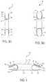
- FIGS. 3 a -3 dare perspective views of an exemplary medical device of FIG. 1 in accordance with some embodiments of the present teachings;
- FIG. 4is a perspective view of the exemplary medical device of FIG. 1 in accordance with some embodiments of the present teachings
- FIG. 5 a - 5 bare perspective views of an exemplary medical device of FIG. 1 in accordance with some embodiments of the present teachings;
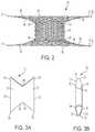
- FIG. 6is exemplary view of a braided structure accordance with some embodiments of the present teachings.
- FIG. 7is an illustration of the relationship between a ratio of flange to shunt diameter versus braid angle of the shunt portion of an exemplary medical device in accordance with some embodiments of the present teachings
- FIG. 8is a perspective view of an exemplary medical device in accordance with some embodiments of the present teachings.
- FIG. 9is a perspective view of an exemplary medical device in accordance with some embodiments of the present teachings.
- FIG. 10is a perspective view of the exemplary medical device of FIG. 8 in a constrained configuration
- FIG. 11is a perspective view of an exemplary medical device in accordance with some embodiments of the present teachings.
- FIG. 12is a perspective view of the exemplary medical device of 11 in a constrained configuration
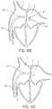
- FIG. 13is a perspective view of the exemplary medical device of FIG. 1 deployed at a target site between left and right atrium of the heart in accordance with some embodiments of the present teachings;
- FIGS. 14 a -14 eare perspective views demonstrating an exemplary process for deploying a medical device in accordance with some embodiments of the present teachings
- FIG. 15is a perspective view of the exemplary medical device of FIG. 5 deployed at a target site between left and right atrium of the heart in accordance with some embodiments of the present teachings;
- FIGS. 16 a -16 eare perspective views demonstrating an exemplary process for retrieving a medical device in accordance with some embodiments of the present teachings
- FIG. 17is a perspective view of an exemplary device of the present teachings in its elongated configuration in accordance with some embodiments of the present teachings;
- FIG. 18is a perspective view of an exemplary device of the present teachings in its expanded configuration in accordance with some embodiments of the present teachings;
- FIGS. 19 a and 19 bare perspective view of two exemplary devices of the present teachings in their respective expanded configurations viewing from their proximal sides in accordance with some embodiments of the preset teachings;
- FIG. 20is a perspective view of an exemplary device of the present teachings in its elongated configuration in accordance with some embodiments of the present teachings;
- FIG. 21is a perspective view of an exemplary device of the present teachings in its expanded configuration in accordance with some embodiments of the present teachings;
- FIG. 22is a perspective view of an exemplary device of the present teachings in its elongated configuration in accordance with some embodiments of the present teachings;
- FIG. 23is a perspective view of an exemplary device of the present teachings in its expanded configuration in accordance with some embodiments of the present teachings.
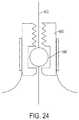
- FIG. 24is a perspective view of an exemplary constraint in accordance with some embodiments of the present teachings.
- the medical devicecan be used to regulate the pressure in a heart chamber.
- the medical devicecan be used to (a) change an elevated chamber pressure and/or (b) prevent embolization from the right to left atria in a patient who suffers from CHF or has a Patent Foramen Ovale (PRO) or an Atrial Septal Defect (ASD) but needs a residual flow between the atria so as not to traumatize the heart hemodynamics.
- PROPatent Foramen Ovale
- ASDAtrial Septal Defect
- proximalshall mean close to the operator (less into the body) and “distal” shall mean remote from the operator (further into the body). In positioning a medical device from a downstream access point, distal is more upstream and proximal is more downstream.
- axial constraining wiremeans a member which can take forms of a suture, cable, wire, or any other small diameter, flexible, semi-rigid or rigid material having a suitable tensile strength for the intended use.
- wirecan be a strand, a cord, a fiber, a yarn, a filament, a cable, a thread, or the like, and these terms may be used interchangeably.
- sutureused herein can be a strand, a wire, a cord, a fiber, a yarn, a filament, a cable, as thread, or the like, and these terms may be used interchangeably.
- a medical deviceincludes a shunt portion.
- the shunt portionis coupled with two retention flanges.
- as medical deviceis positioned through an aperture in a septum.
- a medical deviceis used to create a shunt, for example, between the left and right atria.
- the two retention flanges of the medical devicewhen deployed, are disposed on the opposite sides of the septum.
- a medical devicetransitions into an elongated profile for a percutaneous delivery and resumes its radially expanded profile in vivo after deployment.
- the term “aperture”refers to any anatomical anomalies such as PFO, ASD, VSD, or an anatomical feature created for the purpose of creating a shunt.
- An embodiment of the device in the present teachingshas a distal retention flange. In some embodiments, the distal retention flange is configured to be positioned at the left atrial side of the septum. An embodiment of the device includes a proximal retention flange. In some embodiments, the proximal retention flange is configured to be positioned at the right atrial side of the septum. An embodiment of the device includes a central shunt portion. In some embodiments, the central shunt portion is between of the distal and proximal flanges. In some embodiments, the central shunt portion is configured to create a conduit for blood to flow through. An embodiment of the device in the present teachings has an elongated profile for delivering through a catheter system.
- the elongated profilesometimes includes a delivery profile.
- An embodiment of the device in the present teachingshas an expanded profile for securing the device across the septum.
- the expanded profilesometimes includes a deployed profile.
- a deviceis configured to transits from its delivery profile to its deployed profile. In certain embodiments, this transition is through self-expansion. In certain embodiments, this transition is achieved with a mechanical actuation.
- both distal and proximal retention portions of the deviceexpand radially while contracts longitudinally.
- the central shunt portionalso expands radially while contracts longitudinally.
- the deployed distal and proximal portionshave a general disc like profile which are configured to be positioned at each side of the atrial septum.
- one or both of the deployed distal and proximal flangesare designed to be flanking away from the atrial septum.
- one or both of the deployed distal and proximal flangesare configured to contact and/or compress against the atrial septum.
- the deviceis secured to the treatment location across the atrial septum by one or both of the distal and proximal retention flanges.
- the deviceis secured to the treatment location by the radial expansion of the central shunt portion of the device inside the aperture.
- FIG. 1illustrates an embodiment of the device ( 10 ) in an elongated delivery profile.
- FIG. 1illustrates the elongated configuration of the device without showing a catheter/sheath, which in various embodiment is used to deliver the device.
- the device ( 10 )is generally straightened and is suitable for being delivered via a delivery system (not shown).
- both the distal and proximal portions ( 20 , 30 ) of the device ( 10 )are radially collapsed (or axially elongated or forming a generally tubular profile).
- the delivery configurationas seen in FIG.
- the central shunt portion ( 40 )also has a generally tubular profile.
- the central shunt portion ( 40 ) of the device ( 10 )is also axially elongated (or radially collapsed).
- the central shunt portion ( 40 ) of the device ( 10 )remains unchanged from its pre-set profile.
- each distal and proximal portions ( 20 , 30 ) of the device ( 10 )has a free end ( 22 , 32 ) and a fixed end ( 24 , 34 ).
- the free end ( 22 ) of the distal portion ( 20 )forms a distal end ( 12 ) of the device ( 10 ).
- the free end ( 32 ) of the proximal portion ( 30 )forms a proximal end ( 14 ) of the device ( 10 ).
- the central shunt portion ( 40 )is between the distal and proximal portions ( 20 , 30 ) of the device ( 10 ), with the fixed end ( 24 ) of the distal portion ( 20 ) connecting to a first end ( 42 ) of the central shunt portion ( 40 ) and the fixed end ( 34 ) of the proximal portion ( 30 ) connecting to a second end ( 44 ) of the central shunt portion ( 40 ).
- the delivery profile of the device ( 10 )is in a generally tubular profile.
- the deviceincludes a longitudinal lumen ( 16 ) running from the distal end ( 12 ) of the device to ( 10 ) the proximal end ( 14 ) of the device ( 10 ).
- the longitudinal lumenruns through the elongated distal portion ( 20 ), the central shunt portion ( 40 ), and the proximal portion ( 30 ).
- a delivery catheteris (not shown) fitted inside the longitudinal lumen ( 16 ). This configuration can be used to facilitate a percutaneous delivery of the device ( 10 ) into a heart.
- a delivery catheterengages the proximal end ( 14 ) of the device ( 10 ).
- the axial length of the device ( 10 ) in its delivery profileis 10-200 mm. In certain embodiments, the axial length of the device ( 10 ) in its delivery profile is 1-5 times of that in its deployed profile. In some embodiments, the overall cross sectional size of the device ( 10 ) in its delivery profile is 1-6 mm in diameter. In certain embodiments, the device is disposed in a 3-18 French-size catheter.
- the shunt portion ( 40 ) of the device ( 10 )in its delivery configuration, such as illustrated in FIG. 1 , has a generally uniform cross section with a diameter ranging from about 1 mm to about 10 mm.
- the elongated distal and/or proximal portions ( 20 , 30 )also have a generally uniform cross section profile with a diameter ranging from about 1 mm to about 10 mm.
- the shunt portion ( 40 ) of the device ( 10 )has a length of 1-50 mm.
- the overall elongated device ( 10 )has a length of 10-150 mm.
- FIG. 1illustrates that, according to some embodiments, in the delivery configuration, each of the shunt portion ( 40 ), the elongated distal portion ( 20 ), and the elongated proximal portion ( 30 ) of the device ( 10 ) has a generally uniform cross sectional profile
- the cross sectional profile of each of the distal portion ( 20 ), the proximal portion ( 30 ), and the shunt portion ( 40 )can be different from one another, and/or the cross sectional profile can vary from one part to another even within the same portion (e.g., the distal portion ( 20 ), the proximal portion ( 30 ), or the shunt portion ( 40 )).
- FIG. 2illustrates one embodiment of the device ( 10 ) in present teaching in a radially expanded or deployed profile. As illustrated in FIG. 2 , both the distal ( 20 ) and proximal ( 30 ) portions of the device ( 10 ) are radially extended (sometimes described as axially shortened or forming a generally disc shape) ( 21 , 31 ).
- the inner tubular surface ( 28 ) of the elongated distal portion ( 20 ) at the delivery profiletransitions to form a surface of the distal retention flanges ( 21 ) facing away from the shunt portion ( 40 ) of the device, and facing away from the atrial septum when deployed at treatment location.
- the inner tubular surface ( 38 ) of the elongated proximal portion ( 30 ) at the delivery profiletransitions to form a surface of the proximal retention flange ( 31 ) facing away from the shunt portion ( 40 ) of the device, and facing away from the atrial septum when deployed at treatment location.
- the outer tubular surface ( 26 ) of the elongated distal portion ( 20 ) at the delivery profiletransitions to form a surface of the distal retention flange ( 21 ) facing toward the shunt portion ( 40 ) of the device ( 10 ), and facing toward the atrial septum when deployed at treatment location.
- the outer tubular surface ( 36 ) of the elongated proximal portion ( 30 ) at the delivery profiletransitions to form a surface of the proximal retention flange ( 31 ) facing toward the shunt portion ( 40 ) of the device ( 10 ), and facing toward the atrial septum when deployed at treatment location.
- the free end ( 22 ) of the distal portion ( 20 )transitions radially outward to form the radial outward edge ( 23 ) of the distal flanges ( 21 ); and as the proximal portion ( 30 ) of the device ( 10 ) transitions from its delivery profile to its deployed profile, the free end ( 32 ) of the proximal portion ( 30 ) transitions radially outward to form the radial outward edge ( 33 ) of the proximal retention flange ( 31 ). As illustrated in FIG.
- the distal retention flange ( 21 )has a generally disc-like profile with the free end ( 22 ) of the distal portion ( 20 ) forming the radial outward edge ( 23 ) of the retention flange ( 21 ): and/or the proximal retention flange ( 31 ) has a generally disc-like profile with the free end ( 32 ) of the proximal portion ( 30 ) forming the radial outward edge ( 33 ) of the retention flange ( 31 ).
- the axial lengths of the distal and proximal portions ( 20 , 30 )reduce, and the axial distances between the free ends ( 22 , 32 ) and fixed ends ( 24 , 34 ) of the distal and proximal portions ( 20 , 30 ) of the device ( 10 ) reduces, sometimes significantly, as illustrated.
- the free end ( 22 ) of the distal portion ( 20 )remains distal to the fixed end ( 24 ) of the distal portion ( 20 ) of the device ( 10 ) as illustrated in FIG. 2 and/or FIG. 3 a .
- the free end ( 32 ) of the proximal portion ( 30 )remains proximal to the fixed end ( 34 ) of the proximal portion ( 30 ) of the device ( 10 ) as illustrated in FIG. 2 and/or FIG. 3 a .
- the distal and/or proximal retention flanges ( 21 , 31 )flank away from the atrial septum with the radially outward edges ( 23 , 33 ) of the retention flanges ( 21 , 31 ) not contacting the atrial septum.
- at least one of the distal and/or proximal retention flanges ( 21 , 31 )has a generally cone-shaped profile, a funnel-shaped profile, a hopper-like profile, and the like.
- One ordinarily skilled in the artwould understand that other suitable profiles could also be used.
- the free end ( 22 ) of the distal portion ( 20 )remains proximal to the fixed end ( 24 ) of the distal portion ( 20 ) of the device ( 10 ) as illustrated in FIG. 3 b .
- the free end ( 32 ) of the proximal portion ( 30 )remains distal to the fixed end ( 34 ) of the proximal portion ( 30 ) of the device ( 10 ) as illustrated in FIG. 3 b .
- the distal and/or proximal retention flanges ( 21 , 31 )can have various profiles, including a generally straight slope profile, and a curved umbrella-shaped profile from the fixed ends ( 24 , 34 ) to the free ends ( 22 , 32 ).
- a generally straight slope profilecan be used.
- a curved umbrella-shaped profilefrom the fixed ends ( 24 , 34 ) to the free ends ( 22 , 32 ).
- One ordinarily skilled in the artwould understand that other suitable profiles could also be used.
- At least one of the free ends ( 22 ) of the distal and proximal portions ( 20 , 30 )remains substantially at the same axial location as the fixed ends ( 24 , 34 ) of the corresponding distal portion or proximal portion ( 20 , 30 ) of the device ( 10 ), as illustrated in FIG. 3 c.
- at least one of the distal retention flange ( 21 ) and the proximal retention flange ( 31 )is relatively flat and in the shape of a disc, as illustrated in FIG. 3 c. When deployed at a treatment location, a substantial part of the surface area of the retention discs ( 21 , 31 ) contacts the atrial septum.
- At least one of the distal retention flange ( 21 ) and the proximal retention flange ( 31 )is in the shape of an umbrella with the flange surface doming away from the atrial septum when deployed at a treatment location.
- at least one of the radially outward edges ( 23 , 33 ) of the retention flanges ( 21 , 31 ) of the device ( 10 )contacts the atrial septum and provides additional support in keeping the device in place, as illustrated in FIG. 3 d.
- distal and/proximal retention flanges ( 21 , 31 )can have other shapes or profiles.
- a deployed devicehas its free end ( 32 ) of the proximal portion ( 30 ) proximal to the fixed end ( 34 ) of the proximal portion ( 30 ) of the device ( 10 ), for example, as illustrated in FIG. 3 a , the proximal retention flange of the device flanks away from the atrial septum.
- a deployed devicehas its free end ( 32 ) of the proximal portion ( 30 ) distal to the fixed end ( 34 ) of the proximal portion ( 30 ) of the device ( 10 ), for example, as illustrated in FIG. 3 b , the free end of the proximal portion of the device contacts the atrial septum.
- a deployed devicehas its free end ( 32 ) of the proximal portion ( 30 ) remaining axially the same position as, while radially outward from, the fixed end ( 34 ) of the proximal portion ( 30 ) of the device ( 10 ), for example as illustrated in FIGS. 3 c - 3 d, the free end ( 32 ) of the proximal portion ( 20 ) or/and a substantial surface area of the proximal retention flange ( 31 ) contacts the atrial septum.
- each of the distal and proximal flanges ( 21 , 31 )can adopt any one of the configurations described above.
- the distal and proximal retention flanges ( 21 , 31 )have a same shape and/or configuration, as illustrated in FIGS. 3 a - 3 d.
- the distal and proximal retention flanges ( 21 , 31 )have different shapes and configurations.
- the specific embodiment illustrated or/and described hereinshall not be viewed as limiting.
- FIG. 4illustrates another embodiment of the present teachings, where the proximal portion ( 130 ) of the device ( 100 ) expands and/or folds as the device transitions from delivery configuration to deployed configuration.
- the outer tubular surface of a first section ( 150 ) of the elongated proximal portion ( 130 ) in its delivery profileforms a first surface of ( 152 ) the device ( 100 )
- the first surface ( 152 )faces away from the shunt portion ( 140 ) of the device ( 100 ) and away from the atrial septum when deployed at a treatment location.
- the outer tubular surface of a second section ( 160 ) of the elongated proximal portion ( 130 ) in its delivery profileforms a second surface ( 162 ) of the device ( 100 ).
- the second surface ( 162 )faces toward the shunt potion ( 140 ) of the device ( 100 ) and toward the atrial septum when deployed at treatment location.
- the segment of the proximal portion ( 130 ) of the device ( 100 ) between the first and second sections ( 150 , 160 ) of the elongated proximal portion of the device ( 100 )forms a most radially outward edge ( 133 ) of the proximal retention flange ( 131 ) as shown in FIG. 4 .
- the general diameter of the proximal portion ( 130 ) of the deviceenlarges.
- the axial length of the proximal portion ( 130 )reduces.
- the distance between the free end ( 132 ) and fixed end ( 134 ) of the proximal portion ( 130 ) of the device ( 100 )reduces significantly as illustrated.
- the radially outward edge ( 133 ) of the deployed proximal flange ( 131 )is proximal to the fixed end ( 134 ) of the proximal portion ( 130 ) of the device ( 100 ). Consequently, when the device ( 100 ), in this particular embodiment, is deployed at a treatment location, the radially outward edge ( 133 ) of the proximal retention flange ( 130 ) flanks away from the atrial septum. In certain embodiments, the radially outward edge ( 133 ) of the retention flange ( 131 ) does not contact the atrial septum. Similar to what has been described herein, in some embodiments, the proximal retention flange ( 131 ) has a generally cone-shaped profile, a generally funnel-shaped profile, a generally hopper-like profile or the like.
- the radially outward edge ( 133 ) of the deployed proximal flange ( 140 )is distal to the fixed end ( 134 ) of the proximal portion ( 130 ) of the device ( 100 ). Consequently, when the device, in these particular embodiments, is deployed at a treatment location, the radially outward edge ( 133 ) of the proximal flange ( 131 ) contacts the atrial septum. In certain embodiments, the radially outward edge provides additional support to secure the device ( 100 ) at the treatment location.
- the proximal retention flange ( 131 )has a generally straight-sloped profile, a curved umbrella-shaped profile (for example, from the fixed end ( 134 ) to the free end ( 132 )), or the like.
- the radially outward edge ( 133 ) of the proximal retention flange ( 131 )remains axially at the same position as, while radially outward from, the fixed end ( 134 ) of the proximal portion ( 130 ) of the device ( 100 ).
- the proximal retention flange ( 131 )is relatively flat and, in certain embodiments, in the shape of a disc, for example as illustrated in 5 b. And when deployed at a treatment location, in some embodiments, a substantial surface area of the retention flange ( 131 ) contacts the atrial septum.
- the proximal retention flange ( 131 )has a shape of an umbrella with the flange surfaces doming away from the atrial septum when deployed at a treatment location.
- the radially outward edge ( 133 ) of the proximal retention flange ( 131 ) of the device ( 100 )contacts the atrial septum.
- the radially outward edge ( 133 )provides additional support to secure the device ( 100 ) at the treatment location.
- FIGS. 4-5illustrate and disclose certain embodiments of the proximal retention flange ( 131 ), the illustration and disclosure can also apply to the distal retention flange ( 121 ) of the device ( 100 ). Additionally, the distal retention flange ( 121 ), the proximal retention flange ( 131 ), or both can incorporate any embodiments, described herein and/or illustrated in FIGS. 2-5 . And in some embodiments, the proximal and distal retention flanges ( 121 , 131 ) have a same shape or/and profile. In other embodiments, the proximal and distal flanges ( 121 , 131 ) have different shapes or/and profiles.
- the radial span of the distal and proximal retention flanges ( 21 , 31 , 121 , 131 )is minimized as much as possible in the device.
- the distal and proximal retention flanges ( 21 , 31 , 121 , 131 )have a same size.
- a distal retention flange ( 21 , 121 )is slightly larger than a proximal retention flange ( 31 , 131 ). This can be used to account for the typical left-to-right trans-atrial pressure gradient or/and to facilitate deployment.
- a distal retention flange ( 21 , 121 )has a diameter of 8-40 mm upon deployment.
- a proximal retention flanges ( 31 , 131 )has a diameter of 7-38 mm upon deployment.
- distal and proximal flanges( 21 , 31 , 121 , 131 ) of various sizes, shapes, or/and profiles can be combined to accomplish the goal of securing the device ( 10 , 100 ) in a treatment location, as well as lowering the risk of the device impinging on adjacent cardiac structures.
- the distal and proximal retention flangeswhen deployed at a treatment location, are configured to apply compression force against the respective sides of the atrial septum either along their radially outer edges ( 23 , 33 , 123 , 133 ) or throughout the entire flange surface. In some embodiments, when deployed at a treatment location, the distal and proximal retention flanges ( 21 , 31 , 121 , 131 ) are configured to be in contact with the respective sides of the atrial septum.
- the distal and proximal retention flanges ( 21 , 31 , 121 , 131 )when deployed at a treatment location, are configured not to compress the respective sides of the atrial septum. In some embodiments, when deployed at a treatment location, the distal and proximal retention flanges ( 21 , 31 , 121 , 131 ) are configured not to be in contact with the atrial septum.
- the shunt portion ( 40 , 140 ) between the distal and proximal retention flanges ( 21 , 31 , 121 , 131 )also has a generally tubular shape in its deployed configuration.
- the shunt portion ( 40 , 140 )radially expands during deployment.
- the shunt portion ( 40 , 140 )axially contracts during deployment.
- the shunt portion ( 40 , 140 )remains unchanged geometrically during deployment.
- the shunt portion ( 40 , 140 ) of the device ( 10 , 100 )is configured to be positioned through an aperture across the atrial septum.
- the shunt portion ( 40 , 140 )upon deployment, is configured to be larger than the size of the aperture. In certain embodiments, upon deployment, the shunt portion ( 40 , 140 ) applies a compression force along its outside tubular surface toward the surrounding tissues. Doing so, in certain embodiments, the device ( 10 , 100 ) is secured at the treatment location. In another embodiment, upon deployment, the shunt portion ( 40 , 140 ) has a same size as or is slightly smaller than the size of the aperture. When deployed inside the aperture, the shunt portion ( 40 , 140 ) contacts, without applying additional forces to, the surrounding tissues.
- the cross section of the shunt portion ( 40 , 140 )when the device (( 10 , 100 ) is fully deployed, the cross section of the shunt portion ( 40 , 140 ) has a diameter ranging from about 5 mm to about 30 mm. In some embodiments, the distal and/or proximal retention flanges ( 21 , 31 , 121 , 131 ) have a diameter ranging from about 7 mm to about 40 mm. In some embodiments, when the device ( 10 , 100 ) is fully deployed, the length of the shunt portion ( 40 , 140 ) of a deployed device ranges from about 1 mm to about 30 mm. In some embodiments, the overall length of a deployed device, including the distal, shunt, and proximal portions, ranges from about 1 mm to about 40 mm.
- the shunt portion ( 40 , 140 )has a generally tubular shape.
- a cross section of the shunt portion ( 40 , 140 ) of the deviceis circular or polygonal.
- a cross section of the shunt portion ( 40 , 140 ) of the deviceis square or hexagonal.
- an atrial shunt device( 10 , 100 ) with a braided structure.
- the devicehas a generally braided structure, produced by intertwining a plurality of strands diagonally such that a group of the strands pass alternately over and under another group of strands in the opposite direction.
- the strandsare braided over a mandrel.
- the mandrelis not rotated, while the strand carriers, which are mounted on a wheel normally to the mandrel axis, rotate around the mandrel axis.
- interlacing patternssuch as plain, twill, panama weave, etc.
- a braiding patterninfluences the order of interlacing points in the braided. Accordingly, various braid patterns provide different mechanical properties for the corresponding braided structures.
- the strandsare laser welded at certain locations. In certain embodiments, this is done for the shape-forming purpose. In some embodiments, the strands are laser welded at certain intersections. In certain embodiments, strands at some of the intersections at the shunt portion ( 40 , 140 ) of the device ( 10 , 100 ) are laser welded. Welding at such intersections sometimes increases the stiffness of the shunt portion ( 40 , 140 ). In certain embodiments, strands at some of the intersections within the shunt portion ( 40 , 140 ) of the device ( 10 , 100 ) are laser welded. In particular embodiments, welding at such intersections provides the shunt portion ( 40 , 140 ) with greater stiffness.
- a braid angle “ ⁇ ”is defined, as illustrated in FIG. 6 , as half of the angle of the interlacing between the two nonparallel sets of strands in a braid.
- a braid angle “ ⁇ ”is also defined as the angle between a strand of wire and the machine axis.
- the braid angle “ ⁇ ” of the devicevaries at various portions of the device.
- the proximal retention flange ( 31 , 131 ) of a fully deployed device ( 10 , 100 )has a first braid angle.
- the fully deployed shunt portion ( 40 , 140 ) of a device ( 10 , 100 )has a second braid angle.
- the distal retention flange ( 21 , 121 ) of a fully deployed device ( 10 , 100 )has a third braid angle.
- the second braid angleis greater than the first braid angle or/and the third braid angle.
- the second braid angleis smaller than the first braid angle or/and the third braid angle.
- the first and third braid anglesare the same. In some embodiments, the first and third braid angles are different. According to some embodiments of the present teachings, the braid angle at the shunt portion ( 40 , 140 ) of the device ( 10 , 100 ) is greater than 30 degrees.
- FIG. 7illustrates a relationship between the ratios of a flange diameter to a shunt diameter in a device v. the braid angles of the shunt portion ( 40 , 140 ) of the device.
- the curved line on the graphis defined as 1/sin ⁇
- the ratio of flange/shunt diameterremains on or above the curve in FIG. 7 . That is, the ratio of flange/shunt diameter equals or greater than 1/sin ⁇ .
- the shunt portion ( 40 , 140 )assumes a braid angle of 60 degree and the diameter of the distal and/or proximal flange ( 21 , 121 , 31 , 131 ) is at least 1.2 times of that of the shunt portion ( 40 , 140 ).
- the shunt portion ( 40 , 140 ) of a deployed device ( 10 , 100 )is configured to have a greater hoop stiffness than the distal or/and proximal retention flanges ( 21 , 121 , 31 , 131 ) of the deployed device ( 10 , 100 ) is.
- the shunt portion ( 40 , 140 ) of a deployed device ( 10 , 100 )has a similar hoop stiffness as the distal or/and proximal retention flanges ( 21 , 121 , 31 , 131 ) of the deployed device ( 10 , 100 ).
- the shunt portion ( 40 , 140 ) of the device ( 10 , 100 )when the device ( 10 , 100 ) is deployed at a treatment location, as the shunt portion ( 40 , 140 ) of the device ( 10 , 100 ) resumes its pre-set deployed configuration, the shunt portion ( 40 , 140 ) of the device ( 10 , 100 ) gains a greater hoop stiffness so that it pushes tissues at the aperture radially outwardly and enlarges the opening without the need of a prior dilation of the aperture before deploying the device ( 10 , 100 ).
- a greater hoop stiffness of the shunt portion ( 40 , 140 ) of the device ( 10 , 100 )is also important for maintaining a more consistent shunt sizing regardless of the anatomic character or/and in-growth of atrial septum tissues.
- the braid anglechanges as the device ( 10 , 100 ) transitions from its elongated (delivery) profile to its expanded (deployed) profile.
- the braid angle in the distal portion ( 20 , 120 ) of the device ( 10 , 100 )increases as said portion of the device ( 10 , 100 ) expands radially and contracts longitudinally.
- the braid angle in the proximal portion ( 30 , 130 ) of the device ( 10 , 100 )increases as said portion of the device ( 10 , 100 ) expands radially and contracts longitudinally.
- the braid angle of the shunt portion ( 40 , 140 )also increases.
- the shunt portion ( 40 , 140 ) of the device ( 10 , 100 )remains the same from the delivery profile to the deployed profile.
- the braid angle of the shunt portion ( 40 , 140 )remains constant during the deployment.
- the braid angle of each of the distal portion ( 20 , 120 ), the shunt portion ( 40 , 140 ), and the proximal portion ( 30 , 130 ) of the device ( 10 , 100 )increases.
- the braid angle of each of the distal, shunt, and proximal portionsincreases.
- the braid angle of each of these portionsreaches their pre-set maximum value.
- At least one of the braid angles of the distal portion ( 20 , 120 ), shunt portion ( 40 , 140 ), and proximal portion ( 30 , 130 )changes from 2 to 80 degrees as the device ( 10 , 100 ) transitions from its elongated delivery profile to its expanded deployed profile.
- the extents of the braid angle changes during the delivery-to-deployed profile transitionare the same for each portion of the device ( 10 , 100 ).
- the extents of the braid angles changes during the delivery-to-deployed profile transitionare different for one portion of the device ( 10 , 100 ) to another.
- the extent of the braid angle change for the distal portion ( 20 , 120 )is greater than that of the braid angle change for the shunt portion ( 40 , 140 ). In yet other embodiments, the extent of the braid angle change for the distal portion ( 20 , 120 ) is lesser than that of the braid angle change for the shunt portion ( 40 , 140 ). In some embodiments, the extent of the braid angle change for the proximal portion ( 30 , 130 ) is greater than that of the braid angle change for the shunt portion ( 40 , 140 ). In yet other embodiments, the extent of the braid angle change for the proximal portion ( 30 , 130 ) is lesser than that of the braid angle change for the shunt portion ( 40 , 140 ).
- the braid angleis controlled by adjusting the number of carriers, the speed in which the carrier travels, and the feed rate of the mandrel through the braider.
- the braid angle changecan also be achieved by braiding strands on a shaped mandrel. Additionally, strands can be bent in order to achieve acute changes in the braid angle, for example, at places where the distal portion ( 20 , 120 ) changes into the shunt portion ( 40 , 140 ) of the device, or the place where the proximal portion ( 30 , 130 ) changes into shunt portion ( 40 , 140 ) of the device ( 10 , 100 ).
- a braid strand densitydetermines the mesh site for a deployed device ( 10 , 100 ).
- the braid strand density for a device of the present teachingsis 10-120 PPI during a braiding process.
- both the distal and proximal flanges ( 21 , 121 , 31 , 131 )form open mesh-like surface structures.
- each mesh openinghas a cross-sectional area from about 1 mm 2 to about 5 mm 2 .
- the accumulated area of the openings in the mesh-like surface structure on the entire device ( 10 , 100 )is about 50-95% of the entire surface area of the device ( 10 , 100 ).
- the distal and/or proximal retention flanges ( 21 , 121 , 31 , 131 )have a uniform braid angle throughout its/their planary surface. According to some embodiments, the distal and/or proximal retention flanges ( 21 , 121 , 31 , 131 ) have a uniform braid wire density throughout its/their planary surface. According to some embodiments, the distal and/or proximal retention flanges ( 21 , 121 , 31 , 131 ) have an open mesh-like surface structure with a generally uniform size throughout its/their planary surface.
- the braid angle or/and braid wire densitycan vary throughout its/their planary surface to satisfy various purposes of the application.
- the braid wire densitycan be less toward the free end ( 22 , 122 , 32 , 132 ) of the distal/proximal retention flange ( 21 , 121 , 31 , 131 ) and more toward the other end of the flange.
- the free end ( 22 , 122 , 32 , 132 ) of the flanges ( 21 , 121 , 31 , 131 )is more flexible and conforms more readily to the anatomy of the surrounding tissues.
- a greater braid wire densityleads to a smaller sized mesh-like surface structure which, in turn, prevents tissue in-growth and allows the shunt to stay open over a greater time. And as smaller braid wire density leads to a larger sized mesh-like surface structure which, in turn, allows tissue in-growth over the structure and secures the implant in place.
- the braid angleis smaller at the free end ( 22 , 122 , 32 , 132 ) of the retention flange ( 21 , 121 , 31 , 131 ) and greater at the other end of the flange ( 21 , 121 , 31 , 131 ).
- a portion of the distal/proximal retention flanges( 21 , 121 , 31 , 131 ) has a stronger hoop strengths than other portion.
- One skilled in the artwould recognize that the size, shape, braid angle, or/and braid wire density of the distal and proximal retention flanges ( 21 , 121 , 31 , 131 ) can vary along the surface of these portions.
- the shunt portion ( 40 , 140 ) of the device ( 10 , 100 )has a uniform braid angle throughout its tubular surface. In some embodiments, the shunt portion ( 40 , 140 ) of the device ( 10 , 100 ) has a uniform braid wire density throughout its tubular surface. In some embodiments, the shunt portion ( 40 , 140 ) of the device ( 10 , 100 ) has a mesh-like surface structure with a generally uniform size. Similar to what's has been described here, the braid angle and braid wire density can vary, for example, to satisfy various purposes. One skilled in the art would recognize that the size, shape, braid angle, or/and braid wire density of the shunt portion ( 40 , 140 ) of the device ( 10 , 100 ) can vary along the surface of shunt portion ( 40 , 140 ).
- the device ( 10 , 100 )is manufactured by braiding the distal, shunt, and proximal portions ( 20 , 120 , 40 , 140 , 30 , 130 ) together as a unity.
- the deviceis manufactured by braiding the distal, shunt, and proximal portions ( 20 , 120 , 40 , 140 , 30 , 130 ) separately and joining the portions together after braiding.
- At least one of the distal and proximal retention flanges ( 21 , 121 , 31 , 131 ) and shunt portion ( 40 , 140 )is made of a biocompatible metal or polymer.
- the entire device ( 10 , 100 )is made of a biocompatible metal or polymer.
- the device ( 10 , 100 ) in its entirely or the portion(s) with curved/bent deployment configurationis made of an elastic material, a super-elastic material, or a shape-memory alloy which allows the above portions to be distorted into a generally straightened profile during the delivery process and resume and maintain its intended profile in vivo after it is deployed from a delivery catheter.
- the device ( 10 , 100 )is made of stainless steel, nitinol, Titanium, Elgiloy, Vitalium, Mobilium, Ticonium, Platinore, Stellite, Tantalum, Platium, Hastelloy, CoCrNi alloys (e.g., trade name Phynox), MP35N, CoCrMo alloys, any other metallic alloys, or a mixture thereof.
- a part of the device ( 10 , 100 ) or the entire deviceis made of a polymer, such as PTFE, UHMPE, HDPE, polypropylene, polysulfone, or other biocompatible plastic.
- the surface finish of the device ( 10 , 100 )can be textured to induce tissue response and tissue in-growth for improved stabilization.
- a part of or all the device ( 10 , 100 )can be fabricated from a resorbable polymer such as polyactic acid, polyglycolic acid, polycaprolactone, a combination of two or more of the above or a variety of other resorbable polymers that are well known to those skilled in the art.
- the device ( 10 , 100 )is constructed from metallic strands.
- strandused herein can be wires, cords, fibers, yarns, filaments, cables, threads, or the like, and these terms may be used interchangeably.
- the wire used to form the device ( 10 , 100 )has a general diameter from about 0.02 mm to about 1 mm.
- a braided device ( 10 , 100 ) of the present teachingsincludes 6-48 wires.
- the braided device ( 10 , 100 )includes 3-24 folded wires as starting at one end of the device ( 10 , 100 ) and braiding toward the other end of the device. Each end of the folded strand is braided in the opposite helical directions.
- the braided device ( 10 , 100 )is formed from a single strand that is helically wound from one end of the device ( 10 , 100 ) to the other end of the device ( 10 , 100 ).
- the strandUpon reaching to the end of the device ( 10 , 100 ), the strand is bent and wound in the opposite helical direction while passing alternately over and under the previously formed helical windings to form a braided structure.
- the number of passes of the strand from one end of the device ( 10 , 100 ) to the othermay be adjusted in conjunction with the braid angle to form a desired strand mesh density.
- One skilled in the artwould understand that more or less wires can be used to form the braid structure of the device ( 10 , 100 ).
- the ends of the strandsare bent, braided, or otherwise tugged back toward the opposite end of the device ( 10 , 100 ) and into the braid intersections so that the braided structure does not unwind itself.
- at least some of the loose ends of the wireare optionally laser welded, crimped, or constrained by a sleeve to the adjacent wire.
- the device ( 10 , 100 )is braided from strands each of which has a diameter that varies along its length.
- a strand with a varying diameteris used such that the shunt portion ( 40 , 140 ) of the device ( 10 , 100 ) is braided with a section of the strand that has a larger diameter while the distal and proximal flanges ( 21 , 121 , 31 , 131 ) are braided with sections of the same strands that have smaller diameters.
- Thisprovides a device ( 10 , 100 ) with a sufficiently stiff central shunt ( 40 , 140 ) and relatively flexible (compliant) distal and proximal flanges ( 21 , 121 , 31 , 131 ).
- Strands of varying diametermay be formed by a variable drawing process. Various combinations of diameter may be used along the length of the strand to impart sufficient stiffness and compliance where it is needed.
- the device ( 10 , 100 )is braided into a tubular form and then shaped to its final configuration.
- a sufficiently elastic and resilient materialsuch as nitinol
- the structureis preformed into the finished shape and then elastically deformed and stowed for the delivery.
- the device ( 10 , 100 )elastically recovers to its pre-formed shape.
- the shunt portion ( 40 , 140 ), the distal portion ( 20 , 120 ), or/and the proximal portion ( 30 , 130 )are manually expanded to desired diameters.
- the shunt portion ( 40 , 140 ), the distal portion ( 20 , 120 ), or/and the proximal portion ( 30 , 130 )is/are curved to a pre-set shape and heat set in an oven while constrained to the desired shape.
- heat settingis incorporated before, during, or after the wire is braided on the mandrel.
- the pre-setting or/and heat settingcan be used to control the superelasticity of the nitinol wire and set the final shape of the device ( 10 , 100 ), including the size and shape of the two retention disks and the outer diameter of the shunt portion ( 40 , 140 ) of the device ( 10 , 100 ).
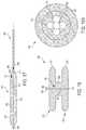
- FIGS. 8-9illustrate an exemplary retrievable atrial shunt device ( 200 , 300 ) in its deployed configuration. Similar to embodiments described herein in relationship to FIGS. 1-5 , as illustrated in FIG. 8 , the exemplary atrial shunt device ( 200 ) has a distal retention flange ( 221 ), a proximal retention flange ( 231 ), and a shunt potion ( 240 ).
- the distal retention flange ( 221 ), proximal retention flange ( 231 ), and shunt portion ( 240 ) of the exemplary atrial shunt device ( 200 )are made of a braided structure.
- proximal retention flange ( 231 )is configured to form a releasable attachment between the atrial shunt device ( 200 ) and a delivery system in such way that device ( 200 ) can be reposition and retrieved.
- the exemplary atrial shunt device ( 200 )includes a plurality of proximal struts ( 250 ).
- Each proximal strut ( 250 )has one end ( 252 ) connecting to the free end ( 232 ) of the proximal flange ( 231 ) and a second end ( 254 ) connecting to the second ends of other proximal struts to form a proximal hub ( 260 ).
- the proximal hub ( 260 )is configured to releasably connect the device to a delivery catheter.
- proximal struts ( 250 )illustrates four proximal struts ( 250 ), one skilled in the art would understand that so long as the proximal struts ( 250 ) do not impede blood flow through the shunt device ( 200 ), the number of proximal struts ( 250 ) can be any number between two and ten without any significant changes to the device or methods of making or using thereof described herein.
- all proximal struts ( 250 ) of the device ( 200 )join one another to form a proximal hub ( 260 ).
- proximal hub260
- a first proximal strut ( 350 a )has a first end ( 352 ) connecting to a first place on the free end ( 352 a ) of the proximal retention flange ( 331 ) and a second end ( 354 ) connecting to a second place on the free end ( 332 ) of the proximal retention flange ( 331 );
- a second proximal strut ( 350 b )has a third end connecting to a third place on the free end ( 332 ) of the proximal retention flange ( 331 ) and a fourth end connecting to a fourth place on the free end ( 332 ) of the proximal retention flange ( 331 ); and a third proximal strut ( 350 c ) connects the first ( 350 a ) and second proximal strut ( 350 b ).
- the third proximal strut ( 350 c )is also configured to be connected with a delivery mechanism, for example, by incorporating a proximal hub ( 360 ) or by direct attachment.
- a delivery mechanismfor example, by incorporating a proximal hub ( 360 ) or by direct attachment.
- proximal hub ( 360 )or by direct attachment.
- more than three proximal struts ( 350 a, 350 b, 350 c )can be used to create a similar design so long as the proximal hub ( 360 ) does not impede blood flow.
- each of the proximal struts ( 250 , 350 )is the same size as the braided strand. In other embodiments, the proximal strut ( 250 , 350 ) has a different size from the braided strand. In some embodiments, the proximal struts ( 250 , 350 ) are a same size. In other embodiments, at least one of the struts ( 250 , 350 ) has a size different from at least another proximal struts.
- the exemplary proximal hub ( 260 , 360 ) in these examplesis a circular ring that connects to all of the proximal struts via an end of each of the proximal strut.
- the proximal hub ( 260 , 360 ) of the device ( 200 , 300 )is configured to connect with a delivery catheter.
- the specific design of the proximal hub ( 260 , 360 )can be anything known to those in the field and suitable for connecting to the distal end of a delivery catheter/sheath.
- the proximal hub ( 260 , 360 )has a thread feature which is configured to be threadably connected to a delivery catheter.
- the proximal hub ( 260 , 360 )is configured to join the distal end of a delivery catheter in a pin-through-hole mechanism, a ball-claw mechanism, a groove-collet mechanism, or any other type of interlocking connection.
- connection mechanismscan be used between the proximal hub ( 260 , 360 ) and the delivery catheter.
- FIGS. 8-9illustrate various exemplary retrievable/repositionable atrial shunt devices ( 200 , 300 ) in their deployed configurations.
- the proximal strut ( 250 , 350 )extends proximally from the proximal retention flange ( 231 , 331 ) and forms a general cone shape.
- the proximal struts ( 250 , 350 )extend into the right atrium.
- the proximal struts ( 250 , 350 )are aligned in the same plane as the proximal retention flange ( 231 , 331 ).
- the device ( 200 , 300 )has a generally small profile.
- the deployed proximal struts ( 250 , 350 )also form a filter or flow control element that prevents blood clog from entering the left atrium through the shunt.
- FIG. 10illustrates another embodiment of the present teachings where the retrievable/reposition atrial shunt device ( 200 ) is in its elongated delivery profile.
- the distal retention flange ( 221 )collapses radially and extends axially to form an elongated distal portion ( 220 ) and the proximal retention flange ( 231 ) collapses radially and extends axially to form an elongated proximal portion ( 230 ).
- the shunt portion ( 240 ) of the device ( 200 )also collapses radially and extends axially to form an elongated shunt portion ( 240 ).
- the shunt portion ( 240 ) of the deviceremains the same at the delivery and deployed configurations.
- the proximal struts ( 250 ) of the devicealso collapses radially as the first ends ( 252 ) of the proximal struts ( 250 ) connect with the elongated proximal portion ( 230 ) of the device ( 200 ) and extend axially and the second ends ( 254 ) attaches to a proximal hub ( 260 ), which is configured to attach to the distal end of a delivery catheter (not shown).
- FIG. 11illustrates a prospective view of another embodiment of a retrievable/repositionable device ( 400 ) of the present teachings.
- a strand loop ( 450 )extends through braided strands ( 433 ) at the free end ( 432 ) of the proximal portion ( 430 ) of a device ( 400 ).
- this strand loop ( 450 )threads through all meshes at the free end ( 432 ) of the proximal portion ( 430 ) of the device ( 400 ) and each of the braided mesh is slidable along the strand loop ( 450 ).
- the loop strand ( 450 )is configured to accommodate the size of the free end ( 432 ) of the proximal flange ( 431 ) at its fully deployed configuration.
- the loop stand ( 450 )has a relatively great size.
- the loop stand ( 450 )has a relatively small size.
- FIG. 12illustrates an elongated delivery configuration of the device as shown in FIG. 11 .
- the shunt device ( 400 )is collapsed into an elongated configuration.
- the braided meshes ( 432 )collapse and slide along the proximal loop strand ( 450 ) as the proximal retention flange extends axially.
- the loop stand ( 450 )can further be stretched and configured to be attached to a delivery catheter (not shown).
- At least one of the shunt portion, the distal portion, and the proximal portionexpands radially when the device is deployed in vivo.
- the radial expansion of at least one of the shunt portion, the distal portion, and the proximal portion of the deviceis due to the elastic nature of the material.
- the radial expansion of at least one of the shunt portion, the distal portion, and the proximal portion of the deviceis due to its pre-set shape memory of the material.
- at least one of the shunt portion, the distal portion, and the proximal portion of the deviceis radially expanded via a balloon, sometimes, manually.
- the deviceis generally mounted a balloon catheter and the inflatable balloon is positioned inside the central lumen of the elongated device.
- the inflatable ballooncan be positioned inside at least one of the shunt portion, the distal portion, and the proximal portion.
- the balloonis then inflated and radially expands at least one of the shunt portion, the distal portion, and the proximal portion of the device. Then upon reaching to desired the balloon can then be deflated and retracted out of the device and back into the delivery catheter.
- the inflatable balloonis positioned inside the central lumen of the entire elongated device.
- the deviceis expanded by inflating the balloon.
- radioopaque markersare used. Without attempting to limit to any particular function, these radioopaque markers can be visualized by using radiographic imaging equipments such as X-ray, magnetic resonance, ultrasound or other imaging techniques. Marker as disclosed herein can be applied to any part of a device or a delivery system of the present teachings. A radioopaque marker can be weld, sewed, adhered, swaged riveted, otherwise placed, and secured in or on the device.
- the radioopaque markermay be made of tantalum, tungsten, platinum, irridium, gold, or alloys of these materials or other materials that are known to those skilled in the art.
- the radioopaque markercan also be made of numerous paramagnetic materials, including one or more elements with atomic numbers 21-29, 42, 44, and 58-7 0 , such as chromium (III), manganese (II), iron (III), iron (II), cobalt (II), copper (II), nickel (II), praesodymium (III), neodymium (III), samarium (III), ytterbium (III), gadolinium (III), terbium (III), dysprosium (III), holmium (III) and erbium (III), or other MR visible materials that are known to those skilled in the arts.
- chromium (III)manganese (II), iron (III), iron (II), cobalt (II), copper (II), nickel (II), praesodymium (III), neodymium (III), samarium (III), ytterbium (III), gad
- a device of the present teachingsincludes a flow control element.
- the flow control elementis a tissue valve.
- the flow control elementis as a tricuspid valve, a bicuspid valve, or a single flap valve.
- the flow control elementis a ball valve, a duckbill valve, a leaflet valve, a flap valve, a disc in cage type valve, a ball in cage type valve, or other type of valve known to those skilled in the field.
- the tissue valveis formed from a bio material or a biocompatible synthetic material. In certain embodiments, the biomaterial is pericardial tissues.
- the pericardial tissuesare of the origin of bovine, porcine, ovine or other animal.
- the biocompatible synthetic materialis Dacron, Teflon, polyurethane, PET, or other suitable polymer.
- a flow control element of the present teachingscan be made of any suitable material known in the art.
- the tissue valveis incorporated inside the axial lumen of at least one of the shunt portion, the distal retention flange, and the proximal retention flange of the device. Yet in some other embodiments, the tissue valve is incorporated inside the axial lumen of at least two of the shunt portion, the distal retention flange, and the proximal retention portion of the device. In certain embodiments, the tissue valve is incorporated in the shunt portion and the distal retention flange of the device. In certain embodiments, the tissue valve is incorporated in the shunt portion and proximal retention portion of the device. In yet some other embodiments, the tissue valve is incorporated inside the axial lumen of the entire length of the device. According to some embodiments, the tissue valve is configured to open when the pressure differential reaches a selected value. In some embodiments, the tissue valve remains closed until the pressure differential reaches a selected value.
- various portions of the deviceis configured to have different stiffness/flexibility.
- the distal and proximal retention flangescan be configured to have lesser stiffness than the shunt potion. This way, in many embodiments, inadvertent damages to the septal wall is avoided.
- a shunt portion with a relatively great stiffnessholds the tissue around the aperture open.
- the portion of the retention flanges that contacts the septal tissueis less stiff than another portion of the retention flanges.
- lesser stiffnessgenerally relates greater flexibility and greater stiffness relates lesser flexibility.
- One skilled in the artwould also understand and be capable of constructing various portions of the device with varying stiffness/flexibility so that desired properties for the device can be achieved.
- the stiffness/flexibility for various portions of the deviceis controlled by the choice of a material. In some embodiments, the stiffness/flexibility for various portions of the device is adjusted by to chemical treatment, a physical treatment, or both. In some embodiments, the stiffness/flexibility of various portions of the device is achieved by ways in which each of the various portions is constructed.
- FIG. 13depicts an embodiment of a device of the present teachings deployed across the atrial septum ( 2 ).
- This devicecan be that shown in FIGS. 1 and 2 .
- the distal retention flange ( 21 ) of the device ( 10 )is disposed against the left atrial side of the septal tissue and the proximal retention flange ( 31 ) of the device ( 10 ) is disposed against the right atrial side of the septal tissue.
- the shunt portion ( 40 ) of the device ( 10 )is positioned through the aperture of the septum ( 2 ).
- the shunt portion ( 40 ) of the device in FIG. 13forms a liquid passageway.
- FIGS. 14 a -14 eillustrate exemplary steps for the deployment of an exemplary device ( 10 ) inside a heart according to some embodiments of the present teachings.
- the devicecan be one that is illustrated in FIGS. 1 and 2 .
- an apertureis located before the exemplary device ( 10 ) is introduced into the treatment site.
- a guide wire(not shown) is placed across the aperture.
- the guide wireis used to guide the delivery and deployment of a device of the present teachings.
- a delivery assemblycan be used to deliver and deploy a device without the need of a guidewire.
- the delivery system ( 500 )is inserted percutaneously by a clinician at an insertion point. As depicted in FIG. 14 a , the distal portion ( 502 ) of the delivery system ( 500 ) is advanced percutaneously into the heart and toward the atrial septum ( 2 ). In some embodiments, the delivery system ( 500 ) is advanced into the atrial septum ( 2 ) through a standard right heart catheterization procedure. In such a procedure, a cardiac implant is delivered through the femoral vein, the inferior vena cava, and the right atrium ( 4 ).
- a devicesuch as the one as shown in FIGS. 1-2 , is slidably disposed over a delivery catheter.
- the axial motion of the deviceis controlled by the axial motion of the distal portion of the delivery catheter, which in turn is controlled by a clinician outside of the body.
- the distal end of a delivery catheterengages the proximal hub or proximal strut(s) of the device during delivery.
- the axial motion of the deviceis controlled by the axial motion of the distal portion of the catheter, which in turn is controlled by a clinician outside of the body.
- a delivery sheathslides over the delivery catheter and the elongated device to maintain the device in its elongated delivery profile.
- a radio-opaque markeris used on the delivery sheath, the delivery catheter, or the device to aid a clinician to determine how far the distal portion of the delivery assembly extends inside the left atrium.
- the device ( 100 )is pre-loaded within the distal end portion ( 502 ) of the delivery system ( 500 ) and is carried across the atrial septum ( 2 ) as the delivery system ( 500 ) extends percutaneously.
- the delivery system ( 500 )is positioned across the septum ( 2 ) first and then the device ( 10 ) is pushed from the proximal end (not shown) to the distal end portion ( 502 ) of the delivery system ( 500 ).
- the cliniciancan start to deploy the device ( 10 ).
- the cliniciandeploys the distal portion ( 20 ) of the device ( 10 ) inside the left atrium ( 6 ), as shown in FIG. 14 b .
- the delivery system ( 500 )is retracted proximally to expose the distal portion ( 20 ) of the device ( 10 ).
- the device ( 10 )is deployed by pushing the distal portion ( 20 ) the device ( 10 ) distally out of the distal end portion ( 502 ) of the delivery system ( 500 ).
- distal portion ( 20 ) of the device 10As the distal portion ( 20 ) of the device 10 ) is exposed outside of the delivery system ( 500 ), the distal portion ( 20 ) of the device ( 10 ) expands radially and contracts axially to resume its pre-set deployed configuration and form. a distal retention flange ( 21 ).
- the distal retention flange ( 21 ) of the device ( 10 )is positioned against the left atrial side of the septum ( 2 ).
- the distal retention flange ( 21 ) of the device ( 10 )is pulled against the left atrial side of the septum ( 2 ).
- FIG. 14 dillustrates the deployment of the proximal portion ( 30 ) of an exemplary device ( 10 ) using similar steps as described herein.
- the delivery system ( 500 )is withdrawn proximally to expose the proximal portion ( 30 ) of the device ( 10 ) inside the right atrium ( 4 ).
- the proximal portion ( 30 ) oldie device ( 10 )is exposed, the proximal portion ( 30 ) of the device ( 10 ) expands radially and contracts axially to resume its pre-set deployed configuration.
- the proximal portion ( 30 )forms a proximal retention flange ( 31 ).
- the device ( 10 ) shown in FIGS. 1-2after the proximal retention flange ( 31 ) is fully deployed, the device ( 10 ) is free from the constraint of the delivery system ( 500 ). Accordingly, the delivery system ( 500 ) can then be removed from the body, as shown in FIG. 14 e.
- the proximal end of the device ( 200 )remains engaged with the distal end ( 502 ) of the delivery system ( 500 ), as shown in FIG. 15 .
- a cliniciancan assess the deployment of the device at the treatment location.
- the engagement between the proximal end of the device ( 200 ) and the distal end ( 502 ) of the delivery system ( 500 )can be articulated or pivoted in order to position or adjust the position of the device ( 200 ) prior to releasing. These articulable or pivotable engagements are known to those skilled in the art.
- the device ( 200 )can be retrieved.
- a clinicianpulls the proximal hub ( 260 ) of the device ( 200 ).
- the delivery system ( 500 )is extended distally.
- the distal end portion ( 502 ) of the delivery system ( 500 )slides over the proximal portion ( 230 ) of the device ( 200 ).
- the entire proximal portion ( 230 ) of the device ( 200 )enters the distal end portion ( 502 ) of the delivery system ( 500 ), as shown in FIG. 16 a .
- the entire delivery assembly ( 500 ) including the device ( 200 )can then extend distally into the left atrium ( 6 ), as shown in FIG. 16 b .
- a clinicianfurther pulls the proximal hub ( 260 ) of the device ( 200 ) proximally to collapse the distal retention flange ( 221 ).
- the distal portion ( 220 ) of the device ( 200 )slides into the lumen of the distal end portion ( 502 ) of the delivery system ( 500 ), as shown in FIG. 16 c .
- the entire delivery assembly ( 500 )can be retracted proximally and removed from the patient.
- the device ( 200 )can be redeployed, by following the steps described herein.
- the device ( 200 )upon completing a deployment the device ( 200 ) at a treatment location, if the clinician is satisfied with the deployment, the device ( 200 ) can then be completely released from the delivery system ( 500 ).
- the delivery system ( 500 )can then he withdrawn proximally out of the body.
- FIGS. 17-19illustrate another embodiment of the present teachings.
- FIG. 17illustrates an elongated delivery configuration of a device ( 600 ) and
- FIG. 18illustrates a deployed configuration of the device ( 600 ).
- FIG. 19 a - billustrate a perspective views of the device ( 600 ) in its deployed configuration.
- the device ( 600 ) in these figuresis also made from braiding wire(s) or strand(s) of wires with various braiding angels.
- the device ( 600 )includes a proximal and distal retention flanges ( 631 , 621 ) on each side of a shunt portion ( 640 ).
- the shunt portion ( 640 )has a greater braiding angle than the distal retention flange ( 621 ) or/and the proximal retention flange ( 631 ). This way, the shunt portion ( 640 ) is stiffer than the distal retention flange ( 621 ) or/and the proximal retention flange ( 631 ). In particularly embodiments, the shunt portion ( 640 ) is stiffer axially. As the device ( 600 ) is deployed in situ, the relatively stiffer shunt portion ( 640 ) prevents the device ( 600 ) from collapsing on its own.
- a relatively stiff shunt portion ( 640 )reduce ingrowth of surrounding tissues. Similar to the embodiments disclosed in FIG. 10 , the proximal ends of the braiding wires are secured to a proximal hub which is configured to attach the device to a delivery system.
- the distal portion ( 620 ) of the devicewhen device ( 600 ) is deployed, the distal portion ( 620 ) of the device expands radially and folds approximately along the midline so that the ends of the distal portion get close to each other and the midline of the distal portion forms a radially outward edge ( 623 ).
- the distal ends of the braided wiresare secured together to form a proximal end of the device.
- the proximal portion ( 630 ) of the deviceexpands radially and folds approximately at the midline so that the ends of the proximal portion get close to each other and the midline of the proximal portion forms a radially outward edge ( 633 ).
- the shunt portion ( 640 ) of the devicealso expands radially and shortens longitudinally.
- the braiding wirein order to allow blood to flow through a deployed device, is configured in such way so that upon deployment at least one opening ( 670 ), or hole ( 670 ), is formed in at least one of the distal and/or proximal retention flanges.
- FIGS. 19 a - billustrate two exemplary shapes of the openings ( 670 ) formed by braiding wires in the proximal retention flange ( 631 ).
- the distal retention flangeincludes at least one opening ( 670 ).
- both the proximal retention flange and the distal retention flangeinclude at least one opening ( 670 ).
- the proximal retention flangeincludes one, two, three, four, five, six, or more openings ( 670 ). In certain embodiments, the distal retention flange includes one, two, three, four, five, six, or more openings ( 670 ).
- the proximal retention flangeincludes one, two, three, four, five, six, or more openings ( 670 ).
- the distal flange ( 621 )is positioned against the left atrial side of the septum
- the proximal flange ( 631 )is positioned against the right atrial side of the septum
- the shunt portion ( 640 )is positioned across an aperture in the septum.
- FIGS. 17-24also illustrate another aspect of the present teachings.
- a braided shunt device ( 670 )includes an axial constraining, mechanism ( 680 ).
- the axial constraining mechanism ( 680 )provides additional stiffness to a device ( 600 ) of the present teachings.
- FIG. 18illustrates one exemplary device.
- a deployed braided shunt device ( 600 )has radially expanded, generally disc shaped proximal and distal retention flanges ( 631 , 621 ) at either side of the shunt portion ( 640 ).
- An axial constraining mechanism ( 680 )restrains the axial length of the shunt portion ( 640 ) of a deployed device ( 600 ). As a result, the stiffness of the shunt portion ( 640 ) increases.
- the axial constraining wire ( 682 )has a distal end ( 684 ) connected to the device ( 600 ).
- a proximal end of the axial constraining wire ( 682 )includes a locking feature ( 686 ).
- the locking featureis configured to engage a lock receiver ( 688 ) on the device.
- the distal end ( 684 ) of an axial constraining, wire ( 682 )is connected to a place at or near the distal end of the device ( 600 ).
- the distal end ( 684 ) of the axial constraining wire ( 682 )is fixed to a place at or near the distal end of the shunt portion ( 640 ) or the proximal retention flange ( 631 ) of the device.
- the distal end ( 684 ) of the axial constraining wire ( 682 )can be fixed to a place along the longitudinal body of the shunt portion of the device.
- the axial constraint wire ( 682 )includes a locking feature ( 686 ).
- the locking feature ( 686 )engages a lock receiver ( 688 ) at the proximal hub (not shown) of a deployed device.
- FIG. 21illustrates another embodiment where the locking feature ( 686 ) of the axial constraining wire ( 682 ) engages a lock receiver ( 688 ) at a place on the proximal retention flange ( 631 ).
- the locking feature ( 686 ) of the axial constraining wire ( 682 )engages a strand loop (not shown) at or near the proximal end of the proximal retention flange ( 631 ).
- the locking feature ( 686 ) of the axial constraining wire ( 682 )engages a lock receiver ( 688 ) at a place at or near the proximal end of the shunt portion ( 640 ) of a device ( 600 ).
- a lock receiver ( 688 ) of the deviceis configured to engage the locking feature ( 686 ) of an axial constraining wire ( 682 ).
- the locking feature ( 686 ) of the axial constraining wire ( 682 )enters into a distal end of a lock receiver ( 688 ).
- the lock receiver ( 688 )is configured to prevent the locking feature ( 686 ) from retracting.
- the axial constraining wirehas a locking feature ( 686 ), for example, a ball, and the locking feature is configured to engage a sleeve-like lock receiver ( 688 ). Once engaged, the lock receiver ( 688 ) prevents the axial constraining wire ( 682 ) from being released from the sleeve.
- a locking feature ( 686 ) on an axial constraining wire ( 682 ) and a lock receiver ( 688 )is illustrated in FIG. 24 .
- One skilled in the artwould understand that many suitable lock designs can be incorporated herein to secure the constraining wire upon deployment of a device. Examples such as wire-crimp securement mechanism, thread securement mechanism, etc. can all be incorporated herein.
- an axial constraining mechanism ( 680 )can include an axial constraining wire ( 682 ). While the description herein refers to wires, wires, cables, sutures, or threads are essentially interchangeable. In addition, in some embodiments, each wire, cable, suture, or thread comprises one or more wires, cables, sutures, or threads. According to certain embodiments of the present teachings, the axial constraining wire ( 682 ) is made of a variety of materials, including a metal, an alloy (e.g., a stainless steel or Nitinol), or a plastic.
- FIGS. 17, 20, and 22illustrate the elongated delivery configurations of devices ( 600 ) of the present teachings. In addition, they are shown to be attached to as delivery system ( 690 ).
- a device ( 600 ) of the present teachingsis elongated into a tubular profile and an axial constraining wire ( 682 ) is not engaged to a lock receiver ( 688 ) on the device ( 600 ).
- the axial constraining wire ( 682 )is housed inside the longitudinal body lumen of the elongated device ( 600 ).
- the proximal end ( 614 ) of the device ( 600 )is operably attached to the distal end ( 694 ) of a delivery catheter ( 690 ).
- the proximal end of the axial constraining wire ( 682 )is also operably attached to as distal end ( 694 ) of a delivery cable (not shown).
- the delivery cable (not shown)is slidably disposed within the axial lumen of the delivery catheter ( 690 ).
- the delivery cable (not shown) and delivery catheter ( 690 )move independently.
- the device ( 600 )is deployed at a treatment site, similar to the process described herein, in relation to FIGS. 14-16 . During the percutaneous deployment process, the axial constraining wire ( 682 ) remains attached to the delivery cable (not shown).
- the deployment of the device ( 600 )is facilitated with the proximal pulling of the axial constraining wire ( 682 ). In some embodiments, the deployment of the device ( 600 ) is independent of the movement of the axial constraining wire ( 682 ). In some embodiments, the process of locking the axial constraining wire ( 682 ) by a lock receiver ( 688 ) involves holding the device ( 600 ) while pulling the proximal end of the axial constraining wire ( 682 ) proximally and engaging the locking feature ( 686 ) with the lock receiver ( 688 ) of the device ( 600 ). In some embodiments, the engagement of the axial constraining wire ( 682 ) is the last step of a device deployment.
- the engagement of the axial constraining wire ( 682 )is before the last step of a device deployment. Upon a satisfactory deployment, the axial constraining wire ( 682 ) disengages from the delivery cable (not shown).
- the axial constraining mechanism ( 680 )is made of suture ( 682 ) and the lock receiver ( 688 ) on the device is a crimp mechanism, after the axial constraining wire ( 682 ) is engaged with the lock receiver ( 688 ) via the locking feature ( 686 ), any excess suture could be cut and removed from the body.
- the methods and devices disclosed aboveare useful for treating various symptoms of heart failures, in particular, diastolic heart failures, by reducing the pressure in the left atrium and pulmonary veins.
- devices according to the present teachingscan be used to regulate pressure in other parts of the heart and/or vascular portions of the body.
- the devices disclosed hereincan be deployed on the septum between the left and right atria, the left and right ventricles, left atrium and coronary sinuses, and the like.
Landscapes
- Health & Medical Sciences (AREA)
- Biomedical Technology (AREA)
- Life Sciences & Earth Sciences (AREA)
- Engineering & Computer Science (AREA)
- General Health & Medical Sciences (AREA)
- Animal Behavior & Ethology (AREA)
- Heart & Thoracic Surgery (AREA)
- Veterinary Medicine (AREA)
- Public Health (AREA)
- Cardiology (AREA)
- Ophthalmology & Optometry (AREA)
- Otolaryngology (AREA)
- Hematology (AREA)
- Anesthesiology (AREA)
- Surgery (AREA)
- Vascular Medicine (AREA)
- Transplantation (AREA)
- Nuclear Medicine, Radiotherapy & Molecular Imaging (AREA)
- Oral & Maxillofacial Surgery (AREA)
- Medical Informatics (AREA)
- Molecular Biology (AREA)
- Surgical Instruments (AREA)
- Prostheses (AREA)
Abstract
Description
1/sin θ
Claims (19)
Priority Applications (1)
| Application Number | Priority Date | Filing Date | Title |
|---|---|---|---|
| US14/645,416US10675450B2 (en) | 2014-03-12 | 2015-03-11 | Devices and methods for treating heart failure |
Applications Claiming Priority (2)
| Application Number | Priority Date | Filing Date | Title |
|---|---|---|---|
| US201461952113P | 2014-03-12 | 2014-03-12 | |
| US14/645,416US10675450B2 (en) | 2014-03-12 | 2015-03-11 | Devices and methods for treating heart failure |
Publications (2)
| Publication Number | Publication Date |
|---|---|
| US20170113026A1 US20170113026A1 (en) | 2017-04-27 |
| US10675450B2true US10675450B2 (en) | 2020-06-09 |
Family
ID=58564748
Family Applications (1)
| Application Number | Title | Priority Date | Filing Date |
|---|---|---|---|
| US14/645,416ActiveUS10675450B2 (en) | 2014-03-12 | 2015-03-11 | Devices and methods for treating heart failure |
Country Status (1)
| Country | Link |
|---|---|
| US (1) | US10675450B2 (en) |
Cited By (15)
| Publication number | Priority date | Publication date | Assignee | Title |
|---|---|---|---|---|
| US20180256865A1 (en)* | 2017-02-26 | 2018-09-13 | Corvia Medical, Inc. | Devices and methods for treating heart failure |
| US11160961B2 (en) | 2019-09-09 | 2021-11-02 | Shifamed Holdings, Llc | Adjustable shunts and associated systems and methods |
| US11253685B2 (en) | 2019-12-05 | 2022-02-22 | Shifamed Holdings, Llc | Implantable shunt systems and methods |
| US11622695B1 (en) | 2020-04-23 | 2023-04-11 | Shifamed Holdings, Llc | Intracardiac sensors with switchable configurations and associated systems and methods |
| US11633194B2 (en) | 2020-11-12 | 2023-04-25 | Shifamed Holdings, Llc | Adjustable implantable devices and associated methods |
| US11690609B2 (en) | 2006-11-07 | 2023-07-04 | Corvia Medical, Inc. | Devices and methods for the treatment of heart failure |
| US11801369B2 (en) | 2020-08-25 | 2023-10-31 | Shifamed Holdings, Llc | Adjustable interatrial shunts and associated systems and methods |
| US12090290B2 (en) | 2021-03-09 | 2024-09-17 | Shifamed Holdings, Llc | Shape memory actuators for adjustable shunting systems, and associated systems and methods |
| US12213817B2 (en) | 2020-04-23 | 2025-02-04 | Shifamed Holdings, Llc | Systems and methods for radiographic monitoring of shunts |
| US12285576B2 (en) | 2023-01-20 | 2025-04-29 | Texas Medical Center | Methods and systems for transcaval treatment of aneurysms |
| US12303119B2 (en) | 2011-02-10 | 2025-05-20 | Corvia Medical, Inc. | Apparatus and methods to create and maintain an intra-atrial pressure relief opening |
| US12310837B1 (en) | 2024-01-22 | 2025-05-27 | Taurus Vascular, Inc. | Methods and systems for transcaval treatment of aneurysms |
| US12318563B1 (en) | 2021-02-02 | 2025-06-03 | Taurus Vascular, Inc. | Methods and systems for transcaval treatment of aneurysms |
| US12357792B2 (en) | 2019-01-04 | 2025-07-15 | Shifamed Holdings, Llc | Internal recharging systems and methods of use |
| US12440656B2 (en) | 2021-04-23 | 2025-10-14 | Shifamed Holdings, Llc | Power management for interatrial shunts and associated systems and methods |
Families Citing this family (40)
| Publication number | Priority date | Publication date | Assignee | Title |
|---|---|---|---|---|
| JP2007527742A (en) | 2004-02-03 | 2007-10-04 | アトリア メディカル インク | Apparatus and method for controlling pressure in a living body |
| WO2007083288A2 (en) | 2006-01-23 | 2007-07-26 | Atria Medical Inc. | Heart anchor device |
| US20110257723A1 (en) | 2006-11-07 | 2011-10-20 | Dc Devices, Inc. | Devices and methods for coronary sinus pressure relief |
| US20210161637A1 (en) | 2009-05-04 | 2021-06-03 | V-Wave Ltd. | Shunt for redistributing atrial blood volume |
| WO2010128501A1 (en) | 2009-05-04 | 2010-11-11 | V-Wave Ltd. | Device and method for regulating pressure in a heart chamber |
| US12186176B2 (en) | 2009-05-04 | 2025-01-07 | V-Wave Ltd. | Shunt for redistributing atrial blood volume |
| EP2528646A4 (en) | 2010-01-29 | 2017-06-28 | DC Devices, Inc. | Devices and systems for treating heart failure |
| WO2012109557A2 (en) | 2011-02-10 | 2012-08-16 | Dc Devices, Inc. | Apparatus and methods to create and maintain an intra-atrial pressure relief opening |
| US11135054B2 (en) | 2011-07-28 | 2021-10-05 | V-Wave Ltd. | Interatrial shunts having biodegradable material, and methods of making and using same |
| EP2999412B1 (en) | 2013-05-21 | 2020-05-06 | V-Wave Ltd. | Apparatus for delivering devices for reducing left atrial pressure |
| US10667931B2 (en)* | 2014-07-20 | 2020-06-02 | Restore Medical Ltd. | Pulmonary artery implant apparatus and methods of use thereof |
| CN110141399B (en) | 2015-02-05 | 2021-07-27 | 卡迪尔维尔福股份有限公司 | Prosthetic valve with axial sliding frame |
| EP3291773A4 (en) | 2015-05-07 | 2019-05-01 | The Medical Research, Infrastructure, And Health Services Fund Of The Tel Aviv Medical Center | TEMPORARY INTERAURICULAR SHUNTS |
| US20170028176A1 (en)* | 2015-07-27 | 2017-02-02 | Treus Medical, Inc. | Transluminal implant and methods and apparatus for loading, delivering, and deploying an implant |
| US10531866B2 (en) | 2016-02-16 | 2020-01-14 | Cardiovalve Ltd. | Techniques for providing a replacement valve and transseptal communication |
| US10835394B2 (en) | 2016-05-31 | 2020-11-17 | V-Wave, Ltd. | Systems and methods for making encapsulated hourglass shaped stents |
| US20170340460A1 (en) | 2016-05-31 | 2017-11-30 | V-Wave Ltd. | Systems and methods for making encapsulated hourglass shaped stents |
| US11771434B2 (en) | 2016-09-28 | 2023-10-03 | Restore Medical Ltd. | Artery medical apparatus and methods of use thereof |
| WO2018158747A1 (en) | 2017-03-03 | 2018-09-07 | V-Wave Ltd. | Shunt for redistributing atrial blood volume |
| US11291807B2 (en) | 2017-03-03 | 2022-04-05 | V-Wave Ltd. | Asymmetric shunt for redistributing atrial blood volume |
| US11793633B2 (en) | 2017-08-03 | 2023-10-24 | Cardiovalve Ltd. | Prosthetic heart valve |
| WO2019142152A1 (en) | 2018-01-20 | 2019-07-25 | V-Wave Ltd. | Devices and methods for providing passage between heart chambers |
| US10898698B1 (en) | 2020-05-04 | 2021-01-26 | V-Wave Ltd. | Devices with dimensions that can be reduced and increased in vivo, and methods of making and using the same |
| US11458287B2 (en) | 2018-01-20 | 2022-10-04 | V-Wave Ltd. | Devices with dimensions that can be reduced and increased in vivo, and methods of making and using the same |
| US11612385B2 (en) | 2019-04-03 | 2023-03-28 | V-Wave Ltd. | Systems and methods for delivering implantable devices across an atrial septum |
| US12226602B2 (en) | 2019-04-03 | 2025-02-18 | V-Wave Ltd. | Systems for delivering implantable devices across an atrial septum |
| JP7539414B2 (en) | 2019-05-14 | 2024-08-23 | オハロラン トニー | Shunt Device |
| EP3972499A1 (en) | 2019-05-20 | 2022-03-30 | V-Wave Ltd. | Systems and methods for creating an interatrial shunt |
| EP4017384A1 (en) | 2019-08-22 | 2022-06-29 | Edwards Lifesciences Corporation | Puncture needles |
| WO2021046753A1 (en)* | 2019-09-11 | 2021-03-18 | 武汉唯柯医疗科技有限公司 | Atrial shunt decompression device, weaving device and weaving method thereof |
| EP4027926B1 (en) | 2019-09-13 | 2025-05-21 | Alleviant Medical, Inc. | Systems for forming an anastomosis |
| CR20220218A (en) | 2019-11-14 | 2022-08-22 | Edwards Lifesciences Corp | Transcatheter medical implant delivery |
| US11234702B1 (en) | 2020-11-13 | 2022-02-01 | V-Wave Ltd. | Interatrial shunt having physiologic sensor |
| CN113413243A (en)* | 2021-06-22 | 2021-09-21 | 上海形状记忆合金材料有限公司 | Can lock not have biological atrium diverging device of riveting |
| WO2023030494A1 (en)* | 2021-09-02 | 2023-03-09 | 晨兴(南通)医疗器械有限公司 | Atrial shunt device and manufacturing method, and atrial shunt system using shunt device |
| US20230140794A1 (en)* | 2021-11-03 | 2023-05-04 | Neuravi Limited | Catheter with low-shear tip |
| CN114533339A (en)* | 2022-02-15 | 2022-05-27 | 中国人民解放军北部战区总医院 | Variable-aperture double-layer balloon interatrial septum blood flow regulator and application method thereof |
| AU2023252664A1 (en) | 2022-04-14 | 2024-10-17 | V-Wave Ltd. | Interatrial shunt with expanded neck region |
| CN116999098B (en)* | 2023-05-31 | 2024-08-06 | 武汉唯柯医疗科技有限公司 | Degradable plugging device and conveying device |
| US12296122B2 (en) | 2023-10-18 | 2025-05-13 | V-Wave Ltd. | Hybrid devices with dimensions that can be adjusted in vivo and methods of manufacturing thereof |
Citations (384)
| Publication number | Priority date | Publication date | Assignee | Title |
|---|---|---|---|---|
| US3837345A (en) | 1973-08-31 | 1974-09-24 | A Matar | Venous valve snipper |
| US3874388A (en) | 1973-02-12 | 1975-04-01 | Ochsner Med Found Alton | Shunt defect closure system |
| US4018228A (en) | 1975-02-24 | 1977-04-19 | Goosen Carl C | Surgical punch apparatus |
| US4373216A (en) | 1980-10-27 | 1983-02-15 | Hemex, Inc. | Heart valves having edge-guided occluders |
| JPS5827935U (en) | 1981-08-18 | 1983-02-23 | 株式会社村田製作所 | Hybrid integrated circuit device |
| US4491986A (en) | 1976-05-12 | 1985-01-08 | Shlomo Gabbay | Heart valve |
| US4655217A (en) | 1985-10-11 | 1987-04-07 | Reed Matt H | Method and apparatus for disabling vein valves in-situ |
| US4705507A (en) | 1984-05-02 | 1987-11-10 | Boyles Paul W | Arterial catheter means |
| JPH02277459A (en) | 1989-01-17 | 1990-11-14 | Nippon Zeon Co Ltd | Medical body wall hole plugging jig |
| US5100423A (en) | 1990-08-21 | 1992-03-31 | Medical Engineering & Development Institute, Inc. | Ablation catheter |
| US5108420A (en) | 1991-02-01 | 1992-04-28 | Temple University | Aperture occlusion device |
| US5171233A (en) | 1990-04-25 | 1992-12-15 | Microvena Corporation | Snare-type probe |
| US5284488A (en) | 1992-12-23 | 1994-02-08 | Sideris Eleftherios B | Adjustable devices for the occlusion of cardiac defects |
| US5332402A (en) | 1992-05-12 | 1994-07-26 | Teitelbaum George P | Percutaneously-inserted cardiac valve |
| US5334217A (en) | 1992-01-21 | 1994-08-02 | Regents Of The University Of Minnesota | Septal defect closure device |
| US5387219A (en) | 1992-09-23 | 1995-02-07 | Target Therapeutics | Medical retrieval snare with coil wrapped loop |
| US5413599A (en) | 1988-09-20 | 1995-05-09 | Nippon Zeon Co., Ltd. | Medical valve apparatus |
| US5429144A (en) | 1992-10-30 | 1995-07-04 | Wilk; Peter J. | Coronary artery by-pass method |
| US5433727A (en) | 1994-08-16 | 1995-07-18 | Sideris; Eleftherios B. | Centering buttoned device for the occlusion of large defects for occluding |
| WO1995027448A1 (en) | 1994-04-06 | 1995-10-19 | William Cook Europe A/S | A medical article for implantation into the vascular system of a patient |
| US5464449A (en) | 1993-07-08 | 1995-11-07 | Thomas J. Fogarty | Internal graft prosthesis and delivery system |
| US5478353A (en) | 1987-05-14 | 1995-12-26 | Yoon; Inbae | Suture tie device system and method for suturing anatomical tissue proximate an opening |
| US5488958A (en) | 1992-11-09 | 1996-02-06 | Vance Products Incorporated | Surgical cutting instrument for coring tissue affixed thereto |
| US5556386A (en) | 1995-04-03 | 1996-09-17 | Research Medical, Inc. | Medical pressure relief valve |
| US5556408A (en) | 1995-04-27 | 1996-09-17 | Interventional Technologies Inc. | Expandable and compressible atherectomy cutter |
| US5693090A (en) | 1994-04-27 | 1997-12-02 | Cardio Carbon Company, Ltd. | Heart valve prosthesis |
| US5702412A (en) | 1995-10-03 | 1997-12-30 | Cedars-Sinai Medical Center | Method and devices for performing vascular anastomosis |
| WO1998008456A1 (en) | 1996-08-26 | 1998-03-05 | Transvascular, Inc. | Methods and apparatus for transmyocardial direct coronary revascularization |
| US5725552A (en) | 1994-07-08 | 1998-03-10 | Aga Medical Corporation | Percutaneous catheter directed intravascular occlusion devices |
| US5741297A (en) | 1996-08-28 | 1998-04-21 | Simon; Morris | Daisy occluder and method for septal defect repair |
| WO1998042403A1 (en) | 1997-03-25 | 1998-10-01 | Intermedics Inc. | Cardiac lead for pacing or defibrillating the heart through the coronary sinus |
| US5824071A (en) | 1996-09-16 | 1998-10-20 | Circulation, Inc. | Apparatus for treatment of ischemic heart disease by providing transvenous myocardial perfusion |
| US5846261A (en) | 1994-07-08 | 1998-12-08 | Aga Medical Corp. | Percutaneous catheter directed occlusion devices |
| US5876436A (en) | 1994-10-21 | 1999-03-02 | St. Jude Medical, Inc. | Rotatable cuff assembly for a heart valve prosthesis |
| US5893369A (en) | 1997-02-24 | 1999-04-13 | Lemole; Gerald M. | Procedure for bypassing an occlusion in a blood vessel |
| US5944738A (en) | 1998-02-06 | 1999-08-31 | Aga Medical Corporation | Percutaneous catheter directed constricting occlusion device |
| US5964754A (en) | 1996-05-24 | 1999-10-12 | Sulzer Osypka Gmbh | Device for perforating the heart wall |
| US6050936A (en) | 1997-01-02 | 2000-04-18 | Myocor, Inc. | Heart wall tension reduction apparatus |
| US6059827A (en) | 1998-05-04 | 2000-05-09 | Axya Medical, Inc. | Sutureless cardiac valve prosthesis, and devices and methods for implanting them |
| US6068635A (en) | 1998-03-04 | 2000-05-30 | Schneider (Usa) Inc | Device for introducing an endoprosthesis into a catheter shaft |
| US6120534A (en) | 1997-10-29 | 2000-09-19 | Ruiz; Carlos E. | Endoluminal prosthesis having adjustable constriction |
| US6123682A (en) | 1996-08-13 | 2000-09-26 | Heartstent Corporation | Closed chest coronary bypass |
| US6123715A (en) | 1994-07-08 | 2000-09-26 | Amplatz; Curtis | Method of forming medical devices; intravascular occlusion devices |
| US6152937A (en) | 1998-11-06 | 2000-11-28 | St. Jude Medical Cardiovascular Group, Inc. | Medical graft connector and methods of making and installing same |
| US6156055A (en) | 1999-03-23 | 2000-12-05 | Nitinol Medical Technologies Inc. | Gripping device for implanting, repositioning or extracting an object within a body vessel |
| US6168622B1 (en) | 1996-01-24 | 2001-01-02 | Microvena Corporation | Method and apparatus for occluding aneurysms |
| US6190353B1 (en) | 1995-10-13 | 2001-02-20 | Transvascular, Inc. | Methods and apparatus for bypassing arterial obstructions and/or performing other transvascular procedures |
| US6193734B1 (en) | 1998-01-23 | 2001-02-27 | Heartport, Inc. | System for performing vascular anastomoses |
| WO2001015618A2 (en) | 1999-08-31 | 2001-03-08 | The Cleveland Clinic Foundation | Non-occlusive vascular bypass surgical methods and instruments |
| US6210338B1 (en) | 1998-08-21 | 2001-04-03 | Aga Medical Corp. | Sizing catheter for measuring cardiovascular structures |
| US6214029B1 (en) | 2000-04-26 | 2001-04-10 | Microvena Corporation | Septal defect occluder |
| US6241678B1 (en) | 1998-08-21 | 2001-06-05 | Aga Medical Corporation | Sizing catheter for measuring septal defects |
| US6258119B1 (en) | 1996-11-07 | 2001-07-10 | Myocardial Stents, Inc. | Implant device for trans myocardial revascularization |
| US6283983B1 (en) | 1995-10-13 | 2001-09-04 | Transvascular, Inc. | Percutaneous in-situ coronary bypass method and apparatus |
| US6286512B1 (en) | 1997-12-30 | 2001-09-11 | Cardiodyne, Inc. | Electrosurgical device and procedure for forming a channel within tissue |
| US20010027287A1 (en) | 1998-05-26 | 2001-10-04 | Trans Vascular, Inc. | Apparatus for providing coronary retroperfusion and/or left ventricular assist and methods of use |
| US20010029368A1 (en) | 1999-06-14 | 2001-10-11 | Dany Berube | End-firing microwave ablation instrument with horn reflection device |
| US20010053932A1 (en) | 1998-09-10 | 2001-12-20 | Percardia, Inc., | Designs for left ventricular conduit |
| US6334864B1 (en) | 2000-05-17 | 2002-01-01 | Aga Medical Corp. | Alignment member for delivering a non-symmetric device with a predefined orientation |
| US6350277B1 (en) | 1999-01-15 | 2002-02-26 | Scimed Life Systems, Inc. | Stents with temporary retaining bands |
| US6355052B1 (en) | 1996-02-09 | 2002-03-12 | Pfm Produkte Fur Die Medizin Aktiengesellschaft | Device for closure of body defect openings |
| US6355056B1 (en) | 1995-06-01 | 2002-03-12 | Meadox Medicals, Inc. | Implantable intraluminal prosthesis |
| US6357735B2 (en) | 1998-06-26 | 2002-03-19 | Jouko Haverinen | Fixture |
| US20020033180A1 (en) | 2000-09-20 | 2002-03-21 | Solem Jan Otto | Device, an introducer and a method for providing a supplemental flow of blood |
| US6383195B1 (en) | 1998-04-13 | 2002-05-07 | Endoline, Inc. | Laparoscopic specimen removal apparatus |
| US6391036B1 (en) | 1998-01-30 | 2002-05-21 | St. Jude Medical Atg Inc. | Medical graft connector or plug structures, and methods of making and installing same |
| US6395017B1 (en) | 1996-11-15 | 2002-05-28 | C. R. Bard, Inc. | Endoprosthesis delivery catheter with sequential stage control |
| US6402777B1 (en) | 1996-03-13 | 2002-06-11 | Medtronic, Inc. | Radiopaque stent markers |
| US20020077698A1 (en) | 1998-06-26 | 2002-06-20 | Peredo Mario Osvaldo Vrandecic | Single suture biological tissue aortic stentless valve |
| US6409716B1 (en) | 1989-12-15 | 2002-06-25 | Scimed Life Systems, Inc. | Drug delivery |
| US20020082525A1 (en) | 2000-10-18 | 2002-06-27 | Oslund John C. | Rapid exchange delivery catheter |
| US20020082613A1 (en) | 1992-10-19 | 2002-06-27 | David Hathaway | Apparatus and method for positive closure of an internal tissue membrane opening |
| US20020095172A1 (en) | 1994-07-08 | 2002-07-18 | Microvena Corporation | Method and device for filtering body fluid |
| US6440152B1 (en) | 2000-07-28 | 2002-08-27 | Microvena Corporation | Defect occluder release assembly and method |
| US20020120277A1 (en) | 2001-02-12 | 2002-08-29 | Hauschild Sidney F. | Foreign body retrieval device and method |
| US6454795B1 (en) | 1996-01-04 | 2002-09-24 | Endovascular Technologies, Inc. | High expansion ratio stent |
| US6458153B1 (en) | 1999-12-31 | 2002-10-01 | Abps Venture One, Ltd. | Endoluminal cardiac and venous valve prostheses and methods of manufacture and delivery thereof |
| US20020143289A1 (en) | 1997-11-04 | 2002-10-03 | Scimed Life Systems, Inc. | PMR device and method |
| US6468301B1 (en) | 2000-03-27 | 2002-10-22 | Aga Medical Corporation | Repositionable and recapturable vascular stent/graft |
| US6468303B1 (en)* | 2000-03-27 | 2002-10-22 | Aga Medical Corporation | Retrievable self expanding shunt |
| US20020161432A1 (en) | 2001-04-26 | 2002-10-31 | Mazzucco Daniel Clarke | Heart valve with rectangular orifice |
| US20020161424A1 (en) | 1998-02-13 | 2002-10-31 | Alan R. Rapacki | Delivering a conduit into a heart wall to place a coronary vessel in communication with a heart chamber and removing tissue from the vessel or heart wall to facilitate such communication |
| US20020165606A1 (en) | 1998-09-10 | 2002-11-07 | Wolf Scott J. | Valve designs for left ventricular conduits |
| US20020169377A1 (en) | 2000-04-13 | 2002-11-14 | Khairkhahan Alexander K. | Method and apparatus for accessing the left atrial appendage |
| US20020173742A1 (en) | 2001-04-20 | 2002-11-21 | Gad Keren | Methods and apparatus for reducing localized circulatory system pressure |
| WO2002094363A2 (en) | 2001-05-21 | 2002-11-28 | Medtronic,Inc. | Trans-septal catheter with retention mechanism |
| US20020177894A1 (en) | 2001-04-16 | 2002-11-28 | Acosta George M. | Implantable venous valve |
| US20020183826A1 (en) | 2000-11-13 | 2002-12-05 | Angiomed Gmbh & Co. | Implant delivery device |
| EP1264582A2 (en) | 2001-06-05 | 2002-12-11 | M.I. Tech Co., Ltd. | Medical stent |
| FR2827153A1 (en) | 2001-07-12 | 2003-01-17 | Younes Boudjemline | Closure for cardiopathic septal faults has hollow discoid body with central constriction forming tube with one way valve |
| US20030032967A1 (en) | 2001-06-20 | 2003-02-13 | Park Medical, Llc | Anastomotic device |
| US6527746B1 (en) | 2000-08-03 | 2003-03-04 | Ev3, Inc. | Back-loading catheter |
| US20030093072A1 (en) | 2001-11-13 | 2003-05-15 | Paul Friedman | Tissue ablation device and methods of using |
| US6572652B2 (en) | 2000-08-29 | 2003-06-03 | Venpro Corporation | Method and devices for decreasing elevated pulmonary venous pressure |
| US6579311B1 (en) | 1996-02-02 | 2003-06-17 | Transvascular, Inc. | Method for interstitial transvascular intervention |
| US20030125798A1 (en) | 2001-03-02 | 2003-07-03 | Martin Eric C. | Stent for arterialization of the coronary sinus and retrograde perfusion of the myocardium |
| US6626936B2 (en) | 1997-08-01 | 2003-09-30 | Boston Scientific Scimed, Inc. | Bioabsorbable marker having radiopaque constituents |
| JP2003530143A (en) | 1999-10-29 | 2003-10-14 | シー・アール・バード・インク | Method and apparatus for mounting a stent in a sleeve |
| US6638257B2 (en) | 2002-03-01 | 2003-10-28 | Aga Medical Corporation | Intravascular flow restrictor |
| US6645143B2 (en) | 1999-05-03 | 2003-11-11 | Tricardia, L.L.C. | Pressure/temperature/flow monitor device for vascular implantation |
| US6666885B2 (en) | 1999-04-16 | 2003-12-23 | Carbomedics Inc. | Heart valve leaflet |
| US6699256B1 (en) | 1999-06-04 | 2004-03-02 | St. Jude Medical Atg, Inc. | Medical grafting apparatus and methods |
| US20040044351A1 (en) | 2002-08-27 | 2004-03-04 | Gary Searle | Mechanical occluding device |
| WO2004019811A2 (en) | 2002-08-28 | 2004-03-11 | Heart Leaflet Technologies | Method and device for treating diseased valve |
| US6712836B1 (en) | 1999-05-13 | 2004-03-30 | St. Jude Medical Atg, Inc. | Apparatus and methods for closing septal defects and occluding blood flow |
| US6719934B2 (en)* | 1997-08-01 | 2004-04-13 | Boston Scientific Scimed, Inc. | Process for making bioabsorbable self-expanding stent |
| US6719768B1 (en) | 2000-04-29 | 2004-04-13 | Ventrica, Inc. | Magnetic components for use in forming anastomoses, creating ports in vessels and closing openings in tissue |
| US20040078950A1 (en) | 2002-09-20 | 2004-04-29 | Stefan Schreck | Continuous heart valve support frame and method of manufacture |
| US20040087937A1 (en) | 1994-05-10 | 2004-05-06 | Arthrocare Corporation | Systems for electrosurgical tissue treatment in conductive fluid |
| US20040093075A1 (en) | 2000-12-15 | 2004-05-13 | Titus Kuehne | Stent with valve and method of use thereof |
| US20040102719A1 (en) | 2002-11-22 | 2004-05-27 | Velocimed, L.L.C. | Guide wire control catheters for crossing occlusions and related methods of use |
| US20040102797A1 (en) | 1999-04-05 | 2004-05-27 | Coalescent Surgical, Inc. | Apparatus and methods for anastomosis |
| US20040111095A1 (en) | 2002-12-05 | 2004-06-10 | Cardiac Dimensions, Inc. | Medical device delivery system |
| US20040133236A1 (en) | 2001-12-19 | 2004-07-08 | Nmt Medical, Inc. | PFO closure device with flexible thrombogenic joint and improved dislodgement resistance |
| US20040143292A1 (en) | 2003-01-22 | 2004-07-22 | Marino Joseph A. | Laminated sheets for use in a fully retrievable occlusion device |
| US20040143261A1 (en) | 2003-01-21 | 2004-07-22 | Hartley Amanda April | Surgical device with pressure monitoring ability |
| US20040143262A1 (en) | 2003-01-21 | 2004-07-22 | Baylis Medical Company Inc. | Surgical perforation device and method with pressure monitoring and staining abilities |
| US20040162514A1 (en) | 2003-02-14 | 2004-08-19 | Scout Medical Technologies | System and method for controlling differential pressure in a cardio-vascular system |
| US20040176788A1 (en) | 2003-03-07 | 2004-09-09 | Nmt Medical, Inc. | Vacuum attachment system |
| US20040193261A1 (en) | 1999-05-25 | 2004-09-30 | Eric Berreklouw | Fixing device, in particular for fixing to vascular wall tissue |
| US20040206363A1 (en) | 2003-04-17 | 2004-10-21 | Mccarthy Patrick M | Methods for reduction of pressure effects of cardiac tricuspid valve regurgitation |
| EP1470785A1 (en) | 2003-04-24 | 2004-10-27 | Medtronic Vascular, Inc. | Device for making a hole in a membrane |
| US20040220653A1 (en) | 2003-05-01 | 2004-11-04 | Borg Ulf R. | Bifurcated medical appliance delivery apparatus and method |
| US20040236308A1 (en) | 2003-05-22 | 2004-11-25 | Atrium Medical Corp. | Kinetic isolation pressurization |
| EP1480565A1 (en) | 2002-03-01 | 2004-12-01 | Regents Of The University Of Minnesota | Vascular occlusion device |
| US20040243143A1 (en) | 2003-05-27 | 2004-12-02 | Corcoran Michael P. | Flexible delivery device |
| CN1556719A (en) | 2001-09-24 | 2004-12-22 | 诺沃斯特公司 | Method and apparatus for treating cardiac arrhythmias using ionizing radiation |
| US20040267306A1 (en) | 2003-04-11 | 2004-12-30 | Velocimed, L.L.C. | Closure devices, related delivery methods, and related methods of use |
| US6837901B2 (en) | 2001-04-27 | 2005-01-04 | Intek Technology L.L.C. | Methods for delivering, repositioning and/or retrieving self-expanding stents |
| US20050015953A1 (en) | 2003-07-21 | 2005-01-27 | Yaron Keidar | Method for making a spiral array ultrasound transducer |
| CN1582136A (en) | 2001-02-05 | 2005-02-16 | 维亚科公司 | Method and apparatus for improving mitral valve function |
| US20050049697A1 (en) | 2003-08-29 | 2005-03-03 | Hans-Hinrich Sievers | Artificial heart valve |
| US20050049692A1 (en) | 2003-09-02 | 2005-03-03 | Numamoto Michael J. | Medical device for reduction of pressure effects of cardiac tricuspid valve regurgitation |
| US6866679B2 (en) | 2002-03-12 | 2005-03-15 | Ev3 Inc. | Everting stent and stent delivery system |
| US20050065507A1 (en) | 2003-09-19 | 2005-03-24 | Baylis Medical Company Inc. | Surgical perforation device with curve |
| US20050065546A1 (en) | 2003-09-18 | 2005-03-24 | Cardia, Inc. | Self centering closure device for septal occlusion |
| US20050065548A1 (en) | 2003-09-23 | 2005-03-24 | Marino Joseph A. | Right retrieval mechanism |
| US20050070934A1 (en) | 2003-09-30 | 2005-03-31 | Tanaka Don A. | Anastomosis wire ring device |
| US20050075655A1 (en) | 2003-09-30 | 2005-04-07 | Timothy Bumbalough | Applier having automated release of surgical device |
| US20050075665A1 (en) | 2003-09-19 | 2005-04-07 | St. Jude Medical, Inc. | Apparatus and methods for tissue gathering and securing |
| US20050080430A1 (en) | 2003-08-19 | 2005-04-14 | Nmt Medical, Inc. | Expandable sheath tubing |
| US20050080400A1 (en) | 2003-05-27 | 2005-04-14 | Cardia, Inc. | Flexible medical device |
| US20050096735A1 (en) | 2003-10-31 | 2005-05-05 | Hikmat Hojeibane | Implantable valvular prosthesis |
| US20050113868A1 (en) | 2003-11-20 | 2005-05-26 | Devellian Carol A. | Device, with electrospun fabric, for a percutaneous transluminal procedure, and methods thereof |
| WO2005048881A1 (en) | 2003-11-17 | 2005-06-02 | Syntach Ag | A device, a kit and method for treatment of disorders in the heart rhythm regulation system |
| WO2005048883A1 (en) | 2003-11-13 | 2005-06-02 | Fidel Realyvasquez | Methods and apparatus for valve repair |
| US20050137609A1 (en) | 2003-12-17 | 2005-06-23 | Gerald Guiraudon | Universal cardiac introducer |
| US20050137686A1 (en) | 2003-12-23 | 2005-06-23 | Sadra Medical, A Delaware Corporation | Externally expandable heart valve anchor and method |
| US6911037B2 (en) | 1999-09-07 | 2005-06-28 | Ev3, Inc. | Retrievable septal defect closure device |
| US6913614B2 (en) | 2003-05-08 | 2005-07-05 | Cardia, Inc. | Delivery system with safety tether |
| US20050148925A1 (en) | 2001-04-20 | 2005-07-07 | Dan Rottenberg | Device and method for controlling in-vivo pressure |
| US20050159738A1 (en) | 2004-01-21 | 2005-07-21 | Naheed Visram | Surgical perforation device with electrocardiogram (ECG) monitoring ability and method of using ECG to position a surgical perforation device |
| US20050165344A1 (en)* | 2003-11-26 | 2005-07-28 | Dobak John D.Iii | Method and apparatus for treating heart failure |
| US6936058B2 (en) | 2000-10-18 | 2005-08-30 | Nmt Medical, Inc. | Over-the-wire interlock attachment/detachment mechanism |
| US20050234537A1 (en) | 2004-04-16 | 2005-10-20 | Scimed Life Systems, Inc. | Stent crimper |
| US20050240205A1 (en) | 1998-11-06 | 2005-10-27 | St. Jude Medical Atg, Inc. | Medical grafting methods and apparatus |
| US20050251063A1 (en) | 2004-05-07 | 2005-11-10 | Raghuveer Basude | Safety device for sampling tissue |
| US20050251187A1 (en) | 2004-03-23 | 2005-11-10 | Correx, Inc. | Apparatus and method for connecting a conduit to a hollow organ |
| US20050267524A1 (en) | 2004-04-09 | 2005-12-01 | Nmt Medical, Inc. | Split ends closure device |
| US20050273124A1 (en) | 2004-05-06 | 2005-12-08 | Nmt Medical, Inc. | Delivery systems and methods for PFO closure device with two anchors |
| US20050273075A1 (en) | 2004-06-08 | 2005-12-08 | Peter Krulevitch | Method for delivering drugs to the adventitia using device having microprojections |
| US6979343B2 (en) | 2001-02-14 | 2005-12-27 | Ev3 Inc. | Rolled tip recovery catheter |
| US20050288722A1 (en) | 2002-09-26 | 2005-12-29 | Eigler Neal L | Implantable pressure transducer system optimized for anchoring and positioning |
| US20060004323A1 (en) | 2004-04-21 | 2006-01-05 | Exploramed Nc1, Inc. | Apparatus and methods for dilating and modifying ostia of paranasal sinuses and other intranasal or paranasal structures |
| US20060009800A1 (en) | 2003-04-11 | 2006-01-12 | Velocimed Pfo, Inc. | Closure devices, related delivery methods, and related methods of use |
| US20060009832A1 (en) | 2004-07-09 | 2006-01-12 | Conor Medsystems, Inc. | Balloon catheter and method and system for securing a stent to a balloon catheter |
| US20060041183A1 (en) | 2004-08-20 | 2006-02-23 | Massen Richard J | Electromechanical machine-based artificial muscles, bio-valves and related devices |
| US20060052821A1 (en) | 2001-09-06 | 2006-03-09 | Ovalis, Inc. | Systems and methods for treating septal defects |
| US20060085060A1 (en) | 2004-10-15 | 2006-04-20 | Campbell Louis A | Methods and apparatus for coupling an allograft tissue valve and graft |
| US7033372B1 (en) | 1999-08-04 | 2006-04-25 | Percardia, Inc. | Corkscrew reinforced left ventricle to coronary artery channel |
| US7037329B2 (en) | 2002-01-07 | 2006-05-02 | Eric C. Martin | Bifurcated stent for percutaneous arterialization of the coronary sinus and retrograde perfusion of the myocardium |
| US20060095066A1 (en) | 2004-04-21 | 2006-05-04 | Exploramed Nc1, Inc. | Devices, systems and methods for treating disorders of the ear, nose and throat |
| US7044134B2 (en) | 1999-11-08 | 2006-05-16 | Ev3 Sunnyvale, Inc | Method of implanting a device in the left atrial appendage |
| US20060111704A1 (en) | 2004-11-22 | 2006-05-25 | Rox Medical, Inc. | Devices, systems, and methods for energy assisted arterio-venous fistula creation |
| CN1780589A (en) | 2003-03-27 | 2006-05-31 | 赛热股份有限公司 | Energy based devices and methods for treatment of patent foramen ovale |
| US20060122646A1 (en) | 2004-12-08 | 2006-06-08 | Cardia, Inc. | Daisy design for occlusion device |
| US20060122647A1 (en) | 2004-09-24 | 2006-06-08 | Callaghan David J | Occluder device double securement system for delivery/recovery of such occluder device |
| US20060135990A1 (en) | 2004-12-17 | 2006-06-22 | Johnson Eric G | Delivery system |
| US20060136043A1 (en) | 2004-12-22 | 2006-06-22 | Cully Edward H | Filament-wound implantable devices |
| US20060155305A1 (en) | 2002-09-11 | 2006-07-13 | Franz Freudenthal | Extraction device |
| US20060184088A1 (en) | 2002-06-11 | 2006-08-17 | Scout Medical Technologies, Llc | Device and method providing arterial blood flow for perfusion of ischemic myocardium |
| US7097653B2 (en) | 2000-01-04 | 2006-08-29 | Pfm Produkte Fur Die Medizin Aktiengesellschaft | Implant for the closing of defect openings in the body of a human or animal and a system for the placement of such an implant |
| US7105024B2 (en) | 2003-05-06 | 2006-09-12 | Aesculap Ii, Inc. | Artificial intervertebral disc |
| US20060210605A1 (en) | 2004-04-21 | 2006-09-21 | Acclarent, Inc. | Devices, systems and methods useable for treating sinusitis |
| US20060217761A1 (en) | 2005-03-24 | 2006-09-28 | Opolski Steven W | Curved arm intracardiac occluder |
| US20060224183A1 (en)* | 2003-01-21 | 2006-10-05 | Franz Freudenthal | Implantable device |
| US20060241745A1 (en) | 2005-04-21 | 2006-10-26 | Solem Jan O | Blood flow controlling apparatus |
| US20060241675A1 (en)* | 2005-01-03 | 2006-10-26 | Eric Johnson | Endoluminal filter |
| US20060247680A1 (en) | 2004-04-08 | 2006-11-02 | Aga Medical Corporation | Flanged occlusion devices and methods |
| US20060253184A1 (en) | 2005-05-04 | 2006-11-09 | Kurt Amplatz | System for the controlled delivery of stents and grafts |
| US20060259121A1 (en) | 2005-05-14 | 2006-11-16 | Peter Osypka | Device for inserting an object into the interior of a blood vessel or the heart |
| WO2006127765A1 (en) | 2005-05-24 | 2006-11-30 | Corevalve, Inc. | A non-cylindrical prosthetic valve system for transluminal delivery |
| US7144410B2 (en) | 2003-09-18 | 2006-12-05 | Cardia Inc. | ASD closure device with self centering arm network |
| US20060276882A1 (en) | 2005-04-11 | 2006-12-07 | Cook Incorporated | Medical device including remodelable material attached to frame |
| US20070005127A1 (en) | 2005-06-17 | 2007-01-04 | Peter Boekstegers | Hinged tissue implant and related methods and devices for delivering such an implant |
| US20070010851A1 (en) | 2003-07-14 | 2007-01-11 | Chanduszko Andrzej J | Tubular patent foramen ovale (PFO) closure device with catch system |
| US20070021739A1 (en) | 2005-07-24 | 2007-01-25 | Lascor Gmbh | Inter-atrial Transseptal Laser Puncture (TLP) Procedure |
| US20070027528A1 (en) | 2005-07-29 | 2007-02-01 | Cook Incorporated | Elliptical implantable device |
| US20070038295A1 (en) | 2005-08-12 | 2007-02-15 | Cook Incorporated | Artificial valve prosthesis having a ring frame |
| US20070043431A1 (en) | 2005-08-19 | 2007-02-22 | Cook Incorporated | Prosthetic valve |
| US20070088375A1 (en) | 2004-03-23 | 2007-04-19 | Correx, Inc. | Apparatus and method for forming a hole in a hollow organ |
| US20070088388A1 (en) | 2005-09-19 | 2007-04-19 | Opolski Steven W | Delivery device for implant with dual attachment sites |
| WO2007054116A1 (en) | 2005-11-11 | 2007-05-18 | Occlutech Gmbh | Occlusion instrument for closing a cardiac auricle and a method for producing such an occlusion instrument |
| US20070118207A1 (en) | 2005-05-04 | 2007-05-24 | Aga Medical Corporation | System for controlled delivery of stents and grafts |
| US20070123934A1 (en) | 2005-09-26 | 2007-05-31 | Whisenant Brian K | Delivery system for patent foramen ovale closure device |
| US7226466B2 (en) | 2001-09-06 | 2007-06-05 | Nmt Medical, Inc. | Flexible delivery system |
| US20070129755A1 (en) | 2005-12-05 | 2007-06-07 | Ovalis, Inc. | Clip-based systems and methods for treating septal defects |
| US20070168018A1 (en) | 2006-01-13 | 2007-07-19 | Aga Medical Corporation | Intravascular deliverable stent for reinforcement of abdominal aortic aneurysm |
| WO2007083288A2 (en) | 2006-01-23 | 2007-07-26 | Atria Medical Inc. | Heart anchor device |
| US20070185513A1 (en) | 2001-06-29 | 2007-08-09 | Woolfson Steven B | Method and apparatus for resecting and replacing an aortic valve |
| US20070198060A1 (en) | 2002-06-03 | 2007-08-23 | Nmt Medical, Inc. | Device with biological tissue scaffold for percutaneous closure of an intracardiac defect and methods thereof |
| CN101035488A (en) | 2004-09-24 | 2007-09-12 | 因瓦泰克有限公司 | Components for handling forks |
| CN101035481A (en) | 2004-10-08 | 2007-09-12 | 赛恩泰克公司 | Two-stage scar generation method for treating atrial fibrillation |
| US20070209957A1 (en) | 2006-03-09 | 2007-09-13 | Sdgi Holdings, Inc. | Packaging system for medical devices |
| US20070225759A1 (en) | 2006-03-22 | 2007-09-27 | Daniel Thommen | Method for delivering a medical device to the heart of a patient |
| EP1849440A1 (en) | 2006-04-28 | 2007-10-31 | Younes Boudjemline | Vascular stents with varying diameter |
| US20070265658A1 (en) | 2006-05-12 | 2007-11-15 | Aga Medical Corporation | Anchoring and tethering system |
| US20070270741A1 (en) | 2006-05-17 | 2007-11-22 | Hassett James A | Transseptal needle assembly and methods |
| US7309341B2 (en) | 2003-09-30 | 2007-12-18 | Ethicon Endo-Surgery, Inc. | Single lumen anastomosis applier for self-deploying fastener |
| US7317951B2 (en) | 2003-07-25 | 2008-01-08 | Integrated Sensing Systems, Inc. | Anchor for medical implant placement and method of manufacture |
| US20080015619A1 (en) | 2005-11-14 | 2008-01-17 | Occlutech Gmbh | Occlusion device and surgical instrument and method for its implantion/explantation |
| US20080033425A1 (en) | 2006-05-30 | 2008-02-07 | Coherex Medical, Inc. | Methods, systems, and devices for sensing, measuring, and controlling closure of a patent foramen ovale |
| US20080033543A1 (en) | 2006-04-29 | 2008-02-07 | Gurskis Donnell W | Foldable prostheses, multiple component prosthetic heart valve assemblies, and apparatus and methods for delivering them |
| US20080033478A1 (en) | 2006-04-03 | 2008-02-07 | Jian Meng | Occlusion device with tension member |
| US20080039881A1 (en) | 2006-07-07 | 2008-02-14 | The Cleveland Clinic Foundation | Apparatus and method for assisting in the removal of a cardiac valve |
| US20080039804A1 (en) | 2006-08-09 | 2008-02-14 | Coherex Medical, Inc. | Systems and devices for reducing the size of an internal tissue opening |
| US7338514B2 (en) | 2001-06-01 | 2008-03-04 | St. Jude Medical, Cardiology Division, Inc. | Closure devices, related delivery methods and tools, and related methods of use |
| US20080058940A1 (en) | 2006-08-22 | 2008-03-06 | Shing Sheng Wu | Artificial intervertebral disc |
| US20080071135A1 (en) | 2004-10-12 | 2008-03-20 | Alexander Shaknovich | System And Method For Assisted Partitioning Of Body Conduits |
| US7350995B1 (en) | 2006-12-19 | 2008-04-01 | Rhodes Julia M | Marker eraser system |
| US20080086168A1 (en) | 2006-09-28 | 2008-04-10 | Ryan Cahill | Implant-catheter attachment mechanism using snare and method of use |
| US20080103508A1 (en) | 2006-11-01 | 2008-05-01 | Ali Serdar Karakurum | Apparatus and method for removal of foreign matter from a patient |
| US20080109069A1 (en) | 2006-11-07 | 2008-05-08 | Coleman James E | Blood perfusion graft |
| WO2008058940A1 (en) | 2006-11-13 | 2008-05-22 | Medtentia Ab | Device and method for improving function of heart valve |
| US20080125861A1 (en) | 2002-11-15 | 2008-05-29 | Webler William E | Valve aptation assist device |
| US20080154355A1 (en) | 2006-12-22 | 2008-06-26 | Netanel Benichou | Implantable prosthetic valve assembly and method of making the same |
| US20080154351A1 (en) | 2006-09-06 | 2008-06-26 | Leewood Alan R | Stents With Biodegradable Connectors And Stabilizing Elements |
| US20080154250A1 (en) | 2004-04-21 | 2008-06-26 | Acclarent, Inc. | Devices, Systems and Methods For Diagnosing and Treating Sinusitis and Other Disorders of the Ears, Nose and/or Throat |
| US20080154302A1 (en) | 2002-03-15 | 2008-06-26 | Nmt Medical, Inc. | Coupling system useful in the placement of implants |
| US20080161901A1 (en) | 2006-01-25 | 2008-07-03 | Heuser Richard R | Catheter system with stent apparatus for connecting adjacent blood vessels |
| US20080172123A1 (en) | 2007-01-16 | 2008-07-17 | Boston Scientific Scimed, Inc. | Bifurcated stent |
| US20080177381A1 (en) | 2007-01-19 | 2008-07-24 | The Cleveland Clinic Foundation | Method for implanting a cardiovascular valve |
| US20080183279A1 (en) | 2007-01-29 | 2008-07-31 | Cook Incorporated | Prosthetic Valve with Slanted Leaflet Design |
| US20080188888A1 (en) | 2002-06-14 | 2008-08-07 | Ev3 Inc. | Rapid exchange catheters usable with embolic protection devices |
| US20080188880A1 (en) | 2007-02-01 | 2008-08-07 | Endosmart Gesellschaft Fur Innovative Medizintechnik Mbh | Instrument for the surgical removal of a defective heart valve |
| US7419498B2 (en) | 2003-10-21 | 2008-09-02 | Nmt Medical, Inc. | Quick release knot attachment system |
| US20080215008A1 (en) | 2006-12-20 | 2008-09-04 | Nance Edward J | Expandable trans-septal sheath |
| US20080221582A1 (en) | 2007-03-05 | 2008-09-11 | Pulmonx | Pulmonary stent removal device |
| US20080228264A1 (en) | 2007-03-12 | 2008-09-18 | St. Jude Medical, Inc. | Prosthetic heart valves with flexible leaflets |
| US20080249562A1 (en) | 2007-04-05 | 2008-10-09 | Nmt Medical, Inc. | Septal closure device with centering mechanism |
| US20080249397A1 (en) | 2006-10-06 | 2008-10-09 | The Cleveland Clinic Foundation | Apparatus and method for targeting a body tissue |
| US20080249612A1 (en) | 2003-03-12 | 2008-10-09 | Cook Incorporated | Prosthetic valve that permits retrograde flow |
| US20080262592A1 (en) | 2007-04-23 | 2008-10-23 | Boston Scientific Scimed, Inc. | Intraluminary stent relocating apparatus |
| CN101292889A (en) | 2001-07-20 | 2008-10-29 | 微排放器公司 | Aneurysm treatment device |
| US20080269662A1 (en) | 2007-04-24 | 2008-10-30 | Georgia Tech Research Corporation | Conduit device and system for implanting a conduit device in a tissue wall |
| US7445630B2 (en) | 2004-05-05 | 2008-11-04 | Direct Flow Medical, Inc. | Method of in situ formation of translumenally deployable heart valve support |
| US20080312679A1 (en) | 2007-06-13 | 2008-12-18 | Cook Incorporated | Occluding device |
| US7473266B2 (en) | 2003-03-14 | 2009-01-06 | Nmt Medical, Inc. | Collet-based delivery system |
| US20090018570A1 (en) | 2007-07-12 | 2009-01-15 | Sorin Biomedica Cardio S.R.L. | Expandable prosthetic valve crimping device |
| US20090030495A1 (en) | 2007-07-25 | 2009-01-29 | Abbott Laboratories Vascular Enterprises Limited | System for controlled prosthesis deployment |
| US7485141B2 (en) | 2002-05-10 | 2009-02-03 | Cordis Corporation | Method of placing a tubular membrane on a structural frame |
| US20090054984A1 (en) | 2007-08-20 | 2009-02-26 | Histogenics Corporation | Method For Use Of A Double-Structured Tissue Implant For Treatment Of Tissue Defects |
| US20090054982A1 (en)* | 2007-08-23 | 2009-02-26 | William Wayne Cimino | Elastic metallic replacement ligament |
| US20090054805A1 (en) | 2005-07-26 | 2009-02-26 | Precision Thoracic Corporation | Minimally invasive methods and apparatus |
| US20090062841A1 (en) | 2004-03-19 | 2009-03-05 | Aga Medical Corporation | Device for occluding vascular defects |
| US20090076541A1 (en) | 2007-09-13 | 2009-03-19 | Cardia, Inc. | Occlusion device with centering arm |
| US20090082803A1 (en) | 2007-09-26 | 2009-03-26 | Aga Medical Corporation | Braided vascular devices having no end clamps |
| US20090099647A1 (en) | 2007-10-12 | 2009-04-16 | Aga Medical Corporation | Multi-component vascular device |
| US20090112251A1 (en) | 2007-07-25 | 2009-04-30 | Aga Medical Corporation | Braided occlusion device having repeating expanded volume segments separated by articulation segments |
| US20090112050A1 (en) | 2007-10-24 | 2009-04-30 | Circulite, Inc. | Transseptal cannula, tip, delivery system, and method |
| US20090112244A1 (en) | 2007-10-25 | 2009-04-30 | Franz Freudenthal | Snare mechanism for surgical retrieval |
| CN101426431A (en) | 2006-05-17 | 2009-05-06 | 赛恩泰克公司 | A controllable device, a kit and a method for treatment of disorders in the heart rhythm regulation system |
| US7530995B2 (en) | 2003-04-17 | 2009-05-12 | 3F Therapeutics, Inc. | Device for reduction of pressure effects of cardiac tricuspid valve regurgitation |
| US20090171386A1 (en) | 2007-12-28 | 2009-07-02 | Aga Medical Corporation | Percutaneous catheter directed intravascular occlusion devices |
| US20090177269A1 (en) | 2006-05-25 | 2009-07-09 | Interventional & Surgical Innovations, Llc | Device for regulating blood flow |
| US20090187214A1 (en) | 2008-01-18 | 2009-07-23 | Aga Medical Corporation | Percutaneous catheter directed intravascular occlusion device |
| US20090209999A1 (en) | 2008-02-14 | 2009-08-20 | Michael Afremov | Device and Method for Closure of Atrial Septal Defects |
| US20090209855A1 (en) | 2008-02-19 | 2009-08-20 | Aga Medical Corporation | Medical devices for treating a target site and associated method |
| US20090234443A1 (en) | 2005-01-20 | 2009-09-17 | Ottma Ruediger | Catheter for the Transvascular Implantation of Prosthetic Heart Valves |
| US20090264991A1 (en) | 2008-04-18 | 2009-10-22 | Cook Incorporated | Branched vessel prosthesis |
| US20090270840A1 (en) | 2008-03-28 | 2009-10-29 | Coherex Medical, Inc. | Delivery systems for a medical device and related methods |
| US7611534B2 (en) | 2005-08-25 | 2009-11-03 | The Cleveland Clinic Foundation | Percutaneous atrioventricular valve and method of use |
| CN101579267A (en) | 2009-06-12 | 2009-11-18 | 陈良万 | Branch artificial blood vessel bracket applied in surgery |
| US7625392B2 (en) | 2006-02-03 | 2009-12-01 | James Coleman | Wound closure devices and methods |
| US20100023046A1 (en) | 2008-07-24 | 2010-01-28 | Aga Medical Corporation | Multi-layered medical device for treating a target site and associated method |
| US20100023121A1 (en) | 2008-07-23 | 2010-01-28 | "Medeng" | Heart valve prosthesis |
| US20100022940A1 (en) | 2008-07-25 | 2010-01-28 | Medtronic Vascular, Inc. | Percutaneously Introduceable Shunt Devices and Methods |
| US20100023048A1 (en) | 2008-07-24 | 2010-01-28 | Aga Medical Corporation | Multi-layered medical device for treating a target site and associated method |
| US20100030321A1 (en) | 2008-07-29 | 2010-02-04 | Aga Medical Corporation | Medical device including corrugated braid and associated method |
| US20100030259A1 (en) | 2007-02-01 | 2010-02-04 | Dusan Pavcnik | Closure Device and Method of Closing a Bodily Opening |
| US7658747B2 (en) | 2003-03-12 | 2010-02-09 | Nmt Medical, Inc. | Medical device for manipulation of a medical implant |
| US20100049307A1 (en) | 2008-08-25 | 2010-02-25 | Aga Medical Corporation | Stent graft having extended landing area and method for using the same |
| US20100057192A1 (en) | 2006-11-07 | 2010-03-04 | David Stephen Celermajer | Devices and methods for the treatment of heart failure |
| US20100051886A1 (en) | 2008-08-29 | 2010-03-04 | Cooke Terry L | Pulling Grip Assembly for a Fiber Optic Assembly |
| US20100063578A1 (en) | 2008-09-05 | 2010-03-11 | Aga Medical Corporation | Bifurcated medical device for treating a target site and associated method |
| US7678123B2 (en) | 2003-07-14 | 2010-03-16 | Nmt Medical, Inc. | Tubular patent foramen ovale (PFO) closure device with catch system |
| US7691144B2 (en) | 2003-10-01 | 2010-04-06 | Mvrx, Inc. | Devices, systems, and methods for reshaping a heart valve annulus |
| US20100094335A1 (en) | 2008-09-05 | 2010-04-15 | Pulsar Vascular, Inc. | Systems and methods for supporting or occluding a physiological opening or cavity |
| US7699297B2 (en) | 2001-08-10 | 2010-04-20 | Irwin Industrial Tool Company | Increased and variable force and multi-speed clamps |
| US7704268B2 (en) | 2004-05-07 | 2010-04-27 | Nmt Medical, Inc. | Closure device with hinges |
| US20100106235A1 (en) | 2008-10-27 | 2010-04-29 | Aga Medical Corporation | Multi-layer device with gap for treating a target site and associated method |
| US20100114140A1 (en) | 2003-11-06 | 2010-05-06 | Nmt Medical, Inc. | Transseptal Puncture Apparatus |
| US20100121370A1 (en) | 2008-11-11 | 2010-05-13 | Aga Medical Corporation | Asymmetrical medical devices for treating a target site and associated method |
| US7722629B2 (en) | 2004-10-29 | 2010-05-25 | Jeffrey W. Chambers, M.D. | System and method for catheter-based septal defect repair |
| US20100131053A1 (en) | 2006-03-01 | 2010-05-27 | Cook Incorporated | Methods of reducing retrograde flow |
| US7758589B2 (en) | 2005-05-03 | 2010-07-20 | Ethicon Endo-Surgery, Inc. | Surgical instrument for extracting an anastomotic ring device |
| US20100211046A1 (en) | 2009-02-18 | 2010-08-19 | Aga Medical Corporation | Medical device with stiffener wire for occluding vascular defects |
| US20100249491A1 (en) | 2009-03-27 | 2010-09-30 | Circulite, Inc. | Two-piece transseptal cannula, delivery system, and method of delivery |
| US20100249490A1 (en) | 2009-03-27 | 2010-09-30 | Circulite, Inc. | Transseptal cannula device, coaxial balloon delivery device, and methods of using the same |
| WO2010111666A1 (en) | 2009-03-26 | 2010-09-30 | Taheri Laduca Llc | Vascular implants and methods |
| US20100268316A1 (en) | 2004-08-27 | 2010-10-21 | Rox Medical, Inc. | Device and method for establishing an artificial arterio-venous fistula |
| US20100274351A1 (en) | 2009-04-27 | 2010-10-28 | Sorin Biomedica Cardio S.R.I. | Prosthetic vascular conduit |
| WO2010129511A2 (en) | 2009-05-08 | 2010-11-11 | Cardia, Inc. | Medical device for occluding a heart defect and a method of manufacturing the same |
| US7842026B2 (en) | 2005-12-29 | 2010-11-30 | Nmt Medical, Inc. | Syringe activated-valve for flushing a catheter and methods thereof |
| US20100305685A1 (en) | 2009-06-02 | 2010-12-02 | Millwee Billie J | Stented prosthetic heart valves |
| US20100324588A1 (en) | 2009-06-17 | 2010-12-23 | Coherex Medical, Inc. | Medical device for modification of left atrial appendage and related systems and methods |
| US7860579B2 (en) | 2003-07-25 | 2010-12-28 | Integrated Sensing Systems, Inc. | Delivery system, method, and anchor for medical implant placement |
| US20110004296A1 (en) | 2007-09-13 | 2011-01-06 | Georg Lutter | Heart Valve Stent |
| US7871419B2 (en) | 2004-03-03 | 2011-01-18 | Nmt Medical, Inc. | Delivery/recovery system for septal occluder |
| US20110022079A1 (en) | 2009-01-08 | 2011-01-27 | Coherex Medical, Inc. | Medical device for modification of left atrial appendage and related systems and methods |
| US20110040374A1 (en) | 2006-02-16 | 2011-02-17 | Transcatheter Technologies Gmbh | Minimally invasive heart valve replacement |
| US7905901B2 (en) | 2004-11-29 | 2011-03-15 | Cardia, Inc. | Self-centering occlusion device |
| US20110071623A1 (en) | 2006-11-07 | 2011-03-24 | Dc Devices, Inc. | Methods for deploying a prosthesis |
| US20110087261A1 (en) | 2008-03-11 | 2011-04-14 | Umc Utrecht Holding B.V. | Device and Method for Transseptal Puncturing |
| US20110093062A1 (en) | 2009-02-09 | 2011-04-21 | St. Jude Medical | Inflatable minimally invasive system for delivering and securing an annular implant |
| US20110106149A1 (en) | 2001-12-19 | 2011-05-05 | Nmt Medical, Inc. | Septal occluder and associated methods |
| US20110130784A1 (en) | 2002-07-12 | 2011-06-02 | Ev3 Inc. | Catheter with occluding cuff |
| US7967769B2 (en) | 2003-04-08 | 2011-06-28 | Rox Medical Inc. | Implantable arterio-venous shunt devices and methods for their use |
| US7976564B2 (en) | 2002-05-06 | 2011-07-12 | St. Jude Medical, Cardiology Division, Inc. | PFO closure devices and related methods of use |
| US20110184439A1 (en) | 2008-05-09 | 2011-07-28 | University Of Pittsburgh-Of The Commonwealth System Of Higher Education | Biological Matrix for Cardiac Repair |
| US8010186B1 (en) | 2006-07-19 | 2011-08-30 | Pacesetter, Inc. | System and related methods for identifying a fibrillation driver |
| US20110213364A1 (en) | 2006-05-30 | 2011-09-01 | Coherex Medical, Inc. | Methods, systems, and devices for closing a patent foramen ovale using mechanical structures |
| US8021359B2 (en) | 2003-02-13 | 2011-09-20 | Coaptus Medical Corporation | Transseptal closure of a patent foramen ovale and other cardiac defects |
| US8034061B2 (en) | 2007-07-12 | 2011-10-11 | Aga Medical Corporation | Percutaneous catheter directed intravascular occlusion devices |
| US20110257723A1 (en) | 2006-11-07 | 2011-10-20 | Dc Devices, Inc. | Devices and methods for coronary sinus pressure relief |
| US8048147B2 (en) | 2007-06-27 | 2011-11-01 | Aga Medical Corporation | Branched stent/graft and method of fabrication |
| US20110270239A1 (en) | 2010-04-29 | 2011-11-03 | Werneth Randell L | Transseptal crossing device |
| US8052750B2 (en) | 2006-09-19 | 2011-11-08 | Medtronic Ventor Technologies Ltd | Valve prosthesis fixation techniques using sandwiching |
| US20110319806A1 (en) | 2010-06-23 | 2011-12-29 | John Wardle | Ocular Implants Deployed in Schlemm's Canal of the Eye |
| US20110319989A1 (en) | 2010-05-05 | 2011-12-29 | Neovasc, Inc. | Transcatheter mitral valve prosthesis |
| US20120022427A1 (en) | 2010-07-26 | 2012-01-26 | The Cleveland Clinic Foundation | Method for increasing blood flow in or about a cardiac or other vascular or prosthetic structure to prevent thrombosis |
| US8163004B2 (en) | 2008-02-18 | 2012-04-24 | Aga Medical Corporation | Stent graft for reinforcement of vascular abnormalities and associated method |
| US20120165928A1 (en) | 2010-12-22 | 2012-06-28 | Yaacov Nitzan | Devices for reducing left atrial pressure, and methods of making and using same |
| US20120265296A1 (en) | 2006-11-07 | 2012-10-18 | Dc Devices, Inc. | Atrial pressure regulation with control, sensing, monitoring and therapy delivery |
| US8303623B2 (en) | 2006-04-27 | 2012-11-06 | Vueklar Cardiovascular Ltd. | Occluder |
| US20120290077A1 (en) | 2010-11-18 | 2012-11-15 | Pavilion Medical Innovations | Tissue restraining devices and methods of use |
| US20120289971A1 (en) | 2011-05-11 | 2012-11-15 | Merit Medical Systems, Inc. | Multiple lumen retrieval device and method of using |
| US8313505B2 (en) | 2004-03-19 | 2012-11-20 | Aga Medical Corporation | Device for occluding vascular defects |
| US20120316597A1 (en) | 2011-05-11 | 2012-12-13 | Microvention, Inc. | Device For Occluding A Lumen |
| US8361138B2 (en) | 2007-07-25 | 2013-01-29 | Aga Medical Corporation | Braided occlusion device having repeating expanded volume segments separated by articulation segments |
| US20130030521A1 (en) | 2011-07-28 | 2013-01-31 | Yaacov Nitzan | Devices for reducing left atrial pressure having biodegradable constriction, and methods of making and using same |
| US8366088B2 (en) | 2009-07-10 | 2013-02-05 | Ge-Hitachi Nuclear Energy Americas Llc | Brachytherapy and radiography target holding device |
| US20130041359A1 (en) | 2011-08-10 | 2013-02-14 | Boston Scientific Scimed, Inc. | Cutting device and related methods of use |
| US8398670B2 (en) | 2004-03-19 | 2013-03-19 | Aga Medical Corporation | Multi-layer braided structures for occluding vascular defects and for occluding fluid flow through portions of the vasculature of the body |
| US8460372B2 (en) | 2006-11-07 | 2013-06-11 | Dc Devices, Inc. | Prosthesis for reducing intra-cardiac pressure having an embolic filter |
| US20130165967A1 (en) | 2008-03-07 | 2013-06-27 | W.L. Gore & Associates, Inc. | Heart occlusion devices |
| US20130178784A1 (en) | 2011-12-22 | 2013-07-11 | Dc Devices, Inc. | Methods and devices for intra-atrial shunts having adjustable sizes |
| US20130204175A1 (en)* | 2012-02-03 | 2013-08-08 | Dc Devices, Inc. | Devices and methods for treating heart failure |
| US20130253546A1 (en)* | 2008-05-12 | 2013-09-26 | Fiona M. Sander | Tissue anchor for securing tissue layers |
| US20130281988A1 (en) | 2012-04-19 | 2013-10-24 | Dc Devices, Inc. | Implant retention attachment and method of use |
| US20140012181A1 (en) | 2012-07-06 | 2014-01-09 | Dc Devices, Inc. | Devices and Methods of Treating Or Ameliorating Diastolic Heart Failure through Pulmonary Valve Intervention |
| US8696693B2 (en) | 2009-12-05 | 2014-04-15 | Integrated Sensing Systems, Inc. | Delivery system, method, and anchor for medical implant placement |
| US8696611B2 (en) | 2009-05-04 | 2014-04-15 | V-Wave Ltd. | Device and method for regulating pressure in a heart chamber |
| US8747453B2 (en) | 2008-02-18 | 2014-06-10 | Aga Medical Corporation | Stent/stent graft for reinforcement of vascular abnormalities and associated method |
| US20140172074A1 (en)* | 2012-12-13 | 2014-06-19 | 480 Biomedical, Inc. | Stent with reinforced joints |
| US8778008B2 (en) | 2006-01-13 | 2014-07-15 | Aga Medical Corporation | Intravascular deliverable stent for reinforcement of vascular abnormalities |
| US8777974B2 (en) | 2004-03-19 | 2014-07-15 | Aga Medical Corporation | Multi-layer braided structures for occluding vascular defects |
| US20140277045A1 (en) | 2013-03-12 | 2014-09-18 | Dc Devices, Inc. | Devices, systems, and methods for treating heart failure |
| US20140277054A1 (en) | 2013-03-15 | 2014-09-18 | Dc Devices, Inc. | Devices, systems, and methods for percutaneous trans-septal puncture |
| US8864822B2 (en) | 2003-12-23 | 2014-10-21 | Mitralign, Inc. | Devices and methods for introducing elements into tissue |
| US8882697B2 (en) | 2006-11-07 | 2014-11-11 | Dc Devices, Inc. | Apparatus and methods to create and maintain an intra-atrial pressure relief opening |
| US8979923B2 (en) | 2002-10-21 | 2015-03-17 | Mitralign, Inc. | Tissue fastening systems and methods utilizing magnetic guidance |
| US20150119796A1 (en) | 2013-10-26 | 2015-04-30 | Dc Devices, Inc. | Anti-Lockup Thread Attachment Mechanism and Method of Use Thereof |
| US20150148731A1 (en) | 2009-09-04 | 2015-05-28 | Edward I. McNamara | Methods and devices for intra-atrial shunts having adjustable sizes |
| US20150313599A1 (en) | 2014-05-02 | 2015-11-05 | W. L. Gore & Associates, Inc. | Occluder and Anastomosis Devices |
| US9232997B2 (en) | 2006-11-07 | 2016-01-12 | Corvia Medical, Inc. | Devices and methods for retrievable intra-atrial implants |
| US20160022970A1 (en) | 2014-07-23 | 2016-01-28 | Stephen J. Forcucci | Devices and methods for treating heart failure |
| US20160051800A1 (en) | 2004-08-11 | 2016-02-25 | Emory University | Vascular conduit device and system for implanting |
| US9277995B2 (en) | 2010-01-29 | 2016-03-08 | Corvia Medical, Inc. | Devices and methods for reducing venous pressure |
| US20160120550A1 (en) | 2014-11-04 | 2016-05-05 | Corvia Medical, Inc. | Devices and methods for treating patent ductus arteriosus |
| US20160135813A1 (en) | 2014-05-02 | 2016-05-19 | W. L. Gore & Associates, Inc. | Occluder and Anastomosis Devices |
| US9445797B2 (en) | 2012-09-13 | 2016-09-20 | Medtronic, Inc. | Percutaneous atrial and ventricular septal defect closure device |
| US20170273790A1 (en) | 2014-09-09 | 2017-09-28 | Occlutech Holding Ag | A Flow Regulating Device In The Heart |
| US20180256865A1 (en) | 2017-02-26 | 2018-09-13 | Corvia Medical, Inc. | Devices and methods for treating heart failure |
- 2015
- 2015-03-11USUS14/645,416patent/US10675450B2/enactiveActive
Patent Citations (421)
| Publication number | Priority date | Publication date | Assignee | Title |
|---|---|---|---|---|
| US3874388A (en) | 1973-02-12 | 1975-04-01 | Ochsner Med Found Alton | Shunt defect closure system |
| US3837345A (en) | 1973-08-31 | 1974-09-24 | A Matar | Venous valve snipper |
| US4018228A (en) | 1975-02-24 | 1977-04-19 | Goosen Carl C | Surgical punch apparatus |
| US4491986A (en) | 1976-05-12 | 1985-01-08 | Shlomo Gabbay | Heart valve |
| US4373216A (en) | 1980-10-27 | 1983-02-15 | Hemex, Inc. | Heart valves having edge-guided occluders |
| JPS5827935U (en) | 1981-08-18 | 1983-02-23 | 株式会社村田製作所 | Hybrid integrated circuit device |
| US4705507A (en) | 1984-05-02 | 1987-11-10 | Boyles Paul W | Arterial catheter means |
| US4655217A (en) | 1985-10-11 | 1987-04-07 | Reed Matt H | Method and apparatus for disabling vein valves in-situ |
| US5478353A (en) | 1987-05-14 | 1995-12-26 | Yoon; Inbae | Suture tie device system and method for suturing anatomical tissue proximate an opening |
| US5413599A (en) | 1988-09-20 | 1995-05-09 | Nippon Zeon Co., Ltd. | Medical valve apparatus |
| JPH02277459A (en) | 1989-01-17 | 1990-11-14 | Nippon Zeon Co Ltd | Medical body wall hole plugging jig |
| US6409716B1 (en) | 1989-12-15 | 2002-06-25 | Scimed Life Systems, Inc. | Drug delivery |
| US5171233A (en) | 1990-04-25 | 1992-12-15 | Microvena Corporation | Snare-type probe |
| US5100423A (en) | 1990-08-21 | 1992-03-31 | Medical Engineering & Development Institute, Inc. | Ablation catheter |
| US5108420A (en) | 1991-02-01 | 1992-04-28 | Temple University | Aperture occlusion device |
| US5334217A (en) | 1992-01-21 | 1994-08-02 | Regents Of The University Of Minnesota | Septal defect closure device |
| US5332402A (en) | 1992-05-12 | 1994-07-26 | Teitelbaum George P | Percutaneously-inserted cardiac valve |
| US5387219A (en) | 1992-09-23 | 1995-02-07 | Target Therapeutics | Medical retrieval snare with coil wrapped loop |
| US20020082613A1 (en) | 1992-10-19 | 2002-06-27 | David Hathaway | Apparatus and method for positive closure of an internal tissue membrane opening |
| US5429144A (en) | 1992-10-30 | 1995-07-04 | Wilk; Peter J. | Coronary artery by-pass method |
| US5488958A (en) | 1992-11-09 | 1996-02-06 | Vance Products Incorporated | Surgical cutting instrument for coring tissue affixed thereto |
| US5284488A (en) | 1992-12-23 | 1994-02-08 | Sideris Eleftherios B | Adjustable devices for the occlusion of cardiac defects |
| US5464449A (en) | 1993-07-08 | 1995-11-07 | Thomas J. Fogarty | Internal graft prosthesis and delivery system |
| WO1995027448A1 (en) | 1994-04-06 | 1995-10-19 | William Cook Europe A/S | A medical article for implantation into the vascular system of a patient |
| US5693090A (en) | 1994-04-27 | 1997-12-02 | Cardio Carbon Company, Ltd. | Heart valve prosthesis |
| US20040087937A1 (en) | 1994-05-10 | 2004-05-06 | Arthrocare Corporation | Systems for electrosurgical tissue treatment in conductive fluid |
| US6599308B2 (en) | 1994-07-08 | 2003-07-29 | Aga Medical Corporation | Intravascular occlusion devices |
| US5725552A (en) | 1994-07-08 | 1998-03-10 | Aga Medical Corporation | Percutaneous catheter directed intravascular occlusion devices |
| US20020095172A1 (en) | 1994-07-08 | 2002-07-18 | Microvena Corporation | Method and device for filtering body fluid |
| US5846261A (en) | 1994-07-08 | 1998-12-08 | Aga Medical Corp. | Percutaneous catheter directed occlusion devices |
| US6123715A (en) | 1994-07-08 | 2000-09-26 | Amplatz; Curtis | Method of forming medical devices; intravascular occlusion devices |
| US5433727A (en) | 1994-08-16 | 1995-07-18 | Sideris; Eleftherios B. | Centering buttoned device for the occlusion of large defects for occluding |
| US5876436A (en) | 1994-10-21 | 1999-03-02 | St. Jude Medical, Inc. | Rotatable cuff assembly for a heart valve prosthesis |
| US5556386A (en) | 1995-04-03 | 1996-09-17 | Research Medical, Inc. | Medical pressure relief valve |
| US5556408A (en) | 1995-04-27 | 1996-09-17 | Interventional Technologies Inc. | Expandable and compressible atherectomy cutter |
| US6355056B1 (en) | 1995-06-01 | 2002-03-12 | Meadox Medicals, Inc. | Implantable intraluminal prosthesis |
| US5702412A (en) | 1995-10-03 | 1997-12-30 | Cedars-Sinai Medical Center | Method and devices for performing vascular anastomosis |
| US6190353B1 (en) | 1995-10-13 | 2001-02-20 | Transvascular, Inc. | Methods and apparatus for bypassing arterial obstructions and/or performing other transvascular procedures |
| US6283983B1 (en) | 1995-10-13 | 2001-09-04 | Transvascular, Inc. | Percutaneous in-situ coronary bypass method and apparatus |
| US6454795B1 (en) | 1996-01-04 | 2002-09-24 | Endovascular Technologies, Inc. | High expansion ratio stent |
| US6168622B1 (en) | 1996-01-24 | 2001-01-02 | Microvena Corporation | Method and apparatus for occluding aneurysms |
| US6579311B1 (en) | 1996-02-02 | 2003-06-17 | Transvascular, Inc. | Method for interstitial transvascular intervention |
| US6355052B1 (en) | 1996-02-09 | 2002-03-12 | Pfm Produkte Fur Die Medizin Aktiengesellschaft | Device for closure of body defect openings |
| US6402777B1 (en) | 1996-03-13 | 2002-06-11 | Medtronic, Inc. | Radiopaque stent markers |
| CN1218379A (en) | 1996-05-14 | 1999-06-02 | Aga医药有限公司 | Percutaneous catheter directed intravascular occulsion devices |
| US5964754A (en) | 1996-05-24 | 1999-10-12 | Sulzer Osypka Gmbh | Device for perforating the heart wall |
| US6123682A (en) | 1996-08-13 | 2000-09-26 | Heartstent Corporation | Closed chest coronary bypass |
| WO1998008456A1 (en) | 1996-08-26 | 1998-03-05 | Transvascular, Inc. | Methods and apparatus for transmyocardial direct coronary revascularization |
| US5741297A (en) | 1996-08-28 | 1998-04-21 | Simon; Morris | Daisy occluder and method for septal defect repair |
| US5824071A (en) | 1996-09-16 | 1998-10-20 | Circulation, Inc. | Apparatus for treatment of ischemic heart disease by providing transvenous myocardial perfusion |
| US6258119B1 (en) | 1996-11-07 | 2001-07-10 | Myocardial Stents, Inc. | Implant device for trans myocardial revascularization |
| US6395017B1 (en) | 1996-11-15 | 2002-05-28 | C. R. Bard, Inc. | Endoprosthesis delivery catheter with sequential stage control |
| US6050936A (en) | 1997-01-02 | 2000-04-18 | Myocor, Inc. | Heart wall tension reduction apparatus |
| US5893369A (en) | 1997-02-24 | 1999-04-13 | Lemole; Gerald M. | Procedure for bypassing an occlusion in a blood vessel |
| WO1998042403A1 (en) | 1997-03-25 | 1998-10-01 | Intermedics Inc. | Cardiac lead for pacing or defibrillating the heart through the coronary sinus |
| US6626936B2 (en) | 1997-08-01 | 2003-09-30 | Boston Scientific Scimed, Inc. | Bioabsorbable marker having radiopaque constituents |
| US6719934B2 (en)* | 1997-08-01 | 2004-04-13 | Boston Scientific Scimed, Inc. | Process for making bioabsorbable self-expanding stent |
| US6120534A (en) | 1997-10-29 | 2000-09-19 | Ruiz; Carlos E. | Endoluminal prosthesis having adjustable constriction |
| US20020143289A1 (en) | 1997-11-04 | 2002-10-03 | Scimed Life Systems, Inc. | PMR device and method |
| US6286512B1 (en) | 1997-12-30 | 2001-09-11 | Cardiodyne, Inc. | Electrosurgical device and procedure for forming a channel within tissue |
| US6193734B1 (en) | 1998-01-23 | 2001-02-27 | Heartport, Inc. | System for performing vascular anastomoses |
| US6391036B1 (en) | 1998-01-30 | 2002-05-21 | St. Jude Medical Atg Inc. | Medical graft connector or plug structures, and methods of making and installing same |
| US5944738A (en) | 1998-02-06 | 1999-08-31 | Aga Medical Corporation | Percutaneous catheter directed constricting occlusion device |
| US20020161424A1 (en) | 1998-02-13 | 2002-10-31 | Alan R. Rapacki | Delivering a conduit into a heart wall to place a coronary vessel in communication with a heart chamber and removing tissue from the vessel or heart wall to facilitate such communication |
| US6068635A (en) | 1998-03-04 | 2000-05-30 | Schneider (Usa) Inc | Device for introducing an endoprosthesis into a catheter shaft |
| US6383195B1 (en) | 1998-04-13 | 2002-05-07 | Endoline, Inc. | Laparoscopic specimen removal apparatus |
| US6059827A (en) | 1998-05-04 | 2000-05-09 | Axya Medical, Inc. | Sutureless cardiac valve prosthesis, and devices and methods for implanting them |
| US20010027287A1 (en) | 1998-05-26 | 2001-10-04 | Trans Vascular, Inc. | Apparatus for providing coronary retroperfusion and/or left ventricular assist and methods of use |
| US6357735B2 (en) | 1998-06-26 | 2002-03-19 | Jouko Haverinen | Fixture |
| US20020077698A1 (en) | 1998-06-26 | 2002-06-20 | Peredo Mario Osvaldo Vrandecic | Single suture biological tissue aortic stentless valve |
| US6241678B1 (en) | 1998-08-21 | 2001-06-05 | Aga Medical Corporation | Sizing catheter for measuring septal defects |
| US6210338B1 (en) | 1998-08-21 | 2001-04-03 | Aga Medical Corp. | Sizing catheter for measuring cardiovascular structures |
| US20020165606A1 (en) | 1998-09-10 | 2002-11-07 | Wolf Scott J. | Valve designs for left ventricular conduits |
| US20010053932A1 (en) | 1998-09-10 | 2001-12-20 | Percardia, Inc., | Designs for left ventricular conduit |
| US20050240205A1 (en) | 1998-11-06 | 2005-10-27 | St. Jude Medical Atg, Inc. | Medical grafting methods and apparatus |
| US6152937A (en) | 1998-11-06 | 2000-11-28 | St. Jude Medical Cardiovascular Group, Inc. | Medical graft connector and methods of making and installing same |
| US6350277B1 (en) | 1999-01-15 | 2002-02-26 | Scimed Life Systems, Inc. | Stents with temporary retaining bands |
| US6156055A (en) | 1999-03-23 | 2000-12-05 | Nitinol Medical Technologies Inc. | Gripping device for implanting, repositioning or extracting an object within a body vessel |
| US20040102797A1 (en) | 1999-04-05 | 2004-05-27 | Coalescent Surgical, Inc. | Apparatus and methods for anastomosis |
| US6666885B2 (en) | 1999-04-16 | 2003-12-23 | Carbomedics Inc. | Heart valve leaflet |
| US6645143B2 (en) | 1999-05-03 | 2003-11-11 | Tricardia, L.L.C. | Pressure/temperature/flow monitor device for vascular implantation |
| US6712836B1 (en) | 1999-05-13 | 2004-03-30 | St. Jude Medical Atg, Inc. | Apparatus and methods for closing septal defects and occluding blood flow |
| US20040193261A1 (en) | 1999-05-25 | 2004-09-30 | Eric Berreklouw | Fixing device, in particular for fixing to vascular wall tissue |
| US6699256B1 (en) | 1999-06-04 | 2004-03-02 | St. Jude Medical Atg, Inc. | Medical grafting apparatus and methods |
| US20010029368A1 (en) | 1999-06-14 | 2001-10-11 | Dany Berube | End-firing microwave ablation instrument with horn reflection device |
| US7033372B1 (en) | 1999-08-04 | 2006-04-25 | Percardia, Inc. | Corkscrew reinforced left ventricle to coronary artery channel |
| WO2001015618A2 (en) | 1999-08-31 | 2001-03-08 | The Cleveland Clinic Foundation | Non-occlusive vascular bypass surgical methods and instruments |
| US6911037B2 (en) | 1999-09-07 | 2005-06-28 | Ev3, Inc. | Retrievable septal defect closure device |
| JP2003530143A (en) | 1999-10-29 | 2003-10-14 | シー・アール・バード・インク | Method and apparatus for mounting a stent in a sleeve |
| US7044134B2 (en) | 1999-11-08 | 2006-05-16 | Ev3 Sunnyvale, Inc | Method of implanting a device in the left atrial appendage |
| US6458153B1 (en) | 1999-12-31 | 2002-10-01 | Abps Venture One, Ltd. | Endoluminal cardiac and venous valve prostheses and methods of manufacture and delivery thereof |
| US7097653B2 (en) | 2000-01-04 | 2006-08-29 | Pfm Produkte Fur Die Medizin Aktiengesellschaft | Implant for the closing of defect openings in the body of a human or animal and a system for the placement of such an implant |
| US6932837B2 (en) | 2000-03-27 | 2005-08-23 | Aga Medical Corporation | Repositionable and recapturable vascular stent/graft |
| US6468301B1 (en) | 2000-03-27 | 2002-10-22 | Aga Medical Corporation | Repositionable and recapturable vascular stent/graft |
| US6468303B1 (en)* | 2000-03-27 | 2002-10-22 | Aga Medical Corporation | Retrievable self expanding shunt |
| US20020169377A1 (en) | 2000-04-13 | 2002-11-14 | Khairkhahan Alexander K. | Method and apparatus for accessing the left atrial appendage |
| US6214029B1 (en) | 2000-04-26 | 2001-04-10 | Microvena Corporation | Septal defect occluder |
| US6719768B1 (en) | 2000-04-29 | 2004-04-13 | Ventrica, Inc. | Magnetic components for use in forming anastomoses, creating ports in vessels and closing openings in tissue |
| US6334864B1 (en) | 2000-05-17 | 2002-01-01 | Aga Medical Corp. | Alignment member for delivering a non-symmetric device with a predefined orientation |
| US6440152B1 (en) | 2000-07-28 | 2002-08-27 | Microvena Corporation | Defect occluder release assembly and method |
| US6527746B1 (en) | 2000-08-03 | 2003-03-04 | Ev3, Inc. | Back-loading catheter |
| US6572652B2 (en) | 2000-08-29 | 2003-06-03 | Venpro Corporation | Method and devices for decreasing elevated pulmonary venous pressure |
| US20020033180A1 (en) | 2000-09-20 | 2002-03-21 | Solem Jan Otto | Device, an introducer and a method for providing a supplemental flow of blood |
| US20020082525A1 (en) | 2000-10-18 | 2002-06-27 | Oslund John C. | Rapid exchange delivery catheter |
| US6936058B2 (en) | 2000-10-18 | 2005-08-30 | Nmt Medical, Inc. | Over-the-wire interlock attachment/detachment mechanism |
| US20020183826A1 (en) | 2000-11-13 | 2002-12-05 | Angiomed Gmbh & Co. | Implant delivery device |
| US20040093075A1 (en) | 2000-12-15 | 2004-05-13 | Titus Kuehne | Stent with valve and method of use thereof |
| CN1582136A (en) | 2001-02-05 | 2005-02-16 | 维亚科公司 | Method and apparatus for improving mitral valve function |
| US20020120277A1 (en) | 2001-02-12 | 2002-08-29 | Hauschild Sidney F. | Foreign body retrieval device and method |
| US6979343B2 (en) | 2001-02-14 | 2005-12-27 | Ev3 Inc. | Rolled tip recovery catheter |
| US20030125798A1 (en) | 2001-03-02 | 2003-07-03 | Martin Eric C. | Stent for arterialization of the coronary sinus and retrograde perfusion of the myocardium |
| US20020177894A1 (en) | 2001-04-16 | 2002-11-28 | Acosta George M. | Implantable venous valve |
| US20020173742A1 (en) | 2001-04-20 | 2002-11-21 | Gad Keren | Methods and apparatus for reducing localized circulatory system pressure |
| US20110218479A1 (en) | 2001-04-20 | 2011-09-08 | V-Wave Ltd. | Device and method for controlling in-vivo pressure |
| US9724499B2 (en) | 2001-04-20 | 2017-08-08 | V-Wave Ltd. | Device and method for controlling in-vivo pressure |
| US20050148925A1 (en) | 2001-04-20 | 2005-07-07 | Dan Rottenberg | Device and method for controlling in-vivo pressure |
| US20020161432A1 (en) | 2001-04-26 | 2002-10-31 | Mazzucco Daniel Clarke | Heart valve with rectangular orifice |
| US6837901B2 (en) | 2001-04-27 | 2005-01-04 | Intek Technology L.L.C. | Methods for delivering, repositioning and/or retrieving self-expanding stents |
| WO2002094363A2 (en) | 2001-05-21 | 2002-11-28 | Medtronic,Inc. | Trans-septal catheter with retention mechanism |
| US7338514B2 (en) | 2001-06-01 | 2008-03-04 | St. Jude Medical, Cardiology Division, Inc. | Closure devices, related delivery methods and tools, and related methods of use |
| EP1264582A2 (en) | 2001-06-05 | 2002-12-11 | M.I. Tech Co., Ltd. | Medical stent |
| US20030032967A1 (en) | 2001-06-20 | 2003-02-13 | Park Medical, Llc | Anastomotic device |
| US20070185513A1 (en) | 2001-06-29 | 2007-08-09 | Woolfson Steven B | Method and apparatus for resecting and replacing an aortic valve |
| FR2827153A1 (en) | 2001-07-12 | 2003-01-17 | Younes Boudjemline | Closure for cardiopathic septal faults has hollow discoid body with central constriction forming tube with one way valve |
| CN101292889A (en) | 2001-07-20 | 2008-10-29 | 微排放器公司 | Aneurysm treatment device |
| US7699297B2 (en) | 2001-08-10 | 2010-04-20 | Irwin Industrial Tool Company | Increased and variable force and multi-speed clamps |
| US7226466B2 (en) | 2001-09-06 | 2007-06-05 | Nmt Medical, Inc. | Flexible delivery system |
| US20060052821A1 (en) | 2001-09-06 | 2006-03-09 | Ovalis, Inc. | Systems and methods for treating septal defects |
| CN1556719A (en) | 2001-09-24 | 2004-12-22 | 诺沃斯特公司 | Method and apparatus for treating cardiac arrhythmias using ionizing radiation |
| US20030093072A1 (en) | 2001-11-13 | 2003-05-15 | Paul Friedman | Tissue ablation device and methods of using |
| US20110106149A1 (en) | 2001-12-19 | 2011-05-05 | Nmt Medical, Inc. | Septal occluder and associated methods |
| US20040133236A1 (en) | 2001-12-19 | 2004-07-08 | Nmt Medical, Inc. | PFO closure device with flexible thrombogenic joint and improved dislodgement resistance |
| US7037329B2 (en) | 2002-01-07 | 2006-05-02 | Eric C. Martin | Bifurcated stent for percutaneous arterialization of the coronary sinus and retrograde perfusion of the myocardium |
| US6638257B2 (en) | 2002-03-01 | 2003-10-28 | Aga Medical Corporation | Intravascular flow restrictor |
| EP1480565A1 (en) | 2002-03-01 | 2004-12-01 | Regents Of The University Of Minnesota | Vascular occlusion device |
| US6866679B2 (en) | 2002-03-12 | 2005-03-15 | Ev3 Inc. | Everting stent and stent delivery system |
| US20080154302A1 (en) | 2002-03-15 | 2008-06-26 | Nmt Medical, Inc. | Coupling system useful in the placement of implants |
| US7976564B2 (en) | 2002-05-06 | 2011-07-12 | St. Jude Medical, Cardiology Division, Inc. | PFO closure devices and related methods of use |
| US7485141B2 (en) | 2002-05-10 | 2009-02-03 | Cordis Corporation | Method of placing a tubular membrane on a structural frame |
| US20070198060A1 (en) | 2002-06-03 | 2007-08-23 | Nmt Medical, Inc. | Device with biological tissue scaffold for percutaneous closure of an intracardiac defect and methods thereof |
| US20060184088A1 (en) | 2002-06-11 | 2006-08-17 | Scout Medical Technologies, Llc | Device and method providing arterial blood flow for perfusion of ischemic myocardium |
| US20080188888A1 (en) | 2002-06-14 | 2008-08-07 | Ev3 Inc. | Rapid exchange catheters usable with embolic protection devices |
| US20110130784A1 (en) | 2002-07-12 | 2011-06-02 | Ev3 Inc. | Catheter with occluding cuff |
| US20040044351A1 (en) | 2002-08-27 | 2004-03-04 | Gary Searle | Mechanical occluding device |
| WO2004019811A2 (en) | 2002-08-28 | 2004-03-11 | Heart Leaflet Technologies | Method and device for treating diseased valve |
| US20060155305A1 (en) | 2002-09-11 | 2006-07-13 | Franz Freudenthal | Extraction device |
| US20040078950A1 (en) | 2002-09-20 | 2004-04-29 | Stefan Schreck | Continuous heart valve support frame and method of manufacture |
| US20050288722A1 (en) | 2002-09-26 | 2005-12-29 | Eigler Neal L | Implantable pressure transducer system optimized for anchoring and positioning |
| US8979923B2 (en) | 2002-10-21 | 2015-03-17 | Mitralign, Inc. | Tissue fastening systems and methods utilizing magnetic guidance |
| US20080125861A1 (en) | 2002-11-15 | 2008-05-29 | Webler William E | Valve aptation assist device |
| US20040102719A1 (en) | 2002-11-22 | 2004-05-27 | Velocimed, L.L.C. | Guide wire control catheters for crossing occlusions and related methods of use |
| US20040111095A1 (en) | 2002-12-05 | 2004-06-10 | Cardiac Dimensions, Inc. | Medical device delivery system |
| US20040143262A1 (en) | 2003-01-21 | 2004-07-22 | Baylis Medical Company Inc. | Surgical perforation device and method with pressure monitoring and staining abilities |
| US20040143261A1 (en) | 2003-01-21 | 2004-07-22 | Hartley Amanda April | Surgical device with pressure monitoring ability |
| US20060224183A1 (en)* | 2003-01-21 | 2006-10-05 | Franz Freudenthal | Implantable device |
| US20040143292A1 (en) | 2003-01-22 | 2004-07-22 | Marino Joseph A. | Laminated sheets for use in a fully retrievable occlusion device |
| US8021359B2 (en) | 2003-02-13 | 2011-09-20 | Coaptus Medical Corporation | Transseptal closure of a patent foramen ovale and other cardiac defects |
| US20040162514A1 (en) | 2003-02-14 | 2004-08-19 | Scout Medical Technologies | System and method for controlling differential pressure in a cardio-vascular system |
| US20040176788A1 (en) | 2003-03-07 | 2004-09-09 | Nmt Medical, Inc. | Vacuum attachment system |
| US20080249612A1 (en) | 2003-03-12 | 2008-10-09 | Cook Incorporated | Prosthetic valve that permits retrograde flow |
| US7658747B2 (en) | 2003-03-12 | 2010-02-09 | Nmt Medical, Inc. | Medical device for manipulation of a medical implant |
| US7473266B2 (en) | 2003-03-14 | 2009-01-06 | Nmt Medical, Inc. | Collet-based delivery system |
| CN1780589A (en) | 2003-03-27 | 2006-05-31 | 赛热股份有限公司 | Energy based devices and methods for treatment of patent foramen ovale |
| US7967769B2 (en) | 2003-04-08 | 2011-06-28 | Rox Medical Inc. | Implantable arterio-venous shunt devices and methods for their use |
| US20040267306A1 (en) | 2003-04-11 | 2004-12-30 | Velocimed, L.L.C. | Closure devices, related delivery methods, and related methods of use |
| US20060009800A1 (en) | 2003-04-11 | 2006-01-12 | Velocimed Pfo, Inc. | Closure devices, related delivery methods, and related methods of use |
| US20040206363A1 (en) | 2003-04-17 | 2004-10-21 | Mccarthy Patrick M | Methods for reduction of pressure effects of cardiac tricuspid valve regurgitation |
| US7530995B2 (en) | 2003-04-17 | 2009-05-12 | 3F Therapeutics, Inc. | Device for reduction of pressure effects of cardiac tricuspid valve regurgitation |
| US20070197952A1 (en) | 2003-04-24 | 2007-08-23 | Medtronic Vascular, Inc. | Membrane eyelet |
| EP1470785A1 (en) | 2003-04-24 | 2004-10-27 | Medtronic Vascular, Inc. | Device for making a hole in a membrane |
| US20040220653A1 (en) | 2003-05-01 | 2004-11-04 | Borg Ulf R. | Bifurcated medical appliance delivery apparatus and method |
| US7105024B2 (en) | 2003-05-06 | 2006-09-12 | Aesculap Ii, Inc. | Artificial intervertebral disc |
| US6913614B2 (en) | 2003-05-08 | 2005-07-05 | Cardia, Inc. | Delivery system with safety tether |
| US20040236308A1 (en) | 2003-05-22 | 2004-11-25 | Atrium Medical Corp. | Kinetic isolation pressurization |
| US20040243143A1 (en) | 2003-05-27 | 2004-12-02 | Corcoran Michael P. | Flexible delivery device |
| US20050080400A1 (en) | 2003-05-27 | 2005-04-14 | Cardia, Inc. | Flexible medical device |
| US7678123B2 (en) | 2003-07-14 | 2010-03-16 | Nmt Medical, Inc. | Tubular patent foramen ovale (PFO) closure device with catch system |
| US20070010851A1 (en) | 2003-07-14 | 2007-01-11 | Chanduszko Andrzej J | Tubular patent foramen ovale (PFO) closure device with catch system |
| US20050015953A1 (en) | 2003-07-21 | 2005-01-27 | Yaron Keidar | Method for making a spiral array ultrasound transducer |
| US7317951B2 (en) | 2003-07-25 | 2008-01-08 | Integrated Sensing Systems, Inc. | Anchor for medical implant placement and method of manufacture |
| US7860579B2 (en) | 2003-07-25 | 2010-12-28 | Integrated Sensing Systems, Inc. | Delivery system, method, and anchor for medical implant placement |
| US20050080430A1 (en) | 2003-08-19 | 2005-04-14 | Nmt Medical, Inc. | Expandable sheath tubing |
| US20050049697A1 (en) | 2003-08-29 | 2005-03-03 | Hans-Hinrich Sievers | Artificial heart valve |
| US20050049692A1 (en) | 2003-09-02 | 2005-03-03 | Numamoto Michael J. | Medical device for reduction of pressure effects of cardiac tricuspid valve regurgitation |
| US20050065546A1 (en) | 2003-09-18 | 2005-03-24 | Cardia, Inc. | Self centering closure device for septal occlusion |
| US7144410B2 (en) | 2003-09-18 | 2006-12-05 | Cardia Inc. | ASD closure device with self centering arm network |
| US20050075665A1 (en) | 2003-09-19 | 2005-04-07 | St. Jude Medical, Inc. | Apparatus and methods for tissue gathering and securing |
| US20050065507A1 (en) | 2003-09-19 | 2005-03-24 | Baylis Medical Company Inc. | Surgical perforation device with curve |
| US20050065548A1 (en) | 2003-09-23 | 2005-03-24 | Marino Joseph A. | Right retrieval mechanism |
| US7309341B2 (en) | 2003-09-30 | 2007-12-18 | Ethicon Endo-Surgery, Inc. | Single lumen anastomosis applier for self-deploying fastener |
| US20050075655A1 (en) | 2003-09-30 | 2005-04-07 | Timothy Bumbalough | Applier having automated release of surgical device |
| US20050070934A1 (en) | 2003-09-30 | 2005-03-31 | Tanaka Don A. | Anastomosis wire ring device |
| US7691144B2 (en) | 2003-10-01 | 2010-04-06 | Mvrx, Inc. | Devices, systems, and methods for reshaping a heart valve annulus |
| US7419498B2 (en) | 2003-10-21 | 2008-09-02 | Nmt Medical, Inc. | Quick release knot attachment system |
| US20050096735A1 (en) | 2003-10-31 | 2005-05-05 | Hikmat Hojeibane | Implantable valvular prosthesis |
| US20100114140A1 (en) | 2003-11-06 | 2010-05-06 | Nmt Medical, Inc. | Transseptal Puncture Apparatus |
| US20050187616A1 (en) | 2003-11-13 | 2005-08-25 | Fidel Realyvasquez | Methods and apparatus for valve repair |
| WO2005048883A1 (en) | 2003-11-13 | 2005-06-02 | Fidel Realyvasquez | Methods and apparatus for valve repair |
| WO2005048881A1 (en) | 2003-11-17 | 2005-06-02 | Syntach Ag | A device, a kit and method for treatment of disorders in the heart rhythm regulation system |
| US20050131503A1 (en) | 2003-11-17 | 2005-06-16 | Synergio Ag | Device, a kit and a method for treatment of disorders in the heart rhythm regulation system |
| US20050113868A1 (en) | 2003-11-20 | 2005-05-26 | Devellian Carol A. | Device, with electrospun fabric, for a percutaneous transluminal procedure, and methods thereof |
| US20050165344A1 (en)* | 2003-11-26 | 2005-07-28 | Dobak John D.Iii | Method and apparatus for treating heart failure |
| US20050137609A1 (en) | 2003-12-17 | 2005-06-23 | Gerald Guiraudon | Universal cardiac introducer |
| US8864822B2 (en) | 2003-12-23 | 2014-10-21 | Mitralign, Inc. | Devices and methods for introducing elements into tissue |
| US20050137686A1 (en) | 2003-12-23 | 2005-06-23 | Sadra Medical, A Delaware Corporation | Externally expandable heart valve anchor and method |
| US20050159738A1 (en) | 2004-01-21 | 2005-07-21 | Naheed Visram | Surgical perforation device with electrocardiogram (ECG) monitoring ability and method of using ECG to position a surgical perforation device |
| US20070282157A1 (en) | 2004-02-03 | 2007-12-06 | Atria Medical Inc. | Device And Method For Controlling In-Vivo Pressure |
| US7871419B2 (en) | 2004-03-03 | 2011-01-18 | Nmt Medical, Inc. | Delivery/recovery system for septal occluder |
| US8777974B2 (en) | 2004-03-19 | 2014-07-15 | Aga Medical Corporation | Multi-layer braided structures for occluding vascular defects |
| US20090062841A1 (en) | 2004-03-19 | 2009-03-05 | Aga Medical Corporation | Device for occluding vascular defects |
| US8313505B2 (en) | 2004-03-19 | 2012-11-20 | Aga Medical Corporation | Device for occluding vascular defects |
| US8398670B2 (en) | 2004-03-19 | 2013-03-19 | Aga Medical Corporation | Multi-layer braided structures for occluding vascular defects and for occluding fluid flow through portions of the vasculature of the body |
| US20070088375A1 (en) | 2004-03-23 | 2007-04-19 | Correx, Inc. | Apparatus and method for forming a hole in a hollow organ |
| US20050251187A1 (en) | 2004-03-23 | 2005-11-10 | Correx, Inc. | Apparatus and method for connecting a conduit to a hollow organ |
| US20060247680A1 (en) | 2004-04-08 | 2006-11-02 | Aga Medical Corporation | Flanged occlusion devices and methods |
| US20050267524A1 (en) | 2004-04-09 | 2005-12-01 | Nmt Medical, Inc. | Split ends closure device |
| US20050234537A1 (en) | 2004-04-16 | 2005-10-20 | Scimed Life Systems, Inc. | Stent crimper |
| US20060095066A1 (en) | 2004-04-21 | 2006-05-04 | Exploramed Nc1, Inc. | Devices, systems and methods for treating disorders of the ear, nose and throat |
| US20060004323A1 (en) | 2004-04-21 | 2006-01-05 | Exploramed Nc1, Inc. | Apparatus and methods for dilating and modifying ostia of paranasal sinuses and other intranasal or paranasal structures |
| US20060210605A1 (en) | 2004-04-21 | 2006-09-21 | Acclarent, Inc. | Devices, systems and methods useable for treating sinusitis |
| US20080154250A1 (en) | 2004-04-21 | 2008-06-26 | Acclarent, Inc. | Devices, Systems and Methods For Diagnosing and Treating Sinusitis and Other Disorders of the Ears, Nose and/or Throat |
| US7445630B2 (en) | 2004-05-05 | 2008-11-04 | Direct Flow Medical, Inc. | Method of in situ formation of translumenally deployable heart valve support |
| US20050273124A1 (en) | 2004-05-06 | 2005-12-08 | Nmt Medical, Inc. | Delivery systems and methods for PFO closure device with two anchors |
| US20050251063A1 (en) | 2004-05-07 | 2005-11-10 | Raghuveer Basude | Safety device for sampling tissue |
| US7704268B2 (en) | 2004-05-07 | 2010-04-27 | Nmt Medical, Inc. | Closure device with hinges |
| US20050273075A1 (en) | 2004-06-08 | 2005-12-08 | Peter Krulevitch | Method for delivering drugs to the adventitia using device having microprojections |
| US20060009832A1 (en) | 2004-07-09 | 2006-01-12 | Conor Medsystems, Inc. | Balloon catheter and method and system for securing a stent to a balloon catheter |
| US20160051800A1 (en) | 2004-08-11 | 2016-02-25 | Emory University | Vascular conduit device and system for implanting |
| US20060041183A1 (en) | 2004-08-20 | 2006-02-23 | Massen Richard J | Electromechanical machine-based artificial muscles, bio-valves and related devices |
| US20100268316A1 (en) | 2004-08-27 | 2010-10-21 | Rox Medical, Inc. | Device and method for establishing an artificial arterio-venous fistula |
| CN101035488A (en) | 2004-09-24 | 2007-09-12 | 因瓦泰克有限公司 | Components for handling forks |
| US20060122647A1 (en) | 2004-09-24 | 2006-06-08 | Callaghan David J | Occluder device double securement system for delivery/recovery of such occluder device |
| CN101035481A (en) | 2004-10-08 | 2007-09-12 | 赛恩泰克公司 | Two-stage scar generation method for treating atrial fibrillation |
| US20080071135A1 (en) | 2004-10-12 | 2008-03-20 | Alexander Shaknovich | System And Method For Assisted Partitioning Of Body Conduits |
| US20060085060A1 (en) | 2004-10-15 | 2006-04-20 | Campbell Louis A | Methods and apparatus for coupling an allograft tissue valve and graft |
| US7722629B2 (en) | 2004-10-29 | 2010-05-25 | Jeffrey W. Chambers, M.D. | System and method for catheter-based septal defect repair |
| US20060111704A1 (en) | 2004-11-22 | 2006-05-25 | Rox Medical, Inc. | Devices, systems, and methods for energy assisted arterio-venous fistula creation |
| US7905901B2 (en) | 2004-11-29 | 2011-03-15 | Cardia, Inc. | Self-centering occlusion device |
| US20060122646A1 (en) | 2004-12-08 | 2006-06-08 | Cardia, Inc. | Daisy design for occlusion device |
| US20060135990A1 (en) | 2004-12-17 | 2006-06-22 | Johnson Eric G | Delivery system |
| US20060136043A1 (en) | 2004-12-22 | 2006-06-22 | Cully Edward H | Filament-wound implantable devices |
| US20060241675A1 (en)* | 2005-01-03 | 2006-10-26 | Eric Johnson | Endoluminal filter |
| US20090234443A1 (en) | 2005-01-20 | 2009-09-17 | Ottma Ruediger | Catheter for the Transvascular Implantation of Prosthetic Heart Valves |
| US20060217761A1 (en) | 2005-03-24 | 2006-09-28 | Opolski Steven W | Curved arm intracardiac occluder |
| US20060276882A1 (en) | 2005-04-11 | 2006-12-07 | Cook Incorporated | Medical device including remodelable material attached to frame |
| US20060241745A1 (en) | 2005-04-21 | 2006-10-26 | Solem Jan O | Blood flow controlling apparatus |
| US7758589B2 (en) | 2005-05-03 | 2010-07-20 | Ethicon Endo-Surgery, Inc. | Surgical instrument for extracting an anastomotic ring device |
| US20060253184A1 (en) | 2005-05-04 | 2006-11-09 | Kurt Amplatz | System for the controlled delivery of stents and grafts |
| US20070118207A1 (en) | 2005-05-04 | 2007-05-24 | Aga Medical Corporation | System for controlled delivery of stents and grafts |
| US20060259121A1 (en) | 2005-05-14 | 2006-11-16 | Peter Osypka | Device for inserting an object into the interior of a blood vessel or the heart |
| WO2006127765A1 (en) | 2005-05-24 | 2006-11-30 | Corevalve, Inc. | A non-cylindrical prosthetic valve system for transluminal delivery |
| US20070005127A1 (en) | 2005-06-17 | 2007-01-04 | Peter Boekstegers | Hinged tissue implant and related methods and devices for delivering such an implant |
| US20070021739A1 (en) | 2005-07-24 | 2007-01-25 | Lascor Gmbh | Inter-atrial Transseptal Laser Puncture (TLP) Procedure |
| US20090054805A1 (en) | 2005-07-26 | 2009-02-26 | Precision Thoracic Corporation | Minimally invasive methods and apparatus |
| US20070027528A1 (en) | 2005-07-29 | 2007-02-01 | Cook Incorporated | Elliptical implantable device |
| US20070038295A1 (en) | 2005-08-12 | 2007-02-15 | Cook Incorporated | Artificial valve prosthesis having a ring frame |
| US20070043431A1 (en) | 2005-08-19 | 2007-02-22 | Cook Incorporated | Prosthetic valve |
| US7611534B2 (en) | 2005-08-25 | 2009-11-03 | The Cleveland Clinic Foundation | Percutaneous atrioventricular valve and method of use |
| US20070088388A1 (en) | 2005-09-19 | 2007-04-19 | Opolski Steven W | Delivery device for implant with dual attachment sites |
| US20070123934A1 (en) | 2005-09-26 | 2007-05-31 | Whisenant Brian K | Delivery system for patent foramen ovale closure device |
| WO2007054116A1 (en) | 2005-11-11 | 2007-05-18 | Occlutech Gmbh | Occlusion instrument for closing a cardiac auricle and a method for producing such an occlusion instrument |
| US20080015619A1 (en) | 2005-11-14 | 2008-01-17 | Occlutech Gmbh | Occlusion device and surgical instrument and method for its implantion/explantation |
| US20070129755A1 (en) | 2005-12-05 | 2007-06-07 | Ovalis, Inc. | Clip-based systems and methods for treating septal defects |
| US7842026B2 (en) | 2005-12-29 | 2010-11-30 | Nmt Medical, Inc. | Syringe activated-valve for flushing a catheter and methods thereof |
| US20070168018A1 (en) | 2006-01-13 | 2007-07-19 | Aga Medical Corporation | Intravascular deliverable stent for reinforcement of abdominal aortic aneurysm |
| US8778008B2 (en) | 2006-01-13 | 2014-07-15 | Aga Medical Corporation | Intravascular deliverable stent for reinforcement of vascular abnormalities |
| WO2007083288A2 (en) | 2006-01-23 | 2007-07-26 | Atria Medical Inc. | Heart anchor device |
| US20150039084A1 (en) | 2006-01-23 | 2015-02-05 | Tamir Levi | Heart Anchor Device |
| US9681948B2 (en) | 2006-01-23 | 2017-06-20 | V-Wave Ltd. | Heart anchor device |
| US20080161901A1 (en) | 2006-01-25 | 2008-07-03 | Heuser Richard R | Catheter system with stent apparatus for connecting adjacent blood vessels |
| US7625392B2 (en) | 2006-02-03 | 2009-12-01 | James Coleman | Wound closure devices and methods |
| US20110040374A1 (en) | 2006-02-16 | 2011-02-17 | Transcatheter Technologies Gmbh | Minimally invasive heart valve replacement |
| US20100131053A1 (en) | 2006-03-01 | 2010-05-27 | Cook Incorporated | Methods of reducing retrograde flow |
| US20070209957A1 (en) | 2006-03-09 | 2007-09-13 | Sdgi Holdings, Inc. | Packaging system for medical devices |
| US20070225759A1 (en) | 2006-03-22 | 2007-09-27 | Daniel Thommen | Method for delivering a medical device to the heart of a patient |
| US20080033478A1 (en) | 2006-04-03 | 2008-02-07 | Jian Meng | Occlusion device with tension member |
| US8303623B2 (en) | 2006-04-27 | 2012-11-06 | Vueklar Cardiovascular Ltd. | Occluder |
| EP1849440A1 (en) | 2006-04-28 | 2007-10-31 | Younes Boudjemline | Vascular stents with varying diameter |
| US20080033543A1 (en) | 2006-04-29 | 2008-02-07 | Gurskis Donnell W | Foldable prostheses, multiple component prosthetic heart valve assemblies, and apparatus and methods for delivering them |
| US20070265658A1 (en) | 2006-05-12 | 2007-11-15 | Aga Medical Corporation | Anchoring and tethering system |
| CN101426431A (en) | 2006-05-17 | 2009-05-06 | 赛恩泰克公司 | A controllable device, a kit and a method for treatment of disorders in the heart rhythm regulation system |
| US20070270741A1 (en) | 2006-05-17 | 2007-11-22 | Hassett James A | Transseptal needle assembly and methods |
| US20090177269A1 (en) | 2006-05-25 | 2009-07-09 | Interventional & Surgical Innovations, Llc | Device for regulating blood flow |
| US20080033425A1 (en) | 2006-05-30 | 2008-02-07 | Coherex Medical, Inc. | Methods, systems, and devices for sensing, measuring, and controlling closure of a patent foramen ovale |
| US20110213364A1 (en) | 2006-05-30 | 2011-09-01 | Coherex Medical, Inc. | Methods, systems, and devices for closing a patent foramen ovale using mechanical structures |
| US20080039881A1 (en) | 2006-07-07 | 2008-02-14 | The Cleveland Clinic Foundation | Apparatus and method for assisting in the removal of a cardiac valve |
| US8010186B1 (en) | 2006-07-19 | 2011-08-30 | Pacesetter, Inc. | System and related methods for identifying a fibrillation driver |
| US20080039922A1 (en) | 2006-08-09 | 2008-02-14 | Coherex Medical, Inc. | Systems and devices for reducing the size of an internal tissue opening |
| US20080039804A1 (en) | 2006-08-09 | 2008-02-14 | Coherex Medical, Inc. | Systems and devices for reducing the size of an internal tissue opening |
| US20080119891A1 (en) | 2006-08-09 | 2008-05-22 | Coherex Medical, Inc. | Methods, systems and devices for reducing the size of an internal tissue opening |
| US20080058940A1 (en) | 2006-08-22 | 2008-03-06 | Shing Sheng Wu | Artificial intervertebral disc |
| US20080154351A1 (en) | 2006-09-06 | 2008-06-26 | Leewood Alan R | Stents With Biodegradable Connectors And Stabilizing Elements |
| US8052750B2 (en) | 2006-09-19 | 2011-11-08 | Medtronic Ventor Technologies Ltd | Valve prosthesis fixation techniques using sandwiching |
| US20080086168A1 (en) | 2006-09-28 | 2008-04-10 | Ryan Cahill | Implant-catheter attachment mechanism using snare and method of use |
| US20080249397A1 (en) | 2006-10-06 | 2008-10-09 | The Cleveland Clinic Foundation | Apparatus and method for targeting a body tissue |
| US20080103508A1 (en) | 2006-11-01 | 2008-05-01 | Ali Serdar Karakurum | Apparatus and method for removal of foreign matter from a patient |
| US20100057192A1 (en) | 2006-11-07 | 2010-03-04 | David Stephen Celermajer | Devices and methods for the treatment of heart failure |
| US8745845B2 (en) | 2006-11-07 | 2014-06-10 | Dc Devices, Inc. | Methods for mounting a prosthesis onto a delivery device |
| US20110257723A1 (en) | 2006-11-07 | 2011-10-20 | Dc Devices, Inc. | Devices and methods for coronary sinus pressure relief |
| US8043360B2 (en) | 2006-11-07 | 2011-10-25 | Dc Devices, Inc. | Devices, systems and methods to treat heart failure |
| US20110071623A1 (en) | 2006-11-07 | 2011-03-24 | Dc Devices, Inc. | Methods for deploying a prosthesis |
| US9456812B2 (en) | 2006-11-07 | 2016-10-04 | Corvia Medical, Inc. | Devices for retrieving a prosthesis |
| US20160166381A1 (en) | 2006-11-07 | 2016-06-16 | Hiroatsu Sugimoto | Devices and methods for retrievable intra-atrial implants |
| US9358371B2 (en) | 2006-11-07 | 2016-06-07 | Corvia Medical, Inc. | Intra-atrial implants made of non-braided material |
| US20110295183A1 (en) | 2006-11-07 | 2011-12-01 | Dc Devices, Inc. | Control devices for deploying a prosthesis |
| US8157860B2 (en) | 2006-11-07 | 2012-04-17 | Dc Devices, Inc. | Devices, systems and methods to treat heart failure |
| US8172896B2 (en) | 2006-11-07 | 2012-05-08 | Dc Devices, Inc. | Devices, systems and methods to treat heart failure |
| US9232997B2 (en) | 2006-11-07 | 2016-01-12 | Corvia Medical, Inc. | Devices and methods for retrievable intra-atrial implants |
| US20080109069A1 (en) | 2006-11-07 | 2008-05-08 | Coleman James E | Blood perfusion graft |
| US20120130301A1 (en) | 2006-11-07 | 2012-05-24 | Dc Devices, Inc. | Intra-atrial implants to directionally shunt blood |
| US8252042B2 (en) | 2006-11-07 | 2012-08-28 | Dc Devices, Inc. | Devices, systems and methods to treat heart failure |
| US8882697B2 (en) | 2006-11-07 | 2014-11-11 | Dc Devices, Inc. | Apparatus and methods to create and maintain an intra-atrial pressure relief opening |
| US20120265296A1 (en) | 2006-11-07 | 2012-10-18 | Dc Devices, Inc. | Atrial pressure regulation with control, sensing, monitoring and therapy delivery |
| US20140257167A1 (en) | 2006-11-07 | 2014-09-11 | David Stephen Celermajer | Devices and methods for the treatment of heart failure |
| US20120289882A1 (en) | 2006-11-07 | 2012-11-15 | Mcnamara Edward | Intra-atrial implants having variable thicknesses to accomodate variable thickness in septum |
| US20140194971A1 (en) | 2006-11-07 | 2014-07-10 | Dc Devices, Inc. | Devices and methods for coronary sinus pressure relief |
| US8752258B2 (en) | 2006-11-07 | 2014-06-17 | Dc Devices, Inc. | Mounting tool for loading a prosthesis |
| US20120290062A1 (en) | 2006-11-07 | 2012-11-15 | Mcnamara Edward | Intra-atrial implants made of non-braided material |
| US8740962B2 (en) | 2006-11-07 | 2014-06-03 | Dc Devices, Inc. | Prosthesis for retrieval and deployment |
| US20130267885A1 (en) | 2006-11-07 | 2013-10-10 | Dc Devices, Inc. | Apparatus and methods to create and maintain an intra-atrial pressure relief opening |
| US8460372B2 (en) | 2006-11-07 | 2013-06-11 | Dc Devices, Inc. | Prosthesis for reducing intra-cardiac pressure having an embolic filter |
| US20100298755A1 (en) | 2006-11-07 | 2010-11-25 | Mcnamara Edward | Devices, systems, and methods to treat heart failure having an improved flow-control mechanism |
| WO2008058940A1 (en) | 2006-11-13 | 2008-05-22 | Medtentia Ab | Device and method for improving function of heart valve |
| US7350995B1 (en) | 2006-12-19 | 2008-04-01 | Rhodes Julia M | Marker eraser system |
| US20080215008A1 (en) | 2006-12-20 | 2008-09-04 | Nance Edward J | Expandable trans-septal sheath |
| US20080154355A1 (en) | 2006-12-22 | 2008-06-26 | Netanel Benichou | Implantable prosthetic valve assembly and method of making the same |
| US20080172123A1 (en) | 2007-01-16 | 2008-07-17 | Boston Scientific Scimed, Inc. | Bifurcated stent |
| US20080177381A1 (en) | 2007-01-19 | 2008-07-24 | The Cleveland Clinic Foundation | Method for implanting a cardiovascular valve |
| US20080183279A1 (en) | 2007-01-29 | 2008-07-31 | Cook Incorporated | Prosthetic Valve with Slanted Leaflet Design |
| US20100030259A1 (en) | 2007-02-01 | 2010-02-04 | Dusan Pavcnik | Closure Device and Method of Closing a Bodily Opening |
| US20080188880A1 (en) | 2007-02-01 | 2008-08-07 | Endosmart Gesellschaft Fur Innovative Medizintechnik Mbh | Instrument for the surgical removal of a defective heart valve |
| US20080221582A1 (en) | 2007-03-05 | 2008-09-11 | Pulmonx | Pulmonary stent removal device |
| US20080228264A1 (en) | 2007-03-12 | 2008-09-18 | St. Jude Medical, Inc. | Prosthetic heart valves with flexible leaflets |
| US20080249562A1 (en) | 2007-04-05 | 2008-10-09 | Nmt Medical, Inc. | Septal closure device with centering mechanism |
| US20080262592A1 (en) | 2007-04-23 | 2008-10-23 | Boston Scientific Scimed, Inc. | Intraluminary stent relocating apparatus |
| US20080269662A1 (en) | 2007-04-24 | 2008-10-30 | Georgia Tech Research Corporation | Conduit device and system for implanting a conduit device in a tissue wall |
| US20080312679A1 (en) | 2007-06-13 | 2008-12-18 | Cook Incorporated | Occluding device |
| US8048147B2 (en) | 2007-06-27 | 2011-11-01 | Aga Medical Corporation | Branched stent/graft and method of fabrication |
| US20090018570A1 (en) | 2007-07-12 | 2009-01-15 | Sorin Biomedica Cardio S.R.L. | Expandable prosthetic valve crimping device |
| US8034061B2 (en) | 2007-07-12 | 2011-10-11 | Aga Medical Corporation | Percutaneous catheter directed intravascular occlusion devices |
| US20090030495A1 (en) | 2007-07-25 | 2009-01-29 | Abbott Laboratories Vascular Enterprises Limited | System for controlled prosthesis deployment |
| US8361138B2 (en) | 2007-07-25 | 2013-01-29 | Aga Medical Corporation | Braided occlusion device having repeating expanded volume segments separated by articulation segments |
| US20090112251A1 (en) | 2007-07-25 | 2009-04-30 | Aga Medical Corporation | Braided occlusion device having repeating expanded volume segments separated by articulation segments |
| US20090054984A1 (en) | 2007-08-20 | 2009-02-26 | Histogenics Corporation | Method For Use Of A Double-Structured Tissue Implant For Treatment Of Tissue Defects |
| US20090054982A1 (en)* | 2007-08-23 | 2009-02-26 | William Wayne Cimino | Elastic metallic replacement ligament |
| US20090076541A1 (en) | 2007-09-13 | 2009-03-19 | Cardia, Inc. | Occlusion device with centering arm |
| US20110004296A1 (en) | 2007-09-13 | 2011-01-06 | Georg Lutter | Heart Valve Stent |
| US20090082803A1 (en) | 2007-09-26 | 2009-03-26 | Aga Medical Corporation | Braided vascular devices having no end clamps |
| US20090099647A1 (en) | 2007-10-12 | 2009-04-16 | Aga Medical Corporation | Multi-component vascular device |
| US20090112050A1 (en) | 2007-10-24 | 2009-04-30 | Circulite, Inc. | Transseptal cannula, tip, delivery system, and method |
| US20090112244A1 (en) | 2007-10-25 | 2009-04-30 | Franz Freudenthal | Snare mechanism for surgical retrieval |
| US20090171386A1 (en) | 2007-12-28 | 2009-07-02 | Aga Medical Corporation | Percutaneous catheter directed intravascular occlusion devices |
| US20090187214A1 (en) | 2008-01-18 | 2009-07-23 | Aga Medical Corporation | Percutaneous catheter directed intravascular occlusion device |
| US20090209999A1 (en) | 2008-02-14 | 2009-08-20 | Michael Afremov | Device and Method for Closure of Atrial Septal Defects |
| US8163004B2 (en) | 2008-02-18 | 2012-04-24 | Aga Medical Corporation | Stent graft for reinforcement of vascular abnormalities and associated method |
| US8747453B2 (en) | 2008-02-18 | 2014-06-10 | Aga Medical Corporation | Stent/stent graft for reinforcement of vascular abnormalities and associated method |
| US20090209855A1 (en) | 2008-02-19 | 2009-08-20 | Aga Medical Corporation | Medical devices for treating a target site and associated method |
| US20130165967A1 (en) | 2008-03-07 | 2013-06-27 | W.L. Gore & Associates, Inc. | Heart occlusion devices |
| US20110087261A1 (en) | 2008-03-11 | 2011-04-14 | Umc Utrecht Holding B.V. | Device and Method for Transseptal Puncturing |
| US20090270840A1 (en) | 2008-03-28 | 2009-10-29 | Coherex Medical, Inc. | Delivery systems for a medical device and related methods |
| US20090264991A1 (en) | 2008-04-18 | 2009-10-22 | Cook Incorporated | Branched vessel prosthesis |
| US20110184439A1 (en) | 2008-05-09 | 2011-07-28 | University Of Pittsburgh-Of The Commonwealth System Of Higher Education | Biological Matrix for Cardiac Repair |
| US20130253546A1 (en)* | 2008-05-12 | 2013-09-26 | Fiona M. Sander | Tissue anchor for securing tissue layers |
| US20100023121A1 (en) | 2008-07-23 | 2010-01-28 | "Medeng" | Heart valve prosthesis |
| US20100023046A1 (en) | 2008-07-24 | 2010-01-28 | Aga Medical Corporation | Multi-layered medical device for treating a target site and associated method |
| US20100023048A1 (en) | 2008-07-24 | 2010-01-28 | Aga Medical Corporation | Multi-layered medical device for treating a target site and associated method |
| US20100022940A1 (en) | 2008-07-25 | 2010-01-28 | Medtronic Vascular, Inc. | Percutaneously Introduceable Shunt Devices and Methods |
| US20100030321A1 (en) | 2008-07-29 | 2010-02-04 | Aga Medical Corporation | Medical device including corrugated braid and associated method |
| US20100049307A1 (en) | 2008-08-25 | 2010-02-25 | Aga Medical Corporation | Stent graft having extended landing area and method for using the same |
| US20100051886A1 (en) | 2008-08-29 | 2010-03-04 | Cooke Terry L | Pulling Grip Assembly for a Fiber Optic Assembly |
| US20100063578A1 (en) | 2008-09-05 | 2010-03-11 | Aga Medical Corporation | Bifurcated medical device for treating a target site and associated method |
| US20100094335A1 (en) | 2008-09-05 | 2010-04-15 | Pulsar Vascular, Inc. | Systems and methods for supporting or occluding a physiological opening or cavity |
| US20100106235A1 (en) | 2008-10-27 | 2010-04-29 | Aga Medical Corporation | Multi-layer device with gap for treating a target site and associated method |
| US20100121370A1 (en) | 2008-11-11 | 2010-05-13 | Aga Medical Corporation | Asymmetrical medical devices for treating a target site and associated method |
| US20110022079A1 (en) | 2009-01-08 | 2011-01-27 | Coherex Medical, Inc. | Medical device for modification of left atrial appendage and related systems and methods |
| US20110093062A1 (en) | 2009-02-09 | 2011-04-21 | St. Jude Medical | Inflatable minimally invasive system for delivering and securing an annular implant |
| US20100211046A1 (en) | 2009-02-18 | 2010-08-19 | Aga Medical Corporation | Medical device with stiffener wire for occluding vascular defects |
| WO2010111666A1 (en) | 2009-03-26 | 2010-09-30 | Taheri Laduca Llc | Vascular implants and methods |
| US20100249491A1 (en) | 2009-03-27 | 2010-09-30 | Circulite, Inc. | Two-piece transseptal cannula, delivery system, and method of delivery |
| US20100249490A1 (en) | 2009-03-27 | 2010-09-30 | Circulite, Inc. | Transseptal cannula device, coaxial balloon delivery device, and methods of using the same |
| US20100274351A1 (en) | 2009-04-27 | 2010-10-28 | Sorin Biomedica Cardio S.R.I. | Prosthetic vascular conduit |
| US8696611B2 (en) | 2009-05-04 | 2014-04-15 | V-Wave Ltd. | Device and method for regulating pressure in a heart chamber |
| WO2010129511A2 (en) | 2009-05-08 | 2010-11-11 | Cardia, Inc. | Medical device for occluding a heart defect and a method of manufacturing the same |
| US20100305685A1 (en) | 2009-06-02 | 2010-12-02 | Millwee Billie J | Stented prosthetic heart valves |
| CN101579267A (en) | 2009-06-12 | 2009-11-18 | 陈良万 | Branch artificial blood vessel bracket applied in surgery |
| US20100324588A1 (en) | 2009-06-17 | 2010-12-23 | Coherex Medical, Inc. | Medical device for modification of left atrial appendage and related systems and methods |
| US8366088B2 (en) | 2009-07-10 | 2013-02-05 | Ge-Hitachi Nuclear Energy Americas Llc | Brachytherapy and radiography target holding device |
| US20150148731A1 (en) | 2009-09-04 | 2015-05-28 | Edward I. McNamara | Methods and devices for intra-atrial shunts having adjustable sizes |
| US8696693B2 (en) | 2009-12-05 | 2014-04-15 | Integrated Sensing Systems, Inc. | Delivery system, method, and anchor for medical implant placement |
| US9277995B2 (en) | 2010-01-29 | 2016-03-08 | Corvia Medical, Inc. | Devices and methods for reducing venous pressure |
| US20110270239A1 (en) | 2010-04-29 | 2011-11-03 | Werneth Randell L | Transseptal crossing device |
| US20110319989A1 (en) | 2010-05-05 | 2011-12-29 | Neovasc, Inc. | Transcatheter mitral valve prosthesis |
| US20110319806A1 (en) | 2010-06-23 | 2011-12-29 | John Wardle | Ocular Implants Deployed in Schlemm's Canal of the Eye |
| US20120022427A1 (en) | 2010-07-26 | 2012-01-26 | The Cleveland Clinic Foundation | Method for increasing blood flow in or about a cardiac or other vascular or prosthetic structure to prevent thrombosis |
| US20120290077A1 (en) | 2010-11-18 | 2012-11-15 | Pavilion Medical Innovations | Tissue restraining devices and methods of use |
| US20120165928A1 (en) | 2010-12-22 | 2012-06-28 | Yaacov Nitzan | Devices for reducing left atrial pressure, and methods of making and using same |
| US20120289971A1 (en) | 2011-05-11 | 2012-11-15 | Merit Medical Systems, Inc. | Multiple lumen retrieval device and method of using |
| US20120316597A1 (en) | 2011-05-11 | 2012-12-13 | Microvention, Inc. | Device For Occluding A Lumen |
| US20130030521A1 (en) | 2011-07-28 | 2013-01-31 | Yaacov Nitzan | Devices for reducing left atrial pressure having biodegradable constriction, and methods of making and using same |
| US20130041359A1 (en) | 2011-08-10 | 2013-02-14 | Boston Scientific Scimed, Inc. | Cutting device and related methods of use |
| US8951223B2 (en) | 2011-12-22 | 2015-02-10 | Dc Devices, Inc. | Methods and devices for intra-atrial shunts having adjustable sizes |
| US20160184561A9 (en) | 2011-12-22 | 2016-06-30 | Dc Devices, Inc. | Methods and devices for intra-atrial shunts having selectable flow rates |
| US20160022423A1 (en) | 2011-12-22 | 2016-01-28 | Edward I. McNamara | Methods, systems, and devices for resizable intra-atrial shunts |
| US9205236B2 (en) | 2011-12-22 | 2015-12-08 | Corvia Medical, Inc. | Methods, systems, and devices for resizable intra-atrial shunts |
| US20130178784A1 (en) | 2011-12-22 | 2013-07-11 | Dc Devices, Inc. | Methods and devices for intra-atrial shunts having adjustable sizes |
| US9005155B2 (en) | 2012-02-03 | 2015-04-14 | Dc Devices, Inc. | Devices and methods for treating heart failure |
| US20130204175A1 (en)* | 2012-02-03 | 2013-08-08 | Dc Devices, Inc. | Devices and methods for treating heart failure |
| US20130281988A1 (en) | 2012-04-19 | 2013-10-24 | Dc Devices, Inc. | Implant retention attachment and method of use |
| US20140012181A1 (en) | 2012-07-06 | 2014-01-09 | Dc Devices, Inc. | Devices and Methods of Treating Or Ameliorating Diastolic Heart Failure through Pulmonary Valve Intervention |
| US9445797B2 (en) | 2012-09-13 | 2016-09-20 | Medtronic, Inc. | Percutaneous atrial and ventricular septal defect closure device |
| US20140172074A1 (en)* | 2012-12-13 | 2014-06-19 | 480 Biomedical, Inc. | Stent with reinforced joints |
| US20140277045A1 (en) | 2013-03-12 | 2014-09-18 | Dc Devices, Inc. | Devices, systems, and methods for treating heart failure |
| US20140277054A1 (en) | 2013-03-15 | 2014-09-18 | Dc Devices, Inc. | Devices, systems, and methods for percutaneous trans-septal puncture |
| US20150119796A1 (en) | 2013-10-26 | 2015-04-30 | Dc Devices, Inc. | Anti-Lockup Thread Attachment Mechanism and Method of Use Thereof |
| US20190021861A1 (en) | 2013-10-26 | 2019-01-24 | Corvia Medical, Inc. | Anti-Lockup Thread Attachment Mechanism and Method of Use Thereof |
| US20160135813A1 (en) | 2014-05-02 | 2016-05-19 | W. L. Gore & Associates, Inc. | Occluder and Anastomosis Devices |
| US20150313599A1 (en) | 2014-05-02 | 2015-11-05 | W. L. Gore & Associates, Inc. | Occluder and Anastomosis Devices |
| US20160022970A1 (en) | 2014-07-23 | 2016-01-28 | Stephen J. Forcucci | Devices and methods for treating heart failure |
| US20170273790A1 (en) | 2014-09-09 | 2017-09-28 | Occlutech Holding Ag | A Flow Regulating Device In The Heart |
| US20160120550A1 (en) | 2014-11-04 | 2016-05-05 | Corvia Medical, Inc. | Devices and methods for treating patent ductus arteriosus |
| US20180256865A1 (en) | 2017-02-26 | 2018-09-13 | Corvia Medical, Inc. | Devices and methods for treating heart failure |
Non-Patent Citations (33)
| Title |
|---|
| Ad et al.; A one way valved atrial septal patch: A new surgical technique and its clinical application; The Journal of Thoracic and Cardiovascular Surgery; 111; pp. 841-848; Apr. 1996. |
| Althoff et al.; Long-term follow up of a fenestrated amplatzer atrial septal occluder in pulmonary arterial hypertension; Chest; 133(1); pp. 183-185; Jan. 2008. |
| Atz et al.; Preoperative management of pulmonary venous hypertension in hypoplastic left heart syndrome with restrictive atrial septal defect; The American Journal of Cardiology; 83; pp. 1224-1228; Apr. 15, 1999. |
| Bailey, Steven R.; Nanotechnology in prosthetic heart valves (presentation); 31 pgs.; (year of pub. sufficiently earlier than effective US filing date and any foreign priority date) 2005. |
| Bolling, Steven; Direct flow medical—My valve is better (presentation); 21 pgs.; Apr. 23, 2009. |
| Celermajer et at.; U.S. Appl. No. 14/498,903 entitled "Apparatus and methods to create and maintain an intra-atrial pressure relief opening," filed Sep. 26, 2014. |
| Cheatham, John P.; Intervention in the critically ill neonate and infant with hypoplastic left heart syndrome and intact atrial septum; Journal of Interventional Cardiology; 14(3); pp. 357-366; Jun. 2001. |
| Coselli, Joseph S.; No! Valve replacement: Patient prosthetic mismatch rarely occurs (presentation); 75 pgs.; Apr. 25, 2009. |
| Design News; Low power piezo motion; retrieved from the Internet (http://www.designnews.com/document.asp?doc_id=229053&dfpPParams=ht_13,aid_229053&dfpLayout=article); 3 pgs.; May 14, 2010. |
| Forcucci et al.; U.S. Appl. No. 15/346,711 entitled "Retrievable devices for treating heart failure," filed Nov. 8, 2016. |
| Gaudiani et al.; A philosophical approach to mirral valve repair (presentation); 28 pgs.; Apr. 24, 2009. |
| Hijazi, Zayad M.; Valve implantation (presentation); 36 pgs.; May 10, 2007. |
| Larios et al.; The use of an artificial foraminal valve prosthesis in the closure of interatrial and interventricular septal defects; Chest; 36(6); pp. 631-641; Dec. 1959. |
| Leon, Martin B.; Transcatheter aortic valve therapy: Summary thoughts (presentation); 19 pgs.; Jun. 24, 2009. |
| Ling et al.; Implantable magnetic relaxation sensors measure cumulative exposure to cardiac biomarkers; Nat Biotechnol; 29(3); pp. 273-277; Mar. 2011. |
| McMahon, Jim; Piezo motors and actuators: Streamlining medical device performance; Designfax; Mar. 23, 2010; 5 pgs.; retrieved from the Internet on Jul. 19, 2012 (http://www.designfax.net/enews/20100323/feature-1.asp). |
| Merchant et al.; Advances in arrhythmia and electrophysiology; implantable sensors for heart failure; Cir Arrhythm Electrophysiol; 3; pp. 657-667; Dec. 2010. |
| Moses, Jeffrey W.; The good, the bad and the ugly of transcatheter AVR (presentation); 28 pgs.; Jul. 10, 2009. |
| O'Loughlin et al.; Insertion of a fenestrated amplatzer atrial sestosotomy device for severe pulmonary hypertension; Heart Lung Circ.; 15(4); pp. 275-277; Aug. 2006. |
| Park et al.; Blade atrial septostomy: Collaborative study; Circulation; 66 (2); pp. 258-266; Aug. 1982. |
| Pedra et al.; Stent implantation to create interatrial communications in patients with complex congenital heart disease; Catheterization and Cardiovascular Interventions; 47; pp. 310-313; Jan. 27, 1999. |
| Perry et al.; Creation and maintenance of an adequate interatrial communication in left atrioventricular valve atresia or stenosis; The American Journal of Cardiology; 58; pp. 622-626; Sep. 15, 1986. |
| Philips et al.; Ventriculofemoroatrial shunt: A viable alternative for the treatment of hydrocephalus; J. Neurosurg.; 86; pp. 1063-1066; Jun. 1997. |
| Physik Instrumente; Piezo for Motion Control in Medical Design and Drug Research (product information); Physik Instrumente (PI) GmbH & Co. KG; 22 pgs.; © Nov. 21, 2010. |
| Roven et al.; Effect of compromising right ventricular function in left ventricular failure by means of interatrial and other shunts; Am J Cardiol.; 24(2); pp. 209-219; Aug. 1969. |
| RPI Newswire; Implantable, wireless sensors share secrets of healing tissues; RPI Newswire; 1 pg.; Feb. 21, 2012; retrieved from the Internet on Jul. 18, 2012 (http://news.rpi.edu/update.do). |
| Sambhi et al.; Pathologic Physiology of Lutembacher Syndrome; Am J Cardiol.; 2(6); pp. 681-686; Dec. 1958. |
| Sommer et al.; Transcatheter creation of atrial septal defect and fontan fenestration with "butterfly" stent technique; Journal of the American college of Cardiology; 33(2); Suppl. A; 3 pgs.; Feb. 1999. |
| Stone, Gregg W.; Transcatheter devices for mirral valve repair, surveying the landscape (presentation); 48 pgs.; Jul. 10, 2009. |
| Stormer et al.; Comparative study of in vitro flow characteristics between a human aortic valve and a designed aortic valve and six corresponding types of prosthetic heart valves; Eur Surg Res; 8(2); pp. 117-131; (year of pub. sufficiently earlier than effective US filing date and any foreign priority date) 1976. |
| Trafton, Anne; Detecting whether a heart attack has occurred; MIT News; 3 pgs.; Feb. 14, 2011; retrieved from the internet Sep. 20, 2014 (http://newsoffice.mit.edu/2011/cardiac-implant-0214). |
| Watterson et al.; Very small pulmonary arteries: Central end-to-side shunt; Ann. Thorac. Surg.; 52(5); pp. 1132-1137; Nov. 1991. |
| Webber, Ralph; Piezo Motor Based Medical Devices; Medical Design Technology; 5 pgs.; Apr. 2, 2009; retrieved from the Internet on Jul. 19, 2012 (http://mdtmag.com/articles/2009/04/piezo-motor-based-medical-devices). |
Cited By (19)
| Publication number | Priority date | Publication date | Assignee | Title |
|---|---|---|---|---|
| US11690609B2 (en) | 2006-11-07 | 2023-07-04 | Corvia Medical, Inc. | Devices and methods for the treatment of heart failure |
| US12303119B2 (en) | 2011-02-10 | 2025-05-20 | Corvia Medical, Inc. | Apparatus and methods to create and maintain an intra-atrial pressure relief opening |
| US11135410B2 (en)* | 2017-02-26 | 2021-10-05 | Corvia Medical, Inc. | Devices and methods for treating heart failure |
| US20180256865A1 (en)* | 2017-02-26 | 2018-09-13 | Corvia Medical, Inc. | Devices and methods for treating heart failure |
| US12357792B2 (en) | 2019-01-04 | 2025-07-15 | Shifamed Holdings, Llc | Internal recharging systems and methods of use |
| US11160961B2 (en) | 2019-09-09 | 2021-11-02 | Shifamed Holdings, Llc | Adjustable shunts and associated systems and methods |
| US12343487B2 (en) | 2019-09-09 | 2025-07-01 | Shifamed Holdings, Llc | Adjustable shunts and associated systems and methods |
| US12151071B2 (en) | 2019-09-09 | 2024-11-26 | Shifamed Holdings, Llc | Adjustable shunts and associated systems and methods |
| US11253685B2 (en) | 2019-12-05 | 2022-02-22 | Shifamed Holdings, Llc | Implantable shunt systems and methods |
| US11622695B1 (en) | 2020-04-23 | 2023-04-11 | Shifamed Holdings, Llc | Intracardiac sensors with switchable configurations and associated systems and methods |
| US12213817B2 (en) | 2020-04-23 | 2025-02-04 | Shifamed Holdings, Llc | Systems and methods for radiographic monitoring of shunts |
| US11801369B2 (en) | 2020-08-25 | 2023-10-31 | Shifamed Holdings, Llc | Adjustable interatrial shunts and associated systems and methods |
| US11857197B2 (en) | 2020-11-12 | 2024-01-02 | Shifamed Holdings, Llc | Adjustable implantable devices and associated methods |
| US11633194B2 (en) | 2020-11-12 | 2023-04-25 | Shifamed Holdings, Llc | Adjustable implantable devices and associated methods |
| US12318563B1 (en) | 2021-02-02 | 2025-06-03 | Taurus Vascular, Inc. | Methods and systems for transcaval treatment of aneurysms |
| US12090290B2 (en) | 2021-03-09 | 2024-09-17 | Shifamed Holdings, Llc | Shape memory actuators for adjustable shunting systems, and associated systems and methods |
| US12440656B2 (en) | 2021-04-23 | 2025-10-14 | Shifamed Holdings, Llc | Power management for interatrial shunts and associated systems and methods |
| US12285576B2 (en) | 2023-01-20 | 2025-04-29 | Texas Medical Center | Methods and systems for transcaval treatment of aneurysms |
| US12310837B1 (en) | 2024-01-22 | 2025-05-27 | Taurus Vascular, Inc. | Methods and systems for transcaval treatment of aneurysms |
Also Published As
| Publication number | Publication date |
|---|---|
| US20170113026A1 (en) | 2017-04-27 |
Similar Documents
| Publication | Publication Date | Title |
|---|---|---|
| US10675450B2 (en) | Devices and methods for treating heart failure | |
| US10463477B2 (en) | Retrievable devices for treating heart failure | |
| US11944312B2 (en) | Percutaneous catheter directed intravascular occlusion devices | |
| US10632292B2 (en) | Devices and methods for treating heart failure | |
| US9937044B2 (en) | Percutaneous valve repair by reshaping and resizing right ventricle | |
| US9757107B2 (en) | Methods and devices for intra-atrial shunts having adjustable sizes | |
| JP6240604B2 (en) | Expandable occlusion device and method | |
| US9649480B2 (en) | Devices and methods of treating or ameliorating diastolic heart failure through pulmonary valve intervention | |
| RU2520153C2 (en) | Device for closing vascular system defects | |
| EP1682007B1 (en) | Patent foramen ovale closure system | |
| JP2007526011A (en) | Tensioner and system for treating mitral regurgitation | |
| CN108283534A (en) | Bicuspid valve parking device, system and method | |
| US20240122711A1 (en) | System and method for reducing tricuspid regurgitation | |
| EP3799559B1 (en) | Vascular implant with anchor member | |
| US20200281708A1 (en) | Systems and methods for protecting the cerebral vasculature | |
| WO2023086943A2 (en) | Systems and methods for closure of tissue openings |
Legal Events
| Date | Code | Title | Description |
|---|---|---|---|
| AS | Assignment | Owner name:CORVIA MEDICAL, INC., MASSACHUSETTS Free format text:ASSIGNMENT OF ASSIGNORS INTEREST;ASSIGNOR:FINCH, MATTHEW J.;REEL/FRAME:040970/0699 Effective date:20170112 Owner name:CORVIA MEDICAL, INC., MASSACHUSETTS Free format text:ASSIGNMENT OF ASSIGNORS INTEREST;ASSIGNOR:FINCH, MATTHEW J.;REEL/FRAME:040964/0477 Effective date:20170112 | |
| STPP | Information on status: patent application and granting procedure in general | Free format text:NON FINAL ACTION MAILED | |
| STPP | Information on status: patent application and granting procedure in general | Free format text:RESPONSE TO NON-FINAL OFFICE ACTION ENTERED AND FORWARDED TO EXAMINER | |
| STPP | Information on status: patent application and granting procedure in general | Free format text:FINAL REJECTION MAILED | |
| STPP | Information on status: patent application and granting procedure in general | Free format text:DOCKETED NEW CASE - READY FOR EXAMINATION | |
| STPP | Information on status: patent application and granting procedure in general | Free format text:NOTICE OF ALLOWANCE MAILED -- APPLICATION RECEIVED IN OFFICE OF PUBLICATIONS | |
| STPP | Information on status: patent application and granting procedure in general | Free format text:NOTICE OF ALLOWANCE MAILED -- APPLICATION RECEIVED IN OFFICE OF PUBLICATIONS | |
| STPP | Information on status: patent application and granting procedure in general | Free format text:PUBLICATIONS -- ISSUE FEE PAYMENT VERIFIED | |
| STCF | Information on status: patent grant | Free format text:PATENTED CASE | |
| MAFP | Maintenance fee payment | Free format text:PAYMENT OF MAINTENANCE FEE, 4TH YR, SMALL ENTITY (ORIGINAL EVENT CODE: M2551); ENTITY STATUS OF PATENT OWNER: SMALL ENTITY Year of fee payment:4 |