US10675440B2 - Closed system catheter - Google Patents
Closed system catheterDownload PDFInfo
- Publication number
- US10675440B2 US10675440B2US15/435,700US201715435700AUS10675440B2US 10675440 B2US10675440 B2US 10675440B2US 201715435700 AUS201715435700 AUS 201715435700AUS 10675440 B2US10675440 B2US 10675440B2
- Authority
- US
- United States
- Prior art keywords
- catheter hub
- septum
- catheter
- needle
- assembly
- Prior art date
- Legal status (The legal status is an assumption and is not a legal conclusion. Google has not performed a legal analysis and makes no representation as to the accuracy of the status listed.)
- Active, expires
Links
Images


Classifications
- A—HUMAN NECESSITIES
- A61—MEDICAL OR VETERINARY SCIENCE; HYGIENE
- A61M—DEVICES FOR INTRODUCING MEDIA INTO, OR ONTO, THE BODY; DEVICES FOR TRANSDUCING BODY MEDIA OR FOR TAKING MEDIA FROM THE BODY; DEVICES FOR PRODUCING OR ENDING SLEEP OR STUPOR
- A61M25/00—Catheters; Hollow probes
- A61M25/0067—Catheters; Hollow probes characterised by the distal end, e.g. tips
- A61M25/0074—Dynamic characteristics of the catheter tip, e.g. openable, closable, expandable or deformable
- A—HUMAN NECESSITIES
- A61—MEDICAL OR VETERINARY SCIENCE; HYGIENE
- A61M—DEVICES FOR INTRODUCING MEDIA INTO, OR ONTO, THE BODY; DEVICES FOR TRANSDUCING BODY MEDIA OR FOR TAKING MEDIA FROM THE BODY; DEVICES FOR PRODUCING OR ENDING SLEEP OR STUPOR
- A61M25/00—Catheters; Hollow probes
- A61M25/0097—Catheters; Hollow probes characterised by the hub
- A—HUMAN NECESSITIES
- A61—MEDICAL OR VETERINARY SCIENCE; HYGIENE
- A61M—DEVICES FOR INTRODUCING MEDIA INTO, OR ONTO, THE BODY; DEVICES FOR TRANSDUCING BODY MEDIA OR FOR TAKING MEDIA FROM THE BODY; DEVICES FOR PRODUCING OR ENDING SLEEP OR STUPOR
- A61M25/00—Catheters; Hollow probes
- A61M25/01—Introducing, guiding, advancing, emplacing or holding catheters
- A61M25/0105—Steering means as part of the catheter or advancing means; Markers for positioning
- A61M25/0108—Steering means as part of the catheter or advancing means; Markers for positioning using radio-opaque or ultrasound markers
- A—HUMAN NECESSITIES
- A61—MEDICAL OR VETERINARY SCIENCE; HYGIENE
- A61M—DEVICES FOR INTRODUCING MEDIA INTO, OR ONTO, THE BODY; DEVICES FOR TRANSDUCING BODY MEDIA OR FOR TAKING MEDIA FROM THE BODY; DEVICES FOR PRODUCING OR ENDING SLEEP OR STUPOR
- A61M25/00—Catheters; Hollow probes
- A61M25/01—Introducing, guiding, advancing, emplacing or holding catheters
- A61M25/02—Holding devices, e.g. on the body
- A—HUMAN NECESSITIES
- A61—MEDICAL OR VETERINARY SCIENCE; HYGIENE
- A61M—DEVICES FOR INTRODUCING MEDIA INTO, OR ONTO, THE BODY; DEVICES FOR TRANSDUCING BODY MEDIA OR FOR TAKING MEDIA FROM THE BODY; DEVICES FOR PRODUCING OR ENDING SLEEP OR STUPOR
- A61M25/00—Catheters; Hollow probes
- A61M25/01—Introducing, guiding, advancing, emplacing or holding catheters
- A61M25/06—Body-piercing guide needles or the like
- A61M25/0606—"Over-the-needle" catheter assemblies, e.g. I.V. catheters
- A—HUMAN NECESSITIES
- A61—MEDICAL OR VETERINARY SCIENCE; HYGIENE
- A61M—DEVICES FOR INTRODUCING MEDIA INTO, OR ONTO, THE BODY; DEVICES FOR TRANSDUCING BODY MEDIA OR FOR TAKING MEDIA FROM THE BODY; DEVICES FOR PRODUCING OR ENDING SLEEP OR STUPOR
- A61M25/00—Catheters; Hollow probes
- A61M25/01—Introducing, guiding, advancing, emplacing or holding catheters
- A61M25/06—Body-piercing guide needles or the like
- A61M25/0612—Devices for protecting the needle; Devices to help insertion of the needle, e.g. wings or holders
- A61M25/0618—Devices for protecting the needle; Devices to help insertion of the needle, e.g. wings or holders having means for protecting only the distal tip of the needle, e.g. a needle guard
- A61M25/0625—Devices for protecting the needle; Devices to help insertion of the needle, e.g. wings or holders having means for protecting only the distal tip of the needle, e.g. a needle guard with a permanent connection to the needle hub, e.g. a guiding rail, a locking mechanism or a guard advancement mechanism
- A—HUMAN NECESSITIES
- A61—MEDICAL OR VETERINARY SCIENCE; HYGIENE
- A61M—DEVICES FOR INTRODUCING MEDIA INTO, OR ONTO, THE BODY; DEVICES FOR TRANSDUCING BODY MEDIA OR FOR TAKING MEDIA FROM THE BODY; DEVICES FOR PRODUCING OR ENDING SLEEP OR STUPOR
- A61M25/00—Catheters; Hollow probes
- A61M25/01—Introducing, guiding, advancing, emplacing or holding catheters
- A61M25/06—Body-piercing guide needles or the like
- A61M25/0612—Devices for protecting the needle; Devices to help insertion of the needle, e.g. wings or holders
- A61M25/0631—Devices for protecting the needle; Devices to help insertion of the needle, e.g. wings or holders having means for fully covering the needle after its withdrawal, e.g. needle being withdrawn inside the handle or a cover being advanced over the needle
- A—HUMAN NECESSITIES
- A61—MEDICAL OR VETERINARY SCIENCE; HYGIENE
- A61M—DEVICES FOR INTRODUCING MEDIA INTO, OR ONTO, THE BODY; DEVICES FOR TRANSDUCING BODY MEDIA OR FOR TAKING MEDIA FROM THE BODY; DEVICES FOR PRODUCING OR ENDING SLEEP OR STUPOR
- A61M25/00—Catheters; Hollow probes
- A61M25/01—Introducing, guiding, advancing, emplacing or holding catheters
- A61M25/06—Body-piercing guide needles or the like
- A61M25/0612—Devices for protecting the needle; Devices to help insertion of the needle, e.g. wings or holders
- A61M25/0637—Butterfly or winged devices, e.g. for facilitating handling or for attachment to the skin
- A—HUMAN NECESSITIES
- A61—MEDICAL OR VETERINARY SCIENCE; HYGIENE
- A61M—DEVICES FOR INTRODUCING MEDIA INTO, OR ONTO, THE BODY; DEVICES FOR TRANSDUCING BODY MEDIA OR FOR TAKING MEDIA FROM THE BODY; DEVICES FOR PRODUCING OR ENDING SLEEP OR STUPOR
- A61M25/00—Catheters; Hollow probes
- A61M25/01—Introducing, guiding, advancing, emplacing or holding catheters
- A61M25/06—Body-piercing guide needles or the like
- A61M25/0693—Flashback chambers
- A—HUMAN NECESSITIES
- A61—MEDICAL OR VETERINARY SCIENCE; HYGIENE
- A61M—DEVICES FOR INTRODUCING MEDIA INTO, OR ONTO, THE BODY; DEVICES FOR TRANSDUCING BODY MEDIA OR FOR TAKING MEDIA FROM THE BODY; DEVICES FOR PRODUCING OR ENDING SLEEP OR STUPOR
- A61M39/00—Tubes, tube connectors, tube couplings, valves, access sites or the like, specially adapted for medical use
- A61M39/02—Access sites
- A61M39/0247—Semi-permanent or permanent transcutaneous or percutaneous access sites to the inside of the body
- A—HUMAN NECESSITIES
- A61—MEDICAL OR VETERINARY SCIENCE; HYGIENE
- A61M—DEVICES FOR INTRODUCING MEDIA INTO, OR ONTO, THE BODY; DEVICES FOR TRANSDUCING BODY MEDIA OR FOR TAKING MEDIA FROM THE BODY; DEVICES FOR PRODUCING OR ENDING SLEEP OR STUPOR
- A61M39/00—Tubes, tube connectors, tube couplings, valves, access sites or the like, specially adapted for medical use
- A61M39/02—Access sites
- A61M39/04—Access sites having pierceable self-sealing members
- A—HUMAN NECESSITIES
- A61—MEDICAL OR VETERINARY SCIENCE; HYGIENE
- A61M—DEVICES FOR INTRODUCING MEDIA INTO, OR ONTO, THE BODY; DEVICES FOR TRANSDUCING BODY MEDIA OR FOR TAKING MEDIA FROM THE BODY; DEVICES FOR PRODUCING OR ENDING SLEEP OR STUPOR
- A61M39/00—Tubes, tube connectors, tube couplings, valves, access sites or the like, specially adapted for medical use
- A61M39/02—Access sites
- A61M39/06—Haemostasis valves, i.e. gaskets sealing around a needle, catheter or the like, closing on removal thereof
- A61M39/0606—Haemostasis valves, i.e. gaskets sealing around a needle, catheter or the like, closing on removal thereof without means for adjusting the seal opening or pressure
- A—HUMAN NECESSITIES
- A61—MEDICAL OR VETERINARY SCIENCE; HYGIENE
- A61M—DEVICES FOR INTRODUCING MEDIA INTO, OR ONTO, THE BODY; DEVICES FOR TRANSDUCING BODY MEDIA OR FOR TAKING MEDIA FROM THE BODY; DEVICES FOR PRODUCING OR ENDING SLEEP OR STUPOR
- A61M39/00—Tubes, tube connectors, tube couplings, valves, access sites or the like, specially adapted for medical use
- A61M39/10—Tube connectors; Tube couplings
- A—HUMAN NECESSITIES
- A61—MEDICAL OR VETERINARY SCIENCE; HYGIENE
- A61M—DEVICES FOR INTRODUCING MEDIA INTO, OR ONTO, THE BODY; DEVICES FOR TRANSDUCING BODY MEDIA OR FOR TAKING MEDIA FROM THE BODY; DEVICES FOR PRODUCING OR ENDING SLEEP OR STUPOR
- A61M39/00—Tubes, tube connectors, tube couplings, valves, access sites or the like, specially adapted for medical use
- A61M39/22—Valves or arrangement of valves
- A61M39/28—Clamping means for squeezing flexible tubes, e.g. roller clamps
- A—HUMAN NECESSITIES
- A61—MEDICAL OR VETERINARY SCIENCE; HYGIENE
- A61M—DEVICES FOR INTRODUCING MEDIA INTO, OR ONTO, THE BODY; DEVICES FOR TRANSDUCING BODY MEDIA OR FOR TAKING MEDIA FROM THE BODY; DEVICES FOR PRODUCING OR ENDING SLEEP OR STUPOR
- A61M39/00—Tubes, tube connectors, tube couplings, valves, access sites or the like, specially adapted for medical use
- A61M39/02—Access sites
- A61M39/0247—Semi-permanent or permanent transcutaneous or percutaneous access sites to the inside of the body
- A61M2039/0258—Semi-permanent or permanent transcutaneous or percutaneous access sites to the inside of the body for vascular access, e.g. blood stream access
- A—HUMAN NECESSITIES
- A61—MEDICAL OR VETERINARY SCIENCE; HYGIENE
- A61M—DEVICES FOR INTRODUCING MEDIA INTO, OR ONTO, THE BODY; DEVICES FOR TRANSDUCING BODY MEDIA OR FOR TAKING MEDIA FROM THE BODY; DEVICES FOR PRODUCING OR ENDING SLEEP OR STUPOR
- A61M39/00—Tubes, tube connectors, tube couplings, valves, access sites or the like, specially adapted for medical use
- A61M39/02—Access sites
- A61M39/06—Haemostasis valves, i.e. gaskets sealing around a needle, catheter or the like, closing on removal thereof
- A61M2039/062—Haemostasis valves, i.e. gaskets sealing around a needle, catheter or the like, closing on removal thereof used with a catheter
- A—HUMAN NECESSITIES
- A61—MEDICAL OR VETERINARY SCIENCE; HYGIENE
- A61M—DEVICES FOR INTRODUCING MEDIA INTO, OR ONTO, THE BODY; DEVICES FOR TRANSDUCING BODY MEDIA OR FOR TAKING MEDIA FROM THE BODY; DEVICES FOR PRODUCING OR ENDING SLEEP OR STUPOR
- A61M39/00—Tubes, tube connectors, tube couplings, valves, access sites or the like, specially adapted for medical use
- A61M39/02—Access sites
- A61M39/06—Haemostasis valves, i.e. gaskets sealing around a needle, catheter or the like, closing on removal thereof
- A61M2039/0626—Haemostasis valves, i.e. gaskets sealing around a needle, catheter or the like, closing on removal thereof used with other surgical instruments, e.g. endoscope, trocar
- A—HUMAN NECESSITIES
- A61—MEDICAL OR VETERINARY SCIENCE; HYGIENE
- A61M—DEVICES FOR INTRODUCING MEDIA INTO, OR ONTO, THE BODY; DEVICES FOR TRANSDUCING BODY MEDIA OR FOR TAKING MEDIA FROM THE BODY; DEVICES FOR PRODUCING OR ENDING SLEEP OR STUPOR
- A61M39/00—Tubes, tube connectors, tube couplings, valves, access sites or the like, specially adapted for medical use
- A61M39/02—Access sites
- A61M39/06—Haemostasis valves, i.e. gaskets sealing around a needle, catheter or the like, closing on removal thereof
- A61M2039/0633—Haemostasis valves, i.e. gaskets sealing around a needle, catheter or the like, closing on removal thereof the seal being a passive seal made of a resilient material with or without an opening
- A61M2039/064—Slit-valve
- A—HUMAN NECESSITIES
- A61—MEDICAL OR VETERINARY SCIENCE; HYGIENE
- A61M—DEVICES FOR INTRODUCING MEDIA INTO, OR ONTO, THE BODY; DEVICES FOR TRANSDUCING BODY MEDIA OR FOR TAKING MEDIA FROM THE BODY; DEVICES FOR PRODUCING OR ENDING SLEEP OR STUPOR
- A61M39/00—Tubes, tube connectors, tube couplings, valves, access sites or the like, specially adapted for medical use
- A61M39/02—Access sites
- A61M39/06—Haemostasis valves, i.e. gaskets sealing around a needle, catheter or the like, closing on removal thereof
- A61M2039/0633—Haemostasis valves, i.e. gaskets sealing around a needle, catheter or the like, closing on removal thereof the seal being a passive seal made of a resilient material with or without an opening
- A61M2039/0653—Perforated disc
- A—HUMAN NECESSITIES
- A61—MEDICAL OR VETERINARY SCIENCE; HYGIENE
- A61M—DEVICES FOR INTRODUCING MEDIA INTO, OR ONTO, THE BODY; DEVICES FOR TRANSDUCING BODY MEDIA OR FOR TAKING MEDIA FROM THE BODY; DEVICES FOR PRODUCING OR ENDING SLEEP OR STUPOR
- A61M39/00—Tubes, tube connectors, tube couplings, valves, access sites or the like, specially adapted for medical use
- A61M39/02—Access sites
- A61M39/06—Haemostasis valves, i.e. gaskets sealing around a needle, catheter or the like, closing on removal thereof
- A61M2039/0686—Haemostasis valves, i.e. gaskets sealing around a needle, catheter or the like, closing on removal thereof comprising more than one seal
- A—HUMAN NECESSITIES
- A61—MEDICAL OR VETERINARY SCIENCE; HYGIENE
- A61M—DEVICES FOR INTRODUCING MEDIA INTO, OR ONTO, THE BODY; DEVICES FOR TRANSDUCING BODY MEDIA OR FOR TAKING MEDIA FROM THE BODY; DEVICES FOR PRODUCING OR ENDING SLEEP OR STUPOR
- A61M39/00—Tubes, tube connectors, tube couplings, valves, access sites or the like, specially adapted for medical use
- A61M39/10—Tube connectors; Tube couplings
- A61M2039/1072—Tube connectors; Tube couplings with a septum present in the connector
- A—HUMAN NECESSITIES
- A61—MEDICAL OR VETERINARY SCIENCE; HYGIENE
- A61M—DEVICES FOR INTRODUCING MEDIA INTO, OR ONTO, THE BODY; DEVICES FOR TRANSDUCING BODY MEDIA OR FOR TAKING MEDIA FROM THE BODY; DEVICES FOR PRODUCING OR ENDING SLEEP OR STUPOR
- A61M2205/00—General characteristics of the apparatus
- A61M2205/58—Means for facilitating use, e.g. by people with impaired vision
- A61M2205/581—Means for facilitating use, e.g. by people with impaired vision by audible feedback
- A—HUMAN NECESSITIES
- A61—MEDICAL OR VETERINARY SCIENCE; HYGIENE
- A61M—DEVICES FOR INTRODUCING MEDIA INTO, OR ONTO, THE BODY; DEVICES FOR TRANSDUCING BODY MEDIA OR FOR TAKING MEDIA FROM THE BODY; DEVICES FOR PRODUCING OR ENDING SLEEP OR STUPOR
- A61M2205/00—General characteristics of the apparatus
- A61M2205/58—Means for facilitating use, e.g. by people with impaired vision
- A61M2205/582—Means for facilitating use, e.g. by people with impaired vision by tactile feedback
- A—HUMAN NECESSITIES
- A61—MEDICAL OR VETERINARY SCIENCE; HYGIENE
- A61M—DEVICES FOR INTRODUCING MEDIA INTO, OR ONTO, THE BODY; DEVICES FOR TRANSDUCING BODY MEDIA OR FOR TAKING MEDIA FROM THE BODY; DEVICES FOR PRODUCING OR ENDING SLEEP OR STUPOR
- A61M2210/00—Anatomical parts of the body
- A61M2210/12—Blood circulatory system
Definitions
- the present disclosurerelates generally to intravenous catheters, and more particularly to closed system intravenous catheter assemblies having an improved catheter hub design.
- Intravenous (IV) therapyis a versatile technique used for the administration of medical fluids to and withdrawal of bodily fluids from patients. IV therapy has been used for various purposes such as the maintenance of fluid and electrolyte balance, the transfusion of blood, the administration of nutritional supplements, chemotherapy, and the administration of drugs and medications.
- These fluidscollectively referred to herein as medicaments, may be administered intravenously by injection through a hypodermic needle, or intermittently or continuously by infusion using a needle or catheter.
- a common intravenous access device utilized by cliniciansis the peripheral IV catheter.
- a peripheral IV catheteris made of soft, flexible plastic or silicone, generally between fourteen to twenty-four gauge in size.
- a catheteris inserted into a vein in the patient's hand, foot, or the inner aspect of the arm or any vein in the body that will accept an IV catheter.
- a sharp introducer needleis used to puncture the skin, tissue, and vein wall to provide a path for placement of the catheter into the vein.
- Catheter 52generally includes a catheter tube 54 having a distal end 56 for insertion into a biological site, a proximal end 58 and a flexible wall defining a lumen extending therebetween. Frequently, the proximal end 58 of the catheter tube 54 is operably coupled to a catheter hub 60 .
- Catheter 52can be operably coupleable to the needle assembly 50 , in part by positioning the catheter 52 coaxially over a needle 62 of the needle assembly 50 . The catheter 52 thus rides with the needle 62 through the skin, tissue and vein wall and into the patient's vein.
- catheter 52can be advanced further into the vein as desired and the needle 62 can be withdrawn from the catheter 52 .
- the catheter 52can then be secured into place on the patient and connected to an IV fluid supply.
- catheter 52can include an extension tube 64 having a clamp 66 and a Luer lock connector 68 for connection to an IV fluid supply.
- cathetersare often referred to as closed system catheters, as typically they include a septum that seals the needle path after the needle 62 has been withdrawn from the catheter 52 , thereby preventing blood or bodily fluid from the patient from escaping from the catheter to the ambient environment.
- Embodiments of the present disclosureprovide a simple and reliable method of constructing a catheter hub in which the various components of the catheter hub are snap fit together, such that adhesives and ultrasonic welding are not required, thereby reducing the expense and labor required during construction of a catheter assembly. Some embodiments of the present disclosure further provide a mechanism for inhibiting rotation of the various components within the catheter hub, as well as inhibiting rotation of the catheter hub relative to a needle insertion device. Some embodiments of the present disclosure provide a catheter hub having an improved wing design configured to improve contact with a patient's skin when a portion of the catheter assembly is inserted into a vein of the patient.
- a catheter hub assemblyincluding a catheter hub body, a septum and a septum retainer.
- the catheter hub bodycan have a distal end operably coupled to a catheter tube, a proximal end, and an internal wall defining an internal fluid passageway therebetween.
- the internal wallcan define a transitional step within the internal fluid passageway between a smaller diameter portion proximal to the distal end, and a larger diameter portion proximal to the proximal end.
- the septumcan have a distal end and a proximal end. The septum can be positioned within the internal fluid passageway such that the distal end of the septum abuts up against the transitional step.
- the septum retainercan be at least partially receivable within the internal fluid passageway of the catheter hub body.
- the septum retainercan have an outer wall and an inner wall.
- the outer wall of the septum retainercan be shaped and sized to interlock with the inner wall of the catheter hub body and can include one or more lateral ribs configured to inhibit rotation of the septum retainer relative to the catheter hub body.
- One embodiment of the present disclosurefurther provides a catheter insertion device having a needle assembly and a needle housing.
- the needle assemblycan include an insertion needle presenting a sharpened needle tip.
- the insertion needlecan be operably coupled to the needle housing and can be shiftable between a ready for use position in which the sharp needle tip of the insertion needle extends from the needle housing, and a safe position in which the sharpened needle tip of the insertion needle is housed within the needle housing.
- the proximal end of the catheter hub bodyincludes a lug configured to align a catheter hub relative to the catheter insertion device and aid in coupling of the catheter hub assembly to a passive release mechanism of the catheter insertion device.
- the septumis configured to seal the internal fluid passageway upon removal of the needle from the needle insertion device passing therethrough.
- the septumincludes an internal surface defining an aperture.
- the septumis circumferentially compressed by the internal wall of the catheter hub to aid in resealing of the septum upon removal of the needle.
- the internal wall of the catheter hub bodyfurther defines a side port.
- the catheter assemblyfurther includes extension tubing operably coupled to the side port, wherein a lumen of the extension tube is in fluid communication with the internal fluid passageway.
- the catheter assemblyfurther includes an extension tube clamp operably coupled to the extension tube and configured to selectively occlude the extension tube to inhibit flow through the extension tube lumen.
- the catheter assemblyfurther includes a needleless connector operably coupled to and in fluid communication with a lumen of the extension tube.
- the needleless connectoris shiftable between an actively open position and a biased close position.
- the catheter assemblyfurther includes a vent cap operably coupled to the needleless connector.
- the vent capis configured to shift between a first, storage position in which the needleless connector remains closed, and a second, actively depressed position in which the needleless connector is opened, thereby venting air trapped within the catheter assembly.
- a catheter hub assemblyincluding a catheter hub body, a septum and a septum retainer.
- the catheter hub bodycan have a distal end operably coupled to a catheter tube, a proximal end, and an internal wall defining an internal fluid passageway therebetween.
- the internal wallcan define a transitional step within the internal fluid passageway between a smaller diameter portion proximal to the distal end and a larger diameter portion proximal to the proximal end.
- the septumcan have a distal end and a proximal end. The septum can be positioned within the internal fluid passageway such that the distal end of the septum abuts up against the transitional step.
- the septum retainercan be at least partially receivable within the internal fluid passageway of the catheter hub body, and can be configured to secure the septum in position within the internal fluid passageway.
- the septum retainercan have an outer wall and an inner wall.
- the outer wallcan be shaped and sized to interlock with the inner wall of the catheter hub body and can include one or more lateral ribs configured to inhibit rotation of the septum retainer relative to the catheter hub body.
- the inner wallcan be shaped and sized to selectively couple the catheter hub assembly to a catheter insertion device, and can include one or more lateral nubs configured to inhibit rotation of the septum retainer relative to the catheter insertion device.
- a frictional resistance provided by the one or more lateral ribscan exceed a frictional resistance provided by the one or more lateral nubs, such that the septum retainer is configured to rotate relative to the catheter insertion device before rotating relative to the catheter hub body.
- One embodiment of the present disclosurefurther provides a closed system catheter assembly including a catheter insertion device.
- the catheter insertion devicecan include a needle assembly and a needle housing.
- the needle assemblycan include an insertion needle presenting a sharpened needle tip.
- the insertion needlecan be operably coupled to the needle housing and shiftable between a ready for use position in which the sharpened needle tip of the insertion needle extends from the needle housing, and a safe position in which the sharpened needle tip of the insertion needle is housed within the needle housing.
- the proximal end of the catheter hub bodycan include a lug configured to align the catheter hub relative to the catheter insertion device and aid in coupling the catheter hub assembly to a passive release mechanism of the catheter insertion device.
- the septumcan be configured to seal the internal fluid passageway upon removal the insertion needle of the catheter insertion device passing therethrough.
- the septumcan include an internal surface defining an aperture.
- the septumcan be circumferentially compressed by the internal wall of the catheter hub to aid in resealing of the septum upon removal of the insertion needle.
- the internal wall of the catheter hub bodycan define a side port.
- an extension tubecan be operably coupled to the side port, wherein a lumen of the extension tube is in fluid communication with the internal fluid passageway.
- an extension tube clampcan be operably coupled to the extension tube and can be configured to selectively occlude the extension tube to inhibit flow through the extension tube lumen.
- a needleless connectorcan be operably coupled to and in fluid communication with the lumen of the extension tube.
- the needleless connectorcan be shiftable between an actively open position and a biased closed position.
- the catheter hub assemblycan further include a vent cap operably coupled to the needleless connector.
- the vent capcan be configured to shift between a first, storage position in which the needleless connector remains closed, and a second, actively depressed position in which the needleless connector is opened, thereby venting air trapped within the catheter hub assembly.
- a catheter assemblyconfigured for insertion into a subject's vein, including a catheter hub and a wing assembly.
- the catheter hubcan have a distal end operably coupled to a catheter tube and a proximal end configured to be operably coupled to a catheter insertion device.
- the wing assemblycan be operably coupled to the catheter hub and can include a pair of flexible wings, a heel portion and a collar.
- the pair of flexible wingscan extend outwardly from a central axis of the catheter hub.
- the heel portioncan extend from a proximal end of the pair of flexible wings towards the proximal end of the catheter hub.
- the collarcan wrap around a central axis of the catheter hub.
- the bottom surface of the pair of wings and a bottom surface of the heel portioncan form a contiguous surface that is angled relative to an axis of the catheter tube such that the catheter tube is substantially straight when inserted into vein of the subject and the contiguous surface is substantially parallel to the skin of the subject.
- One embodiment of the present disclosurefurther provides a closed system catheter assembly including a catheter insertion device.
- the catheter insertion devicecan include a needle assembly and a needle housing.
- the needle assemblycan include an insertion needle presenting a sharpened needle tip.
- the insertion needlecan be operably coupled to the needle housing and shiftable between a ready for use position in which the sharpened needle tip of the insertion needle extends from the needle housing, and a safe position in which the sharpened needle tip of the insertion needle is housed within the needle housing.
- the contiguous surfacecan be offset from the axis of the catheter tube by a range of between seven and nine degrees. In one embodiment, the contiguous surface can be offset from the axis of the catheter tube by approximately eight degrees.
- a distal portion of the pair of wingscan form a substantially straight line extending substantially orthogonal to the axis of the catheter tube for improved contact with the skin of the subject. In another embodiment, a distal portion of the pair of wings can be concave, so as to form a slight arc, such that the distal edge of the wings extends distally farther than the distal portion of the pair of wings proximal to the catheter tube.
- a top surface of the pair of wingscan define a concave surface configured to aid a clinician and gripping the catheter assembly.
- the wing assemblycan have a lower modulus of elasticity than the catheter hub.
- a textured patterncan be formed into the contiguous surface to increase the frictional resistance with the skin of the subject when the catheter tube is inserted into vein of the subject.
- the textured patterncan aid in preventing perspiration build up, which can occur with a flat or smooth surface.
- the textured patterninhibits the creation of high-pressure areas that may cause discomfort.
- the wing assemblyis integrally molded onto the catheter hub.
- the collarat least partially wraps around the proximal portion of the catheter hub.
- the catheter hubcan include one or more ledges configured to provide a structural reinforcement for the pair of flexible wings.
- vent capconfigured to be operably coupled to a needleless connector and shiftable relative to the needleless connector between a storage position and an actively depressed, venting position.
- the vent capcan include a nose, a push plate and one or more resilient needleless connector engagement arms.
- the nosecan be configured to be inserted at least partially into the needleless connector when the vent cap is pushed to the actively depressed, venting position.
- the push platecan be operably coupled to the proximal end of the nose and can define a vent aperture comprising an air permeable membrane.
- the one or more resilient needleless connector engagement armscan be operably coupled to the nose and can be configured to grip a portion of the needleless connector, wherein the one or more resilient needleless connector engagement arms bias the vent cap to the storage position.
- the vent capis selectively coupled to a closed system catheter assembly, including a catheter tube, catheter hub, extension tube, and needleless connector.
- the one or more resilient needleless connector engagement armscan include a ridge to improve a grip of the one or more resilient needleless connector engagement arms to the needleless connector.
- shifting of the vent cap to the actively depressed, venting positionenables air trapped within the needleless connector to be purged.
- shifting the vent cap to the actively depressed, venting positionforces the one or more resilient needleless connector engagement arms apart, and where upon release from the actively depressed position, the resiliency of the one or more resilient needleless connector engagement arms biases the vent cap back to the storage position.
- the vent capis removable from the needless connector after use.
- the nose of the vent capis tapered to improve a fluid tight seal with the needless connector when shifted to the actively depressed, venting position.
- the noseincludes a vent path sealed at one end by the air permeable membrane.
- the vent pathis constructed of at least one of a transparent and translucent material.
- the vent capis configured to provide a flashback indication as fluid flows into the vent path.
- the push platecan define an eyelet configured to provide a fluid path for air escaping from the vent path.
- the catheter insertion devicecan include a needle assembly and a needle housing.
- the needle assemblycan include an insertion needle presenting a sharpened needle tip.
- the insertion needlecan be operably coupled to the needle housing and shiftable between a ready for use position in which the sharpened needle tip of the insertion needle extends from the needle housing, and a safe position in which the sharpened needle tip of the insertion needle is housed within the needle housing.
- the insertion needlecan include structure presenting a notch position proximal to the sharpened needle tip of the insertion needle that is configured to enable blood to flow therethrough to provide a primary indication of catheter placement.
- the needle assemblycan include structure defining a flash chamber in communication with a lumen of the insertion needle to provide a secondary indication of catheter placement.
- the closed system cathetercan include a catheter tube, a catheter hub, an extension tube, a needleless connector, and a vent cap.
- the vent capcan include a wall defining a vent path sealed at one end by an air permeable barrier.
- the vent capcan be shiftable between a first storage position in which the needleless connector is in a closed position, and a second actively depressed position in which the needleless connector is shifted to an open position, thereby venting air trapped within the closed system catheter and enabling blood to flow into the vent path to provide a tertiary indication of catheter placement.
- a method of the present disclosureprovides using an intravenous catheter assembly including a flash chamber and a vent cap including one or more of the following steps:
- venting air from within the intravenous catheter assemblyby shifting the vent cap from a storage position to an actively depressed position;
- FIG. 1Ais a perspective view depicting a conventional IV needle assembly with a catheter positioned over a needle.
- FIG. 1Bis a perspective view depicting the conventional IV needle assembly of FIG. 1A with the catheter removed from the needle.
- FIG. 2Ais a perspective view depicting a catheter assembly, with an extension tube, extension tube clamp, needleless connector and vent cap, in accordance with an embodiment of the disclosure.
- FIG. 2Bis a top view depicting the catheter assembly of FIG. 2A .
- FIG. 2Cis a bottom view depicting the catheter assembly of FIG. 2A .
- FIG. 2Dis a right side view depicting the catheter assembly of FIG. 2A .
- FIG. 2Eis a left side view depicting the catheter assembly of FIG. 2A .
- FIG. 2Fis a rear view depicting the catheter assembly of FIG. 2A .
- FIG. 2Gis a front view depicting the catheter assembly of FIG. 2A .
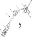
- FIG. 3Ais a top perspective view depicting a closed system catheter assembly including a catheter assembly operably coupled to a catheter insertion device, in accordance with an embodiment of the disclosure.
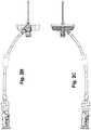
- FIG. 3Bis a top view depicting the closed system catheter assembly of FIG. 3A .
- FIG. 3Cis a bottom view depicting the closed system catheter assembly of FIG. 3A .
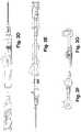
- FIG. 3Dis a right side view depicting the closed system catheter assembly of FIG. 3A .
- FIG. 3Eis a left side view depicting the closed system catheter assembly of FIG. 3A .
- FIG. 3Fis a rear view depicting the closed system catheter assembly of FIG. 3A .
- FIG. 3Gis a front view depicting the closed system catheter assembly of FIG. 3A .
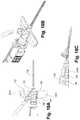
- FIG. 4Ais a perspective view depicting an intravenous catheter assembly having a catheter operably coupled to a catheter insertion device in accordance with an embodiment of the disclosure, wherein the catheter insertion device is in the ready for use position.
- FIG. 4Bis a perspective view depicting the intravenous catheter assembly of FIG. 4A , wherein the intravenous catheter assembly is decoupled from the catheter insertion device, and the catheter insertion device is in the needle retracted, safe position.
- FIG. 5Ais a side perspective view depicting a needle assembly of a catheter insertion device in accordance with an embodiment of the disclosure.
- FIG. 5Bis a distal end view depicting the catheter insertion device of FIG. 5A .
- FIG. 5Cis a bottom perspective view depicting the catheter insertion device of FIG. 5A .
- FIG. 6Ais a bottom perspective view depicting an interaction between a needle assembly and a needle housing of a catheter insertion device, in accordance with an embodiment of the disclosure, wherein the needle assembly is positioned relative to the needle housing in a distal, engaged, ready for use position.
- FIG. 6Bis a bottom perspective view depicting the interaction between a needle assembly and a needle housing of the catheter insertion device of FIG. 6A , wherein the needle assembly is positioned relative to the needle housing in a proximal, disengaged, safe position.
- FIG. 7Ais a perspective view depicting an intravenous catheter assembly having a passive release mechanism in accordance with an embodiment of the disclosure, wherein the intravenous catheter assembly includes a catheter operably coupled to an catheter insertion device via a passive release mechanism, and wherein the catheter insertion device is in the ready for use position.
- FIG. 7Bis a perspective view depicting the intravenous catheter assembly of FIG. 7A , wherein the intravenous catheter assembly is decoupled from the catheter insertion device, and the catheter insertion device is in the needle retracted, safe position.
- FIG. 8Ais an exploded, perspective view depicting a first side of a passive release mechanism in accordance with an embodiment of the disclosure.
- FIG. 8Bis an exploded, perspective view depicting a second side of the passive release mechanism of FIG. 8A .
- FIG. 9Ais a fragmentary, cross-sectional view depicting an intravenous catheter assembly in accordance with an embodiment of the disclosure, wherein the intravenous catheter assembly includes a passive release mechanism having a retainer and collar positioned relative to one another so as to engage a catheter hub in a ready for use position.
- FIG. 9Bis a fragmentary, cross-sectional view depicting the intravenous catheter assembly of FIG. 9A , wherein the retainer and collar are positioned relative to one another so as to disengage from the catheter hub in a safe position.
- FIG. 10Ais a profile view depicting a catheter tube, catheter hub and wing assembly in accordance with an embodiment of the disclosure.
- FIG. 10Bis a cross-sectional view depicting the catheter tube, catheter hub and wing assembly of FIG. 10A .
- FIG. 11depicts an exploded, perspective view depicting the catheter hub body and a septum retainer in accordance with an embodiment of the disclosure.
- FIG. 12a perspective view depicting another embodiment of a septum retainer in accordance with the disclosure.
- FIG. 13is a partial view depicting a catheter assembly in accordance with an embodiment of the disclosure.
- FIG. 14is a partial, semitransparent view depicting an assembled catheter assembly operably coupled to a catheter insertion device in accordance with an embodiment of the disclosure.
- FIG. 15is an end view of a proximal end depicting a septum retainer in accordance with an embodiment of the disclosure.
- FIG. 16is a partial, semitransparent view depicting a septum retainer and septum operably coupled to a catheter insertion device in accordance with an embodiment of the disclosure.
- FIG. 17is a partial, cross-sectional view depicting a septum retainer and a septum operably coupled to a catheter insertion device in accordance with an embodiment of the disclosure.
- FIG. 18Ais a fragmentary, top view depicting an intravenous catheter assembly in accordance with an embodiment of the disclosure.
- FIG. 18Bis a fragmentary, perspective view depicting the intravenous catheter assembly of FIG. 18A .
- FIG. 18Cis a fragmentary, profile view depicting the intravenous catheter assembly of FIG. 18A .
- FIG. 19Ais a partial cross sectional view depicting a catheter hub, septum retainer and a septum in accordance with an embodiment of the disclosure.
- FIG. 19Bis a cross sectional view depicting the catheter hub, septum retainer and septum of FIG. 19A .
- FIG. 20is an end view depicting a septum having a slit with a needle passing therethrough in accordance with an embodiment of the disclosure.
- FIG. 21Ais a partial cross sectional view depicting a catheter hub, septum retainer and a septum in accordance with an embodiment of the disclosure.
- FIG. 21Bis a cross sectional view depicting the catheter hub, septum retainer and septum of FIG. 21A .
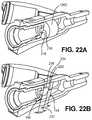
- FIG. 22Ais a partial cross sectional view depicting a catheter hub, septum retainer and a septum in accordance with an embodiment of the disclosure.
- FIG. 22Bis a cross sectional view depicting the catheter hub, septum retainer and septum of FIG. 22A .
- FIG. 23Ais a partial cross sectional view depicting a catheter hub, septum retainer and a septum in accordance with an embodiment of the disclosure.
- FIG. 23Bis a cross sectional view depicting the catheter hub, septum retainer and septum of FIG. 23A .
- FIG. 24Ais a partial cross sectional view depicting a catheter hub, septum retainer and a septum in accordance with an embodiment of the disclosure.
- FIG. 24Bis a cross sectional view depicting the catheter hub, septum retainer and septum of FIG. 24A .
- FIG. 25Ais a partial cross sectional view depicting a catheter hub, septum retainer and a septum in accordance with an embodiment of the disclosure.
- FIG. 25Bis a cross sectional view depicting the catheter hub, septum retainer and septum of FIG. 25A .
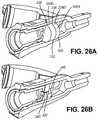
- FIG. 26Ais a partial cross sectional view depicting a catheter hub, septum retainer and a septum in accordance with an embodiment of the disclosure.
- FIG. 26Bis a cross sectional view depicting the catheter hub, septum retainer and septum of FIG. 26A .
- FIG. 27Ais a profile view depicting a needleless connector in accordance with an embodiment of the disclosure.
- FIG. 27Bis a cross sectional view depicting the needleless connector of FIG. 27A in a closed configuration.
- FIG. 27Cis a cross sectional view depicting the needleless connector of FIG. 27A in an open configuration coupled to an IV fluid supply.
- FIG. 28is a perspective view of an intravenous catheter assembly having a “Y” connector connecting to two needleless connectors in accordance with an embodiment of the disclosure.
- FIG. 29Ais a perspective view depicting a vent cap in accordance with an embodiment of the disclosure.
- FIG. 29Bis another perspective view depicting the vent cap of FIG. 29A .
- FIG. 29Cis a sectional view depicting the vent cap of FIG. 29A .
- FIG. 30Ais a cross-sectional view depicting a vent cap and needleless connector in accordance with an embodiment of the disclosure, wherein the vent cap is in a first, storage position relative to the needleless connector.
- FIG. 30Bis a cross-sectional view depicting the vent cap and needleless connector of FIG. 30A , wherein the vent cap is in a second, actively depressed position relative to the needleless connector.
- FIG. 31Adepicts the preparation of a biological site for insertion of a catheter insertion device in accordance with an embodiment of the disclosure.
- FIG. 31Bdepicts the insertion of a needle and catheter tube into the vein of a patient in accordance with an embodiment of the disclosure.
- FIG. 31Cdepicts the retraction of the needle from the catheter tube in accordance with an embodiment of the disclosure.
- FIG. 31Ddepicts the removal of a catheter insertion device from a biological site in accordance with an embodiment of the disclosure.
- FIGS. 1A-Ba conventional IV catheter assembly 20 is depicted. Details of the conventional IV catheter assembly 20 are described in the Background section above.
- a catheter assembly 100is depicted in accordance with an embodiment of the disclosure.
- the catheter assembly 100can be a closed system catheter.
- a closed system catheter assembly 101is depicted in accordance with an embodiment of the disclosure.
- the closed system catheter assembly 101can include a catheter assembly 100 operably coupled to a catheter insertion device 102 .
- Catheter insertion device 102can provide an insertion needle 104 , over which a portion of a catheter tube 108 coaxially rides.
- Various types of catheter insertion devices 102are marketed by Smiths Medical ASD, Inc. of St. Paul, Minn., under the JELCO trademark.
- One embodiment of a catheter insertion device 102(such as that depicted in FIGS. 1A-B ) is described in U.S. Pat. Nos. 7,291,130 and 8,257,322 (depicting an IV catheter insertion device marketed by Smiths Medical ASD, Inc. under the INTUITIV trademark), both of which are incorporated by reference herein.
- the catheter insertion device 102can provide a safety needle assembly (such as that depicted in FIGS. 3A-G and FIGS. 4A-B ), which functions to house the sharpened needle tip 106 of the insertion needle 104 to reduce the likelihood of an inadvertent needle stick.
- FIG. 4Adepicts the catheter insertion device 102 in a first or ready for use position, in which the catheter assembly 100 is selectively coupled to the catheter insertion device 102 .
- the catheter assembly 100which can include a catheter tube 108 and a catheter hub 110 , can be positioned over the insertion needle 104 of the catheter insertion device 102 , with a sharpened needle tip 106 of the insertion needle 104 protruding from a distal end of the catheter tube 108 .
- a protective sheath or needle cover(not depicted) can be operably coupled to either the catheter assembly 100 or the catheter insertion device 102 , and positioned over the sharp needle tip 106 to inhibit unwanted needle sticks.
- the closed system catheter assembly 101which can include the catheter assembly 100 and catheter insertion device 102 , can be provided for use in a sterilized and assembled state, contained within a hermetically sealed package.
- a clinicianTo insert the catheter tube 108 into a vein of a patient or subject, a clinician first removes the closed system catheter assembly 101 from the packaging. The needle sheath is removed to expose the sharp needle tip 106 of the insertion needle 104 protruding from the distal end of the catheter tube 108 . The clinician then punctures an identified site of the subject with the sharpened needle tip 106 and urges the needle 104 forward until the sharpened needle tip 106 enters the vein of the subject. In some embodiments, an initial amount of blood or bodily fluid can pass through a lumen of the needle 104 , and enter the catheter assembly 100 and/or catheter insertion device 102 such that the clinician can view the “flashback” of the blood or bodily fluid to confirm entry into the vein.
- the catheter assembly 100can then be moved distally over the needle 104 , threading the catheter tube 108 into the vein of the subject as the needle 104 is held stationary.
- the cliniciancan withdraw the needle 104 by pulling a needle assembly 103 of the catheter insertion device 102 proximally, away from the subject while holding the catheter assembly 100 generally stationary with respect to the subject.
- the needle assembly 103can be pulled proximally until the needle 104 of the catheter insertion device 102 is separated from the catheter assembly 100 and safely housed within the needle housing 105 of the catheter insertion device 102 , which is referred to as the second or safe position.
- FIG. 4Bdepicts the intravenous catheter assembly 100 and the safe position. In the safe position, the clinician can dispose of the catheter insertion device 102 in a sharps container.
- distalrefers to the direction along an access that lies parallel to the needle 104 of the closed system catheter assembly 101 that is closest to the subject during catheter insertion.
- proximalrefers to the direction lying along the axis parallel to the needle 104 that is further away from the subject when the catheter is inserted into the vein of the subject, opposite to the distal direction.
- the needle assembly 103can include an insertion needle 104 operably coupled to a needle hub 262 .
- Needle 104can include an elongate, cylindrically shaped metal structure defining a lumen that extends between a sharpened distal needle tip 106 and a proximal end 264 .
- the sharp needle tip 106can be constructed and arranged to pierce the skin of a subject during catheter insertion.
- the sharp needle tip 106can include a V-point designed to reduce the penetration force used to penetrate the needle 104 and a portion of the catheter insertion assembly 102 through the skin, tissue, and vein wall of a subject.
- the length of the needle 104can be extended to aid in the insertion of the catheter assembly 100 into obese patients.
- Needle 104can further include a transition 266 that has a different cross-sectional size and/or shape than portions of the needle 104 that lie proximal to the transition 266 .
- Needle transition 266(alternatively referred to as a needle pump or cannula bump) can be created by crimping opposed sides of the needle 104 , or otherwise disrupting the structure of the needle 104 , so that the outer surfaces of the needle 104 extend to a larger radial position than other portions of the needle 104 , as measured from the center of the needle axis.
- Transitionals 266can be formed differently, according to alternate embodiments, such as by adding material to the exterior of the needle, among other ways.
- Proximal end 264 of the needle 104can be operably coupled to the needle hub 262 .
- Needle hub 262can be connected to a needle grip 268 positioned on the exterior of the needle housing 105 when assembled thereto for access by a clinician.
- the needle hub 262 and the needle grip 268can be operably coupled to one another by a protuberance 270 that can be formed from the same unitary structure as the needle grip 268 and the needle hub 262 .
- the needle assembly 103can be constructed to provide a visual indication of flashback when the sharpened needle tip 106 of the needle 104 enters the vein of a subject.
- the needle hub 262includes a flash chamber 272 in fluid communication with the lumen of the needle 104 .
- the flash chamber 272can be sealed at one end by a flash plug 274 .
- Flash plug 274can be made out of an air permeable, hydrophilic material that enables the passage of air, but inhibits the passage of liquid.
- Needle hub 262can be constructed of a clear or translucent material to enable a clinician to view the presence of blood within the flash chamber 272 .
- the cliniciancan be alerted when the needle has entered the vein of the subject by the presence of blood in the flash chamber 272 .
- features of the needle assembly 103can provide an indication that the sharp needle tip 106 has entered the vein of a subject.
- the needle 104can include a notch 276 .
- blood flowenters the needle lumen when the sharpened needle tip 106 enters the vein.
- some bloodpasses through the notch 276 and into the annular space that lies between the exterior of the needle 104 and the interior of the catheter tube 108 .
- the presence of blood in the annular spacecan be viewed by a clinician through clear or translucent portions of the catheter tube 108 , providing an indication that the sharpened needle tip 106 is present in a vein.
- the needle housing 105can have a generally cylindrical, elongate body 278 that extends from a proximal end 280 to a distal end 282 .
- a longitudinal slot 284can be formed along and underside of the needle housing 105 and extend from a proximal slot end 286 near the proximal end 280 of the needle housing 105 to a distal slot end 288 near the distal end 282 of the needle housing 105 .
- Needle assembly 103can be slidably coupled to the needle housing 105 .
- the needle assembly 103can have a “C” shaped cross section conformed to fit around the outer surface of the needle housing 105 in a manner that inhibits the needle assembly 103 from readily separating from the needle housing 105 , yet enabling the needle assembly 103 to slide along the longitudinal axis of the needle housing 105 with minimal resistance.
- the longitudinal slot 284can slidably receive the protuberance 270 of the needle assembly 103 , with the needle grip 268 positioned outside of the needle housing 105 and at least a portion of the needle hub 262 and the needle 104 positioned internally to the needle housing 105 , thereby at least partially housing these features.
- the needle assembly 103can be configured to slide along the longitudinal slot 284 to restrict the needle assembly 103 from rotating about the longitudinal axis of the needle housing 105 .
- the protuberance 270 slidably received within the longitudinal slot 284enables linear movement of the needle hub 262 substantially parallel to the longitudinal axis of the needle housing 105 , but restricts the rotational movement of the needle assembly 103 relative to the needle housing 105 .
- Longitudinal slot 284can guide the needle assembly 103 in motion with respect to the needle housing 105 between the ready for use position (as depicted in FIG. 6A ) and the safe position (as depicted in FIG. 6B ).
- the ready for use positiona portion of the needle 104 extends from the needle housing 105 , such that the sharp needle tip 106 of the needle 104 protrudes beyond the needle housing 105 .
- the needle 104is withdrawn, and the sharp needle tip 106 is housed within the needle housing 105 in a manner intended to reduce or eliminate the likelihood of an inadvertent needle stick.
- Catheter insertion device 102can include a needle lock 290 that engages a needle assembly at a position that is proximal to the sharp needle tip 106 to inhibit the sharp needle tip 106 from being accessed after the needle 104 is used to insert the catheter assembly 100 . In this manner, access to the sharp needle tip 106 is inhibited when the needle 104 is in the safe position. Needle lock 290 can thus be configured to interlock the needle assembly 103 to the needle housing 105 in the safe position. In one embodiment, the needle lock 290 can be positioned on a proximal portion of the needle housing 105 at the proximal slot end 286 to engage the protuberance 270 . Several different types of locking mechanisms can be used for this purpose.
- the longitudinal slot 284 of the needle housing 105can have a bottleneck 292 defined in it, where the bottleneck 292 of the longitudinal slot 284 generally has a narrower width than the rest of the longitudinal slot 284 .
- Protuberance 270 of the needle assembly 103can be triangular or wedge like in shape where the apex of the wedge faces the bottleneck 292 when in the ready for use position. When an external force is applied to the needle assembly 103 in an effort to slide it to the safe position, the apex of the wedge of the protuberance 270 can come into contact with the bottleneck 292 .
- Bottleneck 292which can have a width narrower than that of the protuberance 270 , can initially resist movement of the protuberance 270 through the bottleneck 292 . However, with sufficient force, the wedge shape protuberance 270 can cause the bottleneck 292 to temporarily deform, thereby enabling the protuberance 270 to pass through the bottleneck 292 .
- the interaction between the wedge shape protuberance 270 and the bottleneck 292can create an audible “click” noise, tactile, or visual indication that the protuberance 270 has passed through the bottleneck 292 . Thereafter, the protuberance 270 will be unable to pass back through the bottleneck 292 in the opposite direction, and the needle 104 will be locked in the safe position relative to the needle housing 105 .
- the catheter insertion device 102can include an end cap 263 (as depicted in FIGS. 3A-G ).
- the end cap 263can be coupled to the needle grip 268 and/or needle hub 262 , thereby covering the proximal end 280 of the needle housing 105 .
- End cap 263can have a proximal end 265 that can provide a surface against which a clinician can press during the catheter insertion procedure, as discussed herein.
- the intravenous catheter assembly 100can include a passive release mechanism 298 .
- Passive release mechanism 298can be configured to couple the catheter hub 110 to the catheter insertion device 102 in the ready for use position (as depicted in FIG. 7A ) and release the catheter hub 110 from the catheter insertion device 102 and the safe position (as depicted in FIG. 7B ).
- the passive release mechanism 298can include one or more catheter hub contacts that inhibit release of the catheter assembly 100 from the catheter insertion device 102 until after the sharp needle tip 106 of the catheter insertion device 102 is in the safe position, where access to the sharp needle tip 106 is inhibited.
- the cathetercan be “passively” released by a clinician to obtain “passive” safety.
- the catheter assembly 100can be released when a clinician pulls on a portion of the catheter insertion device 102 as the clinician withdraws the needle 104 from the catheter assembly 100 .
- Passive release mechanism 298can include a retainer 302 and a collar 304 .
- Retainer 302can be received within the collar 304 , and can include an actuator 306 and a nose 308 , such that the actuator 306 and the nose 308 can form a unitary structure.
- Retainer 302can be slidably engaged with the collar 304 .
- Retainer 302can include one or more external hub contacts 310 and one or more interior hub contacts 312 , wherein both the external hub contacts 310 and internal hub contacts are configured to contact the catheter hub 110 , thereby securely engaging the catheter hub 110 to the passive release mechanism 298 when the actuator 306 is in the distal, engaged position.
- collar 304can include one or more exterior hub contacts 313 .
- the retainer 302 and the collar 304can be shaped and sized such that the catheter hub 110 is receivable at least partially within the collar 304 and at least partially over the nose 308 .
- Actuator 306can be shiftable between a distal, engaged, ready for use position (as depicted in FIG. 9A ), wherein the collar 304 can receive a proximal end of the catheter hub 110 and the nose 308 can engage with an interior of the catheter hub 110 , and a proximal, disengaged, safe position (as depicted in FIG. 9B ), wherein the catheter hub 110 is released from the retainer 302 and the collar 304 .
- a length of the nose 308 that extends within the interior of the catheter hub 110can be at least twice the diameter of the nose 308 .
- the interior of the catheter hub 110can be resilient to facilitate disengagement of the catheter hub 110 from the nose 308 .
- Nose 308can include a needle passage 314 that can include a wider portion 316 and a narrower portion 318 .
- the wider portion 316can be distal to the narrower portion 318 .
- the wider portion 316can be sized so that the needle 104 , including the needle transition 266 can be received therein.
- the narrower portion 318can be sized to closely approximate the diameter of the needle 104 without the needle transition 266 . Accordingly, the needle transition 266 will contact a needle abutment 320 at the juncture of the wider portion 316 and the narrower portion 318 to inhibit further passage of the needle 104 .
- Nose 308can be structured to sheath the sharpened needle tip 106 when the sharp needle tip 106 is retracted to the disengaged, safe position.
- Shifting of the retainer 302can occur just prior to the needle assembly 103 reaching the safe position, such that in the proximal, disengaged safe position the exterior hub contacts 310 , 313 and/or the interior hub contacts 312 can be disengaged from the catheter hub 110 , thereby enabling the catheter hub 110 to be released from the passive release mechanism 298 .
- a longitudinal axis of the needle assembly 103 and a longitudinal axis of the catheter hub 110can be substantially coaxial or parallel.
- the catheter hub 110can be disengaged from the retainer 302 and the collar 304 by angular rotation of the catheter hub 110 relative to the needle assembly 103 , such that the longitudinal axis of the catheter hub 110 is not aligned with the longitudinal axis of the needle assembly 103 .
- passive release mechanismis understood to refer to features of a catheter insertion device 102 that inhibit the release of a catheter assembly 100 until after the catheter insertion device 102 is in the safe position. Some or all of the features of the passive release mechanism 298 can be integral with other components of the catheter insertion device 102 . In this respect, the term “passive release mechanism” does not necessarily refer to a component that is separate from the needle assembly 103 and/or needle housing 105 . Rather, it is to be appreciated that the passive release mechanism 298 , the needle assembly 103 , and/or needle housing 105 can comprise the passive release mechanism 298 .
- Catheter assembly 100generally includes a catheter tube 108 and a catheter hub 110 .
- the catheter assembly 100can optionally include a wing assembly 112 , an extension tube 114 , an extension tube clamp 116 , a needleless connector 118 , and a vent cap 120 .
- catheter assembly 100can be a closed system catheter configured to inhibit blood from escaping after withdrawal of the needle 104 , thereby reducing the risk of exposure of blood or other bodily fluids to clinicians, particularly a consideration of sensitivity where blood-borne diseases may be present.
- embodiments of catheter assembly 100can inhibit the introduction of unwanted contaminants into the interior of catheter assembly 100 prior to the connection to an IV fluid supply.
- catheter tube 108can extend from a distal end 124 to a proximal end 126 , where the catheter tube 108 can be operably coupled to the catheter hub 110 .
- the catheter tube 108can define a lumen 128 configured to provide a fluid pathway between the vein of a subject and the catheter hub 110 .
- the catheter tube 108can include a barium radio opaque line 129 to ease in the identification of the catheter tube 108 during radiology procedures.
- Catheter hub 110can include a catheter hub body 130 , a septum 132 and a septum retainer 134 .
- Catheter hub body 130can have a distal end 136 , a proximal end 138 and an internal wall 140 defining a first internal fluid passageway 142 therebetween.
- the distal end 136 of the catheter hub body 130is operably coupled to the proximal end 126 of the catheter tube 108 , such that the lumen 128 of the catheter tube 108 is in fluid communication with the first internal fluid passageway 142 .
- the internal wall 140further defines a transitional step 144 within the first internal fluid passageway 142 between a smaller diameter portion 146 of the first internal fluid passageway 142 proximal to the distal end 136 , and a larger diameter portion 148 of the first internal fluid passageway 142 distal to the proximal end 138 .
- the internal wall 140further defines a side port 150 .
- the side port 150is in fluid communication with the first internal fluid passageway 142 .
- the side port 150extends away from the first internal fluid passageway 142 and at an oblique angle to the lumen 128 of the catheter tube 108 .
- Side port 150can provide a connection point to one or more lengths of extension tube 114 , so that the inside of the extension tube 114 is in fluid communication with the first internal fluid passageway 142 .
- the internal wallcan further include an extension tube connection point 152 .
- Septum 132can have a distal end 154 , a proximal end 156 and an outer perimeter 158 .
- Septum 132can be self-sealing, so that when the needle 104 is withdrawn through the septum 132 , any void left by the withdrawn needle 104 will close to provide a seal, and the septum 132 will maintain its fluid impermeability.
- the septum 132is positioned partially within the first internal fluid passageway 142 , such that the distal end 154 of the septum 132 abuts up against the transitional step 144 , thereby inhibiting forward movement of the septum 132 within the first internal fluid passageway 142 .
- Septum 132can be constrained about its outer perimeter 158 by the internal wall 140 of the catheter hub body 130 . Rearward movement of the septum 132 can be restricted or inhibited by the septum retainer 134 .
- the shape of the first internal fluid passageway 142is configured to promote a more even flow of fluid throughout the first internal fluid passageway 142 to improve flushability of the catheter assembly 100 .
- the first internal fluid passagewayis shaped to reduce the occurrence of dead spaces or pockets, thereby reducing the areas where microbial growth is more likely to occur.
- the angles of the internal wall 140 of the first internal fluid passageway 142can be chamfered or filleted to reduce the dead spaces or pockets that may otherwise exist in the interior corners of the internal fluid passageway 142 .
- the septum 132can be positioned in close proximity to the side port 150 to reduce the dead spaces or pockets and proximal portions of the first internal fluid passageway 142 .
- Septum retainer 134can be configured to secure the septum 132 in position within the first internal fluid passageway 140 .
- the septum retainer 134can have a distal end 160 , a proximal end 162 , an inner wall 164 , and an outer wall 166 therebetween.
- Septum retainer 134can be at least partially or fully receivable within the first internal fluid passageway 140 of the catheter hub body 130 .
- the proximal end 162 of the septum retainer 134is flush with, or recessed with respect to the proximal end 138 of the catheter hub body 130 (as depicted in FIGS. 10B and 12 ).
- the inner wall 164defines a second internal passageway 168 that can be used to accommodate an insertion needle 104 of the catheter insertion device 102 .
- the outer wall 166defines an aperture 170 configured to enable the needle 104 to pass therethrough.
- FIG. 11an exploded, perspective view of the catheter hub body 130 and a septum retainer 134 is depicted in accordance with an embodiment of the disclosure.
- FIG. 12a perspective view of another embodiment of a septum retainer 134 is depicted in accordance with the disclosure.
- the outer wall 166is shaped and sized to interlock with the internal wall 140 of the catheter hub body 130 , thereby coupling the septum retainer 134 to the catheter hub body 130 .
- FIG. 13a partial view of an assembled catheter assembly 100 is depicted in accordance with an embodiment of the disclosure.
- FIG. 14a partial, semitransparent view of an assembled catheter assembly 100 operably coupled to a catheter insertion device 102 is depicted in accordance with an embodiment of the disclosure.
- the septum retainer 134is snap fit into the catheter hub body 130 , without the use of adhesives or ultrasonic welding to couple the septum retainer 134 to the catheter hub body 130 .
- a circumferential retainer ridge 172can be formed into a portion of the outer wall 166 , such that the outer wall 166 and the circumferential retainer ridge 172 are shaped and sized to interlock with the internal wall 140 of the catheter hub body 130 .
- the internal wall 140 of the catheter hub body 130can include a circumferential channel 174 , configured to receive the circumferential retainer ridge 172 (depicted in FIGS. 10B and 14 ).
- the septum retainer 134can include a plurality of lateral ribs 176 positioned on the outer wall 166 .
- Lateral ribs 176can be configured to provide friction between the septum retainer 134 and the catheter hub body 130 , so as to inhibit the septum retainer 134 from rotating relative to the catheter hub body 130 when the septum retainer 134 is assembled with the catheter hub body 130 .
- the internal wall 140 of the catheter hub body 130can be configured to at least partially receive a portion of the plurality of lateral ribs 176 .
- the septum retainer 134can include one or more lateral nubs 177 positioned on the interior wall 164 .
- the septum retainer 134can include one or more lateral nubs 177 positioned on the interior wall 164 .
- three lateral nubs 177can be positioned on the interior wall 164 and can be configured to protrude inwardly from the interior wall 164 toward the second internal fluid passageway 168 .
- FIG. 16a partial, semitransparent view of a septum retainer 134 and septum 132 operably coupled to a catheter insertion device 102 is depicted in accordance with an embodiment of the disclosure.
- FIG. 17a partial, cross-sectional view of a septum retainer 134 and a septum 132 operably coupled to a catheter insertion device 102 is depicted in accordance with an embodiment of the disclosure.
- lateral nubs 177can be configured to provide friction between the septum retainer 134 and the nose 308 of the passive release mechanism 298 , so as to inhibit the septum retainer 134 , and the catheter hub 110 generally, from rotating relative to the catheter insertion device 102 when the catheter assembly 100 is coupled to the catheter insertion device 102 .
- the friction provided by the lateral ribs 176is greater than the friction provided by the lateral nubs 177 , such that when a rotational force is applied, the septum retainer 134 will rotate relative to the catheter insertion device 102 before the septum retainer 134 will rotate relative to the catheter hub body 130 .
- the proximal end 138 of the catheter hub body 130can include a lug 139 .
- Lug 139can be configured to orient the catheter hub 110 relative to the catheter insertion device 102 , such that the catheter hub 110 can be captured by the passive release mechanism 298 .
- lug 139can be configured as a portion of the Luer lock connection.
- the catheter hub body 130can include one or more ledges 178 configured to provide structural reinforcement as support for a wing assembly 112 .
- the ledges 178can define one or more holes 180 .
- the holes 180can provide improved contact with the wing assembly 112 , when the wing assembly 112 is integrally molded onto a portion of the catheter hub body 130 .
- the ledges 178can serve to both increase the bonding surface between the catheter hub 110 and the wing assembly 112 , as well as to serve as a partial structural reinforcement for the wing assembly 112 , while at the same time enabling the wing assembly 112 to maintain its flexibility.
- FIGS. 18A-Cdepict partial views of the intravenous catheter assembly 100 having a wing assembly 112 in accordance with an embodiment of the disclosure.
- the wing assembly 112can include one or more flexible wings 181 A/B, a heel portion 182 and a collar 183 .
- the one or more wings 181 A/Bcan generally extend outwardly from a central axis of the catheter tube 108 /catheter hub 110 , so as to provide an adequate gripping surface for a clinician, as well as an extended surface for aid in securing the catheter hub 110 in place on the patient.
- the one or more wings 181 A/Bcan have a front edge or distal portion 185 and a rear edge or proximal portion 187 .
- the distal portion 185 of the wings 181can form a substantially straight line, extending substantially orthogonal to the axis of the catheter tube 108 /catheter hub 110 for improved contact with the skin of the patient.
- the distal portion 185 of the wings 181can be concave, so as to form a slight arc, such that the distal edge of the wings 181 extends distally farther than the distal portion of the pair of wings proximal to the catheter tube 108 .
- a top surface of the wings 181can define a concave surface configured to aid a clinician in gripping the catheter hub 110
- the heel portion 182can extend from the proximal portion 187 of the wings 181 towards the proximal end 138 of the catheter hub 110 .
- the heel portion 182can be a wedge shaped structure configured to support a proximal portion of the catheter hub 110 proximal to the one or more wings 181 .
- the collar 183can at least partially wrap around a central axis of the catheter hub 110 .
- the wing assembly 112can be integrally molded onto the catheter hub 110 , such that the collar at least partially wraps around a proximal portion of the catheter hub 110 .
- wing assembly 112can be integrally molded over the one or more ledges 178 , with one or more holes 180 defined therein, such that the one or more ledges 187 provide structural reinforcement and support for the wing assembly 112 .
- the bottom surface of the wings 181 and a bottom surface of the heel portion 182can form a contiguous surface 184 .
- the contiguous surface 184can be angled relative to the catheter tube 108 , such that the catheter tube 108 can remain in a substantially straight line configuration, without a significant bend or hinge point when the catheter tube 108 is inserted into a patient and the wings 181 are secured to the patient's skin. Sloped contiguous surface 184 enables the wings 181 to be substantially parallel to the skin of the patient, thereby increasing the surface contact between the one or more wings 181 and the patient's skin.
- the contiguous surface 184is angularly offset from the axis of the catheter tube 108 by an angle that ranges between seven and nine degrees. In one embodiment, the contiguous surface 184 is offset from the axis of the catheter tube 108 by approximately eight degrees.
- the wing assembly 112can have a lower modulus of elasticity the catheter hub 110 , thereby enabling the wing assembly 112 to more easily twist and bend to conform to the contours of the skin of the patient.
- the contiguous surface 184can include a textured pattern, such as a tread, to increase the frictional resistance with the skin of the patient (as best depicted in FIG. 2C ).
- the contiguous surface 184can include a plurality of grooves positioned substantially orthogonal to the longitudinal axis of the catheter tube 108 to inhibit the catheter hub 110 from sliding proximally during use.
- the contiguous surface 184can include a plurality of grooves positioned substantially parallel to the longitudinal axis of the catheter tube 108 to inhibit the catheter hub 110 from sliding side to side during use.
- the substantially orthogonal groovescan be positioned on the one or more wings 181 and the substantially parallel grooves can be positioned on the heel portion 182 .
- the textured patterncan aid in preventing perspiration build up, which can occur with a flat or smooth surface. In one embodiment, the textured pattern inhibits the creation of high-pressure areas that may cause discomfort.
- the septum 132can be configured to inhibit fluid passage during catheter assembly 100 insertion and/or when the needle 104 extends through the septum 132 .
- a resilient design of the septum 132can inhibit the septum 132 from retaining a “set” or memory of the opening caused by the needle 104 passing therethrough over the course of the often three or more years that the intravenous catheter assembly 100 may remain in storage prior to use.
- the septum 132can be configured to provide a fluid tight seal under pressure injection, in which the injected medicament can be pressurized to 300 psi or greater, up to 325 psi or greater, or up 350 psi or greater, according to various example embodiments. Septum 132 can also maintain a fluid tight seal under increased flow rates, in which the injected medicament can be administered at up to a rate of 3 mL per second or up to 5 mL per second, according to various example embodiments.
- septum 132can be configured to provide good sealing properties to inhibit fluid from passing from the first internal fluid passageway 142 to the second internal fluid passageway 168 , it can also enable the needle 104 to be retracted without undue resistance, or “drag” force between the interaction of the needle 104 and the septum 132 as the needle 104 is retracted. Accordingly, septum 132 can create a balance between good sealing properties and the reduction of frictional drag on the needle 104 as it is retracted into the safe position.
- the septum 132is sized to fit within the first internal fluid passageway 142 to create a fluid tight seal with the internal wall 140 to inhibit fluid within the lumen 128 or the first internal fluid passageway 142 from escaping through the proximal end 138 of the catheter hub body 130 .
- the septum 132is constructed of a flexible, fluid impermeable material.
- the septum 132can be constructed of silicone, isoprene, or other flexible materials.
- the septum 132may be radially compressed within the catheter hub body 130 to promote a seal with the catheter hub body 130 and/or the insertion needle 104 when present in the septum 132 .
- the septumis compressed up to 10% by volume, up to 15% by volume, up to 20% by volume, or even greater.
- septum 126 Bcan have an internal surface 216 defining a slit 218 passing from the distal end 154 to the proximal end 156 .
- the slit 218can be configured to enable an insertion needle to pass therethrough.
- FIG. 20an end view of a septum 126 B having a needle 104 passing through slit 218 is depicted in accordance with an embodiment of the disclosure.
- needle 104slides relative to the septum 126 B through slit 218 .
- the configuration of the slit 218generally provides a reduced amount of frictional resistance or drag force in comparison to conventional septum designs.
- the reduction in drag forceis due in part to the “cat's-eye” shape formed by the slit 218 when the needle passes therethrough.
- the width and/or configuration of the slit 218can affect the degree to which the cat's-eye shape is formed.
- septum 126 Ccan have an internal surface 216 defining an aperture 220 passing from the distal end 154 to the proximal end 156 .
- the aperture 220can be configured to enable an insertion needle 104 to pass therethrough.
- the configuration of the aperture 220generally provides good sealing properties in comparison to conventional septum designs.
- septum 126 Dcan have an internal surface 216 defining an aperture 220 originating at the distal end 154 and passing through a first thickness 222 , and a slit 218 originating at the termination of the aperture 224 and passing through the proximal end 156 , thereby passing through a second thickness 226 .
- the aperture 220 and slit 218are together configured to enable the needle 104 to pass therethrough.
- a portion of slit 218 proximal to aperture 220can be tapered towards aperture 220 . Accordingly, this embodiment complements the reduced drag force of the slit 218 with the good sealing properties of the aperture 220 .
- septum 126 E-Hcan include a first septum portion 228 A-D having a distal end 230 and a proximal end 232 , and a second septum portion 234 A-D having a distal end 236 and a proximal end 238 , wherein the proximal end 232 of the first septum portion 228 A-D is operably coupled to the distal end 236 of the second septum portion 234 A-D.
- first septum portion 228 A-Bcan have an internal surface 240 defining an aperture 220 passing from the distal end 230 to the proximal end 232 .
- Second septum portion 234 A-Bcan have an internal surface 242 defining a slit 218 passing from the distal end 236 to the proximal end 238 .
- the slit 218can pass entirely through second septum portion 234 A-B to the outer perimeter 158 .
- the aperture 220 and slit 218 togetherare configured to enable an insertion needle to pass therethrough.
- the slit 218can be smaller, such that it does not extend to the outer perimeter 158 .
- the length of the slitcan be 0.040 inches, 0.060 inches, or 0.080 inches.
- the thickness 244 of the first septum portion 228 Ccan be greater than the thickness 246 of the second septum portion 234 C. In other embodiments, the thickness 244 of the first septum portion 228 C can be less than, or substantially equal to the thickness 246 of the second septum portion 234 C.
- the first septum portion 228 Ccan have an internal surface 240 defining an aperture 220 passing from the distal end 230 to the proximal end 232 .
- Second septum portion 234 Ccan have an internal surface 240 defining a plurality of slits 248 passing from the distal end 236 to the proximal end 238 .
- the plurality of slits 248can be in a tri-slit configuration.
- the aperture 220 and plurality of slits 248 togetherare configured to enable an insertion needle to pass therethrough.
- the first septum portion 228 and/or the second septum portion 234can have a larger diameter than the inside of the catheter hub body 130 , such that the septum portion 228 , 234 can be circumferentially compressed within the catheter hub body 130 .
- first septum portion 228 Dcan have an internal surface 240 defining a large diameter aperture 250 passing from the distal end 230 to the proximal end 232 .
- Second septum portion 234 Dcan have an internal surface 242 defining an aperture 220 passing from the distal end 236 to the proximal end 238 .
- the aperture 220 and aperture 250 togetherare configured to enable an insertion needle to pass therethrough.
- the aperture 250can be slightly smaller than the diameter of the needle 104 that passes therethrough.
- an extension tube 114 and an optional extension tube clamp 116are depicted in accordance with an embodiment of the disclosure.
- the extension tube 114can be substantially transparent or translucent to enable the observation of fluid within the extension tube 114 .
- the optional extension tube clamp 116can be constructed of a resilient material that can be deformed to selectively occlude the extension tube 114 to restrict the passage of fluid.
- a needleless connector 118is depicted in accordance with an embodiment of the disclosure.
- the needleless connector 118is configured to connect the extension tube 114 to a connector of an IV fluid supply line, as partially shown in FIG. 27C .
- the needleless connector 118can be biased to a closed or sealed position (as depicted in FIG. 27B ).
- Connection of the needleless connector 118 to an IV fluid supply 186can cause the needleless connector 118 to shift to the open position (as depicted in FIG. 27C ).
- the needleless connector 118Upon disconnection of the needleless connector 118 from the IV fluid supply 186 , the needleless connector 118 can be biased back to the closed or sealed position.
- the needleless connector 118includes a Luer lock connector 119 for connection to an IV fluid supply 186 .
- needleless connector 118can be a connector described in U.S. Pat. No. 7,713,248 (depicting a needle-free connector marketed by ICU Medical, Inc. under the CLAVE trademark), which is hereby incorporated by reference.
- the needleless connector 118is comprised of a conical internal conduit 188 with one or more fluid path windows 190 , a flexible compression seal 192 capable of selectively covering the internal conduit 188 , and a housing 194 substantially surrounding the internal conduit 188 and the compression seal 192 .
- the exterior of housing 194can have a substantially smooth surface, in which crevices are minimized to promote ease in having a surface that is readily swabbed or cleaned to prevent the growth and/or presence of microbes.
- the interior of housing 194can be configured to promote a more even flow of fluid to improve flushability of the needleless connector 118 .
- the interior of housing 194can be shaped to reduce the occurrence of dead spaces or pockets, thereby reducing the areas where microbial growth is likely to occur.
- Needleless connector 118can prevent the escape of bodily fluid and/or guard against contamination of the fluid path.
- the compression seal 192extends over the fluid path windows 190 of internal conduit 188 , thereby creating a fluid seal to prevent fluid from escaping from the extension tube 114 .
- FIG. 27Cwhen an IV fluid supply connector 186 is inserted into the housing 194 , the compression seal 192 is shifted to an open position, thereby exposing the fluid path windows 190 to the fluid path of the IV fluid supply connector 186 .
- the needleless connector 118selectively enables the flow of fluid through the extension tube 114 , while both sealing the intravenous catheter assembly 100 from the ambient environment and inhibiting the escape of bodily fluid from a patient when the IV fluid supply connector 186 is not attached.
- Needleless connector 118thus enables the intravenous catheter assembly 100 to act as a closed system when not connected to either the catheter insertion device 102 or an IV fluid supply connector 186 . That is the needleless connector 118 , in combination with various embodiments of the vent cap described herein, prevent blood from escaping from the intravenous catheter assembly 100 until an IV fluid supply 186 (or other similar type device) is connected. Additionally, the interior portions of the needleless connector 118 and the extension tube 114 are protected from exposure to the ambient environment. By contrast, many conventional designs (such as that depicted in FIGS. 1A-B ) employ only a Luer lock connector 68 .
- a clamp 66 designed to crimp the extension tube 64is engaged to prevent blood from flowing freely from the patient when the needle assembly 50 is removed. Moreover, the interior of the extension tube 64 between the clamp 66 and the Luer lock connector 68 is exposed to the ambient environment prior to connection to an IV fluid supply.
- an intravenous catheter assembly 100 having a first needleless connector 118 A and a second needleless connector 118 Bis depicted in accordance with an embodiment of the disclosure.
- the intravenous catheter assembly 100can include more than two needleless connectors.
- Needleless connectors 118 A/Bcan be operably coupled to extension tube 114 by a “Y” coupling 115 .
- coupling 115is fixedly coupled to the extension tube 114 at one end, and includes one or more portions of a Luer lock connection at the other ends for respective coupling to needleless connectors 118 A/B.
- vent cap 120various views of a vent cap 120 are depicted in accordance with an embodiment of the disclosure.
- One function of the vent cap 120is to shift the needleless connector 118 from the closed or sealed position to the open position when an IV fluid supply 186 is not attached to the needleless connector 118 for the purpose of venting gas trapped within the intravenous catheter assembly 100 while preventing the escape of blood.
- bodily fluid from a patient in which the catheter tube 108 has been insertedcan provide the necessary pressure to push the trapped gas through the vent cap 120 .
- the vent cap 120can be disposable after use.
- the compression seal 192can be shipped with a vent cap 120 assembled thereto in an activated or open position. However, it has been found that extended compression of the compression seal 192 of some needleless connector 118 embodiments can cause the compression seal 192 to permanently deform.
- some example embodimentsare configured with a vent cap 120 that can be coupled to the needleless connector 118 in a first, initial position, where the vent cap 120 is retained by the needleless connector 118 with the needleless connector 118 in a closed or sealed position.
- the vent cap 120can be moved or shifted to a second position to compress the compression seal 192 , thereby shifting the needleless connector 118 to the open position and enabling the purging of the air trapped therein.
- the vent cap 120can include a nose 196 , a flash plug 198 , a push plate 202 , and one or more needleless connector engagement arms 204 .
- Nose 196can be sized and shaped to fit within the housing 194 of the needleless connector 118 in place of the IV fluid supply connector 186 .
- the nose 196can be tapered.
- Nose 196can include a vent path wall 206 defining a vent path 208 .
- the vent path 208can have a diameter sufficient to receive the portion of internal conduit 188 that would otherwise extend into the IV supply connector, such that the fluid path windows 190 of the needleless connector 118 at least partially reside within the vent path 208 .
- a distal end 210 of the nose 196can be in abutting contact with the compression seal 192 and can provide a fluidic seal therebetween.
- the vent cap 120can be assembled to a needleless connector and movable or shiftable between a first, storage position (as depicted in FIG. 30A ), in which the compression seal 192 of the needleless connector 118 is in an uncompressed state, thereby inhibiting fluid from passing through the vent path 208 , and a second, actively depressed position (as depicted in FIG. 30B ), in which the compression seal 192 of the needleless connector 118 is in a compressed state, thereby permitting fluid to pass through vent path 208 .
- Air permeable barrier 198can be positioned within a portion of the vent path 208 .
- Air permeable barrier 198can be comprised of an air permeable matrix that enables air or gas to vent as blood or bodily fluid fills the vent path 208 , but inhibits the blood or bodily fluid from passing entirely through the vent path 208 .
- the vent cap 120can be constructed of a transparent or translucent material. During the venting of air, blood or other bodily fluid can fill a portion of the vent path 208 , thereby providing a visual confirmation to the clinician that the catheter tube 108 has been inserted into a patient's vein.
- Such visual confirmationcan be referred to as secondary or tertiary flashback, wherein a primary and/or secondary flashback occurs in one or more flashback indicators associated with the catheter insertion device 102 .
- a primary and/or secondary flashbackoccurs in one or more flashback indicators associated with the catheter insertion device 102 .
- flashback indicatorsassociated with the catheter insertion device 102 .
- a clinicianmay initially see flashback as blood flow passes through the notch 276 and into the annular space that lies between the exterior of the needle 104 and the interior of the catheter tube 108 .
- a secondary flashback indicationmay be present when blood from the patient flows proximally through the lumen of the needle 104 and into the flashback chamber 272 .
- a tertiary flashback indicationmay be present when blood flows through the catheter tube 108 , extension tube 114 , needleless connector 118 , and into vent path 208 .
- the time differential between the initial, secondary and tertiary flashbacksmay enable a clinician to confirm that the needle has not extended beyond the subject's vasculature, as may be associated with infiltration/extravasation.
- Nose 196can terminate in a push plate 202 .
- Push plate 202can include a flange 212 configured to provide a surface area for a clinician to push on as the vent cap 120 is manually shifted between the first, storage position and the second, actively depressed position.
- a portion of the vent path wall 206can further define an eyelet 214 .
- Eyelet 214can be configured to provide a fluid path for venting air between the vent path 208 and an exterior of the vent path wall 206 .
- eyelet 214can provide a path for escaping air in the event that the clinician seals the end of the vent path 208 with their finger as the vent cap 120 is shifted to the second, actively depressed position.
- portions of the vent cap 120can include a mechanism configured to provide an audible click and/or tactile feedback when the vent cap 120 has been shifted to the second, actively depressed position.
- the one or more needleless connector engagement arms 204can be configured to grip a portion of the needleless connector 118 .
- one or more needleless connector engagement arms 204can include a ridge 203 to improve a grip of the one or more needleless connector engagement arms to the needleless connector 118 .
- the needleless connector engagement arms 204can be constructed of a resilient material, such that the needleless connector engagement arms 204 tend to regain their original shape after temporary deformation.
- the resiliency of the needleless connector arms 204enables the vent cap 122 to be biased to the first, storage position when coupled to the needleless connector 118 .
- the outer surface of the housing 194 of the needleless connector 118can be tapered to increase in diameter, such that when the vent cap 120 is shifted to the second, actively depressed position, the needleless connector engagement arms 204 are deflected away from one another.
- the resiliency of the needleless connector engagement arms 204can bias the vent cap 120 back to the first, storage position. Accordingly, biasing the vent cap 122 to the first, storage position reduces the likelihood that the compression seal 192 of the needleless connector 118 will permanently deform, as can occur when the compression seal 192 is compressed for long periods of time, according to some embodiments.
- placement of intravenous catheter assembly 100generally includes preparation of the biological site of the patient. Often a tourniquet is applied proximal to the biological site and a variety of techniques can be used to dilate the patient's vein. While wearing disposable gloves, the clinician cleanses the biological site and a vein is retracted or anchored by placing a thumb over the vein about fifty to seventy-five mm distal to the site.
- the needle 104 and catheter tube 108are introduced into the vein by inserting the bevel of the sharp needle tip 106 into the vein at about a twenty to thirty degree angle with the bevel facing up in order to pierce one wall of the vein.
- the cliniciangrips the catheter insertion device 102 for optimum control. If successful, blood from the vein flows through the lumen of the needle 104 , thereby providing a positive indication of vein entry through one or more flashback mechanisms.
- the intravenous catheter assembly 100is lowered towards the skin to decrease the entry angle, and the catheter tube 108 is advanced slightly into the vein.
- the needle 104is loosened and the catheter tube 108 is gently advanced farther up into the vein until the catheter hub 110 is against the biological site.
- the tourniquetis loosened and the needle 104 is withdrawn from the catheter tube 108 .
- the sharp needle tip 106is withdrawn through catheter tube lumen 128 and the septum 132 .
- the self-sealing nature of the septum 132closes any void left by the needle 104 to create a fluid tight barrier.
- the needle transition 266shifts the actuator 306 of the passive release mechanism 298 proximally, thereby enabling release of the catheter assembly 100 from the catheter insertion device 102 .
- the cliniciancan then secure the catheter assembly 100 in place by securing the catheter hub 110 and/or wing assembly 112 to the biological site by gauze and adhesive tape.
- the air or gaseous fluid trapped within the catheter assembly 100can be vented by moving the vent cap 120 from the first, storage position to the second actively depressed position, thereby both evacuating the air within intravenous catheter assembly 100 , as well as providing a positive indication of placement of the catheter tube 108 in the patient's vein through a flashback mechanism.
- Needleless connector 118can then be connected to an IV fluid supply 186 configured to supply medicament to a patient, or withdraw fluid from the patient.
- Extension tube clamp 116can be manipulated as desired to open and close the fluid path of extension tube 114 .
- the cliniciancan remove the gauze and/or adhesive tape securing the catheter hub 110 and/or wing assembly 112 to the biological site of the patient.
- the catheter assembly 100can then be gently extracted by pulling on the assembly in the direction indicated by the arrow of FIG. 31D .
- Various example intravenous catheter assembly 100 embodimentsare described herein for use in accessing the vein of the subject. It is to be appreciated, however, that the example embodiments described herein can alternatively be used to access the vasculature of a subject in locations other than the vein, including but not limited to the artery of the subject. It is additionally to be appreciated that the term “clinician” refers to any individual that can perform a catheter insertion procedure with any of the example embodiments described herein or combinations thereof. Similarly, the term “subject,” as used herein, is to be understood to refer to an individual or object in which a catheter is to be inserted, whether human, animal, or inanimate. Various descriptions are made herein, for the sake of convenience, with respect to procedures being performed by a clinician to access the vein of the subject, while the disclosure is not limited in this respect.
- embodimentsmay comprise fewer features than illustrated in any individual embodiment described above.
- the embodiments described hereinare not meant to be an exhaustive presentation of the ways in which the various features may be combined. Accordingly, the embodiments are not mutually exclusive combinations of features; rather, embodiments can comprise a combination of different individual features selected from different individual embodiments, as understood by persons of ordinary skill in the art.
- elements described with respect to one embodimentcan be implemented in other embodiments even when not described in such embodiments unless otherwise noted.
- a dependent claimmay refer in the claims to a specific combination with one or more other claims, other embodiments can also include a combination of the dependent claim with the subject matter of each other dependent claim or a combination of one or more features with other dependent or independent claims. Such combinations are proposed herein unless it is stated that a specific combination is not intended.
Landscapes
- Health & Medical Sciences (AREA)
- Life Sciences & Earth Sciences (AREA)
- Heart & Thoracic Surgery (AREA)
- Hematology (AREA)
- Engineering & Computer Science (AREA)
- Anesthesiology (AREA)
- Biomedical Technology (AREA)
- Pulmonology (AREA)
- Animal Behavior & Ethology (AREA)
- General Health & Medical Sciences (AREA)
- Public Health (AREA)
- Veterinary Medicine (AREA)
- Biophysics (AREA)
- Gastroenterology & Hepatology (AREA)
- Infusion, Injection, And Reservoir Apparatuses (AREA)
- Media Introduction/Drainage Providing Device (AREA)
Abstract
Description
Claims (32)
Priority Applications (4)
| Application Number | Priority Date | Filing Date | Title |
|---|---|---|---|
| US15/435,700US10675440B2 (en) | 2016-02-18 | 2017-02-17 | Closed system catheter |
| US16/894,334US12343482B2 (en) | 2016-02-18 | 2020-06-05 | Closed system catheter |
| US18/202,181US20230310801A1 (en) | 2016-02-18 | 2023-05-25 | Closed system catheter |
| US19/027,029US20250152918A1 (en) | 2016-02-18 | 2025-01-17 | Closed system catheter |
Applications Claiming Priority (5)
| Application Number | Priority Date | Filing Date | Title |
|---|---|---|---|
| US201662296865P | 2016-02-18 | 2016-02-18 | |
| US201662351040P | 2016-06-16 | 2016-06-16 | |
| US201662367748P | 2016-07-28 | 2016-07-28 | |
| US201662413784P | 2016-10-27 | 2016-10-27 | |
| US15/435,700US10675440B2 (en) | 2016-02-18 | 2017-02-17 | Closed system catheter |
Related Child Applications (1)
| Application Number | Title | Priority Date | Filing Date |
|---|---|---|---|
| US16/894,334DivisionUS12343482B2 (en) | 2016-02-18 | 2020-06-05 | Closed system catheter |
Publications (2)
| Publication Number | Publication Date |
|---|---|
| US20170239443A1 US20170239443A1 (en) | 2017-08-24 |
| US10675440B2true US10675440B2 (en) | 2020-06-09 |
Family
ID=59625473
Family Applications (2)
| Application Number | Title | Priority Date | Filing Date |
|---|---|---|---|
| US15/435,700Active2038-08-20US10675440B2 (en) | 2016-02-18 | 2017-02-17 | Closed system catheter |
| US16/894,334Active2039-08-20US12343482B2 (en) | 2016-02-18 | 2020-06-05 | Closed system catheter |
Family Applications After (1)
| Application Number | Title | Priority Date | Filing Date |
|---|---|---|---|
| US16/894,334Active2039-08-20US12343482B2 (en) | 2016-02-18 | 2020-06-05 | Closed system catheter |
Country Status (8)
| Country | Link |
|---|---|
| US (2) | US10675440B2 (en) |
| EP (4) | EP4309725A3 (en) |
| JP (3) | JP7007284B2 (en) |
| CN (2) | CN108697875B (en) |
| AU (3) | AU2017220022B2 (en) |
| CA (1) | CA3015157A1 (en) |
| WO (1) | WO2017143176A1 (en) |
| ZA (1) | ZA201805409B (en) |
Cited By (22)
| Publication number | Priority date | Publication date | Assignee | Title |
|---|---|---|---|---|
| WO2021062023A1 (en)* | 2019-09-24 | 2021-04-01 | Bard Access Systems, Inc | An integrated acute central venous catheter and peripherally inserted venous catheter |
| US11819638B2 (en) | 2020-05-21 | 2023-11-21 | Bard Access Systems, Inc. | Rapidly insertable central catheters including catheter assemblies and methods thereof |
| US11826526B2 (en) | 2020-01-23 | 2023-11-28 | Bard Access Systems, Inc. | Splitable catheter docking station system and method |
| US11890429B2 (en) | 2019-09-10 | 2024-02-06 | Bard Access Systems, Inc. | Rapidly inserted central catheter and methods thereof |
| US11896783B2 (en) | 2016-12-27 | 2024-02-13 | Vasonics, Inc. | Catheter housing |
| US11918767B2 (en) | 2020-04-23 | 2024-03-05 | Bard Access Systems, Inc. | Rapidly insertable central catheters including catheter assemblies and methods thereof |
| US12017011B2 (en) | 2019-09-10 | 2024-06-25 | Medsource International Llc | Intravenous catheter device |
| US12048541B2 (en) | 2018-06-08 | 2024-07-30 | Smiths Medical Asd, Inc. | Blood sequestration device and method |
| US12064576B2 (en) | 2020-03-13 | 2024-08-20 | Bard Access Systems, Inc. | Guidewire-management devices and methods thereof |
| US12097342B2 (en) | 2015-01-29 | 2024-09-24 | Becton, Dickinson And Company | Rapid insertion integrated catheter and method of using an integrated catheter |
| US12138405B2 (en) | 2020-12-17 | 2024-11-12 | Bard Access Systems, Inc. | Rapidly insertable central catheters, assemblies, and methods thereof |
| US12161820B2 (en) | 2020-06-29 | 2024-12-10 | Bard Access Systems, Inc. | Rapidly insertable central catheters including catheter assemblies and methods thereof |
| US12186503B2 (en) | 2019-10-25 | 2025-01-07 | Bard Access Systems, Inc. | Guidewire-management devices and methods thereof |
| US12186497B2 (en) | 2022-01-14 | 2025-01-07 | Medsource International Llc | Intravenous cannula |
| US12186494B2 (en) | 2020-03-13 | 2025-01-07 | Bard Access Systems, Inc. | Guidewire-management devices and methods thereof |
| US12263316B2 (en) | 2020-12-21 | 2025-04-01 | Bard Access Systems, Inc. | Fluid path optimization in catheter insertion systems |
| US12274836B2 (en) | 2020-06-29 | 2025-04-15 | Bard Access Systems, Inc. | Rapidly insertable central catheters including assemblies and methods thereof |
| US12290644B2 (en) | 2020-10-28 | 2025-05-06 | Bard Access Systems, Inc. | Catheter placement system with stiffening system |
| US12337123B2 (en) | 2021-05-06 | 2025-06-24 | Medsource Labs, Llc | Safety intravenous cannula |
| US12343482B2 (en) | 2016-02-18 | 2025-07-01 | Icu Medical, Inc. | Closed system catheter |
| US12357794B2 (en) | 2020-12-21 | 2025-07-15 | Bard Access Systems, Inc. | Optimized structural support in catheter insertion systems |
| US12415055B2 (en) | 2017-09-29 | 2025-09-16 | Terumo Kabushiki Kaisha | Catheter assembly and medical valve |
Families Citing this family (54)
| Publication number | Priority date | Publication date | Assignee | Title |
|---|---|---|---|---|
| US11229746B2 (en) | 2006-06-22 | 2022-01-25 | Excelsior Medical Corporation | Antiseptic cap |
| US9259535B2 (en) | 2006-06-22 | 2016-02-16 | Excelsior Medical Corporation | Antiseptic cap equipped syringe |
| US9078992B2 (en) | 2008-10-27 | 2015-07-14 | Pursuit Vascular, Inc. | Medical device for applying antimicrobial to proximal end of catheter |
| US8323249B2 (en) | 2009-08-14 | 2012-12-04 | The Regents Of The University Of Michigan | Integrated vascular delivery system |
| US8814833B2 (en) | 2010-05-19 | 2014-08-26 | Tangent Medical Technologies Llc | Safety needle system operable with a medical device |
| WO2011146769A2 (en) | 2010-05-19 | 2011-11-24 | Tangent Medical Technologies Llc | Integrated vascular delivery system |
| WO2012162259A2 (en) | 2011-05-20 | 2012-11-29 | Excelsior Medical Corporation | Caps for cannula access devices |
| US10166381B2 (en) | 2011-05-23 | 2019-01-01 | Excelsior Medical Corporation | Antiseptic cap |
| WO2013009998A2 (en) | 2011-07-12 | 2013-01-17 | Pursuit Vascular, Inc. | Device for delivery of antimicrobial agent into trans-dermal catheter |
| US9750928B2 (en) | 2013-02-13 | 2017-09-05 | Becton, Dickinson And Company | Blood control IV catheter with stationary septum activator |
| CA2937744C (en) | 2014-02-04 | 2022-08-09 | Icu Medical, Inc. | Self-priming systems and methods |
| EP3137122B1 (en) | 2014-05-02 | 2019-09-04 | Excelsior Medical Corporation | Strip package for antiseptic cap |
| DK3294404T3 (en) | 2015-05-08 | 2025-09-08 | Icu Medical Inc | MEDICAL CONNECTORS CONFIGURED TO RECEIVE EMISSIONS OF THERAPEUTIC AGENTS |
| WO2017201369A1 (en) | 2016-05-20 | 2017-11-23 | Smiths Medical Asd, Inc. | Needle assembly with flexible catheter nose for diagnostic sampling of fluid |
| PT3525865T (en) | 2016-10-14 | 2022-11-17 | Icu Medical Inc | Sanitizing caps for medical connectors |
| USD808013S1 (en) | 2016-10-27 | 2018-01-16 | Smiths Medical Asd, Inc. | Catheter |
| US10603446B2 (en)* | 2017-04-03 | 2020-03-31 | Becton, Dickinson And Company | IV catheter with integral extension set and a spring powered needle safety |
| US11116936B2 (en)* | 2017-04-07 | 2021-09-14 | Becton, Dickinson And Company | Low-profile extension for a catheter assembly |
| WO2018204206A2 (en) | 2017-05-01 | 2018-11-08 | Icu Medical, Inc. | Medical fluid connectors and methods for providing additives in medical fluid lines |
| WO2018237090A1 (en)* | 2017-06-21 | 2018-12-27 | Icu Medical, Inc. | PRIMING CAP |
| US10426929B2 (en)* | 2017-07-19 | 2019-10-01 | Becton, Dickinson And Company | Integrated peripheral intra-venous catheter with improved extension tube port probe access |
| JP7123359B2 (en)* | 2017-09-01 | 2022-08-23 | メディキット株式会社 | needle assembly |
| US11077260B2 (en)* | 2018-02-14 | 2021-08-03 | Becton, Dickinson And Company | Flow control plug securement |
| US10869993B2 (en) | 2018-04-05 | 2020-12-22 | Becton, Dickinson And Company | Introducer needle with notches for improved flashback |
| US11324926B2 (en) | 2018-04-05 | 2022-05-10 | Becton, Dickinson And Company | Introducer needle with notches for improved flashback |
| WO2019199734A1 (en) | 2018-04-11 | 2019-10-17 | Smiths Medical Asd, Inc. | Spring retract iv catheter |
| US11819639B2 (en) | 2018-08-07 | 2023-11-21 | Becton, Dickinson And Company | Systems and methods for catheter insertion and blood flashback |
| AU2019321457B2 (en)* | 2018-08-14 | 2025-05-29 | Abiomed, Inc. | Expandable introducer sheath for medical device |
| US11446472B2 (en)* | 2018-08-23 | 2022-09-20 | Becton, Dickinson And Company | Low-drag septum for a catheter system |
| US11717650B2 (en) | 2018-09-10 | 2023-08-08 | Becton, Dickinson And Company | Catheter stabilization platform, systems, and methods |
| US20200078564A1 (en)* | 2018-09-10 | 2020-03-12 | Becton, Dickinson And Company | Peripheral intravenous catheter assembly having an extension set |
| US11446467B2 (en)* | 2018-09-25 | 2022-09-20 | Smiths Medical Asd, Inc. | Overmolded septum for catheter hub |
| US11534595B2 (en) | 2018-11-07 | 2022-12-27 | Icu Medical, Inc. | Device for delivering an antimicrobial composition into an infusion device |
| US11541221B2 (en) | 2018-11-07 | 2023-01-03 | Icu Medical, Inc. | Tubing set with antimicrobial properties |
| US11400195B2 (en) | 2018-11-07 | 2022-08-02 | Icu Medical, Inc. | Peritoneal dialysis transfer set with antimicrobial properties |
| US11517732B2 (en) | 2018-11-07 | 2022-12-06 | Icu Medical, Inc. | Syringe with antimicrobial properties |
| US11541220B2 (en) | 2018-11-07 | 2023-01-03 | Icu Medical, Inc. | Needleless connector with antimicrobial properties |
| EP3883638A1 (en) | 2018-11-21 | 2021-09-29 | ICU Medical, Inc. | Antimicrobial device comprising a cap with ring and insert |
| US12083294B2 (en) | 2019-02-20 | 2024-09-10 | Becton, Dickinson And Company | Coupling between a telescoping needle shield and a catheter adapter |
| US11266779B2 (en)* | 2019-03-04 | 2022-03-08 | Carefusion 303, Inc. | IV set spike with enhanced removal force |
| CN109908431B (en)* | 2019-04-08 | 2024-08-16 | 深圳安特医疗股份有限公司 | Indwelling needle and infusion device |
| US11771882B2 (en)* | 2019-08-20 | 2023-10-03 | Becton, Dickinson And Company | Catheter adapters |
| WO2021049407A1 (en)* | 2019-09-09 | 2021-03-18 | テルモ株式会社 | Catheter system, catheter assembly, and catheter gripper |
| SE543601C2 (en)* | 2019-10-23 | 2021-04-13 | Anesteasy Ab | Intravascular catheter device |
| DE102020107773A1 (en)* | 2020-03-20 | 2021-09-23 | Martin Butz | Indwelling cannula |
| MX2023002964A (en) | 2020-09-15 | 2023-04-05 | Becton Dickinson Co | ANGLE-CHANGE CATHETER ASSEMBLY AND RELATED METHODS. |
| KR102228450B1 (en)* | 2020-10-08 | 2021-03-17 | 주식회사 수일개발 | Drug infusion set |
| CA3204371A1 (en) | 2020-12-07 | 2022-06-16 | Icu Medical, Inc. | Peritoneal dialysis caps, systems and methods |
| US20220339033A1 (en)* | 2021-04-26 | 2022-10-27 | Johnson & Johnson Surgical Vision, Inc. | Coupling a fluid-dynamics cartridge with a phacoemulsifier probe body |
| US11826519B2 (en)* | 2021-08-09 | 2023-11-28 | Evolve Medicus, Inc. | Integrated catheter assembly |
| US11759611B2 (en)* | 2021-08-09 | 2023-09-19 | Evolve Medicus, Inc. | Integrated catheter assembly |
| US20230355943A1 (en)* | 2022-05-05 | 2023-11-09 | Becton, Dickinson And Company | Full Featured Integrated Midline Catheter System with Stabilization and Near Patient Access Port Blood Draw, Infusion, and Digital Probes |
| US11986620B2 (en)* | 2022-09-16 | 2024-05-21 | Carefusion 303, Inc. | Fluid-fitting tool |
| WO2024079762A1 (en)* | 2023-09-13 | 2024-04-18 | Nachiket Raghuvir Amin | Intravenous access device for administering intravenous fluid |
Citations (145)
| Publication number | Priority date | Publication date | Assignee | Title |
|---|---|---|---|---|
| USD257885S (en) | 1978-03-27 | 1981-01-13 | Baxter Travenol Laboratories, Inc. | Winged needle |
| US4352354A (en) | 1980-10-30 | 1982-10-05 | Nissho Corporation | Winged retention needle |
| USD283921S (en) | 1983-06-27 | 1986-05-20 | Difco Laboratories Incorporated | Blood collector |
| USD289687S (en) | 1984-12-20 | 1987-05-05 | Atlantic Optical Systems, Inc. | Handpiece for occular irrigation and aspiration |
| USD298171S (en) | 1986-04-07 | 1988-10-18 | Taut, Inc. | Flashback structure for a catheter assembly |
| US4842591A (en) | 1988-01-21 | 1989-06-27 | Luther Ronald B | Connector with one-way septum valve, and assembly |
| US4863432A (en) | 1986-09-10 | 1989-09-05 | Critikon, Inc. | Winged catheter assembly |
| US4954130A (en) | 1988-01-20 | 1990-09-04 | William P. Waters | Catheter/heparin lock and method of using same |
| US5000740A (en) | 1989-04-10 | 1991-03-19 | Critikon, Inc. | Catheter with needle guard |
| US5053014A (en) | 1990-02-01 | 1991-10-01 | Critikon, Inc. | Catheter with controlled valve |
| US5149328A (en) | 1990-12-31 | 1992-09-22 | Abbott Laboratories | Intravenous needle assembly having interlocking wings |
| US5322518A (en) | 1991-04-27 | 1994-06-21 | B. Braun Melsungen Ag | Valve device for a catheter |
| US5330439A (en) | 1992-04-08 | 1994-07-19 | American National Red Cross | Safety device for use in collecting fluid samples |
| US5342315A (en) | 1993-04-12 | 1994-08-30 | Ethicon, Inc. | Trocar seal/protector assemblies |
| US5498247A (en) | 1994-12-27 | 1996-03-12 | Becton Dickinson And Company | Elastic plug assembly for medical device |
| US5512052A (en) | 1992-11-24 | 1996-04-30 | B. Braun Melsungen Ag | Catheterization set |
| US5531699A (en) | 1994-09-19 | 1996-07-02 | Abbott Laboratories | Spring-loaded reciprocable stylet holder |
| US5676656A (en) | 1995-03-16 | 1997-10-14 | Becton Dickinson And Company | Control forward introducer needle and catheter assembly |
| US5676346A (en) | 1995-05-16 | 1997-10-14 | Ivac Holdings, Inc. | Needleless connector valve |
| US5685866A (en) | 1991-12-18 | 1997-11-11 | Icu Medical, Inc. | Medical valve and method of use |
| US5697914A (en) | 1995-03-16 | 1997-12-16 | Becton Dickinson And Company | Control forward/flashback forward one hand introducer needle and catheter assembly |
| WO1998013083A1 (en) | 1996-09-26 | 1998-04-02 | Symbiosis Corporation | Catheter sheath introducer with improved hemostasis valve |
| US5738664A (en) | 1996-09-30 | 1998-04-14 | Becton Dickinson And Company | Self-healing seal for use in medical devices |
| US5743891A (en) | 1996-10-25 | 1998-04-28 | Act Medical, Inc. | Subcutaneous safety catheter assembly |
| US5755709A (en) | 1996-04-25 | 1998-05-26 | Cuppy; Michael J. | Catheter system for percutaneously introducing a liquid |
| USD395501S (en) | 1995-12-07 | 1998-06-23 | Becton Dickinson And Company | Winged catheter |
| US5772636A (en) | 1996-12-02 | 1998-06-30 | Becton Dickinson And Company | Catheter assembly with interlocking telescoping needle shield |
| WO1998032484A1 (en) | 1997-01-24 | 1998-07-30 | Createchnic Ag | Instruments for introducing catheters |
| US5810780A (en) | 1996-05-10 | 1998-09-22 | Becton Dickinson And Company | Multiple cross section needle and elastic plug assembly for a medical device |
| US5817069A (en) | 1996-02-28 | 1998-10-06 | Vadus, Inc. | Valve assembly |
| EP0868203A1 (en) | 1995-10-24 | 1998-10-07 | Incorporated Cook | Hemostasis cannula |
| WO1998044983A1 (en) | 1997-04-10 | 1998-10-15 | Createchnic Ag | Catheter insertion instrument |
| US5885253A (en) | 1998-06-03 | 1999-03-23 | Liu; Wen-Neng | Automatic safety infusion catheter needle |
| USD408530S (en) | 1998-07-22 | 1999-04-20 | C. R. Bard, Inc. | Proximal end catheter coupling hub |
| US5897497A (en) | 1995-07-27 | 1999-04-27 | Cordis Corporation | Guiding catheter introducer assembly |
| WO2000012160A1 (en) | 1998-08-28 | 2000-03-09 | Mdc Investment Holdings, Inc. | Fluid infusion device with retractable needle |
| WO2000056388A2 (en) | 1999-03-19 | 2000-09-28 | Anglo Operations Limited | Intravenous catheter insertion assembly |
| US6228060B1 (en) | 1998-09-02 | 2001-05-08 | Becton, Dickinson And Company | Blood seal having a spring-biased septum |
| US6245048B1 (en) | 1996-12-16 | 2001-06-12 | Icu Medical, Inc. | Medical valve with positive flow characteristics |
| USD459802S1 (en) | 2001-05-25 | 2002-07-02 | Becton, Dickinson And Company | Integrated catheter |
| US6506181B2 (en) | 2001-05-25 | 2003-01-14 | Becton, Dickinson And Company | Catheter having a low drag septum |
| US20030171721A1 (en) | 2002-03-07 | 2003-09-11 | Nobuo Enomoto | Medical device |
| EP1349607A1 (en) | 2000-12-22 | 2003-10-08 | Wilson-Cook Medical Inc. | Closed system adapter for catheters |
| US6638252B2 (en) | 2001-05-25 | 2003-10-28 | Becton Dickinson And Company | Cantilever push tab for an intravenous medical device |
| US6719727B2 (en) | 2001-05-25 | 2004-04-13 | Becton Dickinson And Company | Catheter having a wing with a stiffening member therein |
| US20040193118A1 (en) | 2003-03-25 | 2004-09-30 | Bergeron Brian J. | Valved hub for a catheter |
| US20050043709A1 (en)* | 2002-10-10 | 2005-02-24 | Brimhall Greg L. | System and method of delivering local anesthesia |
| US6979323B2 (en) | 2003-02-07 | 2005-12-27 | Aragon Medical Corporation | Closed system catheterization assembly and related methods |
| US20060149189A1 (en) | 2005-01-04 | 2006-07-06 | Diamond Jordan P | Power injection catheters |
| WO2006082607A1 (en) | 2005-02-03 | 2006-08-10 | Medi-Line Srl | Medical device for two-way infusion |
| US20070060905A1 (en) | 2005-08-16 | 2007-03-15 | Becton Dickinson And Company | Needle tether |
| US20070112305A1 (en)* | 2005-11-15 | 2007-05-17 | Becton Dickinson And Company | Needle shield to septum interconnect |
| US20070191771A1 (en) | 2006-02-14 | 2007-08-16 | Robert Moyer | Port access device |
| US20070196414A1 (en) | 2006-02-23 | 2007-08-23 | Ola Hammarsten | Device to prevent blood leakage using intravenous catheters |
| US7291130B2 (en) | 2003-04-08 | 2007-11-06 | Smiths Medical Asd, Inc. | Safety needle and catheter assembly |
| EP1864688A2 (en) | 2006-06-08 | 2007-12-12 | Belgian Diagnostic Company S.A. | Stopper for blocking a hollow catheter inlet |
| US7390317B2 (en) | 2002-12-02 | 2008-06-24 | Applied Medical Resources Corporation | Universal access seal |
| EP1958883A1 (en) | 2007-02-14 | 2008-08-20 | Avesto Tech B.V. | Dispensing valve and a container for holding fluid, provided with such a dispensing valve |
| WO2008102382A1 (en) | 2007-02-19 | 2008-08-28 | Michela Facco | All-purpose device for inserting a venous or arterial catheter usinga disposable safety system |
| US20080319387A1 (en) | 2005-02-14 | 2008-12-25 | Shai Amisar | Method and Apparatus for Inserting a Catheter Device |
| US7470254B2 (en) | 2003-08-18 | 2008-12-30 | Medical Components, Inc. | Needle with sealing valve |
| EP2044970A1 (en) | 2007-10-04 | 2009-04-08 | Medi-Line Srl | Closed system safety device for venous and arterial cannulation |
| US7635352B2 (en) | 2005-05-27 | 2009-12-22 | Becton, Dickinson And Company | Catheter and introducer needle assembly with needle shield |
| US7662110B2 (en) | 2003-07-30 | 2010-02-16 | One Stick, Llc | Devices for collecting blood and administering medical fluids |
| US7670317B2 (en) | 2005-10-25 | 2010-03-02 | Becton, Dickinson And Company | One piece low drag septum |
| US7678076B2 (en) | 2002-05-02 | 2010-03-16 | Becton, Dickinson And Company | Needle assembly |
| US20100076384A1 (en) | 2008-09-19 | 2010-03-25 | Terumo Medical Corporation | Detachable And Freely Rotating Hemostasis Valve |
| US7691088B2 (en) | 1998-09-02 | 2010-04-06 | Becton, Dickinson And Company | Vascular access device |
| US7691093B2 (en) | 2002-06-21 | 2010-04-06 | Becton, Dickinson And Company | Method of and apparatus for controlling flashback in an introducer needle and catheter assembly |
| US7736342B2 (en) | 2007-05-30 | 2010-06-15 | Smiths Medical Asd, Inc. | Enclosed needle cannula device with proximal end cap |
| US7736336B2 (en) | 2001-09-13 | 2010-06-15 | Allegiance Corporation | Paracentesis device having multiple detachable components |
| EP2204204A1 (en) | 2008-12-30 | 2010-07-07 | Tipromed S.r.l. | Needle protection device |
| US7766897B2 (en) | 2006-01-02 | 2010-08-03 | Carefusion 303, Inc. | Protective priming cap for self-sealing male Luer valve |
| US7806869B2 (en) | 2007-03-29 | 2010-10-05 | Anders Bengt Erik Nilsson | Blood exposure prevention in vascular access devices |
| US20100280463A1 (en) | 2008-01-18 | 2010-11-04 | Terumo Kabushiki Kaisha | Valve body, process for producing valve body, and medical instrument including the valve body |
| US7871430B2 (en) | 2001-11-29 | 2011-01-18 | Cook Incorporated | Medical device delivery system |
| USD638934S1 (en) | 2010-10-22 | 2011-05-31 | Greatbatch Ltd. | Catheter handle |
| US20110160671A1 (en)* | 2008-03-31 | 2011-06-30 | Terumo Kabushiki Kaisha | Indwelling needle assembly |
| US8029472B2 (en) | 2002-12-30 | 2011-10-04 | Carefusion 303, Inc. | Safety catheter system and method |
| US8048061B2 (en) | 2002-07-31 | 2011-11-01 | Pressure Products Medical Supplies, Inc. | Tapered fitting for an introducer coupled to a hemostatic valve |
| US8057443B2 (en) | 2005-02-23 | 2011-11-15 | Medical Device Innovations Ltd. | Apparatus for providing a fluid passageway into an individual and method of use thereof |
| US8062262B2 (en) | 2006-10-05 | 2011-11-22 | Becton, Dickinson And Company | Extravascular system in-line venting |
| US8066670B2 (en) | 2006-11-06 | 2011-11-29 | Becton, Dickinson And Company | Vascular access device septum venting |
| US8066669B2 (en) | 2006-11-06 | 2011-11-29 | Becton, Dickinson And Company | Vascular access device housing venting |
| US8070725B2 (en) | 2008-08-15 | 2011-12-06 | Becton, Dickinson And Company | Luer integrated air venting system |
| US20110301553A1 (en) | 2010-06-04 | 2011-12-08 | Smiths Medical Asd, Inc. | Antimicrobial lubricant |
| US20120004622A1 (en) | 2010-07-05 | 2012-01-05 | AUST Development, LLC | Serial valves and hubs for tubular devices and methods for making and using them |
| US20120016266A1 (en)* | 2010-07-15 | 2012-01-19 | Becton, Dickinson And Company | Vented blood sampling device |
| WO2012036916A1 (en) | 2010-09-13 | 2012-03-22 | Becton, Dickinson And Company | A catheter assembly |
| US8147455B2 (en) | 2005-04-27 | 2012-04-03 | C. R. Bard, Inc. | Infusion apparatuses and methods of use |
| US8167851B2 (en) | 2006-10-23 | 2012-05-01 | Sun Medical-Scientific (Shanghai) Co., Ltd. | Safety transfusion catheter |
| EP2450081A2 (en) | 2010-10-12 | 2012-05-09 | Tipromed S.r.l. | Sealing perforable closing device and medical apparatus associable to said device |
| USD660420S1 (en) | 2010-07-29 | 2012-05-22 | Retractable Technologies, Inc. | Housing for collection device for bodily fluids |
| CN202223231U (en) | 2011-09-21 | 2012-05-23 | 倪春玲 | Disposable venous blood collection trocar |
| US8257313B2 (en) | 2006-08-11 | 2012-09-04 | Becton, Dickinson And Company | Integrated septum and needle tip shield for a catheter assembly |
| US8257322B2 (en) | 2010-06-02 | 2012-09-04 | Smiths Medical Asd, Inc. | Tip protector for a safety catheter |
| CN102716541A (en) | 2012-03-03 | 2012-10-10 | 许春燕 | Disposable single hand insertion tube type vein detaining needle |
| US20120277630A1 (en) | 2011-04-26 | 2012-11-01 | Pitamber Devgon | Systems and methods for phlebotomy through a peripheral iv catheter |
| US8308691B2 (en) | 2006-11-03 | 2012-11-13 | B. Braun Melsungen Ag | Catheter assembly and components thereof |
| CN202538063U (en) | 2012-03-02 | 2012-11-21 | 碧迪控股有限公司 | Catheter and introducing needle component |
| US8328769B2 (en) | 2002-11-26 | 2012-12-11 | Nexus Medical, Llc | Pressure actuated flow control valve |
| CN202605427U (en) | 2012-04-12 | 2012-12-19 | 福建省百仕韦医用高分子股份有限公司 | Remaining needle catheter component with anti-reverse-current valve |
| US20120323181A1 (en) | 2011-06-17 | 2012-12-20 | Shaw Thomas J | Intravenous Catheter Introducer with Needle Retraction Controlled by Catheter Hub Seal |
| US8337461B2 (en) | 2009-03-26 | 2012-12-25 | Becton, Dickinson And Company | Systems and methods for providing a conventional integrated catheter with universal grip |
| CN202637609U (en) | 2012-03-02 | 2013-01-02 | 碧迪控股有限公司 | Venous indwelling needle |
| US8357119B2 (en) | 2010-07-15 | 2013-01-22 | Becton, Dickinson And Company | Catheter assembly and pierced septum valve |
| US8357121B2 (en) | 2009-03-26 | 2013-01-22 | Becton, Dickinson And Company | Systems and methods for providing a safety integrated catheter with universal grip |
| CN202682524U (en) | 2012-03-02 | 2013-01-23 | 碧迪控股有限公司 | Catheter and leading-in needle assembly |
| US8361020B2 (en) | 2010-07-15 | 2013-01-29 | Becton, Dickinson And Company | Catheter assembly and pierced septum valve |
| US8366684B2 (en) | 2008-05-12 | 2013-02-05 | Becton, Dickinson And Company | Intravenous catheter blood control device |
| US8377040B2 (en) | 2006-11-06 | 2013-02-19 | Becton, Dickinson And Company | Extravascular system venting |
| US8382718B2 (en) | 2006-07-31 | 2013-02-26 | B. Braun Melsungen Ag | Needle assembly and components thereof |
| US8403822B2 (en) | 2009-02-20 | 2013-03-26 | Cytyc Corporation | Passive vent for brachytherapy balloon catheters |
| US8412300B2 (en) | 2009-02-12 | 2013-04-02 | Becton, Dickinson And Company | Arterial flashback confirmation chamber |
| US20130090607A1 (en) | 2011-10-06 | 2013-04-11 | Becton, Dickinson And Company | Intravenous catheter with duckbill valve |
| US20130090608A1 (en) | 2011-10-06 | 2013-04-11 | Becton, Dickinson And Company | Systems and methods for sealing a septum within a catheter device |
| US20130090609A1 (en) | 2011-10-06 | 2013-04-11 | Becton, Dickinson And Company | Port valve of a blood control catheter |
| US20130096428A1 (en) | 2010-02-17 | 2013-04-18 | University Of Virginia Patent Foundation | Access system for femoral vasculature catheterization and related method |
| US8469928B2 (en) | 2009-02-11 | 2013-06-25 | Becton, Dickinson And Company | Systems and methods for providing a flushable catheter assembly |
| USD686316S1 (en) | 2010-12-14 | 2013-07-16 | Poly Medicure Limited | Safety winged blood collection set |
| CN203090190U (en) | 2012-06-15 | 2013-07-31 | 威格米德公司 | IV conduit system and conduit sleeve head |
| US20130218082A1 (en) | 2012-02-22 | 2013-08-22 | Becton, Dickinson And Company | Low drag, high pressure septum |
| US20130237925A1 (en) | 2012-03-12 | 2013-09-12 | Becton, Dickinson And Company | Catheter adapter port valve |
| US8540728B2 (en) | 2002-07-04 | 2013-09-24 | B. Braun Melsungen Ag | Catheter insertion device |
| US8574203B2 (en) | 2009-02-11 | 2013-11-05 | Becton, Dickinson And Company | Systems and methods for providing a flushable catheter assembly |
| US8585651B2 (en) | 2008-05-22 | 2013-11-19 | Terumo Kabushiki Kaisha | Catheter retaining tool |
| US8591476B2 (en) | 2009-05-19 | 2013-11-26 | Nexus Medical, Llc | Intravascular valve component with improved valve positioning |
| US8641675B2 (en) | 2011-03-07 | 2014-02-04 | Becton, Dickinson And Company | Systems and methods for preventing septum damage in an intravascular device |
| US8647294B2 (en) | 2008-03-20 | 2014-02-11 | Medrad, Inc. | Direct stream hydrodynamic catheter system |
| US20140074034A1 (en) | 2011-03-28 | 2014-03-13 | Terumo Kabushiki Kaisha | Catheter assembly |
| US8679063B2 (en) | 2009-02-11 | 2014-03-25 | Becton, Dickinson And Company | Systems and methods for providing a catheter assembly |
| US8690833B2 (en) | 2011-01-31 | 2014-04-08 | Vascular Pathways, Inc. | Intravenous catheter and insertion device with reduced blood spatter |
| US20140128820A1 (en) | 2006-09-28 | 2014-05-08 | Covidien Lp | Low profile catheter assembly |
| GB2508466A (en) | 2013-08-21 | 2014-06-04 | Braun Melsungen Ag | Catheter hub with dual valve assembly |
| US20140221932A1 (en) | 2011-09-09 | 2014-08-07 | Nordic Med-Com Ab | Catheter introducer assembly |
| WO2014119988A1 (en) | 2013-01-30 | 2014-08-07 | Equipos Médicos Vizcarra, S.A. | Closed peripheral intravenous catheter with safety system cpivcss |
| USD715423S1 (en) | 2013-03-10 | 2014-10-14 | Rocomp Global, Llc | Energy guide |
| USD732166S1 (en) | 2013-05-20 | 2015-06-16 | Hpf Spa | Milling tool for prosthetic surgery operations |
| US20150306349A1 (en) | 2014-04-29 | 2015-10-29 | B. Braun Melsungen Ag | Valved catheter assemblies and related methods |
| US20160220805A1 (en) | 2015-01-30 | 2016-08-04 | Smiths Medical Asd, Inc. | Intravenous catheter assembly design |
| US20160220762A1 (en) | 2015-01-30 | 2016-08-04 | Smiths Medical Asd, Inc. | Needle assembly with site preparation provisions |
| US20160220791A1 (en) | 2015-01-30 | 2016-08-04 | Smiths Medical Asd, Inc. | Releaseable catheter hub retainer |
| US20160220161A1 (en) | 2015-01-30 | 2016-08-04 | Smiths Medical Asd, Inc. | Needle assembly with diagnostic analysis provisions |
| USD787665S1 (en) | 2013-11-28 | 2017-05-23 | Pengfei Wu | Curved hypodermic needle |
| USD808013S1 (en) | 2016-10-27 | 2018-01-16 | Smiths Medical Asd, Inc. | Catheter |
Family Cites Families (43)
| Publication number | Priority date | Publication date | Assignee | Title |
|---|---|---|---|---|
| US4366817A (en)* | 1981-05-26 | 1983-01-04 | Burron Medical Inc. | Winged IV catheter |
| US4563177A (en) | 1983-12-22 | 1986-01-07 | Kamen Dean L | Catheter stabilization pad |
| US4627842A (en)* | 1984-11-19 | 1986-12-09 | William Katz | Intravenous needle assembly |
| USD326154S (en) | 1989-07-04 | 1992-05-12 | Terumo Kabushiki Kaisha | Intra-vascular catheter assembly |
| US5603706A (en)* | 1992-09-29 | 1997-02-18 | Wyatt; Philip | Infusion apparatus |
| EP1186316B1 (en)* | 1993-03-19 | 2006-05-17 | Venetec International, Inc. | Catheter anchoring system |
| US5387192A (en)* | 1994-01-24 | 1995-02-07 | Sims Deltec, Inc. | Hybrid portal and method |
| US5669883A (en)* | 1995-04-12 | 1997-09-23 | Symbiosis Corporation | Veress needle and cannula assembly |
| US5722959A (en)* | 1995-10-24 | 1998-03-03 | Venetec International, Inc. | Catheter securement device |
| JP3722899B2 (en) | 1996-02-02 | 2005-11-30 | 東郷メディキット株式会社 | Indwelling needle |
| US6332874B1 (en)* | 1998-08-28 | 2001-12-25 | C.R. Bard, Inc. | Coupling and stabilization system for proximal end of catheter |
| JP4472824B2 (en) | 2000-02-16 | 2010-06-02 | テルモ株式会社 | Intravascular catheter |
| CN1674953B (en)* | 2002-08-15 | 2013-03-27 | 维尼泰克国际公司 | Catheter securement device |
| US20070088293A1 (en)* | 2005-07-06 | 2007-04-19 | Fangrow Thomas F Jr | Medical connector with closeable male luer |
| ES2714385T3 (en) | 2006-03-01 | 2019-05-28 | Becton Dickinson Co | Controlled return for vascular access devices |
| US20070265571A1 (en)* | 2006-05-09 | 2007-11-15 | David Utterberg | Needle alignment, needle securement and vessel stabilization device |
| CN100540084C (en) | 2006-05-25 | 2009-09-16 | 株式会社榎本 | Indwelling needles that effectively prevent reflux |
| JP5215632B2 (en) | 2007-10-25 | 2013-06-19 | テルモ株式会社 | Connector priming method |
| USD612044S1 (en) | 2009-01-07 | 2010-03-16 | Greatbatch Ltd | Catheter handle |
| JP2011120760A (en)* | 2009-12-11 | 2011-06-23 | Terumo Corp | Indwelling needle |
| EP2550058B1 (en)* | 2010-05-06 | 2014-03-26 | ICU Medical, Inc. | Medical connector with closeable luer connector |
| US8652104B2 (en) | 2010-06-25 | 2014-02-18 | Smiths Medical Asd, Inc. | Catheter assembly with seal member |
| USD634421S1 (en) | 2010-07-14 | 2011-03-15 | Teva Pharmaceutical Industries, Ltd. | Auto injection device with over mould grip |
| USD645962S1 (en) | 2010-07-29 | 2011-09-27 | Retractable Technologies, Inc. | Housing for collection device for bodily fluids |
| USD642596S1 (en) | 2010-12-16 | 2011-08-02 | The Toro Company | Snowthrower power head |
| EP2670469A4 (en)* | 2011-01-31 | 2017-10-25 | Robert E. Helm, Jr. | Snap-seal sterile intravascular catheter-dressing system |
| USD655406S1 (en) | 2011-03-07 | 2012-03-06 | Becton, Dickinson And Company | Vented flushable catheter assembly |
| WO2012162259A2 (en) | 2011-05-20 | 2012-11-29 | Excelsior Medical Corporation | Caps for cannula access devices |
| JP6278335B2 (en)* | 2011-10-05 | 2018-02-14 | ニプロ株式会社 | Indwelling catheter |
| US8747360B2 (en) | 2011-12-07 | 2014-06-10 | Becton, Dickinston And Company | Adhesive backed IV catheter with auto release liner |
| US8758307B2 (en)* | 2012-06-15 | 2014-06-24 | B. Braun Medical Inc. | Self-priming, anti-free flow valve for infusion pumps |
| USD732160S1 (en) | 2012-08-30 | 2015-06-16 | Terumo Kabushiki Kaisha | Intravenous catheter |
| CN105007975B (en) | 2013-02-28 | 2019-04-05 | 泰尔茂株式会社 | cap |
| WO2014134248A1 (en)* | 2013-02-28 | 2014-09-04 | Catudal P Janice | Peripheral catheter |
| JP6370364B2 (en)* | 2013-03-15 | 2018-08-08 | アイシーユー・メディカル・インコーポレーテッド | Medical connector |
| WO2014162381A1 (en) | 2013-04-01 | 2014-10-09 | テルモ株式会社 | Indwelling catheter and catheter assembly |
| US10500376B2 (en)* | 2013-06-07 | 2019-12-10 | Becton, Dickinson And Company | IV catheter having external needle shield and internal blood control septum |
| CN104800924A (en) | 2014-01-24 | 2015-07-29 | 泰尔茂医疗产品(杭州)有限公司 | Catheter assembly |
| CN106413800B (en) | 2014-01-31 | 2019-05-10 | 伯尔拉工业有限公司 | Valved Connectors for Medical Lines |
| WO2015123689A1 (en)* | 2014-02-17 | 2015-08-20 | The Johns Hopkins University | Catheter hub with removable extensions |
| US20150238733A1 (en) | 2014-02-25 | 2015-08-27 | Mohamad Yasin bin Abdulla | Catheter devices and related methods |
| EP4309725A3 (en) | 2016-02-18 | 2024-04-17 | Smiths Medical ASD, Inc. | Closed system catheter |
| USD806862S1 (en) | 2016-06-06 | 2018-01-02 | Medsource International Llc | Safety I.V. catheter |
- 2017
- 2017-02-17EPEP23214060.8Apatent/EP4309725A3/enactivePending
- 2017-02-17USUS15/435,700patent/US10675440B2/enactiveActive
- 2017-02-17EPEP24160237.4Apatent/EP4353297A3/enactivePending
- 2017-02-17AUAU2017220022Apatent/AU2017220022B2/enactiveActive
- 2017-02-17CACA3015157Apatent/CA3015157A1/ennot_activeAbandoned
- 2017-02-17CNCN201780012120.5Apatent/CN108697875B/enactiveActive
- 2017-02-17EPEP23214056.6Apatent/EP4309724A3/enactivePending
- 2017-02-17CNCN202110748284.2Apatent/CN113521494B/enactiveActive
- 2017-02-17EPEP17753917.8Apatent/EP3416714B1/enactiveActive
- 2017-02-17JPJP2018544117Apatent/JP7007284B2/enactiveActive
- 2017-02-17WOPCT/US2017/018350patent/WO2017143176A1/ennot_activeCeased
- 2018
- 2018-08-14ZAZA2018/05409Apatent/ZA201805409B/enunknown
- 2020
- 2020-06-05USUS16/894,334patent/US12343482B2/enactiveActive
- 2021
- 2021-07-22AUAU2021206876Apatent/AU2021206876B2/enactiveActive
- 2021-09-21JPJP2021153353Apatent/JP7247294B2/enactiveActive
- 2023
- 2023-03-14JPJP2023039871Apatent/JP7529836B2/enactiveActive
- 2023-05-19AUAU2023203163Apatent/AU2023203163B2/enactiveActive
Patent Citations (175)
| Publication number | Priority date | Publication date | Assignee | Title |
|---|---|---|---|---|
| USD257885S (en) | 1978-03-27 | 1981-01-13 | Baxter Travenol Laboratories, Inc. | Winged needle |
| US4352354A (en) | 1980-10-30 | 1982-10-05 | Nissho Corporation | Winged retention needle |
| USD283921S (en) | 1983-06-27 | 1986-05-20 | Difco Laboratories Incorporated | Blood collector |
| USD289687S (en) | 1984-12-20 | 1987-05-05 | Atlantic Optical Systems, Inc. | Handpiece for occular irrigation and aspiration |
| USD298171S (en) | 1986-04-07 | 1988-10-18 | Taut, Inc. | Flashback structure for a catheter assembly |
| US4863432A (en) | 1986-09-10 | 1989-09-05 | Critikon, Inc. | Winged catheter assembly |
| US4954130A (en) | 1988-01-20 | 1990-09-04 | William P. Waters | Catheter/heparin lock and method of using same |
| US4842591A (en) | 1988-01-21 | 1989-06-27 | Luther Ronald B | Connector with one-way septum valve, and assembly |
| US5000740A (en) | 1989-04-10 | 1991-03-19 | Critikon, Inc. | Catheter with needle guard |
| US5053014A (en) | 1990-02-01 | 1991-10-01 | Critikon, Inc. | Catheter with controlled valve |
| US5149328A (en) | 1990-12-31 | 1992-09-22 | Abbott Laboratories | Intravenous needle assembly having interlocking wings |
| US5322518A (en) | 1991-04-27 | 1994-06-21 | B. Braun Melsungen Ag | Valve device for a catheter |
| US6669673B2 (en) | 1991-12-18 | 2003-12-30 | Icu Medical, Inc. | Medical valve |
| US5928204A (en) | 1991-12-18 | 1999-07-27 | Icu Medical, Inc. | Medical valve and method of use |
| US6572592B1 (en) | 1991-12-18 | 2003-06-03 | Icu Medical, Inc. | Medical valve and method of use |
| US5873862A (en) | 1991-12-18 | 1999-02-23 | Icu Medical, Inc. | Medical valve and method of use |
| US6682509B2 (en) | 1991-12-18 | 2004-01-27 | Icu Medical, Inc. | Medical valve and method of use |
| US7713248B2 (en) | 1991-12-18 | 2010-05-11 | Icu Medical, Inc. | Medical valve and method of use |
| US5685866A (en) | 1991-12-18 | 1997-11-11 | Icu Medical, Inc. | Medical valve and method of use |
| US5330439A (en) | 1992-04-08 | 1994-07-19 | American National Red Cross | Safety device for use in collecting fluid samples |
| US5858002A (en) | 1992-11-24 | 1999-01-12 | B. Braun Melsungen Ag | Catheterization set |
| US5512052A (en) | 1992-11-24 | 1996-04-30 | B. Braun Melsungen Ag | Catheterization set |
| US5342315A (en) | 1993-04-12 | 1994-08-30 | Ethicon, Inc. | Trocar seal/protector assemblies |
| US5531699A (en) | 1994-09-19 | 1996-07-02 | Abbott Laboratories | Spring-loaded reciprocable stylet holder |
| US5498247A (en) | 1994-12-27 | 1996-03-12 | Becton Dickinson And Company | Elastic plug assembly for medical device |
| US5676656A (en) | 1995-03-16 | 1997-10-14 | Becton Dickinson And Company | Control forward introducer needle and catheter assembly |
| US5935110A (en) | 1995-03-16 | 1999-08-10 | Becton Dickinson And Company | Control forward/flashback forward one hand introducer needle and catheter assembly |
| US5879334A (en) | 1995-03-16 | 1999-03-09 | Becton Dickinson And Company | Control forward introducer needle and catheter assembly |
| US5697914A (en) | 1995-03-16 | 1997-12-16 | Becton Dickinson And Company | Control forward/flashback forward one hand introducer needle and catheter assembly |
| US5676346A (en) | 1995-05-16 | 1997-10-14 | Ivac Holdings, Inc. | Needleless connector valve |
| US5897497A (en) | 1995-07-27 | 1999-04-27 | Cordis Corporation | Guiding catheter introducer assembly |
| EP0868203A1 (en) | 1995-10-24 | 1998-10-07 | Incorporated Cook | Hemostasis cannula |
| USD395501S (en) | 1995-12-07 | 1998-06-23 | Becton Dickinson And Company | Winged catheter |
| US5817069A (en) | 1996-02-28 | 1998-10-06 | Vadus, Inc. | Valve assembly |
| US5755709A (en) | 1996-04-25 | 1998-05-26 | Cuppy; Michael J. | Catheter system for percutaneously introducing a liquid |
| US5810780A (en) | 1996-05-10 | 1998-09-22 | Becton Dickinson And Company | Multiple cross section needle and elastic plug assembly for a medical device |
| WO1998013083A1 (en) | 1996-09-26 | 1998-04-02 | Symbiosis Corporation | Catheter sheath introducer with improved hemostasis valve |
| US5738664A (en) | 1996-09-30 | 1998-04-14 | Becton Dickinson And Company | Self-healing seal for use in medical devices |
| US5743891A (en) | 1996-10-25 | 1998-04-28 | Act Medical, Inc. | Subcutaneous safety catheter assembly |
| US5772636A (en) | 1996-12-02 | 1998-06-30 | Becton Dickinson And Company | Catheter assembly with interlocking telescoping needle shield |
| US6245048B1 (en) | 1996-12-16 | 2001-06-12 | Icu Medical, Inc. | Medical valve with positive flow characteristics |
| WO1998032484A1 (en) | 1997-01-24 | 1998-07-30 | Createchnic Ag | Instruments for introducing catheters |
| WO1998044983A1 (en) | 1997-04-10 | 1998-10-15 | Createchnic Ag | Catheter insertion instrument |
| US5885253A (en) | 1998-06-03 | 1999-03-23 | Liu; Wen-Neng | Automatic safety infusion catheter needle |
| USD408530S (en) | 1998-07-22 | 1999-04-20 | C. R. Bard, Inc. | Proximal end catheter coupling hub |
| WO2000012160A1 (en) | 1998-08-28 | 2000-03-09 | Mdc Investment Holdings, Inc. | Fluid infusion device with retractable needle |
| US6228060B1 (en) | 1998-09-02 | 2001-05-08 | Becton, Dickinson And Company | Blood seal having a spring-biased septum |
| US7691088B2 (en) | 1998-09-02 | 2010-04-06 | Becton, Dickinson And Company | Vascular access device |
| WO2000056388A2 (en) | 1999-03-19 | 2000-09-28 | Anglo Operations Limited | Intravenous catheter insertion assembly |
| EP1349607A1 (en) | 2000-12-22 | 2003-10-08 | Wilson-Cook Medical Inc. | Closed system adapter for catheters |
| US6638252B2 (en) | 2001-05-25 | 2003-10-28 | Becton Dickinson And Company | Cantilever push tab for an intravenous medical device |
| USD459802S1 (en) | 2001-05-25 | 2002-07-02 | Becton, Dickinson And Company | Integrated catheter |
| US6719726B2 (en) | 2001-05-25 | 2004-04-13 | Becton Dickinson And Company | Catheter having a low drag septum |
| US6719727B2 (en) | 2001-05-25 | 2004-04-13 | Becton Dickinson And Company | Catheter having a wing with a stiffening member therein |
| US6506181B2 (en) | 2001-05-25 | 2003-01-14 | Becton, Dickinson And Company | Catheter having a low drag septum |
| US6953448B2 (en) | 2001-05-25 | 2005-10-11 | Becton, Dickinson And Company | Cantilever push tab for an intravenous medical device |
| US7736336B2 (en) | 2001-09-13 | 2010-06-15 | Allegiance Corporation | Paracentesis device having multiple detachable components |
| US7871430B2 (en) | 2001-11-29 | 2011-01-18 | Cook Incorporated | Medical device delivery system |
| US20030171721A1 (en) | 2002-03-07 | 2003-09-11 | Nobuo Enomoto | Medical device |
| US7678076B2 (en) | 2002-05-02 | 2010-03-16 | Becton, Dickinson And Company | Needle assembly |
| US7691093B2 (en) | 2002-06-21 | 2010-04-06 | Becton, Dickinson And Company | Method of and apparatus for controlling flashback in an introducer needle and catheter assembly |
| US8540728B2 (en) | 2002-07-04 | 2013-09-24 | B. Braun Melsungen Ag | Catheter insertion device |
| US8048061B2 (en) | 2002-07-31 | 2011-11-01 | Pressure Products Medical Supplies, Inc. | Tapered fitting for an introducer coupled to a hemostatic valve |
| US20070250037A1 (en) | 2002-10-10 | 2007-10-25 | Becton, Dickinson And Company | System and method of delivering local anesthesia |
| US7713257B2 (en) | 2002-10-10 | 2010-05-11 | Becton, Dickinson And Company | System and method of delivering local anesthesia |
| US20050043709A1 (en)* | 2002-10-10 | 2005-02-24 | Brimhall Greg L. | System and method of delivering local anesthesia |
| US8328769B2 (en) | 2002-11-26 | 2012-12-11 | Nexus Medical, Llc | Pressure actuated flow control valve |
| US7390317B2 (en) | 2002-12-02 | 2008-06-24 | Applied Medical Resources Corporation | Universal access seal |
| US20140288500A1 (en) | 2002-12-30 | 2014-09-25 | Carefusion 303, Inc. | Safety catheter system and method |
| US8029472B2 (en) | 2002-12-30 | 2011-10-04 | Carefusion 303, Inc. | Safety catheter system and method |
| US8740850B2 (en) | 2002-12-30 | 2014-06-03 | Carefusion 303, Inc. | Safety catheter system and method |
| US6979323B2 (en) | 2003-02-07 | 2005-12-27 | Aragon Medical Corporation | Closed system catheterization assembly and related methods |
| US20040193118A1 (en) | 2003-03-25 | 2004-09-30 | Bergeron Brian J. | Valved hub for a catheter |
| US7291130B2 (en) | 2003-04-08 | 2007-11-06 | Smiths Medical Asd, Inc. | Safety needle and catheter assembly |
| US7662110B2 (en) | 2003-07-30 | 2010-02-16 | One Stick, Llc | Devices for collecting blood and administering medical fluids |
| US7470254B2 (en) | 2003-08-18 | 2008-12-30 | Medical Components, Inc. | Needle with sealing valve |
| US20060149189A1 (en) | 2005-01-04 | 2006-07-06 | Diamond Jordan P | Power injection catheters |
| WO2006082607A1 (en) | 2005-02-03 | 2006-08-10 | Medi-Line Srl | Medical device for two-way infusion |
| US20080319387A1 (en) | 2005-02-14 | 2008-12-25 | Shai Amisar | Method and Apparatus for Inserting a Catheter Device |
| US8057443B2 (en) | 2005-02-23 | 2011-11-15 | Medical Device Innovations Ltd. | Apparatus for providing a fluid passageway into an individual and method of use thereof |
| US20140107619A1 (en) | 2005-04-27 | 2014-04-17 | C. R. Bard, Inc. | Infusion Apparatuses and Methods of Use |
| US8147455B2 (en) | 2005-04-27 | 2012-04-03 | C. R. Bard, Inc. | Infusion apparatuses and methods of use |
| US8641676B2 (en) | 2005-04-27 | 2014-02-04 | C. R. Bard, Inc. | Infusion apparatuses and methods of use |
| US7635352B2 (en) | 2005-05-27 | 2009-12-22 | Becton, Dickinson And Company | Catheter and introducer needle assembly with needle shield |
| US20070060905A1 (en) | 2005-08-16 | 2007-03-15 | Becton Dickinson And Company | Needle tether |
| US8066675B2 (en) | 2005-10-25 | 2011-11-29 | Becton, Dickinson And Company | One piece low drag septum |
| US7670317B2 (en) | 2005-10-25 | 2010-03-02 | Becton, Dickinson And Company | One piece low drag septum |
| US20070112305A1 (en)* | 2005-11-15 | 2007-05-17 | Becton Dickinson And Company | Needle shield to septum interconnect |
| US7766897B2 (en) | 2006-01-02 | 2010-08-03 | Carefusion 303, Inc. | Protective priming cap for self-sealing male Luer valve |
| US20070191771A1 (en) | 2006-02-14 | 2007-08-16 | Robert Moyer | Port access device |
| US20070196414A1 (en) | 2006-02-23 | 2007-08-23 | Ola Hammarsten | Device to prevent blood leakage using intravenous catheters |
| EP1864688A2 (en) | 2006-06-08 | 2007-12-12 | Belgian Diagnostic Company S.A. | Stopper for blocking a hollow catheter inlet |
| US8382718B2 (en) | 2006-07-31 | 2013-02-26 | B. Braun Melsungen Ag | Needle assembly and components thereof |
| US8257313B2 (en) | 2006-08-11 | 2012-09-04 | Becton, Dickinson And Company | Integrated septum and needle tip shield for a catheter assembly |
| US20140128820A1 (en) | 2006-09-28 | 2014-05-08 | Covidien Lp | Low profile catheter assembly |
| US8062262B2 (en) | 2006-10-05 | 2011-11-22 | Becton, Dickinson And Company | Extravascular system in-line venting |
| US8167851B2 (en) | 2006-10-23 | 2012-05-01 | Sun Medical-Scientific (Shanghai) Co., Ltd. | Safety transfusion catheter |
| US20140052065A1 (en) | 2006-11-03 | 2014-02-20 | B. Braun Melsungen Ag | Catheter assembly and components thereof |
| US8591468B2 (en) | 2006-11-03 | 2013-11-26 | B. Braun Melsungen Ag | Catheter assembly and components thereof |
| US8460247B2 (en) | 2006-11-03 | 2013-06-11 | B Braun Melsungen Ag | Catheter assembly and components thereof |
| US8419688B2 (en) | 2006-11-03 | 2013-04-16 | B. Braun Melsungen Ag | Catheter assembly and components thereof |
| US8597249B2 (en) | 2006-11-03 | 2013-12-03 | B. Braun Melsungen Ag | Catheter assembly and components thereof |
| US8308691B2 (en) | 2006-11-03 | 2012-11-13 | B. Braun Melsungen Ag | Catheter assembly and components thereof |
| US8066669B2 (en) | 2006-11-06 | 2011-11-29 | Becton, Dickinson And Company | Vascular access device housing venting |
| US8066670B2 (en) | 2006-11-06 | 2011-11-29 | Becton, Dickinson And Company | Vascular access device septum venting |
| US8377040B2 (en) | 2006-11-06 | 2013-02-19 | Becton, Dickinson And Company | Extravascular system venting |
| EP1958883A1 (en) | 2007-02-14 | 2008-08-20 | Avesto Tech B.V. | Dispensing valve and a container for holding fluid, provided with such a dispensing valve |
| US20080264979A1 (en) | 2007-02-14 | 2008-10-30 | Avesto Tech B.V. | Dispensing valve and a container for holding fluid provided with such a dispensing valve |
| WO2008102382A1 (en) | 2007-02-19 | 2008-08-28 | Michela Facco | All-purpose device for inserting a venous or arterial catheter usinga disposable safety system |
| US7806869B2 (en) | 2007-03-29 | 2010-10-05 | Anders Bengt Erik Nilsson | Blood exposure prevention in vascular access devices |
| US7736342B2 (en) | 2007-05-30 | 2010-06-15 | Smiths Medical Asd, Inc. | Enclosed needle cannula device with proximal end cap |
| EP2044970A1 (en) | 2007-10-04 | 2009-04-08 | Medi-Line Srl | Closed system safety device for venous and arterial cannulation |
| US20100280463A1 (en) | 2008-01-18 | 2010-11-04 | Terumo Kabushiki Kaisha | Valve body, process for producing valve body, and medical instrument including the valve body |
| US8647294B2 (en) | 2008-03-20 | 2014-02-11 | Medrad, Inc. | Direct stream hydrodynamic catheter system |
| US20110160671A1 (en)* | 2008-03-31 | 2011-06-30 | Terumo Kabushiki Kaisha | Indwelling needle assembly |
| US8366684B2 (en) | 2008-05-12 | 2013-02-05 | Becton, Dickinson And Company | Intravenous catheter blood control device |
| US8585651B2 (en) | 2008-05-22 | 2013-11-19 | Terumo Kabushiki Kaisha | Catheter retaining tool |
| US8070725B2 (en) | 2008-08-15 | 2011-12-06 | Becton, Dickinson And Company | Luer integrated air venting system |
| US20100076384A1 (en) | 2008-09-19 | 2010-03-25 | Terumo Medical Corporation | Detachable And Freely Rotating Hemostasis Valve |
| EP2204204A1 (en) | 2008-12-30 | 2010-07-07 | Tipromed S.r.l. | Needle protection device |
| US20130274683A1 (en) | 2009-02-11 | 2013-10-17 | Becton, Dickinson And Company | Systems and methods for providing a flushable catheter assembly |
| US8574203B2 (en) | 2009-02-11 | 2013-11-05 | Becton, Dickinson And Company | Systems and methods for providing a flushable catheter assembly |
| US20140046258A1 (en) | 2009-02-11 | 2014-02-13 | Becton, Dickinson And Company | Systems and methods for providing a flushable catheter assembly |
| US8469928B2 (en) | 2009-02-11 | 2013-06-25 | Becton, Dickinson And Company | Systems and methods for providing a flushable catheter assembly |
| US8679063B2 (en) | 2009-02-11 | 2014-03-25 | Becton, Dickinson And Company | Systems and methods for providing a catheter assembly |
| US8412300B2 (en) | 2009-02-12 | 2013-04-02 | Becton, Dickinson And Company | Arterial flashback confirmation chamber |
| US8403822B2 (en) | 2009-02-20 | 2013-03-26 | Cytyc Corporation | Passive vent for brachytherapy balloon catheters |
| US8357121B2 (en) | 2009-03-26 | 2013-01-22 | Becton, Dickinson And Company | Systems and methods for providing a safety integrated catheter with universal grip |
| US8337461B2 (en) | 2009-03-26 | 2012-12-25 | Becton, Dickinson And Company | Systems and methods for providing a conventional integrated catheter with universal grip |
| US8591476B2 (en) | 2009-05-19 | 2013-11-26 | Nexus Medical, Llc | Intravascular valve component with improved valve positioning |
| US20130096428A1 (en) | 2010-02-17 | 2013-04-18 | University Of Virginia Patent Foundation | Access system for femoral vasculature catheterization and related method |
| US8257322B2 (en) | 2010-06-02 | 2012-09-04 | Smiths Medical Asd, Inc. | Tip protector for a safety catheter |
| US20110301553A1 (en) | 2010-06-04 | 2011-12-08 | Smiths Medical Asd, Inc. | Antimicrobial lubricant |
| US20120004622A1 (en) | 2010-07-05 | 2012-01-05 | AUST Development, LLC | Serial valves and hubs for tubular devices and methods for making and using them |
| US20120016266A1 (en)* | 2010-07-15 | 2012-01-19 | Becton, Dickinson And Company | Vented blood sampling device |
| US8357119B2 (en) | 2010-07-15 | 2013-01-22 | Becton, Dickinson And Company | Catheter assembly and pierced septum valve |
| US8361020B2 (en) | 2010-07-15 | 2013-01-29 | Becton, Dickinson And Company | Catheter assembly and pierced septum valve |
| USD660420S1 (en) | 2010-07-29 | 2012-05-22 | Retractable Technologies, Inc. | Housing for collection device for bodily fluids |
| US8932259B2 (en) | 2010-09-13 | 2015-01-13 | Becton, Dickinson And Company | Catheter assembly |
| WO2012036916A1 (en) | 2010-09-13 | 2012-03-22 | Becton, Dickinson And Company | A catheter assembly |
| EP2450081A2 (en) | 2010-10-12 | 2012-05-09 | Tipromed S.r.l. | Sealing perforable closing device and medical apparatus associable to said device |
| USD638934S1 (en) | 2010-10-22 | 2011-05-31 | Greatbatch Ltd. | Catheter handle |
| USD686316S1 (en) | 2010-12-14 | 2013-07-16 | Poly Medicure Limited | Safety winged blood collection set |
| US8690833B2 (en) | 2011-01-31 | 2014-04-08 | Vascular Pathways, Inc. | Intravenous catheter and insertion device with reduced blood spatter |
| US8641675B2 (en) | 2011-03-07 | 2014-02-04 | Becton, Dickinson And Company | Systems and methods for preventing septum damage in an intravascular device |
| US20140074034A1 (en) | 2011-03-28 | 2014-03-13 | Terumo Kabushiki Kaisha | Catheter assembly |
| US20120277630A1 (en) | 2011-04-26 | 2012-11-01 | Pitamber Devgon | Systems and methods for phlebotomy through a peripheral iv catheter |
| US20120323181A1 (en) | 2011-06-17 | 2012-12-20 | Shaw Thomas J | Intravenous Catheter Introducer with Needle Retraction Controlled by Catheter Hub Seal |
| US20140221932A1 (en) | 2011-09-09 | 2014-08-07 | Nordic Med-Com Ab | Catheter introducer assembly |
| CN202223231U (en) | 2011-09-21 | 2012-05-23 | 倪春玲 | Disposable venous blood collection trocar |
| US20130090609A1 (en) | 2011-10-06 | 2013-04-11 | Becton, Dickinson And Company | Port valve of a blood control catheter |
| US20130090607A1 (en) | 2011-10-06 | 2013-04-11 | Becton, Dickinson And Company | Intravenous catheter with duckbill valve |
| US9089671B2 (en) | 2011-10-06 | 2015-07-28 | Becton, Dickinson And Company | Systems and methods for sealing a septum within a catheter device |
| US20130090608A1 (en) | 2011-10-06 | 2013-04-11 | Becton, Dickinson And Company | Systems and methods for sealing a septum within a catheter device |
| US20130218082A1 (en) | 2012-02-22 | 2013-08-22 | Becton, Dickinson And Company | Low drag, high pressure septum |
| US9108021B2 (en) | 2012-02-22 | 2015-08-18 | Becton, Dickinson And Company | Low drag, high pressure septum |
| CN202682524U (en) | 2012-03-02 | 2013-01-23 | 碧迪控股有限公司 | Catheter and leading-in needle assembly |
| CN202538063U (en) | 2012-03-02 | 2012-11-21 | 碧迪控股有限公司 | Catheter and introducing needle component |
| CN202637609U (en) | 2012-03-02 | 2013-01-02 | 碧迪控股有限公司 | Venous indwelling needle |
| CN102716541A (en) | 2012-03-03 | 2012-10-10 | 许春燕 | Disposable single hand insertion tube type vein detaining needle |
| US20130237925A1 (en) | 2012-03-12 | 2013-09-12 | Becton, Dickinson And Company | Catheter adapter port valve |
| CN202605427U (en) | 2012-04-12 | 2012-12-19 | 福建省百仕韦医用高分子股份有限公司 | Remaining needle catheter component with anti-reverse-current valve |
| WO2013187827A1 (en) | 2012-06-15 | 2013-12-19 | Vigmed Ab | Needle tip shielding device and fixing arrangement |
| CN203090190U (en) | 2012-06-15 | 2013-07-31 | 威格米德公司 | IV conduit system and conduit sleeve head |
| WO2014119988A1 (en) | 2013-01-30 | 2014-08-07 | Equipos Médicos Vizcarra, S.A. | Closed peripheral intravenous catheter with safety system cpivcss |
| USD715423S1 (en) | 2013-03-10 | 2014-10-14 | Rocomp Global, Llc | Energy guide |
| USD732166S1 (en) | 2013-05-20 | 2015-06-16 | Hpf Spa | Milling tool for prosthetic surgery operations |
| GB2508466A (en) | 2013-08-21 | 2014-06-04 | Braun Melsungen Ag | Catheter hub with dual valve assembly |
| USD787665S1 (en) | 2013-11-28 | 2017-05-23 | Pengfei Wu | Curved hypodermic needle |
| US20150306349A1 (en) | 2014-04-29 | 2015-10-29 | B. Braun Melsungen Ag | Valved catheter assemblies and related methods |
| US20160220791A1 (en) | 2015-01-30 | 2016-08-04 | Smiths Medical Asd, Inc. | Releaseable catheter hub retainer |
| US20160220762A1 (en) | 2015-01-30 | 2016-08-04 | Smiths Medical Asd, Inc. | Needle assembly with site preparation provisions |
| US20160220161A1 (en) | 2015-01-30 | 2016-08-04 | Smiths Medical Asd, Inc. | Needle assembly with diagnostic analysis provisions |
| US20160220805A1 (en) | 2015-01-30 | 2016-08-04 | Smiths Medical Asd, Inc. | Intravenous catheter assembly design |
| USD808013S1 (en) | 2016-10-27 | 2018-01-16 | Smiths Medical Asd, Inc. | Catheter |
Non-Patent Citations (8)
| Title |
|---|
| Application and File History for Design U.S. Appl. No. 29/581,199, filed Oct. 17, 2016, inventors Akcay et al. |
| Application and File History for Design U.S. Appl. No. 29/582,452, filed Oct. 27, 2016, inventors Chheda et al. |
| Application and File History for U.S. Appl. No. 15/011,981, filed Feb. 1, 2016, inventors Goral et al. |
| BD Nexiva™ Closed IV Catheter System Product configurations and specifications, 2017, 2 pages. |
| ICU Medical, IV Consumables Brochure, 2018, 9 pages. |
| International Search Report and Written Opinion for International Application No. PCT/US2016/015965 dated Jun. 8, 2016. |
| International Search Report and Written Opinion for PCT/US2017/018350 dated Jun. 2, 2017. |
| Tipromed®, Safety closed I.V. catheter system, Nov. 10, 2011, 3 pages. |
Cited By (24)
| Publication number | Priority date | Publication date | Assignee | Title |
|---|---|---|---|---|
| US12097342B2 (en) | 2015-01-29 | 2024-09-24 | Becton, Dickinson And Company | Rapid insertion integrated catheter and method of using an integrated catheter |
| US12343482B2 (en) | 2016-02-18 | 2025-07-01 | Icu Medical, Inc. | Closed system catheter |
| US11896783B2 (en) | 2016-12-27 | 2024-02-13 | Vasonics, Inc. | Catheter housing |
| US12285573B2 (en) | 2016-12-27 | 2025-04-29 | Vasonics, Inc. | Catheter housing |
| US12415055B2 (en) | 2017-09-29 | 2025-09-16 | Terumo Kabushiki Kaisha | Catheter assembly and medical valve |
| US12048541B2 (en) | 2018-06-08 | 2024-07-30 | Smiths Medical Asd, Inc. | Blood sequestration device and method |
| US11890429B2 (en) | 2019-09-10 | 2024-02-06 | Bard Access Systems, Inc. | Rapidly inserted central catheter and methods thereof |
| US12017011B2 (en) | 2019-09-10 | 2024-06-25 | Medsource International Llc | Intravenous catheter device |
| US11517719B2 (en) | 2019-09-24 | 2022-12-06 | Bard Access Systems, Inc. | Integrated acute central venous catheter and peripherally inserted venous catheter |
| WO2021062023A1 (en)* | 2019-09-24 | 2021-04-01 | Bard Access Systems, Inc | An integrated acute central venous catheter and peripherally inserted venous catheter |
| US12186503B2 (en) | 2019-10-25 | 2025-01-07 | Bard Access Systems, Inc. | Guidewire-management devices and methods thereof |
| US11826526B2 (en) | 2020-01-23 | 2023-11-28 | Bard Access Systems, Inc. | Splitable catheter docking station system and method |
| US12064576B2 (en) | 2020-03-13 | 2024-08-20 | Bard Access Systems, Inc. | Guidewire-management devices and methods thereof |
| US12186494B2 (en) | 2020-03-13 | 2025-01-07 | Bard Access Systems, Inc. | Guidewire-management devices and methods thereof |
| US11918767B2 (en) | 2020-04-23 | 2024-03-05 | Bard Access Systems, Inc. | Rapidly insertable central catheters including catheter assemblies and methods thereof |
| US11819638B2 (en) | 2020-05-21 | 2023-11-21 | Bard Access Systems, Inc. | Rapidly insertable central catheters including catheter assemblies and methods thereof |
| US12274836B2 (en) | 2020-06-29 | 2025-04-15 | Bard Access Systems, Inc. | Rapidly insertable central catheters including assemblies and methods thereof |
| US12161820B2 (en) | 2020-06-29 | 2024-12-10 | Bard Access Systems, Inc. | Rapidly insertable central catheters including catheter assemblies and methods thereof |
| US12290644B2 (en) | 2020-10-28 | 2025-05-06 | Bard Access Systems, Inc. | Catheter placement system with stiffening system |
| US12138405B2 (en) | 2020-12-17 | 2024-11-12 | Bard Access Systems, Inc. | Rapidly insertable central catheters, assemblies, and methods thereof |
| US12263316B2 (en) | 2020-12-21 | 2025-04-01 | Bard Access Systems, Inc. | Fluid path optimization in catheter insertion systems |
| US12357794B2 (en) | 2020-12-21 | 2025-07-15 | Bard Access Systems, Inc. | Optimized structural support in catheter insertion systems |
| US12337123B2 (en) | 2021-05-06 | 2025-06-24 | Medsource Labs, Llc | Safety intravenous cannula |
| US12186497B2 (en) | 2022-01-14 | 2025-01-07 | Medsource International Llc | Intravenous cannula |
Also Published As
| Publication number | Publication date |
|---|---|
| WO2017143176A1 (en) | 2017-08-24 |
| EP3416714B1 (en) | 2024-04-10 |
| AU2021206876B2 (en) | 2023-03-30 |
| JP2023063451A (en) | 2023-05-09 |
| EP4353297A2 (en) | 2024-04-17 |
| CA3015157A1 (en) | 2017-08-24 |
| JP7247294B2 (en) | 2023-03-28 |
| CN113521494A (en) | 2021-10-22 |
| EP3416714A4 (en) | 2020-01-22 |
| EP4353297A3 (en) | 2024-07-24 |
| CN108697875A (en) | 2018-10-23 |
| US20170239443A1 (en) | 2017-08-24 |
| JP7529836B2 (en) | 2024-08-06 |
| EP3416714A1 (en) | 2018-12-26 |
| JP2019510552A (en) | 2019-04-18 |
| AU2023203163A1 (en) | 2023-06-15 |
| AU2023203163B2 (en) | 2024-09-19 |
| CN108697875B (en) | 2021-07-23 |
| EP4309724A3 (en) | 2024-04-17 |
| EP4309725A2 (en) | 2024-01-24 |
| AU2017220022B2 (en) | 2021-06-10 |
| US20200297969A1 (en) | 2020-09-24 |
| AU2021206876A1 (en) | 2021-08-12 |
| EP4309724A2 (en) | 2024-01-24 |
| ZA201805409B (en) | 2019-06-26 |
| AU2017220022A1 (en) | 2018-08-30 |
| EP4309725A3 (en) | 2024-04-17 |
| US12343482B2 (en) | 2025-07-01 |
| JP2022008464A (en) | 2022-01-13 |
| CN113521494B (en) | 2023-05-02 |
| JP7007284B2 (en) | 2022-01-24 |
Similar Documents
| Publication | Publication Date | Title |
|---|---|---|
| AU2023203163B2 (en) | Closed system catheter | |
| US11260204B2 (en) | Spring retract IV catheter | |
| US11202897B2 (en) | Closed system catheter vent cap | |
| US12150765B2 (en) | Releaseable catheter hub retainer | |
| US20230347112A1 (en) | Iv catheter with a tip protector | |
| JP7709280B2 (en) | Releasable safety catheter insertion assembly | |
| US20250152918A1 (en) | Closed system catheter |
Legal Events
| Date | Code | Title | Description |
|---|---|---|---|
| AS | Assignment | Owner name:SMITHS MEDICAL ASD, INC., MINNESOTA Free format text:ASSIGNMENT OF ASSIGNORS INTEREST;ASSIGNORS:ABITABILO, JAMES EDWARD;AKCAY, GURSEL;BREINDEL, JAY T.;AND OTHERS;SIGNING DATES FROM 20170320 TO 20170328;REEL/FRAME:041782/0395 | |
| STPP | Information on status: patent application and granting procedure in general | Free format text:DOCKETED NEW CASE - READY FOR EXAMINATION | |
| STPP | Information on status: patent application and granting procedure in general | Free format text:NON FINAL ACTION MAILED | |
| STPP | Information on status: patent application and granting procedure in general | Free format text:RESPONSE TO NON-FINAL OFFICE ACTION ENTERED AND FORWARDED TO EXAMINER | |
| STPP | Information on status: patent application and granting procedure in general | Free format text:NOTICE OF ALLOWANCE MAILED -- APPLICATION RECEIVED IN OFFICE OF PUBLICATIONS | |
| STPP | Information on status: patent application and granting procedure in general | Free format text:PUBLICATIONS -- ISSUE FEE PAYMENT VERIFIED | |
| STCF | Information on status: patent grant | Free format text:PATENTED CASE | |
| AS | Assignment | Owner name:WELLS FARGO BANK, NATIONAL ASSOCIATION, AS COLLATERAL AGENT, TEXAS Free format text:SECURITY AGREEMENT;ASSIGNOR:SMITHS MEDICAL ASD, INC.;REEL/FRAME:061179/0320 Effective date:20220815 | |
| MAFP | Maintenance fee payment | Free format text:PAYMENT OF MAINTENANCE FEE, 4TH YEAR, LARGE ENTITY (ORIGINAL EVENT CODE: M1551); ENTITY STATUS OF PATENT OWNER: LARGE ENTITY Year of fee payment:4 | |
| AS | Assignment | Owner name:ICU MEDICAL, INC., CALIFORNIA Free format text:MERGER;ASSIGNOR:SMITHS MEDICAL ASD, INC.;REEL/FRAME:069101/0767 Effective date:20240801 |