US10675439B2 - High torsion delivery catheter element - Google Patents
High torsion delivery catheter elementDownload PDFInfo
- Publication number
- US10675439B2 US10675439B2US15/438,555US201715438555AUS10675439B2US 10675439 B2US10675439 B2US 10675439B2US 201715438555 AUS201715438555 AUS 201715438555AUS 10675439 B2US10675439 B2US 10675439B2
- Authority
- US
- United States
- Prior art keywords
- flange
- segment
- hollow cylinder
- proximal end
- distal end
- Prior art date
- Legal status (The legal status is an assumption and is not a legal conclusion. Google has not performed a legal analysis and makes no representation as to the accuracy of the status listed.)
- Active, expires
Links
- 210000003484anatomyAnatomy0.000claimsabstractdescription10
- 239000002184metalSubstances0.000claimsdescription4
- 229920000642polymerPolymers0.000claimsdescription4
- 229910000701elgiloys (Co-Cr-Ni Alloy)Inorganic materials0.000claimsdescription2
- 229910001000nickel titaniumInorganic materials0.000claimsdescription2
- HLXZNVUGXRDIFK-UHFFFAOYSA-Nnickel titaniumChemical compound[Ti].[Ti].[Ti].[Ti].[Ti].[Ti].[Ti].[Ti].[Ti].[Ti].[Ti].[Ni].[Ni].[Ni].[Ni].[Ni].[Ni].[Ni].[Ni].[Ni].[Ni].[Ni].[Ni].[Ni].[Ni]HLXZNVUGXRDIFK-UHFFFAOYSA-N0.000claimsdescription2
- 239000010935stainless steelSubstances0.000claimsdescription2
- 229910001220stainless steelInorganic materials0.000claimsdescription2
- 229910045601alloyInorganic materials0.000claims1
- 239000000956alloySubstances0.000claims1
- 210000002216heartAnatomy0.000description12
- 230000008439repair processEffects0.000description9
- 238000005452bendingMethods0.000description7
- 239000008280bloodSubstances0.000description5
- 210000004369bloodAnatomy0.000description5
- 239000007943implantSubstances0.000description4
- 210000005246left atriumAnatomy0.000description4
- 230000008901benefitEffects0.000description3
- 210000003191femoral veinAnatomy0.000description3
- 210000001631vena cava inferiorAnatomy0.000description3
- 210000001367arteryAnatomy0.000description2
- 230000004087circulationEffects0.000description2
- 238000005553drillingMethods0.000description2
- 210000003709heart valveAnatomy0.000description2
- 238000002513implantationMethods0.000description2
- 238000000034methodMethods0.000description2
- 210000000056organAnatomy0.000description2
- 210000005245right atriumAnatomy0.000description2
- 210000003462veinAnatomy0.000description2
- 210000002620vena cava superiorAnatomy0.000description2
- 208000027418Wounds and injuryDiseases0.000description1
- 230000009471actionEffects0.000description1
- 210000000709aortaAnatomy0.000description1
- 210000002376aorta thoracicAnatomy0.000description1
- 239000002131composite materialSubstances0.000description1
- 230000006378damageEffects0.000description1
- 238000001125extrusionMethods0.000description1
- 230000006872improvementEffects0.000description1
- 208000014674injuryDiseases0.000description1
- 230000003993interactionEffects0.000description1
- 230000001788irregularEffects0.000description1
- 210000004731jugular veinAnatomy0.000description1
- 210000005240left ventricleAnatomy0.000description1
- 239000000314lubricantSubstances0.000description1
- 210000004072lungAnatomy0.000description1
- 238000003801millingMethods0.000description1
- 210000004115mitral valveAnatomy0.000description1
- 230000002787reinforcementEffects0.000description1
- 238000000926separation methodMethods0.000description1
- 210000001321subclavian veinAnatomy0.000description1
- 230000001839systemic circulationEffects0.000description1
- 230000001225therapeutic effectEffects0.000description1
- 230000002792vascularEffects0.000description1
Images


Classifications
- A—HUMAN NECESSITIES
- A61—MEDICAL OR VETERINARY SCIENCE; HYGIENE
- A61M—DEVICES FOR INTRODUCING MEDIA INTO, OR ONTO, THE BODY; DEVICES FOR TRANSDUCING BODY MEDIA OR FOR TAKING MEDIA FROM THE BODY; DEVICES FOR PRODUCING OR ENDING SLEEP OR STUPOR
- A61M25/00—Catheters; Hollow probes
- A61M25/0043—Catheters; Hollow probes characterised by structural features
- A61M25/0054—Catheters; Hollow probes characterised by structural features with regions for increasing flexibility
- A—HUMAN NECESSITIES
- A61—MEDICAL OR VETERINARY SCIENCE; HYGIENE
- A61F—FILTERS IMPLANTABLE INTO BLOOD VESSELS; PROSTHESES; DEVICES PROVIDING PATENCY TO, OR PREVENTING COLLAPSING OF, TUBULAR STRUCTURES OF THE BODY, e.g. STENTS; ORTHOPAEDIC, NURSING OR CONTRACEPTIVE DEVICES; FOMENTATION; TREATMENT OR PROTECTION OF EYES OR EARS; BANDAGES, DRESSINGS OR ABSORBENT PADS; FIRST-AID KITS
- A61F2/00—Filters implantable into blood vessels; Prostheses, i.e. artificial substitutes or replacements for parts of the body; Appliances for connecting them with the body; Devices providing patency to, or preventing collapsing of, tubular structures of the body, e.g. stents
- A61F2/02—Prostheses implantable into the body
- A61F2/24—Heart valves ; Vascular valves, e.g. venous valves; Heart implants, e.g. passive devices for improving the function of the native valve or the heart muscle; Transmyocardial revascularisation [TMR] devices; Valves implantable in the body
- A61F2/2442—Annuloplasty rings or inserts for correcting the valve shape; Implants for improving the function of a native heart valve
- A61F2/2466—Delivery devices therefor
- A—HUMAN NECESSITIES
- A61—MEDICAL OR VETERINARY SCIENCE; HYGIENE
- A61B—DIAGNOSIS; SURGERY; IDENTIFICATION
- A61B1/00—Instruments for performing medical examinations of the interior of cavities or tubes of the body by visual or photographical inspection, e.g. endoscopes; Illuminating arrangements therefor
- A61B1/005—Flexible endoscopes
- A61B1/008—Articulations
- A—HUMAN NECESSITIES
- A61—MEDICAL OR VETERINARY SCIENCE; HYGIENE
- A61B—DIAGNOSIS; SURGERY; IDENTIFICATION
- A61B17/00—Surgical instruments, devices or methods
- A61B17/00234—Surgical instruments, devices or methods for minimally invasive surgery
- A61B2017/00292—Surgical instruments, devices or methods for minimally invasive surgery mounted on or guided by flexible, e.g. catheter-like, means
- A61B2017/003—Steerable
- A61B2017/00305—Constructional details of the flexible means
- A61B2017/00314—Separate linked members
- A—HUMAN NECESSITIES
- A61—MEDICAL OR VETERINARY SCIENCE; HYGIENE
- A61M—DEVICES FOR INTRODUCING MEDIA INTO, OR ONTO, THE BODY; DEVICES FOR TRANSDUCING BODY MEDIA OR FOR TAKING MEDIA FROM THE BODY; DEVICES FOR PRODUCING OR ENDING SLEEP OR STUPOR
- A61M25/00—Catheters; Hollow probes
- A61M25/01—Introducing, guiding, advancing, emplacing or holding catheters
- A61M25/0105—Steering means as part of the catheter or advancing means; Markers for positioning
- A61M25/0133—Tip steering devices
- A61M25/0138—Tip steering devices having flexible regions as a result of weakened outer material, e.g. slots, slits, cuts, joints or coils
Definitions
- This applicationrelates to systems and methods for implanting devices such as replacement heart valves, valve repair devices such as clips, stents, and similar therapeutic devices within the anatomy of a patient.
- repair devicessuch as replacement heart valves, valve repairing clips, stents, reinforcement rings, and the like into the human heart to restore its function. Similar devices are also introduced into other parts of the human anatomy where mechanical repair is needed. Many such repair operations are carried out by first inserting a steerable delivery catheter by minimally invasive means into a desired organ of the human anatomy. Thereafter, a repair device positioned on the distal tip of a delivery element is passed through an internal lumen along the entire length of the delivery catheter until the repair device reaches the target organ, and the device is pushed out of the distal end of the catheter for implantation. Such repair devices may expand to assume a new shape once they are pushed out of the delivery catheter, some by means of self-expansion, others by means of mechanical expansion via balloons, expanders, actuators, and the like.
- the steerable delivery catheteralso referred to as a steerable sleeve, or steerable guide catheter
- the steerable delivery cathetermay require to be threaded through a tortuous series of twists and turns through one or more lumens in the patient's anatomy.
- the repair device at the tip of a delivery elementmust be pushed up, in a manner controlled from outside the patient, through a lumen of this tortuously twisted delivery catheter.
- the delivery elementmust be stiff enough to transmit torque; however, it must also be flexible to avoid accumulating bending forces that result in friction loss.
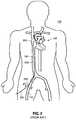
- FIG. 1there is shown a schematic frontal illustration, looking posteriorly from the anterior side of a patient 100 .
- the heart 102is a pump, the outlet of which is the aorta, including the descending aorta 104 , which is a primary artery in the systemic circulation.
- the circulatory systemwhich is connected to the heart 102 further comprises the return, or venous, circulation.
- the venous circulationcomprises the superior vena cava 108 and the inferior vena cava 106 .
- the right and left jugular veins, 110 and 112 , respectively, and the subclavian vein 114are smaller venous vessels with venous blood returning to the superior vena cava 108 .
- the veinscarry blood from the tissues of the body back to the right heart, which then pumps the blood through the lungs and back into the left heart.
- the arteries of the circulatory systemcarry oxygenated blood (not shown) from left ventricle of the heart 102 to the tissues of the body.
- FIG. 2shows that a vascular introduction sheath 204 has been inserted into the right femoral vein 116 via a percutaneous puncture or incision.
- a guidewire 200has been inserted through the introduction sheath 204 and routed up the inferior vena cava 106 to the right atrium 202 , one of the chambers of the heart 102 .
- the left anatomical side of the patient 100is toward the right.
- the guidewire 200has been placed so that it can be used to track a delivery catheter into a region of the heart 102 .
- FIG. 3shows how, after the placement of a guidewire 200 into the left atrium of the patient's heart by known means, a delivery catheter 700 , or sleeve, having an open central bore 704 may be advanced over the guidewire until a distal tip of the guide catheter is positioned in the left atrium.
- the purpose of the delivery catheter 700 shown in FIG. 3is to permit a delivery element to advance and introduce a tool such as a clip, stent, valve, or the like, via a central bore of the guide catheter, into the left atrium for eventual placement in the heart via a puncture in the septum 504 , for example, into the mitral valve 510 .
- Tools such as theseare typically introduced at the distal end of an delivery element.
- FIG. 3shows the extremely tortuous radius of a guide catheter, through which a delivery element must be forced axially, and made to rotate while being forced axially.
- the inventionis a jointed system for delivering a medical device to a target location within a human anatomy.
- the jointed systemcomprises a first segment that is a hollow cylinder and has a proximal end and a distal end, wherein a first flange and a second flange are attached to the distal end and extend distally away from the first segment, further wherein the first flange is positioned diametrically across the first segment opposite the second flange.
- a second segmentis provided, which is a hollow cylinder and has a proximal end and a distal end, wherein a third flange and a fourth flange are attached to the proximal end and extend proximally away from the second segment.
- the third flangeis positioned diametrically across the second segment opposite the fourth flange.
- the distal end of the first segmentis positioned adjacent the proximal end of the second segment such that each of the first flange and the second flange are positioned between the third flange and the fourth flange.
- each of the first flange, the second flange, the third flange, and the fourth flangedefines a circular hole.
- a connector elementwhich has four cylindrical lugs extending radially away from a central point, wherein each lug passes, respectively, through each circular hole, and further wherein the connector element defines at least two separate openings extending in a direction from the distal end of the first segment to the proximal end of the second segment.
- the jointed systemfurther includes at least two wires for controlling a medical device, each wire extending respectively through each separate opening. In some embodiments, the at least two separate openings are four openings in number. In yet further embodiments, the jointed system further includes a guiding catheter having a central bore, wherein the first segment, and the second segment are positioned within the central bore. In alternative embodiments, the first segment includes a cylindrical portion and an external surface which departs from a cylindrical form at a terminal end, wherein an outside surface the first segment slopes towards a central axis of the first segment by a distance D5 towards the axis over a distance D6 along the axis, wherein the ratio of D5:D6 is between 1 ⁇ 5 and 1 ⁇ 4.
- first segmenthas a length of D1 and a diameter of D2, wherein the ratio of D1:D2 is between 1.8 and 2.2.
- first segment and the second segmentare formed from a polymer, and alternatively, of a metal which is preferably stainless steel, elgiloy, or nitinol.
- the inventionis a jointed system for delivering a medical device to a target location within a human anatomy.
- the inventioncomprises a first segment that is a hollow cylinder having a proximal end and a distal end, and a second segment that is a hollow cylinder having a proximal end and a distal end.
- the distal end of the first segmentis positioned adjacent the proximal end of the second segment, and further wherein the first segment is connected to the second segment by a connector element that has four lugs positioned in a single plane, and a first set of two lugs are inserted into holes defined by the first segment and a second set of two lugs are inserted into holes defined by the second segment.
- a sheathis provided which surrounds, and in sliding contact with, the first segment and the second segment.
- the connector elementdefines at least two separate openings extending in a direction from the distal end of the first segment to the proximal end of the second segment.
- the four lugsare positioned at ninety degree intervals around a circumference of the connector element.
- the first segmentincludes a cylindrical portion, and an external surface which departs from a cylindrical form at its proximal end, wherein an outside surface the first segment slopes towards a central axis of the first segment by a distance D5 towards the axis over a distance D6 along the axis, wherein the ratio of D5:D6 is between 1 ⁇ 5 and 1 ⁇ 4.
- the first segmenthas a length of D1 and a diameter of D2, wherein the ratio of D1:D2 is between 1.8 and 2.2.
- FIG. 1is a front view schematic representation of the human venous circulatory system including the heart and the great veins;
- FIG. 2is a front view schematic representation of the human venous circulatory system with a known guidewire routed from the femoral vein into the right atrium.
- FIG. 3is a front view schematic representation of the human venous circulatory system with a guide catheter advanced into the left atrium of a patient's heart, via a septal puncture.
- FIG. 4is a perspective view, in partial cutaway, of aspects of a delivery element having features of the invention.
- FIG. 5is a sectional view taken substantially along the line B-B in FIG. 4 .
- FIG. 6is a perspective view, in partial cutaway, of another embodiment of the delivery element shown in FIG. 4 .
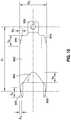
- FIG. 7is a vertical front view of an element of the invention.
- FIG. 8is a vertical side view of the element in FIG. 7 .
- FIG. 9is a schematic view in partial section of a delivery element having features of the invention.
- FIG. 10is a perspective view of a component of a delivery element having features of the invention.
- FIG. 11is a perspective view, in partial cutaway, of the embodiment in FIG. 6 , shown in a bent condition.
- the inventionincludes a jointed system 800 for a delivery element suitable for use in delivering medical repair devices.
- the inventionincludes a first cylindrical segment 802 which is hollow, having a central bore 803 and a second cylindrical segment 804 which is hollow, having a central bore 805 .
- Each of these cylindrical segmentsmay be made from a metal or from a polymer, and may be cut from a parent cylinder using known micro-cutting means such as laser energy and micro-drilling. In other cases cylindrical segments may be constructed of braided or composite shafts or polymer extrusions with any number of internal lumens.
- first cylindrical segment 802is positioned adjacent to, and coaxially aligned with, the second cylindrical segment 804 .
- Each one of the adjacent ends of each segmentis shaped to have a set of two flanges that extend away from each respective segment in a direction parallel with the elongate axis A-A that is shared by the two segments.
- first segment 802has a set of two flanges 802 a , 802 b
- second segment 804has a set of two flanges 804 a , 804 b .
- Each of the two flanges in a setare located on opposite sides (that is, 180 degrees apart) of the associated cylindrical segment.
- the jointed system 800When the jointed system 800 is assembled, the first segment 802 is rotated 90 degrees around the shared axis A-A in relation to the second segment 804 , so that the two sets of flanges fit adjacent one another in a circumferential direction, as seen in FIG. 4 .
- a circular hole 806is drilled into each of the four flanges 802 a , 802 b , 804 a , 804 b .
- Each holeis drilled into each flange in a radial direction with respect to the respective segment, and is aligned with the hole on the opposing flange.
- Known systems for micro-drillingmay be used, because the diameter of the hole 806 may be 0.4 to 1.0 mm, and it should be drilled circular with a constant radius to within a high degree of tolerance, as will become apparent hereafter.
- a connector element 810is provided and introduced between the first segment 802 and the second segment 804 for facilitating their being connected together.
- the connector element 810is, from one view, a planar element ( FIG. 8 ) and has four lugs 812 or pins that extend radially outwardly to an equal radial length away from a common center point.
- the connector element 810has a cruciform shape as seen in FIG. 7 .
- the lugs 812are prepared by known micro-milling technique to produce a cylindrical shape of the same radius in each lug.
- the radius of the lugis selected to be the same (within tolerance) as the radius of the hole 806 drilled into each flange.
- the cruciform element 810defines a plurality of separate openings 814 (four, in the embodiment shown in FIG. 7 ) which will permit the passage of wires 816 (seen in FIGS. 6-9 ) for operating a medical device during implantation once the system has been assembled.
- the objectiveis to insert one of each of the four lugs 812 into one of each of the four holes 806 —to cause the two cylindrical segments 802 , 804 to be connected to each other.
- This actioncan be accomplished by squeezing the first cylindrical segment across a diameter, so that the two flanges on that segment move apart slightly.
- the connector element 810is inserted between the flanges 802 a , 802 b and the lugs 812 are aligned with the holes 806 , so that when the squeezing force is removed, the flanges return to the their normal separation, thereby inserting the lugs 812 into the holes 806 .
- the second cylindrical element 804is squeezed across a diameter to open the space between the opposing flanges 804 a , 804 b .
- the remaining two lugs 812are positioned adjacent and aligned with the remaining holes 806 , whereupon the squeezing force is removed. This causes the segment to resume its normal cylindrical shape, and the lugs 812 to slide into the remaining holes 806 .
- the four lugs of the connector elementare snugly inserted into the four holes of the two segments 802 , 804 and the assembly appears as in FIG. 4 .
- the two segments 802 , 804are joined together by a system that will provide a very high degree of torsional stiffness.
- This high degree of stiffnessarises because the load bearing elements for carrying torsion from the first segment 802 to the second segment 804 comprise the respective lugs and holes.
- These lugs and holesare located at a very large radial distance away from the central axis A-A of the assembly. In fact, they are located at the outer perimeter of the assembly, and this provides a high degree of mechanical advantage in rotating the jointed system.
- the arrangementprovides for a very high level of mobility in the jointed system that arises. If a little lubricant is applied at the holes, the frictional resistance at the joint is very low.
- the presence of the openings 814 in the connector element 810 for receiving control wiresplays an advantageous role in confining any control wires that are selected to extend along the segment bores 803 , 805 .
- the nature of the jointed systemwould present the two sets of flanges 802 a , 802 b and 804 a , 804 b which, when the two segments 802 , 804 are rotated at an angle with respect to each other, would tend to come close to touching each other.
- a control wire passing across the connector element 810 between the two segmentsmay migrate radially outward to a location between two opposing flanges and become entrapped or damaged by the flanges.
- the wiresare kept away from the perimeter of the joint, and are kept from becoming entrapped between the flanges.
- FIG. 9a series of segments may be connected to each other, end to end, as seen in FIG. 9 , to form a delivery element 900 .
- Each connectionincludes a repeating arrangement where a connector element 810 joins one segment to the next.
- Through the openings 814 in each of the connector elementsmay run a series of separate wires 816 which are configured for operating a medical device 820 at the distal end of the series of segments.
- the four lug connectionseach possess: (1) great torsional stiffness, so that there is a high degree of fidelity between rotational movement at the proximal end of the delivery element 900 and rotational movement by the medical device 820 ; (2) great axial stiffness, so that there is a high degree of fidelity between axial movement at the proximal end of the delivery element and axial movement by the medical device 820 ; and (3) great bending flexibility, so that the four lug connection permits near frictionless bending about two axes of rotation simultaneously.
- the four lug connectionsshould only be present within the length of the delivery catheter that remain positioned within the steerable guide catheter throughout the use of the catheter. As a device is advanced forward toward the valve plane or below, if a four lug connection becomes exposed distal to the guide, all control would be lost since there is no bending stiffness in the connection acting on its own. For this reason, an “extendable” dimension at the distal portion of the catheter (just proximal to the device being delivered) should remain rigid without joints so that the exit trajectory of the device is trustworthy during device advancement.
- An important dimension in the overall behavior of the delivery elementis the length of each of the segments. The shorter each segment, the tighter (i.e. smaller) the radius of curvature that the delivery element will be able to follow in going round the curved delivery catheter 700 .
- segments that affects the amount of frictional drag against both rotation and advancement of the delivery element through the delivery catheteris the shape of the outer surface of the segments.
- An improvement that may be imparted to each segmentis to slope the ends of each segment towards the axial centerline of each segment, as seen in FIG. 6 and FIG. 10 .
- segments forming the jointed systemare referred to as 802 ′ and 804 ′. This has the advantage that, when the delivery element 900 is pushed around a corner of the delivery catheter and then advanced along the bore of the delivery catheter 700 , the terminal ends of the segment do not snag into the inner surface of the delivery catheter.
- each segmentmay be described as follows: (1) The ends 830 of each flange slope towards the central axis of the segment at an angle having a slope given by the distance D3 divided by the distance D4, which is preferably between 1 ⁇ 5 and 1 ⁇ 4. D3 is the distance (in a radial direction) by which the outside of the cylindrical form departs from the purely cylindrical, and D4 is the distance (in an axial direction) over which the departure takes place. (2) The outside of surface of each segment, located between the two flanges, also slopes towards the central axis of the segment at an angle having a slope given by the distance D5 divided by the distance D6, which is preferably between 1 ⁇ 5 and 1 ⁇ 4.
- D5is the distance (in a radial direction) by which the outside of the cylindrical form departs from the purely cylindrical
- D6is the distance (in an axial direction) over which the departure takes place.
- the length D1 of each segment in relation to its diameter D2will play an important role in enabling a chain of connected segments to pass around a curved delivery catheter 700 , and to be rotated at the same time.
- the aspect ratio (D1/D2) of each segmentpreferably is in the range of between 1.8 and 2.2.
Landscapes
- Health & Medical Sciences (AREA)
- Cardiology (AREA)
- Life Sciences & Earth Sciences (AREA)
- Veterinary Medicine (AREA)
- General Health & Medical Sciences (AREA)
- Engineering & Computer Science (AREA)
- Biomedical Technology (AREA)
- Heart & Thoracic Surgery (AREA)
- Public Health (AREA)
- Animal Behavior & Ethology (AREA)
- Oral & Maxillofacial Surgery (AREA)
- Transplantation (AREA)
- Vascular Medicine (AREA)
- Pulmonology (AREA)
- Biophysics (AREA)
- Anesthesiology (AREA)
- Hematology (AREA)
- Surgical Instruments (AREA)
- Surgery (AREA)
- Media Introduction/Drainage Providing Device (AREA)
- Nuclear Medicine, Radiotherapy & Molecular Imaging (AREA)
- Pathology (AREA)
- Medical Informatics (AREA)
- Molecular Biology (AREA)
Abstract
Description
Claims (17)
Priority Applications (3)
| Application Number | Priority Date | Filing Date | Title |
|---|---|---|---|
| US15/438,555US10675439B2 (en) | 2017-02-21 | 2017-02-21 | High torsion delivery catheter element |
| PCT/US2018/018862WO2018156524A1 (en) | 2017-02-21 | 2018-02-20 | High torsion delivery catheter element |
| EP18708824.0AEP3585311A1 (en) | 2017-02-21 | 2018-02-20 | High torsion delivery catheter element |
Applications Claiming Priority (1)
| Application Number | Priority Date | Filing Date | Title |
|---|---|---|---|
| US15/438,555US10675439B2 (en) | 2017-02-21 | 2017-02-21 | High torsion delivery catheter element |
Publications (2)
| Publication Number | Publication Date |
|---|---|
| US20180235657A1 US20180235657A1 (en) | 2018-08-23 |
| US10675439B2true US10675439B2 (en) | 2020-06-09 |
Family
ID=61563503
Family Applications (1)
| Application Number | Title | Priority Date | Filing Date |
|---|---|---|---|
| US15/438,555Active2037-07-28US10675439B2 (en) | 2017-02-21 | 2017-02-21 | High torsion delivery catheter element |
Country Status (3)
| Country | Link |
|---|---|
| US (1) | US10675439B2 (en) |
| EP (1) | EP3585311A1 (en) |
| WO (1) | WO2018156524A1 (en) |
Families Citing this family (74)
| Publication number | Priority date | Publication date | Assignee | Title |
|---|---|---|---|---|
| US8652202B2 (en) | 2008-08-22 | 2014-02-18 | Edwards Lifesciences Corporation | Prosthetic heart valve and delivery apparatus |
| US10517719B2 (en) | 2008-12-22 | 2019-12-31 | Valtech Cardio, Ltd. | Implantation of repair devices in the heart |
| US9968452B2 (en) | 2009-05-04 | 2018-05-15 | Valtech Cardio, Ltd. | Annuloplasty ring delivery cathethers |
| US8449599B2 (en) | 2009-12-04 | 2013-05-28 | Edwards Lifesciences Corporation | Prosthetic valve for replacing mitral valve |
| EP3345573B1 (en) | 2011-06-23 | 2020-01-29 | Valtech Cardio, Ltd. | Closure element for use with annuloplasty structure |
| US9011468B2 (en) | 2011-09-13 | 2015-04-21 | Abbott Cardiovascular Systems Inc. | Independent gripper |
| US8945177B2 (en) | 2011-09-13 | 2015-02-03 | Abbott Cardiovascular Systems Inc. | Gripper pusher mechanism for tissue apposition systems |
| US9439763B2 (en) | 2013-02-04 | 2016-09-13 | Edwards Lifesciences Corporation | Prosthetic valve for replacing mitral valve |
| US9622863B2 (en) | 2013-11-22 | 2017-04-18 | Edwards Lifesciences Corporation | Aortic insufficiency repair device and method |
| WO2016090308A1 (en) | 2014-12-04 | 2016-06-09 | Edwards Lifesciences Corporation | Percutaneous clip for repairing a heart valve |
| EP3294219B1 (en) | 2015-05-14 | 2020-05-13 | Edwards Lifesciences Corporation | Heart valve sealing devices and delivery devices therefor |
| US11219746B2 (en) | 2016-03-21 | 2022-01-11 | Edwards Lifesciences Corporation | Multi-direction steerable handles for steering catheters |
| US10835714B2 (en) | 2016-03-21 | 2020-11-17 | Edwards Lifesciences Corporation | Multi-direction steerable handles for steering catheters |
| US10799677B2 (en) | 2016-03-21 | 2020-10-13 | Edwards Lifesciences Corporation | Multi-direction steerable handles for steering catheters |
| US10799676B2 (en) | 2016-03-21 | 2020-10-13 | Edwards Lifesciences Corporation | Multi-direction steerable handles for steering catheters |
| US10799675B2 (en) | 2016-03-21 | 2020-10-13 | Edwards Lifesciences Corporation | Cam controlled multi-direction steerable handles |
| EP3868306A1 (en) | 2016-06-20 | 2021-08-25 | Evalve, Inc. | Transapical removal device |
| US10973638B2 (en) | 2016-07-07 | 2021-04-13 | Edwards Lifesciences Corporation | Device and method for treating vascular insufficiency |
| US10653862B2 (en) | 2016-11-07 | 2020-05-19 | Edwards Lifesciences Corporation | Apparatus for the introduction and manipulation of multiple telescoping catheters |
| US10905554B2 (en) | 2017-01-05 | 2021-02-02 | Edwards Lifesciences Corporation | Heart valve coaptation device |
| EP4613214A2 (en) | 2017-04-18 | 2025-09-10 | Edwards Lifesciences Corporation | Heart valve sealing devices and delivery devices therefor |
| US11224511B2 (en) | 2017-04-18 | 2022-01-18 | Edwards Lifesciences Corporation | Heart valve sealing devices and delivery devices therefor |
| US10799312B2 (en) | 2017-04-28 | 2020-10-13 | Edwards Lifesciences Corporation | Medical device stabilizing apparatus and method of use |
| US10959846B2 (en) | 2017-05-10 | 2021-03-30 | Edwards Lifesciences Corporation | Mitral valve spacer device |
| CA3066361A1 (en) | 2017-06-07 | 2018-12-13 | Shifamed Holdings, Llc | Intravascular fluid movement devices, systems, and methods of use |
| US11051940B2 (en) | 2017-09-07 | 2021-07-06 | Edwards Lifesciences Corporation | Prosthetic spacer device for heart valve |
| US11065117B2 (en) | 2017-09-08 | 2021-07-20 | Edwards Lifesciences Corporation | Axisymmetric adjustable device for treating mitral regurgitation |
| US11040174B2 (en) | 2017-09-19 | 2021-06-22 | Edwards Lifesciences Corporation | Multi-direction steerable handles for steering catheters |
| WO2019094963A1 (en) | 2017-11-13 | 2019-05-16 | Shifamed Holdings, Llc | Intravascular fluid movement devices, systems, and methods of use |
| US10111751B1 (en) | 2018-01-09 | 2018-10-30 | Edwards Lifesciences Corporation | Native valve repair devices and procedures |
| US10076415B1 (en) | 2018-01-09 | 2018-09-18 | Edwards Lifesciences Corporation | Native valve repair devices and procedures |
| FI3964175T3 (en) | 2018-01-09 | 2024-12-03 | Edwards Lifesciences Corp | Native valve repair devices |
| US10973639B2 (en) | 2018-01-09 | 2021-04-13 | Edwards Lifesciences Corporation | Native valve repair devices and procedures |
| US10507109B2 (en) | 2018-01-09 | 2019-12-17 | Edwards Lifesciences Corporation | Native valve repair devices and procedures |
| US10238493B1 (en) | 2018-01-09 | 2019-03-26 | Edwards Lifesciences Corporation | Native valve repair devices and procedures |
| US10105222B1 (en) | 2018-01-09 | 2018-10-23 | Edwards Lifesciences Corporation | Native valve repair devices and procedures |
| US10159570B1 (en) | 2018-01-09 | 2018-12-25 | Edwards Lifesciences Corporation | Native valve repair devices and procedures |
| US10245144B1 (en) | 2018-01-09 | 2019-04-02 | Edwards Lifesciences Corporation | Native valve repair devices and procedures |
| US10136993B1 (en) | 2018-01-09 | 2018-11-27 | Edwards Lifesciences Corporation | Native valve repair devices and procedures |
| US10231837B1 (en) | 2018-01-09 | 2019-03-19 | Edwards Lifesciences Corporation | Native valve repair devices and procedures |
| US10123873B1 (en) | 2018-01-09 | 2018-11-13 | Edwards Lifesciences Corporation | Native valve repair devices and procedures |
| CN117481869A (en) | 2018-01-25 | 2024-02-02 | 爱德华兹生命科学公司 | Delivery system for assisting in recapture and repositioning of replacement valves after deployment |
| CN112004563B (en) | 2018-02-01 | 2024-08-06 | 施菲姆德控股有限责任公司 | Intravascular blood pump and methods of use and manufacture |
| US11389297B2 (en) | 2018-04-12 | 2022-07-19 | Edwards Lifesciences Corporation | Mitral valve spacer device |
| US11207181B2 (en) | 2018-04-18 | 2021-12-28 | Edwards Lifesciences Corporation | Heart valve sealing devices and delivery devices therefor |
| US12161857B2 (en) | 2018-07-31 | 2024-12-10 | Shifamed Holdings, Llc | Intravascular blood pumps and methods of use |
| WO2020073047A1 (en) | 2018-10-05 | 2020-04-09 | Shifamed Holdings, Llc | Intravascular blood pumps and methods of use |
| US10945844B2 (en) | 2018-10-10 | 2021-03-16 | Edwards Lifesciences Corporation | Heart valve sealing devices and delivery devices therefor |
| CN113226223A (en) | 2018-11-20 | 2021-08-06 | 爱德华兹生命科学公司 | Deployment tools and methods for delivering devices to native heart valves |
| CA3118988A1 (en) | 2018-11-21 | 2020-05-28 | Edwards Lifesciences Corporation | Heart valve sealing devices, delivery devices therefor, and retrieval devices |
| CR20210312A (en) | 2018-11-29 | 2021-09-14 | Edwards Lifesciences Corp | Catheterization method and apparatus |
| ES2969252T3 (en) | 2019-02-14 | 2024-05-17 | Edwards Lifesciences Corp | Heart valve sealing devices and delivery devices therefor |
| US11534303B2 (en) | 2020-04-09 | 2022-12-27 | Evalve, Inc. | Devices and systems for accessing and repairing a heart valve |
| WO2021011473A1 (en) | 2019-07-12 | 2021-01-21 | Shifamed Holdings, Llc | Intravascular blood pumps and methods of manufacture and use |
| CA3147410A1 (en) | 2019-07-15 | 2021-01-21 | Evalve, Inc. | Proximal element actuator fixation and release mechanisms |
| JP7566004B2 (en) | 2019-07-15 | 2024-10-11 | エバルブ,インコーポレイティド | Wide clip with non-deforming wings |
| JP7543391B2 (en) | 2019-07-15 | 2024-09-02 | エバルブ,インコーポレイティド | Method of Actuating Individual Proximal Elements |
| US11654275B2 (en) | 2019-07-22 | 2023-05-23 | Shifamed Holdings, Llc | Intravascular blood pumps with struts and methods of use and manufacture |
| US12121713B2 (en) | 2019-09-25 | 2024-10-22 | Shifamed Holdings, Llc | Catheter blood pumps and collapsible blood conduits |
| EP4501393A3 (en) | 2019-09-25 | 2025-04-09 | Shifamed Holdings, LLC | Catheter blood pumps and collapsible pump housings |
| WO2021062265A1 (en) | 2019-09-25 | 2021-04-01 | Shifamed Holdings, Llc | Intravascular blood pump systems and methods of use and control thereof |
| EP4033970B1 (en) | 2019-09-26 | 2024-11-20 | Evalve, Inc. | Systems for intra-procedural cardiac pressure monitoring |
| US11464636B2 (en) | 2019-10-11 | 2022-10-11 | Evalve, Inc. | Repair clip for variable tissue thickness |
| WO2021092107A1 (en) | 2019-11-06 | 2021-05-14 | Evalve, Inc. | Stabilizer for a medical delivery system |
| EP4292546B1 (en) | 2019-11-08 | 2025-04-23 | Evalve, Inc. | Medical device delivery system with locking system |
| US11701229B2 (en) | 2019-11-14 | 2023-07-18 | Evalve, Inc. | Kit with coaptation aid and fixation system and methods for valve repair |
| US11801140B2 (en) | 2019-11-14 | 2023-10-31 | Evalve, Inc. | Catheter assembly with coaptation aid and methods for valve repair |
| EP4072650A4 (en) | 2019-12-11 | 2024-01-10 | Shifamed Holdings, LLC | Descending aorta and vena cava blood pumps |
| US12109115B2 (en) | 2019-12-18 | 2024-10-08 | Evalve, Inc. | Wide clip with deformable width |
| US11628272B2 (en)* | 2020-02-05 | 2023-04-18 | Medtronic Vascular, Inc. | Modular catheter |
| USD1039141S1 (en)* | 2020-04-27 | 2024-08-13 | Acclarent, Inc. | Flex section in shaft for ENT instrument |
| WO2022081328A1 (en) | 2020-10-15 | 2022-04-21 | Evalve, Inc. | Biased distal assemblies with locking mechanism |
| EP4082481B1 (en) | 2021-04-30 | 2024-04-17 | Evalve Inc. | Fixation device having a flexure portion |
| USD1071198S1 (en) | 2023-06-28 | 2025-04-15 | Edwards Lifesciences Corporation | Cradle |
Citations (30)
| Publication number | Priority date | Publication date | Assignee | Title |
|---|---|---|---|---|
| US5042707A (en) | 1990-10-16 | 1991-08-27 | Taheri Syde A | Intravascular stapler, and method of operating same |
| US5386741A (en) | 1993-06-07 | 1995-02-07 | Rennex; Brian G. | Robotic snake |
| US20020062062A1 (en) | 2000-04-03 | 2002-05-23 | Amir Belson | Steerable segmented endoscope and method of insertion |
| US20020082585A1 (en) | 1999-06-15 | 2002-06-27 | Sean Carroll | Defined deflection structure |
| US20030036748A1 (en)* | 2001-06-29 | 2003-02-20 | Intuitive Surgical, Inc. | Surgical tool having positively positionable tendon-actuated multi-disk wrist joint |
| US20030083550A1 (en) | 2001-10-31 | 2003-05-01 | Kunihiko Miyagi | Bent tube and method for manufacturing the same |
| US20050107667A1 (en) | 2003-05-23 | 2005-05-19 | Novare Surgical Systems, Inc. | Hand-actuated device for remote manipulation of a grasping tool |
| US20060111616A1 (en) | 2004-11-24 | 2006-05-25 | Novare Surgical Systems, Inc. | Articulating mechanism components and system for easy assembly and disassembly |
| US20060199999A1 (en)* | 2001-06-29 | 2006-09-07 | Intuitive Surgical Inc. | Cardiac tissue ablation instrument with flexible wrist |
| US20080051703A1 (en) | 1999-04-09 | 2008-02-28 | Evalve, Inc. | Multi-catheter steerable guiding system and methods of use |
| US7338505B2 (en) | 2002-01-09 | 2008-03-04 | Neoguide Systems, Inc. | Apparatus and method for endoscopic colectomy |
| US20080287741A1 (en) | 2007-05-18 | 2008-11-20 | Boston Scientific Scimed, Inc. | Articulating torqueable hollow device |
| US20090099554A1 (en) | 2006-06-20 | 2009-04-16 | Forster David C | Elongate Flexible Torque Instruments And Methods Of Use |
| US7553275B2 (en) | 2004-08-31 | 2009-06-30 | Surgical Solutions Llc | Medical device with articulating shaft |
| US20090171151A1 (en) | 2004-06-25 | 2009-07-02 | Choset Howard M | Steerable, follow the leader device |
| US7637903B2 (en) | 2004-02-09 | 2009-12-29 | Cryocor, Inc. | Catheter articulation segment with alternating cuts |
| US7708102B2 (en) | 2005-09-05 | 2010-05-04 | Denso Corporation | Collision detecting system |
| WO2010149969A1 (en) | 2009-06-24 | 2010-12-29 | Imperial Innovations Limited | Joint arrangement |
| US20110022078A1 (en) | 2009-07-23 | 2011-01-27 | Cameron Dale Hinman | Articulating mechanism |
| US8052607B2 (en) | 2008-04-22 | 2011-11-08 | St. Jude Medical, Atrial Fibrillation Division, Inc. | Ultrasound imaging catheter with pivoting head |
| US20110319898A1 (en)* | 2010-06-24 | 2011-12-29 | O'neil Michael J | Instruments and Methods for Non-Parallel Disc Space Preparation |
| US8096457B1 (en) | 2009-05-05 | 2012-01-17 | Cardica, Inc. | Articulation mechanisms for surgical instrument |
| US20120136350A1 (en) | 2010-10-21 | 2012-05-31 | Medtronic Ardian Luxembourg S.A.R.L. | Catheter apparatuses, systems, and methods for renal neuromodulation |
| US20120190924A1 (en) | 2011-01-21 | 2012-07-26 | Hsiang Te Tseng | Flexible Tubular Interlocking Structure for a Handheld Endoscope |
| US8721591B2 (en) | 2004-04-21 | 2014-05-13 | Acclarent, Inc. | Apparatus and methods for dilating and modifying ostia of paranasal sinuses and other intranasal or paranasal structures |
| US20140135685A1 (en) | 2012-11-13 | 2014-05-15 | Abbott Cardiovascular Systems Inc. | Steerable assembly for surgical catheter |
| US8852112B2 (en) | 2007-06-28 | 2014-10-07 | W. L. Gore & Associates, Inc. | Catheter with deflectable imaging device and bendable electrical conductor |
| US20150226269A1 (en)* | 2012-08-31 | 2015-08-13 | Hino Motors, Ltd. | Method for manufacturing propeller shaft, and propeller shaft |
| WO2016176610A1 (en) | 2015-04-30 | 2016-11-03 | Edwards Lifesciences Cardiaq Llc | Replacement mitral valve, delivery system for replacement mitral valve and methods of use |
| US20170095922A1 (en)* | 2015-10-05 | 2017-04-06 | James Michael LICHT | Medical devices having smoothly articulating multi-cluster joints |
Family Cites Families (5)
| Publication number | Priority date | Publication date | Assignee | Title |
|---|---|---|---|---|
| JP2938486B2 (en)* | 1989-12-28 | 1999-08-23 | 株式会社町田製作所 | Curved tube and manufacturing method thereof |
| US20040215301A1 (en)* | 2003-04-23 | 2004-10-28 | Lokhoff Nicolaas M. | Medical lead with a pivotal tip |
| JP2006068393A (en)* | 2004-09-03 | 2006-03-16 | Olympus Corp | Endoscope |
| CN104053393B (en)* | 2012-04-12 | 2016-12-28 | 奥林巴斯株式会社 | endoscope |
| WO2015161249A1 (en)* | 2014-04-18 | 2015-10-22 | Physcient, Inc. | Methods and devices for soft tissue dissection |
- 2017
- 2017-02-21USUS15/438,555patent/US10675439B2/enactiveActive
- 2018
- 2018-02-20EPEP18708824.0Apatent/EP3585311A1/ennot_activeWithdrawn
- 2018-02-20WOPCT/US2018/018862patent/WO2018156524A1/ennot_activeCeased
Patent Citations (30)
| Publication number | Priority date | Publication date | Assignee | Title |
|---|---|---|---|---|
| US5042707A (en) | 1990-10-16 | 1991-08-27 | Taheri Syde A | Intravascular stapler, and method of operating same |
| US5386741A (en) | 1993-06-07 | 1995-02-07 | Rennex; Brian G. | Robotic snake |
| US20080051703A1 (en) | 1999-04-09 | 2008-02-28 | Evalve, Inc. | Multi-catheter steerable guiding system and methods of use |
| US20020082585A1 (en) | 1999-06-15 | 2002-06-27 | Sean Carroll | Defined deflection structure |
| US20020062062A1 (en) | 2000-04-03 | 2002-05-23 | Amir Belson | Steerable segmented endoscope and method of insertion |
| US20030036748A1 (en)* | 2001-06-29 | 2003-02-20 | Intuitive Surgical, Inc. | Surgical tool having positively positionable tendon-actuated multi-disk wrist joint |
| US20060199999A1 (en)* | 2001-06-29 | 2006-09-07 | Intuitive Surgical Inc. | Cardiac tissue ablation instrument with flexible wrist |
| US20030083550A1 (en) | 2001-10-31 | 2003-05-01 | Kunihiko Miyagi | Bent tube and method for manufacturing the same |
| US7338505B2 (en) | 2002-01-09 | 2008-03-04 | Neoguide Systems, Inc. | Apparatus and method for endoscopic colectomy |
| US20050107667A1 (en) | 2003-05-23 | 2005-05-19 | Novare Surgical Systems, Inc. | Hand-actuated device for remote manipulation of a grasping tool |
| US7637903B2 (en) | 2004-02-09 | 2009-12-29 | Cryocor, Inc. | Catheter articulation segment with alternating cuts |
| US8721591B2 (en) | 2004-04-21 | 2014-05-13 | Acclarent, Inc. | Apparatus and methods for dilating and modifying ostia of paranasal sinuses and other intranasal or paranasal structures |
| US20090171151A1 (en) | 2004-06-25 | 2009-07-02 | Choset Howard M | Steerable, follow the leader device |
| US7553275B2 (en) | 2004-08-31 | 2009-06-30 | Surgical Solutions Llc | Medical device with articulating shaft |
| US20060111616A1 (en) | 2004-11-24 | 2006-05-25 | Novare Surgical Systems, Inc. | Articulating mechanism components and system for easy assembly and disassembly |
| US7708102B2 (en) | 2005-09-05 | 2010-05-04 | Denso Corporation | Collision detecting system |
| US20090099554A1 (en) | 2006-06-20 | 2009-04-16 | Forster David C | Elongate Flexible Torque Instruments And Methods Of Use |
| US20080287741A1 (en) | 2007-05-18 | 2008-11-20 | Boston Scientific Scimed, Inc. | Articulating torqueable hollow device |
| US8852112B2 (en) | 2007-06-28 | 2014-10-07 | W. L. Gore & Associates, Inc. | Catheter with deflectable imaging device and bendable electrical conductor |
| US8052607B2 (en) | 2008-04-22 | 2011-11-08 | St. Jude Medical, Atrial Fibrillation Division, Inc. | Ultrasound imaging catheter with pivoting head |
| US8096457B1 (en) | 2009-05-05 | 2012-01-17 | Cardica, Inc. | Articulation mechanisms for surgical instrument |
| WO2010149969A1 (en) | 2009-06-24 | 2010-12-29 | Imperial Innovations Limited | Joint arrangement |
| US20110022078A1 (en) | 2009-07-23 | 2011-01-27 | Cameron Dale Hinman | Articulating mechanism |
| US20110319898A1 (en)* | 2010-06-24 | 2011-12-29 | O'neil Michael J | Instruments and Methods for Non-Parallel Disc Space Preparation |
| US20120136350A1 (en) | 2010-10-21 | 2012-05-31 | Medtronic Ardian Luxembourg S.A.R.L. | Catheter apparatuses, systems, and methods for renal neuromodulation |
| US20120190924A1 (en) | 2011-01-21 | 2012-07-26 | Hsiang Te Tseng | Flexible Tubular Interlocking Structure for a Handheld Endoscope |
| US20150226269A1 (en)* | 2012-08-31 | 2015-08-13 | Hino Motors, Ltd. | Method for manufacturing propeller shaft, and propeller shaft |
| US20140135685A1 (en) | 2012-11-13 | 2014-05-15 | Abbott Cardiovascular Systems Inc. | Steerable assembly for surgical catheter |
| WO2016176610A1 (en) | 2015-04-30 | 2016-11-03 | Edwards Lifesciences Cardiaq Llc | Replacement mitral valve, delivery system for replacement mitral valve and methods of use |
| US20170095922A1 (en)* | 2015-10-05 | 2017-04-06 | James Michael LICHT | Medical devices having smoothly articulating multi-cluster joints |
Non-Patent Citations (3)
| Title |
|---|
| European Patent Office, International Search Report, dated May 7, 2018, pp. 1-5. |
| International Search Report and Written Opinion dated Apr. 10, 2017 in International Application No. PCT/US2017/016781 ISA, PCT Search Report, p. 1-7. |
| International Search Report dated Jul. 18, 2013 in International Application No. PCT/US2013/038073. |
Also Published As
| Publication number | Publication date |
|---|---|
| WO2018156524A1 (en) | 2018-08-30 |
| US20180235657A1 (en) | 2018-08-23 |
| EP3585311A1 (en) | 2020-01-01 |
Similar Documents
| Publication | Publication Date | Title |
|---|---|---|
| US10675439B2 (en) | High torsion delivery catheter element | |
| US11246705B2 (en) | System and method for implant delivery | |
| US10390950B2 (en) | Flexible catheters and methods of forming same | |
| US20220168544A1 (en) | Multi-Directional Steerable Catheter | |
| US11116636B2 (en) | Device for the deployment of a system of guide wires within a cardiac chamber for implanting a prosthetic heart valve | |
| EP3481337B1 (en) | Expandable sheath and methods of using the same | |
| ES2977933T3 (en) | Addressable delivery system for mitral valve replacement | |
| US10932905B2 (en) | Introducer sheath having expandable portions | |
| US10751177B2 (en) | Flexible catheter and methods of forming same | |
| US10631980B2 (en) | Expandable introducer sheath having a steering mechanism | |
| KR102280752B1 (en) | Prosthetic system for heart valve replacement | |
| EP2922501B1 (en) | Device for the deployment of a system of guide wires within a cardiac chamber for implanting a prosthetic heart valve | |
| US9532871B2 (en) | Delivery system deflection mechanism | |
| US10123871B2 (en) | Implant capsule and implant delivery system | |
| US20180303609A1 (en) | Catheter-based delivery device having segment with non-uniform width helical spine | |
| US10052456B1 (en) | Flexible catheter | |
| US12127939B2 (en) | Catheter lumen lubricant | |
| US20250235192A1 (en) | Aortic leaflet crossing systems | |
| EP3860531B1 (en) | Expandable introducer sheath |
Legal Events
| Date | Code | Title | Description |
|---|---|---|---|
| AS | Assignment | Owner name:ABBOTT CARDIOVASCULAR SYSTEMS INC., CALIFORNIA Free format text:ASSIGNMENT OF ASSIGNORS INTEREST;ASSIGNOR:ABUNASSAR, CHAD;REEL/FRAME:041327/0300 Effective date:20170125 | |
| STPP | Information on status: patent application and granting procedure in general | Free format text:RESPONSE TO NON-FINAL OFFICE ACTION ENTERED AND FORWARDED TO EXAMINER | |
| STPP | Information on status: patent application and granting procedure in general | Free format text:NON FINAL ACTION MAILED | |
| STPP | Information on status: patent application and granting procedure in general | Free format text:RESPONSE TO NON-FINAL OFFICE ACTION ENTERED AND FORWARDED TO EXAMINER | |
| STPP | Information on status: patent application and granting procedure in general | Free format text:FINAL REJECTION MAILED | |
| STPP | Information on status: patent application and granting procedure in general | Free format text:RESPONSE AFTER FINAL ACTION FORWARDED TO EXAMINER | |
| STPP | Information on status: patent application and granting procedure in general | Free format text:NOTICE OF ALLOWANCE MAILED -- APPLICATION RECEIVED IN OFFICE OF PUBLICATIONS | |
| STPP | Information on status: patent application and granting procedure in general | Free format text:PUBLICATIONS -- ISSUE FEE PAYMENT VERIFIED | |
| STCF | Information on status: patent grant | Free format text:PATENTED CASE | |
| MAFP | Maintenance fee payment | Free format text:PAYMENT OF MAINTENANCE FEE, 4TH YEAR, LARGE ENTITY (ORIGINAL EVENT CODE: M1551); ENTITY STATUS OF PATENT OWNER: LARGE ENTITY Year of fee payment:4 |