US10675134B2 - Bladder management systems - Google Patents
Bladder management systemsDownload PDFInfo
- Publication number
- US10675134B2 US10675134B2US15/877,228US201815877228AUS10675134B2US 10675134 B2US10675134 B2US 10675134B2US 201815877228 AUS201815877228 AUS 201815877228AUS 10675134 B2US10675134 B2US 10675134B2
- Authority
- US
- United States
- Prior art keywords
- mating structure
- bladder
- catheter
- valve
- mating
- Prior art date
- Legal status (The legal status is an assumption and is not a legal conclusion. Google has not performed a legal analysis and makes no representation as to the accuracy of the status listed.)
- Active, expires
Links
- 238000000605extractionMethods0.000claimsabstractdescription34
- 238000003780insertionMethods0.000claimsabstractdescription28
- 230000037431insertionEffects0.000claimsabstractdescription28
- 230000013011matingEffects0.000claimsdescription44
- 239000012530fluidSubstances0.000abstractdescription13
- 230000002485urinary effectEffects0.000abstractdescription6
- 230000004064dysfunctionEffects0.000abstract1
- 210000002700urineAnatomy0.000description30
- 238000000034methodMethods0.000description15
- 210000003708urethraAnatomy0.000description12
- 239000000463materialSubstances0.000description10
- 230000000007visual effectEffects0.000description10
- 230000007774longtermEffects0.000description8
- 230000004048modificationEffects0.000description7
- 238000012986modificationMethods0.000description7
- 239000000523sampleSubstances0.000description7
- 238000005516engineering processMethods0.000description5
- 230000007704transitionEffects0.000description5
- 239000004615ingredientSubstances0.000description4
- 208000014674injuryDiseases0.000description4
- 230000007246mechanismEffects0.000description4
- 208000000693Neurogenic Urinary BladderDiseases0.000description3
- 206010029279Neurogenic bladderDiseases0.000description3
- 230000005540biological transmissionEffects0.000description3
- 238000004891communicationMethods0.000description3
- 230000006870functionEffects0.000description3
- 238000012545processingMethods0.000description3
- 238000012360testing methodMethods0.000description3
- 230000008733traumaEffects0.000description3
- 238000002604ultrasonographyMethods0.000description3
- 208000019206urinary tract infectionDiseases0.000description3
- 229920001621AMOLEDPolymers0.000description2
- 241001465754MetazoaSpecies0.000description2
- 238000004458analytical methodMethods0.000description2
- 230000008901benefitEffects0.000description2
- 230000001413cellular effectEffects0.000description2
- 238000006243chemical reactionMethods0.000description2
- 239000004020conductorSubstances0.000description2
- 238000012790confirmationMethods0.000description2
- 230000006378damageEffects0.000description2
- 238000010586diagramMethods0.000description2
- 230000036541healthEffects0.000description2
- 230000001965increasing effectEffects0.000description2
- 230000006698inductionEffects0.000description2
- 238000010801machine learningMethods0.000description2
- 239000000696magnetic materialSubstances0.000description2
- 238000005259measurementMethods0.000description2
- 230000003287optical effectEffects0.000description2
- 210000000056organAnatomy0.000description2
- 239000007787solidSubstances0.000description2
- 238000001228spectrumMethods0.000description2
- 239000003381stabilizerSubstances0.000description2
- 101000934888Homo sapiens Succinate dehydrogenase cytochrome b560 subunit, mitochondrialProteins0.000description1
- 206010021639IncontinenceDiseases0.000description1
- 239000004677NylonSubstances0.000description1
- 206010033799ParalysisDiseases0.000description1
- 241000405070PercophidaeSpecies0.000description1
- 206010071368Psychological traumaDiseases0.000description1
- 102100025393Succinate dehydrogenase cytochrome b560 subunit, mitochondrialHuman genes0.000description1
- 229920006362Teflon®Polymers0.000description1
- 208000027418Wounds and injuryDiseases0.000description1
- 210000001015abdomenAnatomy0.000description1
- 210000003484anatomyAnatomy0.000description1
- 230000003466anti-cipated effectEffects0.000description1
- 238000005452bendingMethods0.000description1
- 239000003990capacitorSubstances0.000description1
- 230000008859changeEffects0.000description1
- 239000000470constituentSubstances0.000description1
- 230000008878couplingEffects0.000description1
- 238000010168coupling processMethods0.000description1
- 238000005859coupling reactionMethods0.000description1
- 238000007405data analysisMethods0.000description1
- 230000003247decreasing effectEffects0.000description1
- 238000012217deletionMethods0.000description1
- 230000037430deletionEffects0.000description1
- 238000011161developmentMethods0.000description1
- 238000006073displacement reactionMethods0.000description1
- 230000002996emotional effectEffects0.000description1
- 230000007274generation of a signal involved in cell-cell signalingEffects0.000description1
- 238000002513implantationMethods0.000description1
- 230000001939inductive effectEffects0.000description1
- 208000015181infectious diseaseDiseases0.000description1
- 229920000126latexPolymers0.000description1
- 239000004816latexSubstances0.000description1
- 239000004973liquid crystal related substanceSubstances0.000description1
- 239000000203mixtureSubstances0.000description1
- 229910001000nickel titaniumInorganic materials0.000description1
- HLXZNVUGXRDIFK-UHFFFAOYSA-Nnickel titaniumChemical compound[Ti].[Ti].[Ti].[Ti].[Ti].[Ti].[Ti].[Ti].[Ti].[Ti].[Ti].[Ni].[Ni].[Ni].[Ni].[Ni].[Ni].[Ni].[Ni].[Ni].[Ni].[Ni].[Ni].[Ni].[Ni]HLXZNVUGXRDIFK-UHFFFAOYSA-N0.000description1
- 229920001778nylonPolymers0.000description1
- 244000052769pathogenSpecies0.000description1
- 210000003899penisAnatomy0.000description1
- 229920001296polysiloxanePolymers0.000description1
- 229920002635polyurethanePolymers0.000description1
- 239000004814polyurethaneSubstances0.000description1
- 229920000915polyvinyl chloridePolymers0.000description1
- 230000008569processEffects0.000description1
- 210000002307prostateAnatomy0.000description1
- 230000008707rearrangementEffects0.000description1
- 230000004044responseEffects0.000description1
- 230000000284resting effectEffects0.000description1
- 238000012552reviewMethods0.000description1
- 210000004706scrotumAnatomy0.000description1
- 239000004065semiconductorSubstances0.000description1
- 230000035807sensationEffects0.000description1
- 239000012781shape memory materialSubstances0.000description1
- 229910001220stainless steelInorganic materials0.000description1
- 230000003068static effectEffects0.000description1
- 238000006467substitution reactionMethods0.000description1
- 208000024891symptomDiseases0.000description1
- 230000032258transportEffects0.000description1
- 210000001635urinary tractAnatomy0.000description1
- 230000003202urodynamic effectEffects0.000description1
- 239000011800void materialSubstances0.000description1
Images


Classifications
- A—HUMAN NECESSITIES
- A61—MEDICAL OR VETERINARY SCIENCE; HYGIENE
- A61F—FILTERS IMPLANTABLE INTO BLOOD VESSELS; PROSTHESES; DEVICES PROVIDING PATENCY TO, OR PREVENTING COLLAPSING OF, TUBULAR STRUCTURES OF THE BODY, e.g. STENTS; ORTHOPAEDIC, NURSING OR CONTRACEPTIVE DEVICES; FOMENTATION; TREATMENT OR PROTECTION OF EYES OR EARS; BANDAGES, DRESSINGS OR ABSORBENT PADS; FIRST-AID KITS
- A61F2/00—Filters implantable into blood vessels; Prostheses, i.e. artificial substitutes or replacements for parts of the body; Appliances for connecting them with the body; Devices providing patency to, or preventing collapsing of, tubular structures of the body, e.g. stents
- A61F2/0004—Closure means for urethra or rectum, i.e. anti-incontinence devices or support slings against pelvic prolapse
- A61F2/0022—Closure means for urethra or rectum, i.e. anti-incontinence devices or support slings against pelvic prolapse placed deep in the body opening
- A61F2/0027—Closure means for urethra or rectum, i.e. anti-incontinence devices or support slings against pelvic prolapse placed deep in the body opening inflatable
- A—HUMAN NECESSITIES
- A61—MEDICAL OR VETERINARY SCIENCE; HYGIENE
- A61F—FILTERS IMPLANTABLE INTO BLOOD VESSELS; PROSTHESES; DEVICES PROVIDING PATENCY TO, OR PREVENTING COLLAPSING OF, TUBULAR STRUCTURES OF THE BODY, e.g. STENTS; ORTHOPAEDIC, NURSING OR CONTRACEPTIVE DEVICES; FOMENTATION; TREATMENT OR PROTECTION OF EYES OR EARS; BANDAGES, DRESSINGS OR ABSORBENT PADS; FIRST-AID KITS
- A61F2/00—Filters implantable into blood vessels; Prostheses, i.e. artificial substitutes or replacements for parts of the body; Appliances for connecting them with the body; Devices providing patency to, or preventing collapsing of, tubular structures of the body, e.g. stents
- A61F2/0004—Closure means for urethra or rectum, i.e. anti-incontinence devices or support slings against pelvic prolapse
- A61F2/0022—Closure means for urethra or rectum, i.e. anti-incontinence devices or support slings against pelvic prolapse placed deep in the body opening
- A—HUMAN NECESSITIES
- A61—MEDICAL OR VETERINARY SCIENCE; HYGIENE
- A61F—FILTERS IMPLANTABLE INTO BLOOD VESSELS; PROSTHESES; DEVICES PROVIDING PATENCY TO, OR PREVENTING COLLAPSING OF, TUBULAR STRUCTURES OF THE BODY, e.g. STENTS; ORTHOPAEDIC, NURSING OR CONTRACEPTIVE DEVICES; FOMENTATION; TREATMENT OR PROTECTION OF EYES OR EARS; BANDAGES, DRESSINGS OR ABSORBENT PADS; FIRST-AID KITS
- A61F2/00—Filters implantable into blood vessels; Prostheses, i.e. artificial substitutes or replacements for parts of the body; Appliances for connecting them with the body; Devices providing patency to, or preventing collapsing of, tubular structures of the body, e.g. stents
- A61F2/02—Prostheses implantable into the body
- A61F2/48—Operating or control means, e.g. from outside the body, control of sphincters
- A61F2002/48—
- A—HUMAN NECESSITIES
- A61—MEDICAL OR VETERINARY SCIENCE; HYGIENE
- A61F—FILTERS IMPLANTABLE INTO BLOOD VESSELS; PROSTHESES; DEVICES PROVIDING PATENCY TO, OR PREVENTING COLLAPSING OF, TUBULAR STRUCTURES OF THE BODY, e.g. STENTS; ORTHOPAEDIC, NURSING OR CONTRACEPTIVE DEVICES; FOMENTATION; TREATMENT OR PROTECTION OF EYES OR EARS; BANDAGES, DRESSINGS OR ABSORBENT PADS; FIRST-AID KITS
- A61F2210/00—Particular material properties of prostheses classified in groups A61F2/00 - A61F2/26 or A61F2/82 or A61F9/00 or A61F11/00 or subgroups thereof
- A61F2210/009—Particular material properties of prostheses classified in groups A61F2/00 - A61F2/26 or A61F2/82 or A61F9/00 or A61F11/00 or subgroups thereof magnetic
- A—HUMAN NECESSITIES
- A61—MEDICAL OR VETERINARY SCIENCE; HYGIENE
- A61F—FILTERS IMPLANTABLE INTO BLOOD VESSELS; PROSTHESES; DEVICES PROVIDING PATENCY TO, OR PREVENTING COLLAPSING OF, TUBULAR STRUCTURES OF THE BODY, e.g. STENTS; ORTHOPAEDIC, NURSING OR CONTRACEPTIVE DEVICES; FOMENTATION; TREATMENT OR PROTECTION OF EYES OR EARS; BANDAGES, DRESSINGS OR ABSORBENT PADS; FIRST-AID KITS
- A61F2220/00—Fixations or connections for prostheses classified in groups A61F2/00 - A61F2/26 or A61F2/82 or A61F9/00 or A61F11/00 or subgroups thereof
- A61F2220/0025—Connections or couplings between prosthetic parts, e.g. between modular parts; Connecting elements
- A61F2220/0033—Connections or couplings between prosthetic parts, e.g. between modular parts; Connecting elements made by longitudinally pushing a protrusion into a complementary-shaped recess, e.g. held by friction fit
- A—HUMAN NECESSITIES
- A61—MEDICAL OR VETERINARY SCIENCE; HYGIENE
- A61F—FILTERS IMPLANTABLE INTO BLOOD VESSELS; PROSTHESES; DEVICES PROVIDING PATENCY TO, OR PREVENTING COLLAPSING OF, TUBULAR STRUCTURES OF THE BODY, e.g. STENTS; ORTHOPAEDIC, NURSING OR CONTRACEPTIVE DEVICES; FOMENTATION; TREATMENT OR PROTECTION OF EYES OR EARS; BANDAGES, DRESSINGS OR ABSORBENT PADS; FIRST-AID KITS
- A61F2250/00—Special features of prostheses classified in groups A61F2/00 - A61F2/26 or A61F2/82 or A61F9/00 or A61F11/00 or subgroups thereof
- A61F2250/0001—Means for transferring electromagnetic energy to implants
- A61F2250/0002—Means for transferring electromagnetic energy to implants for data transfer
- A—HUMAN NECESSITIES
- A61—MEDICAL OR VETERINARY SCIENCE; HYGIENE
- A61F—FILTERS IMPLANTABLE INTO BLOOD VESSELS; PROSTHESES; DEVICES PROVIDING PATENCY TO, OR PREVENTING COLLAPSING OF, TUBULAR STRUCTURES OF THE BODY, e.g. STENTS; ORTHOPAEDIC, NURSING OR CONTRACEPTIVE DEVICES; FOMENTATION; TREATMENT OR PROTECTION OF EYES OR EARS; BANDAGES, DRESSINGS OR ABSORBENT PADS; FIRST-AID KITS
- A61F2250/00—Special features of prostheses classified in groups A61F2/00 - A61F2/26 or A61F2/82 or A61F9/00 or A61F11/00 or subgroups thereof
- A61F2250/0003—Special features of prostheses classified in groups A61F2/00 - A61F2/26 or A61F2/82 or A61F9/00 or A61F11/00 or subgroups thereof having an inflatable pocket filled with fluid, e.g. liquid or gas
- A—HUMAN NECESSITIES
- A61—MEDICAL OR VETERINARY SCIENCE; HYGIENE
- A61F—FILTERS IMPLANTABLE INTO BLOOD VESSELS; PROSTHESES; DEVICES PROVIDING PATENCY TO, OR PREVENTING COLLAPSING OF, TUBULAR STRUCTURES OF THE BODY, e.g. STENTS; ORTHOPAEDIC, NURSING OR CONTRACEPTIVE DEVICES; FOMENTATION; TREATMENT OR PROTECTION OF EYES OR EARS; BANDAGES, DRESSINGS OR ABSORBENT PADS; FIRST-AID KITS
- A61F2250/00—Special features of prostheses classified in groups A61F2/00 - A61F2/26 or A61F2/82 or A61F9/00 or A61F11/00 or subgroups thereof
- A61F2250/0004—Special features of prostheses classified in groups A61F2/00 - A61F2/26 or A61F2/82 or A61F9/00 or A61F11/00 or subgroups thereof adjustable
- A61F2250/0013—Special features of prostheses classified in groups A61F2/00 - A61F2/26 or A61F2/82 or A61F9/00 or A61F11/00 or subgroups thereof adjustable for adjusting fluid pressure
Definitions
- This disclosuregenerally relates to bladder management systems, and in particular, wireless sensors and urinary catheters.
- a device that alerts them the amount of urine currently in their bladdercan allow individuals to more accurately determine the timing to release the urine stored in their bladder instead of being required to utilize a time schedule.
- the present technologyrelates to systems and method for controlling the urinary system and, in particular, long-term use device for bladder management and awareness regarding bladder fullness.
- FIG. 1shows a generalized schematic drawing of a sample bladder management system.
- FIG. 2shows a generalized schematic drawing of a sample bladder management system using a signal generating sensor.
- FIGS. 3 and 4schematically show different embodiments of sensors used in the bladder management system.
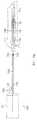
- FIG. 5shows a schematic drawing of a bladder management system used in a male urinary control system.
- FIG. 6Ashows a schematic drawing of an embodiment of the catheter portion of the bladder management system of FIG. 1 .
- FIG. 6Bshows an enlarged view of a valve portion of the catheter of FIG. 6A .
- FIG. 6Cshows a cross-section view of the valve portion of FIG. 6B across the line a-b.
- FIG. 6Dshows an enlarged view of a retaining portion of the catheter of FIG. 6A .
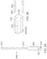
- FIG. 7Ashows a schematic drawing of an embodiment of an extraction device.
- FIG. 7Bshows a schematic drawing of an embodiment of a thruster tip of the extraction device of FIG. 7A .
- FIG. 8Ashows a schematic drawing of an embodiment of an insertion device and the catheter.
- FIG. 8Bshows a schematic drawing of an embodiment of a mating lip of the insertion device of FIG. 8A .
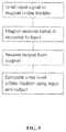
- FIG. 9is a functional block diagram which illustrates the operation of a sample sound sensor system.
- embodiments of systemsthat can be used for bladder management, specifically bladder management for Neurogenic Bladder in a patient.
- embodiments of the systemcan be used to sense metrics that can be used to determine the amount of urine inside a person's, or an animal's, bladders and/or the pressure of urine in the bladder.
- the disclosed systemscan be used for fluid flow control and sensing for other bodily organs as well, and the particular bodily organ described is not limiting.
- the bladder managementcan be based on, for example, characteristics of the urine such as pH level, quantity, volume, pressure, urine constituents, color, odor, turbidity, density, possible pathogens, etc.
- Bladder managementcan also be based on the dimension of the urethra such as circumference or diameter, pressure of urine inside the bladder, so forth and the particular example used for bladder management are not limiting.
- the term “user”is intended to include any person trained and able to perform the procedure, including the patient, doctor, caregiver, nurse, etc.
- the term “patient” and “individual”are intended to be interchangeable.
- bodyused herein is defined as “an animate body” including human, animal, and the like.
- FIG. 1shows a generalized schematic drawing of a sample bladder management system.
- a bladder management system 100can comprise a body.
- the bodycan be a long-term use catheter 105 .
- the catheter 105can be shaped and sized to be introduced into the bladder 110 of a patient.
- the catheter 105can be fully-internal to the body of the patient.
- the catheter 105can comprise a sensor 115 and a valve 120 .
- the catheter 105can further comprise a processor 125 and a power source 130 .
- the bladder management system 100can comprise a computing device 135 , and the processor 125 can be configured to communicate with the computing device 135 .
- the processor 125can communicate with the computing device using wireless transmission 140 .
- the computing device 135can be a mobile phone.
- the bladder management system 100can comprise an external powering system 145 .
- the external powering system 145can be configured to transmit energy to the catheter 105 .
- the power source 130can be a battery or capacitor, and the external powering system 145 can charge the power source 130 through inductive or wireless means.
- the external powering system 145may also utilize energy in other bands of the spectrum (SONAR, Acoustic, Ultrasound, RF, etc) to transmit data that the external unit can sense to extrapolate information about the condition, volume, pressure, or other characteristics of urine in the bladder and also overall bladder health.
- SONARAcoustic, Ultrasound, RF, etc
- the sensor 115can be used to measure the level of urine 155 in the bladder 110 .
- the sensor 115can be placed along the body of the catheter 105 .
- the sensor 115can be inductively and capacitively coupled to the processor 125 .
- the processor 125can be configured to receive an input from the sensor 115 and produce an output that can be used for bladder management.
- the processor 125can receive data from the sensor 115 , and the output from the processor 125 can be used to alert the user about the characteristics of urine and bladder.
- This external systemmay also be used to open or close the valve 120 .
- the valve 120can be in a fluid communication with the catheter 105 .
- the valve 120can be configured to restrict or allow flow of fluid from within the bladder 110 .
- the valve 120can be positioned within a portion of the catheter 105 along the urethra.
- the power source 130can be inductively and capacitively coupled with the processor 125 and/or the external powering system 145 .
- the power source 130can also be coupled with the valve 120 .
- the power source 130can be used, for example, to supply the processor with the power to send or receive information from the computing device 135 .
- the power source 130can be coupled with the valve 120 and be used to supply the power required to open or close the valve 120 .
- the external powering system 145can be connected to an AC outlet and/or utilize DC current from other sources.
- the power source 130can be rechargeable.
- the power source 130can be configured to last for an approximate 1-36 months of usage.
- the power source 130is a battery that can be configured to receive an electric charge from an external powering system 145 via wireless recharging technology similar to what is currently available in other devices as Commercial Off The Shelf (COTS) application for wireless induction charging.
- COTSCommercial Off The Shelf
- the external powering system 145can comprise a charging pod.
- the charging podcan be plugged into an alternating current (AC) outlet.
- ACalternating current
- the power source 130 in the catheter 105can recharge through magnetic induction technology, for example.
- the computing device 135can have a software which can be used to interpret the values sent from the sensor 115 .
- the sensor 115is a pressure sensor and the computing device 135 can be used to alert a user about when their bladder is likely to contract and void.
- the urine 155 amounts inside the bladdercan be calibrated by feedback from the individual user after insertion or implantation.
- the sensorcan use other spectrums of energy, to include acoustics, to determine the fullness or volume of urine in the bladder. Different types of sensors can be embedded on the catheter to determine important metrics of bladder health including pH, volume, pressure, etc. In some embodiments, this can be accomplished through software that analyzes the sensor 115 response and utilizes machine learning algorithms to predict and interpret this data.
- the sensor 115 devicecan utilize basic wireless transmission protocol to wirelessly send data to a computing device 135 with the control software on it. This can be accomplished in a manner similar to Bluetooth, 802.11 WiFi, SONAR, UltraSound, MedRadio or other wireless communications protocols.
- the sensor 115can determine the pressure of urine 155 within the bladder 110 and send a signal to the processor 125 .
- the processor 125sends information on pressure level in the bladder 110 to the computing device 135 .
- the computing device 135uses a software, determines whether urine 155 needs to be drained from the bladder 110 .
- the computing device 135will also notify the user to drain urine from the bladder.
- the usercan actuate the valve 120 which will allow urine 155 to leave the bladder 110 .
- the sensor 115can be used to determine when urine has been sufficiently drained from the bladder 110 , such as by determining that the pressure level within the bladder 110 has dropped below a certain level. This information can be used to close the valve 120 and halt the flow of urine 155 from leaving the bladder 110 .
- This sensing technologyis not limited to pressure, and in some embodiments, other metrics can be used to make decisions with clinical impact.
- the catheter 105can be used to determine various conditions within the bladder 110 .
- the sensor 115can be a pH sensor, an ultrasonic sensor, a displacement sensor, acoustic sensor, etc. Different types and combinations of sensors can be used.
- the catheter 105can comprise a pH sensor and a pressure sensor.
- the valve 120can be configured to increase or decrease the flow rate of urine.
- the valvecan have varying degree of valve opening.
- the valve 120 openingcan be configured to dilate and/or expand in order to increase the volumetric flow rate of urine leaving the bladder 110 .
- a pin valvecan be used.
- This valve 120can also be configured to be actuated by the pressure of urine 155 in the bladder 110 .
- a bladder management system 200can comprise a signal-generating sensor 205 .
- the bladder management system 200can comprise a valve 210 , an external actuator 230 , the signal-generating sensor 205 within a catheter 215 , and an external computing device 240 .
- the signal generating sensor 205can be an LC resonant sensor, an RFID device, or a speaker.
- the system 200can further comprise a microphone and/or an amplifier.
- the valve 210can be configured to open and close using an external valve actuator 230 .
- the external computing device 240can be used to send and receive signals 225 to and from the signal-generating sensor 205 .
- the external computing device 240can be programmed to interpret the signal 225 to indicate condition within a patient's bladder 220 .
- the usercan use the external computing device 240 to generate a signal 225 .
- the sensor 205can receive the signal 225 from the external computing device 240 and generate a return signal 225 that can be analyzed and interpreted to determine metrics about the condition of the bladder and/or urine within the bladder (e.g. volume, pressure, pH level, etc.).
- the computing device 240can display the desired information to the user or can be cataloged for further review and analysis. In some embodiments, this data may be used to send an alert or notify the user or caregiver based on either pre-determined settings or through machine learning algorithms and/or advanced data analysis techniques.
- the computing device 240can receive signal from the sensor 205 that can be interpreted to determine the volume of urine 235 in the bladder 220 .
- an algorithmcan be used to determine the pressure within the bladder 220 based on relationships with the volume of the bladder 220 . Based on the information available or the notification provided, the user can manually open the valve 210 using the external actuator 230 .
- the sensor 205can be configured to change its mechanical properties (e.g. color, size, shape, etc.) based on pressure changes inside the bladder 220 .
- the usercan use an external device to detect changes in mechanical properties of the sensor 205 by, for example, sending and/or receiving sound waves, light waves, etc.
- the internal sensor 205can function without a power source. By constructing the sensor 205 in a specific manner the external unit can observe changes in the resonant frequency characteristics.
- the catheter 215can comprise a computing device 240 .
- a computing device 240can be coupled with the sensor 205 and use a software algorithm to determine urine 235 amount inside the bladder 220 based on data read from the sensor 205 .
- the usercan use an external device that can exchange information with the computing device 240 coupled with the sensor 205 .
- the computing device 240can be linked to an external database.
- an external database having patient datacan be used with the computing device 240 to monitor the patient condition and manage bladder 220 by using data that has been collected and aggregated from other patients and sources.
- a databasecan catalog the dataset that will allow for analysis and algorithm development to improve accuracy and support predictive analytics.
- sample embodiments of the devicecan comprise a catheter 300 , 400 having a proximal end 305 , 405 .
- the catheter 300 , 400can comprise a lumen 310 , 410 having a retaining portion 315 , 415 near the proximal end 305 , 405 .
- the catheter 300 , 400can house a sensor 320 , 420 .
- the sensor 420can comprise a radio unit 425 .
- the radio unit 425can be a transceiver.
- the radio unit 425can comprise a microphone.
- the radio unit 425can be wirelessly coupled to the sensor 420 via different means, including inductive-capacitive coupling or energy transmission in other mediums such as SONAR, UltraSound, Microwave, etc.
- the retaining portion 315 , 415can be configured to transition from an expanded configuration as shown in FIGS. 3-4 to a collapsed configuration shown in FIG. 8A .
- the retaining portion 315 , 415can be a malecot anchor having a plurality of wings.
- the retaining portion 315 , 415can retain and anchor the catheter 300 , 400 within the bladder.
- the catheterIn the collapsed configuration, the catheter can be received within and passed through the bladder neck and urethra without causing trauma to the urethra or significant modification to the human anatomy.
- the catheter 300 , 400which includes the sensor 320 , 420 can perform one or more of the following: measure important metrics of urine and the bladder; wirelessly relay this data to an external device; allow a mechanical valve to open upon user input; be semi-permanent, e.g. allowing long-term use and/or extended wear; be inserted via minimally invasive means; utilize wireless recharging or powering technology for the sensor 320 , 420 or power storage unit; and be removed when the user wishes to remove the catheter.
- the catheter 500can be fully-internal, meaning the catheter 500 is not visible to the naked eye from the exterior, once the catheter 500 is inside the patient's body.
- the fully-internal catheter 500can comprise a proximal portion 505 and a distal portion 510 .
- the proximal portion 505can comprise a retaining portion 515 and a sensor 520 .
- the catheter 500can comprise a lumen 525 .
- the distal portion 510can comprise a valve 530 .
- the sensor 520can be placed proximal to the retaining portion 515 .
- the sensor 520can be configured to communicate with an external computing device 535 .
- the computing device 535is a mobile phone.
- the external computing device 535may be a transceiver that is able to receive and relay these signals to other devices.
- the valve 530can comprise a mating structure 540 .
- the mating structure 540can be configured to mate with a corresponding structure of a catheter insertion device and/or that of an extraction device.
- the urine in the bladder 550can be voided when the user utilizes an external actuator 545 to open the valve 530 and allows the urine to travel through the urethra 560 .
- This signalcan be controlled by the user through the use of an external computing device 535 .
- the valve 530can comprise a magnetic ball valve, and the external actuator 545 car, comprise a magnet.
- this external actuator 545can be a combination of electronic control that may utilize an electromagnet to open the valve 530 .
- a usercan place the external actuator 545 near the valve 530 , e.g. on the skin of patient between the scrotum and the shaft of the penis, to open the valve 530 .
- the valve 530can be closed when the actuator 545 is away from the location of the valve 530 inside the patient's body.
- the valve 530can be closed when the actuator is inside a patient's side pocket.
- the catheter 500can be constructed in a shape and of a material that is conducive to entry utilizing a medical device, such as an insertion device 700 shown in FIGS. 7A and 7B , that will enter through the urinary tract.
- a medical devicesuch as an insertion device 700 shown in FIGS. 7A and 7B
- the catheter 500may be constructed of a material similar to other existing intermittent catheters on the market (such as PVC, Latex, Silicone, Polyurethane or any blend of these materials).
- the catheter 500once inside the bladder 550 , can comprise a retaining portion 515 that can fix the catheter 500 to the wall of the bladder 550 .
- the senor 520can be placed distal to the retaining portion 515 .
- the sensor 520can be coupled to the valve 530 .
- the valve 530can comprise an internal actuator.
- the valve 530can be configured such that an external computing device 535 can be used to open or close the valve 530 using a signal.
- a valve 530can be placed in the proximal portion 505 of the catheter.
- the valve 530can be placed on the neck of the bladder 550 .
- the catheter 500can comprise a retaining portion 515 along a midsection or distal end of the body.
- the catheter 500can be configured such that the retaining portion 515 is placed on or near the prostate 555 or along the urethra 560 of the patient, instead of within the bladder 550 of the patient as shown.
- this mechanismmay be used in combination with the malecot anchor.
- FIGS. 6A to 6Dare detailed schematic drawings of the catheter 600 using a ball valve 605 .
- the catheter 600comprises an elongated midsection 610 between the proximal portion 615 and the distal portion 620 .
- the elongated midsection 610can comprise a flexible tube having a lumen.
- the valve 605can be a cylindrical magnetic ball valve comprising a spring 625 , a spring stabilizer 630 , a magnetic ball 635 , a distal seat 640 , a proximal seat 645 , and a mating structure 655 .
- the proximal portion 615can comprise a straight tip. In some embodiments, the proximal portion 615 comprises a coude tip.
- the spring 625can be coupled to the distal seat 640 and configured to constantly exert tension during opening and closing of the valve 605 .
- the spring stabilizer 630can be concentric to the center of the valve 605 .
- the proximal seat 645can be configured to trap the ball 635 (e.g. by having a ring shape with an inner radius smaller than the radius of the ball 635 ).
- the retainer 650can be positioned distal and adjacent to the proximal seat 645 .
- the distal seat 640 and the proximal seat 645can comprise one or more inlets 660 .
- the inlet 660can be shaped and sized to pass a pushwire 715 shown and described below in reference to FIGS. 7A and 7B .
- the proximal portion 615can comprise a fluid inlet 660 .
- the proximal portion 615can house a sensor.
- the mating structure 655can comprise a tapered surface 665 and a ledge 670 .
- the mating structure 655can be configured to expand when thrusting a rigid corresponding structure, e.g. the thruster tip 825 of the extraction device 800 shown in FIG. 8 .
- the mating structure 655can comprise a magnetic material.
- the mating structure 655can comprise a conductive material that can be used to complete an external circuit and inform a user that the extraction device 800 is mated to the mating structure 830 .
- the valve 605can comprise a disc, plug, diaphragm, pinch, check, plunger, flap, duckbill, or other valve designed to actuate upon user input and/or at a calculated pressure threshold.
- the valve 605can comprise a manual squeeze valve (not shown) configured to manually open and close.
- the manual squeeze valvecan comprise an elastic body in a closed state without manual adjustment.
- a fully-internal catheter 600can be used for extended periods and long-term use rather than requiring intermittent replacement as some existing catheter devices require.
- the long-term use of a fully-internal catheter 600can aid in patient comfort, prevent and/or reduce psychological trauma from frequent replacement, reduce occurrence of urinary tract infections, etc.
- the catheter 600 devicecan be long-term use because it can be inserted and/or removed by utilizing medical devices, e.g. an insertion device 700 , an extraction device 800 , etc.
- the removal of the long-term use catheter 600 devicecan be in a similar manner as when the long-term use catheter 600 device is implanted within the patient.
- the insertion device 700 and the extraction device 800can comprise structures corresponding to the mating structure 655 of the valve 605 .
- the devicehas been designed in such a way that insertion and extraction can be completed by the user.
- the insertion device 700can comprise a container 705 , an insertion rod 710 , a pushwire 715 , a trigger 735 , and one or more pull strings 725 .
- the pushwire 715can be a mandrel.
- the insertion rod 710further comprises a lip 720 connected to the one or more pull strings 725 .
- the lip 720can be configured to mate with the valve mating structure 830 .
- the lip 720can comprise a bottleneck structure that mates with the ledge 845 of the mating structure 830 .
- the insertion device 700When prepared for insertion, the insertion device 700 will translate force along the axis of travel through the urethra 745 until the user chooses to disengage the mating mechanism.
- the lip 720can be semi-rigid and have a stiffness sufficient to remain attached to the valve 755 mating structure 830 until disengaged by the user.
- the container 705can be in fluid communication with the rod 710 .
- the container 705can be configured to allow visual confirmation of material inside the container 705 .
- the container 705can comprise a translucent material, such as translucent PVC.
- the rod 710can comprise a hollow tube made of a medical grade material, such as nylon.
- the pushwire 715can pass through the hollow tube of the rod 710 and the catheter 740 lumen and comprises a shape memory material used in similar medical applications.
- the pushwire 715can comprise a Teflon®-coated nitinol or stainless steel wire having a stiffness to allow bending and flexing without causing trauma to the urethra 745 while the catheter 740 is inserted inside the patient's body.
- the pushwire 715can have a longitudinal length longer than the combined longitudinal length of the catheter 740 and the rod 710 . As shown in FIG. 7A , the pushwire 715 has a length such that a portion of the pushwire 715 extends into the container 705 , while the pushwire 715 extends fully along the erect length of the catheter 740 and the rod 710 . During insertion, the pushwire 715 contacts the catheter tip 760 such that thrusting force from the pushwire 715 transports the catheter 740 along the urethra and to the bladder.
- the trigger 735can comprise a ring shape having a dimension to fit a human index finger. The trigger 735 can be connected to the pull string 725 which extends from the lip 720 and through an opening on the rod 710 .
- the insertion device 700 and the catheter 740can be carried in a sterilized pouch.
- the insertion device 700 and the catheter 740can be in a mated state before use.
- the pushwire 715extends through the valve 755 such that the valve 755 remains open to allow fluid flow.
- the retaining portion 750 of the catheter 740can be folded in the mated state.
- a usermay open the pouch comprising a catheter 740 and the insertion device 700 and insert the catheter 740 into the urethra. The user may move the catheter 740 by moving the catheter 740 proximally using the insertion device 700 .
- the retaining portion 750can expand as the user removes the pushwire 715 and allows the anchor to return to its resting state.
- the fluid within the bladdermay drain from an opening 730 of the retaining portion 750 through the open valve 755 , to the rod 710 , and eventually to the container 705 .
- the usermay observe presence of fluid inside the container 705 to visually confirm placement of catheter 740 and that the catheter 740 has successfully reached the bladder.
- the usercan then remove the pushwire 715 and allow the anchor to expand.
- the usercan actuate the trigger 735 to collapse the lip 720 to disconnect the insertion device 700 from the catheter 740 .
- the removal of the insertion device 700can be done subsequent to visual confirmation of the placement of catheter 740 .
- the usercan move the insertion device 700 away from the catheter 740 while the catheter 740 remains within the patient's body.
- fluid flow through the valve 755can be prevented before and after the insertion of the catheter 740 .
- the valve 755can comprise an orifice completely sealed off by the pushwire 715 to prevent fluid flow.
- the catheter 740can comprise a sensor which can notify the user of fluid flow in the catheter 740 upon placing the retaining portion 750 inside the bladder.
- the extraction device 800can comprise a handle 805 , an extraction rod 810 , a click button 815 , and a visual indicator 820 .
- the extraction rod 810can comprise a cannula.
- the extraction device 800can comprise a thruster 835 inside the extraction rod 810 .
- the thruster 835can comprise an extraction tip 825 .
- the extraction tip 825can be configured to mate with the mating structure 830 of the valve 755 .
- the extraction tip 825can comprise a semi-rigid surface 860 that can be pushed past the tapered surface 855 , and one or more latching wings 840 that can latch onto the ledge 850 .
- the extraction tip 825can comprise a magnetic material. In some embodiments, the extraction tip 825 can comprise a conducting material.
- the click button 815can be located on the distal tip of the handle 805 opposite the extraction rod 810 .
- the visual indicator 820can be an LED light configured to actuator on or off when the extraction tip 825 abuts the valve mating structure 830 .
- the visual indicator 820can be located on the handle 805
- the handle 805can comprise an ergonomic structure and can house a spring.
- the click button 815can be used to operate the thruster 835 from a protruding position and retracting position, having mechanics similar to a conventional retractable pen.
- the extraction device 800can provide auditory and tactile notice to the user, such as when the click button is pressed, the button “clicks” to indicate that the thruster 835 position has changed.
- the handle 805 and the extraction rod 810can house electronic circuitry connected to the visual indicator.
- the electronic circuitry connected to the visual indicator 820can remain broken until the conductive thruster tip 825 connected to the circuitry contacts the valve mating structure 830 to complete the circuitry.
- the valve mating structure 830can comprise an annular conductive surface, while the extraction tip 825 can comprise two or more disconnected probe ends configured to contact the annular conductive surface.
- the extraction rod 810 of the extraction device 800can be inserted in the urethra of a patient wearing the fully-internal catheter.
- the usercan determine placement of the extraction tip 825 to the valve mating structure 830 by seeing the visual indicator light turn on.
- the extraction tip 825 and the valve mating structure 830can magnetically attach.
- the usermay push the click button 815 to push the latching wing 840 of the thruster tip 825 past the ledge 850 .
- the thruster tip 825can flex and collapse to push through the tapered surface 855 and contract to its original shape as the latching wing 840 moves past the ledge 850 to latch onto the ledge 850 .
- the usermay move the extraction device 800 to extract the catheter out of the patient's body and dispose the extraction device 800 and the catheter.
- the visual indicator 820can remain on until the thruster tip 825 contacts the valve mating structure 830 .
- the visual indicator 820can be located on the click button 815 .
- actuation mechanismcan be used.
- the thruster 835can be actuated using a turn knob or a screw.
- the click button 815can be located on the side of the handle 805 .
- FIG. 9is a functional block diagram which illustrates the operation of a sample sound sensor system.
- the many advantages of this inventioninclude increasing the quality of life for individuals suffering from neurogenic bladder by: 1. reducing the risk of medical issues (urinary tract infections, false passage, etc.); 2. eliminating the need for indwelling or intermittent catheters and decreasing the number of catheters required for daily use (because of increased accuracy with which the user knows when catheterization is required); 3. allowing the user to control bladder voiding; 4. accommodating implanted, semi-permanent (useful life 3-6 months) device via minimally invasive means (via catheter); 5. minimizing problems from incontinence and related psychological impact (emotional trauma from accidental urinary voiding); and 6. transmits wireless report data similar to that done in urodynamic flow testing (pressure of bladder at different levels of fullness) more accurately and less invasively.
- modulemay refer to software, firmware and/or circuitry configured to perform any of the aforementioned operations.
- Softwaremay be embodied as a software package, code, instructions, instruction sets and/or data recorded on non-transitory computer readable storage medium.
- Firmwaremay be embodied as code, instructions or instruction sets and/or data that are hard-coded (e.g., nonvolatile) in memory devices.
- Circuitryas used in any embodiment herein, may comprise, for example, singly or in any combination, hardwired circuitry, programmable circuitry such as computer processors comprising one or more individual instruction processing cores, state machine circuitry, and/or firmware that stores instructions executed by programmable circuitry.
- the modulesmay, collectively or individually, be embodied as circuitry that forms part of a larger system, for example, an integrated circuit (IC), system on-chip (SoC), desktop computers, laptop computers, tablet computers, servers, smart phones, etc.
- ICintegrated circuit
- SoCsystem on-chip
- any of the operations described hereinmay be implemented in a system that includes one or more storage mediums having stored thereon, individually or in combination, instructions that when executed by one or more processors perform the methods.
- the processormay include, for example, a server CPU, a mobile device CPU, and/or other programmable circuitry.
- a computer system or machines of the inventioninclude one or more processors (e.g., a central processing unit (CPU) a graphics processing unit (GPU) or both), a main memory and a static memory, which communicate with each other via a bus.
- a processormay be provided by one or more processors including, for example, one or more of a single core or multi-core processor (e.g., AMD Phenom II X2, Intel Core Duo, AMD Phenom II X4, Intel Core i5. Intel Core I & Extreme Edition 980X, or Intel Xeon E7-2820).
- a single core or multi-core processore.g., AMD Phenom II X2, Intel Core Duo, AMD Phenom II X4, Intel Core i5. Intel Core I & Extreme Edition 980X, or Intel Xeon E7-2820.
- An I/O mechanismmay include a video display unit (e.g., a liquid crystal display (LCD) or a cathode ray tube (CRT)), an alphanumeric input device (e.g., a keyboard), a cursor control device (e.g., a mouse), a disk drive unit, a signal generation device (e.g., a speaker), an accelerometer, a microphone, a cellular radio frequency antenna, and a network interface device (e.g., a network interface card (N IC), Wi-Fi card, cellular modem, data jack, Ethernet port, modem jack, HDMI port, mini-HDMI port, USB port), touchscreen (e.g., CRT, LCD, LED, AMOLED, Super AMOLED), pointing device, trackpad, light (e.g., LED), light/image projection device, or a combination thereof.
- a video display unite.g., a liquid crystal display (LCD) or a cathode ray tube (CRT
- Memoryrefers to a non-transitory memory which is provided by one or more tangible devices which preferably include one or more machine-readable medium on which is stored one or more sets of instructions (e.g., software) embodying any one or more of the methodologies or functions described herein.
- the softwaremay also reside, completely or at least partially, within the main memory, processor, or both during execution thereof by a computer within system, the main memory and the processor also constituting machine-readable media.
- the softwaremay further be transmitted or received over a network via the network interface device.
- machine-readable mediumcan in an exemplary embodiment be a single medium
- the term “machine-readable medium”should be taken to include a single medium or multiple media (e.g., a centralized or distributed database, and/or associated caches and servers) that store the one or more sets of instructions.
- the term “machine-readable medium”shall also be taken to include any medium that is capable of storing, encoding or carrying a set of instructions for execution by the machine and that cause the machine to perform any one or more of the methodologies of the present invention.
- Memorymay be, for example, one or more of a hard disk drive, solid state drive (SSD), an optical disc, flash memory, zip disk, tape drive, “cloud” storage location, or a combination thereof.
- a device of the inventionincludes a tangible, non-transitory computer readable medium for memory.
- Exemplary devices for use as memoryinclude semiconductor memory devices, (e.g., EPROM, EEPROM, solid state drive (SSD), and flash memory devices e.g., SD, micro SD, SDXC, SDIO, SDHC cards); magnetic disks, (e.g., internal hard disks or removable disks); and optical disks (e.g., CD and DVD disks).
Landscapes
- Health & Medical Sciences (AREA)
- Urology & Nephrology (AREA)
- Cardiology (AREA)
- Oral & Maxillofacial Surgery (AREA)
- Transplantation (AREA)
- Engineering & Computer Science (AREA)
- Biomedical Technology (AREA)
- Heart & Thoracic Surgery (AREA)
- Vascular Medicine (AREA)
- Life Sciences & Earth Sciences (AREA)
- Animal Behavior & Ethology (AREA)
- General Health & Medical Sciences (AREA)
- Public Health (AREA)
- Veterinary Medicine (AREA)
- Prostheses (AREA)
- External Artificial Organs (AREA)
- Measuring And Recording Apparatus For Diagnosis (AREA)
- Media Introduction/Drainage Providing Device (AREA)
Abstract
Description
Claims (14)
Priority Applications (2)
| Application Number | Priority Date | Filing Date | Title |
|---|---|---|---|
| US15/877,228US10675134B2 (en) | 2015-01-23 | 2018-01-22 | Bladder management systems |
| US16/896,105US11839535B2 (en) | 2015-01-23 | 2020-06-08 | Bladder management systems |
Applications Claiming Priority (9)
| Application Number | Priority Date | Filing Date | Title |
|---|---|---|---|
| US201562107203P | 2015-01-23 | 2015-01-23 | |
| US201562141520P | 2015-04-01 | 2015-04-01 | |
| US201562231854P | 2015-07-16 | 2015-07-16 | |
| US201662275671P | 2016-01-06 | 2016-01-06 | |
| US201662279485P | 2016-01-15 | 2016-01-15 | |
| PCT/US2016/014648WO2016118943A2 (en) | 2015-01-23 | 2016-01-23 | Bladder management systems |
| US15/419,948US9775698B2 (en) | 2015-01-23 | 2017-01-30 | Urinary prosthesis systems |
| US15/721,096US10743975B2 (en) | 2015-01-23 | 2017-09-29 | Urinary prosthesis systems |
| US15/877,228US10675134B2 (en) | 2015-01-23 | 2018-01-22 | Bladder management systems |
Related Parent Applications (1)
| Application Number | Title | Priority Date | Filing Date |
|---|---|---|---|
| US15/721,096ContinuationUS10743975B2 (en) | 2015-01-23 | 2017-09-29 | Urinary prosthesis systems |
Related Child Applications (1)
| Application Number | Title | Priority Date | Filing Date |
|---|---|---|---|
| US16/896,105DivisionUS11839535B2 (en) | 2015-01-23 | 2020-06-08 | Bladder management systems |
Publications (2)
| Publication Number | Publication Date |
|---|---|
| US20180153671A1 US20180153671A1 (en) | 2018-06-07 |
| US10675134B2true US10675134B2 (en) | 2020-06-09 |
Family
ID=58799436
Family Applications (4)
| Application Number | Title | Priority Date | Filing Date |
|---|---|---|---|
| US15/419,948ActiveUS9775698B2 (en) | 2015-01-23 | 2017-01-30 | Urinary prosthesis systems |
| US15/721,096Active2036-09-23US10743975B2 (en) | 2015-01-23 | 2017-09-29 | Urinary prosthesis systems |
| US15/877,228Active2036-05-01US10675134B2 (en) | 2015-01-23 | 2018-01-22 | Bladder management systems |
| US16/896,105Active2036-02-03US11839535B2 (en) | 2015-01-23 | 2020-06-08 | Bladder management systems |
Family Applications Before (2)
| Application Number | Title | Priority Date | Filing Date |
|---|---|---|---|
| US15/419,948ActiveUS9775698B2 (en) | 2015-01-23 | 2017-01-30 | Urinary prosthesis systems |
| US15/721,096Active2036-09-23US10743975B2 (en) | 2015-01-23 | 2017-09-29 | Urinary prosthesis systems |
Family Applications After (1)
| Application Number | Title | Priority Date | Filing Date |
|---|---|---|---|
| US16/896,105Active2036-02-03US11839535B2 (en) | 2015-01-23 | 2020-06-08 | Bladder management systems |
Country Status (1)
| Country | Link |
|---|---|
| US (4) | US9775698B2 (en) |
Cited By (9)
| Publication number | Priority date | Publication date | Assignee | Title |
|---|---|---|---|---|
| US11187364B2 (en) | 2013-08-01 | 2021-11-30 | Convatec Technologies Inc. | Self-closing bag connector |
| US11191661B2 (en) | 2011-03-17 | 2021-12-07 | Convatec Technologies Inc. | High barrier elastomer fecal catheter or ostomy pouch |
| US11420017B2 (en) | 2017-12-22 | 2022-08-23 | Convatec Limited | Catheter wetting devices |
| US11510765B2 (en) | 2015-01-23 | 2022-11-29 | Spinal Singularity, Inc. | Extended-use catheters |
| US11590276B2 (en) | 2008-05-01 | 2023-02-28 | Convatec Technologies Inc. | Rectal drain appliance |
| US11839535B2 (en) | 2015-01-23 | 2023-12-12 | Spinal Singularity, Inc. | Bladder management systems |
| US11904111B2 (en) | 2017-12-22 | 2024-02-20 | Convatec Limited | Female catheter locator tip |
| US11938014B2 (en) | 2015-01-23 | 2024-03-26 | Spinal Singularity, Inc. | Catheter mating devices |
| US11957614B2 (en) | 2019-06-11 | 2024-04-16 | Convatec Technologies, Inc. | Urine collection bags for use with catheter products, kits incorporating the same, and methods therefor |
Families Citing this family (13)
| Publication number | Priority date | Publication date | Assignee | Title |
|---|---|---|---|---|
| US10675435B2 (en) | 2015-04-01 | 2020-06-09 | Spinal Singularity, Inc. | Extended-use valved urinary catheter |
| US10751506B2 (en) | 2015-04-01 | 2020-08-25 | Spinal Singularity, Inc. | Catheters and catheter mating devices and systems |
| US10881842B2 (en)* | 2017-07-28 | 2021-01-05 | Gyrus Acmi, Inc. | Ureteral stent |
| AU2018342615A1 (en)* | 2017-09-29 | 2020-04-09 | Spinal Singularity, Inc. | Indwelling catheter, catheter introducer mating device and system comprising both |
| US20220117716A1 (en)* | 2018-12-24 | 2022-04-21 | Innoventions Ltd. | Intravesicular device for controlling urinary incontinence |
| US11628271B2 (en) | 2019-06-10 | 2023-04-18 | Spinal Singularity, Inc. | Urinary catheter |
| US20210121097A1 (en) | 2019-10-25 | 2021-04-29 | Spinal Singularity, Inc. | Urethral measurement catheter |
| CA3168246A1 (en)* | 2020-01-16 | 2021-07-22 | Starling Medical, Inc. | Bodily fluid management sytem |
| US11865270B2 (en) | 2020-01-16 | 2024-01-09 | Starling Medical, Inc. | Bodily fluid management system |
| CN115361991A (en)* | 2020-01-30 | 2022-11-18 | 兰巴姆医疗技术有限公司 | Catheter prosthesis |
| US12042607B2 (en) | 2020-04-23 | 2024-07-23 | Covidien Lp | Catheter with valves |
| GB2606247A (en)* | 2021-04-29 | 2022-11-02 | Ingenion Medical Ltd | An engagement mechanism |
| WO2024218569A2 (en)* | 2023-04-18 | 2024-10-24 | Ingenion Medical Limited | Intraurethral device |
Citations (55)
| Publication number | Priority date | Publication date | Assignee | Title |
|---|---|---|---|---|
| US3812841A (en) | 1972-08-21 | 1974-05-28 | L Isaacson | Urethra magnetic valve structure |
| US4168699A (en) | 1977-08-08 | 1979-09-25 | Mentor Corporation | Sampling catheter |
| US4932938A (en) | 1989-05-05 | 1990-06-12 | Medical Engineering Corporation | Urethral indwelling catheter with incontinence control |
| US5041092A (en) | 1989-08-29 | 1991-08-20 | Medical Engineering Corporation | Urethral indwelling catheter with magnetically controlled drainage valve and method |
| US5366506A (en) | 1993-04-05 | 1994-11-22 | Davis Phillip J | Proximity intraurethral valve using permanent magnet check |
| US5380268A (en) | 1993-06-07 | 1995-01-10 | Wheeler; Douglas E. | Body fluid flow control valve and method |
| US5411507A (en) | 1993-01-08 | 1995-05-02 | Richard Wolf Gmbh | Instrument for implanting and extracting stents |
| US5476434A (en) | 1992-05-27 | 1995-12-19 | Kalb; Irvin M. | Female incontinence device including electronic sensors |
| US5628770A (en) | 1995-06-06 | 1997-05-13 | Urologix, Inc. | Devices for transurethral thermal therapy |
| US5713877A (en) | 1996-06-05 | 1998-02-03 | Urocath Corporation | Indwelling magnetically-actuated urinary catheter, and method of its construction |
| WO2000002499A1 (en) | 1998-07-13 | 2000-01-20 | Phillip Davis Inventions, Inc. | Intraurethral magnetic valve |
| US6053897A (en) | 1995-11-03 | 2000-04-25 | Sachse; Hans E. | Apparatus for maintaining the patency of urine flow through the urethra |
| US6132365A (en) | 1993-12-30 | 2000-10-17 | Sigurdsson; Per Arne | Valve |
| WO2001010358A1 (en) | 1999-08-05 | 2001-02-15 | Knut Ove Kristensen | Electronically opening/closing urethra valve |
| US20020165427A1 (en)* | 1999-03-15 | 2002-11-07 | Daniel Yachia | Intravesicular device |
| US6527702B2 (en) | 2000-02-01 | 2003-03-04 | Abbeymoor Medical, Inc. | Urinary flow control device and method |
| US6565536B1 (en) | 1994-12-12 | 2003-05-20 | Srs Medical Systems, Inc. | System for catheter fixation |
| US6602243B2 (en) | 2000-12-15 | 2003-08-05 | Alsius Corporation | Foley catheter having redundant temperature sensors and method |
| US6638208B1 (en) | 1998-09-15 | 2003-10-28 | Infinite Biomedical Technologies, Llc | Intraurethral continent prothesis |
| US20030229263A1 (en)* | 2000-04-14 | 2003-12-11 | Connors Kevin G. | Treatment of patients with a compressible attenuation device |
| US20040019369A1 (en) | 2002-03-11 | 2004-01-29 | Michael Duncan | Wireless functional electrical stimulation system |
| US20040106899A1 (en) | 2002-11-30 | 2004-06-03 | Mcmichael Donald J. | Gastric balloon catheter with improved balloon orientation |
| US6835183B2 (en) | 1998-10-15 | 2004-12-28 | Scimed Life Systems Inc. | Treating urinary retention |
| US20050216069A1 (en) | 2001-11-29 | 2005-09-29 | Biocontrol Medical Ltd. | Pelvic disorder treatment device |
| US20060020297A1 (en) | 2004-07-20 | 2006-01-26 | Gerber Martin T | Neurostimulation system with distributed stimulators |
| US20060184090A1 (en) | 2005-02-03 | 2006-08-17 | Inrad, Inc. | Apparatus for subcutaneous placement of an imaging marker |
| US20060247723A1 (en) | 2005-04-28 | 2006-11-02 | Medtronic, Inc. | Flexible tube sensor for sensing urinary sphincter pressure |
| US7147606B1 (en) | 2002-09-27 | 2006-12-12 | Chang T Debuene | Urinary diagnostic system having a retrievable sensing device |
| US7338028B2 (en) | 2002-12-02 | 2008-03-04 | Med-El Elektromedizinische Geraete Gmbh | Fluid switch controlled trans-cutaneously via magnetic force |
| US7415308B2 (en) | 2005-02-23 | 2008-08-19 | Medtronic, Inc. | Implantable medical device providing adaptive neurostimulation therapy for incontinence |
| US20080269546A1 (en)* | 2007-04-24 | 2008-10-30 | David Wilkie | Self-acting urethral valve |
| US20080294069A1 (en) | 2004-06-24 | 2008-11-27 | University College Cardiff Consultants Limited | Ph Sensor |
| US20090157053A1 (en) | 2006-11-30 | 2009-06-18 | Davis Phillip J | System and method for implanting a catheter |
| US20100234876A1 (en) | 2009-03-10 | 2010-09-16 | Boston Scientific Scimed, Inc. | Apparatus and methods for recapturing an ablation balloon |
| US20100312225A1 (en) | 2009-06-03 | 2010-12-09 | John Anderson Armistead | Wholly indwelling, valve-actuated, urinary catheter |
| US20110054404A1 (en) | 2008-03-31 | 2011-03-03 | Terumo Kabushiki Kaisha | Medical instrument |
| US20110066139A1 (en)* | 2009-09-14 | 2011-03-17 | Urovalve, Inc. | Insertion facilitation device for catheters |
| US20120316584A1 (en) | 2009-06-17 | 2012-12-13 | Coherex Medical, Inc. | Medical Device and Delivery System for Modification of Left Atrial Appendage and Methods Thereof |
| US20130041430A1 (en) | 2010-02-10 | 2013-02-14 | Ams Research Corporation | System and method for treating a pelvic condition of a patient |
| US20140148648A1 (en) | 2012-08-24 | 2014-05-29 | Frank J. Tycast | Medical device for providing port-like access to a mammalian urinary system and methods of inserting and utilizing the same |
| US20140213979A1 (en) | 2009-09-10 | 2014-07-31 | Taris Biomedical, Inc. | Systems and methods for deploying devices to genitourinary sites |
| US20140214009A1 (en) | 2013-01-25 | 2014-07-31 | Javier G. Reyes | Method and apparatus for treatment of human urinary incontinence |
| US8801697B2 (en) | 2009-04-20 | 2014-08-12 | Cheiron Japan Co. | Urination control device |
| US8882652B2 (en) | 2010-12-24 | 2014-11-11 | R & M Consulting And Trading Gmbh & Co. Kg | (Partial) apparatus for preventing incontinence with a fixing device to be immovably implanted in body tissue |
| US20140371803A1 (en) | 2001-03-30 | 2014-12-18 | Case Western Reserve University | Systems and methods for selectively stimulating components in, on, or near the pudendal nerve or its branches to achieve selectively physiological responses |
| US20150087896A1 (en)* | 2013-09-25 | 2015-03-26 | Medtronic, Inc. | Implantable urinary tract valve |
| US20150366462A1 (en) | 2013-03-15 | 2015-12-24 | C.R. Bard, Inc. | Temperature Sensing Catheter |
| US20160000641A1 (en) | 2013-10-28 | 2016-01-07 | Dimensional Industries, Inc. | Data acquisition and analysis of human sexual response using a personal massaging device |
| WO2016118943A2 (en) | 2015-01-23 | 2016-07-28 | Spinal Singularity Inc. | Bladder management systems |
| US20170156838A1 (en) | 2015-01-23 | 2017-06-08 | Spinal Singularity, Inc. | Urinary Prosthesis Systems |
| WO2017172998A1 (en) | 2016-03-29 | 2017-10-05 | Spinal Singularity, Inc. | Wireless electrical stimulation system for physiological response |
| US20180140799A1 (en) | 2015-04-01 | 2018-05-24 | Spinal Singularity, Inc. | Catheters and catheter mating devices and systems |
| US20180153670A1 (en) | 2015-01-23 | 2018-06-07 | Spinal Singularity, Inc. | Catheter mating devices |
| US20180153669A1 (en) | 2015-01-23 | 2018-06-07 | Spinal Singularity, Inc. | Extended-use catheters |
| WO2019068104A1 (en) | 2017-09-29 | 2019-04-04 | Spinal Singularity, Inc. | Indwelling catheter, catheter introducer mating device and system comprising both |
Family Cites Families (29)
| Publication number | Priority date | Publication date | Assignee | Title |
|---|---|---|---|---|
| US3630206A (en) | 1970-01-02 | 1971-12-28 | Bruce Gingold | Bladder catheter |
| US3938529A (en) | 1974-07-22 | 1976-02-17 | Gibbons Robert P | Indwelling ureteral catheter |
| US4043346A (en) | 1976-03-10 | 1977-08-23 | Baylor College Of Medicine | Catheter |
| US4710169A (en) | 1983-12-16 | 1987-12-01 | Christopher T Graham | Urinary catheter with collapsible urethral tube |
| US4986810A (en) | 1989-09-01 | 1991-01-22 | Neal Semrad | Toggle catheter |
| US5140999A (en) | 1991-09-30 | 1992-08-25 | Primed International Corp. | Urinary incontinence valve device |
| US5749826A (en) | 1996-11-06 | 1998-05-12 | Faulkner; James W. | Urinary incontinence control device |
| US6167886B1 (en)* | 1997-05-28 | 2001-01-02 | Medi-Globe Vertriebs Gmbh | Device for treatment of male and female urinary incontinence |
| WO2000044428A1 (en) | 1999-01-28 | 2000-08-03 | Ansamed Limited | Catheter with an expandable end portion |
| US20030153873A1 (en) | 2000-03-13 | 2003-08-14 | Luther Ronald B. | Hard tip over-the-needle intravenous catheter |
| US10327880B2 (en)* | 2000-04-14 | 2019-06-25 | Attenuex Technologies, Inc. | Attenuation device for use in an anatomical structure |
| US6837871B2 (en) | 2000-06-20 | 2005-01-04 | Applied Medical Resources | Self-deploying catheter assembly |
| ATE483492T1 (en) | 2001-01-23 | 2010-10-15 | Abbeymoor Medical Inc | ENDOURETHRAL DEVICE |
| AU2002321685A1 (en) | 2001-04-02 | 2002-11-11 | The Hook Research Foundation | Conformable balloonless catheter |
| ATE461657T1 (en) | 2001-06-22 | 2010-04-15 | Abbeymoor Medical Inc | URETHRAL PROFILING DEVICE |
| US7338466B2 (en) | 2002-07-16 | 2008-03-04 | Applied Medical Resources Corporation | Drainage catheter having an expandable retention member |
| US7172579B2 (en)* | 2003-09-09 | 2007-02-06 | Civco Medical Instruments Co., Inc. | System and method for irrigation and tissue evacuation and collection |
| US7510533B2 (en) | 2005-03-15 | 2009-03-31 | Codman & Shurtleff, Inc. | Pressure sensing valve |
| US8016794B2 (en) | 2006-03-09 | 2011-09-13 | Interrad Medical, Inc. | Anchor device and method |
| US8137337B2 (en) | 2009-06-24 | 2012-03-20 | Hakky Said I | Indwelling urinary catheter with self-retaining mechanism |
| CA2770277A1 (en) | 2012-03-02 | 2013-09-02 | Dean D. Tatlow | Drainage catheter |
| US9446222B2 (en) | 2014-03-05 | 2016-09-20 | Invatec S.P.A. | Catheter assemblies and methods for stabilizing a catheter assembly within a subintimal space |
| US10675435B2 (en) | 2015-04-01 | 2020-06-09 | Spinal Singularity, Inc. | Extended-use valved urinary catheter |
| WO2018200643A1 (en) | 2017-04-25 | 2018-11-01 | Strataca Systems Limited | Catheter and method for inducing negative pressure in a patient's bladder |
| CN108136157A (en) | 2015-07-20 | 2018-06-08 | 斯卓特凯系统有限责任公司 | Cause the conduit device and method of negative pressure in patient's bladder |
| HUE049050T2 (en) | 2015-07-20 | 2020-08-28 | Strataca Systems Ltd | Ureteral and bladder catheters |
| US20230001155A1 (en) | 2019-06-10 | 2023-01-05 | Spinal Singularity, Inc. | Urinary catheter with retention features |
| US11628271B2 (en) | 2019-06-10 | 2023-04-18 | Spinal Singularity, Inc. | Urinary catheter |
| US20210121097A1 (en) | 2019-10-25 | 2021-04-29 | Spinal Singularity, Inc. | Urethral measurement catheter |
- 2017
- 2017-01-30USUS15/419,948patent/US9775698B2/enactiveActive
- 2017-09-29USUS15/721,096patent/US10743975B2/enactiveActive
- 2018
- 2018-01-22USUS15/877,228patent/US10675134B2/enactiveActive
- 2020
- 2020-06-08USUS16/896,105patent/US11839535B2/enactiveActive
Patent Citations (67)
| Publication number | Priority date | Publication date | Assignee | Title |
|---|---|---|---|---|
| US3812841A (en) | 1972-08-21 | 1974-05-28 | L Isaacson | Urethra magnetic valve structure |
| US4168699A (en) | 1977-08-08 | 1979-09-25 | Mentor Corporation | Sampling catheter |
| US4932938A (en) | 1989-05-05 | 1990-06-12 | Medical Engineering Corporation | Urethral indwelling catheter with incontinence control |
| US5041092A (en) | 1989-08-29 | 1991-08-20 | Medical Engineering Corporation | Urethral indwelling catheter with magnetically controlled drainage valve and method |
| US5476434A (en) | 1992-05-27 | 1995-12-19 | Kalb; Irvin M. | Female incontinence device including electronic sensors |
| US5411507A (en) | 1993-01-08 | 1995-05-02 | Richard Wolf Gmbh | Instrument for implanting and extracting stents |
| US5366506A (en) | 1993-04-05 | 1994-11-22 | Davis Phillip J | Proximity intraurethral valve using permanent magnet check |
| US5380268A (en) | 1993-06-07 | 1995-01-10 | Wheeler; Douglas E. | Body fluid flow control valve and method |
| US6132365A (en) | 1993-12-30 | 2000-10-17 | Sigurdsson; Per Arne | Valve |
| US6565536B1 (en) | 1994-12-12 | 2003-05-20 | Srs Medical Systems, Inc. | System for catheter fixation |
| US5628770A (en) | 1995-06-06 | 1997-05-13 | Urologix, Inc. | Devices for transurethral thermal therapy |
| US6053897A (en) | 1995-11-03 | 2000-04-25 | Sachse; Hans E. | Apparatus for maintaining the patency of urine flow through the urethra |
| US5713877A (en) | 1996-06-05 | 1998-02-03 | Urocath Corporation | Indwelling magnetically-actuated urinary catheter, and method of its construction |
| US6066088A (en) | 1998-07-13 | 2000-05-23 | Phillip Davis Inventions, Inc. | Intraurethral magnetic valve |
| WO2000002499A1 (en) | 1998-07-13 | 2000-01-20 | Phillip Davis Inventions, Inc. | Intraurethral magnetic valve |
| EP1096900A1 (en) | 1998-07-13 | 2001-05-09 | Phillip Davis Inventions, Inc. | Intraurethral magnetic valve |
| US6638208B1 (en) | 1998-09-15 | 2003-10-28 | Infinite Biomedical Technologies, Llc | Intraurethral continent prothesis |
| US6835183B2 (en) | 1998-10-15 | 2004-12-28 | Scimed Life Systems Inc. | Treating urinary retention |
| US20020165427A1 (en)* | 1999-03-15 | 2002-11-07 | Daniel Yachia | Intravesicular device |
| WO2001010358A1 (en) | 1999-08-05 | 2001-02-15 | Knut Ove Kristensen | Electronically opening/closing urethra valve |
| US7803106B2 (en) | 2000-02-01 | 2010-09-28 | Abbeymoor Medical, Inc. | Urinary flow control device and method |
| US6527702B2 (en) | 2000-02-01 | 2003-03-04 | Abbeymoor Medical, Inc. | Urinary flow control device and method |
| US7001327B2 (en) | 2000-02-01 | 2006-02-21 | Abbeymoor Medical, Inc. | Urinary flow control device and method |
| US20030229263A1 (en)* | 2000-04-14 | 2003-12-11 | Connors Kevin G. | Treatment of patients with a compressible attenuation device |
| US6602243B2 (en) | 2000-12-15 | 2003-08-05 | Alsius Corporation | Foley catheter having redundant temperature sensors and method |
| US20140371803A1 (en) | 2001-03-30 | 2014-12-18 | Case Western Reserve University | Systems and methods for selectively stimulating components in, on, or near the pudendal nerve or its branches to achieve selectively physiological responses |
| US20050216069A1 (en) | 2001-11-29 | 2005-09-29 | Biocontrol Medical Ltd. | Pelvic disorder treatment device |
| US20040019369A1 (en) | 2002-03-11 | 2004-01-29 | Michael Duncan | Wireless functional electrical stimulation system |
| US7147606B1 (en) | 2002-09-27 | 2006-12-12 | Chang T Debuene | Urinary diagnostic system having a retrievable sensing device |
| US20040106899A1 (en) | 2002-11-30 | 2004-06-03 | Mcmichael Donald J. | Gastric balloon catheter with improved balloon orientation |
| US7338028B2 (en) | 2002-12-02 | 2008-03-04 | Med-El Elektromedizinische Geraete Gmbh | Fluid switch controlled trans-cutaneously via magnetic force |
| US20080294069A1 (en) | 2004-06-24 | 2008-11-27 | University College Cardiff Consultants Limited | Ph Sensor |
| US20060020297A1 (en) | 2004-07-20 | 2006-01-26 | Gerber Martin T | Neurostimulation system with distributed stimulators |
| US20060184090A1 (en) | 2005-02-03 | 2006-08-17 | Inrad, Inc. | Apparatus for subcutaneous placement of an imaging marker |
| US7415308B2 (en) | 2005-02-23 | 2008-08-19 | Medtronic, Inc. | Implantable medical device providing adaptive neurostimulation therapy for incontinence |
| US20060247723A1 (en) | 2005-04-28 | 2006-11-02 | Medtronic, Inc. | Flexible tube sensor for sensing urinary sphincter pressure |
| EP2094343A2 (en) | 2006-11-30 | 2009-09-02 | Urovalve, Inc. | System and method for implanting a catheter |
| US9452278B2 (en) | 2006-11-30 | 2016-09-27 | Ingenion Medical Limited | System and method for implanting a catheter |
| US9011314B2 (en) | 2006-11-30 | 2015-04-21 | Ingenion Medical Limited | System and method for implanting a catheter |
| US20090157053A1 (en) | 2006-11-30 | 2009-06-18 | Davis Phillip J | System and method for implanting a catheter |
| US20080269546A1 (en)* | 2007-04-24 | 2008-10-30 | David Wilkie | Self-acting urethral valve |
| US20110054404A1 (en) | 2008-03-31 | 2011-03-03 | Terumo Kabushiki Kaisha | Medical instrument |
| US20100234876A1 (en) | 2009-03-10 | 2010-09-16 | Boston Scientific Scimed, Inc. | Apparatus and methods for recapturing an ablation balloon |
| US8801697B2 (en) | 2009-04-20 | 2014-08-12 | Cheiron Japan Co. | Urination control device |
| US20100312225A1 (en) | 2009-06-03 | 2010-12-09 | John Anderson Armistead | Wholly indwelling, valve-actuated, urinary catheter |
| US20120316584A1 (en) | 2009-06-17 | 2012-12-13 | Coherex Medical, Inc. | Medical Device and Delivery System for Modification of Left Atrial Appendage and Methods Thereof |
| US20140213979A1 (en) | 2009-09-10 | 2014-07-31 | Taris Biomedical, Inc. | Systems and methods for deploying devices to genitourinary sites |
| US20110066139A1 (en)* | 2009-09-14 | 2011-03-17 | Urovalve, Inc. | Insertion facilitation device for catheters |
| US20130090630A1 (en) | 2009-09-14 | 2013-04-11 | Urovalve, Inc. | Insertion facilitation device for catheters |
| WO2011032150A1 (en) | 2009-09-14 | 2011-03-17 | Urovalve, Inc. | Insertion facilitation device for catheters |
| US20130041430A1 (en) | 2010-02-10 | 2013-02-14 | Ams Research Corporation | System and method for treating a pelvic condition of a patient |
| US8882652B2 (en) | 2010-12-24 | 2014-11-11 | R & M Consulting And Trading Gmbh & Co. Kg | (Partial) apparatus for preventing incontinence with a fixing device to be immovably implanted in body tissue |
| US20140148648A1 (en) | 2012-08-24 | 2014-05-29 | Frank J. Tycast | Medical device for providing port-like access to a mammalian urinary system and methods of inserting and utilizing the same |
| US20140214009A1 (en) | 2013-01-25 | 2014-07-31 | Javier G. Reyes | Method and apparatus for treatment of human urinary incontinence |
| US20150366462A1 (en) | 2013-03-15 | 2015-12-24 | C.R. Bard, Inc. | Temperature Sensing Catheter |
| US20150087896A1 (en)* | 2013-09-25 | 2015-03-26 | Medtronic, Inc. | Implantable urinary tract valve |
| US20160000641A1 (en) | 2013-10-28 | 2016-01-07 | Dimensional Industries, Inc. | Data acquisition and analysis of human sexual response using a personal massaging device |
| WO2016118943A2 (en) | 2015-01-23 | 2016-07-28 | Spinal Singularity Inc. | Bladder management systems |
| US20170156838A1 (en) | 2015-01-23 | 2017-06-08 | Spinal Singularity, Inc. | Urinary Prosthesis Systems |
| US9775698B2 (en) | 2015-01-23 | 2017-10-03 | Spinal Singularity, Inc. | Urinary prosthesis systems |
| EP3247309A2 (en) | 2015-01-23 | 2017-11-29 | Spinal Singularity, Inc. | Bladder management systems |
| US20180036107A1 (en) | 2015-01-23 | 2018-02-08 | Spinal Singularity, Inc. | Urinary prosthesis systems |
| US20180153670A1 (en) | 2015-01-23 | 2018-06-07 | Spinal Singularity, Inc. | Catheter mating devices |
| US20180153669A1 (en) | 2015-01-23 | 2018-06-07 | Spinal Singularity, Inc. | Extended-use catheters |
| US20180140799A1 (en) | 2015-04-01 | 2018-05-24 | Spinal Singularity, Inc. | Catheters and catheter mating devices and systems |
| WO2017172998A1 (en) | 2016-03-29 | 2017-10-05 | Spinal Singularity, Inc. | Wireless electrical stimulation system for physiological response |
| WO2019068104A1 (en) | 2017-09-29 | 2019-04-04 | Spinal Singularity, Inc. | Indwelling catheter, catheter introducer mating device and system comprising both |
Non-Patent Citations (29)
| Title |
|---|
| AUIPO; Office Action dated Jul. 22, 2019 in Australian Application No. 2016209038. |
| EPO; Supplemental Search Report and Written Opinion dated Jan. 2, 2018 in EP 16740891.3. |
| EPO; Supplementary European Search Report dated Jan. 19, 2018 in EP16740891.3. |
| Final Office Action dated Jul. 13, 2017 in U.S. Appl. No. 15/419,948. |
| International Preliminary Report on Patentability dated Jul. 25, 2017 in PCT/US2016/014648. |
| Mexico; Non-Final Office Action dated Jan. 26, 2018 in MX2017-009517. |
| Non-Final Office Action dated Oct. 23, 2018 in U.S. Appl. No. 15/072,345. |
| Notice of Allowance dated Aug. 17, 2017 in U.S. Appl. No. 15/419,948. |
| Office Action dated Jun. 16, 2017 in U.S. Appl. No. 15/419,948. |
| PCT; International Preliminary Report on Patentability dated Oct. 2, 2018 in International Application No. PCT/US2017/024862. |
| PCT; International Search Report dated Aug. 17, 2017 in International Application No. PCT/US2017/024862. |
| PCT; International Search Report dated Jan. 28, 2019 in International Application No. PCT/US2018/053806. |
| PCT; International Search Report dated Jul. 25, 2016 in International Application No. PCT/US2016/014648. |
| PCT; Written Opinion dated Aug. 17, 2017 in International Application No. PCT/US2017/024862. |
| PCT; Written Opinion dated Jan. 28, 2019 in International Application No. PCT/US2018/053806. |
| PCT; Written Opinion dated Jul. 25, 2016 in International Application No. PCT/US2016/014648. |
| Restriction Requirement dated Jul. 5, 2018 in U.S. Appl. No. 15/072,345. |
| Restriction Requirement dated Mar. 23, 2017 in U.S. Appl. No. 15/419,948. |
| UK; Office Action dated Feb. 5, 2020 in UK. Application No. GB1713519.3. |
| USPTO; Final Office Action dated Feb. 12, 2020 in the U.S. Appl. No. 15/785,405. |
| USPTO; Final Office Action dated Jan. 22, 2020 in the U.S. Appl. No. 15/721,096. |
| USPTO; Final Office Action dated Jan. 30, 2020 in the U.S. Appl. No. 15/785,403. |
| USPTO; Final Office Action dated Mar. 25, 2019 in U.S. Appl. No. 15/072,345. |
| USPTO; Non-Final Office Action dated Apr. 13, 2020 in U.S. Appl. No. 15/785,398. |
| USPTO; Non-Final Office Action dated Sep. 12, 2019 in U.S. Appl. No. 15/785,405. |
| USPTO; Non-Final Office Action dated Sep. 13, 2019 in U.S. Appl. No. 15/072,345. |
| USPTO; Non-Final Office Action dated Sep. 13, 2019 in U.S. Appl. No. 15/785,403. |
| USPTO; Notice of Allowance dated Feb. 5, 2020 in the U.S. Appl. No. 15/072,345. |
| USPTO; Restriction Requirement dated Aug. 2, 2019 in the U.S. Appl. No. 15/721,096. |
Cited By (12)
| Publication number | Priority date | Publication date | Assignee | Title |
|---|---|---|---|---|
| US11590276B2 (en) | 2008-05-01 | 2023-02-28 | Convatec Technologies Inc. | Rectal drain appliance |
| US12226603B2 (en) | 2008-05-01 | 2025-02-18 | Convatec Technologies Inc. | Rectal drain appliance |
| US11191661B2 (en) | 2011-03-17 | 2021-12-07 | Convatec Technologies Inc. | High barrier elastomer fecal catheter or ostomy pouch |
| US11806270B2 (en) | 2011-03-17 | 2023-11-07 | Convatec Technologies Inc. | High barrier elastomer fecal catheter or ostomy pouch |
| US11187364B2 (en) | 2013-08-01 | 2021-11-30 | Convatec Technologies Inc. | Self-closing bag connector |
| US11898678B2 (en) | 2013-08-01 | 2024-02-13 | Convatec Technologies Inc. | Self-closing bag connector |
| US11510765B2 (en) | 2015-01-23 | 2022-11-29 | Spinal Singularity, Inc. | Extended-use catheters |
| US11839535B2 (en) | 2015-01-23 | 2023-12-12 | Spinal Singularity, Inc. | Bladder management systems |
| US11938014B2 (en) | 2015-01-23 | 2024-03-26 | Spinal Singularity, Inc. | Catheter mating devices |
| US11420017B2 (en) | 2017-12-22 | 2022-08-23 | Convatec Limited | Catheter wetting devices |
| US11904111B2 (en) | 2017-12-22 | 2024-02-20 | Convatec Limited | Female catheter locator tip |
| US11957614B2 (en) | 2019-06-11 | 2024-04-16 | Convatec Technologies, Inc. | Urine collection bags for use with catheter products, kits incorporating the same, and methods therefor |
Also Published As
| Publication number | Publication date |
|---|---|
| US11839535B2 (en) | 2023-12-12 |
| US10743975B2 (en) | 2020-08-18 |
| US9775698B2 (en) | 2017-10-03 |
| US20180153671A1 (en) | 2018-06-07 |
| US20170156838A1 (en) | 2017-06-08 |
| US20200375714A1 (en) | 2020-12-03 |
| US20180036107A1 (en) | 2018-02-08 |
Similar Documents
| Publication | Publication Date | Title |
|---|---|---|
| US11839535B2 (en) | Bladder management systems | |
| CA2974108C (en) | Bladder management systems | |
| US20200406004A1 (en) | Extended-use valved urinary catheter | |
| US10751506B2 (en) | Catheters and catheter mating devices and systems | |
| US11628271B2 (en) | Urinary catheter | |
| US11938014B2 (en) | Catheter mating devices | |
| WO2015191125A1 (en) | Catheter having a tapered structure and balloon formed above a lower drainage hole | |
| US11510765B2 (en) | Extended-use catheters | |
| EP3687616B1 (en) | Indwelling catheter, catheter introducer mating device and system comprising both | |
| CN112654330B (en) | Liquid volume measuring device | |
| CN112639989A (en) | Context annotation of medical data | |
| US12156746B2 (en) | Sensing device for ambulatory urodynamics having a pressure sensitive housing | |
| US20220133259A1 (en) | Bladder monitoring apparatus and method for controlling bladder monitoring apparatus | |
| Soebadi et al. | Wireless intravesical device for real-time bladder pressure measurement: Study of consecutive voiding in awake minipigs | |
| Ge et al. | Design of a rapid diagnostic model for bladder compliance based on real-time intravesical pressure monitoring system | |
| Ke et al. | A novel artificial anal sphincter system in an in vitro and in vivo experiment | |
| CN202553922U (en) | Auto-control micturition apparatus with urinary bladder pressure warning | |
| Ke et al. | Design and evaluation of an intelligent artificial anal sphincter system powered by an adaptive transcutaneous energy transfer system |
Legal Events
| Date | Code | Title | Description |
|---|---|---|---|
| AS | Assignment | Owner name:SPINAL SINGULARITY, INC., CALIFORNIA Free format text:ASSIGNMENT OF ASSIGNORS INTEREST;ASSIGNORS:HERRERA, DEREK;SHEN, ALEX;REEL/FRAME:044693/0200 Effective date:20160122 | |
| FEPP | Fee payment procedure | Free format text:ENTITY STATUS SET TO UNDISCOUNTED (ORIGINAL EVENT CODE: BIG.); ENTITY STATUS OF PATENT OWNER: SMALL ENTITY | |
| FEPP | Fee payment procedure | Free format text:ENTITY STATUS SET TO SMALL (ORIGINAL EVENT CODE: SMAL); ENTITY STATUS OF PATENT OWNER: SMALL ENTITY | |
| AS | Assignment | Owner name:SPINAL SINGULARITY, INC., CALIFORNIA Free format text:ASSIGNMENT OF ASSIGNORS INTEREST;ASSIGNOR:SHEN, ALEX;REEL/FRAME:046274/0381 Effective date:20180628 | |
| STPP | Information on status: patent application and granting procedure in general | Free format text:DOCKETED NEW CASE - READY FOR EXAMINATION | |
| STPP | Information on status: patent application and granting procedure in general | Free format text:NON FINAL ACTION MAILED | |
| STPP | Information on status: patent application and granting procedure in general | Free format text:NON FINAL ACTION MAILED | |
| STPP | Information on status: patent application and granting procedure in general | Free format text:FINAL REJECTION MAILED | |
| STPP | Information on status: patent application and granting procedure in general | Free format text:NOTICE OF ALLOWANCE MAILED -- APPLICATION RECEIVED IN OFFICE OF PUBLICATIONS | |
| STCF | Information on status: patent grant | Free format text:PATENTED CASE | |
| MAFP | Maintenance fee payment | Free format text:PAYMENT OF MAINTENANCE FEE, 4TH YR, SMALL ENTITY (ORIGINAL EVENT CODE: M2551); ENTITY STATUS OF PATENT OWNER: SMALL ENTITY Year of fee payment:4 | |
| AS | Assignment | Owner name:UROFLOW TECHNOLOGY, LLC, CALIFORNIA Free format text:ASSET PURCHASE AGREEMENT;ASSIGNOR:SPINAL SINGULARITY, INC.;REEL/FRAME:069379/0845 Effective date:20240923 |