US10675113B2 - Automated therapy of a three-dimensional tissue region - Google Patents
Automated therapy of a three-dimensional tissue regionDownload PDFInfo
- Publication number
- US10675113B2 US10675113B2US15/362,516US201615362516AUS10675113B2US 10675113 B2US10675113 B2US 10675113B2US 201615362516 AUS201615362516 AUS 201615362516AUS 10675113 B2US10675113 B2US 10675113B2
- Authority
- US
- United States
- Prior art keywords
- probe
- interest
- emission
- rotational angle
- trajectory
- Prior art date
- Legal status (The legal status is an assumption and is not a legal conclusion. Google has not performed a legal analysis and makes no representation as to the accuracy of the status listed.)
- Active, expires
Links
Images


Classifications
- A—HUMAN NECESSITIES
- A61—MEDICAL OR VETERINARY SCIENCE; HYGIENE
- A61B—DIAGNOSIS; SURGERY; IDENTIFICATION
- A61B90/00—Instruments, implements or accessories specially adapted for surgery or diagnosis and not covered by any of the groups A61B1/00 - A61B50/00, e.g. for luxation treatment or for protecting wound edges
- A61B90/10—Instruments, implements or accessories specially adapted for surgery or diagnosis and not covered by any of the groups A61B1/00 - A61B50/00, e.g. for luxation treatment or for protecting wound edges for stereotaxic surgery, e.g. frame-based stereotaxis
- A—HUMAN NECESSITIES
- A61—MEDICAL OR VETERINARY SCIENCE; HYGIENE
- A61B—DIAGNOSIS; SURGERY; IDENTIFICATION
- A61B18/00—Surgical instruments, devices or methods for transferring non-mechanical forms of energy to or from the body
- A61B18/02—Surgical instruments, devices or methods for transferring non-mechanical forms of energy to or from the body by cooling, e.g. cryogenic techniques
- A—HUMAN NECESSITIES
- A61—MEDICAL OR VETERINARY SCIENCE; HYGIENE
- A61B—DIAGNOSIS; SURGERY; IDENTIFICATION
- A61B18/00—Surgical instruments, devices or methods for transferring non-mechanical forms of energy to or from the body
- A61B18/04—Surgical instruments, devices or methods for transferring non-mechanical forms of energy to or from the body by heating
- A61B18/12—Surgical instruments, devices or methods for transferring non-mechanical forms of energy to or from the body by heating by passing a current through the tissue to be heated, e.g. high-frequency current
- A61B18/14—Probes or electrodes therefor
- A61B18/1477—Needle-like probes
- A—HUMAN NECESSITIES
- A61—MEDICAL OR VETERINARY SCIENCE; HYGIENE
- A61B—DIAGNOSIS; SURGERY; IDENTIFICATION
- A61B18/00—Surgical instruments, devices or methods for transferring non-mechanical forms of energy to or from the body
- A61B18/18—Surgical instruments, devices or methods for transferring non-mechanical forms of energy to or from the body by applying electromagnetic radiation, e.g. microwaves
- A61B18/1815—Surgical instruments, devices or methods for transferring non-mechanical forms of energy to or from the body by applying electromagnetic radiation, e.g. microwaves using microwaves
- A—HUMAN NECESSITIES
- A61—MEDICAL OR VETERINARY SCIENCE; HYGIENE
- A61B—DIAGNOSIS; SURGERY; IDENTIFICATION
- A61B18/00—Surgical instruments, devices or methods for transferring non-mechanical forms of energy to or from the body
- A61B18/18—Surgical instruments, devices or methods for transferring non-mechanical forms of energy to or from the body by applying electromagnetic radiation, e.g. microwaves
- A61B18/20—Surgical instruments, devices or methods for transferring non-mechanical forms of energy to or from the body by applying electromagnetic radiation, e.g. microwaves using laser
- A61B18/22—Surgical instruments, devices or methods for transferring non-mechanical forms of energy to or from the body by applying electromagnetic radiation, e.g. microwaves using laser the beam being directed along or through a flexible conduit, e.g. an optical fibre; Couplings or hand-pieces therefor
- A61B18/24—Surgical instruments, devices or methods for transferring non-mechanical forms of energy to or from the body by applying electromagnetic radiation, e.g. microwaves using laser the beam being directed along or through a flexible conduit, e.g. an optical fibre; Couplings or hand-pieces therefor with a catheter
- A—HUMAN NECESSITIES
- A61—MEDICAL OR VETERINARY SCIENCE; HYGIENE
- A61B—DIAGNOSIS; SURGERY; IDENTIFICATION
- A61B34/00—Computer-aided surgery; Manipulators or robots specially adapted for use in surgery
- A61B34/10—Computer-aided planning, simulation or modelling of surgical operations
- A—HUMAN NECESSITIES
- A61—MEDICAL OR VETERINARY SCIENCE; HYGIENE
- A61B—DIAGNOSIS; SURGERY; IDENTIFICATION
- A61B34/00—Computer-aided surgery; Manipulators or robots specially adapted for use in surgery
- A61B34/20—Surgical navigation systems; Devices for tracking or guiding surgical instruments, e.g. for frameless stereotaxis
- A—HUMAN NECESSITIES
- A61—MEDICAL OR VETERINARY SCIENCE; HYGIENE
- A61B—DIAGNOSIS; SURGERY; IDENTIFICATION
- A61B34/00—Computer-aided surgery; Manipulators or robots specially adapted for use in surgery
- A61B34/30—Surgical robots
- A—HUMAN NECESSITIES
- A61—MEDICAL OR VETERINARY SCIENCE; HYGIENE
- A61B—DIAGNOSIS; SURGERY; IDENTIFICATION
- A61B34/00—Computer-aided surgery; Manipulators or robots specially adapted for use in surgery
- A61B34/30—Surgical robots
- A61B34/32—Surgical robots operating autonomously
- A—HUMAN NECESSITIES
- A61—MEDICAL OR VETERINARY SCIENCE; HYGIENE
- A61B—DIAGNOSIS; SURGERY; IDENTIFICATION
- A61B5/00—Measuring for diagnostic purposes; Identification of persons
- A61B5/0033—Features or image-related aspects of imaging apparatus, e.g. for MRI, optical tomography or impedance tomography apparatus; Arrangements of imaging apparatus in a room
- A61B5/0036—Features or image-related aspects of imaging apparatus, e.g. for MRI, optical tomography or impedance tomography apparatus; Arrangements of imaging apparatus in a room including treatment, e.g., using an implantable medical device, ablating, ventilating
- A—HUMAN NECESSITIES
- A61—MEDICAL OR VETERINARY SCIENCE; HYGIENE
- A61B—DIAGNOSIS; SURGERY; IDENTIFICATION
- A61B5/00—Measuring for diagnostic purposes; Identification of persons
- A61B5/01—Measuring temperature of body parts ; Diagnostic temperature sensing, e.g. for malignant or inflamed tissue
- A—HUMAN NECESSITIES
- A61—MEDICAL OR VETERINARY SCIENCE; HYGIENE
- A61B—DIAGNOSIS; SURGERY; IDENTIFICATION
- A61B5/00—Measuring for diagnostic purposes; Identification of persons
- A61B5/01—Measuring temperature of body parts ; Diagnostic temperature sensing, e.g. for malignant or inflamed tissue
- A61B5/015—By temperature mapping of body part
- A—HUMAN NECESSITIES
- A61—MEDICAL OR VETERINARY SCIENCE; HYGIENE
- A61B—DIAGNOSIS; SURGERY; IDENTIFICATION
- A61B5/00—Measuring for diagnostic purposes; Identification of persons
- A61B5/05—Detecting, measuring or recording for diagnosis by means of electric currents or magnetic fields; Measuring using microwaves or radio waves
- A61B5/055—Detecting, measuring or recording for diagnosis by means of electric currents or magnetic fields; Measuring using microwaves or radio waves involving electronic [EMR] or nuclear [NMR] magnetic resonance, e.g. magnetic resonance imaging
- A—HUMAN NECESSITIES
- A61—MEDICAL OR VETERINARY SCIENCE; HYGIENE
- A61B—DIAGNOSIS; SURGERY; IDENTIFICATION
- A61B5/00—Measuring for diagnostic purposes; Identification of persons
- A61B5/48—Other medical applications
- A61B5/4836—Diagnosis combined with treatment in closed-loop systems or methods
- A—HUMAN NECESSITIES
- A61—MEDICAL OR VETERINARY SCIENCE; HYGIENE
- A61B—DIAGNOSIS; SURGERY; IDENTIFICATION
- A61B90/00—Instruments, implements or accessories specially adapted for surgery or diagnosis and not covered by any of the groups A61B1/00 - A61B50/00, e.g. for luxation treatment or for protecting wound edges
- A61B90/10—Instruments, implements or accessories specially adapted for surgery or diagnosis and not covered by any of the groups A61B1/00 - A61B50/00, e.g. for luxation treatment or for protecting wound edges for stereotaxic surgery, e.g. frame-based stereotaxis
- A61B90/11—Instruments, implements or accessories specially adapted for surgery or diagnosis and not covered by any of the groups A61B1/00 - A61B50/00, e.g. for luxation treatment or for protecting wound edges for stereotaxic surgery, e.g. frame-based stereotaxis with guides for needles or instruments, e.g. arcuate slides or ball joints
- A—HUMAN NECESSITIES
- A61—MEDICAL OR VETERINARY SCIENCE; HYGIENE
- A61B—DIAGNOSIS; SURGERY; IDENTIFICATION
- A61B90/00—Instruments, implements or accessories specially adapted for surgery or diagnosis and not covered by any of the groups A61B1/00 - A61B50/00, e.g. for luxation treatment or for protecting wound edges
- A61B90/10—Instruments, implements or accessories specially adapted for surgery or diagnosis and not covered by any of the groups A61B1/00 - A61B50/00, e.g. for luxation treatment or for protecting wound edges for stereotaxic surgery, e.g. frame-based stereotaxis
- A61B90/14—Fixators for body parts, e.g. skull clamps; Constructional details of fixators, e.g. pins
- A—HUMAN NECESSITIES
- A61—MEDICAL OR VETERINARY SCIENCE; HYGIENE
- A61N—ELECTROTHERAPY; MAGNETOTHERAPY; RADIATION THERAPY; ULTRASOUND THERAPY
- A61N5/00—Radiation therapy
- A61N5/06—Radiation therapy using light
- A61N5/067—Radiation therapy using light using laser light
- A—HUMAN NECESSITIES
- A61—MEDICAL OR VETERINARY SCIENCE; HYGIENE
- A61N—ELECTROTHERAPY; MAGNETOTHERAPY; RADIATION THERAPY; ULTRASOUND THERAPY
- A61N7/00—Ultrasound therapy
- A—HUMAN NECESSITIES
- A61—MEDICAL OR VETERINARY SCIENCE; HYGIENE
- A61N—ELECTROTHERAPY; MAGNETOTHERAPY; RADIATION THERAPY; ULTRASOUND THERAPY
- A61N7/00—Ultrasound therapy
- A61N7/02—Localised ultrasound hyperthermia
- A—HUMAN NECESSITIES
- A61—MEDICAL OR VETERINARY SCIENCE; HYGIENE
- A61B—DIAGNOSIS; SURGERY; IDENTIFICATION
- A61B17/00—Surgical instruments, devices or methods
- A61B17/32—Surgical cutting instruments
- A61B17/320068—Surgical cutting instruments using mechanical vibrations, e.g. ultrasonic
- A61B2017/320069—Surgical cutting instruments using mechanical vibrations, e.g. ultrasonic for ablating tissue
- A—HUMAN NECESSITIES
- A61—MEDICAL OR VETERINARY SCIENCE; HYGIENE
- A61B—DIAGNOSIS; SURGERY; IDENTIFICATION
- A61B18/00—Surgical instruments, devices or methods for transferring non-mechanical forms of energy to or from the body
- A61B2018/00005—Cooling or heating of the probe or tissue immediately surrounding the probe
- A61B2018/00011—Cooling or heating of the probe or tissue immediately surrounding the probe with fluids
- A61B2018/00017—Cooling or heating of the probe or tissue immediately surrounding the probe with fluids with gas
- A—HUMAN NECESSITIES
- A61—MEDICAL OR VETERINARY SCIENCE; HYGIENE
- A61B—DIAGNOSIS; SURGERY; IDENTIFICATION
- A61B18/00—Surgical instruments, devices or methods for transferring non-mechanical forms of energy to or from the body
- A61B2018/00315—Surgical instruments, devices or methods for transferring non-mechanical forms of energy to or from the body for treatment of particular body parts
- A61B2018/00434—Neural system
- A61B2018/00446—Brain
- A—HUMAN NECESSITIES
- A61—MEDICAL OR VETERINARY SCIENCE; HYGIENE
- A61B—DIAGNOSIS; SURGERY; IDENTIFICATION
- A61B18/00—Surgical instruments, devices or methods for transferring non-mechanical forms of energy to or from the body
- A61B2018/00571—Surgical instruments, devices or methods for transferring non-mechanical forms of energy to or from the body for achieving a particular surgical effect
- A61B2018/00577—Ablation
- A—HUMAN NECESSITIES
- A61—MEDICAL OR VETERINARY SCIENCE; HYGIENE
- A61B—DIAGNOSIS; SURGERY; IDENTIFICATION
- A61B18/00—Surgical instruments, devices or methods for transferring non-mechanical forms of energy to or from the body
- A61B2018/00571—Surgical instruments, devices or methods for transferring non-mechanical forms of energy to or from the body for achieving a particular surgical effect
- A61B2018/00589—Coagulation
- A—HUMAN NECESSITIES
- A61—MEDICAL OR VETERINARY SCIENCE; HYGIENE
- A61B—DIAGNOSIS; SURGERY; IDENTIFICATION
- A61B18/00—Surgical instruments, devices or methods for transferring non-mechanical forms of energy to or from the body
- A61B2018/00636—Sensing and controlling the application of energy
- A61B2018/00642—Sensing and controlling the application of energy with feedback, i.e. closed loop control
- A—HUMAN NECESSITIES
- A61—MEDICAL OR VETERINARY SCIENCE; HYGIENE
- A61B—DIAGNOSIS; SURGERY; IDENTIFICATION
- A61B18/00—Surgical instruments, devices or methods for transferring non-mechanical forms of energy to or from the body
- A61B2018/00636—Sensing and controlling the application of energy
- A61B2018/00696—Controlled or regulated parameters
- A61B2018/00702—Power or energy
- A—HUMAN NECESSITIES
- A61—MEDICAL OR VETERINARY SCIENCE; HYGIENE
- A61B—DIAGNOSIS; SURGERY; IDENTIFICATION
- A61B18/00—Surgical instruments, devices or methods for transferring non-mechanical forms of energy to or from the body
- A61B2018/00636—Sensing and controlling the application of energy
- A61B2018/00696—Controlled or regulated parameters
- A61B2018/00732—Frequency
- A—HUMAN NECESSITIES
- A61—MEDICAL OR VETERINARY SCIENCE; HYGIENE
- A61B—DIAGNOSIS; SURGERY; IDENTIFICATION
- A61B18/00—Surgical instruments, devices or methods for transferring non-mechanical forms of energy to or from the body
- A61B2018/00636—Sensing and controlling the application of energy
- A61B2018/00696—Controlled or regulated parameters
- A61B2018/00738—Depth, e.g. depth of ablation
- A—HUMAN NECESSITIES
- A61—MEDICAL OR VETERINARY SCIENCE; HYGIENE
- A61B—DIAGNOSIS; SURGERY; IDENTIFICATION
- A61B18/00—Surgical instruments, devices or methods for transferring non-mechanical forms of energy to or from the body
- A61B2018/00636—Sensing and controlling the application of energy
- A61B2018/00696—Controlled or regulated parameters
- A61B2018/00761—Duration
- A—HUMAN NECESSITIES
- A61—MEDICAL OR VETERINARY SCIENCE; HYGIENE
- A61B—DIAGNOSIS; SURGERY; IDENTIFICATION
- A61B18/00—Surgical instruments, devices or methods for transferring non-mechanical forms of energy to or from the body
- A61B2018/00636—Sensing and controlling the application of energy
- A61B2018/00773—Sensed parameters
- A61B2018/00791—Temperature
- A61B2018/00809—Temperature measured thermochromatically
- A—HUMAN NECESSITIES
- A61—MEDICAL OR VETERINARY SCIENCE; HYGIENE
- A61B—DIAGNOSIS; SURGERY; IDENTIFICATION
- A61B18/00—Surgical instruments, devices or methods for transferring non-mechanical forms of energy to or from the body
- A61B2018/00636—Sensing and controlling the application of energy
- A61B2018/00898—Alarms or notifications created in response to an abnormal condition
- A—HUMAN NECESSITIES
- A61—MEDICAL OR VETERINARY SCIENCE; HYGIENE
- A61B—DIAGNOSIS; SURGERY; IDENTIFICATION
- A61B18/00—Surgical instruments, devices or methods for transferring non-mechanical forms of energy to or from the body
- A61B2018/00636—Sensing and controlling the application of energy
- A61B2018/00904—Automatic detection of target tissue
- A—HUMAN NECESSITIES
- A61—MEDICAL OR VETERINARY SCIENCE; HYGIENE
- A61B—DIAGNOSIS; SURGERY; IDENTIFICATION
- A61B18/00—Surgical instruments, devices or methods for transferring non-mechanical forms of energy to or from the body
- A61B2018/00988—Means for storing information, e.g. calibration constants, or for preventing excessive use, e.g. usage, service life counter
- A—HUMAN NECESSITIES
- A61—MEDICAL OR VETERINARY SCIENCE; HYGIENE
- A61B—DIAGNOSIS; SURGERY; IDENTIFICATION
- A61B18/00—Surgical instruments, devices or methods for transferring non-mechanical forms of energy to or from the body
- A61B2018/00994—Surgical instruments, devices or methods for transferring non-mechanical forms of energy to or from the body combining two or more different kinds of non-mechanical energy or combining one or more non-mechanical energies with ultrasound
- A—HUMAN NECESSITIES
- A61—MEDICAL OR VETERINARY SCIENCE; HYGIENE
- A61B—DIAGNOSIS; SURGERY; IDENTIFICATION
- A61B18/00—Surgical instruments, devices or methods for transferring non-mechanical forms of energy to or from the body
- A61B18/02—Surgical instruments, devices or methods for transferring non-mechanical forms of energy to or from the body by cooling, e.g. cryogenic techniques
- A61B2018/0293—Surgical instruments, devices or methods for transferring non-mechanical forms of energy to or from the body by cooling, e.g. cryogenic techniques using an instrument interstitially inserted into the body, e.g. needle
- A—HUMAN NECESSITIES
- A61—MEDICAL OR VETERINARY SCIENCE; HYGIENE
- A61B—DIAGNOSIS; SURGERY; IDENTIFICATION
- A61B18/00—Surgical instruments, devices or methods for transferring non-mechanical forms of energy to or from the body
- A61B18/18—Surgical instruments, devices or methods for transferring non-mechanical forms of energy to or from the body by applying electromagnetic radiation, e.g. microwaves
- A61B18/1815—Surgical instruments, devices or methods for transferring non-mechanical forms of energy to or from the body by applying electromagnetic radiation, e.g. microwaves using microwaves
- A61B2018/1861—Surgical instruments, devices or methods for transferring non-mechanical forms of energy to or from the body by applying electromagnetic radiation, e.g. microwaves using microwaves with an instrument inserted into a body lumen or cavity, e.g. a catheter
- A—HUMAN NECESSITIES
- A61—MEDICAL OR VETERINARY SCIENCE; HYGIENE
- A61B—DIAGNOSIS; SURGERY; IDENTIFICATION
- A61B34/00—Computer-aided surgery; Manipulators or robots specially adapted for use in surgery
- A61B34/10—Computer-aided planning, simulation or modelling of surgical operations
- A61B2034/107—Visualisation of planned trajectories or target regions
- A—HUMAN NECESSITIES
- A61—MEDICAL OR VETERINARY SCIENCE; HYGIENE
- A61B—DIAGNOSIS; SURGERY; IDENTIFICATION
- A61B90/00—Instruments, implements or accessories specially adapted for surgery or diagnosis and not covered by any of the groups A61B1/00 - A61B50/00, e.g. for luxation treatment or for protecting wound edges
- A61B90/36—Image-producing devices or illumination devices not otherwise provided for
- A61B90/37—Surgical systems with images on a monitor during operation
- A61B2090/374—NMR or MRI
- A—HUMAN NECESSITIES
- A61—MEDICAL OR VETERINARY SCIENCE; HYGIENE
- A61B—DIAGNOSIS; SURGERY; IDENTIFICATION
- A61B90/00—Instruments, implements or accessories specially adapted for surgery or diagnosis and not covered by any of the groups A61B1/00 - A61B50/00, e.g. for luxation treatment or for protecting wound edges
- A61B90/39—Markers, e.g. radio-opaque or breast lesions markers
- A61B2090/3954—Markers, e.g. radio-opaque or breast lesions markers magnetic, e.g. NMR or MRI
- A61N2005/067—
- A—HUMAN NECESSITIES
- A61—MEDICAL OR VETERINARY SCIENCE; HYGIENE
- A61N—ELECTROTHERAPY; MAGNETOTHERAPY; RADIATION THERAPY; ULTRASOUND THERAPY
- A61N7/00—Ultrasound therapy
- A61N2007/0047—Ultrasound therapy interstitial
- A—HUMAN NECESSITIES
- A61—MEDICAL OR VETERINARY SCIENCE; HYGIENE
- A61N—ELECTROTHERAPY; MAGNETOTHERAPY; RADIATION THERAPY; ULTRASOUND THERAPY
- A61N7/00—Ultrasound therapy
- A61N7/02—Localised ultrasound hyperthermia
- A61N2007/025—Localised ultrasound hyperthermia interstitial
- A—HUMAN NECESSITIES
- A61—MEDICAL OR VETERINARY SCIENCE; HYGIENE
- A61N—ELECTROTHERAPY; MAGNETOTHERAPY; RADIATION THERAPY; ULTRASOUND THERAPY
- A61N5/00—Radiation therapy
- A61N5/06—Radiation therapy using light
- A61N5/0601—Apparatus for use inside the body
- A—HUMAN NECESSITIES
- A61—MEDICAL OR VETERINARY SCIENCE; HYGIENE
- A61N—ELECTROTHERAPY; MAGNETOTHERAPY; RADIATION THERAPY; ULTRASOUND THERAPY
- A61N5/00—Radiation therapy
- A61N5/06—Radiation therapy using light
- A61N5/0613—Apparatus adapted for a specific treatment
- A61N5/062—Photodynamic therapy, i.e. excitation of an agent
- G—PHYSICS
- G01—MEASURING; TESTING
- G01R—MEASURING ELECTRIC VARIABLES; MEASURING MAGNETIC VARIABLES
- G01R33/00—Arrangements or instruments for measuring magnetic variables
- G01R33/20—Arrangements or instruments for measuring magnetic variables involving magnetic resonance
- G01R33/28—Details of apparatus provided for in groups G01R33/44 - G01R33/64
- G01R33/285—Invasive instruments, e.g. catheters or biopsy needles, specially adapted for tracking, guiding or visualization by NMR
- G—PHYSICS
- G01—MEASURING; TESTING
- G01R—MEASURING ELECTRIC VARIABLES; MEASURING MAGNETIC VARIABLES
- G01R33/00—Arrangements or instruments for measuring magnetic variables
- G01R33/20—Arrangements or instruments for measuring magnetic variables involving magnetic resonance
- G01R33/28—Details of apparatus provided for in groups G01R33/44 - G01R33/64
- G01R33/32—Excitation or detection systems, e.g. using radio frequency signals
- G01R33/34—Constructional details, e.g. resonators, specially adapted to MR
- G01R33/34046—Volume type coils, e.g. bird-cage coils; Quadrature bird-cage coils; Circularly polarised coils
- G—PHYSICS
- G01—MEASURING; TESTING
- G01R—MEASURING ELECTRIC VARIABLES; MEASURING MAGNETIC VARIABLES
- G01R33/00—Arrangements or instruments for measuring magnetic variables
- G01R33/20—Arrangements or instruments for measuring magnetic variables involving magnetic resonance
- G01R33/44—Arrangements or instruments for measuring magnetic variables involving magnetic resonance using nuclear magnetic resonance [NMR]
- G01R33/48—NMR imaging systems
- G01R33/4804—Spatially selective measurement of temperature or pH
- G—PHYSICS
- G01—MEASURING; TESTING
- G01R—MEASURING ELECTRIC VARIABLES; MEASURING MAGNETIC VARIABLES
- G01R33/00—Arrangements or instruments for measuring magnetic variables
- G01R33/20—Arrangements or instruments for measuring magnetic variables involving magnetic resonance
- G01R33/44—Arrangements or instruments for measuring magnetic variables involving magnetic resonance using nuclear magnetic resonance [NMR]
- G01R33/48—NMR imaging systems
- G01R33/4808—Multimodal MR, e.g. MR combined with positron emission tomography [PET], MR combined with ultrasound or MR combined with computed tomography [CT]
- G01R33/4814—MR combined with ultrasound
- G—PHYSICS
- G01—MEASURING; TESTING
- G01R—MEASURING ELECTRIC VARIABLES; MEASURING MAGNETIC VARIABLES
- G01R33/00—Arrangements or instruments for measuring magnetic variables
- G01R33/20—Arrangements or instruments for measuring magnetic variables involving magnetic resonance
- G01R33/44—Arrangements or instruments for measuring magnetic variables involving magnetic resonance using nuclear magnetic resonance [NMR]
- G01R33/48—NMR imaging systems
- G01R33/483—NMR imaging systems with selection of signals or spectra from particular regions of the volume, e.g. in vivo spectroscopy
- G01R33/4833—NMR imaging systems with selection of signals or spectra from particular regions of the volume, e.g. in vivo spectroscopy using spatially selective excitation of the volume of interest, e.g. selecting non-orthogonal or inclined slices
Definitions
- Cancerous brain tumorscan be “primary” tumors, meaning that the tumors originate in the brain.
- Primary tumorsinclude brain tissue with mutated DNA that grows (sometimes aggressively) and displaces or replaces healthy brain tissue.
- Gliomasare one type of primary tumor that indicate cancer of the glial cells of the brain. While primary tumors can appear as single masses, they can often be quite large, irregularly-shaped, multi-lobed and/or infiltrated into surrounding brain tissue.
- Primary tumorsmay not be diagnosed until the patient experiences symptoms, including those such as headaches, altered behavior, and sensory impairment. However, by the time the symptoms develop, the tumor may already be large and aggressive.
- Surgeryinvolves a craniotomy (i.e., removal of a portion of the skull), dissection, and total or partial tumor resection.
- the objectives of surgerymay include removing or lessening of the number of active malignant cells within the brain, or reducing a patient's pain or functional impairment due to the effect of the tumor on adjacent brain structures.
- surgeryis often only partially effective. In other tumors, surgery may not be feasible.
- Surgerymay risk impairment to the patient, may not be well-tolerated by the patient, and/or may involve significant costs, recovery time, and recovery efforts.
- SRSstereotactic radiosurgery
- SRSis a treatment method by which multiple intersecting beams of radiation are directed at the tumor such that, at the point of intersection of the beams, a lethal dose of radiation is delivered, while tissue in the path of any single beam remains unharmed.
- confirmation that the tumor has been killedis often not possible for several months post-treatment.
- high doses of radiationmay be required to kill a tumor, such as in the case of multiple or recurring tumors, it is common for the patient to reach a toxic threshold for radiation dose, prior to killing all of the tumors. Reaching this toxic threshold renders further radiation is inadvisable.
- an imaging systemreceives images of the tissue and the treatment device and analyzes the images to monitor control of positioning and/or therapeutic energy delivery within the tissue.
- the imaging systemmay process, in real time, the images of the tissue and the treatment device and the thermometry images of the tissue to forecast errors or interruptions in the treatment to the tissue. Responsive to the analysis, the imaging system may display, via the workstation, a corresponding warning. Position control signals may be updated and transmitted by the workstation to the controller based on one or more of the images, as the images are received by the workstation in real time.
- treatmentis delivered via an energy emission probe, such as an ultrasonic applicator or laser probe.
- the energy emission probemay include one or more emitters, such as a radiofrequency emitter, a high-intensity focused ultrasound emitter, a microwave emitter, a cryogenic cooling device, and a photodynamic therapy light emitter.
- the energy emission probemay include multiple emitters, where the emitters are longitudinally spaced with respect to a longitudinal axis of the energy emission probe.
- the energy emission of the probecan be controlled to generate a number of different output patterns.
- the different patternscan include energy delivered via two or more ultrasonic transducers and/or two or more laser fibers.
- a laser probemay include a first laser fiber for outputting a symmetrical output pattern with respect to a longitudinal axis of the first laser fiber and a second laser fiber for outputting an asymmetrical output pattern with respect to a longitudinal axis of the second laser fiber.
- an ultrasonic applicatormay include a first ultrasonic transducer for outputting a first ultrasonic frequency and a second ultrasonic transducer for outputting a second ultrasonic frequency.
- An energy sourcemay be included to generate energy for the probe.
- the workstationtransmits energy control signals to the energy source.
- the workstationmay be configured to process a sequence of the energy control signals to first effect a symmetrical treatment to the tissue with the probe and then effect an asymmetrical treatment to the tissue with the probe after the symmetrical treatment.
- the workstationmay be configured to process a sequence of position and laser control signals to move the holder to a first position for effecting the treatment to the tissue at a first portion of the tissue that coincides with the first position, effect a symmetrical treatment to the first portion of the tissue with the first laser fiber, move the holder to a second position for effecting the treatment to the tissue at a second portion of the tissue that coincides with the second position, and effect an asymmetrical treatment to the second portion of the tissue with the second laser fiber.
- the workstationmay be configured to display thermometry images of the tissue continuously throughout processing of the sequence of the position and energy control signals while effecting the symmetrical and asymmetrical treatments.
- the system or methodincludes a guide sheath configured to accept two or more probes of different modalities as the treatment device.
- the modalitiesmay include, for example, laser, radiofrequency, high-intensity focused ultrasound, microwave, cryogenic, photodynamic therapy, chemical release and drug release.
- the guide sheathmay include one or more off-axis lumens (holes) for positioning an emitting point of one or more of the number of probes at an off-axis angle.
- the system or methodmay include one or more processors and circuits that embody aspects of various functions by executing corresponding code, instructions and/or software stored on tangible memories or other storage products.
- a displaymay include various flat-panel displays, including liquid crystal displays.
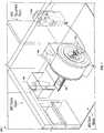
- FIG. 1is an illustration of an exemplary layout of an MRI Control Room, an MRI Scan Room, and an MRI Equipment Room;
- FIG. 2is an illustration of a perspective view of a patient inserted into an MRI, with a head fixation and stabilization system installed;
- FIG. 3illustrates a probe driver
- FIGS. 4A and 4Bare flow charts illustrating an exemplary procedure for treating a patient
- FIGS. 5A through 5Eillustrate a low profile skull anchoring device and exemplary guide stems
- FIGS. 5F and 5Gillustrate a guide stem and sheath configured to interconnect with the low profile skull anchoring device
- FIGS. 5H and 5Iillustrate example internal configurations of a guide sheath
- FIG. 6is a flow chart illustrating an example method for determining trajectory adjustments based upon initial position and orientation of probe introduction equipment upon the skull of a patient;
- FIGS. 7A through 7Cillustrate a high intensity focused ultrasound probe
- FIGS. 8A and 8Billustrate a method for MR thermal monitoring using offset thermal imaging planes
- FIG. 9illustrates exemplary hardware of a workstation.
- the words “a,” “an” and the likegenerally carry a meaning of “one or more,” unless stated otherwise.
- the term “plurality”, as used herein,is defined as two or more than two.
- the term “another”, as used herein,is defined as at least a second or more.
- the terms “including” and/or “having”, as used herein,are defined as comprising (i.e., open language).
- the term “program” or “computer program” or similar terms, as used herein,is defined as a sequence of instructions designed for execution on a computer system.
- a “program”, or “computer program”,may include a subroutine, a program module, a script, a function, a procedure, an object method, an object implementation, in an executable application, an applet, a servlet, a source code, an object code, a shared library/dynamic load library and/or other sequence of instructions designed for execution on a computer system.
- the system or methodmay include one or more processors and circuits that embody aspects of various functions by executing corresponding code, instructions and/or software stored on tangible memories or other storage products.
- a displaymay include various flat-panel displays, including liquid crystal displays.
- hyperthermiaThe treatment of tumors by heat is referred to as hyperthermia or thermal therapy. Above approximately 57° C., heat energy needs only to be applied for a short period of time since living tissue is almost immediately and irreparably damaged and killed, for example through a process called coagulation, necrosis, or ablation. Malignant tumors, because of their high vascularization and altered DNA, are more susceptible to heat-induced damage than healthy tissue.
- heat energyis applied to produce reversible cell damage.
- Temporary damage to cellular structuresmay cause the cells to be more conducive to certain therapies including, in some examples, radiation therapy and chemotherapy.
- the treatmentmay cause hemostasis, reduction or dissolution of thrombi or emboli, alteration of functional membranes including the blood-brain barrier, and/or renal filtration.
- the physical-biological effectsmay be caused directly by temperature change to the cells, tissues, and/or body fluids or indirectly (e.g., downstream) from the temperature change, such as alterations in heat shock proteins or immune reaction or status.
- Different types of energy sourcesfor example, laser, microwave, radiofrequency, electric, and ultrasound sources may be selected for heat treatment based on factors including: the type of tissue that is being treated, the region of the body in which the tissue to be treated is located, whether cellular death or reversible cellular damage is desired, the nature of energy application parameters for each source, and variability of the energy application parameters.
- the energy sourcemay be extracorporeal (i.e., outside the body), extrastitial (i.e., outside the tumor), or interstitial (i.e., inside the tumor).
- ITTinterstitial thermal therapy
- a tumoris heated and destroyed from within the tumor itself, energy may be applied directly to the tumor instead of requiring an indirect route through surrounding healthy tissue.
- energy depositioncan be extended throughout the entire tumor. The energy can be applied to heat tissue in the treatment area to a temperature within a range of about 45° to 60° C.
- An exemplary ITT processbegins by inserting an ultrasound applicator including one or more transducers into the tumor.
- the ultrasonic energy from the applicatormay therefore extend into the tissue surrounding the end or tip including the one or more transducers to effect heating within the tumor.
- the transducer(s)is/are aligned with an edge of the applicator and the applicator is rotatable so as to rotate the ultrasonic energy beam around the axis of the applicator to effect heating of different parts of the tumor at positions around the applicator.
- the transducer(s)are presented on a tip of the applicator or otherwise surrounding an inserted portion of the applicator.
- the applicatormay be moved longitudinally and/or rotated to effect heating of the tumor over a full volume of the targeted region.
- the ultrasonic applicatoris controlled and manipulated by a surgeon with little or no guidance apart from the surgeon's memory of the anatomy of the patient and the location of the tumor.
- imagesmay be used during the ITT process to provide guidance for treatment.
- locations of tumors and other lesions to be excisedcan be determined using a magnetic resonance imaging (MRI) system or computer tomography (CT) imaging system.
- MRI imagingcan be used in real time to control or aid in guidance accuracy in an automated or semi-automated fashion.
- thermographye.g., MR thermography, ultrasonic thermography, etc.
- the temperature informationcan be used to monitor necrosis of tumor tissue while ensuring that surrounding (healthy) tissue suffers minimal to no damage.
- the temperature feedbackin some implementations, is used to perform either or both of: automating engagement of the ultrasonic energy and cooling functionality of the ultrasonic applicator. In this manner, it is possible to control a temperature distribution or thermal dose in and around the tumor.
- a system in accordance with this disclosureincorporates magnetic resonance imaging (MRI) compatible energy emission probes and/or other treatment devices and accessories for effective and controlled delivery of thermal therapy to a wide range of locations and tumor sizes within a brain.
- MRImagnetic resonance imaging
- the systemis not limited to MRI-guided thermal therapy, as other therapies such as computer tomography (CT) can also be utilized.
- CTcomputer tomography
- this disclosurerefers to an MRI scanner as an example medical imaging machine, which may be referred to simply as an MRI.
- the interface platform 102is secured to a patient table 108 of an MRI system 110 .
- the MRI system 110may include a head coil and stabilization system (herein stabilization system), an instrument adaptor, and an MRI trajectory wand.
- Exemplary MRI systemsthat can be utilized together with the features discussed herein include those manufactured by Siemens A G, Kunststoff, Germany (including the MAGNETOM AVANTO, TRIO, ESPREE, VERIO MRI Systems, which are trademarks and/or trade names of Siemens A G).
- example MRI systemsinclude those manufactured by General Electric Company, Fairfield, Conn. (including the SIGNA, OPTIMA and DISCOVERY MRI systems, which are trademarks and/or trade names of General Electric Company).
- all of the above components of the interface platform 102 and the energy emission therapy equipmentare MRI compatible, which refers to a capability or limited capability of a component to be used in an MRI environment.
- an MRI compatible componentoperates and does not significantly interfere with the accuracy of temperature feedback provided by the MRI system operating with exemplary flux densities including: magnetic flux densities of 1.5 T or 3.0 T, where no hazards are known for a specified environment (e.g., 1.5 T or 3.0 T).
- Compatibilitycan also be defined with respect to one or more other magnetic flux densities, including at least 0.5 T, 0.75 T, 1.0 T, 2 T, and 5 T.
- the system electronics rack 104includes cables, penetration panels and hardware that effectuates mechanical, electrical, and electronic operation of the energy emission therapy equipment and the MRI system 110 .
- the system electronics rack 104may further be used to power and route control signals and/or communications for the control workstation 106 .
- the workstation 106includes a display that displays a user interface, e.g., a graphical user interface (GUI) and/or a command line interface that enables a user to plan a treatment procedure and interactively monitor the procedure, the interface platform 102 , and the entire MRI system 110 .
- GUIgraphical user interface
- the user interfacealso provides the user, e.g., a medical professional, the ability to directly control the energy emission therapy equipment including an energy source associated therewith, and therefore, enables directly control of the application of the therapy to the patient.
- FIG. 2an exemplary position of a patient on the patient table 108 of the MRI system 110 is illustrated.
- the interface platform 102is secured to the patient table 108 together with a head coil 202 and stabilization system, which is a head fixation device that immobilizes a patient's head.
- the stabilization systemincludes a head fixation ring 204 .
- a probe 206 and probe driver 208are coupled to probe introduction equipment 210 , and to the interface platform 102 via umbilicals.
- a cablefor example, can be used to provide data, laser, fluid, etc. connections between the probe 206 , probe driver 208 , and interface platform 102 and the electronics rack 104 in the MRI equipment room (as illustrated in FIG. 1 ).
- the probe introduction equipment 210includes at least a portion that is detectable by the MRI system (e.g., included in temperature data that is displayed by an imaging portion of the MRI system) and is used for trajectory determination, alignment, and guidance of the probe 206 .
- An MRI trajectory wande.g., an MRI detectable, fluid-filled tube
- the probe 206may be introduced into the probe introduction equipment 210 to effect surgery or therapy.
- the probe 206may be composed of MRI compatible materials that permit concurrent energy emission and thermal imaging, and can be provided in multiple lengths, cross-sectional areas, and dimensions.
- Types of probes that can be utilized with the components and procedures discussed hereininclude RF, HIFU, microwave, cryogenic, and chemical release probes; the chemical release probes may include photodynamic therapy (PDT), and drug releasing probes.
- Treatments in accordance with the descriptions provided in this disclosureinclude treatments that ablate (i.e., “treat”) a tissue to destroy, inhibit, and/or stop one or more or all biological functions of the tissue, or otherwise cause cell damage or cell death that is indicated by a structural change in cells of the targeted tissue area.
- Ablationcan be effected by laser, RF, HIFU, microwave, cryogenic, PDT and drug or chemical release.
- a corresponding probe and/or other instrumentsuch as a needle, fiber or intravenous line can be utilized to deliver one or more of these ablation agents intracorporeally or percutaneously and proximate to, in the vicinity of, abutting, or adjacent to a targeted tissue area so as to effect treatment.
- the probe 206can be a gas-cooled probe so as to control delivery of the energy to the targeted tissue area. The length and diameter of the probe 206 is preselectable based on the targeted tissue area and/or the ROI.
- the probe 206in some particular examples, can be a laser delivery probe that is used to deliver laser interstitial thermal therapy or a HIFU applicator that is used to deliver HIFU interstitial thermal therapy.
- the probe driver 208controls positioning, stabilization and manipulation of the probe 206 within a specified degree of precision or granularity.
- the components of the probe driver 208generally include a commander 302 , umbilicals 304 , a follower 306 , and a position feedback plug 308 that receives position feedback signals from, for example, potentiometers within the follower 306 .
- the probe 206(illustrated in FIG. 2 ) can be inserted into the follower 306 , and the follower 306 can control a rotational and longitudinal alignment and/or movement of the probe 206 .
- the probe driver 208can further include a rotary test tool (not illustrated) that can be used during a self-test procedure to simulate attaching a probe to the follower 306 .
- a rotary test tool(not illustrated) that can be used during a self-test procedure to simulate attaching a probe to the follower 306 .
- An exemplary probe driverthat can be utilized in accordance with the various aspects presented in this disclosure is described in U.S. Pat. No. 8,728,092 to Qureshi, entitled “Stereotactic Drive System” and filed Aug. 13, 2009, the entirety of which is incorporated herein by reference.
- the probe driver 208(illustrated in FIG. 2 ) is mounted to the interface platform 102 .
- the position feedback plug 308(illustrated in FIG. 3 ) connects to the interface platform 102 in order to communicate the position of the probe 206 to the user and/or the workstation 106 (illustrated in FIG. 1 ).
- the probe driver 208is used to rotate or translate, e.g., by extending or retracting the probe 206 .
- the probe driver 208in a particular example, can provide, at a minimum, a translation of 20-80 mm, 30-70 mm, 40-60 mm or 40 mm, with a maximum translation of 60 mm, 80 mm, 100 mm, 120 mm or 60-150 mm.
- the probe driver 208further to the example, can also provide, at a minimum, a rotation of 300°-340°, with a maximum rotation of 350°, 359°, 360°, 540°, 720° or angles therebetween.
- the workstation 106outputs signals to the MRI system 110 to initiate certain imaging tasks.
- the workstation 106outputs signals to an intermediary system or device that causes the MRI system 110 to initiate the imaging tasks.
- the workstation 106additionally outputs signals to the electronics rack 104 .
- the electronics rack 104includes various actuators and controllers that control the thermal therapy devices, such as, in some examples, a cooling fluid pressure and/or a flow rate of the cooling fluid, and a power source that powers a thermal therapy device.
- the power sourceis a laser source that outputs laser light via an optical fiber. As illustrated in FIG.
- the electronics rack 104is located in an MRI Equipment Room and includes storage tanks to hold the cooling fluid, one or more interfaces that receive the signals from the control workstation 106 and/or a separate MRI workstation, an energy emission source (e.g. laser), and an output interface.
- One or more of the interfacesare connected with or include physical wiring or cabling that receives the signals and transmits other signals, as well as physical wiring or cabling that transmit energy to corresponding components in the MRI Scan Room through a portal that routes the signals and/or energy in a manner that minimizes any interface with or by the MRI system 110 .
- the wiring or cablingare connected at or by the interface platform 102 to corresponding components to effect and actuate control of a thermal therapy device and/or an associated thermal therapy session.
- the systemis indicated for use to ablate, necrotize, carbonize, and/or coagulate the targeted tissue area (e.g., an area of soft tissue) through interstitial irradiation or thermal therapy, in accordance with neurosurgical principles, with a HIFU thermal therapy device.
- the HIFU thermal therapy device or probeincludes ultrasonic transducers for directing ultrasonic energy at the targeted tissue area, causing the tissue to heat.
- the ultrasonic beam of the HIFU probecan be geometrically focused (e.g., using a curved ultrasonic transducer or lens) or electronically focused (e.g., through adjustment of relative phases of the individual elements within an array of ultrasonic transducers).
- the focused beamcan be directed at particular locations, allowing treatment of multiple locations of an ROI without mechanical manipulation of the probe.
- the depth of treatmentcan be controlled by adjusting the power and/or frequency of the one or more transducers of the HIFU probe.
- a laser-based thermal therapyis utilized in the MRI system.
- Laser probes of a variety of outputscan be utilized, including, in some examples, laser probes emitting laser light having wavelengths of 0.1 nm to 1 mm, and laser probes emitting laser light in one or more of the ultraviolet, visible, near-infrared, mid-infrared, and far-infrared spectrums.
- Types of lasers used with respect the laser probeinclude, for example, gas lasers, chemical lasers, dye lasers, metal-vapor lasers, solid-state lasers, semiconductor lasers, and free electron lasers.
- one or more wavelengths of the laser light emitted by the laser probeare within the visible spectrum, and one or more wavelengths of the laser probe are within the near-infrared spectrum.
- the environment 100can be utilized for planning and monitoring thermal therapies effected via MRI-imaging, and can provide MRI-based trajectory planning for the stereotactic placement of an MRI compatible (conditional) probe.
- the environment 100provides real-time thermographic analysis of selected MRI images and thus, temperature feedback information and/or thermal dose profiles for the targeted tissue area.
- thermographic analysis of the MRI imagescan provide real-time verification of cellular damage in a targeted tissue area that corresponds to necrosis, carbonization, ablation, and/or coagulation.
- thermographic analysiscan be used to monitor tissue surrounding a periphery of an ROI to ensure minimal if any damage to healthy tissues.
- Components of the environment 100may assist in guiding, planning, adjusting, performing and confirming a thermal therapy session and trajectories associated therewith.
- a procedureincludes, generally, identifying an ROI and/or associated targeted tissue areas in a patient that should be treated, planning one or more trajectories for treating the tissue, preparing the patient and components for the treatment, and performing the treatment. Aspects of the various parts of the treatment are described throughout this disclosure, and an exemplary sequence of treatment steps is illustrated in FIGS. 4A and 4B .
- FIG. 4Aa process flow diagram illustrates an exemplary method 400 for pre-planning a treatment of a patient.
- pre-treatment Digital Imaging and Communications in Medicine (DICOM) image datais loaded and co-registered, for example, via the workstation 106 (illustrated in FIG. 1 ).
- DICOMDigital Imaging and Communications in Medicine
- one or more ROIs and/or targeted tissue areas and one or more initial trajectoriescan be determined and set ( 402 ).
- a head coil and fixation systemis attached to the patient ( 404 ), for example by positioning the head coil and stabilization system on the surgical table.
- the patientcan be immobilized using a head fixation ring.
- the patient's headcan be secured with the head fixation ring and remain fixed for the entire imaging portion of the flow chart in FIG. 4A .
- An example head fixation systemis described in U.S. Provisional Application Ser. No. 61/955,124 entitled “Image-Guided Therapy of a Tissue” and filed Mar. 18, 2014.
- a probe entry location into the skullPrior to applying thermal energy to an ROI, a probe entry location into the skull is identified.
- a burr holeis drilled in the skull ( 406 ).
- the burr holemay be drilled prior to attachment of probe introduction equipment (e.g., a miniframe, anchoring device, guide stem, instrument sheath, etc.).
- probe introduction equipmente.g., a miniframe, anchoring device, guide stem, instrument sheath, etc.
- a twist-drill holein certain embodiments, can be created following a trajectory alignment of the probe introduction equipment.
- the twist-drill holecan have a size of 1-5 mm, 2 mm, 3 mm, 4 mm or 4.5 mm.
- the probe introduction equipmentsuch as a stereotactic miniframe or low profile anchoring device, in certain embodiments, is attached to the patient's head ( 408 ).
- Probe aligning equipmentsuch as the miniframe or guide stem, can then be aligned along the intended trajectory, for example using image-guided navigation.
- the head coilcan be attached.
- An exemplary head coil systemis described in U.S. Provisional Application Ser. No. 61/955,124 entitled “Image-Guided Therapy of a Tissue” and filed Mar. 18, 2014.
- the interface platformmay be attached prior to or after MRI trajectory confirmation.
- the order of steps in a site-specific processmay be determined based on members of MRI or surgical support team and may be determined during on-site training with respect to the MRI system.
- the interface platformIP is attached to the head end of the head coil and stabilization system. Then, the IP power and motor plugs are connected.
- the patientis positioned in a MRI cabin, and MRI imaging is performed to confirm a trajectory ( 410 ) associated with a thermal therapy device and/or probe introduction equipment.
- a trajectory410
- an MRI trajectory wandmay be inserted into the probe introduction equipment for use in confirming its trajectory.
- the trajectory of the probe introduction equipmentfor example, can be evaluated using MRI imaging prior to inserting a probe into the brain.
- Volumetric imaging or volumetric visualizationmay be captured to include the entire head and full extent of the probe introduction equipment, independently of ablation.
- beam fiducial marker detectionmay also be performed.
- the captured imagesmay also display a position of a beam fiducial marker located in a portion of the probe introduction equipment. This marker can be detected and identified by the MRI imaging system and method to store an orientation of the physical direction of the probe.
- the captured imagesin implementations where pre-treatment image data is not available, can be used for planning a thermal therapy session.
- a probe actuation and guidance devicee.g., a follower
- a test toolare attached to the probe introduction equipment, to provide positional feedback for a self-test function ( 412 ).
- the self-test functionmay be used to confirm that inputs to the probe actuation and guidance device, (e.g., from the workstation), accurately and/or precisely drive the probe.
- the rotary test toolmay be removed.
- the procedure equipmentmay be introduced and the procedure initiated.
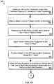
- a process flow diagramillustrates an exemplary method 420 for a treatment procedure.
- a probeis attached and inserted into the probe introduction equipment and/or the patient's skull (e.g., secured for manipulation via the probe actuation and guidance device) ( 422 ).
- Exemplary implementations of neurosurgical probesare discussed in below under the section entitled “Probes.” It is noted that different types of probes can be used in conjunction different types of thermal therapy, for example, when an ROI is not in the brain.
- An MRI scancan then be conducted to ensure probe alignment is correct and confirm movement and delivery of the probe along the intended trajectory.
- the acquired image datacan be displayed, along with pre-planning image data by the workstation 106 .
- GUIgraphical user interface
- a usercan adjust the probe displayed by the GUI by interacting with, for example, the GUI to match the probe artifact on the acquired image to ensure that the alignment and arrangement of the probe as physically placed in the probe introduction equipment and inserted into the patient coincides with the rendered probe at the workstation.
- the probe's trajectoryfor example, can be adjusted to a desired position for delivering thermal energy, via interaction with the GUI. Further, the probe's rotational position can also be adjusted to a desired direction or angle for thermal delivery, via interaction with the GUI.
- one or more scan planesare selected for cuing a thermal monitoring sequence via the MRI system's sequence protocol list ( 424 ).
- a 3D volumeis selected and in yet another embodiment, a linear contour is selected.
- Parameters associated with scan planein some examples, can be entered by a user via a workstation connected with the MRI system or directly into the thermal monitoring sequences protocol's geometry parameters of the MRI.
- temperature feedback information and/or thermal dose profilesare initialized and monitored ( 426 ).
- at least three reference pointse.g., six, twelve, twenty, etc.
- the ROImay include an overlaid, orange noise mask in one or more image monitoring view panes to illustrate the intended thermal delivery area.
- the noise maskingmay be used to improve accuracy of temperature monitoring during tissue treatment.
- energy delivery via the probeis actuated to begin the thermal therapy session ( 428 ).
- the usermay depress a foot pedal operatively connected to the workstation to deliver thermal energy to the ROI or a targeted tissue area within the ROI.
- Thermal energycan then be either continuously or intermittently delivered while monitoring thermal dose profiles, which can be presented as contours that are overlaid onto one or more (e.g., three) thermal monitoring view panes rendered by the GUI of the work station.
- Thermal deliverymay be halted as desired or as necessary by releasing the foot pedal.
- the view panesmay display an energy dose profile or thermal dose profile supplied by the probe, with respect to a specified time period and/or a specified targeted tissue area or ROI; the thermal dose or energy dose profile can be displayed as a succession of temperature gradients.
- the thermal dose profiles and/or the temperature gradientspermit the determination of an extent of cellular damage in the targeted tissue area and/or other effects upon the targeted tissue area occurring as a result of the thermal therapy.
- a rotational and/or linear alignment of the probemay be adjusted ( 432 ) by translating or rotating the probe. For example, an energy output of the probe may be terminated and then the probe may be subjected to linear translation and/or rotational movement, which can be controlled, for example, by a probe driver (a particular implementation of which is illustrated in FIG. 3 ). After adjusting the probe alignment, in certain embodiments, the process returns to step 422 to verify a current placement of the probe.
- a second thermal treatment procedureis not initiated (e.g., when repeating step 428 ) until one or more targeted tissue areas within the ROI returns to a baseline body temperature.
- the thermal dose associated with the one or more targeted tissue areas in the ROImay continue at various probe rotational and/or linear alignments until the entire ROI has been treated.
- the procedurecan be repeated by attaching the new probe to the probe introduction equipment and verifying probe placement ( 422 ). If, instead, the second probe was initially included within the probe introduction equipment (e.g., via a separate lumen in a guide sheath in relation to the first probe), the user may initiate positioning of the second probe, for example, via the GUI, and verify placement of the second probe ( 422 ).
- a multi-probe configurationis described in greater detail in relation to FIG. 5I .
- step 424involving selection of scan planes for the cuing the thermal monitoring sequence may be skipped. If, instead, a second probe is deployed at a different linear position or a different trajectory, step 422 may be performed to confirm the trajectory and alignment of the second probe.
- the patientis removed from the MRI bore and the probe, probe actuation and guidance device, and probe introduction equipment are detached from the patient.
- the bore holemay be closed, for example, at this time.
- a patient 502when preparing for an intracranial neurosurgical procedure, a patient 502 is fitted with a low profile skull anchoring device 504 , as illustrated in an exemplary mounting illustration 500 of FIG. 5A .
- the low profile skull anchoring device 504may be releasably attached to the head of the patient 502 , for example, using three or more bone anchors mounted to the skull of the patient 502 .
- the low profile skull anchoring device 504includes three bone screws 508 for connecting to bone anchors within the skull of the patient 502 , as well as pins 510 for further securing the low profile skull anchoring device 504 to the head of the patient 502 and for ensuring that the low profile skull anchoring device 504 mounts above the surface of the head of the patient 502 . In this way, there will be minimal or no compression of the patient's scalp.
- the low profile skull anchoring device 504has an oval or an oblong shape.
- the screws 508 and pins 510are composed of, for example, titanium. It should be noted that the screws 508 and the pins 510 are not necessarily limited to three pins; the number of screws 508 and pins 510 used is the number which is necessary to provide sufficient rigidity.
- the screws 508 and pins 510may be evenly spaced around the circumference of the low profile skull anchoring device 504 (e.g., positioned approximately every 120 degrees). In another embodiment, the screws 508 and pins 510 are positioned at unequal distances apart, for example, based on an irregular skull curvature. In yet another embodiment, the screws 508 and the pins 510 are movable with respect to the low profile skull anchoring device 504 . In still another embodiment, the screws 508 are replaced with a sufficiently rigid adhesive or a staple, each of which provide sufficient rigidity to allow for the drilling of a burr hole in the skull.
- the medical teamis provided with greater access for lateral trajectories of biopsy, probes, and other apparatus to be inserted intracranially into the patient 502 via the low profile skull anchoring device 504 .
- Thismay be especially useful when working within the confines of an MRI bore, for example during MRI-guided thermal therapy treatments.
- the low profile skull anchoring device 504may be composed of MRI compatible materials and, optionally, include MRI visible markers for aligning a desired trajectory or defining a particular direction relative to the low profile skull anchoring device 504 .
- the low profile skull anchoring device 504may allow easier access to back-of-the-head entry trajectories, such as trajectories used in performing epilepsy treatments.
- a mounting height of the low profile skull anchoring device 504may be thirty millimeters or less from the surface of the skull of the patient 502 .
- the low profile skull anchoring device 504includes a removable guide stem 506 .
- the removable guide stem 506may lock to the low profile skull anchoring device 504 using a screw mechanism, keyed locking mechanism, or other connector configured to firmly connect the removable guide stem 502 to the low profile skull anchoring device 504 with relative ease of removal.
- the exemplary the low profile skull anchoring device 504includes three connection points 512 for securing the removable guide stem 506 to the low profile skull anchoring device 504 .
- the removable guide stem 506may include a series of guide stem connectors 514 (e.g., screws or locking pins) which mate with the connection points 512 of the low profile skull anchoring device 504 , as shown in FIGS. 5A and 5C .
- the alignment of the guide stem connectors 514 and the connection points 512differs based on a skull curvature of the patient.
- the removable guide stem 506may lock to the low profile skull anchoring device 504 using a keyed mechanism, such as an insert-and-twist slot and tab configuration (not illustrated).
- the removable guide stem 506may releasably connect to the low profile skull anchoring device 504 using retractable locking pins which mate to corresponding depressions.
- retractable pins built into the low profile skull anchoring device 504may be extended to mate with corresponding depressions within the removable guide stem 506 .
- spring-loaded retractable locking pinsmay be pressure-inserted into mating depressions within the removable guide stem 506 , for example by pushing the removable guide stem 506 into the interior diameter of the low profile skull anchoring device 502 .
- a latch or button mechanismmay be used to retract the locking pins and release the removable guide stem 506 from the low profile skull anchoring device 502 .
- Other locking mechanismsare possible.
- a central cylindrical portion of the removable guide stem 506is configured to receive various adapters and/or instruments such as, in some examples, drill bits, biopsy needles, and treatment probes.
- the central cylindrical portion of the removable guide stem 506in certain embodiments, is rotatably adjustable, allowing an orientation of central cylindrical portion of the removable guide stem 506 to be manipulated to align the probe in accordance with a desired trajectory.
- a locking mechanism 516may be actuated to lock the central cylindrical portion of removable guide stem 506 into place at the set alignment.
- the removable guide stem 506may include, for example, a ball joint 518 for establishing an adjustable trajectory for passing instruments to the skull of the patient 502 via the central cylindrical portion of removable guide stem 506 .
- the central portionhas another geometric or polygonal shape that corresponds to a cross-section of the probe.
- interior portions of the central cylindrical portion of the removable guide stem 506are deformable so as to cover an outer surface of the probe.
- the interior portions of the central cylindrical guide stemare comprised of shape memory alloys that have a transition temperature that exceeds a maximum temperature associated with a specified thermal therapy.
- the ball joint 518can achieve a number of trajectories that is based on the granularity with which the ball joint 518 is manipulated.
- the ball joint 518may be clamped into position using the locking mechanism 516 .
- the locking mechanism 516is a cam lock.
- the locking mechanism 516is a ring clamp.
- the locking mechanism 516has a screw engagement.
- the ball joint 518upon positioning of the trajectory, may be clamped into position using a ring clamp (not illustrated).
- the ball jointmay be perforated and/or indented at set increments such that, rather than an infinitely adjustable trajectory, the removable guide stem 506 has a multiple selection trajectory allowing for precise adjustment.
- a screw engagement or locking pinmay lock the ball joint 518 at the selected position.
- guide lines or trajectory markersmay indicate a selected trajectory (e.g., in relation to a plane of the low profile skull anchoring device 504 ).
- FIGS. 5D and 5Eillustrative examples of a removable guide stem 520 including both a tilt adjustment 522 and a rotation adjustment 524 are shown.
- the separate tilt adjustment 522 and rotation adjustment 524may be used to more precisely adjust a trajectory of the central cylindrical portion of removable guide stem 520 .
- a tilt lock mechanism 526such as a screw and hole or locking pin and pin slot, may be activated to hold the central cylindrical portion of removable guide stem 520 at the selected tilt position.
- a rotation lock mechanism 528such as a screw and hole or locking pin and pin slot, may be activated to hold the removable guide stem 520 at the selected rotation.
- the tilt adjustment 522 and/or rotation adjustment 524includes a graduated friction lock, such that asserting pressure along the line of adjustment causes the trajectory to “click” to a next incremental setting (e.g., one, two, or five degrees). In this circumstance, a user can count a number of clicks to determine a present relative trajectory selected.
- the graduated friction lockincludes a rack and pinion mechanism. In another embodiment, the graduated friction lock includes detents and a spring-loaded plunger.
- guide linessuch as a set of guide lines 530 are marked on the removable guide stem 520 (or the removable guide stem 506 illustrated in FIG. 5A ) to provide a user with an indication of the selected trajectory.
- an angle of tilt in relation to the low profile skull anchor 504may be selected via the guide lines 530 (e.g., within a one, two, or five degree angle of adjustment).
- the guide lines 530are MR indicators, such that an MR image captured of the removable guide stem 520 will allow a software package to register an initial trajectory in relation to the head of the patient (e.g., patient 502 of FIG. 5A ).
- either the first removable guide stem 506 or the second removable guide stem 520may be modified to include an x,y degree of freedom adjustment mechanism (not illustrated). In this manner, a position of the central cylindrical portion of guide stem 506 in relation to a burr hole opening beneath the low profile skull anchor 504 may be adjusted by the user. Rather than the central cylindrical portion of guide stem 506 or 520 being centered within the low profile skull anchor 504 , for example, an x,y adjustment mechanism may allow an offset of the central cylindrical portion of removable guide stem 506 or 520 .
- the central cylindrical portion of guide stem 506 or 520may be adjusted by up to at least ten to twenty millimeters to be centered above the burr hole using an x,y adjustment mechanism.
- the x,y adjustment mechanismmay be configured using an adjustable spring loaded cam and locking mechanism (e.g., set pin or screw).
- the x,y adjustment mechanismmay be configured using an adjustable hinge configuration, such that the legs of the “Y” shape of the guide stem 506 are capable of swinging along an adjustment travel of the hinge configuration.
- the guide stem 506may be adjustably connected to the low profile skull anchor 504 .
- the guide stem 506may connect to an adjustable gantry system, such that the x,y displacement of the guide stem 506 can be set through an adjustable gantry.
- the x, y adjustment mechanismcan be configured using a rotatable ring configured between the low profile skull anchor 504 and the guide stem 506 , such that the Y shape of the guide stem 506 may be twisted to a desired trajectory and then the guide stem 506 may be adjusted closer to the low profile skull anchor 504 along an adjustment leg of the Y shape.
- an adjustment mechanismmay be provided along a particular leg of the Y shape such that, to implement x,y adjustment, the Y is first rotated into a desired position, and then linear travel effected along the adjustment branch of the Y.
- the removable guide stem mechanismincludes an X-shaped connection to aid in x,y adjustment.
- the x,y adjustment mechanismcan include a slideable gantry with locking mechanisms such as a clamp or set screw.
- the x,y adjustmentmay include a screw drive, allowing a user to twist and adjust the displacement of the central position of the guide stem 506 in either or both the x direction and the y direction.
- the spring-loaded cam and/or hinge system adjustment mechanisms described above in relation to the Y-shaped configurationare equally applicable to an X-shaped configuration.
- the skull entry locationbecomes accessible, for example to allow for formation of a burr hole or to otherwise prepare the skull entry location.
- the removable guide stem 506 or 520may be locked to the low profile skull anchor 504 .
- the removable guide stem 520may be locked to the low profile skull anchor device 504 by attaching screws at three connection locations 532 .
- the removable guide stem 520may be clamped to the low profile skull anchor device 504 .
- the guide stem 520may be removed. Removal of the guide stem 520 , for example, allows a medical professional quick access to react to bleeding or to adjust the burr hole opening for trajectory correction.
- the low profile skull anchoring device 504may first be aligned with screw anchors mounted upon the patient's skull and then screwed to the head of the patient 502 , as illustrated in FIG. 5A .
- the skull entry locationmay be prepared for treatment during the thermal therapy while the removable guide stem 506 or 520 has been separated from the low profile skull anchoring device 504 .
- the removable guide stem 506 or 520may be replaced and its trajectory aligned.
- the removable guide stem 506 , 520is automatically manipulated.
- the removable guide stem manipulationmay be performed by software executing upon the commander 302 of the probe driver 208 as described in relation to FIG. 3 .
- the removable guide stem 506may be manipulated via a trajectory planning module of a software system, such as software executing upon the workstation 106 of FIG. 1 .
- the manipulations of the removable guide stem 506 , 520may be performed by a probe actuation and guidance device. In a particular example, as described in relation to the method 400 of FIG.
- a test toolmay be inserted into the removable guide stem 506 , 520 , and the test tool may be aligned with pre-treatment image data to determine an initial trajectory.
- automatic manipulationmay be supplemented with real time images supplied by an image guided system (e.g., MRI-imaging system).
- the test tool alignmentmay be monitored and verified by a software algorithm through capture of MRI images during manipulation.
- an operatormanually adjusts the trajectory of the removable guide stem 506 , 520 .
- Alignment of the trajectory of the removable guide stem 506 , 520is aided by one or more guide lines or fiducial markers upon the surface of the low profile skull anchoring device 504 and/or upon the surface of the removable guide stem 506 , 520 , such as the guide lines 530 illustrated in FIG. 5D .
- the trajectoryis locked via a locking mechanism, such as the locking mechanism 516 of FIG. 5C or the locking mechanisms 526 and 528 of FIG. 5D .
- instrumentsmay be guided into the skull via the removable guide stem 506 or 520 .
- biopsy tools, a thermal treatment probe, medicament delivery probe, or other neurosurgical devicemay be delivered to a ROI of the brain of the patient via the removable guide stem 506 or 520 .
- FIG. 6is a flow chart illustrating an example method 600 for determining trajectory adjustments based upon initial position and orientation of probe introduction equipment upon the skull of a patient.
- the method 600may be used in determining a trajectory prior to conducting a neurosurgical procedure.
- the method 600is performed by software executing upon the workstation 106 , as described in relation to FIG. 1 .
- the method 600is performed by software executing upon the commander 302 of the probe driver 208 as described in relation to FIG. 3 .
- the method 600begins with obtaining an MRI image of a skull of a patient fitted with probe introduction equipment ( 602 ).
- the MRI imagefor example, may be obtained by the MRI system 110 , as described in relation to FIG. 1 .
- MRI image data including two or more imagesmay be obtained from a remote medical system, for example through a hospital file transfer system. Further, MRI image data, in some implementations, may be scanned into the system and loaded into the software.
- one or more fiducial markers identifying probe introduction equipmentare determined from the MRI image ( 604 ).
- a software system installed upon the workstation 106can review the MRI image data for graphical data matching a known fiducial marker related to probe introduction equipment.
- a particular shape or series of shapesmay be indicative of the location of probe introduction equipment, such as the low profile skull anchoring device 504 described in relation to FIGS. 5A through 5E or the stereotactic miniframe described in U.S. patent application Ser. No. 13/838,310 to Tyc, entitled Image-Guided Therapy of a Tissue and filed Mar. 15, 2013, which is hereby incorporated by reference in its entirety.
- a type of the probe introduction equipmentmay be determined based upon one or more of the shapes, sizes, lengths, and/or positions of the identified fiducial marker(s) ( 608 ). For example, based upon a particular arrangement or shape of fiducial marker, the software algorithm may differentiate the low profile skull anchoring device from the stereotactic miniframe. In another example, a particular arrangement of fiducial markers may be used to differentiate a low profile skull anchoring device with an x,y adjustment guide stem from a low profile skull anchoring device with an immobile guide stem.
- the type of probe introduction equipmentmay be known ( 606 ).
- the softwaremay be bundled with particular probe introduction equipment such that the fiducial markers are only used to identify positioning of the known probe introduction equipment.
- a usermay manually enter the type of probe introduction equipment into the software (e.g., through a drop-down selection menu or other selection mechanism).
- a communicationmay be received from the probe introduction equipment by the software, identifying the type or model of probe introduction equipment.
- an algorithm executing upon the commander 302 of the probe driver 208(illustrated in FIG. 3 ) communicates information regarding the type of probe introduction equipment to the software.
- a position and orientation of the probe introduction equipmentis determined using the identified fiducial markers ( 610 ). For example, based upon a particular distribution of fiducial markers, the software may identify the mounting location of the probe introduction equipment in relation to the skull of the patient. Fiducial markers, as a particular illustration, may identify the relative locations of the bone screws 508 of the low profile skull anchoring device 504 , as illustrated in FIG. 5B . In another example, the trajectory of the guide stem 506 , as illustrated in 5 C, may be determined based upon an angle of a fiducial marker line or shape upon the guide stem 506 .
- the position and orientation of the probe introduction equipmentis determined with reference to the skull of the patient. For example, identifying relative locations of the bone screws 508 based upon fiducial markers upon the low profile skull anchor 504 may identify position of the head of the patient. In another example, fiducial marker stickers may be applied to the head of the patient to identify the head relative to the probe introduction equipment. Features of the head of the patient, such as brow, ears, nose, or cheek bones, for example, may be highlighted to orient the position of the low profile introduction equipment in relation to the face of the patient.
- position and orientation of the probe introduction equipmentis determined relative to imaging or head stabilization equipment.
- the position and orientation of the probe introduction equipmentmay be determined based upon one or more fiducial marker reference points on the head coil 202 or the head fixation ring 204 , as illustrated in FIG. 2 .
- a position of a portion of the probe introduction equipmentmay be identified in relation to other probe introduction equipment.
- an x,y degree of freedom adjustment mechanismmay have been used to modify the position of the central cylindrical portion of guide stem in relation to a burr hole opening beneath the probe introduction equipment. If the central cylindrical portion of the guide stem is offset in relation to the low profile skull anchoring device 504 , for example, the software may calculate the position of the offset.
- a representation of the probe introduction equipmentis overlaid on the displayed MRI image ( 612 ).
- the softwaremay overlay a reference image (e.g., semi-transparent image, dotted outline, etc.) representing the location of at least a portion of the probe introduction equipment.
- a position and orientation of the guide stem 506 attached to the low profile anchoring device 504(e.g., as illustrated in FIGS. 5A and 5C ) may be presented to the user.
- the overlaid imagein some embodiments, mimics the look and design of the actual probe introduction equipment. In other embodiments, the overlaid image is a simple dotted line orientation image that may bear little similarity to the look of the actual equipment.
- a target region of interest in the skull of the patientis determined ( 614 ).
- pre-treatment image datamay be used to identify one or more treatment regions of interest.
- a usermay manually identify a region of interest, for example by highlighting or circling the region of interest within the MRI image.
- the region of interestmay include a tumor or portion of a tumor.
- the region of interestis identified as a three-dimensional location within the skull of the patient.
- the region of interestmay identify a target point for a tip of a probe to reach.
- the region of interestmay identify a three-dimensional volume.
- the region of interestmay describe a tumor or a portion of a tumor to be treated.
- a trajectoryis determined for reaching the target region of interest ( 616 ).
- the softwaremay identify an access path leading from the probe introduction equipment (as identified by via the fiducial markers) to the region of interest.
- the access pathin some implementations, depends upon features of the brain discerned to be within a general path leading from the probe introduction equipment to the target region of interest.
- the features avoided by the softwaremay include the brain stem, particularly fibrous tissues or major arteries.
- the softwareanalyzes MRI images of the patient to identify known delicate and/or difficult to traverse features.
- a usermay highlight within scanned images of the patient's brain one or more features to avoid when selecting a trajectory.
- the softwareidentifies two or more potential access paths and selects between the access paths. For example, depending upon particularly delicate or difficult to maneuver features of the brain between the region of interest and the position of the probe introduction equipment, the software may select between two or more possible access paths to identify the path least likely to cause difficulties during the procedure.
- the two or more possible access pathsinclude a path to one end of a target volume versus a path to another end of a target volume.
- the two or more possible access pathsinclude two or more curved access paths to a single target point. The curved access path, for example, may be determined based upon identification of therapeutic instruments that will be used during the procedure.
- a usermay identify a particular probe or other equipment capable of curved trajectory towards a region of interest.
- a pre-shaped probefor example, may be designed to deploy from the probe introduction equipment 210 (e.g., a guide sheath or guide stem) at a particular angle of curvature.
- the softwarefor example, upon receiving identification of the probe being used, may access data regarding the angle of curvature of the selected probe.
- the software algorithmmay recommend a deployment device (e.g., guide sheath, guide sleeve, etc.) including an offset distal opening at a particular angle to effect the desired curved trajectory of a flexible cannula or laser fiber.
- the off-axis delivery hole 558may be used to deploy the flexible cannula or laser fiber at a particular angle.
- a flexible cannula or laser fibercan be automatically directed along a trajectory.
- a flexible cannula or laser fibermay be capable of curved guidance using magnetic steering.
- one or more gradient coilsmay be used to guide the flexible cannula or laser fiber along a curved path to access a region of interest.
- the softwaremay access capabilities of the magnetic steering system and flexible cannula or fiber to determine potential trajectory paths. Determining the trajectory, further to this example, may include determining commands to provide to a magnetic steering system to guide the flexible cannula or laser fiber to the region of interest.
- a robotic steering devicesuch as a robotic worm may be used to pull a flexible neurosurgical instrument towards the region of interest along the curved access path.
- the robotic wormmay be remotely controlled to navigate a path towards a difficult to access region of interest while pulling or otherwise feeding the flexible neurosurgical device into position.
- the robotic wormmay be programmed to follow a predetermined path to the region of interest such that, upon deployment (e.g., via a guide sheath or rigid cannula), the robotic worm steers the flexible neurosurgical instrument into position at the region of interest.
- the robotic wormin some implementations, is further designed to create a path, for example through fibrous tissue, by cutting or bluntly pushing aside tissue to provide access for the flexible neurosurgical instrument.
- determining the trajectoryincludes determining commands to provide to the robotic worm to guide the flexible neurosurgical instrument to the region of interest.
- one or more recommended adjustments for setting a trajectory of the probe introduction equipmentare determined based upon the location of the region of interest and the initial position and orientation of the probe introduction equipment ( 618 ).
- the softwareidentifies one or more adjustment features and/or ranges of motion of the particular type of probe introduction equipment. For example, using the guide stem 506 described in relation to FIG. 5C , the software may identify that the guide stem 506 has an infinitely adjustable trajectory via the ball joint, and based upon present orientation, to achieve the desired trajectory, a user may wish to align the guide stem 506 with particular guide lines.
- the software algorithmmay identify two separate adjustments for setting the desired trajectory, both the tilt adjustment and the rotation adjustment (e.g., as identified by guide lines or other adjustment markers (or “clicks”) of the tilt adjustment 522 and/or the rotation adjustment 524 ).
- the softwaremay identify adjustment ranges of the x-y degree of freedom adjustment mechanism and recommend a modified offset of the guide stem to align with an optimal trajectory for reaching the region of interest.
- the one or more recommended adjustmentsare provided for review by a medical professional ( 620 ).
- the adjustmentsmay be presented upon a display in communication with the workstation 106 .
- the adjustmentsmay be presented upon the display region of the interface platform 102 (as illustrated in FIG. 2 ) such that a user may review the instructions while setting the trajectory of the probe introduction equipment.
- a displaced positioning of the representation of the probe introduction equipmentmay be overlaid on the displayed MRI image (e.g., illustrating the recommended alignment of the adjusted probe introduction equipment with the region of interest).
- the medical professionalmay manually adjust the probe introduction equipment to the new trajectory.
- the probe driver 208illustrated in FIG. 3
- the softwaremay issue commands to the probe driver 208 to adjust a trajectory of the guide stem after receiving confirmation from a user that the guide stem locking mechanism is in an unlocked position. Upon positioning, the software may prompt the user to engage the locking mechanism, locking the guide stem into position.
- the usermay request confirmation of desired trajectory via the software.
- the softwaremay compare present fiducial marker alignment with anticipated fiducial marker alignment (e.g., based upon change in position of the fiducial markers).
- the softwaremay re-calculate a trajectory using the present fiducial markers and verify that the new trajectory aligns with the region of interest.
- the softwarein a third example, may calculate an anticipated trajectory based upon the identified alignment (e.g., based upon a present position of the fiducial markers) and compare the anticipated trajectory to the trajectory calculated in step 616 . Should the adjustment be misaligned for some reason, at least steps 616 and 618 of the method 600 may repeated as necessary.
- a guide sheath 540is inserted into the removable guide stem (e.g., removable guide stem 506 ),.
- the guide sheath 540may include, for example, one or more distal openings and one or more proximal openings to introduce at least one neurosurgical instrument to the ROI in the patient's brain.
- a hollow trocarmay be introduced via the removable guide stem 506 or 520 to prepare an initial entry into a region of the brain.
- a trocar or stylettemay be used to cut a path for the neurosurgical instrument.
- the stylette or trocarmay have a sharp distal opening to cut a path through the fibrous area.
- the trocar or stylettemay have a bullet shaped nose to bluntly push tissue out of the trajectory path.
- a stylette or trocarmay be introduced to the region of interest via the guide sheath 540 .
- the guide sheath 540locks to the removable guide stem 506 .
- the guide sheath 540may be configured to lock to the removable guide stem 506 at a variable linear height depending upon a distance between the skull opening and a ROI.
- the guide sheath 540may be deployed in proximity to, in the vicinity of, or adjacent to an ROI without abutting or entering the ROI.
- a “wiper” mechanism designed into the distal end of the guide sheath 540may aid in avoiding contaminants within the guide sheath 540 .
- a guide stem locking mechanism 519may be used to clamp the guide sheath 540 at a particular linear depth.
- the guide sheath 540may have spaced indentations or other connection points for interfacing with the guide stem locking mechanism 519 (e.g., set screw or spring-loaded plunger).
- the guide sheathmay have spaced ratcheting teeth for interfacing with a ball plunger or toggle release.
- the indentations(or, alternatively, ratcheting teeth) may be positioned at precise measurements (e.g., 1 mm apart) to aid in linear position adjustment.
- the guide sheath 540 and guide stem locking mechanism 519may be configured to provide positive feedback to a medical professional during adjustment.
- a linear actuator systemsuch as a rack and pinion may be used to provide precise linear position adjustment (e.g., one “click” per millimeter).
- a cam lock mechanismmay be used to engage teeth or depressions within the guide sheath 540 .
- a cam lock mechanismsuch as the locking mechanism 516 illustrated in FIG. 5C may be used to lock the guide sheath 540 at a selected linear depth.
- the removable guide stem 520similarly includes a guide stem locking mechanism 534 .
- the guide sheath 540may directly connect to the low profile skull anchoring device 504 or to another receiving port connected to the low profile skull anchoring device 504 (not illustrated).
- the guide sheath 540upon interlocking with the guide stem 506 , 520 and/or the low profile skull anchoring device 504 and receiving one or more neurosurgical tools, may create an air-tight seal during a neurosurgical operation.
- the proximal and/or distal end of the guide sheath 540may include a receiving port adaptable to the surgical instrument being introduced.
- the proximal and/or distal end of the guide sheath 540may include an adjustable aperture that may be dialed or electronically set to a particular diameter matching a present neurosurgical instrument.
- various guide sheathscan be used interchangeably with the guide stem 506 , 520 , such that a guide sheath corresponding to the surgical instrument diameter may be selected.
- one or more guide sleevesmay be secured inside the guide sheath 540 , each of the one or more guide sleeves having a different distal end diameter.
- a divided (e.g., bifurcated) guide sleevein certain embodiments, may be used to introduce two or more instruments simultaneously or concurrently, each with a particular instrument diameter.
- the guide sheath 540is intracranially delivered using an introducer and guide wire.
- An image guidance systemsuch as the MRI imaging system, may be used instead of or in addition to the introducer and guide wire during placement of the guide sheath 540 .
- the guide sheath 540may be composed of MRI compatible materials.
- the materials of the guide sheath 540are selected to provide rigid or inflexible support during introduction of one or more neurosurgical tools within the guide sheath 540 .
- the guide sheath 540may be composed of one or more of Kevlar, carbon fiber, ceramic, polymer-based materials, or other MRI-compatible materials.
- the geometry of the guide sheath 540in certain embodiments, further enhances the strength and rigidity of the guide sheath 540 .
- the guide sheath 540(or guide sleeve, as described above) includes two or more lumens for introduction of various neurosurgical instruments.
- a series of treatmentsmay be performed without interruption of the meninges layer between treatments.
- FIG. 5Iillustrates two neurosurgical instruments 552 and 554 that are simultaneously inserted into a guide sheath 550 and can be used to carry out treatment of a tissue consecutively, concurrently, or simultaneously.
- Neurosurgical instruments deployed via the guide sheath 540may exit a same distal opening or different distal openings.
- the guide sheath 540may include at least one off-axis distal opening.
- exemplary guide sheath 550includes a contact surface 556 having a predefined angle. Upon encountering the contact surface 556 , the trajectory of a surgical instrument 552 presented through the guide sheath 550 may be deflected to exit the proximal end via an off-axis delivery hole 558 , as illustrated in FIG. 5I .
- the angles shown in FIGS. 5H and 5Ican be considered as drawn to scale in one implementation.
- the alignment of the contact surface 556 and the delivery hole 558can be varied by adjusting their respective axial angles. By adjusting these angles, a number of possible positions of the surgical instrument 554 are provided. Further, multiple off-axis delivery holes and multiple contact surfaces can be provided, which are displaced from each other in a direction of the longitudinal axis of the guide sheath.
- the guide sheath 540Upon introducing a neurosurgical instrument such as a probe, in certain embodiments, the guide sheath 540 enables coupling between the probe and a probe actuation and guidance device. For example, commands for linear and/or rotational control of the probe may be issued to the probe via an interface within the guide sheath 540 .
- Example probesare described in: U.S. Pat. No. 8,256,430 to Torchia, entitled “Hyperthermia Treatment and Probe Therefor” and filed Dec. 17, 2007; U.S. Pat. No. 7,691,100 to Torchia, entitled “Hyperthermia Treatment and Probe Therefor” and filed Aug. 25, 2006; U.S. Pat. No. 7,344,529 to Torchia, entitled “Hyperthermia Treatment and Probe Therefor” and filed Nov. 5, 2003; U.S. Pat. No. 7,167,741 to Torchia, entitled “Hyperthermia Treatment and Probe Therefor” and filed Dec.
- a number of probe lengthsare provided in any of the probe examples described herein based on a degree of longitudinal travel allowed by a follower and a depth of the tissue to be treated.
- An appropriate probe lengthcan be determined by the interface platform and/or the workstation during a planning stage, or determined during a trajectory planning stage.
- Exemplary probe lengthscan be indicated on the probes with reference to a probe shaft color, in which white can indicate “extra short” having a ruler reading of 113 mm, yellow can indicate “short” having a ruler reading of 134 mm, green can indicate “medium” having a ruler reading of 155 mm, blue can indicate “long” having a ruler reading of 176 mm, and dark gray can indicate “extra long” having a ruler reading of 197 mm.
- Different model numberingscan also be utilized on the probes to indicate different lengths.
- a therapeutic window of wavelengths for thermal therapy using a laser proberanges from 800 to 1100 nm. Wavelengths lower than 800 (e.g., within the visible spectrum) lack the energy to effectively heat tissue, while wavelengths above 1100 nm rapidly heat an immediate region, thereby being useful in applications such as tattoo removal where a thin region is burned.
- a laser probehas a 1064 nm wavelength for coagulation of tissue. The 1064 nm wavelength, for example, is selected based upon water absorption properties of laser wavelengths. By minimizing water absorption, for example, depth of penetration can be maximized.
- the 1064 nm laser probefor example, may be used to apply thermal therapy to a three-dimensional zone approximately two to four centimeters in diameter.
- the 1064 nm wavelengthallows deeper penetration and provides a higher power density associated with energy application so as to more efficiently effect thermal therapy.
- the laser probeis cooled via Joule-Thompson cooling, which eliminates and/or minimizes energy absorption and scatter, as discussed in further detail below.
- the laser probeis a side-firing laser probe to focus the energy of the 1064 nm wavelength laser.
- the photon scatteringcan cause difficulties in focusing the therapy. Depth of penetration may be improved through focusing a laser beam using a side-firing design. Similar benefits may be achieved in designing a side-firing HIFU probe, as described below.
- An energy output pattern of a probesuch as a laser probe or HIFU probe, in certain embodiments, includes a pulsed output pattern.
- a higher power densitymay be achieved without causing tissue scorching by pulsing a high power laser treatment for x seconds with y seconds break between (e.g., allowing for tissue in the immediate vicinity to cool down).
- pulsingallows the system to vary energy delivered to a region of interest without affecting the power density applied to the region of interest. In this manner, higher energy can be applied to a region of interest without causing damage (e.g., scorching) to immediate tissue.
- the energy output pattern of a probemay include a ten Watt output for 2 to 2.5 seconds followed by a one to 1.5 second period of inactivity (e.g., delivering approximately 398 Joules per minute).
- a particular energy output patternmay be developed based upon the type of probe (e.g., laser, HIFU, etc.), an emission style of the probe tip (e.g., side-firing, diffuse tip, etc.), and/or the depth of the ROI and/or the targeted tissue area (e.g., based in part on the shape of a tumor region, etc.).
- the energy output pattern for the diffuse tip probemay include a ten Watt output for 2 seconds, followed by a 0.3 second period of inactivity (e.g., delivering approximately 500 Joules per minute).
- the energy output patternmay be adjusted. For example, the period of inactivity may be lengthened or shortened depending upon a temperature gradient between the tissue closest to the probe and the depth of treatment (e.g., the furthest tissue being thermally ablated).
- the power output of the probemay be adjusted instead of or in addition to the period of inactivity, based upon thermal imaging feedback. For example, to increase a treatment radius, the power density supplied by the probe may be increased.
- the laser probemay include a cooling tip to cool tissue within the immediate vicinity.
- the tip of the laser probemay cool to approximately 0 to 5 degrees Celsius.
- a cryogenic cooling devicee.g., cooling tube
- a thermocouple within the cooling devicecan be read during inactive periods to avoid interference caused by energy emission.
- the 1064 nm wavelengthallows deeper penetration and higher power density; that is, thermal therapy can cause cellular damage to a targeted tissue region in a shorter period of time.
- a treatment patternincludes effecting treatment while concurrently or simultaneously moving the probe (e.g., linearly and/or rotationally).
- a HIFU probemay be automatically rotated (e.g., using a commander and follower as described in FIG. 3 , etc.) while an emission pattern is simultaneously or concurrently adjusted to effect treatment to a desired depth based upon a particular geometry of the ROI.
- the power density of the HIFU probemay be tuned for the first treatment depth.
- a second radial portion of the tumormay have a depth of 2 centimeters, and the power density of the HIFU probe may be increased accordingly to tune for the treatment depth of 2 centimeters. If two or more ultrasonic transducers are included in the HIFU probe, the power may be varied on a per-transducer basis or to the entire transducer array.
- HIFU technologyadvantageously provides directional control and greater depth penetration as compared with laser-based thermal therapy.
- ultrasonic therapymay achieve at least three to four times greater depth penetration.
- estimated depths of thermal treatment using HIFU technologyinclude three to five centimeters or greater than six centimeters.
- treatmentmay be provided at a greater depth, it also may be provided using a narrow focal beam, containing a width of the treated tissue.
- HIFU-based thermal therapycan advantageously achieve a greater penetration depth than laser-based thermal therapy, the ultrasonic treatment has greater uniformity over temperature gradients than laser-based thermal therapy, which heats a portion of the targeted tissue area close to the probe much more rapidly than portions of the targeted tissue area further away from the probe.
- scorching or carbonization of the targeted tissue area close to the probemay be avoided and/or the HIFU probe may be operated independently of external cooling to protect immediately surrounding tissue.
- constructive and destructive interferencecan be utilized by selecting a number of different longitudinal spaced emission points to fine tune a position and depth of energy applied to a targeted tissue area and/or an ROI.
- the depth of energymay be tuned to conform with a non-uniform, irregular, and/or non-polygonal shape of the ROI which, for example, corresponds to a tumor.
- power supplied to the transducers of a side firing HIFU probemay be varied as the HIFU probe is rotated to a new position, thereby adjusting penetration of the ultrasonic energy to a depth of the a region of interest (e.g., tumor) at the present angle of rotation.
- HIFU treatmentmay be used to “sculpt” an irregularly shaped three-dimensional lesion conforming to a region of interest through power variance during rotation of the probe.
- HIFU treatmentmay reach a penetration depth of three to five centimeters or even greater than six centimeters, it is imaginable that an irregularly-shaped tumor of at least 5 centimeters in diameter may be treated without the need to adjust an initial trajectory of the HIFU probe.
- the side-fire HIFU probemay treat an ROI having a tumor volume of up to 110 cubic centimeters. In other embodiments, the side-fire HIFU probe may treat an ROI having a tumor volume with a range of approximately 0.1 cubic centimeters and 110 cubic centimeters.
- Preparing trajectories, determining linear translational adjustments and/or rotational movements, and/or energy output patternsmay be selected and/or optimized to prevent heating of the skull and/or bouncing energy off of the surfaces of the skull.
- HIFU treatmentin some examples, can be used for opening a blood-brain barrier, coagulation of tissue, or cavitation of tissue.
- the HIFU probe 702includes one or more side-firing transducers 704 for effecting treatment to the ROI 706 .
- the ultrasonic transducer(s) 704may be flat or rounded.
- the HIFU probein some examples, can include a shaft composed of plastic, brass, titanium, ceramic, polymer-based materials, or other MRI-compatible materials in which one or more ultrasonic transducer(s) 704 have been mounted.
- the ultrasonic transducer(s) 704may be mounted upon an interior surface of the shaft of the HIFU probe 702 .
- the ultrasonic transducer(s) 704may include a linear array of individually controllable transducers, such that a frequency or power output of each transducer 704 may be individually tuned to control a treatment beam of the HIFU probe 702 .
- the tip of the probe 702can include a linear array of three transducers 704 .
- the longitudinally spaced apart transducers 704can be spaced equally apart. However, in other implementations, the spacing between the transducers 704 can be unequal.
- the HIFU probe 702includes a cooling mechanism for cooling the ultrasonic transducers 704 .
- a cooling fluid or gasmay be delivered to the tip of the HIFU probe 702 to control a temperature of the ultrasonic transducer(s) 704 .
- the ultrasonic transducer(s) 704may be surrounded by an acoustic medium, such as an acoustic coupling fluid (e.g., water) to enable ultrasonic frequency tuning of the ultrasonic transducer(s) 704 .
- an acoustic coupling fluide.g., water
- the HIFU probe 702is embedded within an ROI 706 spanning multiple MR thermal monitoring planes 708 .
- thermal effects within each MR thermal monitoring plane 708may be monitored in order to monitor thermal coagulation of the ROI 706 .
- Information derived from the thermal monitoringmay be fed back into control algorithms of the HIFU probe 702 , for example, to adjust a power intensity and/or frequency of the HIFU probe to tune a depth of treatment of the ultrasonic beam or to adjust a rotational and/or linear positioning of the HIFU probe 702 upon determining that ablation is achieved at a current rotational and linear position.
- additional MR thermal monitoring planes 708may be monitored (e.g., between four and eight planes, up to twelve planes, etc.).
- the three thermal monitoring planes 708may be spread out over the y-axis such that a first gap exists between plane 708 a and plane 708 b and a second gap exists between plane 708 b and plane 708 c .
- the thermal monitoring algorithmin this circumstance, can interpolate data between the MR thermal monitoring planes 708 .
- At least three thermal monitoring planeseach at a distinct imaging angle bisecting an axis defined by a neurosurgical instrument such as a thermal ablation probe, may be interpolated to obtain thermal data regarding a three-dimensional region.
- an aspect illustration 800demonstrates three MR thermal monitoring planes 802 for monitoring ablation of an ROI 804 by a probe 806 .
- the angles between the thermal monitoring planesmay be based upon an anatomy of the region of the skull of the patient or a shape of the ROI.
- the angles, in some examples,may differ by at least ten degrees.
- an end view 810 of the probe 806provides an illustrative example of MR thermal monitoring planes 802 that are each offset by sixty degrees.
- the thermal monitoring planes 802provide a more realistic three-dimensional space. Temperature gradients and/or thermal dose profiles between the thermal monitoring planes 802 can be interpolated. Similar to increasing a number of parallel MR thermal monitoring planes, in other implementations, four or more thermal monitoring planes may be captured and combined, for example, to increase thermal monitoring accuracy.
- the HIFU probe 702As a result of the side-firing capability of the HIFU probe 702 , a number of rotationally different portions of the ROI can be treated with the ultrasonic energy by rotating the HIFU probe 702 .
- the HIFU probe 702may be rotated is illustrated in an arrow 712 to effect treatment throughout the ROI 706 .
- the HIFU probe 702can be longitudinally translated, for example automatically by a follower of a probe driver, to change a longitudinal position at which ultrasonic energy is applied within the ROI 706 .
- Rotation, power intensity, duty cycle, longitudinal positioning, and coolingare controlled by the electronics rack 104 and the workstation 106 , such as the electronics rack 104 and workstation 106 described in relation to FIG. 1 .
- a sequencesuch as an algorithm or software encoding, can be executed to cause a probe tip or a number of probe tips to execute a particular energy output pattern effect a predefined thermal therapy to a targeted tissue area.
- the energy output patterncan be based on rotational and/or longitudinal movements of the probe.
- the procedures and routines described hereincan be embodied as a system, method or computer program product, and can be executed via one or more dedicated circuits or programmed processors. Accordingly, the descriptions provided herein may take the form of exclusively hardware, exclusively software executed on hardware (including firmware, resident software, micro-code, etc.), or through a combination of dedicated hardware components and general processors that are configured by specific algorithms and process codes. Hardware components are referred to as a “circuit,” “module,” “unit,” “device,” or “system.” Executable code that is executed by hardware is embodied on a tangible memory device, such as a computer program product. Examples include CDs, DVDs, flash drives, hard disk units, ROMs, RAMs and other memory devices.
- FIG. 9illustrates an example processing system 900 , and illustrates example hardware found in a controller or computing system (such as a personal computer, i.e., a laptop or desktop computer, which can embody a workstation according to this disclosure) for implementing and/or executing the processes, algorithms and/or methods described in this disclosure.
- the processing system 900 in accordance with this disclosurecan be implemented in one or more the components shown in FIG. 1 .
- One or more processing systemscan be provided to collectively and/or cooperatively implement the processes and algorithms discussed herein.
- the processing system 900 in accordance with this disclosurecan be implemented using a microprocessor 902 or its equivalent, such as a central processing unit (CPU) and/or at least one application specific processor ASP (not shown).
- the microprocessor 902is a circuit that utilizes a computer readable storage medium 904 , such as a memory circuit (e.g., ROM, EPROM, EEPROM, flash memory, static memory, DRAM, SDRAM, and their equivalents), configured to control the microprocessor 902 to perform and/or control the processes and systems of this disclosure.
- a controllersuch as a disk controller 906 , which can controls a hard disk drive or optical disk drive.
- the microprocessor 902 or aspects thereof, in alternate implementations,can include or exclusively include a logic device for augmenting or fully implementing this disclosure.
- a logic deviceincludes, but is not limited to, an application-specific integrated circuit (ASIC), a field programmable gate array (FPGA), a generic-array of logic (GAL), and their equivalents.
- ASICapplication-specific integrated circuit
- FPGAfield programmable gate array
- GALgeneric-array of logic
- the microprocessor 902can be a separate device or a single processing mechanism. Further, this disclosure can benefit from parallel processing capabilities of a multi-cored CPU.
- results of processing in accordance with this disclosurecan be displayed via a display controller 908 to a display device (e.g., monitor) 910 .
- the display controller 908preferably includes at least one graphic processing unit, which can be provided by a number of graphics processing cores, for improved computational efficiency.
- an I/O (input/output) interface 912is provided for inputting signals and/or data from microphones, speakers, cameras, a mouse, a keyboard, a touch-based display or pad interface, etc., which can be connected to the I/O interface as a peripheral 914 .
- a keyboard or a pointing devicefor controlling parameters of the various processes and algorithms of this disclosure can be connected to the I/O interface 912 to provide additional functionality and configuration options, or control display characteristics.
- An audio processor 922may be used to process signals obtained from I/O devices such as a microphone, or to generate signals to I/O devices such as a speaker.
- the display device 910can be provided with a touch-sensitive interface for providing a command/instruction interface.
- the above-noted componentscan be coupled to a network 916 , such as the Internet or a local intranet, via a network interface 918 for the transmission or reception of data, including controllable parameters.
- a central BUS 920is provided to connect the above hardware components together and provides at least one path for digital communication there between.
- the workstation shown in FIG. 1can be implemented using one or more processing systems in accordance with that shown in FIG. 9 .
- the workstationcan provide control signals to peripheral devices attached to the I/O interface 912 , such as actuators 924 to drive probe positioning and actuation equipment.
- the workstationin some implementations, can communicate with additional computing systems, such as an imaging unit 926 and/or an MRI unit 928 , via the I/O interface 912 .
- One or more processorscan be utilized to implement any functions and/or algorithms described herein, unless explicitly stated otherwise.
- the equipment rack and the interface platformeach include hardware similar to that shown in FIG. 9 , with appropriate changes to control specific hardware thereof.
- These computer program instructionsmay also be stored in a computer-readable medium that can direct a computer or other programmable data processing apparatus to function in a particular manner, such that the instructions stored in the computer-readable medium produce an article of manufacture including instruction means which implement the function/act specified in the flowchart and/or block diagram block or blocks.
- the computer program instructionsmay also be loaded onto a computer or other programmable data processing apparatus to cause a series of operational steps to be performed on the computer or other programmable apparatus to produce a computer implemented process such that the instructions which execute on the computer or other programmable apparatus provide processes for implementing the functions/acts specified in the flowchart and/or block diagram block or blocks.
Landscapes
- Health & Medical Sciences (AREA)
- Life Sciences & Earth Sciences (AREA)
- Surgery (AREA)
- Engineering & Computer Science (AREA)
- Biomedical Technology (AREA)
- Nuclear Medicine, Radiotherapy & Molecular Imaging (AREA)
- Public Health (AREA)
- General Health & Medical Sciences (AREA)
- Veterinary Medicine (AREA)
- Animal Behavior & Ethology (AREA)
- Heart & Thoracic Surgery (AREA)
- Medical Informatics (AREA)
- Molecular Biology (AREA)
- Physics & Mathematics (AREA)
- Pathology (AREA)
- Otolaryngology (AREA)
- Radiology & Medical Imaging (AREA)
- Robotics (AREA)
- Biophysics (AREA)
- Oral & Maxillofacial Surgery (AREA)
- Electromagnetism (AREA)
- Optics & Photonics (AREA)
- Neurosurgery (AREA)
- High Energy & Nuclear Physics (AREA)
- Plasma & Fusion (AREA)
- Magnetic Resonance Imaging Apparatus (AREA)
- Dentistry (AREA)
- Mechanical Engineering (AREA)
Abstract
Description
Claims (4)
Priority Applications (1)
| Application Number | Priority Date | Filing Date | Title |
|---|---|---|---|
| US15/362,516US10675113B2 (en) | 2014-03-18 | 2016-11-28 | Automated therapy of a three-dimensional tissue region |
Applications Claiming Priority (3)
| Application Number | Priority Date | Filing Date | Title |
|---|---|---|---|
| US201461955121P | 2014-03-18 | 2014-03-18 | |
| US14/661,310US20150265353A1 (en) | 2014-03-18 | 2015-03-18 | Image-guided therapy of a tissue |
| US15/362,516US10675113B2 (en) | 2014-03-18 | 2016-11-28 | Automated therapy of a three-dimensional tissue region |
Related Parent Applications (1)
| Application Number | Title | Priority Date | Filing Date |
|---|---|---|---|
| US14/661,310Continuation-In-PartUS20150265353A1 (en) | 2014-03-18 | 2015-03-18 | Image-guided therapy of a tissue |
Publications (2)
| Publication Number | Publication Date |
|---|---|
| US20170296289A1 US20170296289A1 (en) | 2017-10-19 |
| US10675113B2true US10675113B2 (en) | 2020-06-09 |
Family
ID=60039785
Family Applications (1)
| Application Number | Title | Priority Date | Filing Date |
|---|---|---|---|
| US15/362,516Active2036-04-03US10675113B2 (en) | 2014-03-18 | 2016-11-28 | Automated therapy of a three-dimensional tissue region |
Country Status (1)
| Country | Link |
|---|---|
| US (1) | US10675113B2 (en) |
Cited By (1)
| Publication number | Priority date | Publication date | Assignee | Title |
|---|---|---|---|---|
| US11707637B2 (en)* | 2014-09-02 | 2023-07-25 | Universite de Bordeaux | Focused ultrasound cardiac stimulation system, portable device and cardiac stimulation, and associated methods |
Families Citing this family (12)
| Publication number | Priority date | Publication date | Assignee | Title |
|---|---|---|---|---|
| CA2918879A1 (en) | 2013-07-24 | 2015-01-29 | Centre For Surgical Invention & Innovation | Multi-function mounting interface for an image-guided robotic system and quick release interventional toolset |
| CA3020915A1 (en)* | 2016-04-15 | 2017-10-19 | Stryker European Holdings I, Llc | Cannula lock with a brake that rotates and anchors that deploy into the bone against which the cannula lock is set |
| IL310828A (en) | 2017-03-31 | 2024-04-01 | Empyrean Medical Systems Inc | A three-dimensional beam that creates an x-ray radiation source |
| EP3655103A1 (en) | 2017-07-18 | 2020-05-27 | Sensus Healthcare, Inc. | Real-time x-ray dosimetry in intraoperative radiation therapy |
| US11672491B2 (en) | 2018-03-30 | 2023-06-13 | Empyrean Medical Systems, Inc. | Validation of therapeutic radiation treatment |
| US11839447B2 (en) | 2018-04-23 | 2023-12-12 | Mr Instruments, Inc. | Wearable open and adjustable MRI head coil |
| US10940334B2 (en)* | 2018-10-19 | 2021-03-09 | Sensus Healthcare, Inc. | Systems and methods for real time beam sculpting intra-operative-radiation-therapy treatment planning |
| WO2021007077A1 (en)* | 2019-07-05 | 2021-01-14 | Cianna Medical, Inc. | Systems and methods for localizing markers within a body |
| WO2021108773A1 (en) | 2019-11-26 | 2021-06-03 | Rhieneck Thomas J | Conformable mri receiver coil system capable of supporting ultrasound, diagnostic, therapeutic, and interventional implements |
| EP4087512A4 (en)* | 2020-01-09 | 2024-02-14 | Canon U.S.A. Inc. | IMPROVED PLANNING AND VISUALIZATION WITH A CURVED INSTRUMENT PATH AND CURVED INSTRUMENT |
| WO2022187832A2 (en)* | 2021-03-02 | 2022-09-09 | Gyrus Acmi, Inc. D/B/A Olympus Surgical Technologies America | Tissue therapy energy delivery using optical imaging |
| WO2024233974A1 (en)* | 2023-05-11 | 2024-11-14 | GE Precision Healthcare LLC | Systems and methods for radiation therapy management |
Citations (594)
| Publication number | Priority date | Publication date | Assignee | Title |
|---|---|---|---|---|
| US3021842A (en) | 1958-11-05 | 1962-02-20 | John F Flood | Hypodermic needle guide |
| US3139990A (en) | 1961-12-11 | 1964-07-07 | Central Res Lab Inc | Rugged-duty master-slave manipulator |
| DE2621909A1 (en) | 1976-05-17 | 1977-12-01 | Gobiet Wolfgang | Measurement of intracranial pressure in brain - is by miniature blood pressure sensor mounted in cranium by screw:in jig |
| US4111209A (en) | 1977-04-18 | 1978-09-05 | Datascope Corporation | Topical hypothermia apparatus and method for treating the human body and the like |
| JPS5488120A (en) | 1977-12-26 | 1979-07-13 | Nippon Berubon Seiki Kougiyou | Three legs |
| US4233979A (en) | 1977-05-06 | 1980-11-18 | Siemens Aktiengesellschaft | Method of screwing an adapter into the human cranium |
| US4360028A (en) | 1980-01-14 | 1982-11-23 | Barbier Jean Y | Cranial insertion of surgical needle utilizing computer-assisted tomography |
| US4378016A (en) | 1981-07-15 | 1983-03-29 | Biotek, Inc. | Artificial endocrine gland containing hormone-producing cells |
| US4402694A (en) | 1981-07-16 | 1983-09-06 | Biotek, Inc. | Body cavity access device containing a hormone source |
| JPS5942165A (en) | 1982-09-02 | 1984-03-08 | Nippon Steel Corp | Preheating method of slit nozzle for producing amorphous alloy light-gauge strip |
| JPS60154698A (en) | 1984-01-25 | 1985-08-14 | 株式会社日立製作所 | Soldering method |
| US4568559A (en) | 1984-02-06 | 1986-02-04 | Biotek, Inc. | Composite core coated microparticles and process of preparing same |
| US4609174A (en) | 1984-11-05 | 1986-09-02 | Koma Nakatani | Foldable easel |
| US4623588A (en) | 1984-02-06 | 1986-11-18 | Biotek, Inc. | Controlled release composite core coated microparticles |
| US4622953A (en) | 1983-01-13 | 1986-11-18 | Gordon Robert T | Process for the treatment of atherosclerotic lesions |
| US4646752A (en) | 1983-04-25 | 1987-03-03 | Swann Karl W | Adjustable intracranial pressure measuring screw |
| US4671254A (en) | 1985-03-01 | 1987-06-09 | Memorial Hospital For Cancer And Allied Diseases | Non-surgical method for suppression of tumor growth |
| US4733929A (en) | 1986-02-05 | 1988-03-29 | Brown David C | Diffuser fiber incident energy concentrator and method of using same |
| US4733660A (en) | 1984-08-07 | 1988-03-29 | Medical Laser Research And Development Corporation | Laser system for providing target specific energy deposition and damage |
| US4832024A (en) | 1986-04-29 | 1989-05-23 | Georges Boussignac | Cardio-vascular catheter for shooting a laser beam |
| US4914608A (en) | 1988-08-19 | 1990-04-03 | The United States Of America As Represented By The Department Of Health And Human Services | In-vivo method for determining and imaging temperature of an object/subject from diffusion coefficients obtained by nuclear magnetic resonance |
| WO1990005494A1 (en) | 1988-11-18 | 1990-05-31 | Istituto Neurologico 'carlo Besta' | Process and apparatus particularly for guiding neurosurgical operations |
| US4986628A (en) | 1988-08-23 | 1991-01-22 | Lozhenko Alexandr S | Light guide device for phototherapy |
| US5059415A (en) | 1989-02-21 | 1991-10-22 | The State Of Oregon Acting By And Through The Oregon State Board Of Higher Education On Behalf Of Oregon Health | Method for diagnostically imaging lesions in the brain inside a blood-brain barrier |
| US5078140A (en) | 1986-05-08 | 1992-01-07 | Kwoh Yik S | Imaging device - aided robotic stereotaxis system |
| US5085219A (en) | 1987-10-30 | 1992-02-04 | The Regents Of The University Of California | Adjustable holders for magnetic reasonance imaging rf surface coil |
| US5092891A (en) | 1990-03-08 | 1992-03-03 | Kummer Frederick J | Cement plug for the medullary canal of a bone and coacting tool for installing same |
| US5102410A (en) | 1990-02-26 | 1992-04-07 | Dressel Thomas D | Soft tissue cutting aspiration device and method |
| US5116344A (en) | 1987-04-27 | 1992-05-26 | Elekta Instrument Ab | Apparatus for marking an operating site |
| WO1992010142A1 (en) | 1990-12-10 | 1992-06-25 | Howmedica Inc. | A device and method for interstitial laser energy delivery |
| US5154723A (en) | 1987-12-02 | 1992-10-13 | Olympus Optical Co., Ltd. | Cerebral surgery apparatus |
| US5192278A (en) | 1985-03-22 | 1993-03-09 | Massachusetts Institute Of Technology | Multi-fiber plug for a laser catheter |
| US5196005A (en) | 1991-11-26 | 1993-03-23 | Pdt Systems, Inc. | Continuous gradient cylindrical diffusion tip for optical fibers and method for making |
| US5201742A (en) | 1991-04-16 | 1993-04-13 | Hasson Harrith M | Support jig for a surgical instrument |
| US5207681A (en) | 1987-10-26 | 1993-05-04 | Neurodynamics, Inc. | Drill guide apparatus for perpendicular perforation of the cranium |
| US5207669A (en) | 1989-05-26 | 1993-05-04 | C. R. Bard, Inc. | Optical fiber diffusion tip for uniform illumination |
| CA1317641C (en) | 1985-03-22 | 1993-05-11 | Carter Kittrell | Diagnostic laser probe |
| US5217441A (en) | 1989-08-15 | 1993-06-08 | United States Surgical Corporation | Trocar guide tube positioning device |
| US5222953A (en) | 1991-10-02 | 1993-06-29 | Kambiz Dowlatshahi | Apparatus for interstitial laser therapy having an improved temperature sensor for tissue being treated |
| US5230338A (en) | 1987-11-10 | 1993-07-27 | Allen George S | Interactive image-guided surgical system for displaying images corresponding to the placement of a surgical tool or the like |
| US5242438A (en) | 1991-04-22 | 1993-09-07 | Trimedyne, Inc. | Method and apparatus for treating a body site with laterally directed laser radiation |
| US5246436A (en) | 1991-12-18 | 1993-09-21 | Alcon Surgical, Inc. | Midinfrared laser tissue ablater |
| US5247935A (en) | 1992-03-19 | 1993-09-28 | General Electric Company | Magnetic resonance guided focussed ultrasound surgery |
| WO1993020769A1 (en) | 1992-04-16 | 1993-10-28 | Implemed, Inc. | Cryogenic catheter |
| US5263956A (en) | 1992-03-04 | 1993-11-23 | Neuro Navigational Corporation | Ball joint for neurosurgery |
| US5269777A (en) | 1990-11-01 | 1993-12-14 | Pdt Systems, Inc. | Diffusion tip for optical fibers |
| US5275165A (en) | 1992-11-06 | 1994-01-04 | General Electric Company | Magnetic resonance guided ultrasound therapy system with inclined track to move transducers in a small vertical space |
| US5281213A (en) | 1992-04-16 | 1994-01-25 | Implemed, Inc. | Catheter for ice mapping and ablation |
| US5284144A (en) | 1989-11-22 | 1994-02-08 | The United States Of America As Represented By The Secretary Of The Dept. Of Health & Human Services | Apparatus for hyperthermia treatment of cancer |
| WO1994004220A1 (en) | 1992-08-12 | 1994-03-03 | Vidamed, Inc. | Medical probe device and method |
| US5291890A (en) | 1991-08-29 | 1994-03-08 | General Electric Company | Magnetic resonance surgery using heat waves produced with focussed ultrasound |
| US5292320A (en) | 1992-07-06 | 1994-03-08 | Ceramoptec, Inc. | Radial medical laser delivery device |
| US5307144A (en) | 1991-12-02 | 1994-04-26 | Seikagaku Kogyo Kabushiki Kaisha | Photometer |
| US5307812A (en) | 1993-03-26 | 1994-05-03 | General Electric Company | Heat surgery system monitored by real-time magnetic resonance profiling |
| US5312351A (en) | 1993-01-29 | 1994-05-17 | Gerrone Carmen J | Combined pneumo-needle and trocar apparatus |
| US5320617A (en) | 1993-06-25 | 1994-06-14 | Leach Gary E | Method of laser-assisted prostatectomy and apparatus for carrying out the method |
| EP0610991A2 (en) | 1993-02-08 | 1994-08-17 | Xintec Corporation | Device for laser assisted transurethral resection of the prostate(TURP) |
| US5343543A (en) | 1993-05-27 | 1994-08-30 | Heraeus Surgical, Inc. | Side-firing laser fiber with directional indicator and methods of use in determining the orientation of radiation to be emitted from the side-firing laser fiber |
| US5344419A (en) | 1993-04-23 | 1994-09-06 | Wayne State University | Apparatus and method for making a diffusing tip in a balloon catheter system |
| US5344418A (en) | 1991-12-12 | 1994-09-06 | Shahriar Ghaffari | Optical system for treatment of vascular lesions |
| EP0614651A1 (en) | 1993-03-10 | 1994-09-14 | Kabushiki Kaisha Toshiba | Ultrasonic wave medical treatment apparatus suitable for use under guidance of magnetic resonance imaging |
| US5348048A (en) | 1993-01-08 | 1994-09-20 | Schirado Lowell C | Quick connect coupling system |
| US5354294A (en) | 1993-05-26 | 1994-10-11 | Xintec Corporation | Combination reflectance fiber optic laser beam angle delivery |
| US5354293A (en) | 1989-12-18 | 1994-10-11 | Gesellschaft Fur Strahlen- Und Umweltforschung Mbh | Apparatus for the isotropic irradiation of cavity walls |
| US5366456A (en) | 1993-02-08 | 1994-11-22 | Xintec Corporation | Angle firing fiber optic laser scalpel and method of use |
| US5368032A (en) | 1993-11-09 | 1994-11-29 | General Electric Company | Manually positioned focussed energy system guided by medical imaging |
| US5368031A (en) | 1993-08-29 | 1994-11-29 | General Electric Company | Magnetic resonance surgery using heat waves produced with a laser fiber |
| US5370649A (en) | 1991-08-16 | 1994-12-06 | Myriadlase, Inc. | Laterally reflecting tip for laser transmitting fiber |
| US5374266A (en) | 1991-11-27 | 1994-12-20 | Kabushiki Kaisha Morita Seisakusho | Medical laser treatment device |
| US5387220A (en) | 1993-06-15 | 1995-02-07 | Pisharodi; Maohaven | Stereotactic frame and localization method |
| US5388580A (en) | 1992-08-19 | 1995-02-14 | The United States Of America As Represented By The Department Of Health And Human Services | Head holder for magnetic resonance imaging/spectroscopy system |
| US5409493A (en) | 1990-07-13 | 1995-04-25 | Greenberg; Alex M. | Single-handed surgical drill depth guide |
| US5433717A (en) | 1993-03-23 | 1995-07-18 | The Regents Of The University Of California | Magnetic resonance imaging assisted cryosurgery |
| US5443068A (en) | 1994-09-26 | 1995-08-22 | General Electric Company | Mechanical positioner for magnetic resonance guided ultrasound therapy |
| US5445166A (en) | 1991-06-13 | 1995-08-29 | International Business Machines Corporation | System for advising a surgeon |
| US5454897A (en) | 1994-05-02 | 1995-10-03 | Cincinnati Milacron Inc. | Presser member for fiber laying machine |
| US5454807A (en) | 1993-05-14 | 1995-10-03 | Boston Scientific Corporation | Medical treatment of deeply seated tissue using optical radiation |
| US5454794A (en) | 1993-10-15 | 1995-10-03 | Pdt Systems, Inc. | Steerable light diffusing catheter |
| WO1995029737A1 (en) | 1994-05-03 | 1995-11-09 | Board Of Regents, The University Of Texas System | Apparatus and method for noninvasive doppler ultrasound-guided real-time control of tissue damage in thermal therapy |
| US5469353A (en) | 1993-11-26 | 1995-11-21 | Access Radiology Corp. | Radiological image interpretation apparatus and method |
| JPH07308393A (en) | 1994-03-23 | 1995-11-28 | Yasuo Hashimoto | Cancer treating apparatus |
| US5474564A (en) | 1991-11-01 | 1995-12-12 | Clayman; David A. | Method of utilizing a cerebral instrument guide frame |
| JPH07328028A (en) | 1994-06-15 | 1995-12-19 | Tokai Rika Co Ltd | Marker for cranium fixing device |
| US5476461A (en) | 1994-05-13 | 1995-12-19 | Cynosure, Inc. | Endoscopic light delivery system |
| US5490840A (en) | 1994-09-26 | 1996-02-13 | General Electric Company | Targeted thermal release of drug-polymer conjugates |
| US5492122A (en) | 1994-04-15 | 1996-02-20 | Northrop Grumman Corporation | Magnetic resonance guided hyperthermia |
| US5499313A (en) | 1982-08-06 | 1996-03-12 | Kleinerman; Marcos Y. | Distributed and spatially averaged fiber optic temperature sensors and method using same |
| US5509917A (en) | 1994-06-28 | 1996-04-23 | Ceramoptec Industries, Inc. | Lensed caps for radial medical laser delivery devices |
| US5526814A (en) | 1993-11-09 | 1996-06-18 | General Electric Company | Automatically positioned focussed energy system guided by medical imaging |
| US5530780A (en) | 1993-12-20 | 1996-06-25 | Lederle (Japan), Ltd. | Fiber optic laser conducting and diffusion device |
| US5534000A (en) | 1994-03-17 | 1996-07-09 | Endeavor Surgical Products, Inc. | Laser fiber apparatus having a contact tip and adjacent diffuser element and surgical methods for using same |
| US5537499A (en) | 1994-08-18 | 1996-07-16 | Laser Peripherals, Inc. | Side-firing laser optical fiber probe and method of making same |
| US5553618A (en) | 1993-03-12 | 1996-09-10 | Kabushiki Kaisha Toshiba | Method and apparatus for ultrasound medical treatment |
| US5562688A (en) | 1994-03-25 | 1996-10-08 | Riza; Erol D. | Apparatus facilitating suturing in laparoscopic surgery |
| US5568503A (en) | 1993-10-08 | 1996-10-22 | Terumo Kabushiki Kaisha | Solid-state laser device with optical fiber cable connection |
| US5571099A (en) | 1995-05-09 | 1996-11-05 | Pioneer Optics Company | Side firing probe |
| US5589233A (en) | 1993-12-28 | 1996-12-31 | Applied Materials, Inc. | Single chamber CVD process for thin film transistors |
| EP0755697A2 (en) | 1995-07-28 | 1997-01-29 | Yasuo Hashimoto | Cancer therapeutic instruments |
| US5620479A (en) | 1992-11-13 | 1997-04-15 | The Regents Of The University Of California | Method and apparatus for thermal therapy of tumors |
| US5632767A (en) | 1994-09-09 | 1997-05-27 | Rare Earth Medical, Inc. | Loop diffusers for diffusion of optical radiation |
| US5636259A (en) | 1995-05-18 | 1997-06-03 | Continental X-Ray Corporation | Universal radiographic/fluoroscopic digital room |
| US5638819A (en) | 1995-08-29 | 1997-06-17 | Manwaring; Kim H. | Method and apparatus for guiding an instrument to a target |
| US5643179A (en) | 1993-12-28 | 1997-07-01 | Kabushiki Kaisha Toshiba | Method and apparatus for ultrasonic medical treatment with optimum ultrasonic irradiation control |
| US5647361A (en) | 1992-09-28 | 1997-07-15 | Fonar Corporation | Magnetic resonance imaging method and apparatus for guiding invasive therapy |
| US5663646A (en) | 1995-03-30 | 1997-09-02 | Siemens Aktiengesellschaft | Head antenna for nuclear magnetic resonance examinations |
| US5671353A (en) | 1996-02-16 | 1997-09-23 | Eastman Kodak Company | Method for validating a digital imaging communication standard message |
| US5672171A (en) | 1994-06-30 | 1997-09-30 | American Medical Systems, Inc. | Apparatus and method for interstitial laser treatment |
| US5672172A (en) | 1994-06-23 | 1997-09-30 | Vros Corporation | Surgical instrument with ultrasound pulse generator |
| WO1997040396A1 (en) | 1996-04-25 | 1997-10-30 | The Johns Hopkins University | Method of magnetic resonance imaging and spectroscopic analysis and associated apparatus |
| US5695501A (en) | 1994-09-30 | 1997-12-09 | Ohio Medical Instrument Company, Inc. | Apparatus for neurosurgical stereotactic procedures |
| US5711300A (en) | 1995-08-16 | 1998-01-27 | General Electric Company | Real time in vivo measurement of temperature changes with NMR imaging |
| US5715823A (en) | 1996-02-27 | 1998-02-10 | Atlantis Diagnostics International, L.L.C. | Ultrasonic diagnostic imaging system with universal access to diagnostic information and images |
| US5716369A (en) | 1994-03-25 | 1998-02-10 | Riza; Erol D. | Apparatus facilitating suturing in laparoscopic surgery |
| US5719975A (en) | 1996-09-03 | 1998-02-17 | Hughes Electronics | Optically reconfigurable conductive line element |
| US5728106A (en) | 1993-04-16 | 1998-03-17 | Oregon Neuro-Medical Technology, Inc. | Radio-transparent system for stereotactic radiosurgery and fractionated radiation therapy |
| US5733277A (en) | 1994-06-22 | 1998-03-31 | Pallarito; Allan L. | Optical fibre and laser for removal of arterial or vascular obstructions |
| US5735846A (en) | 1994-06-27 | 1998-04-07 | Ep Technologies, Inc. | Systems and methods for ablating body tissue using predicted maximum tissue temperature |
| US5749549A (en) | 1995-12-29 | 1998-05-12 | Javad Positioning, Llc | Satellite positioning system antenna supporting tripod |
| US5749362A (en) | 1992-05-27 | 1998-05-12 | International Business Machines Corporation | Method of creating an image of an anatomical feature where the feature is within a patient's body |
| US5752962A (en) | 1993-11-15 | 1998-05-19 | D'urso; Paul S. | Surgical procedures |
| WO1998023214A1 (en) | 1996-11-29 | 1998-06-04 | Life Imaging Systems Inc. | System, employing three-dimensional ultrasonographic imaging, for assisting in guiding and placing medical instruments |
| US5762066A (en) | 1992-02-21 | 1998-06-09 | Ths International, Inc. | Multifaceted ultrasound transducer probe system and methods for its use |
| JPH10155805A (en) | 1996-07-29 | 1998-06-16 | Mrc Syst Gmbh | Surgery method by fixed position laser |
| US5769790A (en) | 1996-10-25 | 1998-06-23 | General Electric Company | Focused ultrasound surgery system guided by ultrasound imaging |
| US5772657A (en) | 1995-04-24 | 1998-06-30 | Coherent, Inc. | Side firing fiber optic laser probe |
| US5792110A (en) | 1996-06-26 | 1998-08-11 | Cunningham; Miles G. | Systems and methods for delivering therapeutic agents to selected sites in a subject |
| US5807383A (en) | 1996-05-13 | 1998-09-15 | United States Surgical Corporation | Lasing device |
| JPH10258066A (en) | 1997-03-17 | 1998-09-29 | Suugan Kk | Stand for medical apparatus |
| US5814008A (en) | 1996-07-29 | 1998-09-29 | Light Sciences Limited Partnership | Method and device for applying hyperthermia to enhance drug perfusion and efficacy of subsequent light therapy |
| US5817036A (en) | 1997-02-20 | 1998-10-06 | General Electric Company | System and method for treatment of a prostate with a phase fresnel probe |
| US5823941A (en) | 1995-10-23 | 1998-10-20 | Shaunnessey; Jerome | Apparatus for directing the movement of an endoscopic surgical laser especially for use in vaporizing brain tumors |
| US5824005A (en) | 1995-08-22 | 1998-10-20 | Board Of Regents, The University Of Texas System | Maneuverable electrophysiology catheter for percutaneous or intraoperative ablation of cardiac arrhythmias |
| US5830209A (en) | 1992-02-05 | 1998-11-03 | Angeion Corporation | Multi-fiber laser catheter |
| WO1998051229A1 (en) | 1997-05-15 | 1998-11-19 | Regents Of The University Of Minnesota | Trajectory guides for surgical instruments |
| WO1998052465A1 (en) | 1997-05-23 | 1998-11-26 | Transurgical, Inc. | Mri-guided therapeutic unit and methods |
| US5848967A (en) | 1991-01-28 | 1998-12-15 | Cosman; Eric R. | Optically coupled frameless stereotactic system and method |
| US5855582A (en) | 1995-12-19 | 1999-01-05 | Gildenberg; Philip L. | Noninvasive stereotactic apparatus and method for relating data between medical devices |
| US5855583A (en) | 1996-02-20 | 1999-01-05 | Computer Motion, Inc. | Method and apparatus for performing minimally invasive cardiac procedures |
| US5861020A (en) | 1994-12-09 | 1999-01-19 | Schwarzmaier; Hans-Joachim | Apparatus for irradiating body tissue with laser light |
| US5873845A (en) | 1997-03-17 | 1999-02-23 | General Electric Company | Ultrasound transducer with focused ultrasound refraction plate |
| US5874955A (en) | 1994-02-03 | 1999-02-23 | International Business Machines Corporation | Interactive rule based system with selection feedback that parameterizes rules to constrain choices for multiple operations |
| US5876342A (en) | 1997-06-30 | 1999-03-02 | Siemens Medical Systems, Inc. | System and method for 3-D ultrasound imaging and motion estimation |
| US5891100A (en) | 1995-01-25 | 1999-04-06 | Fleckenstein; Wolfgang | Securing device for brain scan probes |
| US5890897A (en) | 1996-07-22 | 1999-04-06 | Kruger; Bernard M. | Adjustable length drills |
| US5891157A (en) | 1994-09-30 | 1999-04-06 | Ohio Medical Instrument Company, Inc. | Apparatus for surgical stereotactic procedures |
| US5916161A (en) | 1995-09-13 | 1999-06-29 | Kabushiki Kaisha Toshiba | Magnetic resonance imaging apparatus with temperature measurement function |
| US5944663A (en) | 1995-04-28 | 1999-08-31 | Siemens Aktiengesellschaft | Apparatus for treatment with acoustic waves |
| US5945827A (en) | 1996-05-10 | 1999-08-31 | Gore Enterprise Holdings, Inc. | Electromagnetic body coil with vacuum cushions |
| US5947958A (en) | 1995-09-14 | 1999-09-07 | Conceptus, Inc. | Radiation-transmitting sheath and methods for its use |
| US5949929A (en) | 1996-11-25 | 1999-09-07 | Boston Scientific Corporation | Rotatably connecting optical fibers |
| JPH11253562A (en) | 1998-03-12 | 1999-09-21 | Terumo Corp | Laser beam scanning mirror driving device, and laser beam radiation device |
| US5959246A (en) | 1996-06-20 | 1999-09-28 | Arlington Industries, Inc. | Electric box extender and supplemental part |
| US5961466A (en) | 1995-01-03 | 1999-10-05 | Omnicorder Technologies, Inc. | Method of detection of cancerous lesions by their effect on the spatial distribution of modulation of temperature and homogeneity of tissue |
| WO1999051156A1 (en) | 1998-04-02 | 1999-10-14 | Vanderbilt University | Laser surgical cutting probe and system |
| US5978541A (en) | 1996-04-16 | 1999-11-02 | Miravant Systems, Inc. | Custom cylindrical diffusion tips |
| US5989246A (en) | 1992-06-29 | 1999-11-23 | Kaufmann; Raimund | Probe for heating body tissue |
| US6004315A (en) | 1996-09-16 | 1999-12-21 | Focal, Inc. | Optical fiber diffuser and method of making |
| US6006126A (en) | 1991-01-28 | 1999-12-21 | Cosman; Eric R. | System and method for stereotactic registration of image scan data |
| JP2000000319A (en) | 1998-06-12 | 2000-01-07 | Terumo Corp | Energy irradiation device |
| US6019724A (en) | 1995-02-22 | 2000-02-01 | Gronningsaeter; Aage | Method for ultrasound guidance during clinical procedures |
| US6022309A (en) | 1996-04-24 | 2000-02-08 | The Regents Of The University Of California | Opto-acoustic thrombolysis |
| US6039728A (en) | 1992-04-06 | 2000-03-21 | Ceram Optec Gmbh | Working shaft for photo-thermal therapy |
| US6047216A (en) | 1996-04-17 | 2000-04-04 | The United States Of America Represented By The Administrator Of The National Aeronautics And Space Administration | Endothelium preserving microwave treatment for atherosclerosis |
| US6050943A (en) | 1997-10-14 | 2000-04-18 | Guided Therapy Systems, Inc. | Imaging, therapy, and temperature monitoring ultrasonic system |
| US6053912A (en) | 1995-05-01 | 2000-04-25 | Ep Techonologies, Inc. | Systems and methods for sensing sub-surface temperatures in body tissue during ablation with actively cooled electrodes |
| WO2000023000A1 (en) | 1998-10-16 | 2000-04-27 | Regents Of The University Of Minnesota | Mri and magnetic stereotaxis surgical system |
| US6058323A (en) | 1996-11-05 | 2000-05-02 | Lemelson; Jerome | System and method for treating select tissue in a living being |
| JP2000126316A (en) | 1998-08-19 | 2000-05-09 | Tokai Univ | Living tissue heating device using strong light |
| US6067371A (en) | 1995-11-28 | 2000-05-23 | Dornier Medical Systems, Inc. | Method and system for non-invasive temperature mapping of tissue |
| CA2348867A1 (en) | 1998-11-13 | 2000-05-25 | Ergin Atalar | Miniature magnetic resonance catheter coils and related methods |
| WO2000032102A1 (en) | 1998-12-02 | 2000-06-08 | The Board Of Regents, University Of Texas System | Method and apparatus for concomitant structural and biochemical characterization of tissue |
| US6081533A (en) | 1997-06-25 | 2000-06-27 | Com21, Inc. | Method and apparatus for an application interface module in a subscriber terminal unit |
| US6086532A (en) | 1997-09-26 | 2000-07-11 | Ep Technologies, Inc. | Systems for recording use of structures deployed in association with heart tissue |
| US6106516A (en) | 1997-10-30 | 2000-08-22 | Sonique Surgical Systems, Inc. | Laser-assisted liposuction method and apparatus |
| US6117143A (en) | 1998-09-11 | 2000-09-12 | Hybex Surgical Specialties, Inc. | Apparatus for frameless stereotactic surgery |
| US6123719A (en) | 1995-10-24 | 2000-09-26 | Rosslyn Medical Limited | Diagnostic apparatus utilizing radiation interaction with biological tissue |
| US6129670A (en) | 1997-11-24 | 2000-10-10 | Burdette Medical Systems | Real time brachytherapy spatial registration and visualization system |
| US6132437A (en) | 1999-07-14 | 2000-10-17 | Omurtag; Ahmet | Method and stereotactic apparatus for locating intracranial targets guiding surgical instruments |
| US6131480A (en) | 1997-09-03 | 2000-10-17 | Narishige Co., Ltd. | Hydraulically-operated micromanipulator apparatus |
| US6133306A (en) | 1995-01-13 | 2000-10-17 | The General Hospital Corporation | Methods of inhibiting neurodegerative diseases |
| EP1046377A2 (en) | 1999-04-23 | 2000-10-25 | Sherwood Services AG | Microdrive for probes |
| CA2370222A1 (en) | 1999-04-15 | 2000-10-26 | Ergin Atalar | Methods for in vivo magnetic resonance imaging |
| WO2000064003A2 (en) | 1999-04-15 | 2000-10-26 | Surgi-Vision | Magnetic resonance imaging guidewire probe |
| WO2000062672A1 (en) | 1999-04-15 | 2000-10-26 | Surgi-Vision | Methods for in vivo magnetic resonance imaging |
| US6143018A (en) | 1993-05-14 | 2000-11-07 | Ceramoptec Gmbh | Method and device for thermally obliterating biological tissue |
| US6148225A (en) | 1997-09-25 | 2000-11-14 | Siemens Aktiengesellschaft | Ultrasound therapy apparatus and method for operating same during MR monitoring |
| WO2000067640A2 (en) | 1999-05-10 | 2000-11-16 | Brock Rogers Surgical Inc. | Surgical instrument |
| US6151404A (en) | 1995-06-01 | 2000-11-21 | Medical Media Systems | Anatomical visualization system |
| US6152933A (en) | 1997-11-12 | 2000-11-28 | Stereotaxis, Inc. | Intracranial bolt and method of placing and using an intracranial bolt to position a medical device |
| US6159150A (en) | 1998-11-20 | 2000-12-12 | Acuson Corporation | Medical diagnostic ultrasonic imaging system with auxiliary processor |
| US6162052A (en) | 1997-01-31 | 2000-12-19 | J. Morita Manufacturing Corporation | Medical laser handpiece |
| US6164843A (en) | 1998-04-23 | 2000-12-26 | Lino Manfrotto & Co., S.P.A. | Tripod, particularly for photographic uses |
| US6167295A (en) | 1991-01-28 | 2000-12-26 | Radionics, Inc. | Optical and computer graphic stereotactic localizer |
| US6179831B1 (en) | 1999-04-29 | 2001-01-30 | Galil Medical Ltd. | Method of cryoablating benign prostate hyperplasia |
| WO2001006925A1 (en) | 1999-07-26 | 2001-02-01 | The Johns Hopkins University | Method of magnetic resonance imaging and spectroscopic analysis and associated apparatus |
| US6195579B1 (en) | 1998-12-18 | 2001-02-27 | Wisconsin Alumni Research Foundation | Contrast detection and guided reconstruction in contrast-enhanced magnetic resonance angiography |
| US6206885B1 (en) | 1998-04-14 | 2001-03-27 | Fathali Ghahremani | Catheter guide and drill guide apparatus and method for perpendicular insertion into a cranium orifice |
| US6206873B1 (en) | 1996-02-13 | 2001-03-27 | El. En. S.P.A. | Device and method for eliminating adipose layers by means of laser energy |
| WO2001025810A1 (en) | 1999-10-01 | 2001-04-12 | Koninklijke Philips Electronics N.V. | Magnetic resonance imaging method |
| US6226680B1 (en) | 1997-10-14 | 2001-05-01 | Alacritech, Inc. | Intelligent network interface system method for protocol processing |
| WO2001035825A1 (en) | 1999-11-17 | 2001-05-25 | Insightec-Txsonics Ltd. | Magnetic resonance monitoring of thermal therapy |
| US6241725B1 (en) | 1993-12-15 | 2001-06-05 | Sherwood Services Ag | High frequency thermal ablation of cancerous tumors and functional targets with image data assistance |
| WO2001040819A1 (en) | 1999-11-30 | 2001-06-07 | Txsonics Ltd. | Thermal imaging of fat and muscle |
| US6246200B1 (en) | 1998-08-04 | 2001-06-12 | Intuitive Surgical, Inc. | Manipulator positioning linkage for robotic surgery |
| US6246912B1 (en) | 1996-06-27 | 2001-06-12 | Sherwood Services Ag | Modulated high frequency tissue modification |
| US6246896B1 (en) | 1998-11-24 | 2001-06-12 | General Electric Company | MRI guided ablation system |
| US20010003798A1 (en) | 1998-02-11 | 2001-06-14 | Phyllis K. Kristal | Balloon catheter for intra-urethral radio-frequency urethral enlargement |
| US6254043B1 (en) | 1999-01-22 | 2001-07-03 | Leica Geosystems Ag | Lockable stand |
| US6267769B1 (en) | 1997-05-15 | 2001-07-31 | Regents Of The Universitiy Of Minnesota | Trajectory guide method and apparatus for use in magnetic resonance and computerized tomographic scanners |
| WO2001056469A2 (en) | 2000-02-01 | 2001-08-09 | Surgi-Vision, Inc. | Magnetic resonance imaging transseptal needle antenna |
| US6280384B1 (en) | 1998-04-16 | 2001-08-28 | Siemens Aktiengesellschaft | Intracorporeally introducible suspension of ferromagnetic particles and method using same for spatially resolved body temperature monitoring |
| US6283958B1 (en) | 1996-04-04 | 2001-09-04 | Somatex Medizintechnische Instrumente Gmbh | Laser applicator set |
| US6283988B1 (en) | 1997-04-07 | 2001-09-04 | Broncus Technologies, Inc. | Bronchial stenter having expandable electrodes |
| WO2001065490A2 (en) | 2000-02-29 | 2001-09-07 | Insightec-Image Guided Treatment Ltd. | Method and system for selecting and displaying a portion of an image of a body |
| US6286795B1 (en) | 1998-10-20 | 2001-09-11 | Autocue, Inc. | Dual-stage quick release leg and tripod |
| US6293282B1 (en) | 1996-11-05 | 2001-09-25 | Jerome Lemelson | System and method for treating select tissue in living being |
| WO2001073461A2 (en) | 2000-03-24 | 2001-10-04 | Surgi-Vision | Endoluminal mri probe |
| CA2403822A1 (en) | 2000-03-31 | 2001-10-11 | Surgi-Vision, Inc. | Systems for evaluating the urethra and the periurethral tissues |
| WO2001076498A2 (en) | 2000-04-07 | 2001-10-18 | Image-Guided Neurologics, Inc. | Deep organ access device and method |
| WO2001080709A2 (en) | 2000-04-21 | 2001-11-01 | Txsonics Ltd. | Systems and methods for creating longer necrosed volumes using a phased array focused ultrasound system |
| WO2001080708A2 (en) | 2000-04-21 | 2001-11-01 | Txsonics Ltd. | Systems and methods for reducing secondary hot spots in a phased array focused ultrasound system |
| WO2001082806A1 (en) | 2000-04-21 | 2001-11-08 | Txsonics Ltd. | Systems and methods for testing and calibrating a focused ultrasound transducer array |
| US6320928B1 (en) | 1996-09-04 | 2001-11-20 | Ge Medical Systems, S.A. | Method of reconstruction of a three-dimensional image of an object |
| US6321266B1 (en) | 1993-01-18 | 2001-11-20 | Canon Kabushiki Kaisha | Input/output apparatus connected to a plurality of host computers via a network |
| US6332891B1 (en) | 1999-02-16 | 2001-12-25 | Stryker Corporation | System and method for performing image guided surgery |
| US6334847B1 (en) | 1996-11-29 | 2002-01-01 | Life Imaging Systems Inc. | Enhanced image processing for a three-dimensional imaging system |
| WO2002000093A2 (en) | 2000-06-27 | 2002-01-03 | Insightec-Image Guided Treatment Ltd. | Registration of target object images to stored image data |
| WO2002000298A1 (en) | 2000-06-28 | 2002-01-03 | Insightec - Image Guided Treatment, Ltd. | Use of temperature sensitive liposomes |
| WO2002009812A1 (en) | 2000-07-31 | 2002-02-07 | Insightec-Txsonicsltd. | Mechanical positioner for mri guided ultrasound therapy system |
| US6353445B1 (en) | 1998-11-25 | 2002-03-05 | Ge Medical Systems Global Technology Company, Llc | Medical imaging system with integrated service interface |
| US6355028B2 (en) | 2000-10-11 | 2002-03-12 | Popcab,Llc | Stable port device for port off-pump beating heart coronary artery bypass surgery system |
| WO2002024075A1 (en) | 2000-09-25 | 2002-03-28 | Insightec-Image Guided Treatment Ltd. | Detect surface points of an ultrasound image |
| WO2002024094A2 (en) | 2000-09-25 | 2002-03-28 | Insightec-Image Guided Treatment Ltd. | Non-ivasive system and device for locating a surface of an object in a body |
| US20020042605A1 (en) | 2000-10-11 | 2002-04-11 | Popcab, Llc | Intercostal lockable directable port device |
| US6397098B1 (en) | 1994-09-21 | 2002-05-28 | Medrad, Inc. | Data communication and control for medical imaging systems |
| US6398777B1 (en) | 1999-02-01 | 2002-06-04 | Luis Navarro | Endovascular laser device and treatment of varicose veins |
| US6398778B1 (en) | 1999-06-18 | 2002-06-04 | Photonics Research Ontario | Optical fiber diffuser |
| WO2002043804A1 (en) | 2000-11-28 | 2002-06-06 | Insightec-Txsonics Ltd. | Thermal treatment system |
| WO2002045073A2 (en) | 2000-11-28 | 2002-06-06 | Insightec-Txsonics Ltd. | Systems and methods for controlling a phased array focused ultrasound system |
| WO2002044753A2 (en) | 2000-11-28 | 2002-06-06 | Insightec-Txsonics Ltd. | Systems and methods for focussing an acoustic energy beam transmitted through non-uniform tissue medium |
| WO2002043805A1 (en) | 2000-11-28 | 2002-06-06 | Insightec-Txsonics Ltd. | System for steering a focused ultrasund array |
| US6409722B1 (en) | 1998-07-07 | 2002-06-25 | Medtronic, Inc. | Apparatus and method for creating, maintaining, and controlling a virtual electrode used for the ablation of tissue |
| US6413253B1 (en) | 1997-08-16 | 2002-07-02 | Cooltouch Corporation | Subsurface heating of material |
| US6413263B1 (en) | 2000-04-24 | 2002-07-02 | Axon Instruments, Inc. | Stereotactic probe holder and method of use |
| WO2002051501A1 (en) | 2000-12-27 | 2002-07-04 | Insightec-Image Guided Treatment Ltd. | Ultrasound assisted lipolysis |
| US20020087148A1 (en) | 1998-02-24 | 2002-07-04 | Brock David L. | Flexible instrument |
| US6418337B1 (en) | 2000-06-15 | 2002-07-09 | Autolitt Inc. | MRI guided hyperthermia surgery |
| US6423057B1 (en) | 1999-01-25 | 2002-07-23 | The Arizona Board Of Regents On Behalf Of The University Of Arizona | Method and apparatus for monitoring and controlling tissue temperature and lesion formation in radio-frequency ablation procedures |
| US6425867B1 (en) | 1998-09-18 | 2002-07-30 | University Of Washington | Noise-free real time ultrasonic imaging of a treatment site undergoing high intensity focused ultrasound therapy |
| WO2002058791A1 (en) | 2000-12-15 | 2002-08-01 | The Brigham And Women's Hospital, Inc. | Method and system for calculating phase and amplitude corrections in ultrasound therapy |
| US6440127B2 (en) | 1998-02-11 | 2002-08-27 | Cosman Company, Inc. | Method for performing intraurethral radio-frequency urethral enlargement |
| US6451007B1 (en) | 1999-07-29 | 2002-09-17 | Dale E. Koop | Thermal quenching of tissue |
| US6451015B1 (en) | 1998-11-18 | 2002-09-17 | Sherwood Services Ag | Method and system for menu-driven two-dimensional display lesion generator |
| US6454774B1 (en) | 1998-05-09 | 2002-09-24 | Gms Gesellschaft Fur Medizinische Sondentechnik Mbh | Device for introducing brain probes |
| US6461314B1 (en) | 1999-02-02 | 2002-10-08 | Transurgical, Inc. | Intrabody hifu applicator |
| US6464691B1 (en) | 2000-10-11 | 2002-10-15 | Popcab, Llc | Port device for port off-pump beating heart coronary artery bypass surgery system |
| US6464690B1 (en) | 2000-10-11 | 2002-10-15 | Popcab, Llc | Port off-pump beating heart coronary artery bypass heart stabilization system |
| US6468238B1 (en) | 2000-10-13 | 2002-10-22 | Depuy Acromed, Inc. | Halo crown |
| WO2002084316A1 (en) | 2001-04-11 | 2002-10-24 | Surgi-Vision, Inc. | Magnetic resonance imaging probe |
| WO2002083016A1 (en) | 2001-04-13 | 2002-10-24 | Surgi-Vision, Inc. | Systems and methods for magnetic-resonance-guided interventional procedures |
| CA2482291A1 (en) | 2001-04-24 | 2002-10-31 | Ananda Kumar | Biopsy and sampling needle antennas for magnetic resonance imaging-guided biopsies |
| US20020169460A1 (en) | 2000-01-06 | 2002-11-14 | Foster Mark Leighton | Head support |
| US20020177843A1 (en) | 2001-04-19 | 2002-11-28 | Intuitive Surgical, Inc. | Robotic surgical tool with ultrasound cauterizing and cutting instrument |
| US6488697B1 (en) | 1999-07-13 | 2002-12-03 | Terumo Kabushiki Kaisha | Apparatus for thermotherapy |
| WO2002097466A1 (en) | 2001-05-30 | 2002-12-05 | Insightec-Txsonics Ltd. | Mri-based temperature mapping with error compensation |
| US6491699B1 (en) | 1999-04-20 | 2002-12-10 | Surgical Navigation Technologies, Inc. | Instrument guidance method and system for image guided surgery |
| WO2002103380A1 (en) | 2001-06-19 | 2002-12-27 | Insightec-Txsonics Ltd. | Focused ultrasound system with mri synchronization |
| US6501978B2 (en) | 1999-12-30 | 2002-12-31 | Transurgical, Inc. | Interleaved operation of MRI and electronic equipment |
| US6506171B1 (en) | 2000-07-27 | 2003-01-14 | Insightec-Txsonics, Ltd | System and methods for controlling distribution of acoustic energy around a focal point using a focused ultrasound system |
| US6510241B1 (en) | 1998-06-11 | 2003-01-21 | Ge Medical Systems Sa | Process for reconstructing a three-dimensional image of an object |
| US20030018329A1 (en) | 2000-04-27 | 2003-01-23 | Hooven Michael D. | Transmural ablation device with EKG sensor and pacing electrode |
| US20030023236A1 (en) | 2001-07-30 | 2003-01-30 | Bio Tex | Cooled tip laser catheter for sensing and ablation of cardiac arrhythmias |
| US6522142B1 (en) | 2001-12-14 | 2003-02-18 | Insightec-Txsonics Ltd. | MRI-guided temperature mapping of tissue undergoing thermal treatment |
| US6522913B2 (en) | 1996-10-28 | 2003-02-18 | Ep Technologies, Inc. | Systems and methods for visualizing tissue during diagnostic or therapeutic procedures |
| US6529765B1 (en) | 1998-04-21 | 2003-03-04 | Neutar L.L.C. | Instrumented and actuated guidance fixture for sterotactic surgery |
| WO2003017843A1 (en) | 2001-08-24 | 2003-03-06 | The Brigham And Women's Hospital, Inc. | Ultrasound therapy |
| US20030060813A1 (en) | 2001-09-22 | 2003-03-27 | Loeb Marvin P. | Devices and methods for safely shrinking tissues surrounding a duct, hollow organ or body cavity |
| US6542767B1 (en) | 1999-11-09 | 2003-04-01 | Biotex, Inc. | Method and system for controlling heat delivery to a target |
| US6544257B2 (en) | 2000-07-03 | 2003-04-08 | Olympus Optical Co., Ltd. | Thermal treatment apparatus |
| US6544248B1 (en) | 1996-08-08 | 2003-04-08 | Starion Instruments Corporation | Device for suction-assisted lipectomy and method of using same |
| US6551274B2 (en) | 2000-02-29 | 2003-04-22 | Biosense Webster, Inc. | Cryoablation catheter with an expandable cooling chamber |
| US6554826B1 (en) | 2000-04-21 | 2003-04-29 | Txsonics-Ltd | Electro-dynamic phased array lens for controlling acoustic wave propagation |
| US6558375B1 (en) | 2000-07-14 | 2003-05-06 | Cardiofocus, Inc. | Cardiac ablation instrument |
| WO2003042707A2 (en) | 2001-10-29 | 2003-05-22 | Insightec-Image Guided Treatment Ltd. | System and method for sensing and locating disturbances in an energy path of a focused ultrasound system |
| US6577888B1 (en) | 2000-09-29 | 2003-06-10 | Usa Instruments, Inc. | Sliding-dome and split-top MRI radio frequency quadrature array coil system |
| WO2003048702A1 (en) | 2001-12-03 | 2003-06-12 | Insightec-Txsonics Ltd | Apparatus, systems, and methods for measuring power output of an ultrasound transducer |
| US6579281B2 (en) | 2000-10-11 | 2003-06-17 | Popcab, Llc | Instrument stabilizer for through-a-port surgery |
| US6585665B1 (en) | 1998-10-02 | 2003-07-01 | Diametrics Medical Limited | Probe |
| US6589174B1 (en) | 2000-10-20 | 2003-07-08 | Sunnybrook & Women's College Health Sciences Centre | Technique and apparatus for ultrasound therapy |
| US6591128B1 (en) | 2000-11-09 | 2003-07-08 | Koninklijke Philips Electronics, N.V. | MRI RF coil systems having detachable, relocatable, and or interchangeable sections and MRI imaging systems and methods employing the same |
| US6603988B2 (en) | 2001-04-13 | 2003-08-05 | Kelsey, Inc. | Apparatus and method for delivering ablative laser energy and determining the volume of tumor mass destroyed |
| US6606091B2 (en) | 2000-02-07 | 2003-08-12 | Siemens Corporate Research, Inc. | System for interactive 3D object extraction from slice-based medical images |
| US20030171741A1 (en) | 2001-11-14 | 2003-09-11 | Latis, Inc. | Catheters for clot removal |
| US6623490B1 (en) | 1998-10-02 | 2003-09-23 | Diametrics Medical Limited | Cranial bolt |
| US6626854B2 (en) | 2000-12-27 | 2003-09-30 | Insightec - Txsonics Ltd. | Systems and methods for ultrasound assisted lipolysis |
| US20030187371A1 (en) | 2002-03-27 | 2003-10-02 | Insightec-Txsonics Ltd. | Systems and methods for enhanced focused ultrasound ablation using microbubbles |
| US6631499B1 (en) | 1993-04-27 | 2003-10-07 | Canon Kabushiki Kaisha | Laser image connectable to medical modality of a workstation |
| WO2003094759A1 (en) | 2002-05-13 | 2003-11-20 | Perception Raisonnement Action En Medecine | System for positioning on a patient an observation and/or intervention device |
| WO2003102614A1 (en) | 2002-05-29 | 2003-12-11 | Surgi-Vision, Inc. | Magnetic resonance probes |
| US6675037B1 (en) | 1999-09-29 | 2004-01-06 | Regents Of The University Of Minnesota | MRI-guided interventional mammary procedures |
| US6684097B1 (en) | 1999-04-22 | 2004-01-27 | University Of Miami | Intraoperative monitoring of temperature-induced tissue changes with a high-resolution digital x-ray system during thermotherapy |
| US20040030227A1 (en) | 2002-05-16 | 2004-02-12 | Barbara Ann Karmanos Cancer Institute | Method and apparatus for combined diagnostic and therapeutic ultrasound system incorporating noninvasive thermometry, ablation control and automation |
| US6695871B1 (en) | 1999-08-13 | 2004-02-24 | Terumo Kabushiki Kaisha | Thermal therapy apparatus |
| US6701181B2 (en) | 2001-05-31 | 2004-03-02 | Infraredx, Inc. | Multi-path optical catheter |
| US6701176B1 (en) | 1998-11-04 | 2004-03-02 | Johns Hopkins University School Of Medicine | Magnetic-resonance-guided imaging, electrophysiology, and ablation |
| US6705994B2 (en) | 2002-07-08 | 2004-03-16 | Insightec - Image Guided Treatment Ltd | Tissue inhomogeneity correction in ultrasound imaging |
| US6716215B1 (en) | 1999-10-29 | 2004-04-06 | Image-Guided Neurologics | Cranial drill with sterile barrier |
| US20040073100A1 (en) | 2002-10-09 | 2004-04-15 | Ralph Ballerstadt | Method and apparatus for analyte sensing |
| US20040075031A1 (en) | 2002-04-19 | 2004-04-22 | Crain Enterprises, Inc. | Geomatic pole support wtih telescoping legs and locks |
| US6731966B1 (en) | 1997-03-04 | 2004-05-04 | Zachary S. Spigelman | Systems and methods for targeting a lesion |
| US6741883B2 (en) | 2002-02-28 | 2004-05-25 | Houston Stereotactic Concepts, Inc. | Audible feedback from positional guidance systems |
| CN2620289Y (en) | 2003-05-30 | 2004-06-09 | 上海医疗器械股份有限公司医用光学仪器厂 | Self-locking hand-operated staight-line displacement and rotating device |
| US6752812B1 (en) | 1997-05-15 | 2004-06-22 | Regent Of The University Of Minnesota | Remote actuation of trajectory guide |
| US20040122446A1 (en) | 2002-12-20 | 2004-06-24 | Solar Matthew S. | Organ access device and method |
| US6755849B1 (en) | 2002-03-28 | 2004-06-29 | Board Of Regents, The University Of Texas System | Method for delivering energy to tissue and apparatus |
| US20040123870A1 (en) | 2002-08-02 | 2004-07-01 | Stamper Richard E. | Method and apparatus for limiting the movement of the head |
| US20040133190A1 (en) | 2001-03-13 | 2004-07-08 | Hobart James L. | Laser system and method for treatment of biological tissues |
| WO2004056421A1 (en) | 2002-12-23 | 2004-07-08 | Insightec - Txsonics Ltd | Tissue aberration corrections in ultrasound therapy |
| US20040134884A1 (en) | 2003-01-10 | 2004-07-15 | Pei-Kuen Wei | Etching method for fabricating high quality optical fiber probe |
| US6770031B2 (en) | 2000-12-15 | 2004-08-03 | Brigham And Women's Hospital, Inc. | Ultrasound therapy |
| US6782288B2 (en) | 1998-10-08 | 2004-08-24 | Regents Of The University Of Minnesota | Method and apparatus for positioning a device in a body |
| US20040167543A1 (en) | 2003-02-20 | 2004-08-26 | Mazzocchi Rudy A. | Trajectory guide with angled or patterned lumens or height adjustment |
| US20040167542A1 (en) | 2003-02-20 | 2004-08-26 | Solar Matthew S. | Target depth locators for trajectory guide for introducing an instrument |
| WO2004075722A2 (en) | 2003-02-21 | 2004-09-10 | Ross Hamel | Craniofacial fracture reduction assembly |
| US6823216B1 (en) | 1999-09-13 | 2004-11-23 | Centre National De La Recherche Scientifique (Cnrs) | Set for heat treatment of biological tissues and method using same |
| US6825838B2 (en) | 2002-10-11 | 2004-11-30 | Sonocine, Inc. | 3D modeling system |
| WO2004103472A1 (en) | 2003-05-22 | 2004-12-02 | Insightec - Image Guided Treatment Ltd | Acoustic beam forming in phased arrays including large numbers of transducer elements |
| WO2004105624A1 (en) | 2003-06-02 | 2004-12-09 | Insightec - Image Guided Treatment Ltd | Endo-cavity focused ultrasound transducer |
| US20040267284A1 (en) | 2000-08-17 | 2004-12-30 | Image-Guided Neurologics, Inc. | Trajectory guide with instrument immobilizer |
| US6845193B2 (en) | 2002-05-21 | 2005-01-18 | Trimedyne, Inc. | Laser channeling devices |
| US6843793B2 (en) | 1998-02-24 | 2005-01-18 | Endovia Medical, Inc. | Surgical instrument |
| US20050065429A1 (en) | 2003-09-18 | 2005-03-24 | Ge Medical Systems Global Technology Company, Llc | Method for three plane interleaved acquisition for three dimensional temperature monitoring with MRI |
| US20050070920A1 (en) | 2003-09-25 | 2005-03-31 | Image-Guided Neurologics, Inc. | Ball and socket trajectory guide |
| US6893447B2 (en) | 2000-09-24 | 2005-05-17 | Medtronic, Inc. | Surgical reference frame fixation device with cannulated post and method of use |
| US6898454B2 (en) | 1996-04-25 | 2005-05-24 | The Johns Hopkins University | Systems and methods for evaluating the urethra and the periurethral tissues |
| WO2005046451A2 (en) | 2003-11-10 | 2005-05-26 | The Cleveland Clinic Foundation | Apparatus and methods for use in mounting a surgical trajectory guide |
| WO2005046753A2 (en) | 2003-11-07 | 2005-05-26 | Biotex, Inc. | Cooled laser fiber for improved thermal therapy |
| US20050154378A1 (en) | 2003-09-18 | 2005-07-14 | Teague James A. | Medical retrieval devices and methods |
| US20050240126A1 (en) | 1999-09-17 | 2005-10-27 | University Of Washington | Ultrasound guided high intensity focused ultrasound treatment of nerves |
| CN2748071Y (en) | 2004-09-21 | 2005-12-28 | 东莞东城威仪塑胶电子制品厂 | Rolling type back massager |
| US20060009749A1 (en) | 2004-02-19 | 2006-01-12 | Weckwerth Mark V | Efficient diffuse light source assembly and method |
| US6986764B2 (en) | 2000-12-15 | 2006-01-17 | Laserscope | Method and system for photoselective vaporization of the prostate, and other tissue |
| WO2006014966A2 (en) | 2004-07-27 | 2006-02-09 | Surgi-Vision, Inc. | Mri systems having mri compatible universal delivery cannulas with cooperating mri antenna probes and related systems and methods |
| WO2006018686A1 (en) | 2004-08-11 | 2006-02-23 | Insightec - Image Guided Treatment Ltd | Focused ultrasound system with adaptive anatomical aperture shaping |
| WO2006021851A1 (en) | 2004-08-26 | 2006-03-02 | Insightec - Image Guided Treatment Ltd | Focused ultrasound system for surrounding a body tissue mass |
| US7033367B2 (en) | 1998-04-14 | 2006-04-25 | Neurodynamics, Inc. | Slotted catheter guide for perpendicular insertion into a cranium orifice |
| US20060089626A1 (en) | 2004-10-22 | 2006-04-27 | Vlegele James W | Surgical device guide for use with an imaging system |
| WO2006055554A2 (en) | 2004-11-16 | 2006-05-26 | Biotex, Inc. | Light diffusing tip |
| US20060122629A1 (en) | 2004-12-04 | 2006-06-08 | Skakoon James G | Multiple instrument retaining assembly and methods therefor |
| US20060122590A1 (en) | 2004-12-06 | 2006-06-08 | Galil Medical Ltd. | Gas-heated gas-cooled cryoprobe utilizing electrical heating and a single gas source |
| US7072704B2 (en) | 1990-10-19 | 2006-07-04 | St. Louis University | System for indicating the position of a surgical probe within a head on an image of the head |
| US20060175484A1 (en) | 2004-12-23 | 2006-08-10 | Wood Robert A Iii | Systems and methods for adjusting a stand |
| US7097641B1 (en) | 1999-12-09 | 2006-08-29 | Cryocath Technologies Inc. | Catheter with cryogenic and heating ablation |
| US20060206105A1 (en) | 2005-03-09 | 2006-09-14 | Rajiv Chopra | Treatment of diseased tissue using controlled ultrasonic heating |
| US20060212044A1 (en) | 2003-10-02 | 2006-09-21 | University Of Florida Research Foundation, Inc. | Frameless stereotactic guidance of medical procedures |
| US20060229641A1 (en) | 2005-01-28 | 2006-10-12 | Rajiv Gupta | Guidance and insertion system |
| US7123255B2 (en) | 2001-04-26 | 2006-10-17 | Ge Medical Systems Global Technology Company Llc | Method and system for medical image display of a three-dimensional representation |
| US20060241393A1 (en) | 2004-12-31 | 2006-10-26 | Liu Ke C | Rotation positioning device for a coil of a magnetic resonance imaging apparatus |
| US7128711B2 (en) | 2002-03-25 | 2006-10-31 | Insightec, Ltd. | Positioning systems and methods for guided ultrasound therapy systems |
| CA2606824A1 (en) | 2005-05-04 | 2006-11-09 | Surgi-Vision, Inc. | Improved electrical lead for an electronic device such as an implantable device |
| US20060287647A1 (en) | 2001-06-15 | 2006-12-21 | Monteris Medical, Inc. | Hyperthermia treatment and probe therefor |
| WO2006136912A1 (en) | 2005-06-21 | 2006-12-28 | Insightec Ltd | Controlled, non-linear focused ultrasound treatment |
| US7163542B2 (en) | 2004-03-30 | 2007-01-16 | Synthes (U.S.A.) | Adjustable depth drill bit |
| US7164940B2 (en) | 1998-03-25 | 2007-01-16 | Olympus Optical Co., Ltd. | Therapeutic system |
| US7167760B2 (en) | 2003-04-28 | 2007-01-23 | Vanderbilt University | Apparatus and methods of optimal placement of deep brain stimulator |
| US7166458B2 (en) | 2003-01-07 | 2007-01-23 | Bio Tex, Inc. | Assay and method for analyte sensing by detecting efficiency of radiation conversion |
| US20070043342A1 (en) | 2005-08-16 | 2007-02-22 | Galil Medical Ltd. | Cryoprobe with reduced adhesion to frozen tissue, and cryosurgical methods utilizing same |
| US20070088416A1 (en) | 2001-04-13 | 2007-04-19 | Surgi-Vision, Inc. | Mri compatible medical leads |
| CA2623453A1 (en) | 2005-10-21 | 2007-04-26 | Surgi-Vision, Inc. | Mri-safe high impedance lead systems and related methods |
| US20070100346A1 (en) | 2005-10-27 | 2007-05-03 | Wyss Joseph G | Support for locating instrument guides |
| US20070106305A1 (en) | 2005-11-07 | 2007-05-10 | Vanderbilt University | Adjustable universal surgical platform |
| WO2007060474A1 (en) | 2005-11-25 | 2007-05-31 | Rig Innovations Limited | Adjustable levelling stand |
| US7228165B1 (en) | 2000-06-26 | 2007-06-05 | Boston Scientific Scimed, Inc. | Apparatus and method for performing a tissue resection procedure |
| US7226414B2 (en) | 2002-10-09 | 2007-06-05 | Biotex, Inc. | Method and apparatus for analyte sensing |
| WO2007064937A1 (en) | 2005-12-02 | 2007-06-07 | University Of Rochester | Image-guided therapy delivery and diagnostic needle system |
| US7229451B2 (en) | 2001-04-17 | 2007-06-12 | Integra Ohio, Inc. | Skull clamp with load distribution indicators |
| US7236816B2 (en) | 1996-04-25 | 2007-06-26 | Johns Hopkins University | Biopsy and sampling needle antennas for magnetic resonance imaging-guided biopsies |
| US7236812B1 (en) | 2003-09-02 | 2007-06-26 | Biotex, Inc. | System, device and method for determining the concentration of an analyte |
| US7235089B1 (en) | 1994-12-07 | 2007-06-26 | Boston Scientific Corporation | Surgical apparatus and method |
| US20070149977A1 (en) | 2005-11-28 | 2007-06-28 | Zimmer Technology, Inc. | Surgical component positioner |
| EP0844581B1 (en) | 1996-11-21 | 2007-07-18 | ATL Ultrasound, Inc. | Ultrasonic diagnostic imaging system with data access and communications capability |
| WO2007085892A2 (en) | 2005-11-23 | 2007-08-02 | Insightec, Ltd | Hierarchical switching in ultra-high density ultrasound array |
| EP1829764A2 (en) | 2006-03-03 | 2007-09-05 | Nissan Motor Company Limited | Steering |
| CN101040772A (en) | 2006-03-23 | 2007-09-26 | 伊西康内外科公司 | Articulating endoscopic accessory channel |
| US20070225562A1 (en) | 2006-03-23 | 2007-09-27 | Ethicon Endo-Surgery, Inc. | Articulating endoscopic accessory channel |
| US7280686B2 (en) | 2002-05-29 | 2007-10-09 | Siemens Aktiengesellschaft | Computer-supported image reconstruction method for a three-dimensional subject |
| US20070239062A1 (en) | 2005-03-09 | 2007-10-11 | Rajiv Chopra | Method and apparatus for obtaining quantitative temperature measurements in prostate and other tissue undergoing thermal therapy treatment |
| US20070249934A1 (en) | 2006-04-20 | 2007-10-25 | Pelin Aksit | System and method for image-based interventional device tracking and scan plane guidance |
| US7292719B2 (en) | 2004-07-07 | 2007-11-06 | Real Imaging Ltd. | System and method for imaging |
| WO2007129166A2 (en) | 2006-04-26 | 2007-11-15 | Insightec, Ltd | Focused ultrasound system with far field tail suppression |
| US20070270717A1 (en) | 2005-09-30 | 2007-11-22 | Cornova, Inc. | Multi-faceted optical reflector |
| US20070282404A1 (en) | 2006-04-10 | 2007-12-06 | University Of Rochester | Side-firing linear optic array for interstitial optical therapy and monitoring using compact helical geometry |
| US7315167B2 (en) | 2005-11-08 | 2008-01-01 | Siemens Aktiengesellschaft | Volume coil for a magnetic resonance tomography apparatus |
| US20080002927A1 (en) | 2006-06-12 | 2008-01-03 | Prescient Medical, Inc. | Miniature fiber optic spectroscopy probes |
| US7321374B2 (en) | 2001-11-24 | 2008-01-22 | Newsight Corporation | Method and device for the generation of 3-D images |
| US20080027463A1 (en) | 2006-07-24 | 2008-01-31 | Vanderbilt University | Adjustable surgical platform and surgical instrument using same |
| WO2008015520A1 (en) | 2006-08-01 | 2008-02-07 | Insightec, Ltd | System for tracking medical device using magnetic resonance detection |
| WO2008015521A2 (en) | 2006-08-01 | 2008-02-07 | Insightec, Ltd | Ultrasound transducer array with non-uniform elements |
| WO2008015522A1 (en) | 2006-08-02 | 2008-02-07 | Insightec, Ltd | Ultrasound patient interface device |
| WO2008015523A2 (en) | 2006-08-01 | 2008-02-07 | Insightec, Ltd | Mapping the surface of a multi-element transducer |
| US20080046122A1 (en) | 2003-06-30 | 2008-02-21 | Intuitive Surgical, Inc. | Maximum torque driving of robotic surgical tools in robotic surgical systems |
| US20080077159A1 (en) | 1996-05-20 | 2008-03-27 | Intuitive Surgical Inc. | Articulated surgical instrument for performing minimally invasive surgery with enhanced dexterity and sensitivity |
| US20080097187A1 (en) | 2006-09-08 | 2008-04-24 | Medtronic, Inc. | System for navigating a planned procedure within a body |
| USRE40279E1 (en) | 1997-06-26 | 2008-04-29 | Sherwood Services Ag | Method and system for neural tissue modification |
| US7366561B2 (en) | 2000-04-07 | 2008-04-29 | Medtronic, Inc. | Robotic trajectory guide |
| US7371210B2 (en) | 1998-02-24 | 2008-05-13 | Hansen Medical, Inc. | Flexible instrument |
| US20080114340A1 (en) | 2006-11-01 | 2008-05-15 | Biotex, Inc. | System and method for reducing photon scatter in dermal tissue |
| US20080123922A1 (en) | 2006-09-08 | 2008-05-29 | Medtronic, Inc. | Method for planning a surgical procedure |
| US20080123921A1 (en) | 2006-09-08 | 2008-05-29 | Medtronic, Inc. | System for identification of anatomical landmarks |
| CN101194853A (en) | 2006-12-04 | 2008-06-11 | 伊西康内外科公司 | Handle suitable for transmitting a torque between a rotation knob and a resprective output shaft |
| WO2008070685A2 (en) | 2006-12-05 | 2008-06-12 | Allegiance Corporation | Instrument positioning/holding devices |
| US20080195085A1 (en) | 2006-03-07 | 2008-08-14 | Loeb Marvin P | Economical, two component, thermal energy delivery and surface cooling apparatus and its method of use |
| US20080208034A1 (en) | 2002-04-01 | 2008-08-28 | The Johns Hopkins University | Device, systems and methods for localized heating of a vessel and/or in combination with mr/nmr imaging of the vessel and surrounding tissue |
| WO2008109864A2 (en) | 2007-03-08 | 2008-09-12 | Biotex, Inc. | Functional nucleic acids for biological sequestration |
| WO2008115426A1 (en) | 2007-03-19 | 2008-09-25 | Boston Scientific Neuromodulation Corporation | Mri and rf compatible leads and related methods of operating and fabricating leads |
| WO2008115383A2 (en) | 2007-03-19 | 2008-09-25 | Boston Scientific Neuromodulation Corporation | Methods and apparatus for fabricating leads with conductors and related flexible lead configurations |
| US20080242978A1 (en) | 2007-03-29 | 2008-10-02 | Medtronic Navigation, Inc. | Method and apparatus for registering a physical space to image space |
| US20080243142A1 (en) | 2007-02-20 | 2008-10-02 | Gildenberg Philip L | Videotactic and audiotactic assisted surgical methods and procedures |
| US20080255583A1 (en) | 2007-04-10 | 2008-10-16 | Medtronic, Inc. | Method For Guiding Instruments Having Different Sizes |
| EP1985330A1 (en) | 2007-04-23 | 2008-10-29 | CathRx Ltd | Catheter control |
| US20080269602A1 (en) | 2007-04-24 | 2008-10-30 | Medtronic, Inc. | Method And Apparatus For Performing A Navigated Procedure |
| US20080269588A1 (en) | 2007-04-24 | 2008-10-30 | Medtronic, Inc. | Intraoperative Image Registration |
| US7450985B2 (en) | 2006-05-16 | 2008-11-11 | Mary Jane Meloy | Head restraint system for medical research, diagnosis and operation |
| US20080287917A1 (en) | 2007-05-18 | 2008-11-20 | The Mclean Hospital Corporation | Apparatus and Method for Convection Enhanced Therapeutic Delivery |
| US7463801B2 (en) | 2005-06-17 | 2008-12-09 | Medical Cv, Inc. | Side-firing laser |
| US20080306375A1 (en) | 2007-06-07 | 2008-12-11 | Surgi-Vision, Inc. | Mri-guided medical interventional systems and methods |
| CA2695494A1 (en) | 2007-06-07 | 2008-12-18 | Surgivision, Inc. | Mri-guided medical interventional systems and methods |
| US20090012509A1 (en) | 2007-04-24 | 2009-01-08 | Medtronic, Inc. | Navigated Soft Tissue Penetrating Laser System |
| WO2009007847A2 (en) | 2007-07-10 | 2009-01-15 | Insightec Ltd. | Transrectal ultrasound ablation probe |
| US7479139B2 (en) | 2002-01-04 | 2009-01-20 | Galil Medical Ltd. | Apparatus and method for protecting tissues during cryoablation |
| US7489133B1 (en) | 2007-02-28 | 2009-02-10 | Midwest Composite Technologies, Inc. | Tray for positioning an object within an imaging coil |
| US20090048606A1 (en) | 2001-10-18 | 2009-02-19 | Fxdevices Llc | Guide system and method for the fixation of bone fractures |
| US20090048588A1 (en) | 2007-08-03 | 2009-02-19 | Yihlih Peng | Side-Firing Fiber Delivery Device with Active Cooling Cap |
| US7494489B2 (en) | 2004-05-07 | 2009-02-24 | Jeffrey S. Roh | Systems and methods that facilitate minimally invasive spine surgery |
| US7507244B2 (en) | 2003-02-10 | 2009-03-24 | Integra Lifesciences Corporation | Radiolucent skull clamp with removable pin load applicator |
| US20090088623A1 (en) | 2007-10-01 | 2009-04-02 | Insightec, Ltd. | Motion compensated image-guided focused ultrasound therapy system |
| WO2009042155A2 (en) | 2007-09-24 | 2009-04-02 | Surgivision, Inc. | Mri-compatible patches and methods for using the same |
| WO2009042130A2 (en) | 2007-09-24 | 2009-04-02 | Surgivision, Inc. | Mri-guided medical interventional systems and methods |
| WO2009042160A1 (en) | 2007-09-24 | 2009-04-02 | Surgivision, Inc. | Surgical marking tools and methods for marking a patient |
| US7519210B2 (en) | 2004-09-09 | 2009-04-14 | Raphael Hirsch | Method of assessing localized shape and temperature of the human body |
| US20090099045A1 (en) | 2007-10-10 | 2009-04-16 | Biotex, Inc. | Methods and devices for molecular association and imaging |
| US7521930B2 (en) | 2007-03-29 | 2009-04-21 | Siemens Aktiengesellschaft | Method and apparatus for accelerating magnetic resonance temperature imaging |
| US20090118610A1 (en) | 2005-11-29 | 2009-05-07 | Karmarkar Parag V | Mri-guided localization and/or lead placement systems, related methods, devices and computer program products |
| US20090131783A1 (en) | 2007-11-21 | 2009-05-21 | Surgi-Vision, Inc. | Methods, systems and computer program products for positioning a guidance apparatus relative to a patient |
| US20090148493A1 (en) | 2007-12-05 | 2009-06-11 | Biotex, Inc. | Methods and devices for enhanced biocompatibility |
| US20090163836A1 (en) | 2007-12-21 | 2009-06-25 | Sliwa John W | System for delivering acoustic energy in connection with therapeutic ultrasound systems and catheters |
| US20090192487A1 (en) | 2006-07-27 | 2009-07-30 | University Of Virginia Patent Foundation | System and Method for Intracranial Implantation of Therapeutic or Diagnostic Agents |
| US20090198309A1 (en) | 2007-07-18 | 2009-08-06 | Visualase, Inc. | Systems and methods for thermal therapy |
| US20090204111A1 (en) | 2008-02-13 | 2009-08-13 | Alois Bissig | Light delivery device |
| US20090234368A1 (en) | 2008-03-17 | 2009-09-17 | Brian Gore | Low profile medical devices with internal drive shafts that cooperate with releasably engageable drive tools and related methods |
| US20090240242A1 (en) | 2008-02-28 | 2009-09-24 | Ceramoptec Industries Inc. | Endoluminal Laser Ablation Device and Method for Treating Veins |
| WO2009124301A1 (en) | 2008-04-03 | 2009-10-08 | Visualase, Inc. | Systems and methods for thermal therapy |
| US20090275130A1 (en) | 2008-05-02 | 2009-11-05 | Biotex, Inc. | Biomimetic nucleic acids |
| US20090287199A1 (en) | 2008-05-19 | 2009-11-19 | Brian Hanley | Side-firing laser fiber with protective tip and related methods |
| US7631233B2 (en) | 2007-10-07 | 2009-12-08 | United Memories, Inc. | Data inversion register technique for integrated circuit memory testing |
| US7634119B2 (en) | 2002-12-04 | 2009-12-15 | Conformis, Inc. | Fusion of multiple imaging planes for isotropic imaging in MRI and quantitative image analysis using isotropic or near-isotropic imaging |
| US20090308400A1 (en) | 2008-06-17 | 2009-12-17 | Civco Medical Instruments Co., Inc. | Patient positioning system |
| US20090326525A1 (en) | 2008-06-26 | 2009-12-31 | Jessica Hixon | Laser fiber capillary apparatus and method |
| US20100022951A1 (en) | 2008-05-19 | 2010-01-28 | Luce, Forward, Hamilton 7 Scripps, Llp | Detachable hub/luer device and processes |
| US20100030076A1 (en) | 2006-08-01 | 2010-02-04 | Kobi Vortman | Systems and Methods for Simultaneously Treating Multiple Target Sites |
| US7659719B2 (en) | 2005-11-25 | 2010-02-09 | Mr Instruments, Inc. | Cavity resonator for magnetic resonance systems |
| US7661162B2 (en) | 2006-04-24 | 2010-02-16 | Gottfried Storz Medizintechnik Gmbh & Co. Kg | Surgical head clamp |
| US20100042112A1 (en) | 2008-08-14 | 2010-02-18 | Monteris Medical, Inc. | Stereotactic drive system |
| US20100041938A1 (en) | 2005-12-02 | 2010-02-18 | The Johns Hopkins University | Multi-imager compatible robot for image-guided interventions and fully automated brachytherapy seed |
| WO2010030373A2 (en) | 2008-09-12 | 2010-03-18 | Surgivision, Inc. | Intrabody mri stacked flat loop antennas and related systems |
| CA2748053A1 (en) | 2008-09-24 | 2010-04-01 | Cedara Software Corp. | Ac-pc segmentation system and method |
| US20100079580A1 (en) | 2008-09-30 | 2010-04-01 | Waring Iv George O | Apparatus and method for biomedical imaging |
| US20100082035A1 (en) | 2008-09-30 | 2010-04-01 | Ryan Keefer | Customized patient-specific acetabular orthopaedic surgical instrument and method of use and fabrication |
| US20100087336A1 (en) | 2007-03-08 | 2010-04-08 | Biotex, Inc. | Functional nucleic acids and methods |
| US7706858B1 (en) | 2003-05-09 | 2010-04-27 | Fonar Corporation | Head and neck immobilization in magnetic resonance imaging |
| US7717853B2 (en) | 2005-06-24 | 2010-05-18 | Henry Nita | Methods and apparatus for intracranial ultrasound delivery |
| WO2010058292A2 (en) | 2008-11-19 | 2010-05-27 | Insightec Ltd. | Closed-loop clot lysis |
| WO2010058293A2 (en) | 2008-11-21 | 2010-05-27 | Insightec Ltd. | Method and apparatus for washing fabrics using focused ultrasound |
| US7736371B2 (en) | 2007-01-26 | 2010-06-15 | Stryker Leibinger Gmbh & Co. Kg | Trajectory guide |
| US20100179425A1 (en) | 2009-01-13 | 2010-07-15 | Eyal Zadicario | Systems and methods for controlling ultrasound energy transmitted through non-uniform tissue and cooling of same |
| US20100185087A1 (en) | 2006-08-04 | 2010-07-22 | Nields Morgan W | Methods and apparatuses for performing and monitoring thermal ablation |
| US20100198052A1 (en) | 2009-01-28 | 2010-08-05 | Kimble Jenkins | Mri-compatible articulating arms and related systems and methods |
| US20100210976A1 (en) | 2008-10-03 | 2010-08-19 | Mirabilis Medica, Inc. | Method and apparatus for treating tissues with hifu |
| US7792566B2 (en) | 2006-08-29 | 2010-09-07 | Siemens Aktiengesellschaft | Device for implementation and monitoring of thermal ablation and associated method |
| US7801587B2 (en) | 1998-03-05 | 2010-09-21 | Wake Forest University Health Sciences | Method and system for creating three-dimensional images using tomosynthetic computed tomography |
| CA2753397A1 (en) | 2009-03-23 | 2010-09-30 | Biotex, Inc. | Methods for simultaneous generation of functional ligands |
| WO2010119340A1 (en) | 2009-04-17 | 2010-10-21 | Insightec Ltd. | Multimode ultrasound focusing for medical applications |
| US7848788B2 (en) | 1999-04-15 | 2010-12-07 | The Johns Hopkins University | Magnetic resonance imaging probe |
| WO2010141102A1 (en) | 2009-06-06 | 2010-12-09 | Biotex, Inc. | Methods for molecular detection |
| US20100312094A1 (en) | 2009-06-08 | 2010-12-09 | Michael Guttman | Mri-guided surgical systems with preset scan planes |
| WO2010143072A1 (en) | 2009-06-10 | 2010-12-16 | Insightec Ltd. | Acoustic-feedback power control during focused ultrasound delivery |
| WO2010148088A2 (en) | 2009-06-16 | 2010-12-23 | Surgivision, Inc. | Mri-guided devices and mri-guided interventional systems that can track and generate dynamic visualizations of the devices in near real time |
| US20110009734A1 (en) | 2003-12-16 | 2011-01-13 | University Of Washington | Image guided high intensity focused ultrasound treatment of nerves |
| US20110009828A1 (en) | 2009-07-07 | 2011-01-13 | C.R.Bard, Inc. | Extensible internal bolster for a medical device |
| US7876939B2 (en) | 2004-04-26 | 2011-01-25 | David Yankelevitz | Medical imaging system for accurate measurement evaluation of changes in a target lesion |
| WO2011015949A1 (en) | 2009-08-04 | 2011-02-10 | Insightec Ltd. | Estimation of alignment parameters in magnetic-resonance-guided ultrasound focusing |
| US20110040172A1 (en) | 2008-04-09 | 2011-02-17 | Alexandre Carpentier | Medical system comprising a percutaneous probe |
| US20110046472A1 (en) | 2009-08-19 | 2011-02-24 | Rita Schmidt | Techniques for temperature measurement and corrections in long-term magnetic resonance thermometry |
| US20110046475A1 (en) | 2009-08-24 | 2011-02-24 | Benny Assif | Techniques for correcting temperature measurement in magnetic resonance thermometry |
| WO2011024074A2 (en) | 2009-08-26 | 2011-03-03 | Insightec Ltd. | Asymmetric phased-array ultrasound transducer |
| US7925328B2 (en) | 2003-08-28 | 2011-04-12 | Medtronic Navigation, Inc. | Method and apparatus for performing stereotactic surgery |
| WO2011045669A2 (en) | 2009-10-14 | 2011-04-21 | Insightec Ltd. | Mapping ultrasound transducers |
| WO2011058437A1 (en) | 2009-11-10 | 2011-05-19 | Insightec Ltd. | Correcting artifacts caused by motion of a medical device and/or patient motion in magnetic resonance thermometry |
| US20110118715A1 (en) | 2009-11-18 | 2011-05-19 | Zerfas Jeffrey W | Methods and apparatus related to a side-fire assembly that has an optical grating |
| US20110137147A1 (en) | 2005-10-14 | 2011-06-09 | University Of Utah Research Foundation | Minimum time feedback control of efficacy and safety of thermal therapies |
| US20110141759A1 (en) | 2009-12-10 | 2011-06-16 | Smith Ronald T | Multi-spot laser surgical probe using faceted optical elements |
| US20110152730A1 (en) | 2008-09-09 | 2011-06-23 | Koninklijke Philips Electronics N.V. | Therapy system for depositing energy |
| US20110166447A1 (en) | 2008-09-03 | 2011-07-07 | Ao Technology Ag | Device for manipulating a bone or bone fragment or a surgical instrument, tool or implant and a method for positioning such a device |
| WO2011087495A1 (en) | 2010-01-12 | 2011-07-21 | MRI Interventions, Inc. | Head fixation assemblies for medical procedures |
| US20110175615A1 (en) | 2010-01-19 | 2011-07-21 | Grissom William A | Hybrid referenceless and multibaseline prf-shift magnetic resonance thermometry |
| US20110190787A1 (en) | 2006-10-23 | 2011-08-04 | Sahni Hirdesh | Image guided whole body stereotactic needle placement device with falling arc. |
| US20110217665A1 (en) | 2008-11-04 | 2011-09-08 | The University Of Queensland | Surface structure modification |
| WO2011112249A1 (en) | 2010-03-09 | 2011-09-15 | Profound Medical Inc. | Rf power controller for ultrasound therapy system |
| WO2011112251A1 (en) | 2010-03-09 | 2011-09-15 | Profound Medical Inc. | Fluid circuits for temperature control in a thermal therapy system |
| US20110224576A1 (en) | 2010-03-12 | 2011-09-15 | Biotex, Inc. | Methods and devices for tissue collection and analysis |
| US8022705B2 (en) | 2006-03-09 | 2011-09-20 | Insight Neuroimaging Systems, Llc | Microstrip coil designs for MRI devices |
| US20110226260A1 (en) | 2010-03-18 | 2011-09-22 | Hanns Eder | Neurosurgical head holder in combination with a local coil |
| WO2011115664A2 (en) | 2010-03-14 | 2011-09-22 | Profound Medical Inc. | Mri-compatible motor and positioning system |
| US8029471B1 (en) | 2005-02-09 | 2011-10-04 | Khan-Sahibzada Abdul N | Circulatory system access preservation system |
| US20110251528A1 (en) | 2010-04-12 | 2011-10-13 | University Of Washington | Methods and systems for non-invasive treatment of tissue using high intensity focused ultrasound therapy |
| WO2011130107A2 (en) | 2010-04-16 | 2011-10-20 | Surgivision, Inc. | Mri surgical systems including mri-compatible surgical cannulae for transferring a substance to and/or from a patient |
| US20110260728A1 (en) | 2010-04-23 | 2011-10-27 | Stephan Biber | Magnetic resonance coil device |
| US20110270075A1 (en) | 2010-04-28 | 2011-11-03 | Shuki Vitek | Multi-segment ultrasound transducers |
| US20110267059A1 (en) | 2010-04-30 | 2011-11-03 | Alexander Shvartsberg | Rf coil assembly for use in magnetic resonance imaging |
| US20110270136A1 (en) | 2010-04-28 | 2011-11-03 | Shuki Vitek | Efficient ultrasound focusing |
| US8060182B2 (en) | 2006-07-19 | 2011-11-15 | Siemens Aktiengesellschaft | MRI-monitored equipment with built-in MR signal reception coil and signal emitter |
| US8068893B2 (en) | 2001-02-16 | 2011-11-29 | The United States Of America, As Represented By The Secretary, Department Of Health And Human Services | Real-time, interactive volumetric magnetic resonance imaging |
| US20110295161A1 (en) | 2010-03-09 | 2011-12-01 | Rajiv Chopra | Ultrasonic therapy applicator |
| US20110301450A1 (en) | 2010-04-30 | 2011-12-08 | Yik-Kiong Hue | Magnetic resonance imaging mediated radiofrequency ablation |
| US20110319748A1 (en) | 2010-06-27 | 2011-12-29 | Bronskill Michael J | Apparatus and Method for Cooling a Tissue Volume During Thermal Therapy Treatment |
| US20110319910A1 (en) | 2007-08-14 | 2011-12-29 | Hansen Medical, Inc. | Methods and devices for controlling a shapeable instrument |
| US20110319747A1 (en) | 2010-06-25 | 2011-12-29 | Sebastian Schmidt | Magnetic resonance device for use in a magnetic resonance-guided ultrasound treatment |
| US8099150B2 (en) | 2007-09-24 | 2012-01-17 | MRI Interventions, Inc. | MRI-compatible head fixation frame with cooperating head coil apparatus |
| US8100132B2 (en) | 2008-04-22 | 2012-01-24 | Elekta Ab (Publ) | Fixation device |
| WO2012014074A2 (en) | 2010-07-29 | 2012-02-02 | Insightec, Ltd. | Motion compensation for non-invasive treatment therapies |
| WO2012014761A1 (en) | 2010-07-24 | 2012-02-02 | 株式会社日本触媒 | Hydrophilizing treatment agent |
| US8116843B2 (en) | 2007-01-30 | 2012-02-14 | Siemens Aktiengesellschaft | Method for automatically selecting region of interest covering heated area |
| US8114068B2 (en) | 2006-10-17 | 2012-02-14 | Dornier Medtech Laser Gmbh | Light guide |
| US20120053573A1 (en) | 2010-08-31 | 2012-03-01 | Elekta Limited | Surgical Apparatus |
| US20120059335A1 (en) | 2009-02-10 | 2012-03-08 | INNERSPACE MEDICAL ,INC. a corporation | Flexible Anti-Collapsible Catheter Sleeve |
| US20120059243A1 (en) | 2010-09-07 | 2012-03-08 | Kobi Vortman | Motion compensation for non-invasive treatment therapies |
| US20120071746A1 (en) | 2010-09-21 | 2012-03-22 | Kobi Vortman | Magnetic resonance thermometry using prf spectroscopy |
| US20120070058A1 (en)* | 2009-06-02 | 2012-03-22 | Koninklijke Philips Electronics N.V. | Mr imaging guided therapy |
| US20120095364A1 (en) | 2009-02-10 | 2012-04-19 | Bobo Sr Donald E | Bolt Stop System For Use In Accessing Intracranial Space |
| US8165658B2 (en) | 2008-09-26 | 2012-04-24 | Medtronic, Inc. | Method and apparatus for positioning a guide relative to a base |
| US20120101412A1 (en) | 2010-10-22 | 2012-04-26 | Kobi Vortman | Adaptive active cooling during focused ultrasound treatment |
| US20120121533A1 (en) | 2010-11-12 | 2012-05-17 | Biotex, Inc. | Nucleic acid ligands to ll37 |
| US8190237B2 (en) | 2006-06-12 | 2012-05-29 | Siemens Aktiengesellschaft | MRI adjustable head coil |
| US20120165225A1 (en) | 2007-05-15 | 2012-06-28 | Biotex, Inc. | Functional biomolecules and methods |
| US8216854B2 (en) | 2003-01-07 | 2012-07-10 | Biotex, Inc. | Device and method for measuring analytes |
| US8224420B2 (en) | 2005-01-31 | 2012-07-17 | Chongqing Ronghai Medical Ultrasound Industry Ltd. | MRI guided ultrasound therapy apparatus |
| US20120191020A1 (en) | 2011-01-25 | 2012-07-26 | Shuki Vitek | Uniform thermal treatment of tissue interfaces |
| US8233701B2 (en) | 2003-06-13 | 2012-07-31 | David Frakes | Data reconstruction using directional interpolation techniques |
| US20120197112A1 (en) | 2011-01-30 | 2012-08-02 | Biotex, Inc. | Spatially-localized optical coherence tomography imaging |
| WO2012112829A2 (en) | 2011-02-17 | 2012-08-23 | MRI Interventions, Inc. | Thin-sleeve apparatus for reducing rf coupling of devices in mri environments |
| WO2012116265A2 (en) | 2011-02-24 | 2012-08-30 | MRI Interventions, Inc. | Mri-guided catheters |
| US20120232375A1 (en) | 2009-09-11 | 2012-09-13 | StraxCorp Pty Ltd. | Method and system for image analysis of selected tissue structures |
| US8267938B2 (en) | 2007-11-01 | 2012-09-18 | Murphy Stephen B | Method and apparatus for determining acetabular component positioning |
| US8285097B2 (en) | 2006-12-07 | 2012-10-09 | Ams Research Corporation | Annular side fire optical device for laterally redirecting electromagnetic radiation |
| US8287537B2 (en) | 2008-06-05 | 2012-10-16 | Dinkler Surgical Devices, Inc. | Head fixation device |
| US8295912B2 (en) | 2009-10-12 | 2012-10-23 | Kona Medical, Inc. | Method and system to inhibit a function of a nerve traveling with an artery |
| US8298245B2 (en) | 2009-08-17 | 2012-10-30 | Chang Gung University | Three-dimensional positioning device for minimally invasive surgery |
| WO2012154961A2 (en) | 2011-05-12 | 2012-11-15 | MRI Interventions, Inc. | Rf enclosures configured to cooperate with waveguides in mri suites to provide cable connections between rooms |
| US8314052B2 (en) | 2009-03-23 | 2012-11-20 | Base Pair Biotechnologies, Inc. | Methods for simultaneous generation of functional ligands |
| US8315689B2 (en) | 2007-09-24 | 2012-11-20 | MRI Interventions, Inc. | MRI surgical systems for real-time visualizations using MRI image data and predefined data of surgical tools |
| US8343138B2 (en) | 1999-06-04 | 2013-01-01 | Medtronic Xomed, Inc. | Subdural evacuation port aspiration device |
| US20130035582A1 (en) | 2009-12-28 | 2013-02-07 | Koninklijke Philips Electronics N.V. | High intensity focused ultrasound transducer optimization |
| US20130041356A1 (en) | 2011-08-09 | 2013-02-14 | Ronald T. Smith | Multi-spot laser surgical probe using faceted optical elements |
| US20130053678A1 (en) | 2011-08-31 | 2013-02-28 | Shuki Vitek | Avoiding MRI-Interference with Co-existing Systems |
| US20130053867A1 (en) | 2011-08-22 | 2013-02-28 | Visualase, Inc. | Stereotactic access devices and methods |
| US8387220B2 (en) | 2006-04-03 | 2013-03-05 | Canon Kabushiki Kaisha | Method of manufacturing a piezoelectric element |
| US20130060253A1 (en) | 2007-07-09 | 2013-03-07 | Pierre Couture | Universal positioning device for orthopedic surgery and method of use thereof |
| WO2013049108A2 (en) | 2011-09-26 | 2013-04-04 | Profound Medical Inc. | System and method for control and monitoring of conformal thermal therapy |
| US20130085342A1 (en) | 2011-09-30 | 2013-04-04 | Ethicon Endo-Surgery, Inc. | Patient-referenced surgical support frame |
| US8414597B2 (en) | 2005-11-07 | 2013-04-09 | Vanderbilt University | Apparatus for supporting an adjustable surgical platform |
| US20130096597A1 (en) | 2010-06-24 | 2013-04-18 | Koninklijke Philips Electronics N.V. | Real-time monitoring and control of hifu therapy in multiple dimensions |
| WO2013063027A1 (en) | 2004-10-28 | 2013-05-02 | Nico Incorparation | Surgical access system |
| US20130150756A1 (en) | 2011-12-12 | 2013-06-13 | Shuki Vitek | Rib identification for transcostal focused ultrasound surgery |
| US20130150704A1 (en) | 2011-12-12 | 2013-06-13 | Shuki Vitek | Magnetic resonance imaging methods for rib identification |
| US20130184563A1 (en) | 2011-07-21 | 2013-07-18 | Siemens Aktiengesellschaft | Direct connection head coil having height adjustment |
| US20130190607A1 (en) | 2011-07-21 | 2013-07-25 | Siemens Aktiengesellschaft | Local coil and manufacture of mechanically preformed, flexible local coils for mri |
| WO2013117992A1 (en) | 2012-02-06 | 2013-08-15 | Insightec, Ltd. | Reference-library extension during imaging of moving organs |
| US20130217950A1 (en) | 2010-10-15 | 2013-08-22 | National Institutes Of Health | Therapeutic apparatus for heating a subject |
| US8520932B2 (en) | 2007-05-28 | 2013-08-27 | The University Of Western Ontario | 3D tissue model formation from non-parallel 2D images |
| US20130245243A1 (en) | 2008-06-06 | 2013-09-19 | Base Pair Biotechnologies, Inc. | Functional ligands to target molecules |
| WO2013140284A1 (en) | 2012-03-22 | 2013-09-26 | Koninklijke Philips N.V. | Interpolated three-dimensional thermal dose estimates using magnetic resonance imaging |
| US8548569B2 (en) | 2007-09-24 | 2013-10-01 | MRI Interventions, Inc. | Head fixation assemblies for medical procedures |
| US20130274778A1 (en) | 2012-04-16 | 2013-10-17 | Orthosoft Inc. | Patient specific surgical guide |
| US20130296743A1 (en) | 2012-05-02 | 2013-11-07 | Siemens Medical Solutions Usa, Inc. | Ultrasound for Therapy Control or Monitoring |
| WO2013181008A1 (en) | 2012-05-31 | 2013-12-05 | MRI Interventions, Inc. | Mri compatible surgical drills and related methods |
| US20130324989A1 (en)* | 2012-06-01 | 2013-12-05 | Mark Leung | Percutaneous Methods and Devices for Carotid Body Ablation |
| WO2013182977A1 (en) | 2012-06-04 | 2013-12-12 | Koninklijke Philips N.V. | Magnetic resonance imaging along energy-delivering device axis |
| WO2014003855A1 (en) | 2012-06-27 | 2014-01-03 | Monteris Medical Corporation | Image-guided therapy of a tissue |
| WO2014014585A1 (en) | 2012-07-19 | 2014-01-23 | MRI Interventions, Inc. | Mri-compatible head fixation apparatus |
| US20140024927A1 (en) | 2012-07-19 | 2014-01-23 | MRI Interventions, Inc. | Mri-guided medical interventional systems and methods |
| US20140046167A1 (en) | 2012-08-09 | 2014-02-13 | MRI Interventions, Inc. | Fiber optic systems for mri suites and related devices and methods |
| US20140046343A1 (en) | 2011-04-26 | 2014-02-13 | Olympus Corporation | Guide sheath and guide sheath system |
| US20140066750A1 (en) | 2012-09-05 | 2014-03-06 | MRI Interventions, Inc. | Trajectory Guide Frame for MRI-Guided Surgeries |
| US20140066953A1 (en) | 2011-10-13 | 2014-03-06 | Neosurgical Limited | Laparoscopic system |
- 2016
- 2016-11-28USUS15/362,516patent/US10675113B2/enactiveActive
Patent Citations (824)
| Publication number | Priority date | Publication date | Assignee | Title |
|---|---|---|---|---|
| US3021842A (en) | 1958-11-05 | 1962-02-20 | John F Flood | Hypodermic needle guide |
| US3139990A (en) | 1961-12-11 | 1964-07-07 | Central Res Lab Inc | Rugged-duty master-slave manipulator |
| DE2621909A1 (en) | 1976-05-17 | 1977-12-01 | Gobiet Wolfgang | Measurement of intracranial pressure in brain - is by miniature blood pressure sensor mounted in cranium by screw:in jig |
| US4111209A (en) | 1977-04-18 | 1978-09-05 | Datascope Corporation | Topical hypothermia apparatus and method for treating the human body and the like |
| US4233979A (en) | 1977-05-06 | 1980-11-18 | Siemens Aktiengesellschaft | Method of screwing an adapter into the human cranium |
| JPS5488120A (en) | 1977-12-26 | 1979-07-13 | Nippon Berubon Seiki Kougiyou | Three legs |
| US4360028A (en) | 1980-01-14 | 1982-11-23 | Barbier Jean Y | Cranial insertion of surgical needle utilizing computer-assisted tomography |
| US4378016A (en) | 1981-07-15 | 1983-03-29 | Biotek, Inc. | Artificial endocrine gland containing hormone-producing cells |
| US4402694A (en) | 1981-07-16 | 1983-09-06 | Biotek, Inc. | Body cavity access device containing a hormone source |
| US5499313A (en) | 1982-08-06 | 1996-03-12 | Kleinerman; Marcos Y. | Distributed and spatially averaged fiber optic temperature sensors and method using same |
| JPS5942165A (en) | 1982-09-02 | 1984-03-08 | Nippon Steel Corp | Preheating method of slit nozzle for producing amorphous alloy light-gauge strip |
| US4622953A (en) | 1983-01-13 | 1986-11-18 | Gordon Robert T | Process for the treatment of atherosclerotic lesions |
| US4646752A (en) | 1983-04-25 | 1987-03-03 | Swann Karl W | Adjustable intracranial pressure measuring screw |
| JPS60154698A (en) | 1984-01-25 | 1985-08-14 | 株式会社日立製作所 | Soldering method |
| US4568559A (en) | 1984-02-06 | 1986-02-04 | Biotek, Inc. | Composite core coated microparticles and process of preparing same |
| US4623588A (en) | 1984-02-06 | 1986-11-18 | Biotek, Inc. | Controlled release composite core coated microparticles |
| US4733660A (en) | 1984-08-07 | 1988-03-29 | Medical Laser Research And Development Corporation | Laser system for providing target specific energy deposition and damage |
| US4609174A (en) | 1984-11-05 | 1986-09-02 | Koma Nakatani | Foldable easel |
| US4671254A (en) | 1985-03-01 | 1987-06-09 | Memorial Hospital For Cancer And Allied Diseases | Non-surgical method for suppression of tumor growth |
| CA1317641C (en) | 1985-03-22 | 1993-05-11 | Carter Kittrell | Diagnostic laser probe |
| US5192278A (en) | 1985-03-22 | 1993-03-09 | Massachusetts Institute Of Technology | Multi-fiber plug for a laser catheter |
| US4733929A (en) | 1986-02-05 | 1988-03-29 | Brown David C | Diffuser fiber incident energy concentrator and method of using same |
| US4832024A (en) | 1986-04-29 | 1989-05-23 | Georges Boussignac | Cardio-vascular catheter for shooting a laser beam |
| US5078140A (en) | 1986-05-08 | 1992-01-07 | Kwoh Yik S | Imaging device - aided robotic stereotaxis system |
| US5116344A (en) | 1987-04-27 | 1992-05-26 | Elekta Instrument Ab | Apparatus for marking an operating site |
| US5207681A (en) | 1987-10-26 | 1993-05-04 | Neurodynamics, Inc. | Drill guide apparatus for perpendicular perforation of the cranium |
| US5085219A (en) | 1987-10-30 | 1992-02-04 | The Regents Of The University Of California | Adjustable holders for magnetic reasonance imaging rf surface coil |
| US5230338A (en) | 1987-11-10 | 1993-07-27 | Allen George S | Interactive image-guided surgical system for displaying images corresponding to the placement of a surgical tool or the like |
| US5154723A (en) | 1987-12-02 | 1992-10-13 | Olympus Optical Co., Ltd. | Cerebral surgery apparatus |
| US4914608A (en) | 1988-08-19 | 1990-04-03 | The United States Of America As Represented By The Department Of Health And Human Services | In-vivo method for determining and imaging temperature of an object/subject from diffusion coefficients obtained by nuclear magnetic resonance |
| US4986628A (en) | 1988-08-23 | 1991-01-22 | Lozhenko Alexandr S | Light guide device for phototherapy |
| WO1990005494A1 (en) | 1988-11-18 | 1990-05-31 | Istituto Neurologico 'carlo Besta' | Process and apparatus particularly for guiding neurosurgical operations |
| US5059415A (en) | 1989-02-21 | 1991-10-22 | The State Of Oregon Acting By And Through The Oregon State Board Of Higher Education On Behalf Of Oregon Health | Method for diagnostically imaging lesions in the brain inside a blood-brain barrier |
| US5207669A (en) | 1989-05-26 | 1993-05-04 | C. R. Bard, Inc. | Optical fiber diffusion tip for uniform illumination |
| US5217441A (en) | 1989-08-15 | 1993-06-08 | United States Surgical Corporation | Trocar guide tube positioning device |
| US5284144A (en) | 1989-11-22 | 1994-02-08 | The United States Of America As Represented By The Secretary Of The Dept. Of Health & Human Services | Apparatus for hyperthermia treatment of cancer |
| US5354293A (en) | 1989-12-18 | 1994-10-11 | Gesellschaft Fur Strahlen- Und Umweltforschung Mbh | Apparatus for the isotropic irradiation of cavity walls |
| US5102410A (en) | 1990-02-26 | 1992-04-07 | Dressel Thomas D | Soft tissue cutting aspiration device and method |
| US5092891A (en) | 1990-03-08 | 1992-03-03 | Kummer Frederick J | Cement plug for the medullary canal of a bone and coacting tool for installing same |
| US5409493A (en) | 1990-07-13 | 1995-04-25 | Greenberg; Alex M. | Single-handed surgical drill depth guide |
| US7072704B2 (en) | 1990-10-19 | 2006-07-04 | St. Louis University | System for indicating the position of a surgical probe within a head on an image of the head |
| US5269777A (en) | 1990-11-01 | 1993-12-14 | Pdt Systems, Inc. | Diffusion tip for optical fibers |
| WO1992010142A1 (en) | 1990-12-10 | 1992-06-25 | Howmedica Inc. | A device and method for interstitial laser energy delivery |
| US5848967A (en) | 1991-01-28 | 1998-12-15 | Cosman; Eric R. | Optically coupled frameless stereotactic system and method |
| US6167295A (en) | 1991-01-28 | 2000-12-26 | Radionics, Inc. | Optical and computer graphic stereotactic localizer |
| US6006126A (en) | 1991-01-28 | 1999-12-21 | Cosman; Eric R. | System and method for stereotactic registration of image scan data |
| US5201742A (en) | 1991-04-16 | 1993-04-13 | Hasson Harrith M | Support jig for a surgical instrument |
| US5242438A (en) | 1991-04-22 | 1993-09-07 | Trimedyne, Inc. | Method and apparatus for treating a body site with laterally directed laser radiation |
| US5445166A (en) | 1991-06-13 | 1995-08-29 | International Business Machines Corporation | System for advising a surgeon |
| US5370649A (en) | 1991-08-16 | 1994-12-06 | Myriadlase, Inc. | Laterally reflecting tip for laser transmitting fiber |
| US5291890A (en) | 1991-08-29 | 1994-03-08 | General Electric Company | Magnetic resonance surgery using heat waves produced with focussed ultrasound |
| US5222953A (en) | 1991-10-02 | 1993-06-29 | Kambiz Dowlatshahi | Apparatus for interstitial laser therapy having an improved temperature sensor for tissue being treated |
| US5474564A (en) | 1991-11-01 | 1995-12-12 | Clayman; David A. | Method of utilizing a cerebral instrument guide frame |
| US5196005A (en) | 1991-11-26 | 1993-03-23 | Pdt Systems, Inc. | Continuous gradient cylindrical diffusion tip for optical fibers and method for making |
| US5374266A (en) | 1991-11-27 | 1994-12-20 | Kabushiki Kaisha Morita Seisakusho | Medical laser treatment device |
| US5307144A (en) | 1991-12-02 | 1994-04-26 | Seikagaku Kogyo Kabushiki Kaisha | Photometer |
| US5344418A (en) | 1991-12-12 | 1994-09-06 | Shahriar Ghaffari | Optical system for treatment of vascular lesions |
| US5246436A (en) | 1991-12-18 | 1993-09-21 | Alcon Surgical, Inc. | Midinfrared laser tissue ablater |
| US5830209A (en) | 1992-02-05 | 1998-11-03 | Angeion Corporation | Multi-fiber laser catheter |
| US5762066A (en) | 1992-02-21 | 1998-06-09 | Ths International, Inc. | Multifaceted ultrasound transducer probe system and methods for its use |
| US5263956A (en) | 1992-03-04 | 1993-11-23 | Neuro Navigational Corporation | Ball joint for neurosurgery |
| US5247935A (en) | 1992-03-19 | 1993-09-28 | General Electric Company | Magnetic resonance guided focussed ultrasound surgery |
| US6039728A (en) | 1992-04-06 | 2000-03-21 | Ceram Optec Gmbh | Working shaft for photo-thermal therapy |
| WO1993020769A1 (en) | 1992-04-16 | 1993-10-28 | Implemed, Inc. | Cryogenic catheter |
| US5281213A (en) | 1992-04-16 | 1994-01-25 | Implemed, Inc. | Catheter for ice mapping and ablation |
| US5749362A (en) | 1992-05-27 | 1998-05-12 | International Business Machines Corporation | Method of creating an image of an anatomical feature where the feature is within a patient's body |
| US5989246A (en) | 1992-06-29 | 1999-11-23 | Kaufmann; Raimund | Probe for heating body tissue |
| US5292320A (en) | 1992-07-06 | 1994-03-08 | Ceramoptec, Inc. | Radial medical laser delivery device |
| US5496308A (en) | 1992-07-06 | 1996-03-05 | Brown; Joseph | Radial laser delivery device |
| WO1994004220A1 (en) | 1992-08-12 | 1994-03-03 | Vidamed, Inc. | Medical probe device and method |
| US5388580A (en) | 1992-08-19 | 1995-02-14 | The United States Of America As Represented By The Department Of Health And Human Services | Head holder for magnetic resonance imaging/spectroscopy system |
| US5647361A (en) | 1992-09-28 | 1997-07-15 | Fonar Corporation | Magnetic resonance imaging method and apparatus for guiding invasive therapy |
| US5275165A (en) | 1992-11-06 | 1994-01-04 | General Electric Company | Magnetic resonance guided ultrasound therapy system with inclined track to move transducers in a small vertical space |
| US5620479A (en) | 1992-11-13 | 1997-04-15 | The Regents Of The University Of California | Method and apparatus for thermal therapy of tumors |
| US5348048A (en) | 1993-01-08 | 1994-09-20 | Schirado Lowell C | Quick connect coupling system |
| US6321266B1 (en) | 1993-01-18 | 2001-11-20 | Canon Kabushiki Kaisha | Input/output apparatus connected to a plurality of host computers via a network |
| US5312351A (en) | 1993-01-29 | 1994-05-17 | Gerrone Carmen J | Combined pneumo-needle and trocar apparatus |
| US5366456A (en) | 1993-02-08 | 1994-11-22 | Xintec Corporation | Angle firing fiber optic laser scalpel and method of use |
| EP0610991A2 (en) | 1993-02-08 | 1994-08-17 | Xintec Corporation | Device for laser assisted transurethral resection of the prostate(TURP) |
| US5590653A (en) | 1993-03-10 | 1997-01-07 | Kabushiki Kaisha Toshiba | Ultrasonic wave medical treatment apparatus suitable for use under guidance of magnetic resonance imaging |
| EP0614651A1 (en) | 1993-03-10 | 1994-09-14 | Kabushiki Kaisha Toshiba | Ultrasonic wave medical treatment apparatus suitable for use under guidance of magnetic resonance imaging |
| US5897495A (en) | 1993-03-10 | 1999-04-27 | Kabushiki Kaisha Toshiba | Ultrasonic wave medical treatment apparatus suitable for use under guidance of magnetic resonance imaging |
| US5553618A (en) | 1993-03-12 | 1996-09-10 | Kabushiki Kaisha Toshiba | Method and apparatus for ultrasound medical treatment |
| US5433717A (en) | 1993-03-23 | 1995-07-18 | The Regents Of The University Of California | Magnetic resonance imaging assisted cryosurgery |
| US5307812A (en) | 1993-03-26 | 1994-05-03 | General Electric Company | Heat surgery system monitored by real-time magnetic resonance profiling |
| US5323779A (en) | 1993-03-26 | 1994-06-28 | General Electric Company | Heat surgery system monitored by real-time magnetic resonance temperature profiling |
| US5327884A (en) | 1993-03-26 | 1994-07-12 | General Electric Company | Heat surgery system monitored by real-time magnetic resonance temperature profiling |
| WO1994023308A1 (en) | 1993-03-26 | 1994-10-13 | General Electric Company | Heat surgery system monitored by real-time magnetic resonance profiling |
| US5728106A (en) | 1993-04-16 | 1998-03-17 | Oregon Neuro-Medical Technology, Inc. | Radio-transparent system for stereotactic radiosurgery and fractionated radiation therapy |
| US5344419A (en) | 1993-04-23 | 1994-09-06 | Wayne State University | Apparatus and method for making a diffusing tip in a balloon catheter system |
| US6631499B1 (en) | 1993-04-27 | 2003-10-07 | Canon Kabushiki Kaisha | Laser image connectable to medical modality of a workstation |
| US5454807A (en) | 1993-05-14 | 1995-10-03 | Boston Scientific Corporation | Medical treatment of deeply seated tissue using optical radiation |
| US6143018A (en) | 1993-05-14 | 2000-11-07 | Ceramoptec Gmbh | Method and device for thermally obliterating biological tissue |
| US5354294A (en) | 1993-05-26 | 1994-10-11 | Xintec Corporation | Combination reflectance fiber optic laser beam angle delivery |
| US5343543A (en) | 1993-05-27 | 1994-08-30 | Heraeus Surgical, Inc. | Side-firing laser fiber with directional indicator and methods of use in determining the orientation of radiation to be emitted from the side-firing laser fiber |
| US5387220A (en) | 1993-06-15 | 1995-02-07 | Pisharodi; Maohaven | Stereotactic frame and localization method |
| US5320617A (en) | 1993-06-25 | 1994-06-14 | Leach Gary E | Method of laser-assisted prostatectomy and apparatus for carrying out the method |
| US5368031A (en) | 1993-08-29 | 1994-11-29 | General Electric Company | Magnetic resonance surgery using heat waves produced with a laser fiber |
| US5568503A (en) | 1993-10-08 | 1996-10-22 | Terumo Kabushiki Kaisha | Solid-state laser device with optical fiber cable connection |
| US5454794A (en) | 1993-10-15 | 1995-10-03 | Pdt Systems, Inc. | Steerable light diffusing catheter |
| US5526814A (en) | 1993-11-09 | 1996-06-18 | General Electric Company | Automatically positioned focussed energy system guided by medical imaging |
| US5368032A (en) | 1993-11-09 | 1994-11-29 | General Electric Company | Manually positioned focussed energy system guided by medical imaging |
| US5752962A (en) | 1993-11-15 | 1998-05-19 | D'urso; Paul S. | Surgical procedures |
| US5655084A (en) | 1993-11-26 | 1997-08-05 | Access Radiology Corporation | Radiological image interpretation apparatus and method |
| US5469353A (en) | 1993-11-26 | 1995-11-21 | Access Radiology Corp. | Radiological image interpretation apparatus and method |
| US6241725B1 (en) | 1993-12-15 | 2001-06-05 | Sherwood Services Ag | High frequency thermal ablation of cancerous tumors and functional targets with image data assistance |
| US5530780A (en) | 1993-12-20 | 1996-06-25 | Lederle (Japan), Ltd. | Fiber optic laser conducting and diffusion device |
| US5643179A (en) | 1993-12-28 | 1997-07-01 | Kabushiki Kaisha Toshiba | Method and apparatus for ultrasonic medical treatment with optimum ultrasonic irradiation control |
| US5589233A (en) | 1993-12-28 | 1996-12-31 | Applied Materials, Inc. | Single chamber CVD process for thin film transistors |
| US5874955A (en) | 1994-02-03 | 1999-02-23 | International Business Machines Corporation | Interactive rule based system with selection feedback that parameterizes rules to constrain choices for multiple operations |
| US5534000A (en) | 1994-03-17 | 1996-07-09 | Endeavor Surgical Products, Inc. | Laser fiber apparatus having a contact tip and adjacent diffuser element and surgical methods for using same |
| JPH07308393A (en) | 1994-03-23 | 1995-11-28 | Yasuo Hashimoto | Cancer treating apparatus |
| US5716369A (en) | 1994-03-25 | 1998-02-10 | Riza; Erol D. | Apparatus facilitating suturing in laparoscopic surgery |
| US5562688A (en) | 1994-03-25 | 1996-10-08 | Riza; Erol D. | Apparatus facilitating suturing in laparoscopic surgery |
| US5492122A (en) | 1994-04-15 | 1996-02-20 | Northrop Grumman Corporation | Magnetic resonance guided hyperthermia |
| US5454897A (en) | 1994-05-02 | 1995-10-03 | Cincinnati Milacron Inc. | Presser member for fiber laying machine |
| WO1995029737A1 (en) | 1994-05-03 | 1995-11-09 | Board Of Regents, The University Of Texas System | Apparatus and method for noninvasive doppler ultrasound-guided real-time control of tissue damage in thermal therapy |
| US5657760A (en) | 1994-05-03 | 1997-08-19 | Board Of Regents, The University Of Texas System | Apparatus and method for noninvasive doppler ultrasound-guided real-time control of tissue damage in thermal therapy |
| US5476461A (en) | 1994-05-13 | 1995-12-19 | Cynosure, Inc. | Endoscopic light delivery system |
| JPH07328028A (en) | 1994-06-15 | 1995-12-19 | Tokai Rika Co Ltd | Marker for cranium fixing device |
| US5733277A (en) | 1994-06-22 | 1998-03-31 | Pallarito; Allan L. | Optical fibre and laser for removal of arterial or vascular obstructions |
| US5672172A (en) | 1994-06-23 | 1997-09-30 | Vros Corporation | Surgical instrument with ultrasound pulse generator |
| US5735846A (en) | 1994-06-27 | 1998-04-07 | Ep Technologies, Inc. | Systems and methods for ablating body tissue using predicted maximum tissue temperature |
| US5509917A (en) | 1994-06-28 | 1996-04-23 | Ceramoptec Industries, Inc. | Lensed caps for radial medical laser delivery devices |
| US5672171A (en) | 1994-06-30 | 1997-09-30 | American Medical Systems, Inc. | Apparatus and method for interstitial laser treatment |
| US5537499A (en) | 1994-08-18 | 1996-07-16 | Laser Peripherals, Inc. | Side-firing laser optical fiber probe and method of making same |
| US5632767A (en) | 1994-09-09 | 1997-05-27 | Rare Earth Medical, Inc. | Loop diffusers for diffusion of optical radiation |
| US6397098B1 (en) | 1994-09-21 | 2002-05-28 | Medrad, Inc. | Data communication and control for medical imaging systems |
| US5490840A (en) | 1994-09-26 | 1996-02-13 | General Electric Company | Targeted thermal release of drug-polymer conjugates |
| US5443068A (en) | 1994-09-26 | 1995-08-22 | General Electric Company | Mechanical positioner for magnetic resonance guided ultrasound therapy |
| US6071288A (en) | 1994-09-30 | 2000-06-06 | Ohio Medical Instrument Company, Inc. | Apparatus and method for surgical stereotactic procedures |
| US5891157A (en) | 1994-09-30 | 1999-04-06 | Ohio Medical Instrument Company, Inc. | Apparatus for surgical stereotactic procedures |
| US5695501A (en) | 1994-09-30 | 1997-12-09 | Ohio Medical Instrument Company, Inc. | Apparatus for neurosurgical stereotactic procedures |
| US6423077B2 (en) | 1994-09-30 | 2002-07-23 | Ohio Medical Instrument Company, Inc. | Apparatus and method for surgical stereotactic procedures |
| US7235089B1 (en) | 1994-12-07 | 2007-06-26 | Boston Scientific Corporation | Surgical apparatus and method |
| US5861020A (en) | 1994-12-09 | 1999-01-19 | Schwarzmaier; Hans-Joachim | Apparatus for irradiating body tissue with laser light |
| US5961466A (en) | 1995-01-03 | 1999-10-05 | Omnicorder Technologies, Inc. | Method of detection of cancerous lesions by their effect on the spatial distribution of modulation of temperature and homogeneity of tissue |
| US6133306A (en) | 1995-01-13 | 2000-10-17 | The General Hospital Corporation | Methods of inhibiting neurodegerative diseases |
| US5891100A (en) | 1995-01-25 | 1999-04-06 | Fleckenstein; Wolfgang | Securing device for brain scan probes |
| US6019724A (en) | 1995-02-22 | 2000-02-01 | Gronningsaeter; Aage | Method for ultrasound guidance during clinical procedures |
| US5663646A (en) | 1995-03-30 | 1997-09-02 | Siemens Aktiengesellschaft | Head antenna for nuclear magnetic resonance examinations |
| US5772657A (en) | 1995-04-24 | 1998-06-30 | Coherent, Inc. | Side firing fiber optic laser probe |
| US5944663A (en) | 1995-04-28 | 1999-08-31 | Siemens Aktiengesellschaft | Apparatus for treatment with acoustic waves |
| US6053912A (en) | 1995-05-01 | 2000-04-25 | Ep Techonologies, Inc. | Systems and methods for sensing sub-surface temperatures in body tissue during ablation with actively cooled electrodes |
| US5571099A (en) | 1995-05-09 | 1996-11-05 | Pioneer Optics Company | Side firing probe |
| US5636259A (en) | 1995-05-18 | 1997-06-03 | Continental X-Ray Corporation | Universal radiographic/fluoroscopic digital room |
| US6801643B2 (en) | 1995-06-01 | 2004-10-05 | Medical Media Systems | Anatomical visualization system |
| US6151404A (en) | 1995-06-01 | 2000-11-21 | Medical Media Systems | Anatomical visualization system |
| EP0755697A2 (en) | 1995-07-28 | 1997-01-29 | Yasuo Hashimoto | Cancer therapeutic instruments |
| JPH0938220A (en) | 1995-07-28 | 1997-02-10 | Yasuo Hashimoto | Cancer treatment device |
| US5711300A (en) | 1995-08-16 | 1998-01-27 | General Electric Company | Real time in vivo measurement of temperature changes with NMR imaging |
| US5824005A (en) | 1995-08-22 | 1998-10-20 | Board Of Regents, The University Of Texas System | Maneuverable electrophysiology catheter for percutaneous or intraoperative ablation of cardiac arrhythmias |
| US5638819A (en) | 1995-08-29 | 1997-06-17 | Manwaring; Kim H. | Method and apparatus for guiding an instrument to a target |
| US5916161A (en) | 1995-09-13 | 1999-06-29 | Kabushiki Kaisha Toshiba | Magnetic resonance imaging apparatus with temperature measurement function |
| US5947958A (en) | 1995-09-14 | 1999-09-07 | Conceptus, Inc. | Radiation-transmitting sheath and methods for its use |
| US5823941A (en) | 1995-10-23 | 1998-10-20 | Shaunnessey; Jerome | Apparatus for directing the movement of an endoscopic surgical laser especially for use in vaporizing brain tumors |
| US6123719A (en) | 1995-10-24 | 2000-09-26 | Rosslyn Medical Limited | Diagnostic apparatus utilizing radiation interaction with biological tissue |
| US6067371A (en) | 1995-11-28 | 2000-05-23 | Dornier Medical Systems, Inc. | Method and system for non-invasive temperature mapping of tissue |
| US5855582A (en) | 1995-12-19 | 1999-01-05 | Gildenberg; Philip L. | Noninvasive stereotactic apparatus and method for relating data between medical devices |
| US5749549A (en) | 1995-12-29 | 1998-05-12 | Javad Positioning, Llc | Satellite positioning system antenna supporting tripod |
| US6206873B1 (en) | 1996-02-13 | 2001-03-27 | El. En. S.P.A. | Device and method for eliminating adipose layers by means of laser energy |
| US5671353A (en) | 1996-02-16 | 1997-09-23 | Eastman Kodak Company | Method for validating a digital imaging communication standard message |
| US5855583A (en) | 1996-02-20 | 1999-01-05 | Computer Motion, Inc. | Method and apparatus for performing minimally invasive cardiac procedures |
| US5715823A (en) | 1996-02-27 | 1998-02-10 | Atlantis Diagnostics International, L.L.C. | Ultrasonic diagnostic imaging system with universal access to diagnostic information and images |
| US6283958B1 (en) | 1996-04-04 | 2001-09-04 | Somatex Medizintechnische Instrumente Gmbh | Laser applicator set |
| US5978541A (en) | 1996-04-16 | 1999-11-02 | Miravant Systems, Inc. | Custom cylindrical diffusion tips |
| US6047216A (en) | 1996-04-17 | 2000-04-04 | The United States Of America Represented By The Administrator Of The National Aeronautics And Space Administration | Endothelium preserving microwave treatment for atherosclerosis |
| US6022309A (en) | 1996-04-24 | 2000-02-08 | The Regents Of The University Of California | Opto-acoustic thrombolysis |
| US7599729B2 (en) | 1996-04-25 | 2009-10-06 | The Johns Hopkins University | Evaluating the urethra and the periurethral tissues |
| CA2252431C (en) | 1996-04-25 | 2009-07-28 | The Johns Hopkins University | Method of magnetic resonance imaging and spectroscopic analysis and associated apparatus |
| US6549800B1 (en) | 1996-04-25 | 2003-04-15 | Johns Hopkins Unversity School Of Medicine | Methods for in vivo magnetic resonance imaging |
| WO1997040396A1 (en) | 1996-04-25 | 1997-10-30 | The Johns Hopkins University | Method of magnetic resonance imaging and spectroscopic analysis and associated apparatus |
| US20070238978A1 (en) | 1996-04-25 | 2007-10-11 | Johns Hopkins University | Biopsy and Sampling Needle Antennas for Magnetic Resonance Imaging-Guided Biopsies |
| US7778682B2 (en) | 1996-04-25 | 2010-08-17 | Johns Hopkins University | Biopsy and sampling needle antennas for magnetic resonance imaging-guided biopsies |
| US7236816B2 (en) | 1996-04-25 | 2007-06-26 | Johns Hopkins University | Biopsy and sampling needle antennas for magnetic resonance imaging-guided biopsies |
| US6898454B2 (en) | 1996-04-25 | 2005-05-24 | The Johns Hopkins University | Systems and methods for evaluating the urethra and the periurethral tissues |
| US5928145A (en) | 1996-04-25 | 1999-07-27 | The Johns Hopkins University | Method of magnetic resonance imaging and spectroscopic analysis and associated apparatus employing a loopless antenna |
| CA2648973C (en) | 1996-04-25 | 2009-07-07 | The Johns Hopkins University | Method of magnetic resonance imaging and spectroscopic analysis and associated apparatus |
| US5945827A (en) | 1996-05-10 | 1999-08-31 | Gore Enterprise Holdings, Inc. | Electromagnetic body coil with vacuum cushions |
| US5807383A (en) | 1996-05-13 | 1998-09-15 | United States Surgical Corporation | Lasing device |
| US20080077159A1 (en) | 1996-05-20 | 2008-03-27 | Intuitive Surgical Inc. | Articulated surgical instrument for performing minimally invasive surgery with enhanced dexterity and sensitivity |
| US5959246A (en) | 1996-06-20 | 1999-09-28 | Arlington Industries, Inc. | Electric box extender and supplemental part |
| US5792110A (en) | 1996-06-26 | 1998-08-11 | Cunningham; Miles G. | Systems and methods for delivering therapeutic agents to selected sites in a subject |
| US6246912B1 (en) | 1996-06-27 | 2001-06-12 | Sherwood Services Ag | Modulated high frequency tissue modification |
| US5890897A (en) | 1996-07-22 | 1999-04-06 | Kruger; Bernard M. | Adjustable length drills |
| JPH10155805A (en) | 1996-07-29 | 1998-06-16 | Mrc Syst Gmbh | Surgery method by fixed position laser |
| US5814008A (en) | 1996-07-29 | 1998-09-29 | Light Sciences Limited Partnership | Method and device for applying hyperthermia to enhance drug perfusion and efficacy of subsequent light therapy |
| US5785704A (en) | 1996-07-29 | 1998-07-28 | Mrc Systems Gmbh | Method for performing stereotactic laser surgery |
| US6544248B1 (en) | 1996-08-08 | 2003-04-08 | Starion Instruments Corporation | Device for suction-assisted lipectomy and method of using same |
| US5719975A (en) | 1996-09-03 | 1998-02-17 | Hughes Electronics | Optically reconfigurable conductive line element |
| US6320928B1 (en) | 1996-09-04 | 2001-11-20 | Ge Medical Systems, S.A. | Method of reconstruction of a three-dimensional image of an object |
| US6004315A (en) | 1996-09-16 | 1999-12-21 | Focal, Inc. | Optical fiber diffuser and method of making |
| US5769790A (en) | 1996-10-25 | 1998-06-23 | General Electric Company | Focused ultrasound surgery system guided by ultrasound imaging |
| US6522913B2 (en) | 1996-10-28 | 2003-02-18 | Ep Technologies, Inc. | Systems and methods for visualizing tissue during diagnostic or therapeutic procedures |
| US6293282B1 (en) | 1996-11-05 | 2001-09-25 | Jerome Lemelson | System and method for treating select tissue in living being |
| US6058323A (en) | 1996-11-05 | 2000-05-02 | Lemelson; Jerome | System and method for treating select tissue in a living being |
| EP0844581B1 (en) | 1996-11-21 | 2007-07-18 | ATL Ultrasound, Inc. | Ultrasonic diagnostic imaging system with data access and communications capability |
| US5949929A (en) | 1996-11-25 | 1999-09-07 | Boston Scientific Corporation | Rotatably connecting optical fibers |
| WO1998023214A1 (en) | 1996-11-29 | 1998-06-04 | Life Imaging Systems Inc. | System, employing three-dimensional ultrasonographic imaging, for assisting in guiding and placing medical instruments |
| US6334847B1 (en) | 1996-11-29 | 2002-01-01 | Life Imaging Systems Inc. | Enhanced image processing for a three-dimensional imaging system |
| US6162052A (en) | 1997-01-31 | 2000-12-19 | J. Morita Manufacturing Corporation | Medical laser handpiece |
| US5817036A (en) | 1997-02-20 | 1998-10-06 | General Electric Company | System and method for treatment of a prostate with a phase fresnel probe |
| US6731966B1 (en) | 1997-03-04 | 2004-05-04 | Zachary S. Spigelman | Systems and methods for targeting a lesion |
| JPH10258066A (en) | 1997-03-17 | 1998-09-29 | Suugan Kk | Stand for medical apparatus |
| US5873845A (en) | 1997-03-17 | 1999-02-23 | General Electric Company | Ultrasound transducer with focused ultrasound refraction plate |
| US6283988B1 (en) | 1997-04-07 | 2001-09-04 | Broncus Technologies, Inc. | Bronchial stenter having expandable electrodes |
| US6368329B1 (en) | 1997-05-15 | 2002-04-09 | Regents Of The University Of Minnesota | Method of using trajectory guide |
| US6267770B1 (en) | 1997-05-15 | 2001-07-31 | Regents Of The University Of Minnesota | Remote actuation of trajectory guide |
| US20020019641A1 (en) | 1997-05-15 | 2002-02-14 | Image-Guided Neurologics, Inc. | Trajectory guide |
| US6267769B1 (en) | 1997-05-15 | 2001-07-31 | Regents Of The Universitiy Of Minnesota | Trajectory guide method and apparatus for use in magnetic resonance and computerized tomographic scanners |
| US5993463A (en) | 1997-05-15 | 1999-11-30 | Regents Of The University Of Minnesota | Remote actuation of trajectory guide |
| US6752812B1 (en) | 1997-05-15 | 2004-06-22 | Regent Of The University Of Minnesota | Remote actuation of trajectory guide |
| US6206890B1 (en) | 1997-05-15 | 2001-03-27 | Regents Of The University Of Minnesota | Remote actuation of trajectory guide |
| WO1998051229A1 (en) | 1997-05-15 | 1998-11-19 | Regents Of The University Of Minnesota | Trajectory guides for surgical instruments |
| WO1998052465A1 (en) | 1997-05-23 | 1998-11-26 | Transurgical, Inc. | Mri-guided therapeutic unit and methods |
| US6773408B1 (en) | 1997-05-23 | 2004-08-10 | Transurgical, Inc. | MRI-guided therapeutic unit and methods |
| US6128522A (en) | 1997-05-23 | 2000-10-03 | Transurgical, Inc. | MRI-guided therapeutic unit and methods |
| US6081533A (en) | 1997-06-25 | 2000-06-27 | Com21, Inc. | Method and apparatus for an application interface module in a subscriber terminal unit |
| USRE40279E1 (en) | 1997-06-26 | 2008-04-29 | Sherwood Services Ag | Method and system for neural tissue modification |
| US5876342A (en) | 1997-06-30 | 1999-03-02 | Siemens Medical Systems, Inc. | System and method for 3-D ultrasound imaging and motion estimation |
| US6413253B1 (en) | 1997-08-16 | 2002-07-02 | Cooltouch Corporation | Subsurface heating of material |
| US6131480A (en) | 1997-09-03 | 2000-10-17 | Narishige Co., Ltd. | Hydraulically-operated micromanipulator apparatus |
| US6148225A (en) | 1997-09-25 | 2000-11-14 | Siemens Aktiengesellschaft | Ultrasound therapy apparatus and method for operating same during MR monitoring |
| US6086532A (en) | 1997-09-26 | 2000-07-11 | Ep Technologies, Inc. | Systems for recording use of structures deployed in association with heart tissue |
| US6226680B1 (en) | 1997-10-14 | 2001-05-01 | Alacritech, Inc. | Intelligent network interface system method for protocol processing |
| US6050943A (en) | 1997-10-14 | 2000-04-18 | Guided Therapy Systems, Inc. | Imaging, therapy, and temperature monitoring ultrasonic system |
| US6106516A (en) | 1997-10-30 | 2000-08-22 | Sonique Surgical Systems, Inc. | Laser-assisted liposuction method and apparatus |
| US6464694B1 (en) | 1997-10-30 | 2002-10-15 | Sonique Surgical Systems, Inc. | Laser-assisted liposuction method and apparatus |
| US6152933A (en) | 1997-11-12 | 2000-11-28 | Stereotaxis, Inc. | Intracranial bolt and method of placing and using an intracranial bolt to position a medical device |
| US6129670A (en) | 1997-11-24 | 2000-10-10 | Burdette Medical Systems | Real time brachytherapy spatial registration and visualization system |
| US6440127B2 (en) | 1998-02-11 | 2002-08-27 | Cosman Company, Inc. | Method for performing intraurethral radio-frequency urethral enlargement |
| US20010003798A1 (en) | 1998-02-11 | 2001-06-14 | Phyllis K. Kristal | Balloon catheter for intra-urethral radio-frequency urethral enlargement |
| US6447505B2 (en) | 1998-02-11 | 2002-09-10 | Cosman Company, Inc. | Balloon catheter method for intra-urethral radio-frequency urethral enlargement |
| US7371210B2 (en) | 1998-02-24 | 2008-05-13 | Hansen Medical, Inc. | Flexible instrument |
| US6843793B2 (en) | 1998-02-24 | 2005-01-18 | Endovia Medical, Inc. | Surgical instrument |
| US20020087148A1 (en) | 1998-02-24 | 2002-07-04 | Brock David L. | Flexible instrument |
| US7801587B2 (en) | 1998-03-05 | 2010-09-21 | Wake Forest University Health Sciences | Method and system for creating three-dimensional images using tomosynthetic computed tomography |
| JPH11253562A (en) | 1998-03-12 | 1999-09-21 | Terumo Corp | Laser beam scanning mirror driving device, and laser beam radiation device |
| US7164940B2 (en) | 1998-03-25 | 2007-01-16 | Olympus Optical Co., Ltd. | Therapeutic system |
| WO1999051156A1 (en) | 1998-04-02 | 1999-10-14 | Vanderbilt University | Laser surgical cutting probe and system |
| US6206885B1 (en) | 1998-04-14 | 2001-03-27 | Fathali Ghahremani | Catheter guide and drill guide apparatus and method for perpendicular insertion into a cranium orifice |
| US7033367B2 (en) | 1998-04-14 | 2006-04-25 | Neurodynamics, Inc. | Slotted catheter guide for perpendicular insertion into a cranium orifice |
| US6280384B1 (en) | 1998-04-16 | 2001-08-28 | Siemens Aktiengesellschaft | Intracorporeally introducible suspension of ferromagnetic particles and method using same for spatially resolved body temperature monitoring |
| US6529765B1 (en) | 1998-04-21 | 2003-03-04 | Neutar L.L.C. | Instrumented and actuated guidance fixture for sterotactic surgery |
| US6164843A (en) | 1998-04-23 | 2000-12-26 | Lino Manfrotto & Co., S.P.A. | Tripod, particularly for photographic uses |
| US6454774B1 (en) | 1998-05-09 | 2002-09-24 | Gms Gesellschaft Fur Medizinische Sondentechnik Mbh | Device for introducing brain probes |
| US6510241B1 (en) | 1998-06-11 | 2003-01-21 | Ge Medical Systems Sa | Process for reconstructing a three-dimensional image of an object |
| JP2000000319A (en) | 1998-06-12 | 2000-01-07 | Terumo Corp | Energy irradiation device |
| US6409722B1 (en) | 1998-07-07 | 2002-06-25 | Medtronic, Inc. | Apparatus and method for creating, maintaining, and controlling a virtual electrode used for the ablation of tissue |
| US6246200B1 (en) | 1998-08-04 | 2001-06-12 | Intuitive Surgical, Inc. | Manipulator positioning linkage for robotic surgery |
| JP2000126316A (en) | 1998-08-19 | 2000-05-09 | Tokai Univ | Living tissue heating device using strong light |
| US6368330B1 (en) | 1998-09-11 | 2002-04-09 | Hybex Surgical Specialties Inc. | Apparatus for frameless stereotactic surgery |
| US6117143A (en) | 1998-09-11 | 2000-09-12 | Hybex Surgical Specialties, Inc. | Apparatus for frameless stereotactic surgery |
| US6425867B1 (en) | 1998-09-18 | 2002-07-30 | University Of Washington | Noise-free real time ultrasonic imaging of a treatment site undergoing high intensity focused ultrasound therapy |
| US6623490B1 (en) | 1998-10-02 | 2003-09-23 | Diametrics Medical Limited | Cranial bolt |
| US6585665B1 (en) | 1998-10-02 | 2003-07-01 | Diametrics Medical Limited | Probe |
| US6782288B2 (en) | 1998-10-08 | 2004-08-24 | Regents Of The University Of Minnesota | Method and apparatus for positioning a device in a body |
| WO2000023000A1 (en) | 1998-10-16 | 2000-04-27 | Regents Of The University Of Minnesota | Mri and magnetic stereotaxis surgical system |
| US6286795B1 (en) | 1998-10-20 | 2001-09-11 | Autocue, Inc. | Dual-stage quick release leg and tripod |
| US6701176B1 (en) | 1998-11-04 | 2004-03-02 | Johns Hopkins University School Of Medicine | Magnetic-resonance-guided imaging, electrophysiology, and ablation |
| CA2348867A1 (en) | 1998-11-13 | 2000-05-25 | Ergin Atalar | Miniature magnetic resonance catheter coils and related methods |
| WO2000028895A1 (en) | 1998-11-13 | 2000-05-25 | The Johns Hopkins University | Miniature magnetic resonance catheter coils and related methods |
| US6263229B1 (en) | 1998-11-13 | 2001-07-17 | Johns Hopkins University School Of Medicine | Miniature magnetic resonance catheter coils and related methods |
| US6451015B1 (en) | 1998-11-18 | 2002-09-17 | Sherwood Services Ag | Method and system for menu-driven two-dimensional display lesion generator |
| US6159150A (en) | 1998-11-20 | 2000-12-12 | Acuson Corporation | Medical diagnostic ultrasonic imaging system with auxiliary processor |
| US6246896B1 (en) | 1998-11-24 | 2001-06-12 | General Electric Company | MRI guided ablation system |
| US6353445B1 (en) | 1998-11-25 | 2002-03-05 | Ge Medical Systems Global Technology Company, Llc | Medical imaging system with integrated service interface |
| WO2000032102A1 (en) | 1998-12-02 | 2000-06-08 | The Board Of Regents, University Of Texas System | Method and apparatus for concomitant structural and biochemical characterization of tissue |
| US6507747B1 (en) | 1998-12-02 | 2003-01-14 | Board Of Regents, The University Of Texas System | Method and apparatus for concomitant structural and biochemical characterization of tissue |
| US6195579B1 (en) | 1998-12-18 | 2001-02-27 | Wisconsin Alumni Research Foundation | Contrast detection and guided reconstruction in contrast-enhanced magnetic resonance angiography |
| US6254043B1 (en) | 1999-01-22 | 2001-07-03 | Leica Geosystems Ag | Lockable stand |
| US6423057B1 (en) | 1999-01-25 | 2002-07-23 | The Arizona Board Of Regents On Behalf Of The University Of Arizona | Method and apparatus for monitoring and controlling tissue temperature and lesion formation in radio-frequency ablation procedures |
| US6398777B1 (en) | 1999-02-01 | 2002-06-04 | Luis Navarro | Endovascular laser device and treatment of varicose veins |
| US6461314B1 (en) | 1999-02-02 | 2002-10-08 | Transurgical, Inc. | Intrabody hifu applicator |
| US6332891B1 (en) | 1999-02-16 | 2001-12-25 | Stryker Corporation | System and method for performing image guided surgery |
| WO2000062672A1 (en) | 1999-04-15 | 2000-10-26 | Surgi-Vision | Methods for in vivo magnetic resonance imaging |
| WO2000064003A2 (en) | 1999-04-15 | 2000-10-26 | Surgi-Vision | Magnetic resonance imaging guidewire probe |
| US6675033B1 (en) | 1999-04-15 | 2004-01-06 | Johns Hopkins University School Of Medicine | Magnetic resonance imaging guidewire probe |
| CA2370222A1 (en) | 1999-04-15 | 2000-10-26 | Ergin Atalar | Methods for in vivo magnetic resonance imaging |
| US7551953B2 (en) | 1999-04-15 | 2009-06-23 | Surgivision, Inc. | Magnetic resonance imaging needle antennas |
| CA2372001C (en) | 1999-04-15 | 2010-10-19 | Albert C. Lardo | Magnetic resonance imaging guidewire probe |
| US7848788B2 (en) | 1999-04-15 | 2010-12-07 | The Johns Hopkins University | Magnetic resonance imaging probe |
| US20100305580A1 (en) | 1999-04-20 | 2010-12-02 | Medtronic Navigation, Inc | Instrument Guide System |
| US20070208352A1 (en) | 1999-04-20 | 2007-09-06 | Surgical Navigation Technologies, Inc. | Instrument Guide System |
| US6491699B1 (en) | 1999-04-20 | 2002-12-10 | Surgical Navigation Technologies, Inc. | Instrument guidance method and system for image guided surgery |
| US6684097B1 (en) | 1999-04-22 | 2004-01-27 | University Of Miami | Intraoperative monitoring of temperature-induced tissue changes with a high-resolution digital x-ray system during thermotherapy |
| US6416520B1 (en) | 1999-04-23 | 2002-07-09 | Sherwood Services Ag | Microdrive for probes |
| EP1046377A2 (en) | 1999-04-23 | 2000-10-25 | Sherwood Services AG | Microdrive for probes |
| US6179831B1 (en) | 1999-04-29 | 2001-01-30 | Galil Medical Ltd. | Method of cryoablating benign prostate hyperplasia |
| WO2000067640A2 (en) | 1999-05-10 | 2000-11-16 | Brock Rogers Surgical Inc. | Surgical instrument |
| JP2002543865A (en) | 1999-05-10 | 2002-12-24 | ブロック ロジャース サージカル インコーポレイティド | Surgical instruments |
| US8343138B2 (en) | 1999-06-04 | 2013-01-01 | Medtronic Xomed, Inc. | Subdural evacuation port aspiration device |
| US6398778B1 (en) | 1999-06-18 | 2002-06-04 | Photonics Research Ontario | Optical fiber diffuser |
| US6488697B1 (en) | 1999-07-13 | 2002-12-03 | Terumo Kabushiki Kaisha | Apparatus for thermotherapy |
| US6132437A (en) | 1999-07-14 | 2000-10-17 | Omurtag; Ahmet | Method and stereotactic apparatus for locating intracranial targets guiding surgical instruments |
| WO2001006925A1 (en) | 1999-07-26 | 2001-02-01 | The Johns Hopkins University | Method of magnetic resonance imaging and spectroscopic analysis and associated apparatus |
| US6451007B1 (en) | 1999-07-29 | 2002-09-17 | Dale E. Koop | Thermal quenching of tissue |
| US6695871B1 (en) | 1999-08-13 | 2004-02-24 | Terumo Kabushiki Kaisha | Thermal therapy apparatus |
| US6823216B1 (en) | 1999-09-13 | 2004-11-23 | Centre National De La Recherche Scientifique (Cnrs) | Set for heat treatment of biological tissues and method using same |
| US20050240126A1 (en) | 1999-09-17 | 2005-10-27 | University Of Washington | Ultrasound guided high intensity focused ultrasound treatment of nerves |
| US6675037B1 (en) | 1999-09-29 | 2004-01-06 | Regents Of The University Of Minnesota | MRI-guided interventional mammary procedures |
| WO2001025810A1 (en) | 1999-10-01 | 2001-04-12 | Koninklijke Philips Electronics N.V. | Magnetic resonance imaging method |
| US6716215B1 (en) | 1999-10-29 | 2004-04-06 | Image-Guided Neurologics | Cranial drill with sterile barrier |
| US6542767B1 (en) | 1999-11-09 | 2003-04-01 | Biotex, Inc. | Method and system for controlling heat delivery to a target |
| US6671535B1 (en) | 1999-11-09 | 2003-12-30 | Biotex, Inc. | Method and system for controlling heat delivery to a target |
| WO2001035825A1 (en) | 1999-11-17 | 2001-05-25 | Insightec-Txsonics Ltd. | Magnetic resonance monitoring of thermal therapy |
| US6618608B1 (en) | 1999-11-30 | 2003-09-09 | Txsonics, Ltd. | Thermal imaging of fat and muscle using a simultaneous phase and magnitude double echo sequence |
| WO2001040819A1 (en) | 1999-11-30 | 2001-06-07 | Txsonics Ltd. | Thermal imaging of fat and muscle |
| US7097641B1 (en) | 1999-12-09 | 2006-08-29 | Cryocath Technologies Inc. | Catheter with cryogenic and heating ablation |
| US6501978B2 (en) | 1999-12-30 | 2002-12-31 | Transurgical, Inc. | Interleaved operation of MRI and electronic equipment |
| US20020169460A1 (en) | 2000-01-06 | 2002-11-14 | Foster Mark Leighton | Head support |
| US6606513B2 (en) | 2000-02-01 | 2003-08-12 | Surgi-Vision, Inc. | Magnetic resonance imaging transseptal needle antenna |
| CA2398967A1 (en) | 2000-02-01 | 2001-08-09 | Albert C. Lardo | Magnetic resonance imaging transseptal needle antenna |
| WO2001056469A2 (en) | 2000-02-01 | 2001-08-09 | Surgi-Vision, Inc. | Magnetic resonance imaging transseptal needle antenna |
| US6606091B2 (en) | 2000-02-07 | 2003-08-12 | Siemens Corporate Research, Inc. | System for interactive 3D object extraction from slice-based medical images |
| WO2001065490A2 (en) | 2000-02-29 | 2001-09-07 | Insightec-Image Guided Treatment Ltd. | Method and system for selecting and displaying a portion of an image of a body |
| US6551274B2 (en) | 2000-02-29 | 2003-04-22 | Biosense Webster, Inc. | Cryoablation catheter with an expandable cooling chamber |
| CA2404352A1 (en) | 2000-03-24 | 2001-10-04 | Ergin Atalar | Endoluminal mri probe |
| WO2001073461A2 (en) | 2000-03-24 | 2001-10-04 | Surgi-Vision | Endoluminal mri probe |
| US6628980B2 (en) | 2000-03-24 | 2003-09-30 | Surgi-Vision, Inc. | Apparatus, systems, and methods for in vivo magnetic resonance imaging |
| WO2001074241A2 (en) | 2000-03-31 | 2001-10-11 | Surgi-Vision, Inc. | Systems for evaluating the urethra and the periurethral tissues |
| CA2403822A1 (en) | 2000-03-31 | 2001-10-11 | Surgi-Vision, Inc. | Systems for evaluating the urethra and the periurethral tissues |
| WO2001076498A2 (en) | 2000-04-07 | 2001-10-18 | Image-Guided Neurologics, Inc. | Deep organ access device and method |
| WO2001076498A3 (en) | 2000-04-07 | 2002-04-18 | Image Guided Neurologics Inc | Deep organ access device and method |
| US7366561B2 (en) | 2000-04-07 | 2008-04-29 | Medtronic, Inc. | Robotic trajectory guide |
| US20070250077A1 (en) | 2000-04-07 | 2007-10-25 | Mayo Foundation For Medical Education And Research Image -Guided Neurologics, Inc. | Device for immobilizing a primary instrument and method therefor |
| US7235084B2 (en) | 2000-04-07 | 2007-06-26 | Image-Guided Neurologics, Inc. | Deep organ access device and method |
| US20020052610A1 (en) | 2000-04-07 | 2002-05-02 | Skakoon James G. | Deep organ access device and method |
| US6543272B1 (en) | 2000-04-21 | 2003-04-08 | Insightec-Txsonics Ltd. | Systems and methods for testing and calibrating a focused ultrasound transducer array |
| US6419648B1 (en) | 2000-04-21 | 2002-07-16 | Insightec-Txsonics Ltd. | Systems and methods for reducing secondary hot spots in a phased array focused ultrasound system |
| WO2001080708A2 (en) | 2000-04-21 | 2001-11-01 | Txsonics Ltd. | Systems and methods for reducing secondary hot spots in a phased array focused ultrasound system |
| US6554826B1 (en) | 2000-04-21 | 2003-04-29 | Txsonics-Ltd | Electro-dynamic phased array lens for controlling acoustic wave propagation |
| US6613004B1 (en) | 2000-04-21 | 2003-09-02 | Insightec-Txsonics, Ltd. | Systems and methods for creating longer necrosed volumes using a phased array focused ultrasound system |
| WO2001082806A1 (en) | 2000-04-21 | 2001-11-08 | Txsonics Ltd. | Systems and methods for testing and calibrating a focused ultrasound transducer array |
| WO2001080709A2 (en) | 2000-04-21 | 2001-11-01 | Txsonics Ltd. | Systems and methods for creating longer necrosed volumes using a phased array focused ultrasound system |
| US6413263B1 (en) | 2000-04-24 | 2002-07-02 | Axon Instruments, Inc. | Stereotactic probe holder and method of use |
| US20030018329A1 (en) | 2000-04-27 | 2003-01-23 | Hooven Michael D. | Transmural ablation device with EKG sensor and pacing electrode |
| US6418337B1 (en) | 2000-06-15 | 2002-07-09 | Autolitt Inc. | MRI guided hyperthermia surgery |
| US7167741B2 (en) | 2000-06-15 | 2007-01-23 | Monteris Medical, Inc. | Hyperthermia treatment and probe therefor |
| US7228165B1 (en) | 2000-06-26 | 2007-06-05 | Boston Scientific Scimed, Inc. | Apparatus and method for performing a tissue resection procedure |
| WO2002000093A2 (en) | 2000-06-27 | 2002-01-03 | Insightec-Image Guided Treatment Ltd. | Registration of target object images to stored image data |
| WO2002000298A1 (en) | 2000-06-28 | 2002-01-03 | Insightec - Image Guided Treatment, Ltd. | Use of temperature sensitive liposomes |
| US6544257B2 (en) | 2000-07-03 | 2003-04-08 | Olympus Optical Co., Ltd. | Thermal treatment apparatus |
| US6558375B1 (en) | 2000-07-14 | 2003-05-06 | Cardiofocus, Inc. | Cardiac ablation instrument |
| US6506171B1 (en) | 2000-07-27 | 2003-01-14 | Insightec-Txsonics, Ltd | System and methods for controlling distribution of acoustic energy around a focal point using a focused ultrasound system |
| WO2002009812A1 (en) | 2000-07-31 | 2002-02-07 | Insightec-Txsonicsltd. | Mechanical positioner for mri guided ultrasound therapy system |
| US6582381B1 (en) | 2000-07-31 | 2003-06-24 | Txsonics Ltd. | Mechanical positioner for MRI guided ultrasound therapy system |
| US6902569B2 (en) | 2000-08-17 | 2005-06-07 | Image-Guided Neurologics, Inc. | Trajectory guide with instrument immobilizer |
| US20040267284A1 (en) | 2000-08-17 | 2004-12-30 | Image-Guided Neurologics, Inc. | Trajectory guide with instrument immobilizer |
| US6612988B2 (en) | 2000-08-29 | 2003-09-02 | Brigham And Women's Hospital, Inc. | Ultrasound therapy |
| US6893447B2 (en) | 2000-09-24 | 2005-05-17 | Medtronic, Inc. | Surgical reference frame fixation device with cannulated post and method of use |
| WO2002024094A2 (en) | 2000-09-25 | 2002-03-28 | Insightec-Image Guided Treatment Ltd. | Non-ivasive system and device for locating a surface of an object in a body |
| WO2002024075A1 (en) | 2000-09-25 | 2002-03-28 | Insightec-Image Guided Treatment Ltd. | Detect surface points of an ultrasound image |
| US6577888B1 (en) | 2000-09-29 | 2003-06-10 | Usa Instruments, Inc. | Sliding-dome and split-top MRI radio frequency quadrature array coil system |
| US6464691B1 (en) | 2000-10-11 | 2002-10-15 | Popcab, Llc | Port device for port off-pump beating heart coronary artery bypass surgery system |
| US6464690B1 (en) | 2000-10-11 | 2002-10-15 | Popcab, Llc | Port off-pump beating heart coronary artery bypass heart stabilization system |
| US6355028B2 (en) | 2000-10-11 | 2002-03-12 | Popcab,Llc | Stable port device for port off-pump beating heart coronary artery bypass surgery system |
| US6579281B2 (en) | 2000-10-11 | 2003-06-17 | Popcab, Llc | Instrument stabilizer for through-a-port surgery |
| US20020042605A1 (en) | 2000-10-11 | 2002-04-11 | Popcab, Llc | Intercostal lockable directable port device |
| US6582420B2 (en) | 2000-10-11 | 2003-06-24 | Popcab, Llc | Intercostal lockable directable port device |
| US6468238B1 (en) | 2000-10-13 | 2002-10-22 | Depuy Acromed, Inc. | Halo crown |
| US6589174B1 (en) | 2000-10-20 | 2003-07-08 | Sunnybrook & Women's College Health Sciences Centre | Technique and apparatus for ultrasound therapy |
| US6591128B1 (en) | 2000-11-09 | 2003-07-08 | Koninklijke Philips Electronics, N.V. | MRI RF coil systems having detachable, relocatable, and or interchangeable sections and MRI imaging systems and methods employing the same |
| US6666833B1 (en) | 2000-11-28 | 2003-12-23 | Insightec-Txsonics Ltd | Systems and methods for focussing an acoustic energy beam transmitted through non-uniform tissue medium |
| US6506154B1 (en) | 2000-11-28 | 2003-01-14 | Insightec-Txsonics, Ltd. | Systems and methods for controlling a phased array focused ultrasound system |
| WO2002044753A2 (en) | 2000-11-28 | 2002-06-06 | Insightec-Txsonics Ltd. | Systems and methods for focussing an acoustic energy beam transmitted through non-uniform tissue medium |
| USRE43901E1 (en) | 2000-11-28 | 2013-01-01 | Insightec Ltd. | Apparatus for controlling thermal dosing in a thermal treatment system |
| WO2002043804A1 (en) | 2000-11-28 | 2002-06-06 | Insightec-Txsonics Ltd. | Thermal treatment system |
| WO2002045073A2 (en) | 2000-11-28 | 2002-06-06 | Insightec-Txsonics Ltd. | Systems and methods for controlling a phased array focused ultrasound system |
| US6618620B1 (en) | 2000-11-28 | 2003-09-09 | Txsonics Ltd. | Apparatus for controlling thermal dosing in an thermal treatment system |
| US6613005B1 (en) | 2000-11-28 | 2003-09-02 | Insightec-Txsonics, Ltd. | Systems and methods for steering a focused ultrasound array |
| WO2002043805A1 (en) | 2000-11-28 | 2002-06-06 | Insightec-Txsonics Ltd. | System for steering a focused ultrasund array |
| US6986764B2 (en) | 2000-12-15 | 2006-01-17 | Laserscope | Method and system for photoselective vaporization of the prostate, and other tissue |
| WO2002058791A1 (en) | 2000-12-15 | 2002-08-01 | The Brigham And Women's Hospital, Inc. | Method and system for calculating phase and amplitude corrections in ultrasound therapy |
| US6770031B2 (en) | 2000-12-15 | 2004-08-03 | Brigham And Women's Hospital, Inc. | Ultrasound therapy |
| US6645162B2 (en) | 2000-12-27 | 2003-11-11 | Insightec - Txsonics Ltd. | Systems and methods for ultrasound assisted lipolysis |
| US6626854B2 (en) | 2000-12-27 | 2003-09-30 | Insightec - Txsonics Ltd. | Systems and methods for ultrasound assisted lipolysis |
| WO2002051501A1 (en) | 2000-12-27 | 2002-07-04 | Insightec-Image Guided Treatment Ltd. | Ultrasound assisted lipolysis |
| US8068893B2 (en) | 2001-02-16 | 2011-11-29 | The United States Of America, As Represented By The Secretary, Department Of Health And Human Services | Real-time, interactive volumetric magnetic resonance imaging |
| US20040133190A1 (en) | 2001-03-13 | 2004-07-08 | Hobart James L. | Laser system and method for treatment of biological tissues |
| WO2002084316A1 (en) | 2001-04-11 | 2002-10-24 | Surgi-Vision, Inc. | Magnetic resonance imaging probe |
| WO2002083016A1 (en) | 2001-04-13 | 2002-10-24 | Surgi-Vision, Inc. | Systems and methods for magnetic-resonance-guided interventional procedures |
| US6603988B2 (en) | 2001-04-13 | 2003-08-05 | Kelsey, Inc. | Apparatus and method for delivering ablative laser energy and determining the volume of tumor mass destroyed |
| CA2482202C (en) | 2001-04-13 | 2012-07-03 | Surgi-Vision, Inc. | Systems and methods for magnetic-resonance-guided interventional procedures |
| US20070088416A1 (en) | 2001-04-13 | 2007-04-19 | Surgi-Vision, Inc. | Mri compatible medical leads |
| US7229451B2 (en) | 2001-04-17 | 2007-06-12 | Integra Ohio, Inc. | Skull clamp with load distribution indicators |
| US20020177843A1 (en) | 2001-04-19 | 2002-11-28 | Intuitive Surgical, Inc. | Robotic surgical tool with ultrasound cauterizing and cutting instrument |
| CA2482291A1 (en) | 2001-04-24 | 2002-10-31 | Ananda Kumar | Biopsy and sampling needle antennas for magnetic resonance imaging-guided biopsies |
| WO2002085216A1 (en) | 2001-04-25 | 2002-10-31 | Surgi-Vision, Inc. | Biopsy and sampling needle antennas for magnetic resonance imaging-guided biopsies |
| US7123255B2 (en) | 2001-04-26 | 2006-10-17 | Ge Medical Systems Global Technology Company Llc | Method and system for medical image display of a three-dimensional representation |
| US6559644B2 (en) | 2001-05-30 | 2003-05-06 | Insightec - Txsonics Ltd. | MRI-based temperature mapping with error compensation |
| WO2002097466A1 (en) | 2001-05-30 | 2002-12-05 | Insightec-Txsonics Ltd. | Mri-based temperature mapping with error compensation |
| US6701181B2 (en) | 2001-05-31 | 2004-03-02 | Infraredx, Inc. | Multi-path optical catheter |
| US7344529B2 (en) | 2001-06-15 | 2008-03-18 | Monteris Medical, Inc. | Hyperthermia treatment and probe therefor |
| US20060287647A1 (en) | 2001-06-15 | 2006-12-21 | Monteris Medical, Inc. | Hyperthermia treatment and probe therefor |
| US6735461B2 (en) | 2001-06-19 | 2004-05-11 | Insightec-Txsonics Ltd | Focused ultrasound system with MRI synchronization |
| WO2002103380A1 (en) | 2001-06-19 | 2002-12-27 | Insightec-Txsonics Ltd. | Focused ultrasound system with mri synchronization |
| US20030023236A1 (en) | 2001-07-30 | 2003-01-30 | Bio Tex | Cooled tip laser catheter for sensing and ablation of cardiac arrhythmias |
| WO2003011160A2 (en) | 2001-07-30 | 2003-02-13 | Biotex, Inc. | Cooled tip laser catheter for sensing and ablation of cardiac tissue |
| WO2003017843A1 (en) | 2001-08-24 | 2003-03-06 | The Brigham And Women's Hospital, Inc. | Ultrasound therapy |
| US20030060813A1 (en) | 2001-09-22 | 2003-03-27 | Loeb Marvin P. | Devices and methods for safely shrinking tissues surrounding a duct, hollow organ or body cavity |
| US20090048606A1 (en) | 2001-10-18 | 2009-02-19 | Fxdevices Llc | Guide system and method for the fixation of bone fractures |
| WO2003042707A2 (en) | 2001-10-29 | 2003-05-22 | Insightec-Image Guided Treatment Ltd. | System and method for sensing and locating disturbances in an energy path of a focused ultrasound system |
| US7175596B2 (en) | 2001-10-29 | 2007-02-13 | Insightec-Txsonics Ltd | System and method for sensing and locating disturbances in an energy path of a focused ultrasound system |
| US20030171741A1 (en) | 2001-11-14 | 2003-09-11 | Latis, Inc. | Catheters for clot removal |
| US7321374B2 (en) | 2001-11-24 | 2008-01-22 | Newsight Corporation | Method and device for the generation of 3-D images |
| WO2003048702A1 (en) | 2001-12-03 | 2003-06-12 | Insightec-Txsonics Ltd | Apparatus, systems, and methods for measuring power output of an ultrasound transducer |
| US6790180B2 (en) | 2001-12-03 | 2004-09-14 | Insightec-Txsonics Ltd. | Apparatus, systems, and methods for measuring power output of an ultrasound transducer |
| US6522142B1 (en) | 2001-12-14 | 2003-02-18 | Insightec-Txsonics Ltd. | MRI-guided temperature mapping of tissue undergoing thermal treatment |
| EP1455672B1 (en) | 2001-12-14 | 2008-05-14 | Monteris Medical Inc. | Hyperthermia treatment and probe therefor |
| WO2003052444A1 (en) | 2001-12-14 | 2003-06-26 | Insightec - Txsonics Ltd | Mri-guided temperature mapping of tissue undergoing thermal treatment |
| US7479139B2 (en) | 2002-01-04 | 2009-01-20 | Galil Medical Ltd. | Apparatus and method for protecting tissues during cryoablation |
| US6741883B2 (en) | 2002-02-28 | 2004-05-25 | Houston Stereotactic Concepts, Inc. | Audible feedback from positional guidance systems |
| US7128711B2 (en) | 2002-03-25 | 2006-10-31 | Insightec, Ltd. | Positioning systems and methods for guided ultrasound therapy systems |
| WO2003097162A2 (en) | 2002-03-27 | 2003-11-27 | Insightec-Txsonics Ltd | Enhanced focused ultrasound ablation using microbubbles |
| US20030187371A1 (en) | 2002-03-27 | 2003-10-02 | Insightec-Txsonics Ltd. | Systems and methods for enhanced focused ultrasound ablation using microbubbles |
| US7074233B1 (en) | 2002-03-28 | 2006-07-11 | Board Of Regents, The University Of Texas System | Method for delivering energy to tissue and apparatus |
| US6755849B1 (en) | 2002-03-28 | 2004-06-29 | Board Of Regents, The University Of Texas System | Method for delivering energy to tissue and apparatus |
| US20080208034A1 (en) | 2002-04-01 | 2008-08-28 | The Johns Hopkins University | Device, systems and methods for localized heating of a vessel and/or in combination with mr/nmr imaging of the vessel and surrounding tissue |
| US20040075031A1 (en) | 2002-04-19 | 2004-04-22 | Crain Enterprises, Inc. | Geomatic pole support wtih telescoping legs and locks |
| WO2003094759A1 (en) | 2002-05-13 | 2003-11-20 | Perception Raisonnement Action En Medecine | System for positioning on a patient an observation and/or intervention device |
| US20040030227A1 (en) | 2002-05-16 | 2004-02-12 | Barbara Ann Karmanos Cancer Institute | Method and apparatus for combined diagnostic and therapeutic ultrasound system incorporating noninvasive thermometry, ablation control and automation |
| US6845193B2 (en) | 2002-05-21 | 2005-01-18 | Trimedyne, Inc. | Laser channeling devices |
| USRE44736E1 (en) | 2002-05-29 | 2014-01-28 | MRI Interventions, Inc. | Magnetic resonance probes |
| CA2487140C (en) | 2002-05-29 | 2011-09-20 | Surgi-Vision, Inc. | Magnetic resonance probes |
| WO2003102614A1 (en) | 2002-05-29 | 2003-12-11 | Surgi-Vision, Inc. | Magnetic resonance probes |
| US7133714B2 (en) | 2002-05-29 | 2006-11-07 | Surgi-Vision, Inc. | Magnetic resonance imaging probes |
| USRE42856E1 (en) | 2002-05-29 | 2011-10-18 | MRI Interventions, Inc. | Magnetic resonance probes |
| US7280686B2 (en) | 2002-05-29 | 2007-10-09 | Siemens Aktiengesellschaft | Computer-supported image reconstruction method for a three-dimensional subject |
| US6904307B2 (en) | 2002-05-29 | 2005-06-07 | Surgi-Vision, Inc. | Magnetic resonance probes |
| US6705994B2 (en) | 2002-07-08 | 2004-03-16 | Insightec - Image Guided Treatment Ltd | Tissue inhomogeneity correction in ultrasound imaging |
| US20040123870A1 (en) | 2002-08-02 | 2004-07-01 | Stamper Richard E. | Method and apparatus for limiting the movement of the head |
| US20040073100A1 (en) | 2002-10-09 | 2004-04-15 | Ralph Ballerstadt | Method and apparatus for analyte sensing |
| US7226414B2 (en) | 2002-10-09 | 2007-06-05 | Biotex, Inc. | Method and apparatus for analyte sensing |
| US6825838B2 (en) | 2002-10-11 | 2004-11-30 | Sonocine, Inc. | 3D modeling system |
| US8094900B2 (en) | 2002-12-04 | 2012-01-10 | Conformis, Inc. | Fusion of multiple imaging planes for isotropic imaging in MRI and quantitative image analysis using isotropic or near-isotropic imaging |
| US7634119B2 (en) | 2002-12-04 | 2009-12-15 | Conformis, Inc. | Fusion of multiple imaging planes for isotropic imaging in MRI and quantitative image analysis using isotropic or near-isotropic imaging |
| US20040122446A1 (en) | 2002-12-20 | 2004-06-24 | Solar Matthew S. | Organ access device and method |
| WO2004056421A1 (en) | 2002-12-23 | 2004-07-08 | Insightec - Txsonics Ltd | Tissue aberration corrections in ultrasound therapy |
| US8088067B2 (en) | 2002-12-23 | 2012-01-03 | Insightec Ltd. | Tissue aberration corrections in ultrasound therapy |
| US7166458B2 (en) | 2003-01-07 | 2007-01-23 | Bio Tex, Inc. | Assay and method for analyte sensing by detecting efficiency of radiation conversion |
| US8404495B2 (en) | 2003-01-07 | 2013-03-26 | Biotex, Inc. | Device and method for analyte sensing |
| US8216854B2 (en) | 2003-01-07 | 2012-07-10 | Biotex, Inc. | Device and method for measuring analytes |
| US20130034915A1 (en) | 2003-01-07 | 2013-02-07 | Biotex, Inc. | Device and method for measuring analytes |
| US20040134884A1 (en) | 2003-01-10 | 2004-07-15 | Pei-Kuen Wei | Etching method for fabricating high quality optical fiber probe |
| US7507244B2 (en) | 2003-02-10 | 2009-03-24 | Integra Lifesciences Corporation | Radiolucent skull clamp with removable pin load applicator |
| US20040167542A1 (en) | 2003-02-20 | 2004-08-26 | Solar Matthew S. | Target depth locators for trajectory guide for introducing an instrument |
| US20060195119A1 (en) | 2003-02-20 | 2006-08-31 | Image-Guided Neurologics, Inc. | Trajectory guide with angled or patterned guide lumens or height adjustment |
| US20070191867A1 (en) | 2003-02-20 | 2007-08-16 | Image-Guided Neurologics, Inc. | Trajectory guide with angled or patterned guide lumens or height adjustment |
| US20040167543A1 (en) | 2003-02-20 | 2004-08-26 | Mazzocchi Rudy A. | Trajectory guide with angled or patterned lumens or height adjustment |
| US20060192319A1 (en) | 2003-02-20 | 2006-08-31 | Image-Guided Neurologics, Inc. | Trajectory guide with angled or patterned guide lumens or height adjustment |
| WO2004075722A2 (en) | 2003-02-21 | 2004-09-10 | Ross Hamel | Craniofacial fracture reduction assembly |
| US7167760B2 (en) | 2003-04-28 | 2007-01-23 | Vanderbilt University | Apparatus and methods of optimal placement of deep brain stimulator |
| US7706858B1 (en) | 2003-05-09 | 2010-04-27 | Fonar Corporation | Head and neck immobilization in magnetic resonance imaging |
| US7611462B2 (en) | 2003-05-22 | 2009-11-03 | Insightec-Image Guided Treatment Ltd. | Acoustic beam forming in phased arrays including large numbers of transducer elements |
| WO2004103472A1 (en) | 2003-05-22 | 2004-12-02 | Insightec - Image Guided Treatment Ltd | Acoustic beam forming in phased arrays including large numbers of transducer elements |
| US8002706B2 (en) | 2003-05-22 | 2011-08-23 | Insightec Ltd. | Acoustic beam forming in phased arrays including large numbers of transducer elements |
| CN2620289Y (en) | 2003-05-30 | 2004-06-09 | 上海医疗器械股份有限公司医用光学仪器厂 | Self-locking hand-operated staight-line displacement and rotating device |
| US7377900B2 (en) | 2003-06-02 | 2008-05-27 | Insightec - Image Guided Treatment Ltd. | Endo-cavity focused ultrasound transducer |
| WO2004105624A1 (en) | 2003-06-02 | 2004-12-09 | Insightec - Image Guided Treatment Ltd | Endo-cavity focused ultrasound transducer |
| US20070197918A1 (en) | 2003-06-02 | 2007-08-23 | Insightec - Image Guided Treatment Ltd. | Endo-cavity focused ultrasound transducer |
| US8233701B2 (en) | 2003-06-13 | 2012-07-31 | David Frakes | Data reconstruction using directional interpolation techniques |
| US20080046122A1 (en) | 2003-06-30 | 2008-02-21 | Intuitive Surgical, Inc. | Maximum torque driving of robotic surgical tools in robotic surgical systems |
| US7925328B2 (en) | 2003-08-28 | 2011-04-12 | Medtronic Navigation, Inc. | Method and apparatus for performing stereotactic surgery |
| US8364217B2 (en) | 2003-09-02 | 2013-01-29 | Biotex, Inc. | System, device and method for determining the concentration of an analyte |
| US7236812B1 (en) | 2003-09-02 | 2007-06-26 | Biotex, Inc. | System, device and method for determining the concentration of an analyte |
| US20050065429A1 (en) | 2003-09-18 | 2005-03-24 | Ge Medical Systems Global Technology Company, Llc | Method for three plane interleaved acquisition for three dimensional temperature monitoring with MRI |
| US20050154378A1 (en) | 2003-09-18 | 2005-07-14 | Teague James A. | Medical retrieval devices and methods |
| US20050070920A1 (en) | 2003-09-25 | 2005-03-31 | Image-Guided Neurologics, Inc. | Ball and socket trajectory guide |
| US20060212044A1 (en) | 2003-10-02 | 2006-09-21 | University Of Florida Research Foundation, Inc. | Frameless stereotactic guidance of medical procedures |
| US7270656B2 (en) | 2003-11-07 | 2007-09-18 | Visualase, Inc. | Cooled laser fiber for improved thermal therapy |
| CA2548226C (en) | 2003-11-07 | 2014-01-28 | Biotex, Inc. | Cooled laser fiber for improved thermal therapy |
| WO2005046753A2 (en) | 2003-11-07 | 2005-05-26 | Biotex, Inc. | Cooled laser fiber for improved thermal therapy |
| US20120245573A1 (en) | 2003-11-07 | 2012-09-27 | Visualase, Inc. | Cooled Laser Fiber for Improved Thermal Therapy |
| US8211095B2 (en) | 2003-11-07 | 2012-07-03 | Visualase, Inc. | Cooled laser fiber for improved thermal therapy |
| WO2005046451A2 (en) | 2003-11-10 | 2005-05-26 | The Cleveland Clinic Foundation | Apparatus and methods for use in mounting a surgical trajectory guide |
| US20110009734A1 (en) | 2003-12-16 | 2011-01-13 | University Of Washington | Image guided high intensity focused ultrasound treatment of nerves |
| US20060009749A1 (en) | 2004-02-19 | 2006-01-12 | Weckwerth Mark V | Efficient diffuse light source assembly and method |
| US7163542B2 (en) | 2004-03-30 | 2007-01-16 | Synthes (U.S.A.) | Adjustable depth drill bit |
| US7876939B2 (en) | 2004-04-26 | 2011-01-25 | David Yankelevitz | Medical imaging system for accurate measurement evaluation of changes in a target lesion |
| US7494489B2 (en) | 2004-05-07 | 2009-02-24 | Jeffrey S. Roh | Systems and methods that facilitate minimally invasive spine surgery |
| US8221427B2 (en) | 2004-05-07 | 2012-07-17 | Stryker Spine | Systems and methods that facilitate minimally invasive spine surgery |
| US7292719B2 (en) | 2004-07-07 | 2007-11-06 | Real Imaging Ltd. | System and method for imaging |
| WO2006014966A2 (en) | 2004-07-27 | 2006-02-09 | Surgi-Vision, Inc. | Mri systems having mri compatible universal delivery cannulas with cooperating mri antenna probes and related systems and methods |
| CA2575313C (en) | 2004-07-27 | 2013-07-23 | Surgivision, Inc. | Mri systems having mri compatible universal delivery cannulas with cooperating mri antenna probes and related systems and methods |
| US8108028B2 (en) | 2004-07-27 | 2012-01-31 | Surgi-Vision Inc. | MRI systems having MRI compatible universal delivery cannulas with cooperating MRI antenna probes and related systems and methods |
| WO2006018686A1 (en) | 2004-08-11 | 2006-02-23 | Insightec - Image Guided Treatment Ltd | Focused ultrasound system with adaptive anatomical aperture shaping |
| US7699780B2 (en) | 2004-08-11 | 2010-04-20 | Insightec—Image-Guided Treatment Ltd. | Focused ultrasound system with adaptive anatomical aperture shaping |
| US8409099B2 (en) | 2004-08-26 | 2013-04-02 | Insightec Ltd. | Focused ultrasound system for surrounding a body tissue mass and treatment method |
| WO2006021851A1 (en) | 2004-08-26 | 2006-03-02 | Insightec - Image Guided Treatment Ltd | Focused ultrasound system for surrounding a body tissue mass |
| US7702140B2 (en) | 2004-09-09 | 2010-04-20 | Carnegie Mellon University And University Of Pittsburgh-Of The Commonwealth System Of Higher Education | Method of assessing a body part |
| US7519210B2 (en) | 2004-09-09 | 2009-04-14 | Raphael Hirsch | Method of assessing localized shape and temperature of the human body |
| CN2748071Y (en) | 2004-09-21 | 2005-12-28 | 东莞东城威仪塑胶电子制品厂 | Rolling type back massager |
| US20060089626A1 (en) | 2004-10-22 | 2006-04-27 | Vlegele James W | Surgical device guide for use with an imaging system |
| WO2013063027A1 (en) | 2004-10-28 | 2013-05-02 | Nico Incorparation | Surgical access system |
| US20100016930A1 (en) | 2004-11-16 | 2010-01-21 | Visualase, Inc. | Light diffusing tip |
| US7412141B2 (en) | 2004-11-16 | 2008-08-12 | Biotex, Inc. | Light diffusing tip |
| US7609927B2 (en) | 2004-11-16 | 2009-10-27 | Visualase, Inc. | Light diffusing tip |
| US7274847B2 (en) | 2004-11-16 | 2007-09-25 | Biotex, Inc. | Light diffusing tip |
| US20110238139A1 (en) | 2004-11-16 | 2011-09-29 | Visualase, Inc. | Light diffusing tip |
| WO2006055554A2 (en) | 2004-11-16 | 2006-05-26 | Biotex, Inc. | Light diffusing tip |
| CA2587691A1 (en) | 2004-11-16 | 2006-05-26 | Biotex, Inc. | Light diffusing tip |
| US20060122629A1 (en) | 2004-12-04 | 2006-06-08 | Skakoon James G | Multiple instrument retaining assembly and methods therefor |
| US20060122590A1 (en) | 2004-12-06 | 2006-06-08 | Galil Medical Ltd. | Gas-heated gas-cooled cryoprobe utilizing electrical heating and a single gas source |
| US20060175484A1 (en) | 2004-12-23 | 2006-08-10 | Wood Robert A Iii | Systems and methods for adjusting a stand |
| US20060241393A1 (en) | 2004-12-31 | 2006-10-26 | Liu Ke C | Rotation positioning device for a coil of a magnetic resonance imaging apparatus |
| US20060229641A1 (en) | 2005-01-28 | 2006-10-12 | Rajiv Gupta | Guidance and insertion system |
| US8224420B2 (en) | 2005-01-31 | 2012-07-17 | Chongqing Ronghai Medical Ultrasound Industry Ltd. | MRI guided ultrasound therapy apparatus |
| US8029471B1 (en) | 2005-02-09 | 2011-10-04 | Khan-Sahibzada Abdul N | Circulatory system access preservation system |
| US20060206105A1 (en) | 2005-03-09 | 2006-09-14 | Rajiv Chopra | Treatment of diseased tissue using controlled ultrasonic heating |
| US20070239062A1 (en) | 2005-03-09 | 2007-10-11 | Rajiv Chopra | Method and apparatus for obtaining quantitative temperature measurements in prostate and other tissue undergoing thermal therapy treatment |
| US8380277B2 (en) | 2005-05-04 | 2013-02-19 | MRI Interventions, Inc. | Electrical lead for an electronic device such as an implantable device |
| US7561906B2 (en) | 2005-05-04 | 2009-07-14 | Boston Scientific Neuromodulation Corporation | Electrical lead for an electronic device such as an implantable device |
| CA2606824A1 (en) | 2005-05-04 | 2006-11-09 | Surgi-Vision, Inc. | Improved electrical lead for an electronic device such as an implantable device |
| US7957783B2 (en) | 2005-05-04 | 2011-06-07 | Boston Scientific Neuromedulation Corporation | Electrical lead for an electronic device such as an implantable device |
| US8649842B2 (en) | 2005-05-04 | 2014-02-11 | Boston Scientific Neuromodulation Corporation | Electrical lead for an electronic device such as an implantable device |
| WO2006119492A2 (en) | 2005-05-04 | 2006-11-09 | Surgi-Vision, Inc. | Improved electrical lead for an electronic device such as an implantable device |
| US7463801B2 (en) | 2005-06-17 | 2008-12-09 | Medical Cv, Inc. | Side-firing laser |
| WO2006136912A1 (en) | 2005-06-21 | 2006-12-28 | Insightec Ltd | Controlled, non-linear focused ultrasound treatment |
| US20100241036A1 (en) | 2005-06-21 | 2010-09-23 | Insightec, Ltd | Controlled, non-linear focused ultrasound treatment |
| US20070016039A1 (en) | 2005-06-21 | 2007-01-18 | Insightec-Image Guided Treatment Ltd. | Controlled, non-linear focused ultrasound treatment |
| US7717853B2 (en) | 2005-06-24 | 2010-05-18 | Henry Nita | Methods and apparatus for intracranial ultrasound delivery |
| US20070043342A1 (en) | 2005-08-16 | 2007-02-22 | Galil Medical Ltd. | Cryoprobe with reduced adhesion to frozen tissue, and cryosurgical methods utilizing same |
| US20070270717A1 (en) | 2005-09-30 | 2007-11-22 | Cornova, Inc. | Multi-faceted optical reflector |
| US20110137147A1 (en) | 2005-10-14 | 2011-06-09 | University Of Utah Research Foundation | Minimum time feedback control of efficacy and safety of thermal therapies |
| CA2623453A1 (en) | 2005-10-21 | 2007-04-26 | Surgi-Vision, Inc. | Mri-safe high impedance lead systems and related methods |
| US8433421B2 (en) | 2005-10-21 | 2013-04-30 | Boston Scientific Neuromodulation Corporation | MRI-safe high impedance lead systems |
| US8055351B2 (en) | 2005-10-21 | 2011-11-08 | Boston Scientific Neuromodulation Corporation | MRI-safe high impedance lead systems |
| WO2007047966A2 (en) | 2005-10-21 | 2007-04-26 | Surgi-Vision, Inc. | Mri-safe high impedance lead systems |
| US20130245741A1 (en) | 2005-10-21 | 2013-09-19 | MRI Interventions, Inc. | Mri-safe high impedance lead systems |
| US8688226B2 (en) | 2005-10-21 | 2014-04-01 | Boston Scientific Neuromodulation Corporation | MRI-safe high impedance lead systems |
| US20070100346A1 (en) | 2005-10-27 | 2007-05-03 | Wyss Joseph G | Support for locating instrument guides |
| US20070106305A1 (en) | 2005-11-07 | 2007-05-10 | Vanderbilt University | Adjustable universal surgical platform |
| US7794469B2 (en) | 2005-11-07 | 2010-09-14 | Vanderbilt University | Adjustable universal surgical platform |
| US8414597B2 (en) | 2005-11-07 | 2013-04-09 | Vanderbilt University | Apparatus for supporting an adjustable surgical platform |
| WO2007056458A2 (en) | 2005-11-07 | 2007-05-18 | Vanderbilt University | Adjustable universal surgical platform |
| US7315167B2 (en) | 2005-11-08 | 2008-01-01 | Siemens Aktiengesellschaft | Volume coil for a magnetic resonance tomography apparatus |
| US8608672B2 (en) | 2005-11-23 | 2013-12-17 | Insightec Ltd. | Hierarchical switching in ultra-high density ultrasound array |
| WO2007085892A2 (en) | 2005-11-23 | 2007-08-02 | Insightec, Ltd | Hierarchical switching in ultra-high density ultrasound array |
| WO2007060474A1 (en) | 2005-11-25 | 2007-05-31 | Rig Innovations Limited | Adjustable levelling stand |
| US7659719B2 (en) | 2005-11-25 | 2010-02-09 | Mr Instruments, Inc. | Cavity resonator for magnetic resonance systems |
| US20070149977A1 (en) | 2005-11-28 | 2007-06-28 | Zimmer Technology, Inc. | Surgical component positioner |
| US20090118610A1 (en) | 2005-11-29 | 2009-05-07 | Karmarkar Parag V | Mri-guided localization and/or lead placement systems, related methods, devices and computer program products |
| US20100041938A1 (en) | 2005-12-02 | 2010-02-18 | The Johns Hopkins University | Multi-imager compatible robot for image-guided interventions and fully automated brachytherapy seed |
| WO2007064937A1 (en) | 2005-12-02 | 2007-06-07 | University Of Rochester | Image-guided therapy delivery and diagnostic needle system |
| EP1829764A2 (en) | 2006-03-03 | 2007-09-05 | Nissan Motor Company Limited | Steering |
| US20080195085A1 (en) | 2006-03-07 | 2008-08-14 | Loeb Marvin P | Economical, two component, thermal energy delivery and surface cooling apparatus and its method of use |
| US8022705B2 (en) | 2006-03-09 | 2011-09-20 | Insight Neuroimaging Systems, Llc | Microstrip coil designs for MRI devices |
| CN101040772A (en) | 2006-03-23 | 2007-09-26 | 伊西康内外科公司 | Articulating endoscopic accessory channel |
| US20070225562A1 (en) | 2006-03-23 | 2007-09-27 | Ethicon Endo-Surgery, Inc. | Articulating endoscopic accessory channel |
| US8387220B2 (en) | 2006-04-03 | 2013-03-05 | Canon Kabushiki Kaisha | Method of manufacturing a piezoelectric element |
| US20070282404A1 (en) | 2006-04-10 | 2007-12-06 | University Of Rochester | Side-firing linear optic array for interstitial optical therapy and monitoring using compact helical geometry |
| US20070249934A1 (en) | 2006-04-20 | 2007-10-25 | Pelin Aksit | System and method for image-based interventional device tracking and scan plane guidance |
| US7661162B2 (en) | 2006-04-24 | 2010-02-16 | Gottfried Storz Medizintechnik Gmbh & Co. Kg | Surgical head clamp |
| US8235901B2 (en) | 2006-04-26 | 2012-08-07 | Insightec, Ltd. | Focused ultrasound system with far field tail suppression |
| WO2007129166A2 (en) | 2006-04-26 | 2007-11-15 | Insightec, Ltd | Focused ultrasound system with far field tail suppression |
| US7450985B2 (en) | 2006-05-16 | 2008-11-11 | Mary Jane Meloy | Head restraint system for medical research, diagnosis and operation |
| US8190237B2 (en) | 2006-06-12 | 2012-05-29 | Siemens Aktiengesellschaft | MRI adjustable head coil |
| US20080002927A1 (en) | 2006-06-12 | 2008-01-03 | Prescient Medical, Inc. | Miniature fiber optic spectroscopy probes |
| US8060182B2 (en) | 2006-07-19 | 2011-11-15 | Siemens Aktiengesellschaft | MRI-monitored equipment with built-in MR signal reception coil and signal emitter |
| US20080027463A1 (en) | 2006-07-24 | 2008-01-31 | Vanderbilt University | Adjustable surgical platform and surgical instrument using same |
| US20090192487A1 (en) | 2006-07-27 | 2009-07-30 | University Of Virginia Patent Foundation | System and Method for Intracranial Implantation of Therapeutic or Diagnostic Agents |
| US20100030076A1 (en) | 2006-08-01 | 2010-02-04 | Kobi Vortman | Systems and Methods for Simultaneously Treating Multiple Target Sites |
| US7652410B2 (en) | 2006-08-01 | 2010-01-26 | Insightec Ltd | Ultrasound transducer with non-uniform elements |
| WO2008015523A2 (en) | 2006-08-01 | 2008-02-07 | Insightec, Ltd | Mapping the surface of a multi-element transducer |
| US7535794B2 (en) | 2006-08-01 | 2009-05-19 | Insightec, Ltd. | Transducer surface mapping |
| WO2008015520A1 (en) | 2006-08-01 | 2008-02-07 | Insightec, Ltd | System for tracking medical device using magnetic resonance detection |
| WO2008015521A2 (en) | 2006-08-01 | 2008-02-07 | Insightec, Ltd | Ultrasound transducer array with non-uniform elements |
| US20080033278A1 (en) | 2006-08-01 | 2008-02-07 | Insightec Ltd. | System and method for tracking medical device using magnetic resonance detection |
| US20080033292A1 (en) | 2006-08-02 | 2008-02-07 | Insightec Ltd | Ultrasound patient interface device |
| WO2008015522A1 (en) | 2006-08-02 | 2008-02-07 | Insightec, Ltd | Ultrasound patient interface device |
| US20100185087A1 (en) | 2006-08-04 | 2010-07-22 | Nields Morgan W | Methods and apparatuses for performing and monitoring thermal ablation |
| US7792566B2 (en) | 2006-08-29 | 2010-09-07 | Siemens Aktiengesellschaft | Device for implementation and monitoring of thermal ablation and associated method |
| US20080123922A1 (en) | 2006-09-08 | 2008-05-29 | Medtronic, Inc. | Method for planning a surgical procedure |
| US20080123921A1 (en) | 2006-09-08 | 2008-05-29 | Medtronic, Inc. | System for identification of anatomical landmarks |
| US20080097187A1 (en) | 2006-09-08 | 2008-04-24 | Medtronic, Inc. | System for navigating a planned procedure within a body |
| US8114068B2 (en) | 2006-10-17 | 2012-02-14 | Dornier Medtech Laser Gmbh | Light guide |
| US20110190787A1 (en) | 2006-10-23 | 2011-08-04 | Sahni Hirdesh | Image guided whole body stereotactic needle placement device with falling arc. |
| US20080114340A1 (en) | 2006-11-01 | 2008-05-15 | Biotex, Inc. | System and method for reducing photon scatter in dermal tissue |
| US20090124398A1 (en) | 2006-12-04 | 2009-05-14 | Brian James Thompson | Handle Suitable for Transmitting a Torque Between a Rotation Knob and a Respective Out Put Shaft Connectable to Cables, Tubes, or the Like |
| CN101194853A (en) | 2006-12-04 | 2008-06-11 | 伊西康内外科公司 | Handle suitable for transmitting a torque between a rotation knob and a resprective output shaft |
| WO2008070685A2 (en) | 2006-12-05 | 2008-06-12 | Allegiance Corporation | Instrument positioning/holding devices |
| US8285097B2 (en) | 2006-12-07 | 2012-10-09 | Ams Research Corporation | Annular side fire optical device for laterally redirecting electromagnetic radiation |
| US7736371B2 (en) | 2007-01-26 | 2010-06-15 | Stryker Leibinger Gmbh & Co. Kg | Trajectory guide |
| US8116843B2 (en) | 2007-01-30 | 2012-02-14 | Siemens Aktiengesellschaft | Method for automatically selecting region of interest covering heated area |
| US20080243142A1 (en) | 2007-02-20 | 2008-10-02 | Gildenberg Philip L | Videotactic and audiotactic assisted surgical methods and procedures |
| US7489133B1 (en) | 2007-02-28 | 2009-02-10 | Midwest Composite Technologies, Inc. | Tray for positioning an object within an imaging coil |
| US20090266760A1 (en) | 2007-03-08 | 2009-10-29 | George William Jackson | Functional nucleic acids for biological sequestration |
| WO2008109864A2 (en) | 2007-03-08 | 2008-09-12 | Biotex, Inc. | Functional nucleic acids for biological sequestration |
| US20100087336A1 (en) | 2007-03-08 | 2010-04-08 | Biotex, Inc. | Functional nucleic acids and methods |
| WO2008115383A2 (en) | 2007-03-19 | 2008-09-25 | Boston Scientific Neuromodulation Corporation | Methods and apparatus for fabricating leads with conductors and related flexible lead configurations |
| US20080262584A1 (en) | 2007-03-19 | 2008-10-23 | Bottomley Paul A | Methods and apparatus for fabricating leads with conductors and related flexible lead configurations |
| WO2008115426A1 (en) | 2007-03-19 | 2008-09-25 | Boston Scientific Neuromodulation Corporation | Mri and rf compatible leads and related methods of operating and fabricating leads |
| US20080243218A1 (en) | 2007-03-19 | 2008-10-02 | Bottomley Paul A | Mri and rf compatible leads and related methods of operating and fabricating leads |
| CA2681367A1 (en) | 2007-03-19 | 2008-09-25 | Boston Scientific Neuromodulation Corporation | Mri and rf compatible leads and related methods of operating and fabricating leads |
| CA2679498A1 (en) | 2007-03-19 | 2008-09-25 | Boston Scientific Neuromodulation Corporation | Methods and apparatus for fabricating leads with conductors and related flexible lead configurations |
| US20080242978A1 (en) | 2007-03-29 | 2008-10-02 | Medtronic Navigation, Inc. | Method and apparatus for registering a physical space to image space |
| US7521930B2 (en) | 2007-03-29 | 2009-04-21 | Siemens Aktiengesellschaft | Method and apparatus for accelerating magnetic resonance temperature imaging |
| US20080255583A1 (en) | 2007-04-10 | 2008-10-16 | Medtronic, Inc. | Method For Guiding Instruments Having Different Sizes |
| EP1985330A1 (en) | 2007-04-23 | 2008-10-29 | CathRx Ltd | Catheter control |
| US20080269602A1 (en) | 2007-04-24 | 2008-10-30 | Medtronic, Inc. | Method And Apparatus For Performing A Navigated Procedure |
| US20080269588A1 (en) | 2007-04-24 | 2008-10-30 | Medtronic, Inc. | Intraoperative Image Registration |
| US20090012509A1 (en) | 2007-04-24 | 2009-01-08 | Medtronic, Inc. | Navigated Soft Tissue Penetrating Laser System |
| US20120165225A1 (en) | 2007-05-15 | 2012-06-28 | Biotex, Inc. | Functional biomolecules and methods |
| US20080287917A1 (en) | 2007-05-18 | 2008-11-20 | The Mclean Hospital Corporation | Apparatus and Method for Convection Enhanced Therapeutic Delivery |
| US8520932B2 (en) | 2007-05-28 | 2013-08-27 | The University Of Western Ontario | 3D tissue model formation from non-parallel 2D images |
| US20080306375A1 (en) | 2007-06-07 | 2008-12-11 | Surgi-Vision, Inc. | Mri-guided medical interventional systems and methods |
| US8208993B2 (en) | 2007-06-07 | 2012-06-26 | MRI Interventions, Inc. | Imaging device for MRI-guided medical interventional systems |
| US8175677B2 (en) | 2007-06-07 | 2012-05-08 | MRI Interventions, Inc. | MRI-guided medical interventional systems and methods |
| WO2008153975A2 (en) | 2007-06-07 | 2008-12-18 | Surgivision, Inc. | Mri-guided medical interventional systems and methods |
| CA2695494A1 (en) | 2007-06-07 | 2008-12-18 | Surgivision, Inc. | Mri-guided medical interventional systems and methods |
| US8374677B2 (en) | 2007-06-07 | 2013-02-12 | MRI Interventions, Inc. | MRI-guided medical interventional systems and methods |
| US20090112082A1 (en) | 2007-06-07 | 2009-04-30 | Surgi-Vision, Inc. | Imaging device for mri-guided medical interventional systems |
| US20130102883A1 (en) | 2007-06-07 | 2013-04-25 | MRI Interventions, Inc. | MRI-Guided Medical Interventional Systems and Methods |
| US20130060253A1 (en) | 2007-07-09 | 2013-03-07 | Pierre Couture | Universal positioning device for orthopedic surgery and method of use thereof |
| WO2009007847A2 (en) | 2007-07-10 | 2009-01-15 | Insightec Ltd. | Transrectal ultrasound ablation probe |
| US20090018446A1 (en) | 2007-07-10 | 2009-01-15 | Insightec, Ltd. | Transrectal ultrasound ablation probe |
| US20090198309A1 (en) | 2007-07-18 | 2009-08-06 | Visualase, Inc. | Systems and methods for thermal therapy |
| US20090048588A1 (en) | 2007-08-03 | 2009-02-19 | Yihlih Peng | Side-Firing Fiber Delivery Device with Active Cooling Cap |
| US20110319910A1 (en) | 2007-08-14 | 2011-12-29 | Hansen Medical, Inc. | Methods and devices for controlling a shapeable instrument |
| WO2009042130A2 (en) | 2007-09-24 | 2009-04-02 | Surgivision, Inc. | Mri-guided medical interventional systems and methods |
| WO2009042131A1 (en) | 2007-09-24 | 2009-04-02 | Surgivision, Inc. | Mri-compatible head fixation frame with cooperating head coil apparatus |
| US8099150B2 (en) | 2007-09-24 | 2012-01-17 | MRI Interventions, Inc. | MRI-compatible head fixation frame with cooperating head coil apparatus |
| WO2009042155A2 (en) | 2007-09-24 | 2009-04-02 | Surgivision, Inc. | Mri-compatible patches and methods for using the same |
| US8157828B2 (en) | 2007-09-24 | 2012-04-17 | MRI Interventions, Inc. | Surgical marking tools and methods for marking a patient |
| US8548569B2 (en) | 2007-09-24 | 2013-10-01 | MRI Interventions, Inc. | Head fixation assemblies for medical procedures |
| CA2700531A1 (en) | 2007-09-24 | 2009-04-02 | Surgivision, Inc. | Mri-compatible patches and methods for using the same |
| US20090082783A1 (en) | 2007-09-24 | 2009-03-26 | Surgi-Vision, Inc. | Control unit for mri-guided medical interventional systems |
| CA2700529A1 (en) | 2007-09-24 | 2009-04-02 | Surgivision, Inc. | External mri imaging coil arrays and mri-guided interventional systems utilizing same |
| CA2700523A1 (en) | 2007-09-24 | 2009-04-02 | Surgivision, Inc. | Mri-guided medical interventional systems and methods |
| WO2009042135A2 (en) | 2007-09-24 | 2009-04-02 | Surgivision, Inc. | Mri surgical systems for real-time visualizations using mri image data and predefined data of surgical tools |
| WO2009042160A1 (en) | 2007-09-24 | 2009-04-02 | Surgivision, Inc. | Surgical marking tools and methods for marking a patient |
| CA2700607A1 (en) | 2007-09-24 | 2009-04-02 | Surgivision, Inc. | Mri-compatible head fixation frame with cooperating head coil apparatus |
| CA2704739A1 (en) | 2007-09-24 | 2009-04-02 | Surgivision, Inc. | Control unit for mri-guided medical interventional systems |
| US8195272B2 (en) | 2007-09-24 | 2012-06-05 | MRI Interventions, Inc. | MRI-compatible patches and methods for using the same |
| WO2009042152A1 (en) | 2007-09-24 | 2009-04-02 | Surgivision, Inc. | External mri imaging coil arrays and mri-guided interventional systems utilizing same |
| WO2009042136A1 (en) | 2007-09-24 | 2009-04-02 | Surgivision, Inc. | Control unit for mri-guided medical interventional systems |
| CA2700577A1 (en) | 2007-09-24 | 2009-04-02 | Surgivision, Inc. | Mri surgical systems for real-time visualizations using mri image data and predefined data of surgical tools |
| US7602190B2 (en) | 2007-09-24 | 2009-10-13 | Surgivision, Inc. | External MRI imaging coil assemblies and MRI-guided interventional systems utilizing same |
| US8644906B2 (en) | 2007-09-24 | 2014-02-04 | MRI Interventions, Inc. | Methods for using MRI-compatible patches |
| US8315689B2 (en) | 2007-09-24 | 2012-11-20 | MRI Interventions, Inc. | MRI surgical systems for real-time visualizations using MRI image data and predefined data of surgical tools |
| US20130006095A1 (en) | 2007-09-24 | 2013-01-03 | Kimble Jenkins | Methods associated with mri surgical systems for real-time visualizations using mri image data and predefined data of surgical tools |
| US20090088623A1 (en) | 2007-10-01 | 2009-04-02 | Insightec, Ltd. | Motion compensated image-guided focused ultrasound therapy system |
| US20130030283A1 (en) | 2007-10-01 | 2013-01-31 | Jacob Vortman | Motion Compensated Image-Guided Focused Ultrasound Therapy System |
| US8251908B2 (en) | 2007-10-01 | 2012-08-28 | Insightec Ltd. | Motion compensated image-guided focused ultrasound therapy system |
| US8548561B2 (en) | 2007-10-01 | 2013-10-01 | Insightec Ltd. | Motion compensated image-guided focused ultrasound therapy system |
| WO2009044276A2 (en) | 2007-10-01 | 2009-04-09 | Insightec Ltd. | Motion compensated image-guided focused ultrasound therapy system |
| US7631233B2 (en) | 2007-10-07 | 2009-12-08 | United Memories, Inc. | Data inversion register technique for integrated circuit memory testing |
| USRE44726E1 (en) | 2007-10-07 | 2014-01-21 | Invensas Corporation | Data inversion register technique for integrated circuit memory testing |
| US20120108459A1 (en) | 2007-10-10 | 2012-05-03 | Biotex, Inc. | Methods and devices for molecular association and imaging |
| US20090099045A1 (en) | 2007-10-10 | 2009-04-16 | Biotex, Inc. | Methods and devices for molecular association and imaging |
| US8267938B2 (en) | 2007-11-01 | 2012-09-18 | Murphy Stephen B | Method and apparatus for determining acetabular component positioning |
| US20130018430A1 (en) | 2007-11-01 | 2013-01-17 | Murphy Stephen B | Method and apparatus for determining acetabular component positioning |
| US8340743B2 (en) | 2007-11-21 | 2012-12-25 | MRI Interventions, Inc. | Methods, systems and computer program products for positioning a guidance apparatus relative to a patient |
| WO2009067205A1 (en) | 2007-11-21 | 2009-05-28 | Surgi-Vision, Inc. | Methods, systems and computer program products for positioning a guidance apparatus relative to a patient |
| US20090131783A1 (en) | 2007-11-21 | 2009-05-21 | Surgi-Vision, Inc. | Methods, systems and computer program products for positioning a guidance apparatus relative to a patient |
| US20090148493A1 (en) | 2007-12-05 | 2009-06-11 | Biotex, Inc. | Methods and devices for enhanced biocompatibility |
| US20090163836A1 (en) | 2007-12-21 | 2009-06-25 | Sliwa John W | System for delivering acoustic energy in connection with therapeutic ultrasound systems and catheters |
| US20090204111A1 (en) | 2008-02-13 | 2009-08-13 | Alois Bissig | Light delivery device |
| US20090240242A1 (en) | 2008-02-28 | 2009-09-24 | Ceramoptec Industries Inc. | Endoluminal Laser Ablation Device and Method for Treating Veins |
| CA2715015A1 (en) | 2008-03-17 | 2009-09-24 | Surgivision, Inc. | Low profile medical devices with internal drive shafts that cooperate with releasably engageable drive tools and related methods |
| WO2009117069A2 (en) | 2008-03-17 | 2009-09-24 | Surgivision, Inc. | Low profile medical devices with internal drive shafts that cooperate with releasably engageable drive tools and related methods |
| US20090234368A1 (en) | 2008-03-17 | 2009-09-17 | Brian Gore | Low profile medical devices with internal drive shafts that cooperate with releasably engageable drive tools and related methods |
| WO2009124301A1 (en) | 2008-04-03 | 2009-10-08 | Visualase, Inc. | Systems and methods for thermal therapy |
| US20110040172A1 (en) | 2008-04-09 | 2011-02-17 | Alexandre Carpentier | Medical system comprising a percutaneous probe |
| US8100132B2 (en) | 2008-04-22 | 2012-01-24 | Elekta Ab (Publ) | Fixation device |
| WO2009135198A1 (en) | 2008-05-02 | 2009-11-05 | Biotex, Inc. | Biomimetic nucleic acids |
| US20090275130A1 (en) | 2008-05-02 | 2009-11-05 | Biotex, Inc. | Biomimetic nucleic acids |
| US20090287199A1 (en) | 2008-05-19 | 2009-11-19 | Brian Hanley | Side-firing laser fiber with protective tip and related methods |
| US20100022951A1 (en) | 2008-05-19 | 2010-01-28 | Luce, Forward, Hamilton 7 Scripps, Llp | Detachable hub/luer device and processes |
| US8287537B2 (en) | 2008-06-05 | 2012-10-16 | Dinkler Surgical Devices, Inc. | Head fixation device |
| US20120015359A1 (en) | 2008-06-06 | 2012-01-19 | Biotex, Inc. | Methods for molecular detection |
| US20130245243A1 (en) | 2008-06-06 | 2013-09-19 | Base Pair Biotechnologies, Inc. | Functional ligands to target molecules |
| US8034569B2 (en) | 2008-06-06 | 2011-10-11 | Biotex, Inc. | Methods for molecular detection |
| US20110306054A1 (en) | 2008-06-06 | 2011-12-15 | Biotex, Inc. | Methods for molecular detection |
| US20090308400A1 (en) | 2008-06-17 | 2009-12-17 | Civco Medical Instruments Co., Inc. | Patient positioning system |
| US20090326525A1 (en) | 2008-06-26 | 2009-12-31 | Jessica Hixon | Laser fiber capillary apparatus and method |
| US20100042112A1 (en) | 2008-08-14 | 2010-02-18 | Monteris Medical, Inc. | Stereotactic drive system |
| US20110166447A1 (en) | 2008-09-03 | 2011-07-07 | Ao Technology Ag | Device for manipulating a bone or bone fragment or a surgical instrument, tool or implant and a method for positioning such a device |
| US20110152730A1 (en) | 2008-09-09 | 2011-06-23 | Koninklijke Philips Electronics N.V. | Therapy system for depositing energy |
| US8320990B2 (en) | 2008-09-12 | 2012-11-27 | MRI Interventions, Inc. | Intrabody MRI stacked flat loop antennas and related systems |
| WO2010030373A2 (en) | 2008-09-12 | 2010-03-18 | Surgivision, Inc. | Intrabody mri stacked flat loop antennas and related systems |
| US20130163841A1 (en) | 2008-09-24 | 2013-06-27 | Paul Arthur Geiger | Ac-pc segmentation system and method |
| US8737712B2 (en) | 2008-09-24 | 2014-05-27 | Merge Healthcare Incorporated | Anterior commissure and posterior commissure segmentation system and method |
| CA2748053A1 (en) | 2008-09-24 | 2010-04-01 | Cedara Software Corp. | Ac-pc segmentation system and method |
| WO2010034099A1 (en) | 2008-09-24 | 2010-04-01 | Cedara Software Corp. | Ac-pc segmentation system and method |
| US8270698B2 (en) | 2008-09-24 | 2012-09-18 | Merge Healthcare Incorporated | Anterior commissure and posterior commissure segmentation system and method |
| US8165658B2 (en) | 2008-09-26 | 2012-04-24 | Medtronic, Inc. | Method and apparatus for positioning a guide relative to a base |
| US20100079580A1 (en) | 2008-09-30 | 2010-04-01 | Waring Iv George O | Apparatus and method for biomedical imaging |
| US20100082035A1 (en) | 2008-09-30 | 2010-04-01 | Ryan Keefer | Customized patient-specific acetabular orthopaedic surgical instrument and method of use and fabrication |
| US20100210976A1 (en) | 2008-10-03 | 2010-08-19 | Mirabilis Medica, Inc. | Method and apparatus for treating tissues with hifu |
| US20110217665A1 (en) | 2008-11-04 | 2011-09-08 | The University Of Queensland | Surface structure modification |
| US8425424B2 (en) | 2008-11-19 | 2013-04-23 | Inightee Ltd. | Closed-loop clot lysis |
| WO2010058292A2 (en) | 2008-11-19 | 2010-05-27 | Insightec Ltd. | Closed-loop clot lysis |
| US20100146713A1 (en) | 2008-11-21 | 2010-06-17 | Yoav Medan | Method and Apparatus for Washing Fabrics Using Focused Ultrasound |
| WO2010058293A2 (en) | 2008-11-21 | 2010-05-27 | Insightec Ltd. | Method and apparatus for washing fabrics using focused ultrasound |
| WO2010082135A1 (en) | 2009-01-13 | 2010-07-22 | Insightec Ltd. | Systems and methods for controlling ultrasound energy transmitted through non-uniform tissue and cooling of same |
| US20100179425A1 (en) | 2009-01-13 | 2010-07-15 | Eyal Zadicario | Systems and methods for controlling ultrasound energy transmitted through non-uniform tissue and cooling of same |
| US20100198052A1 (en) | 2009-01-28 | 2010-08-05 | Kimble Jenkins | Mri-compatible articulating arms and related systems and methods |
| WO2010087961A2 (en) | 2009-01-28 | 2010-08-05 | Surgivision, Inc. | Mri-compatible articulating arms and related systems and methods |
| US20120095364A1 (en) | 2009-02-10 | 2012-04-19 | Bobo Sr Donald E | Bolt Stop System For Use In Accessing Intracranial Space |
| US20120059335A1 (en) | 2009-02-10 | 2012-03-08 | INNERSPACE MEDICAL ,INC. a corporation | Flexible Anti-Collapsible Catheter Sleeve |
| US20130157871A1 (en) | 2009-03-23 | 2013-06-20 | Base Pair Biotechnologies, Inc. | Methods for multiplexed selection of functional ligands |
| US8314052B2 (en) | 2009-03-23 | 2012-11-20 | Base Pair Biotechnologies, Inc. | Methods for simultaneous generation of functional ligands |
| WO2010110929A2 (en) | 2009-03-23 | 2010-09-30 | Biotex, Inc. | Methods for simultaneous generation of functional ligands |
| CA2753397A1 (en) | 2009-03-23 | 2010-09-30 | Biotex, Inc. | Methods for simultaneous generation of functional ligands |
| US8617073B2 (en) | 2009-04-17 | 2013-12-31 | Insightec Ltd. | Focusing ultrasound into the brain through the skull by utilizing both longitudinal and shear waves |
| WO2010119340A1 (en) | 2009-04-17 | 2010-10-21 | Insightec Ltd. | Multimode ultrasound focusing for medical applications |
| US20120070058A1 (en)* | 2009-06-02 | 2012-03-22 | Koninklijke Philips Electronics N.V. | Mr imaging guided therapy |
| CA2764677A1 (en) | 2009-06-06 | 2010-12-09 | Biotex, Inc. | Methods for molecular detection |
| WO2010141102A1 (en) | 2009-06-06 | 2010-12-09 | Biotex, Inc. | Methods for molecular detection |
| US20100312094A1 (en) | 2009-06-08 | 2010-12-09 | Michael Guttman | Mri-guided surgical systems with preset scan planes |
| US20100312095A1 (en) | 2009-06-08 | 2010-12-09 | Jenkins Kimble L | Mri-guided surgical systems with proximity alerts |
| US20100312096A1 (en) | 2009-06-08 | 2010-12-09 | Michael Guttman | Mri-guided interventional systems that can track and generate dynamic visualizations of flexible intrabody devices in near real time |
| WO2010144402A2 (en) | 2009-06-08 | 2010-12-16 | Surgivision, Inc. | Mri-guided surgical systems with preset scan planes |
| WO2010144419A2 (en) | 2009-06-08 | 2010-12-16 | Surgivision, Inc. | Mri-guided interventional systems that can track and generate dynamic visualizations of flexible intrabody devices in near real time |
| WO2010144405A2 (en) | 2009-06-08 | 2010-12-16 | Surgivision, Inc. | Mri-guided surgical systems with proximity alerts |
| US20100318002A1 (en) | 2009-06-10 | 2010-12-16 | Oleg Prus | Acoustic-Feedback Power Control During Focused Ultrasound Delivery |
| WO2010143072A1 (en) | 2009-06-10 | 2010-12-16 | Insightec Ltd. | Acoustic-feedback power control during focused ultrasound delivery |
| US20130131496A1 (en) | 2009-06-16 | 2013-05-23 | MRI Interventions, Inc. | Mri-guided catheters |
| US8396532B2 (en) | 2009-06-16 | 2013-03-12 | MRI Interventions, Inc. | MRI-guided devices and MRI-guided interventional systems that can track and generate dynamic visualizations of the devices in near real time |
| US20130116543A1 (en) | 2009-06-16 | 2013-05-09 | MRI Interventions, Inc. | Mri-guided devices and mri-guided interventional systems that can track and generate dynamic visualizations of the devices in near real time |
| WO2010148088A2 (en) | 2009-06-16 | 2010-12-23 | Surgivision, Inc. | Mri-guided devices and mri-guided interventional systems that can track and generate dynamic visualizations of the devices in near real time |
| US20130123598A1 (en) | 2009-06-16 | 2013-05-16 | MRI Interventions, Inc. | Mri-guided devices and mri-guided interventional systems that can track and generate dynamic visualizations of the devices in near real time |
| US8369930B2 (en) | 2009-06-16 | 2013-02-05 | MRI Interventions, Inc. | MRI-guided devices and MRI-guided interventional systems that can track and generate dynamic visualizations of the devices in near real time |
| WO2010148083A2 (en) | 2009-06-16 | 2010-12-23 | Surgivision, Inc. | Mri-guided devices and mri-guided interventional systems that can track and generate dynamic visualizations of the devices in near real time |
| US20110009828A1 (en) | 2009-07-07 | 2011-01-13 | C.R.Bard, Inc. | Extensible internal bolster for a medical device |
| WO2011013001A1 (en) | 2009-07-27 | 2011-02-03 | Insightec Ltd. | Systems and methods for simultaneously treating multiple target sites |
| US20110034800A1 (en) | 2009-08-04 | 2011-02-10 | Shuki Vitek | Estimation of alignment parameters in magnetic-resonance-guided ultrasound focusing |
| WO2011015949A1 (en) | 2009-08-04 | 2011-02-10 | Insightec Ltd. | Estimation of alignment parameters in magnetic-resonance-guided ultrasound focusing |
| US8298245B2 (en) | 2009-08-17 | 2012-10-30 | Chang Gung University | Three-dimensional positioning device for minimally invasive surgery |
| WO2011021106A2 (en) | 2009-08-19 | 2011-02-24 | Insightec Ltd. | Techniques for temperature measurement and corrections in long-term magnetic resonance thermometry |
| US20110046472A1 (en) | 2009-08-19 | 2011-02-24 | Rita Schmidt | Techniques for temperature measurement and corrections in long-term magnetic resonance thermometry |
| WO2011028505A1 (en) | 2009-08-24 | 2011-03-10 | Insightec Ltd. | Techniques for correcting temperature measurement in magnetic resonance thermometry |
| US20110046475A1 (en) | 2009-08-24 | 2011-02-24 | Benny Assif | Techniques for correcting temperature measurement in magnetic resonance thermometry |
| WO2011024074A2 (en) | 2009-08-26 | 2011-03-03 | Insightec Ltd. | Asymmetric phased-array ultrasound transducer |
| US20110066032A1 (en) | 2009-08-26 | 2011-03-17 | Shuki Vitek | Asymmetric ultrasound phased-array transducer |
| US20120232375A1 (en) | 2009-09-11 | 2012-09-13 | StraxCorp Pty Ltd. | Method and system for image analysis of selected tissue structures |
| US8295912B2 (en) | 2009-10-12 | 2012-10-23 | Kona Medical, Inc. | Method and system to inhibit a function of a nerve traveling with an artery |
| WO2011045669A2 (en) | 2009-10-14 | 2011-04-21 | Insightec Ltd. | Mapping ultrasound transducers |
| US20140112095A1 (en) | 2009-10-14 | 2014-04-24 | Yoav Medan | Mapping ultrasound transducers |
| US8661873B2 (en) | 2009-10-14 | 2014-03-04 | Insightec Ltd. | Mapping ultrasound transducers |
| US8368401B2 (en) | 2009-11-10 | 2013-02-05 | Insightec Ltd. | Techniques for correcting measurement artifacts in magnetic resonance thermometry |
| US20130119984A1 (en) | 2009-11-10 | 2013-05-16 | Yoav Levy | Techniques for correcting measurement artifacts in magnetic resonance thermometry |
| WO2011058437A1 (en) | 2009-11-10 | 2011-05-19 | Insightec Ltd. | Correcting artifacts caused by motion of a medical device and/or patient motion in magnetic resonance thermometry |
| US20110118715A1 (en) | 2009-11-18 | 2011-05-19 | Zerfas Jeffrey W | Methods and apparatus related to a side-fire assembly that has an optical grating |
| US20110141759A1 (en) | 2009-12-10 | 2011-06-16 | Smith Ronald T | Multi-spot laser surgical probe using faceted optical elements |
| US20130035582A1 (en) | 2009-12-28 | 2013-02-07 | Koninklijke Philips Electronics N.V. | High intensity focused ultrasound transducer optimization |
| WO2011087495A1 (en) | 2010-01-12 | 2011-07-21 | MRI Interventions, Inc. | Head fixation assemblies for medical procedures |
| US20110175615A1 (en) | 2010-01-19 | 2011-07-21 | Grissom William A | Hybrid referenceless and multibaseline prf-shift magnetic resonance thermometry |
| WO2011090990A2 (en) | 2010-01-19 | 2011-07-28 | Insightec Ltd. | Hybrid referenceless and multibaseline prf-shift magnetic resonance thermometry |
| US8482285B2 (en) | 2010-01-19 | 2013-07-09 | Insightec Ltd. | Multibaseline PRF-shift magnetic resonance thermometry |
| US20110295161A1 (en) | 2010-03-09 | 2011-12-01 | Rajiv Chopra | Ultrasonic therapy applicator |
| CA2800238A1 (en) | 2010-03-09 | 2011-09-15 | Profound Medical Inc. | Ultrasonic therapy applicator |
| WO2011112249A1 (en) | 2010-03-09 | 2011-09-15 | Profound Medical Inc. | Rf power controller for ultrasound therapy system |
| WO2011112251A1 (en) | 2010-03-09 | 2011-09-15 | Profound Medical Inc. | Fluid circuits for temperature control in a thermal therapy system |
| US20110230753A1 (en) | 2010-03-09 | 2011-09-22 | Cameron Mahon | Fluid circuits for temperature control in a thermal therapy system |
| US20110270366A1 (en) | 2010-03-09 | 2011-11-03 | Cameron Mahon | RF power controller for ultrasound therapy system |
| US20110224576A1 (en) | 2010-03-12 | 2011-09-15 | Biotex, Inc. | Methods and devices for tissue collection and analysis |
| WO2011115664A2 (en) | 2010-03-14 | 2011-09-22 | Profound Medical Inc. | Mri-compatible motor and positioning system |
| US20110237930A1 (en) | 2010-03-14 | 2011-09-29 | Sean Donaldson | MRI compatible motor and positioning system |
| US20110226260A1 (en) | 2010-03-18 | 2011-09-22 | Hanns Eder | Neurosurgical head holder in combination with a local coil |
| US20110251528A1 (en) | 2010-04-12 | 2011-10-13 | University Of Washington | Methods and systems for non-invasive treatment of tissue using high intensity focused ultrasound therapy |
| WO2011130107A2 (en) | 2010-04-16 | 2011-10-20 | Surgivision, Inc. | Mri surgical systems including mri-compatible surgical cannulae for transferring a substance to and/or from a patient |
| US20130030408A1 (en) | 2010-04-16 | 2013-01-31 | Peter Piferi | Mri surgical systems including mri-compatible surgical cannulae for transferring a substance to and/or from a patient |
| US20110260728A1 (en) | 2010-04-23 | 2011-10-27 | Stephan Biber | Magnetic resonance coil device |
| WO2011135458A2 (en) | 2010-04-28 | 2011-11-03 | Insightec, Ltd. | Efficient ultrasound focusing |
| US20110270136A1 (en) | 2010-04-28 | 2011-11-03 | Shuki Vitek | Efficient ultrasound focusing |
| US20110270075A1 (en) | 2010-04-28 | 2011-11-03 | Shuki Vitek | Multi-segment ultrasound transducers |
| WO2011135455A2 (en) | 2010-04-28 | 2011-11-03 | Insightec, Ltd. | Multi-segment ultrasound transducers |
| US20110267059A1 (en) | 2010-04-30 | 2011-11-03 | Alexander Shvartsberg | Rf coil assembly for use in magnetic resonance imaging |
| US20110301450A1 (en) | 2010-04-30 | 2011-12-08 | Yik-Kiong Hue | Magnetic resonance imaging mediated radiofrequency ablation |
| US20130096597A1 (en) | 2010-06-24 | 2013-04-18 | Koninklijke Philips Electronics N.V. | Real-time monitoring and control of hifu therapy in multiple dimensions |
| US20110319747A1 (en) | 2010-06-25 | 2011-12-29 | Sebastian Schmidt | Magnetic resonance device for use in a magnetic resonance-guided ultrasound treatment |
| US20110319748A1 (en) | 2010-06-27 | 2011-12-29 | Bronskill Michael J | Apparatus and Method for Cooling a Tissue Volume During Thermal Therapy Treatment |
| WO2012014761A1 (en) | 2010-07-24 | 2012-02-02 | 株式会社日本触媒 | Hydrophilizing treatment agent |
| US20120029396A1 (en) | 2010-07-29 | 2012-02-02 | Kobi Vortman | Motion compensation for non-invasive treatment therapies |
| WO2012014074A2 (en) | 2010-07-29 | 2012-02-02 | Insightec, Ltd. | Motion compensation for non-invasive treatment therapies |
| US20120053573A1 (en) | 2010-08-31 | 2012-03-01 | Elekta Limited | Surgical Apparatus |
| US20120059243A1 (en) | 2010-09-07 | 2012-03-08 | Kobi Vortman | Motion compensation for non-invasive treatment therapies |
| US20120071746A1 (en) | 2010-09-21 | 2012-03-22 | Kobi Vortman | Magnetic resonance thermometry using prf spectroscopy |
| WO2012038826A1 (en) | 2010-09-21 | 2012-03-29 | Insightec, Ltd. | Magnetic resonance thermometry using prf spectroscopy |
| US20130217950A1 (en) | 2010-10-15 | 2013-08-22 | National Institutes Of Health | Therapeutic apparatus for heating a subject |
| WO2012052847A1 (en) | 2010-10-22 | 2012-04-26 | Insightec, Ltd. | Adaptive active cooling during focused ultrasound treatment |
| US20120101412A1 (en) | 2010-10-22 | 2012-04-26 | Kobi Vortman | Adaptive active cooling during focused ultrasound treatment |
| US20120121533A1 (en) | 2010-11-12 | 2012-05-17 | Biotex, Inc. | Nucleic acid ligands to ll37 |
| US20120191020A1 (en) | 2011-01-25 | 2012-07-26 | Shuki Vitek | Uniform thermal treatment of tissue interfaces |
| US20120197112A1 (en) | 2011-01-30 | 2012-08-02 | Biotex, Inc. | Spatially-localized optical coherence tomography imaging |
| WO2012112829A2 (en) | 2011-02-17 | 2012-08-23 | MRI Interventions, Inc. | Thin-sleeve apparatus for reducing rf coupling of devices in mri environments |
| US20140034377A1 (en) | 2011-02-17 | 2014-02-06 | Kamal Vij | Thin-sleeve apparatus for reducing rf coupling of devices in mri environments |
| US20140024909A1 (en) | 2011-02-24 | 2014-01-23 | MRI Interventions, Inc. | Mri-guided catheters |
| WO2012116265A2 (en) | 2011-02-24 | 2012-08-30 | MRI Interventions, Inc. | Mri-guided catheters |
| US20140046343A1 (en) | 2011-04-26 | 2014-02-13 | Olympus Corporation | Guide sheath and guide sheath system |
| WO2012154961A2 (en) | 2011-05-12 | 2012-11-15 | MRI Interventions, Inc. | Rf enclosures configured to cooperate with waveguides in mri suites to provide cable connections between rooms |
| US20130190607A1 (en) | 2011-07-21 | 2013-07-25 | Siemens Aktiengesellschaft | Local coil and manufacture of mechanically preformed, flexible local coils for mri |
| US20130184563A1 (en) | 2011-07-21 | 2013-07-18 | Siemens Aktiengesellschaft | Direct connection head coil having height adjustment |
| US20130041356A1 (en) | 2011-08-09 | 2013-02-14 | Ronald T. Smith | Multi-spot laser surgical probe using faceted optical elements |
| US20130053867A1 (en) | 2011-08-22 | 2013-02-28 | Visualase, Inc. | Stereotactic access devices and methods |
| WO2013028811A1 (en) | 2011-08-22 | 2013-02-28 | Visualase, Inc. | Stereotactic access devices and methods |
| US20130053678A1 (en) | 2011-08-31 | 2013-02-28 | Shuki Vitek | Avoiding MRI-Interference with Co-existing Systems |
| WO2013030671A1 (en) | 2011-08-31 | 2013-03-07 | Insightec, Ltd. | Avoiding mri-interference with co-existing systems |
| WO2013049108A2 (en) | 2011-09-26 | 2013-04-04 | Profound Medical Inc. | System and method for control and monitoring of conformal thermal therapy |
| US20130158577A1 (en) | 2011-09-26 | 2013-06-20 | Profound Medical Inc | System and Method for Control and Monitoring of Conformal Thermal Therapy |
| CA2849106A1 (en) | 2011-09-26 | 2013-04-04 | Profound Medical Inc. | System and method for control and monitoring of conformal thermal therapy |
| US20130085342A1 (en) | 2011-09-30 | 2013-04-04 | Ethicon Endo-Surgery, Inc. | Patient-referenced surgical support frame |
| US20140066953A1 (en) | 2011-10-13 | 2014-03-06 | Neosurgical Limited | Laparoscopic system |
| US20130150756A1 (en) | 2011-12-12 | 2013-06-13 | Shuki Vitek | Rib identification for transcostal focused ultrasound surgery |
| US20130150704A1 (en) | 2011-12-12 | 2013-06-13 | Shuki Vitek | Magnetic resonance imaging methods for rib identification |
| WO2013117991A1 (en) | 2012-02-06 | 2013-08-15 | Insightec, Ltd. | Reference-based motion tracking during non-invasive therapy |
| WO2013117992A1 (en) | 2012-02-06 | 2013-08-15 | Insightec, Ltd. | Reference-library extension during imaging of moving organs |
| WO2013140284A1 (en) | 2012-03-22 | 2013-09-26 | Koninklijke Philips N.V. | Interpolated three-dimensional thermal dose estimates using magnetic resonance imaging |
| US20130274778A1 (en) | 2012-04-16 | 2013-10-17 | Orthosoft Inc. | Patient specific surgical guide |
| US20130296743A1 (en) | 2012-05-02 | 2013-11-07 | Siemens Medical Solutions Usa, Inc. | Ultrasound for Therapy Control or Monitoring |
| WO2013181008A1 (en) | 2012-05-31 | 2013-12-05 | MRI Interventions, Inc. | Mri compatible surgical drills and related methods |
| US20130325012A1 (en) | 2012-05-31 | 2013-12-05 | MRI Interventions, Inc. | Mri compatible surgical drills and related methods |
| US20130324989A1 (en)* | 2012-06-01 | 2013-12-05 | Mark Leung | Percutaneous Methods and Devices for Carotid Body Ablation |
| WO2013182977A1 (en) | 2012-06-04 | 2013-12-12 | Koninklijke Philips N.V. | Magnetic resonance imaging along energy-delivering device axis |
| WO2014003855A1 (en) | 2012-06-27 | 2014-01-03 | Monteris Medical Corporation | Image-guided therapy of a tissue |
| US20140024927A1 (en) | 2012-07-19 | 2014-01-23 | MRI Interventions, Inc. | Mri-guided medical interventional systems and methods |
| WO2014014585A1 (en) | 2012-07-19 | 2014-01-23 | MRI Interventions, Inc. | Mri-compatible head fixation apparatus |
| US20140024925A1 (en) | 2012-07-19 | 2014-01-23 | MRI Interventions, Inc. | Mri-compatible head fixation apparatus |
| US20140046167A1 (en) | 2012-08-09 | 2014-02-13 | MRI Interventions, Inc. | Fiber optic systems for mri suites and related devices and methods |
| US20140066750A1 (en) | 2012-09-05 | 2014-03-06 | MRI Interventions, Inc. | Trajectory Guide Frame for MRI-Guided Surgeries |
| WO2014039481A1 (en) | 2012-09-05 | 2014-03-13 | MRI Interventions, Inc. | Trajectory guide frame for mri-guided surgeries |
Non-Patent Citations (61)
| Title |
|---|
| Alan R. Bleier, et al., "Real-Time Magnetic Resonance Imaging of Laser Heat Deposition in Tissue", Magnetic Resonance in Medicine 21, 1991, pp. 132-137. |
| Canney, et al. "A Multi-element Interstitial Ultrasound Applicator for the Thermal Therapy of Brain Tumors", Acoustical Society of America, Pt. 2, Aug. 2013, pp. 1647-1655. |
| Carpentier, et al. "Laser Thermal Therapy: Real-time MRI-guided and Computer-controlled Procedures for Metastatic Brain Tumors", Lasers in Surgery and Medicine, vol. 43, pp. 943-950, 2011. |
| Carpentier, et al. "MR-Guided Laser Induced Thermal Therapy (LITT) for Recurrent Glioblastomas", Lasers in Surgery and Medicine, vol. 44, pp. 361-368, 2012. |
| Carpentier, et al. "Real-Time Magnetic Resonance-Guided Laser Thermal Therapy for Focal Metastatic Brain Tumors", Operative Neurogurgery 1, vol. 63, 2008, pp. 21-39. |
| Castro et al. "Interstitial laaser phototherapy assisted by magnetic resonance imaging: A new technique for monitoring laser-tissue interaction" The Laryngoscope, vol. 100, Issue , pp. 541-547, May 1990 (abstract only). |
| Combined Chinese OA and Search Report dated Mar. 13, 2013, in Chinese Patent Application No. 200980131609.X. |
| F.A. Jolesz, et al., "Image-Guided Neurosurgery with Intraoperative MRI", Interventional Magnetic Resonance Imaging, 1998, pp. 253-260 (with cover pages). |
| Ferenc A. Jolesz M.D., et al., "MRI-Guided Laser-Induced Interstitial Thermotherapy: Basic Principles", Harvard Medical School and Brigham and Women's Hospital, Department of Radiology, appears in: SPIE Institute on Laser-Induced Interstitial Thermotherapy (LITT), Jun. 22-23, 1995, 17 pages. |
| Ferenc A. Jolesz, "MR-guided thermal ablation of brain tumors", Interventional MR: Techniques and Clinical Experience, 1998, pp. 123-129 (with cover pages). |
| Ferenc A. Jolesz, MD, et al., "Integration of Interventional MRI with Computer-Assisted Surgery", Journal of Magnetic Resonance Imaging, Jan. 2001;13(1), pp. 69-77. |
| Ferenc A. Jolesz, MD, et al., "MR Imaging of Laser-Tissue Interactions", Magnetic Resonance Imaging, Radiology 1988; 168, pp. 249-253. |
| Frederic C. Vimeux, et al., "Real-Time Control of Focused Ultrasound Heating Based on Rapid MR Thermometry", Investigative Radiology, Mar. 1999, vol. 34(3), pp. 190-193. |
| Gewiese, et al. "Magenetic Resonance Imaging-Controlled Laser-Induced Interstitial Thermotherapy", Investigative Radiology, vol. 29, No. 3, pp. 345-351, 1994. |
| Harvey E. Cline, et al., "MR-Guided Focused Ultrasound Surgery", Journal of Computer Assisted Tomography, Nov./Dec. 1992, vol. 16, No. 6, pp. 956-965. |
| Harvey E. Cline, PhD, et al., "Focused US System for MR Imaging-guided Tumor Ablation" Magnetic Resonance Imaging, Radiology 1995; Mar. 1995, vol. 194, No. 3, pp. 731-737. |
| International Preliminary Report on Patentability dated Feb. 15, 2011, in PCT/CA2009/001138, 5 pages. |
| International Preliminary Report on Patentability dated Feb. 15, 2011, in PCT/CA2009/01137, 8 pages. |
| International Search Report and International Written Opinion dated Jul. 27, 2015 in International Application PCT/US2015/021229 filed Mar. 18, 2015. |
| International Search Report and Written Opinion dated Jun. 10, 2013, in PCT/US13/32273. |
| International Search Report dated Aug. 3, 2012 in PCT/IB2012/051716. |
| International Search Report dated Jul. 27, 2015 in PCT/US2015/021229 filed Mar. 18, 2015. |
| J. Delannoy, et al., "Hyperthermia system combined with a magnetic resonance imaging unit", Medical Physics, vol. 17, No. 5, Sep./Oct. 1990, pp. 855-860. |
| Jerome Shaunnessey, Petition for General Supervisory Review by the Director under 37 CFR 1.181, Jul. 2014, 6 pages. |
| Joachim Kettenbach, MD, et al., "Monitoring and Visualization Techniques for MR-Guided Laser Ablations in an Open MR System" Journal of Magnetic Resonance Imaging, Jul./Aug. 1998, vol. 8, No. 4, pp. 933-943. |
| John De Poorter, "Noninvasive MRI Thermometry with the Proton Resonance Frequency Method: Study of Susceptibility Effects", MRM 34:359-367 (1995), 9 pages. |
| Kahn et al., "In Vivo MRI Thermometry Using a Phase-Sensitive Sequence: Preliminary Experience During MRI-Guided Laser-Induced Interstitial Thermotherapy of Brain Tumors," Journal of Magnetic Resonance Imaging, vol. 8, No. 1, pp. 160-164, Williams & Wilkins, 1998, Baltimore, MD. |
| Kahn et al., "MRI-Guided Laser-Induced Interstitial Thermotherapy of Cerebral Neoplasms," Journal of Computer Assisted Tomography, vol. 18, No. 4, pp. 519-532, Jul./Aug. 1994, Raven Press, Ltd., New York, NY. |
| Kullervo Hynynen, et al., "Focused Ultrasound Thermal Surgery Guided and Monitored by Magnetic Resonance Imaging", Interventional Radiology, 1997, vol. 2, Third Edition, pp. 1811-1816 (with cover pages). |
| Kullervo Hynynen, et al., "Principles of MR-Guided Focused Ultrasound", Chapter 25, Interventional MRI, 1999, pp. 237-243 (with cover pages). |
| Kullervo Hynynen, PhD, et al, "A Clinical, Noninvasive, MR Imaging-monitored Ultrasound Surgery Method", Imaging & Therapeutic Technology, RadioGraphics 1996; Jan. 1996, vol. 16, No. 1, pp. 185-195. |
| Lawrence P. Panych, et al., "Effects Related to Temperature Changes during MR Imaging", JMRI, vol. 2, No. 1, Jan./Feb. 1992, pp. 69-74. |
| Lubowitz, Thermal chondroplasty using the smith & nephew dyonics glider articular cartilage pre-shaped probe, https://www.smith-nephew.com/global/surgicaltechniques/sports%20med/dyonics_glider_pre-shapedprobe_tg_10600072a.pdf, Jul. 2006, pp. 1-6. |
| M. Fan, M.D., et al., "Interstitial 1.06 Nd:YAG Laser Thermotherapy for Brain Tumors Under Real-Time Monitoring of MRI: Experimental Study and Phase I Clinical Trial", Journal of Clinical Laser Medicine & Surgery, vol. 10, No. 5, 1992, pp. 355-361. |
| Masoud Panjehpour, PhD et al., "Nd:YAG Laser-Induced Interstitial Hyperthermia Using a Long Frosted Contact Probe", Lasers in Surgery and Medicine 10, 1990, pp. 16-24. |
| McNichols et al., "MR Thermometry-Based Feedback Control of Laser Interstitial Thermal Therapy at 980 nm," Lasers in Surgery and Medicine, 2004, 34: 48-55, Wiley-Liss, Inc. |
| Nabavi et al. "Neurosurgical procedures in a 0.5 tesla, open-configuration intraoperative MRI: planning, visualization, and navigation" Automedica, vol. 00, pp. 1-35, 2001. |
| Nobuhiko Hata, et al., "Computer-Assisted Intra-Operative Magnetic Resonance Imaging Monitoring of Interstitial Laser Therapy in the Brain: A Case Report", Journal of Biomedical Optics, Jul. 1998, vol. 3, No. 3, pp. 304-311. |
| Office Action dated Aug. 22, 2013, in Chinese Patent Application No. 200980131600.9 (with English-language translation). |
| Office Action dated Dec. 27, 2013, in Israeli Patent Application No. 210878. |
| Office Action dated Jul. 17, 2013, in Japanese Patent Application No. 2011-522361 (with English-language translation). |
| Office Action dated Jul. 29, 2013, in Japanese Patent Application No. 2011-522360 (with English-language translation). |
| Office Action dated Jul. 5, 2016 in Chinese Patent Application No. 201380043974.1. |
| Office Action dated May 28, 2013, in Brazilian Patent Application No. PI-0214951-6 (English translation). |
| Office Action dated Nov. 1, 2012, in Japanese Patent Application No. 2011-522360 (with English Translation). |
| Office Action dated Nov. 1, 2012, in Japanese Patent Application No. 2011-522361 (with English-language translation). |
| Office Action dated Oct. 25, 2011, in Brazilian Patent Application No. PI-0214951-6 (English translation). |
| Office Action dated Oct. 8, 2012, in Chinese Patent Application No. 200980131600.9 (with English-language translation). |
| Office Action issued in Chinese Patent Application No. 200980131609.X dated Jan. 10, 2014. |
| Roberts, et al., Magnetic Resonance-Guided Focused Ultrasound for Uterine Fibroids, Semin Intervent Radiol. Dec. 2008; 25(4): 394-405. |
| Ron Corbett, et al., "Noninvasive Measurements of Human Brain Temperature Using Volume-Localized Proton Magnetic Resonance Spectroscopy", Journal of Cerebral Blood Flow and Metabolism, vol. 17, No. 4, 1997, pp. 363-369. |
| S. Bosman, et al., "Effect of percutaneous interstitial thermal laser on normal liver of pigs: sonographic and histopathological correlations", Br. J. Surg., May 1991, vol. 78, No. 5, pp. 572-575. |
| Schwarzmaier et al., "MR-guided laser-induced interstitial thermotherapy of recurrent glioblastoma multiforme: Preliminary results in 16 patients," European Journal of Radiology, vol. 59, Issue 2, pp. 208-215, Aug. 2006. |
| Supplementary European Search Report dated Oct. 18, 2013, in European Patent Application No. 09806277.1. |
| T. Menovsky, et al., "Interstitial Laser Thermotherapy in Neurosurgery: A Review", Acta Neurochir (Wien) (1996) 138:1019-1026, 8 pages. |
| Thorsten Harth, et al., "Determination of Laser-Induced Temperature Distributions Using Echo-Shifted TurboFLASH", MRM 38:238-245 (1997), 8 pages. |
| Vogl et al. "Internally Cooled Power Laser for MR-guided Interstitial Laser-induced Thermotherapy of Liver Lesions: Initial Clinical Results," Radiology, vol. 209, No. 2. 1998, 381-385. |
| Vogl et al., "Internally Cooled Power Laser for MR-guided Interstitial Laser-induced Thermotherapy of Liver Lesions: Initial Clinical Results", in Radiology, 1998, 209: pp. 381-385. |
| Waldemar Wlodarczyk, et al., "Comparison of four magnetic resonance methods for mapping small temperature changes", Phys. Med. Biol. 44, 1999, pp. 607-624. |
| Yoshimi Anzai, MD, et al., "Nd:YAG Interstitial Laser Phototherapy Guided by Magnetic Resonance Imaging in an Ex Vivo Model: Dosimetry of Laser-MR-Tissue Interaction", Laryngoscope 101: Jul. 1991, pp. 755-760. |
| Zientara, Gary P., et al. "MRI monitoring of laser ablation using optical flow." Journal of Magnetic Resonance Imaging 8.6 (1998): 1306-1318. |
Cited By (1)
| Publication number | Priority date | Publication date | Assignee | Title |
|---|---|---|---|---|
| US11707637B2 (en)* | 2014-09-02 | 2023-07-25 | Universite de Bordeaux | Focused ultrasound cardiac stimulation system, portable device and cardiac stimulation, and associated methods |
Also Published As
| Publication number | Publication date |
|---|---|
| US20170296289A1 (en) | 2017-10-19 |
Similar Documents
| Publication | Publication Date | Title |
|---|---|---|
| US9504484B2 (en) | Image-guided therapy of a tissue | |
| US10092367B2 (en) | Image-guided therapy of a tissue | |
| US10675113B2 (en) | Automated therapy of a three-dimensional tissue region | |
| US10548678B2 (en) | Method and device for effecting thermal therapy of a tissue | |
| US20160235484A1 (en) | System for and method of performing sonasurgery | |
| JP2023503603A (en) | Methods for accurate planning, guidance and placement of probes within the body | |
| EP2693972A1 (en) | Head fixation system and method | |
| US20240350195A1 (en) | Surgical probe device, and systems and methods for cooling the same |
Legal Events
| Date | Code | Title | Description |
|---|---|---|---|
| STPP | Information on status: patent application and granting procedure in general | Free format text:DOCKETED NEW CASE - READY FOR EXAMINATION | |
| AS | Assignment | Owner name:PERCEPTIVE CREDIT HOLDINGS II, LP, NEW YORK Free format text:SECURITY AGREEMENT;ASSIGNOR:MONTERIS MEDICAL CORPORATION;REEL/FRAME:048528/0896 Effective date:20190306 | |
| STPP | Information on status: patent application and granting procedure in general | Free format text:NON FINAL ACTION MAILED | |
| STPP | Information on status: patent application and granting procedure in general | Free format text:RESPONSE TO NON-FINAL OFFICE ACTION ENTERED AND FORWARDED TO EXAMINER | |
| STPP | Information on status: patent application and granting procedure in general | Free format text:FINAL REJECTION MAILED | |
| STPP | Information on status: patent application and granting procedure in general | Free format text:DOCKETED NEW CASE - READY FOR EXAMINATION | |
| STPP | Information on status: patent application and granting procedure in general | Free format text:AWAITING TC RESP, ISSUE FEE PAYMENT RECEIVED | |
| STPP | Information on status: patent application and granting procedure in general | Free format text:PUBLICATIONS -- ISSUE FEE PAYMENT VERIFIED | |
| STCF | Information on status: patent grant | Free format text:PATENTED CASE | |
| AS | Assignment | Owner name:MONTERIS MEDICAL CORPORATION, MINNESOTA Free format text:RELEASE BY SECURED PARTY;ASSIGNOR:PERCEPTIVE CREDIT HOLDINGS II, LP;REEL/FRAME:061000/0405 Effective date:20220902 | |
| AS | Assignment | Owner name:MADRYN HEALTH PARTNERS, LP, NEW YORK Free format text:SECURITY INTEREST;ASSIGNOR:MONTERIS MEDICAL CORPORATION;REEL/FRAME:061015/0673 Effective date:20220902 | |
| FEPP | Fee payment procedure | Free format text:SURCHARGE FOR LATE PAYMENT, SMALL ENTITY (ORIGINAL EVENT CODE: M2554); ENTITY STATUS OF PATENT OWNER: SMALL ENTITY | |
| MAFP | Maintenance fee payment | Free format text:PAYMENT OF MAINTENANCE FEE, 4TH YR, SMALL ENTITY (ORIGINAL EVENT CODE: M2551); ENTITY STATUS OF PATENT OWNER: SMALL ENTITY Year of fee payment:4 |