US10675081B2 - Contact sensing systems and methods - Google Patents
Contact sensing systems and methodsDownload PDFInfo
- Publication number
- US10675081B2 US10675081B2US15/582,197US201715582197AUS10675081B2US 10675081 B2US10675081 B2US 10675081B2US 201715582197 AUS201715582197 AUS 201715582197AUS 10675081 B2US10675081 B2US 10675081B2
- Authority
- US
- United States
- Prior art keywords
- contact
- frequency
- impedance
- khz
- tissue
- Prior art date
- Legal status (The legal status is an assumption and is not a legal conclusion. Google has not performed a legal analysis and makes no representation as to the accuracy of the status listed.)
- Active, expires
Links
- 238000000034methodMethods0.000titleclaimsabstractdescription114
- 238000005259measurementMethods0.000claimsabstractdescription130
- 238000002679ablationMethods0.000claimsabstractdescription85
- 238000002847impedance measurementMethods0.000claimsdescription156
- 238000012545processingMethods0.000claimsdescription91
- 238000012790confirmationMethods0.000abstractdescription3
- 210000001519tissueAnatomy0.000description235
- 230000006870functionEffects0.000description60
- 210000004369bloodAnatomy0.000description34
- 239000008280bloodSubstances0.000description34
- 239000003990capacitorSubstances0.000description34
- 238000001514detection methodMethods0.000description30
- 230000000694effectsEffects0.000description28
- 239000012530fluidSubstances0.000description24
- 238000013507mappingMethods0.000description24
- 230000008569processEffects0.000description24
- 238000013461designMethods0.000description23
- 238000001914filtrationMethods0.000description23
- 230000004044responseEffects0.000description23
- 210000005003heart tissueAnatomy0.000description17
- 238000003973irrigationMethods0.000description17
- 230000002262irrigationEffects0.000description16
- 230000033001locomotionEffects0.000description16
- FAPWRFPIFSIZLT-UHFFFAOYSA-MSodium chlorideChemical compound[Na+].[Cl-]FAPWRFPIFSIZLT-UHFFFAOYSA-M0.000description13
- 239000011780sodium chlorideSubstances0.000description13
- 238000009529body temperature measurementMethods0.000description11
- 238000004422calculation algorithmMethods0.000description11
- 230000000747cardiac effectEffects0.000description10
- 239000004020conductorSubstances0.000description9
- 238000010438heat treatmentMethods0.000description9
- 230000007246mechanismEffects0.000description9
- 238000004891communicationMethods0.000description8
- 239000011159matrix materialSubstances0.000description8
- 230000008859changeEffects0.000description7
- 238000007674radiofrequency ablationMethods0.000description7
- 230000009471actionEffects0.000description6
- 230000000007visual effectEffects0.000description6
- 238000004458analytical methodMethods0.000description5
- 230000008878couplingEffects0.000description5
- 238000010168coupling processMethods0.000description5
- 238000005859coupling reactionMethods0.000description5
- 208000037265diseases, disorders, signs and symptomsDiseases0.000description5
- 238000002001electrophysiologyMethods0.000description5
- 230000007831electrophysiologyEffects0.000description5
- 230000005284excitationEffects0.000description5
- 239000004696Poly ether ether ketoneSubstances0.000description4
- 210000003484anatomyAnatomy0.000description4
- 238000013459approachMethods0.000description4
- -1for exampleChemical class0.000description4
- 239000000203mixtureSubstances0.000description4
- 229920002530polyetherether ketonePolymers0.000description4
- 230000000638stimulationEffects0.000description4
- 230000008901benefitEffects0.000description3
- 230000005540biological transmissionEffects0.000description3
- 239000003086colorantSubstances0.000description3
- 230000001934delayEffects0.000description3
- 201000010099diseaseDiseases0.000description3
- 239000012777electrically insulating materialSubstances0.000description3
- 210000003743erythrocyteAnatomy0.000description3
- 239000012528membraneSubstances0.000description3
- 229910052751metalInorganic materials0.000description3
- 239000002184metalSubstances0.000description3
- 238000012986modificationMethods0.000description3
- 230000004048modificationEffects0.000description3
- 229920006324polyoxymethylenePolymers0.000description3
- 238000000926separation methodMethods0.000description3
- 238000001228spectrumMethods0.000description3
- 238000012546transferMethods0.000description3
- 238000002604ultrasonographyMethods0.000description3
- 208000033988Device pacing issueDiseases0.000description2
- 206010028980NeoplasmDiseases0.000description2
- 239000004809TeflonSubstances0.000description2
- 229920006362Teflon®Polymers0.000description2
- 239000000956alloySubstances0.000description2
- 229910045601alloyInorganic materials0.000description2
- 230000000712assemblyEffects0.000description2
- 238000000429assemblyMethods0.000description2
- 230000001746atrial effectEffects0.000description2
- 230000006399behaviorEffects0.000description2
- 230000015572biosynthetic processEffects0.000description2
- 230000000903blocking effectEffects0.000description2
- 238000004364calculation methodMethods0.000description2
- 238000013153catheter ablationMethods0.000description2
- 210000004027cellAnatomy0.000description2
- 238000013500data storageMethods0.000description2
- 230000003247decreasing effectEffects0.000description2
- 230000001419dependent effectEffects0.000description2
- 238000010586diagramMethods0.000description2
- 229910003460diamondInorganic materials0.000description2
- 239000010432diamondSubstances0.000description2
- 208000035475disorderDiseases0.000description2
- 210000001174endocardiumAnatomy0.000description2
- 208000021302gastroesophageal reflux diseaseDiseases0.000description2
- 230000012010growthEffects0.000description2
- 210000002216heartAnatomy0.000description2
- 210000002064heart cellAnatomy0.000description2
- 238000003384imaging methodMethods0.000description2
- 230000003902lesionEffects0.000description2
- 239000000463materialSubstances0.000description2
- 150000002739metalsChemical class0.000description2
- 210000004165myocardiumAnatomy0.000description2
- 230000003287optical effectEffects0.000description2
- 210000000056organAnatomy0.000description2
- 238000013021overheatingMethods0.000description2
- 230000010363phase shiftEffects0.000description2
- BASFCYQUMIYNBI-UHFFFAOYSA-NplatinumChemical compound[Pt]BASFCYQUMIYNBI-UHFFFAOYSA-N0.000description2
- 230000001105regulatory effectEffects0.000description2
- 238000005316response functionMethods0.000description2
- 239000013598vectorSubstances0.000description2
- 230000002861ventricularEffects0.000description2
- 206010003658Atrial FibrillationDiseases0.000description1
- 238000012935AveragingMethods0.000description1
- 208000006545Chronic Obstructive Pulmonary DiseaseDiseases0.000description1
- RYGMFSIKBFXOCR-UHFFFAOYSA-NCopperChemical compound[Cu]RYGMFSIKBFXOCR-UHFFFAOYSA-N0.000description1
- 230000005355Hall effectEffects0.000description1
- 206010019280Heart failuresDiseases0.000description1
- 206010020772HypertensionDiseases0.000description1
- 208000008589ObesityDiseases0.000description1
- 229930040373ParaformaldehydeNatural products0.000description1
- 239000004697PolyetherimideSubstances0.000description1
- 239000004642PolyimideSubstances0.000description1
- 206010056342Pulmonary massDiseases0.000description1
- 208000001647Renal InsufficiencyDiseases0.000description1
- 230000001594aberrant effectEffects0.000description1
- 230000002159abnormal effectEffects0.000description1
- 239000011354acetal resinSubstances0.000description1
- 230000002411adverseEffects0.000description1
- 206010003119arrhythmiaDiseases0.000description1
- 210000001367arteryAnatomy0.000description1
- 208000006673asthmaDiseases0.000description1
- 210000004556brainAnatomy0.000description1
- 229910010293ceramic materialInorganic materials0.000description1
- 238000012512characterization methodMethods0.000description1
- 230000000052comparative effectEffects0.000description1
- 238000004590computer programMethods0.000description1
- 229910052802copperInorganic materials0.000description1
- 239000010949copperSubstances0.000description1
- 230000007423decreaseEffects0.000description1
- 230000000593degrading effectEffects0.000description1
- 230000002638denervationEffects0.000description1
- 230000001627detrimental effectEffects0.000description1
- 206010012601diabetes mellitusDiseases0.000description1
- 238000003745diagnosisMethods0.000description1
- 230000009977dual effectEffects0.000description1
- 239000003792electrolyteSubstances0.000description1
- 230000007613environmental effectEffects0.000description1
- 210000003238esophagusAnatomy0.000description1
- 230000008713feedback mechanismEffects0.000description1
- 210000000232gallbladderAnatomy0.000description1
- 210000001035gastrointestinal tractAnatomy0.000description1
- PCHJSUWPFVWCPO-UHFFFAOYSA-NgoldChemical compound[Au]PCHJSUWPFVWCPO-UHFFFAOYSA-N0.000description1
- 229910052737goldInorganic materials0.000description1
- 239000010931goldSubstances0.000description1
- 238000009499grossingMethods0.000description1
- 210000002837heart atriumAnatomy0.000description1
- 208000019622heart diseaseDiseases0.000description1
- 230000006872improvementEffects0.000description1
- 230000002401inhibitory effectEffects0.000description1
- 230000000977initiatory effectEffects0.000description1
- 238000003780insertionMethods0.000description1
- 230000037431insertionEffects0.000description1
- 239000012774insulation materialSubstances0.000description1
- 201000006370kidney failureDiseases0.000description1
- 238000012830laparoscopic surgical procedureMethods0.000description1
- 230000000670limiting effectEffects0.000description1
- 208000005907mitral valve insufficiencyDiseases0.000description1
- 238000012544monitoring processMethods0.000description1
- 210000005036nerveAnatomy0.000description1
- 210000000944nerve tissueAnatomy0.000description1
- 235000020824obesityNutrition0.000description1
- 238000002355open surgical procedureMethods0.000description1
- 238000005457optimizationMethods0.000description1
- 230000036961partial effectEffects0.000description1
- 230000037361pathwayEffects0.000description1
- 230000008447perceptionEffects0.000description1
- 229910052697platinumInorganic materials0.000description1
- HWLDNSXPUQTBOD-UHFFFAOYSA-Nplatinum-iridium alloyChemical compound[Ir].[Pt]HWLDNSXPUQTBOD-UHFFFAOYSA-N0.000description1
- 229920001601polyetherimidePolymers0.000description1
- 229920001721polyimidePolymers0.000description1
- 210000002307prostateAnatomy0.000description1
- 230000002685pulmonary effectEffects0.000description1
- 210000003492pulmonary veinAnatomy0.000description1
- 230000009467reductionEffects0.000description1
- 230000002829reductive effectEffects0.000description1
- 238000009877renderingMethods0.000description1
- 239000011347resinSubstances0.000description1
- 229920005989resinPolymers0.000description1
- 208000023504respiratory system diseaseDiseases0.000description1
- 230000004043responsivenessEffects0.000description1
- 230000002441reversible effectEffects0.000description1
- 239000000523sampleSubstances0.000description1
- 238000005070samplingMethods0.000description1
- 230000035807sensationEffects0.000description1
- 210000005070sphincterAnatomy0.000description1
- 229910001220stainless steelInorganic materials0.000description1
- 239000010935stainless steelSubstances0.000description1
- 230000001225therapeutic effectEffects0.000description1
- 238000002560therapeutic procedureMethods0.000description1
- 210000003708urethraAnatomy0.000description1
- 210000001635urinary tractAnatomy0.000description1
- 210000004291uterusAnatomy0.000description1
- 210000005166vasculatureAnatomy0.000description1
- 210000003462veinAnatomy0.000description1
Images


Classifications
- A—HUMAN NECESSITIES
- A61—MEDICAL OR VETERINARY SCIENCE; HYGIENE
- A61B—DIAGNOSIS; SURGERY; IDENTIFICATION
- A61B18/00—Surgical instruments, devices or methods for transferring non-mechanical forms of energy to or from the body
- A61B18/04—Surgical instruments, devices or methods for transferring non-mechanical forms of energy to or from the body by heating
- A61B18/12—Surgical instruments, devices or methods for transferring non-mechanical forms of energy to or from the body by heating by passing a current through the tissue to be heated, e.g. high-frequency current
- A61B18/1206—Generators therefor
- A—HUMAN NECESSITIES
- A61—MEDICAL OR VETERINARY SCIENCE; HYGIENE
- A61B—DIAGNOSIS; SURGERY; IDENTIFICATION
- A61B18/00—Surgical instruments, devices or methods for transferring non-mechanical forms of energy to or from the body
- A61B18/04—Surgical instruments, devices or methods for transferring non-mechanical forms of energy to or from the body by heating
- A61B18/12—Surgical instruments, devices or methods for transferring non-mechanical forms of energy to or from the body by heating by passing a current through the tissue to be heated, e.g. high-frequency current
- A61B18/14—Probes or electrodes therefor
- A61B18/1492—Probes or electrodes therefor having a flexible, catheter-like structure, e.g. for heart ablation
- A—HUMAN NECESSITIES
- A61—MEDICAL OR VETERINARY SCIENCE; HYGIENE
- A61B—DIAGNOSIS; SURGERY; IDENTIFICATION
- A61B5/00—Measuring for diagnostic purposes; Identification of persons
- A61B5/01—Measuring temperature of body parts ; Diagnostic temperature sensing, e.g. for malignant or inflamed tissue
- A—HUMAN NECESSITIES
- A61—MEDICAL OR VETERINARY SCIENCE; HYGIENE
- A61B—DIAGNOSIS; SURGERY; IDENTIFICATION
- A61B5/00—Measuring for diagnostic purposes; Identification of persons
- A61B5/05—Detecting, measuring or recording for diagnosis by means of electric currents or magnetic fields; Measuring using microwaves or radio waves
- A61B5/053—Measuring electrical impedance or conductance of a portion of the body
- A61B5/0538—Measuring electrical impedance or conductance of a portion of the body invasively, e.g. using a catheter
- A—HUMAN NECESSITIES
- A61—MEDICAL OR VETERINARY SCIENCE; HYGIENE
- A61B—DIAGNOSIS; SURGERY; IDENTIFICATION
- A61B18/00—Surgical instruments, devices or methods for transferring non-mechanical forms of energy to or from the body
- A61B2018/00636—Sensing and controlling the application of energy
- A61B2018/00773—Sensed parameters
- A61B2018/00791—Temperature
- A—HUMAN NECESSITIES
- A61—MEDICAL OR VETERINARY SCIENCE; HYGIENE
- A61B—DIAGNOSIS; SURGERY; IDENTIFICATION
- A61B18/00—Surgical instruments, devices or methods for transferring non-mechanical forms of energy to or from the body
- A61B2018/00636—Sensing and controlling the application of energy
- A61B2018/00773—Sensed parameters
- A61B2018/00869—Phase
- A—HUMAN NECESSITIES
- A61—MEDICAL OR VETERINARY SCIENCE; HYGIENE
- A61B—DIAGNOSIS; SURGERY; IDENTIFICATION
- A61B18/00—Surgical instruments, devices or methods for transferring non-mechanical forms of energy to or from the body
- A61B2018/00636—Sensing and controlling the application of energy
- A61B2018/00773—Sensed parameters
- A61B2018/00875—Resistance or impedance
- A—HUMAN NECESSITIES
- A61—MEDICAL OR VETERINARY SCIENCE; HYGIENE
- A61B—DIAGNOSIS; SURGERY; IDENTIFICATION
- A61B18/00—Surgical instruments, devices or methods for transferring non-mechanical forms of energy to or from the body
- A61B2018/00636—Sensing and controlling the application of energy
- A61B2018/00904—Automatic detection of target tissue
- A—HUMAN NECESSITIES
- A61—MEDICAL OR VETERINARY SCIENCE; HYGIENE
- A61B—DIAGNOSIS; SURGERY; IDENTIFICATION
- A61B18/00—Surgical instruments, devices or methods for transferring non-mechanical forms of energy to or from the body
- A61B18/04—Surgical instruments, devices or methods for transferring non-mechanical forms of energy to or from the body by heating
- A61B18/12—Surgical instruments, devices or methods for transferring non-mechanical forms of energy to or from the body by heating by passing a current through the tissue to be heated, e.g. high-frequency current
- A61B18/1206—Generators therefor
- A61B2018/128—Generators therefor generating two or more frequencies
- A—HUMAN NECESSITIES
- A61—MEDICAL OR VETERINARY SCIENCE; HYGIENE
- A61B—DIAGNOSIS; SURGERY; IDENTIFICATION
- A61B90/00—Instruments, implements or accessories specially adapted for surgery or diagnosis and not covered by any of the groups A61B1/00 - A61B50/00, e.g. for luxation treatment or for protecting wound edges
- A61B90/06—Measuring instruments not otherwise provided for
- A61B2090/064—Measuring instruments not otherwise provided for for measuring force, pressure or mechanical tension
- A61B2090/065—Measuring instruments not otherwise provided for for measuring force, pressure or mechanical tension for measuring contact or contact pressure
- A—HUMAN NECESSITIES
- A61—MEDICAL OR VETERINARY SCIENCE; HYGIENE
- A61B—DIAGNOSIS; SURGERY; IDENTIFICATION
- A61B2218/00—Details of surgical instruments, devices or methods for transferring non-mechanical forms of energy to or from the body
- A61B2218/001—Details of surgical instruments, devices or methods for transferring non-mechanical forms of energy to or from the body having means for irrigation and/or aspiration of substances to and/or from the surgical site
- A61B2218/002—Irrigation
- A—HUMAN NECESSITIES
- A61—MEDICAL OR VETERINARY SCIENCE; HYGIENE
- A61B—DIAGNOSIS; SURGERY; IDENTIFICATION
- A61B5/00—Measuring for diagnostic purposes; Identification of persons
- A61B5/74—Details of notification to user or communication with user or patient; User input means
- A61B5/742—Details of notification to user or communication with user or patient; User input means using visual displays
- A—HUMAN NECESSITIES
- A61—MEDICAL OR VETERINARY SCIENCE; HYGIENE
- A61B—DIAGNOSIS; SURGERY; IDENTIFICATION
- A61B5/00—Measuring for diagnostic purposes; Identification of persons
- A61B5/74—Details of notification to user or communication with user or patient; User input means
- A61B5/7455—Details of notification to user or communication with user or patient; User input means characterised by tactile indication, e.g. vibration or electrical stimulation
Definitions
- Tissue ablationmay be used to treat a variety of clinical disorders.
- tissue ablationmay be used to treat cardiac arrhythmias by destroying (for example, at least partially or completely ablating, interrupting, inhibiting, terminating conduction of, otherwise affecting, etc.) aberrant pathways that would otherwise conduct abnormal electrical signals to the heart muscle.
- ablation techniquesincluding cryoablation, microwave ablation, radiofrequency (RF) ablation, and high frequency ultrasound ablation.
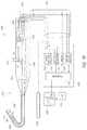
- such techniquesare typically performed by a clinician who introduces a catheter having an ablative tip to the endocardium via the venous vasculature, positions the ablative tip adjacent to what the clinician believes to be an appropriate region of the endocardium based on tactile feedback, mapping electrocardiogram (ECG) signals, anatomy, and/or fluoroscopic imaging, actuates flow of an irrigant to cool the surface of the selected region, and then actuates the ablative tip for a period of time and at a power believed sufficient to destroy tissue in the selected region.
- ECGmapping electrocardiogram
- the clinicianstrives to establish stable and uniform contact between the electrode(s) and the tissue to be ablated.
- systems and methodsare provided for assessing or determining a level or quality of contact between a distal end portion of a medical instrument (such as an ablation catheter) and a target region (such as cardiac tissue or other body tissue).
- the contact assessment or determinationmay be performed prior to delivery of ablative energy to cardiac tissue so or may be performed during energy delivery so as to increase the likelihood that a treatment procedure (for example, lesion formation) is effective and to promote safety (for example, to avoid perforation, overheating or other damage to the target region).
- the contact assessment or determinationmay be performed by a contact sensing subsystem of an overall treatment system and may be executed by a processor that is specifically configured to execute program instructions stored on a computer-readable medium.
- a signal source of the contact sensing subsystemmay be configured to generate one or more signals at least two different frequencies and to apply the signals across a pair of electrode members separated by a gap positioned along the distal end portion of the medical instrument. Electrical measurements (such as voltage and/or current measurements or impedance measurements) may be obtained between the pair of electrode members and the level or quality of contact between the distal end portion of the medical instrument and the target region may be determined (for example, calculated) based, at least in part, on the electrical measurements.
- bipolar contact impedance magnitudeis determined at a first frequency
- bipolar contact phase angleis determined at a second frequency
- the slope between bipolar contact impedance magnitudeis determined between the first frequency and the second frequency and a combination of the determinations is used to generate an overall assessment of contact quality.
- a real-time indicator of the contact qualitymay be output on a display for a physician or other clinical professional to easily view and to which the physician or other clinical professional can easily react or respond.
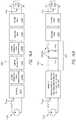
- a systemcomprises at least one signal source configured to deliver at least a first frequency and a second frequency to a pair of electrodes or electrode portions of a combination electrode or electrode assembly.
- the systemalso comprises a processing device configured to: obtain electrical measurements while the first frequency and the second frequency are being applied to the pair of electrodes by the signal source, process the electrical (for example, voltage, current, impedance) measurements obtained at the first frequency and the second frequency, and determine whether the pair of electrodes is in contact with tissue based on said processing of the electrical (for example, impedance) measurements.
- the pair of electrodesmay be positioned along a medical instrument (for example, at a distal end portion of an ablation catheter).
- the pair of electrodesmay comprise radiofrequency electrodes and the at least one signal source may comprise one, two or more sources of radiofrequency energy.
- the signal sourcemay comprise a first signal source configured to generate, deliver or apply signals to the pair of electrodes having a frequency configured for tissue ablation and a second signal source configured to generate, deliver or apply signals to the pair of electrodes having frequencies adapted for contact sensing and/or tissue type determination (for example, whether the tissue is ablated or still viable).
- the first and second signal sourcesmay be integrated within an energy delivery module (for example, RF generator) or within an elongate body or handle of a medical instrument (for example, ablation catheter).
- the second signal sourceis within a contact sensing subsystem, which may be a distinct and separate component from the energy delivery module and medical instrument or integrated within the energy delivery module or medical instrument.
- the systemcomprises an energy source configured to generate, deliver or apply signals to at least a pair of electrode members (and also to a ground pad or reference electrode) to deliver energy having a frequency configured for tissue ablation or other treatment and a signal source configured to generate, deliver or apply signals to the pair of electrode members (and not to a ground pad or reference electrode) having frequencies adapted for contact sensing and/or tissue type determination (for example, whether the tissue is ablated or still viable).
- the signals generated by the signal sourcemay comprise constant current AC excitation signals or AC voltage excitation signals.
- the excitation signalsmay advantageously be outside the frequency range of the ablative frequencies and/or electrogram mapping frequencies.
- the energy source and the signal sourcemay both be integrated within an energy delivery module (for example, RF generator) or one of the sources (for example, the signal source) may be incorporated within an elongate body or handle of a medical instrument (for example, ablation catheter).
- the signal sourceis within a contact sensing subsystem, which may be a distinct and separate component from the energy delivery module and medical instrument or integrated within the energy delivery module or medical instrument.
- a single sourceconfigured for applying signals having frequencies adapted for ablation or other treatment and configured for applying signals having frequencies adapted for contact sensing or tissue type determination functions is used.
- Signals having the treatment frequenciesmay also be delivered to a ground pad or reference electrode.
- the systemconsists essentially of or comprises a medical instrument (for example, an energy delivery device), one or more energy sources, one or more signal sources and one or more processing devices.
- the medical instrumentfor example, energy delivery catheter
- the medical instrumentmay comprise an elongate body having a proximal end and a distal end and a pair of electrodes or electrode portions (for example, a combination, or split-tip, electrode assembly) positioned at the distal end of the elongate body.
- the pair of electrodescomprises or consists essentially of a first electrode positioned on the elongate body and a second electrode positioned adjacent (for example, proximal of) the first electrode.
- the first electrode and the second electrodemay be adapted to contact tissue of a subject and provide energy to the tissue to heat (for example, ablate or otherwise treat) the tissue at a depth from the surface of the tissue.
- the pair of electrodescomprises an electrically insulating gap positioned between the first electrode and the second electrode, the electrically insulating gap comprising a gap width separating the first and second electrodes.
- a separator(for example, a capacitor or insulation material) may be positioned within the electrically insulating gap.
- the one or more signal sourcesmay be configured to deliver signals over a range of frequencies (for example, frequencies within a radiofrequency range).
- the processing deviceis configured to execute specific program instructions stored on a non-transitory computer-readable storage medium to: obtain impedance or other electrical measurements while different frequencies of energy within the range of frequencies are being applied to the pair of electrodes by a signal source, process the impedance or other electrical measurements obtained at the first frequency and the second frequency, and determine whether at least one of (for example, the distal-most electrode) the pair of electrodes is in contact with tissue based on said processing of the impedance or other electrical measurements.
- the impedance measurementsconstitute bipolar contact impedance between the pair of electrodes or between the electrode members of a combination electrode assembly and not the impedance between an electrode and target tissue.
- the impedance or other electrical measurementsdo not involve passing current to one or more patch or reference electrodes positioned at a location external to the medical instrument or at a location remote from the target tissue (for example, at a location on the skin of a patient at the neck, torso and/or leg).
- the medical instrumentconsists essentially of or comprises a radiofrequency ablation catheter and the first and second electrodes or electrode portions comprise radiofrequency electrodes.
- the signal source(s)may comprise a radiofrequency (RF) generator.
- the range of frequencies that is delivered by the signal source(s)comprises at least a range between 1 kHz and 5 MHz (for example, between 5 kHz and 1000 kHz, between 10 kHz and 500 kHz, between 5 kHz and 800 kHz, between 20 kHz and 800 kHz, between 50 kHz and 5 MHz, between 100 kHz and 1000 kHz, and overlapping ranges thereof).
- the signal source(s)may also be configured to deliver frequencies below and above this range.
- the frequenciesmay be at least greater than five times or at least greater than ten times the electrogram mapping frequencies so as not to interfere with high-resolution mapping images or functions obtained by the first and second electrodes or electrode portions.
- the different frequencies at which impedance measurements are obtainedconsists only of two discrete frequencies.
- the different frequenciescomprise two or more discrete frequencies.
- the processing deviceis configured to obtain impedance measurements while a full sweep of frequencies from a minimum frequency to a maximum frequency of the range of frequencies is applied to the pair of electrodes or electrode portions.
- the range of frequenciesis between 5 kHz and 1000 kHz.
- the second frequencymay be different from (for example, higher or lower than) the first frequency.
- the frequencies used for contact sensing or determinationare outside (for example, below) the frequency range of the ablative frequencies.
- the systemmay comprise an ablative energy source (for example, signal source such as an RF generator) configured to deliver signals to the pair of electrodes (and possibly also to a ground pad or reference electrode) to generate energy sufficient to ablate or otherwise treat tissue (such as cardiac tissue).
- the processing deviceis configured to adjust one or more energy delivery parameters of the ablative energy based on a determination of whether at least one of the pair of electrodes is in contact with tissue and/or is configured to terminate energy delivery based on a determination of whether at least one of the pair of electrodes is in contact with tissue or that contact has been lost.
- the ablative energy source and the at least one signal sourcecomprise a single source.
- the signal sourcecomprises a first source and the ablative energy source comprises a second source that is separate and distinct from the first source.
- the processingis performed in the time domain. In some embodiments, the processing is performed in the frequency domain. Portions of the processing may be performed in both the time domain and the frequency domain.
- the processing deviceis configured to execute specific program instructions stored on a non-transitory computer-readable storage medium to generate an output indicative of contact.
- the processing devicemay be configured to cause the generated output to be displayed on a display (for example an LCD or LED monitor) in communication with the processing device.
- the outputcomprises textual information, quantitative information (for example, numeric information, binary assessment of whether contact exists or not) and/or a qualitative information (for example, color or other information indicative of a level of contact).
- the outputcomprises haptic or tactile output or feedback generated by one or more haptic devices.
- the haptic or tactile outputmay be provided to a handle of the medical instrument (for example, ablation catheter) or to a separate wearable or handheld device.
- the haptic or tactile output or feedbackmay comprise vibrations, forces or other motions.
- the haptic or tactile output or feedbackis provided by an amount of opposition or resistance force perceived or felt by a user indicative of a level of contact as a steerable distal end portion of the medical instrument is being steered.
- the haptic or tactile output or feedbackmay be provided prior to and/or during energy delivery.
- the haptic output or feedbackmay be based on contact determinations made by the processing device based on impedance measurements between the pair of electrodes and/or based on temperature measurements received from one or more temperature-measurement devices along the medical instrument.
- the haptic output or feedbackmay be used to indicate that contact has occurred, a level of contact or a change in level of contact and/or that contact has been lost or is likely about to be lost.
- the processing devicemay be configured to adjust one or more energy delivery parameters based on the determination of whether the medical instrument (for example, at least one of the pair of electrodes) is in contact with tissue (for example, above a threshold level of contact) or that contact has been lost (for example, below a threshold level of contact).
- a systemcomprises a signal source configured to deliver signals having a range of frequencies and a processing device configured to execute specific program instructions stored on a non-transitory computer-readable storage medium to: obtain impedance (for example, bipolar contact impedance) or other electrical measurements while different frequencies of energy are being applied to a pair of electrodes (for example, combination electrode, or split-tip, electrode assembly) by the signal source, compare the impedance measurements obtained at the different frequencies of energy; and determine whether or not tissue in contact with at least one of the pair of electrodes has been ablated.
- impedancefor example, bipolar contact impedance
- a pair of electrodesfor example, combination electrode, or split-tip, electrode assembly
- the range of frequencies over which contact determination is madeis between 5 kHz and 1000 kHz.
- the different frequenciesconsist of two discrete frequencies in one embodiment or may comprise two or more discrete frequencies in other embodiments.
- the processing devicemay be configured to obtain impedance measurements while a full sweep of frequencies from a minimum frequency to a maximum frequency of the range of frequencies (for example, 5 kHz to 1000 kHz) is applied to the pair of electrodes.
- one component of an impedance measurementfor example, impedance magnitude
- a second component of a different impedance measurementfor example, phase angle
- a comparisonfor example, derivative of impedance versus frequency, delta or slope of impedance vs. frequency
- impedance magnitude measurements at two or more different frequenciesmay also be obtained.
- a weighted combination of various impedance measurements between the pair of electrodes at two or more different frequenciesmay be calculated by the processing device and used by the processing device to determine an overall contact level or state.
- the impedance measurementsmay be obtained directly or may be calculated based on electrical parameter measurements, such as voltage and/or current measurements.
- the impedance measurementscomprise bipolar impedance measurements.
- the processing deviceis configured to execute specific program instructions stored on a non-transitory computer-readable storage medium to generate an output indicative of tissue type based on the determination of whether or not tissue in contact with at least one of the pair of electrodes has been ablated.
- the processing devicemay be configured to cause the generated output to be displayed on a display in communication with the processing device.
- the outputmay comprise one or more of textual information, a color or other qualitative information, and numerical information.
- the processing deviceis configured to adjust one or more energy delivery parameters based on the determination of whether the tissue in contact with the pair of electrodes has been ablated and/or is configured to terminate energy delivery based on the determination of whether tissue in contact with the pair of electrodes has been ablated.
- a system for determining whether a medical instrument is in contact with tissue based, at least in part, on impedance measurementscomprises a signal source configured to deliver signals having different frequencies to a pair of electrodes of a medical instrument and a processing device configured to process a resulting waveform that formulates across the pair of electrodes to obtain impedance measurements at a first frequency and a second frequency and determine a ratio between the magnitude of the impedance at the second frequency and the first frequency. If the determined ratio is below a predetermined threshold indicative of contact, the processing device is configured, upon execution of stored instructions on a computer-readable medium, to generate a first output indicative of contact.
- the processing deviceis configured to, upon execution of stored instructions on a computer-readable medium, generate a second output indicative of no contact.
- the signal sourcecomprises a radiofrequency energy source.
- the first and second frequenciesmay be between 5 kHz and 1000 kHz.
- the signal sourceis configured to generate signals having a frequency adapted for tissue ablation.
- the systemcomprises a second signal source (or an ablative energy source) configured to generate signals having a frequency adapted for tissue ablation.
- the frequency adapted for tissue ablationmay be between 400 kHz and 600 kHz (for example, 400 kHz, 450 kHz, 460 kHz, 480 kHz, 500 kHz, 550 kHz, 600 KHz, 400 KHZ-500 kHz, 450 kHz-550 kHz, 500 kHz-600 kHz, or overlapping ranges thereof).
- the predetermined thresholdis a value between 0.5 and 0.9.
- Processing the waveformsmay comprise obtaining voltage and/or current measurements and calculating impedance measurements based on the voltage and/or current measurements or directly obtaining impedance measurements.
- a method of determining whether a medical instrument is in contact with a target region (for example, tissue) based, at least in part, on electrical measurements (for example, impedance measurements),may comprise applying signals having a first frequency and a second frequency to a pair of electrodes or electrode portions of the medical instrument, processing a resulting waveform to obtain impedance measurements at the first frequency and the second frequency, and determining a ratio between the magnitude of the impedance at the second frequency and the first frequency. If the determined ratio is below a predetermined threshold indicative of contact, the method comprises generating a first output indicative of contact. If the determined ratio is above the predetermined threshold, the method comprises generating a second output indicative of no contact. The method may further comprise applying a signal adapted to cause ablative energy to be delivered by the pair of electrodes or electrode portions sufficient to ablate the target region (for example, cardiac tissue or other body tissue).
- a system for determining a contact state of a distal end portion of a medical instrument with a target region (for example, tissue) based, at least in part, on electrical measurementscomprises a signal source configured to generate at least one signal having a first frequency and a second frequency to be applied to a pair of electrode members of a combination electrode assembly.
- the signal sourcemay be a component of a contact sensing or detection subsystem or an energy delivery module, such as a radiofrequency generator.
- the systemalso comprises a processor or other computing device configured to, upon execution of specific program instructions stored in memory or a non-transitory computer-readable storage medium, cause the signal source to generate and apply the at least one signal to the pair of electrode members.
- the signalmay be a single multi-tone waveform or signal or multiple waveforms or signals having a single frequency.
- the processormay be configured to process a resulting waveform that formulates across the pair of electrode members to obtain a first electrical measurement at the first frequency and to process the resulting waveform that formulates across the pair of electrode members to obtain a second electrical measurement at the second frequency of the plurality of frequencies.
- the processoris further configured to: determine an impedance magnitude based on the first electrical measurement (for example, voltage and/or current measurement), determine an impedance magnitude and a phase based on the second electrical measurement, and calculate a contact indication value indicative of a state of contact between the distal end portion of the medical instrument and the target region based on a criterion combining the impedance magnitude based on the first electrical measurement, a ratio of the impedance magnitudes based on the first electrical measurement and the second electrical measurement, and the phase based on the second electrical measurement.
- the first and second electrical measurementsmay comprise voltage and/or current measurements or direct impedance measurements between the pair of electrode members.
- the first and second electrical measurementsdo not comprise direct measurements of electrical parameters or a degree of coupling between an electrode and tissue but are measurements between two electrode members.
- Impedance measurementsmay be calculated based on the voltage and/or current measurements or may be directly obtained or measured by an instrument or device configured to output impedance measurements.
- the impedance measurementsmay comprise complex impedance measurements composed of real and imaginary components (for example, impedance magnitude and phase angle measurements or resistance and reactance measurements).
- the impedance measurementscomprise bipolar contact impedance measurements between the two electrode members.
- the criterioncomprises a weighted combination of the impedance magnitude based on the first electrical measurement, a ratio of the impedance magnitudes based on the first and second electrical measurements, and the phase based on the second electrical measurement.
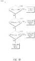
- the criterioncomprises an if-then case conditional criterion, such as described in connection with FIGS. 11 and 11A .
- only one impedance measurement or calculationfor example, only impedance magnitude, only slope between impedance magnitude values, or only phase
- only two types of impedance measurements or calculationsare used to determine the contact state.
- a system for determining whether a medical instrument is in contact with a target region (for example, tissue) based, at least in part, on impedance measurementsconsists essentially of or comprises a signal source configured to generate one or more signals having a first frequency and a second frequency to a pair of electrodes (for example, positioned at a distal end of a medical instrument, catheter or probe) and a processing device configured to execute specific program instructions stored on a non-transitory computer-readable storage medium to process a resulting waveform that formulates across the pair of electrodes to obtain impedance measurements at the first frequency and the second frequency.
- a signal sourceconfigured to generate one or more signals having a first frequency and a second frequency to a pair of electrodes (for example, positioned at a distal end of a medical instrument, catheter or probe) and a processing device configured to execute specific program instructions stored on a non-transitory computer-readable storage medium to process a resulting waveform that formulates across the pair of electrodes to obtain impedance measurements at the
- processing deviceis configured to, upon execution of stored instructions on the computer-readable storage medium, generate a first output indicative of contact. If the impedance magnitude at the first and/or second frequency is below a predetermined threshold indicative of no contact, the processing device is configured to, upon execution of stored instructions on the computer-readable storage medium, generate a second output indicative of no contact.
- Processing the waveformsmay comprise obtaining voltage and/or current measurements and calculating impedance measurements based on the voltage and/or current measurements or directly obtaining impedance measurements.
- a method of determining whether a medical instrument is in contact with a target region (for example, tissue) based, at least in part, on impedance measurementscomprises delivering at least one signal having a first frequency and a second frequency (for example, a multi-tonal waveform) to a pair of electrodes or electrode portions and processing a resulting waveform that formulates across the pair of electrodes to obtain impedance measurements at the first frequency and the second frequency. If the impedance magnitude at the first frequency and/or second frequency is above a predetermined threshold indicative of contact, the method comprises generating a first output indicative of contact. If the impedance magnitude at the first frequency and/or second frequency is below a predetermined threshold indicative of no contact, the method comprises generating a second output indicative of no contact. The method may further comprise applying a signal adapted to cause ablative energy to be delivered by the pair of electrodes or electrode portions sufficient to ablate or otherwise treat cardiac or other body tissue.
- a method of determining whether a medical instrument is in contact with a target region (for example, tissue) based, at least in part, on impedance measurementsmay comprise applying a signal comprising a multi-tone waveform having a first frequency and a second frequency to a pair of electrodes, processing the resulting waveform to obtain impedance measurements at the first frequency and the second frequency, comparing values of the impedance measurements at the first frequency and the second frequency to a known impedance of blood or a blood and saline mixture (or other known tissue impedance), comparing values of the impedance measurements at the first and second frequency to each other; and generating an output indicative of whether or not the medical instrument is in contact with tissue based on said comparisons.
- the methodmay further comprise applying a signal adapted to cause ablative energy to be delivered by the pair of electrodes sufficient to ablate or otherwise treat cardiac or other body tissue.
- a system for determining whether a medical instrument is in contact with tissue based, at least in part, on impedance measurementsmay comprise a signal source configured to generate a multi-tone waveform or signal having a first frequency and a second frequency to a pair of electrodes (for example, at a distal end of a split-tip electrode catheter); and a processing device.
- the processing devicemay be configured to, upon execution of stored instructions on a computer-readable storage medium, process the resulting waveform to obtain impedance measurements at the first frequency and the second frequency, compare values of the impedance measurements at the first frequency and the second frequency to a known impedance of blood or a blood and saline mixture, compare values of the impedance measurements at the first and second frequency to each other and/or generate an output indicative of whether or not the medical instrument is in contact with tissue based on said comparisons.
- a method of determining whether a medical instrument comprising a pair of electrodes or electrode portions is in contact with a target region (for example, tissue) based, at least in part, on impedance measurementscomprises applying at least one signal having a plurality of frequencies (for example, a multi-tonal waveform) to a pair of electrodes of a medical instrument, and processing a resulting waveform that formulates across the pair of electrodes to obtain impedance measurements at a first frequency and a second frequency of the plurality of frequencies. If a variation of the impedance measurements across the range of frequencies has a model whose parameter values are indicative of contact, the method comprises generating a first output indicative of contact.
- a target regionfor example, tissue
- impedance measurementscomprises applying at least one signal having a plurality of frequencies (for example, a multi-tonal waveform) to a pair of electrodes of a medical instrument, and processing a resulting waveform that formulates across the pair of electrodes to obtain impedance measurements at a first frequency and
- the methodcomprises generating a second output indicative of no contact.
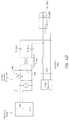
- the modelmay comprise a fitting function or a circuit model such as shown in FIG. 5B .
- the methodmay further comprise applying a signal adapted to cause ablative energy to be delivered by the pair of electrodes sufficient to ablate or otherwise treat cardiac or other body tissue.
- a system for determining whether a medical instrument is in contact with tissue based, at least in part, on impedance measurementscomprises a signal source configured to generate at least one signal having a first frequency and a second frequency to a pair of electrodes and a processing device.
- the processing devicemay be configured to, upon execution of stored instructions on a computer-readable storage medium, apply at least one signal having a plurality of frequencies to a pair of electrodes of a medical instrument and process a resulting waveform that formulates across the pair of electrodes to obtain impedance measurements at a first frequency and a second frequency of the plurality of frequencies. If a variation of the impedance measurements across the range of frequencies follows a model whose parameter values are indicative of contact the processor is configured to generate a first output indicative of contact.
- processing the waveforms to obtain impedance measurementsmay comprise obtaining voltage and/or current measurements and calculating impedance measurements based on the voltage and/or current measurements or directly obtaining impedance measurements.
- a method of determining whether tissue has been ablated by an ablation catheter comprising a pair of electrodescomprises applying one or more signals having a first frequency and a second frequency (for example, a multi-tonal waveform) to a pair of electrodes along the ablation catheter and processing a resulting waveform that formulates across the pair of electrodes to obtain impedance measurements at the first frequency and the second frequency.
- the methodmay comprise assessing absolute change in the impedance as well as the slope or ratio between impedance.
- the methodcomprises generating a first output indicative of ablated tissue. If the first impedance measurement at the first and/or second frequency is greater than a known impedance level of blood and if a ratio of the second impedance measurement to the first impedance measurement is above a predetermined threshold, the method comprises generating a second output indicative of viable tissue. Processing the waveforms to obtain impedance measurements may comprise obtaining voltage and/or current measurements and calculating impedance measurements based on the voltage and/or current measurements or directly obtaining impedance measurements. The method may further comprise applying a signal adapted to cause ablative energy to be delivered by the pair of electrodes sufficient to ablate or otherwise treat cardiac or other body tissue.
- a phase of the impedance measurements at the first frequency and/or second frequencyis compared to a known phase response for blood or a blood and saline mixture and utilized in conjunction with the magnitude values of the impedance measurements to generate an output indicative of whether or not the medical instrument is in contact with tissue.
- a system for determining whether tissue has been ablated by an ablation catheter comprising a pair of electrodes or electrode portionsmay comprise a signal source configured to generate at least one signal having a first frequency and a second frequency to a pair of electrodes along the ablation catheter and a processing device.
- the processing devicemay be configured to, upon execution of stored instructions on a computer-readable storage medium, process a resulting waveform that formulates across the pair of electrodes to obtain impedance measurements at the first frequency and the second frequency. If the first impedance measurement at the first and/or second frequency is greater than a known impedance level of blood and if a ratio of the second impedance measurement to the first impedance measurement is above a predetermined threshold, the processing device is configured to generate a first output indicative of ablated tissue. If a ratio of the second impedance measurement to the first impedance measurement is below a predetermined threshold, the processor is configured to generate a second output indicative of viable (for example, unablated) tissue. Processing the waveforms to obtain impedance measurements may comprise obtaining voltage and/or current measurements and calculating impedance measurements based on the voltage and/or current measurements or directly obtaining impedance measurements.
- Processing the resulting waveformmay comprise applying a transform (for example, a Fourier transform) to the waveform to obtain the impedance measurements.
- a transformfor example, a Fourier transform
- the first frequency and the second frequencyare within a range between 5 kHz and 1000 kHz.
- the second frequencyis higher than the first frequency.
- the impedance measurementsmay be obtained simultaneously or sequentially.
- the second frequencymay be at least 20 kHz higher than the first frequency.
- the first frequencyis between 10 kHz and 100 kHz (for example, between 10 KHz and 30 kHz, between 15 kHz and 40 kHz, between 20 kHz and 50 kHz, between 30 kHz and 60 kHz, between 40 kHz and 80 kHz, between 50 kHz and 90 kHz, between 60 kHz and 100 kHz, overlapping ranges thereof, 20 kHz or any values from 10 kHz and 100 kHz) and the second frequency is between 400 kHz and 1000 kHz (for example, between 400 kHz and 600 kHz, between 450 kHz and 750 kHz, between 500 kHz and 800 kHz, between 600 kHz and 850 kHz, between 700 kHz and 900 kHz, between 800 kHz and 1000 kHz, overlapping ranges thereof, 800 kHz, or any values from 400 kHz to 1000 kHz).
- the second frequencyis between 400 kHz and 1000 kHz (for example, between 400
- the predetermined thresholdmay have a value between 0.5 and 0.9.
- generating a first output and generating a second outputfurther comprises causing the first output or the second output to be displayed on a display (for example via one or more display drivers).
- the outputmay comprise textual information, quantitative measurements and/or qualitative assessments indicative of contact state.
- the outputincludes an amount of contact force corresponding to the level of contact (for example, grams of force).
- a method of determining whether a medical instrument having a pair of electrodes or electrode portions is in contact with a target region (for example, tissue) based, at least in part, on impedance measurementsmay comprise obtaining a first impedance measurement at a first frequency within a range of frequencies, obtaining a second impedance measurement at a second frequency within the range of frequencies and obtaining a third impedance measurement at a third frequency within the range of frequencies. If a variation of the impedance measurements across the range of frequencies is above a predetermined threshold indicative of contact, the method comprises generating a first output indicative of contact. If the variation of the impedance measurements across the range of frequencies is below the predetermined threshold, the method comprises generating a second output indicative of no contact.
- the impedance measurementsmay be calculated based on voltage and/or current measurements or may be directly-measured impedance measurements.
- the range of frequenciesmay be between 5 kHz and 5 MHz (for example, between 5 kHz and 1000 kHz, between 1 MHz and 3 MHz, between 2.5 MHz and 5 MHz, or overlapping ranges thereof).
- the first frequencyis between 10 kHz and 100 kHz (for example, between 10 KHz and 30 kHz, between 15 kHz and 40 kHz, between 20 kHz and 50 kHz, between 30 kHz and 60 kHz, between 40 kHz and 80 kHz, between 50 kHz and 90 kHz, between 60 kHz and 100 kHz, overlapping ranges thereof, 20 kHz or any values from 10 kHz and 100 kHz) and the second frequency is between 400 kHz and 1000 kHz (for example, between 400 kHz and 600 kHz, between 450 kHz and 750 kHz, between 500 kHz and 800 kHz, between 600 kHz and 850 kHz, between 700 kHz and 900 kHz,
- the predetermined thresholdmay be a value between 0.5 and 0.9.
- generating a first output and generating a second outputcomprises causing the first output or the second output to be displayed on a display.
- the outputmay comprise textual information indicative of contact.
- the outputcomprises a quantitative measurement and/or qualitative assessment of contact.
- the methodmay further comprise applying a signal adapted to cause ablative energy to be delivered by the pair of electrodes or electrode portions sufficient to ablate or otherwise treat cardiac or other body tissue.
- a medical treatment systemcomprises a medical instrument comprising a proximal end portion, a distal end portion and an elongate body extending from the proximal end portion to the distal end portion.
- the proximal end portioncomprises a handle configured to be gripped by a hand of an operator.
- the handlecomprises an external steering actuator that is manually operable by the operator, a sensor configured to sense movement of the steering actuator, a tactile stimulation element configured to provide tactile stimulation to the handle, and an internal steering actuation member configured to effect steering of the distal end portion of the medical instrument based on movement of the external steering actuator.
- the systemalso comprises a control unit configured to receive signals from the sensor indicative of movement of the external steering actuator by the operator and to output signals to actuate a tactile stimulation element and the internal steering actuation member in response to the received signals from the sensor so as to generate the opposition force and so as to effect the steering of the distal end portion.
- the medical instrumentcomprises an ablation catheter.
- the external steering actuatormay comprise a rotatable mechanism, such as a knob, or a push-pull mechanism, such as a plunger or sliding bar. Other mechanisms may also be used to actuate steering as desired and/or required.
- the distal end portion of the medical instrumentmay comprise a steering plate, the handle may comprise a steering capstan, and steering wires may extend from the steering capstan to the steering plate to effect the steering of the distal end portion.
- the internal steering actuation membercomprises a first motor (for example, power steering motor) coupled to the steering capstan and configured to cause rotation of the steering capstan based on the signals received from the sensor.
- the control unitcomprises a first motor driver configured to actuate the power steering motor.
- Other steering members other than a plate and capstanmay be substituted as desired and/or required.
- the tactile stimulation elementcomprises a second motor (for example, opposition force motor).
- the control unitmay comprise a second motor driver configured to actuate the opposition force motor to provide the opposition force (or other haptic output or feedback) to the handle.
- the distal end portion of the medical instrumentcomprises a high-resolution electrode assembly comprising a first electrode portion and second electrode portion spaced apart and insulated from the first electrode portion (for example, a split-tip electrode assembly or combination radiofrequency electrode).
- the control unitmay comprise a contact detection subsystem or module configured to receive signals from the high-resolution electrode assembly and the control unit (for example, processor) of the contact detection subsystem or module or a separate processor may be configured (for example, specifically programmed with instructions stored in or on a non-transitory computer-readable medium) to determine a level of contact or a contact state with tissue (for example, cardiac tissue) based on the received signals from the high-resolution electrode assembly and to modulate the opposition force provided by the opposition force motor based, at least in part, on the determined level of contact, or the contact state.
- the control unitmay further comprise a power delivery module configured to apply radiofrequency power to the high-resolution electrode assembly at a level sufficient to effect ablation of tissue in contact with at least a portion of the distal end
- control unitfor example, processor
- the control unitis configured to generate output indicative of the level of contact for display on a display coupled to the control unit (for example, via one or more display drivers).
- the outputis based on a contact function determined based on one or more criteria combining multiple electrical parameter measurements (such as voltage measurements, current measurements or impedance measurements).
- the contact functionis determined by summing a weighted combination of impedance (for example, bipolar impedance) measurements that are directly measured or that are calculated based on voltage and/or current measurements.
- the contact functionis based on one or more if-then case conditional criteria.
- the impedance measurementscomprise one or more of an impedance magnitude determined by the contact detection subsystem at a first frequency, a ratio of impedance magnitudes at the first frequency and a second frequency and a phase of a complex impedance measurement at the second frequency.
- the second frequencymay be higher than the first frequency (for example, at least 20 kHz higher than the first frequency). In some embodiments, the first frequency and the second frequency are between 5 kHz and 1000 kHz.
- the first frequencyis between 10 kHz and 100 kHz (for example, between 10 KHz and 30 kHz, between 15 kHz and 40 kHz, between 20 kHz and 50 kHz, between 30 kHz and 60 kHz, between 40 kHz and 80 kHz, between 50 kHz and 90 kHz, between 60 kHz and 100 kHz, overlapping ranges thereof, 20 kHz or any values from 10 kHz and 100 kHz) and the second frequency is between 400 kHz and 1000 kHz (for example, between 400 kHz and 600 kHz, between 450 kHz and 750 kHz, between 500 kHz and 800 kHz, between 600 kHz and 850 kHz, between 700 kHz and 900 kHz, between 800 kHz and 1000 kHz, overlapping ranges thereof, 800 kHz, or any values from 400 kHz to 1000 kHz); however, other frequencies may be used as desired and/or required. In some embodiments, other frequencies may
- the handle of the medical instrumentfurther comprises a motion detection element (for example, at least one of an accelerometer and a gyroscope).
- the first motoris configured to be actuated only when the motion detection element is detecting motion of the handle.
- a method of determining a contact state of a distal end portion of a medical instrument with a target region, for example, tissuecomprises applying at least one signal having a plurality of frequencies to a pair of electrodes or electrode portions of a combination electrode assembly positioned along a distal end portion of a medical instrument.
- the methodcomprises processing a resulting waveform that formulates across the pair of electrodes to obtain a first impedance measurement at a first frequency of the plurality of frequencies and processing the resulting waveform that formulates across the pair of electrodes to obtain a second impedance measurement at a second frequency of the plurality of frequencies.
- the methodfurther comprises determining a magnitude of the first impedance measurement, determining a magnitude and a phase of the second impedance measurement and applying a contact function (for example, via execution of a computer program stored on a non-transitory computer storage medium) to calculate a contact indication value indicative of a state of contact between the distal end portion of the medical instrument and the target region (for example, cardiac tissue).
- the contact functionmay be determined by summing a weighted combination of the magnitude of the first impedance measurement, a ratio of the magnitudes of the first impedance measurement and the second impedance measurement, and the phase of the second impedance measurement.
- the first frequency and the second frequencyare different.
- the second frequencyis higher than the first frequency.
- the methodmay further comprise generating output corresponding to the contact indication value for display on a display monitor (for example, via one or more display drivers).
- the outputcomprises a qualitative and/or a quantitative output.
- the outputmay comprise a numerical value between 0 and 1 or between 0 and 1.5, with values above 1 indicating excessive contact.
- the outputcomprises a percentage value or a number corresponding to an amount of contact force (for example, grams of contact force).
- the outputmay comprise a color and/or pattern indicative of the contact state and/or one or more of a gauge, a bar, or a scale.
- the outputcomprises a haptic or other tactile output.
- the methodmay further comprise applying a signal adapted to cause ablative energy to be delivered by the pair of electrodes or electrode portions sufficient to ablate or otherwise treat cardiac or other body tissue.
- a system for determining a contact state of a distal end portion of a medical instrument with a target regionconsists essentially of or comprises a signal source configured to generate at least one signal having a first frequency and a second frequency to be applied to a pair of electrode members of a combination electrode assembly (for example, two electrode members separated by a gap).
- the systemalso consists essentially of or comprises a processing device configured to (a) cause the signal source to generate and apply the at least one signal to the pair of electrode members, (b) process a resulting waveform that formulates across the pair of electrode members to obtain a first electrical measurement at the first frequency, (c) process the resulting waveform that formulates across the pair of electrode members to obtain a second electrical measurement at the second frequency of the plurality of frequencies, (d) determine an impedance magnitude based on the first electrical measurement, (e) determine an impedance magnitude and a phase based on the second electrical measurement, and (f) calculate a contact indication value indicative of a state of contact between the distal end portion of the medical instrument and the target region based on a criterion combining the impedance magnitude based on the first electrical measurement, a ratio of the impedance magnitudes based on the first and second electrical measurements, and the phase based on the second electrical measurement.
- a processing deviceconfigured to (a) cause the signal source to generate and apply the at least one signal
- the electrical measurementsmay comprise voltage, current, and/or other electrical parameter measurements from which impedance measurements (such as impedance magnitude or phase) may be calculated or may comprise directly-obtained impedance measurements.
- the criterionmay comprise a weighted combination of the impedance magnitude based on the first electrical measurement, a ratio of the impedance magnitudes based on the first and second electrical measurements, and the phase based on the second electrical measurement or the criterion may comprise an if-then case conditional criterion.
- the systemfurther comprises the medical instrument, which may be a radiofrequency ablation catheter.
- the first frequency and the second frequencymay be different.
- the second frequencyis higher than the first frequency.
- the second frequencyis lower than the first frequency.
- the first frequency and the second frequencyare between 5 kHz and 1000 kHz (for example, between 5 kHz and 50 kHz, between 10 kHz and 100 kHz, between 50 kHz and 200 kHz, between 100 kHz and 500 kHz, between 200 kHz and 800 kHz, between 400 kHz and 1000 kHz, or overlapping ranges thereof).
- the two frequenciesare at least 20 kHz apart in frequency.
- the processoris further configured to generate output corresponding to the contact indication value for display on a display monitor, upon execution of specific instructions stored in or on a computer-readable medium.
- the outputcomprises a numerical value between 0 and 1.
- the outputcomprises a qualitative output (such as a color and/or pattern indicative of the contact state).
- the outputcomprises one or more of a gauge, a bar, a meter or a scale.
- the outputcomprises a virtual gauge having a plurality of regions (for example, two, three, four, five or more than five regions or segments) indicative of varying levels of contact, or contact states. The plurality of regions may be represented in different colors. Each of the plurality of regions may correspond to a different range of numerical values indicative of varying levels of contact.
- the outputcomprises a haptic, or tactile, output.
- a system for displaying a contact state of a distal tip of a medical instrument with a target region (for example, body tissue) on a patient monitorcomprises a processor configured to generate output for display on the patient monitor.
- the outputmay be generated on a graphical user interface on the patient monitor.
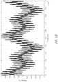
- the outputcomprises a graph that displays a contact function indicative of a contact state between a distal tip of a medical instrument and body tissue calculated by a processing device based, at least in part, on impedance measurements obtained by the medical instrument.
- the graphmay be a scrolling waveform.
- the outputalso comprises a gauge separate from the graph that indicates a real-time state of contact corresponding to a real-time numerical value of the contact function displayed by the graph.
- the gaugeincludes a plurality of regions indicative of varying contact states.
- each one of the plurality of regionsis optionally displayed in a different color or graduation to provide a qualitative indication of the real-time state of contact.
- the gaugeconsists of three regions or segments. The three regions may be colored red, yellow and green.
- the gaugeconsists of four regions or segments. The four regions may be colored red, orange, yellow and green.
- Each of the plurality of regionsmay correspond to a different range of numerical values indicative of the current contact state.
- the gaugemay comprise a pointer that indicates a level on the gauge corresponding to the real-time numerical value of the contact function.
- the real-time numerical valuemay range between 0 and 1 or between 0 and 1.25 or between 0 and 1.5.
- the gaugemay comprise a contact indicator of the quality of tissue-electrode contact calculated based on bipolar impedance magnitude, bipolar impedance-frequency slope and bipolar impedance phase.
- the outputmay also comprise other graphs or waveforms of individual components of impedance measurements (for example, impedance magnitude and phase) at multiple frequencies or of comparisons (for example, a slope) between two impedance measurements (for example, impedance magnitude at two different frequencies).
- the contact functionis calculated based on a weighted combination of a magnitude of a first impedance measurement at a first frequency, a ratio of the magnitudes of the first impedance measurement and a second impedance measurement at a second frequency different from the first frequency, and the phase of the second impedance measurement at the second frequency.
- the second frequencyis higher than the first frequency.
- the second frequencyis lower than the first frequency.
- the first frequency and the second frequencymay be between 5 kHz and 1000 kHz.
- the systemfurther comprises the patient monitor.
- a system for assessing a level of contact between a distal end portion of an ablation catheter having a pair of spaced-apart electrode members of a combination electrode assembly and target region, e.g., tissuecomprises a signal source configured to generate signals having at least a first frequency and a second frequency to be applied to the pair of spaced-apart electrode members.
- the systemalso comprises a processor configured to, upon execution of specific program instructions stored on a computer-readable storage medium, measure network parameters at an input of a network measurement circuit comprising a plurality of hardware components between the signal source and the pair of spaced-apart electrode members.
- the processormay also be configured (for example, specifically programmed, constructed or designed) to determine an aggregate effect on a measured network parameter value caused by the hardware components of the network measurement circuit, remove the aggregate effect to result in a corrected network parameter value between the pair of spaced-apart electrode members, and determine a level of contact based, at least in part, on the corrected network parameter value.
- the processoris configured to generate an output indicative of the level of contact for display.
- the signal sourcemay be located within a radiofrequency generator or within the ablation catheter.
- the processormay be configured to measure network parameters at least two frequencies (for example, two frequencies, three frequencies, four frequencies or more than four frequencies). In some embodiments, the frequencies are between 5 kHz and 1000 kHz. In embodiments involving two frequencies, the second frequency may be at least 20 kHz higher than the first frequency. For example, the first frequency may be between 10 kHz and 100 kHz and the second frequency is between 400 kHz and 1000 kHz.
- a third frequencymay be higher than the first frequency and lower than the second frequency (for example, the third frequency may be between 20 kHz and 120 kHz.).
- the network parametersmay comprise scattering parameters or other electrical parameters (such as voltage, current, impedance).
- the network parameter valuesmay comprise, for example, voltage and current values or impedance values either directly measured or determined from voltage and/or current values.
- Impedance valuesmay comprise impedance magnitude values and impedance phase values or resistance and reactance values.
- the impedance magnitude valuesmay be obtained at two or more frequencies and slopes may be determined between magnitude values at different frequencies.
- the impedance phase valuesmay be obtained at one or more frequencies.
- a method of assessing a level of contact determination of a distal end portion of an ablation catheter having a pair of spaced-apart electrode memberscomprises measuring network parameters at an input of a network parameter circuit of hardware components between a signal source and the pair of spaced-apart electrode members. The method also comprises determining an aggregate effect on a measured network parameter value determined from the network parameters caused by the hardware components, removing the aggregate effect to result in a corrected network parameter value between the pair of spaced-apart electrode members, and determining a level of contact based, at least in part, on the corrected network parameter value.
- Measuring network parametersmay comprise measuring network parameters at a plurality of frequencies. In some embodiments, determining an aggregate effect on the measured network parameter value caused by the hardware components of the network parameter circuit comprises measuring network parameters associated with each individual hardware component. In some embodiments, determining an aggregate effect on the measured network parameter value caused by the hardware components of the network parameter circuit comprises combining the network parameters of the individual hardware components into total network parameters at a plurality of frequencies. Removing the aggregate effect so as to isolate an actual network parameter value between the pair of spaced-apart electrode members may comprise de-embedding the total network parameters from a measured input reflection coefficient to result in an actual reflection coefficient corresponding to the actual network parameter value. In some embodiments, the method is performed automatically by a processor. The method may further comprise applying a signal adapted to cause ablative energy to be delivered by the pair of spaced-apart electrode members sufficient to ablate or otherwise treat cardiac or other body tissue.
- a systemcomprises a signal source (for example, a source of radiofrequency energy or excitation signals) configured to deliver signals having at least a first frequency and a second frequency to a pair of electrode members of a combination electrode assembly (for example, spaced-apart bipolar pair of electrode members) positioned along a distal end portion of a medical instrument (for example, radiofrequency ablation catheter).
- a signal sourcefor example, a source of radiofrequency energy or excitation signals
- a pair of electrode members of a combination electrode assemblyfor example, spaced-apart bipolar pair of electrode members
- a medical instrumentfor example, radiofrequency ablation catheter
- the embodiment of the systemalso comprises a processing device (for example, specific-purpose processor) configured to, upon execution of specific program instructions stored on a computer-readable storage medium: cause the signal source to generate and apply the signals to the pair of electrode members, obtain electrical measurements (for example, bipolar contact impedance measurements that are directly measured or that are calculated or otherwise determined from voltage and/or current measurements) between the pair of electrode members while signals having at least the first frequency and the second frequency are being applied to the pair of electrode members, process the electrical measurements obtained at the first frequency and the second frequency, and determine whether the combination electrode assembly is in contact with tissue based on said processing of the electrical measurements.
- the processing deviceis configured to generate an output indicative of contact.
- the outputmay comprise any type of output described herein (for example, visual, audible, and/or tactile) and may be output on a display in communication with the processing device.
- the embodiment of the systemmay comprise a contact sensing subsystem including the signal source and the processing device.
- the systemmay also comprise an ablative energy source configured to generate and apply power to the combination electrode assembly for ablating the target region, as described herein.
- the processing devicemay be configured (for example, specifically programmed) to adjust one or more energy delivery parameters of the ablative energy based on a determination of whether the combination electrode assembly is in contact with tissue and/or to terminate energy delivery based on a determination of whether the combination electrode assembly is in contact with tissue.
- the ablative energy source and the signal sourcecomprise a single source.
- the signal sourcecomprises a first source and the ablative energy source comprises a second source that is separate and distinct from the first source.
- the contact sensing subsystemis located within the energy delivery device. In some embodiments where the signal source and the ablative energy source are separate sources, the contact sensing subsystem is located within a housing that also houses the ablative energy source.
- the embodiment of the systemoptionally comprises the medical instrument itself.
- the medical instrumentmay consist essentially of or comprise an ablation catheter comprising an elongate body having a proximal end and a distal end and wherein the energy delivery device comprises the combination electrode assembly.
- the combination electrode assemblyincludes a first electrode member positioned along the elongate body (for example, at a distal terminus) and a second electrode member positioned adjacent the first electrode member (for example, spaced apart by a gap sufficient to electrically insulate the two electrode members).
- the two electrode membersmay be positioned, shaped, sized and/or designed (for example, configured) to contact tissue of a subject.
- the combination electrode assemblyalso includes an electrically insulating gap positioned between the first electrode member and the second electrode member, the electrically insulating gap comprising a gap width separating the first and second electrode members.
- the processing device of the systemis configured to determine an impedance magnitude value based on a first electrical measurement obtained from the signal at the first frequency and to determine an impedance magnitude value and an impedance phase angle value based on a second electrical measurement obtained from the signal at the second frequency.
- the processing deviceis configured to calculate a contact indication value indicative of a state of contact between the distal end portion of the medical instrument and the target region based on a criterion combining the impedance magnitude value based on the first electrical measurement, a ratio of the impedance magnitude values based on the first electrical measurement and the second electrical measurement, and the impedance phase based on the second electrical measurement.
- the criterionmay comprise a weighted combination of the impedance magnitude based on the first electrical measurement, a ratio of the impedance magnitude values based on the first and second electrical measurements, and the impedance phase value based on the second electrical measurement or the criterion may comprise an if-then conditional criterion.
- the signals generated and applied to the pair of electrode membersdo not travel to a patch electrode remote from the target region so as to facilitate bipolar contact measurements between the two electrode members.
- the processing device of the embodiment of the systemmay be configured to measure network parameters at an input of a network measurement circuit comprising a plurality of hardware components between the signal source and the pair of electrode members, determine an aggregate effect on a measured network parameter value caused by the hardware components of the network measurement circuit, remove the aggregate effect to result in a corrected network parameter value between the pair of electrode members, and determine a level of contact between the pair of electrode members and tissue based, at least in part, on the corrected network parameter value.
- the first applied frequencymay be between 10 kHz and 100 kHz and the second applied frequency may be between 400 kHz and 1000 kHz.
- the signal sourceis further configured to generate a signal having a third frequency to be applied to the pair of spaced-apart electrode members and the processing device is further configured to measure network parameters at the third frequency.
- the third frequencyis higher than the first frequency and lower than the second frequency. In various embodiments, the third frequency is between 20 kHz and 120 kHz.
- the network parametersmay be scattering parameters or impedance parameters.
- the network parameter valuesmay be impedance values comprised of bipolar impedance magnitude values, bipolar impedance phase values and/or bipolar slope values between impedance magnitude values at different frequencies.
- a kitcomprises a radiofrequency generator comprising an ablative energy source, an ablation catheter comprising a pair of electrode members separated by a gap positioned along a distal end portion of the ablation catheter; and a contact sensing subsystem comprising a signal source configured to generate and apply signals having at least two different frequencies to the pair of electrode members and a processor configured to determine a level of contact between the pair of electrode members and target tissue based, at least in part, on electrical measurements between the pair of electrode members while the signals having the at least two different frequencies are being applied.
- the contact sensing subsystem of the kitmay be housed within the radiofrequency generator or may be a separate component from the radiofrequency generator.
- the kitmay optionally comprise electrical cables for connecting the ablation catheter to the radiofrequency generator and/or for connecting the ablation catheter to the contact sensing subsystem.
- the radiofrequency generatormay include an integrated display and the contact sensing subsystem may be configured to generate an output indicative of the level of contact to the display.
- the processing devicemay be configured to perform operations recited herein upon execution of instructions stored within memory or a non-transitory storage medium.
- the methods summarized above and set forth in further detail belowmay describe certain actions taken by a practitioner; however, it should be understood that they can also include the instruction of those actions by another party. For example, actions such as “terminating energy delivery” include “instructing the terminating of energy delivery.” Further aspects of embodiments of the invention will be discussed in the following portions of the specification. With respect to the drawings, elements from one figure may be combined with elements from the other figures.
- FIG. 1schematically illustrates one embodiment of an energy delivery system configured to selectively ablate or otherwise heat targeted tissue of a subject
- FIG. 2Aillustrates a side view of a system's catheter comprising a high-resolution electrode design according to one embodiment
- FIG. 2Billustrates a side view of a system's catheter comprising a high-resolution electrode design according to another embodiment
- FIG. 2Cillustrates a side view of a system's catheter comprising a high-resolution electrode design according to yet another embodiment
- FIG. 2Dillustrates an embodiment of a system's catheter comprising two high-resolution electrodes each consisting of separate sections circumferentially distributed on the catheter shaft;
- FIG. 2Eschematically illustrates one embodiment of a high-pass filtering element consisting of a coupling capacitor.
- the filtering elementcan be incorporated into a system's catheter that comprises a high-resolution electrode design;
- FIG. 2Fschematically illustrates one embodiment of four high-pass filtering elements comprising coupling capacitors.
- the filtering elementscan operatively couple, in the operating RF frequency range, the separate electrode sections of a system's catheter electrodes, e.g., those illustrated in FIG. 2D ;
- FIG. 3schematically illustrates one embodiment of variable frequency being applied to the high-resolution electrode design of FIG. 2A to determine whether the split-tip electrode is in contact with tissue;
- FIG. 4Ais a plot showing normalized resistance of blood/saline and tissue across a range of frequencies
- FIG. 4Bis a plot of a four tone waveform utilized for impedance measurements
- FIG. 4Cis a plot of impedance vs. frequency, with tones at four frequencies
- FIG. 4Dschematically illustrates one embodiment of a contact sensing subsystem configured to perform contact sensing functions while simultaneously conducting electrogram (EGM) measurements, in accordance with one embodiment
- FIG. 5Aillustrates zero crossings of a frequency spectrum and is used to illustrate that switching between frequencies may be designed to occur at the zero crossings to avoid interference at EGM frequencies;
- FIG. 5Bschematically illustrates one embodiment of a circuit model to describe the behavior of the impedance of tissue or blood or blood/saline combination, as measured across two electrodes or electrode portions;
- FIG. 5Cschematically illustrates one embodiment of a circuit configured to switch between contact sensing circuitry in standby mode and radiofrequency energy delivery circuitry in treatment mode, in accordance with one embodiment
- FIG. 6schematically illustrates one embodiment of a circuit configured to perform contact sensing functions while radiofrequency energy is being delivered, in accordance with one embodiment
- FIG. 7is a plot of impedance of an LC circuit element across a range of frequencies.
- FIG. 8is a plot showing resistance, or impedance magnitude, values of ablated tissue, viable tissue and blood across a range of frequencies.
- FIG. 9is a plot showing the phase of impedance values of ablated tissue, viable tissue and blood across a range of frequencies.
- FIG. 10illustrates one embodiment of a sensing algorithm that utilizes impedance magnitude, ratio of impedance magnitude at two frequencies, and impedance phase data to determine contact state as well as tissue state.
- FIG. 11illustrates an embodiment of a contact criterion process
- FIG. 11Aillustrates an embodiment of a sub-process of the contact criterion process of FIG. 11 .
- FIG. 12illustrates an embodiment of a graphical user interface of a display of output indicative of tissue contact by a high resolution combination electrode device.
- FIG. 13illustrates a schematic block diagram of an embodiment of a power steering system adapted to provide electronic steering of a steerable catheter in response and to provide haptic feedback to a user.
- FIG. 14Aillustrates a schematic representation of possible hardware components of a network measurement circuit.
- FIG. 14Billustrates a schematic representation of an embodiment of an auto-calibration circuit configured to calibrate (for example, automatically) the network measurement circuit so as to remove the effects of one or more hardware components present in the circuit.
- FIG. 14Cillustrates a schematic representation of one embodiment of an equivalent circuit model for a hardware component present in an impedance measurement circuit.
- an ablation or other energy delivery systemcan comprise a high-resolution, or combination electrode, design, wherein the energy delivery member (for example, radiofrequency electrode, laser electrode, microwave transmitting electrode) comprises two or more separate electrodes or electrode members or portions.
- the energy delivery memberfor example, radiofrequency electrode, laser electrode, microwave transmitting electrode
- such separate electrodes or electrode portionscan be advantageously electrically coupled to each other (for example, to collectively create the desired heating or ablation of targeted tissue).
- the combination electrode, or split-tip, designmay be leveraged to determine whether or not one or more portions of the electrodes or other energy delivery members are in contact with tissue (for example, endocardial tissue) and/or whether or not contacted tissue has been ablated (for example, to determine whether the tissue is viable or not).
- tissuefor example, endocardial tissue
- ablated tissuefor example, to determine whether the tissue is viable or not.
- high-resolution electrodes or combination electrodesare defined as any electrode(s) capable of delivering ablative or other energy to tissue capable of transferring heat to/from such tissue, while being capable of obtaining accurate mapping data of adjacent tissue, and include, without limitation, split-tip RF electrodes, other closely oriented electrodes or electrode portions and/or the like.
- Several embodiments of the inventionare particularly advantageous because they include one, several or all of the following benefits: (i) confirmation of actual tissue contact that is easily ascertainable; (ii) confirmation of contact with ablated vs. unablated (viable) tissue that is easily ascertainable; (iii) low cost, as the invention does not require any specialized sensor; (iv) does not require use of radiometry; (v) provides multiple forms of output or feedback to a user; (vi) provides output to a user without requiring the user to be watching a display; (vii) reduction in proximal edge heating and reduced likelihood of char formation; (viii) does not require use of remote patch electrode(s) for tissue contact sensing or detection; and/or (ix) provides safer and more reliable ablation procedures.
- FIG. 1schematically illustrates one embodiment of a treatment system 10 that is configured to selectively ablate, stimulate, modulate and/or otherwise heat or treat targeted tissue (for example, cardiac tissue, pulmonary vein, other vessels or organs, etc.).
- targeted tissuefor example, cardiac tissue, pulmonary vein, other vessels or organs, etc.
- the system 10can include a medical instrument 20 (for example, catheter) comprising one or more energy delivery members 30 (for example, radiofrequency electrodes) along a distal end of the medical instrument 20 .
- the medical instrumentcan be sized, shaped and/or otherwise configured to be passed intraluminally (for example, intravascularly) through a subject being treated.
- the medical instrument 20comprises a catheter, a shaft, a wire, and/or other elongate instrument configured for examination, diagnosis, imaging and/or treatment, such as tissue ablation.
- the medical instrument 20is not positioned intravascularly but is positioned extravascularly via laparoscopic or open surgical procedures.
- the medical instrument 20comprises a catheter, a shaft, a wire, and/or other elongate instrument.
- one or more temperature-measurement devices or systems 60may be included at the distal end of the medical instrument 20 , or along its elongate shaft or in its handle.
- the term “distal end”does not necessarily mean the distal terminus or distal end. Distal end could mean the distal terminus or a location spaced from the distal terminus but generally at a distal end portion of the medical instrument 20 .
- the medical instrument 20may optionally include mapping electrodes.
- the medical instrument 20is operatively coupled to one or more devices or components.
- the medical instrument 20can be coupled to a delivery module 40 (such as an energy delivery module).
- the delivery module 40includes an energy generation device 42 that is configured to selectively energize and/or otherwise activate the energy delivery member(s) 30 (for example, radiofrequency electrode(s)) located along the medical instrument 20 .
- the energy generation device 42comprises one or more signal sources, such as a radiofrequency generator, an ultrasound energy source, a microwave energy source, a laser/light source, another type of energy source or generator, and the like, and combinations thereof.
- energy generation device 42is substituted with or used in addition to a source of fluid, such as cryogenic fluid or other fluid that modulates temperature.
- a source of fluidsuch as cryogenic fluid or other fluid that modulates temperature.
- the delivery modulefor example, delivery module 40
- delivery module 40can also be a cryogenic device or other device that is configured for thermal modulation.
- the energy delivery module 40can include one or more input/output devices or components 44 , such as, for example, a touchscreen device, a screen or other display, a controller (for example, button, knob, switch, dial, etc.), keypad, keyboard, mouse, joystick, trackpad, or other input device and/or the like. Such devices can permit a physician or other user to enter information into and/or receive information from the system 10 .
- the output device 44can include a display monitor or other display that provides tissue temperature information, contact information, other measurement information and/or other data or indicators that can be useful for regulating a particular treatment procedure (for example, on one or more graphical user interfaces generated by the processor 46 ).
- the input/output devices or components 44may include an electrophysiology monitor and/or mapping or navigation systems.
- the input devices or componentsare integrated into the output devices or components.
- a touchscreen input interface or input keypads or knobs or switchesmay be integrated into a display monitor or the energy delivery module 40 (for example, generator or control unit).
- the output devicesinclude haptic devices to facilitate haptic feedback.
- the delivery module 40includes a processor 46 (for example, a processing or control device) that is configured to regulate one or more aspects of the treatment system 10 .
- the delivery module 40can also comprise a memory unit or other storage device 48 (for example, non-transitory computer readable medium) that can be used to store operational parameters and/or other data related to the operation of the system 10 .
- the processor 46comprises or is in communication with a contact sensing and/or a tissue type detection module or subsystem.
- the contact sensing subsystem or modulemay be adapted to determine whether or not the energy delivery member(s) 30 of the medical instrument 20 are in contact with tissue (for example, contact sufficient to provide effective energy delivery).
- the tissue type detection module or subsystemmay be adapted to determine whether the tissue in contact with the one or more energy delivery member(s) 30 has been ablated or otherwise treated.
- the system 10comprises a contact sensing subsystem 50 .
- the contact sensing subsystem 50may be communicatively coupled to the processor 46 and/or comprises a separate controller or processor and memory or other storage media.
- the contact sensing subsystem 50may perform both contact sensing and tissue type determination functions.
- the contact sensing subsystem 50may be a discrete, standalone sub-component of the system (as shown schematically in FIG. 1 ) or may be integrated into the energy delivery module 40 or the medical instrument 20 . Additional details regarding a contact sensing subsystem are provided below.
- the processor 46is adapted to automatically regulate the delivery of energy from the energy generation device 42 to the energy delivery member 30 of the medical instrument 20 based on one or more operational schemes. For example, energy provided to the energy delivery member 30 (and thus, the amount of heat transferred to or from the targeted tissue) can be regulated based on, among other things, the detected temperature of the tissue being treated, whether the tissue is determined to have been ablated, or whether the energy delivery member 30 is determined to be in contact (for example, “sufficient” contact, or contact above a threshold level) with the tissue to be treated.
- the treatment system 10can include one or more temperature detection devices, such as, for example, reference temperature devices (for example, thermocouples, thermistors, radiometers, etc.), tissue temperature measurement devices (for example, thermocouples, thermistors, radiometers, etc.) and/or the like.
- the temperature-measurement devices, systems and/or other components of the systemcan be configured to help determine (for example, detect) a peak (for example, high or peak, low or trough, etc.) temperature of tissue at a depth (for example, relative to a tissue surface), to detect orientation of a treatment or monitoring portion of a medical instrument (for example, a distal end portion of a catheter comprising a high-resolution electrode assembly).
- the temperature measurement deviceslocated at, along and/or near an ablation member (e.g., RF electrode) can help with the determination of whether contact is being made between the ablation member and targeted tissue (and/or to what degree such contact is being made). In some embodiments, such peak temperature is determined without the use of radiometry.
- the medical instrumentsfor example, catheters described herein may incorporate any of the features or components (such as multiple groups of temperature-measurement devices spaced apart axially along a length and/or circumferentially) of the medical instruments (for example, ablation catheters).
- a first group of temperature-measurement devicesare positioned along a distal electrode member of a combination electrode assembly and a second group of temperature-measurement devices are positioned along or adjacent a proximal electrode member of the combination electrode assembly.
- the temperature-measurement devicesmay be thermally insulated from the electrode members such that the temperature-measurement devices do not measure the temperature of the electrode members themselves.
- the treatment system 10comprises (or is adapted to be placed in fluid communication with) an irrigation fluid system 70 .
- a fluid system 70is at least partially separate from the delivery module 40 and/or other components of the system 10 .
- the irrigation fluid system 70is incorporated, at least partially, into the energy delivery module 40 .
- the irrigation fluid system 70can include one or more pumps or other fluid transfer devices that are configured to selectively move fluid (for example, biocompatible fluid such as saline) through one or more lumens or other passages of the catheter 20 .
- fluidcan be used to selectively cool (for example, transfer heat away from) the energy delivery member 30 during use.
- the system 10does not comprise an irrigation fluid system 70 .
- FIG. 2Aillustrates one embodiment of a distal end of a medical instrument (for example, catheter or other elongate member) 20 .
- the medical instrument (for example, catheter) 20can include a high-resolution, combination electrode (for example, split tip) design, such that there are two adjacent electrodes or two adjacent electrode members or portions 30 A, 30 B separated by a gap G.
- the relative length of the different electrodes or electrode portions 30 A, 30 Bcan vary.
- the length of the proximal electrode 30 Bcan be between 1 to 20 times (for example, 1-2, 2-3, 3-4, 4-5, 5-6, 6-7, 7-8, 8-9, 9-10, 10-11, 11-12, 12-13, 13-14, 14-15, 15-16, 16-17, 17-18, 18-19, 19-20, values between the foregoing ranges, etc.) the length of the distal electrode 30 A, as desired or required.
- the length of the proximal electrode 30 Bcan be greater than 20 times (for example, 20-25, 25-30, more than 30 times, etc.) the length of the distal electrode 30 A.
- the lengths of the distal and proximal electrodes 30 A, 30 Bare about equal.
- the distal electrode 30 Ais longer than the proximal electrode 30 B (for example, by 1 to 20 times, such as, for example, 1-2, 2-3, 3-4, 4-5, 5-6, 6-7, 7-8, 8-9, 9-10, 10-11, 11-12, 12-13, 13-14, 14-15, 15-16, 16-17, 17-18, 18-19, 19-20, values between the foregoing ranges, etc.).
- the distal electrode or electrode portion 30 Ais 0.9 mm long. In other embodiments, the distal electrode or electrode portion 30 A is between 0.1 mm and 1.5 mm long (for example, 0.1-0.2, 0.2-0.3, 0.3-0.4, 0.4-0.5, 0.5-0.6, 0.6-0.7, 0.7-0.8, 0.8-0.9, 0.9-1.0, 1.0-1.1, 1.1-1.2, 1.2-1.3, 1.3-1.4, 1.4-1.5 mm, values between the foregoing ranges, etc.). In other embodiments, the distal electrode or electrode portion 30 A is greater than 1.5 mm in length, as desired or required.
- the proximal electrode or electrode portion 30 Bis 2 to 4 mm long (for example, 2-2.5, 2.5-3, 3-3.5, 3.5-4 mm, lengths between the foregoing, etc.). However, in other embodiments, the proximal electrode portion 30 B is greater than 4 mm (for example, 4-5, 5-6, 6-7, 7-8, 8-9, 9-10 mm, greater than 10 mm, etc.) or smaller than 1 mm (for example, 0.1-0.5 0.5-1, 1-1.5, 1.5-2 mm, lengths between the foregoing ranges, etc.), as desired or required.
- the length of the electrodescan be 1 to 5 mm (for example, 1-2, 2-3, 3-4, 4-5 mm, lengths between the foregoing, etc.).
- the electrodes or portionscan be longer than 5 mm (for example, 5-6, 6-7, 7-8, 8-9, 9-10, 10-15, 15-20 mm, lengths between the foregoing, lengths greater than 20 mm, etc.), as desired or required.
- the use of a combination electrode (for example, split tip) designcan permit a user to simultaneously ablate or otherwise thermally treat targeted tissue and map (for example, using high-resolution mapping) in a single configuration.
- such systemscan advantageously permit precise high-resolution mapping (for example, to confirm that a desired level of treatment occurred) during a procedure.
- the high-resolution designthat includes two electrodes or electrode portions 30 A, 30 B can be used to record a high-resolution bipolar electrogram.
- the two electrodes or electrode portions 30 A, 30 Bcan be connected to the inputs of an electrophysiology (EP) recorder.
- a relatively small separation distance (for example, gap G) between the electrodes or electrode portions 30 A, 30 Benables high-resolution mapping.
- the electrodes or electrode portions 30 A, 30 Bare radiofrequency electrodes and comprise one or more metals, such as, for example, stainless steel, platinum, platinum-iridium, gold, gold-plated alloys and/or the like. According to some embodiments, as illustrated in FIG. 2A , the electrodes or electrode portions 30 A, 30 B are spaced apart from each other (for example, longitudinally or axially) using a gap (for example, an electrically insulating gap). In some embodiments, the length of the gap G (or the separation distance between adjacent electrodes or electrode portions) is 0.5 mm.
- the gap G or separation distanceis greater or smaller than 0.5 mm, such as, for example, 0.1-1 mm (for example, 0.1-0.2, 0.2-0.3, 0.3-0.4, 0.4-0.5, 0.5-0.6, 0.6-0.7, 0.7-0.8, 0.8-0.9, 0.9-1.0 mm, values between the foregoing ranges, less than 0.1 mm, greater than 1 mm, etc.), as desired or required.
- 0.1-1 mmfor example, 0.1-0.2, 0.2-0.3, 0.3-0.4, 0.4-0.5, 0.5-0.6, 0.6-0.7, 0.7-0.8, 0.8-0.9, 0.9-1.0 mm, values between the foregoing ranges, less than 0.1 mm, greater than 1 mm, etc.
- a separator 34is positioned within the gap G, between the adjacent electrodes or electrode portions 30 A, 30 B, as depicted in FIG. 2A .
- the separatorcan comprise one or more electrically insulating materials, such as, for example, Teflon, polyetheretherketone (PEEK), polyetherimide resins (for example, ULTEMTM), diamond (for example, industrial grade diamond), ceramic materials, polyimide and the like.
- the insulating separator 34can be 0.5 mm long.
- the length of the separator 34can be greater or smaller than 0.5 mm (for example, 0.1-0.2, 0.2-0.3, 0.3-0.4, 0.4-0.5, 0.5-0.6, 0.6-0.7, 0.7-0.8, 0.8-0.9, 0.9-1.0 mm, values between the foregoing ranges, less than 0.1 mm, greater than 1 mm, etc.), as desired or required.
- the two electrodes or electrode portions 30 A, 30 Bare electrically coupled to each other at the RF treatment (for example, ablation) frequency.
- the two electrodes or electrode portionscan advantageously function as a single longer electrode at the RF treatment frequency.
- one of the electrode portions (for example, the distal electrode) 30 Acan be electrically coupled to an energy delivery module 40 (for example, an RF generator).
- the module 40can comprise one or more components or features, such as, for example, an energy generation device that is configured to selectively energize and/or otherwise activate the energy members (for example, RF electrodes), one or more input/output devices or components, a processor (for example, a processing or control device) that is configured to regulate one or more aspects of the treatment system, a memory and/or the like.
- an energy generation devicethat is configured to selectively energize and/or otherwise activate the energy members (for example, RF electrodes)
- a processorfor example, a processing or control device
- such a modulecan be configured to be operated manually or automatically, as desired or required.
- FIGS. 2B and 2Cillustrate different embodiments of catheter systems 100 , 200 that incorporate a high-resolution tip design.
- the electrodee.g., radiofrequency electrode
- the high-resolution tip design 100includes a gap G between the first and second electrodes or electrode portions 110 , 114 .
- the second or proximal electrode or electrode portion 114is generally longer than the first or distal electrode or electrode portion 110 .
- the length of the proximal electrode 114can be between 1 to 20 times (e.g., 1-2, 2-3, 3-4, 4-5, 5-6, 6-7, 7-8, 8-9, 9-10, 10-11, 11-12, 12-13, 13-14, 14-15, 15-16, 16-17, 17-18, 18-19, 19-20, values between the foregoing ranges, etc.) the length of the distal electrode 110 , as desired or required.
- the length of the proximal electrodecan be greater than 20 times (e.g., 20-25, 25-30, more than 30 times, etc.) the length of the distal electrode.
- the lengths of the distal and proximal electrodesare about the same.
- the distal electrode 110is longer than the proximal electrode 114 (e.g., by 1 to 20 times, such as, for example, 1-2, 2-3, 3-4, 4-5, 5-6, 6-7, 7-8, 8-9, 9-10, 10-11, 11-12, 12-13, 13-14, 14-15, 15-16, 16-17, 17-18, 18-19, 19-20, values between the foregoing ranges, etc.).
- the electrodes or electrode portions 110 , 114can be separated by a gap G.
- the gap Gcan comprise a relatively small electrically insulating gap or space.
- an electrically insulating separator 118can be snugly positioned between the first and second electrodes or electrode portions 110 , 114 .
- the separator 118can have a length of about 0.5 mm.
- the length of the separator 118can be greater or smaller than 0.5 mm (e.g., 0.1-0.2, 0.2-0.3, 0.3-0.4, 0.4-0.5, 0.5-0.6, 0.6-0.7, 0.7-0.8, 0.8-0.9, 0.9-1.0 mm, values between the foregoing ranges, less than 0.1 mm, greater than 1 mm, etc.), as desired or required.
- 0.5 mme.g., 0.1-0.2, 0.2-0.3, 0.3-0.4, 0.4-0.5, 0.5-0.6, 0.6-0.7, 0.7-0.8, 0.8-0.9, 0.9-1.0 mm, values between the foregoing ranges, less than 0.1 mm, greater than 1 mm, etc.
- the separatorcan include one or more electrically insulating materials (e.g., materials that have an electrical conductivity less than about 1000 or less (e.g., 500-600, 600-700, 700-800, 800-900, 900-1000, 1000-1100, 1100-1200, 1200-1300, 1300-1400, 1400-1500, values between the foregoing, less than 500, greater than 1500, etc.) than the electrical conductivity of metals or alloys).
- the separatorcan comprise one or more electrically insulating materials, such as, for example, Teflon, polyetheretherketone (PEEK), polyoxymethylene, acetal resins or polymers and the like.
- the separator 118can be cylindrical in shape and can have the identical or similar diameter and configuration as the adjacent electrodes or electrode portions 110 , 114 .
- the outer surface formed by the electrodes or electrode portions 110 , 114 and the separator 118can be generally uniform or smooth.
- the shape, size (e.g., diameter) and/or other characteristics of the separator 118can be different than one or more of the adjacent electrodes or electrode portions 110 , 114 , as desired or required for a particular application or use.
- FIG. 2Cillustrates an embodiment of a system 200 having three or more electrodes or electrode portions 210 , 212 , 214 separated by corresponding gaps G 1 , G 2 .
- additional gapsand thus, additional electrodes or electrode portions 210 , 212 , 214 that are physically separated (e.g., by gaps) yet in close proximity to each other, can provide additional benefits to the high-resolution mapping capabilities of the system.
- the use of two (or more) gapscan provide more accurate high-resolution mapping data related to the tissue being treated.
- Such multiple gapscan provide information about the directionality of cardiac signal propagation.
- high-resolution mapping with high-resolution electrode portions involving multiple gapscan provide a more extended view of lesion progression during the ablation process and higher confidence that viable tissue strands are not left behind within the targeted therapeutic volume.
- high-resolution electrodes with multiple gapscan optimize the ratio of mapped tissue surface to ablated tissue surface. Preferably, such ratio is in the range of 0.2 to 0.8 (e.g., 0.2-0.3, 0.3-0.4, 0.4-0.5, 0.5-0.6, 0.6-0.7, 0.7-0.8, ratios between the foregoing, etc.).
- an ablation or other treatment systemcan include 4 or more (e.g., 5, 6, 7, 8, more than 8, etc.) electrodes or electrode portions (and thus, 3 or more gaps, e.g., 3, 4, 5, 6, 7 gaps, more than 7 gaps, etc.), as desired or required.
- a gapand/or an electrical separator
- FIGS. 2 to 4illustrate the embodiments illustrated in FIGS. 2 to 4 .
- an irrigation tube 120 , 220can be routed within an interior of the catheter (not shown for clarity).
- the irrigation tube 120 , 220can extend from a proximal portion of the catheter (e.g., where it can be placed in fluid communication with a fluid pump) to the distal end of the system.
- the irrigation tube 120 , 220extends and is in fluid communication with one or more fluid ports 211 that extend radially outwardly through the distal electrode 110 , 210 .
- the treatment systemcomprises an open irrigation design, wherein saline and/or other fluid is selectively delivered through the catheter (e.g., within the fluid tube 120 , 220 ) and radially outwardly through one or more outlet ports 111 , 211 of an electrode 110 , 210 .
- the delivery of such saline or other fluidcan help remove heat away from the electrodes and/or the tissue being treated.
- such an open irrigation systemcan help prevent overheating of targeted tissue, especially along the tissue that is contacted by the electrodes.
- An open irrigation designis also incorporated in the system that is schematically illustrated in FIG. 2A .
- the distal electrode or electrode portion 34can include a plurality of outlet ports 36 through which saline or other biocompatible irrigation fluid can exit.
- a cathetercan include a high-resolution-tip electrode design that includes one or more gaps in the circumferential direction (e.g., radially), either in addition to or in lieu of gaps in the longitudinal direction.
- a system 300comprising one or more electrodes 310 A, 310 B is illustrated in FIG. 2D .
- the electrodes 310 A, 310 Bcan be longitudinally or axially offset from each other.
- the electrodes 310 A, 310 Bare located along or near the distal end of a catheter.
- the electrodes 310 A, 310 Bare located along an exterior portion of a catheter or other medical instrument.
- one or more of the electrodescan be positioned along a different portion of the catheter or other medical instrument (e.g., along at least an interior portion of a catheter), as desired or required.
- each electrode 310 A, 310 Bcan comprises two or more sections 320 A, 322 A and/or 320 B, 320 B.
- the each section 320 A, 322 A and/or 320 B, 320 Bcan extend half-way around (e.g., 180 degrees) the diameter of the catheter.
- the circumferential extent of each sectioncan be less than 180 degrees.
- each sectioncan extend between 0 and 180 degrees (e.g., 15, 30, 45, 60, 75, 90, 105, 120 degrees, degrees between the foregoing, etc.) around the circumference of the catheter along which it is mounted.
- an electrodecan include 2, 3, 4, 5, 6 or more circumferential sections, as desired or required.
- circumferential electrode sectionsare designed and oriented, electrically insulating gaps G can be provided between adjacent sections to facilitate the ability to use the electrode to conduct high-resolution mapping, in accordance with the various embodiments disclosed herein.
- two or more (e.g., 3, 4, 5, more than 5, etc.) electrodes 310 A, 310 B having two or more circumferential or radial sectionscan be included in a particular system 300 , as desired or required.
- a cathetercan include two or more irrigation tubes or conduits.
- one tube or other conduitcan be used to deliver fluid toward or near the electrodes, while a second tube or other conduit can be used to return the fluid in the reverse direction through the catheter.
- a high-resolution tip electrodeis designed to balance the current load between the various electrodes or electrode portions. For example, if a treatment system is not carefully configured, the electrical load may be delivered predominantly to one or more of the electrodes or electrode portions of the high-resolution tip system (e.g., the shorter or smaller distal electrode or electrode portion). This can lead to undesirable uneven heating of the electrode, and thus, uneven heating (e.g., ablation) of the adjacent tissue of the subject.
- one or more load balancing configurationscan be used to help ensure that the heating along the various electrodes or electrode portions of the system will be generally balanced.
- the high-resolution tip designcan advantageously function more like a longer, single electrode, as opposed to two or more electrodes that receive an unequal electrical load (and thus, deliver an unequal amount of heat or level of treatment to the subject's targeted tissue).
- FIG. 2EOne embodiment of a configuration that can be used to balance the electrical current load delivered to each of the electrodes or electrode portions in a high-resolution tip design is schematically illustrated in FIG. 2E .
- one of the electrodes (e.g., the distal electrode) 30 Acan be electrically coupled to an energy delivery module 40 (e.g., a RF generator).
- an energy delivery module 40e.g., a RF generator
- the module 40can comprise one or more components or features, such as, for example, an energy generation device that is configured to selectively energize and/or otherwise activate the energy members (e.g., RF electrodes), one or more input/output devices or components, a processor (e.g., a processing or control unit) that is configured to regulate one or more aspects of the treatment system, a memory and/or the like. Further, such a module can be configured to be operated manually or automatically, as desired or required.
- an energy generation devicethat is configured to selectively energize and/or otherwise activate the energy members (e.g., RF electrodes)
- a processore.g., a processing or control unit
- a modulecan be configured to be operated manually or automatically, as desired or required.
- the distal electrode 30 Amay be energized using one or more conductors 82 (for example, wires, cables, etc.).
- the exterior of an irrigation tube 38comprises and/or is otherwise coated with one or more electrically conductive materials (for example, copper, other metal, etc.).
- the one or more conductors 82can be placed in contact with such a conductive surface or portion of the irrigation tube 38 to electrically couple the electrode or electrode portion 30 A to an energy delivery module (for example, energy delivery module 40 of FIG. 1 ).
- an energy delivery modulefor example, energy delivery module 40 of FIG. 1
- one or more other devices and/or methods of placing the electrode or electrode portion 30 A in electrical communication with an energy delivery modulecan be used.
- one or more wires, cables and/or other conductorscan directly or indirectly couple to the electrodes, without the use of the irrigation tube 38 .
- the energy delivery modulemay be configured to deliver electromagnetic energy at frequencies useful for determining contact (for example, between 5 kHz and 1000 kHz).
- the first or distal electrode or electrode portion 30 Acan be electrically coupled to the second or proximal electrode or electrode portion 30 B using one more band-pass filtering elements 84 , such as a capacitor, a filter circuit, etc.
- the band-pass filtering element 84comprises a capacitor that electrically couples the two electrodes or electrode portions 30 A, 30 B when radiofrequency current is applied to the system.
- the capacitor 84comprises a 100 nF capacitor that introduces a series impedance lower than about 3 ⁇ at 500 kHz, which, according to some arrangements, is a target frequency for RF ablation.
- the capacitance of the capacitor(s) or other band-pass filtering elements 84 that are incorporated into the systemcan be greater or less than 100 nF, for example, 5 nF to 300 nF, according to the operating RF frequency, as desired or required.
- the capacitance of the filtering element 84is selected based on a target impedance at a particular frequency or frequency range.
- the systemcan be operated at a frequency of 200 kHz to 10 MHz (e.g., 200-300, 300-400, 400-500, 500-600, 600-700, 700-800, 800-900, 900-1000 kHz, up to 10 MHz or higher frequencies between the foregoing ranges, etc.).
- the capacitor that couples adjacent electrodes or electrode portions to each othercan be selected based on the target impedance for a particular frequency. For example, a 100 nF capacitor provides about 3 ⁇ of coupling impedance at an operating ablation frequency of 500 kHz.
- a series impedance of 3 ⁇ across the electrodes or electrode portions 30 A, 30 Bis sufficiently low when compared to the impedance of the conductor 82 (e.g., wire, cable, etc.), which can be about 5-10 ⁇ , and the impedance of tissue, which can be about 100 ⁇ , such that the resulting tissue heating profile is not negatively impacted when the system is in use.
- a filtering elementis selected so that the series impedance across the electrodes or electrode portions is lower than the impedance of the conductor that supplies RF energy to the electrodes.
- the insertion impedance of the filtering elementis 50% of the conductor 82 impedance, or lower, or 10% of the equivalent tissue impedance, or lower.
- a filtering elementfor example, capacitor a filter circuit
- the filtering elementcan be located at a variety of locations of the device or accompanying system.
- the filtering elementis located on or within a catheter (for example, near the distal end of the catheter, adjacent the electrode, etc.).
- the filtering elementis separate of the catheter.
- the filtering elementcan be positioned within or along a handle to which the catheter is secured, within the generator or other energy delivery module, within a separate processor or other computing device or component and/or the like).
- a filtering element 384can be included in an electrode 310 comprising circumferentially-arranged portions 320 , 322 .
- the filtering element 384permits the entire electrode 310 to be energized within RF frequency range (e.g., when the electrode is activated to ablate).
- One or more RF wires or other conductors 344can be used to deliver power to the electrode from a generator or source.
- separate conductors 340can be used to electrically couple the electrode 310 for mapping purposes.
- the filtering elementcan include something other than a capacitor.
- the filtering elementcomprises a LC circuit (e.g., a resonant circuit, a tank circuit, a tuned circuit, etc.).
- LC circuite.g., a resonant circuit, a tank circuit, a tuned circuit, etc.
- the relatively small gap G between the adjacent electrodes or electrode portions 30 A, 30 Bcan be used to facilitate high-resolution mapping of the targeted tissue.
- the separate electrodes or electrode portions 30 A, 30 Bcan be used to generate an electrogram that accurately reflects the localized electrical potential of the tissue being treated.
- a physician or other practitioner using the treatment systemcan more accurately detect the impact of the energy delivery to the targeted tissue before, during and/or after a procedure.
- the more accurate electrogram data that result from such configurationscan enable the physician to detect any gaps or portions of the targeted anatomical region that was not properly ablated or otherwise treated.
- a high-resolution tip designcan enable a cardiac electrophysiologist to more accurately evaluate the morphology of resulting electrograms, their amplitude and width and/or to determine pacing thresholds.
- morphology, amplitude and pacing thresholdare accepted and reliable EP markers that provide useful information about the outcome of an ablation or other heat treatment procedure.
- FIG. 3schematically illustrates one embodiment of a combination, or split-tip, electrode assembly that can be used to perform contact sensing or determination by measuring the bipolar impedance between the separated electrodes or electrode portions 30 A, 30 B at different frequencies.
- the different frequenciesmay be applied to the split-tip electrode assembly by an energy delivery module (for example, by energy generation device 42 of energy delivery module 40 of FIG. 1 ) or a contact sensing subsystem (such as contact sensing subsystem 50 of system 10 of FIG. 1 ).
- an energy delivery modulefor example, by energy generation device 42 of energy delivery module 40 of FIG. 1
- a contact sensing subsystemsuch as contact sensing subsystem 50 of system 10 of FIG. 1
- the impedance valuesmay be calculated based on measured voltage and/or current values in accordance with several embodiments rather than directly obtaining impedance measurements.
- FIG. 4Ais a plot showing resistance, or magnitude impedance, values of blood (or a blood/saline combination) and of cardiac tissue across a range of frequencies (5 kHz to 1000 kHz).
- the impedance valuesare normalized by dividing the measured impedance magnitude by the maximum impedance magnitude value.
- the normalized impedance of blood (or a blood/saline combination)does not vary significantly across the entire range of frequencies.
- the normalized impedance of cardiac tissuedoes vary significantly over the range of frequencies, forming a roughly “s-shaped” curve.
- resistance or impedance measurementscan be obtained at two, three, four, five, six or more than six different discrete frequencies within a certain range of frequencies.
- the range of frequenciesmay span the range of frequencies used to ablate or otherwise heat targeted tissue.
- resistance or impedance measurementsmay be obtained at two different frequencies f 1 and f 2 within the range of frequencies, where f 2 is greater than f 1 .
- Frequency f 1may also be below the ablation frequency range and f 2 may be above the ablation frequency range.
- f 1 and/or f 2can be in the range of ablation frequencies.
- f 1is 20 kHz and f 2 is 800 kHz.
- f 1is between 10 kHz and 100 kHz and f 2 is between 400 kHz and 1000 kHz.
- a processing devicefor example, a contact sensing subsystem or module coupled to or executable by processor 46 of FIG. 1
- the processing deviceis adapted to determine whether or not the electrode portion 30 A is in contact with issue (for example, cardiac tissue) upon execution of specific program (machine-readable) instructions stored on a non-transitory computer-readable storage medium.
- the processing deviceis adapted to communicate with and execute modules (for example, a contact sensing module) for processing data, wherein the modules are stored in a memory.
- the modulesmay comprise software in the form of an algorithm or machine-readable instructions.
- the processing devicemay determine that the electrode portion 30 A is in contact with cardiac tissue or other target region (for example, upon execution of specific program instructions stored on a non-transitory computer-readable storage medium).
- the processing devicemay determine that the electrode portion 30 A is not in contact with cardiac tissue but instead is in contact with blood or a blood/saline combination.
- the contact determinationsmay be represented as follows:
- the predetermined thresholdhas a value between 0.2 and less than 1 (for example, between 0.2 and 0.99, between 0.3 and 0.95, between 0.4 and 0.9, between 0.5 and 0.9 or overlapping ranges thereof).
- resistance or impedance measurementsare periodically or continuously obtained at the different frequencies (for example, two, three, four or more different frequencies) by utilizing a source voltage or current waveform that is a multi-tone signal including the frequencies of interest, as shown in FIG. 4B .
- the multi-tone signal or waveformmay be sampled in the time-domain and then transformed to the frequency domain to extract the resistance or impedance at the frequencies of interest, as shown in FIG. 4C .
- measurements or determinations indicative of contactmay be obtained in the time domain instead of the frequency domain. Signals or waveforms having different frequencies may be used.
- performing the contact sensing operationsis designed to have little or no effect on the electrogram (EGM) functionality of the combination, or split-tip, electrode assembly.
- EGMelectrogram
- common mode chokes and DC blocking circuitsmay be utilized in the path of the impedance measurement circuitry as shown in FIG. 4D .
- the circuitrymay also include a reference resistor R to limit the maximum current flow to the patient, as well as dual voltage sampling points V 1 and V 2 to enhance the accuracy of the impedance measurements.
- a low-pass filter circuit(with, for example, a cut-off frequency of 7 kHz) may be utilized in the path of the EGM recording system, as shown in FIG. 4D .
- the frequencies used for contact sensingmay be at least greater than five times, at least greater than six times, at least greater than seven times, at least greater than eight times, at least greater than nine times, at least greater than ten times the EGM recording or mapping frequencies.
- the contact sensing subsystemmay be controlled by a processing device including, for example, an analog-to-digital converter (ADC) and a microcontroller (MCU).
- ADCanalog-to-digital converter
- MCUmicrocontroller
- the processing devicemay be integral with the processing device 46 of FIG. 1 or may be a separate, stand-alone processing device. If a separate processing device is used, the separate processing device may be communicatively coupled to the processing device 46 of FIG. 1 .
- resistance or impedance measurementsare periodically or continuously obtained at the different frequencies (for example, two or three different frequencies) by switching between the different frequencies.
- performing the contact sensing operationsmay be designed to have little or no effect on the electrogram (EGM) functionality of the combination electrode, or split-tip, assembly. Accordingly, switching between the different frequencies may advantageously be synched to zero crossings of an AC signal waveform, as illustrated in FIG. 5A .
- impedance measurementsfor example, bipolar impedance measurements
- impedance measurementsare obtained at multiple frequencies simultaneously. In other embodiments, impedance measurements are obtained at multiple frequencies sequentially.
- contact sensing or determinationis performed by obtaining resistance or impedance measurements across a full range of frequencies from an f min to an f max (for example, 5 kHz to 1 MHz, 10 kHz to 100 kHz, 10 kHz to 1 MHz).
- the variation in the frequency response, or the impedance measurements over the range of frequenciesis indicative of whether the electrode portion 30 A is in contact with tissue (for example, cardiac tissue) or not.
- the impedance measurementsmay be applied to a model.
- a frequency response function r(f)may be created and fit to a polynomial or other fitting function.
- a large d termmay indicate a large impedance indicative of tissue contact.
- a large c termmay indicate a large slope in the impedance which is also indicative of tissue contact.
- the higher-order termsmay be utilized to reveal other subtle differences in the impedance response that indicate tissue contact.
- a circuit modelsuch as that shown in FIG. 5B is used to determine the frequency response function r(f).
- the modelmay comprise resistors and capacitors that predict the response of tissue and the tissue to electrode interfaces.
- the R and C valuesmay be determined that best fit the measured data and thresholds may be utilized based on the R and C values to determine whether or not the electrode is in contact with tissue. For example a small value of capacitance (C 2 ) may indicate a condition of tissue contact, while a large value may indicate no contact.
- Other circuit configurationsare also possible to model the behavior of the electrode impedance as desired and/or required.
- the contact sensing or contact determination assessmentsare performed prior to initiation of ablative energy delivery and not performed during energy delivery.
- switchingmay be utilized to separate the contact impedance measurement circuitry from the ablative energy, as shown in FIG. 5C .
- a switch SW 1is opened to disconnect the split-tip capacitor (C ST ) and allow measurement of impedance in the higher frequency ranges where C ST might present a short circuit (or low impedance in parallel with the measurement).
- switches SW 2 and SW 3are set to connect to the impedance measurement circuitry, or contact sensing subsystem.
- the impedance measurement circuit, or contact sensing subsystemis the same as that shown in FIG. 4D .
- SW 2 and SW 3connect the tip electrodes to the ablative energy source (for example, RF generator labeled as RF in FIG. 5C ) and disconnect the impedance measurement circuit.
- SW 1is also switched in order to connect the split tip capacitor C ST , thereby allowing the pair of electrodes to be electrically connected via a low impedance path.
- the split-tip capacitor C STcomprises a 100 nF capacitor that introduces a series impedance lower than about 4 ⁇ at 460 kHz, which, according to some arrangements, is a target frequency for radiofrequency ablation.
- the ablation current pathis from both electrodes to a common ground pad.
- the impedance measurement pathis between the two electrodes, although other current paths for the impedance measurement are also possible.
- the switchis a relay such as an electromechanical relay. In other embodiments, other types of switches (for example, solid-state, MEMS, etc.) are utilized.
- the contact sensing or contact determination assessments described abovemay be performed while ablative energy or power (for example, ablative radiofrequency energy or power) is being delivered because the frequencies being used for contact sensing are outside of the range (either above or below, or both) of the ablation frequency(ies).
- ablative energy or powerfor example, ablative radiofrequency energy or power
- FIG. 6schematically illustrates a system 600 comprising a high-resolution, combination electrode, or split-tip, electrode catheter, the system being adapted to perform ablation procedures and contact sensing or determination procedures simultaneously.
- the split-tip electrode assembly 615may comprise two electrodes or two electrode members or portions 630 A, 630 B separated by a gap. A separator is positioned within the gap G, between the electrodes or electrode portions 630 A, 630 B.
- the split-tip electrode assembly 615may comprise any of the features of the split-tip electrode assemblies described above in connection with FIGS. 2A-2F .
- An energy delivery module(not shown, such as energy delivery module 40 of FIG.
- a signal source 605may be configured to generate, deliver and/or apply signals in an ablative range (for example, radiofrequency energy 200 kHz-800 kHz, and nominally 460 kHz) while a contact sensing subsystem 650 (such as the contact sensing subsystem shown in FIG. 4D ) delivers low-power signal(s) 607 (such as excitation signals) in a different frequency range (for example, between 5 kHz and 1000 kHz) to be used to perform the contact sensing or determination assessments to a split-tip electrode assembly 615 .
- the low-power signal(s) 607may comprise a multi-tone signal or waveform or separate signals having different frequencies.
- the contact sensing subsystem 650may comprise the elements shown in FIG.
- notch filter circuits to block the ablation frequencyfor example, a 460 kHz notch filter if a 460 kHz ablation frequency is used.
- a filter 684is utilized to separate the contact sensing frequencies and the ablation frequency(ies).
- the filter 684may comprise, for example, an LC circuit element, or one or more capacitors without an inductor.
- the elements and values of the components of the filter 684may be selected to center the minimum impedance at the center frequency of the ablative frequencies delivered by the energy delivery module to effect ablation of targeted tissue.
- the filtering element 684comprises a single capacitor that electrically couples the two electrodes or electrode portions 630 A, 630 B when radiofrequency current is applied to the system.
- the capacitorcomprises a 100 nF capacitor that introduces a series impedance lower than about 4 ⁇ at 460 kHz, which, according to some arrangements, is a target frequency for ablation (for example, RF ablation).
- the capacitance of the capacitor(s) or other band-pass filtering elements that are incorporated into the systemcan be greater or less than 100 nF, for example, 5 nF to 300 nF, according to the operating ablation frequency, as desired or required.
- the contact sensing impedance frequencieswould all be below the ablation frequency range; however, in other implementations, at least some of the contact sensing impedance frequencies are within or above the ablation frequency range.
- FIG. 7illustrates a plot of impedance of an LC circuit element comprising the filter 684 , for example.
- the minimum impedanceis centered at the center frequency of the ablative RF frequencies (460 kHz as one example) and the impedance is high at the frequencies in the EGM spectrum so as not to affect EGM signals or the contact sensing measurements.
- the inductor Lhas an inductance value of 240 ⁇ H and the capacitor C has a capacitance value of 5 nF.
- the inductor Lcan range from 30 ⁇ H to 1000 ⁇ H (for example, 30 to 200 ⁇ H, 200 to 300 ⁇ H, 250 to 500 ⁇ H, 300 to 600 ⁇ H, 400 to 800 ⁇ H, 500 to 1000 ⁇ H, or overlapping ranges thereof) and the capacitor C can range from 0.12 nF to 3.3 ⁇ F (for example, 0.12 to 0.90 nF, 0.50 to 1.50 nF, 1 nF to 3 nF, 3 nF to 10 nF, 5 nF to 100 nF, 100 nF to 1 ⁇ F, 500 nF to 2 ⁇ F, 1 ⁇ F to 3.3 ⁇ F, or overlapping ranges thereof).
- f 1is between 10 kHz and 100 kHz and f 2 is between 400 kHz and 1000
- FIG. 8is a plot illustrating resistance, or impedance magnitude, values for ablated tissue, viable tissue and blood across a range of frequencies.
- the resistance of ablated tissuestarts at a high resistance value (200 ⁇ ) and remains substantially flat or stable, decreasing slightly over the range of frequencies.
- the resistance of bloodstarts at a lower resistance (125 ⁇ ) and also remains substantially flat or stable, decreasing slightly over the range of frequencies.
- the resistance of viable tissuestarts at a high resistance value (250 ⁇ ) and significantly decreases across the range of frequencies, roughly forming an “s-shaped” curve.
- the reason for the different resistance responses between ablated and viable tissueis due, at least partially, to the fact that the viable cells (for example, cardiac cells) are surrounded by a membrane that acts as a high-pass capacitor, blocking low-frequency signals and allowing the higher-frequency signals to pass, whereas the cells of the ablated tissue no longer have such membranes as a result of being ablated.
- the reason for the substantially flat response for blood resistanceis that most of the blood is comprised of plasma, which is more or less just electrolytes having low impedance.
- the red blood cellsdo provide some variance, because they have similar membranes acting as capacitors as the viable cardiac cells. However, because the red blood cells constitute such a small percentage of the blood composition, the effect of the red blood cells is not substantial.
- resistance, or impedance magnitude, valuesmay be obtained at two or more frequencies (for example, 20 kHz and 800 kHz) and the values may be compared to each other to determine a ratio.
- the processing devicefor example, processing device 624 , which may execute a tissue type determination module for processing data, wherein the module is stored in memory and comprises algorithms or machine-readable instructions
- the predetermined thresholdhas a value between 0.5 and 0.8 (for example, 0.50, 0.55, 0.60, 0.65, 0.70, 0.75,
- a combination of impedance magnitude differences and differences in the ratio of impedance magnitudes at frequencies f 2 and f 1are utilized to determine both contact state (for example, contact vs. in blood) as well as tissue type (for example, viable tissue vs. ablated tissue).
- contact state and tissue type determinationsare not performed during energy delivery or other treatment procedures.
- contact state and/or tissue type determinationsare performed during energy delivery or other treatment procedures using filters and/or other signal processing techniques and mechanisms to separate out the different frequency signals.
- the same hardware and implementation used for contact sensingmay be utilized to compute the phase of the impedance (for example, complex impedance) across electrode portions.
- the phase of the impedancemay be added to algorithms for determining different contact states (for example, contact vs. in blood) as well as different tissue states (for example, viable tissue vs. ablated tissue).
- FIG. 9shows an example of the phase of the impedance across electrode portions versus frequency for viable tissue, ablated tissue and blood. The phase tends to be larger (closer to 0 degrees) for blood and smaller for viable (unablated) tissue. For ablated tissue the phase may be in between blood and viable tissue.
- a negative phase shift at a single frequencyindicates contact with tissue (either viable or ablated).
- a larger negative phase shiftmay indicate contact with viable tissue.
- a phase of less than ⁇ 10 degrees at 800 kHzindicates contact with tissue (either viable or ablated).
- a phase of less than ⁇ 20.5 degrees at 800 kHzindicates contact with viable tissue.
- the phase at other frequencies or combinations of frequenciesare utilized to determine contact state and tissue type.
- the impedance magnitude and phaseare utilized together as vector quantities, and differences in the vectors for different frequencies are utilized to determine contact state and tissue type.
- a combination of impedance magnitude differences, differences in the ratio of impedance magnitude values at frequencies f 2 and f 1 , and differences in the phase of the impedanceare utilized together to determine both contact state (for example, contact vs. in blood) as well as tissue type (for example, viable tissue vs. ablated tissue).
- the determination process 1000 illustrated in FIG. 10is utilized to determine both contact state as well as tissue type.
- an impedance magnitude threshold of 150 ⁇ at 20 kHzis utilized to delineate between no contact and tissue contact (with a larger value indicating contact) at block 1005 .
- the contact sensing subsystem 50 or system 10analyzes the time-domain response to the waveform described in FIG. 4B , or to an equivalent waveform.
- contact sensing or tissue type determinationsare based on processing the response to a signal applied to a pair of electrodes or electrode portions (for example electrode pair 630 A, 630 B), the signal either including multiple frequencies or several frequencies applied sequentially.
- processing device 624may process the response in time domain or frequency domain. For example, given that blood is mostly resistive, with little capacitive characteristics, it is expected that time-domain features such as rise or fall times, lag or lead times, or delays between applied signal 402 (for example, I in FIG.
- An algorithm that processes parameters such as, but not limited to, rise or fall times, lag or lead times, or delays between applied signal 402 and processed response 404may indicate or declare contact with tissue when the parameters exceed a threshold, or, conversely, it may indicate or declare no contact with tissue when the parameters have values below a threshold.
- the algorithmcould declare contact with tissue if the response 404 lags by more than 0.035 ⁇ s. Conversely, the algorithm could declare lack of tissue contact if the response 404 lags by less than 0.035 ⁇ s.
- the frequency of signal 402were 400 kHz, the algorithm may decide:
- multiple inputsmay be combined by a contact sensing or contact indication module or subsystem executable by a processor (for example, processor of the contact sensing subsystems 50 , 650 ) to create a contact function that may be used to provide an indication of contact vs. no contact, an indication of the amount of contact (for example, qualitative or quantitative indication of the level of contact, contact state or contact force), and/or an indication of tissue type (for example, ablated vs. viable (non-ablated) tissue).
- a contact sensing or contact indication module or subsystem executable by a processorfor example, processor of the contact sensing subsystems 50 , 650
- a contact functionfor example, an indication of contact vs. no contact, an indication of the amount of contact (for example, qualitative or quantitative indication of the level of contact, contact state or contact force), and/or an indication of tissue type (for example, ablated vs. viable (non-ablated) tissue).
- a combination of (i) impedance magnitude at a first frequency f 1 , (ii) the ratio of impedance magnitudes at two frequencies f 2 and f 1 (defined as the slope) or the delta, or change, in impedance magnitudes at the two frequencies, and/or (iii) the phase of the complex impedance at the second frequency f 2are utilized together to create a contact function that is indicative of contact state (for example, tissue contact vs. in blood).
- a derivative of impedance with respect to frequencymay be used.
- the impedance measurements or valuescomprise bipolar impedance measurements between the pair of electrode members.
- minis defined for the impedance magnitude at f 1
- maxis defined for the impedance at f 1 .
- the impedance magnitude measured by the contact sensing subsystem 50 , 650 at f 1can be normalized such that the impedance magnitude is 0 if the measured result is equal to
- maxmay be linearly mapped to a value between 0 and 1.
- a minimum threshold S min and a maximum threshold S maxmay be defined for the slope (ratio of impedance magnitude between f 2 and f 1 ).
- the slope measured by the contact sensing subsystem 50may be normalized such that the slope is 0 if the measured result is equal to or above S min and the slope is 1 if the measured result is equal to or below S max .
- Results in between S min and S maxmay be linearly mapped to a value between 0 and 1.
- a minimum threshold P min and a maximum threshold P maxmay also be defined for the phase of the complex impedance at f 2 .
- the phase measured by the contact sensing subsystem 50 at f 2may be normalized such that the phase is 0 if the measured result is equal to or greater than P min and 1 if the measured result is equal to or less than P max .
- the resulting three normalized terms for magnitude, slope and phaseare combined utilizing a weighting factor for each.
- the sum of the weighting factorsmay be equal to 1 such that the resulting addition of the three terms is a contact indicator that goes from a zero to 1 scale.
- the weighted contact function (CF)can thus be described by the below equation:
- the weighting factors WF 1 , WF 2 and WF 3may be applied to the magnitude, slope and phase measurements, respectively. As previously stated, the weighting factors WF 1 +WF 2 +WF 3 may sum to 1, such that the output of the contact function always provides a value ranging from 0 to 1. Alternatively, values greater than 1 may be allowed to facilitate generation of alerts to a user about circumstances when more tissue-electrode contact may become unsafe for patients. Such alerts may be helpful in preventing application of unsafe levels of contact force. For example, CF values in the range of 1 to 1.25 may be flagged as a “contact alert” and may cause the contact sensing subsystem to generate an alert for display or other output to a user. The alert may be visual, tactile, and/or audible.
- the weighting factorsmay vary based on catheter design, connection cables, physical patient parameters, and/or the like.
- the weighting factorsmay be stored in memory and may be adjusted or modified (for example, offset) depending on various parameters. In some embodiments, the weighting factors may be adjusted based on initial impedance measurements and/or patient parameter measurements.
- the contact function described abovecan be optimized (for example, enhanced or improved) to provide a reliable indicator of the amount of contact with tissue (for example, cardiac tissue, such as atrial tissue or ventricular tissue).
- tissuefor example, cardiac tissue, such as atrial tissue or ventricular tissue.
- the optimizationmay be achieved by defining minimum thresholds Z min , S min and P min that correspond with no to minimal tissue contact, as well as thresholds Z max , S max and P max that correspond with maximal tissue contact. Weighting terms may also be optimized (for example, enhanced or improved) for robust responsiveness to contact.
- windowed averaging or other smoothing techniquesmay be applied to the contact function to reduce measurement noise.
- Z minmay range from 90 ohms to 140 ohms (for example, 90 ohms to 100 ohms, 95 ohms to 115 ohms, 100 ohms to 120 ohms, 110 ohms to 130 ohms, 115 ohms to 130 ohms, 130 ohms to 140 ohms, overlapping ranges thereof, or any value between 90 ohms and 140 ohms), Z max may range from 150 ohms up to 320 ohms (for example, 150 ohms to 180 ohms, 160 ohms to 195 ohms, 180 ohms to 240 ohms, 200 ohms to 250 ohms, 225 ohms to 260 ohms, 240 ohms to 300 ohms, 250 ohms, 250
- the weighting factors WF 1 , WF 2 and WF 3may cover the range from 0 to 1. In some embodiments, values above or below the ranges provided may be used as desired and/or required. Appropriate values for these parameters may be dependent on the electrode geometry and frequencies f 1 and f 2 used for the measurements. Changes in the electrode geometry, physical patient parameters, connection cables, and frequencies may require different ranges for the above values.
- a contact function, or contact criterioncan be determined based, at least in part, on an if-then case conditional criterion.
- if-then case criterionis reproduced here:
- CCIF(
- FIG. 11illustrates an embodiment of a contact criterion process 1100 corresponding to the above if-then case conditional criterion.
- the contact criterion process 1100may be executed by a processor upon execution of instructions stored in memory or a non-transitory computer-readable storage medium.
- a measured or calculated impedance magnitude value(for example, based on direct impedance measurements or based on voltage and/or current measurements obtained by a combination electrode assembly comprising two electrode portions) is compared to a predetermined threshold impedance. If the measured or calculated impedance magnitude value
- a first threshold Z THR1for example, 350 ⁇
- the process 1100proceeds to block 1110 , where individual subvalues for impedance magnitude, slope and phase are determined.
- the individual subvaluesare combined (for example summed) into an overall value indicative of contact state.
- the combinationis a sum of a weighted combination, as described above.
- the process 1100may optionally generate output at block 1120 .
- the processcan generate an alert to a user that further manipulation of the catheter or other medical instrument may not further improve tissue contact, but may instead compromise patient safety.
- the additional pressuremay achieve little improvement in tissue contact but may increase the risk of tissue perforation (for example, heart wall perforation).
- the outputmay comprise a qualitative or quantitative output as described in further detail herein (for example in connection with FIG. 12 ).
- FIG. 11Aillustrates an embodiment of the individual subvalue subprocess 1110 of process 1100 performed when the measured or calculated impedance magnitude value
- the Contact Criterion (CC) overall valuemay be calculated by bracketing the impedance magnitude (
- the CCis a sum of the individual values received by each of the three parameters (
- exceeds the first threshold Z THR1 , then CC10, as an indication that a “best,” or “optimal” level of tissue contact was achieved.
- more than two frequenciesare used (for example, three or four frequencies) for tissue contact or tissue type detection.
- analyses of the real and imaginary components of impedancemay be used.
- Analyses of admittance parameters or scattering parametersmay also be used.
- direct analyses of the voltages and currents described in FIGS. 4-6(for example, processing of voltage or current magnitudes, frequency changes or relative phase) may be used.
- Analyses of voltages or currentsmay be performed in time domain or frequency domain.
- Impedance measurements, or valuesmay be calculated based on voltage and current measurements or may be directly measured.
- phase measurementsmay comprise a difference in phase between measured voltage and measured current or may be actual impedance phase measurements.
- the contact indicator or contact functionis associated with output via an input/output interface or device.
- the outputmay be presented for display on a graphical user interface or display device communicatively coupled to the contact sensing subsystem 50 .
- the outputmay be qualitative (for example, comparative level of contact as represented by a color, scale or gauge) and/or quantitative (for example, represented by graphs, scrolling waveforms or numerical values) as shown in FIG. 12 .
- FIG. 12illustrates an embodiment of a screen display 1200 of a graphical user interface of a display device communicatively coupled to the contact sensing subsystem 50 .
- the screen display 1200includes a graph or waveform 1210 illustrating impedance magnitude at frequency f 1 over time, as well as a box 1211 indicating the real-time numerical value of the impedance magnitude.
- the screen display 1100also includes a graph or waveform 1220 of slope (from f 2 to f 1 ) over time, as well as a box 1221 indicating the real-time numerical value of the slope.
- the screen display 1200further includes a graph or waveform 1230 illustrating phase at frequency f 2 over time, as well as a box 1231 indicating the real-time numerical value of the phase.
- the three measurementsare combined into a contact function as described above and may be represented as a contact function or indicator over time, as displayed on graph or waveform 1240 .
- the real-time or instantaneous numerical value of the contact functionmay also be displayed (Box 1241 ).
- the contact function or indicatormay be represented as a virtual gauge 1250 that provides a qualitative assessment (either alone or in addition to a quantitative assessment) of contact state or level of contact in a manner that is easily discernable by a clinician.
- the gauge 1250may be segmented into, for example, four segments, or regions, that represent different classifications or characterizations of contact quality or contact state.
- a first segment(for example, from contact function values of 0 to 0.25) may be red in color and represent no contact
- a second segmentfor example, from contact function values of 0.25 to 0.5
- a third segment(for example, from contact function values of 0.5 to 0.75) may be yellow in color and represent “medium” or “moderate” contact
- a fourth segment(for example, from contact function values of 0.75 to 1) may be green in color and represent “good”, or “firm”, contact.
- fewer than four segments or more than four segmentsmay be used (for example, two segments, three segments, five segments, six segments).
- three segmentsare provided, one segment for no contact or poor contact, one segment for moderate contact and one segment for good, or firm, contact.
- the segmentsmay be divided equally or otherwise as desired and/or required. Other colors, patterns, graduations and/or other visual indicators may be used as desired. Additionally, a “contact alert” color or gauge graduation may be provided to alert the user about engaging the catheter or other medical instrument with too much force (for example, contact function values greater than 1).
- the gauge 1250may include a pointer member that is used to indicate the real-time or instantaneous value of the contact function on the gauge 1250 .
- a qualitative indicator 1260indicates whether or not contact is sufficient to begin a treatment (for example, ablation) procedure, the level of contact, tissue type, and/or whether contact is greater than desired for safety.
- the qualitative indicator 1260may provide a binary indication (for example, sufficient contact vs. insufficient contact, contact or no contact, ablated tissue or viable tissue) or a multi-level qualitative indication, such as that provided by the gauge 1250 .
- the qualitative indicator 1260displays the color on the gauge 1250 corresponding to the current contact function value.
- Other types of indicatorssuch as horizontal or vertical bars, other meters, beacons, color-shifting indicators or other types of indicators may also be utilized with the contact function to convey contact quality to the user.
- Indicatorsmay include one or more light-emitting diodes (LEDs) adapted to be activated upon contact (or a sufficient level of contact) or loss of contact.
- the LEDsmay be different colors, with each color representing a different level of contact (for example, red for no contact, orange for poor contact, yellow for medium contact and green for good contact).
- the LED(s)may be positioned on the catheter handle, on a display or patient monitor, or any other separate device communicatively coupled to the system.
- the contact sensing subsystem 50 , 650may also be adapted to generate other types of output, such as audible output or haptic or tactile feedback or output indicative of contact, loss of contact, or excessive contact.
- the outputmay also provide indications of tissue type (for example, ablated tissue vs. viable tissue).
- Audible outputmay comprise one or more sounds, voice commands or alarms generated via one or more speakers.
- Haptic feedbackmay be implemented using haptic output or haptic feedback mechanisms or systems.
- haptic feedbackmay be provided in the form of forces, vibrations or other motions or tactile feedback generated by vibratory motors or other tactile members to convey information to the user.
- Various types of motorsmay be provided to cause tactile sensations to be perceived or felt by a user (for example, piezoelectric motors, ultrasonic motors, rotary motors, longitudinal or linear motors). Multiple motors may be oriented along different axes.
- haptic feedback devicesfor example, motors, actuators or other tactile members
- haptic feedbackmay be positioned in or along a handle of an ablation catheter or other medical instrument or in a separate device held by a user (for example, a joystick, a wearable glove or other instrument).
- haptic feedbackadvantageously provides faster response time or perception than visual feedback or output and provides feedback or indications without the user having to be looking at a display of visual feedback or output to receive the feedback or indications. Accordingly, a user can spend more time viewing a separate display (for example, a fluoroscopic, or intracardiac ultrasound display) or viewing a patient or the instrumentation being inserted into the patient.
- haptic feedbackfor example, vibration or other tactile output
- the contact sensing subsystemdetermines that contact (or a sufficient or threshold level of contact) has been achieved, at which point the haptic feedback (for example, vibration or other tactile output) terminates.
- haptic output(for example, vibration, force or other motion) is not provided until the contact sensing subsystem has determined that contact (or a sufficient or threshold level of contact) has been achieved, at which point the haptic output provides the indication to the user that contact (or a sufficient level of contact) has been achieved.
- the haptic outputmay be a repeating pulse or vibration of a very short duration (for example, 0.5 second to 5 seconds, 0.5 second to 1 second, 1 second to 2 seconds, 2 seconds to 3 seconds, 3 seconds to 4 seconds, 4 seconds to 5 seconds, overlapping ranges thereof, greater than 5 seconds, less than 0.5 second, or any value between 0.5 second and 5 seconds).
- haptic feedbackis provided continuously and a profile or one or more parameters (for example, strength, frequency and/or pattern of the haptic feedback may be modulated to indicate contact, quality or level of contact, contact force, loss of contact, tissue type (for example, ablated vs. viable tissue).
- the change in strength, frequency, pattern and/or other parametersmay be gradual or may change at discrete thresholds.
- a vibration frequency or patternmay increase (either gradually or at discrete thresholds, such as “poor” contact, “medium” contact and “good” contact thresholds) as the amount or level of contact increases, which may be determined from the contact function or contact indicator described above.
- haptic outputmay be modulated depending on the tissue type.
- a first frequency or pattern of vibrationis provided to a user and when ablated tissue is detected, a second frequency or pattern of vibration different than the first frequency or pattern of vibration is provided to the user.
- a first level of haptic output(for example, vibration at a first strength or first frequency) is provided when contact is initiated
- a second level of haptic outputis provided (for example, at a second strength larger than the first strength or a second frequency different than the first frequency, greater or lesser) when a threshold level of contact indicative of “good” contact is achieved.
- the haptic output(for example, vibration, force or other motion) is initiated only upon determination of loss of contact (or contact level below a threshold amount) by the contact sensing or detection subsystem described herein.
- the haptic feedback or outputis only provided upon a determination that at least a portion of the catheter (for example, a steerable distal tip or proximal handle) is in motion, which is indicative of a user attempting to establish contact with tissue or establish a greater level of contact with tissue.
- the haptic feedback systemmay be combined with an accelerometer such that the haptic feedback is only provided when the accelerometer detects motion of at least a portion of the catheter.
- the accelerometeris positioned in a steerable distal tip of the catheter to provide an indication that the distal tip is being steered or otherwise moved.
- the accelerometeris positioned in a proximal handle of the catheter to sense movement of the proximal handle, which may be indicative of movement to establish, re-establish or obtain a greater level of contact.
- the haptic feedback or outputis provided only upon detection of a hand or finger of the user on the catheter handle.
- the handlemay include a touch sensor (for example, pressure sensor or contact sensor) that toggles on and off the haptic feedback system.
- haptic feedback or outputis provided during ablation or other treatment procedures (for example, while RF energy is being delivered).
- the haptic feedback or outputmay indicate a loss of contact or that a loss of contact is probable or imminent.
- the haptic feedback or outputis indicative of a level of contact below a threshold contact level or indicative of occurrence of a loss of contact condition.
- a processing device of a contact sensing subsystemis adapted to, upon execution of specific instructions stored in or encoded on a computer-readable medium, monitor the contact state or level of contact (for example, based on the contact function or contact indication values described herein) and to provide the haptic feedback or output in response to determined contact levels (for example, calculated or otherwise determined based on impedance measurements as described herein).
- haptic feedbackfor example, vibration of a handle or separate haptic device
- multiple distinct threshold conditionsmust occur to cause the haptic feedback or other alert to be generated.
- the haptic feedbackmay alternatively, or in addition to vibrational feedback, be provided as an amount of opposition or resistance that a user's hand experiences when manually steering the distal end of the catheter via a steering knob, plunger or other steering mechanism, similar to the resistance that a driver of a vehicle employing power steering experiences when turning a steering wheel.
- the amount of opposition force or resistancemay be proportionate to a quantitative or qualitative measure of contact (for example, the contact function or indicator determined by the contact sensing or contact indication subsystem or module).
- FIG. 13illustrates an embodiment of a “power steering” system 1200 adapted to provide haptic or tactile feedback to a user indicative of contact or a level of contact during treatment procedures (for example, cardiac ablation procedures) and to provide electronic steering of a steerable medical instrument in response to manual actuation of a steering actuator.
- the power steering system 1300comprises a steerable catheter 1320 and a control unit 1330 .
- the control unit 1330is coupled to the steerable catheter 1320 via a catheter cable 1340 and an electrical connector 1350 so as to provide electrical connections and transfer of signals between components of the steerable catheter 1320 and the control unit 1330 .
- the steerable catheter 1320comprises a proximal handle 1321 and a steerable distal end portion 1322 .
- the distal end portion 1322 of the steerable catheter 1320may be steered by a steering mechanism or assembly of the steerable catheter 1320 .
- the steering mechanism or assemblymay comprise a steering plate 1324 positioned along the steerable distal end portion 1322 , a steering capstan or other rotation member 1325 positioned within the proximal handle 1321 and one or more steering or pull wires 1326 extending between the steering plate 1324 and the steering capstan 1325 .
- the proximal handle 1321may further comprise a steering knob or actuator 1327 accessible and controllable by a user, a first motor M 1 , a second motor M 2 and a sensor S 1 .
- the steering direction and angular amount, or rotation, applied by the user's fingers to the steering knob or actuator 1327is sensed by the sensor S 1 .
- the sensor S 1may be a rotation sensor (for example, a motor, an optical encoder, a Hall effect sensor, etc.).
- the sensor S 1may consist of or comprise a single sensor or multiple sensors.
- the steering direction and rotation informationis processed by the control unit 1330 , and the second motor M 2 is then actuated to power steer the distal end portion 1322 of the steerable catheter 1320 .
- the second motor M 2drives the steering capstan 1325 and the steering wires 1326 to control movement of the steering plate 1324 , thereby causing deflection of the distal end portion 1322 .
- the steering knob 1327is replaced by a steering plunger mechanism and the sensor S 1 may be a force or pressure sensor to determine the amount of push or pull on the plunger to effect movement of the steerable distal end portion 1322 .
- manual steering provided by the usertranslates to power steering as a result of electronics in the handle of the catheter and/or in a separate control unit.
- the handle of the cathetercomprises a microcontroller or microprocessor configured to receive information from the contact detection or sensing subsystem and to initiate the haptic output based upon the received information.
- the distal end portion 1322 of the steerable catheter 1320comprises a plurality of electrodes or electrode members D 1 , D 2 .
- the plurality of electrodes or electrode members D 1 , D 2may form a high-resolution combination electrode assembly, (for example, electrode members or portions 30 A, 30 B or 630 A, 630 B described herein).
- the electrode members D 1 , D 2may be substituted with other energy delivery members or may include more than two electrode members.
- the steerable catheter 1320comprises additional mapping or sensing electrodes positioned proximal to the electrodes or electrode members D 1 , D 2 .
- the control unit 1330comprises a processor 1332 (for example, a microcontroller or microprocessor), a power delivery module 1333 , a contact detection subsystem or module 1335 , a sensing module or circuitry 1337 and one or more motor drivers 1339 .
- the electrodes or electrode members D 1 , D 2are coupled to the power delivery module 1333 and to the contact detection subsystem or module 1335 of the control unit 1330 by one or more electrical wires 1336 running through the catheter cable 1340 and the electrical connector 1350 .
- the power delivery module 1333may also be electrically coupled to a return radiofrequency electrode 1338 .
- the electrodes or electrode members D 1 , D 2may be used to obtain the input signals to the contact detection subsystem or module 1335 to facilitate contact detection, as described herein.
- the contact detection subsystem or module 1335may incorporate any of the features, components or methods described in connection with the other contact detection subsystems or contact function or contact indication features described herein (for example, contact sensing subsystems 50 , 650 ).
- the electrodes or electrode members D 1 , D 2may also be used to provide treatment procedures (for example, radiofrequency cardiac ablation therapy) as described herein.
- the processor 1332is adapted to communicate with and execute modules (for example, a contact detection or sensing module) for processing data, wherein the modules are stored in a memory.
- the modulesmay comprise software in the form of an algorithm or machine-readable instructions.
- the first motor M 1is driven by the one or more motor drivers 1339 to present an opposition force to the user's fingers while the user is driving the steering knob 1327 , thereby providing a perceptible or tactile feeling of more or less opposition in response to more or less catheter tip-to-tissue contact as detected by the electrodes or electrode members D 1 , D 2 and by the contact detection subsystem or module 1335 .
- the control unit 1330may be communicatively coupled to a display or patient monitor 1360 and a user interface 1370 via input/output drivers or interfaces.
- the control unit 1330may generate output for display on the display monitor 1360 and may receive user input through the user interface 1370 .
- the output from the control unit 1330may be used to display temperature information (T), power information (P) and contact function or contact indication information (CI), in addition to other variables such as impedance information.
- Ttemperature information
- Ppower information
- CIcontact function or contact indication information
- the display monitor 1360may be a standalone component or it may be integrated with the control unit 1330 .
- the illustrated modules or system blocksfor example, power delivery module 1333 , contact detection subsystem or module 1335 , sensing circuitry 1337 and motor drivers 1339 ) may be standalone components or integrated into one system.
- control unit 1330transmits filtered electrograms (EGMs) from the electrodes or electrode members D 1 , D 2 to an electrophysiology recording system.
- EMMsfiltered electrograms
- the user interface 1370may comprise a standalone component (for example, keyboard) or may be integrated with the display monitor or control unit (for example, touch pad on a front panel of the control unit 1330 ).
- contact detection subsystem or module 1335which may be, for example, within energy delivery module 40 , such as a radiofrequency generator unit, or may be a separate, standalone component
- contact detection subsystem or module 1335may be, for example, within energy delivery module 40 , such as a radiofrequency generator unit, or may be a separate, standalone component
- a network parameter circuitfor example, impedance measurement circuit
- networkpositioned between the contact detection subsystem or module 1335 and the electrodes D 1 , D 2 of a high-resolution electrode assembly, or split-tip electrode assembly, of an ablation catheter or other treatment device.
- a catheter interface unitmay be connected at some point along the network parameter circuit (or may reside in the electrical path) between the contact detection subsystem or module (for example, contact detection subsystem module 1335 ) and the electrodes or electrode portions D 1 , D 2 of a high-resolution electrode assembly, or split-tip electrode assembly, of an energy delivery catheter or other treatment device.
- the catheter interface unitmay or may not comprise filters adapted for filtering signals having various frequencies (for example, low-pass filters, band-pass filters, high-pass filters implemented in hardware or software).
- the catheter interface unitmay comprise a hardware module or unit adapted for facilitating the connection of both a radiofrequency generator and an electroanatomical mapping system to a high resolution mapping and energy delivery catheter having multiple electrode portions or members (such as the ablation catheters or other energy delivery devices described herein) is connected at some point along the network parameter circuit (for example, impedance measurement circuit) or otherwise resides in the electrical path of the separated-apart electrode members.
- the presence or absence of a catheter interface unit or other hardware module or unit, or differences in the network parameters of cables, generators, or wires usedmay cause variations in the network parameters (for example, scattering parameters or electrical parameters such as impedance measurements depending directly or from voltage and current measurements) or may result in network parameters (for example, electrical measurements or values such as impedance measurements or values) that do not accurately reflect the actual network parameter value (for example, impedance) between two electrodes of a high-resolution electrode assembly, thereby resulting in less accurate and/or inconsistent contact indication values. Accordingly, the lack of accuracy or consistency may adversely affect treatment outcomes or parameters and could have detrimental consequences related to safety and/or efficacy.
- the network parameter valuesfor example, electrical measurements such as impedance magnitude, slope or phase values or voltage or current measurement values
- an ablation systemcomprising a combination electrode assembly (for example, high-resolution, or split-tip, electrode arrangement of spaced-apart electrode members or portions).
- systems and methods for de-embedding, removing, or compensating for the effects caused by variations in cables, generators, wires and/or any other component of an ablation system (and/or components operatively coupled to an ablation system) or by the presence or absence of a catheter interface unit or other hardware component in an energy delivery and mapping systemare provided.
- the systems and methods disclosed hereinadvantageously result in contact indication values that are based on network parameter values (for example, impedance values) that more closely represent the actual network parameter value (for example, impedance) across the electrodes of the high resolution electrode assembly.
- a clinicianmay be more confident that the contact indication values are accurate and are not affected by variations in the hardware or equipment being used in or connected to the system or network parameter circuit.
- the parameters or measurementsmay be immune from environmental or hardware effects not related to the target region (for example, target tissue of a heart of a patient).
- the network parameter values (for example, scattering parameter values or impedance measurements) obtained by the system using the compensation or calibration embodiments disclosed hereincan be within ⁇ 10% (for example, within ⁇ 10%, 9%, 8%, 7%, 6%, 5%, 4%, 3%, 2%) of the actual network parameter values (for example, scattering parameter or impedance values) across the electrode members of the combination electrode assembly.
- the impedance magnitude, the impedance slope (ratio of impedance magnitudes at two frequencies) and phase of the impedancemay each individually be measured to within +/ ⁇ 10% or better using this approach.
- the contact function or contact indicatorcan advantageously provide an accurate representation of tissue contact, with an accuracy of +/ ⁇ 10% or greater.
- FIG. 14Aillustrates a schematic block diagram of an embodiment of a network parameter measurement circuit 1400 (for example, tissue contact impedance measurement circuit).
- the network parameter measurement circuit 1400includes a contact sensing signal source 1405 , a load 1410 between two electrodes D 1 , D 2 of a high-resolution electrode assembly at a distal end portion of an ablation catheter, and a chain of multiple two-port networks representative of a generator 1415 , catheter interface unit cables 1420 A, 1420 B, a catheter interface unit 1425 , a generator cable 1430 and catheter wires 1435 .
- the measured network parameter valuesmay differ significantly from the actual network parameter values (for example, impedance values) between the two spaced-apart electrode members D 1 , D 2 due to effects of the components of the network parameter circuit between the signal source 1405 and the electrode members D 1 , D 2 .
- the impedance valuesmay comprise impedance magnitude, slope between impedance magnitude at different frequencies, and/or impedance phase values. For example, detected impedance magnitude at a frequency f 1 can be as much as ⁇ 25% different than the actual impedance magnitude at a frequency f 1 .
- a detected slope(ratio of impedance magnitudes at frequencies f 2 and f 1 ) can be as much as ⁇ 50% different than the actual slope.
- the detected phasemay be as much as ⁇ 30 degrees different than the actual phase.
- a contact function (CF) or contact indication valuesmay be as much as ⁇ 100% or +150% different than the intended contact function or contact indication values, thereby rendering the contact function ineffective in determining tissue contact.
- the compensation or calibration embodiments disclosed hereincan advantageously improve the accuracy of the contact function or contact indication values.
- the network parameters of each of the multi-port (for example, two-port) networks in the network parameter measurement circuit 1400can be obtained (for example, measured) and utilized to convert the measured network parameter value (for example, scattering parameter or electrical parameter such as impedance) to a corrected (actual) value (for example, impedance value).
- a two-port network analyzeris used to directly measure the scattering parameters (S-parameters) at the input and output of each of the two-port networks.
- multiple components of the network parameter measurement circuit 1400can be combined into groups of components and measured together.
- the network parameters of the individual components or groups of componentscan be combined to determine an aggregate effect of the chain of two-port networks on the network parameter value(s).
- the scattering parameters of at least some of the componentsmay be hard-coded into a software program (for example, using an average value based on a few measurement samples) so as to reduce the number of measurements to be taken or obtained.
- S-parameter matrices for each of the two-port networks or groups of two-port networkscan be transformed to an overall transmission matrix.
- the overall transmission matrixmay then be transformed back into S-parameters (or some other parameters) to generate an S-parameter (or another type of) matrix for the total network.
- the S-parameters from the total S-parameter matrixcan then be used to de-embed, calibrate or compensate for the S-parameters from the measured input reflection coefficient to result in a corrected (actual) reflection coefficient.
- the actual reflection coefficientmay then be converted into a corrected impedance value that is more closely indicative of the actual impedance between the two electrode portions D 1 , D 2 of a high-resolution electrode assembly.
- the corrected impedance valuesare used as the inputs for the Contact Function (CF) or other contact indication or level of contact assessment algorithm or function, as described above.
- the corrected impedance valuescan be used to determine the Z, S and P values in the weighted contact function (CF) described above.
- the effects of the hardware components of the network parameter measurement circuit (for example, impedance measurement circuit) 1400can be compensated for, de-embedded from, or calibrated so as to reduce or remove the effects of the hardware components or differences in the hardware components of a particular system (for example, impedance measurement circuit) setup prior to first use; however, the components of the network parameter circuit may differ across different procedures as different hardware components (for example, generators, cables, catheters and/or the like) are used or as a catheter interface unit or other hardware component to facilitate electroanatomical mapping is plugged in or removed, thereby resulting in inconsistency if not compensated for.
- the total system S-parameter matrixmay only be updated when the connections within the network parameter measurement circuit 1400 change (for example, when a catheter interface is plugged in or removed from the electrical path, when a cable is switched, etc.).
- the network parameters of a subset of the various componentsare automatically measured to enable the effects of these elements to be de-embedded from the network parameters (for example, scattering parameters or impedance measurements) or otherwise compensated for or calibrated.
- FIG. 14Billustrates an embodiment of a circuit 1450 that can be used to automatically de-embed or compensate for the effects of certain hardware components in the network parameter circuit 1400 .
- the auto-calibration circuit 1450is positioned at a distal end of the catheter interface unit cable before the generator cable 1430 and catheter wires 1435 .
- the circuit 1450may advantageously provide the ability to disconnect the electrode members D 1 , D 2 of the high-resolution electrode assembly from the generator cable 1430 and catheter 1435 and to connect a known load between D 1 and D 2 .
- the auto-calibration circuit 1450can assume that the network parameters of the generator cable 1430 and catheter wire 1435 components are known and can be assumed to be constant. However, if the generator cable 1430 and/or catheter wires 1435 are determined to vary significantly from part to part, the circuit 1450 could be implemented at the distal end of the generator cable 1430 , in the catheter tip or at any other location, as desired or required.
- the known load of the auto-calibration circuit 1450includes a calibration resistor R cal and a calibration capacitor C cal . Switches may be used to connect R cal as the load, C cal as the load and both R cal and C cal in parallel as the load.
- the combined network parameters of the generator 1415 , catheter interface unit cables 1420 A, 1420 B and the catheter interface unit 1425are represented as a single combined network (Network 1).
- the network parameters (for example S-parameters) of Network 1are measured directly using the network parameter circuit and an S-parameter matrix is created from the network parameters.
- Each of the elements in the S-parameter matrixis a complex number and is frequency dependent.
- the S-parametersmay be measured at multiple different frequencies (for example, 3 different frequencies in the kHz range, such as a first frequency from 5-20 kHz a second frequency from 25-100 kHz and a third frequency from 500-1000 kHz).
- the complex impedanceis measured with the resistor R cal connected and the capacitor C cal disconnected, with the capacitor C cal connected and the resistor R cal disconnected and with both the resistor R cal and the capacitor C cal connected in parallel.
- the relationship between the measured complex impedance, the S-parameters of Network 1 and the known loadcan be expressed as three equations, which can then be used to solve for the S-parameters of Network 1.
- the S-parametersOnce the S-parameters are characterized, they can be combined (for example, using a transmission matrix approach) with the known network parameters of the generator cable 1430 and catheter wires 1435 to provide corrected (actual) impedance measurements at the distal end portion of the catheter (for example, across two spaced-apart electrode portions of a combination electrode assembly).
- the automatic calibration techniques and systems described hereinadvantageously allow for increased confidence in the contact indication values regardless of the generator, cables, catheter or other equipment being used and regardless of whether a hardware component to facilitate simultaneous electroanatomical mapping (for example, a catheter interface unit) is connected.
- the various measurementsmay be performed automatically upon execution of instructions stored on a computer-readable storage medium executed by a processor or may be performed manually.
- the automatic calibration systems and methods described hereinmay also be implemented using an equivalent circuit model for one or more hardware components of the system (for example, the generator circuitry, cable and catheter wiring).
- the equivalent circuit modelcomprises one or more resistors, one or more capacitors and/or one or more inductors that approximate an actual response of the one or more hardware components being represented.
- a generator cable component 1430can be represented by a transmission-line equivalent RLC model as shown in FIG. 14C , where the measurement of the impedance Z meas would be performed at Port 1 with the actual (corrected) impedance Z act desired being at Port 2.
- the impedance measurement circuitis measuring an impedance Z meas
- the actual impedance measurement Z actcan be extracted by using circuit analysis techniques.
- the equation relating the two impedancesis given by:
- R, L and Cmay be extracted from network parameter measurements. For example if we measure the impedance (Z) parameters of this network, we can derive the following relationships:
- Z 11V 1 I 1 ⁇
- 1 and 2denote the port numbers of the circuit
- V 1 , I 1 , V 2 and I 2represent the voltages and currents at each of the respective ports.
- the values for R, L and Cmay also be measured utilizing measurement tools (for example, a multimeter).
- the equivalent circuit model approach described aboveis an example of this concept. In other implementations, more complex circuit models may be utilized to represent the various elements of the system.
- a systemcomprises various features that are present as single features (as opposed to multiple features).
- the systemincludes a single ablation catheter and a single signal source for both ablative power and contact sensing. Multiple features or components are provided in alternate embodiments.
- the systemcomprises one or more of the following: means for tissue modulation (for example, an ablation or other type of modulation catheter or delivery device), means for generating energy (for example, a generator or other energy delivery module), means for connecting the means for generating energy to the means for tissue modulation (for example, an interface or input/output connector or other coupling member), means for performing tissue contact sensing and/or tissue type determination, means for displaying output generated by the means for performing tissue contact sensing and/or tissue type determination, means for generating haptic feedback, means for determining a level of contact with tissue, means for calibrating network parameter measurements in connection with contact sensing means, etc.
- means for tissue modulationfor example, an ablation or other type of modulation catheter or delivery device
- means for generating energyfor example, a generator or other energy delivery module
- means for connecting the means for generating energy to the means for tissue modulationfor example, an interface or input/output connector or other coupling member
- means for performing tissue contact sensing and/or tissue type determinationfor example, an interface
- Any methods described hereinmay be embodied in, and partially or fully automated via, software code modules stored in a memory and executed by one or more processors or other computing devices. The methods may be executed on the computing devices in response to execution of software instructions or other executable machine-readable code read from a tangible computer readable medium.
- a tangible computer readable mediumis a data storage device that can store data that is readable by a computer system. Examples of computer readable mediums include read-only memory (for example, EEPROM), random-access memory, other volatile or non-volatile memory devices, CD-ROMs, magnetic tape, flash drives, and optical data storage devices.
- the modules described hereinmay comprise structural hardware elements and/or non-structural software elements stored in memory (for example, algorithms or machine-readable instructions executable by processing or computing devices).
- embodimentsmay be implemented as computer-executable instructions stored in one or more tangible computer storage media.
- computer-executable instructions stored in tangible computer storage mediadefine specific functions to be performed by computer hardware such as computer processors.
- the computer-executable instructionsare loaded into memory accessible by at least one computer processor (for example, a programmable microprocessor or microcontroller or an application specific integrated circuit).
- the at least one computer processorthen executes the instructions, causing computer hardware to perform the specific functions defined by the computer-executable instructions.
- the various systems, devices and/or related methods disclosed hereincan be used to at least partially ablate and/or otherwise ablate, heat or otherwise thermally treat one or more portions of a subject's anatomy, including without limitation, cardiac tissue (for example, myocardium, atrial tissue, ventricular tissue, valves, etc.), a bodily lumen (for example, vein, artery, airway, esophagus or other digestive tract lumen, urethra and/or other urinary tract vessels or lumens, other lumens, etc.), sphincters, prostate, brain, gall bladder, uterus, other organs, tumors and/or other growths, nerve tissue and/or any other portion of the anatomy.
- cardiac tissuefor example, myocardium, atrial tissue, ventricular tissue, valves, etc.
- a bodily lumenfor example, vein, artery, airway, esophagus or other digestive tract lumen, urethra and/or other urinary tract vessels or lumens, other lumens
- the selective ablation and/or other heating of such anatomical locationscan be used to treat one or more diseases or conditions, including, for example, atrial fibrillation, mitral valve regurgitation, other cardiac diseases, asthma, chronic obstructive pulmonary disease (COPD), other pulmonary or respiratory diseases, including benign or cancerous lung nodules, hypertension, heart failure, denervation, renal failure, obesity, diabetes, gastroesophageal reflux disease (GERD), other gastroenterological disorders, other nerve-related disease, tumors or other growths, pain and/or any other disease, condition or ailment.
- diseases or conditionsincluding, for example, atrial fibrillation, mitral valve regurgitation, other cardiac diseases, asthma, chronic obstructive pulmonary disease (COPD), other pulmonary or respiratory diseases, including benign or cancerous lung nodules, hypertension, heart failure, denervation, renal failure, obesity, diabetes, gastroesophageal reflux disease (GERD), other gastroenterological disorders, other nerve-related disease, tumors or other growths
- one or more componentsincluding a processor, computer-readable medium or other memory, controllers (for example, dials, switches, knobs, etc.), contact sensing subsystem, displays (for example, temperature displays, timers, etc.) and/or the like are incorporated into and/or coupled with (for example, reversibly or irreversibly) one or more modules of the generator, the irrigation system (for example, irrigant pump, reservoir, etc.) and/or any other portion of an ablation or other modulation or treatment system.
- controllersfor example, dials, switches, knobs, etc.
- contact sensing subsystemfor example, temperature displays, timers, etc.
- displaysfor example, temperature displays, timers, etc.
- the irrigation systemfor example, irrigant pump, reservoir, etc.
- actions such as “advancing a catheter” or “delivering energy to an ablation member”include “instructing advancing a catheter” or “instructing delivering energy to an ablation member,” respectively.
- the ranges disclosed hereinalso encompass any and all overlap, sub-ranges, and combinations thereof.
- Language such as “up to,” “at least,” “greater than,” “less than,” “between,” and the likeincludes the number recited.
- Numbers preceded by a term such as “about” or “approximately”include the recited numbers. For example, “about 4 ohms” includes “4 ohms.”
- Terms or phrases preceded by a term such as “substantially”include the recited term or phrase. For example, “substantially flat” includes “flat.”
Landscapes
- Health & Medical Sciences (AREA)
- Life Sciences & Earth Sciences (AREA)
- Surgery (AREA)
- Engineering & Computer Science (AREA)
- Public Health (AREA)
- Animal Behavior & Ethology (AREA)
- Veterinary Medicine (AREA)
- Physics & Mathematics (AREA)
- Biomedical Technology (AREA)
- Heart & Thoracic Surgery (AREA)
- Medical Informatics (AREA)
- Molecular Biology (AREA)
- General Health & Medical Sciences (AREA)
- Nuclear Medicine, Radiotherapy & Molecular Imaging (AREA)
- Biophysics (AREA)
- Pathology (AREA)
- Plasma & Fusion (AREA)
- Otolaryngology (AREA)
- Radiology & Medical Imaging (AREA)
- Cardiology (AREA)
- Surgical Instruments (AREA)
Abstract
Description
r(ƒ)=a·ƒ3+b·ƒ2+c·ƒ+d
where a, b, c and d are the terms for the polynomial function that match the response of r(f) to measured data. Thresholds may then be set on the polynomial terms to determine whether or not the electrode is in contact with tissue. For example, a large d term may indicate a large impedance indicative of tissue contact. Similarly, a large c term may indicate a large slope in the impedance which is also indicative of tissue contact. The higher-order terms may be utilized to reveal other subtle differences in the impedance response that indicate tissue contact.
- no tissue contact, when the lag time is less than 0.07 μs;
- contact with ablated tissue, when the lag time is between 0.07 μs and 0.13 μs; P1 contact with viable or unablated tissue, when the lag time is greater than 0.13 μs.
The decision thresholds or criteria depend on the waveform ofsignal 402. Thresholds or decision criteria for other types of waveforms may also be derived or determined.
where |Z|f1is the measured impedance magnitude at a first frequency f1, clipped to a minimum value of |Z|minand a maximum value of |Z|maxas described above; S is the ratio of the impedance magnitude at a second frequency f2to the magnitude at f1, clipped to a minimum value of Sminand a maximum value of Smaxas described above; and Pf2is the phase of the impedance at frequency f2, clipped to a minimum value of Pminand a maximum value of Pmaxas described above. The weighting factors WF1, WF2 and WF3 may be applied to the magnitude, slope and phase measurements, respectively. As previously stated, the weighting factors WF1+WF2+WF3 may sum to 1, such that the output of the contact function always provides a value ranging from 0 to 1. Alternatively, values greater than 1 may be allowed to facilitate generation of alerts to a user about circumstances when more tissue-electrode contact may become unsafe for patients. Such alerts may be helpful in preventing application of unsafe levels of contact force. For example, CF values in the range of 1 to 1.25 may be flagged as a “contact alert” and may cause the contact sensing subsystem to generate an alert for display or other output to a user. The alert may be visual, tactile, and/or audible. The weighting factors may vary based on catheter design, connection cables, physical patient parameters, and/or the like. The weighting factors may be stored in memory and may be adjusted or modified (for example, offset) depending on various parameters. In some embodiments, the weighting factors may be adjusted based on initial impedance measurements and/or patient parameter measurements.
where 1 and 2 denote the port numbers of the circuit, and V1, I1, V2and I2represent the voltages and currents at each of the respective ports. The values for R, L and C may also be measured utilizing measurement tools (for example, a multimeter). The equivalent circuit model approach described above is an example of this concept. In other implementations, more complex circuit models may be utilized to represent the various elements of the system.
Claims (19)
Priority Applications (2)
| Application Number | Priority Date | Filing Date | Title |
|---|---|---|---|
| US15/582,197US10675081B2 (en) | 2015-03-25 | 2017-04-28 | Contact sensing systems and methods |
| US16/861,443US11576714B2 (en) | 2015-03-25 | 2020-04-29 | Contact sensing systems and methods |
Applications Claiming Priority (6)
| Application Number | Priority Date | Filing Date | Title |
|---|---|---|---|
| US201562138338P | 2015-03-25 | 2015-03-25 | |
| US201562195717P | 2015-07-22 | 2015-07-22 | |
| US201562243289P | 2015-10-19 | 2015-10-19 | |
| PCT/US2015/061311WO2016153561A1 (en) | 2015-03-25 | 2015-11-18 | Contact sensing systems and methods |
| US15/179,689US9636164B2 (en) | 2015-03-25 | 2016-06-10 | Contact sensing systems and methods |
| US15/582,197US10675081B2 (en) | 2015-03-25 | 2017-04-28 | Contact sensing systems and methods |
Related Parent Applications (1)
| Application Number | Title | Priority Date | Filing Date |
|---|---|---|---|
| US15/179,689ContinuationUS9636164B2 (en) | 2015-03-25 | 2016-06-10 | Contact sensing systems and methods |
Related Child Applications (1)
| Application Number | Title | Priority Date | Filing Date |
|---|---|---|---|
| US16/861,443ContinuationUS11576714B2 (en) | 2015-03-25 | 2020-04-29 | Contact sensing systems and methods |
Publications (2)
| Publication Number | Publication Date |
|---|---|
| US20170340377A1 US20170340377A1 (en) | 2017-11-30 |
| US10675081B2true US10675081B2 (en) | 2020-06-09 |
Family
ID=56976104
Family Applications (3)
| Application Number | Title | Priority Date | Filing Date |
|---|---|---|---|
| US15/179,689ActiveUS9636164B2 (en) | 2015-03-25 | 2016-06-10 | Contact sensing systems and methods |
| US15/582,197Active2037-07-03US10675081B2 (en) | 2015-03-25 | 2017-04-28 | Contact sensing systems and methods |
| US16/861,443Active2036-11-01US11576714B2 (en) | 2015-03-25 | 2020-04-29 | Contact sensing systems and methods |
Family Applications Before (1)
| Application Number | Title | Priority Date | Filing Date |
|---|---|---|---|
| US15/179,689ActiveUS9636164B2 (en) | 2015-03-25 | 2016-06-10 | Contact sensing systems and methods |
Family Applications After (1)
| Application Number | Title | Priority Date | Filing Date |
|---|---|---|---|
| US16/861,443Active2036-11-01US11576714B2 (en) | 2015-03-25 | 2020-04-29 | Contact sensing systems and methods |
Country Status (1)
| Country | Link |
|---|---|
| US (3) | US9636164B2 (en) |
Cited By (1)
| Publication number | Priority date | Publication date | Assignee | Title |
|---|---|---|---|---|
| US11576714B2 (en)* | 2015-03-25 | 2023-02-14 | Epix Therapeutics, Inc. | Contact sensing systems and methods |
Families Citing this family (144)
| Publication number | Priority date | Publication date | Assignee | Title |
|---|---|---|---|---|
| US11871901B2 (en) | 2012-05-20 | 2024-01-16 | Cilag Gmbh International | Method for situational awareness for surgical network or surgical network connected device capable of adjusting function based on a sensed situation or usage |
| US10070918B2 (en)* | 2014-01-23 | 2018-09-11 | Stryker European Holdings I, Llc | Ablator for spinal disc removal |
| US11504192B2 (en) | 2014-10-30 | 2022-11-22 | Cilag Gmbh International | Method of hub communication with surgical instrument systems |
| WO2016081611A1 (en) | 2014-11-19 | 2016-05-26 | Advanced Cardiac Therapeutics, Inc. | High-resolution mapping of tissue with pacing |
| JP6725178B2 (en) | 2014-11-19 | 2020-07-15 | エピックス セラピューティクス,インコーポレイテッド | Ablation apparatus, systems and methods using high resolution electrode assemblies |
| EP3777745B1 (en) | 2015-03-31 | 2024-06-05 | St. Jude Medical, Cardiology Division, Inc. | Device for delivering pulsed rf energy during catheter ablation |
| WO2016181317A2 (en) | 2015-05-12 | 2016-11-17 | Navix International Limited | Calculation of an ablation plan |
| EP3294174B1 (en)* | 2015-05-12 | 2022-12-14 | Navix International Limited | Contact quality assessment by dielectric property analysis |
| CN107635503B (en) | 2015-05-12 | 2021-09-07 | 纳维斯国际有限公司 | Damage estimation by dielectric property analysis |
| US10675442B2 (en) | 2016-02-08 | 2020-06-09 | Nextern, Inc. | Robotically augmented catheter manipulation handle |
| WO2017160808A1 (en) | 2016-03-15 | 2017-09-21 | Advanced Cardiac Therapeutics, Inc. | Improved devices, systems and methods for irrigated ablation |
| WO2018067610A1 (en) | 2016-10-04 | 2018-04-12 | St. Jude Medical, Cardiology Division, Inc. | Methods and devices for estimating tip-tissue coupling of an ablation catheter tip |
| WO2018092059A1 (en) | 2016-11-16 | 2018-05-24 | Navix International Limited | Tissue model dynamic visual rendering |
| WO2018092062A1 (en) | 2016-11-16 | 2018-05-24 | Navix International Limited | Real-time display of tissue deformation by interactions with an intra-body probe |
| WO2018092071A1 (en) | 2016-11-16 | 2018-05-24 | Navix International Limited | Estimators for ablation effectiveness |
| US10709507B2 (en) | 2016-11-16 | 2020-07-14 | Navix International Limited | Real-time display of treatment-related tissue changes using virtual material |
| CN110809448B (en) | 2017-04-27 | 2022-11-25 | Epix疗法公司 | Determining properties of contact between catheter tip and tissue |
| CN109464186B (en) | 2017-09-08 | 2023-12-22 | 泽丹医疗股份有限公司 | Device and method for treating lung tumors |
| US11925373B2 (en) | 2017-10-30 | 2024-03-12 | Cilag Gmbh International | Surgical suturing instrument comprising a non-circular needle |
| US11564756B2 (en) | 2017-10-30 | 2023-01-31 | Cilag Gmbh International | Method of hub communication with surgical instrument systems |
| US11026687B2 (en) | 2017-10-30 | 2021-06-08 | Cilag Gmbh International | Clip applier comprising clip advancing systems |
| US11317919B2 (en) | 2017-10-30 | 2022-05-03 | Cilag Gmbh International | Clip applier comprising a clip crimping system |
| US11229436B2 (en) | 2017-10-30 | 2022-01-25 | Cilag Gmbh International | Surgical system comprising a surgical tool and a surgical hub |
| US11510741B2 (en) | 2017-10-30 | 2022-11-29 | Cilag Gmbh International | Method for producing a surgical instrument comprising a smart electrical system |
| US11311342B2 (en) | 2017-10-30 | 2022-04-26 | Cilag Gmbh International | Method for communicating with surgical instrument systems |
| US11291510B2 (en) | 2017-10-30 | 2022-04-05 | Cilag Gmbh International | Method of hub communication with surgical instrument systems |
| US11911045B2 (en) | 2017-10-30 | 2024-02-27 | Cllag GmbH International | Method for operating a powered articulating multi-clip applier |
| US11801098B2 (en) | 2017-10-30 | 2023-10-31 | Cilag Gmbh International | Method of hub communication with surgical instrument systems |
| JP6941030B2 (en)* | 2017-11-08 | 2021-09-29 | 日本光電工業株式会社 | Electrode catheter |
| US11266468B2 (en) | 2017-12-28 | 2022-03-08 | Cilag Gmbh International | Cooperative utilization of data derived from secondary sources by intelligent surgical hubs |
| US11864728B2 (en) | 2017-12-28 | 2024-01-09 | Cilag Gmbh International | Characterization of tissue irregularities through the use of mono-chromatic light refractivity |
| US11179175B2 (en) | 2017-12-28 | 2021-11-23 | Cilag Gmbh International | Controlling an ultrasonic surgical instrument according to tissue location |
| US11696760B2 (en) | 2017-12-28 | 2023-07-11 | Cilag Gmbh International | Safety systems for smart powered surgical stapling |
| US11273001B2 (en) | 2017-12-28 | 2022-03-15 | Cilag Gmbh International | Surgical hub and modular device response adjustment based on situational awareness |
| US11464535B2 (en) | 2017-12-28 | 2022-10-11 | Cilag Gmbh International | Detection of end effector emersion in liquid |
| US11308075B2 (en) | 2017-12-28 | 2022-04-19 | Cilag Gmbh International | Surgical network, instrument, and cloud responses based on validation of received dataset and authentication of its source and integrity |
| US11013563B2 (en) | 2017-12-28 | 2021-05-25 | Ethicon Llc | Drive arrangements for robot-assisted surgical platforms |
| US11234756B2 (en) | 2017-12-28 | 2022-02-01 | Cilag Gmbh International | Powered surgical tool with predefined adjustable control algorithm for controlling end effector parameter |
| US11202570B2 (en) | 2017-12-28 | 2021-12-21 | Cilag Gmbh International | Communication hub and storage device for storing parameters and status of a surgical device to be shared with cloud based analytics systems |
| US11076921B2 (en) | 2017-12-28 | 2021-08-03 | Cilag Gmbh International | Adaptive control program updates for surgical hubs |
| US11659023B2 (en) | 2017-12-28 | 2023-05-23 | Cilag Gmbh International | Method of hub communication |
| US11304763B2 (en) | 2017-12-28 | 2022-04-19 | Cilag Gmbh International | Image capturing of the areas outside the abdomen to improve placement and control of a surgical device in use |
| US11571234B2 (en) | 2017-12-28 | 2023-02-07 | Cilag Gmbh International | Temperature control of ultrasonic end effector and control system therefor |
| US11291495B2 (en) | 2017-12-28 | 2022-04-05 | Cilag Gmbh International | Interruption of energy due to inadvertent capacitive coupling |
| US11786251B2 (en) | 2017-12-28 | 2023-10-17 | Cilag Gmbh International | Method for adaptive control schemes for surgical network control and interaction |
| US11786245B2 (en) | 2017-12-28 | 2023-10-17 | Cilag Gmbh International | Surgical systems with prioritized data transmission capabilities |
| US11464559B2 (en) | 2017-12-28 | 2022-10-11 | Cilag Gmbh International | Estimating state of ultrasonic end effector and control system therefor |
| US20190206569A1 (en) | 2017-12-28 | 2019-07-04 | Ethicon Llc | Method of cloud based data analytics for use with the hub |
| US11903601B2 (en) | 2017-12-28 | 2024-02-20 | Cilag Gmbh International | Surgical instrument comprising a plurality of drive systems |
| US11529187B2 (en) | 2017-12-28 | 2022-12-20 | Cilag Gmbh International | Surgical evacuation sensor arrangements |
| US20190201142A1 (en) | 2017-12-28 | 2019-07-04 | Ethicon Llc | Automatic tool adjustments for robot-assisted surgical platforms |
| US11602393B2 (en) | 2017-12-28 | 2023-03-14 | Cilag Gmbh International | Surgical evacuation sensing and generator control |
| US11284936B2 (en) | 2017-12-28 | 2022-03-29 | Cilag Gmbh International | Surgical instrument having a flexible electrode |
| US11832899B2 (en) | 2017-12-28 | 2023-12-05 | Cilag Gmbh International | Surgical systems with autonomously adjustable control programs |
| US11026751B2 (en) | 2017-12-28 | 2021-06-08 | Cilag Gmbh International | Display of alignment of staple cartridge to prior linear staple line |
| US11540855B2 (en) | 2017-12-28 | 2023-01-03 | Cilag Gmbh International | Controlling activation of an ultrasonic surgical instrument according to the presence of tissue |
| US11559308B2 (en) | 2017-12-28 | 2023-01-24 | Cilag Gmbh International | Method for smart energy device infrastructure |
| US12396806B2 (en) | 2017-12-28 | 2025-08-26 | Cilag Gmbh International | Adjustment of a surgical device function based on situational awareness |
| US11389164B2 (en) | 2017-12-28 | 2022-07-19 | Cilag Gmbh International | Method of using reinforced flexible circuits with multiple sensors to optimize performance of radio frequency devices |
| US11832840B2 (en) | 2017-12-28 | 2023-12-05 | Cilag Gmbh International | Surgical instrument having a flexible circuit |
| US11744604B2 (en) | 2017-12-28 | 2023-09-05 | Cilag Gmbh International | Surgical instrument with a hardware-only control circuit |
| US11666331B2 (en) | 2017-12-28 | 2023-06-06 | Cilag Gmbh International | Systems for detecting proximity of surgical end effector to cancerous tissue |
| US10892995B2 (en) | 2017-12-28 | 2021-01-12 | Ethicon Llc | Surgical network determination of prioritization of communication, interaction, or processing based on system or device needs |
| US12376855B2 (en) | 2017-12-28 | 2025-08-05 | Cilag Gmbh International | Safety systems for smart powered surgical stapling |
| US11896322B2 (en) | 2017-12-28 | 2024-02-13 | Cilag Gmbh International | Sensing the patient position and contact utilizing the mono-polar return pad electrode to provide situational awareness to the hub |
| US20190201112A1 (en) | 2017-12-28 | 2019-07-04 | Ethicon Llc | Computer implemented interactive surgical systems |
| US11132462B2 (en) | 2017-12-28 | 2021-09-28 | Cilag Gmbh International | Data stripping method to interrogate patient records and create anonymized record |
| US12062442B2 (en) | 2017-12-28 | 2024-08-13 | Cilag Gmbh International | Method for operating surgical instrument systems |
| US11419630B2 (en) | 2017-12-28 | 2022-08-23 | Cilag Gmbh International | Surgical system distributed processing |
| US10918310B2 (en) | 2018-01-03 | 2021-02-16 | Biosense Webster (Israel) Ltd. | Fast anatomical mapping (FAM) using volume filling |
| US12127729B2 (en) | 2017-12-28 | 2024-10-29 | Cilag Gmbh International | Method for smoke evacuation for surgical hub |
| US11633237B2 (en) | 2017-12-28 | 2023-04-25 | Cilag Gmbh International | Usage and technique analysis of surgeon / staff performance against a baseline to optimize device utilization and performance for both current and future procedures |
| US12096916B2 (en) | 2017-12-28 | 2024-09-24 | Cilag Gmbh International | Method of sensing particulate from smoke evacuated from a patient, adjusting the pump speed based on the sensed information, and communicating the functional parameters of the system to the hub |
| US11304745B2 (en) | 2017-12-28 | 2022-04-19 | Cilag Gmbh International | Surgical evacuation sensing and display |
| US11424027B2 (en) | 2017-12-28 | 2022-08-23 | Cilag Gmbh International | Method for operating surgical instrument systems |
| US11937769B2 (en) | 2017-12-28 | 2024-03-26 | Cilag Gmbh International | Method of hub communication, processing, storage and display |
| US20190201090A1 (en) | 2017-12-28 | 2019-07-04 | Ethicon Llc | Capacitive coupled return path pad with separable array elements |
| US11304699B2 (en) | 2017-12-28 | 2022-04-19 | Cilag Gmbh International | Method for adaptive control schemes for surgical network control and interaction |
| US11324557B2 (en) | 2017-12-28 | 2022-05-10 | Cilag Gmbh International | Surgical instrument with a sensing array |
| WO2019133144A1 (en) | 2017-12-28 | 2019-07-04 | Ethicon Llc | Detection and escalation of security responses of surgical instruments to increasing severity threats |
| US11998193B2 (en) | 2017-12-28 | 2024-06-04 | Cilag Gmbh International | Method for usage of the shroud as an aspect of sensing or controlling a powered surgical device, and a control algorithm to adjust its default operation |
| US11818052B2 (en) | 2017-12-28 | 2023-11-14 | Cilag Gmbh International | Surgical network determination of prioritization of communication, interaction, or processing based on system or device needs |
| US11559307B2 (en) | 2017-12-28 | 2023-01-24 | Cilag Gmbh International | Method of robotic hub communication, detection, and control |
| US11166772B2 (en) | 2017-12-28 | 2021-11-09 | Cilag Gmbh International | Surgical hub coordination of control and communication of operating room devices |
| US20190201039A1 (en) | 2017-12-28 | 2019-07-04 | Ethicon Llc | Situational awareness of electrosurgical systems |
| US11376002B2 (en) | 2017-12-28 | 2022-07-05 | Cilag Gmbh International | Surgical instrument cartridge sensor assemblies |
| US11317937B2 (en) | 2018-03-08 | 2022-05-03 | Cilag Gmbh International | Determining the state of an ultrasonic end effector |
| US11576677B2 (en) | 2017-12-28 | 2023-02-14 | Cilag Gmbh International | Method of hub communication, processing, display, and cloud analytics |
| US11364075B2 (en) | 2017-12-28 | 2022-06-21 | Cilag Gmbh International | Radio frequency energy device for delivering combined electrical signals |
| US11896443B2 (en) | 2017-12-28 | 2024-02-13 | Cilag Gmbh International | Control of a surgical system through a surgical barrier |
| US11423007B2 (en) | 2017-12-28 | 2022-08-23 | Cilag Gmbh International | Adjustment of device control programs based on stratified contextual data in addition to the data |
| US10932876B2 (en)* | 2017-12-28 | 2021-03-02 | Biosense Webster (Israel) Ltd. | Haptic feedback device, system and method for operation of a medical tool |
| US11589888B2 (en) | 2017-12-28 | 2023-02-28 | Cilag Gmbh International | Method for controlling smart energy devices |
| US11857152B2 (en) | 2017-12-28 | 2024-01-02 | Cilag Gmbh International | Surgical hub spatial awareness to determine devices in operating theater |
| US11678881B2 (en) | 2017-12-28 | 2023-06-20 | Cilag Gmbh International | Spatial awareness of surgical hubs in operating rooms |
| US11419667B2 (en) | 2017-12-28 | 2022-08-23 | Cilag Gmbh International | Ultrasonic energy device which varies pressure applied by clamp arm to provide threshold control pressure at a cut progression location |
| US11410259B2 (en) | 2017-12-28 | 2022-08-09 | Cilag Gmbh International | Adaptive control program updates for surgical devices |
| US11278281B2 (en) | 2017-12-28 | 2022-03-22 | Cilag Gmbh International | Interactive surgical system |
| US11612444B2 (en) | 2017-12-28 | 2023-03-28 | Cilag Gmbh International | Adjustment of a surgical device function based on situational awareness |
| US11179208B2 (en) | 2017-12-28 | 2021-11-23 | Cilag Gmbh International | Cloud-based medical analytics for security and authentication trends and reactive measures |
| US11969216B2 (en) | 2017-12-28 | 2024-04-30 | Cilag Gmbh International | Surgical network recommendations from real time analysis of procedure variables against a baseline highlighting differences from the optimal solution |
| US11446052B2 (en) | 2017-12-28 | 2022-09-20 | Cilag Gmbh International | Variation of radio frequency and ultrasonic power level in cooperation with varying clamp arm pressure to achieve predefined heat flux or power applied to tissue |
| US10758310B2 (en) | 2017-12-28 | 2020-09-01 | Ethicon Llc | Wireless pairing of a surgical device with another device within a sterile surgical field based on the usage and situational awareness of devices |
| US11257589B2 (en) | 2017-12-28 | 2022-02-22 | Cilag Gmbh International | Real-time analysis of comprehensive cost of all instrumentation used in surgery utilizing data fluidity to track instruments through stocking and in-house processes |
| US11304720B2 (en) | 2017-12-28 | 2022-04-19 | Cilag Gmbh International | Activation of energy devices |
| US11109866B2 (en) | 2017-12-28 | 2021-09-07 | Cilag Gmbh International | Method for circular stapler control algorithm adjustment based on situational awareness |
| US11969142B2 (en) | 2017-12-28 | 2024-04-30 | Cilag Gmbh International | Method of compressing tissue within a stapling device and simultaneously displaying the location of the tissue within the jaws |
| US11432885B2 (en) | 2017-12-28 | 2022-09-06 | Cilag Gmbh International | Sensing arrangements for robot-assisted surgical platforms |
| US11311306B2 (en) | 2017-12-28 | 2022-04-26 | Cilag Gmbh International | Surgical systems for detecting end effector tissue distribution irregularities |
| US11160605B2 (en) | 2017-12-28 | 2021-11-02 | Cilag Gmbh International | Surgical evacuation sensing and motor control |
| US11253315B2 (en) | 2017-12-28 | 2022-02-22 | Cilag Gmbh International | Increasing radio frequency to create pad-less monopolar loop |
| WO2019145998A1 (en)* | 2018-01-23 | 2019-08-01 | オリンパス株式会社 | Generator and method for operating generator |
| US11259830B2 (en) | 2018-03-08 | 2022-03-01 | Cilag Gmbh International | Methods for controlling temperature in ultrasonic device |
| EP3536268A1 (en)* | 2018-03-08 | 2019-09-11 | Ethicon LLC | Fine dissection mode for tissue classification |
| US11534196B2 (en) | 2018-03-08 | 2022-12-27 | Cilag Gmbh International | Using spectroscopy to determine device use state in combo instrument |
| EP3536266A1 (en)* | 2018-03-08 | 2019-09-11 | Ethicon LLC | Live time tissue classification using electrical parameters |
| US12303159B2 (en) | 2018-03-08 | 2025-05-20 | Cilag Gmbh International | Methods for estimating and controlling state of ultrasonic end effector |
| US11986233B2 (en) | 2018-03-08 | 2024-05-21 | Cilag Gmbh International | Adjustment of complex impedance to compensate for lost power in an articulating ultrasonic device |
| US11213294B2 (en) | 2018-03-28 | 2022-01-04 | Cilag Gmbh International | Surgical instrument comprising co-operating lockout features |
| US11471156B2 (en) | 2018-03-28 | 2022-10-18 | Cilag Gmbh International | Surgical stapling devices with improved rotary driven closure systems |
| US11219453B2 (en) | 2018-03-28 | 2022-01-11 | Cilag Gmbh International | Surgical stapling devices with cartridge compatible closure and firing lockout arrangements |
| US11090047B2 (en) | 2018-03-28 | 2021-08-17 | Cilag Gmbh International | Surgical instrument comprising an adaptive control system |
| US11207067B2 (en) | 2018-03-28 | 2021-12-28 | Cilag Gmbh International | Surgical stapling device with separate rotary driven closure and firing systems and firing member that engages both jaws while firing |
| US11589865B2 (en) | 2018-03-28 | 2023-02-28 | Cilag Gmbh International | Methods for controlling a powered surgical stapler that has separate rotary closure and firing systems |
| US11278280B2 (en) | 2018-03-28 | 2022-03-22 | Cilag Gmbh International | Surgical instrument comprising a jaw closure lockout |
| US11864825B2 (en) | 2018-05-02 | 2024-01-09 | Biosense Webster (Israel) Ltd. | Ablation catheter with selective radial energy delivery |
| US20190365463A1 (en) | 2018-05-29 | 2019-12-05 | Biosense Webster (Israel) Ltd. | Touch detection based on frequency response of tissue |
| US12178582B2 (en)* | 2018-11-09 | 2024-12-31 | Acutus Medical, Inc. | Systems and methods for calculating patient information |
| US11331100B2 (en) | 2019-02-19 | 2022-05-17 | Cilag Gmbh International | Staple cartridge retainer system with authentication keys |
| US11369377B2 (en) | 2019-02-19 | 2022-06-28 | Cilag Gmbh International | Surgical stapling assembly with cartridge based retainer configured to unlock a firing lockout |
| US11464511B2 (en) | 2019-02-19 | 2022-10-11 | Cilag Gmbh International | Surgical staple cartridges with movable authentication key arrangements |
| US11357503B2 (en) | 2019-02-19 | 2022-06-14 | Cilag Gmbh International | Staple cartridge retainers with frangible retention features and methods of using same |
| US11317915B2 (en) | 2019-02-19 | 2022-05-03 | Cilag Gmbh International | Universal cartridge based key feature that unlocks multiple lockout arrangements in different surgical staplers |
| WO2020188351A1 (en)* | 2019-03-18 | 2020-09-24 | Biosense Webster ( Israel) Ltd. | ELECTRODE CONFIGURATIONS FOR DIAGNOSIS OF ARRHYTHMlAS |
| USD952144S1 (en) | 2019-06-25 | 2022-05-17 | Cilag Gmbh International | Surgical staple cartridge retainer with firing system authentication key |
| USD950728S1 (en) | 2019-06-25 | 2022-05-03 | Cilag Gmbh International | Surgical staple cartridge |
| USD964564S1 (en) | 2019-06-25 | 2022-09-20 | Cilag Gmbh International | Surgical staple cartridge retainer with a closure system authentication key |
| US12114918B2 (en) | 2019-08-15 | 2024-10-15 | Biosense Webster (Israel) Ltd. | Dynamic ablation and sensing according to contact of segmented electrodes |
| US20210401483A1 (en)* | 2020-06-30 | 2021-12-30 | Biosense Webster (Israel) Ltd. | Impedance controlled rf transseptal perforation |
| WO2022177640A1 (en)* | 2021-02-18 | 2022-08-25 | St. Jude Medical, Cardiology Division, Inc. | A contact quality system and method |
| US11522435B1 (en) | 2021-06-11 | 2022-12-06 | Rodney K. Alston, Jr. | Electromagnetic payload orientation control |
| GB202118160D0 (en) | 2021-12-15 | 2022-01-26 | Creo Medical Ltd | Electrosurgical system for identifying and treating biological tissue |
| US20240299084A1 (en)* | 2023-03-07 | 2024-09-12 | Boston Scientific Neuromodulation Corporation | Monitoring Contact Integrity of Reference Electrodes in an RF Neural Ablation System |
| US20250295292A1 (en)* | 2024-03-20 | 2025-09-25 | Boston Scientific Scimed, Inc. | Medical devices, systems, and methods including haptic feedback |
Citations (738)
| Publication number | Priority date | Publication date | Assignee | Title |
|---|---|---|---|---|
| US4190053A (en) | 1977-06-20 | 1980-02-26 | Rca Corporation | Apparatus and method for hyperthermia treatment |
| US4197860A (en) | 1977-11-21 | 1980-04-15 | Rca Corporation | Hyperthermia applicator |
| US4346716A (en) | 1980-03-31 | 1982-08-31 | M/A Com, Inc. | Microwave detection system |
| US4557272A (en) | 1980-03-31 | 1985-12-10 | Microwave Associates, Inc. | Microwave endoscope detection and treatment system |
| US4614514A (en) | 1983-02-16 | 1986-09-30 | M/A Com, Inc. | Microwave sterilizer |
| US4632127A (en) | 1985-06-17 | 1986-12-30 | Rca Corporation | Scanning microwave hyperthermia with feedback temperature control |
| US4647281A (en) | 1985-02-20 | 1987-03-03 | M/A-Com, Inc. | Infiltration detection apparatus |
| US4686498A (en) | 1985-04-15 | 1987-08-11 | M/A-Com, Inc. | Coaxial connector |
| US4715727A (en) | 1984-07-05 | 1987-12-29 | M/A-Com, Inc. | Non-invasive temperature monitor |
| US4727874A (en) | 1984-09-10 | 1988-03-01 | C. R. Bard, Inc. | Electrosurgical generator with high-frequency pulse width modulated feedback power control |
| US4774961A (en) | 1985-11-07 | 1988-10-04 | M/A Com, Inc. | Multiple antennae breast screening system |
| US4815479A (en) | 1986-08-13 | 1989-03-28 | M/A Com, Inc. | Hyperthermia treatment method and apparatus |
| US4922912A (en) | 1987-10-21 | 1990-05-08 | Hideto Watanabe | MAP catheter |
| US4945912A (en) | 1988-11-25 | 1990-08-07 | Sensor Electronics, Inc. | Catheter with radiofrequency heating applicator |
| US4955382A (en) | 1984-03-06 | 1990-09-11 | Ep Technologies | Apparatus and method for recording monophasic action potentials from an in vivo heart |
| US4979510A (en) | 1984-03-06 | 1990-12-25 | Ep Technologies, Inc. | Apparatus and method for recording monophasic action potentials from an in vivo heart |
| US5073167A (en) | 1987-06-26 | 1991-12-17 | M/A-Com, Inc. | In-line microwave warming apparatus |
| USRE33791E (en) | 1984-07-05 | 1992-01-07 | M/A-Com, Inc. | Non-invasive temperature monitor |
| US5105808A (en) | 1988-09-09 | 1992-04-21 | Gynelab Products | Intrauterine cauterizing method |
| US5149198A (en) | 1991-05-02 | 1992-09-22 | Mmtc, Inc. | Temperature-measuring microwave radiometer apparatus |
| US5176146A (en) | 1989-07-27 | 1993-01-05 | Institut National De La Sante Et De La Recherche Medicale | Method for the measurement of temperatures by microwave radiometry, with automatic calibration of the measurement, and device for operating this method |
| WO1993002747A1 (en) | 1991-07-26 | 1993-02-18 | Institut National De La Sante Et De La Recherche Medicale | System for internally treating a body by thermic means and use thereof |
| WO1993004727A1 (en) | 1991-08-30 | 1993-03-18 | American Medical Systems | Balloon-catheter |
| US5198776A (en) | 1991-06-26 | 1993-03-30 | Microwave Medical Systems, Inc. | Microwave system for detecting gaseous emboli |
| US5230349A (en) | 1988-11-25 | 1993-07-27 | Sensor Electronics, Inc. | Electrical heating catheter |
| US5282840A (en) | 1992-03-26 | 1994-02-01 | Medtronic, Inc. | Multiple frequency impedance measurement system |
| US5334141A (en) | 1992-06-26 | 1994-08-02 | Medrad, Inc. | Extravasation detection system and apparatus |
| US5334193A (en) | 1992-11-13 | 1994-08-02 | American Cardiac Ablation Co., Inc. | Fluid cooled ablation catheter |
| US5344435A (en) | 1988-07-28 | 1994-09-06 | Bsd Medical Corporation | Urethral inserted applicator prostate hyperthermia |
| US5364336A (en) | 1990-12-17 | 1994-11-15 | Microwave Medical Systems, Inc. | Therapeutic probe for radiating microwave and ionizing radiation |
| US5370676A (en) | 1992-04-08 | 1994-12-06 | Institut National De La Sante Et De La Recherche Medicale | Device for application of hyperthermia in a particular body using microwaves |
| US5383874A (en) | 1991-11-08 | 1995-01-24 | Ep Technologies, Inc. | Systems for identifying catheters and monitoring their use |
| US5385146A (en) | 1993-01-08 | 1995-01-31 | Goldreyer; Bruce N. | Orthogonal sensing for use in clinical electrophysiology |
| US5398683A (en) | 1991-05-24 | 1995-03-21 | Ep Technologies, Inc. | Combination monophasic action potential/ablation catheter and high-performance filter system |
| US5456682A (en) | 1991-11-08 | 1995-10-10 | Ep Technologies, Inc. | Electrode and associated systems using thermally insulated temperature sensing elements |
| US5462521A (en) | 1993-12-21 | 1995-10-31 | Angeion Corporation | Fluid cooled and perfused tip for a catheter |
| US5485849A (en) | 1994-01-31 | 1996-01-23 | Ep Technologies, Inc. | System and methods for matching electrical characteristics and propagation velocities in cardiac tissue |
| US5487391A (en) | 1994-01-28 | 1996-01-30 | Ep Technologies, Inc. | Systems and methods for deriving and displaying the propagation velocities of electrical events in the heart |
| US5494042A (en) | 1994-01-28 | 1996-02-27 | Ep Technologies, Inc. | Systems and methods for deriving electrical characteristics of cardiac tissue for output in iso-characteristic displays |
| US5514130A (en) | 1994-10-11 | 1996-05-07 | Dorsal Med International | RF apparatus for controlled depth ablation of soft tissue |
| US5522815A (en) | 1993-03-29 | 1996-06-04 | Durgin, Jr.; Russell F. | Integrated catheter for diverse in situ tissue therapy |
| US5531662A (en) | 1990-12-17 | 1996-07-02 | Microwave Medical Systems, Inc. | Dual mode microwave/ionizing probe |
| US5540655A (en) | 1992-08-12 | 1996-07-30 | Vidamed, Inc. | PBH ablation method and apparatus |
| US5546940A (en) | 1994-01-28 | 1996-08-20 | Ep Technologies, Inc. | System and method for matching electrical characteristics and propagation velocities in cardiac tissue to locate potential ablation sites |
| US5549639A (en) | 1994-09-16 | 1996-08-27 | Sandia Corporation | Non-invasive hyperthermia apparatus including coaxial applicator having a non-invasive radiometric receiving antenna incorporated therein and method of use thereof |
| US5562619A (en) | 1993-08-19 | 1996-10-08 | Boston Scientific Corporation | Deflectable catheter |
| US5577509A (en) | 1994-01-28 | 1996-11-26 | Ep Technologies, Inc. | Systems and methods for examining the electrical characteristics and timing of electrical events in cardiac tissue |
| US5582589A (en) | 1992-08-12 | 1996-12-10 | Vidamed, Inc. | Medical probe with stylets |
| US5582609A (en) | 1993-10-14 | 1996-12-10 | Ep Technologies, Inc. | Systems and methods for forming large lesions in body tissue using curvilinear electrode elements |
| US5584830A (en) | 1994-03-30 | 1996-12-17 | Medtronic Cardiorhythm | Method and system for radiofrequency ablation of cardiac tissue |
| US5595183A (en) | 1995-02-17 | 1997-01-21 | Ep Technologies, Inc. | Systems and methods for examining heart tissue employing multiple electrode structures and roving electrodes |
| US5599295A (en) | 1992-08-12 | 1997-02-04 | Vidamed, Inc. | Medical probe apparatus with enhanced RF, resistance heating, and microwave ablation capabilities |
| US5598848A (en) | 1994-03-31 | 1997-02-04 | Ep Technologies, Inc. | Systems and methods for positioning multiple electrode structures in electrical contact with the myocardium |
| US5601088A (en) | 1995-02-17 | 1997-02-11 | Ep Technologies, Inc. | Systems and methods for filtering artifacts from composite signals |
| US5605157A (en) | 1995-02-17 | 1997-02-25 | Ep Technologies, Inc. | Systems and methods for filtering signals derived from biological events |
| US5609157A (en) | 1995-02-17 | 1997-03-11 | Ep Technologies, Inc. | Systems and methods for analyzing biopotential morphologies in body tissue using iterative techniques |
| US5616268A (en) | 1994-07-07 | 1997-04-01 | Microwave Medical Systems | Microwave blood thawing with feedback control |
| US5624392A (en) | 1990-05-11 | 1997-04-29 | Saab; Mark A. | Heat transfer catheters and methods of making and using same |
| US5630425A (en) | 1995-02-17 | 1997-05-20 | Ep Technologies, Inc. | Systems and methods for adaptive filtering artifacts from composite signals |
| US5647870A (en) | 1993-03-16 | 1997-07-15 | Ep Technologies, Inc. | Multiple electrode support structures |
| US5656030A (en) | 1995-05-22 | 1997-08-12 | Boston Scientific Corporation | Bidirectional steerable catheter with deflectable distal tip |
| US5658278A (en) | 1992-12-01 | 1997-08-19 | Cardiac Pathways, Inc. | Catheter for RF ablation with cooled electrode and method |
| US5662110A (en) | 1996-04-03 | 1997-09-02 | Microwave Medical Systems, Inc. | Microwave detection apparatus for locating cancerous tumors particularly breast tumors |
| US5667488A (en) | 1992-08-12 | 1997-09-16 | Vidamed, Inc. | Transurethral needle ablation device and method for the treatment of the prostate |
| US5672174A (en) | 1995-08-15 | 1997-09-30 | Rita Medical Systems, Inc. | Multiple antenna ablation apparatus and method |
| US5674191A (en) | 1994-05-09 | 1997-10-07 | Somnus Medical Technologies, Inc. | Ablation apparatus and system for removal of soft palate tissue |
| US5673704A (en) | 1994-01-28 | 1997-10-07 | Marchlinski; Francis E. | Method of using endocardial impedance for determining electrode-tissue contact |
| US5683384A (en) | 1993-11-08 | 1997-11-04 | Zomed | Multiple antenna ablation apparatus |
| US5683382A (en) | 1995-05-15 | 1997-11-04 | Arrow International Investment Corp. | Microwave antenna catheter |
| US5685878A (en) | 1995-11-13 | 1997-11-11 | C.R. Bard, Inc. | Snap fit distal assembly for an ablation catheter |
| US5685839A (en) | 1982-08-12 | 1997-11-11 | Edwards; Stuart D. | Ultrasound probe with thermal sensing |
| US5688267A (en) | 1995-05-01 | 1997-11-18 | Ep Technologies, Inc. | Systems and methods for sensing multiple temperature conditions during tissue ablation |
| US5688050A (en) | 1995-04-03 | 1997-11-18 | Mmtc, Inc. | Temperature-measuring microwave radiometer apparatus |
| US5690614A (en) | 1995-09-06 | 1997-11-25 | Microwave Medical Systems, Inc. | Microwave apparatus for warming low flow rate infusates |
| US5702386A (en) | 1991-11-08 | 1997-12-30 | Ep Technologies, Inc. | Non-linear control systems and methods for heating and ablating body tissue |
| US5707369A (en) | 1995-04-24 | 1998-01-13 | Ethicon Endo-Surgery, Inc. | Temperature feedback monitor for hemostatic surgical instrument |
| US5712047A (en) | 1994-02-24 | 1998-01-27 | Nippon Denkai, Ltd. | Copper foil for printed wiring board |
| US5711305A (en) | 1995-02-17 | 1998-01-27 | Ep Technologies, Inc. | Systems and methods for acquiring endocardially or epicardially paced electrocardiograms |
| US5715832A (en) | 1995-02-28 | 1998-02-10 | Boston Scientific Corporation | Deflectable biopsy catheter |
| US5718701A (en) | 1993-08-11 | 1998-02-17 | Electro-Catheter Corporation | Ablation electrode |
| US5722403A (en) | 1996-10-28 | 1998-03-03 | Ep Technologies, Inc. | Systems and methods using a porous electrode for ablating and visualizing interior tissue regions |
| US5722402A (en) | 1994-10-11 | 1998-03-03 | Ep Technologies, Inc. | Systems and methods for guiding movable electrode elements within multiple-electrode structures |
| US5722416A (en) | 1995-02-17 | 1998-03-03 | Ep Technologies, Inc. | Systems and methods for analyzing biopotential morphologies in heart tissue to locate potential ablation sites |
| US5732698A (en) | 1994-01-28 | 1998-03-31 | Ep Technologies, Inc. | Systems for examining the electrical characteristics of cardiac tissue while minimizing contact with blood within the heart |
| US5735847A (en) | 1995-08-15 | 1998-04-07 | Zomed International, Inc. | Multiple antenna ablation apparatus and method with cooling element |
| US5735846A (en) | 1994-06-27 | 1998-04-07 | Ep Technologies, Inc. | Systems and methods for ablating body tissue using predicted maximum tissue temperature |
| US5740808A (en) | 1996-10-28 | 1998-04-21 | Ep Technologies, Inc | Systems and methods for guilding diagnostic or therapeutic devices in interior tissue regions |
| US5743903A (en) | 1991-11-08 | 1998-04-28 | Ep Technologies, Inc. | Cardiac ablation systems and methods using tissue temperature monitoring and control |
| US5752518A (en) | 1996-10-28 | 1998-05-19 | Ep Technologies, Inc. | Systems and methods for visualizing interior regions of the body |
| US5762786A (en) | 1995-04-20 | 1998-06-09 | Rittershaus & Blecher Gmbh | Plate filter press |
| US5769846A (en) | 1994-06-24 | 1998-06-23 | Stuart D. Edwards | Ablation apparatus for cardiac chambers |
| US5769847A (en) | 1994-06-27 | 1998-06-23 | Ep Technologies, Inc. | Systems and methods for controlling tissue ablation using multiple temperature sensing elements |
| US5782828A (en) | 1996-12-11 | 1998-07-21 | Irvine Biomedical, Inc. | Ablation catheter with multiple flexible curves |
| US5782897A (en) | 1987-06-26 | 1998-07-21 | Microwave Medical Systems, Inc. | Microwave heating apparatus for rapid tissue fixation |
| US5782827A (en) | 1995-08-15 | 1998-07-21 | Rita Medical Systems, Inc. | Multiple antenna ablation apparatus and method with multiple sensor feedback |
| US5792064A (en) | 1995-02-17 | 1998-08-11 | Panescu; Dorin | Systems and methods for analyzing cardiac biopotential morphologies by cross-correlation |
| US5792140A (en) | 1997-05-15 | 1998-08-11 | Irvine Biomedical, Inc. | Catheter having cooled multiple-needle electrode |
| US5795303A (en) | 1995-02-17 | 1998-08-18 | Ep Technologies, Inc. | Systems and methods for making time-sequential measurements of biopotentials sensed in myocardial tissue |
| US5797903A (en) | 1996-04-12 | 1998-08-25 | Ep Technologies, Inc. | Tissue heating and ablation systems and methods using porous electrode structures with electrically conductive surfaces |
| US5797905A (en) | 1994-08-08 | 1998-08-25 | E. P. Technologies Inc. | Flexible tissue ablation elements for making long lesions |
| US5800432A (en) | 1995-05-01 | 1998-09-01 | Ep Technologies, Inc. | Systems and methods for actively cooling ablation electrodes using diodes |
| US5800378A (en) | 1992-08-12 | 1998-09-01 | Vidamed, Inc. | Medical probe device and method |
| US5807395A (en) | 1993-08-27 | 1998-09-15 | Medtronic, Inc. | Method and apparatus for RF ablation and hyperthermia |
| US5807309A (en) | 1992-08-12 | 1998-09-15 | Vidamed, Inc. | Transurethral needle ablation device and method for the treatment of the prostate |
| US5810804A (en) | 1995-08-15 | 1998-09-22 | Rita Medical Systems | Multiple antenna ablation apparatus and method with cooling element |
| US5810802A (en) | 1994-08-08 | 1998-09-22 | E.P. Technologies, Inc. | Systems and methods for controlling tissue ablation using multiple temperature sensing elements |
| US5823955A (en) | 1995-11-20 | 1998-10-20 | Medtronic Cardiorhythm | Atrioventricular valve tissue ablation catheter and method |
| US5827277A (en) | 1994-06-24 | 1998-10-27 | Somnus Medical Technologies, Inc. | Minimally invasive apparatus for internal ablation of turbinates |
| US5830213A (en) | 1996-04-12 | 1998-11-03 | Ep Technologies, Inc. | Systems for heating and ablating tissue using multifunctional electrode structures |
| US5833688A (en) | 1997-02-24 | 1998-11-10 | Boston Scientific Corporation | Sensing temperature with plurality of catheter sensors |
| US5837001A (en) | 1995-12-08 | 1998-11-17 | C. R. Bard | Radio frequency energy delivery system for multipolar electrode catheters |
| US5836874A (en) | 1996-04-08 | 1998-11-17 | Ep Technologies, Inc. | Multi-function electrode structures for electrically analyzing and heating body tissue |
| US5836990A (en) | 1997-09-19 | 1998-11-17 | Medtronic, Inc. | Method and apparatus for determining electrode/tissue contact |
| US5836947A (en) | 1994-10-07 | 1998-11-17 | Ep Technologies, Inc. | Flexible structures having movable splines for supporting electrode elements |
| US5840076A (en) | 1996-04-12 | 1998-11-24 | Ep Technologies, Inc. | Tissue heating and ablation systems and methods using electrode structures with distally oriented porous regions |
| US5846238A (en) | 1996-01-19 | 1998-12-08 | Ep Technologies, Inc. | Expandable-collapsible electrode structures with distal end steering or manipulation |
| US5846239A (en) | 1996-04-12 | 1998-12-08 | Ep Technologies, Inc. | Tissue heating and ablation systems and methods using segmented porous electrode structures |
| US5849028A (en) | 1997-05-16 | 1998-12-15 | Irvine Biomedical, Inc. | Catheter and method for radiofrequency ablation of cardiac tissue |
| US5848969A (en) | 1996-10-28 | 1998-12-15 | Ep Technologies, Inc. | Systems and methods for visualizing interior tissue regions using expandable imaging structures |
| US5853411A (en) | 1996-01-19 | 1998-12-29 | Ep Technologies, Inc. | Enhanced electrical connections for electrode structures |
| US5853409A (en) | 1994-06-27 | 1998-12-29 | E.P. Technologies, Inc. | Systems and apparatus for sensing temperature in body tissue |
| US5863290A (en) | 1995-08-15 | 1999-01-26 | Rita Medical Systems | Multiple antenna ablation apparatus and method |
| WO1999003535A1 (en) | 1997-07-14 | 1999-01-28 | Urologix, Inc. | System and method for transurethral heating with rectal cooling |
| US5868736A (en) | 1996-04-12 | 1999-02-09 | Ep Technologies, Inc. | Systems and methods to control tissue heating or ablation with porous electrode structures |
| US5868743A (en) | 1995-12-13 | 1999-02-09 | Children's Medical Center Corporation | Cardiac ablation system with low temperature target site identification |
| US5871483A (en) | 1996-01-19 | 1999-02-16 | Ep Technologies, Inc. | Folding electrode structures |
| US5876336A (en) | 1994-10-11 | 1999-03-02 | Ep Technologies, Inc. | Systems and methods for guiding movable electrode elements within multiple-electrode structure |
| US5876340A (en) | 1997-04-17 | 1999-03-02 | Irvine Biomedical, Inc. | Ablation apparatus with ultrasonic imaging capabilities |
| US5879349A (en) | 1996-02-23 | 1999-03-09 | Somnus Medical Technologies, Inc. | Apparatus for treatment of air way obstructions |
| US5879348A (en) | 1996-04-12 | 1999-03-09 | Ep Technologies, Inc. | Electrode structures formed from flexible, porous, or woven materials |
| US5891136A (en) | 1996-01-19 | 1999-04-06 | Ep Technologies, Inc. | Expandable-collapsible mesh electrode structures |
| US5893885A (en) | 1996-11-01 | 1999-04-13 | Cordis Webster, Inc. | Multi-electrode ablation catheter |
| US5904651A (en) | 1996-10-28 | 1999-05-18 | Ep Technologies, Inc. | Systems and methods for visualizing tissue during diagnostic or therapeutic procedures |
| US5904709A (en) | 1996-04-17 | 1999-05-18 | The United States Of America As Represented By The Administrator Of The National Aeronautics And Space Administration | Microwave treatment for cardiac arrhythmias |
| US5904680A (en) | 1992-09-25 | 1999-05-18 | Ep Technologies, Inc. | Multiple electrode support structures having optimal bio-mechanical characteristics |
| US5906614A (en) | 1991-11-08 | 1999-05-25 | Ep Technologies, Inc. | Tissue heating and ablation systems and methods using predicted temperature for monitoring and control |
| US5908445A (en) | 1996-10-28 | 1999-06-01 | Ep Technologies, Inc. | Systems for visualizing interior tissue regions including an actuator to move imaging element |
| US5910129A (en) | 1996-12-19 | 1999-06-08 | Ep Technologies, Inc. | Catheter distal assembly with pull wires |
| US5911739A (en) | 1994-03-04 | 1999-06-15 | Ep Technologies, Inc. | Structures for supporting diagnostic or therapeutic elements in internal body regions |
| US5913856A (en) | 1997-05-19 | 1999-06-22 | Irvine Biomedical, Inc. | Catheter system having a porous shaft and fluid irrigation capabilities |
| US5916163A (en) | 1997-03-07 | 1999-06-29 | Ep Technologies, Inc. | Graphical user interface for use with multiple electrode catheters |
| US5919218A (en) | 1987-06-26 | 1999-07-06 | Microwave Medical Systems | Cartridge for in-line microwave warming apparatus |
| US5925038A (en) | 1996-01-19 | 1999-07-20 | Ep Technologies, Inc. | Expandable-collapsible electrode structures for capacitive coupling to tissue |
| US5928228A (en) | 1993-03-16 | 1999-07-27 | Ep Technologies, Inc. | Flexible high density multiple electrode circuit assemblies employing ribbon cable |
| US5928229A (en) | 1993-11-08 | 1999-07-27 | Rita Medical Systems, Inc. | Tumor ablation apparatus |
| US5933672A (en) | 1998-03-02 | 1999-08-03 | Sinpo Optical Co., Ltd. | Locking mechanism for a film compartment door |
| US5935063A (en) | 1997-10-29 | 1999-08-10 | Irvine Biomedical, Inc. | Electrode catheter system and methods thereof |
| US5935124A (en) | 1997-12-02 | 1999-08-10 | Cordis Webster, Inc. | Tip electrode with multiple temperature sensors |
| US5938658A (en) | 1997-12-02 | 1999-08-17 | Tu; Hosheng | Device and methods for treating canker sores by RF ablation |
| US5941251A (en) | 1994-10-11 | 1999-08-24 | Ep Technologies, Inc. | Systems for locating and guiding operative elements within interior body regions |
| US5948009A (en) | 1998-03-06 | 1999-09-07 | Tu; Hosheng | Apparatus and methods for medical ablation use |
| WO1999044523A1 (en) | 1998-03-05 | 1999-09-10 | Scimed Life Systems, Inc. | Pmr device and method |
| US5954719A (en) | 1996-12-11 | 1999-09-21 | Irvine Biomedical, Inc. | System for operating a RF ablation generator |
| US5954661A (en) | 1997-03-31 | 1999-09-21 | Thomas Jefferson University | Tissue characterization and treatment using pacing |
| US5957961A (en) | 1996-03-11 | 1999-09-28 | Medtronic, Inc. | Multiple sensor, temperature controlled R-F ablation system |
| US5957922A (en) | 1993-06-10 | 1999-09-28 | Vidamed, Inc. | Transurethral radio frequency apparatus for ablation of the prostate gland and method |
| US5961513A (en) | 1996-01-19 | 1999-10-05 | Ep Technologies, Inc. | Tissue heating and ablation systems and methods using porous electrode structures |
| US5967976A (en) | 1994-08-19 | 1999-10-19 | Novoste Corporation | Apparatus and methods for procedures related to the electrophysiology of the heart |
| US5968040A (en) | 1994-03-04 | 1999-10-19 | Ep Technologies, Inc. | Systems and methods using asymmetric multiple electrode arrays |
| US5971980A (en) | 1995-05-02 | 1999-10-26 | Heart Rhythm Technologies, Inc. | System for controlling the energy delivered to a patient for ablation |
| US5974343A (en) | 1996-01-12 | 1999-10-26 | Bruker Sa | Probe, particulary a urethral probe, for heating of tissues by microwave and for the measurement of temperature by radiometry |
| US5980517A (en) | 1995-08-15 | 1999-11-09 | Rita Medical Systems, Inc. | Cell necrosis apparatus |
| US5983124A (en) | 1996-04-03 | 1999-11-09 | Microwave Medical Systems, Inc. | Microwave detection of tumors, particularly breast tumors |
| US5991650A (en) | 1993-10-15 | 1999-11-23 | Ep Technologies, Inc. | Surface coatings for catheters, direct contacting diagnostic and therapeutic devices |
| US5992419A (en) | 1998-08-20 | 1999-11-30 | Mmtc, Inc. | Method employing a tissue-heating balloon catheter to produce a "biological stent" in an orifice or vessel of a patient's body |
| US5997534A (en) | 1998-06-08 | 1999-12-07 | Tu; Hosheng | Medical ablation device and methods thereof |
| US6007532A (en)* | 1997-08-29 | 1999-12-28 | 3M Innovative Properties Company | Method and apparatus for detecting loss of contact of biomedical electrodes with patient skin |
| US6014590A (en) | 1974-03-04 | 2000-01-11 | Ep Technologies, Inc. | Systems and methods employing structures having asymmetric mechanical properties to support diagnostic or therapeutic elements in contact with tissue in interior body regions |
| US6014581A (en) | 1998-03-26 | 2000-01-11 | Ep Technologies, Inc. | Interface for performing a diagnostic or therapeutic procedure on heart tissue with an electrode structure |
| US6022346A (en) | 1995-06-07 | 2000-02-08 | Ep Technologies, Inc. | Tissue heating and ablation systems and methods using self-heated electrodes |
| US6030379A (en) | 1995-05-01 | 2000-02-29 | Ep Technologies, Inc. | Systems and methods for seeking sub-surface temperature conditions during tissue ablation |
| US6032061A (en) | 1997-02-20 | 2000-02-29 | Boston Scientifc Corporation | Catheter carrying an electrode and methods of assembly |
| US6030382A (en) | 1994-08-08 | 2000-02-29 | Ep Technologies, Inc. | Flexible tissue ablatin elements for making long lesions |
| US6035226A (en) | 1998-05-22 | 2000-03-07 | Scimed Life Systems, Inc. | Systems and methods for assessing stability of an operative instrument inside a body region |
| US6048329A (en) | 1996-12-19 | 2000-04-11 | Ep Technologies, Inc. | Catheter distal assembly with pull wires |
| US6049732A (en) | 1997-11-17 | 2000-04-11 | Ep Technologies, Inc. | Electrophysiological interface system for use with multiple electrode catheters |
| US6053912A (en) | 1995-05-01 | 2000-04-25 | Ep Techonologies, Inc. | Systems and methods for sensing sub-surface temperatures in body tissue during ablation with actively cooled electrodes |
| US6056745A (en) | 1994-06-27 | 2000-05-02 | Ep Technologies, Inc. | Systems and methods for obtaining desired lesion characteristics while ablating body tissue |
| US6059780A (en) | 1995-08-15 | 2000-05-09 | Rita Medical Systems, Inc. | Multiple antenna ablation apparatus and method with cooling element |
| US6063078A (en) | 1997-03-12 | 2000-05-16 | Medtronic, Inc. | Method and apparatus for tissue ablation |
| US6071278A (en) | 1996-02-28 | 2000-06-06 | Ep Technologies, Inc. | Tissue heating and ablation systems and methods using porous electrode structures with specified electrical resistivities |
| US6076012A (en) | 1996-12-19 | 2000-06-13 | Ep Technologies, Inc. | Structures for supporting porous electrode elements |
| EP1008327A2 (en) | 1998-12-03 | 2000-06-14 | Cordis Webster, Inc. | Irrigated split tip electrode catheter |
| US6080150A (en) | 1995-08-15 | 2000-06-27 | Rita Medical Systems, Inc. | Cell necrosis apparatus |
| WO2000036987A1 (en) | 1998-12-23 | 2000-06-29 | Daig Corporation | Dual sensor ablation catheter |
| US6083222A (en) | 1995-02-28 | 2000-07-04 | Boston Scientific Corporation | Deflectable catheter for ablating cardiac tissue |
| US6086532A (en) | 1997-09-26 | 2000-07-11 | Ep Technologies, Inc. | Systems for recording use of structures deployed in association with heart tissue |
| US6090105A (en) | 1995-08-15 | 2000-07-18 | Rita Medical Systems, Inc. | Multiple electrode ablation apparatus and method |
| US6097976A (en) | 1998-02-27 | 2000-08-01 | Ep Technologies, Inc. | Catheter distal end assemblies with bonded surface coatings |
| US6101409A (en) | 1995-02-17 | 2000-08-08 | Ep Technologies, Inc. | Systems and methods for analyzing biopotential morphologies in body tissue |
| US6101410A (en) | 1996-12-20 | 2000-08-08 | Scimed Life Systems, Inc. | Unified switching system with floating substrate for electrophysiological stimulation and signal recording and analysis |
| US6106522A (en) | 1993-10-14 | 2000-08-22 | Ep Technologies, Inc. | Systems and methods for forming elongated lesion patterns in body tissue using straight or curvilinear electrode elements |
| US6106460A (en) | 1998-03-26 | 2000-08-22 | Scimed Life Systems, Inc. | Interface for controlling the display of images of diagnostic or therapeutic instruments in interior body regions and related data |
| US6113591A (en) | 1994-06-27 | 2000-09-05 | Ep Technologies, Inc. | Systems and methods for sensing sub-surface temperatures in body tissue |
| US6115626A (en) | 1998-03-26 | 2000-09-05 | Scimed Life Systems, Inc. | Systems and methods using annotated images for controlling the use of diagnostic or therapeutic instruments in instruments in interior body regions |
| US6113593A (en) | 1999-02-01 | 2000-09-05 | Tu; Lily Chen | Ablation apparatus having temperature and force sensing capabilities |
| US6123703A (en) | 1998-09-19 | 2000-09-26 | Tu; Lily Chen | Ablation catheter and methods for treating tissues |
| US6123702A (en) | 1998-09-10 | 2000-09-26 | Scimed Life Systems, Inc. | Systems and methods for controlling power in an electrosurgical probe |
| US6129724A (en) | 1993-10-14 | 2000-10-10 | Ep Technologies, Inc. | Systems and methods for forming elongated lesion patterns in body tissue using straight or curvilinear electrode elements |
| US6129669A (en) | 1998-05-22 | 2000-10-10 | Scimed Life Systems, Inc. | Systems and methods for assessing stability of an ablation electrode in contact with heart tissue |
| US6132425A (en) | 1995-08-15 | 2000-10-17 | Gough; Edward J. | Cell necrosis apparatus |
| US6142994A (en) | 1994-10-07 | 2000-11-07 | Ep Technologies, Inc. | Surgical method and apparatus for positioning a diagnostic a therapeutic element within the body |
| US6146359A (en) | 1995-09-06 | 2000-11-14 | Microwave Medical Systems, Inc. | Apparatus for controlledly warming low flow rate infusates |
| US6162184A (en) | 1994-06-27 | 2000-12-19 | Ep Technologies, Inc. | Systems and methods for sensing temperature within the body |
| US6165169A (en) | 1994-03-04 | 2000-12-26 | Ep Technologies, Inc. | Systems and methods for identifying the physical, mechanical, and functional attributes of multiple electrode arrays |
| US6183468B1 (en) | 1998-09-10 | 2001-02-06 | Scimed Life Systems, Inc. | Systems and methods for controlling power in an electrosurgical probe |
| US6192266B1 (en) | 1998-03-26 | 2001-02-20 | Boston Scientific Corporation | Systems and methods for controlling the use of diagnostic or therapeutic instruments in interior body regions using real and idealized images |
| US6193713B1 (en) | 1997-12-23 | 2001-02-27 | Sulzer Osypka Gmbh | Method for the operation of a high frequency ablation apparatus and apparatus for the high frequency tissue ablation |
| US6206831B1 (en) | 1999-01-06 | 2001-03-27 | Scimed Life Systems, Inc. | Ultrasound-guided ablation catheter and methods of use |
| US6210367B1 (en) | 1995-09-06 | 2001-04-03 | Microwave Medical Systems, Inc. | Intracorporeal microwave warming method and apparatus |
| US6210406B1 (en) | 1998-12-03 | 2001-04-03 | Cordis Webster, Inc. | Split tip electrode catheter and signal processing RF ablation system |
| US6216043B1 (en) | 1994-03-04 | 2001-04-10 | Ep Technologies, Inc. | Asymmetric multiple electrode support structures |
| US6217576B1 (en) | 1997-05-19 | 2001-04-17 | Irvine Biomedical Inc. | Catheter probe for treating focal atrial fibrillation in pulmonary veins |
| US6217528B1 (en) | 1999-02-11 | 2001-04-17 | Scimed Life Systems, Inc. | Loop structure having improved tissue contact capability |
| US6230060B1 (en) | 1999-10-22 | 2001-05-08 | Daniel D. Mawhinney | Single integrated structural unit for catheter incorporating a microwave antenna |
| US6235023B1 (en) | 1995-08-15 | 2001-05-22 | Rita Medical Systems, Inc. | Cell necrosis apparatus |
| US6235022B1 (en) | 1996-12-20 | 2001-05-22 | Cardiac Pathways, Inc | RF generator and pump apparatus and system and method for cooled ablation |
| US20010001830A1 (en) | 1998-03-24 | 2001-05-24 | Dobak John D. | Method and device for applications of selective organ cooling |
| US6238389B1 (en) | 1997-09-30 | 2001-05-29 | Boston Scientific Corporation | Deflectable interstitial ablation device |
| US6245065B1 (en) | 1998-09-10 | 2001-06-12 | Scimed Life Systems, Inc. | Systems and methods for controlling power in an electrosurgical probe |
| US6251107B1 (en) | 1998-06-25 | 2001-06-26 | Cardima, Inc. | Ep catheter |
| US6256540B1 (en) | 1994-01-28 | 2001-07-03 | Ep Technologies | Systems and methods for examining the electrical characteristic of cardiac tissue |
| US6259941B1 (en) | 1997-10-20 | 2001-07-10 | Irvine Biomedical, Inc. | Intravascular ultrasound locating system |
| US6277113B1 (en) | 1999-05-28 | 2001-08-21 | Afx, Inc. | Monopole tip for ablation catheter and methods for using same |
| US6283962B1 (en) | 1998-06-08 | 2001-09-04 | Quantum Therapeutics Corp. | Device for valvular annulus treatment and methods thereof |
| US6293943B1 (en) | 1995-06-07 | 2001-09-25 | Ep Technologies, Inc. | Tissue heating and ablation systems and methods which predict maximum tissue temperature |
| US6309385B1 (en) | 1998-05-05 | 2001-10-30 | Cardiac Pacemakers, Inc. | Electrode having composition-matched, common-lead thermocouple wire for providing multiple temperature-sensitive junctions |
| WO2001098764A2 (en) | 2000-06-20 | 2001-12-27 | Celsion Corporation | System and method for heating the prostate gland using microwaves |
| US20020004631A1 (en) | 1999-11-22 | 2002-01-10 | Jenkins Thomas R. | Loop structures for supporting diagnostic and therapeutic elements in contact with body tissue |
| US6346104B2 (en) | 1996-04-30 | 2002-02-12 | Western Sydney Area Health Service | System for simultaneous unipolar multi-electrode ablation |
| US20020022829A1 (en) | 2000-07-03 | 2002-02-21 | Toru Nagase | Thermal treatment apparatus |
| US6350262B1 (en) | 1997-10-22 | 2002-02-26 | Oratec Interventions, Inc. | Method and apparatus for applying thermal energy to tissue asymetrically |
| US6364876B1 (en) | 1998-10-23 | 2002-04-02 | Afx, Inc. | Vacuum-assisted securing apparatus for a microwave ablation instrument |
| US20020040229A1 (en) | 2000-09-24 | 2002-04-04 | Medtronic, Inc. | Liquid cooled, powered surgical handpiece |
| US6371955B1 (en) | 1999-08-10 | 2002-04-16 | Biosense Webster, Inc. | Atrial branding iron catheter and a method for treating atrial fibrillation |
| US20020058870A1 (en) | 1997-03-07 | 2002-05-16 | Ep Technologies, Inc. | Systems and methods for assessing stability of an operative instrument in a body region |
| US6391024B1 (en) | 1999-06-17 | 2002-05-21 | Cardiac Pacemakers, Inc. | RF ablation apparatus and method having electrode/tissue contact assessment scheme and electrocardiogram filtering |
| US6405067B1 (en) | 2000-07-07 | 2002-06-11 | Biosense Webster, Inc. | Catheter with tip electrode having a recessed ring electrode mounted thereon |
| US6402742B1 (en) | 1997-04-11 | 2002-06-11 | United States Surgical Corporation | Controller for thermal treatment of tissue |
| US6402739B1 (en) | 1998-12-08 | 2002-06-11 | Y-Beam Technologies, Inc. | Energy application with cooling |
| US6423057B1 (en) | 1999-01-25 | 2002-07-23 | The Arizona Board Of Regents On Behalf Of The University Of Arizona | Method and apparatus for monitoring and controlling tissue temperature and lesion formation in radio-frequency ablation procedures |
| US6424869B1 (en) | 1995-09-06 | 2002-07-23 | Meridian Medical Systems, Llc | Dual mode transurethral microwave warming apparatus |
| US20020115941A1 (en) | 1993-04-15 | 2002-08-22 | Scimed Life Systems, Inc. | Systems and methods using annotated images for controlling the use of diagnostic or therapeutic instruments in interior body regions |
| US6440129B1 (en) | 1998-05-05 | 2002-08-27 | Cardiac Pacemakers, Inc. | Electrode having non-joined thermocouple for providing multiple temperature-sensitive junctions |
| US6445957B1 (en) | 1997-10-02 | 2002-09-03 | Prostalund Operations Ab | Method and device for supply for heat |
| US20020128639A1 (en) | 1996-10-22 | 2002-09-12 | Epicor, Inc., A Delaware Corporation | Device and method for forming a lesion |
| US20020128636A1 (en) | 2000-12-29 | 2002-09-12 | Chin Sing Fatt | Medical instrument positioning tool and method |
| US20020128643A1 (en) | 2000-12-28 | 2002-09-12 | Simpson John A. | Ablation system and method having multiple-sensor electrodes to assist in assessment of electrode and sensor position and adjustment of energy levels |
| US6458123B1 (en) | 2000-04-27 | 2002-10-01 | Biosense Webster, Inc. | Ablation catheter with positional sensor |
| US6463331B1 (en) | 1999-04-19 | 2002-10-08 | Novasys Medical, Inc. | Application of energy and substances in the treatment of uro-genital disorders |
| US6464700B1 (en) | 1994-10-07 | 2002-10-15 | Scimed Life Systems, Inc. | Loop structures for positioning a diagnostic or therapeutic element on the epicardium or other organ surface |
| US6468272B1 (en) | 1997-10-10 | 2002-10-22 | Scimed Life Systems, Inc. | Surgical probe for supporting diagnostic and therapeutic elements in contact with tissue in or around body orifices |
| US6470219B1 (en) | 2000-10-02 | 2002-10-22 | Novasys Medical, Inc. | Apparatus and method for treating female urinary incontinence |
| US6477396B1 (en) | 2000-07-07 | 2002-11-05 | Biosense Webster, Inc. | Mapping and ablation catheter |
| US6477426B1 (en) | 2000-06-20 | 2002-11-05 | Celsion Corporation | System and method for heating the prostate gland to treat and prevent the growth and spread of prostate tumors |
| US20020165529A1 (en) | 2001-04-05 | 2002-11-07 | Danek Christopher James | Method and apparatus for non-invasive energy delivery |
| US20020169444A1 (en) | 2001-05-08 | 2002-11-14 | Mest Robert A. | Catheter having continuous braided electrode |
| US6490488B1 (en) | 1998-12-11 | 2002-12-03 | Urologix, Inc. | Method of controlling thermal therapy |
| US20020183736A1 (en) | 2001-04-26 | 2002-12-05 | Medtronic. Inc. | Ablation system and method of use |
| US6496738B2 (en) | 1995-09-06 | 2002-12-17 | Kenneth L. Carr | Dual frequency microwave heating apparatus |
| US20020198520A1 (en) | 2001-06-20 | 2002-12-26 | Scimed Life Systems, Inc. | Irrigation sheath |
| US6511478B1 (en) | 2000-06-30 | 2003-01-28 | Scimed Life Systems, Inc. | Medical probe with reduced number of temperature sensor wires |
| US6514249B1 (en) | 1997-07-08 | 2003-02-04 | Atrionix, Inc. | Positioning system and method for orienting an ablation element within a pulmonary vein ostium |
| US6514250B1 (en) | 2000-04-27 | 2003-02-04 | Medtronic, Inc. | Suction stabilized epicardial ablation devices |
| US6522931B2 (en) | 1998-05-08 | 2003-02-18 | Thermatrx, Inc. | Therapeutic prostatic thermotherapy |
| US6522930B1 (en) | 1998-05-06 | 2003-02-18 | Atrionix, Inc. | Irrigated ablation device assembly |
| JP2003052736A (en) | 2001-08-09 | 2003-02-25 | Olympus Optical Co Ltd | Thermotherapy apparatus |
| US6529756B1 (en) | 1999-11-22 | 2003-03-04 | Scimed Life Systems, Inc. | Apparatus for mapping and coagulating soft tissue in or around body orifices |
| US20030050557A1 (en) | 1998-11-04 | 2003-03-13 | Susil Robert C. | Systems and methods for magnetic-resonance-guided interventional procedures |
| US20030055470A1 (en) | 2001-09-18 | 2003-03-20 | John Mon | Device and method for treatment of tissue adjacent a bodily conduit by thermocompression |
| US6537272B2 (en) | 1998-07-07 | 2003-03-25 | Medtronic, Inc. | Apparatus and method for creating, maintaining, and controlling a virtual electrode used for the ablation of tissue |
| US6542781B1 (en) | 1999-11-22 | 2003-04-01 | Scimed Life Systems, Inc. | Loop structures for supporting diagnostic and therapeutic elements in contact with body tissue |
| US20030078573A1 (en) | 2001-10-18 | 2003-04-24 | Csaba Truckai | Electrosurgical working end for controlled energy delivery |
| US20030078509A1 (en) | 2001-10-24 | 2003-04-24 | Scimed Life Systems, Inc. | Systems and processes for refining a registered map of a body cavity |
| US20030093067A1 (en) | 2001-11-09 | 2003-05-15 | Scimed Life Systems, Inc. | Systems and methods for guiding catheters using registered images |
| US6577902B1 (en) | 1999-04-16 | 2003-06-10 | Tony R. Brown | Device for shaping infarcted heart tissue and method of using the device |
| US6579288B1 (en) | 1997-10-10 | 2003-06-17 | Scimed Life Systems, Inc. | Fluid cooled apparatus for supporting diagnostic and therapeutic elements in contact with tissue |
| US6584360B2 (en) | 2000-04-27 | 2003-06-24 | Medtronic Inc. | System and method for assessing transmurality of ablation lesions |
| US20030120171A1 (en) | 2000-09-08 | 2003-06-26 | Leonidas Diamantopoulos | Vasular temperature measuring device and process for measuring vascular temperature |
| US6587732B1 (en) | 1987-06-26 | 2003-07-01 | Kenneth L. Carr | Heat treatment for viral inactivation |
| US6602242B1 (en) | 1997-12-01 | 2003-08-05 | Biosense Webster, Inc. | Irrigated tip catheter |
| US6605087B2 (en) | 1997-07-21 | 2003-08-12 | St. Jude Medical, Daig Division | Ablation catheter |
| US6610055B1 (en) | 1997-10-10 | 2003-08-26 | Scimed Life Systems, Inc. | Surgical method for positioning a diagnostic or therapeutic element on the epicardium or other organ surface |
| US6611699B2 (en) | 2001-06-28 | 2003-08-26 | Scimed Life Systems, Inc. | Catheter with an irrigated composite tip electrode |
| WO2003070298A2 (en) | 2002-02-15 | 2003-08-28 | Celsion Corporation | Method and apparatus treating tissue adjacent a bodily conduit with thermocompression and drugs |
| US6616657B2 (en) | 1998-05-05 | 2003-09-09 | Cardiac Pacemakers, Inc. | RF ablation catheter tip electrode with multiple thermal sensors |
| US6632222B1 (en) | 1993-11-08 | 2003-10-14 | Rita Medical Systems, Inc. | Tissue ablation apparatus |
| US6632221B1 (en) | 1993-11-08 | 2003-10-14 | Rita Medical Systems, Inc. | Method of creating a lesion in tissue with infusion |
| US6635056B2 (en) | 2001-10-09 | 2003-10-21 | Cardiac Pacemakers, Inc. | RF ablation apparatus and method using amplitude control |
| US6645200B1 (en) | 1997-10-10 | 2003-11-11 | Scimed Life Systems, Inc. | Method and apparatus for positioning a diagnostic or therapeutic element within the body and tip electrode for use with same |
| US6669692B1 (en) | 2000-08-21 | 2003-12-30 | Biosense Webster, Inc. | Ablation catheter with cooled linear electrode |
| US6685702B2 (en) | 2001-07-06 | 2004-02-03 | Rodolfo C. Quijano | Device for treating tissue and methods thereof |
| US6689127B1 (en) | 1995-08-15 | 2004-02-10 | Rita Medical Systems | Multiple antenna ablation apparatus and method with multiple sensor feedback |
| US6692490B1 (en) | 1999-05-18 | 2004-02-17 | Novasys Medical, Inc. | Treatment of urinary incontinence and other disorders by application of energy and drugs |
| US6699241B2 (en) | 2000-08-11 | 2004-03-02 | Northeastern University | Wide-aperture catheter-based microwave cardiac ablation antenna |
| US6711444B2 (en) | 1999-11-22 | 2004-03-23 | Scimed Life Systems, Inc. | Methods of deploying helical diagnostic and therapeutic element supporting structures within the body |
| US20040092806A1 (en) | 2001-12-11 | 2004-05-13 | Sagon Stephen W | Microelectrode catheter for mapping and ablation |
| US20040097803A1 (en) | 2002-11-20 | 2004-05-20 | Dorin Panescu | 3-D catheter localization using permanent magnets with asymmetrical properties about their longitudinal axis |
| US6740083B2 (en) | 2001-07-09 | 2004-05-25 | Scimed Life Systems, Inc. | Distal catheter assembly with proximal mounting member |
| US6740040B1 (en) | 2001-01-30 | 2004-05-25 | Advanced Cardiovascular Systems, Inc. | Ultrasound energy driven intraventricular catheter to treat ischemia |
| US6743225B2 (en) | 2001-03-27 | 2004-06-01 | Uab Research Foundation | Electrophysiologic measure of endpoints for ablation lesions created in fibrillating substrates |
| US6743197B1 (en) | 1996-07-10 | 2004-06-01 | Novasys Medical, Inc. | Treatment of discrete tissues in respiratory, urinary, circulatory, reproductive and digestive systems |
| US6745080B2 (en) | 1999-11-22 | 2004-06-01 | Scimed Life Systems, Inc. | Helical and pre-oriented loop structures for supporting diagnostic and therapeutic elements in contact with body tissue |
| US6746401B2 (en) | 2002-05-06 | 2004-06-08 | Scimed Life Systems, Inc. | Tissue ablation visualization |
| US6752805B2 (en) | 2000-06-13 | 2004-06-22 | Atrionix, Inc. | Surgical ablation probe for forming a circumferential lesion |
| US20040147915A1 (en) | 2001-10-05 | 2004-07-29 | Kazunari Hasebe | Heating balloon-tip catherter and its heating method |
| US6770070B1 (en) | 2000-03-17 | 2004-08-03 | Rita Medical Systems, Inc. | Lung treatment apparatus and method |
| US6773433B2 (en) | 1999-04-05 | 2004-08-10 | Medtronic, Inc. | Ablation catheter and method for isolating a pulmonary vein |
| WO2004073505A2 (en) | 2003-02-20 | 2004-09-02 | Prorhythm, Inc. | Cardiac ablation devices |
| US6790206B2 (en) | 2002-01-31 | 2004-09-14 | Scimed Life Systems, Inc. | Compensation for power variation along patient cables |
| WO2004084748A1 (en) | 2003-03-26 | 2004-10-07 | University Of Technology, Sydney | A microwave antenna for medical ablation |
| US6814730B2 (en) | 2001-10-09 | 2004-11-09 | Hong Li | Balloon catheters for non-continuous lesions |
| US6823216B1 (en) | 1999-09-13 | 2004-11-23 | Centre National De La Recherche Scientifique (Cnrs) | Set for heat treatment of biological tissues and method using same |
| US6827715B2 (en) | 2002-01-25 | 2004-12-07 | Medtronic, Inc. | System and method of performing an electrosurgical procedure |
| WO2004107974A2 (en) | 2003-06-02 | 2004-12-16 | Meridian Medical Systems, Llc | Method and apparatus for detecting and treating vulnerable plaques |
| US20040260278A1 (en) | 1996-10-22 | 2004-12-23 | Anderson Scott C. | Apparatus and method for ablating tissue |
| US6837885B2 (en) | 1998-05-22 | 2005-01-04 | Scimed Life Systems, Inc. | Surgical probe for supporting inflatable therapeutic devices in contact with tissue in or around body orifices and within tumors |
| US6840936B2 (en) | 1996-10-22 | 2005-01-11 | Epicor Medical, Inc. | Methods and devices for ablation |
| US20050015082A1 (en) | 2003-07-18 | 2005-01-20 | O'sullivan Martin | Enhanced ablation and mapping catheter and method for treating atrial fibrillation |
| US6847848B2 (en) | 2003-01-07 | 2005-01-25 | Mmtc, Inc | Inflatable balloon catheter structural designs and methods for treating diseased tissue of a patient |
| WO2005007000A1 (en) | 2003-05-13 | 2005-01-27 | Celsion Corporation | Method and apparatus for treatment of tissue adjacent a bodily conduit with a compression balloon |
| US6849073B2 (en) | 1998-07-07 | 2005-02-01 | Medtronic, Inc. | Apparatus and method for creating, maintaining, and controlling a virtual electrode used for the ablation of tissue |
| US6852120B1 (en) | 1999-08-10 | 2005-02-08 | Biosense Webster, Inc | Irrigation probe for ablation during open heart surgery |
| US20050059963A1 (en) | 2003-09-12 | 2005-03-17 | Scimed Life Systems, Inc. | Systems and method for creating transmural lesions |
| US6888141B2 (en) | 2002-12-02 | 2005-05-03 | Multispectral Imaging, Inc. | Radiation sensor with photo-thermal gain |
| US6887238B2 (en) | 2000-04-27 | 2005-05-03 | Medtronic, Inc. | Suction stabilized epicardial ablation devices |
| US6895267B2 (en) | 2001-10-24 | 2005-05-17 | Scimed Life Systems, Inc. | Systems and methods for guiding and locating functional elements on medical devices positioned in a body |
| US6917834B2 (en) | 1997-12-03 | 2005-07-12 | Boston Scientific Scimed, Inc. | Devices and methods for creating lesions in endocardial and surrounding tissue to isolate focal arrhythmia substrates |
| US6932813B2 (en) | 2002-05-03 | 2005-08-23 | Scimed Life Systems, Inc. | Ablation systems including insulated energy transmitting elements |
| US6936047B2 (en) | 2000-05-12 | 2005-08-30 | Agility Capital Llc | Multi-channel RF energy delivery with coagulum reduction |
| US20050197657A1 (en) | 2004-03-02 | 2005-09-08 | Goth Paul R. | Thermokeratoplasty system with a regulated power generator |
| US6942661B2 (en) | 2000-08-30 | 2005-09-13 | Boston Scientific Scimed, Inc. | Fluid cooled apparatus for supporting diagnostic and therapeutic elements in contact with tissue |
| US6949095B2 (en) | 1996-10-22 | 2005-09-27 | Epicor Medical, Inc. | Apparatus and method for diagnosis and therapy of electrophysiological disease |
| US6953460B2 (en) | 1997-07-08 | 2005-10-11 | Maguire Mark A | Medical device with sensor cooperating with expandable member |
| US20050228370A1 (en) | 2004-04-12 | 2005-10-13 | Fred Sterzer | Balloon catheter designs which incorporate an antenna cooperatively situated with respect to an external balloon surface for use in treating diseased tissue of a patient |
| US6960207B2 (en) | 2003-01-21 | 2005-11-01 | St Jude Medical, Daig Division, Inc. | Ablation catheter having a virtual electrode comprising portholes and a porous conductor |
| US20050245949A1 (en) | 2004-04-28 | 2005-11-03 | Goth Paul R | Thermokeratoplasty system with a guided probe tip |
| US6974455B2 (en) | 2002-04-10 | 2005-12-13 | Boston Scientific Scimed, Inc. | Auto advancing radio frequency array |
| US6976492B2 (en) | 1997-08-13 | 2005-12-20 | Solarant Medical, Inc. | Noninvasive devices, methods, and systems for shrinking of tissues |
| US6984232B2 (en) | 2003-01-17 | 2006-01-10 | St. Jude Medical, Daig Division, Inc. | Ablation catheter assembly having a virtual electrode comprising portholes |
| US20060025758A1 (en) | 1998-05-08 | 2006-02-02 | Bruno Strul | Radio-frequency generator for powering an ablation device |
| US7001383B2 (en) | 2002-10-21 | 2006-02-21 | Biosense, Inc. | Real-time monitoring and mapping of ablation lesion formation in the heart |
| US7008417B2 (en) | 2002-04-22 | 2006-03-07 | Medtronics, Inc. | Detecting coagulum formation |
| US20060064083A1 (en) | 2004-09-17 | 2006-03-23 | Steve Khalaj | Multi-tip probe used for an ocular procedure |
| US20060089688A1 (en) | 2004-10-25 | 2006-04-27 | Dorin Panescu | Method and apparatus to reduce wrinkles through application of radio frequency energy to nerves |
| US20060095032A1 (en) | 1999-11-16 | 2006-05-04 | Jerome Jackson | Methods and systems for determining physiologic characteristics for treatment of the esophagus |
| US20060135957A1 (en) | 2004-12-21 | 2006-06-22 | Dorin Panescu | Method and apparatus to align a probe with a cornea |
| WO2006074571A1 (en) | 2005-01-17 | 2006-07-20 | Pixartis Sa | Temperature mapping on structural data |
| US20060167445A1 (en) | 2002-08-27 | 2006-07-27 | Gal Shafirstein | Selective conductive interstitial thermal therapy device |
| US20060184166A1 (en) | 2005-02-16 | 2006-08-17 | Moises Valle | Method and apparatus to automatically insert a probe into a cornea |
| US20060184221A1 (en) | 2001-05-21 | 2006-08-17 | Stewart Mark T | Trans-septal catheter with retention mechanism |
| US7101387B2 (en) | 2003-04-30 | 2006-09-05 | Scimed Life Systems, Inc. | Radio frequency ablation cooling shield |
| US20060217701A1 (en) | 2005-03-25 | 2006-09-28 | Boston Scientific Scimed, Inc. | Ablation probe with heat sink |
| US20060247615A1 (en) | 2005-04-28 | 2006-11-02 | Boston Scientific Scimed, Inc. | Multi-element bi-polar ablation electrode |
| US20060253115A1 (en) | 2005-05-05 | 2006-11-09 | Boaz Avitall | Steerable catheter and method for performing medical procedure adjacent pulmonary vein ostia |
| US7151964B2 (en) | 1991-07-05 | 2006-12-19 | Desai Jawahar M | Device and method for multi-phase radio-frequency ablation |
| US7150744B2 (en) | 1993-11-08 | 2006-12-19 | Rita Medical Systems, Inc. | Infusion array ablation apparatus |
| US20060293731A1 (en) | 2005-06-24 | 2006-12-28 | Boris Rubinsky | Methods and systems for treating tumors using electroporation |
| US7160296B2 (en) | 2001-05-10 | 2007-01-09 | Rita Medical Systems, Inc. | Tissue ablation apparatus and method |
| US7163537B2 (en) | 2003-06-02 | 2007-01-16 | Biosense Webster, Inc. | Enhanced ablation and mapping catheter and method for treating atrial fibrillation |
| US7166075B2 (en) | 2002-03-08 | 2007-01-23 | Wisconsin Alumni Research Foundation | Elastographic imaging of in vivo soft tissue |
| US20070032788A1 (en) | 1994-06-24 | 2007-02-08 | Curon Medical, Inc. | Sphincter treatment apparatus |
| US7175619B2 (en) | 1994-10-07 | 2007-02-13 | Boston Scientific Scimed, Inc. | Loop structures for positioning a diagnostic or therapeutic element on the epicardium or other organ surface |
| US7175734B2 (en) | 2001-05-03 | 2007-02-13 | Medtronic, Inc. | Porous medical catheter and methods of manufacture |
| WO2007019876A1 (en) | 2005-08-19 | 2007-02-22 | De Neve Werner Francois | Device and method for assisting heat ablation treatment of the heart |
| US20070055326A1 (en) | 2005-07-21 | 2007-03-08 | Farley Brian E | Method of treating a hollow anatomical structure with a thermal catheter |
| US20070055227A1 (en) | 2005-09-08 | 2007-03-08 | Refractec, Inc. | Probe used for an ocular procedure |
| US20070055328A1 (en) | 2005-09-02 | 2007-03-08 | Mayse Martin L | Device and method for esophageal cooling |
| US7194294B2 (en) | 1999-01-06 | 2007-03-20 | Scimed Life Systems, Inc. | Multi-functional medical catheter and methods of use |
| US20070066968A1 (en) | 2005-09-21 | 2007-03-22 | Norbert Rahn | Temperature probe for insertion into the esophagus |
| US20070066972A1 (en) | 2001-11-29 | 2007-03-22 | Medwaves, Inc. | Ablation catheter apparatus with one or more electrodes |
| US20070073286A1 (en) | 2005-09-29 | 2007-03-29 | Dorin Panescu | Method and apparatus for an ocular procedure |
| US20070129720A1 (en) | 2002-04-08 | 2007-06-07 | Ardian, Inc. | Methods and apparatus for performing a non-continuous circumferential treatment of a body lumen |
| US7229437B2 (en) | 2003-09-22 | 2007-06-12 | St. Jude Medical, Atrial Fibrillation Division, Inc. | Medical device having integral traces and formed electrodes |
| US20070149963A1 (en) | 2004-01-06 | 2007-06-28 | Akinori Matsukuma | Balloon catheter |
| US7238184B2 (en) | 2004-03-15 | 2007-07-03 | Boston Scientific Scimed, Inc. | Ablation probe with peltier effect thermal control |
| EP1803407A1 (en) | 2005-12-30 | 2007-07-04 | Biosense Webster, Inc. | Ablation catheter with improved tip cooling |
| US20070156114A1 (en) | 2005-12-29 | 2007-07-05 | Worley Seth J | Deflectable catheter with a flexibly attached tip section |
| US20070179378A1 (en) | 2006-01-13 | 2007-08-02 | Siemens Aktiengesellschaft | Mapping catheter as well as mapping catheter apparatus and associated method |
| US7252664B2 (en) | 2000-05-12 | 2007-08-07 | Cardima, Inc. | System and method for multi-channel RF energy delivery with coagulum reduction |
| US20070185478A1 (en) | 2006-02-08 | 2007-08-09 | Plasiatherm, Inc. | Device for local ablation of tissue |
| US20070198007A1 (en) | 2006-02-17 | 2007-08-23 | Assaf Govari | Lesion assessment by pacing |
| US7263398B2 (en) | 2003-06-25 | 2007-08-28 | Meridian Medical Systems, Llc | Apparatus for measuring intravascular blood flow |
| US20070225697A1 (en) | 2006-03-23 | 2007-09-27 | Ketan Shroff | Apparatus and methods for cardiac ablation |
| US20070244476A1 (en) | 1998-03-17 | 2007-10-18 | Kochamba Gary S | Tissue stabilization and ablation device |
| US20070244534A1 (en) | 1998-03-17 | 2007-10-18 | Kochamba Gary S | Tissue stabilization and ablation methods |
| US7285116B2 (en) | 2004-05-15 | 2007-10-23 | Irvine Biomedical Inc. | Non-contact tissue ablation device and methods thereof |
| US7306593B2 (en) | 2002-10-21 | 2007-12-11 | Biosense, Inc. | Prediction and assessment of ablation of cardiac tissue |
| US20070299488A1 (en) | 2006-06-26 | 2007-12-27 | Carr Kenneth L | Integrated heating/sensing catheter apparatus for minimally invasive applications |
| US7326235B2 (en) | 1999-09-28 | 2008-02-05 | Novasys Medical, Inc. | Treatment of urinary incontinence and other disorders by application of energy and drugs |
| US20080033300A1 (en) | 2006-08-04 | 2008-02-07 | Anh Hoang | Systems and methods for monitoring temperature during electrosurgery or laser therapy |
| US7331960B2 (en) | 1996-04-08 | 2008-02-19 | Cardima, Inc. | Linear ablation assembly |
| US7344533B2 (en) | 2001-09-28 | 2008-03-18 | Angiodynamics, Inc. | Impedance controlled tissue ablation apparatus and method |
| US20080077126A1 (en) | 2006-09-22 | 2008-03-27 | Rassoll Rashidi | Ablation for atrial fibrillation |
| US20080082091A1 (en) | 2006-09-10 | 2008-04-03 | Vladimir Rubtsov | Fiber optic tissue ablation |
| US7367972B2 (en) | 2001-04-26 | 2008-05-06 | Medtronic, Inc. | Ablation system |
| US7371233B2 (en) | 2004-02-19 | 2008-05-13 | Boston Scientific Scimed, Inc. | Cooled probes and apparatus for maintaining contact between cooled probes and tissue |
| US20080161797A1 (en) | 2006-12-29 | 2008-07-03 | Huisun Wang | Ablation catheter electrode having multiple thermal sensors and method of use |
| US20080172048A1 (en) | 2007-01-12 | 2008-07-17 | Keith Edward Martin | Ablation system, clamp and method of use |
| EP1962710A2 (en) | 2005-12-06 | 2008-09-03 | St. Jude Medical, Atrial Fibrillation Division, Inc. | Method for displaying catheter electrode-tissue contact in electro-anatomic mapping and navigation system |
| US20080243214A1 (en) | 2007-03-26 | 2008-10-02 | Boston Scientific Scimed, Inc. | High resolution electrophysiology catheter |
| US20080249463A1 (en) | 2007-04-04 | 2008-10-09 | Carlo Pappone | Multi-Electrode Irrigated Balloon Catheter |
| US7435248B2 (en) | 2003-09-26 | 2008-10-14 | Boston Scientific Scimed, Inc. | Medical probes for creating and diagnosing circumferential lesions within or around the ostium of a vessel |
| US20080275440A1 (en) | 2007-05-03 | 2008-11-06 | Medtronic, Inc. | Post-ablation verification of lesion size |
| US20080312521A1 (en) | 2007-06-14 | 2008-12-18 | Solomon Edward G | System and method for determining electrode-tissue contact using phase difference |
| EP2008602A1 (en) | 2007-06-28 | 2008-12-31 | Biosense Webster, Inc. | Optical pyrometric catheter for tissue temperature monitoring during cardiac ablation |
| US20090005768A1 (en) | 2006-05-02 | 2009-01-01 | Shiva Sharareh | Catheter with omni-directional optical lesion evaluation |
| US20090036882A1 (en) | 2002-06-10 | 2009-02-05 | Webster John G | Circumferential electrode array for tissue ablation |
| US20090069808A1 (en) | 2003-10-27 | 2009-03-12 | Pike Jr Robert W | Method for ablating with needle electrode |
| US20090076409A1 (en) | 2006-06-28 | 2009-03-19 | Ardian, Inc. | Methods and systems for thermally-induced renal neuromodulation |
| US20090093810A1 (en) | 2007-10-09 | 2009-04-09 | Raj Subramaniam | Electrophysiology Electrodes and Apparatus Including the Same |
| US20090099560A1 (en) | 2007-10-15 | 2009-04-16 | Boston Scientific Scimed, Inc. | Percutaneous tissue ablation probe with occlusive bodies |
| US20090118613A1 (en) | 2007-11-01 | 2009-05-07 | Tyco Healthcare Group Lp | Method for Volume Determination and Geometric Reconstruction |
| US20090163916A1 (en) | 2007-12-21 | 2009-06-25 | Saurav Paul | Flexible Conductive Polymer Electrode and Method for Ablation |
| US20090177111A1 (en) | 2006-12-06 | 2009-07-09 | Miller Stephan P | System and method for displaying contact between a catheter and tissue |
| US20090177193A1 (en) | 2006-10-10 | 2009-07-09 | Huisun Wang | Irrigated ablation electrode having smooth edges to minimize tissue char |
| US7565208B2 (en) | 2004-03-25 | 2009-07-21 | Boston Scientific Scimed, Inc. | Catheter with sensor tips, tool and device and methods of use of same |
| US20090187183A1 (en) | 2007-03-13 | 2009-07-23 | Gordon Epstein | Temperature responsive ablation rf driving for moderating return electrode temperature |
| US7582050B2 (en) | 2004-03-31 | 2009-09-01 | The Regents Of The University Of California | Apparatus for hyperthermia and brachytherapy delivery |
| US20090221999A1 (en) | 2008-02-29 | 2009-09-03 | Ramin Shahidi | Thermal Ablation Design and Planning Methods |
| US7588568B2 (en) | 2002-07-19 | 2009-09-15 | Biosense Webster, Inc. | Atrial ablation catheter and method for treating atrial fibrillation |
| US7588658B2 (en) | 2003-08-27 | 2009-09-15 | Orient Chemical Industries, Ltd. | Laser-transmissible resin composition and method for laser welding using it |
| US20090248006A1 (en) | 2008-03-31 | 2009-10-01 | Paulus Joseph A | Re-Hydration Antenna for Ablation |
| US20090254083A1 (en) | 2008-03-10 | 2009-10-08 | Hansen Medical, Inc. | Robotic ablation catheter |
| US20090275827A1 (en) | 2005-12-06 | 2009-11-05 | Aiken Robert D | System and method for assessing the proximity of an electrode to tissue in a body |
| US20090287201A1 (en) | 2008-05-16 | 2009-11-19 | Jean-Pierre Lalonde | Thermocouple-controlled catether cooling system |
| US7623899B2 (en) | 2005-09-16 | 2009-11-24 | Biosense Webster, Inc. | Catheter with flexible pre-shaped tip section |
| US20090306643A1 (en) | 2008-02-25 | 2009-12-10 | Carlo Pappone | Method and apparatus for delivery and detection of transmural cardiac ablation lesions |
| US20090306641A1 (en) | 2008-06-05 | 2009-12-10 | Assaf Govari | Filter for simultaneous pacing and ablation |
| US20090312754A1 (en) | 2008-06-13 | 2009-12-17 | Lenihan Timothy J | Method and apparatus for measuring catheter contact force during a medical procedure |
| US20090312756A1 (en) | 2008-06-17 | 2009-12-17 | Hansen Medical, Inc. | Irrigated ablation catheters |
| US20100016848A1 (en) | 2008-07-15 | 2010-01-21 | CathEffects, LLC | Catheter and Method for Improved Ablation |
| US20100023000A1 (en) | 2002-04-15 | 2010-01-28 | Greatbatch Ltd. | Frequency selective passive component networks for implantable leads of active implantable medical devices utilizing an energy dissipating surface |
| US20100030209A1 (en) | 2008-07-15 | 2010-02-04 | Assaf Govari | Catheter with perforated tip |
| US7662152B2 (en) | 2006-06-13 | 2010-02-16 | Biosense Webster, Inc. | Catheter with multi port tip for optical lesion evaluation |
| US7669309B2 (en) | 2003-09-22 | 2010-03-02 | St. Jude Medical, Atrial Fibrillation Division, Inc. | Method for manufacturing a medical device having integral traces and formed electrodes |
| US20100057073A1 (en) | 2008-09-02 | 2010-03-04 | Medtronc, Inc. | Irrigated Ablation Catheter System and Methods |
| US20100057080A1 (en) | 2001-09-19 | 2010-03-04 | Mederi Therapeutics, Inc. | Devices, systems and methods for treating tissue regions of the body |
| US7676264B1 (en) | 2007-04-13 | 2010-03-09 | Pacesetter, Inc. | Systems and methods for use by an implantable medical device for evaluating ventricular dyssynchrony based on T-wave morphology |
| US7678104B2 (en) | 2003-07-17 | 2010-03-16 | Biosense Webster, Inc. | Ultrasound ablation catheter and method for its use |
| US20100076424A1 (en) | 2006-06-26 | 2010-03-25 | Carr Kenneth L | Radiometric heating/sensing probe |
| US20100094271A1 (en) | 2008-10-10 | 2010-04-15 | Tyco Healthcare Group Lp | Apparatus, System and Method for Monitoring Tissue During an Electrosurgical Procedure |
| US7699829B2 (en) | 2004-03-25 | 2010-04-20 | Boston Scientific Scimed, Inc. | Catheter with sensor tip and method of use of same |
| US7699841B2 (en) | 2006-03-16 | 2010-04-20 | Meridian Medical Systems, Llc | Microwave apparatus for controlled tissue ablation |
| US20100114227A1 (en) | 2008-10-30 | 2010-05-06 | Pacesetter, Inc. | Systems and Methds for Use by an Implantable Medical Device for Controlling Vagus Nerve Stimulation Based on Heart Rate Reduction Curves and Thresholds to Mitigate Heart Failure |
| US20100114087A1 (en) | 1998-02-19 | 2010-05-06 | Edwards Stuart D | Methods and devices for treating urinary incontinence |
| US7715926B2 (en) | 2004-04-23 | 2010-05-11 | Medtronic, Inc. | Medical device conductor junctions |
| US20100137837A1 (en) | 2008-12-03 | 2010-06-03 | Assaf Govari | Prevention of kinks in catheter irrigation tubes |
| US20100137857A1 (en) | 2008-10-21 | 2010-06-03 | Microcube, Limited Liability Corporation | Methods and devices for applying energy to bodily tissues |
| US20100152724A1 (en) | 2008-12-12 | 2010-06-17 | Arthrocare Corporation | Systems and methods for limiting joint temperature |
| US20100168570A1 (en) | 2008-12-31 | 2010-07-01 | Sliwa John W | Methods and Apparatus for Utilizing Impeller-Based Rotationally-Scanning Catheters |
| US20100168571A1 (en) | 2006-08-11 | 2010-07-01 | Koninklijke Philips Electronics N.V. | Image-based power feedback for optimal ultrasound imaging or radio frequency tissue ablation |
| US20100168620A1 (en) | 2008-12-31 | 2010-07-01 | Klimovitch Gleb V | System and method for measuring force and torque applied to a catheter electrode tip |
| US20100174280A1 (en) | 2007-06-14 | 2010-07-08 | Massimo Grimaldi | Catheter for percutaneous transcatheter ablation of cardiac arrhythmias using bipolar radiofrequency |
| US20100185191A1 (en) | 2009-01-20 | 2010-07-22 | Meridian Medical Systems, Llc | Method and apparatus for aligning an ablation catheter and a temperature probe during an ablation procedure |
| US7766907B2 (en) | 2006-12-28 | 2010-08-03 | St. Jude Medical, Atrial Fibrillation Division, Inc. | Ablation catheter with sensor array and discrimination circuit to minimize variation in power density |
| US7766693B2 (en) | 2003-11-20 | 2010-08-03 | Covidien Ag | Connector systems for electrosurgical generator |
| US20100198312A1 (en) | 2001-04-13 | 2010-08-05 | Greatbatch Ltd. | Emi filter employing a capacitor and an inductor tank circuit having optimum component values |
| US7774039B2 (en) | 2006-09-05 | 2010-08-10 | Boston Scientific Scimed, Inc. | Multi-bend steerable mapping catheter |
| US7771420B2 (en) | 2004-03-05 | 2010-08-10 | Medelec-Minimeca S.A. | Saline-enhanced catheter for radiofrequency tumor ablation |
| US7771418B2 (en) | 2005-03-09 | 2010-08-10 | Sunnybrook Health Sciences Centre | Treatment of diseased tissue using controlled ultrasonic heating |
| WO2010090701A1 (en) | 2009-01-20 | 2010-08-12 | Advanced Cardiac Therapeutics Inc. | Method and apparatus for minimizing thermal trauma to an organ during tissue ablation of a different organ |
| US20100204691A1 (en) | 2009-02-11 | 2010-08-12 | Bencini Robert F | Insulated ablation catheter devices and methods of use |
| US7776034B2 (en) | 2005-06-15 | 2010-08-17 | St. Jude Medical, Atrial Fibrillation Division, Inc. | Ablation catheter with adjustable virtual electrode |
| US20100211070A1 (en) | 2009-02-17 | 2010-08-19 | Raj Subramaniam | Apparatus and methods for supplying fluid to an electrophysiology apparatus |
| US20100217255A1 (en) | 2009-02-23 | 2010-08-26 | Salient Surgical Technologies, Inc. | Fluid-Assisted Electrosurgical Device and Methods of Use Thereof |
| US20100222859A1 (en) | 2008-12-30 | 2010-09-02 | Assaf Govari | Dual-purpose lasso catheter with irrigation using circumferentially arranged ring bump electrodes |
| US7794404B1 (en) | 2006-03-31 | 2010-09-14 | Pacesetter, Inc | System and method for estimating cardiac pressure using parameters derived from impedance signals detected by an implantable medical device |
| US7794460B2 (en) | 1995-02-22 | 2010-09-14 | Medtronic, Inc. | Method of ablating tissue |
| US7815635B2 (en) | 2003-10-29 | 2010-10-19 | University Medical Center Utrecht | Catheter and method, in particular for ablation and like technique |
| US7819866B2 (en) | 2003-01-21 | 2010-10-26 | St. Jude Medical, Atrial Fibrillation Division, Inc. | Ablation catheter and electrode |
| US7819862B2 (en) | 2005-08-11 | 2010-10-26 | St. Jude Medical, Atrial Fibrillation Division, Inc. | Method for arrhythmias treatment based on spectral mapping during sinus rhythm |
| US7826904B2 (en) | 2006-02-07 | 2010-11-02 | Angiodynamics, Inc. | Interstitial microwave system and method for thermal treatment of diseases |
| US20100286684A1 (en) | 2009-05-07 | 2010-11-11 | Cary Hata | Irrigated ablation catheter with multiple segmented ablation electrodes |
| US20100286690A1 (en) | 2005-12-06 | 2010-11-11 | Saurav Paul | Assessment of electrode coupling for tissue ablation |
| US20100298823A1 (en) | 2005-12-06 | 2010-11-25 | Hong Cao | Assessment of electrode coupling for tissue ablation |
| US7857809B2 (en) | 2005-12-30 | 2010-12-28 | Biosense Webster, Inc. | Injection molded irrigated tip electrode and catheter having the same |
| US7857810B2 (en) | 2006-05-16 | 2010-12-28 | St. Jude Medical, Atrial Fibrillation Division, Inc. | Ablation electrode assembly and methods for improved control of temperature and minimization of coagulation and tissue damage |
| US20100331838A1 (en) | 2009-06-25 | 2010-12-30 | Estech, Inc. (Endoscopic Technologies, Inc.) | Transmurality clamp systems and methods |
| US7862563B1 (en) | 2005-02-18 | 2011-01-04 | Cosman Eric R | Integral high frequency electrode |
| US7867227B2 (en) | 2007-02-22 | 2011-01-11 | A David Slater | Bipolar cardiac ablation system and method |
| US20110009857A1 (en) | 2009-07-13 | 2011-01-13 | Raj Subramaniam | Open-irrigated ablation catheter with turbulent flow |
| US20110022041A1 (en) | 2009-07-24 | 2011-01-27 | Frank Ingle | Systems and methods for titrating rf ablation |
| US7879029B2 (en) | 2005-12-30 | 2011-02-01 | Biosense Webster, Inc. | System and method for selectively energizing catheter electrodes |
| US20110028821A1 (en) | 2009-07-31 | 2011-02-03 | Newcardio, Inc. | Electrocardiographic Monitoring System and Method Using Orthogonal Electrode Pattern |
| US20110066147A1 (en) | 2009-09-15 | 2011-03-17 | C.R. Bard | System and method for predicting lesion size shortly after onset of rf energy delivery |
| US7914528B2 (en) | 2006-12-29 | 2011-03-29 | St. Jude Medical, Atrial Fibrillation Division, Inc. | Ablation catheter tip for generating an angled flow |
| US20110077498A1 (en) | 2009-09-29 | 2011-03-31 | Mcdaniel Benjamin D | Catheter with biased planar deflection |
| US7918851B2 (en) | 2005-02-14 | 2011-04-05 | Biosense Webster, Inc. | Irrigated tip catheter and method for manufacturing therefor |
| US7925349B1 (en) | 2006-03-31 | 2011-04-12 | Pacesetter, Inc. | Tissue characterization using intracardiac impedances with an implantable lead system |
| US7927328B2 (en) | 2006-01-24 | 2011-04-19 | Covidien Ag | System and method for closed loop monitoring of monopolar electrosurgical apparatus |
| US20110105928A1 (en) | 2009-11-05 | 2011-05-05 | Newcardio, Inc. | ECG Reconstruction For Atrial Activity Monitoring And Detection |
| US7938828B2 (en) | 2003-03-28 | 2011-05-10 | Boston Scientific Scimed, Inc. | Cooled ablation catheter |
| US20110112414A1 (en) | 2009-11-06 | 2011-05-12 | Newcardio, Inc | System for automated ekg analysis |
| US20110112415A1 (en) | 2009-11-06 | 2011-05-12 | Newcardio, Inc | System and method for automated ekg analysis |
| US20110112413A1 (en) | 2009-11-06 | 2011-05-12 | Newcardio, Inc | Method for automated ekg analysis |
| US20110118726A1 (en) | 2009-11-13 | 2011-05-19 | St. Jude Medical, Inc. | Assembly of staggered ablation elements |
| US7946995B1 (en) | 2006-11-09 | 2011-05-24 | Pacesetter, Inc. | Analyzing circadian variations of a hemodynamic parameter to determine an adverse cardiac condition |
| US7955369B2 (en) | 2004-09-27 | 2011-06-07 | Tyco Healthcare Group Lp | Systems and methods for treating a hollow anatomical structure |
| US7957813B1 (en) | 2007-05-08 | 2011-06-07 | Pacesetter, Inc. | Adaptive staged wake-up for implantable medical device communication |
| US20110144524A1 (en) | 2005-12-06 | 2011-06-16 | Fish Jeffrey M | Graphical user interface for real-time rf lesion depth display |
| US20110144479A1 (en) | 2009-12-15 | 2011-06-16 | Boston Scientific Scimed, Inc. | Systems and methods for determining the position and orientation of medical devices inserted into a patient |
| US20110144639A1 (en) | 2009-12-16 | 2011-06-16 | Assaf Govari | Catheter with helical electrode |
| US7963925B1 (en) | 2005-01-26 | 2011-06-21 | Schecter Stuart O | Method and apparatus for defining the effect of atrial arrhythmias on cardiac performance and directing therapy using a plurality of intrinsically and extrinsically derived signals |
| US20110152853A1 (en) | 2009-12-18 | 2011-06-23 | Prakash Manley | Microwave Ablation System With Dielectric Temperature Probe |
| US7967817B2 (en) | 2002-05-13 | 2011-06-28 | Cathrx Ltd. | Multi-electrode lead |
| US20110160726A1 (en) | 2009-12-30 | 2011-06-30 | Frank Ingle | Apparatus and methods for fluid cooled electrophysiology procedures |
| US20110166472A1 (en) | 2008-08-29 | 2011-07-07 | Bjoerling Anders | Implantable medical device and method for such a device for predicting hf status of a patient |
| US20110172658A1 (en) | 2007-11-16 | 2011-07-14 | Kardium Inc. | Medical device for use in bodily lumens, for example an atrium |
| US20110184313A1 (en) | 2010-01-22 | 2011-07-28 | The Regents Of The University Of Michigan | Cauterization Device and Method of Cauterizing |
| US20110184300A1 (en) | 2010-01-26 | 2011-07-28 | Newcardio, Inc. | Atrial fibrillation detection based on absence of consistent p-loops in averaged vectorcardiogram |
| US7989741B2 (en) | 2007-05-08 | 2011-08-02 | Meridian Medical Systems, Llc | In-line microwave warming apparatus |
| US7996078B2 (en) | 2007-12-31 | 2011-08-09 | St. Jude Medical, Atrial Fibrillation Division, Inc. | Systems and methods of photodynamic-based cardiac ablation via the esophagus |
| US7998140B2 (en) | 2002-02-12 | 2011-08-16 | Salient Surgical Technologies, Inc. | Fluid-assisted medical devices, systems and methods |
| US8002770B2 (en) | 2003-12-02 | 2011-08-23 | Endoscopic Technologies, Inc. (Estech) | Clamp based methods and apparatus for forming lesions in tissue and confirming whether a therapeutic lesion has been formed |
| US20110213356A1 (en) | 2009-11-05 | 2011-09-01 | Wright Robert E | Methods and systems for spinal radio frequency neurotomy |
| US8011055B2 (en) | 2006-06-01 | 2011-09-06 | Carl Freudenberg Kg | Cleaning implement |
| US8012150B2 (en) | 2003-05-01 | 2011-09-06 | Covidien Ag | Method and system for programming and controlling an electrosurgical generator system |
| US8019419B1 (en) | 2007-09-25 | 2011-09-13 | Dorin Panescu | Methods and apparatus for leadless, battery-less, wireless stimulation of tissue |
| US20110224664A1 (en) | 2010-03-10 | 2011-09-15 | Bar-Tal Meir | Monitoring tissue temperature while using an irrigated catheter |
| US20110224667A1 (en) | 2010-03-15 | 2011-09-15 | Josef Koblish | Ablation catheter with isolated temperature sensing tip |
| US20110224573A1 (en) | 2010-03-10 | 2011-09-15 | Bar-Tal Meir | Monitoring tissue temperature while using an irrigated catheter |
| US8032218B2 (en) | 2008-07-31 | 2011-10-04 | Pacesetter, Inc. | Implantable cardiac device with satellite refresh |
| US8034052B2 (en) | 2006-05-05 | 2011-10-11 | Covidien Ag | Apparatus and method for electrode thermosurgery |
| US8034050B2 (en) | 2004-11-15 | 2011-10-11 | Biosense Webster, Inc. | Catheter with microfabricated temperature sensing |
| US20110264011A1 (en) | 2010-04-26 | 2011-10-27 | Ardian, Inc. | Multi-directional deflectable catheter apparatuses, systems, and methods for renal neuromodulation |
| US20110264089A1 (en) | 2010-04-26 | 2011-10-27 | Michael Olen Zirkle | Irrigated catheter with internal position sensor |
| US20110264000A1 (en) | 2007-12-28 | 2011-10-27 | Saurav Paul | System and method for determining tissue type and mapping tissue morphology |
| US20110270244A1 (en) | 2010-04-28 | 2011-11-03 | Clark Jeffrey L | Irrigated ablation catheter with improved fluid flow |
| US20110270246A1 (en) | 2010-04-28 | 2011-11-03 | Clark Jeffrey L | Irrigated ablation catheter with improved fluid flow |
| US8052684B2 (en) | 2007-11-30 | 2011-11-08 | St. Jude Medical, Atrial Fibrillation Division, Inc. | Irrigated ablation catheter having parallel external flow and proximally tapered electrode |
| US8052680B2 (en) | 1997-06-27 | 2011-11-08 | St. Jude Medical, Atrial Fibrillation Division, Inc. | Process and device for the treatment of atrial arrhythmia |
| US20110282250A1 (en) | 2010-04-13 | 2011-11-17 | Fung Gregory W | Methods and devices for treating atrial fibrillation |
| US20110282342A1 (en) | 2010-05-10 | 2011-11-17 | Giovanni Leo | Irrigated finned ablation head |
| US8062228B2 (en) | 2007-07-03 | 2011-11-22 | Meridian Medical Systems, Llc | Dual mode intracranial temperature detector |
| US20110288544A1 (en) | 2008-07-17 | 2011-11-24 | Maestroheart Sa | Medical device for tissue ablation |
| US20110295247A1 (en) | 2010-05-28 | 2011-12-01 | Hansen Medical, Inc. | System and method for automated minimally invasive therapy using radiometry |
| US8083736B2 (en) | 2000-03-06 | 2011-12-27 | Salient Surgical Technologies, Inc. | Fluid-assisted medical devices, systems and methods |
| US20110319748A1 (en) | 2010-06-27 | 2011-12-29 | Bronskill Michael J | Apparatus and Method for Cooling a Tissue Volume During Thermal Therapy Treatment |
| US8100895B2 (en) | 2006-11-29 | 2012-01-24 | Cathrx Ltd | Heat treating a biological site in a patient's body |
| US8104956B2 (en) | 2003-10-23 | 2012-01-31 | Covidien Ag | Thermocouple measurement circuit |
| US20120029504A1 (en) | 2009-05-13 | 2012-02-02 | Afonso Valtino X | System and method for presenting information representative of lesion formation in tissue during an ablation procedure |
| US20120029512A1 (en) | 2010-07-30 | 2012-02-02 | Willard Martin R | Balloon with surface electrodes and integral cooling for renal nerve ablation |
| US20120029511A1 (en) | 2010-07-30 | 2012-02-02 | Scott Smith | Cooled Conductive Balloon RF Catheter for Renal Nerve Ablation |
| US8123745B2 (en) | 2007-06-29 | 2012-02-28 | Biosense Webster, Inc. | Ablation catheter with optically transparent, electrically conductive tip |
| US8128621B2 (en) | 2005-05-16 | 2012-03-06 | St. Jude Medical, Atrial Fibrillation Division, Inc. | Irrigated ablation electrode assembly and method for control of temperature |
| US8128617B2 (en) | 2008-05-27 | 2012-03-06 | Boston Scientific Scimed, Inc. | Electrical mapping and cryo ablating with a balloon catheter |
| US20120059368A1 (en) | 2009-05-21 | 2012-03-08 | Toray Industries, Inc. | Ablation catheter with balloon and ablation catheter system with balloon |
| US20120071870A1 (en) | 2008-11-11 | 2012-03-22 | Amr Salahieh | Low Profile Electrode Assembly |
| US8145289B2 (en) | 2005-07-22 | 2012-03-27 | Fiab S.P.A. | Esophageal electrocatheter |
| US20120078138A1 (en) | 2005-03-04 | 2012-03-29 | Endosense Sa | Medical apparatus system having optical fiber load sensing capability |
| US8152801B2 (en) | 2006-12-06 | 2012-04-10 | Boston Scientific Scimed, Inc. | Tissue ablation using pulse modulated radio frequency energy |
| US20120089123A1 (en) | 2010-07-21 | 2012-04-12 | Organ Leslie W | Advanced multi-purpose catheter probes for diagnostic and therapeutic procedures |
| US8157796B2 (en) | 2000-05-03 | 2012-04-17 | C.R. Bard, Inc. | Apparatus and methods for mapping and ablation in electrophysiology procedures |
| US20120101538A1 (en) | 2010-10-25 | 2012-04-26 | Medtronic Ardian Luxembourg S.A.R.L. | Devices, systems and methods for evaluation and feedback of neuromodulation treatment |
| US8175680B2 (en) | 2001-11-09 | 2012-05-08 | Boston Scientific Scimed, Inc. | Systems and methods for guiding catheters using registered images |
| US20120116392A1 (en) | 2010-10-27 | 2012-05-10 | Martin Willard | RF Renal Denervation Catheter with Multiple Independent Electrodes |
| US20120123411A1 (en) | 2010-11-12 | 2012-05-17 | Estech, Inc. (Endoscopic Technologies, Inc.) | Stabilized ablation systems and methods |
| US20120130364A1 (en) | 2009-07-07 | 2012-05-24 | Hansjoerg Bjoern Besch | Electrosurgical instrument and method for producing an electrosurgical instrument |
| US20120136346A1 (en) | 2010-11-29 | 2012-05-31 | Medtronic Ablation Frontiers Llc | System and Method for Adaptive RF Ablation |
| US8192424B2 (en) | 2007-01-05 | 2012-06-05 | Arthrocare Corporation | Electrosurgical system with suction control apparatus, system and method |
| US20120143097A1 (en) | 2010-12-06 | 2012-06-07 | Pike Jr Robert W | Treatment of atrial fibrillation using high-frequency pacing and ablation of renal nerves |
| US20120150170A1 (en) | 1998-10-23 | 2012-06-14 | Covidien Ag | Method and System for Controlling Output of RF Medical Generator |
| US8202224B2 (en) | 2006-11-13 | 2012-06-19 | Pacesetter, Inc. | System and method for calibrating cardiac pressure measurements derived from signals detected by an implantable medical device |
| US20120157890A1 (en) | 2010-12-16 | 2012-06-21 | Assaf Govari | System for controlling tissue ablation using temperature sensors |
| US20120157990A1 (en) | 2010-12-17 | 2012-06-21 | Christian Steven C | Irrigated ablation electrode assemblies |
| US8208999B2 (en) | 2007-04-04 | 2012-06-26 | Pacesetter, Inc. | System and method for estimating electrical conduction delays from immittance values measured using an implantable medical device |
| US8206385B2 (en) | 2008-06-09 | 2012-06-26 | St. Jude Medical, Atrial Fibrillation Division, Inc. | Catheter assembly with front-loaded tip and multi-contact connector |
| US8206383B2 (en) | 2004-05-28 | 2012-06-26 | St. Jude Medical, Atrial Fibrillation Division, Inc. | Radio frequency ablation servo catheter and method |
| US20120165809A1 (en) | 2010-12-28 | 2012-06-28 | Christian Steven C | Ablation electrode assemblies and methods for using same |
| US8211099B2 (en) | 2007-01-31 | 2012-07-03 | Tyco Healthcare Group Lp | Thermal feedback systems and methods of using the same |
| US20120172859A1 (en) | 2011-01-05 | 2012-07-05 | Medtronic Ablation Frontiers Llc | Multipolarity epicardial radiofrequency ablation |
| US8216216B2 (en) | 2004-04-19 | 2012-07-10 | Boston Scientific Scimed, Inc. | Ablation devices with sensor structures |
| US8226645B2 (en) | 1999-02-01 | 2012-07-24 | Cytyc Corporation | Apparatus for tubal occlusion |
| US20120189998A1 (en) | 2009-06-29 | 2012-07-26 | Koninklijke Philips Electronics N.V. | Tumor ablation training system |
| US20120197243A1 (en) | 2011-01-31 | 2012-08-02 | Sherman Marshall L | Multi frequency and multi polarity complex impedance measurements to assess ablation lesions |
| US8256428B2 (en) | 2003-03-12 | 2012-09-04 | Biosense Webster, Inc. | Method for treating tissue |
| US8262652B2 (en) | 2009-01-12 | 2012-09-11 | Tyco Healthcare Group Lp | Imaginary impedance process monitoring and intelligent shut-off |
| US8262653B2 (en) | 2004-04-02 | 2012-09-11 | Biosense Webster, Inc. | Irrigated catheter having a porous tip electrode |
| US8265747B2 (en) | 2005-08-02 | 2012-09-11 | Neurotherm, Inc. | Method and apparatus for diagnosing and treating neural dysfunction |
| WO2012120498A1 (en) | 2011-03-04 | 2012-09-13 | Technion Research & Development | Non-invasive thermal treatment monitoring |
| US8267932B2 (en) | 1999-07-14 | 2012-09-18 | Cardiofocus, Inc. | Deflectable sheath catheters |
| US20120239019A1 (en) | 2011-03-15 | 2012-09-20 | Medtronic Ablation Frontiers Llc | Independent passive cooling design for ablation catheters |
| US8273082B2 (en) | 2007-12-21 | 2012-09-25 | St. Jude Medical, Atrial Fibrillation Division, Inc. | Irrigated ablation catheter assembly having a flow member to create parallel external flow |
| US20120245577A1 (en) | 2011-03-25 | 2012-09-27 | Medtronic Ablation Frontiers Llc | Cooling systems for electrode arrays |
| US8280511B2 (en) | 2008-07-07 | 2012-10-02 | Pacesetter, Inc. | Systems and methods for use by an implantable medical device for detecting heart failure based on the independent information content of immittance vectors |
| US8290578B2 (en) | 2007-12-28 | 2012-10-16 | St. Jude Medical, Atrial Fibrillation Division, Inc. | Method and apparatus for complex impedance compensation |
| US8287532B2 (en) | 2009-04-13 | 2012-10-16 | Biosense Webster, Inc. | Epicardial mapping and ablation catheter |
| US20120265190A1 (en) | 2011-04-12 | 2012-10-18 | Thermedical, Inc. | Methods and devices for heating fluid in fluid enhanced ablation therapy |
| US20120265076A1 (en) | 2005-01-26 | 2012-10-18 | Schecter Stuart O | Microfabricated cardiac sensor with tactile feedback and method and apparatus for calibrating the same using a plurality of signals |
| US8298227B2 (en) | 2008-05-14 | 2012-10-30 | Endosense Sa | Temperature compensated strain sensing catheter |
| US8303172B2 (en) | 2008-06-16 | 2012-11-06 | Paul Zei | Devices and methods for exercise monitoring |
| US20120283722A1 (en) | 2011-05-02 | 2012-11-08 | Medtronic Ablation Frontiers Llc | Adiabatic cooling system for medical devices |
| US20120283534A1 (en) | 2011-05-04 | 2012-11-08 | Carr Kenneth L | Dual mode temperature transducer with oxygen saturation sensor |
| US8308719B2 (en) | 1998-09-21 | 2012-11-13 | St. Jude Medical, Atrial Fibrillation Division, Inc. | Apparatus and method for ablating tissue |
| US20120302877A1 (en) | 2010-02-05 | 2012-11-29 | Koninklijke Philips Electronics N.V. | Combined ablation and ultrasound imaging |
| US8333759B2 (en) | 2009-01-12 | 2012-12-18 | Covidien Lp | Energy delivery algorithm for medical devices |
| US8333762B2 (en) | 2007-12-28 | 2012-12-18 | Biosense Webster, Inc. | Irrigated catheter with improved irrigation flow |
| US20130006238A1 (en) | 2011-06-30 | 2013-01-03 | Tom Allen Ditter | Catheter with variable arcuate distal section |
| US20130006139A1 (en) | 2011-07-01 | 2013-01-03 | Joseph Tiano | Medical probe and method of using same |
| US8348937B2 (en) | 2008-12-31 | 2013-01-08 | St. Jude Medical, Atrial Fibrillation Division, Inc. | Irrigated ablation catheter |
| WO2013009977A1 (en) | 2011-07-12 | 2013-01-17 | David Lambert | Device for reducing renal sympathetic nerve activity |
| US8359092B2 (en) | 2007-11-29 | 2013-01-22 | Biosense Webster, Inc. | Determining locations of ganglia and plexi in the heart using complex fractionated atrial electrogram |
| US20130030426A1 (en) | 2011-07-28 | 2013-01-31 | Diana Gallardo | Integrated ablation system using catheter with multiple irrigation lumens |
| US20130030385A1 (en) | 2011-07-30 | 2013-01-31 | Schultz Jeffrey W | Catheter with flow balancing valve |
| US20130030427A1 (en) | 2006-05-23 | 2013-01-31 | Vertech, Inc. | Radiofrequency Catheter |
| WO2013019544A1 (en) | 2011-07-29 | 2013-02-07 | St. Jude Medical, Atrial Fibrillation Division, Inc. | Universal shaft for magnetic manipulation of catheters |
| US8374670B2 (en) | 2010-01-22 | 2013-02-12 | Biosense Webster, Inc. | Catheter having a force sensing distal tip |
| US8372066B2 (en) | 2009-04-17 | 2013-02-12 | Domain Surgical, Inc. | Inductively heated multi-mode surgical tool |
| US8377054B2 (en) | 2009-09-24 | 2013-02-19 | Covidien Lp | Automatic control circuit for use in an electrosurgical generator |
| US8380275B2 (en) | 2009-08-14 | 2013-02-19 | Boston Scientific Scimed, Inc. | Systems and methods for making and using medical ablation systems and having mapping catheters with improved anchoring ability |
| US20130060245A1 (en) | 2011-09-01 | 2013-03-07 | Debby Grunewald | Catheter adapted for direct tissue contact |
| WO2013034629A1 (en) | 2011-09-07 | 2013-03-14 | Olympus Winter & Ibe Gmbh | Electrosurgical instruments, electrosurgical device, and associated methods |
| US20130066312A1 (en) | 2011-09-14 | 2013-03-14 | Raj Subramaniam | Ablation device with multiple ablation modes |
| US20130066315A1 (en) | 2011-09-14 | 2013-03-14 | Raj Subramaniam | Ablation device with ionically conductive balloon |
| US8406866B2 (en) | 2005-12-06 | 2013-03-26 | St. Jude Medical, Atrial Fibrillation Division, Inc. | System and method for assessing coupling between an electrode and tissue |
| US8403925B2 (en) | 2006-12-06 | 2013-03-26 | St. Jude Medical, Atrial Fibrillation Division, Inc. | System and method for assessing lesions in tissue |
| US20130079768A1 (en) | 2010-06-09 | 2013-03-28 | Viviana De Luca | Catheter with reversible adhesiveness, for stabilization during transcatheter ablation by means of radio frequency |
| US8409192B2 (en) | 2006-08-21 | 2013-04-02 | Mayo Foundation For Medical Education And Research | Controlling coagulum formation |
| US8409191B2 (en) | 2004-11-04 | 2013-04-02 | Boston Scientific Scimed, Inc. | Preshaped ablation catheter for ablating pulmonary vein ostia within the heart |
| US8414579B2 (en) | 2009-06-30 | 2013-04-09 | Boston Scientific Scimed, Inc. | Map and ablate open irrigated hybrid catheter |
| US8414570B2 (en) | 2009-11-17 | 2013-04-09 | Bsd Medical Corporation | Microwave coagulation applicator and system |
| US8419725B2 (en) | 2005-08-26 | 2013-04-16 | Musc Foundation For Research Development | Method and devices for cardiac radiofrequency catheter ablation |
| US20130096447A1 (en) | 2011-09-27 | 2013-04-18 | Akshay Dhawan | System and methods for serial analysis of electrocardiograms |
| US20130110104A1 (en) | 2011-10-26 | 2013-05-02 | Medtronic Ablation Frontiers Llc | Semi-circular pulmonary vein ablation catheter |
| US8442613B2 (en) | 2009-07-29 | 2013-05-14 | Boston Scientific Scimed, Inc | Mapping probe assembly with skived tube body frame |
| US20130123775A1 (en) | 2011-09-01 | 2013-05-16 | Debby Grunewald | Catheter adapted for direct tissue contact and pressure sensing |
| US8444637B2 (en) | 2006-12-29 | 2013-05-21 | St. Jude Medical, Atrial Filbrillation Division, Inc. | Steerable ablation device |
| US8449535B2 (en) | 2005-12-06 | 2013-05-28 | St. Jude Medical, Atrial Fibrillation Division, Inc. | System and method for assessing coupling between an electrode and tissue |
| US8449537B2 (en) | 2006-12-29 | 2013-05-28 | St. Jude Medical, Atrial Fibrillation Division, Inc. | Ablation catheter with thermally mediated catheter body for mitigating blood coagulation and creating larger lesion |
| US20130158536A1 (en) | 2011-12-19 | 2013-06-20 | Medtronic Advanced Energy Llc | Electrosurgical Devices |
| US8475448B2 (en) | 2004-11-15 | 2013-07-02 | Biosense Webster, Inc. | Catheter with multiple microfabricated temperature sensors |
| US8475450B2 (en) | 2008-12-30 | 2013-07-02 | Biosense Webster, Inc. | Dual-purpose lasso catheter with irrigation |
| US20130172742A1 (en) | 2011-12-28 | 2013-07-04 | Boston Scientific Scimed, Inc. | Ablation probe with ultrasonic imaging capability |
| US20130172873A1 (en) | 2011-12-29 | 2013-07-04 | Assaf Govari | Electrode irrigation using micro-jets |
| US20130172879A1 (en) | 2011-12-29 | 2013-07-04 | Boston Scientific Scimed, Inc. | Renal nerve modulation medical devices |
| US8480663B2 (en) | 2008-05-15 | 2013-07-09 | Boston Scientific Scimed, Inc. | Apparatus and methods for cryogenically ablating tissue and adjusting cryogenic ablation regions |
| US8486065B2 (en) | 2000-06-07 | 2013-07-16 | Wisconsin Alumni Research Foundation | Radio-frequency ablation system and method using multiple electrodes |
| US20130190747A1 (en) | 2012-01-10 | 2013-07-25 | Josef V. Koblish | Electrophysiology system and methods |
| US20130197504A1 (en) | 2009-10-06 | 2013-08-01 | Nigel Cronin | Medical devices and pumps therefor |
| US8504152B2 (en) | 2007-04-04 | 2013-08-06 | Pacesetter, Inc. | System and method for estimating cardiac pressure based on cardiac electrical conduction delays using an implantable medical device |
| US20130204240A1 (en) | 2012-02-07 | 2013-08-08 | John McCarthy | Systems and methods for radiometrically measuring temperature during tissue ablation |
| US20130204124A1 (en) | 2012-02-03 | 2013-08-08 | Intuitive Surgical Operations, Inc. | Steerable flexible needle with embedded shape sensing |
| WO2013123020A1 (en) | 2012-02-14 | 2013-08-22 | St. Jude Medical, Atrial Fibrillation Division, Inc. | Ablation catheter with optic energy delivery system for photoacoustic tissue response |
| US8517999B2 (en) | 2007-04-04 | 2013-08-27 | St. Jude Medical, Atrial Fibrillation Division, Inc. | Irrigated catheter with improved fluid flow |
| US20130237977A1 (en) | 2012-03-12 | 2013-09-12 | John McCarthy | Systems and methods for temperature-controlled ablation using radiometric feedback in an interface module-based system |
| US20130237979A1 (en) | 2009-09-22 | 2013-09-12 | Mederi Therapeutics Inc. | Systems and methods for treating tissue with radiofrequency energy |
| US20130253504A1 (en) | 2012-03-21 | 2013-09-26 | Itzhak Fang | Flower catheter for mapping and ablating veinous and other tubular locations |
| US20130253505A1 (en) | 2012-03-26 | 2013-09-26 | Jeffrey W. Schultz | Catheter with composite construction |
| US8545409B2 (en) | 2011-04-14 | 2013-10-01 | St. Jude Medical, Inc. | Arrangement and interface for RF ablation system with acoustic feedback |
| US8554333B2 (en) | 2008-07-24 | 2013-10-08 | Pacesetter, Inc. | Adaptable communication sensitivity for an implantable medical device |
| US8556893B2 (en) | 2007-12-21 | 2013-10-15 | St. Jude Medical, Atrial Fibrillation Division, Inc. | Medical catheter assembly with deflection pull ring and distal tip interlock |
| US8560086B2 (en) | 2010-12-02 | 2013-10-15 | St. Jude Medical, Atrial Fibrillation Division, Inc. | Catheter electrode assemblies and methods of construction therefor |
| US20130272339A1 (en) | 2012-04-17 | 2013-10-17 | Penn State Research Foundation | System and method for combined microwave heating and radiometry for characterizing biological tissues |
| US8562600B2 (en) | 2007-12-27 | 2013-10-22 | St. Jude Medical, Atrial Fibrillation Division, Inc. | Integration of control software with a medical device and system |
| US20130281851A1 (en) | 2012-04-19 | 2013-10-24 | Kenneth L. Carr | Heating/sensing catheter apparatus for minimally invasive applications |
| US20130303945A1 (en) | 2012-05-14 | 2013-11-14 | Intuitive Surgical Operations, Inc. | Electromagnetic tip sensor |
| US20130303892A1 (en) | 2012-05-14 | 2013-11-14 | Intuitive Surgical Operations, Inc. | Systems and Methods for Navigation Based on Ordered Sensor Records |
| US20130310674A1 (en) | 2009-11-20 | 2013-11-21 | St. Jude Medical, Atrial Fibrillation Division, Inc. | System and method for assessing effective delivery of ablation therapy |
| US20130324993A1 (en) | 2012-06-01 | 2013-12-05 | John McCarthy | Systems and methods for radiometrically measuring temperature and detecting tissue contact prior to and during tissue ablation |
| US8603084B2 (en) | 2005-12-06 | 2013-12-10 | St. Jude Medical, Atrial Fibrillation Division, Inc. | System and method for assessing the formation of a lesion in tissue |
| US20130345692A1 (en) | 2012-06-22 | 2013-12-26 | Covidien Lp | Microwave thermometry for microwave ablation systems |
| US20140018793A1 (en) | 2012-07-12 | 2014-01-16 | Covidien Lp | Heat-distribution indicators, thermal zone indicators, electrosurgical systems including same and methods of directing energy to tissue using same |
| US20140025056A1 (en) | 2006-05-24 | 2014-01-23 | Kambiz Dowlatshahi | Image-guided removal and thermal therapy of breast cancer |
| US20140025057A1 (en) | 2003-10-07 | 2014-01-23 | Tsunami Medtech, Llc | Medical system and method of use |
| US20140031785A1 (en) | 2011-04-01 | 2014-01-30 | Flux Medical N.V. | System, device and method for ablation of a vessel's wall from the inside |
| US8641708B2 (en) | 2009-12-29 | 2014-02-04 | Biosense Webster (Israel), Ltd. | Measuring weak signals over ablation lines |
| US20140051959A1 (en) | 2012-08-20 | 2014-02-20 | Vadim Gliner | Machine learning in determining catheter electrode contact |
| US8657814B2 (en) | 2005-08-22 | 2014-02-25 | Medtronic Ablation Frontiers Llc | User interface for tissue ablation system |
| US20140058244A1 (en) | 2012-08-21 | 2014-02-27 | Regents Of The University Of Minnesota | Photoacoustic monitoring |
| US20140058375A1 (en) | 2012-08-22 | 2014-02-27 | Boston Scientific Scimed, Inc. | High resolution map and ablate catheter |
| US8663122B2 (en) | 2005-01-26 | 2014-03-04 | Stuart Schecter LLC | Cardiovascular haptic handle system |
| US8668686B2 (en) | 2009-12-23 | 2014-03-11 | Biosense Webster (Israel) Ltd. | Sensing contact of ablation catheter using differential temperature measurements |
| US20140081111A1 (en) | 2012-09-18 | 2014-03-20 | Boston Scientific Scimed, Inc. | Map and ablate closed-loop cooled ablation catheter |
| US20140081112A1 (en) | 2012-09-18 | 2014-03-20 | Boston Scientific Scimed, Inc. | Map and ablate closed-loop cooled ablation catheter with flat tip |
| US20140081262A1 (en) | 2012-09-20 | 2014-03-20 | Boston Scientific Scimed Inc. | Nearfield ultrasound echography mapping |
| US8679109B2 (en) | 2005-10-13 | 2014-03-25 | St. Jude Medical, Atrial Fibrillation Division, Inc. | Dynamic contact assessment for electrode catheters |
| US20140094794A1 (en) | 2012-10-02 | 2014-04-03 | Covidien Lp | Electro-thermal device |
| US8690870B2 (en) | 2006-12-28 | 2014-04-08 | St. Jude Medical, Atrial Fibrillation Division, Inc. | Irrigated ablation catheter system with pulsatile flow to prevent thrombus |
| US8696659B2 (en) | 2010-04-30 | 2014-04-15 | Arthrocare Corporation | Electrosurgical system and method having enhanced temperature measurement |
| US8702690B2 (en) | 2007-11-16 | 2014-04-22 | St. Jude Medical, Atrial Fibrillation Division, Inc. | Device and method for real-time lesion estimation during ablation |
| US8712519B1 (en) | 2006-03-31 | 2014-04-29 | Pacesetter, Inc. | Closed-loop adaptive adjustment of pacing therapy based on cardiogenic impedance signals detected by an implantable medical device |
| US8725228B2 (en) | 2009-02-20 | 2014-05-13 | Boston Scientific Scimed, Inc. | Steerable catheter having intermediate stiffness transition zone |
| US20140142561A1 (en) | 2012-11-14 | 2014-05-22 | Caymus Medical, Inc. | Intravascular arterial to venous anastomosis and tissue welding catheter |
| US20140171821A1 (en) | 2012-12-17 | 2014-06-19 | Biosense Webster (Israel), Ltd. | Irrigated catheter tip with temperature sensor array |
| US20140171936A1 (en) | 2012-12-17 | 2014-06-19 | Biosense Webster (Israel) Ltd. | Irrigated catheter tip with temperature sensor and optic fiber arrays |
| WO2014097300A1 (en) | 2012-12-20 | 2014-06-26 | Shlomo Ben-Haim | Multi point treatment probes and methods of using thereof |
| US20140180077A1 (en) | 2012-12-21 | 2014-06-26 | Volcano Corporation | Tissue ablation catheter and methods of ablating tissue |
| US20140188440A1 (en) | 2012-12-31 | 2014-07-03 | Intuitive Surgical Operations, Inc. | Systems And Methods For Interventional Procedure Planning |
| US8777942B2 (en) | 2008-12-31 | 2014-07-15 | Medtronic Ardian Luxembourg S.A.R.L. | Apparatus, systems, and methods for achieving intravascular, thermally-induced renal neuromodulation |
| US20140214017A1 (en) | 2010-08-23 | 2014-07-31 | Covidien Lp | Ablation devices utilizing exothermic chemical reactions, system including same, and methods of ablating tissue using same |
| US8798706B2 (en) | 2008-10-04 | 2014-08-05 | Boston Scientific Scimed, Inc. | Loop structures for supporting diagnostic and/or therapeutic elements in contact with tissue |
| US8814824B2 (en) | 2006-10-10 | 2014-08-26 | St. Jude Medical, Atrial Fibrillation Division, Inc. | Steerable short sheath access device |
| US8834388B2 (en) | 2010-04-30 | 2014-09-16 | Medtronic Ablation Frontiers Llc | Method and apparatus to regulate a tissue temperature |
| US8834461B2 (en) | 2005-07-11 | 2014-09-16 | Medtronic Ablation Frontiers Llc | Low power tissue ablation system |
| US20140276755A1 (en) | 2013-03-12 | 2014-09-18 | Boston Scientific Scimed, Inc. | Medical systems and methods for modulating nerves |
| US20140276811A1 (en) | 2013-03-13 | 2014-09-18 | Boston Scientific Scimed, Inc. | Steerable ablation device with linear ionically conductive balloon |
| US20140276716A1 (en) | 2013-03-12 | 2014-09-18 | Jeffry S. Melsheimer | Catalyzed exothermic ablation device |
| US8845629B2 (en) | 2002-04-08 | 2014-09-30 | Medtronic Ardian Luxembourg S.A.R.L. | Ultrasound apparatuses for thermally-induced renal neuromodulation |
| US8845631B2 (en) | 2010-04-28 | 2014-09-30 | Medtronic Ablation Frontiers Llc | Systems and methods of performing medical procedures |
| US8868165B1 (en) | 2007-09-28 | 2014-10-21 | Pacesetter, Inc. | Use of cardiogenic impedance waveform morphology to analyze cardiac conditions and to adjust treatment therapy |
| US8876819B2 (en) | 2010-08-04 | 2014-11-04 | St. Jude Medical, Atrial Fibrillation Division, Inc. | Magnetically guided catheters |
| US8882755B2 (en) | 2002-03-05 | 2014-11-11 | Kimberly-Clark Inc. | Electrosurgical device for treatment of tissue |
| US20140336638A1 (en) | 2002-04-08 | 2014-11-13 | Medtronic Ardian Luxembourg S.a.r.I. | Methods for Renal Neuromodulation |
| US20140343416A1 (en) | 2013-05-16 | 2014-11-20 | Intuitive Surgical Operations, Inc. | Systems and methods for robotic medical system integration with external imaging |
| US8894642B2 (en) | 2004-05-17 | 2014-11-25 | Boston Scientific Scimed, Inc. | Irrigated catheter |
| US8900225B2 (en) | 2012-05-07 | 2014-12-02 | Biosense Webster (Israel) Ltd. | Automatic ablation tracking |
| US8906010B2 (en) | 1998-02-19 | 2014-12-09 | Mederi Therapeutics, Inc. | Graphical user interface for association with an electrode structure deployed in contact with a tissue region |
| US8942828B1 (en) | 2011-04-13 | 2015-01-27 | Stuart Schecter, LLC | Minimally invasive cardiovascular support system with true haptic coupling |
| US8945015B2 (en) | 2012-01-31 | 2015-02-03 | Koninklijke Philips N.V. | Ablation probe with fluid-based acoustic coupling for ultrasonic tissue imaging and treatment |
| US8974454B2 (en) | 2009-12-31 | 2015-03-10 | St. Jude Medical, Atrial Fibrillation Division, Inc. | Kit for non-invasive electrophysiology procedures and method of its use |
| WO2015033317A2 (en) | 2013-09-08 | 2015-03-12 | Shlomo Ben-Haim | Detection of reduced-control cardiac zones |
| WO2015042173A1 (en) | 2013-09-20 | 2015-03-26 | Advanced Cardiac Therapeutics, Inc. | Temperature sensing and tissue ablation using a plurality of electrodes |
| US8992519B2 (en) | 2010-11-23 | 2015-03-31 | Boston Scientific Scime, Inc. | Inverted balloon RF ablation catheter and method |
| US20150105645A1 (en) | 2013-10-14 | 2015-04-16 | Boston Scientific Scimed, Inc. | High resolution cardiac mapping electrode array catheter |
| US9023030B2 (en) | 2007-10-09 | 2015-05-05 | Boston Scientific Scimed, Inc. | Cooled ablation catheter devices and methods of use |
| US20150126995A1 (en) | 2013-11-06 | 2015-05-07 | Biosense Webster (Israel) Ltd. | Using catheter position and temperature measurement to detect movement from ablation point |
| US9066725B2 (en) | 2012-12-06 | 2015-06-30 | St. Jude Medical, Atrial Fibrillation Division, Inc. | Irrigant distribution system for electrodes |
| WO2015104672A2 (en) | 2014-01-10 | 2015-07-16 | Tylerton International Holdings Inc. | Detection of scar and fibrous cardiac zones |
| US9089340B2 (en) | 2010-12-30 | 2015-07-28 | Boston Scientific Scimed, Inc. | Ultrasound guided tissue ablation |
| US9089339B2 (en) | 2007-04-04 | 2015-07-28 | Biosense Webster, Inc. | Electrophysiology catheter with improved tip electrode |
| US9095349B2 (en) | 2009-12-11 | 2015-08-04 | St. Jude Medical, Atrial Fibrillation Division, Inc. | Systems and methods for determining the likelihood of endocardial barotrauma in tissue during ablation |
| US9144460B2 (en) | 2012-12-31 | 2015-09-29 | Biosense Webster (Israel) Ltd. | Catheter with direct cooling on nonablating element |
| US9179972B2 (en) | 2012-05-04 | 2015-11-10 | St. Jude Medical, Atrial Fibrillation Division, Inc. | System and method for controlling delivery of ablation energy to tissue |
| WO2015200518A1 (en) | 2014-06-24 | 2015-12-30 | Apama Medical, Inc. | Tissue ablation and monitoring thereof |
| US9254163B2 (en) | 2005-12-06 | 2016-02-09 | St. Jude Medical, Atrial Fibrillation Division, Inc. | Assessment of electrode coupling for tissue ablation |
| US9277961B2 (en) | 2009-06-12 | 2016-03-08 | Advanced Cardiac Therapeutics, Inc. | Systems and methods of radiometrically determining a hot-spot temperature of tissue being treated |
| WO2016081611A1 (en) | 2014-11-19 | 2016-05-26 | Advanced Cardiac Therapeutics, Inc. | High-resolution mapping of tissue with pacing |
| WO2016081602A1 (en) | 2014-11-19 | 2016-05-26 | Advanced Cardiac Therapeutics, Inc. | Radiometric tissue contact and tissue type detection |
| WO2016081650A1 (en) | 2014-11-19 | 2016-05-26 | Advanced Cardiac Therapeutics, Inc. | Ablation devices, systems and methods of using a high-resolution electrode assembly |
| WO2016081598A1 (en) | 2014-11-19 | 2016-05-26 | Advanced Cardiac Therapeutics, Inc. | Systems and methods for facilitating consistent radiometric tissue contact detection independent of orientation |
| WO2016081606A1 (en) | 2014-11-19 | 2016-05-26 | Advanced Cardiac Therapeutics, Inc. | Systems and methods for high-resolution mapping of tissue |
| US9364286B2 (en) | 2007-12-10 | 2016-06-14 | Medtronic Ablation Frontiers Llc | RF energy delivery system and method |
| US9370311B2 (en) | 2012-08-17 | 2016-06-21 | Medtronic Ablation Frontiers Llc | Electrophysiology catheter design |
| US9456867B2 (en) | 2013-03-15 | 2016-10-04 | Boston Scientific Scimed Inc. | Open irrigated ablation catheter |
| US9474458B2 (en) | 2012-12-28 | 2016-10-25 | Biosense Webser (Israel) Ltd. | Catheter with improved safety line for distal tip and related method |
| US9510894B2 (en) | 2010-04-28 | 2016-12-06 | Biosense Webster (Israel) Ltd. | Irrigated ablation catheter having irrigation ports with reduced hydraulic resistance |
| US9636164B2 (en)* | 2015-03-25 | 2017-05-02 | Advanced Cardiac Therapeutics, Inc. | Contact sensing systems and methods |
Family Cites Families (2)
| Publication number | Priority date | Publication date | Assignee | Title |
|---|---|---|---|---|
| US10595937B2 (en) | 2011-12-29 | 2020-03-24 | St. Jude Medical, Atrial Fibrillation Division, Inc. | System for optimized coupling of ablation catheters to body tissues and evaluation of lesions formed by the catheters |
| EP3750500B1 (en) | 2015-03-25 | 2022-04-13 | EPiX Therapeutics, Inc. | Contact sensing systems |
- 2016
- 2016-06-10USUS15/179,689patent/US9636164B2/enactiveActive
- 2017
- 2017-04-28USUS15/582,197patent/US10675081B2/enactiveActive
- 2020
- 2020-04-29USUS16/861,443patent/US11576714B2/enactiveActive
Patent Citations (1034)
| Publication number | Priority date | Publication date | Assignee | Title |
|---|---|---|---|---|
| US6014590A (en) | 1974-03-04 | 2000-01-11 | Ep Technologies, Inc. | Systems and methods employing structures having asymmetric mechanical properties to support diagnostic or therapeutic elements in contact with tissue in interior body regions |
| US4190053A (en) | 1977-06-20 | 1980-02-26 | Rca Corporation | Apparatus and method for hyperthermia treatment |
| US4197860A (en) | 1977-11-21 | 1980-04-15 | Rca Corporation | Hyperthermia applicator |
| US4346716A (en) | 1980-03-31 | 1982-08-31 | M/A Com, Inc. | Microwave detection system |
| US4557272A (en) | 1980-03-31 | 1985-12-10 | Microwave Associates, Inc. | Microwave endoscope detection and treatment system |
| US5685839A (en) | 1982-08-12 | 1997-11-11 | Edwards; Stuart D. | Ultrasound probe with thermal sensing |
| US4614514A (en) | 1983-02-16 | 1986-09-30 | M/A Com, Inc. | Microwave sterilizer |
| US4979510A (en) | 1984-03-06 | 1990-12-25 | Ep Technologies, Inc. | Apparatus and method for recording monophasic action potentials from an in vivo heart |
| US4955382A (en) | 1984-03-06 | 1990-09-11 | Ep Technologies | Apparatus and method for recording monophasic action potentials from an in vivo heart |
| USRE33791E (en) | 1984-07-05 | 1992-01-07 | M/A-Com, Inc. | Non-invasive temperature monitor |
| US4715727A (en) | 1984-07-05 | 1987-12-29 | M/A-Com, Inc. | Non-invasive temperature monitor |
| US4727874A (en) | 1984-09-10 | 1988-03-01 | C. R. Bard, Inc. | Electrosurgical generator with high-frequency pulse width modulated feedback power control |
| US4647281A (en) | 1985-02-20 | 1987-03-03 | M/A-Com, Inc. | Infiltration detection apparatus |
| US4686498A (en) | 1985-04-15 | 1987-08-11 | M/A-Com, Inc. | Coaxial connector |
| US4632127A (en) | 1985-06-17 | 1986-12-30 | Rca Corporation | Scanning microwave hyperthermia with feedback temperature control |
| US4774961A (en) | 1985-11-07 | 1988-10-04 | M/A Com, Inc. | Multiple antennae breast screening system |
| US4815479A (en) | 1986-08-13 | 1989-03-28 | M/A Com, Inc. | Hyperthermia treatment method and apparatus |
| US6587732B1 (en) | 1987-06-26 | 2003-07-01 | Kenneth L. Carr | Heat treatment for viral inactivation |
| US5073167A (en) | 1987-06-26 | 1991-12-17 | M/A-Com, Inc. | In-line microwave warming apparatus |
| US5919218A (en) | 1987-06-26 | 1999-07-06 | Microwave Medical Systems | Cartridge for in-line microwave warming apparatus |
| US5683381A (en) | 1987-06-26 | 1997-11-04 | Microwave Medical Systems, Inc. | In-line microwave warming apparatus |
| US5782897A (en) | 1987-06-26 | 1998-07-21 | Microwave Medical Systems, Inc. | Microwave heating apparatus for rapid tissue fixation |
| US4922912A (en) | 1987-10-21 | 1990-05-08 | Hideto Watanabe | MAP catheter |
| US5344435A (en) | 1988-07-28 | 1994-09-06 | Bsd Medical Corporation | Urethral inserted applicator prostate hyperthermia |
| US5105808B1 (en) | 1988-09-09 | 1998-07-07 | Gynelab Products | Intrauterine cauterizing method |
| US5105808A (en) | 1988-09-09 | 1992-04-21 | Gynelab Products | Intrauterine cauterizing method |
| US5230349A (en) | 1988-11-25 | 1993-07-27 | Sensor Electronics, Inc. | Electrical heating catheter |
| US4945912A (en) | 1988-11-25 | 1990-08-07 | Sensor Electronics, Inc. | Catheter with radiofrequency heating applicator |
| US5176146A (en) | 1989-07-27 | 1993-01-05 | Institut National De La Sante Et De La Recherche Medicale | Method for the measurement of temperatures by microwave radiometry, with automatic calibration of the measurement, and device for operating this method |
| US5624392A (en) | 1990-05-11 | 1997-04-29 | Saab; Mark A. | Heat transfer catheters and methods of making and using same |
| US5364336A (en) | 1990-12-17 | 1994-11-15 | Microwave Medical Systems, Inc. | Therapeutic probe for radiating microwave and ionizing radiation |
| US5531662A (en) | 1990-12-17 | 1996-07-02 | Microwave Medical Systems, Inc. | Dual mode microwave/ionizing probe |
| US5149198A (en) | 1991-05-02 | 1992-09-22 | Mmtc, Inc. | Temperature-measuring microwave radiometer apparatus |
| US5398683A (en) | 1991-05-24 | 1995-03-21 | Ep Technologies, Inc. | Combination monophasic action potential/ablation catheter and high-performance filter system |
| US5198776A (en) | 1991-06-26 | 1993-03-30 | Microwave Medical Systems, Inc. | Microwave system for detecting gaseous emboli |
| US7151964B2 (en) | 1991-07-05 | 2006-12-19 | Desai Jawahar M | Device and method for multi-phase radio-frequency ablation |
| US5354325A (en) | 1991-07-26 | 1994-10-11 | Institut National De La Sante Et De La Recherche Medicale | System for internal heat treatment of a specific body and its use |
| JPH06503028A (en) | 1991-07-26 | 1994-04-07 | ユニベールシテデスジャンス エ テクノロジー ドウ リル | Internal processing system for special bodies and how to use it |
| WO1993002747A1 (en) | 1991-07-26 | 1993-02-18 | Institut National De La Sante Et De La Recherche Medicale | System for internally treating a body by thermic means and use thereof |
| JPH06510450A (en) | 1991-08-30 | 1994-11-24 | アメリカン・メディカル・システムズ | Surgical equipment and its use |
| WO1993004727A1 (en) | 1991-08-30 | 1993-03-18 | American Medical Systems | Balloon-catheter |
| US5702386A (en) | 1991-11-08 | 1997-12-30 | Ep Technologies, Inc. | Non-linear control systems and methods for heating and ablating body tissue |
| JPH08503381A (en) | 1991-11-08 | 1996-04-16 | イーピー テクノロジーズ,インコーポレイテッド | Ablation electrode with insulated temperature sensing element |
| US5688266A (en) | 1991-11-08 | 1997-11-18 | Ep Technologies, Inc. | Electrode and associated systems using thermally insulated temperature sensing elements |
| US5456682A (en) | 1991-11-08 | 1995-10-10 | Ep Technologies, Inc. | Electrode and associated systems using thermally insulated temperature sensing elements |
| US5743903A (en) | 1991-11-08 | 1998-04-28 | Ep Technologies, Inc. | Cardiac ablation systems and methods using tissue temperature monitoring and control |
| US5755715A (en) | 1991-11-08 | 1998-05-26 | Ep Technologies, Inc. | Tissue heating and ablation systems and methods using time-variable set point temperature curves for monitoring and control |
| US5897552A (en) | 1991-11-08 | 1999-04-27 | Ep Technologies, Inc. | Electrode and associated systems using thermally insulated temperature sensing elements |
| US5651780A (en) | 1991-11-08 | 1997-07-29 | Ep Technologies, Inc. | Systems for identifying catheters and monitoring their use |
| US5383874A (en) | 1991-11-08 | 1995-01-24 | Ep Technologies, Inc. | Systems for identifying catheters and monitoring their use |
| US5906614A (en) | 1991-11-08 | 1999-05-25 | Ep Technologies, Inc. | Tissue heating and ablation systems and methods using predicted temperature for monitoring and control |
| US5282840A (en) | 1992-03-26 | 1994-02-01 | Medtronic, Inc. | Multiple frequency impedance measurement system |
| US5370676A (en) | 1992-04-08 | 1994-12-06 | Institut National De La Sante Et De La Recherche Medicale | Device for application of hyperthermia in a particular body using microwaves |
| US5334141A (en) | 1992-06-26 | 1994-08-02 | Medrad, Inc. | Extravasation detection system and apparatus |
| US5540655A (en) | 1992-08-12 | 1996-07-30 | Vidamed, Inc. | PBH ablation method and apparatus |
| US5800378A (en) | 1992-08-12 | 1998-09-01 | Vidamed, Inc. | Medical probe device and method |
| US5667488A (en) | 1992-08-12 | 1997-09-16 | Vidamed, Inc. | Transurethral needle ablation device and method for the treatment of the prostate |
| US5599295A (en) | 1992-08-12 | 1997-02-04 | Vidamed, Inc. | Medical probe apparatus with enhanced RF, resistance heating, and microwave ablation capabilities |
| US5964727A (en) | 1992-08-12 | 1999-10-12 | Vidamed, Inc. | Medical probe device and method |
| US5807309A (en) | 1992-08-12 | 1998-09-15 | Vidamed, Inc. | Transurethral needle ablation device and method for the treatment of the prostate |
| US5582589A (en) | 1992-08-12 | 1996-12-10 | Vidamed, Inc. | Medical probe with stylets |
| US5591125A (en) | 1992-08-12 | 1997-01-07 | Vidamed, Inc. | Medical probe with stylets |
| US5904680A (en) | 1992-09-25 | 1999-05-18 | Ep Technologies, Inc. | Multiple electrode support structures having optimal bio-mechanical characteristics |
| US5334193A (en) | 1992-11-13 | 1994-08-02 | American Cardiac Ablation Co., Inc. | Fluid cooled ablation catheter |
| US5658278A (en) | 1992-12-01 | 1997-08-19 | Cardiac Pathways, Inc. | Catheter for RF ablation with cooled electrode and method |
| US5385146A (en) | 1993-01-08 | 1995-01-31 | Goldreyer; Bruce N. | Orthogonal sensing for use in clinical electrophysiology |
| US5928228A (en) | 1993-03-16 | 1999-07-27 | Ep Technologies, Inc. | Flexible high density multiple electrode circuit assemblies employing ribbon cable |
| US5647870A (en) | 1993-03-16 | 1997-07-15 | Ep Technologies, Inc. | Multiple electrode support structures |
| US5522815A (en) | 1993-03-29 | 1996-06-04 | Durgin, Jr.; Russell F. | Integrated catheter for diverse in situ tissue therapy |
| US20020115941A1 (en) | 1993-04-15 | 2002-08-22 | Scimed Life Systems, Inc. | Systems and methods using annotated images for controlling the use of diagnostic or therapeutic instruments in interior body regions |
| US5957922A (en) | 1993-06-10 | 1999-09-28 | Vidamed, Inc. | Transurethral radio frequency apparatus for ablation of the prostate gland and method |
| US5718701A (en) | 1993-08-11 | 1998-02-17 | Electro-Catheter Corporation | Ablation electrode |
| US5562619A (en) | 1993-08-19 | 1996-10-08 | Boston Scientific Corporation | Deflectable catheter |
| US5865800A (en) | 1993-08-19 | 1999-02-02 | Boston Scientific Corporation | Deflectable catheter |
| US5807395A (en) | 1993-08-27 | 1998-09-15 | Medtronic, Inc. | Method and apparatus for RF ablation and hyperthermia |
| US20030088244A1 (en) | 1993-10-14 | 2003-05-08 | Swanson David K. | Systems and methods for forming large lesions in body tissue using curvilinear electrode elements |
| US5582609A (en) | 1993-10-14 | 1996-12-10 | Ep Technologies, Inc. | Systems and methods for forming large lesions in body tissue using curvilinear electrode elements |
| US6129724A (en) | 1993-10-14 | 2000-10-10 | Ep Technologies, Inc. | Systems and methods for forming elongated lesion patterns in body tissue using straight or curvilinear electrode elements |
| US6471699B1 (en) | 1993-10-14 | 2002-10-29 | Ep Technologies, Inc. | Systems and methods for forming elongated lesion patterns in body tissue using straight or curvilinear electrode elements |
| US20020193790A1 (en) | 1993-10-14 | 2002-12-19 | Fleischman Sidney D. | Systems and methods for forming elongated lesion patterns in body tissue using straight or curvilinear electrode elements |
| US6171306B1 (en) | 1993-10-14 | 2001-01-09 | Ep Technologies, Inc. | Systems and methods for forming large lesions in body tissue using curvilinear electrode elements |
| US6106522A (en) | 1993-10-14 | 2000-08-22 | Ep Technologies, Inc. | Systems and methods for forming elongated lesion patterns in body tissue using straight or curvilinear electrode elements |
| US6357447B1 (en) | 1993-10-15 | 2002-03-19 | Ep Technologies, Inc. | Surface coatings for catheters, direct contacting diagnostic and therapeutic devices |
| US5991650A (en) | 1993-10-15 | 1999-11-23 | Ep Technologies, Inc. | Surface coatings for catheters, direct contacting diagnostic and therapeutic devices |
| US6632221B1 (en) | 1993-11-08 | 2003-10-14 | Rita Medical Systems, Inc. | Method of creating a lesion in tissue with infusion |
| US5683384A (en) | 1993-11-08 | 1997-11-04 | Zomed | Multiple antenna ablation apparatus |
| US7150744B2 (en) | 1993-11-08 | 2006-12-19 | Rita Medical Systems, Inc. | Infusion array ablation apparatus |
| US5928229A (en) | 1993-11-08 | 1999-07-27 | Rita Medical Systems, Inc. | Tumor ablation apparatus |
| US6632222B1 (en) | 1993-11-08 | 2003-10-14 | Rita Medical Systems, Inc. | Tissue ablation apparatus |
| US5643197A (en) | 1993-12-21 | 1997-07-01 | Angeion Corporation | Fluid cooled and perfused tip for a catheter |
| US5462521A (en) | 1993-12-21 | 1995-10-31 | Angeion Corporation | Fluid cooled and perfused tip for a catheter |
| EP0746372A1 (en) | 1993-12-21 | 1996-12-11 | Angeion Corporation | Fluid cooled and perfused tip for a catheter |
| US6256540B1 (en) | 1994-01-28 | 2001-07-03 | Ep Technologies | Systems and methods for examining the electrical characteristic of cardiac tissue |
| US5833621A (en) | 1994-01-28 | 1998-11-10 | Ep Technologies, Inc. | Systems and methods for matching electrical characteristics and propagation velocities in cardiac tissue |
| US6370435B2 (en) | 1994-01-28 | 2002-04-09 | Ep Technologies, Inc. | Systems and methods for examining the electrical characteristic of cardiac tissue |
| US5546940A (en) | 1994-01-28 | 1996-08-20 | Ep Technologies, Inc. | System and method for matching electrical characteristics and propagation velocities in cardiac tissue to locate potential ablation sites |
| US6597955B2 (en) | 1994-01-28 | 2003-07-22 | Ep Technologies, Inc. | Systems and methods for examining the electrical characteristic of cardiac tissue |
| US5673704A (en) | 1994-01-28 | 1997-10-07 | Marchlinski; Francis E. | Method of using endocardial impedance for determining electrode-tissue contact |
| US5494042A (en) | 1994-01-28 | 1996-02-27 | Ep Technologies, Inc. | Systems and methods for deriving electrical characteristics of cardiac tissue for output in iso-characteristic displays |
| US5732698A (en) | 1994-01-28 | 1998-03-31 | Ep Technologies, Inc. | Systems for examining the electrical characteristics of cardiac tissue while minimizing contact with blood within the heart |
| US5487391A (en) | 1994-01-28 | 1996-01-30 | Ep Technologies, Inc. | Systems and methods for deriving and displaying the propagation velocities of electrical events in the heart |
| US5577509A (en) | 1994-01-28 | 1996-11-26 | Ep Technologies, Inc. | Systems and methods for examining the electrical characteristics and timing of electrical events in cardiac tissue |
| US5485849A (en) | 1994-01-31 | 1996-01-23 | Ep Technologies, Inc. | System and methods for matching electrical characteristics and propagation velocities in cardiac tissue |
| US5712047A (en) | 1994-02-24 | 1998-01-27 | Nippon Denkai, Ltd. | Copper foil for printed wiring board |
| US5911739A (en) | 1994-03-04 | 1999-06-15 | Ep Technologies, Inc. | Structures for supporting diagnostic or therapeutic elements in internal body regions |
| US5968040A (en) | 1994-03-04 | 1999-10-19 | Ep Technologies, Inc. | Systems and methods using asymmetric multiple electrode arrays |
| US6165169A (en) | 1994-03-04 | 2000-12-26 | Ep Technologies, Inc. | Systems and methods for identifying the physical, mechanical, and functional attributes of multiple electrode arrays |
| US6216043B1 (en) | 1994-03-04 | 2001-04-10 | Ep Technologies, Inc. | Asymmetric multiple electrode support structures |
| US5584830A (en) | 1994-03-30 | 1996-12-17 | Medtronic Cardiorhythm | Method and system for radiofrequency ablation of cardiac tissue |
| US5935079A (en) | 1994-03-31 | 1999-08-10 | Ep Technologies, Inc. | Systems and methods for positioning multiple electrode structures in electrical contact with the myocardium |
| US5598848A (en) | 1994-03-31 | 1997-02-04 | Ep Technologies, Inc. | Systems and methods for positioning multiple electrode structures in electrical contact with the myocardium |
| US5674191A (en) | 1994-05-09 | 1997-10-07 | Somnus Medical Technologies, Inc. | Ablation apparatus and system for removal of soft palate tissue |
| US5827277A (en) | 1994-06-24 | 1998-10-27 | Somnus Medical Technologies, Inc. | Minimally invasive apparatus for internal ablation of turbinates |
| US5769846A (en) | 1994-06-24 | 1998-06-23 | Stuart D. Edwards | Ablation apparatus for cardiac chambers |
| US20070032788A1 (en) | 1994-06-24 | 2007-02-08 | Curon Medical, Inc. | Sphincter treatment apparatus |
| US5769847A (en) | 1994-06-27 | 1998-06-23 | Ep Technologies, Inc. | Systems and methods for controlling tissue ablation using multiple temperature sensing elements |
| US6162184A (en) | 1994-06-27 | 2000-12-19 | Ep Technologies, Inc. | Systems and methods for sensing temperature within the body |
| US6056745A (en) | 1994-06-27 | 2000-05-02 | Ep Technologies, Inc. | Systems and methods for obtaining desired lesion characteristics while ablating body tissue |
| US5853409A (en) | 1994-06-27 | 1998-12-29 | E.P. Technologies, Inc. | Systems and apparatus for sensing temperature in body tissue |
| US6113591A (en) | 1994-06-27 | 2000-09-05 | Ep Technologies, Inc. | Systems and methods for sensing sub-surface temperatures in body tissue |
| US5735846A (en) | 1994-06-27 | 1998-04-07 | Ep Technologies, Inc. | Systems and methods for ablating body tissue using predicted maximum tissue temperature |
| US5616268A (en) | 1994-07-07 | 1997-04-01 | Microwave Medical Systems | Microwave blood thawing with feedback control |
| US5810802A (en) | 1994-08-08 | 1998-09-22 | E.P. Technologies, Inc. | Systems and methods for controlling tissue ablation using multiple temperature sensing elements |
| US6197021B1 (en) | 1994-08-08 | 2001-03-06 | Ep Technologies, Inc. | Systems and methods for controlling tissue ablation using multiple temperature sensing elements |
| US6500172B1 (en) | 1994-08-08 | 2002-12-31 | Ep Technologies, Inc. | Systems and methods for controlling tissue ablation using multiple temperature sensing elements |
| US6030382A (en) | 1994-08-08 | 2000-02-29 | Ep Technologies, Inc. | Flexible tissue ablatin elements for making long lesions |
| US20030065322A1 (en) | 1994-08-08 | 2003-04-03 | Dorin Panescu | Systems and methods for controlling tissue ablation using multiple temperature sensing elements |
| US5797905A (en) | 1994-08-08 | 1998-08-25 | E. P. Technologies Inc. | Flexible tissue ablation elements for making long lesions |
| US5967976A (en) | 1994-08-19 | 1999-10-19 | Novoste Corporation | Apparatus and methods for procedures related to the electrophysiology of the heart |
| US5549639A (en) | 1994-09-16 | 1996-08-27 | Sandia Corporation | Non-invasive hyperthermia apparatus including coaxial applicator having a non-invasive radiometric receiving antenna incorporated therein and method of use thereof |
| US7052492B2 (en) | 1994-10-07 | 2006-05-30 | Ep Technologies, Inc. | Surgical method and apparatus for positioning a diagnostic or therapeutic element within the body |
| US6786905B2 (en) | 1994-10-07 | 2004-09-07 | Ep Technologies, Inc. | Surgical method and apparatus for positioning a diagnostic or therapeutic element within the body |
| US6425895B1 (en) | 1994-10-07 | 2002-07-30 | Ep Technologies, Inc. | Surgical apparatus for positioning a diagnostic or therapeutic element within the body |
| US20030014049A1 (en) | 1994-10-07 | 2003-01-16 | Koblish Josef V. | Loop structures for positioning a diagnostic or therapeutic element on the epicardium or other organ surface |
| US7175619B2 (en) | 1994-10-07 | 2007-02-13 | Boston Scientific Scimed, Inc. | Loop structures for positioning a diagnostic or therapeutic element on the epicardium or other organ surface |
| US5836947A (en) | 1994-10-07 | 1998-11-17 | Ep Technologies, Inc. | Flexible structures having movable splines for supporting electrode elements |
| US6464700B1 (en) | 1994-10-07 | 2002-10-15 | Scimed Life Systems, Inc. | Loop structures for positioning a diagnostic or therapeutic element on the epicardium or other organ surface |
| US6142994A (en) | 1994-10-07 | 2000-11-07 | Ep Technologies, Inc. | Surgical method and apparatus for positioning a diagnostic a therapeutic element within the body |
| US6095150A (en) | 1994-10-11 | 2000-08-01 | Ep Technologies, Inc. | Systems and methods for locating and guiding operative elements within interior body regions |
| US5941251A (en) | 1994-10-11 | 1999-08-24 | Ep Technologies, Inc. | Systems for locating and guiding operative elements within interior body regions |
| US6456864B1 (en) | 1994-10-11 | 2002-09-24 | Ep Technologies, Inc. | Systems and methods for guiding movable electrode elements within multiple-electrode structures |
| US5514130A (en) | 1994-10-11 | 1996-05-07 | Dorsal Med International | RF apparatus for controlled depth ablation of soft tissue |
| US5876336A (en) | 1994-10-11 | 1999-03-02 | Ep Technologies, Inc. | Systems and methods for guiding movable electrode elements within multiple-electrode structure |
| US5722402A (en) | 1994-10-11 | 1998-03-03 | Ep Technologies, Inc. | Systems and methods for guiding movable electrode elements within multiple-electrode structures |
| US6353751B1 (en) | 1994-10-11 | 2002-03-05 | Ep Technologies, Inc. | Systems and methods for guiding movable electrode elements within multiple-electrodes structures |
| US6516807B1 (en) | 1994-10-11 | 2003-02-11 | Ep Technologies, Inc. | System and methods for locating and guiding operative elements within interior body regions |
| US6070094A (en) | 1994-10-11 | 2000-05-30 | Ep Technologies, Inc. | Systems and methods for guiding movable electrode elements within multiple-electrode structures |
| US5792064A (en) | 1995-02-17 | 1998-08-11 | Panescu; Dorin | Systems and methods for analyzing cardiac biopotential morphologies by cross-correlation |
| US5722416A (en) | 1995-02-17 | 1998-03-03 | Ep Technologies, Inc. | Systems and methods for analyzing biopotential morphologies in heart tissue to locate potential ablation sites |
| US5711305A (en) | 1995-02-17 | 1998-01-27 | Ep Technologies, Inc. | Systems and methods for acquiring endocardially or epicardially paced electrocardiograms |
| US6188924B1 (en) | 1995-02-17 | 2001-02-13 | Ep Technologies | Systems and methods for acquiring making time-sequential measurements of biopotentials sensed in myocardial tissue |
| US5630425A (en) | 1995-02-17 | 1997-05-20 | Ep Technologies, Inc. | Systems and methods for adaptive filtering artifacts from composite signals |
| US6487441B1 (en) | 1995-02-17 | 2002-11-26 | Ep Technologies, Inc. | Systems and methods for acquiring and analyzing electrograms in myocardial tissue |
| US6101409A (en) | 1995-02-17 | 2000-08-08 | Ep Technologies, Inc. | Systems and methods for analyzing biopotential morphologies in body tissue |
| US5601088A (en) | 1995-02-17 | 1997-02-11 | Ep Technologies, Inc. | Systems and methods for filtering artifacts from composite signals |
| US5795303A (en) | 1995-02-17 | 1998-08-18 | Ep Technologies, Inc. | Systems and methods for making time-sequential measurements of biopotentials sensed in myocardial tissue |
| US5954662A (en) | 1995-02-17 | 1999-09-21 | Ep Technologies, Inc. | Systems and methods for acquiring endocardially or epicardially paced electrocardiograms |
| US5595183A (en) | 1995-02-17 | 1997-01-21 | Ep Technologies, Inc. | Systems and methods for examining heart tissue employing multiple electrode structures and roving electrodes |
| US5609157A (en) | 1995-02-17 | 1997-03-11 | Ep Technologies, Inc. | Systems and methods for analyzing biopotential morphologies in body tissue using iterative techniques |
| US5605157A (en) | 1995-02-17 | 1997-02-25 | Ep Technologies, Inc. | Systems and methods for filtering signals derived from biological events |
| US7794460B2 (en) | 1995-02-22 | 2010-09-14 | Medtronic, Inc. | Method of ablating tissue |
| US20080015563A1 (en) | 1995-02-22 | 2008-01-17 | Hoey Michael F | Apparatus and method for creating, maintaining, and controlling a virtual electrode used for the ablation of tissue |
| US5957863A (en) | 1995-02-28 | 1999-09-28 | Boston Scientific Corporation | Deflectable biopsy catheter |
| US5779646A (en) | 1995-02-28 | 1998-07-14 | E.P. Technologies Inc. | Deflectable biopsy catheter |
| US6083222A (en) | 1995-02-28 | 2000-07-04 | Boston Scientific Corporation | Deflectable catheter for ablating cardiac tissue |
| US5715832A (en) | 1995-02-28 | 1998-02-10 | Boston Scientific Corporation | Deflectable biopsy catheter |
| US5688050A (en) | 1995-04-03 | 1997-11-18 | Mmtc, Inc. | Temperature-measuring microwave radiometer apparatus |
| US5762786A (en) | 1995-04-20 | 1998-06-09 | Rittershaus & Blecher Gmbh | Plate filter press |
| US5707369A (en) | 1995-04-24 | 1998-01-13 | Ethicon Endo-Surgery, Inc. | Temperature feedback monitor for hemostatic surgical instrument |
| US5800432A (en) | 1995-05-01 | 1998-09-01 | Ep Technologies, Inc. | Systems and methods for actively cooling ablation electrodes using diodes |
| US6030379A (en) | 1995-05-01 | 2000-02-29 | Ep Technologies, Inc. | Systems and methods for seeking sub-surface temperature conditions during tissue ablation |
| US5688267A (en) | 1995-05-01 | 1997-11-18 | Ep Technologies, Inc. | Systems and methods for sensing multiple temperature conditions during tissue ablation |
| US6053912A (en) | 1995-05-01 | 2000-04-25 | Ep Techonologies, Inc. | Systems and methods for sensing sub-surface temperatures in body tissue during ablation with actively cooled electrodes |
| US5971980A (en) | 1995-05-02 | 1999-10-26 | Heart Rhythm Technologies, Inc. | System for controlling the energy delivered to a patient for ablation |
| US5683382A (en) | 1995-05-15 | 1997-11-04 | Arrow International Investment Corp. | Microwave antenna catheter |
| US5656030A (en) | 1995-05-22 | 1997-08-12 | Boston Scientific Corporation | Bidirectional steerable catheter with deflectable distal tip |
| US5906590A (en) | 1995-05-22 | 1999-05-25 | Ep Technologies, Inc. | Bidirectional steerable catheter with deflectable distal tip |
| US6652513B2 (en) | 1995-06-07 | 2003-11-25 | Ep Technologies, Inc. | Tissue heating and ablation systems and methods which predict maximum tissue temperature |
| US6022346A (en) | 1995-06-07 | 2000-02-08 | Ep Technologies, Inc. | Tissue heating and ablation systems and methods using self-heated electrodes |
| US6245061B1 (en) | 1995-06-07 | 2001-06-12 | Ep Technologies, Inc. | Tissue heating and ablation systems and methods using self-heated electrodes |
| US6293943B1 (en) | 1995-06-07 | 2001-09-25 | Ep Technologies, Inc. | Tissue heating and ablation systems and methods which predict maximum tissue temperature |
| US6500175B1 (en) | 1995-08-15 | 2002-12-31 | Rita Medical Systems, Inc. | Multiple antenna ablation apparatus and method with cooling element |
| US5863290A (en) | 1995-08-15 | 1999-01-26 | Rita Medical Systems | Multiple antenna ablation apparatus and method |
| US6059780A (en) | 1995-08-15 | 2000-05-09 | Rita Medical Systems, Inc. | Multiple antenna ablation apparatus and method with cooling element |
| US5980517A (en) | 1995-08-15 | 1999-11-09 | Rita Medical Systems, Inc. | Cell necrosis apparatus |
| US5735847A (en) | 1995-08-15 | 1998-04-07 | Zomed International, Inc. | Multiple antenna ablation apparatus and method with cooling element |
| US5810804A (en) | 1995-08-15 | 1998-09-22 | Rita Medical Systems | Multiple antenna ablation apparatus and method with cooling element |
| US6689127B1 (en) | 1995-08-15 | 2004-02-10 | Rita Medical Systems | Multiple antenna ablation apparatus and method with multiple sensor feedback |
| US6652516B1 (en) | 1995-08-15 | 2003-11-25 | Rita Medical Systems, Inc. | Cell necrosis apparatus |
| US6080150A (en) | 1995-08-15 | 2000-06-27 | Rita Medical Systems, Inc. | Cell necrosis apparatus |
| US6090105A (en) | 1995-08-15 | 2000-07-18 | Rita Medical Systems, Inc. | Multiple electrode ablation apparatus and method |
| US5782827A (en) | 1995-08-15 | 1998-07-21 | Rita Medical Systems, Inc. | Multiple antenna ablation apparatus and method with multiple sensor feedback |
| US20020026185A1 (en) | 1995-08-15 | 2002-02-28 | Edward J. Gough | Cell necrosis apparatus |
| US6235023B1 (en) | 1995-08-15 | 2001-05-22 | Rita Medical Systems, Inc. | Cell necrosis apparatus |
| US6132425A (en) | 1995-08-15 | 2000-10-17 | Gough; Edward J. | Cell necrosis apparatus |
| US5672174A (en) | 1995-08-15 | 1997-09-30 | Rita Medical Systems, Inc. | Multiple antenna ablation apparatus and method |
| US5690614A (en) | 1995-09-06 | 1997-11-25 | Microwave Medical Systems, Inc. | Microwave apparatus for warming low flow rate infusates |
| US6496738B2 (en) | 1995-09-06 | 2002-12-17 | Kenneth L. Carr | Dual frequency microwave heating apparatus |
| US6424869B1 (en) | 1995-09-06 | 2002-07-23 | Meridian Medical Systems, Llc | Dual mode transurethral microwave warming apparatus |
| US6146359A (en) | 1995-09-06 | 2000-11-14 | Microwave Medical Systems, Inc. | Apparatus for controlledly warming low flow rate infusates |
| US6210367B1 (en) | 1995-09-06 | 2001-04-03 | Microwave Medical Systems, Inc. | Intracorporeal microwave warming method and apparatus |
| US5685878A (en) | 1995-11-13 | 1997-11-11 | C.R. Bard, Inc. | Snap fit distal assembly for an ablation catheter |
| US5823955A (en) | 1995-11-20 | 1998-10-20 | Medtronic Cardiorhythm | Atrioventricular valve tissue ablation catheter and method |
| US5837001A (en) | 1995-12-08 | 1998-11-17 | C. R. Bard | Radio frequency energy delivery system for multipolar electrode catheters |
| US5868743A (en) | 1995-12-13 | 1999-02-09 | Children's Medical Center Corporation | Cardiac ablation system with low temperature target site identification |
| US5974343A (en) | 1996-01-12 | 1999-10-26 | Bruker Sa | Probe, particulary a urethral probe, for heating of tissues by microwave and for the measurement of temperature by radiometry |
| US6179835B1 (en) | 1996-01-19 | 2001-01-30 | Ep Technologies, Inc. | Expandable-collapsible electrode structures made of electrically conductive material |
| US5891136A (en) | 1996-01-19 | 1999-04-06 | Ep Technologies, Inc. | Expandable-collapsible mesh electrode structures |
| US5853411A (en) | 1996-01-19 | 1998-12-29 | Ep Technologies, Inc. | Enhanced electrical connections for electrode structures |
| US6428536B2 (en) | 1996-01-19 | 2002-08-06 | Ep Technologies, Inc. | Expandable-collapsible electrode structures made of electrically conductive material |
| US5961513A (en) | 1996-01-19 | 1999-10-05 | Ep Technologies, Inc. | Tissue heating and ablation systems and methods using porous electrode structures |
| US5925038A (en) | 1996-01-19 | 1999-07-20 | Ep Technologies, Inc. | Expandable-collapsible electrode structures for capacitive coupling to tissue |
| US6736811B2 (en) | 1996-01-19 | 2004-05-18 | Ep Technologies, Inc. | Expandable-collapsible electrode structures made of electrically conductive material |
| US5846238A (en) | 1996-01-19 | 1998-12-08 | Ep Technologies, Inc. | Expandable-collapsible electrode structures with distal end steering or manipulation |
| US5871483A (en) | 1996-01-19 | 1999-02-16 | Ep Technologies, Inc. | Folding electrode structures |
| US5879349A (en) | 1996-02-23 | 1999-03-09 | Somnus Medical Technologies, Inc. | Apparatus for treatment of air way obstructions |
| US6071278A (en) | 1996-02-28 | 2000-06-06 | Ep Technologies, Inc. | Tissue heating and ablation systems and methods using porous electrode structures with specified electrical resistivities |
| US5957961A (en) | 1996-03-11 | 1999-09-28 | Medtronic, Inc. | Multiple sensor, temperature controlled R-F ablation system |
| US6356790B1 (en) | 1996-03-11 | 2002-03-12 | Medtronic, Inc. | Apparatus for R-F ablation |
| US5779635A (en) | 1996-04-03 | 1998-07-14 | Microwave Medical Systems, Inc. | Microwave detection apparatus for locating cancerous tumors particularly breast tumors |
| US5662110A (en) | 1996-04-03 | 1997-09-02 | Microwave Medical Systems, Inc. | Microwave detection apparatus for locating cancerous tumors particularly breast tumors |
| US5983124A (en) | 1996-04-03 | 1999-11-09 | Microwave Medical Systems, Inc. | Microwave detection of tumors, particularly breast tumors |
| US5836874A (en) | 1996-04-08 | 1998-11-17 | Ep Technologies, Inc. | Multi-function electrode structures for electrically analyzing and heating body tissue |
| US7331960B2 (en) | 1996-04-08 | 2008-02-19 | Cardima, Inc. | Linear ablation assembly |
| US5868736A (en) | 1996-04-12 | 1999-02-09 | Ep Technologies, Inc. | Systems and methods to control tissue heating or ablation with porous electrode structures |
| US5840076A (en) | 1996-04-12 | 1998-11-24 | Ep Technologies, Inc. | Tissue heating and ablation systems and methods using electrode structures with distally oriented porous regions |
| US5797903A (en) | 1996-04-12 | 1998-08-25 | Ep Technologies, Inc. | Tissue heating and ablation systems and methods using porous electrode structures with electrically conductive surfaces |
| US5830213A (en) | 1996-04-12 | 1998-11-03 | Ep Technologies, Inc. | Systems for heating and ablating tissue using multifunctional electrode structures |
| US5846239A (en) | 1996-04-12 | 1998-12-08 | Ep Technologies, Inc. | Tissue heating and ablation systems and methods using segmented porous electrode structures |
| US5879348A (en) | 1996-04-12 | 1999-03-09 | Ep Technologies, Inc. | Electrode structures formed from flexible, porous, or woven materials |
| US5904709A (en) | 1996-04-17 | 1999-05-18 | The United States Of America As Represented By The Administrator Of The National Aeronautics And Space Administration | Microwave treatment for cardiac arrhythmias |
| US6346104B2 (en) | 1996-04-30 | 2002-02-12 | Western Sydney Area Health Service | System for simultaneous unipolar multi-electrode ablation |
| US6743197B1 (en) | 1996-07-10 | 2004-06-01 | Novasys Medical, Inc. | Treatment of discrete tissues in respiratory, urinary, circulatory, reproductive and digestive systems |
| US6949095B2 (en) | 1996-10-22 | 2005-09-27 | Epicor Medical, Inc. | Apparatus and method for diagnosis and therapy of electrophysiological disease |
| US6840936B2 (en) | 1996-10-22 | 2005-01-11 | Epicor Medical, Inc. | Methods and devices for ablation |
| US20020128639A1 (en) | 1996-10-22 | 2002-09-12 | Epicor, Inc., A Delaware Corporation | Device and method for forming a lesion |
| US8721636B2 (en) | 1996-10-22 | 2014-05-13 | St. Jude Medical, Atrial Fibrillation Division, Inc. | Apparatus and method for diagnosis and therapy of electrophysiological disease |
| US20040260278A1 (en) | 1996-10-22 | 2004-12-23 | Anderson Scott C. | Apparatus and method for ablating tissue |
| US7338486B2 (en) | 1996-10-22 | 2008-03-04 | St. Jude Medical, Atrial Fibrillation Division, Inc. | Methods and devices for ablation |
| US6805129B1 (en) | 1996-10-22 | 2004-10-19 | Epicor Medical, Inc. | Apparatus and method for ablating tissue |
| US5908445A (en) | 1996-10-28 | 1999-06-01 | Ep Technologies, Inc. | Systems for visualizing interior tissue regions including an actuator to move imaging element |
| US6047218A (en) | 1996-10-28 | 2000-04-04 | Ep Technologies, Inc. | Systems and methods for visualizing interior tissue regions |
| US5904651A (en) | 1996-10-28 | 1999-05-18 | Ep Technologies, Inc. | Systems and methods for visualizing tissue during diagnostic or therapeutic procedures |
| US5722403A (en) | 1996-10-28 | 1998-03-03 | Ep Technologies, Inc. | Systems and methods using a porous electrode for ablating and visualizing interior tissue regions |
| US5848969A (en) | 1996-10-28 | 1998-12-15 | Ep Technologies, Inc. | Systems and methods for visualizing interior tissue regions using expandable imaging structures |
| US5740808A (en) | 1996-10-28 | 1998-04-21 | Ep Technologies, Inc | Systems and methods for guilding diagnostic or therapeutic devices in interior tissue regions |
| US5752518A (en) | 1996-10-28 | 1998-05-19 | Ep Technologies, Inc. | Systems and methods for visualizing interior regions of the body |
| US6658279B2 (en) | 1996-10-28 | 2003-12-02 | Ep Technologies, Inc. | Ablation and imaging catheter |
| US6522913B2 (en) | 1996-10-28 | 2003-02-18 | Ep Technologies, Inc. | Systems and methods for visualizing tissue during diagnostic or therapeutic procedures |
| US5893885A (en) | 1996-11-01 | 1999-04-13 | Cordis Webster, Inc. | Multi-electrode ablation catheter |
| US5782828A (en) | 1996-12-11 | 1998-07-21 | Irvine Biomedical, Inc. | Ablation catheter with multiple flexible curves |
| US5954719A (en) | 1996-12-11 | 1999-09-21 | Irvine Biomedical, Inc. | System for operating a RF ablation generator |
| US6048329A (en) | 1996-12-19 | 2000-04-11 | Ep Technologies, Inc. | Catheter distal assembly with pull wires |
| US6668198B2 (en) | 1996-12-19 | 2003-12-23 | Ep Technologies, Inc. | Structures for supporting porous electrode elements |
| US6076012A (en) | 1996-12-19 | 2000-06-13 | Ep Technologies, Inc. | Structures for supporting porous electrode elements |
| US6330473B1 (en) | 1996-12-19 | 2001-12-11 | Ep Technologies, Inc. | Structures for supporting porous electrode elements |
| US20030199817A1 (en) | 1996-12-19 | 2003-10-23 | Thompson Russell B. | Catheter distal assembly with pull wires |
| US5910129A (en) | 1996-12-19 | 1999-06-08 | Ep Technologies, Inc. | Catheter distal assembly with pull wires |
| US6607505B1 (en) | 1996-12-19 | 2003-08-19 | Ep Technologies, Inc. | Catheter distal assembly with pull wires |
| US6101410A (en) | 1996-12-20 | 2000-08-08 | Scimed Life Systems, Inc. | Unified switching system with floating substrate for electrophysiological stimulation and signal recording and analysis |
| US6615073B1 (en) | 1996-12-20 | 2003-09-02 | Scimed Life Systems, Inc. | Unified switching system for electrophysiological stimulation and signal recording and analysis |
| US6235022B1 (en) | 1996-12-20 | 2001-05-22 | Cardiac Pathways, Inc | RF generator and pump apparatus and system and method for cooled ablation |
| US6032061A (en) | 1997-02-20 | 2000-02-29 | Boston Scientifc Corporation | Catheter carrying an electrode and methods of assembly |
| US5833688A (en) | 1997-02-24 | 1998-11-10 | Boston Scientific Corporation | Sensing temperature with plurality of catheter sensors |
| US20020058870A1 (en) | 1997-03-07 | 2002-05-16 | Ep Technologies, Inc. | Systems and methods for assessing stability of an operative instrument in a body region |
| US5916163A (en) | 1997-03-07 | 1999-06-29 | Ep Technologies, Inc. | Graphical user interface for use with multiple electrode catheters |
| US6063078A (en) | 1997-03-12 | 2000-05-16 | Medtronic, Inc. | Method and apparatus for tissue ablation |
| US5954661A (en) | 1997-03-31 | 1999-09-21 | Thomas Jefferson University | Tissue characterization and treatment using pacing |
| US6402742B1 (en) | 1997-04-11 | 2002-06-11 | United States Surgical Corporation | Controller for thermal treatment of tissue |
| US5876340A (en) | 1997-04-17 | 1999-03-02 | Irvine Biomedical, Inc. | Ablation apparatus with ultrasonic imaging capabilities |
| US5938659A (en) | 1997-05-15 | 1999-08-17 | Irvine Biomedical, Inc. | Catheter system having cooled multiple-needle electrode and methods thereof |
| US5792140A (en) | 1997-05-15 | 1998-08-11 | Irvine Biomedical, Inc. | Catheter having cooled multiple-needle electrode |
| US5849028A (en) | 1997-05-16 | 1998-12-15 | Irvine Biomedical, Inc. | Catheter and method for radiofrequency ablation of cardiac tissue |
| US5913856A (en) | 1997-05-19 | 1999-06-22 | Irvine Biomedical, Inc. | Catheter system having a porous shaft and fluid irrigation capabilities |
| US6217576B1 (en) | 1997-05-19 | 2001-04-17 | Irvine Biomedical Inc. | Catheter probe for treating focal atrial fibrillation in pulmonary veins |
| US8052680B2 (en) | 1997-06-27 | 2011-11-08 | St. Jude Medical, Atrial Fibrillation Division, Inc. | Process and device for the treatment of atrial arrhythmia |
| US6953460B2 (en) | 1997-07-08 | 2005-10-11 | Maguire Mark A | Medical device with sensor cooperating with expandable member |
| US6514249B1 (en) | 1997-07-08 | 2003-02-04 | Atrionix, Inc. | Positioning system and method for orienting an ablation element within a pulmonary vein ostium |
| WO1999003535A1 (en) | 1997-07-14 | 1999-01-28 | Urologix, Inc. | System and method for transurethral heating with rectal cooling |
| US6009351A (en) | 1997-07-14 | 1999-12-28 | Urologix, Inc. | System and method for transurethral heating with rectal cooling |
| US6605087B2 (en) | 1997-07-21 | 2003-08-12 | St. Jude Medical, Daig Division | Ablation catheter |
| US6976492B2 (en) | 1997-08-13 | 2005-12-20 | Solarant Medical, Inc. | Noninvasive devices, methods, and systems for shrinking of tissues |
| US6007532A (en)* | 1997-08-29 | 1999-12-28 | 3M Innovative Properties Company | Method and apparatus for detecting loss of contact of biomedical electrodes with patient skin |
| US5836990A (en) | 1997-09-19 | 1998-11-17 | Medtronic, Inc. | Method and apparatus for determining electrode/tissue contact |
| US6565511B2 (en) | 1997-09-26 | 2003-05-20 | Ep Technologies, Inc. | Systems for recording use of structures deployed in association with heart tissue |
| US6221013B1 (en) | 1997-09-26 | 2001-04-24 | Ep Technologies, Inc. | Systems for recording use of structures deployed in association with heart tissue |
| US6086532A (en) | 1997-09-26 | 2000-07-11 | Ep Technologies, Inc. | Systems for recording use of structures deployed in association with heart tissue |
| US20020065465A1 (en) | 1997-09-26 | 2002-05-30 | Ep Technologies, Inc. | System for recording use of structures deployed in association with heart tissue |
| US6238389B1 (en) | 1997-09-30 | 2001-05-29 | Boston Scientific Corporation | Deflectable interstitial ablation device |
| US6352534B1 (en) | 1997-09-30 | 2002-03-05 | Boston Scientific Corporation | Deflectable interstitial ablation device |
| US6482203B2 (en) | 1997-09-30 | 2002-11-19 | Scimed Life Systems, Inc. | Deflectable interstitial ablation device |
| US6445957B1 (en) | 1997-10-02 | 2002-09-03 | Prostalund Operations Ab | Method and device for supply for heat |
| US6645200B1 (en) | 1997-10-10 | 2003-11-11 | Scimed Life Systems, Inc. | Method and apparatus for positioning a diagnostic or therapeutic element within the body and tip electrode for use with same |
| US6468272B1 (en) | 1997-10-10 | 2002-10-22 | Scimed Life Systems, Inc. | Surgical probe for supporting diagnostic and therapeutic elements in contact with tissue in or around body orifices |
| US7186250B2 (en) | 1997-10-10 | 2007-03-06 | Boston Scientific Scimed, Inc. | Method and apparatus for positioning a diagnostic or therapeutic element within the body and tip electrode for use with same |
| US6579288B1 (en) | 1997-10-10 | 2003-06-17 | Scimed Life Systems, Inc. | Fluid cooled apparatus for supporting diagnostic and therapeutic elements in contact with tissue |
| US6610055B1 (en) | 1997-10-10 | 2003-08-26 | Scimed Life Systems, Inc. | Surgical method for positioning a diagnostic or therapeutic element on the epicardium or other organ surface |
| US6259941B1 (en) | 1997-10-20 | 2001-07-10 | Irvine Biomedical, Inc. | Intravascular ultrasound locating system |
| US6350262B1 (en) | 1997-10-22 | 2002-02-26 | Oratec Interventions, Inc. | Method and apparatus for applying thermal energy to tissue asymetrically |
| US5935063A (en) | 1997-10-29 | 1999-08-10 | Irvine Biomedical, Inc. | Electrode catheter system and methods thereof |
| US6006123A (en) | 1997-10-29 | 1999-12-21 | Irvine Biomedical, Inc. | Electrode catheter system and methods for using same |
| US6049732A (en) | 1997-11-17 | 2000-04-11 | Ep Technologies, Inc. | Electrophysiological interface system for use with multiple electrode catheters |
| US6602242B1 (en) | 1997-12-01 | 2003-08-05 | Biosense Webster, Inc. | Irrigated tip catheter |
| US5938658A (en) | 1997-12-02 | 1999-08-17 | Tu; Hosheng | Device and methods for treating canker sores by RF ablation |
| US5935124A (en) | 1997-12-02 | 1999-08-10 | Cordis Webster, Inc. | Tip electrode with multiple temperature sensors |
| US6917834B2 (en) | 1997-12-03 | 2005-07-12 | Boston Scientific Scimed, Inc. | Devices and methods for creating lesions in endocardial and surrounding tissue to isolate focal arrhythmia substrates |
| US6193713B1 (en) | 1997-12-23 | 2001-02-27 | Sulzer Osypka Gmbh | Method for the operation of a high frequency ablation apparatus and apparatus for the high frequency tissue ablation |
| US20100114087A1 (en) | 1998-02-19 | 2010-05-06 | Edwards Stuart D | Methods and devices for treating urinary incontinence |
| US8906010B2 (en) | 1998-02-19 | 2014-12-09 | Mederi Therapeutics, Inc. | Graphical user interface for association with an electrode structure deployed in contact with a tissue region |
| US6097976A (en) | 1998-02-27 | 2000-08-01 | Ep Technologies, Inc. | Catheter distal end assemblies with bonded surface coatings |
| US6256525B1 (en) | 1998-02-27 | 2001-07-03 | Ep Technologies, Inc. | Catheter distal end assemblies with bonded surface coatings |
| US5933672A (en) | 1998-03-02 | 1999-08-03 | Sinpo Optical Co., Ltd. | Locking mechanism for a film compartment door |
| WO1999044523A1 (en) | 1998-03-05 | 1999-09-10 | Scimed Life Systems, Inc. | Pmr device and method |
| US6625482B1 (en) | 1998-03-06 | 2003-09-23 | Ep Technologies, Inc. | Graphical user interface for use with multiple electrode catheters |
| US5948009A (en) | 1998-03-06 | 1999-09-07 | Tu; Hosheng | Apparatus and methods for medical ablation use |
| US20070244534A1 (en) | 1998-03-17 | 2007-10-18 | Kochamba Gary S | Tissue stabilization and ablation methods |
| US20070244476A1 (en) | 1998-03-17 | 2007-10-18 | Kochamba Gary S | Tissue stabilization and ablation device |
| US20010001830A1 (en) | 1998-03-24 | 2001-05-24 | Dobak John D. | Method and device for applications of selective organ cooling |
| US6389311B1 (en) | 1998-03-26 | 2002-05-14 | Scimed Life Systems, Inc. | Systems and methods using annotated images for controlling the use of diagnostic or therapeutic instruments in interior body regions |
| US6289239B1 (en) | 1998-03-26 | 2001-09-11 | Boston Scientific Corporation | Interactive systems and methods for controlling the use of diagnostic or therapeutic instruments in interior body regions |
| US6014581A (en) | 1998-03-26 | 2000-01-11 | Ep Technologies, Inc. | Interface for performing a diagnostic or therapeutic procedure on heart tissue with an electrode structure |
| US6542773B2 (en) | 1998-03-26 | 2003-04-01 | Scimed Life Systems, Inc. | Interactive systems and methods for controlling the use of diagnostic or therapeutic instruments in interior body regions |
| US6106460A (en) | 1998-03-26 | 2000-08-22 | Scimed Life Systems, Inc. | Interface for controlling the display of images of diagnostic or therapeutic instruments in interior body regions and related data |
| US6115626A (en) | 1998-03-26 | 2000-09-05 | Scimed Life Systems, Inc. | Systems and methods using annotated images for controlling the use of diagnostic or therapeutic instruments in instruments in interior body regions |
| US6788969B2 (en) | 1998-03-26 | 2004-09-07 | Scimed Life Systems, Inc. | Interactive systems and methods for controlling the use of diagnostic or therapeutic instruments in interior body regions |
| US6192266B1 (en) | 1998-03-26 | 2001-02-20 | Boston Scientific Corporation | Systems and methods for controlling the use of diagnostic or therapeutic instruments in interior body regions using real and idealized images |
| US6309385B1 (en) | 1998-05-05 | 2001-10-30 | Cardiac Pacemakers, Inc. | Electrode having composition-matched, common-lead thermocouple wire for providing multiple temperature-sensitive junctions |
| US6616657B2 (en) | 1998-05-05 | 2003-09-09 | Cardiac Pacemakers, Inc. | RF ablation catheter tip electrode with multiple thermal sensors |
| US6582425B2 (en) | 1998-05-05 | 2003-06-24 | Cardiac Pacemakers, Inc. | Electrode having composition-matched, common-lead thermocouple wire for providing multiple temperature-sensitive junctions |
| US6440129B1 (en) | 1998-05-05 | 2002-08-27 | Cardiac Pacemakers, Inc. | Electrode having non-joined thermocouple for providing multiple temperature-sensitive junctions |
| US6522930B1 (en) | 1998-05-06 | 2003-02-18 | Atrionix, Inc. | Irrigated ablation device assembly |
| US7276061B2 (en) | 1998-05-06 | 2007-10-02 | Atrionix, Inc. | Irrigated ablation device assembly |
| US7959628B2 (en) | 1998-05-06 | 2011-06-14 | Atrionix, Inc. | Irrigated ablation device assembly |
| US20060025758A1 (en) | 1998-05-08 | 2006-02-02 | Bruno Strul | Radio-frequency generator for powering an ablation device |
| US6522931B2 (en) | 1998-05-08 | 2003-02-18 | Thermatrx, Inc. | Therapeutic prostatic thermotherapy |
| US6129669A (en) | 1998-05-22 | 2000-10-10 | Scimed Life Systems, Inc. | Systems and methods for assessing stability of an ablation electrode in contact with heart tissue |
| US6837885B2 (en) | 1998-05-22 | 2005-01-04 | Scimed Life Systems, Inc. | Surgical probe for supporting inflatable therapeutic devices in contact with tissue in or around body orifices and within tumors |
| US6035226A (en) | 1998-05-22 | 2000-03-07 | Scimed Life Systems, Inc. | Systems and methods for assessing stability of an operative instrument inside a body region |
| US20050143727A1 (en) | 1998-05-22 | 2005-06-30 | Koblish Josef V. | Surgical probe for supporting inflatable therapeutic devices in contact with tissue in or around body orifices and within tumors |
| US8795271B2 (en) | 1998-05-22 | 2014-08-05 | Boston Scientific Scimed, Inc. | Surgical probe for supporting inflatable therapeutic devices in contact with tissue in or around body orifice and within tumors |
| US6283962B1 (en) | 1998-06-08 | 2001-09-04 | Quantum Therapeutics Corp. | Device for valvular annulus treatment and methods thereof |
| US5997534A (en) | 1998-06-08 | 1999-12-07 | Tu; Hosheng | Medical ablation device and methods thereof |
| US6251107B1 (en) | 1998-06-25 | 2001-06-26 | Cardima, Inc. | Ep catheter |
| US6537272B2 (en) | 1998-07-07 | 2003-03-25 | Medtronic, Inc. | Apparatus and method for creating, maintaining, and controlling a virtual electrode used for the ablation of tissue |
| US6849073B2 (en) | 1998-07-07 | 2005-02-01 | Medtronic, Inc. | Apparatus and method for creating, maintaining, and controlling a virtual electrode used for the ablation of tissue |
| JP2002523127A (en) | 1998-08-20 | 2002-07-30 | エムエムティーシー インコーポレイテッド | Method of forming a biological stent |
| US5992419A (en) | 1998-08-20 | 1999-11-30 | Mmtc, Inc. | Method employing a tissue-heating balloon catheter to produce a "biological stent" in an orifice or vessel of a patient's body |
| WO2000010472A1 (en) | 1998-08-20 | 2000-03-02 | Mmtc, Inc. | Method for forming a biological stent |
| US6245065B1 (en) | 1998-09-10 | 2001-06-12 | Scimed Life Systems, Inc. | Systems and methods for controlling power in an electrosurgical probe |
| US6183468B1 (en) | 1998-09-10 | 2001-02-06 | Scimed Life Systems, Inc. | Systems and methods for controlling power in an electrosurgical probe |
| US7582084B2 (en) | 1998-09-10 | 2009-09-01 | Boston Scientific Scimed, Inc. | Systems and methods for controlling power in an electrosurgical probe |
| US6123702A (en) | 1998-09-10 | 2000-09-26 | Scimed Life Systems, Inc. | Systems and methods for controlling power in an electrosurgical probe |
| US6488679B1 (en) | 1998-09-10 | 2002-12-03 | Scimed Life Systems, Inc. | Systems and methods for controlling power in an electrosurgical probe |
| US6494880B1 (en) | 1998-09-10 | 2002-12-17 | Scimed Life Systems, Inc. | Systems and methods for controlling power in an electrosurgical probe |
| US6123703A (en) | 1998-09-19 | 2000-09-26 | Tu; Lily Chen | Ablation catheter and methods for treating tissues |
| US20050251125A1 (en) | 1998-09-21 | 2005-11-10 | Epicor Medical, Inc. | Apparatus and method for ablating tissue |
| US8308719B2 (en) | 1998-09-21 | 2012-11-13 | St. Jude Medical, Atrial Fibrillation Division, Inc. | Apparatus and method for ablating tissue |
| US20120150170A1 (en) | 1998-10-23 | 2012-06-14 | Covidien Ag | Method and System for Controlling Output of RF Medical Generator |
| US6364876B1 (en) | 1998-10-23 | 2002-04-02 | Afx, Inc. | Vacuum-assisted securing apparatus for a microwave ablation instrument |
| US20030050557A1 (en) | 1998-11-04 | 2003-03-13 | Susil Robert C. | Systems and methods for magnetic-resonance-guided interventional procedures |
| US6217573B1 (en) | 1998-12-03 | 2001-04-17 | Cordis Webster | System and method for measuring surface temperature of tissue during ablation |
| US6171275B1 (en) | 1998-12-03 | 2001-01-09 | Cordis Webster, Inc. | Irrigated split tip electrode catheter |
| US6210406B1 (en) | 1998-12-03 | 2001-04-03 | Cordis Webster, Inc. | Split tip electrode catheter and signal processing RF ablation system |
| US6217574B1 (en) | 1998-12-03 | 2001-04-17 | Cordis Webster | System and method for measuring subsurface temperature of tissue during ablation |
| EP1008327A2 (en) | 1998-12-03 | 2000-06-14 | Cordis Webster, Inc. | Irrigated split tip electrode catheter |
| US6402739B1 (en) | 1998-12-08 | 2002-06-11 | Y-Beam Technologies, Inc. | Energy application with cooling |
| US6490488B1 (en) | 1998-12-11 | 2002-12-03 | Urologix, Inc. | Method of controlling thermal therapy |
| WO2000036987A1 (en) | 1998-12-23 | 2000-06-29 | Daig Corporation | Dual sensor ablation catheter |
| US6824515B2 (en) | 1999-01-06 | 2004-11-30 | Scimed Life Systems, Inc. | Ultrasound-guided ablation catheter and methods of use |
| US6508765B2 (en) | 1999-01-06 | 2003-01-21 | Scimed Life Systems, Inc. | Ultrasound-guided ablation catheter and methods of use |
| US7194294B2 (en) | 1999-01-06 | 2007-03-20 | Scimed Life Systems, Inc. | Multi-functional medical catheter and methods of use |
| US20070156048A1 (en) | 1999-01-06 | 2007-07-05 | Dorin Panescu | Multi-Functional Medical Catheter And Methods Of Use |
| US6206831B1 (en) | 1999-01-06 | 2001-03-27 | Scimed Life Systems, Inc. | Ultrasound-guided ablation catheter and methods of use |
| US7364546B2 (en) | 1999-01-06 | 2008-04-29 | Boston Scientific Scimed, Inc. | Multi-functional medical catheter and methods of use |
| US6423057B1 (en) | 1999-01-25 | 2002-07-23 | The Arizona Board Of Regents On Behalf Of The University Of Arizona | Method and apparatus for monitoring and controlling tissue temperature and lesion formation in radio-frequency ablation procedures |
| US6113593A (en) | 1999-02-01 | 2000-09-05 | Tu; Lily Chen | Ablation apparatus having temperature and force sensing capabilities |
| US8226645B2 (en) | 1999-02-01 | 2012-07-24 | Cytyc Corporation | Apparatus for tubal occlusion |
| US20010007927A1 (en) | 1999-02-11 | 2001-07-12 | Koblish Josef V. | Loop structure having improved tissue contact capability |
| US6217528B1 (en) | 1999-02-11 | 2001-04-17 | Scimed Life Systems, Inc. | Loop structure having improved tissue contact capability |
| US6773433B2 (en) | 1999-04-05 | 2004-08-10 | Medtronic, Inc. | Ablation catheter and method for isolating a pulmonary vein |
| US6577902B1 (en) | 1999-04-16 | 2003-06-10 | Tony R. Brown | Device for shaping infarcted heart tissue and method of using the device |
| US6463331B1 (en) | 1999-04-19 | 2002-10-08 | Novasys Medical, Inc. | Application of energy and substances in the treatment of uro-genital disorders |
| US6692490B1 (en) | 1999-05-18 | 2004-02-17 | Novasys Medical, Inc. | Treatment of urinary incontinence and other disorders by application of energy and drugs |
| US6277113B1 (en) | 1999-05-28 | 2001-08-21 | Afx, Inc. | Monopole tip for ablation catheter and methods for using same |
| JP2003502104A (en) | 1999-06-17 | 2003-01-21 | カーディアック ペースメーカーズ,インコーポレイテッド | RF ablation device and method with electrode / tissue contact assessment scheme and electrocardiogram filtering |
| US6391024B1 (en) | 1999-06-17 | 2002-05-21 | Cardiac Pacemakers, Inc. | RF ablation apparatus and method having electrode/tissue contact assessment scheme and electrocardiogram filtering |
| US8267932B2 (en) | 1999-07-14 | 2012-09-18 | Cardiofocus, Inc. | Deflectable sheath catheters |
| US7761148B2 (en) | 1999-08-10 | 2010-07-20 | Biosense Webster, Inc. | Irrigation probe for ablation during open heart surgery |
| US6852120B1 (en) | 1999-08-10 | 2005-02-08 | Biosense Webster, Inc | Irrigation probe for ablation during open heart surgery |
| US20050033221A1 (en) | 1999-08-10 | 2005-02-10 | Fuimaono Kristine B. | Irrigation probe for ablation during open heart surgery |
| US7764994B2 (en) | 1999-08-10 | 2010-07-27 | Biosense Webster, Inc. | Irrigation probe for ablation during open heart surgery |
| US8160693B2 (en) | 1999-08-10 | 2012-04-17 | Biosense Webster, Inc. | Irrigation probe for ablation during open heart surgery |
| US6371955B1 (en) | 1999-08-10 | 2002-04-16 | Biosense Webster, Inc. | Atrial branding iron catheter and a method for treating atrial fibrillation |
| US6905495B1 (en) | 1999-08-10 | 2005-06-14 | Biosense Webster, Inc. | Irrigation probe for ablation during open heart surgery |
| US7925341B2 (en) | 1999-08-10 | 2011-04-12 | Biosense Webster, Inc. | Irrigation probe for ablation during open heart surgery |
| US6823216B1 (en) | 1999-09-13 | 2004-11-23 | Centre National De La Recherche Scientifique (Cnrs) | Set for heat treatment of biological tissues and method using same |
| US7326235B2 (en) | 1999-09-28 | 2008-02-05 | Novasys Medical, Inc. | Treatment of urinary incontinence and other disorders by application of energy and drugs |
| US6230060B1 (en) | 1999-10-22 | 2001-05-08 | Daniel D. Mawhinney | Single integrated structural unit for catheter incorporating a microwave antenna |
| US20060095032A1 (en) | 1999-11-16 | 2006-05-04 | Jerome Jackson | Methods and systems for determining physiologic characteristics for treatment of the esophagus |
| US20020004631A1 (en) | 1999-11-22 | 2002-01-10 | Jenkins Thomas R. | Loop structures for supporting diagnostic and therapeutic elements in contact with body tissue |
| US7474909B2 (en) | 1999-11-22 | 2009-01-06 | Boston Scientific Scimed, Inc. | Apparatus for mapping and coagulating soft tissue in or around body orifices |
| US6529756B1 (en) | 1999-11-22 | 2003-03-04 | Scimed Life Systems, Inc. | Apparatus for mapping and coagulating soft tissue in or around body orifices |
| US6904303B2 (en) | 1999-11-22 | 2005-06-07 | Boston Scientific Scimed, Inc. | Apparatus for mapping and coagulating soft tissue in or around body orifices |
| US6711444B2 (en) | 1999-11-22 | 2004-03-23 | Scimed Life Systems, Inc. | Methods of deploying helical diagnostic and therapeutic element supporting structures within the body |
| US6613046B1 (en) | 1999-11-22 | 2003-09-02 | Scimed Life Systems, Inc. | Loop structures for supporting diagnostic and therapeutic elements in contact with body tissue |
| US6542781B1 (en) | 1999-11-22 | 2003-04-01 | Scimed Life Systems, Inc. | Loop structures for supporting diagnostic and therapeutic elements in contact with body tissue |
| US7184811B2 (en) | 1999-11-22 | 2007-02-27 | Boston Scientific Scimed, Inc. | Apparatus for mapping and coagulating soft tissue in or around body orifices |
| US6745080B2 (en) | 1999-11-22 | 2004-06-01 | Scimed Life Systems, Inc. | Helical and pre-oriented loop structures for supporting diagnostic and therapeutic elements in contact with body tissue |
| US20030195406A1 (en) | 1999-11-22 | 2003-10-16 | Jenkins Thomas R. | Loop structures for supporting diagnostic and therapeutic elements in contact with body tissue |
| US20030153967A1 (en) | 1999-11-22 | 2003-08-14 | Koblish Josef V. | Loop structures for supporting diagnostic and therapeutic elements in contact with body tissue |
| US8038670B2 (en) | 2000-03-06 | 2011-10-18 | Salient Surgical Technologies, Inc. | Fluid-assisted medical devices, systems and methods |
| US8083736B2 (en) | 2000-03-06 | 2011-12-27 | Salient Surgical Technologies, Inc. | Fluid-assisted medical devices, systems and methods |
| US8048070B2 (en) | 2000-03-06 | 2011-11-01 | Salient Surgical Technologies, Inc. | Fluid-assisted medical devices, systems and methods |
| US6770070B1 (en) | 2000-03-17 | 2004-08-03 | Rita Medical Systems, Inc. | Lung treatment apparatus and method |
| US6458123B1 (en) | 2000-04-27 | 2002-10-01 | Biosense Webster, Inc. | Ablation catheter with positional sensor |
| US6706038B2 (en) | 2000-04-27 | 2004-03-16 | Medtronic, Inc. | System and method for assessing transmurality of ablation lesions |
| US6960205B2 (en) | 2000-04-27 | 2005-11-01 | Medtronic, Inc. | Suction stabilized epicardial ablation devices |
| US6584360B2 (en) | 2000-04-27 | 2003-06-24 | Medtronic Inc. | System and method for assessing transmurality of ablation lesions |
| US20040138656A1 (en) | 2000-04-27 | 2004-07-15 | Francischelli David E. | System and method for assessing transmurality of ablation lesions |
| US6514250B1 (en) | 2000-04-27 | 2003-02-04 | Medtronic, Inc. | Suction stabilized epicardial ablation devices |
| US6887238B2 (en) | 2000-04-27 | 2005-05-03 | Medtronic, Inc. | Suction stabilized epicardial ablation devices |
| US8157796B2 (en) | 2000-05-03 | 2012-04-17 | C.R. Bard, Inc. | Apparatus and methods for mapping and ablation in electrophysiology procedures |
| US7252664B2 (en) | 2000-05-12 | 2007-08-07 | Cardima, Inc. | System and method for multi-channel RF energy delivery with coagulum reduction |
| US6936047B2 (en) | 2000-05-12 | 2005-08-30 | Agility Capital Llc | Multi-channel RF energy delivery with coagulum reduction |
| US8486065B2 (en) | 2000-06-07 | 2013-07-16 | Wisconsin Alumni Research Foundation | Radio-frequency ablation system and method using multiple electrodes |
| US6752805B2 (en) | 2000-06-13 | 2004-06-22 | Atrionix, Inc. | Surgical ablation probe for forming a circumferential lesion |
| WO2001098764A2 (en) | 2000-06-20 | 2001-12-27 | Celsion Corporation | System and method for heating the prostate gland using microwaves |
| US20120265137A1 (en) | 2000-06-20 | 2012-10-18 | Boston Scientific Corporation | Catheter |
| US8221414B2 (en) | 2000-06-20 | 2012-07-17 | Boston Scientific Corporation | Catheter |
| JP2004500935A (en) | 2000-06-20 | 2004-01-15 | セルシオン コーポレイション | System and method for heating a prostate using microwaves |
| US6788977B2 (en) | 2000-06-20 | 2004-09-07 | Celsion Corporation | System and method for heating the prostate gland to treat and prevent the growth and spread of prostate tumor |
| US20030069619A1 (en) | 2000-06-20 | 2003-04-10 | Fenn Alan J. | System and method for heating the prostate gland to treat and prevent the growth and spread of prostate tumors |
| US6477426B1 (en) | 2000-06-20 | 2002-11-05 | Celsion Corporation | System and method for heating the prostate gland to treat and prevent the growth and spread of prostate tumors |
| US7837720B2 (en) | 2000-06-20 | 2010-11-23 | Boston Scientific Corporation | Apparatus for treatment of tissue adjacent a bodily conduit with a gene or drug-coated compression balloon |
| US6511478B1 (en) | 2000-06-30 | 2003-01-28 | Scimed Life Systems, Inc. | Medical probe with reduced number of temperature sensor wires |
| US6979329B2 (en) | 2000-06-30 | 2005-12-27 | Scimed Life Systems, Inc. | Medical probe with reduced number of temperature sensor wires |
| US20020022829A1 (en) | 2000-07-03 | 2002-02-21 | Toru Nagase | Thermal treatment apparatus |
| US6405067B1 (en) | 2000-07-07 | 2002-06-11 | Biosense Webster, Inc. | Catheter with tip electrode having a recessed ring electrode mounted thereon |
| US6477396B1 (en) | 2000-07-07 | 2002-11-05 | Biosense Webster, Inc. | Mapping and ablation catheter |
| US6699241B2 (en) | 2000-08-11 | 2004-03-02 | Northeastern University | Wide-aperture catheter-based microwave cardiac ablation antenna |
| US6986769B2 (en) | 2000-08-21 | 2006-01-17 | Biosense Webster, Inc. | Ablation catheter with cooled linear electrode |
| US6669692B1 (en) | 2000-08-21 | 2003-12-30 | Biosense Webster, Inc. | Ablation catheter with cooled linear electrode |
| US6942661B2 (en) | 2000-08-30 | 2005-09-13 | Boston Scientific Scimed, Inc. | Fluid cooled apparatus for supporting diagnostic and therapeutic elements in contact with tissue |
| US7303558B2 (en) | 2000-08-30 | 2007-12-04 | Boston Scientific Scimed, Inc. | Fluid cooled apparatus for supporting diagnostic and therapeutic elements in contact with tissue |
| US20030120171A1 (en) | 2000-09-08 | 2003-06-26 | Leonidas Diamantopoulos | Vasular temperature measuring device and process for measuring vascular temperature |
| US20020040229A1 (en) | 2000-09-24 | 2002-04-04 | Medtronic, Inc. | Liquid cooled, powered surgical handpiece |
| US6470219B1 (en) | 2000-10-02 | 2002-10-22 | Novasys Medical, Inc. | Apparatus and method for treating female urinary incontinence |
| US6752804B2 (en) | 2000-12-28 | 2004-06-22 | Cardiac Pacemakers, Inc. | Ablation system and method having multiple-sensor electrodes to assist in assessment of electrode and sensor position and adjustment of energy levels |
| US20020128643A1 (en) | 2000-12-28 | 2002-09-12 | Simpson John A. | Ablation system and method having multiple-sensor electrodes to assist in assessment of electrode and sensor position and adjustment of energy levels |
| US20020128636A1 (en) | 2000-12-29 | 2002-09-12 | Chin Sing Fatt | Medical instrument positioning tool and method |
| US6740040B1 (en) | 2001-01-30 | 2004-05-25 | Advanced Cardiovascular Systems, Inc. | Ultrasound energy driven intraventricular catheter to treat ischemia |
| US6743225B2 (en) | 2001-03-27 | 2004-06-01 | Uab Research Foundation | Electrophysiologic measure of endpoints for ablation lesions created in fibrillating substrates |
| US20020165529A1 (en) | 2001-04-05 | 2002-11-07 | Danek Christopher James | Method and apparatus for non-invasive energy delivery |
| US20100198312A1 (en) | 2001-04-13 | 2010-08-05 | Greatbatch Ltd. | Emi filter employing a capacitor and an inductor tank circuit having optimum component values |
| US20020183736A1 (en) | 2001-04-26 | 2002-12-05 | Medtronic. Inc. | Ablation system and method of use |
| US7029470B2 (en) | 2001-04-26 | 2006-04-18 | Medtronic, Inc. | Ablation system and method of use |
| US7367972B2 (en) | 2001-04-26 | 2008-05-06 | Medtronic, Inc. | Ablation system |
| US7824399B2 (en) | 2001-04-26 | 2010-11-02 | Medtronic, Inc. | Ablation system and method of use |
| US7175734B2 (en) | 2001-05-03 | 2007-02-13 | Medtronic, Inc. | Porous medical catheter and methods of manufacture |
| US20020169444A1 (en) | 2001-05-08 | 2002-11-14 | Mest Robert A. | Catheter having continuous braided electrode |
| US7160296B2 (en) | 2001-05-10 | 2007-01-09 | Rita Medical Systems, Inc. | Tissue ablation apparatus and method |
| US20060184221A1 (en) | 2001-05-21 | 2006-08-17 | Stewart Mark T | Trans-septal catheter with retention mechanism |
| US20020198520A1 (en) | 2001-06-20 | 2002-12-26 | Scimed Life Systems, Inc. | Irrigation sheath |
| US20050177151A1 (en) | 2001-06-20 | 2005-08-11 | Coen Thomas P. | Irrigation sheath |
| US6611699B2 (en) | 2001-06-28 | 2003-08-26 | Scimed Life Systems, Inc. | Catheter with an irrigated composite tip electrode |
| US20040054272A1 (en) | 2001-06-28 | 2004-03-18 | Scimed Life Systems, Inc. | Catheter with an irrigated composite tip electrode |
| US6685702B2 (en) | 2001-07-06 | 2004-02-03 | Rodolfo C. Quijano | Device for treating tissue and methods thereof |
| US6740083B2 (en) | 2001-07-09 | 2004-05-25 | Scimed Life Systems, Inc. | Distal catheter assembly with proximal mounting member |
| JP2003052736A (en) | 2001-08-09 | 2003-02-25 | Olympus Optical Co Ltd | Thermotherapy apparatus |
| US8221413B2 (en) | 2001-09-18 | 2012-07-17 | Boston Scientific Corporation | Device and method for treatment of tissue adjacent a bodily conduit by thermocompression |
| US20030055470A1 (en) | 2001-09-18 | 2003-03-20 | John Mon | Device and method for treatment of tissue adjacent a bodily conduit by thermocompression |
| US7811313B2 (en) | 2001-09-18 | 2010-10-12 | Boston Scientific Corporation | Device for treatment of tissue adjacent a bodily conduit by thermocompression |
| WO2003028572A1 (en) | 2001-09-18 | 2003-04-10 | Celsion Corporation | Device and method for treatment of tissue adjacent a bodily conduit by thermocompression |
| US6958075B2 (en) | 2001-09-18 | 2005-10-25 | Celsion Corporation | Device and method for treatment of tissue adjacent a bodily conduit by thermocompression |
| US20120303103A1 (en) | 2001-09-18 | 2012-11-29 | Boston Scientific Corporation | Device and method for treatment of tissue adjacent a bodily conduit by thermocompression |
| US8728074B2 (en) | 2001-09-19 | 2014-05-20 | Mederi Therapeutics Inc. | Devices, systems and methods for treating tissue regions of the body |
| US20100057080A1 (en) | 2001-09-19 | 2010-03-04 | Mederi Therapeutics, Inc. | Devices, systems and methods for treating tissue regions of the body |
| US7344533B2 (en) | 2001-09-28 | 2008-03-18 | Angiodynamics, Inc. | Impedance controlled tissue ablation apparatus and method |
| US20040147915A1 (en) | 2001-10-05 | 2004-07-29 | Kazunari Hasebe | Heating balloon-tip catherter and its heating method |
| US6814730B2 (en) | 2001-10-09 | 2004-11-09 | Hong Li | Balloon catheters for non-continuous lesions |
| US6635056B2 (en) | 2001-10-09 | 2003-10-21 | Cardiac Pacemakers, Inc. | RF ablation apparatus and method using amplitude control |
| US20030078573A1 (en) | 2001-10-18 | 2003-04-24 | Csaba Truckai | Electrosurgical working end for controlled energy delivery |
| US6735465B2 (en) | 2001-10-24 | 2004-05-11 | Scimed Life Systems, Inc. | Systems and processes for refining a registered map of a body cavity |
| US6895267B2 (en) | 2001-10-24 | 2005-05-17 | Scimed Life Systems, Inc. | Systems and methods for guiding and locating functional elements on medical devices positioned in a body |
| US20030078509A1 (en) | 2001-10-24 | 2003-04-24 | Scimed Life Systems, Inc. | Systems and processes for refining a registered map of a body cavity |
| US8175680B2 (en) | 2001-11-09 | 2012-05-08 | Boston Scientific Scimed, Inc. | Systems and methods for guiding catheters using registered images |
| US20030093067A1 (en) | 2001-11-09 | 2003-05-15 | Scimed Life Systems, Inc. | Systems and methods for guiding catheters using registered images |
| US20120277574A1 (en) | 2001-11-09 | 2012-11-01 | Boston Scientific Scimed, Inc. | Systems and methods for guiding catheters using registered images |
| US20070066972A1 (en) | 2001-11-29 | 2007-03-22 | Medwaves, Inc. | Ablation catheter apparatus with one or more electrodes |
| WO2003047446A1 (en) | 2001-11-30 | 2003-06-12 | Medtronic,Inc. | Feedback system for rf ablation by means of a virtual electrode and cooling protection, method therefor |
| US20040092806A1 (en) | 2001-12-11 | 2004-05-13 | Sagon Stephen W | Microelectrode catheter for mapping and ablation |
| US6827715B2 (en) | 2002-01-25 | 2004-12-07 | Medtronic, Inc. | System and method of performing an electrosurgical procedure |
| US7364578B2 (en) | 2002-01-25 | 2008-04-29 | Medtronic, Inc. | System and method of performing an electrosurgical procedure |
| US6790206B2 (en) | 2002-01-31 | 2004-09-14 | Scimed Life Systems, Inc. | Compensation for power variation along patient cables |
| US7998140B2 (en) | 2002-02-12 | 2011-08-16 | Salient Surgical Technologies, Inc. | Fluid-assisted medical devices, systems and methods |
| US7833220B2 (en) | 2002-02-15 | 2010-11-16 | Boston Scientific Corporation | Method and apparatus treating tissue adjacent a bodily conduit with thermocompression and drugs |
| US8224455B2 (en) | 2002-02-15 | 2012-07-17 | Boston Scientific Corporation | Drug delivery |
| US8374702B2 (en) | 2002-02-15 | 2013-02-12 | Medifocus, Inc. | Drug delivery |
| WO2003070298A2 (en) | 2002-02-15 | 2003-08-28 | Celsion Corporation | Method and apparatus treating tissue adjacent a bodily conduit with thermocompression and drugs |
| US8882755B2 (en) | 2002-03-05 | 2014-11-11 | Kimberly-Clark Inc. | Electrosurgical device for treatment of tissue |
| US7166075B2 (en) | 2002-03-08 | 2007-01-23 | Wisconsin Alumni Research Foundation | Elastographic imaging of in vivo soft tissue |
| US20140336638A1 (en) | 2002-04-08 | 2014-11-13 | Medtronic Ardian Luxembourg S.a.r.I. | Methods for Renal Neuromodulation |
| US8845629B2 (en) | 2002-04-08 | 2014-09-30 | Medtronic Ardian Luxembourg S.A.R.L. | Ultrasound apparatuses for thermally-induced renal neuromodulation |
| US20070129720A1 (en) | 2002-04-08 | 2007-06-07 | Ardian, Inc. | Methods and apparatus for performing a non-continuous circumferential treatment of a body lumen |
| US6974455B2 (en) | 2002-04-10 | 2005-12-13 | Boston Scientific Scimed, Inc. | Auto advancing radio frequency array |
| US20100023000A1 (en) | 2002-04-15 | 2010-01-28 | Greatbatch Ltd. | Frequency selective passive component networks for implantable leads of active implantable medical devices utilizing an energy dissipating surface |
| US7008417B2 (en) | 2002-04-22 | 2006-03-07 | Medtronics, Inc. | Detecting coagulum formation |
| US6932813B2 (en) | 2002-05-03 | 2005-08-23 | Scimed Life Systems, Inc. | Ablation systems including insulated energy transmitting elements |
| US7371235B2 (en) | 2002-05-03 | 2008-05-13 | Boston Scientific Scimed, Inc. | Ablation systems including insulated energy transmitting elements |
| US6746401B2 (en) | 2002-05-06 | 2004-06-08 | Scimed Life Systems, Inc. | Tissue ablation visualization |
| US7967817B2 (en) | 2002-05-13 | 2011-06-28 | Cathrx Ltd. | Multi-electrode lead |
| US20090036882A1 (en) | 2002-06-10 | 2009-02-05 | Webster John G | Circumferential electrode array for tissue ablation |
| US7588568B2 (en) | 2002-07-19 | 2009-09-15 | Biosense Webster, Inc. | Atrial ablation catheter and method for treating atrial fibrillation |
| US7727230B2 (en) | 2002-07-19 | 2010-06-01 | Biosense-Webster, Inc. | Atrial ablation catheter and method for treating atrial fibrillation |
| US20140378956A1 (en) | 2002-08-27 | 2014-12-25 | Gal Shafirstein | Selective Conductive Interstitial Thermal Therapy Device |
| US20060167445A1 (en) | 2002-08-27 | 2006-07-27 | Gal Shafirstein | Selective conductive interstitial thermal therapy device |
| JP2006500103A (en) | 2002-09-20 | 2006-01-05 | セルシオン コーポレーション | How to prevent tumor growth by performing hyperthermia |
| WO2004026098A2 (en) | 2002-09-20 | 2004-04-01 | Celsion Corporation | Method for administering thermotherapy to prevent the growth of tumors |
| US7306593B2 (en) | 2002-10-21 | 2007-12-11 | Biosense, Inc. | Prediction and assessment of ablation of cardiac tissue |
| US7001383B2 (en) | 2002-10-21 | 2006-02-21 | Biosense, Inc. | Real-time monitoring and mapping of ablation lesion formation in the heart |
| US20040097803A1 (en) | 2002-11-20 | 2004-05-20 | Dorin Panescu | 3-D catheter localization using permanent magnets with asymmetrical properties about their longitudinal axis |
| US6888141B2 (en) | 2002-12-02 | 2005-05-03 | Multispectral Imaging, Inc. | Radiation sensor with photo-thermal gain |
| US6847848B2 (en) | 2003-01-07 | 2005-01-25 | Mmtc, Inc | Inflatable balloon catheter structural designs and methods for treating diseased tissue of a patient |
| US6984232B2 (en) | 2003-01-17 | 2006-01-10 | St. Jude Medical, Daig Division, Inc. | Ablation catheter assembly having a virtual electrode comprising portholes |
| US7326208B2 (en) | 2003-01-21 | 2008-02-05 | St. Jude Medical, Atrial Fibrillation Division, Inc. | Ablation catheter having a virtual electrode comprising portholes and a porous conductor |
| US6960207B2 (en) | 2003-01-21 | 2005-11-01 | St Jude Medical, Daig Division, Inc. | Ablation catheter having a virtual electrode comprising portholes and a porous conductor |
| US7819866B2 (en) | 2003-01-21 | 2010-10-26 | St. Jude Medical, Atrial Fibrillation Division, Inc. | Ablation catheter and electrode |
| WO2004073505A2 (en) | 2003-02-20 | 2004-09-02 | Prorhythm, Inc. | Cardiac ablation devices |
| US8256428B2 (en) | 2003-03-12 | 2012-09-04 | Biosense Webster, Inc. | Method for treating tissue |
| WO2004084748A1 (en) | 2003-03-26 | 2004-10-07 | University Of Technology, Sydney | A microwave antenna for medical ablation |
| US7938828B2 (en) | 2003-03-28 | 2011-05-10 | Boston Scientific Scimed, Inc. | Cooled ablation catheter |
| US7101387B2 (en) | 2003-04-30 | 2006-09-05 | Scimed Life Systems, Inc. | Radio frequency ablation cooling shield |
| US8267929B2 (en) | 2003-05-01 | 2012-09-18 | Covidien Ag | Method and system for programming and controlling an electrosurgical generator system |
| US8012150B2 (en) | 2003-05-01 | 2011-09-06 | Covidien Ag | Method and system for programming and controlling an electrosurgical generator system |
| US8298223B2 (en) | 2003-05-01 | 2012-10-30 | Covidien Ag | Method and system for programming and controlling an electrosurgical generator system |
| US8303580B2 (en) | 2003-05-01 | 2012-11-06 | Covidien Ag | Method and system for programming and controlling an electrosurgical generator system |
| WO2005007000A1 (en) | 2003-05-13 | 2005-01-27 | Celsion Corporation | Method and apparatus for treatment of tissue adjacent a bodily conduit with a compression balloon |
| US7197356B2 (en) | 2003-06-02 | 2007-03-27 | Meridian Medical Systems, Llc | Microwave detection apparatus |
| US20070135810A1 (en) | 2003-06-02 | 2007-06-14 | Biosense Webster, Inc. | Enhanced ablation and mapping catheter and method for treating atrial fibrillation |
| US7933660B2 (en) | 2003-06-02 | 2011-04-26 | Meridian Medical Systems | Apparatus for detecting and treating vulnerable plaques |
| US6932776B2 (en) | 2003-06-02 | 2005-08-23 | Meridian Medicalssystems, Llc | Method and apparatus for detecting and treating vulnerable plaques |
| US7734330B2 (en) | 2003-06-02 | 2010-06-08 | Meridian Medical Systems, Llc | Method and apparatus for detecting and treating vulnerable plaques |
| WO2004107974A2 (en) | 2003-06-02 | 2004-12-16 | Meridian Medical Systems, Llc | Method and apparatus for detecting and treating vulnerable plaques |
| US7163537B2 (en) | 2003-06-02 | 2007-01-16 | Biosense Webster, Inc. | Enhanced ablation and mapping catheter and method for treating atrial fibrillation |
| US8133220B2 (en) | 2003-06-02 | 2012-03-13 | Biosense Webster, Inc. | Enhanced ablation and mapping catheter and method for treating atrial fibrillation |
| US7263398B2 (en) | 2003-06-25 | 2007-08-28 | Meridian Medical Systems, Llc | Apparatus for measuring intravascular blood flow |
| US7678104B2 (en) | 2003-07-17 | 2010-03-16 | Biosense Webster, Inc. | Ultrasound ablation catheter and method for its use |
| US20050015082A1 (en) | 2003-07-18 | 2005-01-20 | O'sullivan Martin | Enhanced ablation and mapping catheter and method for treating atrial fibrillation |
| US7588658B2 (en) | 2003-08-27 | 2009-09-15 | Orient Chemical Industries, Ltd. | Laser-transmissible resin composition and method for laser welding using it |
| US20050059963A1 (en) | 2003-09-12 | 2005-03-17 | Scimed Life Systems, Inc. | Systems and method for creating transmural lesions |
| US20070049925A1 (en) | 2003-09-12 | 2007-03-01 | Boston Scientific Scimed, Inc. | Methods for creating transmural lesions |
| US8221408B2 (en) | 2003-09-22 | 2012-07-17 | St. Jude Medical, Atrial Fibrillation Division, Inc. | Medical device having integral traces and formed electrodes |
| US7669309B2 (en) | 2003-09-22 | 2010-03-02 | St. Jude Medical, Atrial Fibrillation Division, Inc. | Method for manufacturing a medical device having integral traces and formed electrodes |
| US7229437B2 (en) | 2003-09-22 | 2007-06-12 | St. Jude Medical, Atrial Fibrillation Division, Inc. | Medical device having integral traces and formed electrodes |
| US7435248B2 (en) | 2003-09-26 | 2008-10-14 | Boston Scientific Scimed, Inc. | Medical probes for creating and diagnosing circumferential lesions within or around the ostium of a vessel |
| US7959630B2 (en) | 2003-09-26 | 2011-06-14 | Boston Scientific Scimed, Inc. | Medical probes for creating and diagnosing circumferential lesions within or around the ostium of a vessel |
| US20140025057A1 (en) | 2003-10-07 | 2014-01-23 | Tsunami Medtech, Llc | Medical system and method of use |
| US8104956B2 (en) | 2003-10-23 | 2012-01-31 | Covidien Ag | Thermocouple measurement circuit |
| US20090069808A1 (en) | 2003-10-27 | 2009-03-12 | Pike Jr Robert W | Method for ablating with needle electrode |
| US8287533B2 (en) | 2003-10-29 | 2012-10-16 | University Medical Center Utrecht | Irrigated catheter and method, in particular for ablation and like techniques |
| US7998141B2 (en) | 2003-10-29 | 2011-08-16 | University Medical Center Utrecht | Irrigated catheter and method, in particular for ablation and like techniques |
| US7815635B2 (en) | 2003-10-29 | 2010-10-19 | University Medical Center Utrecht | Catheter and method, in particular for ablation and like technique |
| US7766693B2 (en) | 2003-11-20 | 2010-08-03 | Covidien Ag | Connector systems for electrosurgical generator |
| US8002770B2 (en) | 2003-12-02 | 2011-08-23 | Endoscopic Technologies, Inc. (Estech) | Clamp based methods and apparatus for forming lesions in tissue and confirming whether a therapeutic lesion has been formed |
| US20070149963A1 (en) | 2004-01-06 | 2007-06-28 | Akinori Matsukuma | Balloon catheter |
| US7371233B2 (en) | 2004-02-19 | 2008-05-13 | Boston Scientific Scimed, Inc. | Cooled probes and apparatus for maintaining contact between cooled probes and tissue |
| US20050197657A1 (en) | 2004-03-02 | 2005-09-08 | Goth Paul R. | Thermokeratoplasty system with a regulated power generator |
| US7771420B2 (en) | 2004-03-05 | 2010-08-10 | Medelec-Minimeca S.A. | Saline-enhanced catheter for radiofrequency tumor ablation |
| US7238184B2 (en) | 2004-03-15 | 2007-07-03 | Boston Scientific Scimed, Inc. | Ablation probe with peltier effect thermal control |
| US7699829B2 (en) | 2004-03-25 | 2010-04-20 | Boston Scientific Scimed, Inc. | Catheter with sensor tip and method of use of same |
| US7565208B2 (en) | 2004-03-25 | 2009-07-21 | Boston Scientific Scimed, Inc. | Catheter with sensor tips, tool and device and methods of use of same |
| US7582050B2 (en) | 2004-03-31 | 2009-09-01 | The Regents Of The University Of California | Apparatus for hyperthermia and brachytherapy delivery |
| US8262653B2 (en) | 2004-04-02 | 2012-09-11 | Biosense Webster, Inc. | Irrigated catheter having a porous tip electrode |
| US20050228370A1 (en) | 2004-04-12 | 2005-10-13 | Fred Sterzer | Balloon catheter designs which incorporate an antenna cooperatively situated with respect to an external balloon surface for use in treating diseased tissue of a patient |
| US8398623B2 (en) | 2004-04-19 | 2013-03-19 | Boston Scientific Scimed, Inc. | Ablation devices with sensors structures |
| US8216216B2 (en) | 2004-04-19 | 2012-07-10 | Boston Scientific Scimed, Inc. | Ablation devices with sensor structures |
| US7715926B2 (en) | 2004-04-23 | 2010-05-11 | Medtronic, Inc. | Medical device conductor junctions |
| US20050245949A1 (en) | 2004-04-28 | 2005-11-03 | Goth Paul R | Thermokeratoplasty system with a guided probe tip |
| US20080177205A1 (en) | 2004-05-15 | 2008-07-24 | Irvine Biomedical Inc | Non-contact tissue ablation device and methods thereof |
| US7285116B2 (en) | 2004-05-15 | 2007-10-23 | Irvine Biomedical Inc. | Non-contact tissue ablation device and methods thereof |
| US8894642B2 (en) | 2004-05-17 | 2014-11-25 | Boston Scientific Scimed, Inc. | Irrigated catheter |
| US8206383B2 (en) | 2004-05-28 | 2012-06-26 | St. Jude Medical, Atrial Fibrillation Division, Inc. | Radio frequency ablation servo catheter and method |
| US20060064083A1 (en) | 2004-09-17 | 2006-03-23 | Steve Khalaj | Multi-tip probe used for an ocular procedure |
| US20110257645A1 (en) | 2004-09-27 | 2011-10-20 | Tyco Healthcare Group Lp | Systems and methods for treating a hollow anatomical structure |
| US7955369B2 (en) | 2004-09-27 | 2011-06-07 | Tyco Healthcare Group Lp | Systems and methods for treating a hollow anatomical structure |
| US20060089688A1 (en) | 2004-10-25 | 2006-04-27 | Dorin Panescu | Method and apparatus to reduce wrinkles through application of radio frequency energy to nerves |
| US8409191B2 (en) | 2004-11-04 | 2013-04-02 | Boston Scientific Scimed, Inc. | Preshaped ablation catheter for ablating pulmonary vein ostia within the heart |
| US20130184549A1 (en) | 2004-11-04 | 2013-07-18 | Boston Scientific Scimed, Inc. | Preshaped ablation catheter for ablating pulmonary vein ostia within the heart |
| US8034050B2 (en) | 2004-11-15 | 2011-10-11 | Biosense Webster, Inc. | Catheter with microfabricated temperature sensing |
| US8475448B2 (en) | 2004-11-15 | 2013-07-02 | Biosense Webster, Inc. | Catheter with multiple microfabricated temperature sensors |
| US20060135957A1 (en) | 2004-12-21 | 2006-06-22 | Dorin Panescu | Method and apparatus to align a probe with a cornea |
| WO2006074571A1 (en) | 2005-01-17 | 2006-07-20 | Pixartis Sa | Temperature mapping on structural data |
| US8956304B2 (en) | 2005-01-26 | 2015-02-17 | Stuart Schecter LLC | Cardiovascular haptic handle system |
| US8663122B2 (en) | 2005-01-26 | 2014-03-04 | Stuart Schecter LLC | Cardiovascular haptic handle system |
| US7963925B1 (en) | 2005-01-26 | 2011-06-21 | Schecter Stuart O | Method and apparatus for defining the effect of atrial arrhythmias on cardiac performance and directing therapy using a plurality of intrinsically and extrinsically derived signals |
| US20140207010A1 (en) | 2005-01-26 | 2014-07-24 | Stuart O. Schecter | Cardiovascular haptic handle system |
| US20120265076A1 (en) | 2005-01-26 | 2012-10-18 | Schecter Stuart O | Microfabricated cardiac sensor with tactile feedback and method and apparatus for calibrating the same using a plurality of signals |
| US7918851B2 (en) | 2005-02-14 | 2011-04-05 | Biosense Webster, Inc. | Irrigated tip catheter and method for manufacturing therefor |
| US20060184166A1 (en) | 2005-02-16 | 2006-08-17 | Moises Valle | Method and apparatus to automatically insert a probe into a cornea |
| US7862563B1 (en) | 2005-02-18 | 2011-01-04 | Cosman Eric R | Integral high frequency electrode |
| US20120179068A1 (en) | 2005-03-04 | 2012-07-12 | Endosense Sa | Medical Apparatus System Having Optical Fiber Load Sensing Capability |
| US20120078138A1 (en) | 2005-03-04 | 2012-03-29 | Endosense Sa | Medical apparatus system having optical fiber load sensing capability |
| US7771418B2 (en) | 2005-03-09 | 2010-08-10 | Sunnybrook Health Sciences Centre | Treatment of diseased tissue using controlled ultrasonic heating |
| US8007497B2 (en) | 2005-03-25 | 2011-08-30 | Boston Scientific Scimed, Inc. | Ablation probe with heat sink |
| US7670336B2 (en) | 2005-03-25 | 2010-03-02 | Boston Scientific Scimed, Inc. | Ablation probe with heat sink |
| US20060217701A1 (en) | 2005-03-25 | 2006-09-28 | Boston Scientific Scimed, Inc. | Ablation probe with heat sink |
| US20060247615A1 (en) | 2005-04-28 | 2006-11-02 | Boston Scientific Scimed, Inc. | Multi-element bi-polar ablation electrode |
| US8784414B2 (en) | 2005-05-05 | 2014-07-22 | Boston Scientific Scimed, Inc. | Preshaped localization catheter, system, and method for graphically reconstructing pulmonary vein ostia |
| US8535303B2 (en) | 2005-05-05 | 2013-09-17 | Boston Scientific Scimed, Inc. | Preshaped localization catheter, system, and method for graphically reconstructing pulmonary vein ostia |
| US20060253115A1 (en) | 2005-05-05 | 2006-11-09 | Boaz Avitall | Steerable catheter and method for performing medical procedure adjacent pulmonary vein ostia |
| US8128621B2 (en) | 2005-05-16 | 2012-03-06 | St. Jude Medical, Atrial Fibrillation Division, Inc. | Irrigated ablation electrode assembly and method for control of temperature |
| US7776034B2 (en) | 2005-06-15 | 2010-08-17 | St. Jude Medical, Atrial Fibrillation Division, Inc. | Ablation catheter with adjustable virtual electrode |
| US20080015571A1 (en) | 2005-06-24 | 2008-01-17 | Boris Rubinsky | Methods and systems for treating tumors using electroporation |
| US20060293731A1 (en) | 2005-06-24 | 2006-12-28 | Boris Rubinsky | Methods and systems for treating tumors using electroporation |
| US8834461B2 (en) | 2005-07-11 | 2014-09-16 | Medtronic Ablation Frontiers Llc | Low power tissue ablation system |
| US8721634B2 (en) | 2005-07-21 | 2014-05-13 | Covidien Lp | Apparatus and method for ensuring thermal treatment of a hollow anatomical structure |
| US8321019B2 (en) | 2005-07-21 | 2012-11-27 | Covidien Lp | Apparatus and method for ensuring safe operation of a thermal treatment catheter |
| US20070055326A1 (en) | 2005-07-21 | 2007-03-08 | Farley Brian E | Method of treating a hollow anatomical structure with a thermal catheter |
| US8636729B2 (en) | 2005-07-21 | 2014-01-28 | Covidien Lp | Therapeutic system with energy application device and programmed power delivery |
| US8145289B2 (en) | 2005-07-22 | 2012-03-27 | Fiab S.P.A. | Esophageal electrocatheter |
| US8265747B2 (en) | 2005-08-02 | 2012-09-11 | Neurotherm, Inc. | Method and apparatus for diagnosing and treating neural dysfunction |
| US7819862B2 (en) | 2005-08-11 | 2010-10-26 | St. Jude Medical, Atrial Fibrillation Division, Inc. | Method for arrhythmias treatment based on spectral mapping during sinus rhythm |
| WO2007019876A1 (en) | 2005-08-19 | 2007-02-22 | De Neve Werner Francois | Device and method for assisting heat ablation treatment of the heart |
| US20080243112A1 (en) | 2005-08-19 | 2008-10-02 | Werner Francois De Neve | Device and Method For Assisting Heat Ablation Treatment of the Heart |
| US8657814B2 (en) | 2005-08-22 | 2014-02-25 | Medtronic Ablation Frontiers Llc | User interface for tissue ablation system |
| US8419725B2 (en) | 2005-08-26 | 2013-04-16 | Musc Foundation For Research Development | Method and devices for cardiac radiofrequency catheter ablation |
| US20070055328A1 (en) | 2005-09-02 | 2007-03-08 | Mayse Martin L | Device and method for esophageal cooling |
| US20070055227A1 (en) | 2005-09-08 | 2007-03-08 | Refractec, Inc. | Probe used for an ocular procedure |
| US7623899B2 (en) | 2005-09-16 | 2009-11-24 | Biosense Webster, Inc. | Catheter with flexible pre-shaped tip section |
| US8473023B2 (en) | 2005-09-16 | 2013-06-25 | Biosense Webster, Inc. | Catheter with flexible pre-shaped tip section |
| US20070066968A1 (en) | 2005-09-21 | 2007-03-22 | Norbert Rahn | Temperature probe for insertion into the esophagus |
| US20070073286A1 (en) | 2005-09-29 | 2007-03-29 | Dorin Panescu | Method and apparatus for an ocular procedure |
| US8679109B2 (en) | 2005-10-13 | 2014-03-25 | St. Jude Medical, Atrial Fibrillation Division, Inc. | Dynamic contact assessment for electrode catheters |
| US20090275827A1 (en) | 2005-12-06 | 2009-11-05 | Aiken Robert D | System and method for assessing the proximity of an electrode to tissue in a body |
| US9283026B2 (en) | 2005-12-06 | 2016-03-15 | St. Jude Medical, Atrial Fibrillation Division, Inc. | Assessment of electrode coupling for tissue ablation |
| EP1962710A2 (en) | 2005-12-06 | 2008-09-03 | St. Jude Medical, Atrial Fibrillation Division, Inc. | Method for displaying catheter electrode-tissue contact in electro-anatomic mapping and navigation system |
| US20140194867A1 (en) | 2005-12-06 | 2014-07-10 | St. Jude Medical, Atrial Fibrillation Division, Inc. | System and method for assessing the formation of a lesion in tissue |
| EP1962708A2 (en) | 2005-12-06 | 2008-09-03 | St. Jude Medical, Atrial Fibrillation Division, Inc. | Assessment of electrode coupling for tissue ablation |
| US8728077B2 (en) | 2005-12-06 | 2014-05-20 | St. Jude Medical, Atrial Fibrillation Division, Inc. | Handle set for ablation catheter with indicators of catheter and tissue parameters |
| US20100298823A1 (en) | 2005-12-06 | 2010-11-25 | Hong Cao | Assessment of electrode coupling for tissue ablation |
| US20080300589A1 (en) | 2005-12-06 | 2008-12-04 | Saurav Paul | Assessment of Electrode Coupling for Tissue Ablation |
| US20100286690A1 (en) | 2005-12-06 | 2010-11-11 | Saurav Paul | Assessment of electrode coupling for tissue ablation |
| US8603084B2 (en) | 2005-12-06 | 2013-12-10 | St. Jude Medical, Atrial Fibrillation Division, Inc. | System and method for assessing the formation of a lesion in tissue |
| US8267926B2 (en) | 2005-12-06 | 2012-09-18 | St. Jude Medical, Atrial Fibrillation Division, Inc. | Assessment of electrode coupling for tissue ablation |
| US20110144524A1 (en) | 2005-12-06 | 2011-06-16 | Fish Jeffrey M | Graphical user interface for real-time rf lesion depth display |
| US9173586B2 (en) | 2005-12-06 | 2015-11-03 | St. Jude Medical, Atrial Fibrillation Division, Inc. | System and method for assessing coupling between an electrode and tissue |
| US8449535B2 (en) | 2005-12-06 | 2013-05-28 | St. Jude Medical, Atrial Fibrillation Division, Inc. | System and method for assessing coupling between an electrode and tissue |
| US9283025B2 (en) | 2005-12-06 | 2016-03-15 | St. Jude Medical, Atrial Fibrillation Division, Inc. | Assessment of electrode coupling for tissue ablation |
| US9271782B2 (en) | 2005-12-06 | 2016-03-01 | St. Jude Medical, Atrial Fibrillation Division, Inc. | Assessment of electrode coupling of tissue ablation |
| US20130226169A1 (en) | 2005-12-06 | 2013-08-29 | St. Jude Medical, Atrial Fibrillation Division, Inc. | System and method for assessing lesions in tissue |
| US8755860B2 (en) | 2005-12-06 | 2014-06-17 | St. Jude Medical, Atrial Fibrillation Division, Inc. | Method for displaying catheter electrode-tissue contact in electro-anatomic mapping and navigation system |
| US8406866B2 (en) | 2005-12-06 | 2013-03-26 | St. Jude Medical, Atrial Fibrillation Division, Inc. | System and method for assessing coupling between an electrode and tissue |
| US8998890B2 (en) | 2005-12-06 | 2015-04-07 | St. Jude Medical, Atrial Fibrillation Division, Inc. | Assessment of electrode coupling for tissue ablation |
| US9254163B2 (en) | 2005-12-06 | 2016-02-09 | St. Jude Medical, Atrial Fibrillation Division, Inc. | Assessment of electrode coupling for tissue ablation |
| US8369922B2 (en) | 2005-12-06 | 2013-02-05 | St. Jude Medical Atrial Fibrillation Division, Inc. | Method for displaying catheter electrode-tissue contact in electro-anatomic mapping and navigation system |
| US8317783B2 (en) | 2005-12-06 | 2012-11-27 | St. Jude Medical, Atrial Fibrillation Division, Inc. | Assessment of electrode coupling for tissue ablation |
| US20070156114A1 (en) | 2005-12-29 | 2007-07-05 | Worley Seth J | Deflectable catheter with a flexibly attached tip section |
| US7628788B2 (en) | 2005-12-30 | 2009-12-08 | Biosense Webster, Inc. | Ablation catheter with improved tip cooling |
| US8603085B2 (en) | 2005-12-30 | 2013-12-10 | Biosense Webster, Inc. | System and method for selectively energizing catheter electrodes |
| US9226793B2 (en) | 2005-12-30 | 2016-01-05 | Biosense Webster, Inc. | System and method for selectively energizing catheter electrodes |
| US7879029B2 (en) | 2005-12-30 | 2011-02-01 | Biosense Webster, Inc. | System and method for selectively energizing catheter electrodes |
| US7857809B2 (en) | 2005-12-30 | 2010-12-28 | Biosense Webster, Inc. | Injection molded irrigated tip electrode and catheter having the same |
| EP1803407A1 (en) | 2005-12-30 | 2007-07-04 | Biosense Webster, Inc. | Ablation catheter with improved tip cooling |
| US9510893B2 (en) | 2005-12-30 | 2016-12-06 | Biosense Webster, Inc. | System and method for selectively energizing catheter electrodes |
| US20100049011A1 (en) | 2006-01-13 | 2010-02-25 | Jan Boese | Mapping Catheter as Well as Mapping Catheter Apparatus and Associated Method |
| US20070179378A1 (en) | 2006-01-13 | 2007-08-02 | Siemens Aktiengesellschaft | Mapping catheter as well as mapping catheter apparatus and associated method |
| US7927328B2 (en) | 2006-01-24 | 2011-04-19 | Covidien Ag | System and method for closed loop monitoring of monopolar electrosurgical apparatus |
| US7826904B2 (en) | 2006-02-07 | 2010-11-02 | Angiodynamics, Inc. | Interstitial microwave system and method for thermal treatment of diseases |
| US20070185478A1 (en) | 2006-02-08 | 2007-08-09 | Plasiatherm, Inc. | Device for local ablation of tissue |
| US7918850B2 (en) | 2006-02-17 | 2011-04-05 | Biosense Wabster, Inc. | Lesion assessment by pacing |
| US20070198007A1 (en) | 2006-02-17 | 2007-08-23 | Assaf Govari | Lesion assessment by pacing |
| US7699841B2 (en) | 2006-03-16 | 2010-04-20 | Meridian Medical Systems, Llc | Microwave apparatus for controlled tissue ablation |
| US20070225697A1 (en) | 2006-03-23 | 2007-09-27 | Ketan Shroff | Apparatus and methods for cardiac ablation |
| US7925349B1 (en) | 2006-03-31 | 2011-04-12 | Pacesetter, Inc. | Tissue characterization using intracardiac impedances with an implantable lead system |
| US8010196B1 (en) | 2006-03-31 | 2011-08-30 | Pacesetter, Inc. | Tissue characterization using intracardiac impedances with an implantable lead system |
| US8065005B1 (en) | 2006-03-31 | 2011-11-22 | Pacesetter, Inc. | Tissue characterization using intracardiac impedances with an implantable lead system |
| US7945326B1 (en) | 2006-03-31 | 2011-05-17 | Pacesetter, Inc. | Tissue characterization using intracardiac impedances with an implantable lead system |
| US7794404B1 (en) | 2006-03-31 | 2010-09-14 | Pacesetter, Inc | System and method for estimating cardiac pressure using parameters derived from impedance signals detected by an implantable medical device |
| US8712519B1 (en) | 2006-03-31 | 2014-04-29 | Pacesetter, Inc. | Closed-loop adaptive adjustment of pacing therapy based on cardiogenic impedance signals detected by an implantable medical device |
| US8600497B1 (en) | 2006-03-31 | 2013-12-03 | Pacesetter, Inc. | Systems and methods to monitor and treat heart failure conditions |
| US8306623B2 (en) | 2006-03-31 | 2012-11-06 | Pacesetter, Inc. | Tissue characterization using intracardiac impedances with an implantable lead system |
| US20140214110A1 (en) | 2006-03-31 | 2014-07-31 | Pacesetter, Inc. | Systems and methods to monitor and treat heart failure conditions |
| US8628520B2 (en) | 2006-05-02 | 2014-01-14 | Biosense Webster, Inc. | Catheter with omni-directional optical lesion evaluation |
| US20090005768A1 (en) | 2006-05-02 | 2009-01-01 | Shiva Sharareh | Catheter with omni-directional optical lesion evaluation |
| US8034052B2 (en) | 2006-05-05 | 2011-10-11 | Covidien Ag | Apparatus and method for electrode thermosurgery |
| US8449539B2 (en) | 2006-05-16 | 2013-05-28 | St. Jude Medical, Atrial Fibrillation Division, Inc. | Ablation electrode assembly and methods for improved control of temperature |
| US8394093B2 (en) | 2006-05-16 | 2013-03-12 | St. Jude Medical, Atrial Fibrillation Division, Inc. | Irrigated ablation electrode assembly and method for control of temperature |
| US7857810B2 (en) | 2006-05-16 | 2010-12-28 | St. Jude Medical, Atrial Fibrillation Division, Inc. | Ablation electrode assembly and methods for improved control of temperature and minimization of coagulation and tissue damage |
| US20130030427A1 (en) | 2006-05-23 | 2013-01-31 | Vertech, Inc. | Radiofrequency Catheter |
| US20140025056A1 (en) | 2006-05-24 | 2014-01-23 | Kambiz Dowlatshahi | Image-guided removal and thermal therapy of breast cancer |
| US8011055B2 (en) | 2006-06-01 | 2011-09-06 | Carl Freudenberg Kg | Cleaning implement |
| US7662152B2 (en) | 2006-06-13 | 2010-02-16 | Biosense Webster, Inc. | Catheter with multi port tip for optical lesion evaluation |
| US8515554B2 (en) | 2006-06-26 | 2013-08-20 | Meridian Medical Systems, Llc | Radiometric heating/sensing probe |
| US20070299488A1 (en) | 2006-06-26 | 2007-12-27 | Carr Kenneth L | Integrated heating/sensing catheter apparatus for minimally invasive applications |
| US20100076424A1 (en) | 2006-06-26 | 2010-03-25 | Carr Kenneth L | Radiometric heating/sensing probe |
| US7769469B2 (en) | 2006-06-26 | 2010-08-03 | Meridian Medical Systems, Llc | Integrated heating/sensing catheter apparatus for minimally invasive applications |
| WO2008002517A1 (en) | 2006-06-26 | 2008-01-03 | Meridian Medical Systems, Llc | Integrated heating/sensing catheter apparatus for minimally invasive applications |
| US20090076409A1 (en) | 2006-06-28 | 2009-03-19 | Ardian, Inc. | Methods and systems for thermally-induced renal neuromodulation |
| US20080033300A1 (en) | 2006-08-04 | 2008-02-07 | Anh Hoang | Systems and methods for monitoring temperature during electrosurgery or laser therapy |
| US20100168571A1 (en) | 2006-08-11 | 2010-07-01 | Koninklijke Philips Electronics N.V. | Image-based power feedback for optimal ultrasound imaging or radio frequency tissue ablation |
| US8409192B2 (en) | 2006-08-21 | 2013-04-02 | Mayo Foundation For Medical Education And Research | Controlling coagulum formation |
| US8700120B2 (en) | 2006-09-05 | 2014-04-15 | Boston Scientific Scimed, Inc. | Multi-bend steerable mapping catheter |
| US8423115B2 (en) | 2006-09-05 | 2013-04-16 | Boston Scientific Scimed, Inc. | Multi-bend steerable mapping catheter |
| US7774039B2 (en) | 2006-09-05 | 2010-08-10 | Boston Scientific Scimed, Inc. | Multi-bend steerable mapping catheter |
| US8229538B2 (en) | 2006-09-05 | 2012-07-24 | Boston Scientific Scimed, Inc. | Multi-bend steerable mapping catheter |
| US20080082091A1 (en) | 2006-09-10 | 2008-04-03 | Vladimir Rubtsov | Fiber optic tissue ablation |
| US20080077126A1 (en) | 2006-09-22 | 2008-03-27 | Rassoll Rashidi | Ablation for atrial fibrillation |
| US20090177193A1 (en) | 2006-10-10 | 2009-07-09 | Huisun Wang | Irrigated ablation electrode having smooth edges to minimize tissue char |
| US9364282B2 (en) | 2006-10-10 | 2016-06-14 | St. Jude Medical, Atrial Fibrillation Division, Inc. | Ablation electrode and catheter assembly for epicardial mapping and ablation with directionally focused RF energy |
| US8814824B2 (en) | 2006-10-10 | 2014-08-26 | St. Jude Medical, Atrial Fibrillation Division, Inc. | Steerable short sheath access device |
| US8968299B2 (en) | 2006-10-10 | 2015-03-03 | St. Jude Medical, Atrial Fibrillation Division, Inc. | Circuit for a catheter or sheath and method of forming same |
| US7946995B1 (en) | 2006-11-09 | 2011-05-24 | Pacesetter, Inc. | Analyzing circadian variations of a hemodynamic parameter to determine an adverse cardiac condition |
| US8202224B2 (en) | 2006-11-13 | 2012-06-19 | Pacesetter, Inc. | System and method for calibrating cardiac pressure measurements derived from signals detected by an implantable medical device |
| US8100895B2 (en) | 2006-11-29 | 2012-01-24 | Cathrx Ltd | Heat treating a biological site in a patient's body |
| US8152801B2 (en) | 2006-12-06 | 2012-04-10 | Boston Scientific Scimed, Inc. | Tissue ablation using pulse modulated radio frequency energy |
| US20090177111A1 (en) | 2006-12-06 | 2009-07-09 | Miller Stephan P | System and method for displaying contact between a catheter and tissue |
| US8403925B2 (en) | 2006-12-06 | 2013-03-26 | St. Jude Medical, Atrial Fibrillation Division, Inc. | System and method for assessing lesions in tissue |
| US8690870B2 (en) | 2006-12-28 | 2014-04-08 | St. Jude Medical, Atrial Fibrillation Division, Inc. | Irrigated ablation catheter system with pulsatile flow to prevent thrombus |
| US7766907B2 (en) | 2006-12-28 | 2010-08-03 | St. Jude Medical, Atrial Fibrillation Division, Inc. | Ablation catheter with sensor array and discrimination circuit to minimize variation in power density |
| US7914528B2 (en) | 2006-12-29 | 2011-03-29 | St. Jude Medical, Atrial Fibrillation Division, Inc. | Ablation catheter tip for generating an angled flow |
| US8764746B2 (en) | 2006-12-29 | 2014-07-01 | St. Jude Medical, Atrial Fibrillation Division, Inc. | Steerable ablation device |
| US20080161797A1 (en) | 2006-12-29 | 2008-07-03 | Huisun Wang | Ablation catheter electrode having multiple thermal sensors and method of use |
| US8845633B2 (en) | 2006-12-29 | 2014-09-30 | St. Jude Medical, Atrial Fibrillation Division, Inc. | Ablation catheter electrode having multiple thermal sensors and method of use |
| US20130338664A1 (en) | 2006-12-29 | 2013-12-19 | St. Juede Medical, Atrial Fibrillation Division, Inc. | Ablation catheter electrode having multiple thermal sensors and method of use |
| US8444637B2 (en) | 2006-12-29 | 2013-05-21 | St. Jude Medical, Atrial Filbrillation Division, Inc. | Steerable ablation device |
| US8734442B2 (en) | 2006-12-29 | 2014-05-27 | St. Jude Medical, Atrial Fibrillation Division, Inc. | Ablation catheter with thermally mediated catheter body for mitigating blood coagulation and creating larger lesion |
| US8449537B2 (en) | 2006-12-29 | 2013-05-28 | St. Jude Medical, Atrial Fibrillation Division, Inc. | Ablation catheter with thermally mediated catheter body for mitigating blood coagulation and creating larger lesion |
| US8460285B2 (en) | 2006-12-29 | 2013-06-11 | St. Jude Medical, Atrial Fibrillation Division, Inc. | Ablation catheter electrode having multiple thermal sensors and method of use |
| US8192424B2 (en) | 2007-01-05 | 2012-06-05 | Arthrocare Corporation | Electrosurgical system with suction control apparatus, system and method |
| US20080172048A1 (en) | 2007-01-12 | 2008-07-17 | Keith Edward Martin | Ablation system, clamp and method of use |
| US8568402B2 (en) | 2007-01-31 | 2013-10-29 | Covidien Lp | Thermal feedback systems and methods of using the same |
| US20120271306A1 (en) | 2007-01-31 | 2012-10-25 | Tyco Healthcare Group Lp | Thermal feedback systems and methods of using the same |
| US8211099B2 (en) | 2007-01-31 | 2012-07-03 | Tyco Healthcare Group Lp | Thermal feedback systems and methods of using the same |
| US8480666B2 (en) | 2007-01-31 | 2013-07-09 | Covidien Lp | Thermal feedback systems and methods of using the same |
| US7867227B2 (en) | 2007-02-22 | 2011-01-11 | A David Slater | Bipolar cardiac ablation system and method |
| US20090187183A1 (en) | 2007-03-13 | 2009-07-23 | Gordon Epstein | Temperature responsive ablation rf driving for moderating return electrode temperature |
| US20080243214A1 (en) | 2007-03-26 | 2008-10-02 | Boston Scientific Scimed, Inc. | High resolution electrophysiology catheter |
| US20150133914A1 (en) | 2007-03-26 | 2015-05-14 | Boston Scientific Scimed, Inc. | High resolution electrophysiology catheter |
| US9089339B2 (en) | 2007-04-04 | 2015-07-28 | Biosense Webster, Inc. | Electrophysiology catheter with improved tip electrode |
| US20080249463A1 (en) | 2007-04-04 | 2008-10-09 | Carlo Pappone | Multi-Electrode Irrigated Balloon Catheter |
| US8208999B2 (en) | 2007-04-04 | 2012-06-26 | Pacesetter, Inc. | System and method for estimating electrical conduction delays from immittance values measured using an implantable medical device |
| US9066662B2 (en) | 2007-04-04 | 2015-06-30 | Pacesetter, Inc. | System and method for estimating cardiac pressure based on cardiac electrical conduction delays using an implantable medical device |
| US20130137999A1 (en) | 2007-04-04 | 2013-05-30 | Brian Jeffrey Wenzel | System and method for estimating electrical conduction delays from immittance values measured using an implantable medical device |
| US8504152B2 (en) | 2007-04-04 | 2013-08-06 | Pacesetter, Inc. | System and method for estimating cardiac pressure based on cardiac electrical conduction delays using an implantable medical device |
| US8504153B2 (en) | 2007-04-04 | 2013-08-06 | Pacesetter, Inc. | System and method for estimating cardiac pressure based on cardiac electrical conduction delays using an implantable medical device |
| US8517999B2 (en) | 2007-04-04 | 2013-08-27 | St. Jude Medical, Atrial Fibrillation Division, Inc. | Irrigated catheter with improved fluid flow |
| US7676264B1 (en) | 2007-04-13 | 2010-03-09 | Pacesetter, Inc. | Systems and methods for use by an implantable medical device for evaluating ventricular dyssynchrony based on T-wave morphology |
| US20080275440A1 (en) | 2007-05-03 | 2008-11-06 | Medtronic, Inc. | Post-ablation verification of lesion size |
| US7957813B1 (en) | 2007-05-08 | 2011-06-07 | Pacesetter, Inc. | Adaptive staged wake-up for implantable medical device communication |
| US8440949B2 (en) | 2007-05-08 | 2013-05-14 | Meridian Medical Sysstems, LLC | In-line microwave warming apparatus |
| US7989741B2 (en) | 2007-05-08 | 2011-08-02 | Meridian Medical Systems, Llc | In-line microwave warming apparatus |
| US8386049B2 (en) | 2007-05-08 | 2013-02-26 | Pacesetter, Inc. | Adaptive staged wake-up for implantable medical device communication |
| US20100174280A1 (en) | 2007-06-14 | 2010-07-08 | Massimo Grimaldi | Catheter for percutaneous transcatheter ablation of cardiac arrhythmias using bipolar radiofrequency |
| US20080312521A1 (en) | 2007-06-14 | 2008-12-18 | Solomon Edward G | System and method for determining electrode-tissue contact using phase difference |
| EP2008602A1 (en) | 2007-06-28 | 2008-12-31 | Biosense Webster, Inc. | Optical pyrometric catheter for tissue temperature monitoring during cardiac ablation |
| US7976537B2 (en) | 2007-06-28 | 2011-07-12 | Biosense Webster, Inc. | Optical pyrometric catheter for tissue temperature monitoring during cardiac ablation |
| US8123745B2 (en) | 2007-06-29 | 2012-02-28 | Biosense Webster, Inc. | Ablation catheter with optically transparent, electrically conductive tip |
| US8062228B2 (en) | 2007-07-03 | 2011-11-22 | Meridian Medical Systems, Llc | Dual mode intracranial temperature detector |
| US8574166B2 (en) | 2007-07-03 | 2013-11-05 | Meridian Medical Systems, Llc | Dual mode intracranial temperature detector |
| US8019419B1 (en) | 2007-09-25 | 2011-09-13 | Dorin Panescu | Methods and apparatus for leadless, battery-less, wireless stimulation of tissue |
| US8868165B1 (en) | 2007-09-28 | 2014-10-21 | Pacesetter, Inc. | Use of cardiogenic impedance waveform morphology to analyze cardiac conditions and to adjust treatment therapy |
| US20090093810A1 (en) | 2007-10-09 | 2009-04-09 | Raj Subramaniam | Electrophysiology Electrodes and Apparatus Including the Same |
| US9023030B2 (en) | 2007-10-09 | 2015-05-05 | Boston Scientific Scimed, Inc. | Cooled ablation catheter devices and methods of use |
| US20090099560A1 (en) | 2007-10-15 | 2009-04-16 | Boston Scientific Scimed, Inc. | Percutaneous tissue ablation probe with occlusive bodies |
| US20090118613A1 (en) | 2007-11-01 | 2009-05-07 | Tyco Healthcare Group Lp | Method for Volume Determination and Geometric Reconstruction |
| US8702690B2 (en) | 2007-11-16 | 2014-04-22 | St. Jude Medical, Atrial Fibrillation Division, Inc. | Device and method for real-time lesion estimation during ablation |
| US20140243813A1 (en) | 2007-11-16 | 2014-08-28 | St. Jude Medical, Atrial Fibrillation Division, Inc. | Device and method for real-time lesion estimation during ablation |
| US20110172658A1 (en) | 2007-11-16 | 2011-07-14 | Kardium Inc. | Medical device for use in bodily lumens, for example an atrium |
| US8359092B2 (en) | 2007-11-29 | 2013-01-22 | Biosense Webster, Inc. | Determining locations of ganglia and plexi in the heart using complex fractionated atrial electrogram |
| US8052684B2 (en) | 2007-11-30 | 2011-11-08 | St. Jude Medical, Atrial Fibrillation Division, Inc. | Irrigated ablation catheter having parallel external flow and proximally tapered electrode |
| US9364286B2 (en) | 2007-12-10 | 2016-06-14 | Medtronic Ablation Frontiers Llc | RF energy delivery system and method |
| US8273082B2 (en) | 2007-12-21 | 2012-09-25 | St. Jude Medical, Atrial Fibrillation Division, Inc. | Irrigated ablation catheter assembly having a flow member to create parallel external flow |
| US20090163916A1 (en) | 2007-12-21 | 2009-06-25 | Saurav Paul | Flexible Conductive Polymer Electrode and Method for Ablation |
| US8556893B2 (en) | 2007-12-21 | 2013-10-15 | St. Jude Medical, Atrial Fibrillation Division, Inc. | Medical catheter assembly with deflection pull ring and distal tip interlock |
| US8118809B2 (en) | 2007-12-21 | 2012-02-21 | St. Jude Medical, Atrial Fibrillation Division, Inc. | Flexible conductive polymer electrode and method for ablation |
| US8562600B2 (en) | 2007-12-27 | 2013-10-22 | St. Jude Medical, Atrial Fibrillation Division, Inc. | Integration of control software with a medical device and system |
| US8290578B2 (en) | 2007-12-28 | 2012-10-16 | St. Jude Medical, Atrial Fibrillation Division, Inc. | Method and apparatus for complex impedance compensation |
| US8333762B2 (en) | 2007-12-28 | 2012-12-18 | Biosense Webster, Inc. | Irrigated catheter with improved irrigation flow |
| US20110264000A1 (en) | 2007-12-28 | 2011-10-27 | Saurav Paul | System and method for determining tissue type and mapping tissue morphology |
| US7996078B2 (en) | 2007-12-31 | 2011-08-09 | St. Jude Medical, Atrial Fibrillation Division, Inc. | Systems and methods of photodynamic-based cardiac ablation via the esophagus |
| US20090306643A1 (en) | 2008-02-25 | 2009-12-10 | Carlo Pappone | Method and apparatus for delivery and detection of transmural cardiac ablation lesions |
| US20090221999A1 (en) | 2008-02-29 | 2009-09-03 | Ramin Shahidi | Thermal Ablation Design and Planning Methods |
| US20090254083A1 (en) | 2008-03-10 | 2009-10-08 | Hansen Medical, Inc. | Robotic ablation catheter |
| US20090248006A1 (en) | 2008-03-31 | 2009-10-01 | Paulus Joseph A | Re-Hydration Antenna for Ablation |
| US8298227B2 (en) | 2008-05-14 | 2012-10-30 | Endosense Sa | Temperature compensated strain sensing catheter |
| US20130289550A1 (en) | 2008-05-15 | 2013-10-31 | Boston Scientific Scimed, Inc. | Apparatus and methods for cryogenically ablating tissue and adjusting cryogenic ablation regions |
| US8480663B2 (en) | 2008-05-15 | 2013-07-09 | Boston Scientific Scimed, Inc. | Apparatus and methods for cryogenically ablating tissue and adjusting cryogenic ablation regions |
| US20090287201A1 (en) | 2008-05-16 | 2009-11-19 | Jean-Pierre Lalonde | Thermocouple-controlled catether cooling system |
| EP2294490A1 (en) | 2008-05-16 | 2011-03-16 | Medtronic Cryocath Lp | Thermocouple-controlled catheter cooling system |
| US9050069B2 (en) | 2008-05-16 | 2015-06-09 | Medtronic Cryocath Lp | Thermocouple-controlled catheter cooling system |
| US8128617B2 (en) | 2008-05-27 | 2012-03-06 | Boston Scientific Scimed, Inc. | Electrical mapping and cryo ablating with a balloon catheter |
| US9060756B2 (en) | 2008-05-27 | 2015-06-23 | Boston Scientific Scimed, Inc. | Balloon catheter with flexible electrode assemblies |
| US20090306641A1 (en) | 2008-06-05 | 2009-12-10 | Assaf Govari | Filter for simultaneous pacing and ablation |
| US8206385B2 (en) | 2008-06-09 | 2012-06-26 | St. Jude Medical, Atrial Fibrillation Division, Inc. | Catheter assembly with front-loaded tip and multi-contact connector |
| US8206380B2 (en) | 2008-06-13 | 2012-06-26 | Advanced Caridiac Therapeutics Inc. | Method and apparatus for measuring catheter contact force during a medical procedure |
| US20090312754A1 (en) | 2008-06-13 | 2009-12-17 | Lenihan Timothy J | Method and apparatus for measuring catheter contact force during a medical procedure |
| US8303172B2 (en) | 2008-06-16 | 2012-11-06 | Paul Zei | Devices and methods for exercise monitoring |
| US20090312756A1 (en) | 2008-06-17 | 2009-12-17 | Hansen Medical, Inc. | Irrigated ablation catheters |
| US8280511B2 (en) | 2008-07-07 | 2012-10-02 | Pacesetter, Inc. | Systems and methods for use by an implantable medical device for detecting heart failure based on the independent information content of immittance vectors |
| US20100016848A1 (en) | 2008-07-15 | 2010-01-21 | CathEffects, LLC | Catheter and Method for Improved Ablation |
| US8882761B2 (en) | 2008-07-15 | 2014-11-11 | Catheffects, Inc. | Catheter and method for improved ablation |
| US20100030209A1 (en) | 2008-07-15 | 2010-02-04 | Assaf Govari | Catheter with perforated tip |
| US20110288544A1 (en) | 2008-07-17 | 2011-11-24 | Maestroheart Sa | Medical device for tissue ablation |
| US8554333B2 (en) | 2008-07-24 | 2013-10-08 | Pacesetter, Inc. | Adaptable communication sensitivity for an implantable medical device |
| US8032218B2 (en) | 2008-07-31 | 2011-10-04 | Pacesetter, Inc. | Implantable cardiac device with satellite refresh |
| US20110166472A1 (en) | 2008-08-29 | 2011-07-07 | Bjoerling Anders | Implantable medical device and method for such a device for predicting hf status of a patient |
| US20100057074A1 (en) | 2008-09-02 | 2010-03-04 | Roman Ricardo D | Irrigated Ablation Catheter System and Methods |
| US20100057073A1 (en) | 2008-09-02 | 2010-03-04 | Medtronc, Inc. | Irrigated Ablation Catheter System and Methods |
| US20100057072A1 (en) | 2008-09-02 | 2010-03-04 | Medtronic, Inc. | Irrigated Ablation Catheter System and Methods |
| US8798706B2 (en) | 2008-10-04 | 2014-08-05 | Boston Scientific Scimed, Inc. | Loop structures for supporting diagnostic and/or therapeutic elements in contact with tissue |
| US20100094271A1 (en) | 2008-10-10 | 2010-04-15 | Tyco Healthcare Group Lp | Apparatus, System and Method for Monitoring Tissue During an Electrosurgical Procedure |
| US20100137857A1 (en) | 2008-10-21 | 2010-06-03 | Microcube, Limited Liability Corporation | Methods and devices for applying energy to bodily tissues |
| US20100114227A1 (en) | 2008-10-30 | 2010-05-06 | Pacesetter, Inc. | Systems and Methds for Use by an Implantable Medical Device for Controlling Vagus Nerve Stimulation Based on Heart Rate Reduction Curves and Thresholds to Mitigate Heart Failure |
| US20120071870A1 (en) | 2008-11-11 | 2012-03-22 | Amr Salahieh | Low Profile Electrode Assembly |
| US20100137837A1 (en) | 2008-12-03 | 2010-06-03 | Assaf Govari | Prevention of kinks in catheter irrigation tubes |
| US20100152724A1 (en) | 2008-12-12 | 2010-06-17 | Arthrocare Corporation | Systems and methods for limiting joint temperature |
| US8600472B2 (en) | 2008-12-30 | 2013-12-03 | Biosense Webster (Israel), Ltd. | Dual-purpose lasso catheter with irrigation using circumferentially arranged ring bump electrodes |
| US20100222859A1 (en) | 2008-12-30 | 2010-09-02 | Assaf Govari | Dual-purpose lasso catheter with irrigation using circumferentially arranged ring bump electrodes |
| US8475450B2 (en) | 2008-12-30 | 2013-07-02 | Biosense Webster, Inc. | Dual-purpose lasso catheter with irrigation |
| US20100168620A1 (en) | 2008-12-31 | 2010-07-01 | Klimovitch Gleb V | System and method for measuring force and torque applied to a catheter electrode tip |
| US8348937B2 (en) | 2008-12-31 | 2013-01-08 | St. Jude Medical, Atrial Fibrillation Division, Inc. | Irrigated ablation catheter |
| US20100168570A1 (en) | 2008-12-31 | 2010-07-01 | Sliwa John W | Methods and Apparatus for Utilizing Impeller-Based Rotationally-Scanning Catheters |
| US8777942B2 (en) | 2008-12-31 | 2014-07-15 | Medtronic Ardian Luxembourg S.A.R.L. | Apparatus, systems, and methods for achieving intravascular, thermally-induced renal neuromodulation |
| US8333759B2 (en) | 2009-01-12 | 2012-12-18 | Covidien Lp | Energy delivery algorithm for medical devices |
| US8262652B2 (en) | 2009-01-12 | 2012-09-11 | Tyco Healthcare Group Lp | Imaginary impedance process monitoring and intelligent shut-off |
| WO2010090701A1 (en) | 2009-01-20 | 2010-08-12 | Advanced Cardiac Therapeutics Inc. | Method and apparatus for minimizing thermal trauma to an organ during tissue ablation of a different organ |
| US20100185191A1 (en) | 2009-01-20 | 2010-07-22 | Meridian Medical Systems, Llc | Method and apparatus for aligning an ablation catheter and a temperature probe during an ablation procedure |
| US20120035603A1 (en) | 2009-01-20 | 2012-02-09 | Advanced Cardica Therapeutics Inc. | Method and apparatus for minimizing thermal trauma to an organ during tissue ablation of a different organ |
| US8731684B2 (en) | 2009-01-20 | 2014-05-20 | Meridian Medical Systems, Llc | Method and apparatus for aligning an ablation catheter and a temperature probe during an ablation procedure |
| US8945117B2 (en) | 2009-02-11 | 2015-02-03 | Boston Scientific Scimed, Inc. | Insulated ablation catheter devices and methods of use |
| US20100204691A1 (en) | 2009-02-11 | 2010-08-12 | Bencini Robert F | Insulated ablation catheter devices and methods of use |
| US20100211070A1 (en) | 2009-02-17 | 2010-08-19 | Raj Subramaniam | Apparatus and methods for supplying fluid to an electrophysiology apparatus |
| US8702693B2 (en) | 2009-02-17 | 2014-04-22 | Boston Scientific Scimed, Inc. | Apparatus and methods for supplying fluid to an electrophysiology apparatus |
| US8725228B2 (en) | 2009-02-20 | 2014-05-13 | Boston Scientific Scimed, Inc. | Steerable catheter having intermediate stiffness transition zone |
| US20140249510A1 (en) | 2009-02-20 | 2014-09-04 | Boston Scientific Scimed, Inc. | Steerable catheter having intermediate stiffness transition zone |
| US20100217255A1 (en) | 2009-02-23 | 2010-08-26 | Salient Surgical Technologies, Inc. | Fluid-Assisted Electrosurgical Device and Methods of Use Thereof |
| US8632533B2 (en) | 2009-02-23 | 2014-01-21 | Medtronic Advanced Energy Llc | Fluid-assisted electrosurgical device |
| US8287532B2 (en) | 2009-04-13 | 2012-10-16 | Biosense Webster, Inc. | Epicardial mapping and ablation catheter |
| US8523852B2 (en) | 2009-04-17 | 2013-09-03 | Domain Surgical, Inc. | Thermally adjustable surgical tool system |
| US8377052B2 (en) | 2009-04-17 | 2013-02-19 | Domain Surgical, Inc. | Surgical tool with inductively heated regions |
| US8491578B2 (en) | 2009-04-17 | 2013-07-23 | Domain Surgical, Inc. | Inductively heated multi-mode bipolar surgical tool |
| US8372066B2 (en) | 2009-04-17 | 2013-02-12 | Domain Surgical, Inc. | Inductively heated multi-mode surgical tool |
| US8523851B2 (en) | 2009-04-17 | 2013-09-03 | Domain Surgical, Inc. | Inductively heated multi-mode ultrasonic surgical tool |
| US20100286684A1 (en) | 2009-05-07 | 2010-11-11 | Cary Hata | Irrigated ablation catheter with multiple segmented ablation electrodes |
| US9204927B2 (en) | 2009-05-13 | 2015-12-08 | St. Jude Medical, Atrial Fibrillation Division, Inc. | System and method for presenting information representative of lesion formation in tissue during an ablation procedure |
| US20120029504A1 (en) | 2009-05-13 | 2012-02-02 | Afonso Valtino X | System and method for presenting information representative of lesion formation in tissue during an ablation procedure |
| US20120059368A1 (en) | 2009-05-21 | 2012-03-08 | Toray Industries, Inc. | Ablation catheter with balloon and ablation catheter system with balloon |
| US20160324567A1 (en) | 2009-06-12 | 2016-11-10 | Meridian Medical Systems, Llc | Methods of radiometrically determining an extreme temperature during a treatment procedure |
| US9277961B2 (en) | 2009-06-12 | 2016-03-08 | Advanced Cardiac Therapeutics, Inc. | Systems and methods of radiometrically determining a hot-spot temperature of tissue being treated |
| US20100331838A1 (en) | 2009-06-25 | 2010-12-30 | Estech, Inc. (Endoscopic Technologies, Inc.) | Transmurality clamp systems and methods |
| US20120189998A1 (en) | 2009-06-29 | 2012-07-26 | Koninklijke Philips Electronics N.V. | Tumor ablation training system |
| US20130197507A1 (en) | 2009-06-30 | 2013-08-01 | Boston Scientific Scimed, Inc. | Map and ablate open irrigated hybrid catheter |
| US20140288548A1 (en) | 2009-06-30 | 2014-09-25 | Boston Scientific Scimed, Inc. | Map and ablate open irrigated hybrid catheter |
| US8414579B2 (en) | 2009-06-30 | 2013-04-09 | Boston Scientific Scimed, Inc. | Map and ablate open irrigated hybrid catheter |
| US8740900B2 (en) | 2009-06-30 | 2014-06-03 | Boston Scientific Scimed, Inc. | Mapping and ablation irrigated hybrid catheter |
| US20120130364A1 (en) | 2009-07-07 | 2012-05-24 | Hansjoerg Bjoern Besch | Electrosurgical instrument and method for producing an electrosurgical instrument |
| US20110009857A1 (en) | 2009-07-13 | 2011-01-13 | Raj Subramaniam | Open-irrigated ablation catheter with turbulent flow |
| US20110022041A1 (en) | 2009-07-24 | 2011-01-27 | Frank Ingle | Systems and methods for titrating rf ablation |
| US8442613B2 (en) | 2009-07-29 | 2013-05-14 | Boston Scientific Scimed, Inc | Mapping probe assembly with skived tube body frame |
| US8792958B2 (en) | 2009-07-29 | 2014-07-29 | Boston Scientific Scimed, Inc. | Mapping probe assembly with skived tube body frame |
| US20110028821A1 (en) | 2009-07-31 | 2011-02-03 | Newcardio, Inc. | Electrocardiographic Monitoring System and Method Using Orthogonal Electrode Pattern |
| US8731631B2 (en) | 2009-08-14 | 2014-05-20 | Boston Scientific Scimed, Inc. | Systems and methods for making and using medical ablation systems having mapping catheters with improved anchoring ability |
| US20140257261A1 (en) | 2009-08-14 | 2014-09-11 | Boston Scientific Scimed, Inc. | Systems and methods for making and using medical ablation systems having mapping catheters with improved anchoring ability |
| US8380275B2 (en) | 2009-08-14 | 2013-02-19 | Boston Scientific Scimed, Inc. | Systems and methods for making and using medical ablation systems and having mapping catheters with improved anchoring ability |
| US20110066147A1 (en) | 2009-09-15 | 2011-03-17 | C.R. Bard | System and method for predicting lesion size shortly after onset of rf energy delivery |
| US20130237979A1 (en) | 2009-09-22 | 2013-09-12 | Mederi Therapeutics Inc. | Systems and methods for treating tissue with radiofrequency energy |
| US8377054B2 (en) | 2009-09-24 | 2013-02-19 | Covidien Lp | Automatic control circuit for use in an electrosurgical generator |
| US20110077498A1 (en) | 2009-09-29 | 2011-03-31 | Mcdaniel Benjamin D | Catheter with biased planar deflection |
| US20130197504A1 (en) | 2009-10-06 | 2013-08-01 | Nigel Cronin | Medical devices and pumps therefor |
| US20110213356A1 (en) | 2009-11-05 | 2011-09-01 | Wright Robert E | Methods and systems for spinal radio frequency neurotomy |
| US20110105928A1 (en) | 2009-11-05 | 2011-05-05 | Newcardio, Inc. | ECG Reconstruction For Atrial Activity Monitoring And Detection |
| US20110112414A1 (en) | 2009-11-06 | 2011-05-12 | Newcardio, Inc | System for automated ekg analysis |
| US20110112415A1 (en) | 2009-11-06 | 2011-05-12 | Newcardio, Inc | System and method for automated ekg analysis |
| US20110112413A1 (en) | 2009-11-06 | 2011-05-12 | Newcardio, Inc | Method for automated ekg analysis |
| US20110118726A1 (en) | 2009-11-13 | 2011-05-19 | St. Jude Medical, Inc. | Assembly of staggered ablation elements |
| US8414570B2 (en) | 2009-11-17 | 2013-04-09 | Bsd Medical Corporation | Microwave coagulation applicator and system |
| US20130310674A1 (en) | 2009-11-20 | 2013-11-21 | St. Jude Medical, Atrial Fibrillation Division, Inc. | System and method for assessing effective delivery of ablation therapy |
| US9095349B2 (en) | 2009-12-11 | 2015-08-04 | St. Jude Medical, Atrial Fibrillation Division, Inc. | Systems and methods for determining the likelihood of endocardial barotrauma in tissue during ablation |
| US20110144479A1 (en) | 2009-12-15 | 2011-06-16 | Boston Scientific Scimed, Inc. | Systems and methods for determining the position and orientation of medical devices inserted into a patient |
| US20110144639A1 (en) | 2009-12-16 | 2011-06-16 | Assaf Govari | Catheter with helical electrode |
| US8920415B2 (en) | 2009-12-16 | 2014-12-30 | Biosense Webster (Israel) Ltd. | Catheter with helical electrode |
| US20110152853A1 (en) | 2009-12-18 | 2011-06-23 | Prakash Manley | Microwave Ablation System With Dielectric Temperature Probe |
| US8882759B2 (en) | 2009-12-18 | 2014-11-11 | Covidien Lp | Microwave ablation system with dielectric temperature probe |
| US8668686B2 (en) | 2009-12-23 | 2014-03-11 | Biosense Webster (Israel) Ltd. | Sensing contact of ablation catheter using differential temperature measurements |
| US8641708B2 (en) | 2009-12-29 | 2014-02-04 | Biosense Webster (Israel), Ltd. | Measuring weak signals over ablation lines |
| US20110160726A1 (en) | 2009-12-30 | 2011-06-30 | Frank Ingle | Apparatus and methods for fluid cooled electrophysiology procedures |
| US8974454B2 (en) | 2009-12-31 | 2015-03-10 | St. Jude Medical, Atrial Fibrillation Division, Inc. | Kit for non-invasive electrophysiology procedures and method of its use |
| US8374670B2 (en) | 2010-01-22 | 2013-02-12 | Biosense Webster, Inc. | Catheter having a force sensing distal tip |
| US20110184313A1 (en) | 2010-01-22 | 2011-07-28 | The Regents Of The University Of Michigan | Cauterization Device and Method of Cauterizing |
| US20110184300A1 (en) | 2010-01-26 | 2011-07-28 | Newcardio, Inc. | Atrial fibrillation detection based on absence of consistent p-loops in averaged vectorcardiogram |
| US20120302877A1 (en) | 2010-02-05 | 2012-11-29 | Koninklijke Philips Electronics N.V. | Combined ablation and ultrasound imaging |
| US9265574B2 (en) | 2010-03-10 | 2016-02-23 | Biosense Webster (Israel) Ltd. | Monitoring tissue temperature while using an irrigated catheter |
| US20110224573A1 (en) | 2010-03-10 | 2011-09-15 | Bar-Tal Meir | Monitoring tissue temperature while using an irrigated catheter |
| US20110224664A1 (en) | 2010-03-10 | 2011-09-15 | Bar-Tal Meir | Monitoring tissue temperature while using an irrigated catheter |
| US20110224667A1 (en) | 2010-03-15 | 2011-09-15 | Josef Koblish | Ablation catheter with isolated temperature sensing tip |
| US20110282250A1 (en) | 2010-04-13 | 2011-11-17 | Fung Gregory W | Methods and devices for treating atrial fibrillation |
| US20110264089A1 (en) | 2010-04-26 | 2011-10-27 | Michael Olen Zirkle | Irrigated catheter with internal position sensor |
| US20110264011A1 (en) | 2010-04-26 | 2011-10-27 | Ardian, Inc. | Multi-directional deflectable catheter apparatuses, systems, and methods for renal neuromodulation |
| US8845631B2 (en) | 2010-04-28 | 2014-09-30 | Medtronic Ablation Frontiers Llc | Systems and methods of performing medical procedures |
| US20110270246A1 (en) | 2010-04-28 | 2011-11-03 | Clark Jeffrey L | Irrigated ablation catheter with improved fluid flow |
| US9510894B2 (en) | 2010-04-28 | 2016-12-06 | Biosense Webster (Israel) Ltd. | Irrigated ablation catheter having irrigation ports with reduced hydraulic resistance |
| US20110270244A1 (en) | 2010-04-28 | 2011-11-03 | Clark Jeffrey L | Irrigated ablation catheter with improved fluid flow |
| US8834388B2 (en) | 2010-04-30 | 2014-09-16 | Medtronic Ablation Frontiers Llc | Method and apparatus to regulate a tissue temperature |
| US8696659B2 (en) | 2010-04-30 | 2014-04-15 | Arthrocare Corporation | Electrosurgical system and method having enhanced temperature measurement |
| US20110282342A1 (en) | 2010-05-10 | 2011-11-17 | Giovanni Leo | Irrigated finned ablation head |
| US20110295247A1 (en) | 2010-05-28 | 2011-12-01 | Hansen Medical, Inc. | System and method for automated minimally invasive therapy using radiometry |
| US20130079768A1 (en) | 2010-06-09 | 2013-03-28 | Viviana De Luca | Catheter with reversible adhesiveness, for stabilization during transcatheter ablation by means of radio frequency |
| US20110319748A1 (en) | 2010-06-27 | 2011-12-29 | Bronskill Michael J | Apparatus and Method for Cooling a Tissue Volume During Thermal Therapy Treatment |
| US20120089123A1 (en) | 2010-07-21 | 2012-04-12 | Organ Leslie W | Advanced multi-purpose catheter probes for diagnostic and therapeutic procedures |
| US20120029511A1 (en) | 2010-07-30 | 2012-02-02 | Scott Smith | Cooled Conductive Balloon RF Catheter for Renal Nerve Ablation |
| US20120029512A1 (en) | 2010-07-30 | 2012-02-02 | Willard Martin R | Balloon with surface electrodes and integral cooling for renal nerve ablation |
| US8876819B2 (en) | 2010-08-04 | 2014-11-04 | St. Jude Medical, Atrial Fibrillation Division, Inc. | Magnetically guided catheters |
| US20140214017A1 (en) | 2010-08-23 | 2014-07-31 | Covidien Lp | Ablation devices utilizing exothermic chemical reactions, system including same, and methods of ablating tissue using same |
| US20120101538A1 (en) | 2010-10-25 | 2012-04-26 | Medtronic Ardian Luxembourg S.A.R.L. | Devices, systems and methods for evaluation and feedback of neuromodulation treatment |
| US20120116392A1 (en) | 2010-10-27 | 2012-05-10 | Martin Willard | RF Renal Denervation Catheter with Multiple Independent Electrodes |
| US20120123411A1 (en) | 2010-11-12 | 2012-05-17 | Estech, Inc. (Endoscopic Technologies, Inc.) | Stabilized ablation systems and methods |
| US8992519B2 (en) | 2010-11-23 | 2015-03-31 | Boston Scientific Scime, Inc. | Inverted balloon RF ablation catheter and method |
| US20120136346A1 (en) | 2010-11-29 | 2012-05-31 | Medtronic Ablation Frontiers Llc | System and Method for Adaptive RF Ablation |
| US8560086B2 (en) | 2010-12-02 | 2013-10-15 | St. Jude Medical, Atrial Fibrillation Division, Inc. | Catheter electrode assemblies and methods of construction therefor |
| US20120143097A1 (en) | 2010-12-06 | 2012-06-07 | Pike Jr Robert W | Treatment of atrial fibrillation using high-frequency pacing and ablation of renal nerves |
| US20120157890A1 (en) | 2010-12-16 | 2012-06-21 | Assaf Govari | System for controlling tissue ablation using temperature sensors |
| US8814857B2 (en) | 2010-12-17 | 2014-08-26 | St. Jude Medical, Atrial Filbrillation Division, Inc. | Irrigated ablation electrode assemblies |
| US20120157990A1 (en) | 2010-12-17 | 2012-06-21 | Christian Steven C | Irrigated ablation electrode assemblies |
| US20120165809A1 (en) | 2010-12-28 | 2012-06-28 | Christian Steven C | Ablation electrode assemblies and methods for using same |
| US9089340B2 (en) | 2010-12-30 | 2015-07-28 | Boston Scientific Scimed, Inc. | Ultrasound guided tissue ablation |
| US20120172859A1 (en) | 2011-01-05 | 2012-07-05 | Medtronic Ablation Frontiers Llc | Multipolarity epicardial radiofrequency ablation |
| US20120197243A1 (en) | 2011-01-31 | 2012-08-02 | Sherman Marshall L | Multi frequency and multi polarity complex impedance measurements to assess ablation lesions |
| WO2012120498A1 (en) | 2011-03-04 | 2012-09-13 | Technion Research & Development | Non-invasive thermal treatment monitoring |
| US20120239019A1 (en) | 2011-03-15 | 2012-09-20 | Medtronic Ablation Frontiers Llc | Independent passive cooling design for ablation catheters |
| US8858548B2 (en) | 2011-03-15 | 2014-10-14 | Medtronic Ablation Frontiers Llc | Independent passive cooling design for ablation catheters |
| US20120245577A1 (en) | 2011-03-25 | 2012-09-27 | Medtronic Ablation Frontiers Llc | Cooling systems for electrode arrays |
| US20140031785A1 (en) | 2011-04-01 | 2014-01-30 | Flux Medical N.V. | System, device and method for ablation of a vessel's wall from the inside |
| US20120265190A1 (en) | 2011-04-12 | 2012-10-18 | Thermedical, Inc. | Methods and devices for heating fluid in fluid enhanced ablation therapy |
| US20120277737A1 (en) | 2011-04-12 | 2012-11-01 | Thermedical, Inc. | Devices and methods for remote temperature monitoring in fluid enhanced ablation therapy |
| US8942828B1 (en) | 2011-04-13 | 2015-01-27 | Stuart Schecter, LLC | Minimally invasive cardiovascular support system with true haptic coupling |
| US8545409B2 (en) | 2011-04-14 | 2013-10-01 | St. Jude Medical, Inc. | Arrangement and interface for RF ablation system with acoustic feedback |
| US20120283722A1 (en) | 2011-05-02 | 2012-11-08 | Medtronic Ablation Frontiers Llc | Adiabatic cooling system for medical devices |
| US8934953B2 (en) | 2011-05-04 | 2015-01-13 | Meridian Medical Systems, Llc | Dual mode temperature transducer with oxygen saturation sensor |
| US20120283534A1 (en) | 2011-05-04 | 2012-11-08 | Carr Kenneth L | Dual mode temperature transducer with oxygen saturation sensor |
| US20130006238A1 (en) | 2011-06-30 | 2013-01-03 | Tom Allen Ditter | Catheter with variable arcuate distal section |
| US20130006139A1 (en) | 2011-07-01 | 2013-01-03 | Joseph Tiano | Medical probe and method of using same |
| WO2013009977A1 (en) | 2011-07-12 | 2013-01-17 | David Lambert | Device for reducing renal sympathetic nerve activity |
| US20130030426A1 (en) | 2011-07-28 | 2013-01-31 | Diana Gallardo | Integrated ablation system using catheter with multiple irrigation lumens |
| WO2013019544A1 (en) | 2011-07-29 | 2013-02-07 | St. Jude Medical, Atrial Fibrillation Division, Inc. | Universal shaft for magnetic manipulation of catheters |
| US20130030385A1 (en) | 2011-07-30 | 2013-01-31 | Schultz Jeffrey W | Catheter with flow balancing valve |
| US20130060245A1 (en) | 2011-09-01 | 2013-03-07 | Debby Grunewald | Catheter adapted for direct tissue contact |
| US8900228B2 (en) | 2011-09-01 | 2014-12-02 | Biosense Webster (Israel) Ltd. | Catheter adapted for direct tissue contact and pressure sensing |
| US20130123775A1 (en) | 2011-09-01 | 2013-05-16 | Debby Grunewald | Catheter adapted for direct tissue contact and pressure sensing |
| WO2013034629A1 (en) | 2011-09-07 | 2013-03-14 | Olympus Winter & Ibe Gmbh | Electrosurgical instruments, electrosurgical device, and associated methods |
| US20130066315A1 (en) | 2011-09-14 | 2013-03-14 | Raj Subramaniam | Ablation device with ionically conductive balloon |
| US20130066312A1 (en) | 2011-09-14 | 2013-03-14 | Raj Subramaniam | Ablation device with multiple ablation modes |
| US20130096447A1 (en) | 2011-09-27 | 2013-04-18 | Akshay Dhawan | System and methods for serial analysis of electrocardiograms |
| US20130110104A1 (en) | 2011-10-26 | 2013-05-02 | Medtronic Ablation Frontiers Llc | Semi-circular pulmonary vein ablation catheter |
| US20130158536A1 (en) | 2011-12-19 | 2013-06-20 | Medtronic Advanced Energy Llc | Electrosurgical Devices |
| US20130172742A1 (en) | 2011-12-28 | 2013-07-04 | Boston Scientific Scimed, Inc. | Ablation probe with ultrasonic imaging capability |
| US20130172873A1 (en) | 2011-12-29 | 2013-07-04 | Assaf Govari | Electrode irrigation using micro-jets |
| US20130172879A1 (en) | 2011-12-29 | 2013-07-04 | Boston Scientific Scimed, Inc. | Renal nerve modulation medical devices |
| US8876817B2 (en) | 2012-01-10 | 2014-11-04 | Boston Scientific Scimed Inc. | Electrophysiology system and methods |
| US20150011995A1 (en) | 2012-01-10 | 2015-01-08 | Boston Scientific Scimed Inc. | Electrophysiology system and methods |
| US20130190747A1 (en) | 2012-01-10 | 2013-07-25 | Josef V. Koblish | Electrophysiology system and methods |
| US20150133920A1 (en) | 2012-01-31 | 2015-05-14 | Koninklijke Philips N.V. | Ablation probe with fluid-based acoustic coupling for ultrasonic tissue imaging |
| US8945015B2 (en) | 2012-01-31 | 2015-02-03 | Koninklijke Philips N.V. | Ablation probe with fluid-based acoustic coupling for ultrasonic tissue imaging and treatment |
| US20130204124A1 (en) | 2012-02-03 | 2013-08-08 | Intuitive Surgical Operations, Inc. | Steerable flexible needle with embedded shape sensing |
| US8926605B2 (en) | 2012-02-07 | 2015-01-06 | Advanced Cardiac Therapeutics, Inc. | Systems and methods for radiometrically measuring temperature during tissue ablation |
| US20150342676A1 (en) | 2012-02-07 | 2015-12-03 | Advanced Cardiac Therapeutics, Inc. | Systems and methods of measuring temperature of tissue during an ablation procedure |
| US20130204240A1 (en) | 2012-02-07 | 2013-08-08 | John McCarthy | Systems and methods for radiometrically measuring temperature during tissue ablation |
| WO2013119620A1 (en) | 2012-02-07 | 2013-08-15 | Advanced Cardiac Therapeutics, Inc. | Systems and methods for radiometrically measuring temperature during tissue ablation |
| US8932284B2 (en) | 2012-02-07 | 2015-01-13 | Advanced Cardiac Therapeutics, Inc. | Methods of determining tissue temperatures in energy delivery procedures |
| WO2013123020A1 (en) | 2012-02-14 | 2013-08-22 | St. Jude Medical, Atrial Fibrillation Division, Inc. | Ablation catheter with optic energy delivery system for photoacoustic tissue response |
| WO2013138262A1 (en) | 2012-03-12 | 2013-09-19 | Advanced Cardiac Therapeutics, Inc. | Systems and methods for temperature-controlled ablation using radiometric feedback in an interface module based system |
| US9226791B2 (en) | 2012-03-12 | 2016-01-05 | Advanced Cardiac Therapeutics, Inc. | Systems for temperature-controlled ablation using radiometric feedback |
| US20130237977A1 (en) | 2012-03-12 | 2013-09-12 | John McCarthy | Systems and methods for temperature-controlled ablation using radiometric feedback in an interface module-based system |
| US20160317210A1 (en) | 2012-03-12 | 2016-11-03 | Advanced Gardiac Therapeutics, Inc. | Systems and methods of regulation energy delivery during an ablation procedure |
| US8961506B2 (en) | 2012-03-12 | 2015-02-24 | Advanced Cardiac Therapeutics, Inc. | Methods of automatically regulating operation of ablation members based on determined temperatures |
| US20130253504A1 (en) | 2012-03-21 | 2013-09-26 | Itzhak Fang | Flower catheter for mapping and ablating veinous and other tubular locations |
| US20130253505A1 (en) | 2012-03-26 | 2013-09-26 | Jeffrey W. Schultz | Catheter with composite construction |
| US20130272339A1 (en) | 2012-04-17 | 2013-10-17 | Penn State Research Foundation | System and method for combined microwave heating and radiometry for characterizing biological tissues |
| US20140012132A1 (en) | 2012-04-19 | 2014-01-09 | Meridian Medical Systems, Llc | Heating/sensing catheter appratus for minimally invasive applications |
| US20130281851A1 (en) | 2012-04-19 | 2013-10-24 | Kenneth L. Carr | Heating/sensing catheter apparatus for minimally invasive applications |
| US20140018697A1 (en) | 2012-04-19 | 2014-01-16 | Meridian Medical Systems, Llc | Heating/sensing catheter apparatus for minimally invasive application |
| US9179972B2 (en) | 2012-05-04 | 2015-11-10 | St. Jude Medical, Atrial Fibrillation Division, Inc. | System and method for controlling delivery of ablation energy to tissue |
| US8900225B2 (en) | 2012-05-07 | 2014-12-02 | Biosense Webster (Israel) Ltd. | Automatic ablation tracking |
| US20130303892A1 (en) | 2012-05-14 | 2013-11-14 | Intuitive Surgical Operations, Inc. | Systems and Methods for Navigation Based on Ordered Sensor Records |
| US20130303945A1 (en) | 2012-05-14 | 2013-11-14 | Intuitive Surgical Operations, Inc. | Electromagnetic tip sensor |
| US8954161B2 (en) | 2012-06-01 | 2015-02-10 | Advanced Cardiac Therapeutics, Inc. | Systems and methods for radiometrically measuring temperature and detecting tissue contact prior to and during tissue ablation |
| US20160038229A1 (en) | 2012-06-01 | 2016-02-11 | Advanced Cardiac Therapeutics, Inc. | Tissue contact detection prior to and during an ablation procedure |
| US20140249521A1 (en) | 2012-06-01 | 2014-09-04 | Advanced Cardiac Theraputics, Inc. | Methods of determining tissue contact based on radiometric signals |
| US20130324993A1 (en) | 2012-06-01 | 2013-12-05 | John McCarthy | Systems and methods for radiometrically measuring temperature and detecting tissue contact prior to and during tissue ablation |
| US9014814B2 (en) | 2012-06-01 | 2015-04-21 | Advanced Cardiac Therapeutics, Inc. | Methods of determining tissue contact based on radiometric signals |
| US20130345692A1 (en) | 2012-06-22 | 2013-12-26 | Covidien Lp | Microwave thermometry for microwave ablation systems |
| US20140018793A1 (en) | 2012-07-12 | 2014-01-16 | Covidien Lp | Heat-distribution indicators, thermal zone indicators, electrosurgical systems including same and methods of directing energy to tissue using same |
| US9370311B2 (en) | 2012-08-17 | 2016-06-21 | Medtronic Ablation Frontiers Llc | Electrophysiology catheter design |
| US20140051959A1 (en) | 2012-08-20 | 2014-02-20 | Vadim Gliner | Machine learning in determining catheter electrode contact |
| US20140058244A1 (en) | 2012-08-21 | 2014-02-27 | Regents Of The University Of Minnesota | Photoacoustic monitoring |
| US20140058375A1 (en) | 2012-08-22 | 2014-02-27 | Boston Scientific Scimed, Inc. | High resolution map and ablate catheter |
| US20140081111A1 (en) | 2012-09-18 | 2014-03-20 | Boston Scientific Scimed, Inc. | Map and ablate closed-loop cooled ablation catheter |
| US20140081112A1 (en) | 2012-09-18 | 2014-03-20 | Boston Scientific Scimed, Inc. | Map and ablate closed-loop cooled ablation catheter with flat tip |
| US20140081262A1 (en) | 2012-09-20 | 2014-03-20 | Boston Scientific Scimed Inc. | Nearfield ultrasound echography mapping |
| US20140094794A1 (en) | 2012-10-02 | 2014-04-03 | Covidien Lp | Electro-thermal device |
| US20140142561A1 (en) | 2012-11-14 | 2014-05-22 | Caymus Medical, Inc. | Intravascular arterial to venous anastomosis and tissue welding catheter |
| US9066725B2 (en) | 2012-12-06 | 2015-06-30 | St. Jude Medical, Atrial Fibrillation Division, Inc. | Irrigant distribution system for electrodes |
| US20140171821A1 (en) | 2012-12-17 | 2014-06-19 | Biosense Webster (Israel), Ltd. | Irrigated catheter tip with temperature sensor array |
| US20140171936A1 (en) | 2012-12-17 | 2014-06-19 | Biosense Webster (Israel) Ltd. | Irrigated catheter tip with temperature sensor and optic fiber arrays |
| WO2014097300A1 (en) | 2012-12-20 | 2014-06-26 | Shlomo Ben-Haim | Multi point treatment probes and methods of using thereof |
| US20140180077A1 (en) | 2012-12-21 | 2014-06-26 | Volcano Corporation | Tissue ablation catheter and methods of ablating tissue |
| US9474458B2 (en) | 2012-12-28 | 2016-10-25 | Biosense Webser (Israel) Ltd. | Catheter with improved safety line for distal tip and related method |
| US20140187949A1 (en) | 2012-12-31 | 2014-07-03 | Intuitive Surgical Operations, Inc. | Systems and Methods For Interventional Procedure Planning |
| US9144460B2 (en) | 2012-12-31 | 2015-09-29 | Biosense Webster (Israel) Ltd. | Catheter with direct cooling on nonablating element |
| US20140188440A1 (en) | 2012-12-31 | 2014-07-03 | Intuitive Surgical Operations, Inc. | Systems And Methods For Interventional Procedure Planning |
| US20140276716A1 (en) | 2013-03-12 | 2014-09-18 | Jeffry S. Melsheimer | Catalyzed exothermic ablation device |
| US20140276755A1 (en) | 2013-03-12 | 2014-09-18 | Boston Scientific Scimed, Inc. | Medical systems and methods for modulating nerves |
| US20140276811A1 (en) | 2013-03-13 | 2014-09-18 | Boston Scientific Scimed, Inc. | Steerable ablation device with linear ionically conductive balloon |
| US9456867B2 (en) | 2013-03-15 | 2016-10-04 | Boston Scientific Scimed Inc. | Open irrigated ablation catheter |
| US20140343416A1 (en) | 2013-05-16 | 2014-11-20 | Intuitive Surgical Operations, Inc. | Systems and methods for robotic medical system integration with external imaging |
| WO2015033317A2 (en) | 2013-09-08 | 2015-03-12 | Shlomo Ben-Haim | Detection of reduced-control cardiac zones |
| US20160199131A1 (en) | 2013-09-20 | 2016-07-14 | Advanced Cardiac Therapeutics, Inc. | Temperature sensing and tissue ablation using a plurality of electrodes |
| WO2015042173A1 (en) | 2013-09-20 | 2015-03-26 | Advanced Cardiac Therapeutics, Inc. | Temperature sensing and tissue ablation using a plurality of electrodes |
| US20150105645A1 (en) | 2013-10-14 | 2015-04-16 | Boston Scientific Scimed, Inc. | High resolution cardiac mapping electrode array catheter |
| US20150126995A1 (en) | 2013-11-06 | 2015-05-07 | Biosense Webster (Israel) Ltd. | Using catheter position and temperature measurement to detect movement from ablation point |
| WO2015104672A2 (en) | 2014-01-10 | 2015-07-16 | Tylerton International Holdings Inc. | Detection of scar and fibrous cardiac zones |
| WO2015200518A1 (en) | 2014-06-24 | 2015-12-30 | Apama Medical, Inc. | Tissue ablation and monitoring thereof |
| WO2016081650A1 (en) | 2014-11-19 | 2016-05-26 | Advanced Cardiac Therapeutics, Inc. | Ablation devices, systems and methods of using a high-resolution electrode assembly |
| US20160278842A1 (en) | 2014-11-19 | 2016-09-29 | Advanced Cardiac Therapeutics, Inc. | High-resolution mapping of tissue with pacing |
| WO2016081606A1 (en) | 2014-11-19 | 2016-05-26 | Advanced Cardiac Therapeutics, Inc. | Systems and methods for high-resolution mapping of tissue |
| WO2016081598A1 (en) | 2014-11-19 | 2016-05-26 | Advanced Cardiac Therapeutics, Inc. | Systems and methods for facilitating consistent radiometric tissue contact detection independent of orientation |
| US20160324568A1 (en) | 2014-11-19 | 2016-11-10 | Advanced Cardiac Therapeutics, Inc. | Orientation determination based on temperature measurements |
| WO2016081602A1 (en) | 2014-11-19 | 2016-05-26 | Advanced Cardiac Therapeutics, Inc. | Radiometric tissue contact and tissue type detection |
| WO2016081611A1 (en) | 2014-11-19 | 2016-05-26 | Advanced Cardiac Therapeutics, Inc. | High-resolution mapping of tissue with pacing |
| US9510905B2 (en) | 2014-11-19 | 2016-12-06 | Advanced Cardiac Therapeutics, Inc. | Systems and methods for high-resolution mapping of tissue |
| US9517103B2 (en) | 2014-11-19 | 2016-12-13 | Advanced Cardiac Therapeutics, Inc. | Medical instruments with multiple temperature sensors |
| US9522036B2 (en) | 2014-11-19 | 2016-12-20 | Advanced Cardiac Therapeutics, Inc. | Ablation devices, systems and methods of using a high-resolution electrode assembly |
| US9522037B2 (en) | 2014-11-19 | 2016-12-20 | Advanced Cardiac Therapeutics, Inc. | Treatment adjustment based on temperatures from multiple temperature sensors |
| US9592092B2 (en) | 2014-11-19 | 2017-03-14 | Advanced Cardiac Therapeutics, Inc. | Orientation determination based on temperature measurements |
| US9636164B2 (en)* | 2015-03-25 | 2017-05-02 | Advanced Cardiac Therapeutics, Inc. | Contact sensing systems and methods |
Non-Patent Citations (29)
| Title |
|---|
| Anter et al, "High-Resolution Mapping of Scar-Related Atrial Arrhythmias Using Smaller Electrodes with Closer Interelectrode Spacing," Circ. Arrhythm. Electrophysiol. 8(3):537-45 (2015). |
| Arunachalam et al., "Characterization of a digital microwave radiometry system for noninvasive thermometry using temperature controlled homogeneous test load," Phys. Med. Biol. 53(14): 3883-3901, Jul. 21, 2008. |
| Calkins, "Breaking News! When It Comes to Complications of Catheter Ablation of Atrial Fibrillation, Experience Matters," Circulation, 2013; 128: 2099-2100 (Sep. 2013). |
| Carr, "Thermography: Radiometric sensing in medicine," New Frontiers in Medical Device Technology, Edited by Rosen et al., pp. 311-342, 1995. |
| Chierchia et al., "An Initial Clinical Experience with a Novel Microwave Radiometry Sensing Technology used in Irrigated RF Ablation for Flutter" (date: Jan. 1, 2011 *see note below). *NOTE: The publication date of the reference is not readily available. However, Applicant requests that the Examiner review and consider the reference using the date above. The estimated date indicated above has been provided solely for having the reference officially considered by the Examiner. Applicant does not concede that the reference is prior art, and reserves the right to disqualify the reference. |
| Constellation™, Full Contact Mapping Catheter, Boston Scientific Corporation Brochure, Dec. 2014. |
| El-Sharkawy et al., "Absolute temperature monitoring using RF radiometry in the MRI scanner," IEEE Trans Circuits Syst I Regul Pap. 53(11): 2396-2404, Nov. 2006. |
| Ikeda et al., "Microwave Volumetric Temperature Sensor Improves Control of Radiofrequency Lesion Formation and Steam Pop," Presentation Abstract, May 2012. |
| Ikeda et al., "Novel Irrigated Radiofrequency Ablation Catheter With Microwave Volumetric Temperature Sensor Predicts Lesion Size and Incidence of Steam Pop in Canine Beating Heart," Presentation Abstract, May 2012. |
| Jacobsen et al., "Dual-mode antenna design for microwave heating and noninvasive thermometry of superficial tissue disease," IEEE Transactions on Biomedical Engineering 47(11): 1500-1509, Nov. 2000. |
| Japan Notice of Rejection for corresponding Japan Application No. 2017-549525. |
| Johnson et al., "Automatic Temperature Controller for Multielement Array Hyperthermia Systems", IEEE Transactions on Biomedical Engeineering, vol. 53, No. 6, 1006-1015, Jun. 2016. |
| Koruth et al., "Occurrence of Steam Pops During Irrigated RF Ablation: Novel Insights from Microwave Radiometry," J. Cardiovasc. Electrophysiol., vol. 24, Issue 11, pp. 1271-1277, Nov. 2013. |
| Koruth et al., "Tissue Temperature Sensing During Irrigated Radiofrequency Ablation: A Novel Strategy to Predict Steam Pops," Presentation Abstract, May 2012. |
| Lantis et al, "Microwave Applications in Clinical Medicine," Surgical Endoscopy, vol. 12, Issue 2, pp. 170-176, Feb. 1998. |
| Panescu et al., Three-Dimensional Finite Element Analysis of Current Density and Temperature Distributions During Radio-Frequency Ablation, IEEE Transactions on Biomedical Engineering (1995) 42(9):879-889. |
| Price et al., "Novel Ablation Catheter Technology that Improves Mapping Resolution and Monitoring of Lesion Maturation", The Journal of Innovations in Cardiac Rhythm Management, vol. 3, 599-609, Jan. 2012. |
| Rozen et al., "Prediction of radiofrequency ablation lesion formation using a novel temperature sensing technology incorporated in a force sensing catheter", Heart Rhythm, vol. 14, No. 2, pp. 248-254, Feb. 2017. |
| Schecter et al., "Palpation of Intra-cardiac Blood Flow, Pressure, Contact Force and Motor Reaction Time of Subjects Using a Novel Haptic Feedback System", Poster Contributions, JACC vol. 65, Issue 10S, Mar. 17, 2015. |
| Schecter et al., "Tactile Feedback Provides Real Time In Vivo TissuE:Catheter Contact Force Information During Cardiac Radiofrequency Ablation"-Abstract, Journal of Cardiovascular Electrophysiology, vol. 27, No, 5, p. 649, May 2016. |
| Schecter et al., "Tactile Feedback Provides Real Time In Vivo TissuE:Catheter Contact Force Information During Cardiac Radiofrequency Ablation"—Abstract, Journal of Cardiovascular Electrophysiology, vol. 27, No, 5, p. 649, May 2016. |
| Stevenson, "Irrigated RF ablation: Power titration and fluid management for optimal safety and efficacy," Biosense Webster, Inc., 4 pages, 2005. |
| Tokmakoff et al, "Thermal Diffusivity Measurements of Natural and Isotopically Enriched Diamond by Picosecond Infrared Transient Grating Experiments," Appl. Phys., A56, pp. 87-90 (1993). |
| Tungjitkusolmun et al., "Finite element analyses of uniform current density electrodes for radio-frequency cardiac ablation," in IEEE Transactions on Biomedical Engineering, vol. 47, No. 1, pp. 32-40, Jan. 2000. |
| Tungjitkusolmun et al., "Three-dimensional finite-element analyses for radio-frequency hepatic tumor ablation," in IEEE Transactions on Biomedical Engineering, vol. 49, No. 1, pp. 3-9, Jan. 2002. |
| Vandekerckhove et al., "Flutter Ablation with an Irrigated Catheter Using Microwave Radiometry Sensing Technology: first report in men" (date: Jan. 1, 2011 *see note below). *NOTE: The publication date of the reference is not readily available. However, Applicant requests that the Examiner review and consider the reference using the date above. The estimated date indicated above has been provided solely for having the reference officially considered by the Examiner. Applicant does not concede that the reference is prior art, and reserves the right to disqualify the reference. |
| Wang et al., "Microwave Radiometric Thermometry and its Potential Applicability to Ablative Therapy," Journal of Interventional Cardiac Electrophysiology, vol. 4, pp. 295-300, Apr. 2000. |
| Wang et al., "Tissue Dielectric Measurement Using an Interstitial Dipole Antenna," IEEE Trans Biomed. Eng., vol. 59, No. 1, 115-121, Jan. 2012. |
| Yazdandoost et al., "Theoretical study of the power distributions for interstitial microwave hyperthermia," Proceedings of the 2002 WSEAS International Conferences, Cadiz, Spain, pp. 1021-1025, Jun. 12-16, 2002. |
Cited By (1)
| Publication number | Priority date | Publication date | Assignee | Title |
|---|---|---|---|---|
| US11576714B2 (en)* | 2015-03-25 | 2023-02-14 | Epix Therapeutics, Inc. | Contact sensing systems and methods |
Also Published As
| Publication number | Publication date |
|---|---|
| US11576714B2 (en) | 2023-02-14 |
| US20160278841A1 (en) | 2016-09-29 |
| US20200261142A1 (en) | 2020-08-20 |
| US9636164B2 (en) | 2017-05-02 |
| US20170340377A1 (en) | 2017-11-30 |
Similar Documents
| Publication | Publication Date | Title |
|---|---|---|
| US11576714B2 (en) | Contact sensing systems and methods | |
| EP3750500B1 (en) | Contact sensing systems | |
| US11617618B2 (en) | Contact assessment between an ablation catheter and tissue | |
| US12121291B2 (en) | Methods of determining catheter orientation | |
| US11642167B2 (en) | Electrode assembly with thermal shunt member | |
| US11534227B2 (en) | High-resolution mapping of tissue with pacing |
Legal Events
| Date | Code | Title | Description |
|---|---|---|---|
| AS | Assignment | Owner name:ABBOTT LABORATORIES, ILLINOIS Free format text:SECURITY INTEREST;ASSIGNOR:ADVANCED CARDIAC THERAPEUTICS, INC.;REEL/FRAME:042498/0300 Effective date:20161011 | |
| STPP | Information on status: patent application and granting procedure in general | Free format text:DOCKETED NEW CASE - READY FOR EXAMINATION | |
| AS | Assignment | Owner name:EPIX THERAPEUTICS, INC., CALIFORNIA Free format text:CHANGE OF NAME;ASSIGNOR:ADVANCED CARDIAC THERAPEUTICS, INC.;REEL/FRAME:046988/0868 Effective date:20170801 | |
| AS | Assignment | Owner name:EPIX THERAPEUTICS, INC., FORMERLY ADVANCED CARDIAC THERAPEUTICS, INC., CALIFORNIA Free format text:RELEASE BY SECURED PARTY;ASSIGNOR:ABBOTT LABORATORIES;REEL/FRAME:047218/0808 Effective date:20181011 Owner name:EPIX THERAPEUTICS, INC., FORMERLY ADVANCED CARDIAC Free format text:RELEASE BY SECURED PARTY;ASSIGNOR:ABBOTT LABORATORIES;REEL/FRAME:047218/0808 Effective date:20181011 | |
| AS | Assignment | Owner name:ADVANCED CARDIAC THERAPEUTICS, INC., CALIFORNIA Free format text:ASSIGNMENT OF ASSIGNORS INTEREST;ASSIGNORS:PANESCU, DORIN;JOHNSON, JESSI E.;REEL/FRAME:047148/0953 Effective date:20160509 | |
| FEPP | Fee payment procedure | Free format text:ENTITY STATUS SET TO UNDISCOUNTED (ORIGINAL EVENT CODE: BIG.); ENTITY STATUS OF PATENT OWNER: LARGE ENTITY | |
| STPP | Information on status: patent application and granting procedure in general | Free format text:PRE-INTERVIEW COMMUNICATION MAILED | |
| STPP | Information on status: patent application and granting procedure in general | Free format text:RESPONSE TO NON-FINAL OFFICE ACTION ENTERED AND FORWARDED TO EXAMINER | |
| STPP | Information on status: patent application and granting procedure in general | Free format text:PUBLICATIONS -- ISSUE FEE PAYMENT VERIFIED | |
| STCF | Information on status: patent grant | Free format text:PATENTED CASE | |
| MAFP | Maintenance fee payment | Free format text:PAYMENT OF MAINTENANCE FEE, 4TH YEAR, LARGE ENTITY (ORIGINAL EVENT CODE: M1551); ENTITY STATUS OF PATENT OWNER: LARGE ENTITY Year of fee payment:4 |