US10674681B2 - Blower/vacuum - Google Patents
Blower/vacuumDownload PDFInfo
- Publication number
- US10674681B2 US10674681B2US15/609,582US201715609582AUS10674681B2US 10674681 B2US10674681 B2US 10674681B2US 201715609582 AUS201715609582 AUS 201715609582AUS 10674681 B2US10674681 B2US 10674681B2
- Authority
- US
- United States
- Prior art keywords
- housing
- blower
- fan
- power source
- flywheel
- Prior art date
- Legal status (The legal status is an assumption and is not a legal conclusion. Google has not performed a legal analysis and makes no representation as to the accuracy of the status listed.)
- Active, expires
Links
Images


Classifications
- A—HUMAN NECESSITIES
- A01—AGRICULTURE; FORESTRY; ANIMAL HUSBANDRY; HUNTING; TRAPPING; FISHING
- A01G—HORTICULTURE; CULTIVATION OF VEGETABLES, FLOWERS, RICE, FRUIT, VINES, HOPS OR SEAWEED; FORESTRY; WATERING
- A01G20/00—Cultivation of turf, lawn or the like; Apparatus or methods therefor
- A01G20/40—Apparatus for cleaning the lawn or grass surface
- A01G20/43—Apparatus for cleaning the lawn or grass surface for sweeping, collecting or disintegrating lawn debris
- A01G20/47—Vacuum or blower devices
- A—HUMAN NECESSITIES
- A47—FURNITURE; DOMESTIC ARTICLES OR APPLIANCES; COFFEE MILLS; SPICE MILLS; SUCTION CLEANERS IN GENERAL
- A47L—DOMESTIC WASHING OR CLEANING; SUCTION CLEANERS IN GENERAL
- A47L5/00—Structural features of suction cleaners
- A47L5/12—Structural features of suction cleaners with power-driven air-pumps or air-compressors, e.g. driven by motor vehicle engine vacuum
- A47L5/14—Structural features of suction cleaners with power-driven air-pumps or air-compressors, e.g. driven by motor vehicle engine vacuum cleaning by blowing-off, also combined with suction cleaning
Definitions
- the present inventionis directed to a handheld yard maintenance tool, and more particularly, to a portable combined blower and vacuum.
- blower/vacuumsare commonly used in lawn care and maintenance. These combined blower/vacuums allow an operator to switch operations between a blower for blowing leaves, cut grass, or other debris and a vacuum which can suck up the leaves, cut grass, or other debris.
- Typical blower/vacuumsusually require a single component attachable to a base having a power source located therewithin.
- One methodallows an operator to switch between blowing and vacuuming functions by detaching the component(s) associated with one operation and affixing the components associated with the other.
- the design of the componentsmakes the method for switching between functions very cumbersome and difficult for the operator.
- Another methodincorporates both the blower nozzle and vacuum tube combined in a single tool. This combined component is often cumbersome and weighty which causes an operator to tire more easily.
- the combined componentalso requires the operator to carry the additional inactive component during operation of the other.
- a blowerin one aspect of the present invention, includes a base having a housing, a handle extending from the housing, and a power source positioned within the housing.
- the blowerfurther includes a drive shaft extending forwardly from the power source, wherein the drive shaft is rotatable by the power source.
- a fan memberis operatively connected to the drive shaft.
- a flywheelextends rearwardly from the power source, and the flywheel is positioned adjacent to a rear of the housing. At least one rear vent formed into the rear of the housing adjacent to the flywheel. Rotation of said flywheel draws ambient air into said housing through said at least one rear vent, and rotation of the flywheel generates a cooling air flow that directs the ambient air across the power source to cool the power source during operation thereof.
- a blowerin another aspect of the present invention, includes a base having a housing, a handle extending from the housing, and a power source positioned within the housing.
- the blowerfurther includes a drive shaft extending forwardly from the power source, wherein the power source selectively rotates the drive shaft.
- a fan memberoperatively is connected to the drive shaft.
- a starter assemblyis positioned adjacent to a rear of the housing.
- a flywheelextends rearwardly from the power source, and the flywheel is positioned between the power source and the starter assembly. At least one rear vent is formed into the rear of the housing. Rotation of the flywheel draws ambient air into the housing through the at least one rear vent, and rotation of the flywheel generates a cooling air flow that directs the ambient air across the power source to cool the power source during operation thereof.
- a blowerin a further aspect of the present invention, includes a base having a handle, a housing, and power source positioned within the housing, the power source having a drive shaft extending forwardly therefrom, wherein the power source selectively rotates the drive shaft.
- a starter assemblyis positioned adjacent to a rear of the housing.
- a flywheelis positioned between the starter assembly and the power source.
- a fan memberhas a first fan formed on one side thereof and a second fan formed on an opposing side thereof, and the fan member is rotatably driven by the drive shaft.
- a rear ventis formed into a rear of the housing, wherein rotation of the flywheel draws ambient air into the housing through the rear vent.
- a plurality of side ventsare formed into the housing and positioned between the power source and the fan member. Rotation of the fan member draws ambient air into the housing through the plurality of side vents, and rotation of the flywheel draws ambient air into the housing through the at least one rear vent. Rotation of the flywheel generates a cooling air flow that directs the ambient air across the power source to cool the power source during operation thereof. The cooling air flow from the flywheel mixes with the ambient air entering through the side vents to increase a velocity of air flow generated by the fan member.
- FIG. 1is a perspective view of an embodiment of a blower/vacuum in a blower configuration
- FIG. 2is a perspective view of another embodiment of a blower/vacuum in a vacuum configuration
- FIG. 3is an exploded view of a blower/vacuum with both a blower assembly and a vacuum assembly;
- FIG. 4is a schematic illustrating the steps for switching between a blower configuration and a vacuum configuration
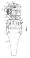
- FIG. 5is a partial cross-sectional view of the base of a blower/vacuum
- FIG. 6is an embodiment of a fan member
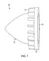
- FIG. 7is an embodiment of a diffuser
- FIG. 8is an embodiment of a vacuum assembly
- FIG. 9is an embodiment of a dedicated blower
- FIG. 10is an embodiment of a dedicated vacuum
- FIG. 11Ais a perspective view of an embodiment of a fan member with a first fan
- FIG. 11Bis a front view of the fan member shown in FIG. 11A ;
- FIG. 11Cis a side view of the fan member shown in FIG. 11A .
- FIGS. 1-3an exemplary embodiment of a combination of a blower and a vacuum, or a blower/vacuum 10 , for use in lawn care and maintenance.
- the blower/vacuum 10is configured to be used as both a blower 10 a ( FIG. 1 ) in a blower operation and configuration to blow leaves or other debris when in one configuration and a vacuum 10 b ( FIG. 2 ) in a vacuum operation and configuration for collecting and mulching leaves, grass, and other yard debris.
- the blower/vacuum 10is switchable by an operator between the blower configuration 10 a and the vacuum configuration 10 b .
- the blower 10 a and vacuum 10 butilize the same base 12 , and the removably attachable end that is connected to the base 12 determines the configuration and operation of the blower/vacuum 10 .
- an exemplary embodiment of the base 12includes a housing 14 , a graspable handle 16 , a user-controlled trigger 18 , a starter assembly 20 , a power source 22 positioned within the housing 14 , a shield 24 , and an attachment shell 30 .
- the power source 22may also be an engine having a push-button start, an electric motor powered by a rechargeable battery, a replaceable battery, an A/C-powered electric motor, or any other power source capable of providing sufficient power to operate the handheld tool.
- the housing 14 and handle 16are integrally formed or molded as a single piece. In another embodiment, the housing 14 and handle 16 are formed separately and attached to each other by way of a mechanical fastener or the like. In an embodiment, the handle 16 is configured to be fixedly positioned relative to the housing 14 . In another embodiment, the handle 16 is movable relative to the housing 14 to allow the operator to ergonomically position the handle 16 relative to the housing 14 to maximize comfort while carrying the blower/vacuum 10 .
- the user-controlled trigger 18is operatively connected to the handle 16 and controls the speed of the blower/vacuum 10 .
- the starter assembly 20is operatively connected to the side of the housing 16 , as shown in FIG. 1 . It should be understood by one having ordinary skill in the art that the starter assembly 20 can extend from either side of the housing or the rear of the housing, depending upon the orientation and type of the power source 22 . In the illustrated exemplary embodiment, the starter assembly 20 is a pull-start having a handle attached to a wound rope (not shown). It should be understood by one having ordinary skill in the art that the starter assembly 20 can be formed as a different mechanical operable system for starting the power source (such as a crank, or the like) or an electrical system capable of starting the power source (such as a push-button starter, or the like).
- the housing 14is configured to protect the power source 22 ( FIG. 5 ), or other power source, located therewithin.
- the housing 14can be formed of a plurality of pieces, which allows the power source 22 to be operatively connected to the housing 14 and be disposed therein when the housing 14 is assembled.
- the shield 24extends forwardly from the housing 14 , wherein the shield 24 is configured to protect the drive shaft 26 ( FIG. 5 ) that extends from the power source 22 to the fan member 28 , as shown in FIGS. 1-3 .
- the shield 24can be formed separately from the housing 14 and attached thereto, or the shield 24 can be integrally formed with a portion of the housing 14 .
- the shield 24is a single member.
- the shield 24is formed of multiple pieces. At least a portion of the shield 24 is positioned within the attachment shell 30 .
- the attachment shell 30 of the base 12is formed as a generally conical shape that extends from the housing 14 and surrounds at least a portion of the shield 24 , as shown in FIGS. 1-3 .
- the attachment shell 30is configured to provide a structure to which the blower assembly 32 and the vacuum assembly 34 are removably and selectively attachable.
- the attachment shell 30is formed of a clear, or otherwise transparent material.
- the attachment shell 30is formed of clear polycarbonate, plastic, or any other materials providing sufficient strength and rigidity to withstand the pressure increases and decreases within the attachment shell 30 as well as withstand repeated contact with debris that is suctioned when in the vacuum configuration 10 b while also being transparent to allow an operator the ability to view into the attachment shell 30 to determine if there is a blockage or any other problem. It should be understood by one having ordinary skill in the art that the attachment shell 30 may also be formed of a non-clear or a non-transparent material. The attachment shell 30 surrounds at least a portion of the fan member 28 .
- the mixed-flow fan member 28is operatively connected to the base 12 and is powered by the power source 22 by way of a drive shaft 26 .
- the drive shaft 26is configured to rotate in the same direction during both the blower configuration as well as the vacuum configuration, and the fan member 28 is configured to provide positive-pressure air flow when the blower assembly 32 is attached to the attachment shell 30 and a reduced-pressure air flow when the vacuum assembly 34 is attached to the attachment shell 30 .
- the mixed-flow fan member 28is formed as a one-piece member, as shown in FIG. 6 , of molded plastic but can be formed of any material.
- the fan member 28includes a rear end 36 , a forward end 38 , central hub 40 , a plate 42 extending radially from the central hub 40 , a first fan 44 having a plurality of first fan blades 46 extending radially from the central hub 40 , and a second fan 48 having a plurality of second fan blades 50 extending radially from the central hub 40 .
- the fan member 28is includes a first fan 44 formed separately from the second fan 48 , wherein the first and second fans 44 , 48 are attached to each other to form the fan member 28 .
- the fan member 28does not include the plate 42 separating the first and second fans 44 , 48 .
- the hub 40is a cylindrical member aligned axially with the drive shaft 26 , wherein the drive shaft 26 is received within the hub 40 to allow the fan member 28 to be releasably attached or otherwise connected to the drive shaft 26 .
- the drive shaft 26is configured to drive, or rotate, the fan member 28 about the axis formed by the draft shaft 26 .
- the fan member 28is formed as a single component in which each of the portions of the fan member 28 are integrally formed together.
- the fan member 28is formed of molded plastic or other resilient material that may include aluminum, titanium, high density polyethylene (HDPE), or any other resilient material.
- Fans used for generating air floware typically formed as an axial fan or a centrifugal fan.
- Axial fansare configured to have a plurality of fan blades extending substantially radially from a hub, wherein the radial fan blades generate air flow that is aligned, or parallel to the drive shaft to which the fan is attached. In other words, the axial fan pushes the air along from upstream to downstream along a linear-like pathway.
- the fan blades of the axial fanare typically arranged in a cantilever arrangement such that the base of the blade is attached to a hub and the tips of the blade are unconstrained.
- Axial fansare often used in wind turbines, box/home fans, fume extraction, winnowing, and the like.
- Centrifugal fansare configured to have a plurality of fan blades attached to the outer circumferential surface of a central hub, wherein the fan blades extend radially outward from the hub. Upstream air is drawn toward the central hub of the centrifugal fan, wherein the fan blades are aligned and oriented to push the air radially outward in a centrifugal manner.
- the blades of the centrifugal fanare typically positioned against a plate (or between a pair of parallel plates) that likewise extends from the central hub, wherein the plate prevents axial movement of the air flow, thereby generally confining the air flow to radial flow.
- Centrifugal fansare often used in handheld lawn care blowers, HVAC systems, and the like where the desired air flow is radially outward from the fan.
- the fan member 28 used in the blower/vacuumincorporates aspects of both axial and centrifugal fans to provide a mixed-flow fan, wherein the generated air flow is both radial and axial.
- the plate 42is formed as a substantially circular and planar member that extends radially from the outer circumference of the central hub 40 , wherein the plate 42 is positioned about midway between the rear end 36 and the forward end 38 of the fan member 28 .
- the plate 42is configured to separate the first fan 44 from the second fan 48 , thereby providing two distinct operations of the fan member 28 —one for blowing and the other for vacuuming, as will be explained below.
- the first and second fan blades 46 , 50have substantially the same width relative to the longitudinal axis of the fan member 28 between the rear and forward ends 36 , 38 thereof.
- the plate 42is positioned longitudinally closer to either the rear end 36 or the forward end 38 of the fan member 28 , thereby allowing either the first or second fan blades 46 , 50 to have a larger width than the other set of fan blades.
- the first fan 44is configured as an axial fan in which the first fan blades 46 are operatively connected to the central hub 40 , extending radially outward beyond the circumferential outer edge of the plate 42 in a cantilevered manner.
- the first fan blades 46are angled or curved relative to the central hub 40 .
- the first fan blades 46are both angled along the circumference of the hub 40 but also curved between the base (intersecting with the hub 40 ) and the tip (radially outward edge) of each blade.
- the base of each of the first fan blades 46is angled such that the base is radially closer to the drive shaft 26 near the rear end 36 and radially further away from the drive shaft 26 near the plate 42 .
- the outer circumferential edge of the first fan blades 46is also formed at an angle between the plate 42 and the rear end 36 .
- the base of each of the first fan blades 46is aligned with the longitudinal axis A, and the first fan blades 46 extend in a substantially planar manner between the base and tip of each blade.
- the first fan blades 46can be planar, curved, a combination thereof, or have any shape sufficient to provide increased air flow resulting from the rotation of the fan member 28 , wherein the air flow generated by the first fan blades is substantially parallel to the drive shaft 26 ( FIG. 5 ).
- the first fan blades 46extend from a frustoconical surface operatively connected to the central hub 40 , wherein the radial distance between the frustoconical surface and the central hub 40 increases as it extends away from the rear end 36 toward the plate 42 .
- the second fan 48is formed as a centrifugal fan.
- the second fan 48is formed of a plurality of second fan blades 50 that are positioned between the plate 42 and the forward end 38 .
- the second fan blades 50extend from the central hub 40 in a substantially planar manner, wherein the blade tip of each of the second fan blades 50 is aligned with the longitudinal axis A and substantially aligned with the outer circumference of the plate 42 , but it should be understood by one having ordinary skill in the art that tips of the second fan blades 50 may extend beyond the outer circumferential edge of the plate 42 .
- the second fan blades 50are curved, similar to the curved first fan blades 46 described above. In the illustrated embodiment, the first fan blades 46 extend radially outward a greater distance than the second fan blades 50 .
- the first fan 44 and the second fan 48 of the fan member 28are configured to perform separate operations, depending upon the configuration of the blower/vacuum 10 and the mode of the fan member 28 .
- the blower/vacuum 10is in the blower configuration 10 a ( FIG. 1 ).
- the fan member 28is in the blower mode in which the first fan 44 is active and the second fan 46 is inactive but continues to rotate in conjunction with the first fan 44 .
- the first fan 44is configured to provide positive-pressure air flow to cause air to be blown axially through the blower assembly 32 .
- the blower/vacuum 10is in the vacuum configuration 10 b ( FIG. 2 ).
- the fan member 28is in the vacuum mode in which the second fan 46 is active and the first fan 44 is inactive but continues to rotate in conjunction with the second fan 46 .
- the second fan 48is configured to provide negative-pressure air flow to cause air to be drawn toward the base 12 into and through the vacuum assembly 34 due to the centrifugal air flow from the second fan 46 .
- the fan member 28is configured to blow air through an outlet port.
- blower configuration 10 athe air flow from the fan member 28 exits through the blower tube 62 which acts as the outlet port, as explained below; in the vacuum configuration 10 b, the air flow from the fan member 28 exits through the outlet 102 of the fan housing 104 which acts as the outlet port, as explained below.
- the switchability between the blower and vacuum configurations 10 a, 10 b, as illustrated in FIG. 4causes each of the first and second fans 44 , 48 to be utilized separately for different configurations of the blower/vacuum 10 .
- an embodiment of the blower assembly 32includes a diffuser 60 , a blower housing 62 , a blower tube 64 , and an optional extension tube 66 .
- the blower assembly 32is releasably attachable to the base 12 to generate the blower configuration 10 a ( FIG. 1 ).
- the diffuser 60includes an elongated cone 70 having an open end 72 , a platform 74 surrounding and extending radially outward from the open end 72 , and a plurality of vanes 76 extending from the platform 74 adjacent to the outer circumferential surface of the cone 70 , as illustrated in FIG. 7 .
- the cone 70is an elongated, substantially hollow member, wherein the open end 72 is positioned upstream, or otherwise directed toward the base 12 .
- the tip of the cone 70extends away from the open end 72 and the base 12 , wherein the diameter of the cone 70 narrows as the cone 70 extends away from the open end 72 .
- the open end 72forms a substantially circular opening to the inside of the cone 70 .
- the open end 72is configured to receive and completely surround the second fan 48 of the fan member 28 .
- the platform 74is formed of an annular ring and a plurality of ribs, wherein the annular ring is operatively connected to the outer surface of the cone 70 by way of the plurality of ribs.
- the ribsform open pathways between the annular ring and the cone 70 to allow air to flow from the fan member 28 and past the diffuser 60 between the annular ring of the platform 74 and the cone 70 , as shown in FIG. 7 .
- the air flow through the platform 74 between the annular ring and the cone 70is generated by the first fan 44 of the fan member 28 .
- the vanes 76are extensions of the ribs of the platform 74 such that the vanes 76 and the ribs are aligned to provide a continuous wall or barrier for directing the air flow over the outer surface of the cone 70 .
- the vanes 76are spaced apart from the ribs of the platform 74 in order to form separate barriers for directing the air flow over the outer surface of the cone 70 separate from the ribs that provide pathways through which air can pass through the platform 74 .
- the vanes 76can be formed as planar members or curved members for directing the flow of air past the outer surface of the cone 70 , but it should be understood by one having ordinary skill in the art that the overall shape, configuration, and placement of the vanes 76 is optimized to maximize performance of the blower/vacuum 10 when in the blower configuration 10 a.
- the blower housing 62 of the blower assembly 32is attachable to the attachment shell 30 of the base 12 to operatively connect the blower assembly 32 to the base 12 , as shown in FIGS. 3-5 .
- the blower housing 62is a clear, or otherwise substantially transparent, member configured to receive and surround the diffuser 60 .
- the blower housing 62provides a flow path with a narrowing diameter to aide in increasing the velocity of the air as it flows over the diffuser 60 .
- the blower housing 62includes a ridge 80 formed on the inner surface thereof, wherein the diffuser 60 is configured to abut the ridge 80 when the blower housing 62 is attached to the attachment shell 30 .
- the ridge 80provides positive positioning of the diffuser 60 relative to the fan member 28 when the blower assembly 32 is attached to the base 12 .
- FIG. 3illustrates an exemplary embodiment of a mechanical attachment mechanism 82 , which includes an anchor 84 integrally formed with both the blower housing 62 and the attachment shell 30 .
- the anchor 84is formed generally as a hook that extends away from the opposing member to which it is being attached.
- the attachment mechanism 82also includes a toggle 86 , which is secured to one of the anchors 84 and is configured to releasably engage the anchor 84 on the opposing member.
- the toggle 86is secured to the anchor 84 of the blower housing 62 by way of a pin that provides an axis of rotation for the toggle 86 , and the toggle 86 is configured to releasably engage the anchor 84 on the attachment shell 30 .
- the toggle 86is secured to the anchor 84 of the attachment shell 30 with the pin and is configured to releasably engage the anchor 84 of the blower housing 62 .
- one embodiment of the attachment shell 32 and blower housing 62may include two, three, or more anchor-toggle-anchor attachment mechanisms 82 positioned about the periphery to attach these members together.
- an anchor-toggle-anchor attachment mechanism 82may be used in conjunction with a hook-and-loop attachment mechanism 82 , wherein the hook-and-loop (not shown) includes a loop extending from the attachment shell 32 and a hook extending from the blower housing 62 such that the hook is received in the loop to form a hinge or rotatable connection between the blower housing 62 and the attachment shell 32 which allows the blower housing 62 to be positively secured and rotatable with the hook-and-loop attachment mechanism while the anchor-toggle-anchor attachment mechanism is secured at the opposite edge between the members.
- the hook-and-loopincludes a loop extending from the attachment shell 32 and a hook extending from the blower housing 62 such that the hook is received in the loop to form a hinge or rotatable connection between the blower housing 62 and the attachment shell 32 which allows the blower housing 62 to be positively secured and rotatable with the hook-and-loop attachment mechanism while the anchor-toggle-anchor attachment
- another attachment mechanism 82 for securing the blower housing 62 to the attachment shell 30is a threaded engagement (not shown) in which both the blower housing 62 and the attachment shell 30 include threads which are configured to mesh with the threads of the opposing member which allow the blower housing 62 to be twisted relative to the attachment shell 30 such that the threads mesh and provide a positive releasable engagement therebetween.
- the attachment mechanism(s) 82 between the blower housing 62 and the attachment shell 30include a plurality of bolts (not shown) that allow the blower housing 62 to be releasably attachable to the attachment shell 30 .
- attachment mechanisms 82While these exemplary embodiments of attachment mechanisms 82 are mechanical, the attachment mechanisms 82 can also be formed as magnets that provide releasable engagement between the blower housing 62 and the attachment shell 30 . It should be understood by one having ordinary skill in the art that any attachment mechanism 82 , or a plurality of the same or different attachment mechanisms, can be used to provide for releasable attachment between the blower housing 62 and the attachment shell 30 .
- the blower tube 64 of the blower assembly 32is releasably attachable to the end of the blower housing 62 opposite the end attachable to the attachment shell 30 , as shown in FIGS. 1, 3, and 4-5 .
- the blower tube 64is an elongated tube having an inlet and an outlet, wherein the diameter of the inlet is larger than the diameter of the outlet. This reduced diameter acts to increase the velocity of the air flow through the blower tube 64 .
- the blower tube 64is releasably securable to the blower housing 62 by way of at least one attachment mechanism (not shown), such as a keyed locking mechanism or the like.
- the blower tube 64is releasably securable to the blower housing 62 by way of a friction fit.
- the blower assembly 32includes an extension tube 66 that is attachable to the blower tube 64 .
- the extension tube 66is configured to extend the length of the blower tube 64 to allow the operator to remain standing upright yet position the end of the blower assembly 32 as close to the ground or surface being blown without the need to bend over to achieve such positioning.
- the length of the extension tube 66can vary depending upon the height of the operator or the operation in which the blower configuration 10 a is being used.
- the blower assembly 32is attached to the base 12 by way of at least one attachment mechanism 82 , as shown in FIGS. 1, 3, and 5 .
- the diffuser 60is abutting the ridge 80 formed on the inner surface of the blower housing 62 , and the diffuser 60 is positively positioned relative to the fan member 28 such that the second fan 48 is inserted through the open end 72 and located within the cone 70 of the diffuser 60 .
- the platform 74is either abutting the plate 42 of the fan member 28 that separates the first and second fans 44 , 48 or is positioned immediately adjacent to the plate 42 .
- the diffuser 60contacts the plate 42 of the fan member 28 . In another embodiment, the diffuser 60 is spaced very slightly apart from the plate of the fan member 28 .
- the positioning of the diffuser relative to the fan member 28 , wherein the second fan 48 is located within the cone 70 of the diffuser 70leaves only the first fan blades 46 exposed to generate a positive-pressure air flow directed over the diffuser 60 while simultaneously deactivating the effect of the second fan 48 as any air movement generated by the second fan 48 is contained within the cone 70 of the diffuser 60 .
- the diffuser 60effectively “hides” the second fan blades 50 to allow only the first fan blades 46 to be active in the blower configuration 10 a, but the second fan 48 continues to rotate simultaneously with the first fan 44 .
- the throttle 18 of the base 12controls the output rotational speed from the power source 22 that rotates the drive shaft 26 which, in turn, rotates the fan member 28 .
- rotation of the first fan 44generates a positive-pressure air flow directed over the diffuser 69 , through the blower housing 62 , blower tube 64 , and then through the optional extension tube 66 , if present.
- the rotational output of the power source 22is increased in response to the throttle 18 , the velocity of the air flow through the blower assembly 32 increases, and vice-versa with respect to the velocity of the air flow.
- the blower assembly 32is removable from the base 12 and replaceable with the vacuum assembly 34 , and vice-versa, to switch the blower/vacuum 10 from the blower configuration 10 a ( FIG. 1 ) to the vacuum configuration ( FIG. 2 ). Similar to the blower assembly 32 is releasably attachable to the attachment shell 30 of the base 12 using at least one attachment mechanism 82 for positively securing the vacuum assembly 34 .
- the vacuum assembly 34includes a first vacuum shell 90 and a second vacuum shell 92 which together form a vacuum housing 98 , a vacuum tube 94 , and an optional collection bag 96 .
- the first and second vacuum shells 90 , 92 of the vacuum assembly 34are formed as substantially mirror images of each other and are attachable together to form a vacuum housing 98 , as shown in FIGS. 2-3 and 8 .
- the vacuum housing 98includes an inlet 100 , an outlet 102 , a fan housing 104 , and an optional handle 106 .
- the first and second vacuum shells 90 , 92include a plurality of bosses to allow the opposing shells to be connected together with nuts and bolt.
- the first and second vacuum shells 90 , 92can be connected together using any attachment mechanism that allows the shells to be releasably attachable.
- the vacuum housing 98is formed of separate pieces.
- the vacuum housing 98is formed as a single integral member.
- the fan housing 104 of the vacuum housing 98is fluidly connected to both the inlet 100 and the outlet 102 , thereby providing a continuous pathway between the inlet 100 and outlet 102 and through the fan housing 104 , as shown in FIGS. 2-3 and 8 .
- the fan housing 104has a toroid-like shape without the inner diameter surface, thus providing a vertically-aligned forward wall 110 , a rear wall 112 oriented parallel relative to the forward wall 110 , and an annular wall 114 extending between the forward wall 110 and the rear wall 112 .
- the forward wall 110includes an opening from which the inlet 100 extends in a forward direction.
- the rear wall 112likewise includes a circular opening.
- the outlet 102extends in a downward direction from the annular wall 114 , in a substantially perpendicular manner relative to the inlet 100 , from the fan housing 104 .
- the toroidal fan housing 104is configured to receive a portion of the fan member 28 through the opening in the rear wall 112 when the vacuum housing 98 is operatively connected to the base 12 .
- the vacuum housing 98is attachable to the base 12 in a similar manner as the blower housing 62 , in particular, by way of at least one attachment mechanism 82 , described above.
- the same attachment mechanism 82should be used to attach the vacuum housing 98 to the base 12 as used to attach the blower housing 62 to the base 12 .
- the illustrated exemplary embodimentutilizes at plurality of anchor-toggle-anchor attachment mechanisms to attach the vacuum assembly 24 to the attachment shell 30 of the base 12 , but it should be understood by one having ordinary skill in the art that any other attachment mechanism(s) can be used.
- the vacuum tube 94 of the vacuum assembly 34is attachable to the vacuum housing 98 to provide an extension for the suction inlet 100 to be located closer to the ground or other structure so as to reduce or eliminate the need for the operator to continually bend over in order to use the vacuum/blower 10 in the vacuum configuration 10 b.
- the vacuum tube 94is an elongated tubular member which can be formed as a straight tube ( FIG. 2 ) or a tube having at angled portion ( FIG. 3 ).
- the vacuum tube 94is configured to be attached to the inlet 100 that extends forwardly from the fan housing 104 .
- the vacuum tube 94is attached to the inlet 100 by friction fit in which the inner diameter of the vacuum tube 94 is the same or just slight larger diameter than the outer diameter of the inlet 100 such that the vacuum tube 94 is slid over the inlet 100 for installation.
- the vacuum tube 94is attached to the inlet 100 by way of at least one attachment mechanism, which can be either the same type or a different type than used to attach the vacuum housing 98 to the base 12 .
- the vacuum housing 98includes an optional handle 106 (included— FIG. 8 ; not included— FIG. 2 ), wherein the handle 106 extends upwardly from the fan housing 104 .
- the handle 106allows the user to use both hands to grasp the blower/vacuum 10 , wherein one hand can grasp the handle 16 of the base and the other hand can grasp the handle 106 of the vacuum housing 98 .
- the entire handle 106can be integrally formed with one of the first or second vacuum shells 90 , 92 , or half of the handle 106 can be integrally formed with a respective vacuum shell 90 , 92 such that when the first and second vacuum shells 90 , 92 are attached to each other, the handle halves form a complete handle 106 .
- the vacuum assembly 34further includes an optional collection bag 96 , which is attachable to the outlet 102 of the vacuum housing 98 , as shown in FIGS. 2 and 4 .
- the collection bag 96includes a port that is configured to engage the outlet 102 by a friction fit.
- the collection bag 96includes a strap that can be positioned over the shoulder of the operator, which allows the weight of the debris in the collection bag 96 to be carried by the operator's body as opposed to having the entire weight added to the blower/vacuum 10 being carried.
- assembly of the blower/vacuum 10 in the vacuum configuration 10 bincludes attaching the first and second vacuum shells 90 , 92 together to form the vacuum housing 98 .
- the vacuum housing 98is then attached to the attachment shell 30 of the base 12 using a plurality of attachment mechanisms 82 which connect opposing anchors 84 located on both the attachment shell 30 and the vacuum housing 98 .
- the fan assembly 28is inserted into the opening in the rear wall 112 of the fan housing 104 such that the second fan 48 is positioned within the fan housing 104 and the rear wall 112 is abutting or positioned immediately adjacent to the plate 42 of the fan member 28 .
- the first fan 44is effectively deactivated as air flow caused by rotation of the first fan blades 46 is blocked by the rear wall 112 of the fan housing 104 .
- the second fan blades 50 of the second fan 48are active in the vacuum configuration 10 b.
- the vacuum tube 94 and collection bag 96can then be attached to the vacuum housing 98 .
- the throttle 18 of the base 12controls the output rotational speed from the power source 22 that rotates the drive shaft 26 which, in turn, rotates the fan member 28 .
- rotation of the second fan 48generates a negative-pressure air flow which creates a suction with draws air into the fan housing 104 through the inlet 100 (via the vacuum tube 94 ).
- the air flow and any debris that is drawn into the fan housing 104are then ejected out through the outlet 102 via centrifugal air flow generated by the second fan 48 of the fan member 28 .
- the rotation of the second fan 48acts to crush, pulverize, or otherwise break up at least some of the debris into smaller particles.
- the rotational output of the power source 22is increased in response to the throttle 18 , the velocity of the air flow through the vacuum assembly 34 increases, and vice-versa with respect to the velocity of the air flow.
- the exemplary embodiment of the combined blower/vacuum 10 described aboveutilizes a single fan member 28 that integrates both a first fan 44 and a second fan 48 , wherein each fan is configured to generate either a positive-pressure or negative-pressure air flow.
- the blower/vacuum 10is adapted to receive a blower assembly 32 that covers or hides the second fan 48 in a blower configuration 10 a to effectively deactivate the second fan 48 which allows the first fan 44 to generate the positive-pressure air flow through the blower assembly 32 .
- the blower/vacuum 10is also adapted to receive a vacuum assembly 34 that covers or otherwise hides the first fan 44 in a vacuum configuration 10 b to effectively deactivate the first fan 44 which allows the second fan 48 to generate the negative-pressure air flow through the vacuum assembly 34 .
- the fan member 28In the blower and vacuum configurations, the fan member 28 generates different types of air flow: axial air flow in the blower configuration and centrifugal air flow in the vacuum configuration. These two separate air flows generated by the same fan member 28 make the fan member 28 a mixed-flow fan, thereby allowing a single fan member 28 to be used in two completely distinct operations in different configurations.
- the blower/vacuum 10when in the blower configuration 10 a as shown in FIG. 5 , includes a power source 22 that is configured to super-charge the velocity of air flow being expelled from the blower assembly 32 .
- the power source 22includes a rearwardly-directed flywheel 120 that is positioned adjacent to the starter assembly 20 at the rear of the base 12 . As air is drawing into the housing 14 through rear vents 122 , the flywheel 120 directs the air over the engine components for cooling and then into the blower intake area.
- the flywheel 120includes a combination of fan vanes as well as a pair of oppositely-opposed magnets, wherein the magnets are configured to act in combination with an ignition module that generates a spark for the combustion cylinder.
- the air from the flywheel 120 that is forced over the power source 22is mixed and added to the air drawn into the blower intake area through the side vents 124 that are positioned between the power source 22 and the fan member 28 .
- the forced air from the flywheel 120results in increased air flow velocity produced by the first fan 44 in the blower configuration 10 a, thereby generating a super-charged, or increased air flow.
- the fan member 28produces enough suction of air from the housing 14 to cool the engine components without the flywheel 120 , but the flywheel 120 provides more efficient and more powerful blowing when a flywheel 120 is used.
- the flywheel 120 positioned at the rear of the base 12 for generating cooling airflow over the enginealso improves the performance of the engine as compared to the performance of the engine relying solely upon the fan member 28 creating air flow over the engine or the flywheel positioned at the front of the engine (between the engine and the fan member 28 ).
- the combined blower and vacuum 10is either a dedicated blower 110 ( FIG. 9 ) or a dedicated vacuum 210 ( FIG. 10 ), wherein the dedicated blower 110 and dedicated vacuum 210 are not interchangeable between operations or configurations.
- the dedicated blower 110includes substantially the same components as the blower/vacuum 10 , such as a base 112 , a drive shaft (not shown), an attachment shell 130 , a fan member 128 , and blower assembly 132 .
- the fan member 128 of the dedicated blower 110includes only the first fan 144 but not the second fan 48 ( FIG. 6 ), because the second fan 48 would never be utilized in the dedicated blower 110 .
- the first fan 144 of the dedicated blower 110is a mixed-flow fan.
- the fan member 128may also be formed to include both the first fan 144 as well as the second fan 48 .
- the blower assembly 132 of the dedicated blower 110remains removably attachable to the attachment shell 130 to allow the user to access the fan member 128 and other components for cleaning and general maintenance.
- FIGS. 11A-11Cillustrate an embodiment of the fan member 128 for a dedicated blower 110 .
- the illustrated embodiment of the fan member 128includes only the first fan 144 , but it should be understood by one having ordinary skill in the art that a fan member 128 having both the first and second fan 144 , 48 can be used.
- the first fan 144is configured as a mixed-flow fan in which the first fan blades 146 extend radially outward from the base 140 , wherein the first fan blades 146 extend outwardly beyond the circumferential outer edge of the frustoconical surface 141 in a cantilevered manner.
- the first fan blades 146are angled or curved relative to the central hub 140 .
- the first fan blades 146do not extend radially outward from the central hub 140 in a linear manner. As the first fan blades 146 extend from the central hub 140 , the first fan blades 146 continually curve. In one embodiment, the curvature of the first fan blades 146 is in the direction of rotation when the fan member 128 is rotated. In another embodiment, the curvature of the first fan blades 146 is in the opposite direction of rotation when the fan member 128 is rotated. In addition to the curvature of the first fan blades 146 in the radial direction, the first fan blades 146 are also angled with respect to the frustoconical surface 141 .
- first fan blades 146can be planar, curved, a combination thereof, or have any shape sufficient to provide increased air flow resulting from the rotation of the fan member 128 , wherein the air flow generated by the first fan blades 146 is substantially parallel to the drive shaft 26 ( FIG. 5 ).
- the dedicated vacuum 210includes substantially the same components as the blower/vacuum 10 , such as a base 212 , a drive shaft (not shown), an attachment shell 230 , and a vacuum assembly 234 .
- the fan member 228 of the dedicated vacuum 210includes only the second fan 248 but not the first fan 44 ( FIG. 6 ), because the first fan 44 would never be utilized in the dedicated vacuum 210 .
- the fan member 228may also be formed to include both the first fan 44 as well as the second fan 248 .
- the vacuum assembly 234 of the dedicated vacuum 210remains removably attached to the attachment shell 230 to allow the user to access the fan member 228 and other components for cleaning and general maintenance.
Landscapes
- Life Sciences & Earth Sciences (AREA)
- Environmental Sciences (AREA)
- Structures Of Non-Positive Displacement Pumps (AREA)
- Jet Pumps And Other Pumps (AREA)
Abstract
Description
Claims (14)
Priority Applications (2)
| Application Number | Priority Date | Filing Date | Title |
|---|---|---|---|
| US15/609,582US10674681B2 (en) | 2014-12-09 | 2017-05-31 | Blower/vacuum |
| US16/458,572US11246271B2 (en) | 2014-12-09 | 2019-07-01 | Blower/vacuum |
Applications Claiming Priority (3)
| Application Number | Priority Date | Filing Date | Title |
|---|---|---|---|
| US201462089572P | 2014-12-09 | 2014-12-09 | |
| US14/962,687US10375901B2 (en) | 2014-12-09 | 2015-12-08 | Blower/vacuum |
| US15/609,582US10674681B2 (en) | 2014-12-09 | 2017-05-31 | Blower/vacuum |
Related Parent Applications (1)
| Application Number | Title | Priority Date | Filing Date |
|---|---|---|---|
| US14/962,687ContinuationUS10375901B2 (en) | 2014-12-09 | 2015-12-08 | Blower/vacuum |
Related Child Applications (1)
| Application Number | Title | Priority Date | Filing Date |
|---|---|---|---|
| US16/458,572ContinuationUS11246271B2 (en) | 2014-12-09 | 2019-07-01 | Blower/vacuum |
Publications (2)
| Publication Number | Publication Date |
|---|---|
| US20170258013A1 US20170258013A1 (en) | 2017-09-14 |
| US10674681B2true US10674681B2 (en) | 2020-06-09 |
Family
ID=56093141
Family Applications (3)
| Application Number | Title | Priority Date | Filing Date |
|---|---|---|---|
| US14/962,687Active2037-07-22US10375901B2 (en) | 2014-12-09 | 2015-12-08 | Blower/vacuum |
| US15/609,582Active2036-11-26US10674681B2 (en) | 2014-12-09 | 2017-05-31 | Blower/vacuum |
| US16/458,572Active2037-01-10US11246271B2 (en) | 2014-12-09 | 2019-07-01 | Blower/vacuum |
Family Applications Before (1)
| Application Number | Title | Priority Date | Filing Date |
|---|---|---|---|
| US14/962,687Active2037-07-22US10375901B2 (en) | 2014-12-09 | 2015-12-08 | Blower/vacuum |
Family Applications After (1)
| Application Number | Title | Priority Date | Filing Date |
|---|---|---|---|
| US16/458,572Active2037-01-10US11246271B2 (en) | 2014-12-09 | 2019-07-01 | Blower/vacuum |
Country Status (1)
| Country | Link |
|---|---|
| US (3) | US10375901B2 (en) |
Cited By (3)
| Publication number | Priority date | Publication date | Assignee | Title |
|---|---|---|---|---|
| US12215716B2 (en) | 2023-03-29 | 2025-02-04 | Milwaukee Electric Tool Corporation | Blower |
| US12352274B2 (en) | 2022-03-21 | 2025-07-08 | Milwaukee Electric Tool Corporation | Axial blower |
| US12385494B2 (en) | 2021-10-11 | 2025-08-12 | Milwaukee Electric Tool Corporation | Fan for handheld blower |
Families Citing this family (15)
| Publication number | Priority date | Publication date | Assignee | Title |
|---|---|---|---|---|
| US20160235011A1 (en)* | 2015-02-12 | 2016-08-18 | Joseph Malik Glisson | System and device for yard waste collection |
| JP6710070B2 (en)* | 2016-03-14 | 2020-06-17 | 東芝ライフスタイル株式会社 | Handheld vacuum cleaner |
| US10292559B2 (en)* | 2016-04-15 | 2019-05-21 | Transform Sr Brands Llc | Ergonomic gripping mechanisms of a handheld air movement apparatus |
| USD949315S1 (en)* | 2016-06-24 | 2022-04-19 | Ebm-Papst Mulfingen Gmbh & Co. Kg | Vane damper with trailing edge |
| US10897858B2 (en)* | 2017-11-30 | 2021-01-26 | Tti (Macao Commercial Offshore) Limited | Blower/mulcher |
| WO2019109278A1 (en)* | 2017-12-06 | 2019-06-13 | Husqvarna Ab | Blower with improved balance and construction |
| USD871184S1 (en) | 2017-12-06 | 2019-12-31 | Husqvarna Ab | Power head with tool attachment interface |
| JP7108443B2 (en)* | 2018-03-30 | 2022-07-28 | 株式会社マキタ | air blower |
| DE102018004680A1 (en)* | 2018-06-12 | 2019-12-12 | Andreas Stihl Ag & Co. Kg | blower |
| CN112303005B (en)* | 2019-08-02 | 2024-12-31 | 珠海格力电器股份有限公司 | Mixed flow fan blade, air duct structure and air conditioner indoor unit |
| US11812687B2 (en)* | 2019-12-27 | 2023-11-14 | Ash GILPIN | Leaf mulcher |
| USD1077859S1 (en) | 2020-11-17 | 2025-06-03 | Milwaukee Electric Tool Corporation | Blower |
| WO2022147300A1 (en) | 2020-12-30 | 2022-07-07 | Milwaukee Electric Tool Corporation | Handheld blower |
| US20220395151A1 (en)* | 2021-06-14 | 2022-12-15 | Sharon Elizabeth Phillip | Modular household blower system |
| JP7672291B2 (en)* | 2021-06-25 | 2025-05-07 | 株式会社やまびこ | Axial Flow Blower |
Citations (290)
| Publication number | Priority date | Publication date | Assignee | Title |
|---|---|---|---|---|
| US4076460A (en) | 1972-11-30 | 1978-02-28 | Roof Earl O | Convertible lawn care apparatus |
| US4090813A (en) | 1975-05-14 | 1978-05-23 | Hitachi, Ltd. | High-efficiency turbo-machine impellers |
| US4152094A (en) | 1975-10-31 | 1979-05-01 | Hitachi, Ltd. | Axial fan |
| US4231706A (en) | 1977-04-27 | 1980-11-04 | Hitachi, Ltd. | Impeller of a centrifugal blower |
| US4412781A (en) | 1980-07-21 | 1983-11-01 | Hitachi Ltd. | Vortex blower |
| US4432694A (en) | 1980-02-25 | 1984-02-21 | Hitachi, Ltd. | Blower |
| EP0198654A1 (en) | 1985-04-08 | 1986-10-22 | McCULLOCH CORPORATION | Blower/vacuum device |
| US4647271A (en) | 1984-06-08 | 1987-03-03 | Hitachi, Ltd. | Impeller of centrifugal blower |
| US4718140A (en) | 1986-03-10 | 1988-01-12 | Henry Johnson | Fireplace blower and vacuum |
| US4767285A (en) | 1986-04-14 | 1988-08-30 | Hitachi, Ltd. | Electric blower |
| US4829625A (en) | 1987-10-23 | 1989-05-16 | Wang Ta C | Portable vacuum cleaner/air compressor with light |
| USRE33050E (en)* | 1985-12-03 | 1989-09-12 | White Consolidated Industries, Inc. | Hand held gas engine blower |
| US5035586A (en) | 1989-04-19 | 1991-07-30 | White Consolidated Industries, Inc. | Portable hand-held blower/vacuum unit with resilient engine mounting system |
| US5233946A (en) | 1991-09-19 | 1993-08-10 | Kioritz Corporation | Engine-driven blower unit |
| US5267371A (en) | 1992-02-19 | 1993-12-07 | Iona Appliances Inc. | Cyclonic back-pack vacuum cleaner |
| US5269665A (en)* | 1989-04-19 | 1993-12-14 | White Consolidated Industries, Inc. | Portable hand-held blower/vacuum unit with resilient engine mounting system |
| US5281083A (en) | 1991-06-18 | 1994-01-25 | Hitachi, Ltd. | Vortex flow blower |
| US5395210A (en) | 1989-02-13 | 1995-03-07 | Hitachi, Ltd. | Vortex flow blower having blades each formed by curved surface and method of manufacturing the same |
| US5487639A (en) | 1993-02-23 | 1996-01-30 | Hitachi, Ltd. | Vortex flow blower and vane wheel therefor |
| US5533869A (en) | 1994-11-28 | 1996-07-09 | Homelite, Inc. | Power tool exhaust cooling system |
| US5569023A (en) | 1993-08-12 | 1996-10-29 | Hitachi, Ltd. | Vortex blower |
| US5588178A (en) | 1995-06-07 | 1996-12-31 | Mcculloch Corporation | Impeller for blower/vacuum |
| WO1997030620A1 (en) | 1996-02-21 | 1997-08-28 | Ryobi Ltd. | Blower and vacuum device |
| EP0792578A2 (en) | 1996-03-01 | 1997-09-03 | Valex S.r.L. | Portable blower-vacuum unit |
| US5709531A (en) | 1993-04-28 | 1998-01-20 | Hitachi, Ltd. | Centrifugal compressor and vaned diffuser |
| US5894630A (en) | 1996-03-15 | 1999-04-20 | International Retail Direct Promotions, Inc. | Air conducting convertor for string trimmer |
| US6116864A (en)* | 1997-01-15 | 2000-09-12 | Andreas Stihl Ag & Co. | Motor cooling means for a vacuum/blower device |
| US6141823A (en) | 1996-02-21 | 2000-11-07 | Ryobi Limited | Blower and vacuum device |
| US6146094A (en) | 1997-07-11 | 2000-11-14 | Hitachi, Ltd. | Motor-driven blower and method of manufacturing impeller for motor-driven blower |
| US20010008439A1 (en) | 1997-11-20 | 2001-07-19 | Hitachi, Ltd. | Liquid crystal projector, and projection lens unit, optical unit and cooling system for the same |
| US20010015194A1 (en) | 1998-06-22 | 2001-08-23 | Hitachi, Ltd. | Cylinder injection type internal combustion engine, control method for internal combustion engine, and fuel injection valve |
| US20010028241A1 (en) | 1995-02-21 | 2001-10-11 | Hitachi, Ltd. | Device and method for supplying power to a vehicle, semi-conductor circuit device for use in the same and collective wiring device for a vehicle or an automobile |
| US20010054847A1 (en) | 1996-06-13 | 2001-12-27 | Hitachi, Ltd. | Power supplying apparatus for a vehicle and an intensive wiring apparatus |
| US6368076B1 (en) | 1995-05-10 | 2002-04-09 | Martin Zoland | Air-flow modifying nozzle |
| US6386196B1 (en) | 2000-03-13 | 2002-05-14 | Steven E. Culton | Warning device for oxygen delivery system failure |
| US20020092508A1 (en) | 2001-01-16 | 2002-07-18 | Hitachi Ltd. | Heating device and engine drive method |
| US20020100791A1 (en) | 1999-12-10 | 2002-08-01 | Hitachi, Ltd. | Soldering machine |
| US20020112924A1 (en) | 2001-02-21 | 2002-08-22 | Hitachi Ltd. | Elevator |
| US20020113492A1 (en) | 1997-04-21 | 2002-08-22 | Hitachi, Ltd. | Electric power supply system for a vehicle |
| US6442790B1 (en) | 2001-02-09 | 2002-09-03 | The Toro Company | Portable blower/vacuum having air inlet cover attachable to blower tube |
| US20020122750A1 (en) | 1999-11-26 | 2002-09-05 | Hitachi, Ltd. | Apparatus for treating perfluorocompound gas |
| US20020131913A1 (en) | 2001-03-16 | 2002-09-19 | Hitachi, Ltd. | Method and apparatus for treating perfluorocompounds |
| US20020170432A1 (en) | 2001-03-19 | 2002-11-21 | Hmi Industries, Inc., A Delaware Corporation | Filter system |
| US6488475B2 (en) | 2000-03-30 | 2002-12-03 | Matsushita Electric Industrial Co., Ltd. | Electric blower and electric cleaner with an air cooled power device situated between the impeller and motor |
| US20030004391A1 (en) | 2001-04-03 | 2003-01-02 | Hitachi, Ltd. | Radioactive substance decontamination method and apparatus |
| US6503065B2 (en) | 1999-11-12 | 2003-01-07 | Tanaka Kogyo Co., Ltd. | Engine blower |
| US20030019585A1 (en) | 2001-07-19 | 2003-01-30 | Hitachi Kokusai Electric Inc. | Substrate processing apparatus and method for fabricating semiconductor device |
| US20030098211A1 (en) | 1996-02-21 | 2003-05-29 | Hitachi, Ltd. | Device and method for supplying power to a vehicle, semi-conductor circuit device for use in the same and collective wiring device for a vehicle or an automobile |
| US20030116352A1 (en) | 2001-12-21 | 2003-06-26 | Hitachi, Ltd. | Wave soldering method using lead-free solder, apparatus therefor, and wave-soldered assembly |
| US20030131895A1 (en) | 2001-04-06 | 2003-07-17 | Hitachi Plant Engineering & Construction Co., Ltd. | Changeover valve and gas transportation pipe system |
| US20030133761A1 (en) | 2001-09-03 | 2003-07-17 | Hitachi Plant Engineering & Construction Co., Ltd. | Gas transportation method for grain |
| US20030133760A1 (en) | 2002-01-14 | 2003-07-17 | Hitachi Plant Engineering & Construction Co., Ltd. | Gas transportation method for grain |
| US20030147769A1 (en) | 2000-08-28 | 2003-08-07 | Hitachi, Ltd. | Corrosion-resisting and wear-resisting alloy and device using the same |
| US20030172646A1 (en) | 2002-01-22 | 2003-09-18 | Hitachi, Ltd. And Hitachi Car Engineering Co., Ltd | Moisture removal device and method thereof for internal combustion engine use exhaust gas cleaning device |
| US6629818B2 (en) | 2001-02-09 | 2003-10-07 | The Toro Company | Impeller for use with portable blower/vacuums |
| US20030231898A1 (en) | 2002-06-14 | 2003-12-18 | Hitachi Printing Solutions, Ltd. | Film loader for an image forming apparatus |
| US20040032563A1 (en) | 2001-10-31 | 2004-02-19 | Hitachi, Ltd. | Method for manufacturing liquid crystal display panels |
| US20040065096A1 (en) | 2002-10-07 | 2004-04-08 | Hitachi Plant Engineering & Construction Co., Ltd. | Air-conditioning control apparatus using heater |
| US6735813B2 (en) | 2001-02-15 | 2004-05-18 | Ryobi, Ltd. | Mechanism for switching airflow mode of air blower/vacuum |
| US20040112119A1 (en) | 2002-12-13 | 2004-06-17 | Hitachi Unisia Automotive, Ltd. | Gas-tightness diagnosing apparatus for a fuel tank with an evaporative emission purge system |
| US20040165909A1 (en) | 2003-02-21 | 2004-08-26 | Hitachi Printing Solutions, Ltd. | Belt unit of electrophotographic printing apparatus |
| US20040211345A1 (en) | 2001-11-16 | 2004-10-28 | Hitachi, Ltd. | Solid fuel burner, burning method using the same, combustion apparatus and method of operating the combustion apparatus |
| US6873525B2 (en) | 2000-12-20 | 2005-03-29 | Hitachi, Ltd. | Liquid cooling system and personal computer using the same |
| US6874694B2 (en) | 2002-03-20 | 2005-04-05 | Hitachi, Ltd. | Heat pump hot-water supply system |
| US20050074656A1 (en) | 2003-10-03 | 2005-04-07 | Hitachi Maxell, Ltd. | Fuel cell, electronic appliance and business method |
| US20050079392A1 (en) | 2003-10-08 | 2005-04-14 | Hitachi, Ltd. | Fuel cell apparatus and method of controlling the same |
| US20050089734A1 (en) | 2003-10-23 | 2005-04-28 | Hitachi, Ltd. | Fuel cell apparatus and electronic appliances mounting the same |
| US20050089461A1 (en) | 2001-09-13 | 2005-04-28 | Hitachi, Ltd. | Process and apparatus for the decomposition of fluorine compounds |
| US6890673B2 (en) | 2001-07-04 | 2005-05-10 | Hitachi, Ltd. | Hydrogen producing apparatus and power generating system using it |
| US20050114876A1 (en) | 2003-11-21 | 2005-05-26 | Hitachi, Ltd. | Disc array apparatus |
| US6900875B2 (en) | 2001-11-30 | 2005-05-31 | Hitachi, Ltd. | Method of manufacturing liquid crystal display and drying apparatus |
| US6938560B2 (en) | 2002-12-26 | 2005-09-06 | Hitachi, Ltd. | Solid fuel boiler and method of operating combustion apparatus |
| US20050208358A1 (en) | 2004-03-19 | 2005-09-22 | Hitachi, Ltd. | Solid polymer type fuel cell system for power generation |
| US6948552B2 (en) | 1998-07-29 | 2005-09-27 | Hitachi, Ltd. | Ceiling embedded type indoor unit |
| US6948336B2 (en) | 1994-09-20 | 2005-09-27 | Hitachi, Ltd. | Refrigerating apparatus |
| US6960128B2 (en) | 2002-12-03 | 2005-11-01 | Hitachi, Ltd. | Air shower apparatus |
| EP1591052A2 (en) | 2004-04-28 | 2005-11-02 | GMCA PTY Ltd | Apparatus for vacuum and/or blowing of debris |
| US20050242464A1 (en) | 2004-04-02 | 2005-11-03 | Hitachi Cable, Ltd. | Method of treating polymer compound and treatment system for the same |
| US20050242276A1 (en) | 2004-03-26 | 2005-11-03 | Hitachi, Ltd. | Radiosotope production apparatus and radiopharmaceutical production apparatus |
| US20050241100A1 (en) | 2004-03-15 | 2005-11-03 | Gmca Pty Limited | Apparatus for vacuum and/or blowing of debris |
| US6964709B2 (en) | 2000-01-14 | 2005-11-15 | Babcock-Hitachi Kabushiki Kaisha | Acoustic soot blower, and method for operating the same |
| US20050254941A1 (en) | 2004-05-06 | 2005-11-17 | Hitachi Industries Co., Ltd. | Inlet casing and suction passage structure |
| US20050261470A1 (en) | 2004-05-19 | 2005-11-24 | Hitachi Cable, Ltd. | Polymer treating method and apparatus |
| US6976440B2 (en) | 2001-12-03 | 2005-12-20 | Babcock-Hitachi Kabushiki Kaisha | Fuel distribution device for fuel feed ducts and method of operating distribution device |
| US6987668B2 (en) | 2000-12-20 | 2006-01-17 | Hitachi, Ltd. | Liquid cooling system and personal computer using thereof |
| US20060017188A1 (en) | 2003-01-30 | 2006-01-26 | Hitachi Medical Co., Ltd. | Semiconductor- sealing -purpose epoxy resin compound producing method |
| US7005053B2 (en) | 2001-12-20 | 2006-02-28 | Hitachi High-Technologies Corporation | Multi-capillary electrophoresis apparatus |
| US7020306B2 (en) | 2000-02-08 | 2006-03-28 | Hitachi, Ltd. | Polishing pad surface condition evaluation method and an apparatus thereof and a method of producing a semiconductor device |
| US7022151B2 (en) | 2002-12-06 | 2006-04-04 | Hitachi Industrial Equipment Systems Co., Ltd. | Safety cabinet for antibiohazard |
| US7039454B1 (en) | 1999-03-29 | 2006-05-02 | Hitachi Medical Corporation | Biological optical measuring instrument |
| US20060091073A1 (en) | 2004-11-01 | 2006-05-04 | Hitachi Plant Engineering & Construction Co., Ltd. | Method and apparatus for treating ammonium-containing liquid |
| US20060096915A1 (en) | 2004-11-11 | 2006-05-11 | Hitachi Plant Engineering & Construction Co., Ltd. | Method and equipment for treating microcystin-containing water |
| US7044090B2 (en) | 2003-08-11 | 2006-05-16 | Hitachi Koki Co., Ltd. | Combustion type power tool facilitating cleaning to internal cleaning target |
| US7046470B2 (en) | 2000-05-25 | 2006-05-16 | Hitachi, Ltd. | Data storage system |
| US20060115779A1 (en) | 2004-11-04 | 2006-06-01 | Babcock-Hitachi K.K. | Overfiring air port, method for manufacturing air port, boiler, boiler facility, method for operating boiler facility and method for improving boiler facility |
| US20060122793A1 (en) | 2001-09-20 | 2006-06-08 | Hitachi, Ltd. | Process for treating perfluorides |
| US7076339B2 (en) | 1999-09-13 | 2006-07-11 | Hitachi, Ltd. | Energy-saving service offering method and apparatus therefor |
| US20060191846A1 (en) | 2005-02-28 | 2006-08-31 | Hitachi Plant Engineering & Construction Co., Ltd. | Process and equipment for treating ammonium containing liquid |
| US7103979B2 (en) | 2001-04-20 | 2006-09-12 | Hitachi Koki Co., Ltd. | Portable electric cutting device with blower mechanism |
| US7107669B2 (en) | 2003-01-29 | 2006-09-19 | Hitachi, Ltd. | System for mounting an underfloor electronic equipment |
| US20060232942A1 (en) | 2005-03-31 | 2006-10-19 | Hitachi Industrial Equipment Systems Co., Ltd | Electric circuit module as well as power converter and vehicle-mounted electric system that include the module |
| US20060243427A1 (en) | 2005-04-28 | 2006-11-02 | Hitachi Cable, Ltd. | Heat pipe heat sink and method for fabricating the same |
| US20060245296A1 (en) | 2005-04-28 | 2006-11-02 | Hitachi, Ltd. | Fluid mixing apparatus |
| US7141221B2 (en) | 1997-11-14 | 2006-11-28 | Hitachi, Ltd. | Apparatus for processing perfluorocarbon |
| US7159533B1 (en) | 2002-09-12 | 2007-01-09 | Iris Gail Redd | System and method for monitoring the delivery of gas to a person's airway |
| US7165418B2 (en) | 1995-10-06 | 2007-01-23 | Hitachi, Ltd. | Absorption refrigerator and production method thereof |
| US20070026356A1 (en) | 2005-01-05 | 2007-02-01 | Babcock-Hitachi K.K. | Burner and combustion method for solid fuels |
| US20070032045A1 (en) | 2003-11-20 | 2007-02-08 | Hitachi Kokusai Electric Inc. | Method for manufacturing semiconductor device and substrate processing apparatus |
| US20070053154A1 (en) | 2005-09-02 | 2007-03-08 | Hitachi, Ltd. | Disk array apparatus |
| US7207083B2 (en) | 2002-06-11 | 2007-04-24 | Hitachi Home & Life Solutions, Inc. | Electric vacuum cleaner |
| US20070089296A1 (en) | 2005-10-12 | 2007-04-26 | Babcock-Hitachi Kabushiki Kaisha | Installation construction method for boiler facilities |
| US20070092847A1 (en) | 2003-11-10 | 2007-04-26 | Babcock-Hitachi K.K. | Solid Fuel Burner, Solid Fuel Burner Combustion Method, Combustion Apparatus and Combustion Apparatus Operation Method |
| US20070089295A1 (en) | 2005-10-12 | 2007-04-26 | Babcock-Hitachi Kabushiki Kaisha | Installation construction method for boiler facilities |
| US20070096278A1 (en) | 2005-08-19 | 2007-05-03 | Hitachi, Ltd. | Semiconductor unit, and power conversion system and on-vehicle electrical system using the same |
| US7219435B2 (en) | 2002-10-22 | 2007-05-22 | Hitachi Koki Co., Ltd. | Portable electric cutting device with blower mechanism |
| US7225171B2 (en) | 2001-10-16 | 2007-05-29 | Hitachi, Ltd. | Air conditioning equipment operation system and air conditioning equipment designing support system |
| US20070122235A1 (en) | 2004-12-03 | 2007-05-31 | Green Arm Co., Ltd. | Method for continuous on-site recycling of an asphalt mixture layer of a pavement and a motor-driven vehicle system therefor |
| US7242580B1 (en) | 2005-12-28 | 2007-07-10 | Hitachi, Ltd. | Disk array apparatus |
| US20070163882A1 (en) | 2006-01-16 | 2007-07-19 | Hitachi High-Technologies | Capillary electrophoresis apparatus and electrophoresis method |
| US7247958B2 (en) | 2003-12-22 | 2007-07-24 | Hitachi, Ltd. | Dynamo-electric machine |
| US20070170063A1 (en) | 2006-01-25 | 2007-07-26 | Hitachi High-Technologies Corporation | Capillary electrophoresis apparatus and electrophoresis method |
| US20070218816A1 (en) | 2006-03-17 | 2007-09-20 | Hitachi Plant Technologies, Ltd. | Blasting medium picking-apart device |
| US20070218809A1 (en) | 2006-03-17 | 2007-09-20 | Hitachi Plant Technologies, Ltd. | Recovery device of blasting medium and method therefor |
| US20070218808A1 (en) | 2006-03-17 | 2007-09-20 | Hitachi Plant Technologies, Ltd. | Sponge blasting apparatus and sponge blasting method |
| US20070227789A1 (en) | 2006-03-20 | 2007-10-04 | Hitachi, Ltd. | Vehicle control unit and vehicle |
| US20070259532A1 (en) | 2003-09-19 | 2007-11-08 | Hitachi Kokusai Electric Inc. | Producing Method of Semiconductor Device and Substrate Processing Apparatus |
| US7294315B1 (en) | 1999-06-09 | 2007-11-13 | Hitachi, Ltd. | Method and apparatus for disposing of fluorine-containing compound by decomposition |
| US7293878B2 (en) | 2004-01-23 | 2007-11-13 | Hitachi, Ltd. | Projector having an image display element |
| US20070283701A1 (en) | 2006-06-09 | 2007-12-13 | Hitachi, Ltd. | Reformed-Fuel-Burning Gas Turbine System and Method of Operating the Same |
| US7320641B2 (en) | 2002-02-12 | 2008-01-22 | Sierra Design Group | Method and system for increasing player participation of a gaming device |
| US20080023401A1 (en) | 2004-11-05 | 2008-01-31 | Hitachi, Ltd. | Method for Removing Organic Material in Oilfield Produced Water and a Removal Device Therefor |
| US20080050645A1 (en) | 2006-07-31 | 2008-02-28 | Hitachi Vehicle Energy, Ltd. | Cell controller, battery module and power supply system |
| US20080070486A1 (en) | 2006-09-14 | 2008-03-20 | Hitachi Plant Technologies, Ltd. | Blasting device |
| US20080105204A1 (en) | 2006-11-06 | 2008-05-08 | Hitachi Kokusai Electric Inc. | Substrate processing apparatus and manufacturing method for semiconductor devices |
| US7370623B1 (en) | 2006-12-11 | 2008-05-13 | Husqvarna Outdoor Products Inc. | Engine-powered tool with a tube for guiding a starter pull rope |
| US7372561B2 (en) | 2004-05-31 | 2008-05-13 | Hitachi High-Technologies Corporation | Method and apparatus for inspecting defects and a system for inspecting defects |
| US20080153314A1 (en) | 2006-12-12 | 2008-06-26 | Hitachi Kokusai Electric Inc. | Substrate processing apparatus, method of manufacturing semiconductor device, and heating apparatus |
| US20080182345A1 (en) | 2007-01-26 | 2008-07-31 | Hitachi Kokusai Electric Inc. | Substrate processing method and semiconductor manufacturing apparatus |
| US20080199378A1 (en) | 2007-02-16 | 2008-08-21 | Hitachi Plant Technologies, Ltd. | Process for disposing waste gas comprising sulfur oxides and apparatus thereof |
| US20080209671A1 (en) | 2006-12-12 | 2008-09-04 | G.B.D. Corp. | Multi-strut cleaning head |
| US20080230305A1 (en) | 2007-03-19 | 2008-09-25 | Hitachi, Ltd. | Sound absorbing structure of electronic equipment |
| US7437882B2 (en) | 2000-02-14 | 2008-10-21 | Hitachi Air Conditioning Systems Co., Ltd. | Apparatus for driving a compressor and a refrigerating air conditioner |
| US20080259563A1 (en) | 2007-04-17 | 2008-10-23 | Hitachi, Ltd. | Disk array apparatus |
| US20080267598A1 (en) | 2004-04-21 | 2008-10-30 | Hitachi Kokusai Electric Inc. | Heat Treating Apparatus |
| US20080284375A1 (en) | 2007-05-16 | 2008-11-20 | Hitachi Vehicle Energy, Ltd. | Cell controller, battery module and power supply system |
| US20080288217A1 (en) | 2005-09-27 | 2008-11-20 | Hitachi Kokusai Electric Inc. | Data Logging Method |
| US20080285290A1 (en) | 2007-05-15 | 2008-11-20 | Hitachi, Ltd. | Liquid crystal display device |
| US20080302505A1 (en) | 2007-06-06 | 2008-12-11 | Hitachi, Ltd. | Evaporative cooling system |
| US20080311016A1 (en) | 2007-01-15 | 2008-12-18 | Hitachi Plant Technologies, Ltd. | Process for disposing waste gas comprising sulfur oxides and apparatus thereof |
| US7470104B2 (en) | 2005-05-27 | 2008-12-30 | Hitachi Industrial Equipment Systems, Co. Ltd. | Blower |
| US7472847B2 (en) | 2003-03-19 | 2009-01-06 | Hitachi Industrial Equipment System Co. | Fluidic device |
| US20090011606A1 (en) | 2004-03-01 | 2009-01-08 | Hitachi Kokusai Electric Inc. | Substrate Processing Apparatus and Semiconductor Device Producing Method |
| US20090014428A1 (en) | 2007-06-25 | 2009-01-15 | Hitachi Kokusai Electric Inc. | Heating apparatus, substrate processing apparatus employing the same, method of manufacturing semiconductor devices, and extending member |
| US20090014435A1 (en) | 2007-06-25 | 2009-01-15 | Hitachi Kokusai Electric Inc. | Heating apparatus, substrate processing apparatus employing the same, method of manufacturing semiconductor devices, and insulator |
| US20090016706A1 (en) | 2007-06-25 | 2009-01-15 | Hitachi Kokusai Electric Inc. | Heating apparatus, substrate processing apparatus, and method of manufacturing semiconductor devices |
| US20090017251A1 (en) | 2007-07-11 | 2009-01-15 | Hitachi, Ltd. | Multi-information-layer recording medium and manufacturing process |
| US20090017641A1 (en) | 2005-11-30 | 2009-01-15 | Hitachi Kokusai Electric Inc. | Substrate processing apparatus and semiconductor device producing method |
| US7478613B2 (en) | 2004-05-03 | 2009-01-20 | Husqvarna Ab | Arrangement in air-cooled internal combustion engine |
| US20090029486A1 (en) | 2006-03-07 | 2009-01-29 | Hitachi Kokusai Electric Inc. | Substrate Processing Apparatus and Substrate Processing Method |
| US20090035948A1 (en) | 2005-08-24 | 2009-02-05 | Hitachi Kokusai Electric Inc. | Substrate processing apparatus, heating apparatus for use in the same, method of manufacturing semiconductors with those apparatuses, and heating element supporting structure |
| US7488949B2 (en) | 2004-09-30 | 2009-02-10 | Hitachi, Ltd. | Radiological imaging apparatus and its cooling system |
| EP2027766A2 (en) | 2007-06-14 | 2009-02-25 | Positec Power Tools (Suzhou) Co., Ltd. | Device |
| US7511277B2 (en) | 2005-09-30 | 2009-03-31 | Hitachi, Ltd. | Nuclear medicine diagnostic apparatus, positron emission computed tomography apparatus, and detector units |
| US20090085516A1 (en) | 2007-09-28 | 2009-04-02 | Hitachi, Ltd. | Automotive Power Supply System |
| US20090087805A1 (en) | 2006-03-14 | 2009-04-02 | Babcock-Hitachi Kabushiki Kaisha | In-Furnace Gas Injection Port |
| US20090087722A1 (en) | 2007-09-28 | 2009-04-02 | Hitachi, Ltd. | Integrated Circuit For Controlling Battery Cell and Vehicle Power Supply System |
| US20090091332A1 (en) | 2007-09-28 | 2009-04-09 | Hitachi, Ltd. | Vehicle power supply device |
| US20090095422A1 (en) | 2007-09-06 | 2009-04-16 | Hitachi Kokusai Electric Inc. | Semiconductor manufacturing apparatus and substrate processing method |
| US20090111285A1 (en) | 2005-08-09 | 2009-04-30 | Hitachi Kokusai Electric Inc. | Substrate treatment apparatus, method for manufacturing substrate, and method for manufacturing semiconductor device |
| US20090115919A1 (en) | 2007-11-07 | 2009-05-07 | Hitachi, Ltd. | Flat Panel Display |
| US7530305B2 (en) | 2004-07-29 | 2009-05-12 | Hitachi Limited | Molding material transfer method and substrate structure |
| US20090130860A1 (en) | 2007-11-16 | 2009-05-21 | Hitachi Kokusai Electric Inc. | Method of manufacturing a semiconductor device and processing apparatus |
| US20090130541A1 (en) | 2007-09-28 | 2009-05-21 | Hitachi, Ltd. | Multi-Series Battery Control System |
| US7540722B2 (en) | 2004-02-03 | 2009-06-02 | Hitachi Koki Co., Ltd. | Blower |
| US20090149032A1 (en) | 2007-12-05 | 2009-06-11 | Hitachi Kokusai Electric Inc. | Method for manufacturing semiconductor device and substrate processing apparatus |
| US20090148248A1 (en) | 2007-12-07 | 2009-06-11 | Hitachi Koki Co., Ltd. | Drilling tool with dust collector |
| US20090151309A1 (en) | 2007-12-14 | 2009-06-18 | Ge-Hitachi Nuclear Energy Americas Llc | Air Filtration For Nuclear Reactor Habitability Area |
| US7551436B2 (en) | 2006-03-31 | 2009-06-23 | Hitachi Communication Technologies, Ltd. | Electronic apparatus |
| US7553572B2 (en) | 2004-07-21 | 2009-06-30 | Hitachi, Ltd. | Fuel cell device and fuel cell management system |
| US20090173234A1 (en) | 2006-04-04 | 2009-07-09 | Babcock-Hitachi Kabushiki Kaisha | Wet-type exhaust gas desulfurizer |
| US7569617B2 (en) | 2003-07-11 | 2009-08-04 | Hitachi, Ltd. | Method and instrument of polymer processing treatment |
| US20090198399A1 (en) | 2008-01-29 | 2009-08-06 | Hitachi, Ltd. | Battery System for Vehicle, On-Vehicle Battery Module, and Cell Controller |
| US20090201645A1 (en) | 2008-02-13 | 2009-08-13 | Hitachi Plant Technologies, Ltd. | Cooling system for electronic equipment |
| US20090220401A1 (en) | 2004-12-10 | 2009-09-03 | Babcock-Hitachi Kabushiki Kaisha | Exhaust smoke denitrating apparatus and method of exhaust smoke denitration |
| US20090228187A1 (en) | 2008-03-06 | 2009-09-10 | Hitachi, Ltd | Variable valve actuation system of internal combustion engine and control apparatus of internal combustion engine |
| US7599545B2 (en) | 2003-09-05 | 2009-10-06 | Hitachi High-Technologies Corporation | Method and its apparatus for inspecting defects |
| US20090263305A1 (en) | 2005-12-07 | 2009-10-22 | Babcock-Hitachi Kabushiki Kaisha | Wet flue-gas desulfurization apparatus and method of wet flue-gas desulfurization |
| US7611676B2 (en) | 2005-09-26 | 2009-11-03 | Hitachi, Ltd. | Method for producing gas turbine fuel, and method and system for generating electric power by gas turbine |
| US20090277334A1 (en) | 2006-01-12 | 2009-11-12 | Babcock-Hitachi Kabushiki Kaisha | Wet flue gas desulfurization apparatus |
| US7619385B2 (en) | 2005-07-29 | 2009-11-17 | Hitachi, Ltd. | Motor controller, washing machine, air conditioner and electric oil pump |
| US7622010B2 (en) | 2001-11-28 | 2009-11-24 | Hitachi Metals, Ltd. | Method and apparatus for producing granulated powder of rare earth alloy and method for producing rare earth alloy sintered compact |
| US20090317248A1 (en) | 2008-06-23 | 2009-12-24 | Hitachi Plant Technologies, Ltd. | Centrifugal compressor having vaneless diffuser and vaneless diffuser thereof |
| US20090320687A1 (en) | 2006-09-19 | 2009-12-31 | Babcock-Hitachi Kabushiki Kaisha | Wet-type exhaust desulfurizing apparatus |
| US20100001573A1 (en) | 2008-07-04 | 2010-01-07 | Hitachi Construction Machinery Co., Ltd. | Transporter vehicle |
| US20100001737A1 (en) | 2008-07-01 | 2010-01-07 | Hitachi, Ltd. | Battery System |
| US7654396B2 (en) | 2004-05-13 | 2010-02-02 | Babcock-Hitachi Kabushiki Kaisha | Classifier, vertical crusher having the classifier, and coal fired boiler apparatus having the vertical crusher |
| US7658890B2 (en) | 2002-05-31 | 2010-02-09 | Hitachi, Ltd. | Perfluoride processing apparatus |
| US7658078B2 (en) | 2004-08-03 | 2010-02-09 | Hitachi, Ltd. | System for reforming heavy oil, method therefor, and combined cycle power system |
| US20100033695A1 (en) | 2008-08-05 | 2010-02-11 | Hitachi, Ltd. | Lithography apparatus and manufacturing method using the same |
| US20100037875A1 (en) | 2008-08-12 | 2010-02-18 | Hitachi Koki Co., Ltd. | Two cycle engine and tool |
| US20100037877A1 (en) | 2008-08-12 | 2010-02-18 | Hitachi Koki Co., Ltd. | Two cycle engine and two cycle engine tool |
| US7667803B2 (en) | 2006-09-08 | 2010-02-23 | Hitachi Displays, Ltd. | Liquid crystal display device |
| US7678486B2 (en) | 2005-01-06 | 2010-03-16 | Hitachi, Ltd. | Separator for fuel cell and fuel cell containing the separator |
| US7685816B2 (en) | 2005-04-07 | 2010-03-30 | Hitachi Construction Machinery Co., Ltd. | Cooling system for construction machine |
| US20100077925A1 (en) | 2007-01-17 | 2010-04-01 | Babcock-Hitachi Kabushiki Kaisha | Wet flue-gas desulfurization equipment |
| US20100102594A1 (en) | 2007-08-13 | 2010-04-29 | Hitachi Construction Machinery Co., Ltd. | Construction machine |
| US7707837B2 (en) | 2004-01-09 | 2010-05-04 | Hitachi, Ltd. | Steam reforming system |
| US7707816B2 (en) | 2005-02-24 | 2010-05-04 | Hitachi, Ltd. | Gas turbine system burning heavy-oil modified fuel and method of operating same |
| US20100123359A1 (en) | 2008-11-19 | 2010-05-20 | Hitachi Koki Co., Ltd. | Power Tool |
| US7730713B2 (en) | 2003-07-24 | 2010-06-08 | Hitachi, Ltd. | Gas turbine power plant |
| US20100154711A1 (en) | 2008-12-24 | 2010-06-24 | Hitachi-Kokusai Electric Inc. | Substrate processing apparatus |
| US7758326B2 (en) | 2006-03-31 | 2010-07-20 | Hitachi Appliances, Inc. | Scroll fluid machine |
| US7776141B2 (en) | 2007-09-25 | 2010-08-17 | Hitachi Power Systems America, Ltd. | Methods and apparatus for performing flue gas pollution control and/or energy recovery |
| US20100209803A1 (en) | 2009-02-13 | 2010-08-19 | Hitachi, Ltd. | Fuel cell |
| US20100209748A1 (en) | 2009-02-17 | 2010-08-19 | Hitachi, Ltd. | Battery System |
| US20100223926A1 (en) | 2007-05-14 | 2010-09-09 | Babcock-Hitachi K.K. | Dust Coal Boiler, Dust Coal Combustion Method, Dust Coal Fuel Thermal Power Generation System, and Waste Gas Purification System for Dust Coal Boiler |
| US20100230348A1 (en) | 2009-03-13 | 2010-09-16 | Hitachi Plant Technologies, Ltd. | Wastewater treatment method and wastewater treatment apparatus |
| US20100236082A1 (en) | 2009-03-17 | 2010-09-23 | Hitachi Koki Co., Ltd. | Two-stroke engine and motorized implement equipped with the two-stroke engine |
| US20100243562A1 (en) | 2009-03-25 | 2010-09-30 | Hitachi Plant Technologies, Ltd. | Wastewater treatment method |
| US20100243565A1 (en) | 2009-03-25 | 2010-09-30 | Hitachi Plant Technologies, Ltd. | Wastewater treatment method and wastewater treatment apparatus |
| US7826217B2 (en) | 2007-12-14 | 2010-11-02 | Hitachi, Ltd. | Cooling device and electronic apparatus using the same |
| US20100281862A1 (en) | 2008-01-10 | 2010-11-11 | Mitsubishi Heavy Industries, Ltd. | Marine diesel engine |
| US20100291448A1 (en) | 2009-05-14 | 2010-11-18 | Hitachi, Ltd. | Fuel cell system |
| US7836712B2 (en) | 2005-11-16 | 2010-11-23 | Hitachi, Ltd. | Air conditioning apparatus |
| US7839113B2 (en) | 2007-02-28 | 2010-11-23 | Hitachi, Ltd. | Apparatus and method for driving synchronous motor |
| US7843525B2 (en) | 2007-12-07 | 2010-11-30 | Hitachi, Ltd. | Liquid crystal display appliance |
| US7841434B2 (en) | 2004-12-10 | 2010-11-30 | Hitachi, Ltd. | Electric drive system for vehicle, electric control system for vehicle, electric drive method for vehicle |
| US20100303658A1 (en) | 2009-05-29 | 2010-12-02 | Hitachi Industrial Equipment Systems Co., Ltd. | Water-Cooled Oil-Free Air Compressor |
| US7846568B2 (en) | 2004-08-16 | 2010-12-07 | Hitachi, Ltd. | Power supply and control method therefor |
| US7855032B2 (en) | 2005-09-28 | 2010-12-21 | Hitachi, Ltd. | Fuel cell |
| US7863904B2 (en) | 2006-02-28 | 2011-01-04 | Hitachi, Ltd. | Cell voltage detection device and cell system using the same |
| US7870640B2 (en) | 2008-03-31 | 2011-01-18 | The Toro Company | Convertible blower/vacuum |
| US7887289B2 (en) | 2006-11-01 | 2011-02-15 | Hitachi Industrial Equipment Systems Co., Ltd. | Blower system |
| US7898128B2 (en) | 2007-01-15 | 2011-03-01 | Hitachi, Ltd. | Forced cooling rotary electric machine |
| US20110048454A1 (en) | 2009-08-31 | 2011-03-03 | Hitachi Cable, Ltd. | Surface treatment method of metal member and cleaning nozzle |
| US7913507B2 (en) | 2007-06-15 | 2011-03-29 | Hitachi, Ltd. | Electronic equipment cooling system |
| US7922518B1 (en) | 2009-11-30 | 2011-04-12 | Hitachi Cable, Ltd. | Connection structure |
| US7925028B2 (en) | 2007-11-15 | 2011-04-12 | Hitachi, Ltd. | Electronic device having a blower with noise control |
| US7922480B2 (en) | 2002-12-12 | 2011-04-12 | Babcock-Hitachi Kabushiki Kaisha | Combustion apparatus and wind box |
| US20110094051A1 (en) | 2004-04-08 | 2011-04-28 | Paul Gripske | Portable vacuum or blower/vacuum unit |
| US7954460B2 (en) | 2003-07-22 | 2011-06-07 | Babcock-Hitachi Kabushiki Kaisha | Boiler apparatus |
| US7972979B2 (en) | 2009-09-16 | 2011-07-05 | Hitachi Kokusai Electric, Inc. | Substrate processing method and substrate processing apparatus |
| US8014096B2 (en) | 2009-03-13 | 2011-09-06 | Hitachi Global Storage Technologies, Netherlands B.V. | Combined bulk thermal-assister and bulk eraser |
| US8033783B2 (en) | 2006-12-20 | 2011-10-11 | Hitachi Industrial Equipment Systems Co., Ltd. | Diagonal flow fan |
| US8035522B2 (en) | 2007-09-19 | 2011-10-11 | Hitachi, Ltd. | RFID tag |
| US8038391B2 (en) | 2007-06-04 | 2011-10-18 | Hitachi Industrial Equipment Systems Co., Ltd. | Vortex blower |
| US8042876B2 (en) | 2008-02-29 | 2011-10-25 | Hitachi Construction Machinery Co., Ltd. | Transporter vehicle |
| US8047145B2 (en) | 2007-02-20 | 2011-11-01 | Hitachi Power Systems America, Ltd | Ammonia vaporization system using non-flue gas intermediate heat transfer medium |
| US8091888B2 (en) | 2003-06-24 | 2012-01-10 | Hitachi-Omron Terminal Solutions Corp. | Sheet handling apparatus |
| US8095479B2 (en) | 2006-02-28 | 2012-01-10 | Hitachi, Ltd. | Plant control apparatus and method having functions of determining appropriate learning constraint conditions |
| JP4899033B2 (en) | 2007-04-04 | 2012-03-21 | 株式会社やまびこ | Blower working machine and blower casing |
| US20120073080A1 (en) | 2010-09-29 | 2012-03-29 | Hitachi Koki Co., Ltd. | Blower Apparatus and an Air Conveying Apparatus |
| US8163052B2 (en) | 2006-12-20 | 2012-04-24 | Hitachi Industrial Equipment Systems Co., Ltd. | Safety cabinet |
| US8178019B2 (en) | 2006-09-28 | 2012-05-15 | Hitachi Metals, Ltd. | Method and apparatus for producing ceramic honeycomb structure |
| US8182610B2 (en) | 2008-10-29 | 2012-05-22 | Hitachi High-Technologies Corporation | Cleaning equipment and cleaning method of deposition mask |
| US8231851B2 (en) | 1997-11-14 | 2012-07-31 | Hitachi, Ltd. | Method for processing perfluorocarbon, and apparatus therefor |
| US8230828B2 (en) | 2006-07-12 | 2012-07-31 | Husqvarna Zenoah Co Ltd. | Engine blower |
| US8245749B2 (en) | 2008-12-18 | 2012-08-21 | Hitachi Global Storage Technologies, Netherlands B.V. | Method and apparatus for manufacturing a head-gimbal assembly |
| WO2012111318A1 (en) | 2011-02-17 | 2012-08-23 | パナソニック株式会社 | Electric blower and vacuum cleaner provided therewith |
| US8251644B2 (en) | 2006-07-26 | 2012-08-28 | Husqvarna Zenoah Co., Ltd. | Engine blower |
| US8257044B2 (en) | 2007-09-11 | 2012-09-04 | Hitachi, Ltd. | Steam turbine rotor blade assembly |
| US8262370B2 (en) | 2003-11-24 | 2012-09-11 | Husqvarna Ab | Cooling system for a blower |
| US8337779B2 (en) | 2009-12-21 | 2012-12-25 | Hitachi Plant Technologies, Ltd. | Reagent open mechanism of luminescence measurement system and open needle control method in reagent open mechanism |
| US8338050B2 (en) | 2009-09-30 | 2012-12-25 | Hitachi, Ltd. | Membrane electrode assembly for fuel cell |
| US8344332B2 (en) | 2008-05-12 | 2013-01-01 | Hitachi, Ltd. | Electron beam irradiation apparatus for sterilizing sheet material |
| EP2546526A1 (en) | 2011-07-14 | 2013-01-16 | Black & Decker Inc. | An impeller arrangement |
| US8360016B2 (en) | 2006-08-08 | 2013-01-29 | Husqvarna Zenoah Co., Ltd. | Engine blower |
| US8359704B2 (en) | 2008-02-01 | 2013-01-29 | Husqvarna Zenoah Co., Ltd. | Engine blower |
| US8392756B2 (en) | 2010-06-17 | 2013-03-05 | Hitachi, Ltd. | Storage apparatus and method of detecting power failure in storage apparatus |
| US8393065B2 (en) | 2009-10-22 | 2013-03-12 | Hitachi, Ltd. | Retrofit method for pulverized coal boiler |
| US8416571B2 (en) | 2010-06-11 | 2013-04-09 | Hitachi, Ltd. | Storage apparatus and method of controlling cooling fans for storage apparatus |
| US8423111B2 (en) | 2005-08-29 | 2013-04-16 | Hitachi Medical Corporation | Probe holder mounting device for biological photometric device |
| EP2581022A1 (en) | 2011-10-12 | 2013-04-17 | Black & Decker Inc. | A motor, fan and cyclonic seperation apparatus arrangement |
| US8459932B2 (en) | 2006-08-18 | 2013-06-11 | Hitachi, Ltd. | Bearing device of gas turbine power generation equipment and gas turbine power generation equipment |
| US8485811B2 (en) | 2009-11-09 | 2013-07-16 | Hitachi Industrial Equipment Systems Co., Ltd. | Fine structure formation apparatus |
| US20130185892A1 (en) | 2012-01-23 | 2013-07-25 | Black & Decker Inc. | Apparatus for collection of garden waste |
| US8500912B2 (en) | 2010-10-07 | 2013-08-06 | Hitachi High-Technologies Corporation | Plasma processing method and plasma processing apparatus |
| US8511258B2 (en) | 2007-05-09 | 2013-08-20 | Hitachi, Ltd. | Coal boiler and coal boiler combustion method |
| US20130212830A1 (en) | 2012-02-20 | 2013-08-22 | Black & Decker Inc. | Blower vacuum device |
| US8525120B2 (en) | 2007-08-14 | 2013-09-03 | Hitachi Aloka Medical, Ltd. | Radiation measuring device |
| US8536809B2 (en) | 2011-02-04 | 2013-09-17 | Hitachi, Ltd. | Control device for vehicle electric drive motor and vehicle with the same |
| US8540042B2 (en) | 2010-01-19 | 2013-09-24 | Hitachi Construction Machinery Co., Ltd. | Cooling structure for construction machine |
| US8545686B2 (en) | 2005-04-05 | 2013-10-01 | Hitachi High-Technologies Corporation | Electrophoretic apparatus and electrophoretic method |
| US20130276260A1 (en) | 2010-10-08 | 2013-10-24 | Husqvarna Forestry Products N.A., Inc. | Hand-held blower devices with vacuum function |
| US8572430B2 (en) | 2011-11-24 | 2013-10-29 | Hitachi, Ltd. | Storage apparatus and method of cooling storage apparatus |
| US8616619B2 (en) | 2010-04-06 | 2013-12-31 | Hitachi Construction Machinery Co., Ltd. | Construction machine |
| US8637199B2 (en) | 2009-08-31 | 2014-01-28 | Hitachi, Ltd. | Fuel cell using organic fuel |
| US20140049204A1 (en) | 2012-08-20 | 2014-02-20 | Hitachi Koki Co., Ltd. | Electric working machine |
| US20140050600A1 (en) | 2012-08-20 | 2014-02-20 | Hitachi Koki Co., Ltd. | Portable blower |
| US8721298B2 (en) | 2009-11-06 | 2014-05-13 | Hitachi Koki Co., Ltd. | Air blower |
Family Cites Families (503)
| Publication number | Priority date | Publication date | Assignee | Title |
|---|---|---|---|---|
| US3939251A (en) | 1968-11-01 | 1976-02-17 | Hitachi, Ltd. | Regeneration method for gas treating apparatus |
| US3997806A (en) | 1972-03-22 | 1976-12-14 | Hitachi, Ltd. | Rotor of flat-type motor |
| JPS4899033A (en) | 1972-03-30 | 1973-12-15 | ||
| JPS5641294B2 (en) | 1972-05-08 | 1981-09-28 | ||
| US4152218A (en) | 1972-08-28 | 1979-05-01 | Hitachi, Ltd. | Method for the distillation of sea water |
| US4038060A (en) | 1972-12-01 | 1977-07-26 | Hitachi, Ltd. | Apparatus for treating an exhaust gas from nuclear plant |
| JPS565960B2 (en) | 1972-12-27 | 1981-02-07 | ||
| JPS5714105B2 (en) | 1973-04-09 | 1982-03-23 | ||
| US4174677A (en) | 1973-09-18 | 1979-11-20 | Hitachi Cable, Ltd. | Device for cross-linking of coating material such as rubber or plastic, for electric wire |
| US3989089A (en) | 1973-09-21 | 1976-11-02 | Hitachi Metals, Ltd. | Hollow core molding device for use in shell mold |
| US3986807A (en) | 1973-10-03 | 1976-10-19 | Hitachi Shipbuilding & Engineering Co., Ltd. | Blow molding apparatus |
| JPS50103876A (en) | 1974-01-30 | 1975-08-16 | ||
| JPS5336412B2 (en) | 1974-02-20 | 1978-10-03 | ||
| JPS5724199B2 (en) | 1974-03-12 | 1982-05-22 | ||
| JPS587901B2 (en) | 1974-05-29 | 1983-02-12 | 株式会社日立製作所 | Kuukichiyouwaki |
| JPS5145203A (en) | 1974-10-16 | 1976-04-17 | Hitachi Ltd | |
| JPS5183113A (en) | 1975-01-20 | 1976-07-21 | Hitachi Ltd | Judodendokino sokudoseigyosochi |
| JPS566518B2 (en) | 1975-01-27 | 1981-02-12 | ||
| JPS5191542A (en) | 1975-02-07 | 1976-08-11 | ||
| JPS51108271U (en) | 1975-02-28 | 1976-08-30 | ||
| CA1077261A (en) | 1975-07-18 | 1980-05-13 | Kinya Itoh | Clothes drier |
| JPS5228452A (en) | 1975-08-29 | 1977-03-03 | Hitachi Ltd | Mechanism for and method of producing slit fin for heat exchanger |
| US4077255A (en) | 1975-10-24 | 1978-03-07 | Hitachi, Ltd. | Roller type chassis dynamometer |
| US4100463A (en) | 1975-11-05 | 1978-07-11 | Hitachi, Ltd. | Magnetron, power supply, and fan integral assembly |
| JPS5269628A (en) | 1975-12-08 | 1977-06-09 | Hitachi Ltd | Ink jet recorder |
| JPS5270473A (en) | 1975-12-10 | 1977-06-11 | Hitachi Ltd | Refrigerator |
| JPS5287848A (en) | 1976-01-19 | 1977-07-22 | Hitachi Ltd | Room air conditioner |
| JPS52106096A (en) | 1976-03-03 | 1977-09-06 | Hitachi Ltd | Broken fuel detecting method |
| JPS52148839A (en) | 1976-06-04 | 1977-12-10 | Hitachi Ltd | Gas burner |
| US4126015A (en) | 1976-08-20 | 1978-11-21 | Hitachi, Ltd. | Air cooling apparatus |
| JPS5332428A (en) | 1976-09-08 | 1978-03-27 | Hitachi Ltd | Safety check circuit of combustion controlling apparatus |
| US4263654A (en) | 1976-09-28 | 1981-04-21 | Hitachi, Ltd. | System for determining the normal operating value of power plant data |
| JPS587130B2 (en) | 1976-11-29 | 1983-02-08 | 株式会社日立製作所 | Combustion control device |
| US4109129A (en) | 1976-12-21 | 1978-08-22 | Hitachi Heating Appliances Co., Ltd. | High frequency energy apparatus having automatic final temperature compensator |
| JPS5387032A (en) | 1977-01-10 | 1978-08-01 | Hitachi Ltd | Digital system combustion regulating equipment |
| JPS599364B2 (en) | 1977-06-10 | 1984-03-02 | 株式会社日立製作所 | Automotive air conditioner control device |
| US4160805A (en) | 1977-07-14 | 1979-07-10 | Hitachi Shipbuilding & Engineering Co. Ltd. | Boiler containing denitrator |
| JPS5428275A (en) | 1977-08-05 | 1979-03-02 | Hitachi Ltd | Catalyst structure in catalytic reactor |
| JPS5445518U (en) | 1977-09-05 | 1979-03-29 | ||
| JPS5442006A (en) | 1977-09-09 | 1979-04-03 | Hitachi Ltd | Operating control device for hydraulic machine |
| DE2839627C2 (en) | 1977-09-13 | 1983-11-03 | Hitachi, Ltd., Tokyo | Gas burner |
| JPS5444236A (en) | 1977-09-16 | 1979-04-07 | Hitachi Ltd | Check circuit for combustion control timer |
| JPS5477900A (en) | 1977-12-02 | 1979-06-21 | Hitachi Ltd | Treating method of radioactive waster lquid |
| JPS5479160A (en) | 1977-12-07 | 1979-06-23 | Hitachi Ltd | Denitration method for exhaust gas |
| JPS54104524A (en) | 1978-02-03 | 1979-08-16 | Hitachi Ltd | Speed control circuit for dc motor |
| JPS54108916A (en) | 1978-02-15 | 1979-08-27 | Hitachi Ltd | Eddy blower |
| JPS5811110B2 (en) | 1978-06-28 | 1983-03-01 | 株式会社日立製作所 | Gas laser generator |
| JPS558874A (en) | 1978-07-06 | 1980-01-22 | Hitachi Zosen Corp | Plate denitrification catalyst |
| JPS582638B2 (en) | 1978-07-19 | 1983-01-18 | 株式会社日立製作所 | Radioactive waste treatment method and equipment |
| JPS5914968B2 (en) | 1978-07-28 | 1984-04-06 | 株式会社日立製作所 | Ventilation cooling system for rotating electrical machines |
| JPS5839396B2 (en) | 1978-08-25 | 1983-08-30 | 株式会社日立製作所 | Gas laser generator |
| JPS5555293A (en) | 1978-10-20 | 1980-04-23 | Hitachi Ltd | Failed fuel detector |
| JPS589911B2 (en) | 1978-11-29 | 1983-02-23 | 株式会社日立製作所 | Evaporator for refrigerator |
| JPS5595900A (en) | 1979-01-12 | 1980-07-21 | Hitachi Ltd | Radioactive waste processing method |
| JPS5599522A (en) | 1979-01-24 | 1980-07-29 | Hitachi Ltd | Combustion controller |
| JPS55103498A (en) | 1979-02-02 | 1980-08-07 | Hitachi Ltd | Radioactive waste processing method |
| US4233183A (en) | 1979-02-06 | 1980-11-11 | Hitachi Shipbuilding & Engineering Co., Ltd. | Process for producing plate-shaped denitrating catalyst |
| JPS5827480B2 (en) | 1979-02-14 | 1983-06-09 | 株式会社日立製作所 | Dehumidification tower regeneration method for rare gas hold-up equipment |
| JPS55113391A (en) | 1979-02-21 | 1980-09-01 | Hitachi Ltd | Gas flow type laser device |
| JPS6021294B2 (en) | 1979-03-07 | 1985-05-27 | 株式会社日立製作所 | Combustion control circuit |
| JPS609207B2 (en) | 1979-03-07 | 1985-03-08 | 株式会社日立製作所 | Premix combustor |
| JPS5858131B2 (en) | 1979-03-23 | 1983-12-23 | 株式会社日立製作所 | Flue gas desulfurization method and its equipment |
| JPS55151262A (en) | 1979-05-16 | 1980-11-25 | Hitachi Ltd | Measuring method for organism concentration |
| US4448236A (en) | 1979-05-25 | 1984-05-15 | Hitachi, Ltd. | Apparatus for producing thin metal sheet |
| JPS55164264A (en) | 1979-06-08 | 1980-12-20 | Hitachi Ltd | Aqueous coating composition and heat exchanger coated with it |
| JPS5629199A (en) | 1979-08-20 | 1981-03-23 | Hitachi Ltd | Method and device of detecting failed fuel |
| JPS5638994A (en) | 1979-09-05 | 1981-04-14 | Hitachi Ltd | Controller for synchronous motor |
| JPS5653308A (en) | 1979-10-03 | 1981-05-12 | Hitachi Ltd | Liquid fuel evaporation type combustor |
| US4364428A (en) | 1979-11-09 | 1982-12-21 | Hitachi, Ltd. | Automatic air-conditioning apparatus |
| JPS5678355A (en) | 1979-11-26 | 1981-06-27 | Hitachi Ltd | Cooling water system abnormality detector for hydrogen-gas cooling rotary electric machine |
| JPS6020724B2 (en) | 1979-11-26 | 1985-05-23 | 株式会社日立製作所 | Manufacturing method of liquid crystal display element |
| JPS6057326B2 (en) | 1980-01-11 | 1985-12-14 | 九州日立マクセル株式会社 | hair dryer |
| JPS56119494A (en) | 1980-02-27 | 1981-09-19 | Hitachi Ltd | Fin for heat exchanger |
| JPS56132594A (en) | 1980-03-19 | 1981-10-16 | Hitachi Ltd | Monitoring system for grasping core state at accident |
| JPS6059663B2 (en) | 1980-04-16 | 1985-12-26 | 株式会社日立製作所 | magnetic disk storage device |
| JPS56166511A (en) | 1980-05-26 | 1981-12-21 | Hitachi Ltd | Fuel supply control device |
| JPS577229A (en) | 1980-06-16 | 1982-01-14 | Hitachi Ltd | Waste gas desulfurizing method |
| JPS5710031A (en) | 1980-06-19 | 1982-01-19 | Hitachi Heating Appliance Co Ltd | Microwave oven |
| JPS5714138A (en) | 1980-06-30 | 1982-01-25 | Hitachi Ltd | Operation of air conditioning apparatus |
| JPS5716719A (en) | 1980-07-04 | 1982-01-28 | Hitachi Ltd | Method and equipment for controlling steam temperature in thermal power plant |
| US4387562A (en) | 1980-08-08 | 1983-06-14 | Nippon Steel Corporation | System for generating power with top pressure of blast furnaces |
| JPS5931040B2 (en) | 1980-09-12 | 1984-07-30 | 株式会社日立製作所 | Radioactive waste granulation equipment |
| JPS5762008A (en) | 1980-10-01 | 1982-04-14 | Hitachi Ltd | Exposure device |
| JPS5778889A (en) | 1980-11-05 | 1982-05-17 | Hitachi Ltd | Washing machine with drier |
| JPS5784214A (en) | 1980-11-12 | 1982-05-26 | Hitachi Ltd | Motorcar air-conditioner and its driving method |
| US4904388A (en) | 1980-12-05 | 1990-02-27 | Hitachi, Ltd. | Process for sludge thickening |
| JPS5797397A (en) | 1980-12-05 | 1982-06-17 | Hitachi Ltd | Driving device for variable speed motor |
| JPS57127738A (en) | 1981-02-02 | 1982-08-09 | Hitachi Ltd | Operating device of refrigerator |
| JPS57129919A (en) | 1981-02-04 | 1982-08-12 | Hitachi Ltd | Floating bush bearing |
| JPS57130809A (en) | 1981-02-04 | 1982-08-13 | Hitachi Ltd | Air conditioner for automobiles |
| JPS57131966A (en) | 1981-02-09 | 1982-08-16 | Hitachi Ltd | Absorption type air conditioner |
| JPS57148554A (en) | 1981-03-06 | 1982-09-13 | Hitachi Ltd | Cooler for blower driving motor |
| US4563126A (en) | 1981-03-18 | 1986-01-07 | Hitachi, Ltd. | Casing of blower and ventilating fan utilizing the casing |
| US4492546A (en) | 1981-03-27 | 1985-01-08 | Hitachi, Ltd. | Rotor tooth form for a screw rotor machine |
| JPS57198394A (en) | 1981-04-22 | 1982-12-04 | Hitachi Ltd | Air blower guard |
| JPS57182511A (en) | 1981-05-06 | 1982-11-10 | Hitachi Ltd | Temperature controller of motor car air conditioner |
| JPS57200120A (en) | 1981-06-03 | 1982-12-08 | Hitachi Ltd | Upright type electric cleaner |
| JPS588961A (en) | 1981-07-10 | 1983-01-19 | 株式会社日立製作所 | Absorption heat pump |
| DE3275409D1 (en) | 1981-07-21 | 1987-03-12 | Hitachi Ltd | Method of manufacturing a gas sensor |
| JPS5831836A (en) | 1981-08-21 | 1983-02-24 | Hitachi Ltd | Paper sheet feeding device |
| US4612261A (en) | 1981-08-21 | 1986-09-16 | Hitachi, Ltd. | Fuel cell battery using acidic electrolyte |
| US5271615A (en) | 1981-08-21 | 1993-12-21 | Hitachi, Ltd. | Sheet feeding device and method for feeding thin sheets with no buckling |
| JPS5833027A (en) | 1981-08-24 | 1983-02-26 | Hitachi Ltd | Combustion control device |
| JPS5843588A (en) | 1981-09-09 | 1983-03-14 | Hitachi Ltd | Laser generating device |
| JPS5845468A (en) | 1981-09-11 | 1983-03-16 | 株式会社日立製作所 | Absorption refrigeration equipment |
| JPS5865433A (en) | 1981-10-14 | 1983-04-19 | Hitachi Chem Co Ltd | Method and apparatus for developing or stripping alkali type photosensitive film |
| US4441435A (en) | 1981-10-21 | 1984-04-10 | Hitachi, Ltd. | Fluidizing gas control system in fluidized-bed incinerator |
| JPS5870097A (en) | 1981-10-23 | 1983-04-26 | Hitachi Ltd | Horizontally split type casing |
| US4518032A (en) | 1981-11-11 | 1985-05-21 | Hitachi, Ltd. | Temperature control apparatus for automobile air-conditioning systems |
| US4527125A (en) | 1981-11-13 | 1985-07-02 | Hitachi, Ltd. | Flame detecting apparatus |
| JPS5891690A (en) | 1981-11-27 | 1983-05-31 | Hitachi Ltd | Gas laser generator |
| JPS58106195A (en) | 1981-12-18 | 1983-06-24 | Hitachi Ltd | Eddy current blower |
| JPS58133542A (en) | 1982-02-03 | 1983-08-09 | Hitachi Ltd | Heat pump type air conditioner |
| JPS58136509A (en) | 1982-02-08 | 1983-08-13 | Hitachi Ltd | Automotive air conditioner control device |
| JPS58165101A (en) | 1982-03-26 | 1983-09-30 | Hitachi Ltd | digital control circuit |
| JPS58186170A (en) | 1982-04-23 | 1983-10-31 | Hitachi Ltd | liquid fuel cell |
| US4475807A (en) | 1982-05-28 | 1984-10-09 | Hitachi Koki Co., Ltd. | Cleaning apparatus for xerographic printing apparatus |
| JPS58212189A (en) | 1982-06-02 | 1983-12-09 | Hitachi Ltd | Gas laser generator |
| JPS58213300A (en) | 1982-06-04 | 1983-12-12 | 株式会社日立製作所 | How to dispose of radioactive waste |
| JPS591970A (en) | 1982-06-25 | 1984-01-07 | 株式会社日立製作所 | Controller for flow rate of refrigerant |
| JPS5925024A (en) | 1982-08-02 | 1984-02-08 | Hitachi Ltd | Diesel engine exhaust purification device |
| JPS5928154A (en) | 1982-08-06 | 1984-02-14 | Hitachi Chem Co Ltd | Method and apparatus for developing or stripping alkali type photosensitive film |
| JPS5929985A (en) | 1982-08-11 | 1984-02-17 | Hitachi Ltd | Constant pressure boiling cooling device |
| JPS5951109A (en) | 1982-09-17 | 1984-03-24 | Hitachi Ltd | Steam power station condenser vacuum holding device |
| JPS5949129U (en) | 1982-09-22 | 1984-04-02 | 株式会社日立製作所 | Heat pump hot water heating device |
| JPS5960299A (en) | 1982-09-29 | 1984-04-06 | 株式会社日立製作所 | Radioactive waste solidification processing equipment |
| JPS5977515A (en) | 1982-10-27 | 1984-05-04 | Hitachi Ltd | Digital controlling circuit |
| JPS5986278A (en) | 1982-11-10 | 1984-05-18 | Hitachi Ltd | High-speed axial flow gas laser device |
| JPS59107086A (en) | 1982-12-08 | 1984-06-21 | Hitachi Zosen Corp | Halogen production method that can use stored power |
| US4482351A (en) | 1982-12-27 | 1984-11-13 | Hitachi Shipbuilding & Engineering Co., Ltd. | Process for removing ash from coal |
| JPS59187298A (en) | 1983-04-08 | 1984-10-24 | 株式会社日立製作所 | Highly radioactive solid waste cutting equipment |
| JPS59224498A (en) | 1983-06-03 | 1984-12-17 | Hitachi Ltd | electric blower |
| JPS59231604A (en) | 1983-06-14 | 1984-12-26 | Hitachi Ltd | Operation control method for thermal power plant |
| JPS59231344A (en) | 1983-06-15 | 1984-12-26 | Hitachi Ltd | Air conditioner control circuit |
| JPH07114685B2 (en) | 1983-07-28 | 1995-12-13 | 株式会社日立製作所 | Sewage treatment equipment |
| JPS6041771A (en) | 1983-08-17 | 1985-03-05 | Hitachi Ltd | fuel cell device |
| US4614152A (en) | 1983-11-04 | 1986-09-30 | Hitachi, Ltd. | Air induction system for automotive air-conditioner |
| JPS60108162A (en) | 1983-11-16 | 1985-06-13 | Hitachi Ltd | Vapor vessel |
| USRE33424E (en) | 1983-12-26 | 1990-11-06 | Hitachi, Ltd. | Apparatus and method for measuring the depth of fine engraved patterns |
| US4615620A (en) | 1983-12-26 | 1986-10-07 | Hitachi, Ltd. | Apparatus for measuring the depth of fine engraved patterns |
| JPS60159515A (en) | 1984-01-27 | 1985-08-21 | Hitachi Ltd | Furnace system |
| US4527960A (en)* | 1984-02-03 | 1985-07-09 | General Signal Corporation | Bearing air seal for vacuum cleaner motor |
| JPH0635895B2 (en) | 1984-03-09 | 1994-05-11 | 株式会社日立製作所 | Heat pump type air conditioner operation control method and heat pump type air conditioner |
| US4960512A (en) | 1984-04-09 | 1990-10-02 | Hitachi, Ltd. | Apparatus for sludge thickening |
| JPH06457B2 (en) | 1984-04-13 | 1994-01-05 | 株式会社日立製作所 | Air conditioner temperature control method |
| DE3520728A1 (en) | 1984-06-11 | 1986-01-16 | Hitachi, Ltd., Tokio/Tokyo | METHOD AND DEVICE FOR CONTROLLING THE COMBUSTION IN OEFEN |
| CA1247385A (en) | 1984-07-02 | 1988-12-28 | Kosaku Sayo | Apparatus for measuring refrigerant flow rate in refrigeration cycle |
| US4709714A (en) | 1984-08-06 | 1987-12-01 | Hitachi Zosen Corporation | Apparatus for exposing fibrous reinforcements of fiber reinforced resin body |
| JPS6165974A (en) | 1984-09-07 | 1986-04-04 | Hitachi Ltd | Negative pressure actuator control device |
| CA1257647A (en) | 1984-10-31 | 1989-07-18 | Tsutomu Tsukui | Liquid fuel cell |
| JPS61115598A (en) | 1984-11-09 | 1986-06-03 | 株式会社日立製作所 | Waste thread collector of clothing dryer |
| JPS61130769A (en) | 1984-11-30 | 1986-06-18 | 株式会社日立製作所 | Cold generation method using low temperature waste gas |
| JPS61141918A (en) | 1984-12-14 | 1986-06-28 | Hitachi Elevator Eng & Serv Co Ltd | Deodorizing device |
| JPS61222484A (en) | 1985-03-29 | 1986-10-02 | 株式会社日立製作所 | Controller of clothing dryer |
| US4723480A (en) | 1985-04-19 | 1988-02-09 | Hitachi, Ltd. | Manufacturing apparatus with air cleaning device |
| JPH0665053B2 (en) | 1985-04-22 | 1994-08-22 | 株式会社日立製作所 | Fuel cell system |
| JPH0678045B2 (en) | 1985-07-03 | 1994-10-05 | 株式会社日立製作所 | Air mix door control device for automobile air conditioners |
| KR890004933B1 (en) | 1985-07-31 | 1989-11-30 | 가부시기가이샤 히다찌세이사꾸쇼 | Turbo molecular pump |
| US4769776A (en) | 1985-08-30 | 1988-09-06 | Hitachi, Ltd. | Apparatus for measuring the concentration of filamentous microorganisms in a mixture including microorganisms |
| JPS6261655A (en) | 1985-09-11 | 1987-03-18 | Hitachi Ltd | Method and apparatus for separating gas |
| US4905341A (en) | 1985-09-20 | 1990-03-06 | Hitachi, Ltd. | Upright-type electric vacuum cleaner |
| JPH07111288B2 (en) | 1985-09-20 | 1995-11-29 | 株式会社日立製作所 | Air conditioner |
| JPS62174989A (en) | 1985-10-16 | 1987-07-31 | Hitachi Ltd | Gas laser generator |
| JPS6293491A (en) | 1985-10-21 | 1987-04-28 | Hitachi Ltd | screw compressor |
| JPS6298106A (en) | 1985-10-23 | 1987-05-07 | Babcock Hitachi Kk | Fluidized bed combustion device |
| JPS6297600A (en) | 1985-10-25 | 1987-05-07 | 株式会社日立製作所 | How to control a clothes dryer |
| JPS62109673A (en) | 1985-11-08 | 1987-05-20 | Hitachi Koki Co Ltd | Cooling device for hammer coil |
| JPS62202953A (en) | 1985-11-11 | 1987-09-07 | Hitachi Ltd | Air conditioning method and device thereof |
| DE3681566D1 (en) | 1985-12-06 | 1991-10-24 | Hitachi Ltd | Ceramic sinter with high thermal expansion coefficient and a composite body made of the same and metal. |
| EP0228212B1 (en) | 1985-12-16 | 1991-08-07 | Hitachi, Ltd. | Integrated circuit device |
| JPS62160910A (en) | 1986-01-08 | 1987-07-16 | Hitachi Ltd | Automotive air conditioner |
| JPH0674007B2 (en) | 1986-01-10 | 1994-09-21 | 株式会社日立製作所 | Automotive air conditioner |
| JPS62163814A (en) | 1986-01-13 | 1987-07-20 | Hitachi Ltd | Air conditioner for automobile |
| JPS62181910A (en) | 1986-02-04 | 1987-08-10 | Automob Antipollut & Saf Res Center | Air conditioner for vehicle |
| JP2511866B2 (en) | 1986-02-07 | 1996-07-03 | 株式会社日立製作所 | Fuel cell power generation system and method of starting the same |
| JPH0613247B2 (en) | 1986-04-02 | 1994-02-23 | 株式会社日立製作所 | Control device for automobile air conditioner |
| JPH084709B2 (en) | 1986-04-23 | 1996-01-24 | バブコツク日立株式会社 | Wet Flue Gas Desulfurization Controller |
| JPS62255762A (en) | 1986-04-30 | 1987-11-07 | 株式会社日立製作所 | Air conditioner |
| EP0248539B1 (en) | 1986-05-07 | 1992-01-29 | Hitachi, Ltd. | Atomizer and coal-water slurry fired boiler utilizing the same |
| JPH0784871B2 (en) | 1986-06-12 | 1995-09-13 | 株式会社日立製作所 | Vacuum exhaust device |
| JPH0799297B2 (en) | 1986-06-25 | 1995-10-25 | 株式会社日立製作所 | Air conditioner |
| JPS634570A (en) | 1986-06-25 | 1988-01-09 | Hitachi Ltd | Diagnosis of abnormality for sodium-sulfur battery |
| JP2533885B2 (en) | 1986-08-06 | 1996-09-11 | 日立金属株式会社 | Heat-resistant tubular member testing device |
| GB2196759B (en) | 1986-08-27 | 1991-03-27 | Hitachi Ltd | Vehicle air conditioning apparatus |
| JP2533498B2 (en) | 1986-08-29 | 1996-09-11 | 株式会社日立製作所 | Electric vacuum cleaner |
| US5003663A (en) | 1986-09-17 | 1991-04-02 | Hitachi, Ltd. | Upright-type electric vacuum cleaner |
| US4821052A (en) | 1986-09-29 | 1989-04-11 | Hitachi, Ltd. | Flash fusing apparatus for reducing occurrence of spots on recording paper |
| JPS6387508A (en) | 1986-10-01 | 1988-04-18 | Babcock Hitachi Kk | Pulverized coal igniting burner |
| US4983895A (en) | 1986-10-08 | 1991-01-08 | Hitachi, Ltd. | Method and apparatus for operating vacuum cleaner |
| KR940002923B1 (en) | 1986-10-08 | 1994-04-07 | 가부시키가이샤 히타치세이사쿠쇼 | Method and apparatus for operating vacuum cleaner |
| JP2547550B2 (en) | 1986-10-18 | 1996-10-23 | バブコツク日立株式会社 | Pulverized coal combustion method and apparatus |
| JPS63119233A (en) | 1986-11-07 | 1988-05-23 | Hitachi Ltd | X-ray transfer device |
| KR920006892B1 (en) | 1986-11-07 | 1992-08-21 | 가부시기가이샤 히다찌세이사꾸쇼 | Rotating Disc Memory |
| JPS63141816A (en) | 1986-12-03 | 1988-06-14 | Hitachi Ltd | Air-conditioner for automobile |
| JPH0686174B2 (en) | 1986-12-15 | 1994-11-02 | 株式会社日立製作所 | Automotive air conditioner |
| JPS63107699U (en) | 1986-12-29 | 1988-07-11 | ||
| JPH0770853B2 (en) | 1987-01-21 | 1995-07-31 | 株式会社日立製作所 | Electronic device cooling system |
| US4955105A (en) | 1987-03-06 | 1990-09-11 | Hitachi, Ltd. | Vacuum cleaner |
| JPS63260461A (en) | 1987-04-17 | 1988-10-27 | Hitachi Koki Co Ltd | Impact printer control device |
| JPH0773971B2 (en) | 1987-04-22 | 1995-08-09 | 株式会社日立製作所 | Blower temperature control device for automobile air conditioners |
| JPS63305835A (en) | 1987-06-05 | 1988-12-13 | 株式会社日立製作所 | vacuum cleaner |
| JPH065700B2 (en) | 1987-07-22 | 1994-01-19 | 株式会社日立製作所 | Cooling device for electronic circuit devices |
| US4950462A (en) | 1987-09-30 | 1990-08-21 | Babcock-Hitachi Kabushiki Kaisha | Process for absorbing CO |
| JPH0198297A (en) | 1987-10-12 | 1989-04-17 | Hitachi Ltd | electronic equipment housing |
| JPH0772811B2 (en) | 1987-11-10 | 1995-08-02 | 株式会社日立製作所 | Double-sided recording device |
| US5051238A (en) | 1987-11-20 | 1991-09-24 | Hitachi, Ltd. | Automatic analyzing system |
| EP0601999A1 (en) | 1987-12-15 | 1994-06-15 | Hitachi, Ltd. | Vacuum cleaner |
| JP2594301B2 (en) | 1988-01-19 | 1997-03-26 | バブコツク日立株式会社 | Coal-fired boiler with denitration equipment |
| DE68904311T2 (en) | 1988-01-22 | 1993-07-15 | Hitachi Ltd | DEVICE FOR REMOVING UNPLEASANT ODORS. |
| JPH01219397A (en) | 1988-02-26 | 1989-09-01 | Hitachi Ltd | Diffuser for centrifugal compressor |
| US4877081A (en) | 1988-03-22 | 1989-10-31 | Hitachi, Ltd. | Air-conditioning apparatus for automobiles |
| US5054156A (en) | 1988-04-20 | 1991-10-08 | Hitachi, Ltd. | Suction nozzle with rotary brush for vacuum cleaner |
| JPH0758074B2 (en) | 1988-04-28 | 1995-06-21 | 株式会社日立製作所 | Oil-free screw compressor device |
| JP2519297B2 (en) | 1988-05-20 | 1996-07-31 | 株式会社日立製作所 | Automotive air conditioner temperature controller |
| US5158582A (en) | 1988-05-30 | 1992-10-27 | Hitachi Zosen Corporation | Method of removing NOx by adsorption, NOx adsorbent and apparatus for purifying NOx-containing gas |
| JPH01305916A (en) | 1988-06-06 | 1989-12-11 | Hitachi Ltd | vacuum cleaner |
| US5038496A (en) | 1988-07-27 | 1991-08-13 | Hitachi Techno Engineering Co., Ltd. | Vapor reflow type soldering apparatus |
| JP2757386B2 (en) | 1988-09-02 | 1998-05-25 | 日立工機株式会社 | Laser printer |
| JP2774519B2 (en) | 1988-09-06 | 1998-07-09 | バブコツク日立株式会社 | Wet exhaust gas desulfurization equipment |
| US5077601A (en) | 1988-09-09 | 1991-12-31 | Hitachi, Ltd. | Cooling system for cooling an electronic device and heat radiation fin for use in the cooling system |
| JPH0646035B2 (en) | 1988-09-14 | 1994-06-15 | 株式会社日立製作所 | Multi-stage centrifugal compressor |
| JP2934442B2 (en) | 1988-09-19 | 1999-08-16 | 株式会社日立製作所 | Paper sheet separating and feeding device and sheet separating and feeding method |
| US4998143A (en) | 1988-09-20 | 1991-03-05 | Hitachi, Ltd. | Electrophotographic image transfer member, electrophotographic image transfer device and electrophotographic recording apparatus |
| JPH0283555A (en) | 1988-09-21 | 1990-03-23 | Hitachi Ltd | multicolor electrophotographic device |
| JPH02101948A (en) | 1988-10-05 | 1990-04-13 | Hitachi Ltd | Low speed high torque motor and its manufacturing method and field magnet |
| US5144716A (en) | 1988-10-07 | 1992-09-08 | Hitachi, Ltd. | Electric cleaner, method for producing same and mount base and bumper for electric cleaner |
| US5155885A (en) | 1988-10-07 | 1992-10-20 | Hitachi, Ltd. | Vacuum cleaner and method for operating the same |
| US5536128A (en) | 1988-10-21 | 1996-07-16 | Hitachi, Ltd. | Method and apparatus for carrying a variety of products |
| GB2225155B (en) | 1988-10-26 | 1993-02-10 | Hitachi Ltd | Magnetron and dielectric heater using magnetron |
| JPH02124484A (en) | 1988-11-02 | 1990-05-11 | Hitachi Ltd | magnetic flux transfer circuit |
| JPH0775938B2 (en) | 1988-12-07 | 1995-08-16 | 株式会社日立製作所 | Blower temperature control device for automobile air conditioners |
| JPH02164420A (en) | 1988-12-19 | 1990-06-25 | Hitachi Ltd | Deodorizing apparatus for refrigerator |
| CN1017744B (en) | 1988-12-26 | 1992-08-05 | 株式会社日立制作所 | Low nitrogen oxide boiler |
| JPH0765597B2 (en) | 1989-03-01 | 1995-07-19 | 株式会社日立製作所 | Electric blower |
| JP2533942B2 (en) | 1989-03-13 | 1996-09-11 | 株式会社日立製作所 | Knowledge extraction method and process operation support system |
| JPH02297399A (en) | 1989-03-27 | 1990-12-07 | Hitachi Ltd | Dryer and washer/dryer |
| DE69006885T3 (en) | 1989-04-14 | 1999-05-20 | Hitachi, Ltd., Tokio/Tokyo | Control device for cars. |
| US5101534A (en) | 1989-04-17 | 1992-04-07 | Hitachi, Ltd. | Suction nozzle with rotary brush for vacuum cleaner |
| JPH0788822B2 (en) | 1989-04-20 | 1995-09-27 | 株式会社日立製作所 | Oil-free scroll type fluid machine |
| US5155083A (en) | 1989-05-19 | 1992-10-13 | Babcock-Hitachi Kabushiki Kaisha | Catalyst for reducing nitrogen oxides and process for making the catalyst |
| US5258649A (en) | 1989-05-20 | 1993-11-02 | Hitachi, Ltd. | Semiconductor device and electronic apparatus using semiconductor device |
| US5194043A (en) | 1989-05-25 | 1993-03-16 | Hitachi, Ltd. | Air conditioner air deflector arrangement |
| JPH02310978A (en) | 1989-05-25 | 1990-12-26 | Hitachi Ltd | Metallic vapor laser device |
| US5463299A (en) | 1989-06-07 | 1995-10-31 | Hitachi, Ltd. | Current controller for controlling a current flowing in a load using a PWM inverter and method used thereby |
| KR930006876B1 (en) | 1989-06-23 | 1993-07-24 | 가부시끼 가이샤 히다찌세이사꾸쇼 | Blower and air conditioner using perfusion fan |
| US5216778A (en) | 1989-06-30 | 1993-06-08 | Hitachi, Ltd. | Vacuum cleaner |
| JP2767290B2 (en) | 1989-07-05 | 1998-06-18 | 株式会社日立製作所 | Paper sheet reversing device |
| US5052472A (en) | 1989-07-19 | 1991-10-01 | Hitachi, Ltd. | LSI temperature control system |
| JPH03102483A (en) | 1989-09-18 | 1991-04-26 | Hitachi Ltd | Embedded 1-chip microcontroller for automobiles, program development equipment |
| JPH0831322B2 (en) | 1989-09-20 | 1996-03-27 | 株式会社日立製作所 | Internal reforming fuel cell and power plant using the same |
| US5008716A (en) | 1989-10-05 | 1991-04-16 | Hitachi Koki Co., Ltd. | Paper cooling apparatus for an electrophotographic printer |
| JPH0763839B2 (en) | 1989-10-06 | 1995-07-12 | 日立テクノエンジニアリング株式会社 | Reflow soldering equipment |
| JP2907891B2 (en) | 1989-10-13 | 1999-06-21 | 株式会社日立製作所 | Electric vacuum cleaner |
| EP0423670B1 (en) | 1989-10-18 | 1994-12-28 | Hitachi, Ltd. | Vacuum cleaner and method of controlling the same |
| JPH0753485B2 (en) | 1989-10-20 | 1995-06-07 | 株式会社日立製作所 | Blower of air conditioner for automobile |
| CA2031765C (en) | 1989-12-08 | 1996-02-20 | Masahide Nomura | Method and system for performing control conforming with characteristics of controlled system |
| JPH03186292A (en) | 1989-12-18 | 1991-08-14 | Hitachi Ltd | Washing machine |
| JP2915037B2 (en) | 1990-01-08 | 1999-07-05 | 株式会社日立製作所 | Operation control system of electric load for automobile |
| JP2899979B2 (en) | 1990-01-26 | 1999-06-02 | 日本原子力発電株式会社 | High temperature gas furnace |
| JP2879694B2 (en) | 1990-01-29 | 1999-04-05 | 株式会社日立製作所 | Information processing system and external storage device |
| US5279045A (en) | 1990-01-31 | 1994-01-18 | Hitachi, Ltd. | Minute particle loading method and apparatus |
| FI98658C (en) | 1990-03-07 | 1997-07-25 | Hitachi Ltd | Burner for pulverized carbon, boiler for pulverized carbon and method for combustion of pulverized carbon |
| DE69122795T2 (en) | 1990-03-19 | 1997-05-07 | Hitachi Ltd | Ventilation equipment for railway passenger cars and their application |
| GB2242931B (en) | 1990-03-19 | 1993-09-22 | Hitachi Ltd | Blower |
| JPH03290086A (en) | 1990-04-06 | 1991-12-19 | Hitachi Ltd | Screw type rotary machine, its rotor surface treatment, and dry system screw type rotary machine and its rotor surface treatment |
| JP3047984B2 (en) | 1990-04-18 | 2000-06-05 | 株式会社日立製作所 | Electric vacuum cleaner |
| US5317467A (en) | 1990-05-21 | 1994-05-31 | Hitachi Maxell, Ltd. | Data recording cartridge including a flexible magnetic recording medium |
| US5199485A (en) | 1990-08-03 | 1993-04-06 | Hitachi, Ltd. | Air conditioner for motor vehicle having right, left and center temperature controlled vents |
| EP0479609A3 (en) | 1990-10-05 | 1993-01-20 | Hitachi, Ltd. | Vacuum cleaner and control method thereof |
| USD327316S (en) | 1990-10-19 | 1992-06-23 | Hitachi, Ltd. | Vortex blower |
| JPH04194882A (en) | 1990-11-22 | 1992-07-14 | Hitachi Koki Co Ltd | Electrophotographic printing device |
| JPH04209142A (en) | 1990-11-30 | 1992-07-30 | Hitachi Koki Co Ltd | Air flow switching device for paper conveyance device |
| TW205538B (en) | 1991-02-08 | 1993-05-11 | Hitachi Seisakusyo Kk | |
| EP0505085B2 (en) | 1991-03-20 | 2003-07-09 | Hitachi, Ltd. | Steel for rotor shafts of electric machines |
| JPH07115166B2 (en) | 1991-03-26 | 1995-12-13 | 日立テクノエンジニアリング株式会社 | Reflow soldering method and apparatus |
| JP2968079B2 (en) | 1991-03-29 | 1999-10-25 | 株式会社日立製作所 | Multi-type absorption air conditioning system |
| JP2575970B2 (en) | 1991-04-10 | 1997-01-29 | 株式会社日立製作所 | Absorption chiller / heater and individual decentralized air conditioning system |
| US5414591A (en) | 1991-04-15 | 1995-05-09 | Hitachi, Ltd. | Magnetic disk storage system |
| US5351114A (en) | 1991-04-22 | 1994-09-27 | Hitachi, Ltd. | Electrophotographic copying apparatus having ribbon-shaped toner image carrier |
| JP2960218B2 (en) | 1991-08-23 | 1999-10-06 | 株式会社日立製作所 | Control method of absorption air conditioner |
| JP2790927B2 (en) | 1991-10-03 | 1998-08-27 | 株式会社日立製作所 | Liquid chromatograph mass spectrometer |
| JP2846167B2 (en) | 1991-10-09 | 1999-01-13 | 株式会社日立製作所 | Centrifugal blower, blower of automotive air conditioner and automotive air conditioner equipped with centrifugal blower |
| JP3141454B2 (en) | 1991-10-29 | 2001-03-05 | 株式会社日立製作所 | Method of manufacturing resin mold and vacuum casting method using resin mold |
| KR930008386A (en) | 1991-10-30 | 1993-05-21 | 가나이 쯔또무 | Shallow compressors and air conditioners using it |
| US5641128A (en) | 1991-12-02 | 1997-06-24 | Hitachi, Ltd. | Method of and apparatus for recovering foaming gas of the foamed material |
| JP2725505B2 (en) | 1991-12-02 | 1998-03-11 | 株式会社日立製作所 | Waste treatment method and apparatus |
| US5431347A (en) | 1991-12-02 | 1995-07-11 | Hitachi, Ltd. | System and method for disposing waste |
| JP3013585B2 (en) | 1992-03-18 | 2000-02-28 | 株式会社日立製作所 | Absorption cooling / heating system and cooling / heating switching method |
| JP2731665B2 (en) | 1992-04-16 | 1998-03-25 | 日立テクノエンジニアリング株式会社 | Reflow soldering equipment |
| SG44372A1 (en) | 1992-06-24 | 1997-12-19 | Hitachi Shipbuilding Eng Co | Ash melting furnace |
| JP3178103B2 (en) | 1992-08-31 | 2001-06-18 | 株式会社日立製作所 | Refrigeration cycle |
| US5467912A (en) | 1992-11-27 | 1995-11-21 | Hitachi Techno Engineering Co., Ltd. | Reflow soldering apparatus for soldering electronic parts to circuit substrate |
| JP3435182B2 (en) | 1993-01-20 | 2003-08-11 | 株式会社日立製作所 | Small electric motor and blower using the same |
| JP3144135B2 (en) | 1993-03-31 | 2001-03-12 | 株式会社日立製作所 | Electronic equipment |
| JPH07124538A (en) | 1993-11-01 | 1995-05-16 | Hitachi Ltd | Solid organic waste treatment equipment |
| CA2129049C (en) | 1993-07-29 | 1998-08-04 | Kenichi Nagai | Apparatus for thermally decomposing plastics and process for converting plastics into oil by thermal decomposition |
| US5400466A (en) | 1993-08-10 | 1995-03-28 | Alderman; Robert J. | Vacuum cleaner with air vibration suction nozzle |
| JP3104113B2 (en) | 1993-08-24 | 2000-10-30 | 日立造船株式会社 | Method for regenerating adsorbent in NOx adsorption removal device |
| JP2790975B2 (en) | 1993-09-24 | 1998-08-27 | 関西電力株式会社 | Transmission equipment used for monitoring of human holes |
| US5651263A (en) | 1993-10-28 | 1997-07-29 | Hitachi, Ltd. | Refrigeration cycle and method of controlling the same |
| US5689572A (en) | 1993-12-08 | 1997-11-18 | Hitachi, Ltd. | Method of actively controlling noise, and apparatus thereof |
| JPH07194139A (en) | 1993-12-27 | 1995-07-28 | Hitachi Ltd | Electric vehicle inverter cooling device |
| JPH07184873A (en) | 1993-12-28 | 1995-07-25 | Hitachi Medical Corp | Method for magnetic resonance inspection and system therefor |
| JP3020790B2 (en) | 1993-12-28 | 2000-03-15 | 株式会社日立製作所 | Heat pipe type cooling device and vehicle control device using the same |
| JP3218843B2 (en) | 1994-03-18 | 2001-10-15 | 株式会社日立製作所 | Printing system |
| JPH07260106A (en) | 1994-03-18 | 1995-10-13 | Hitachi Ltd | Pulverized coal combustion burner and pulverized coal combustion device |
| EP0672969B1 (en) | 1994-03-18 | 2000-06-21 | Hitachi, Ltd. | Image forming method and apparatus |
| JP3134656B2 (en) | 1994-03-18 | 2001-02-13 | 株式会社日立製作所 | Scroll compressor and assembly method thereof |
| US5630667A (en) | 1994-03-30 | 1997-05-20 | Hitachi Metals Ltd | Model and method for predicting heat cracking of heat-resistant members |
| JP3094780B2 (en) | 1994-04-05 | 2000-10-03 | 株式会社日立製作所 | Electronic equipment |
| JP3214224B2 (en) | 1994-04-22 | 2001-10-02 | 株式会社日立製作所 | Vehicle generator |
| RU2145905C1 (en) | 1994-05-11 | 2000-02-27 | Бабкок-Хитачи Кабусики Кайса | Wet-type unit for desulfurization of flue gases and method of use of solid desulfurizing agent |
| JP3463766B2 (en) | 1994-06-24 | 2003-11-05 | 日立プリンティングソリューションズ株式会社 | Printer |
| JP3205179B2 (en) | 1994-06-29 | 2001-09-04 | 株式会社日立製作所 | Radioactive material dry storage facility |
| JP3070397B2 (en) | 1994-07-18 | 2000-07-31 | 株式会社日立製作所 | Forced air cooling device |
| KR0149616B1 (en) | 1994-08-19 | 1998-08-17 | 가나이 쯔또무 | Solid Organic Waste Treatment System |
| JP3216437B2 (en) | 1994-09-14 | 2001-10-09 | 株式会社日立製作所 | Drainage pump station and drainage operation method of drainage pump station |
| JP3275559B2 (en) | 1994-09-20 | 2002-04-15 | 株式会社日立製作所 | Refrigeration equipment |
| JP3232908B2 (en) | 1994-09-20 | 2001-11-26 | 株式会社日立製作所 | Electronic equipment |
| JPH08100606A (en) | 1994-09-30 | 1996-04-16 | Hitachi Ltd | Rankine cycle power generation system and operating method thereof |
| JP3279147B2 (en) | 1994-11-18 | 2002-04-30 | 日立工機株式会社 | Toner recovery device for electrophotographic apparatus and toner recovery filter used therefor |
| JP3866779B2 (en) | 1995-02-20 | 2007-01-10 | 株式会社日立産機システム | Blower soundproofing device |
| US5788944A (en) | 1995-02-28 | 1998-08-04 | Babcock-Hitachi Kabushiki Kaisha | Wet-type flue gas desulfurization plant and method making use of a solid desulfurizing agent |
| JP3080406B2 (en) | 1995-03-15 | 2000-08-28 | 株式会社日立製作所 | Vacuum cleaner and its suction body |
| US6282749B1 (en) | 1995-03-15 | 2001-09-04 | Hitachi, Ltd. | Vacuum cleaner and suction nozzle body thereof cross reference to related application |
| JPH08288438A (en) | 1995-04-14 | 1996-11-01 | Hitachi Ltd | Electronic device cooling device |
| JP3304680B2 (en) | 1995-04-24 | 2002-07-22 | 株式会社日立製作所 | Blower equipment |
| JP3266759B2 (en) | 1995-06-14 | 2002-03-18 | 株式会社日立製作所 | Method and apparatus for treating organic halogen compounds |
| JPH09204077A (en) | 1995-07-14 | 1997-08-05 | Hitachi Koki Co Ltd | Image forming device |
| US5806337A (en) | 1995-10-06 | 1998-09-15 | Hitachi, Ltd. | Absorption refrigerator and production method thereof |
| JP3517495B2 (en) | 1995-10-12 | 2004-04-12 | トヨタ自動車株式会社 | Release agent for mold casting |
| US5992154A (en) | 1995-10-18 | 1999-11-30 | Hitachi Ltd. | Drier for drying internal cooling gas of electric machine |
| JP3062582B2 (en) | 1995-11-07 | 2000-07-10 | 株式会社日立製作所 | Method and apparatus for predicting furnace state of pulverized coal combustion equipment |
| JP3348577B2 (en) | 1995-11-17 | 2002-11-20 | 日立工機株式会社 | Method of notifying replacement of toner collection container in electrophotographic apparatus |
| JP2801881B2 (en) | 1996-02-01 | 1998-09-21 | 日立電子サービス株式会社 | Equipment for manufacturing cushioning members |
| JPH09223883A (en) | 1996-02-16 | 1997-08-26 | Hitachi Ltd | Electronic equipment cooling device |
| DE69628462T2 (en) | 1996-03-06 | 2004-04-01 | Hitachi, Ltd. | CENTRIFUGAL COMPRESSORS AND DIFFUSERS FOR CENTRIFUGAL COMPRESSORS |
| JPH09284685A (en) | 1996-04-17 | 1997-10-31 | Hitachi Ltd | Projection type liquid crystal display device |
| US5802444A (en) | 1996-05-10 | 1998-09-01 | Hitachi Koki Co., Ltd. | Electrophotographic apparatus for a continuous strip of paper sheets fixed by a heat fixing unit |
| US6163082A (en) | 1996-06-13 | 2000-12-19 | Hitachi, Ltd. | Power supplying apparatus for a vehicle and an intensive wiring apparatus |
| JP3296205B2 (en) | 1996-09-20 | 2002-06-24 | 株式会社日立製作所 | Oil-free scroll compressor and its cooling system |
| JP4032444B2 (en) | 1996-10-11 | 2008-01-16 | 株式会社日立製作所 | Article having super-water-repellent surface capable of controlling light, and printing machine using the same |
| JP3485240B2 (en) | 1996-11-01 | 2004-01-13 | 日立プラント建設株式会社 | Nitrogen removal method and apparatus, and entrapping immobilization carrier |
| JP3241279B2 (en) | 1996-11-14 | 2001-12-25 | 株式会社日立製作所 | Switch circuit with protection function |
| US6588597B2 (en) | 1997-03-19 | 2003-07-08 | Hitachi, Ltd. | Disposal system for plastic |
| CN1073869C (en) | 1997-03-26 | 2001-10-31 | 株式会社日立制作所 | Fluidized bed filtering apparatus |
| JP3505066B2 (en) | 1997-06-20 | 2004-03-08 | 株式会社日立産機システム | Air purifier |
| JP3356965B2 (en) | 1997-06-20 | 2002-12-16 | 株式会社日立製作所 | SF6 gas recovery / purification processing apparatus and method |
| JPH1162601A (en) | 1997-08-19 | 1999-03-05 | Hitachi Ltd | Engine supercharger |
| KR100423686B1 (en) | 1998-01-30 | 2004-03-18 | 가부시키가이샤 히타치세이사쿠쇼 | Solid material melting apparatus |
| US5979013A (en)* | 1998-03-10 | 1999-11-09 | The Toro Company | Portable blower with noise reduction |
| TW445386B (en) | 1998-03-16 | 2001-07-11 | Hitachi Ltd | Thin-type display |
| JPH11264078A (en) | 1998-03-18 | 1999-09-28 | Hitachi Ltd | Mg alloy member, its use, its treating solution and its manufacturing method |
| EP0943619B1 (en) | 1998-03-19 | 2004-11-10 | Hitachi, Ltd. | Chip for use in nucleic acid separation, structural element and process for forming the structural element |
| DE69914242T2 (en) | 1998-03-23 | 2004-11-04 | Hitachi, Ltd. | Control device for a brushless motor and machine with a brushless motor |
| JP3591314B2 (en) | 1998-07-15 | 2004-11-17 | 株式会社日立製作所 | Control device for brushless motor and equipment using this control device |
| JP2000065305A (en) | 1998-08-20 | 2000-03-03 | Hitachi Ltd | Once-through boiler |
| JP2000146834A (en) | 1998-11-05 | 2000-05-26 | Hitachi Ltd | Moisture measurement method, moisture measurement device, and method for manufacturing electrical equipment |
| JP3515402B2 (en) | 1998-12-18 | 2004-04-05 | 株式会社日立製作所 | Power network equipment |
| JP3521323B2 (en) | 1998-12-18 | 2004-04-19 | 株式会社日立製作所 | In-ceiling indoor unit |
| JP3254428B2 (en) | 1999-01-12 | 2002-02-04 | 株式会社日立製作所 | Ventilation apparatus manufacturing method and ventilation apparatus |
| TW529406U (en) | 1999-01-29 | 2003-04-21 | Hitachi Ltd | Vacuum cleaner |
| JP2000257811A (en) | 1999-03-03 | 2000-09-22 | Hitachi Ltd | Pulverized coal combustion method, pulverized coal combustion apparatus, and pulverized coal combustion burner |
| US6602736B1 (en) | 1999-03-03 | 2003-08-05 | Hitachi, Ltd. | Method and apparatus for separating semiconductor chips |
| JP3490329B2 (en) | 1999-03-04 | 2004-01-26 | 株式会社日立製作所 | Nucleic acid separation container, method for producing nucleic acid separation container, and method for separating nucleic acid |
| WO2000055692A1 (en) | 1999-03-17 | 2000-09-21 | Hitachi, Ltd. | Method and apparatus for forming color image |
| JP2000288560A (en) | 1999-04-02 | 2000-10-17 | Hitachi Ltd | Water purification apparatus and method |
| US6105206A (en)* | 1999-04-13 | 2000-08-22 | Department Of Water And Power City Of Los Angeles | Portable electrically powered blower apparatus |
| US6302643B1 (en) | 1999-04-26 | 2001-10-16 | Hitachi, Ltd. | Turbo machines |
| US6527509B2 (en) | 1999-04-26 | 2003-03-04 | Hitachi, Ltd. | Turbo machines |
| US6290458B1 (en) | 1999-09-20 | 2001-09-18 | Hitachi, Ltd. | Turbo machines |
| JP2001110663A (en) | 1999-10-08 | 2001-04-20 | Hitachi Ltd | Sample processing method and processing apparatus, and magnetic head manufacturing method |
| JP2001205358A (en) | 2000-01-26 | 2001-07-31 | Hitachi Metals Ltd | Punch unit for piercing hole in soft metal sheet matrial |
| US6305909B1 (en) | 2000-02-25 | 2001-10-23 | Mtd Southwest Inc. | Engine arrangement for blowers and blower/vacuums |
| US6295692B1 (en) | 2000-05-10 | 2001-10-02 | Pro-Team, Inc. | Convertible vacuum cleaner |
| PL206626B1 (en) | 2000-08-04 | 2010-09-30 | Babcock Hitachi Kk | Solid fuel burner and combustion method using solid fuel burner |
| US6279514B1 (en) | 2000-08-07 | 2001-08-28 | Timothy J. Browder | Method of recovering heat in sulfuric acid production plant |
| JP3622657B2 (en) | 2000-09-18 | 2005-02-23 | 株式会社日立製作所 | Air conditioning control system |
| JP3996733B2 (en) | 2000-11-06 | 2007-10-24 | 株式会社日立製作所 | Electric tool with linear motor |
| JP3832257B2 (en) | 2001-02-26 | 2006-10-11 | 株式会社日立製作所 | Synchronous motor start control method and control device |
| JP2002371598A (en) | 2001-06-15 | 2002-12-26 | Hitachi Ltd | Fresh water generator |
| ATE295802T1 (en) | 2001-10-26 | 2005-06-15 | Heath Tecna Inc | VARIABLE RELIEF DEVICE FOR A TOP LUGGAGE RACK |
| JP2003202174A (en) | 2002-01-09 | 2003-07-18 | Tadahiro Omi | Air cooling system |
| US7651389B2 (en) | 2002-09-09 | 2010-01-26 | Babcock-Hitachi Kabushiki Kaisha | Exhaust smoke-processing system |
| JP4420637B2 (en) | 2003-09-03 | 2010-02-24 | 株式会社日立製作所 | Ventilation device for high-speed railway vehicle having airtight structure and operation method of air conditioner |
| JP4021398B2 (en) | 2003-10-27 | 2007-12-12 | 株式会社日立製作所 | Fuel cell and separator structure used therefor |
| US7484925B2 (en)* | 2005-05-10 | 2009-02-03 | Emp Advanced Development, Llc | Rotary axial fan assembly |
| WO2008004292A1 (en) | 2006-07-06 | 2008-01-10 | Hitachi Plant Technologies, Ltd. | Inclusive immobilization support, wastewater disposal apparatus and wastewater disposal method using the inclusive immobilization support |
| CA2683873C (en) | 2007-04-13 | 2013-01-15 | Babcock-Hitachi Kabushiki Kaisha | Pulverized coal burning boiler |
| USD591916S1 (en) | 2007-10-03 | 2009-05-05 | Hitachi Koki Co., Ltd. | Engine blower |
| JP5416347B2 (en) | 2007-10-12 | 2014-02-12 | 株式会社日立製作所 | Solid oxide fuel cell power generation system and startup method thereof |
| USD584392S1 (en) | 2007-10-17 | 2009-01-06 | Husqvarna Zenoah Co., Ltd | Centrifugal blower fan |
| USD594955S1 (en) | 2007-10-17 | 2009-06-23 | Husqvarna Zenoah Co., Ltd | Centrifugal blower fan |
| US9435552B2 (en) | 2007-12-14 | 2016-09-06 | Ge-Hitachi Nuclear Energy Americas Llc | Air filtration and handling for nuclear reactor habitability area |
| JP4815460B2 (en) | 2008-03-13 | 2011-11-16 | 株式会社日立製作所 | Membrane / electrode assembly for fuel cells |
| JP5483599B2 (en) | 2008-11-19 | 2014-05-07 | 株式会社日立製作所 | Starting the fuel cell |
| USD599464S1 (en) | 2008-12-24 | 2009-09-01 | Husqvarna Zenoah Co., Ltd | Centrifugal blower |
| US20120031147A1 (en) | 2009-03-03 | 2012-02-09 | Hitachi Via Mechanics, Ltd. | Method and Apparatus for Machining Thin-Film Layer of Workpiece |
| JP5133926B2 (en) | 2009-03-26 | 2013-01-30 | 株式会社日立製作所 | Battery system for vehicles |
| CN102473981B (en) | 2009-09-30 | 2014-11-12 | 株式会社日立制作所 | Electrical storage module |
| US8701621B2 (en) | 2009-09-30 | 2014-04-22 | Hitachi Koki Co., Ltd. | Four-cycle engine, bush cutter and engine-driven tool having same |
| JP5417123B2 (en) | 2009-10-29 | 2014-02-12 | 株式会社日立製作所 | Electric vehicle cooling system |
| JP5358408B2 (en) | 2009-11-26 | 2013-12-04 | 株式会社日立製作所 | Membrane electrode assembly and fuel cell using the same |
| JP2011112312A (en) | 2009-11-30 | 2011-06-09 | Hitachi Ltd | Heat cycle system of moving body |
| SG171566A1 (en) | 2009-12-01 | 2011-06-29 | Hitachi Plant Technologies Ltd | Cooling method and cooling system of electronic device |
| US20120299676A1 (en) | 2009-12-28 | 2012-11-29 | Hitachi Metals, Ltd. | Corrosion-resistant magnet and method for producing the same |
| WO2011089836A1 (en) | 2010-01-19 | 2011-07-28 | 株式会社日立産機システム | Pattern transfer apparatus and pattern transfer method |
| JP2011147868A (en) | 2010-01-20 | 2011-08-04 | Hitachi Plant Technologies Ltd | Waste water treatment system and method |
| JP5470073B2 (en) | 2010-02-05 | 2014-04-16 | 日立ビークルエナジー株式会社 | Battery control device and battery system |
| JP5331722B2 (en) | 2010-02-05 | 2013-10-30 | 株式会社日立製作所 | Vehicle electric drive system |
| USD638035S1 (en) | 2010-02-09 | 2011-05-17 | Hitachi Koki Co., Ltd. | Engine blower |
| JP5477955B2 (en) | 2010-02-25 | 2014-04-23 | 株式会社日立国際電気 | Heat treatment apparatus and semiconductor device manufacturing method |
| JP5204797B2 (en) | 2010-02-25 | 2013-06-05 | 株式会社日立製作所 | Secondary battery module and secondary battery module device |
| JP2011187543A (en) | 2010-03-05 | 2011-09-22 | Hitachi Kokusai Electric Inc | Substrate processing apparatus, and method of manufacturing semiconductor device |
| JP5751549B2 (en) | 2010-03-15 | 2015-07-22 | 株式会社日立国際電気 | Heat treatment apparatus and semiconductor manufacturing method |
| WO2011118285A1 (en) | 2010-03-24 | 2011-09-29 | 日立建機株式会社 | Construction machine |
| JP5725725B2 (en) | 2010-04-07 | 2015-05-27 | 三菱日立パワーシステムズ株式会社 | Wet flue gas desulfurization equipment |
| JP5502575B2 (en) | 2010-04-16 | 2014-05-28 | 株式会社日立製作所 | Precipitation hardening martensitic stainless steel and steam turbine blades |
| JP5686987B2 (en) | 2010-04-20 | 2015-03-18 | 三菱日立パワーシステムズ株式会社 | Exhaust gas treatment system equipped with carbon dioxide chemical absorption equipment |
| US20130066501A1 (en) | 2010-04-28 | 2013-03-14 | Hitachi, Ltd. | Vehicle |
| JP2011236743A (en) | 2010-04-30 | 2011-11-24 | Hitachi Koki Co Ltd | Engine and engine operating machine including the same |
| JP2011237887A (en) | 2010-05-06 | 2011-11-24 | Hitachi Plant Technologies Ltd | Cooling method and cooling system for electronic equipment |
| JP5610839B2 (en) | 2010-05-11 | 2014-10-22 | 株式会社日立製作所 | Cooling system |
| JP5812668B2 (en) | 2010-05-14 | 2015-11-17 | 三菱日立パワーシステムズ株式会社 | Rotary classifier |
| CA2809655A1 (en) | 2010-05-18 | 2011-11-24 | Babcock-Hitachi Kabushiki Kaisha | Flue gas desulfurization device, combustion system, and combustion method |
| US8869774B2 (en) | 2010-06-08 | 2014-10-28 | Hitachi Koki Co., Ltd. | Small engine and engine work machine including the same |
| JP5351097B2 (en) | 2010-06-18 | 2013-11-27 | 株式会社日立製作所 | Refrigerant circulation device |
| JP2012007865A (en) | 2010-06-28 | 2012-01-12 | Hitachi Plant Technologies Ltd | Cooling system |
| JP5415619B2 (en) | 2010-07-15 | 2014-02-12 | 日立建機株式会社 | Electric work vehicle |
| JP5452409B2 (en) | 2010-07-30 | 2014-03-26 | 株式会社日立製作所 | Thermal cycle system |
| JP5885404B2 (en) | 2010-08-04 | 2016-03-15 | 株式会社日立国際電気 | Substrate processing apparatus and semiconductor device manufacturing method |
| JP2012049342A (en) | 2010-08-27 | 2012-03-08 | Hitachi Kokusai Electric Inc | Apparatus and method of processing substrate |
| JP5401419B2 (en) | 2010-08-31 | 2014-01-29 | 株式会社日立製作所 | Railway vehicle power converter |
| JP5356341B2 (en) | 2010-09-16 | 2013-12-04 | 日立建機株式会社 | Construction machinery |
| FR2964987B1 (en)* | 2010-09-20 | 2012-10-05 | Pellenc Sa | ELECTROPORTATIVE BLOWER. |
| JP2012069723A (en) | 2010-09-24 | 2012-04-05 | Hitachi Kokusai Electric Inc | Substrate processing device, gas nozzle, and substrate processing method |
| US9513000B2 (en) | 2010-09-29 | 2016-12-06 | Mitsubishi Hitachi Power Systems, Ltd. | Oxygen combustion system and method for operating same |
| JP5463256B2 (en) | 2010-09-30 | 2014-04-09 | 株式会社日立製作所 | Polymer electrolyte fuel cell |
| US9325040B2 (en) | 2010-09-30 | 2016-04-26 | Hitachi, Ltd. | Electric storage apparatus including battery modules, first cooling passage, and second cooling passage used to cool battery module after replacement |
| JP5806811B2 (en) | 2010-10-01 | 2015-11-10 | 株式会社日立国際電気 | Substrate processing apparatus, substrate processing method, and semiconductor device manufacturing method |
| JP5209019B2 (en) | 2010-10-13 | 2013-06-12 | 日立ビークルエナジー株式会社 | Power storage module and power storage device |
| JP5571537B2 (en) | 2010-11-22 | 2014-08-13 | 日立金属株式会社 | Metal titanium manufacturing apparatus and metal titanium manufacturing method |
| EP2644255B1 (en) | 2010-11-22 | 2015-12-09 | Mitsubishi Hitachi Power Systems, Ltd. | Device for removing carbon dioxide in combustion exhaust gas |
| US9461296B2 (en) | 2010-11-30 | 2016-10-04 | Hitachi Automotive Systems, Ltd. | Secondary battery and secondary battery module |
| US9291368B2 (en) | 2010-12-01 | 2016-03-22 | Hitachi, Ltd. | Solar heat collecting device |
| WO2012081071A1 (en) | 2010-12-13 | 2012-06-21 | 株式会社 日立製作所 | Storage device and method of detecting power failure in storage device |
| US9017527B2 (en) | 2010-12-23 | 2015-04-28 | Ge-Hitachi Nuclear Energy Americas Llc | Electrolytic oxide reduction system |
| US8771482B2 (en) | 2010-12-23 | 2014-07-08 | Ge-Hitachi Nuclear Energy Americas Llc | Anode shroud for off-gas capture and removal from electrolytic oxide reduction system |
| JP5487097B2 (en) | 2010-12-27 | 2014-05-07 | 株式会社日立製作所 | Membrane / electrode assembly for fuel cells |
| JP5538247B2 (en) | 2011-01-18 | 2014-07-02 | 日立オートモティブシステムズ株式会社 | Cooling system for in-vehicle rotating electrical machine power converter |
| JP5611850B2 (en) | 2011-01-25 | 2014-10-22 | 株式会社日立製作所 | Air conditioning control system and air conditioning control method |
| JP5320416B2 (en) | 2011-01-26 | 2013-10-23 | 株式会社日立ハイテクノロジーズ | Electrophoresis device, capillary array, and capillary unit |
| CN103347722B (en) | 2011-02-07 | 2015-09-02 | 日立建机株式会社 | Construction machinery and equipment |
| JP5743115B2 (en) | 2011-02-22 | 2015-07-01 | 三菱日立パワーシステムズ株式会社 | Combustion device |
| WO2012114447A1 (en) | 2011-02-22 | 2012-08-30 | 株式会社日立製作所 | Vehicle heat system |
| JP5320423B2 (en) | 2011-03-07 | 2013-10-23 | 株式会社日立製作所 | Thermal power plant, steam turbine equipment, and control method thereof |
| JP5584647B2 (en) | 2011-04-08 | 2014-09-03 | 株式会社日立製作所 | Biomass semi-carbonized fuel production apparatus and method, and power generation system using semi-carbonized fuel |
| JP5730649B2 (en) | 2011-04-13 | 2015-06-10 | 株式会社日立製作所 | Impeller and turbomachine having the same |
| JP2012221903A (en) | 2011-04-14 | 2012-11-12 | Hitachi Ltd | Fuel cell system |
| JP2012226889A (en) | 2011-04-18 | 2012-11-15 | Hitachi Ltd | Separator for fuel cell and fuel cell using the same |
| JP2012233729A (en) | 2011-04-28 | 2012-11-29 | Hitachi-Ge Nuclear Energy Ltd | Nuclear power plant and operation method thereof |
| WO2012157052A1 (en) | 2011-05-13 | 2012-11-22 | 株式会社日立製作所 | Photoreaction micro reactor |
| JP5750304B2 (en) | 2011-05-18 | 2015-07-22 | 株式会社日立製作所 | Electronic equipment cooling system |
| JP5409708B2 (en) | 2011-06-16 | 2014-02-05 | 株式会社日立製作所 | Precipitation hardening type martensitic stainless steel and steam turbine long blades using the same |
| JP5725992B2 (en) | 2011-06-20 | 2015-05-27 | 三菱日立パワーシステムズ株式会社 | CO2 recovery equipment |
| JP5712067B2 (en) | 2011-06-27 | 2015-05-07 | 株式会社日立製作所 | High temperature fluid shaft seal device |
| JP5859236B2 (en) | 2011-07-15 | 2016-02-10 | ファスフォードテクノロジ株式会社 | Frame supply apparatus and frame supply method |
| EP2735831A1 (en) | 2011-07-19 | 2014-05-28 | Babcock-Hitachi Kabushiki Kaisha | Drying conveyer, and thermal electric power generation system provided with same |
| JP2013024137A (en) | 2011-07-21 | 2013-02-04 | Hitachi Koki Co Ltd | Engine and engine working machine |
| JP5793193B2 (en) | 2011-08-09 | 2015-10-14 | 日立建機株式会社 | Construction machinery |
| JP2013051106A (en) | 2011-08-31 | 2013-03-14 | Hitachi Ltd | Membrane electrode assembly and fuel cell |
| JP5756861B2 (en) | 2011-09-09 | 2015-07-29 | 日立建機株式会社 | Construction machinery |
| JP5450540B2 (en) | 2011-09-12 | 2014-03-26 | 株式会社日立製作所 | Boiler heat recovery system with CO2 recovery device |
| JP5933375B2 (en) | 2011-09-14 | 2016-06-08 | 株式会社日立国際電気 | Cleaning method, semiconductor device manufacturing method, substrate processing apparatus, and program |
| TWI534341B (en) | 2011-09-26 | 2016-05-21 | Hitachi Int Electric Inc | A substrate processing apparatus, a manufacturing method of a semiconductor device, and a recording medium |
| EP2574732A2 (en) | 2011-09-29 | 2013-04-03 | Hitachi Ltd. | Gas turbine |
| JP2013077413A (en) | 2011-09-30 | 2013-04-25 | Hitachi Ltd | Fuel cell system |
| JP2013083371A (en) | 2011-10-06 | 2013-05-09 | Hitachi Industrial Equipment Systems Co Ltd | Screw compressor |
| JP5663450B2 (en) | 2011-10-18 | 2015-02-04 | 株式会社日立製作所 | Power converter |
| JP5778555B2 (en) | 2011-11-18 | 2015-09-16 | 日立Geニュークリア・エナジー株式会社 | Preventive maintenance device and preventive maintenance method for piping inner surface |
| JP6038043B2 (en) | 2011-11-21 | 2016-12-07 | 株式会社日立国際電気 | Substrate processing apparatus, semiconductor device manufacturing method, and program |
| US9150975B2 (en) | 2011-12-22 | 2015-10-06 | Ge-Hitachi Nuclear Energy Americas Llc | Electrorefiner system for recovering purified metal from impure nuclear feed material |
| JP2013141337A (en) | 2011-12-28 | 2013-07-18 | Hitachi Automotive Systems Ltd | Controller for vehicle and vehicle including the same |
| US9484122B2 (en) | 2011-12-30 | 2016-11-01 | Ge-Hitachi Nuclear Energy Americas Llc | Post-accident fission product removal system and method of removing post-accident fission product |
| JP2013147962A (en) | 2012-01-17 | 2013-08-01 | Hitachi Koki Co Ltd | Engine, and engine working machine |
| US8631540B2 (en)* | 2012-02-10 | 2014-01-21 | Jerry Robichaux | Canister attachment for leaf blowers/vacuums |
| JP2013170471A (en) | 2012-02-17 | 2013-09-02 | Hitachi Koki Co Ltd | Engine working machine |
| JP5921461B2 (en) | 2012-03-08 | 2016-05-24 | 株式会社日立製作所 | Outside air and local cooling information processing system and its load allocation method |
| JP5538468B2 (en) | 2012-03-30 | 2014-07-02 | 株式会社日立製作所 | Method of machining pin joint of turbine rotor blade and turbine rotor, and turbine rotor blade |
| US8968547B2 (en) | 2012-04-23 | 2015-03-03 | Ge-Hitachi Nuclear Energy Americas Llc | Method for corium and used nuclear fuel stabilization processing |
| JP5937880B2 (en) | 2012-04-27 | 2016-06-22 | 日立アプライアンス株式会社 | Motor control device and refrigerator |
| JP5921361B2 (en) | 2012-06-25 | 2016-05-24 | 株式会社日立製作所 | Air volume measuring device for air conditioning system |
| JP5902053B2 (en) | 2012-06-28 | 2016-04-13 | 株式会社日立製作所 | Cooling system and cooling method |
| JP5930903B2 (en) | 2012-07-27 | 2016-06-08 | 日立オートモティブシステムズ株式会社 | Fuel injection valve |
| JP5928720B2 (en) | 2012-08-20 | 2016-06-01 | 日立工機株式会社 | Electric working machine |
| JP5875958B2 (en) | 2012-08-29 | 2016-03-02 | 日立Geニュークリア・エナジー株式会社 | Gas processing equipment for nuclear power plants |
| JP2014068673A (en) | 2012-09-27 | 2014-04-21 | Hitachi Koki Co Ltd | Handheld cleaner |
| JP6098117B2 (en) | 2012-10-31 | 2017-03-22 | 日立工機株式会社 | Portable tools |
| JP5979015B2 (en) | 2013-01-16 | 2016-08-24 | 日立金属株式会社 | Insulated wire manufacturing method and apparatus |
| US10000900B2 (en)* | 2013-02-20 | 2018-06-19 | Chervon (Hk) Limited | Handheld blower having engine cooling flow |
| JP6115218B2 (en) | 2013-03-18 | 2017-04-19 | 日立工機株式会社 | Air-cooled engine, engine work machine |
| US9541098B2 (en)* | 2013-06-28 | 2017-01-10 | Vyaire Medical Capital Llc | Low-noise blower |
| US10634168B2 (en)* | 2015-10-07 | 2020-04-28 | Mitsubishi Electric Corporation | Blower and air-conditioning apparatus including the same |
- 2015
- 2015-12-08USUS14/962,687patent/US10375901B2/enactiveActive
- 2017
- 2017-05-31USUS15/609,582patent/US10674681B2/enactiveActive
- 2019
- 2019-07-01USUS16/458,572patent/US11246271B2/enactiveActive
Patent Citations (462)
| Publication number | Priority date | Publication date | Assignee | Title |
|---|---|---|---|---|
| US4076460A (en) | 1972-11-30 | 1978-02-28 | Roof Earl O | Convertible lawn care apparatus |
| US4090813A (en) | 1975-05-14 | 1978-05-23 | Hitachi, Ltd. | High-efficiency turbo-machine impellers |
| US4152094A (en) | 1975-10-31 | 1979-05-01 | Hitachi, Ltd. | Axial fan |
| US4231706A (en) | 1977-04-27 | 1980-11-04 | Hitachi, Ltd. | Impeller of a centrifugal blower |
| US4432694A (en) | 1980-02-25 | 1984-02-21 | Hitachi, Ltd. | Blower |
| US4412781A (en) | 1980-07-21 | 1983-11-01 | Hitachi Ltd. | Vortex blower |
| US4647271A (en) | 1984-06-08 | 1987-03-03 | Hitachi, Ltd. | Impeller of centrifugal blower |
| EP0198654A1 (en) | 1985-04-08 | 1986-10-22 | McCULLOCH CORPORATION | Blower/vacuum device |
| US4644606A (en) | 1985-04-08 | 1987-02-24 | Mcculloch Corporation | Lawn/garden blower/vacuum |
| USRE33050E (en)* | 1985-12-03 | 1989-09-12 | White Consolidated Industries, Inc. | Hand held gas engine blower |
| US4718140A (en) | 1986-03-10 | 1988-01-12 | Henry Johnson | Fireplace blower and vacuum |
| US4767285A (en) | 1986-04-14 | 1988-08-30 | Hitachi, Ltd. | Electric blower |
| US4829625A (en) | 1987-10-23 | 1989-05-16 | Wang Ta C | Portable vacuum cleaner/air compressor with light |
| US5395210A (en) | 1989-02-13 | 1995-03-07 | Hitachi, Ltd. | Vortex flow blower having blades each formed by curved surface and method of manufacturing the same |
| US5536139A (en) | 1989-02-13 | 1996-07-16 | Hitachi, Ltd. | Vortex flow blower having blades each formed by curved surface |
| US5035586A (en) | 1989-04-19 | 1991-07-30 | White Consolidated Industries, Inc. | Portable hand-held blower/vacuum unit with resilient engine mounting system |
| US5269665A (en)* | 1989-04-19 | 1993-12-14 | White Consolidated Industries, Inc. | Portable hand-held blower/vacuum unit with resilient engine mounting system |
| US5281083A (en) | 1991-06-18 | 1994-01-25 | Hitachi, Ltd. | Vortex flow blower |
| US5233946A (en) | 1991-09-19 | 1993-08-10 | Kioritz Corporation | Engine-driven blower unit |
| US5267371A (en) | 1992-02-19 | 1993-12-07 | Iona Appliances Inc. | Cyclonic back-pack vacuum cleaner |
| US5628615A (en) | 1993-02-23 | 1997-05-13 | Hitachi, Ltd. | Vortex flow blower and vane wheel therefor |
| US5600886A (en) | 1993-02-23 | 1997-02-11 | Hitachi, Ltd. | Method of making vortex flow blower and vane wheel therefor |
| US5487639A (en) | 1993-02-23 | 1996-01-30 | Hitachi, Ltd. | Vortex flow blower and vane wheel therefor |
| US5709531A (en) | 1993-04-28 | 1998-01-20 | Hitachi, Ltd. | Centrifugal compressor and vaned diffuser |
| US5569023A (en) | 1993-08-12 | 1996-10-29 | Hitachi, Ltd. | Vortex blower |
| US7246498B2 (en) | 1994-09-20 | 2007-07-24 | Hitachi, Ltd. | Refrigerating apparatus |
| US6948336B2 (en) | 1994-09-20 | 2005-09-27 | Hitachi, Ltd. | Refrigerating apparatus |
| US5533869A (en) | 1994-11-28 | 1996-07-09 | Homelite, Inc. | Power tool exhaust cooling system |
| US20030001434A1 (en) | 1995-02-21 | 2003-01-02 | Hitachi, Ltd. | Device and method for supplying power to a vehicle, semi-conductor circuit device for use in the same and collective wiring device for a vehicle or an automobile |
| US20010028241A1 (en) | 1995-02-21 | 2001-10-11 | Hitachi, Ltd. | Device and method for supplying power to a vehicle, semi-conductor circuit device for use in the same and collective wiring device for a vehicle or an automobile |
| US20050168072A1 (en) | 1995-02-21 | 2005-08-04 | Hitachi, Ltd. | Device and method for supplying power to a vehicle, semi-conductor circuit device for use in the same and collective wiring device for a vehicle or an automobile |
| US20020043964A1 (en) | 1995-02-21 | 2002-04-18 | Hitachi, Ltd. | Device and method for supplying power to a vehicle, semi-conductor circuit device for use in the same and collective wiring device for a vehicle or an automobile |
| US6368076B1 (en) | 1995-05-10 | 2002-04-09 | Martin Zoland | Air-flow modifying nozzle |
| US5588178A (en) | 1995-06-07 | 1996-12-31 | Mcculloch Corporation | Impeller for blower/vacuum |
| US7165418B2 (en) | 1995-10-06 | 2007-01-23 | Hitachi, Ltd. | Absorption refrigerator and production method thereof |
| EP0922429A2 (en) | 1996-02-21 | 1999-06-16 | Ryobi Ltd. | Blower and vacuum device |
| US20030098211A1 (en) | 1996-02-21 | 2003-05-29 | Hitachi, Ltd. | Device and method for supplying power to a vehicle, semi-conductor circuit device for use in the same and collective wiring device for a vehicle or an automobile |
| US6141824A (en) | 1996-02-21 | 2000-11-07 | Ryobi North America, Inc. | Blower and vacuum device |
| WO1997030620A1 (en) | 1996-02-21 | 1997-08-28 | Ryobi Ltd. | Blower and vacuum device |
| US6141823A (en) | 1996-02-21 | 2000-11-07 | Ryobi Limited | Blower and vacuum device |
| US7028819B2 (en) | 1996-02-21 | 2006-04-18 | Hitachi, Ltd. | Device and method for supplying power to a vehicle, semi-conductor circuit device for use in the same and collective wiring device for a vehicle or an automobile |
| EP0792578A2 (en) | 1996-03-01 | 1997-09-03 | Valex S.r.L. | Portable blower-vacuum unit |
| US5894630A (en) | 1996-03-15 | 1999-04-20 | International Retail Direct Promotions, Inc. | Air conducting convertor for string trimmer |
| US20010054847A1 (en) | 1996-06-13 | 2001-12-27 | Hitachi, Ltd. | Power supplying apparatus for a vehicle and an intensive wiring apparatus |
| US6116864A (en)* | 1997-01-15 | 2000-09-12 | Andreas Stihl Ag & Co. | Motor cooling means for a vacuum/blower device |
| US20020113492A1 (en) | 1997-04-21 | 2002-08-22 | Hitachi, Ltd. | Electric power supply system for a vehicle |
| US6900555B2 (en) | 1997-04-21 | 2005-05-31 | Hitachi, Ltd. | Electric power supply system for a vehicle |
| US6146094A (en) | 1997-07-11 | 2000-11-14 | Hitachi, Ltd. | Motor-driven blower and method of manufacturing impeller for motor-driven blower |
| US7141221B2 (en) | 1997-11-14 | 2006-11-28 | Hitachi, Ltd. | Apparatus for processing perfluorocarbon |
| US7641867B2 (en) | 1997-11-14 | 2010-01-05 | Hitachi, Ltd. | Apparatus for processing perfluorocarbon |
| US8231851B2 (en) | 1997-11-14 | 2012-07-31 | Hitachi, Ltd. | Method for processing perfluorocarbon, and apparatus therefor |
| US7152978B2 (en) | 1997-11-20 | 2006-12-26 | Hitachi, Ltd., And Hitachi Video And Information Systems, Inc. | Liquid crystal projector, and projection lens unit, optical unit and cooling system for the same |
| US20030206276A1 (en) | 1997-11-20 | 2003-11-06 | Hitachi, Ltd. | Liquid crystal projector, and projection lens unit, optical unit and cooling system for the same |
| US20010008439A1 (en) | 1997-11-20 | 2001-07-19 | Hitachi, Ltd. | Liquid crystal projector, and projection lens unit, optical unit and cooling system for the same |
| US20050083490A1 (en) | 1997-11-20 | 2005-04-21 | Hitachi, Ltd. | Liquid crystal projector, and projection lens unit, optical unit and cooling system for the same |
| US20040159721A1 (en) | 1998-06-22 | 2004-08-19 | Hitachi, Ltd. | Cylinder injection type internal combustion engine, control method for internal combustion engine, and fuel injection valve |
| US7121253B2 (en) | 1998-06-22 | 2006-10-17 | Hitachi, Ltd. | Cylinder injection type internal combustion engine, control method for internal combustion engine, and fuel injection valve |
| US20010015194A1 (en) | 1998-06-22 | 2001-08-23 | Hitachi, Ltd. | Cylinder injection type internal combustion engine, control method for internal combustion engine, and fuel injection valve |
| US20020144671A1 (en) | 1998-06-22 | 2002-10-10 | Hitachi, Ltd. | Cylinder injection type internal combustion engine, control method for internal combustion engine, and fuel injection valve |
| US6948552B2 (en) | 1998-07-29 | 2005-09-27 | Hitachi, Ltd. | Ceiling embedded type indoor unit |
| US7778694B2 (en) | 1999-03-29 | 2010-08-17 | Hitachi Medical Corporation | Biological optical measurement instrument |
| US7039454B1 (en) | 1999-03-29 | 2006-05-02 | Hitachi Medical Corporation | Biological optical measuring instrument |
| US7294315B1 (en) | 1999-06-09 | 2007-11-13 | Hitachi, Ltd. | Method and apparatus for disposing of fluorine-containing compound by decomposition |
| US7076339B2 (en) | 1999-09-13 | 2006-07-11 | Hitachi, Ltd. | Energy-saving service offering method and apparatus therefor |
| US6503065B2 (en) | 1999-11-12 | 2003-01-07 | Tanaka Kogyo Co., Ltd. | Engine blower |
| US20020122750A1 (en) | 1999-11-26 | 2002-09-05 | Hitachi, Ltd. | Apparatus for treating perfluorocompound gas |
| US7285250B2 (en) | 1999-11-26 | 2007-10-23 | Hitachi, Ltd. | Apparatus for treating perfluorocompound gas |
| US20020100791A1 (en) | 1999-12-10 | 2002-08-01 | Hitachi, Ltd. | Soldering machine |
| US6964709B2 (en) | 2000-01-14 | 2005-11-15 | Babcock-Hitachi Kabushiki Kaisha | Acoustic soot blower, and method for operating the same |
| US7020306B2 (en) | 2000-02-08 | 2006-03-28 | Hitachi, Ltd. | Polishing pad surface condition evaluation method and an apparatus thereof and a method of producing a semiconductor device |
| US7437882B2 (en) | 2000-02-14 | 2008-10-21 | Hitachi Air Conditioning Systems Co., Ltd. | Apparatus for driving a compressor and a refrigerating air conditioner |
| US6386196B1 (en) | 2000-03-13 | 2002-05-14 | Steven E. Culton | Warning device for oxygen delivery system failure |
| US6488475B2 (en) | 2000-03-30 | 2002-12-03 | Matsushita Electric Industrial Co., Ltd. | Electric blower and electric cleaner with an air cooled power device situated between the impeller and motor |
| US7046470B2 (en) | 2000-05-25 | 2006-05-16 | Hitachi, Ltd. | Data storage system |
| US20030147769A1 (en) | 2000-08-28 | 2003-08-07 | Hitachi, Ltd. | Corrosion-resisting and wear-resisting alloy and device using the same |
| US20030180175A1 (en) | 2000-08-28 | 2003-09-25 | Hitachi, Ltd. | Corrosion-resisting and wear-resisting alloy and device using the same |
| US6972954B2 (en) | 2000-12-20 | 2005-12-06 | Hitachi, Ltd. | Liquid cooling system and personal computer using the same |
| US6873525B2 (en) | 2000-12-20 | 2005-03-29 | Hitachi, Ltd. | Liquid cooling system and personal computer using the same |
| US6987668B2 (en) | 2000-12-20 | 2006-01-17 | Hitachi, Ltd. | Liquid cooling system and personal computer using thereof |
| US20020092508A1 (en) | 2001-01-16 | 2002-07-18 | Hitachi Ltd. | Heating device and engine drive method |
| US20040025852A1 (en) | 2001-01-16 | 2004-02-12 | Hitachi, Ltd. | Heating device and engine drive method |
| US6442790B1 (en) | 2001-02-09 | 2002-09-03 | The Toro Company | Portable blower/vacuum having air inlet cover attachable to blower tube |
| US6629818B2 (en) | 2001-02-09 | 2003-10-07 | The Toro Company | Impeller for use with portable blower/vacuums |
| US6735813B2 (en) | 2001-02-15 | 2004-05-18 | Ryobi, Ltd. | Mechanism for switching airflow mode of air blower/vacuum |
| US20020112924A1 (en) | 2001-02-21 | 2002-08-22 | Hitachi Ltd. | Elevator |
| US20020131913A1 (en) | 2001-03-16 | 2002-09-19 | Hitachi, Ltd. | Method and apparatus for treating perfluorocompounds |
| US7128882B2 (en) | 2001-03-16 | 2006-10-31 | Hitachi, Ltd. | Method and apparatus for treating perfluorocompounds |
| US20020170432A1 (en) | 2001-03-19 | 2002-11-21 | Hmi Industries, Inc., A Delaware Corporation | Filter system |
| US6547856B2 (en) | 2001-03-19 | 2003-04-15 | Hmi Industries, Inc. | Filter system |
| US20050014989A1 (en) | 2001-04-03 | 2005-01-20 | Hitachi, Ltd. | Radioactive substance decontamination method and apparatus |
| US20030004391A1 (en) | 2001-04-03 | 2003-01-02 | Hitachi, Ltd. | Radioactive substance decontamination method and apparatus |
| US6907891B2 (en) | 2001-04-03 | 2005-06-21 | Hitachi, Ltd. | Radioactive substance decontamination method and apparatus |
| US20030131895A1 (en) | 2001-04-06 | 2003-07-17 | Hitachi Plant Engineering & Construction Co., Ltd. | Changeover valve and gas transportation pipe system |
| US7103979B2 (en) | 2001-04-20 | 2006-09-12 | Hitachi Koki Co., Ltd. | Portable electric cutting device with blower mechanism |
| US6890673B2 (en) | 2001-07-04 | 2005-05-10 | Hitachi, Ltd. | Hydrogen producing apparatus and power generating system using it |
| US20030019585A1 (en) | 2001-07-19 | 2003-01-30 | Hitachi Kokusai Electric Inc. | Substrate processing apparatus and method for fabricating semiconductor device |
| US20030133761A1 (en) | 2001-09-03 | 2003-07-17 | Hitachi Plant Engineering & Construction Co., Ltd. | Gas transportation method for grain |
| US7261868B2 (en) | 2001-09-13 | 2007-08-28 | Hitachi, Ltd. | Process and apparatus for the decomposition of fluorine compounds |
| US20050089461A1 (en) | 2001-09-13 | 2005-04-28 | Hitachi, Ltd. | Process and apparatus for the decomposition of fluorine compounds |
| US7308409B2 (en) | 2001-09-20 | 2007-12-11 | Hitachi, Ltd. | Process for treating perfluorides |
| US20060122793A1 (en) | 2001-09-20 | 2006-06-08 | Hitachi, Ltd. | Process for treating perfluorides |
| US20090100905A1 (en) | 2001-09-20 | 2009-04-23 | Hitachi, Ltd. | Process for Treating Perfluorides |
| US7225171B2 (en) | 2001-10-16 | 2007-05-29 | Hitachi, Ltd. | Air conditioning equipment operation system and air conditioning equipment designing support system |
| US20040032563A1 (en) | 2001-10-31 | 2004-02-19 | Hitachi, Ltd. | Method for manufacturing liquid crystal display panels |
| US7665408B2 (en) | 2001-11-16 | 2010-02-23 | Hitachi, Ltd. | Solid fuel burner, burning method using the same, combustion apparatus and method of operating the combustion apparatus |
| US20050092220A1 (en) | 2001-11-16 | 2005-05-05 | Hitachi, Ltd. | Solid fuel burner, burning method using the same, combustion apparatus and method of operating the combustion apparatus |
| US20070079736A1 (en) | 2001-11-16 | 2007-04-12 | Hitachi, Ltd. | Solid fuel burner, burning method using the same, combustion apparatus and method of operating the combustion apparatus |
| US6889619B2 (en) | 2001-11-16 | 2005-05-10 | Hitachi, Ltd. | Solid fuel burner, burning method using the same, combustion apparatus and method of operating the combustion apparatus |
| US20040211345A1 (en) | 2001-11-16 | 2004-10-28 | Hitachi, Ltd. | Solid fuel burner, burning method using the same, combustion apparatus and method of operating the combustion apparatus |
| US7168374B2 (en) | 2001-11-16 | 2007-01-30 | Hitachi, Ltd. | Solid fuel burner, burning method using the same, combustion apparatus and method of operating the combustion apparatus |
| US7931756B2 (en) | 2001-11-28 | 2011-04-26 | Hitachi Metals, Ltd. | Method and machine of making rare-earth alloy granulated powder and method of making rare-earth alloy sintered body |
| US20100021335A1 (en) | 2001-11-28 | 2010-01-28 | Hitachi Metals, Ltd. | Method and machine of making rare-earth alloy granulated powder and method of making rare-earth alloy sintered body |
| US7622010B2 (en) | 2001-11-28 | 2009-11-24 | Hitachi Metals, Ltd. | Method and apparatus for producing granulated powder of rare earth alloy and method for producing rare earth alloy sintered compact |
| US6900875B2 (en) | 2001-11-30 | 2005-05-31 | Hitachi, Ltd. | Method of manufacturing liquid crystal display and drying apparatus |
| US6976440B2 (en) | 2001-12-03 | 2005-12-20 | Babcock-Hitachi Kabushiki Kaisha | Fuel distribution device for fuel feed ducts and method of operating distribution device |
| US20060096863A1 (en) | 2001-12-20 | 2006-05-11 | Hitachi High-Technologies Corporation | Multi-capillary electrophoresis apparatus |
| US7005053B2 (en) | 2001-12-20 | 2006-02-28 | Hitachi High-Technologies Corporation | Multi-capillary electrophoresis apparatus |
| US7601252B2 (en) | 2001-12-20 | 2009-10-13 | Hitachi High-Technologies Corporation | Multi-capillary electrophoresis apparatus |
| US7048173B2 (en) | 2001-12-21 | 2006-05-23 | Hitachi, Ltd. | Wave soldering method using lead-free solder, apparatus therefor, and wave-soldered assembly |
| US20030116352A1 (en) | 2001-12-21 | 2003-06-26 | Hitachi, Ltd. | Wave soldering method using lead-free solder, apparatus therefor, and wave-soldered assembly |
| US20030133760A1 (en) | 2002-01-14 | 2003-07-17 | Hitachi Plant Engineering & Construction Co., Ltd. | Gas transportation method for grain |
| US20030172646A1 (en) | 2002-01-22 | 2003-09-18 | Hitachi, Ltd. And Hitachi Car Engineering Co., Ltd | Moisture removal device and method thereof for internal combustion engine use exhaust gas cleaning device |
| US7320641B2 (en) | 2002-02-12 | 2008-01-22 | Sierra Design Group | Method and system for increasing player participation of a gaming device |
| US7234646B2 (en) | 2002-03-20 | 2007-06-26 | Hitachi Appliances, Inc. | Heat pump hot-water supply system |
| US6874694B2 (en) | 2002-03-20 | 2005-04-05 | Hitachi, Ltd. | Heat pump hot-water supply system |
| US7666365B2 (en) | 2002-05-31 | 2010-02-23 | Hitachi, Ltd. | Perfluoride processing apparatus |
| US7658890B2 (en) | 2002-05-31 | 2010-02-09 | Hitachi, Ltd. | Perfluoride processing apparatus |
| US7207083B2 (en) | 2002-06-11 | 2007-04-24 | Hitachi Home & Life Solutions, Inc. | Electric vacuum cleaner |
| US7276099B2 (en) | 2002-06-11 | 2007-10-02 | Hitachi Home & Life Solutions, Inc. | Electric vacuum cleaner |
| US20030231898A1 (en) | 2002-06-14 | 2003-12-18 | Hitachi Printing Solutions, Ltd. | Film loader for an image forming apparatus |
| US7159533B1 (en) | 2002-09-12 | 2007-01-09 | Iris Gail Redd | System and method for monitoring the delivery of gas to a person's airway |
| US20040065096A1 (en) | 2002-10-07 | 2004-04-08 | Hitachi Plant Engineering & Construction Co., Ltd. | Air-conditioning control apparatus using heater |
| US7516553B2 (en) | 2002-10-22 | 2009-04-14 | Hitachi Koki Co., Ltd. | Portable electric cutting device with blower mechanism |
| US7219435B2 (en) | 2002-10-22 | 2007-05-22 | Hitachi Koki Co., Ltd. | Portable electric cutting device with blower mechanism |
| US7052389B2 (en) | 2002-12-03 | 2006-05-30 | Hitachi, Ltd. | Air shower apparatus |
| US7048626B2 (en) | 2002-12-03 | 2006-05-23 | Hitachi, Ltd. | Air shower apparatus |
| US6960128B2 (en) | 2002-12-03 | 2005-11-01 | Hitachi, Ltd. | Air shower apparatus |
| US7022151B2 (en) | 2002-12-06 | 2006-04-04 | Hitachi Industrial Equipment Systems Co., Ltd. | Safety cabinet for antibiohazard |
| US7090709B2 (en) | 2002-12-06 | 2006-08-15 | Hitachi Industrial Equipment Systems Co., Ltd. | Safety cabinet for antibiohazard |
| US7323026B2 (en) | 2002-12-06 | 2008-01-29 | Hitachi Industrial Equipment Systems Co., Ltd. | Safety cabinet for antibiohazard |
| US7922480B2 (en) | 2002-12-12 | 2011-04-12 | Babcock-Hitachi Kabushiki Kaisha | Combustion apparatus and wind box |
| US20040112119A1 (en) | 2002-12-13 | 2004-06-17 | Hitachi Unisia Automotive, Ltd. | Gas-tightness diagnosing apparatus for a fuel tank with an evaporative emission purge system |
| US7028534B2 (en) | 2002-12-13 | 2006-04-18 | Hitachi, Ltd. | Gas-tightness diagnosing apparatus for a fuel tank with an evaporative emission purge system |
| US7392752B2 (en) | 2002-12-26 | 2008-07-01 | Hitachi, Ltd. | Solid fuel boiler and method of operating combustion apparatus |
| US6938560B2 (en) | 2002-12-26 | 2005-09-06 | Hitachi, Ltd. | Solid fuel boiler and method of operating combustion apparatus |
| US20050257721A1 (en) | 2002-12-26 | 2005-11-24 | Hitachi, Ltd. | Solid fuel boiler and method of operating combustion apparatus |
| US7107669B2 (en) | 2003-01-29 | 2006-09-19 | Hitachi, Ltd. | System for mounting an underfloor electronic equipment |
| US7521011B2 (en) | 2003-01-30 | 2009-04-21 | Hitachi Chemical Company, Ltd. | Semiconductor-sealing-purpose epoxy resin compound producing method |
| US20060017188A1 (en) | 2003-01-30 | 2006-01-26 | Hitachi Medical Co., Ltd. | Semiconductor- sealing -purpose epoxy resin compound producing method |
| US20040165909A1 (en) | 2003-02-21 | 2004-08-26 | Hitachi Printing Solutions, Ltd. | Belt unit of electrophotographic printing apparatus |
| US7472847B2 (en) | 2003-03-19 | 2009-01-06 | Hitachi Industrial Equipment System Co. | Fluidic device |
| US8091888B2 (en) | 2003-06-24 | 2012-01-10 | Hitachi-Omron Terminal Solutions Corp. | Sheet handling apparatus |
| US7569617B2 (en) | 2003-07-11 | 2009-08-04 | Hitachi, Ltd. | Method and instrument of polymer processing treatment |
| US7954460B2 (en) | 2003-07-22 | 2011-06-07 | Babcock-Hitachi Kabushiki Kaisha | Boiler apparatus |
| US7730713B2 (en) | 2003-07-24 | 2010-06-08 | Hitachi, Ltd. | Gas turbine power plant |
| US7261071B2 (en) | 2003-08-11 | 2007-08-28 | Hitachi Koki Co., Ltd. | Combustion type power tool facilitating cleaning to internal cleaning target |
| US7044090B2 (en) | 2003-08-11 | 2006-05-16 | Hitachi Koki Co., Ltd. | Combustion type power tool facilitating cleaning to internal cleaning target |
| US7599545B2 (en) | 2003-09-05 | 2009-10-06 | Hitachi High-Technologies Corporation | Method and its apparatus for inspecting defects |
| US20070259532A1 (en) | 2003-09-19 | 2007-11-08 | Hitachi Kokusai Electric Inc. | Producing Method of Semiconductor Device and Substrate Processing Apparatus |
| US8636882B2 (en) | 2003-09-19 | 2014-01-28 | Hitachi Kokusai Electric Inc. | Producing method of semiconductor device and substrate processing apparatus |
| US8231731B2 (en) | 2003-09-19 | 2012-07-31 | Hitachi Kokusai Electric, Inc. | Substrate processing apparatus |
| US7955991B2 (en) | 2003-09-19 | 2011-06-07 | Hitachi Kokussai Electric Inc. | Producing method of a semiconductor device using CVD processing |
| US20050074656A1 (en) | 2003-10-03 | 2005-04-07 | Hitachi Maxell, Ltd. | Fuel cell, electronic appliance and business method |
| US20050079392A1 (en) | 2003-10-08 | 2005-04-14 | Hitachi, Ltd. | Fuel cell apparatus and method of controlling the same |
| US20050089734A1 (en) | 2003-10-23 | 2005-04-28 | Hitachi, Ltd. | Fuel cell apparatus and electronic appliances mounting the same |
| US7213522B2 (en) | 2003-11-10 | 2007-05-08 | Babcock-Hitachi K.K. | Solid fuel burner, solid fuel burner combustion method, combustion apparatus and combustion apparatus operation method |
| US20070092847A1 (en) | 2003-11-10 | 2007-04-26 | Babcock-Hitachi K.K. | Solid Fuel Burner, Solid Fuel Burner Combustion Method, Combustion Apparatus and Combustion Apparatus Operation Method |
| US20100269741A1 (en) | 2003-11-10 | 2010-10-28 | Babcock-Hitachi K.K. | Solid fuel burner, solid fuel burner combustion method, combustion apparatus and combustion apparatus operation method |
| US7770528B2 (en) | 2003-11-10 | 2010-08-10 | Babcock- Hitachi K.K. | Solid fuel burner, solid fuel burner combustion method, combustion apparatus and combustion apparatus operation method |
| US7494941B2 (en) | 2003-11-20 | 2009-02-24 | Hitachi Kokusai Electric Inc. | Manufacturing method of semiconductor device, and substrate processing apparatus |
| US20070032045A1 (en) | 2003-11-20 | 2007-02-08 | Hitachi Kokusai Electric Inc. | Method for manufacturing semiconductor device and substrate processing apparatus |
| US7609477B2 (en) | 2003-11-21 | 2009-10-27 | Hitachi, Ltd. | Dish array apparatus with improved heat energy transfer |
| US20050114876A1 (en) | 2003-11-21 | 2005-05-26 | Hitachi, Ltd. | Disc array apparatus |
| US8262370B2 (en) | 2003-11-24 | 2012-09-11 | Husqvarna Ab | Cooling system for a blower |
| US7247958B2 (en) | 2003-12-22 | 2007-07-24 | Hitachi, Ltd. | Dynamo-electric machine |
| US20070205677A1 (en) | 2003-12-22 | 2007-09-06 | Hitachi Ltd. | Dynamo-Electric Machine |
| US7707837B2 (en) | 2004-01-09 | 2010-05-04 | Hitachi, Ltd. | Steam reforming system |
| US7293878B2 (en) | 2004-01-23 | 2007-11-13 | Hitachi, Ltd. | Projector having an image display element |
| US7540722B2 (en) | 2004-02-03 | 2009-06-02 | Hitachi Koki Co., Ltd. | Blower |
| US20090011606A1 (en) | 2004-03-01 | 2009-01-08 | Hitachi Kokusai Electric Inc. | Substrate Processing Apparatus and Semiconductor Device Producing Method |
| US20050241100A1 (en) | 2004-03-15 | 2005-11-03 | Gmca Pty Limited | Apparatus for vacuum and/or blowing of debris |
| US8173313B2 (en) | 2004-03-19 | 2012-05-08 | Hitachi, Ltd. | Method of stopping a solid polymer type fuel cell system |
| US20050208358A1 (en) | 2004-03-19 | 2005-09-22 | Hitachi, Ltd. | Solid polymer type fuel cell system for power generation |
| US7394081B2 (en) | 2004-03-26 | 2008-07-01 | Hitachi, Ltd. | Radioisotope production apparatus and radiopharmaceutical production apparatus |
| US20050242276A1 (en) | 2004-03-26 | 2005-11-03 | Hitachi, Ltd. | Radiosotope production apparatus and radiopharmaceutical production apparatus |
| US8105540B2 (en) | 2004-04-02 | 2012-01-31 | Hitachi Cable, Ltd. | Method of treating polymer compound and treatment system for the same |
| US20100260881A1 (en) | 2004-04-02 | 2010-10-14 | Hitachi Cable, Ltd. | Method of treating polymer compound and treatment system for the same |
| US20050242464A1 (en) | 2004-04-02 | 2005-11-03 | Hitachi Cable, Ltd. | Method of treating polymer compound and treatment system for the same |
| US7767124B2 (en) | 2004-04-02 | 2010-08-03 | Hitachi Cable, Ltd. | Method of treating polymer compound and treatment system for the same |
| US20110094051A1 (en) | 2004-04-08 | 2011-04-28 | Paul Gripske | Portable vacuum or blower/vacuum unit |
| US7865070B2 (en) | 2004-04-21 | 2011-01-04 | Hitachi Kokusai Electric Inc. | Heat treating apparatus |
| US20080267598A1 (en) | 2004-04-21 | 2008-10-30 | Hitachi Kokusai Electric Inc. | Heat Treating Apparatus |
| EP1591052A2 (en) | 2004-04-28 | 2005-11-02 | GMCA PTY Ltd | Apparatus for vacuum and/or blowing of debris |
| US7478613B2 (en) | 2004-05-03 | 2009-01-20 | Husqvarna Ab | Arrangement in air-cooled internal combustion engine |
| US20050254941A1 (en) | 2004-05-06 | 2005-11-17 | Hitachi Industries Co., Ltd. | Inlet casing and suction passage structure |
| US7559742B2 (en) | 2004-05-06 | 2009-07-14 | Hitachi Industries Co., Ltd. | Inlet casing and suction passage structure |
| US7654396B2 (en) | 2004-05-13 | 2010-02-02 | Babcock-Hitachi Kabushiki Kaisha | Classifier, vertical crusher having the classifier, and coal fired boiler apparatus having the vertical crusher |
| US7186794B2 (en) | 2004-05-19 | 2007-03-06 | Hitachi Cable, Ltd. | Polymer treating method and apparatus |
| US20070110837A1 (en) | 2004-05-19 | 2007-05-17 | Hitachi Cable, Ltd. | Polymer treating method and apparatus |
| US20050261470A1 (en) | 2004-05-19 | 2005-11-24 | Hitachi Cable, Ltd. | Polymer treating method and apparatus |
| US7371808B2 (en) | 2004-05-19 | 2008-05-13 | Hitachi Cable, Ltd. | Polymer treating method and apparatus |
| US7372561B2 (en) | 2004-05-31 | 2008-05-13 | Hitachi High-Technologies Corporation | Method and apparatus for inspecting defects and a system for inspecting defects |
| US7553572B2 (en) | 2004-07-21 | 2009-06-30 | Hitachi, Ltd. | Fuel cell device and fuel cell management system |
| US7530305B2 (en) | 2004-07-29 | 2009-05-12 | Hitachi Limited | Molding material transfer method and substrate structure |
| US7658078B2 (en) | 2004-08-03 | 2010-02-09 | Hitachi, Ltd. | System for reforming heavy oil, method therefor, and combined cycle power system |
| US7846568B2 (en) | 2004-08-16 | 2010-12-07 | Hitachi, Ltd. | Power supply and control method therefor |
| US7488949B2 (en) | 2004-09-30 | 2009-02-10 | Hitachi, Ltd. | Radiological imaging apparatus and its cooling system |
| US7407579B2 (en) | 2004-11-01 | 2008-08-05 | Hitachi Plant Technologies, Ltd. | Method and apparatus for treating ammonium-containing liquid |
| US20060091073A1 (en) | 2004-11-01 | 2006-05-04 | Hitachi Plant Engineering & Construction Co., Ltd. | Method and apparatus for treating ammonium-containing liquid |
| US20060115779A1 (en) | 2004-11-04 | 2006-06-01 | Babcock-Hitachi K.K. | Overfiring air port, method for manufacturing air port, boiler, boiler facility, method for operating boiler facility and method for improving boiler facility |
| US7878130B2 (en) | 2004-11-04 | 2011-02-01 | Babcock-Hitachi K.K. | Overfiring air port, method for manufacturing air port, boiler, boiler facility, method for operating boiler facility and method for improving boiler facility |
| US7662295B2 (en) | 2004-11-05 | 2010-02-16 | Hitachi, Ltd. | Method for removing organic material in oilfield produced water and a removal device therefor |
| US20080023401A1 (en) | 2004-11-05 | 2008-01-31 | Hitachi, Ltd. | Method for Removing Organic Material in Oilfield Produced Water and a Removal Device Therefor |
| US7425267B2 (en) | 2004-11-11 | 2008-09-16 | Hitachi Plant Technologies, Ltd. | Method and equipment for treating microcystin-containing water |
| US20060096915A1 (en) | 2004-11-11 | 2006-05-11 | Hitachi Plant Engineering & Construction Co., Ltd. | Method and equipment for treating microcystin-containing water |
| US20080286846A1 (en) | 2004-11-11 | 2008-11-20 | Hitachi Plant Technologies, Ltd. | Method and equipment for treating microcystin-containing water |
| US8192970B2 (en) | 2004-11-11 | 2012-06-05 | Hitachi Plant Technologies, Ltd. | Pellets containing immobilized Sphingomonas bacterium FERM-BP-10448 for treating waste water |
| US20070122235A1 (en) | 2004-12-03 | 2007-05-31 | Green Arm Co., Ltd. | Method for continuous on-site recycling of an asphalt mixture layer of a pavement and a motor-driven vehicle system therefor |
| US7448825B2 (en) | 2004-12-03 | 2008-11-11 | Green Arm Co., Ltd. | Method for continuous on-site recycling of an asphalt mixture layer of a pavement and a motor-driven vehicle system therefor |
| US20090220401A1 (en) | 2004-12-10 | 2009-09-03 | Babcock-Hitachi Kabushiki Kaisha | Exhaust smoke denitrating apparatus and method of exhaust smoke denitration |
| US7722844B2 (en) | 2004-12-10 | 2010-05-25 | Babcock-Hitachi Kabushiki Kaisha | Exhaust smoke denitrating apparatus and method of exhaust smoke denitration |
| US7841434B2 (en) | 2004-12-10 | 2010-11-30 | Hitachi, Ltd. | Electric drive system for vehicle, electric control system for vehicle, electric drive method for vehicle |
| US7553153B2 (en) | 2005-01-05 | 2009-06-30 | Babcock - Hitachi K.K. | Burner and combustion method for solid fuels |
| US20070026356A1 (en) | 2005-01-05 | 2007-02-01 | Babcock-Hitachi K.K. | Burner and combustion method for solid fuels |
| US7678486B2 (en) | 2005-01-06 | 2010-03-16 | Hitachi, Ltd. | Separator for fuel cell and fuel cell containing the separator |
| US7707816B2 (en) | 2005-02-24 | 2010-05-04 | Hitachi, Ltd. | Gas turbine system burning heavy-oil modified fuel and method of operating same |
| US20090008313A1 (en) | 2005-02-28 | 2009-01-08 | Hitachi Plant Engineering & Construction Co., Ltd. | Process and equipment for treating ammonium containing liquid |
| US20080164196A1 (en) | 2005-02-28 | 2008-07-10 | Hitachi Plant Engineering & Construction Co., Ltd. | Process and equipment for treating ammonium containing liquid |
| US7575679B2 (en) | 2005-02-28 | 2009-08-18 | Hitachi Plant Technologies, Ltd. | Process and equipment for treating ammonium containing liquid |
| US7550082B2 (en) | 2005-02-28 | 2009-06-23 | Hitachi Plant Technologies, Ltd. | Process and equipment for treating ammonium containing liquid |
| US20060191846A1 (en) | 2005-02-28 | 2006-08-31 | Hitachi Plant Engineering & Construction Co., Ltd. | Process and equipment for treating ammonium containing liquid |
| US7550083B2 (en) | 2005-02-28 | 2009-06-23 | Hitachi Plant Technologies, Ltd. | Process and equipment for treating ammonium containing liquid |
| US20080164187A1 (en) | 2005-02-28 | 2008-07-10 | Hitachi Plant Engineering & Construction Co., Ltd. | Process and equipment for treating ammonium containing liquid |
| US7540959B2 (en) | 2005-02-28 | 2009-06-02 | Hitachi Plant Technologies, Ltd. | Process and equipment for treating ammonium containing liquid |
| US7537698B2 (en) | 2005-02-28 | 2009-05-26 | Hitachi Plant Technologies, Ltd. | Process and equipment for treating ammonium containing liquid |
| US20060232942A1 (en) | 2005-03-31 | 2006-10-19 | Hitachi Industrial Equipment Systems Co., Ltd | Electric circuit module as well as power converter and vehicle-mounted electric system that include the module |
| US7745952B2 (en) | 2005-03-31 | 2010-06-29 | Hitachi Industrial Equipment Systems Co., Ltd. | Electric circuit module with improved heat dissipation characteristics using a fixing tool for fixing an electric apparatus to a heat sink |
| US8545686B2 (en) | 2005-04-05 | 2013-10-01 | Hitachi High-Technologies Corporation | Electrophoretic apparatus and electrophoretic method |
| US7685816B2 (en) | 2005-04-07 | 2010-03-30 | Hitachi Construction Machinery Co., Ltd. | Cooling system for construction machine |
| US20060245296A1 (en) | 2005-04-28 | 2006-11-02 | Hitachi, Ltd. | Fluid mixing apparatus |
| US8033714B2 (en) | 2005-04-28 | 2011-10-11 | Hitachi High-Technologies Corporation | Fluid mixing apparatus |
| US20060243427A1 (en) | 2005-04-28 | 2006-11-02 | Hitachi Cable, Ltd. | Heat pipe heat sink and method for fabricating the same |
| US7470104B2 (en) | 2005-05-27 | 2008-12-30 | Hitachi Industrial Equipment Systems, Co. Ltd. | Blower |
| US7806649B2 (en) | 2005-05-27 | 2010-10-05 | Hitachi Industrial Equipment Systems Co., Ltd | Blower |
| US7619385B2 (en) | 2005-07-29 | 2009-11-17 | Hitachi, Ltd. | Motor controller, washing machine, air conditioner and electric oil pump |
| US7820118B2 (en) | 2005-08-09 | 2010-10-26 | Hitachi Kokusai Electric Inc. | Substrate processing apparatus having covered thermocouple for enhanced temperature control |
| US20090111285A1 (en) | 2005-08-09 | 2009-04-30 | Hitachi Kokusai Electric Inc. | Substrate treatment apparatus, method for manufacturing substrate, and method for manufacturing semiconductor device |
| US20070096278A1 (en) | 2005-08-19 | 2007-05-03 | Hitachi, Ltd. | Semiconductor unit, and power conversion system and on-vehicle electrical system using the same |
| US7816786B2 (en) | 2005-08-19 | 2010-10-19 | Hitachi, Ltd. | Semiconductor unit, and power conversion system and on-vehicle electrical system using the same |
| US20090160048A1 (en) | 2005-08-19 | 2009-06-25 | Hitachi, Ltd. | Semiconductor Unit, and Power Conversion System and On-Vehicle Electrical System Using the Same |
| US7504720B2 (en) | 2005-08-19 | 2009-03-17 | Hitachi, Ltd. | Semiconductor unit, and power conversion system and on-vehicle electrical system using the same |
| US20090035948A1 (en) | 2005-08-24 | 2009-02-05 | Hitachi Kokusai Electric Inc. | Substrate processing apparatus, heating apparatus for use in the same, method of manufacturing semiconductors with those apparatuses, and heating element supporting structure |
| US7863204B2 (en) | 2005-08-24 | 2011-01-04 | Hitachi Kokusai Electric Inc. | Substrate processing apparatus, heating apparatus for use in the same, method of manufacturing semiconductors with those apparatuses, and heating element supporting structure |
| US8423111B2 (en) | 2005-08-29 | 2013-04-16 | Hitachi Medical Corporation | Probe holder mounting device for biological photometric device |
| US20070053154A1 (en) | 2005-09-02 | 2007-03-08 | Hitachi, Ltd. | Disk array apparatus |
| US7859834B2 (en) | 2005-09-02 | 2010-12-28 | Hitachi, Ltd. | Disk array apparatus |
| US20090091883A1 (en) | 2005-09-02 | 2009-04-09 | Hitachi, Ltd. | Disk array apparatus |
| US7457112B2 (en) | 2005-09-02 | 2008-11-25 | Hitachi, Ltd. | Disk array apparatus |
| US7611676B2 (en) | 2005-09-26 | 2009-11-03 | Hitachi, Ltd. | Method for producing gas turbine fuel, and method and system for generating electric power by gas turbine |
| US20080288217A1 (en) | 2005-09-27 | 2008-11-20 | Hitachi Kokusai Electric Inc. | Data Logging Method |
| US7855032B2 (en) | 2005-09-28 | 2010-12-21 | Hitachi, Ltd. | Fuel cell |
| US7511277B2 (en) | 2005-09-30 | 2009-03-31 | Hitachi, Ltd. | Nuclear medicine diagnostic apparatus, positron emission computed tomography apparatus, and detector units |
| US20070089295A1 (en) | 2005-10-12 | 2007-04-26 | Babcock-Hitachi Kabushiki Kaisha | Installation construction method for boiler facilities |
| US20070089296A1 (en) | 2005-10-12 | 2007-04-26 | Babcock-Hitachi Kabushiki Kaisha | Installation construction method for boiler facilities |
| US8251298B2 (en) | 2005-10-12 | 2012-08-28 | Babcock-Hitachi Kabushiki Kaisha | Installation construction method for boiler facilities |
| US7966727B2 (en) | 2005-10-12 | 2011-06-28 | Babcock-Hitachi Kabushiki Kaisha | Installation construction method for boiler facilities |
| US7836712B2 (en) | 2005-11-16 | 2010-11-23 | Hitachi, Ltd. | Air conditioning apparatus |
| US20090017641A1 (en) | 2005-11-30 | 2009-01-15 | Hitachi Kokusai Electric Inc. | Substrate processing apparatus and semiconductor device producing method |
| US8172950B2 (en) | 2005-11-30 | 2012-05-08 | Hitachi Kokusai Electric Inc. | Substrate processing apparatus and semiconductor device producing method |
| US20090263305A1 (en) | 2005-12-07 | 2009-10-22 | Babcock-Hitachi Kabushiki Kaisha | Wet flue-gas desulfurization apparatus and method of wet flue-gas desulfurization |
| US7731926B2 (en) | 2005-12-07 | 2010-06-08 | Babcock-Hitachi Kabushiki Kaisha | Wet flue-gas desulfurization apparatus and method of wet flue-gas desulfurization |
| US7242580B1 (en) | 2005-12-28 | 2007-07-10 | Hitachi, Ltd. | Disk array apparatus |
| US20090277334A1 (en) | 2006-01-12 | 2009-11-12 | Babcock-Hitachi Kabushiki Kaisha | Wet flue gas desulfurization apparatus |
| US7976622B2 (en) | 2006-01-12 | 2011-07-12 | Babcock-Hitachi Kabushiki Kaisha | Wet flue gas desulfurization apparatus |
| US20070163882A1 (en) | 2006-01-16 | 2007-07-19 | Hitachi High-Technologies | Capillary electrophoresis apparatus and electrophoresis method |
| US8012327B2 (en) | 2006-01-16 | 2011-09-06 | Hitachi High-Technologies Corporation | Capillary electrophoresis apparatus and electrophoresis method |
| US8246803B2 (en) | 2006-01-25 | 2012-08-21 | Hitachi High Technologies Corporation | Capillary electrophoresis apparatus and electrophoresis method |
| US20070170063A1 (en) | 2006-01-25 | 2007-07-26 | Hitachi High-Technologies Corporation | Capillary electrophoresis apparatus and electrophoresis method |
| US7863904B2 (en) | 2006-02-28 | 2011-01-04 | Hitachi, Ltd. | Cell voltage detection device and cell system using the same |
| US8095479B2 (en) | 2006-02-28 | 2012-01-10 | Hitachi, Ltd. | Plant control apparatus and method having functions of determining appropriate learning constraint conditions |
| US8507296B2 (en) | 2006-03-07 | 2013-08-13 | Hitachi Kokusai Electric Inc. | Substrate processing method and film forming method |
| US20090029486A1 (en) | 2006-03-07 | 2009-01-29 | Hitachi Kokusai Electric Inc. | Substrate Processing Apparatus and Substrate Processing Method |
| US20090197352A1 (en) | 2006-03-07 | 2009-08-06 | Hitachi Kokusai Electric Inc. | Substrate processing method and film forming method |
| US8501599B2 (en) | 2006-03-07 | 2013-08-06 | Hitachi Kokusai Electric Inc. | Substrate processing apparatus and substrate processing method |
| US20090087805A1 (en) | 2006-03-14 | 2009-04-02 | Babcock-Hitachi Kabushiki Kaisha | In-Furnace Gas Injection Port |
| US7543769B2 (en) | 2006-03-17 | 2009-06-09 | Hitachi Plant Technologies, Ltd. | Blasting medium picking-apart device |
| US7465215B2 (en) | 2006-03-17 | 2008-12-16 | Hitachi Plant Technologies, Ltd. | Sponge blasting apparatus and sponge blasting method |
| US20070218808A1 (en) | 2006-03-17 | 2007-09-20 | Hitachi Plant Technologies, Ltd. | Sponge blasting apparatus and sponge blasting method |
| US20070218816A1 (en) | 2006-03-17 | 2007-09-20 | Hitachi Plant Technologies, Ltd. | Blasting medium picking-apart device |
| US7416471B2 (en) | 2006-03-17 | 2008-08-26 | Hitachi Plant Technologies, Ltd. | Recovery device of blasting medium and method therefor |
| US20070218809A1 (en) | 2006-03-17 | 2007-09-20 | Hitachi Plant Technologies, Ltd. | Recovery device of blasting medium and method therefor |
| US20070227789A1 (en) | 2006-03-20 | 2007-10-04 | Hitachi, Ltd. | Vehicle control unit and vehicle |
| US7758326B2 (en) | 2006-03-31 | 2010-07-20 | Hitachi Appliances, Inc. | Scroll fluid machine |
| US7551436B2 (en) | 2006-03-31 | 2009-06-23 | Hitachi Communication Technologies, Ltd. | Electronic apparatus |
| US8092582B2 (en) | 2006-04-04 | 2012-01-10 | Babcock-Hitachi Kabushiki Kaisha | Wet-type exhaust gas desulfurizer |
| US20090173234A1 (en) | 2006-04-04 | 2009-07-09 | Babcock-Hitachi Kabushiki Kaisha | Wet-type exhaust gas desulfurizer |
| US7926288B2 (en) | 2006-06-09 | 2011-04-19 | Hitachi, Ltd. | Reformed-fuel-burning gas turbine system and method of operating the same |
| US20070283701A1 (en) | 2006-06-09 | 2007-12-13 | Hitachi, Ltd. | Reformed-Fuel-Burning Gas Turbine System and Method of Operating the Same |
| US8230828B2 (en) | 2006-07-12 | 2012-07-31 | Husqvarna Zenoah Co Ltd. | Engine blower |
| US8251644B2 (en) | 2006-07-26 | 2012-08-28 | Husqvarna Zenoah Co., Ltd. | Engine blower |
| US20080050645A1 (en) | 2006-07-31 | 2008-02-28 | Hitachi Vehicle Energy, Ltd. | Cell controller, battery module and power supply system |
| US8058842B2 (en) | 2006-07-31 | 2011-11-15 | Hitachi Vehicle Energy, Ltd | Cell controller, battery module and power supply system |
| US8207704B2 (en) | 2006-07-31 | 2012-06-26 | Hitachi Vehicle Energy, Ltd | Cell controller, battery module and power supply system |
| US8360016B2 (en) | 2006-08-08 | 2013-01-29 | Husqvarna Zenoah Co., Ltd. | Engine blower |
| US8459932B2 (en) | 2006-08-18 | 2013-06-11 | Hitachi, Ltd. | Bearing device of gas turbine power generation equipment and gas turbine power generation equipment |
| US7667803B2 (en) | 2006-09-08 | 2010-02-23 | Hitachi Displays, Ltd. | Liquid crystal display device |
| US7591709B2 (en) | 2006-09-14 | 2009-09-22 | Hitachi Plant Technologies, Ltd. | Blasting device |
| US20080070486A1 (en) | 2006-09-14 | 2008-03-20 | Hitachi Plant Technologies, Ltd. | Blasting device |
| US20090320687A1 (en) | 2006-09-19 | 2009-12-31 | Babcock-Hitachi Kabushiki Kaisha | Wet-type exhaust desulfurizing apparatus |
| US8172931B2 (en) | 2006-09-19 | 2012-05-08 | Babcock-Hitachi Kabushiki Kaisha | Wet-type exhaust desulfurizing apparatus |
| US8178019B2 (en) | 2006-09-28 | 2012-05-15 | Hitachi Metals, Ltd. | Method and apparatus for producing ceramic honeycomb structure |
| US8297921B2 (en) | 2006-11-01 | 2012-10-30 | Hitachi Industrial Equipment Systems Co., Ltd. | Blower system |
| US7887289B2 (en) | 2006-11-01 | 2011-02-15 | Hitachi Industrial Equipment Systems Co., Ltd. | Blower system |
| US20080105204A1 (en) | 2006-11-06 | 2008-05-08 | Hitachi Kokusai Electric Inc. | Substrate processing apparatus and manufacturing method for semiconductor devices |
| US7370623B1 (en) | 2006-12-11 | 2008-05-13 | Husqvarna Outdoor Products Inc. | Engine-powered tool with a tube for guiding a starter pull rope |
| US20080153314A1 (en) | 2006-12-12 | 2008-06-26 | Hitachi Kokusai Electric Inc. | Substrate processing apparatus, method of manufacturing semiconductor device, and heating apparatus |
| US7700054B2 (en) | 2006-12-12 | 2010-04-20 | Hitachi Kokusai Electric Inc. | Substrate processing apparatus having gas side flow via gas inlet |
| US20080209671A1 (en) | 2006-12-12 | 2008-09-04 | G.B.D. Corp. | Multi-strut cleaning head |
| US8033783B2 (en) | 2006-12-20 | 2011-10-11 | Hitachi Industrial Equipment Systems Co., Ltd. | Diagonal flow fan |
| US8382873B2 (en) | 2006-12-20 | 2013-02-26 | Hitachi Industrial Equipment Systems Co., Ltd. | Safety cabinet |
| US8163052B2 (en) | 2006-12-20 | 2012-04-24 | Hitachi Industrial Equipment Systems Co., Ltd. | Safety cabinet |
| US7898128B2 (en) | 2007-01-15 | 2011-03-01 | Hitachi, Ltd. | Forced cooling rotary electric machine |
| US7641877B2 (en) | 2007-01-15 | 2010-01-05 | Hitachi Plant Technologies, Ltd. | Process for disposing waste gas comprising sulfur oxides and apparatus thereof |
| US20080311016A1 (en) | 2007-01-15 | 2008-12-18 | Hitachi Plant Technologies, Ltd. | Process for disposing waste gas comprising sulfur oxides and apparatus thereof |
| US8049378B2 (en) | 2007-01-15 | 2011-11-01 | Hitachi, Ltd. | Forced cooling rotary electric machine |
| US20100077925A1 (en) | 2007-01-17 | 2010-04-01 | Babcock-Hitachi Kabushiki Kaisha | Wet flue-gas desulfurization equipment |
| US8496742B2 (en) | 2007-01-17 | 2013-07-30 | Babcock-Hitachi Kabushiki Kaisha | Wet flue-gas desulfurization equipment |
| US20080182345A1 (en) | 2007-01-26 | 2008-07-31 | Hitachi Kokusai Electric Inc. | Substrate processing method and semiconductor manufacturing apparatus |
| US7727780B2 (en) | 2007-01-26 | 2010-06-01 | Hitachi Kokusai Electric Inc. | Substrate processing method and semiconductor manufacturing apparatus |
| US20080199378A1 (en) | 2007-02-16 | 2008-08-21 | Hitachi Plant Technologies, Ltd. | Process for disposing waste gas comprising sulfur oxides and apparatus thereof |
| US7601317B2 (en) | 2007-02-16 | 2009-10-13 | Hitachi Plant Technologies, Ltd. | Process for disposing waste gas comprising sulfur oxides and apparatus thereof |
| US8047145B2 (en) | 2007-02-20 | 2011-11-01 | Hitachi Power Systems America, Ltd | Ammonia vaporization system using non-flue gas intermediate heat transfer medium |
| US7839113B2 (en) | 2007-02-28 | 2010-11-23 | Hitachi, Ltd. | Apparatus and method for driving synchronous motor |
| US8035330B2 (en) | 2007-02-28 | 2011-10-11 | Hitachi, Ltd. | Apparatus and method for driving synchronous motor |
| US7712576B2 (en) | 2007-03-19 | 2010-05-11 | Hitachi, Ltd. | Sound absorbing structure of electronic equipment |
| US8074765B2 (en) | 2007-03-19 | 2011-12-13 | Hitachi, Ltd. | Sound absorbing structure of electronic equipment |
| US20080230305A1 (en) | 2007-03-19 | 2008-09-25 | Hitachi, Ltd. | Sound absorbing structure of electronic equipment |
| US20100187037A1 (en) | 2007-03-19 | 2010-07-29 | Hitachi, Ltd. | Sound Absorbing Structure of Electronic Equipment |
| JP4899033B2 (en) | 2007-04-04 | 2012-03-21 | 株式会社やまびこ | Blower working machine and blower casing |
| US20080259563A1 (en) | 2007-04-17 | 2008-10-23 | Hitachi, Ltd. | Disk array apparatus |
| US7724515B2 (en) | 2007-04-17 | 2010-05-25 | Hitachi, Ltd. | Disk array apparatus |
| US8511258B2 (en) | 2007-05-09 | 2013-08-20 | Hitachi, Ltd. | Coal boiler and coal boiler combustion method |
| US20100223926A1 (en) | 2007-05-14 | 2010-09-09 | Babcock-Hitachi K.K. | Dust Coal Boiler, Dust Coal Combustion Method, Dust Coal Fuel Thermal Power Generation System, and Waste Gas Purification System for Dust Coal Boiler |
| US7651249B2 (en) | 2007-05-15 | 2010-01-26 | Hitachi, Ltd. | Liquid crystal display device |
| US20080285290A1 (en) | 2007-05-15 | 2008-11-20 | Hitachi, Ltd. | Liquid crystal display device |
| US20080284375A1 (en) | 2007-05-16 | 2008-11-20 | Hitachi Vehicle Energy, Ltd. | Cell controller, battery module and power supply system |
| US8264204B2 (en) | 2007-05-16 | 2012-09-11 | Hitachi Vehicle Energy, Ltd. | Cell controller, battery module and power supply system |
| US8038391B2 (en) | 2007-06-04 | 2011-10-18 | Hitachi Industrial Equipment Systems Co., Ltd. | Vortex blower |
| US20080302505A1 (en) | 2007-06-06 | 2008-12-11 | Hitachi, Ltd. | Evaporative cooling system |
| US7748078B2 (en) | 2007-06-14 | 2010-07-06 | Positec Power Tools (Suzhou) Co., Ltd. | Blower-vacuum device |
| EP2027766A2 (en) | 2007-06-14 | 2009-02-25 | Positec Power Tools (Suzhou) Co., Ltd. | Device |
| US7913507B2 (en) | 2007-06-15 | 2011-03-29 | Hitachi, Ltd. | Electronic equipment cooling system |
| US20090014428A1 (en) | 2007-06-25 | 2009-01-15 | Hitachi Kokusai Electric Inc. | Heating apparatus, substrate processing apparatus employing the same, method of manufacturing semiconductor devices, and extending member |
| US20090016706A1 (en) | 2007-06-25 | 2009-01-15 | Hitachi Kokusai Electric Inc. | Heating apparatus, substrate processing apparatus, and method of manufacturing semiconductor devices |
| US8158911B2 (en) | 2007-06-25 | 2012-04-17 | Hitachi Kokusai Electric Inc. | Heating apparatus, substrate processing apparatus employing the same, method of manufacturing semiconductor devices, and extending member |
| US8116618B2 (en) | 2007-06-25 | 2012-02-14 | Hitachi Kokusai Electric Inc. | Heating apparatus, substrate processing apparatus, and method of manufacturing semiconductor devices |
| US20090014435A1 (en) | 2007-06-25 | 2009-01-15 | Hitachi Kokusai Electric Inc. | Heating apparatus, substrate processing apparatus employing the same, method of manufacturing semiconductor devices, and insulator |
| US8147941B2 (en) | 2007-07-11 | 2012-04-03 | Hitachi, Ltd. | Multi-information-layer recording medium and manufacturing process |
| US20090017251A1 (en) | 2007-07-11 | 2009-01-15 | Hitachi, Ltd. | Multi-information-layer recording medium and manufacturing process |
| US7900996B2 (en) | 2007-08-13 | 2011-03-08 | Hitachi Construction Machinery Co., Ltd. | Construction machine |
| US20100102594A1 (en) | 2007-08-13 | 2010-04-29 | Hitachi Construction Machinery Co., Ltd. | Construction machine |
| US8525120B2 (en) | 2007-08-14 | 2013-09-03 | Hitachi Aloka Medical, Ltd. | Radiation measuring device |
| US20090095422A1 (en) | 2007-09-06 | 2009-04-16 | Hitachi Kokusai Electric Inc. | Semiconductor manufacturing apparatus and substrate processing method |
| US8257044B2 (en) | 2007-09-11 | 2012-09-04 | Hitachi, Ltd. | Steam turbine rotor blade assembly |
| US8591194B2 (en) | 2007-09-11 | 2013-11-26 | Hitachi, Ltd. | Steam turbine rotor blade assembly |
| US8035522B2 (en) | 2007-09-19 | 2011-10-11 | Hitachi, Ltd. | RFID tag |
| US7776141B2 (en) | 2007-09-25 | 2010-08-17 | Hitachi Power Systems America, Ltd. | Methods and apparatus for performing flue gas pollution control and/or energy recovery |
| US20090087722A1 (en) | 2007-09-28 | 2009-04-02 | Hitachi, Ltd. | Integrated Circuit For Controlling Battery Cell and Vehicle Power Supply System |
| US20090130541A1 (en) | 2007-09-28 | 2009-05-21 | Hitachi, Ltd. | Multi-Series Battery Control System |
| US8159184B2 (en) | 2007-09-28 | 2012-04-17 | Hitachi, Ltd. | Automotive power supply system |
| US8426047B2 (en) | 2007-09-28 | 2013-04-23 | Hitachi, Ltd. | Multi-series battery control system |
| US8212571B2 (en) | 2007-09-28 | 2012-07-03 | Hitachi, Ltd. | Vehicle power supply device |
| US20090091332A1 (en) | 2007-09-28 | 2009-04-09 | Hitachi, Ltd. | Vehicle power supply device |
| US20090085516A1 (en) | 2007-09-28 | 2009-04-02 | Hitachi, Ltd. | Automotive Power Supply System |
| US20090115919A1 (en) | 2007-11-07 | 2009-05-07 | Hitachi, Ltd. | Flat Panel Display |
| US8159622B2 (en) | 2007-11-07 | 2012-04-17 | Hitachi, Ltd. | Flat panel display |
| US8279359B2 (en) | 2007-11-07 | 2012-10-02 | Hitachi, Ltd. | Flat panel display |
| US7925028B2 (en) | 2007-11-15 | 2011-04-12 | Hitachi, Ltd. | Electronic device having a blower with noise control |
| US8481434B2 (en) | 2007-11-16 | 2013-07-09 | Hitachi Kokusai Electric Inc. | Method of manufacturing a semiconductor device and processing apparatus |
| US20090130860A1 (en) | 2007-11-16 | 2009-05-21 | Hitachi Kokusai Electric Inc. | Method of manufacturing a semiconductor device and processing apparatus |
| US20090170328A1 (en) | 2007-12-05 | 2009-07-02 | Hitachi Kokusai Electric Inc. | Method for manufacturing semiconductor device and substrate processing method |
| US20090149032A1 (en) | 2007-12-05 | 2009-06-11 | Hitachi Kokusai Electric Inc. | Method for manufacturing semiconductor device and substrate processing apparatus |
| US8342782B2 (en) | 2007-12-07 | 2013-01-01 | Hitachi Koki Co., Ltd. | Drilling tool with dust collector |
| US8529169B2 (en) | 2007-12-07 | 2013-09-10 | Hitachi Koki Co., Ltd. | Drilling tool with dust collector |
| US7843525B2 (en) | 2007-12-07 | 2010-11-30 | Hitachi, Ltd. | Liquid crystal display appliance |
| US20090148246A1 (en) | 2007-12-07 | 2009-06-11 | Hitachi Koki Co., Ltd. | Drilling tool with dust collector |
| US20090148248A1 (en) | 2007-12-07 | 2009-06-11 | Hitachi Koki Co., Ltd. | Drilling tool with dust collector |
| US7819935B2 (en) | 2007-12-14 | 2010-10-26 | Ge-Hitachi Nuclear Energy Americas Llc | Air filtration for nuclear reactor habitability area |
| US20090151309A1 (en) | 2007-12-14 | 2009-06-18 | Ge-Hitachi Nuclear Energy Americas Llc | Air Filtration For Nuclear Reactor Habitability Area |
| US7826217B2 (en) | 2007-12-14 | 2010-11-02 | Hitachi, Ltd. | Cooling device and electronic apparatus using the same |
| US20100281862A1 (en) | 2008-01-10 | 2010-11-11 | Mitsubishi Heavy Industries, Ltd. | Marine diesel engine |
| US8401728B2 (en) | 2008-01-29 | 2013-03-19 | Hitachi, Ltd. | Battery system for vehicle, on-vehicle battery module, and cell controller |
| US8103401B2 (en) | 2008-01-29 | 2012-01-24 | Hitachi, Ltd. | Battery system for vehicle, on-vehicle battery module, and cell controller |
| US20090198399A1 (en) | 2008-01-29 | 2009-08-06 | Hitachi, Ltd. | Battery System for Vehicle, On-Vehicle Battery Module, and Cell Controller |
| US8359704B2 (en) | 2008-02-01 | 2013-01-29 | Husqvarna Zenoah Co., Ltd. | Engine blower |
| US20090201645A1 (en) | 2008-02-13 | 2009-08-13 | Hitachi Plant Technologies, Ltd. | Cooling system for electronic equipment |
| US8199504B2 (en) | 2008-02-13 | 2012-06-12 | Hitachi Plant Technologies, Ltd. | Cooling system for electronic equipment |
| US7855890B2 (en) | 2008-02-13 | 2010-12-21 | Hitachi Plant Technologies, Ltd. | Cooling system for electronic equipment |
| US8042876B2 (en) | 2008-02-29 | 2011-10-25 | Hitachi Construction Machinery Co., Ltd. | Transporter vehicle |
| US8036806B2 (en) | 2008-03-06 | 2011-10-11 | Hitachi, Ltd. | Variable valve actuation system of internal combustion engine and control apparatus of internal combustion engine |
| US20090228187A1 (en) | 2008-03-06 | 2009-09-10 | Hitachi, Ltd | Variable valve actuation system of internal combustion engine and control apparatus of internal combustion engine |
| US7870640B2 (en) | 2008-03-31 | 2011-01-18 | The Toro Company | Convertible blower/vacuum |
| US8344332B2 (en) | 2008-05-12 | 2013-01-01 | Hitachi, Ltd. | Electron beam irradiation apparatus for sterilizing sheet material |
| US20090317248A1 (en) | 2008-06-23 | 2009-12-24 | Hitachi Plant Technologies, Ltd. | Centrifugal compressor having vaneless diffuser and vaneless diffuser thereof |
| US8313290B2 (en) | 2008-06-23 | 2012-11-20 | Hitachi Plant Technologies, Ltd. | Centrifugal compressor having vaneless diffuser and vaneless diffuser thereof |
| US20100001737A1 (en) | 2008-07-01 | 2010-01-07 | Hitachi, Ltd. | Battery System |
| US8104842B2 (en) | 2008-07-04 | 2012-01-31 | Hitachi Construction Machinery Co., Ltd. | Transporter vehicle |
| US20100001573A1 (en) | 2008-07-04 | 2010-01-07 | Hitachi Construction Machinery Co., Ltd. | Transporter vehicle |
| US20100033695A1 (en) | 2008-08-05 | 2010-02-11 | Hitachi, Ltd. | Lithography apparatus and manufacturing method using the same |
| US20100037877A1 (en) | 2008-08-12 | 2010-02-18 | Hitachi Koki Co., Ltd. | Two cycle engine and two cycle engine tool |
| US20100037875A1 (en) | 2008-08-12 | 2010-02-18 | Hitachi Koki Co., Ltd. | Two cycle engine and tool |
| US8499730B2 (en) | 2008-08-12 | 2013-08-06 | Hitachi Koki Co., Ltd. | Two cycle engine and two cycle engine tool |
| US8439005B2 (en) | 2008-08-12 | 2013-05-14 | Hitachi Koki Co., Ltd. | Two cycle engine and tool |
| US8182610B2 (en) | 2008-10-29 | 2012-05-22 | Hitachi High-Technologies Corporation | Cleaning equipment and cleaning method of deposition mask |
| US20100123359A1 (en) | 2008-11-19 | 2010-05-20 | Hitachi Koki Co., Ltd. | Power Tool |
| US8338997B2 (en) | 2008-11-19 | 2012-12-25 | Hitachi Koki Co., Ltd. | Power tool |
| US8245749B2 (en) | 2008-12-18 | 2012-08-21 | Hitachi Global Storage Technologies, Netherlands B.V. | Method and apparatus for manufacturing a head-gimbal assembly |
| US20100154711A1 (en) | 2008-12-24 | 2010-06-24 | Hitachi-Kokusai Electric Inc. | Substrate processing apparatus |
| US20100209803A1 (en) | 2009-02-13 | 2010-08-19 | Hitachi, Ltd. | Fuel cell |
| US8137856B2 (en) | 2009-02-13 | 2012-03-20 | Hitachi, Ltd. | Fuel cell |
| US20100209748A1 (en) | 2009-02-17 | 2010-08-19 | Hitachi, Ltd. | Battery System |
| US8518570B2 (en) | 2009-02-17 | 2013-08-27 | Hitachi, Ltd. | Battery system |
| US20100230348A1 (en) | 2009-03-13 | 2010-09-16 | Hitachi Plant Technologies, Ltd. | Wastewater treatment method and wastewater treatment apparatus |
| US8388845B2 (en) | 2009-03-13 | 2013-03-05 | Hitachi Plant Technologies, Ltd. | Wastewater treatment method and wastewater treatment apparatus |
| US8014096B2 (en) | 2009-03-13 | 2011-09-06 | Hitachi Global Storage Technologies, Netherlands B.V. | Combined bulk thermal-assister and bulk eraser |
| US20100236082A1 (en) | 2009-03-17 | 2010-09-23 | Hitachi Koki Co., Ltd. | Two-stroke engine and motorized implement equipped with the two-stroke engine |
| US8550043B2 (en) | 2009-03-17 | 2013-10-08 | Hitachi Koki Co., Ltd. | Two-stroke engine and motorized implement equipped with the two-stroke engine |
| US8293109B2 (en) | 2009-03-25 | 2012-10-23 | Hitachi Plant Technologies, Ltd. | Wastewater treatment method |
| US20100243565A1 (en) | 2009-03-25 | 2010-09-30 | Hitachi Plant Technologies, Ltd. | Wastewater treatment method and wastewater treatment apparatus |
| US20100243562A1 (en) | 2009-03-25 | 2010-09-30 | Hitachi Plant Technologies, Ltd. | Wastewater treatment method |
| US8303817B2 (en) | 2009-03-25 | 2012-11-06 | Hitachi Plant Technologies, Ltd. | Wastewater treatment method and wastewater treatment apparatus |
| US20100291448A1 (en) | 2009-05-14 | 2010-11-18 | Hitachi, Ltd. | Fuel cell system |
| US20100303658A1 (en) | 2009-05-29 | 2010-12-02 | Hitachi Industrial Equipment Systems Co., Ltd. | Water-Cooled Oil-Free Air Compressor |
| US20110048454A1 (en) | 2009-08-31 | 2011-03-03 | Hitachi Cable, Ltd. | Surface treatment method of metal member and cleaning nozzle |
| US8637199B2 (en) | 2009-08-31 | 2014-01-28 | Hitachi, Ltd. | Fuel cell using organic fuel |
| US8580039B2 (en) | 2009-08-31 | 2013-11-12 | Hitachi Cable, Ltd. | Surface treatment method of metal member and cleaning nozzle |
| US7972979B2 (en) | 2009-09-16 | 2011-07-05 | Hitachi Kokusai Electric, Inc. | Substrate processing method and substrate processing apparatus |
| US8338050B2 (en) | 2009-09-30 | 2012-12-25 | Hitachi, Ltd. | Membrane electrode assembly for fuel cell |
| US8393065B2 (en) | 2009-10-22 | 2013-03-12 | Hitachi, Ltd. | Retrofit method for pulverized coal boiler |
| US8721298B2 (en) | 2009-11-06 | 2014-05-13 | Hitachi Koki Co., Ltd. | Air blower |
| US8485811B2 (en) | 2009-11-09 | 2013-07-16 | Hitachi Industrial Equipment Systems Co., Ltd. | Fine structure formation apparatus |
| US7922518B1 (en) | 2009-11-30 | 2011-04-12 | Hitachi Cable, Ltd. | Connection structure |
| US8337779B2 (en) | 2009-12-21 | 2012-12-25 | Hitachi Plant Technologies, Ltd. | Reagent open mechanism of luminescence measurement system and open needle control method in reagent open mechanism |
| US8540042B2 (en) | 2010-01-19 | 2013-09-24 | Hitachi Construction Machinery Co., Ltd. | Cooling structure for construction machine |
| US8616619B2 (en) | 2010-04-06 | 2013-12-31 | Hitachi Construction Machinery Co., Ltd. | Construction machine |
| US8416571B2 (en) | 2010-06-11 | 2013-04-09 | Hitachi, Ltd. | Storage apparatus and method of controlling cooling fans for storage apparatus |
| US8392756B2 (en) | 2010-06-17 | 2013-03-05 | Hitachi, Ltd. | Storage apparatus and method of detecting power failure in storage apparatus |
| US20120073080A1 (en) | 2010-09-29 | 2012-03-29 | Hitachi Koki Co., Ltd. | Blower Apparatus and an Air Conveying Apparatus |
| US8500912B2 (en) | 2010-10-07 | 2013-08-06 | Hitachi High-Technologies Corporation | Plasma processing method and plasma processing apparatus |
| US20130276260A1 (en) | 2010-10-08 | 2013-10-24 | Husqvarna Forestry Products N.A., Inc. | Hand-held blower devices with vacuum function |
| US8536809B2 (en) | 2011-02-04 | 2013-09-17 | Hitachi, Ltd. | Control device for vehicle electric drive motor and vehicle with the same |
| US20130125339A1 (en) | 2011-02-17 | 2013-05-23 | Panasonic Corporation | Electric blower and vacuum cleaner comprising same |
| WO2012111318A1 (en) | 2011-02-17 | 2012-08-23 | パナソニック株式会社 | Electric blower and vacuum cleaner provided therewith |
| EP2546526A1 (en) | 2011-07-14 | 2013-01-16 | Black & Decker Inc. | An impeller arrangement |
| US20130017078A1 (en) | 2011-07-14 | 2013-01-17 | Black & Decker Inc. | Impeller arrangement |
| US20130091812A1 (en) | 2011-10-12 | 2013-04-18 | Black & Decker Inc. | Motor, fan and cyclonic separation apparatus arrangement |
| EP2581022A1 (en) | 2011-10-12 | 2013-04-17 | Black & Decker Inc. | A motor, fan and cyclonic seperation apparatus arrangement |
| US8572430B2 (en) | 2011-11-24 | 2013-10-29 | Hitachi, Ltd. | Storage apparatus and method of cooling storage apparatus |
| US20130185892A1 (en) | 2012-01-23 | 2013-07-25 | Black & Decker Inc. | Apparatus for collection of garden waste |
| US20130212830A1 (en) | 2012-02-20 | 2013-08-22 | Black & Decker Inc. | Blower vacuum device |
| US20140049204A1 (en) | 2012-08-20 | 2014-02-20 | Hitachi Koki Co., Ltd. | Electric working machine |
| US20140050600A1 (en) | 2012-08-20 | 2014-02-20 | Hitachi Koki Co., Ltd. | Portable blower |
Non-Patent Citations (1)
| Title |
|---|
| Metropolitan Vacuum, Datavac. |
Cited By (3)
| Publication number | Priority date | Publication date | Assignee | Title |
|---|---|---|---|---|
| US12385494B2 (en) | 2021-10-11 | 2025-08-12 | Milwaukee Electric Tool Corporation | Fan for handheld blower |
| US12352274B2 (en) | 2022-03-21 | 2025-07-08 | Milwaukee Electric Tool Corporation | Axial blower |
| US12215716B2 (en) | 2023-03-29 | 2025-02-04 | Milwaukee Electric Tool Corporation | Blower |
Also Published As
| Publication number | Publication date |
|---|---|
| US10375901B2 (en) | 2019-08-13 |
| US20190320598A1 (en) | 2019-10-24 |
| US20170258013A1 (en) | 2017-09-14 |
| US20160157686A1 (en) | 2016-06-09 |
| US11246271B2 (en) | 2022-02-15 |
Similar Documents
| Publication | Publication Date | Title |
|---|---|---|
| US11246271B2 (en) | Blower/vacuum | |
| CN106049326B (en) | Suction and blowing device | |
| US6629818B2 (en) | Impeller for use with portable blower/vacuums | |
| CN105648959B (en) | The method for assembling suction and blowing device | |
| CN106149603B (en) | Garden blowing and sucking device | |
| US4644606A (en) | Lawn/garden blower/vacuum | |
| JP2609716B2 (en) | Portable blower | |
| US6105206A (en) | Portable electrically powered blower apparatus | |
| US5794864A (en) | Portable lawn and garden mulching vacuum | |
| US20080152487A1 (en) | Portable blower/vacuum and impeller for use with same | |
| EP2200494B1 (en) | Dual path blower method and apparatus | |
| US6640384B2 (en) | Convertible blower and vacuum | |
| US5588178A (en) | Impeller for blower/vacuum | |
| US5692262A (en) | Mulching impeller for lawn and garden mulching blower-vacuum | |
| EP3114976B1 (en) | Vaccum cleaner | |
| US20020108206A1 (en) | Portable blower/vacuum having air inlet cover attachable to blower tube | |
| US9068504B2 (en) | Engine operated machine | |
| JP6180879B2 (en) | Back blower | |
| WO2016161978A1 (en) | Blowing/drawing-in device | |
| EP0792578A2 (en) | Portable blower-vacuum unit | |
| CN107969139B (en) | Portable blade blower |
Legal Events
| Date | Code | Title | Description |
|---|---|---|---|
| STPP | Information on status: patent application and granting procedure in general | Free format text:DOCKETED NEW CASE - READY FOR EXAMINATION | |
| STPP | Information on status: patent application and granting procedure in general | Free format text:NOTICE OF ALLOWANCE MAILED -- APPLICATION RECEIVED IN OFFICE OF PUBLICATIONS | |
| STPP | Information on status: patent application and granting procedure in general | Free format text:DOCKETED NEW CASE - READY FOR EXAMINATION | |
| STPP | Information on status: patent application and granting procedure in general | Free format text:NON FINAL ACTION MAILED | |
| STPP | Information on status: patent application and granting procedure in general | Free format text:RESPONSE TO NON-FINAL OFFICE ACTION ENTERED AND FORWARDED TO EXAMINER | |
| STPP | Information on status: patent application and granting procedure in general | Free format text:NOTICE OF ALLOWANCE MAILED -- APPLICATION RECEIVED IN OFFICE OF PUBLICATIONS | |
| AS | Assignment | Owner name:MTD PRODUCTS INC, OHIO Free format text:ASSIGNMENT OF ASSIGNORS INTEREST;ASSIGNORS:BERMUDEZ, ROBERT;PAYNE, JOHN;SIGNING DATES FROM 20160609 TO 20160725;REEL/FRAME:052637/0529 | |
| STPP | Information on status: patent application and granting procedure in general | Free format text:PUBLICATIONS -- ISSUE FEE PAYMENT VERIFIED | |
| STCF | Information on status: patent grant | Free format text:PATENTED CASE | |
| MAFP | Maintenance fee payment | Free format text:PAYMENT OF MAINTENANCE FEE, 4TH YEAR, LARGE ENTITY (ORIGINAL EVENT CODE: M1551); ENTITY STATUS OF PATENT OWNER: LARGE ENTITY Year of fee payment:4 |