US10671248B2 - Live agent chat console - Google Patents
Live agent chat consoleDownload PDFInfo
- Publication number
- US10671248B2 US10671248B2US15/874,281US201815874281AUS10671248B2US 10671248 B2US10671248 B2US 10671248B2US 201815874281 AUS201815874281 AUS 201815874281AUS 10671248 B2US10671248 B2US 10671248B2
- Authority
- US
- United States
- Prior art keywords
- window
- customer
- popped
- chat
- separate
- Prior art date
- Legal status (The legal status is an assumption and is not a legal conclusion. Google has not performed a legal analysis and makes no representation as to the accuracy of the status listed.)
- Active, expires
Links
Images


Classifications
- G—PHYSICS
- G06—COMPUTING OR CALCULATING; COUNTING
- G06F—ELECTRIC DIGITAL DATA PROCESSING
- G06F3/00—Input arrangements for transferring data to be processed into a form capable of being handled by the computer; Output arrangements for transferring data from processing unit to output unit, e.g. interface arrangements
- G06F3/01—Input arrangements or combined input and output arrangements for interaction between user and computer
- G06F3/048—Interaction techniques based on graphical user interfaces [GUI]
- G06F3/0481—Interaction techniques based on graphical user interfaces [GUI] based on specific properties of the displayed interaction object or a metaphor-based environment, e.g. interaction with desktop elements like windows or icons, or assisted by a cursor's changing behaviour or appearance
- G06F3/0482—Interaction with lists of selectable items, e.g. menus
- G—PHYSICS
- G06—COMPUTING OR CALCULATING; COUNTING
- G06F—ELECTRIC DIGITAL DATA PROCESSING
- G06F3/00—Input arrangements for transferring data to be processed into a form capable of being handled by the computer; Output arrangements for transferring data from processing unit to output unit, e.g. interface arrangements
- G06F3/01—Input arrangements or combined input and output arrangements for interaction between user and computer
- G06F3/048—Interaction techniques based on graphical user interfaces [GUI]
- G06F3/0487—Interaction techniques based on graphical user interfaces [GUI] using specific features provided by the input device, e.g. functions controlled by the rotation of a mouse with dual sensing arrangements, or of the nature of the input device, e.g. tap gestures based on pressure sensed by a digitiser
- G06F3/0488—Interaction techniques based on graphical user interfaces [GUI] using specific features provided by the input device, e.g. functions controlled by the rotation of a mouse with dual sensing arrangements, or of the nature of the input device, e.g. tap gestures based on pressure sensed by a digitiser using a touch-screen or digitiser, e.g. input of commands through traced gestures
- G06F3/04886—Interaction techniques based on graphical user interfaces [GUI] using specific features provided by the input device, e.g. functions controlled by the rotation of a mouse with dual sensing arrangements, or of the nature of the input device, e.g. tap gestures based on pressure sensed by a digitiser using a touch-screen or digitiser, e.g. input of commands through traced gestures by partitioning the display area of the touch-screen or the surface of the digitising tablet into independently controllable areas, e.g. virtual keyboards or menus
- H—ELECTRICITY
- H04—ELECTRIC COMMUNICATION TECHNIQUE
- H04L—TRANSMISSION OF DIGITAL INFORMATION, e.g. TELEGRAPHIC COMMUNICATION
- H04L51/00—User-to-user messaging in packet-switching networks, transmitted according to store-and-forward or real-time protocols, e.g. e-mail
- H04L51/04—Real-time or near real-time messaging, e.g. instant messaging [IM]
- H04L51/32—
- H—ELECTRICITY
- H04—ELECTRIC COMMUNICATION TECHNIQUE
- H04L—TRANSMISSION OF DIGITAL INFORMATION, e.g. TELEGRAPHIC COMMUNICATION
- H04L51/00—User-to-user messaging in packet-switching networks, transmitted according to store-and-forward or real-time protocols, e.g. e-mail
- H04L51/52—User-to-user messaging in packet-switching networks, transmitted according to store-and-forward or real-time protocols, e.g. e-mail for supporting social networking services
- G—PHYSICS
- G06—COMPUTING OR CALCULATING; COUNTING
- G06F—ELECTRIC DIGITAL DATA PROCESSING
- G06F3/00—Input arrangements for transferring data to be processed into a form capable of being handled by the computer; Output arrangements for transferring data from processing unit to output unit, e.g. interface arrangements
- G06F3/01—Input arrangements or combined input and output arrangements for interaction between user and computer
- G06F3/048—Interaction techniques based on graphical user interfaces [GUI]
- G06F3/0484—Interaction techniques based on graphical user interfaces [GUI] for the control of specific functions or operations, e.g. selecting or manipulating an object, an image or a displayed text element, setting a parameter value or selecting a range
- G06F3/04847—Interaction techniques to control parameter settings, e.g. interaction with sliders or dials
- G—PHYSICS
- G06—COMPUTING OR CALCULATING; COUNTING
- G06F—ELECTRIC DIGITAL DATA PROCESSING
- G06F9/00—Arrangements for program control, e.g. control units
- G06F9/06—Arrangements for program control, e.g. control units using stored programs, i.e. using an internal store of processing equipment to receive or retain programs
- G06F9/44—Arrangements for executing specific programs
- G06F9/451—Execution arrangements for user interfaces
- H—ELECTRICITY
- H04—ELECTRIC COMMUNICATION TECHNIQUE
- H04L—TRANSMISSION OF DIGITAL INFORMATION, e.g. TELEGRAPHIC COMMUNICATION
- H04L51/00—User-to-user messaging in packet-switching networks, transmitted according to store-and-forward or real-time protocols, e.g. e-mail
- H04L51/04—Real-time or near real-time messaging, e.g. instant messaging [IM]
- H04L51/046—Interoperability with other network applications or services
Definitions
- the technologyrelates to interactive on-line customer service communications, and more specifically to systems, methods and computer readable media for changing the context of a user interface when a customer service agent changes the customer he is serving in a live online chat.
- FIG. 1Ashows a block diagram of an example environment in which an on-demand database service can be used according to some implementations.
- FIG. 1Bshows a block diagram of example implementations of elements of FIG. 1A and example interconnections between these elements according to some implementations.
- FIG. 2shows an example process for popping out a chat window from a user interface, changing chat customers and preserving context according to some implementations.
- FIG. 3shows an example process for popping out a first chat window from a user interface, changing chat customers and preserving context while allowing the first popped out chat window to remain displayed, according to some implementations.
- FIG. 3Ashows an enhanced version of the example process of FIG. 3 further including switching an active chat between multiple popped out chat windows, according to some implementations.
- FIG. 4illustrates a block diagram of a computer device suitable for practicing the present disclosure, according to some implementations.
- FIG. 5illustrates an example computer-readable storage medium having instructions configured to practice aspects of the process of FIGS. 2 and 3 , according to some implementations.
- FIG. 6illustrates an example screen shot of an example customer service agent's user interface, according to some implementations.
- FIG. 7illustrates detail of the four windows comprising the example user interface of FIG. 6 , according to some implementations.
- FIG. 8illustrates a magnified view of just the current conversation window of FIG. 7 , according to some implementations.
- FIG. 9illustrates the result of the agent activating a pop-out button, where the current conversation window of FIG. 8 floats over the revised main display, according to some implementations.
- FIG. 10illustrates a magnified view of the popped out chat window of FIG. 8 , according to some implementations.
- FIG. 11illustrates a new message coming in for one of the agent's live chats, according to some implementations.
- FIG. 12illustrates a magnified view of the My Chats window and the popped-out chat window of FIG. 11 , according to some implementations.
- FIG. 13Aillustrates the user interface main display and the popped-out chat window of FIG. 12 , after the agent has changed to a new active chat, according to some implementations.
- FIG. 13Billustrates the user interface main display and the popped-out chat window of FIG. 12 , after the agent has changed to a new active chat, according to alternate implementations.
- FIG. 13Cillustrates the user interface main display and two popped-out chat windows, after the agent has popped out the active chat window (with the new active chat), according to alternate implementations.
- FIG. 13Dillustrates the user interface main display and two popped-out chat windows of FIG. 13B , after the agent has changed the active chat back to customer “Andy Martinez”, according to alternate implementations.
- FIG. 14illustrates a magnified view of the popped-out chat window of FIG. 13B , according to some implementations.
- FIG. 15illustrates a magnified view of the Case Detail field of the Customer Info window of FIG. 11 , according to some implementations.
- FIG. 16illustrates a Create Case window resulting from the customer service agent interacting with the “New Case” button of FIG. 15 , according to some implementations.
- FIG. 17illustrates the information regarding the new case displayed in the Case Detail component of the Customer Information window of the user interface, according to some implementations.
- FIG. 18illustrates a magnified view of the two middle windows of the user interface of FIG. 17 , according to some implementations.
- FIG. 19illustrates an example screen shot of an example customer service agent's user interface main display according to alternate implementations.
- FIG. 20illustrates detail of the Current Conversations window of FIG. 19 according to some implementations.
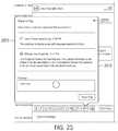
- FIG. 21illustrates the agent having popped-out the Current Conversations window of FIG. 20 , and clicking on the “raise flag” button of the popped out window to ask a supervisor for help, according to some implementations.
- FIG. 22illustrates the Raise a Flag pop-out according to some implementations.
- FIG. 23illustrates the raise a flag pop-out after the agent has entered a message for his supervisor, and how to close the raise a flag pop-out, according to some implementations.
- FIG. 24illustrates the popped-out chat window of FIGS. 21 and 22 now showing snippets of the raise a flag and whisper activity within the window, and an indication of a new whisper message, according to some implementations.
- FIG. 25illustrates the result of re-opening the raise a flag pop-out to view the whisper, according to some implementations.
- Some implementations described and referenced hereinare directed to systems, apparatus, computer-implemented methods and computer-readable storage media for dynamically updating emails.
- a database systemmight display a case associated with a customer support query.
- the database systemmay initiate a search for other cases related to the new case.
- the database systemmay extract relevant terms from the title and/or description provided in the new case using a term weighting algorithm, such as more like this (MLT).
- MHTterm weighting algorithm
- the database systemidentifies articles linked to the related cases, ranks the articles, and causes the articles to be displayed on a remote user system in an order based on the ranking.
- the database systemmay rank the articles based on a number of related cases linked to the articles.
- the database systemalso may rank the article based on other parameters, such as relevancy scores for the related cases, labels assigned to the cases, last modified dates of the related cases, etc.
- the database systemmay identify more relevant articles by first finding related cases that use a similar vocabulary to describe similar customer problems. The database system then identifies the articles that were previously determined to help resolve the prior problems. Thus, the database system may bridge the gap between vocabularies used by customers to describe problems and vocabularies used in articles to describe solutions to those problems.
- the users described hereinare users (or “members”) of an interactive online “enterprise social network,” also referred to herein as an “enterprise social networking system,” an “enterprise collaborative network,” or more simply as an “enterprise network.”
- entity social networkalso referred to herein as an “enterprise social networking system,” an “enterprise collaborative network,” or more simply as an “enterprise network.”
- Such online enterprise networksare increasingly becoming a common way to facilitate communication among people, any of whom can be recognized as enterprise users.
- Chatter®provided by salesforce.com, inc. of San Francisco, Calif.
- salesforce.com, inc.is a provider of enterprise social networking services, customer relationship management (CRM) services and other database management services, any of which can be accessed and used in conjunction with the techniques disclosed herein in some implementations.
- CRMcustomer relationship management
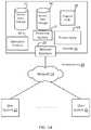
- FIG. 1Ashows a block diagram of an example of an environment 10 in which an on-demand database service can be used in accordance with some implementations.
- the environment 10includes user systems 12 , a network 14 , a database system 16 (also referred to herein as a “cloud-based system”), a processor system 17 , an application platform 18 , a network interface 20 , tenant database 22 for storing tenant data 23 , system database 24 for storing system data 25 , program code 26 for implementing various functions of the system 16 , and process space 28 for executing database system processes and tenant-specific processes, such as running applications as part of an application hosting service.
- environment 10may not have all of these components or systems, or may have other components or systems instead of, or in addition to, those listed above.
- the environment 10is an environment in which an on-demand database service exists.
- An on-demand database servicesuch as that which can be implemented using the system 16 , is a service that is made available to users outside of the enterprise(s) that own, maintain or provide access to the system 16 . As described above, such users generally do not need to be concerned with building or maintaining the system 16 . Instead, resources provided by the system 16 may be available for such users' use when the users need services provided by the system 16 ; that is, on the demand of the users.
- Some on-demand database servicescan store information from one or more tenants into tables of a common database image to form a multi-tenant database system (MTS).
- MTSmulti-tenant database system
- multi-tenant database systemcan refer to those systems in which various elements of hardware and software of a database system may be shared by one or more customers or tenants. For example, a given application server may simultaneously process requests for a great number of customers, and a given database table may store rows of data such as feed items for a potentially much greater number of customers.
- a database imagecan include one or more database objects.
- RDBMSrelational database management system
- a relational database management system (RDBMS) or the equivalentcan execute storage and retrieval of information against the database object(s).
- Application platform 18can be a framework that allows the applications of system 16 to execute, such as the hardware or software infrastructure of the system 16 .
- the application platform 18enables the creation, management and execution of one or more applications developed by the provider of the on-demand database service, users accessing the on-demand database service via user systems 12 , or third party application developers accessing the on-demand database service via user systems 12 .
- the system 16implements a web-based customer relationship management (CRM) system.
- the system 16includes application servers configured to implement and execute CRM software applications as well as provide related data, code, forms, renderable web pages and documents and other information to and from user systems 12 and to store to, and retrieve from, a database system related data, objects, and Web page content.
- CRMcustomer relationship management
- data for multiple tenantsmay be stored in the same physical database object in tenant database 22 .
- tenant datais arranged in the storage medium(s) of tenant database 22 so that data of one tenant is kept logically separate from that of other tenants so that one tenant does not have access to another tenant's data, unless such data is expressly shared.
- the system 16also implements applications other than, or in addition to, a CRM application.
- the system 16can provide tenant access to multiple hosted (standard and custom) applications, including a CRM application.
- User (or third party developer) applicationswhich may or may not include CRM, may be supported by the application platform 18 .
- the application platform 18manages the creation and storage of the applications into one or more database objects and the execution of the applications in one or more virtual machines in the process space of the system 16 .
- each system 16is configured to provide web pages, forms, applications, data and media content to user (client) systems 12 to support the access by user systems 12 as tenants of system 16 .
- system 16provides security mechanisms to keep each tenant's data separate unless the data is shared.
- MTSMobility Management Entity
- theymay be located in close proximity to one another (for example, in a server farm located in a single building or campus), or they may be distributed at locations remote from one another (for example, one or more servers located in city A and one or more servers located in city B).
- each MTScould include one or more logically or physically connected servers distributed locally or across one or more geographic locations.
- serveris meant to refer to a computing device or system, including processing hardware and process space(s), an associated storage medium such as a memory device or database, and, in some instances, a database application (for example, OODBMS or RDBMS) as is well known in the art. It should also be understood that “server system” and “server” are often used interchangeably herein.
- database objects described hereincan be implemented as part of a single database, a distributed database, a collection of distributed databases, a database with redundant online or offline backups or other redundancies, etc., and can include a distributed database or storage network and associated processing intelligence.
- the network 14can be or include any network or combination of networks of systems or devices that communicate with one another.
- the network 14can be or include any one or any combination of a LAN (local area network), WAN (wide area network), telephone network, wireless network, cellular network, point-to-point network, star network, token ring network, hub network, or other appropriate configuration.
- the network 14can include a TCP/IP (Transfer Control Protocol and Internet Protocol) network, such as the global internetwork of networks often referred to as the “Internet” (with a capital “I”).
- the Internetwill be used in many of the examples herein. However, it should be understood that the networks that the disclosed implementations can use are not so limited, although TCP/IP is a frequently implemented protocol.
- the user systems 12can communicate with system 16 using TCP/IP and, at a higher network level, other common Internet protocols to communicate, such as HTTP, FTP, AFS, WAP, etc.
- each user system 12can include an HTTP client commonly referred to as a “web browser” or simply a “browser” for sending and receiving HTTP signals to and from an HTTP server of the system 16 .
- HTTP servercan be implemented as the sole network interface 20 between the system 16 and the network 14 , but other techniques can be used in addition to or instead of these techniques.
- the network interface 20 between the system 16 and the network 14includes load sharing functionality, such as round-robin HTTP request distributors to balance loads and distribute incoming HTTP requests evenly over a number of servers.
- each of the serverscan have access to the MTS data; however, other alternative configurations may be used instead.
- the user systems 12can be implemented as any computing device(s) or other data processing apparatus or systems usable by users to access the database system 16 .
- any of user systems 12can be a desktop computer, a work station, a laptop computer, a tablet computer, a handheld computing device, a mobile cellular phone (for example, a “smartphone”), or any other Wi-Fi-enabled device, wireless access protocol (WAP)-enabled device, or other computing device capable of interfacing directly or indirectly to the Internet or other network.
- WAPwireless access protocol
- each user system 12typically executes an HTTP client, for example, a web browsing (or simply “browsing”) program, such as a web browser based on the WebKit platform, Microsoft's Internet Explorer browser, Netscape's Navigator browser, Opera's browser, Mozilla's Firefox browser, or a WAP-enabled browser in the case of a cellular phone, PDA or other wireless device, or the like, allowing a user (for example, a subscriber of on-demand services provided by the system 16 ) of the user system 12 to access, process and view information, pages and applications available to it from the system 16 over the network 14 .
- a web browsingor simply “browsing” program
- Each user system 12also typically includes one or more user input devices, such as a keyboard, a mouse, a trackball, a touch pad, a touch screen, a pen or stylus or the like, for interacting with a graphical user interface (GUI) provided by the browser on a display (for example, a monitor screen, liquid crystal display (LCD), light-emitting diode (LED) display, among other possibilities) of the user system 12 in conjunction with pages, forms, applications and other information provided by the system 16 or other systems or servers.
- GUIgraphical user interface
- the user interface devicecan be used to access data and applications hosted by system 16 , and to perform searches on stored data, and otherwise allow a user to interact with various GUI pages that may be presented to a user.
- implementationsare suitable for use with the Internet, although other networks can be used instead of or in addition to the Internet, such as an intranet, an extranet, a virtual private network (VPN), a non-TCP/IP based network, any LAN or WAN or the like.
- VPNvirtual private network
- non-TCP/IP based networkany LAN or WAN or the like.
- the users of user systems 12may differ in their respective capacities, and the capacity of a particular user system 12 can be entirely determined by permissions (permission levels) for the current user of such user system. For example, where a salesperson is using a particular user system 12 to interact with the system 16 , that user system can have the capacities allotted to the salesperson. However, while an administrator is using that user system 12 to interact with the system 16 , that user system can have the capacities allotted to that administrator. Where a hierarchical role model is used, users at one permission level can have access to applications, data, and database information accessible by a lower permission level user, but may not have access to certain applications, database information, and data accessible by a user at a higher permission level. Thus, different users generally will have different capabilities with regard to accessing and modifying application and database information, depending on the users' respective security or permission levels (also referred to as “authorizations”).
- permissionsalso referred to as “authorizations”.
- each user system 12 and some or all of its componentsare operator-configurable using applications, such as a browser, including computer code executed using a central processing unit (CPU) such as an Intel Pentium® processor or the like.
- a central processing unitsuch as an Intel Pentium® processor or the like.
- the system 16 (and additional instances of an MTS, where more than one is present) and all of its componentscan be operator-configurable using application(s) including computer code to run using the processor system 17 , which may be implemented to include a CPU, which may include an Intel Pentium® processor or the like, or multiple CPUs.
- the system 16includes tangible computer-readable media having non-transitory instructions stored thereon/in that are executable by or used to program a server or other computing system (or collection of such servers or computing systems) to perform some of the implementation of processes described herein.
- computer program code 26can implement instructions for operating and configuring the system 16 to intercommunicate and to process web pages, applications and other data and media content as described herein.
- the computer code 26can be downloadable and stored on a hard disk, but the entire program code, or portions thereof, also can be stored in any other volatile or non-volatile memory medium or device as is well known, such as a ROM or RAM, or provided on any media capable of storing program code, such as any type of rotating media including floppy disks, optical discs, digital versatile disks (DVD), compact disks (CD), microdrives, and magneto-optical disks, and magnetic or optical cards, nanosystems (including molecular memory ICs), or any other type of computer-readable medium or device suitable for storing instructions or data.
- any other volatile or non-volatile memory medium or devicesuch as a ROM or RAM
- any media capable of storing program codesuch as any type of rotating media including floppy disks, optical discs, digital versatile disks (DVD), compact disks (CD), microdrives, and magneto-optical disks, and magnetic or optical cards, nanosystems (including molecular memory ICs), or any other type
- program codemay be transmitted and downloaded from a software source over a transmission medium, for example, over the Internet, or from another server, as is well known, or transmitted over any other existing network connection as is well known (for example, extranet, VPN, LAN, etc.) using any communication medium and protocols (for example, TCP/IP, HTTP, HTTPS, Ethernet, etc.) as are well known.
- computer code for the disclosed implementationscan be realized in any programming language that can be executed on a server or other computing system such as, for example, C, C++, HTML, any other markup language, JavaTM, JavaScript, ActiveX, any other scripting language, such as VBScript, and many other programming languages as are well known may be used.
- JavaTMis a trademark of Sun Microsystems, Inc.
- FIG. 1Bshows a block diagram of example implementations of elements of FIG. 1A and example interconnections between these elements according to some implementations. That is, FIG. 1B also illustrates environment 10 , but FIG. 1B , various elements of the system 16 and various interconnections between such elements are shown with more specificity according to some more specific implementations.
- the user system 12includes a processor system 12 A, a memory system 12 B, an input system 12 C, and an output system 12 D.
- the processor system 12 Acan include any suitable combination of one or more processors.
- the memory system 12 Bcan include any suitable combination of one or more memory devices.
- the input system 12 Ccan include any suitable combination of input devices, such as one or more touchscreen interfaces, keyboards, mice, trackballs, scanners, cameras, or interfaces to networks.
- the output system 12 Dcan include any suitable combination of output devices, such as one or more display devices, printers, or interfaces to networks.
- the network interface 20is implemented as a set of HTTP application servers 100 1 - 100 N .
- Each application server 100also referred to herein as an “app server”, is configured to communicate with tenant database 22 and the tenant data 23 therein, as well as system database 24 and the system data 25 therein, to serve requests received from the user systems 12 .
- the tenant data 23can be divided into individual tenant storage spaces 112 , which can be physically or logically arranged or divided.
- user storage 114 and application metadata 116can similarly be allocated for each user. For example, a copy of a user's most recently used (MRU) items can be stored to user storage 114 . Similarly, a copy of MRU items for an entire organization that is a tenant can be stored to tenant storage space 112 .
- MRUmost recently used
- the process space 28includes system process space 102 , individual tenant process spaces 104 and a tenant management process space 110 .
- the application platform 18includes an application setup mechanism 38 that supports application developers' creation and management of applications. Such applications and others can be saved as metadata into tenant database 22 by save routines 36 for execution by subscribers as one or more tenant process spaces 104 managed by tenant management process 110 , for example. Invocations to such applications can be coded using PL/SOQL 34 , which provides a programming language style interface extension to API 32 . A detailed description of some PL/SOQL language implementations is discussed in commonly assigned U.S. Pat. No.
- the system 16 of FIG. 1Balso includes a user interface (UI) 30 and an application programming interface (API) 32 to system 16 resident processes to users or developers at user systems 12 .
- UIuser interface
- APIapplication programming interface
- the environment 10may not have the same elements as those listed above or may have other elements instead of, or in addition to, those listed above.
- Each application server 100can be communicably coupled with tenant database 22 and system database 24 , for example, having access to tenant data 23 and system data 25 , respectively, via a different network connection.
- one application server 100 1can be coupled via the network 14 (for example, the Internet)
- another application server 100 N-1can be coupled via a direct network link
- another application server 100 Ncan be coupled by yet a different network connection.
- Transfer Control Protocol and Internet Protocolare examples of typical protocols that can be used for communicating between application servers 100 and the system 16 .
- TCP/IPTransfer Control Protocol and Internet Protocol
- each application server 100is configured to handle requests for any user associated with any organization that is a tenant of the system 16 . Because it can be desirable to be able to add and remove application servers 100 from the server pool at any time and for various reasons, in some implementations there is no server affinity for a user or organization to a specific application server 100 .
- an interface system implementing a load balancing function(for example, an F5 Big-IP load balancer) is communicably coupled between the application servers 100 and the user systems 12 to distribute requests to the application servers 100 .
- the load balanceruses a least-connections algorithm to route user requests to the application servers 100 .
- system 16can be a multi-tenant system in which system 16 handles storage of, and access to, different objects, data and applications across disparate users and organizations.
- one tenantcan be a company that employs a sales force where each salesperson uses system 16 to manage aspects of their sales.
- a usercan maintain contact data, leads data, customer follow-up data, performance data, goals and progress data, etc., all applicable to that user's personal sales process (for example, in tenant database 22 ).
- tenant database 22for example, in tenant database 22 .
- the usercan manage his or her sales efforts and cycles from any of many different user systems. For example, when a salesperson is visiting a customer and the customer has Internet access in their lobby, the salesperson can obtain critical updates regarding that customer while waiting for the customer to arrive in the lobby.
- the user systems 12(which also can be client systems) communicate with the application servers 100 to request and update system-level and tenant-level data from the system 16 .
- Such requests and updatescan involve sending one or more queries to tenant database 22 or system database 24 .
- the system 16(for example, an application server 100 in the system 16 ) can automatically generate one or more SQL statements (for example, one or more SQL queries) designed to access the desired information.
- System database 24can generate query plans to access the requested data from the database.
- the term “query plan”generally refers to one or more operations used to access information in a database system.
- Each databasecan generally be viewed as a collection of objects, such as a set of logical tables, containing data fitted into predefined or customizable categories.
- a “table”is one representation of a data object, and may be used herein to simplify the conceptual description of objects and custom objects according to some implementations. It should be understood that “table” and “object” may be used interchangeably herein.
- Each tablegenerally contains one or more data categories logically arranged as columns or fields in a viewable schema. Each row or element of a table can contain an instance of data for each category defined by the fields.
- a CRM databasecan include a table that describes a customer with fields for basic contact information such as name, address, phone number, fax number, etc.
- Another tablecan describe a purchase order, including fields for information such as customer, product, sale price, date, etc.
- standard entity tablescan be provided for use by all tenants.
- such standard entitiescan include tables for case, account, contact, lead, and opportunity data objects, each containing pre-defined fields.
- entityalso may be used interchangeably with “object” and “table.”
- tenantsare allowed to create and store custom objects, or may be allowed to customize standard entities or objects, for example by creating custom fields for standard objects, including custom index fields.
- custom objectsCommonly assigned U.S. Pat. No. 7,779,039, titled CUSTOM ENTITIES AND FIELDS IN A MULTI-TENANT DATABASE SYSTEM, by Weissman et al., issued on Aug. 17, 2010, and hereby incorporated by reference in its entirety and for all purposes, teaches systems and methods for creating custom objects as well as customizing standard objects in a multi-tenant database system.
- all custom entity data rowsare stored in a single multi-tenant physical table, which may contain multiple logical tables per organization. It is transparent to customers that their multiple “tables” are in fact stored in one large table or that their data may be stored in the same table as the data of other customers.
- a methodmay include displaying a user interface comprising at least two windows, a first window displaying a live chat with a first individual and at least one of the remaining windows displaying content related to the live chat.
- the methodmay further include receiving an indication to pop-out the first window, and in response, displaying the first window as a separate moveable window, and displaying, within an original area of the first window, additional content related to one of the live chat or the first individual.
- the methodmay further include receiving an indication from a user to change the live chat to be with a second individual, and in response to the indication: displaying the live chat with the second individual in the separate moveable window; and displaying content related to the second individual in the at least one of the remaining windows.
- a computer programmay be stored on a storage medium for interactively displaying content.
- the computer programmay include a set of instructions operable to cause a computer to cause a user interface to display at least two windows, a first window displaying a live chat with a first individual and at least one of the remaining windows displaying content related to the live chat.
- the instructionsmay be further operable to receive a first indication to pop-out the first window, and in response to the first indication, cause the first window to be displayed as a separate moveable window, and cause to be displayed, within an original area of the first window, additional content related to one of the live chat or the first individual.
- the instructionsmay be further operable to receive a second indication from a user to change the live chat to be with a second individual, and in response to the indication, cause the live chat with the second individual to be displayed in the separate moveable window, and cause content related to the second individual to be displayed in the at least one of the remaining windows.
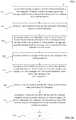
- FIG. 2shows an example process for popping out a chat window from a user interface (UI), changing chat customers and preserving context according to some implementations.
- UIuser interface
- FIG. 2shows an example process for popping out a chat window from a user interface (UI), changing chat customers and preserving context according to some implementations.
- operational flow for a process 200 of popping out a window from a UI comprising at least two adjacent windowsis illustrated. It is noted that for ease of understanding, the following description of process 200 will make reference to various ones of FIGS. 6-13C , which illustrate example screen shots according to various embodiments.
- process 200may include operations performed at blocks 210 - 255 .
- the operationsmay be performed by User System 12 of FIG. 1A , for example, when accessing System 16 .
- process 200may begin at block 210 .
- a devicesuch as User System 12 of FIG. 1A , may cause a UI to display at least two windows, a first window displaying a first live chat with a first individual, and at least one of the remaining windows displaying content related to one of the first individual or the first chat.
- An example of such a UIis shown in FIGS. 6 and 7 .
- the user interface 600 or 700may present relevant information to a user, who, in embodiments, may be a customer service representative or agent. Additionally, the user interface may, for example, provide an environment in which multiple customer chats may be conducted by the customer service representative or agent, with only one of them being the “live” chat at any given time. It is understood that, as used herein, and in the claims, a “live” or “active” chat is the chat in which the agent is currently messaging. In embodiments, multiple customer chats may be conducted substantially simultaneously, where an agent may switch between several chats as new messages are respectively posted in the chats by the respective individuals involved. An example of this is described below in connection with FIGS. 12 and 13A-13C . Thus, when the agent switched between chats, the new chat becomes the “live” chat.
- process 200may proceed to block 220 , where the device may receive an indication to pop out the window of the UI that is displaying the live chat.
- the windowmay be, for example, Current Conversation window 715 of FIG. 7 , or the like.
- a window displaying an active chatsometimes referred to herein as a “chat window”, is understood to be a window or other element of a UI which displays messages exchanged between two or more parties. Chat windows are commonly used in Uls of websites or programs that allow a customer or potential customer of a business or entity to engage in on-line conversations with a customer service representative of the business or entity.
- each party to the chatmay see a chat window interface in which they may type messages, attach or send images or audio files, embed links to such content, or the like.
- Current Conversations window 715displays a current live chat 716 between customer service agent Jason Dewar and a first customer Andy Martinez. This is also indicated by the highlighted sub-window 711 of My Chats window 710 , which shows the beginning of the last message in the chat, as shown in full at 735 .
- an indication to pop-out the chat windowmay be communicated to the device in various ways, such as, for example, the user clicking on a button or widget, speaking a command, typing in a command or code for a command, or the like.
- a usermay communicate such a command by clicking or engaging with a pop-out button, such as, for example, button 820 in FIG. 8 .
- the indicationmay be automatic, generated by the device itself.
- This “automatic pop-out”may be set by one or more system parameters.
- the chat shown in the bottom of Current Conversations window 715 of FIG. 7may be set to automatically pop-out as a separate window after a pre-defined time has elapsed in the chat.
- process 200may proceed to block 230 , where the device, in response to the indication, may cause the first window to be displayed as a separate moveable window, either in front of the UI or on a separate monitor.
- a devicemay “fill the hole” left by the popping out of the chat window by displaying additional content related to the first live chat in the area of the Current Conversations window previously occupied by the display of the live chat.
- the additional contentmay include, for example, past chats with the first individual, or, for example, details relevant to the live chat or the first individual.
- window 930 of FIG. 9which now displays, in the former “live chat” portion of the window, past chats 919 with customer “Andy Martinez” while the live chat with Andy Martinez is displayed in now popped-out live chat window 915 .
- a usermay choose whether past chats are displayed, or other details 917 are displayed, once the live chat is displayed in separate moveable window 915 .
- the space previously occupied by the component in the consolemay be filled with any components from the same column which were below the popped out component. In other words the rest of the column slides to fill the space.
- FIG. 9where the most current messages are shown at the top of the space.
- process 200may proceed to query block 240 , where the device may determine if it has received a user indication to change to a second live chat with a second individual.
- a customer service agentmay simultaneously hold several ongoing chats with customers, the one he currently responds to being known as the “live” or “active” chat. This may be an efficient use of time where, for example, the customer service agent proposes solutions to a given individual to go and try to resolve their problem or issue, or, for example, where the customer service agent has previously sent instructions, or links to instructions, for a customer to read, and there is some lag time before the individual reports back via a new chat message. In such situations, rather than just wait, the customer service agent may change the live chat to one of the other ongoing chats, where, for example, an individual from a previously live (but still ongoing) chat may post a new message for the customer service agent.
- the customer service agentmay interact with the UI to signal such a change, such as, for example, is shown in FIGS. 11 and 13 , where an agent, seeing a new message arrive from Taylor Watson-Rice, as shown, for example, by indicator 1113 of FIG. 11 , switches his live chat (which is displayed in separate and moveable window 915 ) from individual Andy Martinez to individual Taylor Watson-Rice, by, for example, highlighting block 912 of the My Chats window of the UI.
- FIG. 13AThe result of this change by the customer service agent is shown, for example in FIG. 13A , where the live chat displayed in separate and moveable window 1315 is now that with Taylor Watson-Rice, and thus block 1312 in FIG. 13A is now highlighted, and block 1311 is now darkened or ghosted, as shown.
- FIG. 13Athe various supporting fields in the entire UI which provide past chat messages, or additional contextual information about the individual in the current live chat, have now changed to relate to Taylor Watson-Rice.
- the separate componentsmay integrate with each other, so that changes in one are automatically reflected in the contents of the others.
- This same connectionmay apply in embodiments, when one component is “popped out” of the console space itself.
- the separate and moveable windowwill continue to be integrated to the other workspace components.
- process 200may return to block 230 , and continue displaying the live chat in the separate and moveable window, such as is shown, for example, in FIG. 9 with individual Andy Martinez in separate and moveable window 915 in FIG. 9 .
- process 200may proceed to block 250 , where, in response to the user indication, the device may cause the separate and moveable window to display the second live chat with the second individual, and cause the at least one of the remaining windows to display content related to one of the second individual or the second chat, as described above in connection with FIGS. 9 and 13A .
- process 200may then end at block 255 .
- FIG. 3depicts operational flow for a process 300 of popping out a first chat window from a UI, changing chat customers and preserving UI context while allowing the first popped out chat window to remain displayed as inactive, according to some implementations. It is noted that for ease of understanding, the following description of process 300 will make reference to various ones of FIGS. 9, and 13B through 13C , and in particular which illustrate example screen shots according to various embodiments.
- process 300may include operations performed at blocks 310 - 360 .
- the operations of process 300may be performed by User System 12 of FIG. 1A , for example, when accessing System 16 .
- process 300may begin at block 310 .
- a devicesuch as User System 12 of FIG. 1A , may cause a UI to display at least two windows, one of them displaying an active chat with a first individual, and may cause the other windows to display content relating to the first individual.
- An example of such a UIis shown in FIGS. 6 and 7 , as described above in connection with FIG. 2 , which need not be repeated here.
- process 300may proceed to block 320 , where the device may receive an indication to pop out the window of the UI that is displaying the active chat.
- the windowmay be, for example, Current Conversation window 715 of FIG. 7 , or the like.
- Current Conversations window 715displays a current live chat 716 between customer service agent Jason Dewar and a first individual Andy Martinez. This is also indicated by the highlighted sub-window 711 of My Chats window 710 , which shows the beginning of the last message in the chat, as shown in full at 735 .
- an indication to pop-out the chat windowmay be communicated to the device in various ways, such as, for example, the user clicking on a button or widget, speaking a command, typing in a command or code for a command, or the like.
- a usermay communicate such a command by clicking or engaging with a pop-out button, such as, for example, button 820 in FIG. 8 .
- the indicationmay be automatic, generated by the device itself.
- This “automatic pop-out”may be set by one or more system parameters.
- the chat shown in the bottom of Current Conversations window 715 of FIG. 7may be set to automatically pop-out as a separate window after a pre-defined time has elapsed in the chat.
- This automatic pop-outmay occur for specified issue types or by user preference.
- the usermay configure that whenever a chat conversation is started, automatically pop out the component. Or, for example, it may only pop-out when a certain amount of time has elapsed in the chat, to not needlessly clutter the UI for very short, easily resolved chats.
- Either of these example parametersmay, in embodiments, be stored as a UI default for all cases of a certain type or as a user preference.
- process 300may proceed to block 330 , where the device, in response to the indication, may cause the UI to display the active chat in a first separate moveable window, and display prior messages of the active chat in the original active chat window of the UI, as shown, for example, in FIG. 9 , and as discussed above in connection with FIG. 2 .
- process 300may proceed to block 340 , where the device may receive a user indication to change the active chat to be with a second individual. From block 340 , process 300 may proceed to block 350 , where the device, in response to the user indication, may cause the UI to display the active chat with the second individual in the active chat window, and to display the popped-out chat window with the chat with the first individual as non-active. This is shown, for example, by comparison of FIGS. 9 and 13B .
- an agentseeing a new message arrive from Taylor Watson-Rice, as shown, for example, by indicator 1113 of FIG. 11 , may switch his live chat (which is displayed in separate and moveable window 915 ) from first individual Andy Martinez to individual Taylor Watson-Rice, by, for example, highlighting block 912 of the My Chats window of the UI.
- the result of this change by the customer service agentis shown, for example in FIG. 13B , where the live chat is displayed in a bottom portion of My Conversations window 1330 , and is now with individual Taylor Watson-Rice, and thus block 1312 in FIG. 13B is now highlighted, and block 1311 is now darkened or ghosted, as shown.
- the various supporting fields in the entire UIwhich provide past chat messages, or additional contextual information about the individual in the current live chat, have now changed to relate to Taylor Watson-Rice.
- separate moveable window 1325which continues to display messages from the previous live chat with Andy Martinez, is shown as inactive, as the banner across its top is shown in grey.
- the existing pop outmay not change, and rather, may continue to be displayed, but may be displayed to indicate that is has been is deselected (such as, for example, by being shown in grey frame), and the chat window 1330 may show the new chat (in this example, with Taylor Watson-Rice).
- the agentmay pop out the new active chat from widow 1330 into a second separate moveable window as well, of course, but that must be affirmatively done.
- a parameteris set for a time-elapsed automatic pop-out, that may occur as well, in embodiments.
- a parameterin contrast to the process of block 250 of FIG. 2 , each time a user selects a new active chat, it may first appear only as not popped out, and the content of any already popped-out chat window is not changed, and the previously popped-out window continues to be displayed, only the window itself may be shown as inactive.
- process 300may proceed to block 355 , where, the device may receive an indication to pop out the window of the UI that is displaying the active chat, which is now with the second individual.
- process 300may proceed to block 360 , where the device, in response to the indication, may cause the UI to display the active chat in a second separate moveable window, and display prior messages of the active chat (here with the second individual) in the original active chat window of the UI, as shown, for example, in FIG. 13C .
- a second separate moveable window 1327is now displayed, in response to the indication.
- a second, now active, separate moveable window 1327with an active banner 1329 (shown in a darker color), indicating that it is the active live chat window, and first separate moveable window 1325 , with an inactive banner 1339 (shown in a greyed or lighter color), indicating that it is an inactive window showing messages from a prior chat.
- prior messages of the active chathere with the second individual Taylor Watson-Rice are displayed in the original active chat portion 1331 of the Current Conversation window 1330 of UI 1300 C, as shown.
- an indication to pop-out the chat windowmay be communicated to the device in various ways, such as, for example, the user clicking on a button or widget, speaking a command, typing in a command or code for a command, or the like.
- a usermay communicate such a command by clicking or engaging with a pop-out button, such as, for example, button 1320 in FIG. 13B .
- the indicationmay be automatic, generated by the device itself, as described above, after a chat lasts for a certain amount of time.
- FIGS. 13B through 13Dthere would not be an automatic pop-out of the live chat when it begins. This so as not to clutter the UI with numerous separate moveable windows each time a user changes the live chat, inasmuch as all previous popped out windows remain displayed, albeit inactive, upon a change of live chat individuals.
- process 300may proceed to block 365 , where it may terminate.
- process 300 Amay include operations performed at blocks 331 - 376 .
- the operationsmay be performed by User System 12 of FIG. 1A , for example, when accessing System 16 .
- process 300 Ais an enhanced version of the example process 300 of FIG. 3 , where process 300 A further includes switching an active chat between multiple popped out chat windows, according to some implementations.
- blocks 331 through 361 of process 3 Aare completely analogous to blocks 330 through 360 , respectively, of process 300 , and need not be further described.
- the devicemay display the active chat with the second individual in a second separate moveable window, and display prior chat messages with the second individual in the active chat window of the multi-window UI. As noted above, this situation is illustrated, for example, in FIG. 13C .
- process 300 Amay proceed to block 366 , where the device may receive a user indication to change the individual of the active chat back to the first individual.
- the devicemay receive a user indication to change the individual of the active chat back to the first individual.
- a second, now active, separate moveable window 1327where there are two separate moveable windows: a second, now active, separate moveable window 1327 , with an active banner 1329 (shown in a darker color), indicating that it is the active live chat window, which displays message sin a live chat with Taylor Watson-Rice, and a first separate moveable window 1325 , with an inactive banner 1339 (shown in a greyed or lighter color), indicating that it is an inactive window, showing messages from the prior chat with first individual Andy Martinez.
- the user indication at block 366now requests the device to change back to a live chat with Andy Martinez.
- the user indication to change the individual in the live chatmay be performed using any of the methods as described above, or, for example, may be performed simply by a user clicking anywhere within an inactive separate and moveable window, if the individual desired to now be in the live chat was previously in a live chat with the user, and thus an inactive separate and moveable window is still being displayed for that individual.
- the usermay, in embodiments, easily change form one live chat to another simply by activating one of the displayed inactive separate moveable windows.
- process 300 Amay proceed to block 371 , where the device may, in response to the user indication, display the first separate moveable window as active, display prior chat messages with the first individual in the designated active chat window of the multi-window UI, and display the second separate moveable window as inactive.
- the devicemay, in response to the user indication, display the first separate moveable window as active, display prior chat messages with the first individual in the designated active chat window of the multi-window UI, and display the second separate moveable window as inactive.
- FIG. 13Dwhere now first separate moveable window 1339 , displaying a live chat with Andy Martinez, may be displayed as active (as seen by darker banner 1339 ), and prior messages of the active chat (here with the first individual Andy Martinez) are displayed in the original active chat portion 1331 of the Current Conversation window 1330 of UI 1300 D, as shown.
- UI 1300 Dmay display second separate moveable window 1327 , which displays messages with now prior chat individual Taylor Watson-Rice, as inactive (as seen by grey
- process 300 Amay proceed to block 376 , where it may terminate.
- any number of separate moveable windowsmay be displayed, inasmuch as each time a user changes to a new individual for a live chat, the user may decide to pop-out that new window, as illustrated, for example, in FIGS. 13B and 13C .
- the usermay have decided not to return to a live chat with former live chat partner Andy Martinez, but to change to a live chat with another individual listed in the My Chats window 1311 , and then pop out the live chat window, as per blocks 341 through 361 of FIG. 3A , thereby causing the UI to display a new separate moveable window with the new individual.
- the usermay pop the separate moveable window back in to the UI, such as, for example, by clicking on pop-in icon 925 , as shown in FIG. 9 , or pop-in icon 1345 , as shown in FIG. 13D .
- computer device 400may include one or more processors 402 , memory controller 403 , and system memory 404 .
- processors 402may include one or more processor cores and/or hardware accelerator 405 .
- hardware accelerator 405may include, but is not limited to, programmed field programmable gate arrays (FPGA).
- Memory controller 403may be any one of a number of memory controllers known in the art.
- System memory 404may include any known volatile or non-volatile memory.
- computer device 400may include mass storage device(s) 406 (such as solid state drives), input/output device interface 408 (to interface with various input/output devices, such as, mouse, cursor control, display device (including touch sensitive screen), and so forth) and communication interfaces 510 (such as network interface cards, modems and so forth).
- mass storage device(s) 406such as solid state drives
- input/output device interface 408to interface with various input/output devices, such as, mouse, cursor control, display device (including touch sensitive screen), and so forth
- communication interfaces 510such as network interface cards, modems and so forth.
- communication interfaces 510may support wired or wireless communication, including near field communication.
- the elementsmay be coupled to each other via system bus 512 , which may represent one or more buses. In the case of multiple buses, they may be bridged by one or more bus bridges (not shown).
- system memory 404 and mass storage device(s) 406may be employed to store a working copy and a permanent copy of the executable code of the programming instructions of an operating system, one or more applications, Web Browser 221 , Extension 223 , Email Server 231 , Other 233 , Message Hosting Module 241 and Notification Module 242 , as well as each of their respective counterparts shown in the alternate system 200 B of FIG. 2B , collectively referred to as computing logic 422 .
- Extension 223or alternatively Web Browser 221 , or still alternatively Web Browser 221 , in combination with Extension 223 , may be configured to practice (aspects of) processes 200 , 300 and 300 A of FIGS.
- the programming instructionsmay comprise assembler instructions supported by processor(s) 402 or high-level languages, such as, for example, C, that can be compiled into such instructions.
- processor(s) 402or high-level languages, such as, for example, C, that can be compiled into such instructions.
- some of computing logicmay be implemented in hardware accelerator 405 .
- the permanent copy of the executable code of the programming instructions or the bit streams for configuring hardware accelerator 405may be placed into permanent mass storage device(s) 406 in the factory, or in the field, through, for example, a distribution medium (not shown), such as a compact disc (CD), or through communication interface 410 (from a distribution server (not shown)).
- a distribution mediumsuch as a compact disc (CD)
- CDcompact disc
- communication interface 410from a distribution server (not shown)
- the number, capability and/or capacity of these elements 410 - 412may vary, depending on the intended use of example computer device 400 , e.g., whether example computer device 400 is a smartphone, tablet, ultrabook, a laptop, a server, a set-top box, a game console, a camera, and so forth.
- the constitutions of these elements 410 - 412are otherwise known, and accordingly will not be further described.
- FIG. 5illustrates an example computer-readable storage medium having instructions configured to implement all (or portion of) Web Browser 221 , Extension 223 , Email Server 231 , Other 233 , Message Hosting Module 241 , Notification Module 242 , and/or practice (aspects of) processes 200 and 300 of FIGS. 2 and 3 , respectively, earlier described, in accordance with various embodiments.
- computer-readable storage medium 502may include the executable code of a number of programming instructions or bit streams 504 .
- Executable code of programming instructions (or bit streams) 504may be configured to enable a device, e.g., computer device 400 , in response to execution of the executable code/programming instructions (or operation of an encoded hardware accelerator 405 ), to perform (aspects of) process 200 of FIG. 2, 300 of FIGS. 3, and 300A of FIG. 3A , respectively.
- executable code/programming instructions/bit streams 504may be disposed on multiple non-transitory computer-readable storage medium 502 instead.
- computer-readable storage medium 502may be non-transitory.
- executable code/programming instructions 504may be encoded in transitory computer readable medium, such as signals.
- processors 402may be packaged together with a computer-readable storage medium having some or all of computing logic 422 (in lieu of storing in system memory 404 and/or mass storage device 406 ) configured to practice all or selected ones of the operations earlier described with reference to FIGS. 2, 3 and 3A .
- processors 402may be packaged together with a computer-readable storage medium having some or all of computing logic 422 to form a System in Package (SiP).
- SiPSystem in Package
- processors 402may be integrated on the same die with a computer-readable storage medium having some or all of computing logic 422 .
- processors 402may be packaged together with a computer-readable storage medium having some or all of computing logic 422 to form a System on Chip (SoC).
- SoCSystem on Chip
- the SoCmay be utilized in, e.g., but not limited to, a hybrid computing tablet/laptop.
- FIGS. 6-25various screen shots of an example customer service chat interaction is illustrated, where a current conversation window may be popped out of a main UI, and further interacted with, in accordance with various embodiments. These figures are next described.
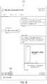
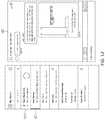
- FIG. 6illustrates an example screen shot of an example customer service agent's main display 600 , with an overlay indicating the function of each of four separate windows which comprise main display 600 .
- the four windowsinclude a “My Chats” window 610 , a “Customer Info” window 620 , a “Current Conversation” window 630 and finally a “Knowledge” window 640 .
- the contents and function of these four windowsare next described with reference to FIG. 7 , which depicts the underlying objects in each window without the overlay.
- Current Conversation window 630may be popped out and separately displayed, either floating above main window 600 , or ported to another screen. In embodiments, when that happens,
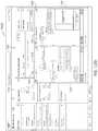
- FIG. 7illustrates detail of the four windows comprising the example main display of FIG. 6 .
- the screen shots depicted in FIGS. 6-25relate to an exemplary fictional customer service representative named “Jason Dewar” who may work for amazon.com. Jason may sometimes be referred to in FIGS. 6-25 , and in their description herein, as “agent Jason.”
- agent Jasonhas exemplary online chats with several fictional individuals or customers, and in the process of conducting those chats uses a live agent window according to various embodiments.
- Two example chats involving agent Jasonwill be discussed as running examples, so as to illustrate functionality according to various embodiments. These include a chat with customer Andy Martinez regarding an issue he has with his Amazon Echo, namely that it was somehow erroneously programmed to communicate in French, and a chat that agent Jason has with customer Taylor Watson-Rice regarding replacing her broken Amazon Echo.
- My Chats window 710includes several customer chats, listed by most recent at the top and least recent at the bottom.
- One of themis a current chat, chat 711 with customer Andy Martinez.
- chat 711 with Andy Martinezis the current chat, its field has a white background, as opposed to the other chats listed in My Chats window 710 which are displayed with shaded backgrounds.
- Current chat 711displays a few words from the last comment in the chat.
- chat 711 with Andy Martinezdisplays the first few words of the last response 735 in the chat: “Sure, no problem, Many customers facing . . . ”, as shown in Current Conversation window 715 .
- Customer Info window 720displays various contextual details to agent Jason regarding the live chat with Andy Martinez. These are provided in the following fields: Contact Detail 721 , Chat Transcript Detail 723 and Case Detail 725 . It is here noted that Case Detail 725 will be described in greater detail below, with reference to FIGS. 15 through 17 .
- Current Conversation window 715displays the last few entries in the chat
- Knowledge window 740displays relevant knowledge to the issue being discussed in the current chat to assist the customer service agent.
- Knowledge window 740there are several displayed blurbs which relate to the Amazon Echo, which may assist a customer service agent in responding to the customer's concerns.
- pop-out button 720appears at the bottom left of Current Conversation window 715 , which, in embodiments, allows a user (here agent Jason) to pop-out the Current Conversation window 715 and have it displayed as a separate entity, either floating above main display 700 , or portable to a separate display, e.g., a second monitor. In either case, in embodiments, after being popped-out, Current Conversation window 715 is independently moveable and sizeable by a user. Once the live chat window is popped-out, agent Jason may review important records at the same time, which may be displayed in the current position of live chat window 715 .
- FIG. 8illustrates a magnified version of Current Conversation window 815 , in accordance with various embodiments, for ease of inspection.
- popped-out widow 915is shown displayed in front of the UI. As may be seen by comparison with FIG. 7 , it displays the exact same content as when it was part of the default UI 700 .
- a usermay, for example, click on pop-out button 925 , which toggles between the popped-out and popped-in states of window 915 .
- the pop-out button 925may appear at the top of popped-out window 915 , as shown, for easy interaction.
- widow 915has not changed any dimension of the UI, and thus, in the area formerly occupied by window 915 , the same header is shown (“My echo only speaks French”) and the “Past Chats” menu item is now active, so that the vacated window now shows past chats that the current customer, Andy Martinez, has had with previous customer service agents. Additionally, “My Chats” window shows the current chat 911 as being with customer “Andy Martinez.”
- FIG. 10depicts a magnified view of popped-out widow 1015 , for ease of inspection.
- FIG. 11illustrates what happens when a new response from one of the ongoing chats, but different than the current chat, comes in.
- FIG. 12presents a magnified version of My Chats window 1210 and popped-out window 1225 for ease of inspection.
- the current chat 1211is still, at this point, with Andy Martinez, and the new message from Taylor Watson-Rice 1212 was received 1 second previously.
- agent Jasonhas now changed his chat to the Taylor Watson-Rice, as shown at 1312 .
- the entire chat consolechanges to the new context, and popped-out window 1315 now displays the pending chat with Taylor Watson-Rice, including her latest response “What are my options.”
- window 1330still displays past chats, but now the past chats are those involving Taylor Watson-Rice.
- box 1330which allows a user, here agent Jason, to create a “case” which is an action item that may be handled by others in the enterprise, and which require more investigation than a customer service agent in a live chat can usually provide.
- FIGS. 13B through 13Dwere described in detail above, in connection with FIGS. 3 and 3A , and need not be further described again in detail. They respectively show the same display as is shown in FIG. 13A , except that they illustrate an alternate embodiment, where a change to a new live chat does not alter a previously popped-out separate moveable window, except to display it as inactive.
- FIG. 13Billustrates the UI interface main display and the popped-out chat window of FIG. 12 , after the agent has changed to a new active chat, according to alternate implementations.
- FIG. 13Cillustrates the UI main display and two popped-out chat windows, after the agent has popped out the active chat window shown in the bottom of UI window 1330 (which displays the new active chat with second individual Taylor Watson-Rice), according to alternate implementations.
- FIG. 13Dillustrates the UI main display and two popped-out chat windows of FIG. 13C , after the agent has changed the active chat back to customer “Andy Martinez”, which causes the second separate moveable window 1327 to be displayed as inactive, according to alternate implementations.
- FIG. 14is a magnified view of popped-out window 1415 , shown in FIGS. 13A and 13C , which displays most recent messages in the chat with Taylor Watson-Rice.
- FIG. 15detail of the “case” box 1530 , described above, is shown.
- a usermay create a new case, using button 1537 , for example, as Jason is about to do for the issue Taylor Watson-Rice has messaged him about.
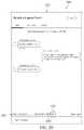
- FIG. 16this depicts the Create Case screen that a user sees following interacting with the create case button 1537 of FIG. 15 .
- the Create Case screenis displayed in place of the normal chat UI, as shown by case indicator 1601 , however, as shown in FIG. 17 , the My Chats window at the far left of the UI, as well as the “Related Cases” window at the far right of the UI, may still be displayed, which is why they are ghosted in FIG. 16 .
- the Create Case screen 1600requires entry of the “case owner” 1643 , in this case amazon.com customer service agent Jason Dewar, the contact for the case 1640 , here Taylor Watson-Rice, and the asset being described or referred to 1645 , here the Amazon Echo Dot, which Taylor Watson-Rice initially contacted customer service about, as shown in her live chat and past chats, as shown in FIG. 13 .
- the popped-out live chat window 1615is still being displayed, inasmuch as it is now—although content wise contextually linked to the UI, it is not part of the UI, and thus independently displayed. In embodiments this may be very useful to a customer service agent, who may wish to refer to the live chat messages when creating a case for that customer.
- FIG. 17presents an exemplary UI displayed to a user once the case has been created.
- the center two windowsdisplay information relative to the case created for Taylor Watson-Rice, the content displayed in the two end windows has not changed.
- menu selector button 1750 for “case”is active
- the My Chats windowindicates that the current chat 1712 is with Taylor Watson-Rice
- box 1751indicates that the most recent activity was creation of a previous case for Taylor Watson-Rice regarding her higher than normal billing statement.
- popped out live chat window 1715remains visible at the bottom right of the screen, where agent Jason has moved it, so as to be able to interact with the case content 1755 .
- FIG. 18presents a magnified view of these two windows.
- FIGS. 19-25relate to an enhanced pop-out window according to various embodiments.
- the enhanced featuresinclude “raise a flag” and “whisper”, which were described above in connection with FIG. 3 .
- features of FIGS. 19-25are equivalent as those described above in connection with FIGS. 7-10 , they will not be further described except in passing.
- FIG. 19depicts an exemplary UI, similar to that of FIG. 7 .
- a current chatis ongoing with customer Andy Martinez, as shown by My Chats indication 1911 .
- the Current Conversation window 1930displays the live chat 1919 with Andy Martinez, who has reached out to Amazon Echo support regarding his Amazon Echo.
- Notableis enhanced toolbar 1935 in the live chat window, which has pop-put button 1920 , but now also flag button 1960 .
- FIG. 20is a magnified view of live chat window 2030 , and the enhanced toolbar just described.
- FIG. 21a situation equivalent to that depicted in FIG. 9 , is shown, where live chat window 2115 has been popped-out, and now separately displayed over the UI in a moveable window.
- Current Conversations window 2130displays past chats 2119 with the customer.
- Popped-out window 2115may be popped back in via button 2125 , as described above.
- flag button 2160is shown, highlighted in a lightly shaded circle. Customer service agent Jason may click on it, or otherwise interact with it, as described above, to ask his supervisor's help.
- the result of interacting with flag button 2160is depicted in FIG. 22 , which shows a new “Raise a Flag” window 2263 displayed over the popped-out chat window 2215 , which “hovers” above flag button 2260 .
- Raise a Flag window 2263may be used to alert agent Jason's supervisor and ask for his or her assistance with a customer service problem.
- FIG. 23a magnified version of Raise a Flag window 2363 is shown.
- agent Jasonhas entered a message in Raise a Flag window 2363 , which he may further edit by engaging “Edit” button 2368 .
- popped-out live chat window 2315In the background is seen popped-out live chat window 2315 , with enhanced toolbar 2335 , including flag button 2360 .
- the shading in flag button 2360here indicates that the Raise a Flag window is open, and once the “X” is pressed by Jason to close the window, then the display of FIG. 24 may be seen.
- FIG. 24depicts popped-out live chat window 2415 .
- the “raise a flag” messaging activityis displayed within the live chat window, but is not visible to the other party to the chat, in this case customer Andy Martinez.
- a “whisper” from “SuperAlly”has been noted. This corresponds to a message response from the supervisor, responding to the message in the flag sent by agent Jason, as shown in FIG. 23 .
- the messageis not yet visible, because agent Jason had closed Raise a Flag window 2363 , as shown in FIG. 23 .
- flag button 2470has a “1” with a circle around it, indicating that a message is in the Raise a Flag queue.
- agent Jasonmust re-open the “Raise a Flag” window. In embodiments, He may do so by clicking or otherwise engaging with flag button 2470 . The result of that action is shown in FIG. 25 .
- FIG. 25a magnified version of now re-opened Raise a Flag window 2563 is shown.
- the response 2572 from SuperAllya “whisper.” It is here called a whisper, inasmuch as it is invisible to the other party to the live chat, the customer, and thus the flag and whisper messaging is only visible internally, to those on the customer service team.
- agent Jasonmay simply interact with, for example, click on, the “X” 2575 on the top right of Raise a Flag window 2563 , and the unencumbered live chat window will be seen, as shown in FIG. 24 .
- implementationsmay be combined in any suitable manner without departing from the spirit and scope of the disclosed implementations. However, other implementations may be directed to specific implementations relating to each individual aspect, or specific combinations of these individual aspects. Additionally, while the disclosed examples may include those with reference to an implementation in which an on-demand database service environment is implemented in a system having an application server providing a front end for an on-demand database service capable of supporting multiple tenants, the present implementations are not limited to multi-tenant databases or deployment on application servers. Implementations may be practiced using other database architectures, i.e., ORACLE®, DB2® by IBM and the like without departing from the scope of the implementations claimed. Thus, in general, implementations may be practiced without use of multi-tenant databases, and without deployment on application servers.
- any of the software components or functions described in this applicationcan be implemented as software code to be executed by one or more processors using any suitable computer language such as, for example, Java, C++ or Perl using, for example, existing or object-oriented techniques.
- the software codecan be stored as a computer- or processor-executable instructions or commands on a physical non-transitory computer-readable medium.
- RAMrandom access memory
- ROMread only memory
- magnetic mediasuch as a hard-drive or a floppy disk
- optical mediumsuch as a compact disk (CD) or DVD (digital versatile disk), flash memory, and the like, or any combination of such storage or transmission devices.
- CDcompact disk
- DVDdigital versatile disk
- Computer-readable media encoded with the software/program codemay be packaged with a compatible device or provided separately from other devices (for example, via Internet download). Any such computer-readable medium may reside on or within a single computing device or an entire computer system, and may be among other computer-readable media within a system or network.
- a computer system, or other computing devicemay include a monitor, printer, or other suitable display for providing any of the results mentioned herein to a user.
Landscapes
- Engineering & Computer Science (AREA)
- Theoretical Computer Science (AREA)
- General Engineering & Computer Science (AREA)
- Human Computer Interaction (AREA)
- Physics & Mathematics (AREA)
- General Physics & Mathematics (AREA)
- Computer Networks & Wireless Communication (AREA)
- Signal Processing (AREA)
- Software Systems (AREA)
- Computing Systems (AREA)
- User Interface Of Digital Computer (AREA)
Abstract
Description
Claims (21)
Priority Applications (1)
| Application Number | Priority Date | Filing Date | Title |
|---|---|---|---|
| US15/874,281US10671248B2 (en) | 2018-01-18 | 2018-01-18 | Live agent chat console |
Applications Claiming Priority (1)
| Application Number | Priority Date | Filing Date | Title |
|---|---|---|---|
| US15/874,281US10671248B2 (en) | 2018-01-18 | 2018-01-18 | Live agent chat console |
Publications (2)
| Publication Number | Publication Date |
|---|---|
| US20190220154A1 US20190220154A1 (en) | 2019-07-18 |
| US10671248B2true US10671248B2 (en) | 2020-06-02 |
Family
ID=67213918
Family Applications (1)
| Application Number | Title | Priority Date | Filing Date |
|---|---|---|---|
| US15/874,281Active2038-04-14US10671248B2 (en) | 2018-01-18 | 2018-01-18 | Live agent chat console |
Country Status (1)
| Country | Link |
|---|---|
| US (1) | US10671248B2 (en) |
Cited By (5)
| Publication number | Priority date | Publication date | Assignee | Title |
|---|---|---|---|---|
| US20190373029A1 (en)* | 2018-05-29 | 2019-12-05 | Freshworks Inc. | Online collaboration platform for collaborating in context |
| US20200160270A1 (en)* | 2018-11-21 | 2020-05-21 | Kony Inc. | System and method for a registration system within an intelligent digital experience development platform |
| US11435881B1 (en)* | 2020-06-29 | 2022-09-06 | United Services Automobile Association (Usaa) | Integrated smart graphical user interface for customer management systems |
| US12086775B2 (en)* | 2023-02-13 | 2024-09-10 | Stodge Inc. | Presenting interaction history including context information on a user interface |
| US12244653B2 (en) | 2023-06-05 | 2025-03-04 | State Farm Mutual Automobile Insurance Company | Inter-channel context transfer intermediary |
Families Citing this family (12)
| Publication number | Priority date | Publication date | Assignee | Title |
|---|---|---|---|---|
| CN108809641B (en)* | 2018-04-18 | 2021-03-12 | 李世伟 | Homepage identification number generation and application method and device |
| US10832002B2 (en)* | 2018-05-08 | 2020-11-10 | International Business Machines Corporation | System and method for scoring performance of chatbots |
| US11449197B2 (en)* | 2019-03-08 | 2022-09-20 | [24]7.ai, Inc. | Agent console for facilitating chat interactions with customers |
| US11790375B2 (en)* | 2019-05-15 | 2023-10-17 | Asapp, Inc. | Flexible capacity in an electronic environment |
| USD1004615S1 (en)* | 2020-03-06 | 2023-11-14 | Salesforce, Inc. | Display screen or portion thereof with graphical user interface |
| USD1000472S1 (en)* | 2020-03-06 | 2023-10-03 | Salesforce, Inc. | Display screen or portion thereof with graphical user interface |
| USD988350S1 (en)* | 2020-03-06 | 2023-06-06 | Slack Technologies, Llc | Display screen or portion thereof with graphical user interface |
| USD1003933S1 (en)* | 2020-03-06 | 2023-11-07 | Salesforce, Inc. | Display screen or portion thereof with graphical user interface |
| US11375156B2 (en) | 2020-11-11 | 2022-06-28 | Venditio Inc. | Systems and methods for instant serverless video chat with pre-loaded content |
| US11516170B2 (en) | 2020-12-03 | 2022-11-29 | Slack Technologies, Llc | Integrating a third-party platform into a communication platform |
| AU2022249064A1 (en)* | 2021-03-30 | 2023-10-19 | Yohana Llc | Systems and methods for task determination, delegation, and automation |
| WO2023162010A1 (en)* | 2022-02-22 | 2023-08-31 | Nttテクノクロス株式会社 | Support device, support method, and program |
Citations (157)
| Publication number | Priority date | Publication date | Assignee | Title |
|---|---|---|---|---|
| US5577188A (en) | 1994-05-31 | 1996-11-19 | Future Labs, Inc. | Method to provide for virtual screen overlay |
| US5608872A (en) | 1993-03-19 | 1997-03-04 | Ncr Corporation | System for allowing all remote computers to perform annotation on an image and replicating the annotated image on the respective displays of other comuters |
| US5649104A (en) | 1993-03-19 | 1997-07-15 | Ncr Corporation | System for allowing user of any computer to draw image over that generated by the host computer and replicating the drawn image to other computers |
| US5715450A (en) | 1995-09-27 | 1998-02-03 | Siebel Systems, Inc. | Method of selecting and presenting data from a database using a query language to a user of a computer system |
| US5821937A (en) | 1996-02-23 | 1998-10-13 | Netsuite Development, L.P. | Computer method for updating a network design |
| US5831610A (en) | 1996-02-23 | 1998-11-03 | Netsuite Development L.P. | Designing networks |
| US5873096A (en) | 1997-10-08 | 1999-02-16 | Siebel Systems, Inc. | Method of maintaining a network of partially replicated database system |
| US5918159A (en) | 1997-08-04 | 1999-06-29 | Fomukong; Mundi | Location reporting satellite paging system with optional blocking of location reporting |
| US5963953A (en) | 1998-03-30 | 1999-10-05 | Siebel Systems, Inc. | Method, and system for product configuration |
| US5983227A (en) | 1997-06-12 | 1999-11-09 | Yahoo, Inc. | Dynamic page generator |
| US6092083A (en) | 1997-02-26 | 2000-07-18 | Siebel Systems, Inc. | Database management system which synchronizes an enterprise server and a workgroup user client using a docking agent |
| US6161149A (en) | 1998-03-13 | 2000-12-12 | Groupserve, Inc. | Centrifugal communication and collaboration method |
| US6169534B1 (en) | 1997-06-26 | 2001-01-02 | Upshot.Com | Graphical user interface for customer information management |
| US6178425B1 (en) | 1997-02-26 | 2001-01-23 | Siebel Systems, Inc. | Method of determining the visibility to a remote database client of a plurality of database transactions using simplified visibility rules |
| US6216135B1 (en) | 1997-02-26 | 2001-04-10 | Siebel Systems, Inc. | Method of determining visibility to a remote database client of a plurality of database transactions having variable visibility strengths |
| US6216133B1 (en) | 1995-06-09 | 2001-04-10 | U.S. Phi,Ips Corporation | Method for enabling a user to fetch a specific information item from a set of information items, and a system for carrying out such a method |
| US6233617B1 (en) | 1997-02-26 | 2001-05-15 | Siebel Systems, Inc. | Determining the visibility to a remote database client |
| US6236978B1 (en) | 1997-11-14 | 2001-05-22 | New York University | System and method for dynamic profiling of users in one-to-one applications |
| US6266669B1 (en) | 1997-02-28 | 2001-07-24 | Siebel Systems, Inc. | Partially replicated distributed database with multiple levels of remote clients |
| US6288717B1 (en) | 1999-03-19 | 2001-09-11 | Terry Dunkle | Headline posting algorithm |
| US6295530B1 (en) | 1995-05-15 | 2001-09-25 | Andrew M. Ritchie | Internet service of differently formatted viewable data signals including commands for browser execution |
| US20010044791A1 (en) | 2000-04-14 | 2001-11-22 | Richter James Neal | Automated adaptive classification system for bayesian knowledge networks |
| US6324568B1 (en) | 1999-11-30 | 2001-11-27 | Siebel Systems, Inc. | Method and system for distributing objects over a network |
| US6324693B1 (en) | 1997-03-12 | 2001-11-27 | Siebel Systems, Inc. | Method of synchronizing independently distributed software and database schema |
| US6336137B1 (en) | 2000-03-31 | 2002-01-01 | Siebel Systems, Inc. | Web client-server system and method for incompatible page markup and presentation languages |
| USD454139S1 (en) | 2001-02-20 | 2002-03-05 | Rightnow Technologies | Display screen for a computer |
| US6367077B1 (en) | 1997-02-27 | 2002-04-02 | Siebel Systems, Inc. | Method of upgrading a software application in the presence of user modifications |
| US6393605B1 (en) | 1998-11-18 | 2002-05-21 | Siebel Systems, Inc. | Apparatus and system for efficient delivery and deployment of an application |
| US20020072951A1 (en) | 1999-03-03 | 2002-06-13 | Michael Lee | Marketing support database management method, system and program product |
| US6411949B1 (en) | 1999-08-12 | 2002-06-25 | Koninklijke Philips Electronics N.V., | Customizing database information for presentation with media selections |
| US20020082892A1 (en) | 1998-08-27 | 2002-06-27 | Keith Raffel | Method and apparatus for network-based sales force management |
| US6434550B1 (en) | 2000-04-14 | 2002-08-13 | Rightnow Technologies, Inc. | Temporal updates of relevancy rating of retrieved information in an information search system |
| US6446089B1 (en) | 1997-02-26 | 2002-09-03 | Siebel Systems, Inc. | Method of using a cache to determine the visibility to a remote database client of a plurality of database transactions |
| US20020140731A1 (en) | 2001-03-28 | 2002-10-03 | Pavitra Subramaniam | Engine to present a user interface based on a logical structure, such as one for a customer relationship management system, across a web site |
| US20020143997A1 (en) | 2001-03-28 | 2002-10-03 | Xiaofei Huang | Method and system for direct server synchronization with a computing device |
| US20020162090A1 (en) | 2001-04-30 | 2002-10-31 | Parnell Karen P. | Polylingual simultaneous shipping of software |
| US20020165742A1 (en) | 2000-03-31 | 2002-11-07 | Mark Robins | Feature centric release manager method and system |
| US20030004971A1 (en) | 2001-06-29 | 2003-01-02 | Gong Wen G. | Automatic generation of data models and accompanying user interfaces |
| US20030018830A1 (en) | 2001-02-06 | 2003-01-23 | Mingte Chen | Adaptive communication application programming interface |
| US20030018705A1 (en) | 2001-03-31 | 2003-01-23 | Mingte Chen | Media-independent communication server |
| US6535909B1 (en) | 1999-11-18 | 2003-03-18 | Contigo Software, Inc. | System and method for record and playback of collaborative Web browsing session |
| US20030066031A1 (en) | 2001-09-28 | 2003-04-03 | Siebel Systems, Inc. | Method and system for supporting user navigation in a browser environment |
| US20030066032A1 (en) | 2001-09-28 | 2003-04-03 | Siebel Systems,Inc. | System and method for facilitating user interaction in a browser environment |
| US20030070000A1 (en) | 2001-09-29 | 2003-04-10 | John Coker | Computing system and method to implicitly commit unsaved data for a World Wide Web application |
| US20030069936A1 (en) | 2001-10-09 | 2003-04-10 | Warner Douglas K. | Method for routing electronic correspondence based on the level and type of emotion contained therein |
| US20030070005A1 (en) | 2001-09-29 | 2003-04-10 | Anil Mukundan | Method, apparatus, and system for implementing view caching in a framework to support web-based applications |
| US20030070004A1 (en) | 2001-09-29 | 2003-04-10 | Anil Mukundan | Method, apparatus, and system for implementing a framework to support a web-based application |
| US20030074418A1 (en) | 2001-09-29 | 2003-04-17 | John Coker | Method, apparatus and system for a mobile web client |
| US6553563B2 (en) | 1998-11-30 | 2003-04-22 | Siebel Systems, Inc. | Development tool, method, and system for client server applications |
| US6560461B1 (en) | 1997-08-04 | 2003-05-06 | Mundi Fomukong | Authorized location reporting paging system |
| US6574635B2 (en) | 1999-03-03 | 2003-06-03 | Siebel Systems, Inc. | Application instantiation based upon attributes and values stored in a meta data repository, including tiering of application layers objects and components |
| US6577726B1 (en) | 2000-03-31 | 2003-06-10 | Siebel Systems, Inc. | Computer telephony integration hotelling method and system |
| US6601087B1 (en) | 1998-11-18 | 2003-07-29 | Webex Communications, Inc. | Instant document sharing |
| US6604117B2 (en) | 1996-03-19 | 2003-08-05 | Siebel Systems, Inc. | Method of maintaining a network of partially replicated database system |
| US20030151633A1 (en) | 2002-02-13 | 2003-08-14 | David George | Method and system for enabling connectivity to a data system |
| US20030159136A1 (en) | 2001-09-28 | 2003-08-21 | Huang Xiao Fei | Method and system for server synchronization with a computing device |
| US6621834B1 (en) | 1999-11-05 | 2003-09-16 | Raindance Communications, Inc. | System and method for voice transmission over network protocols |
| US20030189600A1 (en) | 2002-03-29 | 2003-10-09 | Prasad Gune | Defining an approval process for requests for approval |
| US20030204427A1 (en) | 2002-03-29 | 2003-10-30 | Prasad Gune | User interface for processing requests for approval |
| US20030206192A1 (en) | 2001-03-31 | 2003-11-06 | Mingte Chen | Asynchronous message push to web browser |
| US6654032B1 (en) | 1999-12-23 | 2003-11-25 | Webex Communications, Inc. | Instant sharing of documents on a remote server |
| US20030225730A1 (en) | 2002-06-03 | 2003-12-04 | Rightnow Technologies, Inc. | System and method for generating a dynamic interface via a communications network |
| US6665655B1 (en) | 2000-04-14 | 2003-12-16 | Rightnow Technologies, Inc. | Implicit rating of retrieved information in an information search system |
| US6665648B2 (en) | 1998-11-30 | 2003-12-16 | Siebel Systems, Inc. | State models for monitoring process |
| US20040001092A1 (en) | 2002-06-27 | 2004-01-01 | Rothwein Thomas M. | Prototyping graphical user interfaces |
| US20040010489A1 (en) | 2002-07-12 | 2004-01-15 | Rightnow Technologies, Inc. | Method for providing search-specific web pages in a network computing environment |
| US20040015981A1 (en) | 2002-06-27 | 2004-01-22 | Coker John L. | Efficient high-interactivity user interface for client-server applications |
| US20040027388A1 (en) | 2002-06-27 | 2004-02-12 | Eric Berg | Method and apparatus to facilitate development of a customer-specific business process model |
| US6711565B1 (en) | 2001-06-18 | 2004-03-23 | Siebel Systems, Inc. | Method, apparatus, and system for previewing search results |
| US6724399B1 (en) | 2001-09-28 | 2004-04-20 | Siebel Systems, Inc. | Methods and apparatus for enabling keyboard accelerators in applications implemented via a browser |
| US6728960B1 (en) | 1998-11-18 | 2004-04-27 | Siebel Systems, Inc. | Techniques for managing multiple threads in a browser environment |
| US6728702B1 (en) | 2001-06-18 | 2004-04-27 | Siebel Systems, Inc. | System and method to implement an integrated search center supporting a full-text search and query on a database |
| US6732111B2 (en) | 1998-03-03 | 2004-05-04 | Siebel Systems, Inc. | Method, apparatus, system, and program product for attaching files and other objects to a partially replicated database |
| US6732095B1 (en) | 2001-04-13 | 2004-05-04 | Siebel Systems, Inc. | Method and apparatus for mapping between XML and relational representations |
| US6732100B1 (en) | 2000-03-31 | 2004-05-04 | Siebel Systems, Inc. | Database access method and system for user role defined access |
| US20040128001A1 (en) | 2002-08-28 | 2004-07-01 | Levin Issac Stephen | Method and apparatus for an integrated process modeller |
| US6763501B1 (en) | 2000-06-09 | 2004-07-13 | Webex Communications, Inc. | Remote document serving |
| US6763351B1 (en) | 2001-06-18 | 2004-07-13 | Siebel Systems, Inc. | Method, apparatus, and system for attaching search results |
| US6768904B2 (en) | 2000-10-11 | 2004-07-27 | Lg Electronics Inc. | Data communication method using mobile terminal |
| US20040145608A1 (en)* | 2003-01-24 | 2004-07-29 | International Business Machines Corporation | User interface for conducting chats over a network |
| US6772229B1 (en) | 2000-11-13 | 2004-08-03 | Groupserve, Inc. | Centrifugal communication and collaboration method |
| US6782383B2 (en) | 2001-06-18 | 2004-08-24 | Siebel Systems, Inc. | System and method to implement a persistent and dismissible search center frame |
| US20040186860A1 (en) | 2003-03-21 | 2004-09-23 | Wen-Hsin Lee | Method and architecture for providing data-change alerts to external applications via a push service |
| US20040193510A1 (en) | 2003-03-25 | 2004-09-30 | Catahan Nardo B. | Modeling of order data |
| US20040199536A1 (en) | 2003-03-24 | 2004-10-07 | Barnes Leon Maria Theresa | Product common object |
| US20040199489A1 (en) | 2003-03-24 | 2004-10-07 | Barnes-Leon Maria Theresa | Custom common object |
| US20040199543A1 (en) | 2003-04-04 | 2004-10-07 | Braud Luke A. | Facilitating data manipulation in a browser-based user interface of an enterprise business application |
| US6804330B1 (en) | 2002-01-04 | 2004-10-12 | Siebel Systems, Inc. | Method and system for accessing CRM data via voice |
| US6826745B2 (en) | 1998-11-30 | 2004-11-30 | Siebel Systems, Inc. | System and method for smart scripting call centers and configuration thereof |
| US6826582B1 (en) | 2001-09-28 | 2004-11-30 | Emc Corporation | Method and system for using file systems for content management |
| US6829655B1 (en) | 2001-03-28 | 2004-12-07 | Siebel Systems, Inc. | Method and system for server synchronization with a computing device via a companion device |
| US20040249854A1 (en) | 2003-03-24 | 2004-12-09 | Barnes-Leon Maria Theresa | Common common object |
| US20040260534A1 (en) | 2003-06-19 | 2004-12-23 | Pak Wai H. | Intelligent data search |
| US20040260659A1 (en) | 2003-06-23 | 2004-12-23 | Len Chan | Function space reservation system |
| US20040268299A1 (en) | 2003-06-30 | 2004-12-30 | Shu Lei | Application user interface template with free-form layout |
| US6842748B1 (en) | 2000-04-14 | 2005-01-11 | Rightnow Technologies, Inc. | Usage based strength between related information in an information retrieval system |
| US6850895B2 (en) | 1998-11-30 | 2005-02-01 | Siebel Systems, Inc. | Assignment manager |
| US20050050555A1 (en) | 2003-08-28 | 2005-03-03 | Exley Richard Mark | Universal application network architecture |
| US6907566B1 (en) | 1999-04-02 | 2005-06-14 | Overture Services, Inc. | Method and system for optimum placement of advertisements on a webpage |
| US7062502B1 (en) | 2001-12-28 | 2006-06-13 | Kesler John N | Automated generation of dynamic data entry user interface for relational database management systems |
| US7069497B1 (en) | 2002-09-10 | 2006-06-27 | Oracle International Corp. | System and method for applying a partial page change |
| US7069231B1 (en) | 2000-07-20 | 2006-06-27 | Oracle International Corporation | Methods and systems for defining, applying and executing customer care relationship plans |
| US7181758B1 (en) | 1994-07-25 | 2007-02-20 | Data Innovation, L.L.C. | Information distribution and processing system |
| US20070208802A1 (en)* | 2006-03-03 | 2007-09-06 | Gogroups | Method And System For Messaging And Communication Based On Groups |
| US7269590B2 (en) | 2004-01-29 | 2007-09-11 | Yahoo! Inc. | Method and system for customizing views of information associated with a social network user |
| US7289976B2 (en) | 2004-12-23 | 2007-10-30 | Microsoft Corporation | Easy-to-use data report specification |
| US7340411B2 (en) | 1998-02-26 | 2008-03-04 | Cook Rachael L | System and method for generating, capturing, and managing customer lead information over a computer network |
| US7356482B2 (en) | 1998-12-18 | 2008-04-08 | Alternative Systems, Inc. | Integrated change management unit |
| US7406501B2 (en) | 2003-03-24 | 2008-07-29 | Yahoo! Inc. | System and method for instant messaging using an e-mail protocol |
| US7412455B2 (en) | 2003-04-30 | 2008-08-12 | Dillon David M | Software framework that facilitates design and implementation of database applications |
| US7454509B2 (en) | 1999-11-10 | 2008-11-18 | Yahoo! Inc. | Online playback system with community bias |
| US20090049385A1 (en)* | 2007-08-16 | 2009-02-19 | Yahoo! Inc. | Persistent visual media player |
| US20090063415A1 (en) | 2007-08-31 | 2009-03-05 | Business Objects, S.A. | Apparatus and method for dynamically selecting componentized executable instructions at run time |
| US7508789B2 (en) | 1994-04-07 | 2009-03-24 | Data Innovation Llc | Information distribution and processing system |
| US20090100342A1 (en) | 2007-10-12 | 2009-04-16 | Gabriel Jakobson | Method and system for presenting address and mapping information |
| US20090177744A1 (en) | 2008-01-04 | 2009-07-09 | Yahoo! Inc. | Identifying and employing social network relationships |
| US7603483B2 (en) | 2001-03-23 | 2009-10-13 | Cisco Technology, Inc. | Method and system for class-based management of dynamic content in a networked environment |
| US20090282421A1 (en)* | 2008-05-09 | 2009-11-12 | Oracle International Corporation | Application workspace persistence |
| US7620655B2 (en) | 2003-05-07 | 2009-11-17 | Enecto Ab | Method, device and computer program product for identifying visitors of websites |
| US7644122B2 (en) | 1999-11-23 | 2010-01-05 | Frank Michael Weyer | Method apparatus and business system for online communications with online and offline recipients |
| US7668861B2 (en) | 2000-02-14 | 2010-02-23 | Yahoo! Inc. | System and method to determine the validity of an interaction on a network |
| US7698160B2 (en) | 1999-05-07 | 2010-04-13 | Virtualagility, Inc | System for performing collaborative tasks |
| US7730478B2 (en) | 2006-10-04 | 2010-06-01 | Salesforce.Com, Inc. | Method and system for allowing access to developed applications via a multi-tenant on-demand database service |
| US7747648B1 (en) | 2005-02-14 | 2010-06-29 | Yahoo! Inc. | World modeling using a relationship network with communication channels to entities |
| US7779475B2 (en) | 2006-07-31 | 2010-08-17 | Petnote Llc | Software-based method for gaining privacy by affecting the screen of a computing device |
| US7779039B2 (en) | 2004-04-02 | 2010-08-17 | Salesforce.Com, Inc. | Custom entities and fields in a multi-tenant database system |
| US7827208B2 (en) | 2006-08-11 | 2010-11-02 | Facebook, Inc. | Generating a feed of stories personalized for members of a social network |
| US7853881B1 (en) | 2006-07-03 | 2010-12-14 | ISQ Online | Multi-user on-line real-time virtual social networks based upon communities of interest for entertainment, information or e-commerce purposes |
| US7945653B2 (en) | 2006-10-11 | 2011-05-17 | Facebook, Inc. | Tagging digital media |
| US8005896B2 (en) | 1998-10-13 | 2011-08-23 | Cheah Ip Llc | System for controlled distribution of user profiles over a network |
| US8014943B2 (en) | 2008-05-08 | 2011-09-06 | Gabriel Jakobson | Method and system for displaying social networking navigation information |
| US20110218958A1 (en) | 2010-03-08 | 2011-09-08 | Salesforce.Com, Inc. | System, method and computer program product for performing one or more actions utilizing a uniform resource locator |
| US8032297B2 (en) | 2008-05-08 | 2011-10-04 | Gabriel Jakobson | Method and system for displaying navigation information on an electronic map |
| US20110247051A1 (en) | 2010-04-01 | 2011-10-06 | Salesforce.Com, Inc. | System, method and computer program product for performing one or more actions based on a determined access permissions for a plurality of users |
| US8073850B1 (en) | 2007-01-19 | 2011-12-06 | Wordnetworks, Inc. | Selecting key phrases for serving contextually relevant content |
| US8082301B2 (en) | 2006-11-10 | 2011-12-20 | Virtual Agility, Inc. | System for supporting collaborative activity |
| US8095413B1 (en) | 1999-05-07 | 2012-01-10 | VirtualAgility, Inc. | Processing management information |
| US8095531B2 (en) | 2006-10-03 | 2012-01-10 | Salesforce.Com, Inc. | Methods and systems for controlling access to custom objects in a database |
| US20120042218A1 (en) | 2010-08-13 | 2012-02-16 | Salesforce.Com, Inc. | Debugging site errors by an admin as a guest user in a multi-tenant database environment |
| US20120159349A1 (en)* | 2010-12-17 | 2012-06-21 | Michael Kansky | Method, system and apparatus for establishing and monitoring sessions with clients over a communication network |
| US8209308B2 (en) | 2006-05-01 | 2012-06-26 | Rueben Steven L | Method for presentation of revisions of an electronic document |
| US20120233137A1 (en) | 2006-05-01 | 2012-09-13 | Gabriel Jakobson | Presentation of document history in a web browsing application |
| US20130055113A1 (en)* | 2011-08-26 | 2013-02-28 | Salesforce.Com, Inc. | Methods and systems for screensharing |
| US8490025B2 (en) | 2008-02-01 | 2013-07-16 | Gabriel Jakobson | Displaying content associated with electronic mapping systems |
| US8504945B2 (en) | 2008-02-01 | 2013-08-06 | Gabriel Jakobson | Method and system for associating content with map zoom function |
| US8510045B2 (en) | 2009-12-22 | 2013-08-13 | Steven L. Rueben | Digital maps displaying search-resulting points-of-interest in user delimited regions |
| US8510664B2 (en) | 2008-09-06 | 2013-08-13 | Steven L. Rueben | Method and system for displaying email thread information |
| US20130212497A1 (en) | 2012-02-10 | 2013-08-15 | Liveperson, Inc. | Analytics driven engagement |
| US20130218949A1 (en) | 2012-02-17 | 2013-08-22 | Gabriel Jakobson | Collaborative web browsing system integrated with social networks |
| US20130218948A1 (en) | 2012-02-17 | 2013-08-22 | Gabriel Jakobson | Variable speed collaborative web browsing system |
| US20130218966A1 (en) | 2012-02-17 | 2013-08-22 | Gabriel Jakobson | Collaborative web browsing system having document object model element interaction detection |
| US20130247216A1 (en) | 2008-11-03 | 2013-09-19 | Salesforce.Com, Inc | System, method and computer program product for publicly providing web content of a tenant using a multi-tenant on-demand database service |
| US20130268837A1 (en)* | 2012-04-10 | 2013-10-10 | Google Inc. | Method and system to manage interactive content display panels |
| US8566301B2 (en) | 2006-05-01 | 2013-10-22 | Steven L. Rueben | Document revisions in a collaborative computing environment |
| US8646103B2 (en) | 2008-06-30 | 2014-02-04 | Gabriel Jakobson | Method and system for securing online identities |
| US20140359537A1 (en) | 2008-02-01 | 2014-12-04 | Gabriel Jackobson | Online advertising associated with electronic mapping systems |
| US20140365957A1 (en)* | 2013-06-07 | 2014-12-11 | Apple Inc. | User interfaces for multiple displays |
- 2018
- 2018-01-18USUS15/874,281patent/US10671248B2/enactiveActive
Patent Citations (188)
| Publication number | Priority date | Publication date | Assignee | Title |
|---|---|---|---|---|
| US5761419A (en) | 1993-03-19 | 1998-06-02 | Ncr Corporation | Remote collaboration system including first program means translating user inputs into annotations and running on all computers while second program means runs on one computer |
| US5608872A (en) | 1993-03-19 | 1997-03-04 | Ncr Corporation | System for allowing all remote computers to perform annotation on an image and replicating the annotated image on the respective displays of other comuters |
| US5649104A (en) | 1993-03-19 | 1997-07-15 | Ncr Corporation | System for allowing user of any computer to draw image over that generated by the host computer and replicating the drawn image to other computers |
| US5819038A (en) | 1993-03-19 | 1998-10-06 | Ncr Corporation | Collaboration system for producing copies of image generated by first program on first computer on other computers and annotating the image by second program |
| US8457545B2 (en) | 1994-04-07 | 2013-06-04 | Online News Link Llc | Information distribution and processing system |
| US7508789B2 (en) | 1994-04-07 | 2009-03-24 | Data Innovation Llc | Information distribution and processing system |
| US5577188A (en) | 1994-05-31 | 1996-11-19 | Future Labs, Inc. | Method to provide for virtual screen overlay |
| US7181758B1 (en) | 1994-07-25 | 2007-02-20 | Data Innovation, L.L.C. | Information distribution and processing system |
| US6295530B1 (en) | 1995-05-15 | 2001-09-25 | Andrew M. Ritchie | Internet service of differently formatted viewable data signals including commands for browser execution |
| US6826565B2 (en) | 1995-05-15 | 2004-11-30 | Ablaise Limited | Method and apparatus for serving files to browsing clients |
| US6216133B1 (en) | 1995-06-09 | 2001-04-10 | U.S. Phi,Ips Corporation | Method for enabling a user to fetch a specific information item from a set of information items, and a system for carrying out such a method |
| US5715450A (en) | 1995-09-27 | 1998-02-03 | Siebel Systems, Inc. | Method of selecting and presenting data from a database using a query language to a user of a computer system |
| US5821937A (en) | 1996-02-23 | 1998-10-13 | Netsuite Development, L.P. | Computer method for updating a network design |
| US5831610A (en) | 1996-02-23 | 1998-11-03 | Netsuite Development L.P. | Designing networks |
| US6189011B1 (en) | 1996-03-19 | 2001-02-13 | Siebel Systems, Inc. | Method of maintaining a network of partially replicated database system |
| US6604117B2 (en) | 1996-03-19 | 2003-08-05 | Siebel Systems, Inc. | Method of maintaining a network of partially replicated database system |
| US6684438B2 (en) | 1997-02-26 | 2004-02-03 | Siebel Systems, Inc. | Method of using cache to determine the visibility to a remote database client of a plurality of database transactions |
| US6216135B1 (en) | 1997-02-26 | 2001-04-10 | Siebel Systems, Inc. | Method of determining visibility to a remote database client of a plurality of database transactions having variable visibility strengths |
| US6178425B1 (en) | 1997-02-26 | 2001-01-23 | Siebel Systems, Inc. | Method of determining the visibility to a remote database client of a plurality of database transactions using simplified visibility rules |
| US6233617B1 (en) | 1997-02-26 | 2001-05-15 | Siebel Systems, Inc. | Determining the visibility to a remote database client |
| US6446089B1 (en) | 1997-02-26 | 2002-09-03 | Siebel Systems, Inc. | Method of using a cache to determine the visibility to a remote database client of a plurality of database transactions |
| US6092083A (en) | 1997-02-26 | 2000-07-18 | Siebel Systems, Inc. | Database management system which synchronizes an enterprise server and a workgroup user client using a docking agent |
| US6367077B1 (en) | 1997-02-27 | 2002-04-02 | Siebel Systems, Inc. | Method of upgrading a software application in the presence of user modifications |
| US20020129352A1 (en) | 1997-02-27 | 2002-09-12 | Brodersen Robert A. | Method and apparatus for upgrading a software application in the presence of user modifications |
| US6405220B1 (en) | 1997-02-28 | 2002-06-11 | Siebel Systems, Inc. | Partially replicated distributed database with multiple levels of remote clients |
| US6266669B1 (en) | 1997-02-28 | 2001-07-24 | Siebel Systems, Inc. | Partially replicated distributed database with multiple levels of remote clients |
| US6754681B2 (en) | 1997-02-28 | 2004-06-22 | Siebel Systems, Inc. | Partially replicated distributed database with multiple levels of remote clients |
| US6324693B1 (en) | 1997-03-12 | 2001-11-27 | Siebel Systems, Inc. | Method of synchronizing independently distributed software and database schema |
| US5983227A (en) | 1997-06-12 | 1999-11-09 | Yahoo, Inc. | Dynamic page generator |
| US6169534B1 (en) | 1997-06-26 | 2001-01-02 | Upshot.Com | Graphical user interface for customer information management |
| US6560461B1 (en) | 1997-08-04 | 2003-05-06 | Mundi Fomukong | Authorized location reporting paging system |
| US5918159A (en) | 1997-08-04 | 1999-06-29 | Fomukong; Mundi | Location reporting satellite paging system with optional blocking of location reporting |
| US5873096A (en) | 1997-10-08 | 1999-02-16 | Siebel Systems, Inc. | Method of maintaining a network of partially replicated database system |
| US6236978B1 (en) | 1997-11-14 | 2001-05-22 | New York University | System and method for dynamic profiling of users in one-to-one applications |
| US7603331B2 (en) | 1997-11-14 | 2009-10-13 | New York University | System and method for dynamic profiling of users in one-to-one applications and for validating user rules |
| US8103611B2 (en) | 1997-11-14 | 2012-01-24 | New York University | Architectures, systems, apparatus, methods, and computer-readable medium for providing recommendations to users and applications using multidimensional data |
| US7340411B2 (en) | 1998-02-26 | 2008-03-04 | Cook Rachael L | System and method for generating, capturing, and managing customer lead information over a computer network |
| US6732111B2 (en) | 1998-03-03 | 2004-05-04 | Siebel Systems, Inc. | Method, apparatus, system, and program product for attaching files and other objects to a partially replicated database |
| US8015495B2 (en) | 1998-03-13 | 2011-09-06 | Groupserve It Trust Llc | Centrifugal communication and collaboration method |
| US6161149A (en) | 1998-03-13 | 2000-12-12 | Groupserve, Inc. | Centrifugal communication and collaboration method |
| US5963953A (en) | 1998-03-30 | 1999-10-05 | Siebel Systems, Inc. | Method, and system for product configuration |
| US20020082892A1 (en) | 1998-08-27 | 2002-06-27 | Keith Raffel | Method and apparatus for network-based sales force management |
| US8005896B2 (en) | 1998-10-13 | 2011-08-23 | Cheah Ip Llc | System for controlled distribution of user profiles over a network |
| US8150913B2 (en) | 1998-10-13 | 2012-04-03 | Chris Cheah | System for controlled distribution of user profiles over a network |
| US6549908B1 (en) | 1998-11-18 | 2003-04-15 | Siebel Systems, Inc. | Methods and apparatus for interpreting user selections in the context of a relation distributed as a set of orthogonalized sub-relations |
| US6393605B1 (en) | 1998-11-18 | 2002-05-21 | Siebel Systems, Inc. | Apparatus and system for efficient delivery and deployment of an application |
| US6728960B1 (en) | 1998-11-18 | 2004-04-27 | Siebel Systems, Inc. | Techniques for managing multiple threads in a browser environment |
| US6601087B1 (en) | 1998-11-18 | 2003-07-29 | Webex Communications, Inc. | Instant document sharing |
| US6553563B2 (en) | 1998-11-30 | 2003-04-22 | Siebel Systems, Inc. | Development tool, method, and system for client server applications |
| US6850895B2 (en) | 1998-11-30 | 2005-02-01 | Siebel Systems, Inc. | Assignment manager |
| US6826745B2 (en) | 1998-11-30 | 2004-11-30 | Siebel Systems, Inc. | System and method for smart scripting call centers and configuration thereof |
| US20050091098A1 (en) | 1998-11-30 | 2005-04-28 | Siebel Systems, Inc. | Assignment manager |
| US6665648B2 (en) | 1998-11-30 | 2003-12-16 | Siebel Systems, Inc. | State models for monitoring process |
| US7356482B2 (en) | 1998-12-18 | 2008-04-08 | Alternative Systems, Inc. | Integrated change management unit |
| US8484111B2 (en) | 1998-12-18 | 2013-07-09 | Applications In Internet Time, Llc | Integrated change management unit |
| US20020072951A1 (en) | 1999-03-03 | 2002-06-13 | Michael Lee | Marketing support database management method, system and program product |
| US20030120675A1 (en) | 1999-03-03 | 2003-06-26 | Siebel Systems, Inc. | Application instantiation based upon attributes and values stored in a meta data repository, including tiering of application layers, objects, and components |
| US6574635B2 (en) | 1999-03-03 | 2003-06-03 | Siebel Systems, Inc. | Application instantiation based upon attributes and values stored in a meta data repository, including tiering of application layers objects and components |
| US6288717B1 (en) | 1999-03-19 | 2001-09-11 | Terry Dunkle | Headline posting algorithm |
| US6907566B1 (en) | 1999-04-02 | 2005-06-14 | Overture Services, Inc. | Method and system for optimum placement of advertisements on a webpage |
| US7100111B2 (en) | 1999-04-02 | 2006-08-29 | Overture Services, Inc. | Method and system for optimum placement of advertisements on a webpage |
| US7373599B2 (en) | 1999-04-02 | 2008-05-13 | Overture Services, Inc. | Method and system for optimum placement of advertisements on a webpage |
| US8095413B1 (en) | 1999-05-07 | 2012-01-10 | VirtualAgility, Inc. | Processing management information |
| US8275836B2 (en) | 1999-05-07 | 2012-09-25 | Virtualagility Inc. | System and method for supporting collaborative activity |
| US8095594B2 (en) | 1999-05-07 | 2012-01-10 | VirtualAgility, Inc. | System for performing collaborative tasks |
| US7698160B2 (en) | 1999-05-07 | 2010-04-13 | Virtualagility, Inc | System for performing collaborative tasks |
| US6411949B1 (en) | 1999-08-12 | 2002-06-25 | Koninklijke Philips Electronics N.V., | Customizing database information for presentation with media selections |
| US6621834B1 (en) | 1999-11-05 | 2003-09-16 | Raindance Communications, Inc. | System and method for voice transmission over network protocols |
| US7454509B2 (en) | 1999-11-10 | 2008-11-18 | Yahoo! Inc. | Online playback system with community bias |
| US6535909B1 (en) | 1999-11-18 | 2003-03-18 | Contigo Software, Inc. | System and method for record and playback of collaborative Web browsing session |
| US7644122B2 (en) | 1999-11-23 | 2010-01-05 | Frank Michael Weyer | Method apparatus and business system for online communications with online and offline recipients |
| US6324568B1 (en) | 1999-11-30 | 2001-11-27 | Siebel Systems, Inc. | Method and system for distributing objects over a network |
| US20030187921A1 (en) | 1999-11-30 | 2003-10-02 | Siebel Systems, Inc. | Method and system for distributing objects over a network |
| US6604128B2 (en) | 1999-11-30 | 2003-08-05 | Siebel Systems, Inc. | Method and system for distributing objects over a network |
| US6654032B1 (en) | 1999-12-23 | 2003-11-25 | Webex Communications, Inc. | Instant sharing of documents on a remote server |
| US7668861B2 (en) | 2000-02-14 | 2010-02-23 | Yahoo! Inc. | System and method to determine the validity of an interaction on a network |
| US6732100B1 (en) | 2000-03-31 | 2004-05-04 | Siebel Systems, Inc. | Database access method and system for user role defined access |
| US20020165742A1 (en) | 2000-03-31 | 2002-11-07 | Mark Robins | Feature centric release manager method and system |
| US6577726B1 (en) | 2000-03-31 | 2003-06-10 | Siebel Systems, Inc. | Computer telephony integration hotelling method and system |
| US6336137B1 (en) | 2000-03-31 | 2002-01-01 | Siebel Systems, Inc. | Web client-server system and method for incompatible page markup and presentation languages |
| US6609150B2 (en) | 2000-03-31 | 2003-08-19 | Siebel Systems, Inc. | Web client-server system and method for incompatible page markup and presentation languages |
| US20010044791A1 (en) | 2000-04-14 | 2001-11-22 | Richter James Neal | Automated adaptive classification system for bayesian knowledge networks |
| US6665655B1 (en) | 2000-04-14 | 2003-12-16 | Rightnow Technologies, Inc. | Implicit rating of retrieved information in an information search system |
| US6842748B1 (en) | 2000-04-14 | 2005-01-11 | Rightnow Technologies, Inc. | Usage based strength between related information in an information retrieval system |
| US6434550B1 (en) | 2000-04-14 | 2002-08-13 | Rightnow Technologies, Inc. | Temporal updates of relevancy rating of retrieved information in an information search system |
| US6763501B1 (en) | 2000-06-09 | 2004-07-13 | Webex Communications, Inc. | Remote document serving |
| US7069231B1 (en) | 2000-07-20 | 2006-06-27 | Oracle International Corporation | Methods and systems for defining, applying and executing customer care relationship plans |
| US6768904B2 (en) | 2000-10-11 | 2004-07-27 | Lg Electronics Inc. | Data communication method using mobile terminal |
| US6772229B1 (en) | 2000-11-13 | 2004-08-03 | Groupserve, Inc. | Centrifugal communication and collaboration method |
| US20030018830A1 (en) | 2001-02-06 | 2003-01-23 | Mingte Chen | Adaptive communication application programming interface |
| USD454139S1 (en) | 2001-02-20 | 2002-03-05 | Rightnow Technologies | Display screen for a computer |
| US7603483B2 (en) | 2001-03-23 | 2009-10-13 | Cisco Technology, Inc. | Method and system for class-based management of dynamic content in a networked environment |
| US20020143997A1 (en) | 2001-03-28 | 2002-10-03 | Xiaofei Huang | Method and system for direct server synchronization with a computing device |
| US20020140731A1 (en) | 2001-03-28 | 2002-10-03 | Pavitra Subramaniam | Engine to present a user interface based on a logical structure, such as one for a customer relationship management system, across a web site |
| US6829655B1 (en) | 2001-03-28 | 2004-12-07 | Siebel Systems, Inc. | Method and system for server synchronization with a computing device via a companion device |
| US20030018705A1 (en) | 2001-03-31 | 2003-01-23 | Mingte Chen | Media-independent communication server |
| US20030206192A1 (en) | 2001-03-31 | 2003-11-06 | Mingte Chen | Asynchronous message push to web browser |
| US6732095B1 (en) | 2001-04-13 | 2004-05-04 | Siebel Systems, Inc. | Method and apparatus for mapping between XML and relational representations |
| US20020162090A1 (en) | 2001-04-30 | 2002-10-31 | Parnell Karen P. | Polylingual simultaneous shipping of software |
| US6763351B1 (en) | 2001-06-18 | 2004-07-13 | Siebel Systems, Inc. | Method, apparatus, and system for attaching search results |
| US6711565B1 (en) | 2001-06-18 | 2004-03-23 | Siebel Systems, Inc. | Method, apparatus, and system for previewing search results |
| US6782383B2 (en) | 2001-06-18 | 2004-08-24 | Siebel Systems, Inc. | System and method to implement a persistent and dismissible search center frame |
| US6728702B1 (en) | 2001-06-18 | 2004-04-27 | Siebel Systems, Inc. | System and method to implement an integrated search center supporting a full-text search and query on a database |
| US20030004971A1 (en) | 2001-06-29 | 2003-01-02 | Gong Wen G. | Automatic generation of data models and accompanying user interfaces |
| US20030066032A1 (en) | 2001-09-28 | 2003-04-03 | Siebel Systems,Inc. | System and method for facilitating user interaction in a browser environment |
| US6826582B1 (en) | 2001-09-28 | 2004-11-30 | Emc Corporation | Method and system for using file systems for content management |
| US20030159136A1 (en) | 2001-09-28 | 2003-08-21 | Huang Xiao Fei | Method and system for server synchronization with a computing device |
| US6724399B1 (en) | 2001-09-28 | 2004-04-20 | Siebel Systems, Inc. | Methods and apparatus for enabling keyboard accelerators in applications implemented via a browser |
| US20030066031A1 (en) | 2001-09-28 | 2003-04-03 | Siebel Systems, Inc. | Method and system for supporting user navigation in a browser environment |
| US20030070004A1 (en) | 2001-09-29 | 2003-04-10 | Anil Mukundan | Method, apparatus, and system for implementing a framework to support a web-based application |
| US20030070000A1 (en) | 2001-09-29 | 2003-04-10 | John Coker | Computing system and method to implicitly commit unsaved data for a World Wide Web application |
| US20030074418A1 (en) | 2001-09-29 | 2003-04-17 | John Coker | Method, apparatus and system for a mobile web client |
| US20030070005A1 (en) | 2001-09-29 | 2003-04-10 | Anil Mukundan | Method, apparatus, and system for implementing view caching in a framework to support web-based applications |
| US20030069936A1 (en) | 2001-10-09 | 2003-04-10 | Warner Douglas K. | Method for routing electronic correspondence based on the level and type of emotion contained therein |
| US7062502B1 (en) | 2001-12-28 | 2006-06-13 | Kesler John N | Automated generation of dynamic data entry user interface for relational database management systems |
| US7401094B1 (en) | 2001-12-28 | 2008-07-15 | Kesler John N | Automated generation of dynamic data entry user interface for relational database management systems |
| US6804330B1 (en) | 2002-01-04 | 2004-10-12 | Siebel Systems, Inc. | Method and system for accessing CRM data via voice |
| US20030151633A1 (en) | 2002-02-13 | 2003-08-14 | David George | Method and system for enabling connectivity to a data system |
| US20030189600A1 (en) | 2002-03-29 | 2003-10-09 | Prasad Gune | Defining an approval process for requests for approval |
| US20030204427A1 (en) | 2002-03-29 | 2003-10-30 | Prasad Gune | User interface for processing requests for approval |
| US20030225730A1 (en) | 2002-06-03 | 2003-12-04 | Rightnow Technologies, Inc. | System and method for generating a dynamic interface via a communications network |
| US6850949B2 (en) | 2002-06-03 | 2005-02-01 | Right Now Technologies, Inc. | System and method for generating a dynamic interface via a communications network |
| US20040015981A1 (en) | 2002-06-27 | 2004-01-22 | Coker John L. | Efficient high-interactivity user interface for client-server applications |
| US20040027388A1 (en) | 2002-06-27 | 2004-02-12 | Eric Berg | Method and apparatus to facilitate development of a customer-specific business process model |
| US20040001092A1 (en) | 2002-06-27 | 2004-01-01 | Rothwein Thomas M. | Prototyping graphical user interfaces |
| US20040010489A1 (en) | 2002-07-12 | 2004-01-15 | Rightnow Technologies, Inc. | Method for providing search-specific web pages in a network computing environment |
| US20040128001A1 (en) | 2002-08-28 | 2004-07-01 | Levin Issac Stephen | Method and apparatus for an integrated process modeller |
| US7069497B1 (en) | 2002-09-10 | 2006-06-27 | Oracle International Corp. | System and method for applying a partial page change |
| US20040145608A1 (en)* | 2003-01-24 | 2004-07-29 | International Business Machines Corporation | User interface for conducting chats over a network |
| US20040186860A1 (en) | 2003-03-21 | 2004-09-23 | Wen-Hsin Lee | Method and architecture for providing data-change alerts to external applications via a push service |
| US20040199536A1 (en) | 2003-03-24 | 2004-10-07 | Barnes Leon Maria Theresa | Product common object |
| US20040249854A1 (en) | 2003-03-24 | 2004-12-09 | Barnes-Leon Maria Theresa | Common common object |
| US7406501B2 (en) | 2003-03-24 | 2008-07-29 | Yahoo! Inc. | System and method for instant messaging using an e-mail protocol |
| US20040199489A1 (en) | 2003-03-24 | 2004-10-07 | Barnes-Leon Maria Theresa | Custom common object |
| US20040193510A1 (en) | 2003-03-25 | 2004-09-30 | Catahan Nardo B. | Modeling of order data |
| US20040199543A1 (en) | 2003-04-04 | 2004-10-07 | Braud Luke A. | Facilitating data manipulation in a browser-based user interface of an enterprise business application |
| US20080249972A1 (en) | 2003-04-30 | 2008-10-09 | Dillon David M | Software framework that facilitates design and implementation of database applications |
| US7412455B2 (en) | 2003-04-30 | 2008-08-12 | Dillon David M | Software framework that facilitates design and implementation of database applications |
| US7620655B2 (en) | 2003-05-07 | 2009-11-17 | Enecto Ab | Method, device and computer program product for identifying visitors of websites |
| US20040260534A1 (en) | 2003-06-19 | 2004-12-23 | Pak Wai H. | Intelligent data search |
| US20040260659A1 (en) | 2003-06-23 | 2004-12-23 | Len Chan | Function space reservation system |
| US20040268299A1 (en) | 2003-06-30 | 2004-12-30 | Shu Lei | Application user interface template with free-form layout |
| US20050050555A1 (en) | 2003-08-28 | 2005-03-03 | Exley Richard Mark | Universal application network architecture |
| US7599935B2 (en) | 2004-01-29 | 2009-10-06 | Yahoo! Inc. | Control for enabling a user to preview display of selected content based on another user's authorization level |
| US7269590B2 (en) | 2004-01-29 | 2007-09-11 | Yahoo! Inc. | Method and system for customizing views of information associated with a social network user |
| US7779039B2 (en) | 2004-04-02 | 2010-08-17 | Salesforce.Com, Inc. | Custom entities and fields in a multi-tenant database system |
| US7289976B2 (en) | 2004-12-23 | 2007-10-30 | Microsoft Corporation | Easy-to-use data report specification |
| US7747648B1 (en) | 2005-02-14 | 2010-06-29 | Yahoo! Inc. | World modeling using a relationship network with communication channels to entities |
| US20070208802A1 (en)* | 2006-03-03 | 2007-09-06 | Gogroups | Method And System For Messaging And Communication Based On Groups |
| US8566301B2 (en) | 2006-05-01 | 2013-10-22 | Steven L. Rueben | Document revisions in a collaborative computing environment |
| US20120233137A1 (en) | 2006-05-01 | 2012-09-13 | Gabriel Jakobson | Presentation of document history in a web browsing application |
| US8209308B2 (en) | 2006-05-01 | 2012-06-26 | Rueben Steven L | Method for presentation of revisions of an electronic document |
| US7853881B1 (en) | 2006-07-03 | 2010-12-14 | ISQ Online | Multi-user on-line real-time virtual social networks based upon communities of interest for entertainment, information or e-commerce purposes |
| US7779475B2 (en) | 2006-07-31 | 2010-08-17 | Petnote Llc | Software-based method for gaining privacy by affecting the screen of a computing device |
| US7827208B2 (en) | 2006-08-11 | 2010-11-02 | Facebook, Inc. | Generating a feed of stories personalized for members of a social network |
| US8095531B2 (en) | 2006-10-03 | 2012-01-10 | Salesforce.Com, Inc. | Methods and systems for controlling access to custom objects in a database |
| US7730478B2 (en) | 2006-10-04 | 2010-06-01 | Salesforce.Com, Inc. | Method and system for allowing access to developed applications via a multi-tenant on-demand database service |
| US7945653B2 (en) | 2006-10-11 | 2011-05-17 | Facebook, Inc. | Tagging digital media |
| US8082301B2 (en) | 2006-11-10 | 2011-12-20 | Virtual Agility, Inc. | System for supporting collaborative activity |
| US8073850B1 (en) | 2007-01-19 | 2011-12-06 | Wordnetworks, Inc. | Selecting key phrases for serving contextually relevant content |
| US20120290407A1 (en) | 2007-01-19 | 2012-11-15 | Hubbard Sid Ja | Selection of keyword phrases for providing contextually relevant content to users |
| US8209333B2 (en) | 2007-01-19 | 2012-06-26 | Wordnetworks, Inc. | System for using keyword phrases on a page to provide contextually relevant content to users |
| US20090049385A1 (en)* | 2007-08-16 | 2009-02-19 | Yahoo! Inc. | Persistent visual media player |
| US20090063415A1 (en) | 2007-08-31 | 2009-03-05 | Business Objects, S.A. | Apparatus and method for dynamically selecting componentized executable instructions at run time |
| US20090100342A1 (en) | 2007-10-12 | 2009-04-16 | Gabriel Jakobson | Method and system for presenting address and mapping information |
| US20090177744A1 (en) | 2008-01-04 | 2009-07-09 | Yahoo! Inc. | Identifying and employing social network relationships |
| US8490025B2 (en) | 2008-02-01 | 2013-07-16 | Gabriel Jakobson | Displaying content associated with electronic mapping systems |
| US20140359537A1 (en) | 2008-02-01 | 2014-12-04 | Gabriel Jackobson | Online advertising associated with electronic mapping systems |
| US8504945B2 (en) | 2008-02-01 | 2013-08-06 | Gabriel Jakobson | Method and system for associating content with map zoom function |
| US8014943B2 (en) | 2008-05-08 | 2011-09-06 | Gabriel Jakobson | Method and system for displaying social networking navigation information |
| US8032297B2 (en) | 2008-05-08 | 2011-10-04 | Gabriel Jakobson | Method and system for displaying navigation information on an electronic map |
| US20090282421A1 (en)* | 2008-05-09 | 2009-11-12 | Oracle International Corporation | Application workspace persistence |
| US8646103B2 (en) | 2008-06-30 | 2014-02-04 | Gabriel Jakobson | Method and system for securing online identities |
| US8510664B2 (en) | 2008-09-06 | 2013-08-13 | Steven L. Rueben | Method and system for displaying email thread information |
| US20130247216A1 (en) | 2008-11-03 | 2013-09-19 | Salesforce.Com, Inc | System, method and computer program product for publicly providing web content of a tenant using a multi-tenant on-demand database service |
| US8510045B2 (en) | 2009-12-22 | 2013-08-13 | Steven L. Rueben | Digital maps displaying search-resulting points-of-interest in user delimited regions |
| US20110218958A1 (en) | 2010-03-08 | 2011-09-08 | Salesforce.Com, Inc. | System, method and computer program product for performing one or more actions utilizing a uniform resource locator |
| US20110247051A1 (en) | 2010-04-01 | 2011-10-06 | Salesforce.Com, Inc. | System, method and computer program product for performing one or more actions based on a determined access permissions for a plurality of users |
| US20120042218A1 (en) | 2010-08-13 | 2012-02-16 | Salesforce.Com, Inc. | Debugging site errors by an admin as a guest user in a multi-tenant database environment |
| US20160036649A1 (en)* | 2010-12-17 | 2016-02-04 | LiveHelpNow, LLC | Method, system and apparatus for establishing and monitoring sessions with clients over a communication network |
| US20120159349A1 (en)* | 2010-12-17 | 2012-06-21 | Michael Kansky | Method, system and apparatus for establishing and monitoring sessions with clients over a communication network |
| US20130055113A1 (en)* | 2011-08-26 | 2013-02-28 | Salesforce.Com, Inc. | Methods and systems for screensharing |
| US20130212497A1 (en) | 2012-02-10 | 2013-08-15 | Liveperson, Inc. | Analytics driven engagement |
| US20130218966A1 (en) | 2012-02-17 | 2013-08-22 | Gabriel Jakobson | Collaborative web browsing system having document object model element interaction detection |
| US20130218948A1 (en) | 2012-02-17 | 2013-08-22 | Gabriel Jakobson | Variable speed collaborative web browsing system |
| US20130218949A1 (en) | 2012-02-17 | 2013-08-22 | Gabriel Jakobson | Collaborative web browsing system integrated with social networks |
| US20130268837A1 (en)* | 2012-04-10 | 2013-10-10 | Google Inc. | Method and system to manage interactive content display panels |
| US20140365957A1 (en)* | 2013-06-07 | 2014-12-11 | Apple Inc. | User interfaces for multiple displays |
Cited By (10)
| Publication number | Priority date | Publication date | Assignee | Title |
|---|---|---|---|---|
| US20190373029A1 (en)* | 2018-05-29 | 2019-12-05 | Freshworks Inc. | Online collaboration platform for collaborating in context |
| US11757953B2 (en)* | 2018-05-29 | 2023-09-12 | Freshworks Inc. | Online collaboration platform for collaborating in context |
| US20200160270A1 (en)* | 2018-11-21 | 2020-05-21 | Kony Inc. | System and method for a registration system within an intelligent digital experience development platform |
| US11816455B2 (en) | 2018-11-21 | 2023-11-14 | Kony, Inc. | System and method for generating actionable intelligence based on platform and community originated data |
| US12008343B2 (en)* | 2018-11-21 | 2024-06-11 | Kony, Inc. | System and method for a registration system within an intelligent digital experience development platform |
| US12106075B2 (en) | 2018-11-21 | 2024-10-01 | Kony, Inc. | System and method for real-time collaboration |
| US11435881B1 (en)* | 2020-06-29 | 2022-09-06 | United Services Automobile Association (Usaa) | Integrated smart graphical user interface for customer management systems |
| US11789595B1 (en)* | 2020-06-29 | 2023-10-17 | United Services Automobile Association (Usaa) | Integrated smart graphical user interface for customer management systems |
| US12086775B2 (en)* | 2023-02-13 | 2024-09-10 | Stodge Inc. | Presenting interaction history including context information on a user interface |
| US12244653B2 (en) | 2023-06-05 | 2025-03-04 | State Farm Mutual Automobile Insurance Company | Inter-channel context transfer intermediary |
Also Published As
| Publication number | Publication date |
|---|---|
| US20190220154A1 (en) | 2019-07-18 |
Similar Documents
| Publication | Publication Date | Title |
|---|---|---|
| US10671248B2 (en) | Live agent chat console | |
| US12061619B2 (en) | Configuring service consoles based on service feature templates using a database system | |
| US10783188B2 (en) | Intelligent embedded self-help service | |
| US10880257B2 (en) | Combining updates of a social network feed | |
| US10430765B2 (en) | Processing keyboard input to perform events in relation to calendar items using a web browser-based application or online service | |
| US10997260B2 (en) | Extensible moderation framework | |
| US11308067B2 (en) | Associating flows in different states to a database record | |
| US10374987B2 (en) | Electronic notifications of users concurrently interacting with the same feed item of a social network feed | |
| US11625409B2 (en) | Driving application experience via configurable search-based navigation interface | |
| US10915519B2 (en) | Processing offline updates to records of a database system | |
| US10198484B2 (en) | Displaying reduced and detailed visual representations of calendar items based on mouse cursor movement | |
| US11568322B2 (en) | Using a client-side machine learning model dynamically in a mobile enterprise application on a mobile device | |
| US10984665B2 (en) | Customizing sequences of content objects | |
| US11436227B2 (en) | Accessing and displaying shared data | |
| US20190272282A1 (en) | Using data object relationships in a database system to group database records and files associated with a designated database record | |
| US10671236B2 (en) | Stateful, contextual, and draggable embedded widget | |
| US11113459B1 (en) | Dynamic guidance engine for software customization systems | |
| US20180260579A1 (en) | Attaching objects to feed items | |
| US20200097979A1 (en) | Sharing execution logic | |
| US20190129574A1 (en) | Attaching customizable widgets to feed items |
Legal Events
| Date | Code | Title | Description |
|---|---|---|---|
| AS | Assignment | Owner name:SALESFORCE.COM, INC., CALIFORNIA Free format text:ASSIGNMENT OF ASSIGNORS INTEREST;ASSIGNORS:MURAMOTO, KRISTEN;BEYRIES, PATRICK;REEL/FRAME:044657/0051 Effective date:20180117 | |
| FEPP | Fee payment procedure | Free format text:ENTITY STATUS SET TO UNDISCOUNTED (ORIGINAL EVENT CODE: BIG.); ENTITY STATUS OF PATENT OWNER: LARGE ENTITY | |
| STPP | Information on status: patent application and granting procedure in general | Free format text:RESPONSE TO NON-FINAL OFFICE ACTION ENTERED AND FORWARDED TO EXAMINER | |
| STPP | Information on status: patent application and granting procedure in general | Free format text:FINAL REJECTION MAILED | |
| STPP | Information on status: patent application and granting procedure in general | Free format text:DOCKETED NEW CASE - READY FOR EXAMINATION | |
| STPP | Information on status: patent application and granting procedure in general | Free format text:NOTICE OF ALLOWANCE MAILED -- APPLICATION RECEIVED IN OFFICE OF PUBLICATIONS | |
| STCF | Information on status: patent grant | Free format text:PATENTED CASE | |
| AS | Assignment | Owner name:SALESFORCE, INC., CALIFORNIA Free format text:CHANGE OF NAME;ASSIGNOR:SALESFORCE.COM, INC.;REEL/FRAME:065190/0963 Effective date:20220404 | |
| MAFP | Maintenance fee payment | Free format text:PAYMENT OF MAINTENANCE FEE, 4TH YEAR, LARGE ENTITY (ORIGINAL EVENT CODE: M1551); ENTITY STATUS OF PATENT OWNER: LARGE ENTITY Year of fee payment:4 |