US10667842B2 - Pericardial needle mechanism - Google Patents
Pericardial needle mechanismDownload PDFInfo
- Publication number
- US10667842B2 US10667842B2US15/821,973US201715821973AUS10667842B2US 10667842 B2US10667842 B2US 10667842B2US 201715821973 AUS201715821973 AUS 201715821973AUS 10667842 B2US10667842 B2US 10667842B2
- Authority
- US
- United States
- Prior art keywords
- driving assembly
- surgical tool
- distal
- needle
- proximal
- Prior art date
- Legal status (The legal status is an assumption and is not a legal conclusion. Google has not performed a legal analysis and makes no representation as to the accuracy of the status listed.)
- Active, expires
Links
- 210000003516pericardiumAnatomy0.000claimsdescription62
- 230000033001locomotionEffects0.000claimsdescription27
- 238000000034methodMethods0.000claimsdescription27
- 230000003213activating effectEffects0.000claimsdescription22
- 210000002216heartAnatomy0.000claimsdescription20
- 230000004913activationEffects0.000claimsdescription19
- 210000004165myocardiumAnatomy0.000claimsdescription8
- 210000001519tissueAnatomy0.000description29
- 238000001994activationMethods0.000description15
- 238000003780insertionMethods0.000description5
- 230000037431insertionEffects0.000description5
- 210000002784stomachAnatomy0.000description4
- 208000005228Pericardial EffusionDiseases0.000description2
- 208000025584Pericardial diseaseDiseases0.000description2
- 210000003484anatomyAnatomy0.000description2
- 230000000740bleeding effectEffects0.000description2
- 210000004556brainAnatomy0.000description2
- 230000006378damageEffects0.000description2
- 210000000936intestineAnatomy0.000description2
- 210000005248left atrial appendageAnatomy0.000description2
- 210000004185liverAnatomy0.000description2
- 210000004072lungAnatomy0.000description2
- 210000004912pericardial fluidAnatomy0.000description2
- 210000004911serous fluidAnatomy0.000description2
- 210000001835visceraAnatomy0.000description2
- 208000006017Cardiac TamponadeDiseases0.000description1
- 208000027418Wounds and injuryDiseases0.000description1
- 230000000747cardiac effectEffects0.000description1
- 210000004351coronary vesselAnatomy0.000description1
- 238000003745diagnosisMethods0.000description1
- 238000012377drug deliveryMethods0.000description1
- 238000002474experimental methodMethods0.000description1
- 238000002594fluoroscopyMethods0.000description1
- 208000014674injuryDiseases0.000description1
- 230000003993interactionEffects0.000description1
- 210000004379membraneAnatomy0.000description1
- 239000012528membraneSubstances0.000description1
- 238000012986modificationMethods0.000description1
- 230000004048modificationEffects0.000description1
- 230000002107myocardial effectEffects0.000description1
- 230000000149penetrating effectEffects0.000description1
- 230000002028prematureEffects0.000description1
- 238000003825pressingMethods0.000description1
- 238000001356surgical procedureMethods0.000description1
- 230000009278visceral effectEffects0.000description1
Images


Classifications
- A—HUMAN NECESSITIES
- A61—MEDICAL OR VETERINARY SCIENCE; HYGIENE
- A61B—DIAGNOSIS; SURGERY; IDENTIFICATION
- A61B17/00—Surgical instruments, devices or methods
- A61B17/34—Trocars; Puncturing needles
- A61B17/3476—Powered trocars, e.g. electrosurgical cutting, lasers, powered knives
- A—HUMAN NECESSITIES
- A61—MEDICAL OR VETERINARY SCIENCE; HYGIENE
- A61B—DIAGNOSIS; SURGERY; IDENTIFICATION
- A61B17/00—Surgical instruments, devices or methods
- A61B17/34—Trocars; Puncturing needles
- A61B17/3403—Needle locating or guiding means
- A—HUMAN NECESSITIES
- A61—MEDICAL OR VETERINARY SCIENCE; HYGIENE
- A61B—DIAGNOSIS; SURGERY; IDENTIFICATION
- A61B17/00—Surgical instruments, devices or methods
- A61B17/34—Trocars; Puncturing needles
- A61B17/3478—Endoscopic needles, e.g. for infusion
- A—HUMAN NECESSITIES
- A61—MEDICAL OR VETERINARY SCIENCE; HYGIENE
- A61B—DIAGNOSIS; SURGERY; IDENTIFICATION
- A61B17/00—Surgical instruments, devices or methods
- A61B17/34—Trocars; Puncturing needles
- A61B17/3494—Trocars; Puncturing needles with safety means for protection against accidental cutting or pricking, e.g. limiting insertion depth, pressure sensors
- A61B17/3496—Protecting sleeves or inner probes; Retractable tips
- A—HUMAN NECESSITIES
- A61—MEDICAL OR VETERINARY SCIENCE; HYGIENE
- A61B—DIAGNOSIS; SURGERY; IDENTIFICATION
- A61B90/00—Instruments, implements or accessories specially adapted for surgery or diagnosis and not covered by any of the groups A61B1/00 - A61B50/00, e.g. for luxation treatment or for protecting wound edges
- A61B90/36—Image-producing devices or illumination devices not otherwise provided for
- A61B90/361—Image-producing devices, e.g. surgical cameras
- A—HUMAN NECESSITIES
- A61—MEDICAL OR VETERINARY SCIENCE; HYGIENE
- A61B—DIAGNOSIS; SURGERY; IDENTIFICATION
- A61B17/00—Surgical instruments, devices or methods
- A61B2017/00017—Electrical control of surgical instruments
- A61B2017/00022—Sensing or detecting at the treatment site
- A—HUMAN NECESSITIES
- A61—MEDICAL OR VETERINARY SCIENCE; HYGIENE
- A61B—DIAGNOSIS; SURGERY; IDENTIFICATION
- A61B17/00—Surgical instruments, devices or methods
- A61B17/00234—Surgical instruments, devices or methods for minimally invasive surgery
- A61B2017/00238—Type of minimally invasive operation
- A61B2017/00243—Type of minimally invasive operation cardiac
- A61B2017/00247—Making holes in the wall of the heart, e.g. laser Myocardial revascularization
- A—HUMAN NECESSITIES
- A61—MEDICAL OR VETERINARY SCIENCE; HYGIENE
- A61B—DIAGNOSIS; SURGERY; IDENTIFICATION
- A61B17/00—Surgical instruments, devices or methods
- A61B2017/00535—Surgical instruments, devices or methods pneumatically or hydraulically operated
- A61B2017/00561—Surgical instruments, devices or methods pneumatically or hydraulically operated creating a vacuum
- A—HUMAN NECESSITIES
- A61—MEDICAL OR VETERINARY SCIENCE; HYGIENE
- A61B—DIAGNOSIS; SURGERY; IDENTIFICATION
- A61B17/00—Surgical instruments, devices or methods
- A61B2017/00831—Material properties
- A61B2017/00902—Material properties transparent or translucent
- A—HUMAN NECESSITIES
- A61—MEDICAL OR VETERINARY SCIENCE; HYGIENE
- A61B—DIAGNOSIS; SURGERY; IDENTIFICATION
- A61B17/00—Surgical instruments, devices or methods
- A61B17/30—Surgical pincettes, i.e. surgical tweezers without pivotal connections
- A61B2017/306—Surgical pincettes, i.e. surgical tweezers without pivotal connections holding by means of suction
- A—HUMAN NECESSITIES
- A61—MEDICAL OR VETERINARY SCIENCE; HYGIENE
- A61B—DIAGNOSIS; SURGERY; IDENTIFICATION
- A61B17/00—Surgical instruments, devices or methods
- A61B17/34—Trocars; Puncturing needles
- A61B17/3403—Needle locating or guiding means
- A61B2017/3405—Needle locating or guiding means using mechanical guide means
- A61B2017/3409—Needle locating or guiding means using mechanical guide means including needle or instrument drives
- A—HUMAN NECESSITIES
- A61—MEDICAL OR VETERINARY SCIENCE; HYGIENE
- A61B—DIAGNOSIS; SURGERY; IDENTIFICATION
- A61B17/00—Surgical instruments, devices or methods
- A61B17/34—Trocars; Puncturing needles
- A61B2017/348—Means for supporting the trocar against the body or retaining the trocar inside the body
- A61B2017/3482—Means for supporting the trocar against the body or retaining the trocar inside the body inside
- A61B2017/3484—Anchoring means, e.g. spreading-out umbrella-like structure
- A61B2017/3488—Fixation to inner organ or inner body tissue
Definitions
- Applications of the present inventionrelate generally to cardiac procedures and specifically to apparatus and methods for accessing a pericardial region, e.g., a pericardial cavity of a subject.
- the heartis enclosed in a double layered membrane termed the pericardium.
- the pericardium and its serous fluidprotect the heart and lubricate the moving surfaces of the heart.
- the pericardiumis composed of two layers: the outermost fibrous pericardium and the inner serous pericardium.
- the serous pericardiumis divided into two layers, the parietal pericardium, which is fused to the fibrous pericardium, and the visceral pericardium (also termed epicardium).
- Pericardial serous fluidis found in the pericardial cavity (also termed the pericardial space) between the parietal pericardium and visceral layer.
- Accessing of the pericardiummay facilitate, for example, drug delivery, a pericardiocentesis procedure (aspiration of pericardial fluid typically for diagnosis of a pericardial disease), left atrial appendage removal, coronary artery bypass grafting, or placement of a reflection-facilitation element as described in US Patent Application Publication 2013/0103028 to Tsoref et al., which issued as U.S. Pat. No. 9,242,122 and which is incorporated herein by reference.
- Complicationsmay arise during surgical procedures to access the pericardium, and injury may be caused to internal organs such as the liver, stomach and lungs. Therefore, safe and efficient means of accessing the pericardium are desirable.
- a surgical toolfor safely accessing a pericardium of a subject and penetrating the pericardium to access a pericardial region.
- “Pericardial region,” as used in the present application, including the claims,consists of one or more regions selected from the group consisting of: a region between the pericardium and the myocardium, a region between the fibrous pericardium and the serous pericardium, a region of the pericardial cavity that is between the parietal pericardium and the visceral pericardium (also known as the epicardium).
- Accessing of the pericardial region using any of the techniques described hereinis useful during procedures such as a pericardiocentesis procedure in which pericardial fluid is aspirated for the purpose of diagnosing a pericardial disease, or for treatment of cardiac tamponade.
- Accessing of the pericardial region using any of the techniques described hereinmay additionally be useful to apply pressure to bleeding myocardial tissue, typically by accessing the pericardial region and applying pressure to the site of bleeding (e.g., by placing a balloon in the pericardial region using the techniques described herein, and inflating the balloon).
- the surgical toolis configured to be advanced distally within a body of a subject and shaped such as to allow a physician (e.g., an electrophysiologist) to reach the pericardium while avoiding damage to internal organs, including but not limited to, the liver, the diaphragm, the stomach and the lungs.
- the surgical toolis shaped to define a side-facing suction port at a distal portion thereof and comprises a slidable transparent shutter which is disposed over the suction and configured to be slidably removed from the suction port.
- the apparatuscontacts an outer surface of the pericardium and applies suction to the tissue in order to draw a portion of the tissue (e.g., a portion of the pericardium) into the surgical tool.
- a portion of the tissuee.g., a portion of the pericardium
- the tissueis punctured by a needle that is slidably disposed within the surgical tool.
- a driving assemblyis activated by a user control to drive the needle through a plurality of different movement phases.
- a distal-mode first phasedistally advances the needle into the suction port to puncture the tissue inside the surgical tool, and a distal-mode second phase then rotates the needle about a longitudinal axis of the surgical tool in order to facilitate insertion of a guidewire through the needle and into the pericardial region.
- Activation of the user controlactuates the needle movement phases in succession without requiring a physician to substantially think about and/or activate each phase of the needle movement individually.
- the surgical toolis shaped to define a lumen and comprises a handle at a proximal end of the surgical tool.
- the driving assemblyis disposed within the handle and has proximal and distal portions that are slidably coupled to each other.
- the needleis slidably disposed within the lumen and coupled to the proximal portion of the driving assembly, such that (i) during distal advancement of the driving assembly with respect to the handle the needle is advanced distally within the lumen of the surgical tool, the needle being rotationally stationary with respect to a longitudinal axis of the surgical tool, and (ii) subsequently to the needle being advanced distally within the lumen of the surgical tool, distal advancement of the distal portion of the driving assembly with respect to the proximal portion of the driving assembly rotates the needle in a first rotational direction around the longitudinal axis of the surgical tool.
- a guidewire leading tubeis disposed at the proximal end of the handle. At least a distal end of the guidewire leading tube is inside the proximal portion of the driving assembly such that a guidewire can be inserted through the guidewire leading tube and into a proximal end of the needle.
- two gasketsare disposed in the handle to provide a seal around the needle so that a vacuum in the surgical tool is maintained as the needle slides in and out of the suction port.
- a distal gasketsurrounds the needle at a proximal opening of the lumen, and a proximal gasket is disposed between the proximal portion of the driving assembly and the guidewire leading tube.
- apparatusincluding:
- a surgical toolconfigured to be advanced distally within a body of a subject, the surgical tool: (a) being shaped to define a side-facing suction port at a distal portion of the surgical tool to facilitate drawing tissue through the suction port and into the surgical tool, and (b) including a slidable transparent shutter configured (i) to be disposed over the suction port, and (ii) to be slidably removed from the suction port; and
- a needleconfigured to be slidably disposed within the surgical tool and configured to puncture the tissue while the tissue is in the surgical tool.
- the surgical toolis configured to be advanced distally toward a heart of the subject
- the apparatusis configured to facilitate drawing a portion of a pericardium of the heart through the suction port and into the surgical tool
- the slidable transparent shutteris configured (i) to be disposed over the suction port when the surgical tool is advanced distally toward the heart, and (ii) to be slidably removed from the suction port at least when the surgical tool reaches the pericardium of the heart, and the needle is configured to puncture the portion of the pericardium while the portion of the pericardium is in the surgical tool.
- the side-facing suction porthas a width of 2.5-4.5 mm.
- the side-facing suction porthas a length of 8-12 mm.
- the side-facing suction porthas a depth of 3.5-6.5 mm.
- the side-facing suction porthas a width of 2.5-4.5 mm, a length of 8-12 mm, and a depth of 3.5-6.5 mm.
- the distal portion of the surgical toolhas an outer diameter of 8-12 mm.
- the needleis configured to extend 3-7 mm into the side-facing suction port.
- the apparatusfurther includes a sensor configured to (a) detect when the slidable transparent shutter is disposed over the suction port and (b) inhibit application of suction to the suction port when the slidable transparent shutter is disposed over the suction port.
- the surgical tool(a) shaped to define a side-facing suction port at a distal portion of the surgical tool, and (b) including a slidable transparent shutter disposed over the suction port;
- distally advancingincludes distally advancing the surgical tool toward a heart of the subject
- drawing a portion of tissue into the surgical toolincludes drawing a portion of pericardium into the surgical tool by applying suction to the pericardium, and
- puncturing the tissueincludes puncturing the portion of the pericardium by longitudinally advancing a needle within the surgical tool.
- the methodfurther includes contacting the pericardium with the slidable transparent shutter before the exposing of the suction port.
- sliding the slidable shutterincludes sliding the slidable shutter in a proximal direction to expose the suction port.
- a method for puncturing a pericardium of a heart of a subjectincluding:
- the surgical tool(a) shaped to define a distal end having an outer surface at least part of which is transparent, and (b) shaped to define a suction port at a distal portion of the surgical tool;
- activating the user controlincludes executing the distal-mode first and second phases of the distal advancement of the driving assembly in a single smooth motion of the user control.
- activating the user controlincludes executing the distal-mode second phase of the distal advancement of the driving assembly to rotate the needle in the first rotational direction without further distally advancing the needle.
- activating the user controlincludes executing the distal-mode second phase of the distal advancement of the driving assembly to rotate the needle by 120-240 degrees.
- activating the user controlincludes sliding a slide-bar coupled to the driving assembly of the surgical tool.
- activating the user controlincludes executing the distal-mode first and second phases or the distal advancement of the driving assembly in a single smooth distally-directed motion of the slide-bar.
- the methodfurther includes, subsequently to the activating of the user control to distally advance the driving assembly, activating the user control to proximally retract the driving assembly, the proximal retraction having a proximal-mode first phase and a proximal-mode second phase,
- the proximal-mode first phaseretracting the needle proximally into the surgical tool while the needle is rotationally stationary with respect to the longitudinal axis of the surgical tool
- activating the user controlincludes executing the proximal-mode first and second phases of the proximally-directed motion in a single smooth motion of the user control.
- activating the user controlincludes sliding a slide-bar coupled to the driving assembly of the surgical tool.
- activating the user controlincludes executing the proximal-mode first and second phases of the proximal retraction of the driving assembly in a single smooth proximally-directed motion of the slide-bar.
- apparatusincluding:
- a surgical toolshaped to define a lumen and including a handle disposed at a proximal end of the surgical tool
- a driving assemblydisposed within the handle and including proximal and distal portions, the proximal and distal portions being slidably coupled to each other;
- a needleslidably disposed within the lumen of the surgical tool and coupled to the proximal portion of the driving assembly such that (i) during distal advancement of the driving assembly with respect to the handle the needle is advanced distally within the lumen of the surgical tool, the needle being rotationally stationary with respect to a longitudinal axis of the surgical tool, and (ii) subsequently to the needle being advanced distally within the lumen of the surgical tool, distal advancement of the distal portion of the driving assembly with respect to the proximal portion of the driving assembly rotates the needle in a first rotational direction around the longitudinal axis of the surgical tool.
- proximal retraction of the driving assembly with respect to the handlethe needle is retracted proximally within the lumen of the surgical tool, the needle being rotationally stationary with respect to the longitudinal axis of the surgical tool, and (ii) subsequently to the needle being retracted proximally within the lumen of the surgical tool, proximal retraction of the distal portion of the driving assembly with respect to the proximal portion of the driving assembly rotates the needle in a second rotational direction that is opposite to the first rotational direction.
- the proximal portion of the driving assemblyis shaped to define a thread along at least a portion of the proximal portion
- the distal portion of the driving assemblyis shaped to define a protrusion
- the proximal and distal portions of the driving assemblyare arranged such that (a) the protrusion and the thread engage wait one another and (b) engagement between the protrusion and the thread as the distal portion of the driving assembly is advanced distally with respect to the proximal portion of the driving assembly rotates the needle in the first rotational direction around the longitudinal axis of the surgical tool.
- the proximal portion of the driving assemblyis shaped to define a protrusion
- the distal portion of the driving assemblyis shaped to define a thread along at least a portion of the distal portion
- the proximal and distal portions of the driving assemblyare arranged such that (a) the protrusion and the thread engage with one another and (b) engagement between the protrusion and the thread as the distal portion of the driving assembly is advanced distally with respect to the proximal portion of the driving assembly rotates the needle in the first rotational direction around the longitudinal axis of the surgical tool.
- the proximal portion of the driving assemblyis shaped to define a first thread along at least a portion of the proximal portion
- the distal portion of the driving assemblyis shaped to define a second thread along at least a portion of the distal portion
- the proximal and distal portions of the driving assemblyare arranged such that (a) the first and second threads engage one another, and (b) engagement between the first and second threads as the distal portion of the driving assembly is advanced distally with respect to the proximal portion of the driving assembly rotates the needle in the first rotational direction around the longitudinal axis of the surgical tool.
- engagement between the first and second threads as the distal portion of the driving assembly is retracted proximally with respect to the proximal portion of the driving assemblyrotates the needle in the second rotational direction.
- the proximal portion of the driving assemblyis shaped to define (a) an inner core, the first thread being around a distal length of the inner core, and (b) an outer surface surrounding a proximal length of the inner core, the outer surface being shaped to define a protrusion extending laterally with respect to the longitudinal axis of the surgical tool, and
- the distal portion of the driving assemblyincludes a hollow shaft element slidably coupled to the proximal portion of the driving assembly such that prior to distal advancement of the distal portion with respect to the proximal portion, the distal length of the inner core is disposed along the hollow shaft element.
- the distal length of the inner coreis disposed within the hollow shaft element, the second thread being on an inside surface of the hollow shaft element.
- the handleis shaped to define at least one protruding stop on an inner wall of the handle
- the apparatusfurther includes a user control coupled to the driving assembly and arranged such that a first activation of the user control (a) advances the driving assembly distally within the surgical tool such that (i) the needle is advanced distally within the lumen and (ii) the protrusion engages the at least one protruding stop to lock the proximal portion in place, and (b) subsequently advances the distal portion of the driving assembly distally with respect to the proximal portion of the driving assembly, wherein engagement between the first and second threads as the distal portion is advanced distally with respect to the proximal portion causes rotation of the proximal portion around the longitudinal axis of the surgical tool in the first directional rotation, thereby causing rotation of the needle in the first rotational direction.
- a first activation of the user control(a) advances the driving assembly distally within the surgical tool such that (i) the needle is advanced distally within the lumen and (ii) the protrusion engages the at least one protruding stop to lock the
- the user controlis arranged such that a second activation of the user control (a) retracts the driving assembly proximally such that the needle is retracted proximally within the lumen and (b) subsequently retracts the distal portion of the driving assembly proximally with respect to the proximal portion of the driving assembly, wherein engagement of the first and second threads as the distal portion is retracted proximally with respect to the proximal direction causes rotation of the proximal portion around the longitudinal axis of the surgical tool in the second rotational direction, thereby causing rotation of the needle in the second rotational direction.
- the user controlincludes a slide-bar coupled to the driving assembly and configured to be advanced by a user distally with respect to the handle to cause the first activation and to be retracted by the user proximally with respect to the handle to cause the second activation.
- apparatusincluding:
- a surgical toolshaped to define a lumen and including a handle disposed at a proximal end of the surgical tool
- a driving assemblydisposed within the handle and including proximal and distal portions, the proximal and distal portions being slidably coupled to each other;
- a needleslidably disposable within the lumen of the surgical tool, a proximal end of the needle coupled to the proximal portion of the driving assembly such that (i) during distal advancement of the driving assembly with respect to the handle the needle is advanced distally within the lumen of the surgical tool, the needle being rotationally stationary with respect to a longitudinal axis of the surgical tool, and (ii) subsequently to the needle being advanced distally within the lumen of the surgical tool, distal advancement of the distal portion of the driving assembly with respect to the proximal portion of the driving assembly rotates the proximal port of the driving assembly thereby rotating the needle in a first rotational direction around the longitudinal axis of the surgical tool;
- a distal gasketsurrounding the needle at a proximal opening of the lumen, configured to provide a seal around the needle at the proximal opening of the lumen, the needle being slidable with respect to toe distal gasket;
- a guidewire leading tubedisposed such that at least a distal end of the guidewire leading tube is inside the proximal portion of the driving assembly
- a proximal gasketdisposed between the proximal portion of the driving assembly and the guidewire leading tube, configured to provide a seal between the proximal portion and the guidewire leading tube, the proximal portion and the proximal gasket being configured to move along the outside of the guidewire leading tube during motion of the driving assembly with respect to the handle.
- the proximal portion of the driving assemblyis positioned to guide a guidewire that is passed through the guidewire leading tube into the proximal end of the needle.
- the proximal portion of the driving assemblyis shaped to define an internal funnel, a wider end of the funnel being open to the guidewire leading tube, such that a guidewire that is passed through the guidewire leading tube is guided into the proximal end of the needle by the internal funnel.
- the proximal portion of the driving assemblyis shaped such that a narrow end of the funnel is at the proximal end of the needle.
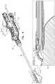
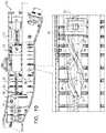
- FIG. 1is a schematic illustration of a surgical tool, including a side-view and top-view of a distal portion of the surgical tool, in accordance with some applications of the present invention
- FIG. 2is a schematic illustration of the surgical tool showing a cross-section of a handle of the surgical tool, and side-views of the surgical tool within a body of a subject, in accordance with some applications of the present invention
- FIG. 3is a schematic illustration of the surgical tool showing a portion of tissue drawn into the surgical tool by suction through the surgical tool, in accordance with some applications of the present invention
- FIG. 4is a schematic illustration of the surgical tool showing a needle puncturing the portion of tissue inside the surgical tool, in accordance with some applications of the present invention
- FIG. 5is a schematic illustration of the surgical tool showing rotation of the needle after puncturing the portion of tissue, in accordance with some applications of the present invention
- FIG. 6is a schematic illustration of the surgical tool showing a guidewire being inserted through the rotated needle, in accordance with some applications of the present invention
- FIG. 7is a schematic illustration of the surgical tool showing the needle being retracted proximally into the surgical tool while in the rotated orientation, in accordance with some applications of the present invention
- FIG. 8is a schematic illustration of the surgical tool showing rotation of the needle again after the proximal retraction, in accordance with some applications of the present invention.
- FIG. 9is a schematic illustration of the surgical tool after the suction through the surgical tool has been terminated, in accordance with some applications of the present invention.
- FIG. 10is a schematic illustration of a cross-section of a handle of the surgical tool, in accordance with some applications of the present invention.
- FIG. 1is a schematic illustration of a surgical tool 20 in accordance with some applications of the present invention.
- Surgical tool 20is designed to be advanced distally within a body of a subject, e.g., toward a heart of a subject, and is shaped to define a side-facing suction port 22 at a distal portion 24 of surgical tool 20 to facilitate drawing tissue 26 , e.g., a portion 27 of the pericardium 28 of a subject (such as is shown in FIG. 3 ) into surgical tool 20 .
- Tissue 26is drawn into surgical tool 20 by applying suction to tissue 26 through side-facing suction port 22 .
- a needle 34is slidably disposed within surgical tool 20 and is used to puncture tissue 26 , e.g., portion 27 of pericardium 28 , by advancing needle 34 distally into side-facing suction port 22 while tissue 26 is inside side-facing suction port 22 .
- side-facing suction port 22has the following dimensions:
- distal portion 24 of surgical tool 20has an outer diameter of at least 8 mm and/or less than 12 mm.
- a slidable transparent shutter 30is disposed over side-facing suction port 22 to help prevent fat and/or tissue from building up inside side-facing suction port 22 as surgical tool 20 is advanced distally within the body.
- Slidable transparent shutter 30can be slidably removed from side-facing suction port 22 once tissue 26 is reached, e.g., once pericardium 28 is reached (such as is shown in FIG. 3 ).
- slidable transparent shutter 30may be slidably removed by sliding the shutter in a proximal direction, thus exposing side-facing suction port 22 .
- use of surgical tool 20includes contacting pericardium 28 with slidable transparent shutter 30 before exposing side-facing suction port 22 (such as is shown in FIG.
- slidable transparent shutter 30is removed by turning a rotational actuator 31 on surgical tool 20 (such as is shown in FIG. 3 ).
- Rotational actuator 31engages threads 33 on a pulling screw 35 , which pulls slidable transparent shutter 30 in a proximal direction thus exposing side-facing suction port 22 .
- a camera 32is positioned in distal portion 24 such that a view from camera 32 is through side-facing suction port 22 .
- the transparency of slidable transparent shutter 30helps to maintain visibility.
- LED lightingmay also be used inside surgical tool 20 to assist visibility through camera 32 .
- surgical tool 20comprises a sensor 102 configured to (a) detect when slidable transparent shutter 30 is disposed over suction port 22 and (b) inhibit application of suction to side-facing suction port 22 when slidable transparent shutter 30 is disposed over side-facing suction port 22 .
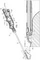
- FIG. 2is a schematic illustration of surgical tool 20 , showing a cross-section of a handle 40 of surgical tool 20 , and side-views of surgical tool 20 within a body of a subject, in accordance with some applications of the present invention.
- Needle 34is a hollow needle shaped to define a slanted puncturing tip 36 .
- needle 34oriented such that an opening 37 at puncturing tip 36 of needle 34 faces away from the myocardium 29 of the subject (such as is shown in FIG. 4 ).
- FIG. 2shows driving assembly 38 and needle 34 in starting position.
- opening 37 at puncturing tip 36 of needle 34faces away from myocardium 29 and is fully inside lumen 46 of surgical tool 20 .
- a user control 48is coupled to driving assembly 38 and is used to activate driving assembly 38 to drive needle 34 within lumen 46 .
- a first activation of user control 48distally advances driving assembly 38 in two distal-mode phases:
- each of the first and second activations of user control 48are executed in single smooth respective motions of user control 48 , i.e., the distal-mode first phase and distal mode second phase are executed in a first single smooth motion of user control 48 and then the proximal-mode first phase and proximal-mode second phase are executed in a second single smooth motion of user control 48 .
- user control 48may be a slide-bar 50 that is coupled to driving assembly 38 . Slide-bar 50 is configured to be advanced distally with respect to handle 40 in order to cause the first activation, and to be retracted proximally with respect to handle 40 in order to cause the second activation.
- distal-mode first phase and distal-mode second phaseare executed in a single smooth distally-directed motion of slide-bar 50 with respect to handle 40
- proximal-mode first phase and proximal-mode second phaseare executed in a single smooth proximally-directed motion of slide-bar 50 with respect to handle 40
- the respective single smooth motions of user control 48e.g., slide-bar 50
- the physiciandoes not have to substantially think about each phase of the needle movement individually.
- FIG. 3is a schematic illustration of surgical tool 20 showing a portion of tissue drawn into surgical tool 20 by suction through surgical tool 20 , in accordance with some applications of the present invention.
- suctionis applied to pericardium 28 through a proximal opening 88 of an external vacuum tube 90 which is disposed within handle 40 of surgical tool 20 .
- Proximal opening 88 of external vacuum tube 90is disposed at a proximal end 52 of handle 40 .
- External vacuum tube 90sealably connects to an internal vacuum tube 92 which is disposed along-side lumen 46 in surgical tool 20 and has a distal opening 94 inside side-facing suction port 22 .
- a vacuum activation user control 54is disposed on handle 40 .
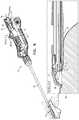
- FIGS. 4-6are schematic illustrations of surgical tool 20 showing the distal-mode phases of motion of needle 34 , in accordance with some applications of the present invention.
- driving assembly 38has a proximal portion 42 and a distal portion 44 that are slidably coupled to each other.
- Needle 34which is slidably disposed within a lumen 46 of surgical tool 20 , is coupled to proximal portion 42 of driving assembly 38 (such as is shown in FIG. 10 ).
- driving assembly 38is advanced distally with respect to handle 40 ( FIG. 4 ).
- needle 34is advanced distally within lumen 46 of surgical tool 20 , thereby puncturing portion 27 of pericardium 28 .
- Needle 34is rotationally stationary with respect to longitudinal axis 56 of surgical tool 20 during the distal-mode first phase.
- distal portion 44 of driving assembly 38is advanced distally with respect to proximal portion 42 of driving assembly 38 ( FIG. 5 ).
- Distal advancement of distal portion 44 of driving assembly 38 with respect to proximal portion 42 of driving assembly 38rotates needle 34 in a first rotational direction about longitudinal axis 56 of surgical tool 20 while puncturing tip 36 of needle 34 is between pericardium 28 and myocardium 29 of the heart.
- the distal-mode second phasetypically rotates needle 34 by 120-240 degrees without further distal advancement of needle 34 .
- proximal portion 42 of the driving assemblyis shaped to define (a) an inner core 62 , and (b) an outer surface 64 surrounding a proximal length L 2 of inner core 62 .
- Outer surface 64is shaped to define a protrusion 66 extending laterally with respect to longitudinal axis 56 of surgical tool 20 .
- Distal portion 44 of driving assembly 38comprises a hollow shaft element 68 which is slidably coupled to proximal portion 42 of driving assembly 38 such that prior to distal advancement of distal portion 44 with respect to proximal portion 42 , a distal length L 3 of inner core 62 is disposed along hollow shaft element 68 , e.g., within hollow shaft element 68 .
- Handle 40 of surgical tool 20is shaped to define at least one protruding stop 70 on an inner wall 72 of handle 40 .
- the first activation of user control 48causes driving assembly 38 to be advanced distally with respect to handle 40 until protrusion 66 engages protruding stop 70 , which locks proximal portion 42 of driving assembly 38 in place, thus marking the end of the distal-mode first phase.
- the remainder of the first activation of user control 48subsequently advances distal portion 44 of driving assembly 38 with respect to proximal portion 42 of driving assembly 38 .
- a mechanical interaction between proximal portion 42 and distal portion 44 of driving assembly 38 during the distal-mode second phasecauses needle 34 to rotate about longitudinal axis 56 .
- proximal portion 42 of driving assembly 38is shaped to define a first thread 74 ( FIG. 10 ) along at least a portion of proximal portion 42 , e.g., along distal length L 3 of inner core 62
- distal portion 44 of driving assembly 38is shaped to define a second thread 76 along at least a portion of distal portion 44 , e.g., on an inside surface of hollow shaft element 68
- Proximal portion 42 and distal portion 44 of driving assembly 38are arranged such that (a) first thread 74 and second thread 76 engage one another (such as is shown in FIG. 10 ), and (b) engagement between first thread 74 and second thread 76 as distal portion 44 of driving assembly 38 is advanced distally with respect to proximal portion 42 of driving assembly rotates needle 34 in the first rotational direction about longitudinal axis 56 .
- proximal portion 42 of driving assembly 38is shaped to define a thread along at least a portion of proximal portion 42 , e.g., along distal length L 3 of inner core 62
- distal portion 44 of driving assembly 38is shaped to define a protrusion (configuration not shown).
- Proximal portion 42 and distal portion 44 of driving assembly 38are arranged such that (a) the protrusion and the thread engage with one another, and (b) engagement between the protrusion and the thread as distal portion 44 of driving assembly 38 is advanced distally with respect to proximal portion 42 of driving assembly 38 rotates needle 34 in the first rotational direction about longitudinal axis 56 .
- proximal portion 42 of driving assembly 38is shaped to define a protrusion
- distal portion 44 of driving assembly 38is shaped to define a thread along at least a portion of distal portion 44 , e.g., on an inside surface of hollow shaft element 68 (configuration not shown).
- Proximal portion 42 and distal portion 44 of driving assembly 38are arranged such that (a) the protrusion and the thread engage with one another, and (b) engagement between the protrusion and the thread as distal portion 44 of driving assembly 38 is advanced distally with respect to proximal portion 42 of driving assembly 38 rotates needle 34 in the first rotational direction about longitudinal axis 56 .
- a guidewire 58is inserted through a guide-wire leading tube 60 , as further described hereinbelow.
- the rotated position of needle 34facilitates easy insertion of guidewire 58 through needle 34 into the pericardial region ( FIG. 6 ).
- fluoroscopyis used to help determine that guidewire 58 is in the pericardial region.
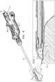
- FIGS. 7-8are schematic illustrations of surgical tool 20 showing the proximal-mode phases of motion of needle 34 , in accordance with some applications of the present invention.
- the second activation of user control 48e.g., the proximally-directed motion of slide-bar 50 , activates the proximal-mode first and second phases.
- driving assembly 38is retracted proximally with respect to handle 40 ( FIG. 7 ), causing needle 34 to be retracted proximally into lumen 46 of surgical tool 20 .
- Needle 34is rotationally stationary with respect to longitudinal axis 56 during proximal-mode first phase.
- distal portion 44 of driving assembly 38is retracted proximally with respect to proximal portion 42 of driving assembly 38 ( FIG. 8 ).
- Proximal retraction of distal portion 44 with respect to proximal portion 42 of driving assembly 38rotates needle 34 in the second rotational direction opposite the first rotational direction about longitudinal axis 56 .
- needle 34is in the same position as it was prior to the distal-mode first phase.
- first thread 74 and second thread 76 as distal portion 44 of driving assembly 38is retracted proximally with respect to proximal portion 42 of driving assembly 38 rotates needle 34 in the second rotational direction about longitudinal axis 56 .
- FIG. 9is a schematic illustration of surgical tool 20 after the suction through surgical tool 20 has been terminated, in accordance with some applications of the present invention.
- FIG. 10is a schematic illustration of a cross-section of handle 40 of surgical tool 20 , in accordance with some applications of the present invention.
- guidewire leading tube 60is disposed in proximal end 52 of handle 40 such that at least a distal end 78 of guidewire leading tube 60 is inside proximal portion 42 of driving assembly 38 .
- Guidewire 58is inserted through guidewire leading tube 60 into proximal portion 42 of driving assembly 38 .
- Proximal portionguides guidewire 58 from guidewire leading tube 60 to a proximal end 80 of needle 34 .
- proximal portion 42may be shaped to define an internal funnel 82 , a wider end 84 of funnel 82 being open to guidewire leading tube 60 , such that guidewire 58 is guided into proximal end 80 of needle 34 by funnel 82 .
- a narrow end 86 of funnel 82is at proximal end 80 of needle 34 .
- a distal gasket 96surrounds needle 34 at a proximal opening 98 of lumen 46 .
- Distal gasket 96provides a seal around needle 34 at proximal opening 98 of lumen 46 , thus preventing premature termination of the vacuum by preventing air from entering side-facing suction port 22 through lumen 46 as needle 34 slides with respect to lumen 46 .
- Needle 34is slidable with respect to distal gasket 96 as well.
- a proximal gasket 100is disposed between proximal portion 42 of driving assembly 38 and guidewire leading tube 60 .
- Proximal gasket 100provides a seal between guidewire leading tube 60 and proximal portion 42 .
- Proximal portion 42 of driving assembly 38 and proximal gasket 100move along the outside of guidewire leading tube 60 during motion of driving assembly with respect to handle 40 of surgical tool 20 .
- surgical tool 20may be used to puncture an outer layer of a stomach, intestine, or brain of a subject. All features of the present invention as described hereinabove apply to applications of surgical tool 20 with anatomy other than the heart.
- puncturing pericardium 28surgical tool is advanced within the body of a subject until slidable transparent shutter 30 comes into contact with the target tissue, stomach, intestine, and/or brain. Slidable transparent shutter 30 is then removed from side-facing suction port 22 and suction is applied to draw a portion of the tissue into side-facing suction port 22 .
- Activation of user control 48drives needle 34 to puncture the tissue and guidewire 58 can be inserted.
Landscapes
- Health & Medical Sciences (AREA)
- Surgery (AREA)
- Life Sciences & Earth Sciences (AREA)
- Medical Informatics (AREA)
- Nuclear Medicine, Radiotherapy & Molecular Imaging (AREA)
- Engineering & Computer Science (AREA)
- Biomedical Technology (AREA)
- Heart & Thoracic Surgery (AREA)
- Pathology (AREA)
- Molecular Biology (AREA)
- Animal Behavior & Ethology (AREA)
- General Health & Medical Sciences (AREA)
- Public Health (AREA)
- Veterinary Medicine (AREA)
- Oral & Maxillofacial Surgery (AREA)
- Surgical Instruments (AREA)
Abstract
Description
- the distal-mode first phase distally advancing a needle into the suction port while the needle is rotationally stationary with respect to a longitudinal axis of the surgical tool, thereby puncturing the portion of the pericardium within the suction port, and
- the distal-mode second phase rotating the needle in a first rotational direction while a puncturing tip of the needle is between the pericardium and myocardium of the heart.
- a width W of at least 2.5 mm and/or less than 4.5 mm,
- a length L1 of at least 8 mm and/or less than 12 mm, such that
needle 34 can extend at least 3 mm and/or less than 7 mm into side-facingsuction port 22, and/or - a depth D1 of at least 3.5 mm and/or less than 6.5 mm.
- a distal-mode first phase, in which needle34 is advanced distally within
lumen 46 while remaining rotationally stationary with respect to alongitudinal axis 56 ofsurgical tool 20, thereby puncturing tissue26 inside side-facingsuction port 22, e.g., puncturingportion 27 of pericardium28 (such as is shown inFIG. 4 ), and - a distal-mode second phase, in which needle34 is rotated in a first rotational direction about
longitudinal axis 56 while puncturing tip36 ofneedle 34 is betweenpericardium 28 andmyocardium 29 of the heart (such as is shown inFIG. 5 ).
A second activation of user control48 proximally retracts drivingassembly 38 in two proximal-mode phases: - a proximal-mode first phase, in which needle34 is proximally retracted into
lumen 46 ofsurgical tool 20 while remaining rotationally stationary with respect tolongitudinal axis 56 of surgical tool20 (such as is shown inFIG. 7 ), and - a proximal-mode second phase, in which needle34 is rotated in a second rotational direction opposite to the fist rotational direction about longitudinal axis56 (such as is shown in
FIG. 8 ).
- a distal-mode first phase, in which needle34 is advanced distally within
- (b) U.S. application Ser. No. 14/704,857 to Gross et al., which published as US 2015-0313634, entitled “Pericardial Access Device,” filed May 5, 2015,
- (c) PCT Application No. PCT/IB2015/053280 to Gross et al., which published as WO/2015/170256, entitled “Pericardial Access Device,” filed May 5, 2015,
- (d) U.S. application Ser. No. 15/338,853 to Gross et al., which published as US 2017-0119435 to Gross, entitled “Pericardial Access Device,” filed Oct. 31, 2016, and
- (e) U.S. application Ser. No. 15/324,429 to Gross et al., which published as US 2017/0196568 to Gross, entitled “Left Atrial Appendage Closure,” filed Jan. 6, 2017.
Claims (21)
Priority Applications (1)
| Application Number | Priority Date | Filing Date | Title |
|---|---|---|---|
| US15/821,973US10667842B2 (en) | 2017-11-24 | 2017-11-24 | Pericardial needle mechanism |
Applications Claiming Priority (1)
| Application Number | Priority Date | Filing Date | Title |
|---|---|---|---|
| US15/821,973US10667842B2 (en) | 2017-11-24 | 2017-11-24 | Pericardial needle mechanism |
Publications (2)
| Publication Number | Publication Date |
|---|---|
| US20190159808A1 US20190159808A1 (en) | 2019-05-30 |
| US10667842B2true US10667842B2 (en) | 2020-06-02 |
Family
ID=66634152
Family Applications (1)
| Application Number | Title | Priority Date | Filing Date |
|---|---|---|---|
| US15/821,973Active2038-07-20US10667842B2 (en) | 2017-11-24 | 2017-11-24 | Pericardial needle mechanism |
Country Status (1)
| Country | Link |
|---|---|
| US (1) | US10667842B2 (en) |
Families Citing this family (3)
| Publication number | Priority date | Publication date | Assignee | Title |
|---|---|---|---|---|
| CN112120742B (en)* | 2019-06-25 | 2025-06-13 | 杭州德柯医疗科技有限公司 | Piercing device |
| CN116407159A (en)* | 2021-12-29 | 2023-07-11 | 深圳市先健呼吸科技有限公司 | Biopsy device |
| WO2025129088A1 (en)* | 2023-12-15 | 2025-06-19 | Atricure, Inc. | Devices and methods for epicardial access |
Citations (71)
| Publication number | Priority date | Publication date | Assignee | Title |
|---|---|---|---|---|
| US5309896A (en) | 1991-05-29 | 1994-05-10 | Origin Medsystems, Inc. | Retraction methods using endoscopic inflatable retraction devices |
| US5335671A (en) | 1989-11-06 | 1994-08-09 | Mectra Labs, Inc. | Tissue removal assembly with provision for an electro-cautery device |
| US5336252A (en) | 1992-06-22 | 1994-08-09 | Cohen Donald M | System and method for implanting cardiac electrical leads |
| US5458112A (en) | 1994-08-15 | 1995-10-17 | Arrow Precision Products, Inc. | Biliary biopsy device |
| US5478309A (en) | 1994-05-27 | 1995-12-26 | William P. Sweezer, Jr. | Catheter system and method for providing cardiopulmonary bypass pump support during heart surgery |
| WO1996000038A1 (en) | 1994-06-23 | 1996-01-04 | Cormedics Corp. | Intrapericardial space drug delivery apparatus and method |
| US5584803A (en) | 1991-07-16 | 1996-12-17 | Heartport, Inc. | System for cardiac procedures |
| WO1996040368A1 (en) | 1995-06-07 | 1996-12-19 | Cormedics Corp. | Method and apparatus for accessing the pericardial space |
| US5792153A (en) | 1994-03-23 | 1998-08-11 | University College London | Sewing device |
| JPH11123197A (en) | 1997-10-23 | 1999-05-11 | Olympus Optical Co Ltd | Sucking biopsy tool |
| WO1999023812A2 (en) | 1997-11-04 | 1999-05-14 | Sightline Technologies Ltd. | Video rectoscope |
| WO1999059663A1 (en) | 1998-05-16 | 1999-11-25 | Microheart, Inc. | Drug delivery module |
| US6004269A (en) | 1993-07-01 | 1999-12-21 | Boston Scientific Corporation | Catheters for imaging, sensing electrical potentials, and ablating tissue |
| US6083166A (en) | 1997-12-02 | 2000-07-04 | Situs Corporation | Method and apparatus for determining a measure of tissue manipulation |
| US6210323B1 (en) | 1998-05-05 | 2001-04-03 | The University Of British Columbia | Surgical arm and tissue stabilizer |
| US6216704B1 (en) | 1997-08-13 | 2001-04-17 | Surx, Inc. | Noninvasive devices, methods, and systems for shrinking of tissues |
| US6231518B1 (en)* | 1998-05-26 | 2001-05-15 | Comedicus Incorporated | Intrapericardial electrophysiological procedures |
| US20010041821A1 (en) | 1993-06-17 | 2001-11-15 | Wilk Peter J. | Intrapericardial assist method |
| DE10126062A1 (en) | 2000-05-26 | 2001-12-13 | Olympus Optical Co | Hood for endoscope has flexible tube into which endoscopic treatment instrument can be inserted with opening at distal end for connecting to hollow chamber of cap part |
| US20020002371A1 (en) | 2000-03-24 | 2002-01-03 | Acker David E. | Apparatus and methods for intrabody thermal treatment |
| US6398795B1 (en) | 2000-11-30 | 2002-06-04 | Scimed Life Systems, Inc. | Stapling and cutting in resectioning for full thickness resection devices |
| US6463332B1 (en) | 1999-09-17 | 2002-10-08 | Core Medical, Inc. | Method and system for pericardial enhancement |
| US20030074057A1 (en) | 2001-10-12 | 2003-04-17 | Rosengart Todd K. | Method and apparatus for performing an anastamosis |
| US6575969B1 (en) | 1995-05-04 | 2003-06-10 | Sherwood Services Ag | Cool-tip radiofrequency thermosurgery electrode system for tumor ablation |
| US20030187460A1 (en) | 1999-08-10 | 2003-10-02 | Chin Albert K. | Methods and apparatus for endoscopic cardiac surgery |
| US6632227B2 (en) | 2001-08-24 | 2003-10-14 | Scimed Life Systems, Inc. | Endoscopic resection devices |
| US6695764B2 (en) | 1999-08-13 | 2004-02-24 | Scimed Life Systems, Inc. | Apparatus for treating wall of body cavity |
| US6721663B1 (en) | 1999-11-19 | 2004-04-13 | Proteom Limited | Method for manipulating protein or DNA sequence data in order to generate complementary peptide ligands |
| US20040087831A1 (en) | 2002-10-31 | 2004-05-06 | Koen Michels | Anatomical space access tools and methods |
| US20040098030A1 (en) | 1996-02-02 | 2004-05-20 | Trans Vascular, Inc. | Methods and apparatus for blocking flow through blood vessels |
| US20040216748A1 (en) | 1999-08-10 | 2004-11-04 | Chin Albert K. | Apparatus and method for endoscopic encirclement of pulmonary veins for epicardial ablation |
| US6837848B2 (en) | 2003-01-15 | 2005-01-04 | Medtronic, Inc. | Methods and apparatus for accessing and stabilizing an area of the heart |
| EP1518498A1 (en) | 2003-09-29 | 2005-03-30 | Ethicon Endo-Surgery, Inc. | Endoscopic mucosal resection device |
| US6908427B2 (en) | 2002-12-30 | 2005-06-21 | PARÉ Surgical, Inc. | Flexible endoscope capsule |
| US20060079868A1 (en) | 2004-10-07 | 2006-04-13 | Guided Therapy Systems, L.L.C. | Method and system for treatment of blood vessel disorders |
| US20060189840A1 (en) | 2005-02-18 | 2006-08-24 | Acorn Cardiovascular, Inc. | Transmyocardial delivery of cardiac wall tension relief |
| US20070004984A1 (en) | 1997-10-31 | 2007-01-04 | University Of Washington | Method and apparatus for preparing organs and tissues for laparoscopic surgery |
| US20070010793A1 (en) | 2005-06-23 | 2007-01-11 | Cardiac Pacemakers, Inc. | Method and system for accessing a pericardial space |
| US20070129719A1 (en) | 2005-05-26 | 2007-06-07 | Amar Kendale | Apparatus and methods for performing minimally-invasive surgical procedures |
| WO2007127664A1 (en) | 2006-04-28 | 2007-11-08 | Medtronic, Inc. | Methods and devices for occlusion of an atrial appendage |
| US20070265610A1 (en) | 2006-05-12 | 2007-11-15 | Thapliyal Hira V | Device for Ablating Body Tissue |
| US20080071289A1 (en) | 2006-06-13 | 2008-03-20 | Intuitive Surgical, Inc. | Side looking minimally invasive surgery instrument assembly |
| DE102006058447A1 (en) | 2006-12-10 | 2008-06-19 | Philipps-Universität Marburg | Device for fixation and manipulation of organic or inorganic tissues |
| US20080243162A1 (en) | 2007-04-02 | 2008-10-02 | Norikiyo Shibata | Trocar |
| US20080312664A1 (en) | 2007-05-21 | 2008-12-18 | Epitek, Inc. | Left atrial appendage closure |
| US20090048514A1 (en) | 2006-03-09 | 2009-02-19 | Slender Medical Ltd. | Device for ultrasound monitored tissue treatment |
| US20090209986A1 (en) | 2008-02-15 | 2009-08-20 | Stewart Michael C | Devices, Tools and Methods for Atrial Appendage Exclusion |
| US20100057108A1 (en)* | 2008-09-02 | 2010-03-04 | Ethicon Endo-Surgery, Inc. | Suturing device |
| US20100125281A1 (en) | 2008-11-17 | 2010-05-20 | Northwestern University | Cardiac pacing lead and delivery sheath |
| US20100217151A1 (en) | 2007-07-11 | 2010-08-26 | Zach Gostout | Methods and Systems for Performing Submucosal Medical Procedures |
| US20110009853A1 (en) | 2001-12-04 | 2011-01-13 | Bertolero Arthur A | Left atrial appendage devices and methods |
| US20110028998A1 (en)* | 2009-01-26 | 2011-02-03 | Synthes Usa, Llc | Bi-directional suture passer |
| JP2011177597A (en) | 2011-06-24 | 2011-09-15 | Fujifilm Corp | Ultrasonic endoscope |
| US20110251524A1 (en) | 2006-03-09 | 2011-10-13 | Slender Medical, Ltd. | Device for ultrasound treatment and monitoring tissue treatment |
| WO2011130456A1 (en) | 2010-04-13 | 2011-10-20 | Sentreheart, Inc. | Methods and devices for pericardial access |
| US20110270239A1 (en) | 2010-04-29 | 2011-11-03 | Werneth Randell L | Transseptal crossing device |
| US20110282203A1 (en) | 2010-05-14 | 2011-11-17 | Liat Tsoref | Reflectance-facilitated ultrasound treatment and monitoring |
| US20110282249A1 (en) | 2010-05-14 | 2011-11-17 | Liat Tsoref | Reflectance-facilitated ultrasound treatment |
| US20120088964A1 (en) | 2010-10-11 | 2012-04-12 | Epicardial Technologies, Inc. | Methods and devices for pericardial access |
| US20120116158A1 (en) | 2008-07-08 | 2012-05-10 | Hale Eric L | Wide Angle Flexible Endoscope |
| US20130103028A1 (en) | 2010-05-14 | 2013-04-25 | Liat Tsoref | Reflectance-facilitated ultrasound treatment and monitoring |
| WO2013121424A2 (en) | 2012-02-14 | 2013-08-22 | Rainbow Medical Ltd. | Reflectance-facilitated ultrasound treatment and monitoring |
| US8602973B2 (en) | 2000-01-27 | 2013-12-10 | Boston Scientific Scimed, Inc. | Catheter introducer system for exploration of body cavities |
| US20130338545A1 (en) | 2010-12-14 | 2013-12-19 | Slender Medical Ltd. | Ultrasound skin treatment |
| US20140012083A1 (en) | 2012-07-05 | 2014-01-09 | Pavilion Medical Innovations, Llc | Endoscopic Cannulas and Methods of Using the Same |
| WO2014015259A1 (en) | 2012-07-19 | 2014-01-23 | Creighton University | Tissue resection device and method |
| US20150133946A1 (en)* | 2013-11-14 | 2015-05-14 | Aquesys, Inc. | Intraocular shunt inserter |
| US20150182275A1 (en) | 2013-12-30 | 2015-07-02 | Rainbow Medical Ltd. | Reflectance-facilitated ultrasound treatment |
| US20150313634A1 (en) | 2014-05-05 | 2015-11-05 | Rainbow Medical Ltd. | Pericardial access device |
| US20150313633A1 (en) | 2014-05-05 | 2015-11-05 | Rainbow Medical Ltd. | Pericardial access device |
| US20150359558A1 (en) | 2012-02-14 | 2015-12-17 | Rainbow Medical Ltd. | Reflectance-facilitated ultrasound treatment and monitoring |
- 2017
- 2017-11-24USUS15/821,973patent/US10667842B2/enactiveActive
Patent Citations (87)
| Publication number | Priority date | Publication date | Assignee | Title |
|---|---|---|---|---|
| US5335671A (en) | 1989-11-06 | 1994-08-09 | Mectra Labs, Inc. | Tissue removal assembly with provision for an electro-cautery device |
| US5309896A (en) | 1991-05-29 | 1994-05-10 | Origin Medsystems, Inc. | Retraction methods using endoscopic inflatable retraction devices |
| US5584803A (en) | 1991-07-16 | 1996-12-17 | Heartport, Inc. | System for cardiac procedures |
| US5336252A (en) | 1992-06-22 | 1994-08-09 | Cohen Donald M | System and method for implanting cardiac electrical leads |
| US20010041821A1 (en) | 1993-06-17 | 2001-11-15 | Wilk Peter J. | Intrapericardial assist method |
| US6004269A (en) | 1993-07-01 | 1999-12-21 | Boston Scientific Corporation | Catheters for imaging, sensing electrical potentials, and ablating tissue |
| US5792153A (en) | 1994-03-23 | 1998-08-11 | University College London | Sewing device |
| US5478309A (en) | 1994-05-27 | 1995-12-26 | William P. Sweezer, Jr. | Catheter system and method for providing cardiopulmonary bypass pump support during heart surgery |
| WO1996000038A1 (en) | 1994-06-23 | 1996-01-04 | Cormedics Corp. | Intrapericardial space drug delivery apparatus and method |
| US5634895A (en) | 1994-06-23 | 1997-06-03 | Cormedics Corp. | Apparatus and method for transpericardial delivery of fluid |
| US5458112A (en) | 1994-08-15 | 1995-10-17 | Arrow Precision Products, Inc. | Biliary biopsy device |
| US6575969B1 (en) | 1995-05-04 | 2003-06-10 | Sherwood Services Ag | Cool-tip radiofrequency thermosurgery electrode system for tumor ablation |
| US5827216A (en) | 1995-06-07 | 1998-10-27 | Cormedics Corp. | Method and apparatus for accessing the pericardial space |
| US6162195A (en) | 1995-06-07 | 2000-12-19 | Cormedics Corp. | Method and apparatus for accessing the pericardial space |
| WO1996040368A1 (en) | 1995-06-07 | 1996-12-19 | Cormedics Corp. | Method and apparatus for accessing the pericardial space |
| US20040098030A1 (en) | 1996-02-02 | 2004-05-20 | Trans Vascular, Inc. | Methods and apparatus for blocking flow through blood vessels |
| US6216704B1 (en) | 1997-08-13 | 2001-04-17 | Surx, Inc. | Noninvasive devices, methods, and systems for shrinking of tissues |
| JPH11123197A (en) | 1997-10-23 | 1999-05-11 | Olympus Optical Co Ltd | Sucking biopsy tool |
| US20070004984A1 (en) | 1997-10-31 | 2007-01-04 | University Of Washington | Method and apparatus for preparing organs and tissues for laparoscopic surgery |
| WO1999023812A2 (en) | 1997-11-04 | 1999-05-14 | Sightline Technologies Ltd. | Video rectoscope |
| US6083166A (en) | 1997-12-02 | 2000-07-04 | Situs Corporation | Method and apparatus for determining a measure of tissue manipulation |
| US6210323B1 (en) | 1998-05-05 | 2001-04-03 | The University Of British Columbia | Surgical arm and tissue stabilizer |
| WO1999059663A1 (en) | 1998-05-16 | 1999-11-25 | Microheart, Inc. | Drug delivery module |
| US6231518B1 (en)* | 1998-05-26 | 2001-05-15 | Comedicus Incorporated | Intrapericardial electrophysiological procedures |
| US20040216748A1 (en) | 1999-08-10 | 2004-11-04 | Chin Albert K. | Apparatus and method for endoscopic encirclement of pulmonary veins for epicardial ablation |
| US20030187460A1 (en) | 1999-08-10 | 2003-10-02 | Chin Albert K. | Methods and apparatus for endoscopic cardiac surgery |
| US6695764B2 (en) | 1999-08-13 | 2004-02-24 | Scimed Life Systems, Inc. | Apparatus for treating wall of body cavity |
| US6463332B1 (en) | 1999-09-17 | 2002-10-08 | Core Medical, Inc. | Method and system for pericardial enhancement |
| US6721663B1 (en) | 1999-11-19 | 2004-04-13 | Proteom Limited | Method for manipulating protein or DNA sequence data in order to generate complementary peptide ligands |
| US8602973B2 (en) | 2000-01-27 | 2013-12-10 | Boston Scientific Scimed, Inc. | Catheter introducer system for exploration of body cavities |
| US20020002371A1 (en) | 2000-03-24 | 2002-01-03 | Acker David E. | Apparatus and methods for intrabody thermal treatment |
| US20010053909A1 (en) | 2000-05-26 | 2001-12-20 | Olympus Optical Co., Ltd. | Endoscope hood for mucous membrane resection |
| DE10126062A1 (en) | 2000-05-26 | 2001-12-13 | Olympus Optical Co | Hood for endoscope has flexible tube into which endoscopic treatment instrument can be inserted with opening at distal end for connecting to hollow chamber of cap part |
| US6398795B1 (en) | 2000-11-30 | 2002-06-04 | Scimed Life Systems, Inc. | Stapling and cutting in resectioning for full thickness resection devices |
| US6632227B2 (en) | 2001-08-24 | 2003-10-14 | Scimed Life Systems, Inc. | Endoscopic resection devices |
| US20030074057A1 (en) | 2001-10-12 | 2003-04-17 | Rosengart Todd K. | Method and apparatus for performing an anastamosis |
| US20110009853A1 (en) | 2001-12-04 | 2011-01-13 | Bertolero Arthur A | Left atrial appendage devices and methods |
| US20040087831A1 (en) | 2002-10-31 | 2004-05-06 | Koen Michels | Anatomical space access tools and methods |
| US6908427B2 (en) | 2002-12-30 | 2005-06-21 | PARÉ Surgical, Inc. | Flexible endoscope capsule |
| US6837848B2 (en) | 2003-01-15 | 2005-01-04 | Medtronic, Inc. | Methods and apparatus for accessing and stabilizing an area of the heart |
| US7186252B2 (en) | 2003-09-29 | 2007-03-06 | Ethicon Endo-Surgery, Inc. | Endoscopic mucosal resection device and method of use |
| EP1518498A1 (en) | 2003-09-29 | 2005-03-30 | Ethicon Endo-Surgery, Inc. | Endoscopic mucosal resection device |
| CN1628615A (en) | 2003-09-29 | 2005-06-22 | 伊西康内外科公司 | Endoscopic mucosal resection device and usage |
| US20060079868A1 (en) | 2004-10-07 | 2006-04-13 | Guided Therapy Systems, L.L.C. | Method and system for treatment of blood vessel disorders |
| US20060189840A1 (en) | 2005-02-18 | 2006-08-24 | Acorn Cardiovascular, Inc. | Transmyocardial delivery of cardiac wall tension relief |
| US20070129719A1 (en) | 2005-05-26 | 2007-06-07 | Amar Kendale | Apparatus and methods for performing minimally-invasive surgical procedures |
| US20070010793A1 (en) | 2005-06-23 | 2007-01-11 | Cardiac Pacemakers, Inc. | Method and system for accessing a pericardial space |
| US20090048514A1 (en) | 2006-03-09 | 2009-02-19 | Slender Medical Ltd. | Device for ultrasound monitored tissue treatment |
| US20110251524A1 (en) | 2006-03-09 | 2011-10-13 | Slender Medical, Ltd. | Device for ultrasound treatment and monitoring tissue treatment |
| WO2007127664A1 (en) | 2006-04-28 | 2007-11-08 | Medtronic, Inc. | Methods and devices for occlusion of an atrial appendage |
| US20070265610A1 (en) | 2006-05-12 | 2007-11-15 | Thapliyal Hira V | Device for Ablating Body Tissue |
| US20080071289A1 (en) | 2006-06-13 | 2008-03-20 | Intuitive Surgical, Inc. | Side looking minimally invasive surgery instrument assembly |
| DE102006058447A1 (en) | 2006-12-10 | 2008-06-19 | Philipps-Universität Marburg | Device for fixation and manipulation of organic or inorganic tissues |
| US20080243162A1 (en) | 2007-04-02 | 2008-10-02 | Norikiyo Shibata | Trocar |
| US20080312664A1 (en) | 2007-05-21 | 2008-12-18 | Epitek, Inc. | Left atrial appendage closure |
| US20100217151A1 (en) | 2007-07-11 | 2010-08-26 | Zach Gostout | Methods and Systems for Performing Submucosal Medical Procedures |
| US20090209986A1 (en) | 2008-02-15 | 2009-08-20 | Stewart Michael C | Devices, Tools and Methods for Atrial Appendage Exclusion |
| US20120116158A1 (en) | 2008-07-08 | 2012-05-10 | Hale Eric L | Wide Angle Flexible Endoscope |
| US20100057108A1 (en)* | 2008-09-02 | 2010-03-04 | Ethicon Endo-Surgery, Inc. | Suturing device |
| US20100125281A1 (en) | 2008-11-17 | 2010-05-20 | Northwestern University | Cardiac pacing lead and delivery sheath |
| US20110028998A1 (en)* | 2009-01-26 | 2011-02-03 | Synthes Usa, Llc | Bi-directional suture passer |
| WO2011130456A1 (en) | 2010-04-13 | 2011-10-20 | Sentreheart, Inc. | Methods and devices for pericardial access |
| US20110270239A1 (en) | 2010-04-29 | 2011-11-03 | Werneth Randell L | Transseptal crossing device |
| WO2011141918A2 (en) | 2010-05-14 | 2011-11-17 | Liat Tsoref | Reflectance-facilitated ultrasound treatment and monitoring |
| US20150119713A1 (en) | 2010-05-14 | 2015-04-30 | Rainbow Medical Ltd. | Reflectance-facilitated ultrasound treatment and monitoring |
| US20110282203A1 (en) | 2010-05-14 | 2011-11-17 | Liat Tsoref | Reflectance-facilitated ultrasound treatment and monitoring |
| US20130103028A1 (en) | 2010-05-14 | 2013-04-25 | Liat Tsoref | Reflectance-facilitated ultrasound treatment and monitoring |
| US9795450B2 (en) | 2010-05-14 | 2017-10-24 | Rainbow Medical Ltd. | Reflectance-facilitated ultrasound treatment and monitoring |
| US20110282249A1 (en) | 2010-05-14 | 2011-11-17 | Liat Tsoref | Reflectance-facilitated ultrasound treatment |
| US8617150B2 (en) | 2010-05-14 | 2013-12-31 | Liat Tsoref | Reflectance-facilitated ultrasound treatment |
| US20160107003A1 (en) | 2010-05-14 | 2016-04-21 | Liat Tsoref | Reflectance-facilitated ultrasound treatment and monitoring |
| US9242122B2 (en) | 2010-05-14 | 2016-01-26 | Liat Tsoref | Reflectance-facilitated ultrasound treatment and monitoring |
| US8956346B2 (en) | 2010-05-14 | 2015-02-17 | Rainbow Medical, Ltd. | Reflectance-facilitated ultrasound treatment and monitoring |
| US20120088964A1 (en) | 2010-10-11 | 2012-04-12 | Epicardial Technologies, Inc. | Methods and devices for pericardial access |
| US20130338545A1 (en) | 2010-12-14 | 2013-12-19 | Slender Medical Ltd. | Ultrasound skin treatment |
| JP2011177597A (en) | 2011-06-24 | 2011-09-15 | Fujifilm Corp | Ultrasonic endoscope |
| US20150165244A1 (en) | 2012-02-14 | 2015-06-18 | Rainbow Medical Ltd. | Reflectance-facilitated ultrasound treatment and monitoring |
| US20150359558A1 (en) | 2012-02-14 | 2015-12-17 | Rainbow Medical Ltd. | Reflectance-facilitated ultrasound treatment and monitoring |
| US9707414B2 (en) | 2012-02-14 | 2017-07-18 | Rainbow Medical Ltd. | Reflectance-facilitated ultrasound treatment and monitoring |
| WO2013121424A2 (en) | 2012-02-14 | 2013-08-22 | Rainbow Medical Ltd. | Reflectance-facilitated ultrasound treatment and monitoring |
| US20140012083A1 (en) | 2012-07-05 | 2014-01-09 | Pavilion Medical Innovations, Llc | Endoscopic Cannulas and Methods of Using the Same |
| WO2014015259A1 (en) | 2012-07-19 | 2014-01-23 | Creighton University | Tissue resection device and method |
| US20150133946A1 (en)* | 2013-11-14 | 2015-05-14 | Aquesys, Inc. | Intraocular shunt inserter |
| US20150182275A1 (en) | 2013-12-30 | 2015-07-02 | Rainbow Medical Ltd. | Reflectance-facilitated ultrasound treatment |
| US20150313634A1 (en) | 2014-05-05 | 2015-11-05 | Rainbow Medical Ltd. | Pericardial access device |
| US20150313633A1 (en) | 2014-05-05 | 2015-11-05 | Rainbow Medical Ltd. | Pericardial access device |
| WO2015170256A2 (en) | 2014-05-05 | 2015-11-12 | Rainbow Medical Ltd | Pericardial access device |
Non-Patent Citations (19)
| Title |
|---|
| A Written Opinion dated Nov. 9, 2015, which issued during the prosecution of Applicant's PCT/IB2015/053280. |
| An International Preliminary Report on Patentability dated Nov. 8, 2016, which issued during the prosecution of Applicant's PCT/IB2015/053280. |
| An International Search Report and a Written Opinion both dated Sep. 18, 2015, which issued during the prosecution of Applicant's PCT/IB2015/055132. |
| An International Search Report dated Nov. 9, 2015, which issued during the prosecution of Applicant's PCT/IB2015/053280. |
| An Invitation to pay additional fees dated Jul. 28, 2015, which issued during the prosecution of Applicant's PCT/IB2015/053280. |
| An Office Action dated Feb. 24, 2017, which issued during the prosecution of U.S. Appl. No. 14/324,457. |
| An Office Action dated Jul. 23, 2018, which issued during the prosecution of U.S. Appl. No. 14/704,857. |
| An Office Action dated Jul. 27, 2017, which issued during the prosecution of U.S. Appl. No. 14/324,457. |
| An Office Action dated Mar. 15, 2018, which issued during the prosecution of U.S. Appl. No. 14/704,857. |
| An Office Action dated Mar. 22, 2018, which issued during the prosecution of U.S. Appl. No. 14/324,457. |
| An Office Action dated May 8, 2014, which issued during the prosecution of U.S. Appl. No. 13/015,951. |
| An Office Action dated Sep. 22, 2017, which issued during the prosecution of U.S. Appl. No. 14/704,857. |
| An Office Action together with the English translation dated Sep. 19, 2018, which issued during the prosecution of Chinese Patent Application No. 201580036627.5. |
| Communication dated Nov. 28, 2018, from United States Patent and Trademark Office in U.S. Appl. No. 15/338,853. |
| European Search Opinion dated Oct. 8, 2015, which issued during the prosecution of Applicant's European App No. 13749108. |
| Mi-eye product brochure. Trice Medical. 5pgs. Total. |
| U.S. Appl. No. 61/988,457, filed May 5, 2014. |
| U.S. Appl. No. 62/021,327, filed Jul. 7, 2014. |
| U.S. Appl. No. 62/250,787, filed Nov. 4, 2015. |
Also Published As
| Publication number | Publication date |
|---|---|
| US20190159808A1 (en) | 2019-05-30 |
Similar Documents
| Publication | Publication Date | Title |
|---|---|---|
| US12336729B2 (en) | Tissue engagement devices, systems, and methods | |
| JP7016260B2 (en) | Insertion devices and systems that insert medical tools into the patient's body | |
| JP4180382B2 (en) | Tissue separation assembly and tissue separation method | |
| JP3890589B2 (en) | Intracardiac suture device | |
| JP2022133290A (en) | Access device and method for treatment of medical conditions and delivery of injectables | |
| US10667842B2 (en) | Pericardial needle mechanism | |
| US20060253144A1 (en) | Anastomosis instrument and method of excising wall portion of hollow organ within a living body | |
| CN103200878A (en) | Endoscopic ultrasound fine needle aspiration device | |
| CA3111301C (en) | Stone extraction basket and double lumen end cap for stone extraction basket | |
| JP2013509255A (en) | Apparatus and method for performing full thickness tissue biopsy | |
| JP2025109714A (en) | Pericardial access | |
| CN118593089A (en) | Remote intracardiac adjustable curved sheath tube device and system | |
| CN115804631A (en) | Ultrasound imaging catheter with septal needle | |
| TWI882831B (en) | Endoscopic cannula set | |
| CN113208708A (en) | Percutaneous intervention kit and use method | |
| CN111466972B (en) | Suture implantation device and suture | |
| WO2010042807A2 (en) | Method and apparatus for performing minimally invasive biopsy of heart tissue through the sub-xiphoid | |
| US20250057562A1 (en) | Pericardial transection device with retractable cutting apparatus | |
| US20230355337A1 (en) | Endoscope adapter and auxiliary instrument for endoscopic surgery | |
| EP3138503A1 (en) | Needle and stylet management device | |
| US20220039822A1 (en) | Dilating incision device | |
| IL270946B1 (en) | Pericardium catheter including camera for guiding cutting through pericardium | |
| WO2025204561A1 (en) | Medical device system and method for using medical device system | |
| CN115444524A (en) | Puncture outfit and surgical robot system | |
| CN115068115A (en) | Mechanical arm assembly and endoscopic surgery auxiliary instrument |
Legal Events
| Date | Code | Title | Description |
|---|---|---|---|
| FEPP | Fee payment procedure | Free format text:ENTITY STATUS SET TO UNDISCOUNTED (ORIGINAL EVENT CODE: BIG.); ENTITY STATUS OF PATENT OWNER: SMALL ENTITY | |
| FEPP | Fee payment procedure | Free format text:ENTITY STATUS SET TO SMALL (ORIGINAL EVENT CODE: SMAL); ENTITY STATUS OF PATENT OWNER: SMALL ENTITY | |
| STPP | Information on status: patent application and granting procedure in general | Free format text:DOCKETED NEW CASE - READY FOR EXAMINATION | |
| STPP | Information on status: patent application and granting procedure in general | Free format text:NON FINAL ACTION MAILED | |
| STPP | Information on status: patent application and granting procedure in general | Free format text:RESPONSE TO NON-FINAL OFFICE ACTION ENTERED AND FORWARDED TO EXAMINER | |
| STPP | Information on status: patent application and granting procedure in general | Free format text:NOTICE OF ALLOWANCE MAILED -- APPLICATION RECEIVED IN OFFICE OF PUBLICATIONS | |
| AS | Assignment | Owner name:RAINBOW MEDICAL LTD., ISRAEL Free format text:ASSIGNMENT OF ASSIGNORS INTEREST;ASSIGNORS:FOSTICK, GIDEON;UCHITEL, ILAN;VENISLAVSKI, EVGENI;AND OTHERS;SIGNING DATES FROM 20191027 TO 20191104;REEL/FRAME:051921/0186 | |
| STPP | Information on status: patent application and granting procedure in general | Free format text:PUBLICATIONS -- ISSUE FEE PAYMENT VERIFIED | |
| STCF | Information on status: patent grant | Free format text:PATENTED CASE | |
| FEPP | Fee payment procedure | Free format text:MAINTENANCE FEE REMINDER MAILED (ORIGINAL EVENT CODE: REM.); ENTITY STATUS OF PATENT OWNER: SMALL ENTITY | |
| FEPP | Fee payment procedure | Free format text:SURCHARGE FOR LATE PAYMENT, SMALL ENTITY (ORIGINAL EVENT CODE: M2554); ENTITY STATUS OF PATENT OWNER: SMALL ENTITY | |
| MAFP | Maintenance fee payment | Free format text:PAYMENT OF MAINTENANCE FEE, 4TH YR, SMALL ENTITY (ORIGINAL EVENT CODE: M2551); ENTITY STATUS OF PATENT OWNER: SMALL ENTITY Year of fee payment:4 |