US10665919B2 - Antenna pane - Google Patents
Antenna paneDownload PDFInfo
- Publication number
- US10665919B2 US10665919B2US15/555,069US201615555069AUS10665919B2US 10665919 B2US10665919 B2US 10665919B2US 201615555069 AUS201615555069 AUS 201615555069AUS 10665919 B2US10665919 B2US 10665919B2
- Authority
- US
- United States
- Prior art keywords
- antenna
- pane
- base plate
- electrically conductive
- pane according
- Prior art date
- Legal status (The legal status is an assumption and is not a legal conclusion. Google has not performed a legal analysis and makes no representation as to the accuracy of the status listed.)
- Active, expires
Links
Images


Classifications
- H—ELECTRICITY
- H01—ELECTRIC ELEMENTS
- H01Q—ANTENNAS, i.e. RADIO AERIALS
- H01Q1/00—Details of, or arrangements associated with, antennas
- H01Q1/12—Supports; Mounting means
- H01Q1/1271—Supports; Mounting means for mounting on windscreens
- B—PERFORMING OPERATIONS; TRANSPORTING
- B32—LAYERED PRODUCTS
- B32B—LAYERED PRODUCTS, i.e. PRODUCTS BUILT-UP OF STRATA OF FLAT OR NON-FLAT, e.g. CELLULAR OR HONEYCOMB, FORM
- B32B17/00—Layered products essentially comprising sheet glass, or glass, slag, or like fibres
- B32B17/06—Layered products essentially comprising sheet glass, or glass, slag, or like fibres comprising glass as the main or only constituent of a layer, next to another layer of a specific material
- B32B17/10—Layered products essentially comprising sheet glass, or glass, slag, or like fibres comprising glass as the main or only constituent of a layer, next to another layer of a specific material of synthetic resin
- B32B17/10005—Layered products essentially comprising sheet glass, or glass, slag, or like fibres comprising glass as the main or only constituent of a layer, next to another layer of a specific material of synthetic resin laminated safety glass or glazing
- B32B17/10009—Layered products essentially comprising sheet glass, or glass, slag, or like fibres comprising glass as the main or only constituent of a layer, next to another layer of a specific material of synthetic resin laminated safety glass or glazing characterized by the number, the constitution or treatment of glass sheets
- B32B17/10036—Layered products essentially comprising sheet glass, or glass, slag, or like fibres comprising glass as the main or only constituent of a layer, next to another layer of a specific material of synthetic resin laminated safety glass or glazing characterized by the number, the constitution or treatment of glass sheets comprising two outer glass sheets
- B—PERFORMING OPERATIONS; TRANSPORTING
- B32—LAYERED PRODUCTS
- B32B—LAYERED PRODUCTS, i.e. PRODUCTS BUILT-UP OF STRATA OF FLAT OR NON-FLAT, e.g. CELLULAR OR HONEYCOMB, FORM
- B32B17/00—Layered products essentially comprising sheet glass, or glass, slag, or like fibres
- B32B17/06—Layered products essentially comprising sheet glass, or glass, slag, or like fibres comprising glass as the main or only constituent of a layer, next to another layer of a specific material
- B32B17/10—Layered products essentially comprising sheet glass, or glass, slag, or like fibres comprising glass as the main or only constituent of a layer, next to another layer of a specific material of synthetic resin
- B32B17/10005—Layered products essentially comprising sheet glass, or glass, slag, or like fibres comprising glass as the main or only constituent of a layer, next to another layer of a specific material of synthetic resin laminated safety glass or glazing
- B32B17/10165—Functional features of the laminated safety glass or glazing
- B32B17/10174—Coatings of a metallic or dielectric material on a constituent layer of glass or polymer
- B32B17/10183—Coatings of a metallic or dielectric material on a constituent layer of glass or polymer being not continuous, e.g. in edge regions
- B—PERFORMING OPERATIONS; TRANSPORTING
- B32—LAYERED PRODUCTS
- B32B—LAYERED PRODUCTS, i.e. PRODUCTS BUILT-UP OF STRATA OF FLAT OR NON-FLAT, e.g. CELLULAR OR HONEYCOMB, FORM
- B32B17/00—Layered products essentially comprising sheet glass, or glass, slag, or like fibres
- B32B17/06—Layered products essentially comprising sheet glass, or glass, slag, or like fibres comprising glass as the main or only constituent of a layer, next to another layer of a specific material
- B32B17/10—Layered products essentially comprising sheet glass, or glass, slag, or like fibres comprising glass as the main or only constituent of a layer, next to another layer of a specific material of synthetic resin
- B32B17/10005—Layered products essentially comprising sheet glass, or glass, slag, or like fibres comprising glass as the main or only constituent of a layer, next to another layer of a specific material of synthetic resin laminated safety glass or glazing
- B32B17/10165—Functional features of the laminated safety glass or glazing
- B32B17/10293—Edge features, e.g. inserts or holes
- H—ELECTRICITY
- H01—ELECTRIC ELEMENTS
- H01Q—ANTENNAS, i.e. RADIO AERIALS
- H01Q1/00—Details of, or arrangements associated with, antennas
- H01Q1/27—Adaptation for use in or on movable bodies
- H01Q1/32—Adaptation for use in or on road or rail vehicles
- H01Q1/325—Adaptation for use in or on road or rail vehicles characterised by the location of the antenna on the vehicle
- H01Q1/3291—Adaptation for use in or on road or rail vehicles characterised by the location of the antenna on the vehicle mounted in or on other locations inside the vehicle or vehicle body
- H—ELECTRICITY
- H01—ELECTRIC ELEMENTS
- H01Q—ANTENNAS, i.e. RADIO AERIALS
- H01Q9/00—Electrically-short antennas having dimensions not more than twice the operating wavelength and consisting of conductive active radiating elements
- H01Q9/04—Resonant antennas
- H01Q9/0407—Substantially flat resonant element parallel to ground plane, e.g. patch antenna
- H01Q9/0428—Substantially flat resonant element parallel to ground plane, e.g. patch antenna radiating a circular polarised wave
Definitions
- the inventionrelates to an antenna pane, a method for producing the antenna pane, and use thereof.
- GNSSGlobal Navigation Satellite System
- GLONASSGLObal Navigation Satellite System
- the antennas necessary for thiscan be arranged on the car body and thus outside the vehicle interior, as is known, for example, from US 20140176374 A1. Such antennas are losing their appeal since they negatively affect the aesthetic appearance of the vehicle, can cause wind noise, and are susceptible to damage and vandalism.
- GNSS antennascan be arranged within the vehicle interior, for example, below the dashboard or below the windshield. In this case, it is difficult to find a suitable position with a good antenna view of the GNSS satellites and, at the same time, to avoid EMC problems due to electrical devices in the dashboard and due to the vehicle engine.
- electrically conductive layerssuch as infrared reflecting layers or low-E layers can prevent the transmission of electromagnetic radiation through the pane and block the GNSS signal.
- Typical GNSS antennasare realized as planar antennas and, typically, as patch antennas, and are known, for example, from DE 202006011919 U1.
- a flat metallic antenna structureis arranged on one side of a ceramic carrier.
- a flat, metallic base plateis arranged on the opposite side as a grounding surface.
- the antenna structure and the base plateare connected to an electrical reception unit via electrical lines. Due to the material thickness of the ceramic carrier, the antenna is very thick and is customarily mounted in a housing on the dashboard.
- the object of the present inventionconsists in providing an improved antenna pane in which an antenna and, in particular, a GNSS antenna can be integrated easily and economically.
- the antenna pane according to the inventioncomprises at least the following features:
- the antenna pane according to the inventionincludes an antenna structure made of an electrically conductive paste fired on the internal surface of the inner pane.
- the antenna paneis characterized structurally by the antenna structure produced by printing and firing an electrically conductive paste.
- the antenna structure produced in this mannerclearly differs from antenna structures produced in other ways and can be easily identified on the antenna pane according to the invention.
- the particular advantage of the inventionresides in the fact that an inner pane or composite pane with an antenna structure made of an electrically conductive paste, fixedly fired on the surface of the pane can be produced as a first intermediate product.
- the antenna structureis attached to the pane such that it is stable during handling and storage.
- the antennais completed at the end of the production process or only at the later point of use in that a carrier element with an electrically conductive base plate is attached at the location provided therefor via the antenna structure. This is done particularly simply by gluing the carrier element onto the pane.
- the carrier elementcan be implemented very thin such that the arrangement situated on the pane is aesthetically quite inconspicuous and readily concealable.
- the carrier elementcan, for example, be very simply integrated into a holding mechanism or into a cover for a camera or sensor system and is then very inconspicuous visually and not visible from the interior side.
- the base plateis preferably implemented in the shape of a plate, for example, as a foil or layer, and preferably has a constant thickness.
- at least the side of the base plate facing the antenna structureis planar, while the side facing away from the antenna structure can have any shape.
- a contact blade or other contacting and fixing elementscan be arranged on the side facing away from the antenna structure.
- the antenna structure and the base plateare arranged substantially parallel to one another.
- a “planar” antenna structure or base platemeans a structure that is arranged substantially in one plane but nevertheless follows a slight curvature of a pane surface, wherein the change in height is slight relative to the lateral expansion.
- the base plate according to the inventionpreferably serves as a grounding surface, i.e., it can be connected to an electrical ground reference, for example, the ground reference of a transmitting or receiving electronic system, and in particular to the ground reference of a vehicle.
- Another aspect of the inventioncomprises an antenna composite pane, which includes at least one antenna pane according to the invention, wherein an external surface (Ill) of the inner pane is connected to an internal surface (II) of an outer pane via at least one intermediate layer.
- the antenna pane according to the inventionis suitable for separating an interior, for example, a vehicle interior, from an external environment.
- the signal source of the antennas of the antenna pane or a receiving unit that can receive signals of the antenna of the antenna paneis regularly situated in the external environment (“exterior”, for short). If the antenna pane is used for satellite navigation, the satellites are situated in the exterior.
- the respective surfaces of the antenna paneare defined thereby: internal surface (II,IV,VI) means that they face the interior, and external surface (I,III,V) means that they are turned away from the interior. In the case of use for satellite navigation, the external surface (I,III,V) is thus the side facing the satellite signal source.
- the antenna structureis turned directly toward a signal source, for example, a GNSS satellite.
- the base plateis arranged on the side of the antenna structure turned away relative to the signal source.
- All electrically insulating substrates that are thermally and chemically stable as well as dimensionally stable under the conditions of the production and the use of the antenna pane according to the inventionare basically suitable as an inner pane and, optionally, an outer pane.
- the inner pane and/or the outer panepreferably contain glass, particularly preferably flat glass, float glass, quartz glass, borosilicate glass, soda lime glass, or clear plastics, preferably rigid clear plastics, in particular polyethylene, polypropylene, polycarbonate, polymethylmethacrylate, polystyrene, polyamide, polyester, polyvinyl chloride, and/or mixtures thereof.
- the inner pane and/or the outer paneare preferably transparent, in particular for use of the antenna pane in a vehicle, for example, as a windshield or rear window or other uses where high light transmittance is desired.
- a pane that has transmittance greater than 70% in the visible spectral rangeis considered “transparent”.
- the transmittancecan also be much lower, for example, greater than or equal to 5%.
- the thickness of the inner pane and/or the outer panecan vary widely and thus be ideally adapted to the requirements of the individual case. Preferably, standard thicknesses of 1.0 mm to 25 mm, preferably from 1.4 mm to 2.5 mm, are used for vehicle glass.
- the size of the inner pane and/or the outer panecan vary widely and is governed by the size of the use according to the invention.
- the inner pane and/or the outer panehave, for example, in the automotive sector, customary areas from 200 cm 2 up to 3 m 2 .
- the antenna pane or the antenna composite panecan have any three-dimensional shape.
- the three-dimensional shapehas no shadow zones, so it can, for example, be coated by cathodic sputtering.
- the inner pane and the outer paneare flat or slightly curved in one or a plurality of spatial directions. In particular, flat panes are used.
- the panescan be colorless or colored.
- the inner pane and/or the outer panepreferably have relative permittivity ⁇ r,1/2 from 2 to 8 and particularly preferably from 6 to 8. With such relative permittivities, it was possible to obtain particularly good antenna reception and transmission properties.
- the inner pane and the outer paneare connected to one another by at least one intermediate layer.
- the intermediate layeris preferably transparent.
- the intermediate layerpreferably contains at least one plastic, preferably polyvinyl butyral (PVB), ethylene vinyl acetate (EVA), and/or polyethylene terephthalate (PET).
- PVBpolyvinyl butyral
- EVAethylene vinyl acetate
- PETpolyethylene terephthalate
- the intermediate layercan also, for example, contain polyurethane (PU), polypropylene (PP), polyacrylate, polyethylene (PE), polycarbonate (PC), polymethylmethacrylate, polyvinyl chloride, polyacetate resin, casting resins, acrylates, fluorinated ethylene propylene, polyvinyl fluoride, and/or ethylene tetrafluoroethylene, or copolymers or mixtures thereof.
- the intermediate layercan be formed by one or even by a plurality of films arranged one above another or side-by-side, wherein the thickness of a film is preferably from 0.025 mm to 1 mm, typically 0.38 mm or 0.76 mm.
- the intermediate layerscan preferably be thermoplastic and, after lamination, can bond the inner pane and the outer pane and possible other intermediate layers to one another.
- the intermediate layerpreferably has relative permittivity ⁇ r,3 from 2 to 4 and particularly preferably from 2.1 to 2.9. With such relative permittivities, it was possible to obtain particularly good antenna properties.
- the dielectric carrier elementhas an external surface (V) and an internal surface (IV), with the terms “external” and “internal” being defined relative to subsequent installation of the antenna pane for separating an interior.
- the carrier element according to the inventionhas an electrically conductive base plate on its internal surface (VI).
- the carrier element according to the inventionis connected to the internal surface (IV) of the inner pane via its external surface (V).
- the carrier elementis preferably glued onto the inner pane.
- the gluingcan extend over the entire contact surface between the carrier element and the inner pane.
- the adhesive of the gluingis arranged in a region that is not situated directly between the antenna structure and the carrier element, but, rather, in a region surrounding the antenna structure. This has the particular advantage that no adhesive is arranged between the antenna structure and the base plate and the antenna properties can thus be more precisely and reproducibly adjusted.
- the dielectric carrier elementis advantageously implemented such that it holds the antenna structure and the base plate at a fixed distance from one another, with the distance preferably constant over the entire region between the antenna structure and the base plate and the antenna structure arranged parallel to the base plate.
- the carrier elementcan be a solid material, preferably a plate made of a solid material, or can have hollow spaces, cutouts, or material-free regions.
- the carrier elementcan, with an adequately thick, self-supporting base plate, also be implemented only in the form of a frame.
- the dielectric carrier elementis advantageously implemented plate-shaped, at least in the region between the antenna structure and the base plate, and has a constant material thickness (thickness).
- the thickness of the carrier elementis advantageously from 0.5 mm to 10 mm and particularly preferably from 1 mm to 4 mm. Such thicknesses are particularly advantageous, since, on the one hand, good antenna properties can thus be obtained, and, at the same time, the arrangement of the carrier and the base plate installed on the inner pane is not very visible. Furthermore, this arrangement can be integrated well into a cover, such as a camera or sensor cover.
- the carrier elementcontains or is made of a plastic, preferably polycarbonate, acrylonitrile butadiene styrene copolymer (ABS), polyethylene (PE), polypropylene (PP), polyvinyl chloride (PVC), polystyrene (PS), polybutylene terephthalate (PBT), polyamide, or polyethylene terephthalate (PET).
- ABSacrylonitrile butadiene styrene copolymer
- PEpolyethylene
- PPpolypropylene
- PVCpolyvinyl chloride
- PSpolystyrene
- PBTpolybutylene terephthalate
- PETpolyamide
- the carrier elementthen preferably has relative permittivity of 2 to 4 and particularly preferably of 2.7 to 3.3. Such permittivities are particularly advantageous, since with them, particularly good antenna properties can be obtained, in particular with the aforementioned thicknesses of the carrier element.
- the carrier elementis a region of a cover, in particular a camera or sensor cover.
- the carrier elementcan also be a region of a holding mechanism (bracket) that is glued on the inner pane.
- a cover, in particular a camera or sensor cover,can be attached on the holding mechanism. The attaching can be done, for example, by gluing, fusing, screwing, riveting, or by locking using a snap-in connection.
- the base plateis arranged at least in the region of the orthogonal projection of the antenna structure relative to the inner pane. This means that when looking through the antenna pane from the side turned away from the signal source of the antenna signal, i.e., looking at the internal surface (IV) of the antenna pane, only the base plate is visible and the base plate completely obscures the view of the antenna structure.
- the area of the base plateis greater than the area of the antenna structure, preferably greater by at least 10%, and particularly preferably greater by at least 25%.
- the base plateprotrudes, in the orthogonal projection of the antenna structure, beyond the outline of the antenna structure by at least 2 mm in each case, preferably by at least 5 mm, and in particular, by at least 10 mm.
- the antenna structurehas a base with a ratio of length l A to width b A of 1:1 to 10:1, preferably of 1:1 to 2:1, and particularly preferably of 1:1 to 1.1:1.
- the base of the antenna structureis preferably a rectangle, a square, a trapezoid, a polygon with more than four corners, an ellipse, or a circle.
- the length l Acorresponds to the length of the longer side of the rectangle
- the width b Acorresponds to the length of the shorter side of the rectangle.
- the length l A and the width b Aconsequently have a ratio of 1:1.
- the length l Ais determined by the maximum length of the structure and the width b A is determined by the length of the direction running orthogonal to the length l A .
- the length l A and the width b Ahave a ratio of 1:1.
- the antenna structurecan be advantageously tuned to the electromagnetic radiation to be received.
- the beveladvantageously amounts to less than 20% of the length l A and/or of the width b A , preferably less than 10%.
- the dimensions of the antenna structuredepend, in general, on the desired frequency band and the respective use.
- the antenna structureFor mobile communication in the frequency range from 0.8 GHz to 2.7 GHz, the antenna structure typically has a length l A and/or a width b A of 20 mm to 60 mm.
- the antenna structureFor applications for satellite-supported navigation (GNSS) in the frequency range from 1.2 GHz to 1.7 GHz, the antenna structure typically has a length l A and/or a width b A of 30 mm to 40 mm.
- GNSSsatellite-supported navigation
- the antenna structureis optimized to a GPS signal with a frequency of 1575.42 MHz and a right circularly polarized electromagnetic plane of oscillation.
- the antenna structurehas a rectangular base with a length l A of 36 mm and a width b A of 34 mm and, consequently, a ratio of roughly 1.06:1.
- the antenna structurecan advantageously have other cutouts. Particularly advantageous is a slot-shaped cutout.
- a slot-shaped cutoutIn the case of a rectangular or square base of the antenna structure, the longer side of the slot-shaped cutout is preferably aligned parallel to and in particular along the diagonal of the base.
- the slot-shaped cutouthas, for example, a rectangular shape, advantageously with a length l S of 5 mm to 20 mm, preferably of 7.5 mm to 12.5 mm, and a width b S of 0.5 mm to 5.0 mm, preferably of 0.9 mm to 3.1 mm.
- the antenna structurecan have rectangular cutouts that are arranged on both sides of the electrical line connection between the antenna structure and the signal line in the base of the antenna structure. These rectangular cutouts have the particular advantage that they enable particularly good coupling or decoupling of the antenna signal in or out of the antenna structure.
- the antenna signalcan then be fed via the signal line to transmitting or receiving electronics.
- the antenna structure according to the inventionis made of a printed and fired electrically conductive paste, preferably a silver-containing screen printing paste.
- the base plateis likewise made of a printed and fired electrically conductive paste, preferably a silver-containing screen printing paste.
- An advantageous printed antenna structure and/or base plate according to the inventionhas a thickness of 3 ⁇ m to 20 ⁇ m and/or a sheet resistance of 0.001 ohm/square to 0.03 ohm/square, preferably on 0.002 ohm/square to 0.018 ohm/square.
- Such antenna structures and base platesare easy to integrate into the industrial production process and to produce economically.
- the base plateis made of an electrically conductive foil, preferably a metal foil and, in particular, a copper, silver, gold, or aluminum foil.
- the electrically conductive foiladvantageously has a thickness of 50 ⁇ m to 1000 ⁇ m and preferably of 100 ⁇ m to 600 ⁇ m.
- the electrically conductive foiladvantageously has conductivity of 1*10 6 S/m to 10*10 7 S/m and preferably of 3.5*10 7 S/m to 6.5*10 7 S/m.
- Such foilsare preferably adhesively bonded to the carrier element, for example, using a thin adhesive film or a double-sided adhesive tape.
- Base platesthus designed are particularly advantageous since the base plate with a carrier element can be made of one unit and can be glued onto the inner pane conveniently and with accurate positioning during assembly.
- the antenna structure and the base plateare arranged on the outer edge of the pane.
- the maximum distance to the outer edgeis preferably less than 20 cm, particularly preferably less than 10 cm. This allows concealing the antenna structure, the base plate, and feed lines under a visually inconspicuous black imprint or with a cover, for example, a sensor or camera housing.
- the antenna foot point of the antenna structureis guided via a flat conductor to the edge of the carrier element and around this onto the internal surface (IV) of the carrier element.
- the flat conductorcan be guided through an opening in the carrier element on its internal surface (IV).
- the flat conductoris preferably implemented as a strip conductor and preferably as a coplanar strip conductor, whose signal line is electrically conductively coupled with the antenna structure and whose shield is electrically conductively coupled with the base plate.
- electrically conductively coupledpreferably means “galvanically coupled”.
- the signal lineis preferably connected to the antenna structure by clamping, with the clamping generated by the carrier element glued onto the inner pane, with one end of the signal line of the strip conductor connected to the antenna structure via a pressure contact.
- the signal linecan be capacitively coupled to the antenna structure.
- the base plate and the shield of the strip conductorare implemented in one piece. This avoids conduction losses at transitions between various sections of the antenna. Furthermore, such a one-piece structure is particularly simple to produce when the respective elements are arranged on a common carrier film.
- the one-piece structureis preferably guided around one side edge of the carrier element and glued to the carrier element.
- the strip conductoris preferably implemented as a foil conductor or a flexible foil conductor (flat conductor, flat ribbon conductor).
- the term “foil conductor”means an electrical conductor whose width is significantly greater than its thickness.
- a foil conductoris, for example, a strip or band containing or made of copper, tinned copper, aluminum, silver, gold, or alloys thereof.
- the foil conductorhas, for example, a width of 2 mm to 16 mm and a thickness of 0.03 mm to 0.1 mm.
- the foil conductorcan have an insulating, preferably polymeric sheathing, polyimide-based, for example.
- Suitable foil conductors according to the inventionhave a total thickness of, for example, only 0.3 mm. Such thin foil conductors can be arranged without difficulty between the inner pane and the carrier element. Multiple conductive layers, electrically isolated from each other can be situated in one foil conductor strip.
- thin metal wirescan also be used as an electrical feed line.
- the metal wirescontain in particular copper, tungsten, gold, silver, or aluminum or alloys of at least two of these metals.
- the alloyscan also contain molybdenum, rhenium, osmium, iridium, palladium, or platinum.
- the electrical line connection between the antenna structure and the signal line and/or the base plate and the ground lead or shieldis preferably done via electrically conductive adhesives or via a solder joint, both of which enable a reliable and durable electrical line connection between the connection region and the feed line.
- the electrical line connectioncan also be done by clamping since the clamp connection is fixed by adhesively bonding the carrier element to the inner pane.
- the electrical line connectioncan also be produced by soldering, in particular between the base plate and the shield.
- the base platehas a grounding region and a capacitive coupling region for the capacitive decoupling of the antenna signal.
- the capacitive coupling regioncan be connected to the base plate with high impedance using high-frequency technology or preferably electrically insulated therefrom.
- the antenna signalis capacitively coupled to a capacitive coupling region in the plane of the base plate via the dielectric carrier element.
- the capacitive coupling regionis then connected to a region of the signal line of the foil conductor or implemented in one piece therewith. This is particularly advantageous since the signal line for the antenna signal and the ground lead or shield can be produced in a simple manner on one plane with a single strip conductor.
- the antenna structure between the inner pane and the carrier elementdoes not have to be contacted separately and no separate conductor has to be guided out between the carrier element and the inner pane, such that the carrier element rests particularly flat on the inner pane.
- the flat conductor and/or the base plateis arranged on a carrier film.
- the carrier filmpreferably contains a polymer and particularly preferably contains or is made of polyimide or polyethylene terephthalate (PET).
- PETpolyethylene terephthalate
- the carrier filmhas relative permittivity of 2 to 4 and particularly preferably of 2.7 to 3.3.
- an antenna pane arrangementwhich at least comprises:
- the base platepreferably serves as a grounding surface, with the base plate being connected in this case to an electrical ground reference of the vehicle.
- Another aspect of the inventionincludes a method for producing an antenna pane, in particular an antenna pane according to the invention implemented as described above, wherein at least:
- a dielectric carrier elementis connected to the internal surface (IV) of the inner pane via an external surface (V), wherein an electrically conductive base plate arranged on the internal surface (VI) is arranged at least in the region of the orthogonal projection of the antenna structure relative to the inner pane.
- the carrier elementis connected to the inner pane by gluing with an adhesive.
- the adhesivepreferably consists of single-component or two- (or more-)component adhesive systems. Particularly preferred are acrylate adhesives, methylmethacrylate adhesives, cyanoacrylate adhesives, phenol formaldehyde resin adhesives, epoxy resin adhesives, polyurethane adhesives (PUR), silicone adhesives, and/or silane cross-linking polymer adhesives, mixtures and/or copolymers thereof.
- Another aspect of the inventionincludes a method for producing an antenna composite pane, wherein at least:
- a dielectric carrier elementis connected to the internal surface (IV) of the inner pane via an external surface (V), wherein an electrically conductive base plate arranged on the internal surface (VI) is arranged at least in the region of the orthogonal projection of the antenna structure relative to the inner pane.
- the laminationi.e., the bonding of the inner pane and the outer pane via the intermediate layer in process step (b) is preferably done under the action of heat, vacuum, and/or pressure. Methods known per se for producing a composite pane can be used.
- autoclave methodscan be performed at an elevated pressure of roughly 10 bar to 15 bar and temperatures from 130° C. to 145° C. for roughly 2 hours.
- Vacuum bag or vacuum ring methods known per seoperate, for example, at roughly 200 mbar and 80° C. to 110° C.
- the inner pane, the thermoplastic intermediate layer, and the outer panecan also be pressed in a calender between at least one pair of rollers to form a pane.
- Systems of this type for producing panesare known and normally have at least one heating tunnel upstream from a pressing unit. The temperature during the pressing operation is, for example, from 40° C. to 150° C. Combinations of calender and autoclave methods have proved particularly valuable in practice.
- vacuum laminatorscan be used. These consist of one or a plurality of heatable and evacuable chambers, in which the inner pane and the outer pane are laminated within, for example, roughly 60 minutes at reduced pressures from 0.01 mbar to 800 mbar and temperatures from 80° C. to 170° C.
- Another aspect of the inventionincludes the use of the antenna pane according to the invention or the antenna composite pane according to the invention in means of transportation for travel on land, in the air, or on water, in particular in trains, watercraft, and motor vehicles, for example, as a windshield, rear window, side window, and/or roof panel, in furniture or in buildings.
- the inventionfurther includes the use of the antenna pane according to the invention or the antenna composite pane according to the invention for reception of GNSS signals for satellite-supported navigation, in particular of a right circularly polarized GPS signal with an L1 frequency of 1575.2 MHz and/or a GLONASS signal with a frequency of 1602 MHz ⁇ 4 Mhz.
- FIG. 1Aa plan view of an embodiment of an antenna composite pane according to the invention
- FIG. 1Ban enlarged representation of the detail Z of FIG. 1A .
- FIG. 1Ca cross-sectional view along the section line A-A′ of FIG. 1B ,
- FIG. 1Da cross-sectional view along the section line B-B′ of FIG. 1B ,
- FIG. 1Ea cross-sectional view along the section line C-C′ of FIG. 1B .
- FIG. 2a schematic representation of an antenna pane according to the invention for satellite-supported navigation in a vehicle
- FIG. 3Aa plan view of an alternative embodiment of an antenna composite pane according to the invention
- FIG. 3Ban enlarged representation of the detail Z of FIG. 3A .
- FIG. 3Ca cross-sectional view along the section line A-A′ of FIG. 3B .
- FIG. 3Da cross-sectional view along the section line B-B′ of FIG. 3B .
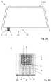
- FIG. 4Aa plan view of another alternative embodiment of an antenna pane according to the invention.
- FIG. 4Ban enlarged representation of the detail Z of FIG. 4A .
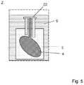
- FIG. 5an enlarged representation of a detail Z of FIG. 4A with an alternative embodiment of an antenna structure according to the invention
- FIG. 6Aa detailed flowchart of an embodiment of the method according to the invention for producing an antenna pane
- FIG. 6Ba detailed flowchart of an embodiment of the method according to the invention for producing an antenna composite pane.
- FIG. 1Adepicts a plan view of an exemplary embodiment of an antenna pane according to the invention 100 using the example of an antenna composite pane 101 .
- FIG. 1Bdepicts an enlarged representation of the detail Z of the antenna composite pane 101 according to the invention of FIG. 1A .
- the antenna composite pane 101comprises, for example, an antenna pane 100 , comprising an inner pane 1 , which is connected to an outer pane 2 via an intermediate layer 3 .
- the antenna composite pane 101is, for example, the windshield of a passenger car.
- the dimensions of the antenna composite pane 101are, for example, 0.9 m ⁇ 1.5 m.
- the inner pane 1is, for example, intended to face the interior in the installed position. In other words, the internal surface IV of the inner pane 1 is accessible from the interior, whereas, in contrast the external surface I of the outer pane 2 faces outward relative to the vehicle interior.
- the inner pane 1 and the outer pane 2are made, for example, of soda lime glass.
- the thickness of the inner pane 1is, for example, 1.6 mm and the thickness of the outer pane 2 is 2.1 mm. it is understood that the inner pane 1 and the outer pane 2 , for example, also can be implemented with the same thickness.
- the intermediate layer 3is a thermoplastic intermediate layer and is made, for example, of polyvinyl butyral (PVB). It has a thickness of 0.76 mm.
- PVBpolyvinyl butyral
- the view shownis a plan view of the external surface I of the outer pane 2 viewed from outside the vehicle.
- FIG. 1Cdepicts a cross-sectional view along the section line A-A′ of FIG. 1B .
- FIG. 1Ddepicts a corresponding cross-sectional view along the section line B-B′ of FIG. 1B .
- the antenna structure 4 and the base plate 5are arranged on the lower pane edge 30 of the antenna pane 100 .
- the antenna structure 4consists in this example of a printed and fired electrically conductive paste, which consists predominantly of silver particles and glass frits.
- the antenna structure 4is arranged on the internal surface IV of the inner pane 1 .
- the antenna structure 4consists in this example of a rectangular base with a length l A of 36 mm and a width b A also of 34 mm.
- the base of the antenna structure 4has, in each case, on two opposite corners a triangular cutout 7 , where, in each case, one of the corners of the square is removed.
- the antenna structure 4additionally has a slot-shaped cutout 6 with a rectangular shape and with a length l S of 9.5 mm and a width b S of 3 mm.
- the slot-shaped cutout 6is arranged with its length along the diagonal of the rectangular base on which the triangular cutouts 7 are situated.
- a dielectric carrier element 9is arranged on the internal surface IV of the inner pane 1 with its external surface V in the region of the orthogonal projection of the antenna structure 4 relative to the inner pane 1 .
- the carrier element 9is, for example, plate-shaped and formed from a solid material.
- the carrier element 9includes a plastic material, here, for example, acrylonitrile butadiene styrene copolymer (ABS).
- Carrier elements 9made of, for example, polybutylene terephthalate (PBT) or polycarbonate (PC) can also be used.
- PBTpolybutylene terephthalate
- PCpolycarbonate
- the carrier element 9is implemented larger in its base than the antenna structure 4 and, in a subregion of the overhang, is glued to the inner pane 1 with an adhesive 21 , for example, a polyurethane (PUR) adhesive.
- PURpoly
- the base plate 5serves as a grounding surface and is arranged on the internal surface VI of the carrier element 9 , i.e., on the side of the carrier element 9 facing away from the antenna structure 4 .
- the base plate 5is, for example, a copper foil with a thickness of 100 ⁇ m, which is glued to the carrier element 9 .
- the base plate 5has a rectangular base with a width b G of 6 cm and a length l G of 13 cm. The base plate 5 protrudes beyond the region of the orthogonal projection of the antenna structure 4 relative to the inner pane 1 .
- the antenna structure 4is connected to the signal line 11 of a foil conductor 10 via an electrical line connection 13 .
- the foil conductor 10is, for example, implemented over its entire length as a coplanar strip conductor.
- the planar signal line 11is surrounded by two planar shields 12 (also referred to as shield conductors) arranged in a plane with the signal line 11 .
- the foil conductor 10thus consists of three inner conductors 15 , namely the signal line 11 and two shields 12 , which can, for example, be surrounded on one side and preferably on both sides by a carrier film that serves as electrical insulation 16 .
- the inner conductors 15i.e., the signal line 11 and the shields 12 are, for example, designed as copper foil with a width of 4 mm and a thickness of 100 ⁇ m.
- the three inner conductors 15 of the foil conductor 10are, in this exemplary embodiment, arranged directly on the carrier element 9 , and attached, for example, on the carrier element 9 by gluing such that no carrier film and no electrical insulation 16 are necessary.
- the signal line 11 and the shields 12 of the foil conductor 10are guided from the external surface V of the carrier element 9 over its side edge 34 onto the internal surface VI of the carrier element 9 .
- the electrical line connection 13 of the signal line 11 to the antenna structure 4is done, for example, by clamping at the time of the gluing of the carrier element 9 on the inner pane 1 .
- the two shields 12are electrically conductively connected on the internal surface VI of the carrier element 9 to the base plate 5 via an electrical line connection 13 .
- the electrical line connection 13is, for example, an electrically conductive adhesive or a solder joint. Alternatively, the electrical line connection 13 can be done by clamping the shields 12 onto the base plate 5 .
- connection element 14for example, a coaxial SMA (sub-miniature A) plug for the connection to reception or transmission electronics and, here, in particular to GNSS reception electronics.
- FIG. 1Edepicts a cross-sectional view along the section line C-C′ of FIG. 1B .
- the orthogonal projection of the antenna structure 4extends over the surface A on the internal surface IV of the inner pane 1 .
- the base plate 5protrudes completely beyond the surface A of the orthogonal projection of the antenna structure 4 .
- the substantially rectangular base of the antenna structure 4is arranged with one side edge parallel to the pane edge 30 . It is understood that the side edge can even have a certain angle relative to the pane edge 30 , for example, 45°.
- the signal line 11is connected to the antenna structure 4 on the side edge of the antenna structure 4 directly adjacent the side edge 30 .
- the slot-shaped cutout 6 and the diagonal with the triangular cutouts 7run, viewed from the connection point of the signal line 11 , from the bottom left to the top right.
- the antenna structure 4 depictedis suitable to receive a right circular polarized GPS signal with an L1 frequency of 1575.42 MHz.
- the antenna structure 4 depictedis also suited to obtain good GLONASS reception.
- the antenna structure 4 and the base plate 5are arranged in a region of the antenna composite pane 101 in which a blockout print 32 in the form a black print is arranged on the internal surface II of the outer pane 2 .
- the blockout print 32is impermeable to visible light and prevents viewing the gluing in of the antenna composite pane 101 in a motor vehicle body or the antenna structure 4 or the base plate 5 .
- the blockout print 32is permeable to electromagnetic radiation in the frequency range of the antenna that is formed by the antenna structure 4 and the base plate 5 . The action of the antenna is not substantially affected by the blockout print 32 , or not at all.
- FIG. 2depicts an antenna pane according to the invention 100 in relation to the emission zone 41 of a satellite 40 for satellite-supported navigation.
- the antenna pane 100comprises an inner pane 1 , an antenna structure 4 , a carrier element 9 , and a base plate 5 .
- the antenna pane 100separates an interior region 50 , for example, the passenger compartment of a vehicle (not depicted here) from an exterior 51 .
- the antenna structure 4is arranged on the internal surface IV of the inner pane 1 .
- the internal surface IVis the surface of the inner pane 1 facing away from the satellite 40 and, hence, the source of the satellite signal.
- the carrier element 9has, consequently, an external surface V, which faces in the direction of the exterior 51 and, hence, in the direction of the signal of the satellite 40 , and an internal surface VI, which is turned away from the exterior 51 .
- the base plate 5is arranged on the internal surface VI of the carrier element 9 and, hence, on the interior side of the antenna structure 4 .
- FIG. 3A to 3Ddepict an alternative exemplary embodiment of an antenna composite pane 101 according to the invention in accordance with FIG. 1A to 1D , wherein only the electrical contacting of the antenna structure 4 is designed differently.
- the signal line 11is arranged in the plane of the base plate 5 and the shield 12 , with the signal line 11 transitioning in one piece into a capacitive coupling region 20 .
- the signal line 11is capacitively coupled to the antenna structure 4 via the dielectric carrier element 9 positioned therebetween.
- the antenna signalis coupled with the capacitive coupling region 20 of the signal line 11 via the dielectric carrier element 9 and directed to the connection element 14 .
- This embodimenthas the particular advantage that neither the signal line 11 nor the shield 12 has to be guided between inner pane 1 and carrier element 9 .
- the complete electrical contactingis done via the plane in which the base plate 5 is arranged.
- This embodimentis particularly advantageous when the carrier element 9 is in a region of a holding mechanism (bracket), for example, a sensor or camera cover.
- a holding mechanismfor example, a sensor or camera cover.
- Such holding mechanismsare usually implemented much larger than the base plate 5 and the antenna structure 4 .
- the signal line 11would have to be guided around the edge of the holding mechanism and would then be very long.
- a holding mechanismwould have to have a through-passage through which the signal line 11 and a possible shield 12 is guided. This is not necessary with the capacitive coupling depicted in FIG. 3A to 3D , since the base plate 5 , the signal line 11 , and the shield 12 are arranged on the internal surface VI of the holding mechanism.
- the design of the holding mechanismcan thus be more simple and more compact.
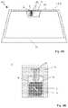
- FIG. 4Adepicts a plan view of another alternative embodiment of an antenna composite pane 101 according to the invention.
- FIG. 4Bdepicts an enlarged representation of the detail Z of FIG. 4A .
- the antenna composite pane 101 of FIG. 4Acorresponds substantially in material and arrangement to the antenna composite pane 101 of FIG. 1A such that, in the following, only the differences between the antenna composite panes 101 are examined in detail.
- the antenna structure 4 and the base plate 5are arranged at the upper side edge 31 of the antenna composite pane 101 .
- the antenna structure 4 and the base plate 5are arranged here in a region of a communication window 33 .
- other sensorssuch as a rain sensor and/or a camera (not shown here) are arranged in the region of the communication window 33 .
- the region of the communication window 33is covered on the vehicle interior side by a plastic housing (not shown here), communication windows 33 , within which the camera and/or the sensors are preferably arranged. Furthermore, the antenna composite pane 101 has, outside the region of the communication window 33 , an electrically conductive coating, that is suitable for reflecting infrared radiation.
- the antenna structure 4 and the base plate 5correspond in their materials and dimensions to the antenna structure 4 and base plate 5 of the exemplary embodiment of FIGS. 1A and 1B .
- the carrier element 9is a holding mechanism (bracket), on which the plastic housing can be attached via a locking mechanism. The carrier element 9 is glued onto the internal surface IV of the inner pane 1 of the antenna composite pane 101 .
- two rectangular cutouts 8are arranged on both sides of the electrical line connection 13 between the antenna structure 4 and the signal line 11 in the base of the antenna structure 4 . These rectangular cutouts 8 improve the decoupling of the antenna signal out of antenna structure 4 .
- the carrier element 9has, in this example, a through-passage 22 , through which the signal line 11 and the shields 12 are guided from the plane of the antenna structure 4 through the carrier element 9 to the plane of the base plate 5 .
- the shield 12is electrically conductively connected to the base plate 5 , and the strip conductor 10 , consisting of signal line 11 and shield 12 , is connected to a connection element 14 .
- the further signal routingis then done, for example, with the wiring harness, with which the other sensors in the plastic housing are contacted.
- FIG. 5depicts an alternative exemplary embodiment of an antenna composite pane 101 according to the invention of FIGS. 4A and 4B , wherein only the base of the antenna structure 4 has a different form than in FIGS. 4A and 4B .
- the baseis an ellipse, with the signal line 11 arranged at an angle of, for example, 45° relative to the major or minor axes.
- the length l A of the base of the antenna structure 4corresponds in this example to the maximum diameter of the ellipse, i.e., the diameter in the direction of the major axis.
- the width b Acorresponds in this example to the minimum diameter of the ellipse.
- FIG. 6Adepicts a flowchart of an exemplary embodiment of the method according to the invention for producing an antenna pane 100 according to the invention.
- FIG. 6Bdepicts a flowchart of an exemplary embodiment of the method according to the invention for producing an antenna composite pane 101 according to the invention.
- the present inventionconsists in providing an improved antenna pane in which an antenna and, in particular, a GNSS antenna can be integrated easily and economically. This result was unexpected and surprising for the person skilled in the art.
Landscapes
- Engineering & Computer Science (AREA)
- Remote Sensing (AREA)
- Details Of Aerials (AREA)
- Support Of Aerials (AREA)
- Joining Of Glass To Other Materials (AREA)
- Waveguide Aerials (AREA)
Abstract
Description
- an inner pane having an internal surface (IV),
- an antenna structure, produced from an electrically conductive paste, which is printed and fired on the internal surface (IV) of the inner pane,
- a dielectric carrier element that is connected to the internal surface (IV) of the inner pane via an external surface (V), preferably by gluing, and has an electrically conductive base plate on an internal surface (VI) of the carrier element,
- wherein
- the base plate is arranged at least in the region of the orthogonal projection of the antenna structure relative to the inner pane.
- an antenna pane according to the invention or an antenna composite pane according to the invention
- receiving or transmitting electronics, which are electrically coupled with the antenna structure and the base plate,
wherein the antenna pane or the antenna composite pane is arranged as glazing in a vehicle body.
- 1 inner pane
- 2 outer pane
- 3 intermediate layer
- 4 antenna structure
- 5 base plate
- 6 slot-shaped cutout
- 7 triangular cutout
- 8 rectangular cutout
- 9 carrier element
- 10 coplanar strip conductor, strip conductor, foil conductor
- 11 signal line
- 12 shield
- 13 electrical line connection
- 14 connection element
- 15 inner conductor
- 16 electrical insulation
- 20 capacitive coupling region
- 21 gluing spot
- 22 through-passage
- 30,31 pane edge
- 32 blockout print
- 33 communication window
- 34 side edge of the
carrier element 9 - 40 satellite
- 41 emission zone of the
satellite 40 - 50 interior
- 51 exterior
- 100 antenna pane
- 101 antenna composite pane
- A area of the orthogonal projection of the
antenna structure 4 - aDleg length of the
triangular cutout 7 - bAwidth of the
antenna structure 4 - bGwidth of the
base plate 5 - bSwidth of the slot-shaped
cutout 6 - d9thickness of the
carrier element 9 - εr,1/2relative permittivity of the
inner pane 1 or theouter pane 2 - εr,3relative permittivity of the
intermediate layer 3 - lAlength of the
antenna structure 4 - lGlength of the
base plate 5 - lSlength of the slot-shaped
cutout 6 - A-A′ section line
- B-B′ section line
- C-C′ section line
- Z detail
- I external surface of the
outer pane 2 - II internal surface of the
outer pane 2 - III external surface of the
inner pane 1 - IV internal surface of the
inner pane 1 - V external surface of the
carrier element 9 - VI internal surface of the
carrier element 9
Claims (34)
Applications Claiming Priority (4)
| Application Number | Priority Date | Filing Date | Title |
|---|---|---|---|
| EP15162764 | 2015-04-08 | ||
| EP15162764 | 2015-04-08 | ||
| EP15162764.3 | 2015-04-08 | ||
| PCT/EP2016/056975WO2016162252A1 (en) | 2015-04-08 | 2016-03-30 | Windscreen antenna |
Publications (2)
| Publication Number | Publication Date |
|---|---|
| US20180037007A1 US20180037007A1 (en) | 2018-02-08 |
| US10665919B2true US10665919B2 (en) | 2020-05-26 |
Family
ID=52814001
Family Applications (1)
| Application Number | Title | Priority Date | Filing Date |
|---|---|---|---|
| US15/555,069Active2036-10-06US10665919B2 (en) | 2015-04-08 | 2016-03-30 | Antenna pane |
Country Status (13)
| Country | Link |
|---|---|
| US (1) | US10665919B2 (en) |
| EP (1) | EP3281248B1 (en) |
| JP (1) | JP6513216B2 (en) |
| KR (1) | KR101973311B1 (en) |
| CN (1) | CN106463812A (en) |
| BR (1) | BR112017020074B1 (en) |
| CA (1) | CA2979601C (en) |
| EA (1) | EA035643B1 (en) |
| ES (1) | ES2847724T3 (en) |
| HU (1) | HUE053722T2 (en) |
| MX (1) | MX384764B (en) |
| PL (1) | PL3281248T3 (en) |
| WO (1) | WO2016162252A1 (en) |
Cited By (1)
| Publication number | Priority date | Publication date | Assignee | Title |
|---|---|---|---|---|
| US20220416399A1 (en)* | 2019-12-05 | 2022-12-29 | Saint-Gobain Glass France | Vehicle pane |
Families Citing this family (18)
| Publication number | Priority date | Publication date | Assignee | Title |
|---|---|---|---|---|
| PL3235339T3 (en) | 2014-12-16 | 2019-08-30 | Saint-Gobain Glass France | Electrically heatable antenna disc and method for producing same |
| HUE054039T2 (en) | 2015-04-08 | 2021-08-30 | Saint Gobain | Vehicle antenna window pane |
| EP3281248B1 (en) | 2015-04-08 | 2020-12-23 | Saint-Gobain Glass France | Antenna disc |
| RU2728837C1 (en)* | 2017-05-24 | 2020-07-31 | Сэн-Гобэн Гласс Франс | Multilayer glass panel and method for production thereof |
| KR102707300B1 (en)* | 2017-08-02 | 2024-09-20 | 에이지씨 가부시키가이샤 | Antenna unit for glass, glass plate with antenna, and method for manufacturing antenna unit for glass |
| BR112020018429A2 (en)* | 2018-03-16 | 2020-12-29 | AGC Inc. | ANTENNA UNIT, WINDOW GLASS FIXED TO THE ANTENNA UNIT AND CORRESPONDENCE BODY |
| WO2019185924A1 (en)* | 2018-03-30 | 2019-10-03 | Agc Glass Europe | Laminated glazing panel having an antenna |
| JP6756868B2 (en)* | 2018-09-14 | 2020-09-16 | 原田工業株式会社 | Antenna device |
| WO2020054870A1 (en)* | 2018-09-14 | 2020-03-19 | 原田工業株式会社 | Antenna device |
| WO2020105670A1 (en)* | 2018-11-22 | 2020-05-28 | Agc株式会社 | Antenna system |
| WO2020157252A1 (en)* | 2019-01-31 | 2020-08-06 | Agc Glass Europe | Insulating glazing unit with antenna unit |
| CN110466323B (en)* | 2019-08-09 | 2021-10-19 | 福耀玻璃工业集团股份有限公司 | Vehicle window glass and vehicle |
| EP4054844A4 (en) | 2019-12-06 | 2023-05-17 | Pittsburgh Glass Works, LLC | MULTI-LAYER GLASS PLANAR ANTENNA |
| CN111987409B (en)* | 2020-08-21 | 2021-11-19 | 福耀玻璃工业集团股份有限公司 | Antenna glass and vehicle |
| WO2022055889A1 (en)* | 2020-09-08 | 2022-03-17 | As America, Inc. | Automatic sanitaryware assembly and systems |
| US11394429B2 (en) | 2020-12-02 | 2022-07-19 | Dupont Electronics, Inc. | Panel having integrated antennas for enhancing range of telecommunication signal transmissions inside buildings |
| GB2605419B (en)* | 2021-03-31 | 2023-12-06 | Jaguar Land Rover Ltd | Vehicle antenna radiator arrangement integrated with vehicle glazing |
| CN118743107A (en)* | 2022-02-17 | 2024-10-01 | Lg电子株式会社 | Transparent antenna |
Citations (61)
| Publication number | Priority date | Publication date | Assignee | Title |
|---|---|---|---|---|
| US3459879A (en) | 1967-05-29 | 1969-08-05 | Hughes Aircraft Co | Flexible multiflat conductor characteristic impedance cable |
| DE3834075A1 (en) | 1987-10-07 | 1989-04-20 | Nippon Sheet Glass Co Ltd | Window antenna |
| EP0608180A1 (en) | 1993-01-21 | 1994-07-27 | Saint Gobain Vitrage International | Method for fabrication of a window antenna and window antenna |
| US5363114A (en) | 1990-01-29 | 1994-11-08 | Shoemaker Kevin O | Planar serpentine antennas |
| EP0720249A2 (en) | 1994-12-27 | 1996-07-03 | Ppg Industries, Inc. | Glass antenna for vehicle window |
| DE19536131C1 (en) | 1995-09-28 | 1997-01-02 | Sekurit Saint Gobain Deutsch | Vehicle diversity antenna plate with multiple connection elements e.g. for FM reception |
| JPH09502073A (en) | 1994-06-15 | 1997-02-25 | サン ゴバン ビトラージュ | Antenna in glass |
| DE19605999A1 (en) | 1996-02-17 | 1997-08-21 | Daimler Benz Ag | Contacting a flat antenna conductor structure |
| DE19735395A1 (en) | 1996-08-16 | 1998-02-19 | Lindenmeier Heinz | Low loss aerial especially for vehicle windscreen |
| US5867238A (en) | 1991-01-11 | 1999-02-02 | Minnesota Mining And Manufacturing Company | Polymer-dispersed liquid crystal device having an ultraviolet-polymerizable matrix and a variable optical transmission and a method for preparing same |
| WO2000022695A1 (en) | 1998-10-12 | 2000-04-20 | Amphenol Socapex | Patch antenna |
| DE19858227C1 (en) | 1998-12-17 | 2000-06-15 | Sekurit Saint Gobain Deutsch | Heat-reflecting coating system for transparent substrate, useful as core of laminated glass, with silver between dielectric titanium dioxide and aluminum nitride has zinc oxide between titanium dioxide and silver |
| US6118410A (en) | 1999-07-29 | 2000-09-12 | General Motors Corporation | Automobile roof antenna shelf |
| US6320276B1 (en) | 1998-07-17 | 2001-11-20 | Saint-Gobain Vitrage | Window with an aerial for motor vehicles |
| US6322881B1 (en) | 1996-12-12 | 2001-11-27 | Saint-Gobain Vitrage | Glazing assembly comprising a substrate provided with a stack of thin layers for solar protection and/or thermal insulation |
| DE10106125A1 (en) | 2001-02-08 | 2002-08-14 | Fuba Automotive Gmbh | Motor vehicle screen with antenna structure has heating/antenna structures covering entire viewing surface and divided into preferably more than two sub-areas and structures |
| DE20210286U1 (en) | 2002-07-03 | 2002-12-12 | FUBA Automotive GmbH & Co. KG, 31162 Bad Salzdetfurth | Adapter for HF connections |
| US20030112190A1 (en) | 2000-04-19 | 2003-06-19 | Baliarda Carles Puente | Advanced multilevel antenna for motor vehicles |
| DE10301352B3 (en) | 2003-01-16 | 2004-07-15 | Saint-Gobain Sekurit Deutschland Gmbh & Co. Kg | Solder terminal element for connecting electrical conductor with conductor structure applied to substrate e.g. automobile windscreen |
| CN1518782A (en) | 2001-06-20 | 2004-08-04 | ����ʥ��ಣ���� | Antenna window with high frequency component |
| US6791496B1 (en) | 2003-03-31 | 2004-09-14 | Harris Corporation | High efficiency slot fed microstrip antenna having an improved stub |
| US20040200812A1 (en) | 2003-04-08 | 2004-10-14 | Grewell David A. | Electronic masking laser imaging system |
| US20040200821A1 (en) | 2003-04-08 | 2004-10-14 | Voeltzel Charles S. | Conductive frequency selective surface utilizing arc and line elements |
| DE10319606A1 (en) | 2003-05-02 | 2004-11-25 | Saint-Gobain Sekurit Deutschland Gmbh & Co. Kg | Antenna disc for vehicles |
| DE202004001446U1 (en) | 2003-11-04 | 2005-03-17 | Saint Gobain Sekurit D Gmbh | Antenna arrangement and window pane with such an antenna arrangement |
| DE102004056866A1 (en) | 2004-11-25 | 2006-01-26 | Leoni Bordnetz-Systeme Gmbh & Co Kg | Extruded flat cable has at least one screened conducting track embedded in insulating material, enclosed by shield, earth conductor that contacts shielding with at least one of its long sides, common casing |
| EP1624527A1 (en) | 2003-04-24 | 2006-02-08 | Asahi Glass Company Ltd. | Antenna device |
| US20060032926A1 (en)* | 2004-08-13 | 2006-02-16 | Fujitsu Limited | Radio frequency identification (RFID) tag and manufacturing method thereof |
| DE202004019286U1 (en) | 2004-12-14 | 2006-04-20 | Saint-Gobain Sekurit Deutschland Gmbh & Co. Kg | Flat, electrically conductive connector element for window panes incorporates a local wear resistant reinforcement which consists of a material capable of self-healing of surface damage |
| JP2006121536A (en) | 2004-10-22 | 2006-05-11 | Asahi Glass Co Ltd | Antenna device and manufacturing method thereof |
| US20060139223A1 (en) | 2004-12-29 | 2006-06-29 | Agc Automotive Americas R&D Inc. | Slot coupling patch antenna |
| US20060202898A1 (en) | 2005-03-11 | 2006-09-14 | Agc Automotive Americas R&D, Inc. | Dual-layer planar antenna |
| DE202006011919U1 (en) | 2006-08-02 | 2006-10-19 | Fuba Automotive Gmbh & Co. Kg | Strip-line antenna e.g. patch antenna, has substrate structure whose base surface leads up to edges of the antenna and designed like frame, i.e. with centrical hollow, and metal layers consisting of metal foils |
| US20070045264A1 (en) | 2004-04-28 | 2007-03-01 | Asahi Glass Company Limited | Glass plate with printed conductive members and method of producing the same |
| US20070216589A1 (en) | 2006-03-16 | 2007-09-20 | Agc Automotive Americas R&D | Multiple-layer patch antenna |
| US20070285323A1 (en)* | 2006-06-12 | 2007-12-13 | Asahi Glass Company, Limited | High frequency wave glass antenna for an automobile |
| EP1898675A2 (en) | 2006-09-11 | 2008-03-12 | Nippon Sheet Glass Company Limited | Rear window glass for vehicles |
| CN101223711A (en) | 2005-07-15 | 2008-07-16 | 罗伯特·博世有限公司 | Wireless device |
| FR2913141A3 (en) | 2007-02-27 | 2008-08-29 | Renault Sas | FLEXIBLE CABLE INTENDED TO BE FIXED ON A GLAZED OR TRANSPARENT SURFACE, SUCH AS A WINDSHIELD OF A MOTOR VEHICLE |
| WO2009015975A1 (en) | 2007-07-30 | 2009-02-05 | Pilkington Automotive Deutschland Gmbh | Improved electrical connector |
| WO2009099427A1 (en) | 2008-02-04 | 2009-08-13 | Agc Automotive Americas R & D, Inc. | Multi-element cavity-coupled antenna |
| DE102008018147A1 (en) | 2008-04-10 | 2009-10-15 | Saint-Gobain Sekurit Deutschland Gmbh & Co. Kg | Transparent disc with a heatable coating and low-resistance conductive structures |
| DE102008029986A1 (en) | 2008-06-24 | 2010-01-07 | Saint-Gobain Sekurit Deutschland Gmbh & Co. Kg | Transparent disk e.g. electrically heatable car glass pane, has electrode connected with pole of current source, so that electrically heatable coating is divided into heating fields with less electric resistance |
| DE202008017611U1 (en) | 2008-12-20 | 2010-04-22 | Saint-Gobain Sekurit Deutschland Gmbh & Co. Kg | Disc-shaped, transparent, electrically heatable composite material |
| WO2010081589A1 (en) | 2009-01-16 | 2010-07-22 | Saint-Gobain Glass France | Transparent, flat antenna, suitable for transmitting and receiving electromagnetic waves, method for the production thereof, and use thereof |
| DE202010011837U1 (en) | 2010-08-26 | 2011-05-12 | Kathrein-Werke Kg | Ceramic patch antenna and ceramic patch antenna mounted on a printed circuit board |
| US20110221652A1 (en) | 2010-03-12 | 2011-09-15 | Agc Automotive Americas R&D, Inc. | Antenna system including a circularly polarized antenna |
| US20110230146A1 (en) | 2008-11-27 | 2011-09-22 | Kyocera Corporation | Communication device |
| US20110233182A1 (en) | 2008-10-27 | 2011-09-29 | Pilkington Automotive Deutschland Gmbh | Heated vehicle window |
| US20110248900A1 (en) | 2009-06-17 | 2011-10-13 | De Rochemont L Pierre | Frequency-selective dipole antennas |
| WO2011144680A1 (en) | 2010-05-19 | 2011-11-24 | Saint Gobain Glass France | Bandwidth-optimized antenna by means of a hybrid design comprising planar and linear antenna elements |
| EP2400591A1 (en) | 2010-06-14 | 2011-12-28 | Saint-Gobain Glass France | Antenna structure with improved signal/noise ratio |
| WO2012052315A1 (en) | 2010-10-19 | 2012-04-26 | Saint-Gobain Glass France | Transparent sheet |
| US20120162047A1 (en) | 2010-12-27 | 2012-06-28 | Canon Components, Inc. | Flexible printed wiring board and wireless communication module |
| WO2012136411A1 (en) | 2011-04-06 | 2012-10-11 | Saint-Gobain Glass France | Flat-conductor connection element for an antenna structure |
| DE102012008033A1 (en) | 2012-03-01 | 2012-11-22 | Daimler Ag | Windscreen device for motor vehicle i.e. passenger car, has windscreen provided with heating device, and antenna arranged in portion for receiving or sending electromagnetic waves, where windscreen is recessed in portion of heating device |
| US20130050983A1 (en) | 2010-07-23 | 2013-02-28 | Saint-Gobain Glass France | Composite glass pane as a head-up display |
| US20140176374A1 (en) | 2012-12-21 | 2014-06-26 | Shan-Gow Lo | Shark Fin Type Car Antenna Assembly |
| WO2016096432A1 (en) | 2014-12-16 | 2016-06-23 | Saint-Gobain Glass France | Electrically heatable windscreen antenna, and method for producing same |
| WO2016162251A1 (en) | 2015-04-08 | 2016-10-13 | Saint-Gobain Glass France | Vehicle window aerial pane |
| WO2016162252A1 (en) | 2015-04-08 | 2016-10-13 | Saint-Gobain Glass France | Windscreen antenna |
Family Cites Families (2)
| Publication number | Priority date | Publication date | Assignee | Title |
|---|---|---|---|---|
| US7126539B2 (en)* | 2004-11-10 | 2006-10-24 | Agc Automotive Americas R&D, Inc. | Non-uniform dielectric beam steering antenna |
| JP2010158035A (en)* | 2010-01-29 | 2010-07-15 | Fujitsu Ltd | Glass antenna, and manufacturing method thereof |
- 2016
- 2016-03-30EPEP16712883.4Apatent/EP3281248B1/enactiveActive
- 2016-03-30HUHUE16712883Apatent/HUE053722T2/enunknown
- 2016-03-30ESES16712883Tpatent/ES2847724T3/enactiveActive
- 2016-03-30WOPCT/EP2016/056975patent/WO2016162252A1/ennot_activeCeased
- 2016-03-30MXMX2017012811Apatent/MX384764B/enunknown
- 2016-03-30USUS15/555,069patent/US10665919B2/enactiveActive
- 2016-03-30BRBR112017020074-0Apatent/BR112017020074B1/ennot_activeIP Right Cessation
- 2016-03-30CNCN201680000920.0Apatent/CN106463812A/enactivePending
- 2016-03-30CACA2979601Apatent/CA2979601C/ennot_activeExpired - Fee Related
- 2016-03-30JPJP2017552950Apatent/JP6513216B2/enactiveActive
- 2016-03-30EAEA201792153Apatent/EA035643B1/ennot_activeIP Right Cessation
- 2016-03-30KRKR1020177027614Apatent/KR101973311B1/enactiveActive
- 2016-03-30PLPL16712883Tpatent/PL3281248T3/enunknown
Patent Citations (94)
| Publication number | Priority date | Publication date | Assignee | Title |
|---|---|---|---|---|
| US3459879A (en) | 1967-05-29 | 1969-08-05 | Hughes Aircraft Co | Flexible multiflat conductor characteristic impedance cable |
| DE3834075A1 (en) | 1987-10-07 | 1989-04-20 | Nippon Sheet Glass Co Ltd | Window antenna |
| US5363114A (en) | 1990-01-29 | 1994-11-08 | Shoemaker Kevin O | Planar serpentine antennas |
| US5867238A (en) | 1991-01-11 | 1999-02-02 | Minnesota Mining And Manufacturing Company | Polymer-dispersed liquid crystal device having an ultraviolet-polymerizable matrix and a variable optical transmission and a method for preparing same |
| US6313796B1 (en) | 1993-01-21 | 2001-11-06 | Saint Gobain Vitrage International | Method of making an antenna pane, and antenna pane |
| JPH06256044A (en) | 1993-01-21 | 1994-09-13 | Saint Gobain Vitrage Internatl | Antenna windowpane and its preparation |
| EP0608180A1 (en) | 1993-01-21 | 1994-07-27 | Saint Gobain Vitrage International | Method for fabrication of a window antenna and window antenna |
| JPH09502073A (en) | 1994-06-15 | 1997-02-25 | サン ゴバン ビトラージュ | Antenna in glass |
| US5760744A (en) | 1994-06-15 | 1998-06-02 | Saint-Gobain Vitrage | Antenna pane with antenna element protected from environmental moisture effects |
| EP0720249A2 (en) | 1994-12-27 | 1996-07-03 | Ppg Industries, Inc. | Glass antenna for vehicle window |
| US5670966A (en) | 1994-12-27 | 1997-09-23 | Ppg Industries, Inc. | Glass antenna for vehicle window |
| DE19536131C1 (en) | 1995-09-28 | 1997-01-02 | Sekurit Saint Gobain Deutsch | Vehicle diversity antenna plate with multiple connection elements e.g. for FM reception |
| DE19605999A1 (en) | 1996-02-17 | 1997-08-21 | Daimler Benz Ag | Contacting a flat antenna conductor structure |
| US6025806A (en) | 1996-02-17 | 2000-02-15 | Daimlerchrysler Ag | Contacting system of a flat antenna conductor structure |
| DE19735395A1 (en) | 1996-08-16 | 1998-02-19 | Lindenmeier Heinz | Low loss aerial especially for vehicle windscreen |
| US6322881B1 (en) | 1996-12-12 | 2001-11-27 | Saint-Gobain Vitrage | Glazing assembly comprising a substrate provided with a stack of thin layers for solar protection and/or thermal insulation |
| EP0847965B1 (en) | 1996-12-12 | 2004-10-20 | Saint-Gobain Glass France | Glazing comprising a substrate furnished with a multiplicity of thin layers providing thermal insulation and/or solar protection |
| US20020045037A1 (en) | 1996-12-12 | 2002-04-18 | Saint-Gobain Vitrage | Glazing assembly comprising a substrate provided with a stack of thin layers for solar protection and / or thermal insulation |
| US6320276B1 (en) | 1998-07-17 | 2001-11-20 | Saint-Gobain Vitrage | Window with an aerial for motor vehicles |
| DE19832228C2 (en) | 1998-07-17 | 2002-05-08 | Saint Gobain Sekurit D Gmbh | Antenna disc for motor vehicles |
| US6285326B1 (en) | 1998-10-12 | 2001-09-04 | Amphenol Socapex | Patch antenna |
| WO2000022695A1 (en) | 1998-10-12 | 2000-04-20 | Amphenol Socapex | Patch antenna |
| DE19858227C1 (en) | 1998-12-17 | 2000-06-15 | Sekurit Saint Gobain Deutsch | Heat-reflecting coating system for transparent substrate, useful as core of laminated glass, with silver between dielectric titanium dioxide and aluminum nitride has zinc oxide between titanium dioxide and silver |
| US6118410A (en) | 1999-07-29 | 2000-09-12 | General Motors Corporation | Automobile roof antenna shelf |
| US6809692B2 (en) | 2000-04-19 | 2004-10-26 | Advanced Automotive Antennas, S.L. | Advanced multilevel antenna for motor vehicles |
| US20030112190A1 (en) | 2000-04-19 | 2003-06-19 | Baliarda Carles Puente | Advanced multilevel antenna for motor vehicles |
| DE10106125A1 (en) | 2001-02-08 | 2002-08-14 | Fuba Automotive Gmbh | Motor vehicle screen with antenna structure has heating/antenna structures covering entire viewing surface and divided into preferably more than two sub-areas and structures |
| US20040178961A1 (en) | 2001-06-20 | 2004-09-16 | Helmut Maeuser | Antenna window with a high-frequency component |
| CN1518782A (en) | 2001-06-20 | 2004-08-04 | ����ʥ��ಣ���� | Antenna window with high frequency component |
| DE20210286U1 (en) | 2002-07-03 | 2002-12-12 | FUBA Automotive GmbH & Co. KG, 31162 Bad Salzdetfurth | Adapter for HF connections |
| DE10301352B3 (en) | 2003-01-16 | 2004-07-15 | Saint-Gobain Sekurit Deutschland Gmbh & Co. Kg | Solder terminal element for connecting electrical conductor with conductor structure applied to substrate e.g. automobile windscreen |
| US6791496B1 (en) | 2003-03-31 | 2004-09-14 | Harris Corporation | High efficiency slot fed microstrip antenna having an improved stub |
| JP2006522565A (en) | 2003-03-31 | 2006-09-28 | ハリス コーポレイション | High efficiency slot fed microstrip antenna with improved stub |
| US20040200812A1 (en) | 2003-04-08 | 2004-10-14 | Grewell David A. | Electronic masking laser imaging system |
| US20040200821A1 (en) | 2003-04-08 | 2004-10-14 | Voeltzel Charles S. | Conductive frequency selective surface utilizing arc and line elements |
| EP1624527A1 (en) | 2003-04-24 | 2006-02-08 | Asahi Glass Company Ltd. | Antenna device |
| US20060109178A1 (en) | 2003-04-24 | 2006-05-25 | Asahi Glass Company Limited | Antenna device |
| CN1778017A (en) | 2003-04-24 | 2006-05-24 | 旭硝子株式会社 | Antenna device |
| US7388548B2 (en) | 2003-05-02 | 2008-06-17 | Saint-Gobain Glass France | Window aerial for motor vehicles |
| DE10319606A1 (en) | 2003-05-02 | 2004-11-25 | Saint-Gobain Sekurit Deutschland Gmbh & Co. Kg | Antenna disc for vehicles |
| US20060273966A1 (en) | 2003-05-02 | 2006-12-07 | Saint-Gobain Glass France | Window aerial for motor vehicles |
| DE10351488A1 (en) | 2003-11-04 | 2005-06-16 | Saint-Gobain Sekurit Deutschland Gmbh & Co. Kg | Antenna arrangement for sending and receiving electromagnetic signals comprises a flat support substrate made from a dielectric material, and strip conductors formed on both surfaces of the substrate |
| DE202004001446U1 (en) | 2003-11-04 | 2005-03-17 | Saint Gobain Sekurit D Gmbh | Antenna arrangement and window pane with such an antenna arrangement |
| US7903042B2 (en) | 2003-11-04 | 2011-03-08 | Saint-Gobain Glass France | Antenna arrangement and window fitted with this antenna arrangement |
| US20070045264A1 (en) | 2004-04-28 | 2007-03-01 | Asahi Glass Company Limited | Glass plate with printed conductive members and method of producing the same |
| CN1946644A (en) | 2004-04-28 | 2007-04-11 | 旭硝子株式会社 | Glass pane with conductive print and method of manufacturing the same |
| US20060032926A1 (en)* | 2004-08-13 | 2006-02-16 | Fujitsu Limited | Radio frequency identification (RFID) tag and manufacturing method thereof |
| JP2006121536A (en) | 2004-10-22 | 2006-05-11 | Asahi Glass Co Ltd | Antenna device and manufacturing method thereof |
| DE102004056866A1 (en) | 2004-11-25 | 2006-01-26 | Leoni Bordnetz-Systeme Gmbh & Co Kg | Extruded flat cable has at least one screened conducting track embedded in insulating material, enclosed by shield, earth conductor that contacts shielding with at least one of its long sides, common casing |
| DE202004019286U1 (en) | 2004-12-14 | 2006-04-20 | Saint-Gobain Sekurit Deutschland Gmbh & Co. Kg | Flat, electrically conductive connector element for window panes incorporates a local wear resistant reinforcement which consists of a material capable of self-healing of surface damage |
| US20060139223A1 (en) | 2004-12-29 | 2006-06-29 | Agc Automotive Americas R&D Inc. | Slot coupling patch antenna |
| US20060202898A1 (en) | 2005-03-11 | 2006-09-14 | Agc Automotive Americas R&D, Inc. | Dual-layer planar antenna |
| US20100141539A1 (en) | 2005-07-15 | 2010-06-10 | Michael Thole | Antenna system |
| CN101223711A (en) | 2005-07-15 | 2008-07-16 | 罗伯特·博世有限公司 | Wireless device |
| US20070216589A1 (en) | 2006-03-16 | 2007-09-20 | Agc Automotive Americas R&D | Multiple-layer patch antenna |
| US7545333B2 (en) | 2006-03-16 | 2009-06-09 | Agc Automotive Americas R&D | Multiple-layer patch antenna |
| JP2007251936A (en) | 2006-03-16 | 2007-09-27 | Agc Automotive Americas R & D Inc | Multiple-layer patch antenna |
| US20070285323A1 (en)* | 2006-06-12 | 2007-12-13 | Asahi Glass Company, Limited | High frequency wave glass antenna for an automobile |
| DE202006011919U1 (en) | 2006-08-02 | 2006-10-19 | Fuba Automotive Gmbh & Co. Kg | Strip-line antenna e.g. patch antenna, has substrate structure whose base surface leads up to edges of the antenna and designed like frame, i.e. with centrical hollow, and metal layers consisting of metal foils |
| EP1898675A2 (en) | 2006-09-11 | 2008-03-12 | Nippon Sheet Glass Company Limited | Rear window glass for vehicles |
| FR2913141A3 (en) | 2007-02-27 | 2008-08-29 | Renault Sas | FLEXIBLE CABLE INTENDED TO BE FIXED ON A GLAZED OR TRANSPARENT SURFACE, SUCH AS A WINDSHIELD OF A MOTOR VEHICLE |
| WO2009015975A1 (en) | 2007-07-30 | 2009-02-05 | Pilkington Automotive Deutschland Gmbh | Improved electrical connector |
| WO2009099427A1 (en) | 2008-02-04 | 2009-08-13 | Agc Automotive Americas R & D, Inc. | Multi-element cavity-coupled antenna |
| US20150232067A1 (en) | 2008-04-10 | 2015-08-20 | Saint-Gobain Glass France | Transparent window with a heatable coating and low-impedance conducting structures |
| DE102008018147A1 (en) | 2008-04-10 | 2009-10-15 | Saint-Gobain Sekurit Deutschland Gmbh & Co. Kg | Transparent disc with a heatable coating and low-resistance conductive structures |
| DE102008029986A1 (en) | 2008-06-24 | 2010-01-07 | Saint-Gobain Sekurit Deutschland Gmbh & Co. Kg | Transparent disk e.g. electrically heatable car glass pane, has electrode connected with pole of current source, so that electrically heatable coating is divided into heating fields with less electric resistance |
| CN102246590A (en) | 2008-10-27 | 2011-11-16 | 皮尔金顿汽车德国有限公司 | Heated vehicle window |
| US20110233182A1 (en) | 2008-10-27 | 2011-09-29 | Pilkington Automotive Deutschland Gmbh | Heated vehicle window |
| US20110230146A1 (en) | 2008-11-27 | 2011-09-22 | Kyocera Corporation | Communication device |
| DE202008017611U1 (en) | 2008-12-20 | 2010-04-22 | Saint-Gobain Sekurit Deutschland Gmbh & Co. Kg | Disc-shaped, transparent, electrically heatable composite material |
| WO2010081589A1 (en) | 2009-01-16 | 2010-07-22 | Saint-Gobain Glass France | Transparent, flat antenna, suitable for transmitting and receiving electromagnetic waves, method for the production thereof, and use thereof |
| US20110279335A1 (en) | 2009-01-16 | 2011-11-17 | Christoph Degen | Transparent, flat antenna, suitable for transmitting and receiving electromagnetic waves, method for the production thereof, and use thereof |
| US20110248900A1 (en) | 2009-06-17 | 2011-10-13 | De Rochemont L Pierre | Frequency-selective dipole antennas |
| US20110221652A1 (en) | 2010-03-12 | 2011-09-15 | Agc Automotive Americas R&D, Inc. | Antenna system including a circularly polarized antenna |
| JP2013522962A (en) | 2010-03-12 | 2013-06-13 | エージーシー オートモーティヴ アメリカズ アールアンドディー,インコーポレイテッド | Antenna system with circularly polarized antenna |
| WO2011144680A1 (en) | 2010-05-19 | 2011-11-24 | Saint Gobain Glass France | Bandwidth-optimized antenna by means of a hybrid design comprising planar and linear antenna elements |
| US20130099981A1 (en) | 2010-05-19 | 2013-04-25 | Saint-Gobain Glass France | Antenna bandwidth-optimized by hybrid structure comprising planar and linear emitters |
| EP2400591A1 (en) | 2010-06-14 | 2011-12-28 | Saint-Gobain Glass France | Antenna structure with improved signal/noise ratio |
| US20130141289A1 (en) | 2010-06-14 | 2013-06-06 | Saint-Gobain Glass France | Antenna assembly and antenna structure with improved signal-to-noise ratio |
| US20130050983A1 (en) | 2010-07-23 | 2013-02-28 | Saint-Gobain Glass France | Composite glass pane as a head-up display |
| CN103228438A (en) | 2010-07-23 | 2013-07-31 | 法国圣戈班玻璃厂 | Composite glass pane as a head-p display |
| DE202010011837U1 (en) | 2010-08-26 | 2011-05-12 | Kathrein-Werke Kg | Ceramic patch antenna and ceramic patch antenna mounted on a printed circuit board |
| WO2012052315A1 (en) | 2010-10-19 | 2012-04-26 | Saint-Gobain Glass France | Transparent sheet |
| US20120162047A1 (en) | 2010-12-27 | 2012-06-28 | Canon Components, Inc. | Flexible printed wiring board and wireless communication module |
| US20140060921A1 (en) | 2011-04-06 | 2014-03-06 | Bernhard Reul | Flat-conductor connection element for an antenna structure |
| WO2012136411A1 (en) | 2011-04-06 | 2012-10-11 | Saint-Gobain Glass France | Flat-conductor connection element for an antenna structure |
| US9171658B2 (en) | 2011-04-06 | 2015-10-27 | Saint-Gobain Glass France | Flat-conductor connection element for an antenna structure |
| DE102012008033A1 (en) | 2012-03-01 | 2012-11-22 | Daimler Ag | Windscreen device for motor vehicle i.e. passenger car, has windscreen provided with heating device, and antenna arranged in portion for receiving or sending electromagnetic waves, where windscreen is recessed in portion of heating device |
| US20140176374A1 (en) | 2012-12-21 | 2014-06-26 | Shan-Gow Lo | Shark Fin Type Car Antenna Assembly |
| WO2016096432A1 (en) | 2014-12-16 | 2016-06-23 | Saint-Gobain Glass France | Electrically heatable windscreen antenna, and method for producing same |
| US20170317399A1 (en) | 2014-12-16 | 2017-11-02 | Saint-Gobain Glass France | Electrically heatable windscreen antenna, and method for producing same |
| WO2016162251A1 (en) | 2015-04-08 | 2016-10-13 | Saint-Gobain Glass France | Vehicle window aerial pane |
| WO2016162252A1 (en) | 2015-04-08 | 2016-10-13 | Saint-Gobain Glass France | Windscreen antenna |
| US20180037006A1 (en) | 2015-04-08 | 2018-02-08 | Saint-Gobain Glass France | Vehicle antenna pane |
Non-Patent Citations (26)
| Title |
|---|
| Canadian Office Action for Canadian Application No. 2,979,601 filed Sep. 13, 2017 on behalf of Saint-Gobain Glass France, dated Jul. 19, 2018. 4 pages. |
| Canadian Office Action for Canadian Application No. 2,979,604 filed on Sep. 13, 2017 on behalf of Saint-Gobain Glass France, dated Jul. 16, 2018 3 pages. |
| Chinese Office Action for Chinese Application No. 201580017710.8 filed on Dec. 2, 2015 on behalf of Saint-Gobain Glass France, dated Nov. 16, 2018. 12 pages. (Chinese Original + English Summary). |
| Chinese Office Action for Chinese Application No. 201680000920.0 filed on Sep. 27, 2016 on behalf of Saint-Gobain Glass France, dated Aug. 31, 2018. 22 pages. (Chinese Original + English Translation). |
| Chinese Office Action for Chinese Application No. 201680000923.4 filed on Sep. 27, 2016 on behalf of Saint-Gobain Glass France, dated Aug. 31, 2018. 22 pages. (Chinese Original + English Translation). |
| International Preliminary Report on Patentability for International Application No. PCT/EP2012/053245 filed on Feb. 27, 2012 on behalf of Saint-Gobain Glass France, dated Oct. 8, 2013. 17 pages. (English Translation + German Original). |
| International Preliminary Report on Patentability for International Application No. PCT/EP2015/078342 filed on Dec. 2, 2015 on behalf of Saint-Gobain Glass France,dated Jun. 20, 2017. 12 pages. (English Translation + German Original). |
| International Preliminary Report on Patentability for International Application No. PCT/EP2016/056975 filed on Mar. 30, 2016 on behalf of Saint-Gobain Glass France, dated Oct. 10, 2017. 14 pages. (English Translation + German Original). |
| International Preliminary Report on Patentability for PCT Patent Application No. PCT/EP2016/056974 filed on Mar. 30, 2016 on behalf of Saint-Gobain Glass France, dated Oct. 10, 2017. 14 pages. (English Translation + German Original). |
| International Search Report for International Application No. PCT/EP2012/053245, filed on Feb. 27, 2012, on behalf of Saint-Gobain Glass France, dated May 11, 2012. 5 pages. (English Translation + German Original). |
| International Search Report for International Application No. PCT/EP2015/078342 filed Dec. 2, 2015 on behalf of Saint-Gobain Glass France, dated Mar. 8, 2016. 4 pages. (English Translation + German Original). |
| International Search Report issued for International Application No. PCT/EP2016/056974, filed Mar. 30, 2016 on behalf of Saint-Gobain Glass France, dated Jun. 3, 2016. 7 pages (German Original + English Translation). |
| International Search Report issued for International Application No. PCT/EP2016/056975, filed Mar. 30, 2016 on behalf of Saint-Gobain Glass France, dated Jun. 13, 2016. 7 pages (German Original + English Translation). |
| J. Hautcoeur, Hautcoeur et al. "Radiofrequency Performance of Transparent Ultra-Wideband Antennas", Process in Electromagnetics Research C, vol. 22, 259-271, 2011 (Year: 2011).* |
| Japanese Office Action for Japanese Application No. 2017-552950 filed on Oct. 6, 2017 on behalf of Saint-Gobain Glass France, dated Nov. 28, 2018. 9 pages. (Japanese Original + English Translation). |
| Japanese Office Action for Japanese Application No. 2017-552951 filed on Oct. 6, 2017 on behalf of Saint-Gobain Glass France, dated Nov. 21, 2018, 6 pages. (Japanese Original + English Translation). |
| Korean Office Action for Korean Application No. 10-2017-7027615 filed on Sep. 28, 2017 on behalf of Saint-Gobain Glass France, dated Jul. 19, 2018. 11 pages. (Korean Original-English Translation). |
| Korean Office Action for Korean Application No. 10-2017-7027615 filed on Sep. 28, 2017 on behalf of Saint-Gobain Glass France, dated Jul. 19, 2018. 11 pages. (Korean Original—English Translation). |
| Non-Final Office Action for U.S. Appl. No. 15/525,935, filed on May 10, 2017, on behalf of Saint-Gobain Glass France, dated Oct. 29, 2018. 24 pages. |
| Notice of Allowance for U.S. Appl. No. 14/110,124, filed on Nov. 21, 2013, on behalf of Saint-Gobain Glass France, dated Sep. 18, 2015. 13 pages. |
| Notice of Allowance for U.S. Appl. No. 15/525,935 filed on May 10, 2017 on behalf of Saint-Gobain Glass France, dated Mar. 21, 2019. 13 pages. |
| PCT Written Opinion for PCT/EP2016/056974 filed Mar. 30, 2016 in the name of Saint-Gobain Glass France, dated Jun. 3, 2016. 12 pages. (English +German). |
| PCT Written Opinion for PCT/EP2016/056975 filed Mar. 30, 2016 in the name of Saint-Gobain Glass France, dated Jun. 13, 2016. 12 pages. (English + German). |
| Restriction Requirement for U.S. Appl. No. 14/110,124, filed on Nov. 21, 2013, on behalf of Saint-Gobain Glass France, dated Jun. 10, 2015. 11 pages. |
| Written Opinion for International Application No. PCT/EP2012/053245, filed on Feb. 27, 2012, on behalf of Saint-Gobain Glass France, dated May 11, 2012. 15 pages. |
| Written Opinion for International Application No. PCT/EP2015/078342 filed Dec. 2, 2015 on behalf of Saint-Gobain Glass France, dated Mar. 8, 2016. 10 pages (English Translation + German Original). |
Cited By (2)
| Publication number | Priority date | Publication date | Assignee | Title |
|---|---|---|---|---|
| US20220416399A1 (en)* | 2019-12-05 | 2022-12-29 | Saint-Gobain Glass France | Vehicle pane |
| US12068524B2 (en)* | 2019-12-05 | 2024-08-20 | Saint-Gobain Glass France | Vehicle pane |
Also Published As
| Publication number | Publication date |
|---|---|
| WO2016162252A1 (en) | 2016-10-13 |
| CA2979601A1 (en) | 2016-10-13 |
| BR112017020074B1 (en) | 2022-09-20 |
| PL3281248T3 (en) | 2021-06-28 |
| KR20170121273A (en) | 2017-11-01 |
| EA201792153A1 (en) | 2018-03-30 |
| KR101973311B1 (en) | 2019-04-26 |
| EP3281248B1 (en) | 2020-12-23 |
| MX384764B (en) | 2025-03-11 |
| EA035643B1 (en) | 2020-07-20 |
| JP2018514149A (en) | 2018-05-31 |
| ES2847724T3 (en) | 2021-08-03 |
| US20180037007A1 (en) | 2018-02-08 |
| EP3281248A1 (en) | 2018-02-14 |
| CA2979601C (en) | 2019-10-29 |
| CN106463812A (en) | 2017-02-22 |
| BR112017020074A2 (en) | 2018-06-05 |
| JP6513216B2 (en) | 2019-05-15 |
| HUE053722T2 (en) | 2021-07-28 |
| MX2017012811A (en) | 2018-01-30 |
Similar Documents
| Publication | Publication Date | Title |
|---|---|---|
| US10665919B2 (en) | Antenna pane | |
| US10737469B2 (en) | Vehicle antenna pane | |
| US11931989B2 (en) | Composite pane with a cutout in the inner pane | |
| KR101571948B1 (en) | Flat-conductor connection element for an antenna structure | |
| JP5650840B2 (en) | Antenna assembly and antenna structure with improved signal-to-noise ratio | |
| CN112020794B (en) | Antenna board | |
| KR102663944B1 (en) | Composite pane containing functional inlay elements | |
| US12083868B2 (en) | Composite pane with functional element and deaeration structure incorporated into a thermoplastic intermediate layer | |
| US11663425B2 (en) | Vehicle window having a transponder | |
| CN114079160A (en) | Glass Mounted Antenna Kits for Motor Vehicles | |
| EA036969B1 (en) | Laminated assembly | |
| CN112714981A (en) | Antenna plate with antenna of planar structure mode | |
| US12151454B2 (en) | Component with electrical functional elements for the production of a laminated sheet | |
| CN111936886A (en) | Antenna device for vehicle |
Legal Events
| Date | Code | Title | Description |
|---|---|---|---|
| FEPP | Fee payment procedure | Free format text:ENTITY STATUS SET TO UNDISCOUNTED (ORIGINAL EVENT CODE: BIG.); ENTITY STATUS OF PATENT OWNER: LARGE ENTITY | |
| AS | Assignment | Owner name:SAINT-GOBAIN GLASS FRANCE, FRANCE Free format text:ASSIGNMENT OF ASSIGNORS INTEREST;ASSIGNORS:DROSTE, STEFAN;STELLING, BERND;FRANCOIS, GUILLAUME;SIGNING DATES FROM 20170912 TO 20170919;REEL/FRAME:043896/0956 | |
| STPP | Information on status: patent application and granting procedure in general | Free format text:DOCKETED NEW CASE - READY FOR EXAMINATION | |
| STPP | Information on status: patent application and granting procedure in general | Free format text:NON FINAL ACTION MAILED | |
| STPP | Information on status: patent application and granting procedure in general | Free format text:RESPONSE TO NON-FINAL OFFICE ACTION ENTERED AND FORWARDED TO EXAMINER | |
| STPP | Information on status: patent application and granting procedure in general | Free format text:NOTICE OF ALLOWANCE MAILED -- APPLICATION RECEIVED IN OFFICE OF PUBLICATIONS | |
| STPP | Information on status: patent application and granting procedure in general | Free format text:PUBLICATIONS -- ISSUE FEE PAYMENT VERIFIED | |
| STCF | Information on status: patent grant | Free format text:PATENTED CASE | |
| MAFP | Maintenance fee payment | Free format text:PAYMENT OF MAINTENANCE FEE, 4TH YEAR, LARGE ENTITY (ORIGINAL EVENT CODE: M1551); ENTITY STATUS OF PATENT OWNER: LARGE ENTITY Year of fee payment:4 | |
| AS | Assignment | Owner name:SAINT-GOBAIN SEKURIT FRANCE, FRANCE Free format text:NUNC PRO TUNC ASSIGNMENT;ASSIGNOR:SAINT-GOBAIN GLASS FRANCE;REEL/FRAME:071969/0743 Effective date:20250505 |