US10663666B2 - Flexible, low profile kink resistant fiber optic splice tension sleeve - Google Patents
Flexible, low profile kink resistant fiber optic splice tension sleeveDownload PDFInfo
- Publication number
- US10663666B2 US10663666B2US14/098,027US201314098027AUS10663666B2US 10663666 B2US10663666 B2US 10663666B2US 201314098027 AUS201314098027 AUS 201314098027AUS 10663666 B2US10663666 B2US 10663666B2
- Authority
- US
- United States
- Prior art keywords
- cable
- tube
- strengthening
- optical fiber
- diameter
- Prior art date
- Legal status (The legal status is an assumption and is not a legal conclusion. Google has not performed a legal analysis and makes no representation as to the accuracy of the status listed.)
- Active, expires
Links
- 239000000835fiberSubstances0.000titleabstractdescription16
- 238000005728strengtheningMethods0.000claimsabstractdescription43
- 239000000463materialSubstances0.000claimsabstractdescription10
- 230000003287optical effectEffects0.000claimsdescription29
- 239000013307optical fiberSubstances0.000claimsdescription26
- 238000005452bendingMethods0.000claimsdescription11
- 230000002787reinforcementEffects0.000claimsdescription10
- 239000004760aramidSubstances0.000claimsdescription3
- 229920003235aromatic polyamidePolymers0.000claimsdescription3
- OKTJSMMVPCPJKN-UHFFFAOYSA-NCarbonChemical compound[C]OKTJSMMVPCPJKN-UHFFFAOYSA-N0.000claimsdescription2
- 229910052799carbonInorganic materials0.000claimsdescription2
- 239000002861polymer materialSubstances0.000claimsdescription2
- 239000003575carbonaceous materialSubstances0.000claims1
- 239000007769metal materialSubstances0.000claims1
- 238000000034methodMethods0.000abstractdescription11
- 229920000642polymerPolymers0.000abstractdescription5
- 230000001681protective effectEffects0.000abstractdescription5
- 230000015572biosynthetic processEffects0.000abstractdescription2
- 239000000126substanceSubstances0.000abstractdescription2
- 239000010410layerSubstances0.000description18
- 239000012790adhesive layerSubstances0.000description10
- 230000008439repair processEffects0.000description10
- 239000000853adhesiveSubstances0.000description3
- 230000001070adhesive effectEffects0.000description3
- 239000011241protective layerSubstances0.000description3
- 239000004593EpoxySubstances0.000description2
- 230000004888barrier functionEffects0.000description2
- 238000005253claddingMethods0.000description2
- 239000002131composite materialSubstances0.000description2
- 239000002654heat shrinkable materialSubstances0.000description2
- 239000002184metalSubstances0.000description2
- 229920001296polysiloxanePolymers0.000description2
- 238000003860storageMethods0.000description2
- 229920002994synthetic fiberPolymers0.000description2
- 239000012209synthetic fiberSubstances0.000description2
- 239000004677NylonSubstances0.000description1
- 230000005856abnormalityEffects0.000description1
- 230000004075alterationEffects0.000description1
- 238000013459approachMethods0.000description1
- -1but not limited toSubstances0.000description1
- 239000011248coating agentSubstances0.000description1
- 238000000576coating methodMethods0.000description1
- 230000000694effectsEffects0.000description1
- 239000012530fluidSubstances0.000description1
- 230000004927fusionEffects0.000description1
- 238000007526fusion splicingMethods0.000description1
- 239000011521glassSubstances0.000description1
- 238000010438heat treatmentMethods0.000description1
- 238000011065in-situ storageMethods0.000description1
- 229920003052natural elastomerPolymers0.000description1
- 229920001194natural rubberPolymers0.000description1
- 229920001778nylonPolymers0.000description1
- 229920005594polymer fiberPolymers0.000description1
- 238000011160researchMethods0.000description1
- 238000012827research and developmentMethods0.000description1
- 239000007787solidSubstances0.000description1
- 239000011343solid materialSubstances0.000description1
- 229920003051synthetic elastomerPolymers0.000description1
- 239000005061synthetic rubberSubstances0.000description1
- 238000012800visualizationMethods0.000description1
- XLYOFNOQVPJJNP-UHFFFAOYSA-NwaterSubstancesOXLYOFNOQVPJJNP-UHFFFAOYSA-N0.000description1
Images


Classifications
- G—PHYSICS
- G02—OPTICS
- G02B—OPTICAL ELEMENTS, SYSTEMS OR APPARATUS
- G02B6/00—Light guides; Structural details of arrangements comprising light guides and other optical elements, e.g. couplings
- G02B6/24—Coupling light guides
- G02B6/255—Splicing of light guides, e.g. by fusion or bonding
- G02B6/2558—Reinforcement of splice joint
- B—PERFORMING OPERATIONS; TRANSPORTING
- B29—WORKING OF PLASTICS; WORKING OF SUBSTANCES IN A PLASTIC STATE IN GENERAL
- B29L—INDEXING SCHEME ASSOCIATED WITH SUBCLASS B29C, RELATING TO PARTICULAR ARTICLES
- B29L2011/00—Optical elements, e.g. lenses, prisms
- B29L2011/0075—Light guides, optical cables
- G—PHYSICS
- G02—OPTICS
- G02B—OPTICAL ELEMENTS, SYSTEMS OR APPARATUS
- G02B6/00—Light guides; Structural details of arrangements comprising light guides and other optical elements, e.g. couplings
- G02B6/44—Mechanical structures for providing tensile strength and external protection for fibres, e.g. optical transmission cables
- G02B6/4401—Optical cables
- G02B6/4429—Means specially adapted for strengthening or protecting the cables
- G02B6/443—Protective covering
- G02B6/4432—Protective covering with fibre reinforcements
- G02B6/4433—Double reinforcement laying in straight line with optical transmission element
Definitions
- This inventionrelates to the field of optical waveguide repair, and more specifically, to a multi-layered apparatus and system for addressing structural differentials introduced when optical cables are spliced.
- Fiber optic cablesare brittle glass or polymer fibers surrounded by a protective layer.
- Fiber optic cablescan include large numbers of signal-carrying fibers, each fiber having a diameter of less than a human hair.
- the fiber-optic “bundle”is protected by an outer cable casing.
- Fiber optic cablesare often buried or submersed, and effectively under high pressure below ground or under water. They may need to be removed and redeployed which can include being rewound on reels. They may also be subjected to pulling forces (“tension”) when the cable is being deployed.
- the thin filament fibers within a cablemay break when the outer housing of a cable is pierced, bent sharply (“kinked”) or crushed. When a breakage in the fibers occurs, each fiber must be spliced back together. Two fiber segments are positioned end-to-end and heat fused to form a single optical fiber.
- the splicing operation and/or makeshift strengthening and protecting measuresresult in geometric abnormalities and protuberances on the outer surface of cable which may cause the repaired cable to catch or snag objects moving across its surface. This may cause damage to the cable when moving or respooling.
- kitsdo not restore the structure of the original layers, focusing instead on providing a portable sleeve that can be used to rapidly cover the splice.
- the shrink-wrapped coveringprovides a simple mechanical interface but does not provide multiple layers of protection.
- kitsoften comprise a single type of fusion splice sleeve for use after a fusion splicing operation. These kits may be a good on-site solution, but alone it has been shown in the art that they are inadequate to assure continued, reliable communications after a repair.
- This inventionis a method and system for addressing structural weaknesses and geometric differentials introduced to a cable when splicing optic fibers.
- the apparatus and method for fiber optic cable repairutilize structurally integrated layers of protective polymers and bonding materials selected for strength and flexibility relative to their thickness. This results in an apparatus having a circumference that is minimally increased over that of the fiber optic cable.
- the method and apparatusinclude one or more polymer strengthening layers which allow the repaired cable sufficient flexibility, but prevent formation of sharp bends which are characteristic of spliced areas.
- the method and apparatusfurther include an outer layer having a geometric configuration which includes sloped terminating ends designed to prevent the reinforced area of the fiber optic cable from being damaged by the force of objects or substances in contact with cable.
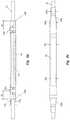
- FIGS. 1 a and 1 billustrate a side view and a cross-sectional view, respectively, of an exemplary layered optical fiber splice protection system.
- FIGS. 2 a through 2 eseparately illustrate the structural properties of each layer of an exemplary layered optical fiber splice protection system.
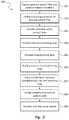
- FIG. 3illustrates an exemplary method for applying a layered optical fiber splice protection system.
- bending modulus Emeans a value of the tendency for a material to bend. Bending modulus is measured as force per unit area.
- the term “plurality”means a quantity of two or more.
- tension modulus Kmeans a value of the maximum pulling force that a material can withstand before breaking. Tension modulus is measured as force per unit area.
- the term “substantially”means all or partially in a manner to effect function, operation or results.
- FIGS. 1 a and 1 billustrate a side view and a cross-sectional view, respectively, of an exemplary layered optical fiber splice protection system.
- the exemplary layered optical fiber splice protection system 100 of FIGS. 1 a and 1 bhas an optical cable 10 , an optical fiber 15 having an outer surface 17 , a splice contact tube 20 with an inner surface 22 and an outer surface 24 , a retaining tube 30 with a retaining tube inner surface 32 , a retaining tube outer surface 34 , and an adhesive moisture barrier layer 35 , strengthening tube 40 with an internal tube surface 42 , an optional longitudinal slit 43 , an external tube surface 44 , a tube adhesive layer 45 , at least one structural reinforcement component 47 and first and second terminating outer rims 49 a and 49 b , an optional curable layer 50 , an outer sleeve 60 with an internal sleeve surface 62 , a tubular center section 64 , a sleeve adhesive layer 65 and first and second sloped terminating ends 69 a and 69 b , and at least two optional securing components 70 a and 70 b each having an inner pressure surface 72 a
- FIGS. 2 a through 2 cillustrate the structural alteration which occurs during each step of the prior art repair process.
- FIG. 2 ashows the optical cable 10 having an external cable diameter CD.
- Optical cable 10is made up of an optical fiber 15 typically surrounded by protective components such as cladding, a coating, a buffer, armored cladding, an aramid synthetic fiber sheath, or a cable jacket. During splicing, all of these protective components are stripped back from optical fiber 15 to permit performance of a splicing connection operation on optical fiber 15 .
- FIG. 2 billustrates the structural properties of an exemplary first layer of an optical fiber splicing system.
- FIG. 2 cillustrates the structural properties of an exemplary second layer of an optical fiber splicing system.
- Retaining tube 30is located over the splice contact tube 20 and structurally conformed to the splice contact tube 20 .
- splice contact tube 20 and retaining tube 30may lack reinforcement or adhesive layers or have a reduced wall thickness. These alternate embodiments reduce the overall profile of the layered optical fiber splice protection system 100 .
- FIG. 2 dillustrates the structural properties of an exemplary third protective layer of an optical fiber splice protection system.
- Strengthening tube 40is located over retaining tube 30 .
- Tube adhesive layer 45( FIG. 1 b ) seals it to optical cable 10 .
- Optional curable layer 50injectable through the longitudinal slit 43 ( FIG. 1 b ) into the volume between internal tube surface 42 and retaining tube 30 , prevents kinking or splitting of the strengthening tube 40 .
- at least two securing components 70 a and 70 bclamp around strengthening tube 40 .
- Strengthening tube 40is has an internal tube diameter TD 1 and an external tube diameter TD 2 .
- strengthening tube 40has an embedded structural reinforcement component 47 ( FIG. 1 b ).
- Strengthening tube 40may also have a longitudinal slit 43 ( FIG. 1 b ) for ease of application.
- the tube adhesive layer 45 on an internal tube surface 42will adhere strengthening tube 40 to optical cable 10 and prevent strengthening tube 40 from splitting or slipping.
- Strengthening tube 40is can be made from materials including, but not limited to polymers, natural or synthetic fiber braid, natural or synthetic rubber tubing, or other solid materials such as flexible metal tube, metal braid, or springs.
- Strengthening tube 40may be a clear polymer to permit proper positioning of strengthening tube 40 and visualization of curable layer 50 .
- the internal tube diameter TD 1 of the strengthening tube 40is greater than the external cable diameter CD of optical cable 10 to enable strengthening tube 40 to be applied around optical cable 10 .
- the strength modulus K s of strengthening tube 40is equal to or greater than the strength modulus K o of optical cable 10 along the axis of the cable.
- two or more of the optional securing components 70 a and 70 bwill be required if the adhesive shear strength of the sleeve adhesive layer 45 is insufficient to carry the tension of optical cable 10 .
- the bending modulus E s of strengthening tube 40 when added to the optical cable 10is within about ten percent above or below the bending modulus E o of optical cable 10 . This prevents excessive bending from being exerted on the optical fiber 15 and prevents optical cable 10 from kinking over first and second terminating outer rims 49 a and 49 b.
- the structural reinforcement component 47is an optional component which increases the tension modulus K s of strengthening tube 40 .
- structural reinforcement component 47can be utilized by strengthening tube 40 .
- the structural reinforcement component 47may be shaped as, but not limited to, at least one band, braid, helix, mesh, sheet or strip.
- the structural reinforcement component 47( FIG. 1 b ) may be fabricated from materials such as, but not limited to, aramid, carbon, metallic and nylon materials.
- Optional curable layer 50may be, but is not limited to, a silicone, epoxy, silicone composite or epoxy composite material. Curable layer 50 is generally a fluid, injectable material which cures in situ to a solid to prevent kinking or splitting the strengthening tube 40 .
- the at least two optional securing components 70 a and 70 bmay be, but are not limited to, a first ring-shaped pressure component 70 a and a second ring-shaped pressure component 70 b . These securing components 70 a and 70 b may be added in pairs placed a first distance D 1 and a second distance D 2 , respectively, from the first and second terminating outer rims 49 a and 49 b . Respective inner pressure surfaces 72 a and 72 b ( FIG. 1 a ) provide pressure on the strengthening tube 40 when applied.
- FIG. 2 eillustrates the structural properties of an exemplary fourth layer of an optical fiber splice protection system.
- the outer sleeve 60is located over strengthening tube 40 and sealed to strengthening tube 40 and optical cable 10 .
- the sleeve adhesive layer 65 on internal sleeve surface 62prevents outer sleeve 60 from slipping from position.
- Outer sleeve 60has a strength modulus K c and a bending modulus E c .
- Outer sleeve 60is fabricated from a heat-shrinkable material, a mechanically expanded polymer material which shrinks in one plane when heated.
- a tube of heat-shrinkable materialshrinks in diameter when heated and activates sleeve adhesive layer 65 upon heating.
- Heat-shrinking outer sleeve 60results in a tubular center section 64 having a first internal sleeve diameter SD 1 approximately equal to external tube diameter TD 2 .
- first and second sloped terminating ends 69 a and 69 bhave maximum internal diameters MD 1 approximately equal to internal diameter SD 1 which gradually slope down to minimum internal diameters MD 2 approximately equal to external cable diameter CD. This provides a smoother, more continuous surface over first and second terminating outer rims 49 a and 49 b of strengthening tube 40 , preventing them from catching and causing damage to strengthening tube 40 .
- Outer sleeve 60 once installedmay have an external sleeve diameter SD 2 in the range of about 10% to about 100% of the external cable diameter CD of optical cable 10 .
- External sleeve diameter SD 2must be minimized to prevent the outer diameter of system 100 from significantly exceeding the outer diameter of optical cable 10 .
- Outer sleeve 60substantially encloses strengthening tube 40 .
- the outer sleeve 60is provided as a single unit layered with the strengthening tube 40 .
- both strengthening tube 40 and outer sleeve 60are applied to optical cable 10 simultaneously.
- Heat-shrinking outer sleeve 60simultaneously applies pressure to seal the tube adhesive layer 45 to optical cable 10 .
- outer sleeve 60may be added directly over the optional curable layer 50 if its tension modulus K c and bending modulus E c are a sufficient match to the tension modulus K o and bending modulus E o of optical cable 10 .
- FIG. 3illustrates an exemplary method for applying a layered optical fiber splice protection system.
- Step 301a user strips back protective components of optical cable 10 to expose the severed optical fiber 15 and positions the splice contact tube 20 , retaining tube 30 , strengthening tube 40 and outer sleeve 60 on optical cable 10 .
- the userperforms a splicing connection operation on optical fiber 15 .
- the userpositions the splice contact tube 20 over the now-spliced optical fiber 15 and shrinks splice contact tube 20 using applied heat.
- Step 304the user positions the retaining tube 30 over splice contact tube 20 and shrinks retaining tube 30 using applied heat.
- the usermoves strengthening tube 40 over retaining tube 30 .
- the userapplies pressure to strengthening tube 40 to seal tube adhesive layer 45 to optical cable 10 .
- the userinjects curable layer 50 through the longitudinal slit 43 of strengthening tube 40 into a volume between internal tube surface 42 and retaining tube 30 .
- the userclamps strengthening tube 40 to optical cable 10 with at least two securing components 70 a and 70 b .
- the userpositions the outer sleeve 60 over strengthening tube 40 and shrinks outer sleeve 60 using applied heat.
Landscapes
- Physics & Mathematics (AREA)
- Engineering & Computer Science (AREA)
- General Physics & Mathematics (AREA)
- Optics & Photonics (AREA)
- Plasma & Fusion (AREA)
- Mechanical Coupling Of Light Guides (AREA)
- Mechanical Engineering (AREA)
Abstract
Description
Claims (2)
Priority Applications (1)
| Application Number | Priority Date | Filing Date | Title |
|---|---|---|---|
| US14/098,027US10663666B2 (en) | 2013-12-05 | 2013-12-05 | Flexible, low profile kink resistant fiber optic splice tension sleeve |
Applications Claiming Priority (1)
| Application Number | Priority Date | Filing Date | Title |
|---|---|---|---|
| US14/098,027US10663666B2 (en) | 2013-12-05 | 2013-12-05 | Flexible, low profile kink resistant fiber optic splice tension sleeve |
Publications (2)
| Publication Number | Publication Date |
|---|---|
| US20150160415A1 US20150160415A1 (en) | 2015-06-11 |
| US10663666B2true US10663666B2 (en) | 2020-05-26 |
Family
ID=53270981
Family Applications (1)
| Application Number | Title | Priority Date | Filing Date |
|---|---|---|---|
| US14/098,027Active2036-10-01US10663666B2 (en) | 2013-12-05 | 2013-12-05 | Flexible, low profile kink resistant fiber optic splice tension sleeve |
Country Status (1)
| Country | Link |
|---|---|
| US (1) | US10663666B2 (en) |
Families Citing this family (8)
| Publication number | Priority date | Publication date | Assignee | Title |
|---|---|---|---|---|
| US10663666B2 (en)* | 2013-12-05 | 2020-05-26 | United States Of America As Represented By The Secretary Of The Navy | Flexible, low profile kink resistant fiber optic splice tension sleeve |
| USD828861S1 (en)* | 2016-04-13 | 2018-09-18 | Global Marine Systems Limited | Fiber optic joint |
| EP3698192A4 (en)* | 2017-10-17 | 2021-09-22 | Corning Research And Development Corporation | HOUSING FOR SPLICE OF OPTICAL FIBERS |
| CN112689782A (en)* | 2018-09-20 | 2021-04-20 | 康普技术有限责任公司 | Laminated joint protector |
| CN110673286B (en)* | 2019-11-01 | 2020-06-23 | 中芳特纤股份有限公司 | Splicing assembly and splicing method for para-aramid fault |
| US11327231B2 (en)* | 2019-12-05 | 2022-05-10 | Commscope Technologies Llc | Flexible splice protector assembly and method for preparing same |
| CN114077012B (en)* | 2020-08-20 | 2024-06-25 | 中国石油天然气股份有限公司 | Splicing structure and method for temperature-measurable movable electric igniter internal cross-connected optical cable |
| WO2025053090A1 (en)* | 2023-09-08 | 2025-03-13 | 住友電工オプティフロンティア株式会社 | Fusion sleeve and method for manufacturing optical connector |
Citations (37)
| Publication number | Priority date | Publication date | Assignee | Title |
|---|---|---|---|---|
| US4545645A (en) | 1982-04-09 | 1985-10-08 | Les Cables De Lyon | Connection joining the ends of two under-water optical fiber cables and a method of manufacturing same |
| US4722588A (en) | 1985-03-01 | 1988-02-02 | Societa' Cavi Pirelli S.P.A. | Joint for optical fiber submarine cables |
| US4812010A (en)* | 1987-02-06 | 1989-03-14 | Sumitomo Electric Industries, Ltd. | Apparatus for arranging a plurality of coated optical fibers and collective fusion splicing method using the apparatus |
| US4824198A (en) | 1983-10-17 | 1989-04-25 | Gte Products Corporation | Housing for a fiber optic splice |
| US5037177A (en)* | 1989-03-21 | 1991-08-06 | Stc Plc | Jointing optical fibre cables |
| US5121458A (en)* | 1991-04-05 | 1992-06-09 | Alcatel Na Cable Systems, Inc. | Preterminated fiber optic cable |
| US5125057A (en)* | 1989-11-20 | 1992-06-23 | At&T Bell Laboratories | Optical fiber splicing device |
| US5315682A (en)* | 1992-07-16 | 1994-05-24 | Alcatel Cable | Splice device for splicing together under-sea optical cables |
| WO1997012268A1 (en) | 1995-09-29 | 1997-04-03 | Psi Telecommunications, Inc. | Fiber optic cable splice closure |
| US5754724A (en)* | 1996-11-08 | 1998-05-19 | Antec Corporation | Fiber optic support apparatus |
| WO1998048308A1 (en) | 1997-04-23 | 1998-10-29 | N.V. Raychem S.A. | Fibre optic splice closure |
| US5884003A (en) | 1995-04-20 | 1999-03-16 | Preformed Line Products Company | Cable splice enclosure with strap member holding stacked splice trays |
| US6099170A (en) | 1999-01-07 | 2000-08-08 | Thomas & Betters International, Inc. | Splice protection sleeve for a plurality of optical fibers and method of installation |
| US6367990B1 (en) | 1999-01-20 | 2002-04-09 | Telefonaktiebolaget Lm Ericsson, (Publ) | Heat-shrinkable tube for protection of optical fiber splices |
| US20020110304A1 (en)* | 2001-02-09 | 2002-08-15 | Werkheiser Arthur H. | Reflection suppression in multiple- reflector collimation system" . |
| US6437299B1 (en)* | 1999-06-29 | 2002-08-20 | Sumitomo Electric Industries, Ltd. | Heating apparatus for splice protector with separate heating conductor patterns |
| US6454471B1 (en)* | 1999-12-01 | 2002-09-24 | Amherst Holding Co. | Optical fiber splice sleeve and method for applying same |
| US6519395B1 (en)* | 2000-05-04 | 2003-02-11 | Northrop Grumman Corporation | Fiber optic array harness |
| US20040048994A1 (en)* | 1998-10-05 | 2004-03-11 | Promerus, Llc | Polymerized cycloolefins using transition metal catalyst and end products thereof |
| US7207732B2 (en)* | 2003-06-04 | 2007-04-24 | Corning Incorporated | Coated optical fiber and curable compositions suitable for coating optical fiber |
| US7364375B1 (en)* | 2006-12-18 | 2008-04-29 | Lockheed Martin Corporation | Method and apparatus for splicing a fiber optic cable |
| US20090052846A1 (en)* | 2006-05-17 | 2009-02-26 | Makoto Miyamori | Optical Fiber Reinforcement Processing Apparatus and Optical Fiber Reinforcement Processing Method |
| US7600928B2 (en)* | 2004-03-24 | 2009-10-13 | Schlumberger Technology Corporation | System and method for performing and protecting hybrid line splices |
| US20110033161A1 (en)* | 2008-01-24 | 2011-02-10 | Masami Ochiai | Resin composition for production of clad layer, resin film for production of clad layer utilizing the resin composition, and optical waveguide and optical module each utilizing the resin composition or the resin film |
| US20110188812A1 (en)* | 2010-02-01 | 2011-08-04 | Hon Fu Jin Precision Industry (Shenzhen) Co., Ltd. | Optical fiber connector |
| US20110280525A1 (en)* | 2010-05-14 | 2011-11-17 | Adc Telecommunications, Inc. | Splice Enclosure Arrangement for Fiber Optic Cables |
| US20120170899A1 (en)* | 2009-03-11 | 2012-07-05 | Nippon Telegraph And Telephone East Corporation | Method for reinforcing a splice part and reinforcing structure |
| US8472768B2 (en)* | 2007-09-19 | 2013-06-25 | Asahi Kasei E-Materials Corporation | Flexible plastic optical fiber cable |
| US20140186312A1 (en)* | 2006-01-12 | 2014-07-03 | Massachusetts Institute Of Technology | Method Comprising Contacting Tissue With a Cross-Linkable Polyester Prepolymer |
| US8787723B2 (en)* | 2009-04-30 | 2014-07-22 | Hitachi Chemical Company, Ltd. | Resin composition for forming optical waveguide, resin film for forming optical waveguide, and optical waveguide |
| US20140355936A1 (en)* | 2012-01-13 | 2014-12-04 | 3M Innovative Properties Company | Connector for telecommunication enclosures |
| US20140373962A1 (en)* | 2013-06-24 | 2014-12-25 | E I Du Pont De Nemours And Company | Multilayer reinforced hose |
| US9052459B2 (en)* | 2012-03-23 | 2015-06-09 | Corning Cable Systems Llc | Cable assembly and method |
| US20150160415A1 (en)* | 2013-12-05 | 2015-06-11 | Jeffrey M. Lloyd | Flexible, Low Profile Kink Resistant Fiber Optic Splice Tension Sleeve |
| US9063286B2 (en)* | 2011-09-26 | 2015-06-23 | Advanced Fiber Products, Limited | Flex tactical cable splice |
| US20150185419A1 (en)* | 2013-03-25 | 2015-07-02 | Fujikura Ltd. | Optical-fiber-spliced portion reinforcing heating device |
| US9343882B2 (en)* | 2013-02-28 | 2016-05-17 | Tyco Electronics (Shanghai) Co. Ltd. | Power cable with ability to provide optical fiber upgrade |
- 2013
- 2013-12-05USUS14/098,027patent/US10663666B2/enactiveActive
Patent Citations (40)
| Publication number | Priority date | Publication date | Assignee | Title |
|---|---|---|---|---|
| US4545645A (en) | 1982-04-09 | 1985-10-08 | Les Cables De Lyon | Connection joining the ends of two under-water optical fiber cables and a method of manufacturing same |
| US4824198A (en) | 1983-10-17 | 1989-04-25 | Gte Products Corporation | Housing for a fiber optic splice |
| US4722588A (en) | 1985-03-01 | 1988-02-02 | Societa' Cavi Pirelli S.P.A. | Joint for optical fiber submarine cables |
| US4812010A (en)* | 1987-02-06 | 1989-03-14 | Sumitomo Electric Industries, Ltd. | Apparatus for arranging a plurality of coated optical fibers and collective fusion splicing method using the apparatus |
| US5037177A (en)* | 1989-03-21 | 1991-08-06 | Stc Plc | Jointing optical fibre cables |
| US5125057A (en)* | 1989-11-20 | 1992-06-23 | At&T Bell Laboratories | Optical fiber splicing device |
| US5121458A (en)* | 1991-04-05 | 1992-06-09 | Alcatel Na Cable Systems, Inc. | Preterminated fiber optic cable |
| US5315682A (en)* | 1992-07-16 | 1994-05-24 | Alcatel Cable | Splice device for splicing together under-sea optical cables |
| US5884003A (en) | 1995-04-20 | 1999-03-16 | Preformed Line Products Company | Cable splice enclosure with strap member holding stacked splice trays |
| WO1997012268A1 (en) | 1995-09-29 | 1997-04-03 | Psi Telecommunications, Inc. | Fiber optic cable splice closure |
| US5754724A (en)* | 1996-11-08 | 1998-05-19 | Antec Corporation | Fiber optic support apparatus |
| WO1998048308A1 (en) | 1997-04-23 | 1998-10-29 | N.V. Raychem S.A. | Fibre optic splice closure |
| US20040048994A1 (en)* | 1998-10-05 | 2004-03-11 | Promerus, Llc | Polymerized cycloolefins using transition metal catalyst and end products thereof |
| US6099170A (en) | 1999-01-07 | 2000-08-08 | Thomas & Betters International, Inc. | Splice protection sleeve for a plurality of optical fibers and method of installation |
| US6367990B1 (en) | 1999-01-20 | 2002-04-09 | Telefonaktiebolaget Lm Ericsson, (Publ) | Heat-shrinkable tube for protection of optical fiber splices |
| US6437299B1 (en)* | 1999-06-29 | 2002-08-20 | Sumitomo Electric Industries, Ltd. | Heating apparatus for splice protector with separate heating conductor patterns |
| US6454471B1 (en)* | 1999-12-01 | 2002-09-24 | Amherst Holding Co. | Optical fiber splice sleeve and method for applying same |
| US6519395B1 (en)* | 2000-05-04 | 2003-02-11 | Northrop Grumman Corporation | Fiber optic array harness |
| US20020110304A1 (en)* | 2001-02-09 | 2002-08-15 | Werkheiser Arthur H. | Reflection suppression in multiple- reflector collimation system" . |
| US7207732B2 (en)* | 2003-06-04 | 2007-04-24 | Corning Incorporated | Coated optical fiber and curable compositions suitable for coating optical fiber |
| US7600928B2 (en)* | 2004-03-24 | 2009-10-13 | Schlumberger Technology Corporation | System and method for performing and protecting hybrid line splices |
| US20140186312A1 (en)* | 2006-01-12 | 2014-07-03 | Massachusetts Institute Of Technology | Method Comprising Contacting Tissue With a Cross-Linkable Polyester Prepolymer |
| US20090052846A1 (en)* | 2006-05-17 | 2009-02-26 | Makoto Miyamori | Optical Fiber Reinforcement Processing Apparatus and Optical Fiber Reinforcement Processing Method |
| US7699540B2 (en)* | 2006-05-17 | 2010-04-20 | Sumitomo Electric Industries, Ltd. | Optical fiber reinforcement processing apparatus and optical fiber reinforcement processing method |
| US7364375B1 (en)* | 2006-12-18 | 2008-04-29 | Lockheed Martin Corporation | Method and apparatus for splicing a fiber optic cable |
| US8472768B2 (en)* | 2007-09-19 | 2013-06-25 | Asahi Kasei E-Materials Corporation | Flexible plastic optical fiber cable |
| US20110033161A1 (en)* | 2008-01-24 | 2011-02-10 | Masami Ochiai | Resin composition for production of clad layer, resin film for production of clad layer utilizing the resin composition, and optical waveguide and optical module each utilizing the resin composition or the resin film |
| US9004781B2 (en)* | 2009-03-11 | 2015-04-14 | Sumitomo Electric Industries, Ltd. | Method for reinforcing a splice part and reinforcing structure |
| US20120170899A1 (en)* | 2009-03-11 | 2012-07-05 | Nippon Telegraph And Telephone East Corporation | Method for reinforcing a splice part and reinforcing structure |
| US8787723B2 (en)* | 2009-04-30 | 2014-07-22 | Hitachi Chemical Company, Ltd. | Resin composition for forming optical waveguide, resin film for forming optical waveguide, and optical waveguide |
| US20110188812A1 (en)* | 2010-02-01 | 2011-08-04 | Hon Fu Jin Precision Industry (Shenzhen) Co., Ltd. | Optical fiber connector |
| US20110280525A1 (en)* | 2010-05-14 | 2011-11-17 | Adc Telecommunications, Inc. | Splice Enclosure Arrangement for Fiber Optic Cables |
| US8915659B2 (en)* | 2010-05-14 | 2014-12-23 | Adc Telecommunications, Inc. | Splice enclosure arrangement for fiber optic cables |
| US9063286B2 (en)* | 2011-09-26 | 2015-06-23 | Advanced Fiber Products, Limited | Flex tactical cable splice |
| US20140355936A1 (en)* | 2012-01-13 | 2014-12-04 | 3M Innovative Properties Company | Connector for telecommunication enclosures |
| US9052459B2 (en)* | 2012-03-23 | 2015-06-09 | Corning Cable Systems Llc | Cable assembly and method |
| US9343882B2 (en)* | 2013-02-28 | 2016-05-17 | Tyco Electronics (Shanghai) Co. Ltd. | Power cable with ability to provide optical fiber upgrade |
| US20150185419A1 (en)* | 2013-03-25 | 2015-07-02 | Fujikura Ltd. | Optical-fiber-spliced portion reinforcing heating device |
| US20140373962A1 (en)* | 2013-06-24 | 2014-12-25 | E I Du Pont De Nemours And Company | Multilayer reinforced hose |
| US20150160415A1 (en)* | 2013-12-05 | 2015-06-11 | Jeffrey M. Lloyd | Flexible, Low Profile Kink Resistant Fiber Optic Splice Tension Sleeve |
Non-Patent Citations (3)
| Title |
|---|
| "Fiber Optic Construction Tool Kit FS-6500N", Oct. 7, 2013, http://www.fiberstore.com/fiber-optic-construction-tool-kit-fs-6500n-p-13698.html. |
| "Harsh Environment Fiber Cable Repair Kit", Oct. 2012, http://www.timbercon.com/assets/Uploads/fiber-optic-cable-repair-kits/Harsh-Env.-Fiber-Cable-repair-kit.pdf. |
| "Installation Guide", Oct. 7, 2013, http://www.timbercon.com/assets/Uploads/fiber-optic-cable-repair-kits/4-Fiber-Military-Cable-Installation-Guide.pdf. |
Also Published As
| Publication number | Publication date |
|---|---|
| US20150160415A1 (en) | 2015-06-11 |
Similar Documents
| Publication | Publication Date | Title |
|---|---|---|
| US10663666B2 (en) | Flexible, low profile kink resistant fiber optic splice tension sleeve | |
| US7218821B2 (en) | Optical fiber cables | |
| KR100295357B1 (en) | Fiber optic cable | |
| EP2184631B1 (en) | Self healing optical fiber cable assembly and method for making the same | |
| JP6674893B2 (en) | Optical fiber cable with outer material | |
| US7025509B2 (en) | Cable sleeve and method of installation | |
| US7590321B2 (en) | Mid-span breakout with helical fiber routing | |
| US7424189B2 (en) | Mid-span breakout with potted closure | |
| US11287596B2 (en) | Methods, kits, and systems incorporating a self-amalgamating tape for clamping fiber optic cable | |
| US9343882B2 (en) | Power cable with ability to provide optical fiber upgrade | |
| JPH05142428A (en) | Optical fiber cable having fiber branch without splice and manufacture thereof | |
| CA2255175A1 (en) | Fiber optic cable | |
| AU2014216530A1 (en) | Fiber optic cable assembly | |
| US20210116661A1 (en) | Flexible splice protector | |
| US20190250346A1 (en) | Predefined cylindrical enclosure for optical waveguide cable | |
| US6996314B2 (en) | Air-blown fiber optic cable | |
| US12204160B2 (en) | Pulling terminal structure, pulling-end-equipped optical cable, and method for manufacturing pulling-end-equipped optical cable | |
| US4427262A (en) | Armor wire splices | |
| CN114641717A (en) | Optical cable and method for manufacturing optical cable | |
| US7149392B2 (en) | Round multi-fiber cable assembly and a method of forming same | |
| AU2011100839A4 (en) | A flexible stranded optical fiber cable | |
| JP2017068220A (en) | Connection structure and connection method of metal tube covered optical fiber cable | |
| JP6230553B2 (en) | Terminal structure of loose tube type optical fiber cable and method of manufacturing the terminal structure | |
| EP2120076B9 (en) | Method for the installation of an optical fibre telecommunication cable | |
| US20240255716A1 (en) | Armored, insulated, fiber optic cables |
Legal Events
| Date | Code | Title | Description |
|---|---|---|---|
| AS | Assignment | Owner name:UNITED STATES OF AMERICA AS REPRESENTED BY THE SECRETARY OF THE NAVY, VIRGINIA Free format text:GOVERNMENT INTEREST AGREEMENT;ASSIGNORS:LLOYD, JEFFREY M.;WIEDEMEIER, BRANDON J.;REEL/FRAME:031767/0358 Effective date:20131202 Owner name:UNITED STATES OF AMERICA AS REPRESENTED BY THE SEC Free format text:GOVERNMENT INTEREST AGREEMENT;ASSIGNORS:LLOYD, JEFFREY M.;WIEDEMEIER, BRANDON J.;REEL/FRAME:031767/0358 Effective date:20131202 | |
| STCV | Information on status: appeal procedure | Free format text:ON APPEAL -- AWAITING DECISION BY THE BOARD OF APPEALS | |
| STCV | Information on status: appeal procedure | Free format text:BOARD OF APPEALS DECISION RENDERED | |
| STPP | Information on status: patent application and granting procedure in general | Free format text:PUBLICATIONS -- ISSUE FEE PAYMENT VERIFIED | |
| STCF | Information on status: patent grant | Free format text:PATENTED CASE | |
| MAFP | Maintenance fee payment | Free format text:PAYMENT OF MAINTENANCE FEE, 4TH YEAR, LARGE ENTITY (ORIGINAL EVENT CODE: M1551); ENTITY STATUS OF PATENT OWNER: LARGE ENTITY Year of fee payment:4 |