US10662045B2 - Control augmentation apparatus and method for automated guided vehicles - Google Patents
Control augmentation apparatus and method for automated guided vehiclesDownload PDFInfo
- Publication number
- US10662045B2 US10662045B2US15/429,222US201715429222AUS10662045B2US 10662045 B2US10662045 B2US 10662045B2US 201715429222 AUS201715429222 AUS 201715429222AUS 10662045 B2US10662045 B2US 10662045B2
- Authority
- US
- United States
- Prior art keywords
- control
- agv
- data
- sensor
- sensor data
- Prior art date
- Legal status (The legal status is an assumption and is not a legal conclusion. Google has not performed a legal analysis and makes no representation as to the accuracy of the status listed.)
- Active, expires
Links
Images


Classifications
- B—PERFORMING OPERATIONS; TRANSPORTING
- B66—HOISTING; LIFTING; HAULING
- B66F—HOISTING, LIFTING, HAULING OR PUSHING, NOT OTHERWISE PROVIDED FOR, e.g. DEVICES WHICH APPLY A LIFTING OR PUSHING FORCE DIRECTLY TO THE SURFACE OF A LOAD
- B66F9/00—Devices for lifting or lowering bulky or heavy goods for loading or unloading purposes
- B66F9/06—Devices for lifting or lowering bulky or heavy goods for loading or unloading purposes movable, with their loads, on wheels or the like, e.g. fork-lift trucks
- B66F9/063—Automatically guided
- B—PERFORMING OPERATIONS; TRANSPORTING
- B66—HOISTING; LIFTING; HAULING
- B66F—HOISTING, LIFTING, HAULING OR PUSHING, NOT OTHERWISE PROVIDED FOR, e.g. DEVICES WHICH APPLY A LIFTING OR PUSHING FORCE DIRECTLY TO THE SURFACE OF A LOAD
- B66F9/00—Devices for lifting or lowering bulky or heavy goods for loading or unloading purposes
- B66F9/06—Devices for lifting or lowering bulky or heavy goods for loading or unloading purposes movable, with their loads, on wheels or the like, e.g. fork-lift trucks
- B66F9/075—Constructional features or details
- B66F9/0755—Position control; Position detectors
- G—PHYSICS
- G05—CONTROLLING; REGULATING
- G05D—SYSTEMS FOR CONTROLLING OR REGULATING NON-ELECTRIC VARIABLES
- G05D1/00—Control of position, course, altitude or attitude of land, water, air or space vehicles, e.g. using automatic pilots
- G05D1/02—Control of position or course in two dimensions
- G05D1/021—Control of position or course in two dimensions specially adapted to land vehicles
- G05D1/0231—Control of position or course in two dimensions specially adapted to land vehicles using optical position detecting means
- G05D1/0238—Control of position or course in two dimensions specially adapted to land vehicles using optical position detecting means using obstacle or wall sensors
- G05D2201/0216—
Definitions
- the specificationrelates generally to automated guided vehicles, and specifically to a control augmentation apparatus and method for automated guided vehicles.
- Automated guided vehiclesare employed in a variety of settings, including industrial settings such as warehouse facilities (e.g. for retrieving and moving inventory, or for in-process assembly).
- the deployment of some AGVsrequires the accompanying deployment of physical infrastructure in the facility, such as magnetic or coloured tape, reflectors, RFID tags, and the like.
- Such infrastructurecan be detected by the AGVs, which are in turn configured to execute instructions based on which infrastructure elements they detect.
- Systems such as those described abovecan be time-consuming and costly to deploy, and are also not suitable in some environments.
- the guiding infrastructureis subject to wear and tear and accidental damage, which can result in interruptions to AGV operations while the infrastructure is repaired or replaced.
- the above-mentioned AGVsare typically capable of executing only a limited set of instructions, requiring the system operators to translate complex spatial and process requirements into such limited instruction sets.
- FIG. 1depicts an unaugmented automated guided vehicle, according to a non-limiting embodiment
- FIG. 2depicts an augmented automated guided vehicle, according to a non-limiting embodiment
- FIG. 3depicts certain internal components of the vehicle of FIG. 2 , according to a non-limiting embodiment
- FIG. 4depicts a method of control augmentation in the vehicle of FIG. 2 , according to a non-limiting embodiment
- FIG. 5depicts an example overhead view of the operation of the AGV of FIG. 2 in a facility
- FIG. 6depicts an example of an AGV consisting of a human-operated vehicle equipped with a control module and navigation sensors according to a non-limiting embodiment.
- FIG. 1depicts an automated guided vehicle (AGV) 100 according to certain non-limiting embodiments.
- AGV 100in the configuration shown in FIG. 1 , is referred to as an unaugmented or legacy AGV.
- AGV 100is a tow vehicle in the example of FIG. 1 , configured to attach to a cart (not shown) and tow the cart about a facility in which AGV is deployed.
- AGV 100can have any of a wide variety of other form factors, including other land-based configurations (e.g. with payload-bearing surfaces for carrying payloads directly on the AGV), marine configurations and aerial configurations.
- AGV 100includes a chassis 104 supporting various other components, including a locomotion assembly enabling AGV 100 to move about the facility (e.g. a building such as a warehouse, a collection of buildings, an outdoor space, and the like).
- the locomotion assemblyin the example of FIG. 1 , includes a pair of wheels 108 powered by a drive mechanism 112 .
- different numbers of wheels in different positions on chassis 104can be implemented.
- other locomotion assembliescan be employed that include propellers or rotors instead of, or in addition to, wheels 108 .
- Drive mechanism 112in the example of FIG. 1 , includes an electric motor connected to each wheel 108 —that is, wheels 108 are differentially driven, permitting AGV 100 to steer by rotating each wheel 108 at a different rate.
- AGV 100also includes at least one tow pin 116 in the present example, which can be raised and lowered (together or independently, if multiple tow pins 116 are provided) from an upper surface of chassis 104 to attach and release AGV 100 to and from the above-mentioned carts.
- Tow pin 116may be omitted in other embodiments (e.g. those in which AGV 100 bears a payload directly on its upper surface), or replaced with other structures (hooks, anchors, forks for AGVs configured to operate as forklifts, and the like) for securing loads or tools.
- AGV 100includes a control module 120 .
- Control module 120in general, interfaces with drive mechanism 112 to control the direction and speed of movement of AGV 100 .
- Control module 120can also control the deployment and retraction of tow pin 116 .
- Control of the movement of AGV 100can be exerted by a processor executing a navigation application within control module 120 .
- control module 120receives data from a navigation sensor 124 mounted adjacent to drive mechanism 112 .
- Navigation sensor 124is illustrated as a magnetic field sensor that detects the position of a magnetic field, such as that emitted by a strip of magnetic tape 128 placed on the floor of the facility.
- navigation sensor 124typically reports a position of magnetic tape 128 relative to the center of the sensor or to one side of the sensor.
- Control module 120receives the reported position of tape 128 , and controls drive mechanism 112 based on the difference between the reported position and a target position stored at control module 120 .
- control module 120is configured to adjust the control of drive mechanism 112 to correct deviations in the position of tape 128 from the center of sensor 124 .
- control module 120is configured to guide AGV 100 along the length of tape 128 .
- AGV 100can also include a variety of other navigation sensors for detecting associated infrastructure elements and reporting those elements to control module 120 .
- AGV 100can be equipped with one or more cameras to detect colored tape (instead of or in addition to magnetic tape 128 ) or other objects (e.g. reflective markers) in the facility.
- AGV 100can be equipped with a radio-frequency identification (RFID) reader to detect RFID tags placed throughout the facility. The detection of a given RFID tag can be interpreted by control module 120 as an instruction to perform an action (e.g. stop, wait for a preconfigured time period, and the like).
- RFIDradio-frequency identification
- AGV 100can also include a range-finding sensor 132 , such as a LIDAR sensor.
- Sensor 132can be implemented as a safety sensor that interrupts the movement of AGV 100 when an obstacle is detected within a threshold distance (e.g. one meter) of AGV 100 .
- sensor 132can be connected directly to drive mechanism 112 rather than to control module 120 .
- sensor 132can be connected to control module, which can in turn issue any required interrupt signals when obstacles are detected by sensor 132 .
- sensor 132can also be employed for navigational purposes extending beyond interrupting operation of AGV 100 in response to obstacle detections.
- AGV 100also includes a human-machine interface (HMI) for presenting status information and receiving instructions from an operator.
- HMIhuman-machine interface
- the HMIincludes, in the example of FIG. 1 , a display 136 and at least one input device 140 such as a button, switch or the like.
- the components of the HMIare connected to the processor of control module 120 . In other examples, some or all of the HMI can be omitted.
- AGV 200is illustrated according to certain non-limiting embodiments.
- AGV 200includes the components mentioned initially herein as being omitted from AGV 100 .
- AGV 200is also referred to as an augmented AGV.
- AGV 200includes the components of AGV 100 as described above, and also includes an augmentation module 204 coupled to chassis 104 .
- augmentation module 204is coupled to chassis 104 at the opposite end of chassis 104 from control module 120 .
- both control module 120 and augmentation module 204can be coupled to chassis 104 at any suitable location.
- augmentation module 204can, in some embodiments, be installed in a space within chassis 104 rather than being coupled to an outer surface of chassis 104 .
- augmentation module 204is configured to intermediate, at least under certain conditions, between the sensors (such as navigation sensor 124 ) of AGV 200 and control module 120 .
- augmentation module 204can generate data defining desired movement or other operations of AGV 200 , and convert such control data into simulated sensor data and send the simulated sensor data to control module 120 .
- Control module 120controls drive mechanism 112 based on the simulated sensor data (as mentioned earlier) and is thus enabled to guide AGV 200 even in the absence of infrastructure such as tape 128 .
- AGV 200can also include additional components, such as a differential drive rotation sensor 208 coupled to drive mechanism 112 and one or more automation interfaces, such as a power data interface 210 for providing augmentation module 204 with data defining a remaining level of power (e.g. battery charge) for AGV 200 . In other embodiments, however, such additional components can be omitted.
- AGV 200can include additional sensors, either mounted on chassis 104 or on augmentation module 204 .
- augmentation module 204can include auxiliary navigation sensors (e.g. additional LIDAR sensors, cameras, global positioning system (GPS) sensors, and the like).
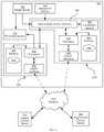
- AGV 200Before a detailed discussion of the operation of AGV 200 , certain internal components of AGV 200 will be described with reference to FIG. 3 . As will now be apparent, various components of AGV 200 , such as display 136 and sensor 208 , are not shown in FIG. 3 for simplicity of illustration. It will also be apparent that other components of AGV not directly related to the present invention are not shown herein, including a power source (e.g. batteries, solar panels, fuel tank or the like) for the above-mentioned modules and drive mechanism, as well as safety systems.
- a power sourcee.g. batteries, solar panels, fuel tank or the like
- control module 120includes a central processing unit (CPU) 300 , also referred to as a processor 300 , interconnected with a non-transitory computer-readable medium such as a memory 304 .
- processor 300 and memory 304are generally comprised of one or more integrated circuits (ICs), and can have a variety of structures, as will now occur to those skilled in the art (for example, more than one CPU can be provided).
- Memory 304can be any suitable combination of volatile (e.g. Random Access Memory (“RAM”)) and non-volatile (e.g. read only memory (“ROM”), Electrically Erasable Programmable Read Only Memory (“EEPROM”), flash memory, magnetic computer storage device, or optical disc) memory.
- RAMRandom Access Memory
- ROMread only memory
- EEPROMElectrically Erasable Programmable Read Only Memory
- flash memorymagnetic computer storage device, or optical disc
- Control module 120also includes a communications interface connected with processor 300 .
- Communications interfaceincludes any necessary hardware (executing any suitable programming instructions) for connecting control module to a network 310 .
- the nature of network 310is not particularly limited—network 310 can be implemented as any suitable one of, or combination of, wired and wireless networks.
- network 310is a local wireless network, and thus communications interface includes one or more radio assemblies for sending and receiving data via network 310 .
- control module 120communicates with a legacy control server 312 via communications interface 308 and network 310 .
- Memory 304stores a plurality of computer readable instructions executable by processor 300 , including a locomotion application 316 .
- Application 316contains a set of instructions for use in controlling the operation of AGV 200 .
- Each instructionwhen executed by processor 304 , generates output data for controlling drive mechanism 112 .
- Some instructionsaccept sensor data as inputs—for example, an instruction for following tape 128 , as will now be apparent to those skilled in the art, may take the position of tape 128 as reported by sensor 124 and generate output data for drive mechanism 112 based on the deviation of the reported position of tape 128 and a target position of tape 128 .
- Another example instruction for stopping AGV 200may accept as input an identifier from an RFID tag, and generate output data to slow and stop operation of drive mechanism 112 .
- Other instructionswill also occur to those skilled in the art (e.g. an instruction defining which portion of a branch in tape 128 to follow).
- the above-mentioned instructionscan be preconfigured in memory 304 .
- the instructionscan also be deployed to memory 304 , and updated in memory 304 , from legacy control server 312 via network 310 .
- Augmentation module 204includes a CPU 320 , also referred to as a processor 320 , interconnected with a non-transitory computer-readable medium such as a memory 324 .
- Processor 320 and memory 324are generally comprised of one or more integrated circuits (ICs), and can have a variety of structures, as will now occur to those skilled in the art (for example, more than one CPU can be provided).
- Memory 324can be any suitable combination of volatile (e.g. Random Access Memory (“RAM”)) and non-volatile (e.g. read only memory (“ROM”), Electrically Erasable Programmable Read Only Memory (“EEPROM”), flash memory, magnetic computer storage device, or optical disc) memory.
- RAMRandom Access Memory
- ROMread only memory
- EEPROMElectrically Erasable Programmable Read Only Memory
- flash memorymagnetic computer storage device, or optical disc
- Augmentation module 204also includes a communications interface 328 interconnected with processor 320 . Via communications interface 328 and network 310 , augmentation module 204 can send and receive data to and from an augmented control server 330 , as will be discussed below in greater detail. As noted above in connection with interface 308 , the nature of interface 328 can vary based on the nature of network 310 . In the present example, in which network 310 is a local wireless network deployed within the facility, interface 328 includes one or more radio assemblies, and any necessary supporting hardware.
- augmentation module 204includes an inter-module communications interface 332 .
- interface 332interconnects processor 320 , processor 300 , range sensor 132 and navigation sensor 124 .
- Sensor 132may also, as shown in FIG. 3 , be connected directly to drive mechanism 112 .
- sensor 132can be implemented as a safety sensor.
- sensor 132in addition to providing range-finding data to interface 332 , sensor 132 can send commands (e.g. interrupt commands) directly to drive mechanism 112 to interrupt the operation of AGV 200 when sensor 132 detects an obstacle within a preconfigured threshold distance of AGV 200 .
- Sensor 334can be an additional range-finding sensor (e.g. a LIDAR sensor), an image sensor such as a camera, or the like.
- a LIDAR sensore.g. a LIDAR sensor
- sensor 334can be employed instead of, or in addition to, sensor 132 for such processes.
- Interface 332can have a variety of structures. In the present example, interface 332 includes a plurality of electrical tie-ins intermediating between sensors 124 and 132 and control module 120 , and also connecting augmentation module 204 with control module 120 .
- interface 332can include optical, magnetic or other emitting devices (not shown) in proximity with range sensor 132 and navigation sensor 124 to cause sensors 132 and 124 to generate the desired sensor data and transmit such data to processor 300 .
- Memory 324stores a plurality of computer readable instructions executable by processor 320 , including a control application 336 .
- Processor 320via the execution of application 336 , is configured to determine the location of AGV 200 within the facility (more specifically, within a digital map of the facility stored in memory 324 ).
- Application 336also configures processor 320 to generate or receive operational commands, such as paths through the above-mentioned map or target locations within the map. Responsive to obtaining such operational commands, application 336 configures processor 320 to generate control data defining movements or other operations (e.g. deployment of tooling) for AGV 200 .
- Such control datacan be employed to generate operational parameters to control drive mechanism 112 to complete the operational command.
- augmentation module 204is not directly connected to drive mechanism 112 . Therefore, application 336 also configures processor 320 to convert the control data into simulated sensor data. As will be seen below, the simulated sensor data is sent to control module 120 where processor 300 (via the execution of application 316 ) acts on such simulated sensor data to control drive mechanism 112 according to the above-mentioned instructions. The control data generated by augmentation module 204 is therefore implemented without being sent directly to drive mechanism 112 .
- a method 400 of control augmentationwill be discussed in conjunction with its performance in AGV 200 . More specifically, the blocks of method 400 are performed by augmentation module 204 via the execution of application 336 by processor 320 . As will be seen below, the performance of method 400 may permit AGV 200 to execute to a broader range of operational commands than could be executed through the operation of control module 104 alone.
- augmentation module 204is configured to store a map of the facility in which AGV 200 is deployed.
- the mapis a digital representation of the facility, including indications of the locations of obstacles, tooling or other process stations, areas restricted to AGV 200 , and the like.
- Various conventional techniquescan be employed for generating and deploying the map to AGV 200 , for example from augmented control server 330 , and thus the generation and deployment of the map will not be discussed in further detail herein.
- the mapcan also, in some embodiments, include indications of the locations of navigation infrastructure physically installed within the facility, such as tape 128 .
- augmentation module 204is configured to obtain an operational command.
- the operational commandcan be obtained by receipt from server 330 , for example.
- the operational commandcan also be retrieved from memory 324 .
- application 336can contain an operational command that is to be performed at a certain time of day, or upon start-up of AGV 200 .
- the operational commandcan take a variety of forms.
- the operational commandcan be a command for AGV 200 to travel to a target location identifier within the map.
- the operational commandcan be a command for AGV 200 to follow a predefined path (e.g. a plurality of sequential line segments each having start and end locations) or portion thereof.
- the operational commandcan be a command to execute an action, such as stopping, extending or retracting tow pin 116 , and the like.
- the operational commandcan be a command to enable or disable the generation of simulated sensor data by augmentation module 204 (that is, a command to switch between override control by augmentation module 204 via control module 120 , and control by control module 120 alone).
- augmentation module 204is configured to receive sensor data from the sensors connected to interface 332 .
- processor 320receives sensor data from range sensor 132 and navigation sensor 124 .
- augmentation module 204is configured to update the localization of AGV 200 at block 420 .
- Various localization techniqueswill now occur to those skilled in the art, and a detailed discussion of localization is therefore not necessary.
- augmentation module 204determines a current location of AGV 200 within the map stored at block 405 (i.e. within the facility in which AGV 200 operates). Such a determination may be made by comparing some or all of the sensor data (e.g.
- block 420can include simply receiving an updated location at augmentation module 204 , for example from server 330 . That is, server 330 can be responsible for vehicle localization (e.g. via detection of a beacon signal emitted by AGV 200 and determination of AGV location based on the signal). In such embodiments, the receipt of sensor data at block 415 may even be omitted.
- augmentation module 204can also be configured to update the map stored in memory 324 at block 425 , following receipt of sensor data. For example, scan data from sensor 132 may be employed to update the map to represent a previously unmapped portion of the facility, or to reflect that a structure has been relocated within the facility. In addition, data from sensor 124 can be employed to update the map to reflect the presence of tape 128 .
- augmentation module 204is configured to determine, at block 430 , whether to override the “default” control—that is, the control of AGV 200 provided by the execution of application 316 by processor 300 , based on sensor data from sensors 132 and 124 .
- the determination at block 430is a determination of whether to generate control data and corresponding simulated sensor data at augmentation module 204 , or whether to allow control of AGV 200 to be handled entirely by control module 120 (i.e. based on true sensor data).
- the determination at block 430can take a variety of forms.
- the nature of the operational command at block 410can influence the determination at block 430 .
- the operational commanditself can be a command to set AGV 200 to a particular control mode (e.g. override control via augmentation module 204 or legacy control via control module 120 alone).
- the determination at block 430can be based on sensor data received at block 415 : if the sensor data indicates that no guiding infrastructure is present (e.g. magnetic tape 128 is not detected), the determination at block 430 is affirmative.
- sensor datamay indicate that an unmapped obstacle is in the vicinity of AGV 200 and drive mechanism 112 is currently under the control of control module 120 alone, the determination may be affirmative. On the other hand, if sensor data indicates that infrastructure such as tape 128 is present, the determination may be negative. In a further example, sensor data may indicate the presence of a nearby RFID tag that corresponds to an instruction to switch to default control or to override control.
- the determination at block 430can also be based on the map stored at block 405 .
- the mapcan include indications of the locations of guiding infrastructure such as tape 128 in the facility. If, following localization at block 420 , the current location of AGV 200 coincides with the location of guiding infrastructure (i.e. AGV 200 is currently located over tape 128 ), the determination at block 430 may be negative.
- the mapcan also include data defining virtual guiding infrastructure, such as simulated magnetic tape (represented in the digital map, but not actually present in the facility). Such virtual infrastructure can be distinguished in the map from physical infrastructure, and if the current location of AGV 200 coincides with virtual infrastructure rather than physical infrastructure, the determination at block 430 may be affirmative.
- processor 320is configured to generate control data defining movements or other tasks required of AGV 200 to perform the operational command received at block 410 .
- the control data generatedcan include one or more path segments, each defined at least by a starting location and a heading (e.g. a steering angle relative to the current orientation of AGV 200 ).
- the generation of path datacan be performed according to any suitable algorithms that will occur to those skilled in the art.
- the control datais based on the operational command, the map and the current location of AGV 200 as determined at block 420 .
- augmentation module 204is configured to convert the control data to simulated sensor data before transmission to control module 120 .
- augmentation module 204exerts control over drive mechanism 112 indirectly through control module 120 .
- control module 120executes a set of instructions, for example to follow magnetic tape 128 or perform actions upon detection of certain RFID tags. Thus, control module 120 may not be capable of acting on the control data generated by augmentation module 204 .
- augmentation module 204therefore converts the control data into simulated sensor inputs that are known to cause control module to control drive mechanism 112 in the same manner as specified by the original control data.
- memory 324stores a plurality of conversion definitions each corresponding to a type of control data generated at block 440 . Table 1 shows three example conversion definitions.
- Each definitioncorresponds to a type of control data generated by augmentation module 204 (e.g. a heading direction in degrees, a stop action and a tow pin deployment action).
- Each definitionidentifies which sensor or combination of sensors for which to generate simulated sensor data, and also indicates how to generate the simulated sensor data.
- a stop actionis converted by generating simulated sensor data that simulates the detection of a particular RFID tag (having the identifier “123”) by an RFID reader.
- control data specifying a heading to steer AGV 200is converted by generated data simulating a position of tape 128 as reported by sensor 124 .
- the simulated positioncan be generated by multiplying the heading by a factor “A” to obtain a reported position of tape 128 (e.g. in millimeters) along the length of sensor 124 .
- conversion definitionsdepend on the nature of the sensors being simulated.
- the conversion definitionsneed not be stored in a table as shown above.
- conversion definitionscan be stored in any suitable flat file or database structure.
- conversion definitionscan be stored as sequences of executable instructions in application 336 .
- processor 320is configured to transmit the simulated sensor data to control module 120 via inter-module communications interface 332 .
- the simulated sensor datathus arrives at processor 300 , and is processed by control module 120 in the same manner as true sensor data to control the operation of AGV 200 (e.g. to control drive mechanism 112 , tow pin 116 and the like).
- Performance of method 400then returns to block 410 for the receipt of a further operational command (or the continued processing of a previous operational command).
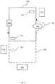
- FIG. 5a simplified overhead view is shown of a facility in which AGV 200 is deployed.
- the facilityincludes a route defined by magnetic tape 128 , and also includes a plurality of processing stations 504 , 508 , 512 (e.g. inventory loading or unloading, tooling stations and the like).
- AGV 200can first be configured to travel along tape 128 without overriding control by augmentation module 204 .
- a first RFID tag 516can represent an instruction to switch from default control to override control (that is, an affirmative determination at block 430 ).
- AGV 200is instructed (via an operational command received at block 410 ) to follow a path 520 .
- the path 520can be defined in the map stored at block 405 as a route of virtual magnetic tape.
- augmentation module 204generates simulated sensor data to control the movement of AGV 200 via control module 120 .
- the map stored in augmentation module 204can also include virtual RFID tags, such as virtual tag 524 , which represents an instruction to stop adjacent to process station 504 .
- subsequent operational commandse.g. from server 330
- can instruct AGV 200still under the indirect control of augmentation module 204 —to travel to, and stop at, process station 508 .
- an operational command indicating a target location along path 520can be sent by server 330 to augmentation module 204 .
- AGV 200will return onto the route defined by tape 128 , at which point control may be returned to control module 120 via a negative determination at block 430 .
- augmentation module 204continues to monitor sensor data, and may detect the presence of an obstacle 528 .
- augmentation module 204may begin the generation of simulated sensor data to depart from tape 128 and guide AGV 200 around obstacle 528 .
- a further RFID tag 536may instruct control module 120 to stop AGV 200 adjacent process station 512 .
- RFID tag 536may be the tag simulated by augmentation module to stop AGV 200 at virtual tag 524 and at process station 508 .
- sensor data received at block 415can be compared with a map stored in memory 324 and containing data representing the locations of existing guiding infrastructure (e.g. tape 128 ). If the comparison reveals that tape 128 is not present where indicated by map 405 , augmentation module 204 can not only override the default control by control module 120 , but can also notify server 330 that the guiding infrastructure has been damaged or removed in the current location of AGV 200 .
- existing guiding infrastructuree.g. tape 128
- the operational commands received at block 410can be teleoperation commands received from a manually-controlled computing device operated by a human pilot of AGV 200 . That is, AGV 200 can be piloted substantially in real-time as a remote-controlled vehicle through the performance of method 400 .
- augmentation module 204may have a direct connection to drive mechanism 112 .
- the performance of method 400may be simplified, in that the conversion of control data to simulated sensor data may no longer be necessary.
- control module 120may be configured to operate in one of two modes—a legacy operation mode as described above, and a relay mode in which control module 120 accepts control data from augmentation module 204 and relays such data to drive mechanism 112 (i.e. without augmentation module 204 being required to generate simulated sensor data).
- augmentation module 204can be configured to automatically determine conversion definitions, rather than have the conversion definitions preconfigured as described above.
- processors 300 or 320 executing their respective applicationsmay be implemented using pre-programmed hardware or firmware elements (e.g., application specific integrated circuits (ASICs), electrically erasable programmable read-only memories (EEPROMs), etc.), or other related components.
- ASICsapplication specific integrated circuits
- EEPROMselectrically erasable programmable read-only memories
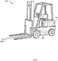
- an AGV 600is illustrated according to certain non-limiting embodiments.
- the AGV 600is shown as a forklift, though other human-operated material-transport vehicles may also be used, such as tuggers and pallet trucks/jacks.
- the forklift as depictedis considered as an AGV 600 for the purposes herein based on the inclusion of a control module (not shown in FIG. 6 ) and a navigation sensor 624 .
- the AGV 600may comprise a human-operated forklift (or other material-transport vehicle) that has been retrofitted with equipment to convert the forklift to an AGV.
- the original equipment of the forkliftmay include the AGV components (e.g. control module, navigation sensors, etc.).
- the navigation sensor 624may be a magnetic field sensor for detecting a strip of magnetic tape 628 placed on the floor of the facility.
- the control moduleis configured to control a drive mechanism of the forklift to correct deviations in the position of the tape 628 from the center of the sensor 124 .
- the control moduleis configured to guide the AGV 600 along the length of the tape 628 .
- the AGV 600further includes an augmentation module 704 coupled to the forklift.
- the augmentation module 704may be coupled to the AGV 600 in any suitable location.
- the AGV 600can include additional components such as a differential drive rotation sensor (e.g. coupled to the drive mechanism of the forklift), and one or more automation interfaces such as a power data interface for providing the augmentation module 704 with data defining a remaining power level (e.g. battery charge) for the AGV 600 .
- the AGV 600can include additional sensors, either mounted on the forklift or on the augmentation module 704 .
- the augmentation module 704can include auxiliary navigation sensors (e.g. additional LiDAR sensors, cameras, GPS sensors, and the like).
Landscapes
- Engineering & Computer Science (AREA)
- Transportation (AREA)
- Structural Engineering (AREA)
- Physics & Mathematics (AREA)
- Aviation & Aerospace Engineering (AREA)
- Automation & Control Theory (AREA)
- General Physics & Mathematics (AREA)
- Remote Sensing (AREA)
- Radar, Positioning & Navigation (AREA)
- Life Sciences & Earth Sciences (AREA)
- Mechanical Engineering (AREA)
- Geology (AREA)
- Civil Engineering (AREA)
- Electromagnetism (AREA)
- Navigation (AREA)
- Control Of Position, Course, Altitude, Or Attitude Of Moving Bodies (AREA)
Abstract
Description
| TABLE 1 |
| Example Conversion Definitions |
| Control Data Type | Sensor to Simulate | Simulated Sensor Data |
| Heading (degrees) | Tape position: A x | |
| heading (mm) | ||
| Action: Stop | RFID Reader | Tag ID: 123 |
| Action: Deploy Tow Pin | RFID Reader | Tag ID: 456 |
Claims (17)
Priority Applications (3)
| Application Number | Priority Date | Filing Date | Title |
|---|---|---|---|
| US15/429,222US10662045B2 (en) | 2016-02-11 | 2017-02-10 | Control augmentation apparatus and method for automated guided vehicles |
| US16/855,788US11167964B2 (en) | 2016-02-11 | 2020-04-22 | Control augmentation apparatus and method for automated guided vehicles |
| US17/462,956US20220055877A1 (en) | 2016-02-11 | 2021-08-31 | Control augmentation apparatus and method for automated guided vehicles |
Applications Claiming Priority (2)
| Application Number | Priority Date | Filing Date | Title |
|---|---|---|---|
| US201662293948P | 2016-02-11 | 2016-02-11 | |
| US15/429,222US10662045B2 (en) | 2016-02-11 | 2017-02-10 | Control augmentation apparatus and method for automated guided vehicles |
Related Child Applications (1)
| Application Number | Title | Priority Date | Filing Date |
|---|---|---|---|
| US16/855,788ContinuationUS11167964B2 (en) | 2016-02-11 | 2020-04-22 | Control augmentation apparatus and method for automated guided vehicles |
Publications (2)
| Publication Number | Publication Date |
|---|---|
| US20170233231A1 US20170233231A1 (en) | 2017-08-17 |
| US10662045B2true US10662045B2 (en) | 2020-05-26 |
Family
ID=59559518
Family Applications (3)
| Application Number | Title | Priority Date | Filing Date |
|---|---|---|---|
| US15/429,222Active2037-11-17US10662045B2 (en) | 2016-02-11 | 2017-02-10 | Control augmentation apparatus and method for automated guided vehicles |
| US16/855,788ActiveUS11167964B2 (en) | 2016-02-11 | 2020-04-22 | Control augmentation apparatus and method for automated guided vehicles |
| US17/462,956AbandonedUS20220055877A1 (en) | 2016-02-11 | 2021-08-31 | Control augmentation apparatus and method for automated guided vehicles |
Family Applications After (2)
| Application Number | Title | Priority Date | Filing Date |
|---|---|---|---|
| US16/855,788ActiveUS11167964B2 (en) | 2016-02-11 | 2020-04-22 | Control augmentation apparatus and method for automated guided vehicles |
| US17/462,956AbandonedUS20220055877A1 (en) | 2016-02-11 | 2021-08-31 | Control augmentation apparatus and method for automated guided vehicles |
Country Status (1)
| Country | Link |
|---|---|
| US (3) | US10662045B2 (en) |
Cited By (1)
| Publication number | Priority date | Publication date | Assignee | Title |
|---|---|---|---|---|
| US20200122858A1 (en)* | 2018-10-22 | 2020-04-23 | Goodrich Corporation | Autonomous system for air cargo end-to-end operations |
Families Citing this family (25)
| Publication number | Priority date | Publication date | Assignee | Title |
|---|---|---|---|---|
| ES2667850T3 (en)* | 2015-09-22 | 2018-05-14 | Bluebotics Sa | Method of retraining and tracking virtual lines for autonomous vehicles |
| WO2018039337A1 (en) | 2016-08-23 | 2018-03-01 | Canvas Technology, Inc. | Autonomous cart for manufacturing and warehouse applications |
| NL2017784B1 (en)* | 2016-11-14 | 2018-05-25 | Ravas Europe B V | Pallet truck |
| US11237545B2 (en)* | 2017-01-09 | 2022-02-01 | Debashis Das | System and method for converting manual industrial machines into automatic industrial machines |
| US10585440B1 (en) | 2017-01-23 | 2020-03-10 | Clearpath Robotics Inc. | Systems and methods for using human-operated material-transport vehicles with fleet-management systems |
| WO2018191818A1 (en) | 2017-04-18 | 2018-10-25 | Clearpath Robotics Inc. | Stand-alone self-driving material-transport vehicle |
| WO2018213931A1 (en) | 2017-05-25 | 2018-11-29 | Clearpath Robotics Inc. | Systems and methods for process tending with a robot arm |
| US11760221B2 (en) | 2017-06-27 | 2023-09-19 | A9.Com, Inc. | Charging systems and methods for autonomous carts |
| US10793369B2 (en) | 2017-07-12 | 2020-10-06 | A9.Com, Inc. | Conveyor system for autonomous robot |
| JP6725063B2 (en)* | 2017-11-28 | 2020-07-15 | Jfeスチール株式会社 | Equipment management system |
| CN109982013A (en)* | 2017-12-28 | 2019-07-05 | 沈阳新松机器人自动化股份有限公司 | A kind of AGV colour band navigation sensor circuit |
| US11305936B2 (en)* | 2018-09-28 | 2022-04-19 | Autoguide, LLC | Commercial logistic facility, configurable modular robotic autonomous guided vehicle, and method therefor |
| CN109911819B (en)* | 2019-03-22 | 2021-06-22 | 杭州昱透实业有限公司 | Balance weight type AGV stacker |
| CN110040194A (en)* | 2019-05-20 | 2019-07-23 | 山东洛杰斯特物流科技有限公司 | Steering wheel and omnidirectional's AGV fork truck based on ring gear transmission |
| DE102019123659A1 (en)* | 2019-09-04 | 2021-03-04 | Sick Ag | Method for creating a map, method for determining a pose of a vehicle, mapping devices and localization devices |
| CN110789606A (en)* | 2019-10-16 | 2020-02-14 | 合肥搬易通科技发展有限公司 | Automatic guiding method for controlling driving direction and position based on all-wheel speed detection and forklift system thereof |
| DE102020206276A1 (en)* | 2020-05-19 | 2021-11-25 | Continental Teves Ag & Co. Ohg | Driverless transport vehicle with improved ease of maintenance |
| US11433920B2 (en) | 2020-05-29 | 2022-09-06 | Robert Bosch Gmbh | Map-based prediction and mitigation of performance limitations for autonomous vehicles |
| US11312393B2 (en)* | 2020-05-29 | 2022-04-26 | Robert Bosch Gmbh | Artificially falsifying sensor data to initiate a safety action for an autonomous vehicle |
| US12122367B2 (en) | 2020-09-10 | 2024-10-22 | Rockwell Automation Technologies, Inc. | Systems and methods for operating one or more self-driving vehicles |
| CN112633804A (en)* | 2020-12-25 | 2021-04-09 | 南京紫津融畅信息科技服务有限公司 | AGV-based vault management method and system |
| US12139384B2 (en)* | 2021-02-26 | 2024-11-12 | Hyster-Yale Materials Handling, Inc. | Structural integrated sensor |
| WO2023154422A1 (en)* | 2022-02-09 | 2023-08-17 | Cyngn, Inc. | Modular sensor system for automated guided vehicles |
| TWI823703B (en)* | 2022-12-06 | 2023-11-21 | 中華汽車工業股份有限公司 | Auxiliary positioning method for unmanned vehicles |
| EP4625286A1 (en)* | 2024-03-28 | 2025-10-01 | Autostore Technology As | System and method for verifying a logical representation |
Citations (5)
| Publication number | Priority date | Publication date | Assignee | Title |
|---|---|---|---|---|
| US8190295B1 (en)* | 2008-05-14 | 2012-05-29 | Sandia Corporation | Apparatus and method for modifying the operation of a robotic vehicle in a real environment, to emulate the operation of the robotic vehicle operating in a mixed reality environment |
| US20150248131A1 (en)* | 2014-03-03 | 2015-09-03 | Google Inc. | Remote Assistance for Autonomous Vehicles in Predetermined Situations |
| US9465388B1 (en)* | 2014-03-03 | 2016-10-11 | Google Inc. | Remote assistance for an autonomous vehicle in low confidence situations |
| US20160327951A1 (en)* | 2015-05-06 | 2016-11-10 | Crown Equipment Corporation | Industrial vehicle for identifying malfunctioning sequenced tag and tag layout for use therewith |
| US9632502B1 (en)* | 2015-11-04 | 2017-04-25 | Zoox, Inc. | Machine-learning systems and techniques to optimize teleoperation and/or planner decisions |
Family Cites Families (57)
| Publication number | Priority date | Publication date | Assignee | Title |
|---|---|---|---|---|
| US5023790A (en) | 1989-02-17 | 1991-06-11 | Whs Robotics | Automatic guided vehicle system |
| US20080183599A1 (en) | 1998-11-18 | 2008-07-31 | Visible Inventory, Inc. | Inventory control and communication system |
| JP3484104B2 (en) | 1998-12-25 | 2004-01-06 | 平田機工株式会社 | Automatic warehouse and automatic warehouse management method |
| JP2001121461A (en) | 1999-10-26 | 2001-05-08 | Denso Corp | Robot system |
| KR100640105B1 (en) | 2001-04-19 | 2006-10-30 | 무라타 기카이 가부시키가이샤 | Automated guided vehicle, automated guided vehicle system and wafer conveyance method |
| JP3991637B2 (en)* | 2001-09-10 | 2007-10-17 | 株式会社明電舎 | Unmanned vehicle |
| SE526913C2 (en) | 2003-01-02 | 2005-11-15 | Arnex Navigation Systems Ab | Procedure in the form of intelligent functions for vehicles and automatic loading machines regarding mapping of terrain and material volumes, obstacle detection and control of vehicles and work tools |
| EP1741044B1 (en) | 2004-03-27 | 2011-09-14 | Harvey Koselka | Autonomous personal service robot |
| US7962192B2 (en) | 2005-09-30 | 2011-06-14 | Restoration Robotics, Inc. | Systems and methods for aligning a tool with a desired location or object |
| US9436184B2 (en) | 2006-06-09 | 2016-09-06 | Amazon Technologies, Inc. | Method and system for transporting inventory items |
| US7873469B2 (en) | 2006-06-19 | 2011-01-18 | Kiva Systems, Inc. | System and method for managing mobile drive units |
| US7693757B2 (en) | 2006-09-21 | 2010-04-06 | International Business Machines Corporation | System and method for performing inventory using a mobile inventory robot |
| JP4576445B2 (en)* | 2007-04-12 | 2010-11-10 | パナソニック株式会社 | Autonomous mobile device and program for autonomous mobile device |
| JP5047709B2 (en) | 2007-07-04 | 2012-10-10 | 株式会社日立製作所 | Moving device, system, moving method, and moving program |
| JP2009031884A (en)* | 2007-07-25 | 2009-02-12 | Toyota Motor Corp | Autonomous mobile object, map information creation method in autonomous mobile object, and moving route identification method in autonomous mobile object |
| TWM348676U (en) | 2008-07-22 | 2009-01-11 | Iner Aec Executive Yuan | Environmental survey robot |
| US7972102B2 (en) | 2008-07-24 | 2011-07-05 | Marine Terminals Corporation | Automated marine container terminal and system |
| US8909466B2 (en) | 2008-08-01 | 2014-12-09 | Environmental Systems Research Institute, Inc. | System and method for hybrid off-board navigation |
| JP5141507B2 (en) | 2008-08-25 | 2013-02-13 | 村田機械株式会社 | Autonomous mobile device |
| US8392065B2 (en)* | 2008-09-11 | 2013-03-05 | Deere & Company | Leader-follower semi-autonomous vehicle with operator on side |
| US8126642B2 (en) | 2008-10-24 | 2012-02-28 | Gray & Company, Inc. | Control and systems for autonomously driven vehicles |
| TWI680928B (en) | 2009-04-10 | 2020-01-01 | 美商辛波提克有限責任公司 | Vertical lift system and method for transferring uncontained case unit to and from a multilevel storage structure |
| FI20095713L (en) | 2009-06-24 | 2010-12-25 | Sandvik Mining & Constr Oy | Determining a driving route to organize automatic control of a mobile mining machine |
| EP2385435A1 (en)* | 2010-04-22 | 2011-11-09 | Danaher Motion Särö AB | A method and a system for gathering data |
| WO2011146259A2 (en) | 2010-05-20 | 2011-11-24 | Irobot Corporation | Mobile human interface robot |
| US8930019B2 (en) | 2010-12-30 | 2015-01-06 | Irobot Corporation | Mobile human interface robot |
| US8965579B2 (en) | 2011-01-28 | 2015-02-24 | Intouch Technologies | Interfacing with a mobile telepresence robot |
| US20130086215A1 (en) | 2011-05-13 | 2013-04-04 | HNTB Holdings, Ltd. | Managing large datasets obtained through a survey-data-acquisition process |
| US8886359B2 (en) | 2011-05-17 | 2014-11-11 | Fanuc Corporation | Robot and spot welding robot with learning control function |
| US8594923B2 (en)* | 2011-06-14 | 2013-11-26 | Crown Equipment Limited | Method and apparatus for sharing map data associated with automated industrial vehicles |
| US8583361B2 (en) | 2011-08-24 | 2013-11-12 | Modular Mining Systems, Inc. | Guided maneuvering of a mining vehicle to a target destination |
| US20130054129A1 (en)* | 2011-08-26 | 2013-02-28 | INRO Technologies Limited | Method and apparatus for using unique landmarks to locate industrial vehicles at start-up |
| WO2013033179A1 (en)* | 2011-08-29 | 2013-03-07 | Crown Equipment Corporation | Vehicular navigation control interface |
| DE102012003690A1 (en) | 2012-02-23 | 2013-08-29 | Kuka Roboter Gmbh | Mobile robot |
| US9463574B2 (en) | 2012-03-01 | 2016-10-11 | Irobot Corporation | Mobile inspection robot |
| US20140040431A1 (en) | 2012-08-06 | 2014-02-06 | General Electric Company | Systems and methods for an opc ua server |
| US8886383B2 (en) | 2012-09-28 | 2014-11-11 | Elwha Llc | Automated systems, devices, and methods for transporting and supporting patients |
| US9804576B2 (en) | 2013-02-27 | 2017-10-31 | Rockwell Automation Technologies, Inc. | Recognition-based industrial automation control with position and derivative decision reference |
| US8965561B2 (en) | 2013-03-15 | 2015-02-24 | Cybernet Systems Corporation | Automated warehousing using robotic forklifts |
| US9141107B2 (en) | 2013-04-10 | 2015-09-22 | Google Inc. | Mapping active and inactive construction zones for autonomous driving |
| JP6117368B2 (en) | 2013-10-11 | 2017-04-19 | 株式会社日立製作所 | Transport vehicle control device and transport vehicle control method |
| US9452531B2 (en) | 2014-02-04 | 2016-09-27 | Microsoft Technology Licensing, Llc | Controlling a robot in the presence of a moving object |
| US9486917B2 (en) | 2014-04-30 | 2016-11-08 | The Boeing Company | Mobile automated assembly tool for aircraft structures |
| US9996976B2 (en) | 2014-05-05 | 2018-06-12 | Avigilon Fortress Corporation | System and method for real-time overlay of map features onto a video feed |
| US9280153B1 (en) | 2014-09-19 | 2016-03-08 | Amazon Technologies, Inc. | Inventory holder load detection and/or stabilization |
| US9824592B2 (en) | 2014-09-22 | 2017-11-21 | Vinveli Unmanned Systems, Inc. | Method and apparatus for ensuring the operation and integrity of a three-dimensional integrated logistical system |
| US9694977B2 (en) | 2014-10-14 | 2017-07-04 | Nextshift Robotics, Inc. | Storage material handling system |
| US9487356B1 (en) | 2015-03-02 | 2016-11-08 | Amazon Technologies, Inc. | Managing low-frequency inventory items in a fulfillment center |
| US9649766B2 (en) | 2015-03-17 | 2017-05-16 | Amazon Technologies, Inc. | Systems and methods to facilitate human/robot interaction |
| US9682481B2 (en) | 2015-10-26 | 2017-06-20 | X Development Llc | Communication of information regarding a robot using an optical identifier |
| US9720415B2 (en)* | 2015-11-04 | 2017-08-01 | Zoox, Inc. | Sensor-based object-detection optimization for autonomous vehicles |
| US9916703B2 (en)* | 2015-11-04 | 2018-03-13 | Zoox, Inc. | Calibration for autonomous vehicle operation |
| US10726381B2 (en) | 2016-04-29 | 2020-07-28 | United Parcel Service Of America, Inc. | Methods for dispatching unmanned aerial delivery vehicles |
| KR102565501B1 (en) | 2016-08-01 | 2023-08-11 | 삼성전자주식회사 | A robotic cleaner, a refrigerator, a system of delivery of a container and a method of delivering and retrieving of a container of the refrigerator using the robotic cleaner |
| US10317119B2 (en) | 2016-08-25 | 2019-06-11 | Amazon Technologiess, Inc. | Transportable climate-controlled units for fulfillment of perishable goods |
| US11097422B2 (en) | 2017-02-07 | 2021-08-24 | Veo Robotics, Inc. | Safety-rated multi-cell workspace mapping and monitoring |
| EP3659077A4 (en) | 2017-07-28 | 2021-05-26 | Nuro, Inc. | FOOD AND BEVERAGE DELIVERY SYSTEM ON AN AUTONOMOUS AND SEMI-AUTONOMOUS VEHICLE |
- 2017
- 2017-02-10USUS15/429,222patent/US10662045B2/enactiveActive
- 2020
- 2020-04-22USUS16/855,788patent/US11167964B2/enactiveActive
- 2021
- 2021-08-31USUS17/462,956patent/US20220055877A1/ennot_activeAbandoned
Patent Citations (5)
| Publication number | Priority date | Publication date | Assignee | Title |
|---|---|---|---|---|
| US8190295B1 (en)* | 2008-05-14 | 2012-05-29 | Sandia Corporation | Apparatus and method for modifying the operation of a robotic vehicle in a real environment, to emulate the operation of the robotic vehicle operating in a mixed reality environment |
| US20150248131A1 (en)* | 2014-03-03 | 2015-09-03 | Google Inc. | Remote Assistance for Autonomous Vehicles in Predetermined Situations |
| US9465388B1 (en)* | 2014-03-03 | 2016-10-11 | Google Inc. | Remote assistance for an autonomous vehicle in low confidence situations |
| US20160327951A1 (en)* | 2015-05-06 | 2016-11-10 | Crown Equipment Corporation | Industrial vehicle for identifying malfunctioning sequenced tag and tag layout for use therewith |
| US9632502B1 (en)* | 2015-11-04 | 2017-04-25 | Zoox, Inc. | Machine-learning systems and techniques to optimize teleoperation and/or planner decisions |
Cited By (4)
| Publication number | Priority date | Publication date | Assignee | Title |
|---|---|---|---|---|
| US20200122858A1 (en)* | 2018-10-22 | 2020-04-23 | Goodrich Corporation | Autonomous system for air cargo end-to-end operations |
| US10994865B2 (en)* | 2018-10-22 | 2021-05-04 | Goodrich Corporation | Autonomous system for air cargo end-to-end operations |
| US11535397B2 (en) | 2018-10-22 | 2022-12-27 | Goodrich Corporation | Autonomous system for air cargo end-to-end operations |
| US11834198B2 (en) | 2018-10-22 | 2023-12-05 | Goodrich Corporation | Autonomous system for air cargo end-to-end operations |
Also Published As
| Publication number | Publication date |
|---|---|
| US20170233231A1 (en) | 2017-08-17 |
| US11167964B2 (en) | 2021-11-09 |
| US20200346907A1 (en) | 2020-11-05 |
| US20220055877A1 (en) | 2022-02-24 |
Similar Documents
| Publication | Publication Date | Title |
|---|---|---|
| US11167964B2 (en) | Control augmentation apparatus and method for automated guided vehicles | |
| US11892853B2 (en) | Vehicle guidance systems and associated methods of use at logistics yards and other locations | |
| CN109160451B (en) | Autonomous navigation unmanned forklift, system and control method | |
| US12298146B2 (en) | Stand-alone self-driving material-transport vehicle | |
| US11537140B2 (en) | Mobile body, location estimation device, and computer program | |
| US20200363212A1 (en) | Mobile body, location estimation device, and computer program | |
| JP2019168942A (en) | Moving body, management device, and moving body system | |
| US20200264616A1 (en) | Location estimation system and mobile body comprising location estimation system | |
| CA2961938A1 (en) | Systems and methods for moving pallets via unmanned motorized unit-guided forklifts | |
| US20180267542A1 (en) | Virtual line-following and retrofit method for autonomous vehicles | |
| US8170731B2 (en) | System and method for detecting reflection with a mobile sensor platform | |
| US11429106B2 (en) | Methods and systems for shifting objects | |
| US20200165083A1 (en) | Transporting device, transporting system, and shelf transporting method | |
| WO2019059307A1 (en) | Moving body and moving body system | |
| JPWO2019054209A1 (en) | Map making system and map making device | |
| KR102446517B1 (en) | Unmanned transport vehicle capable of route driving in indoor and outdoor environments | |
| WO2019194079A1 (en) | Position estimation system, moving body comprising said position estimation system, and computer program | |
| JP2019179497A (en) | Moving body and moving body system | |
| KR20250109431A (en) | Method and apparatus for process control | |
| KR20250101590A (en) | Method and apparatus of virtual control for logistics process | |
| KR20250001482A (en) | Logistics system and controlling apparatus of the same | |
| KR20240169153A (en) | Apparatus and method of collision prediction for logistics robots | |
| KR20250107347A (en) | Method and apparatus of virtual control for logistics robots | |
| Bouguerra et al. | Malta: A system of multiple autonomous trucks for load transportation | |
| KR20250107348A (en) | Method and apparatus for controlling logistics robot |
Legal Events
| Date | Code | Title | Description |
|---|---|---|---|
| STPP | Information on status: patent application and granting procedure in general | Free format text:NON FINAL ACTION MAILED | |
| STPP | Information on status: patent application and granting procedure in general | Free format text:RESPONSE TO NON-FINAL OFFICE ACTION ENTERED AND FORWARDED TO EXAMINER | |
| STPP | Information on status: patent application and granting procedure in general | Free format text:FINAL REJECTION MAILED | |
| STPP | Information on status: patent application and granting procedure in general | Free format text:RESPONSE AFTER FINAL ACTION FORWARDED TO EXAMINER | |
| STPP | Information on status: patent application and granting procedure in general | Free format text:ADVISORY ACTION MAILED | |
| STPP | Information on status: patent application and granting procedure in general | Free format text:DOCKETED NEW CASE - READY FOR EXAMINATION | |
| STPP | Information on status: patent application and granting procedure in general | Free format text:NOTICE OF ALLOWANCE MAILED -- APPLICATION RECEIVED IN OFFICE OF PUBLICATIONS | |
| AS | Assignment | Owner name:CLEARPATH ROBOTICS, INC., CANADA Free format text:ASSIGNMENT OF ASSIGNORS INTEREST;ASSIGNORS:GARIEPY, RYAN CHRISTOPHER;DOBSON, ANDREW;TEBBS, JESSE;AND OTHERS;SIGNING DATES FROM 20160218 TO 20160301;REEL/FRAME:052083/0001 | |
| STPP | Information on status: patent application and granting procedure in general | Free format text:PUBLICATIONS -- ISSUE FEE PAYMENT VERIFIED | |
| STCF | Information on status: patent grant | Free format text:PATENTED CASE | |
| FEPP | Fee payment procedure | Free format text:ENTITY STATUS SET TO UNDISCOUNTED (ORIGINAL EVENT CODE: BIG.); ENTITY STATUS OF PATENT OWNER: LARGE ENTITY | |
| AS | Assignment | Owner name:CLEARPATH ROBOTICS INC., CANADA Free format text:CORRECTIVE ASSIGNMENT TO CORRECT THE THE ASSIGNEE NAME PREVIOUSLY RECORDED AT REEL: 052063 FRAME: 0001. ASSIGNOR(S) HEREBY CONFIRMS THE ASSIGNMENT;ASSIGNORS:GARIEPY, RYAN CHRISTOPHER;DOBSON, ANDREW;TEBBS, JESSE;AND OTHERS;SIGNING DATES FROM 20160218 TO 20160301;REEL/FRAME:065673/0722 | |
| MAFP | Maintenance fee payment | Free format text:PAYMENT OF MAINTENANCE FEE, 4TH YEAR, LARGE ENTITY (ORIGINAL EVENT CODE: M1551); ENTITY STATUS OF PATENT OWNER: LARGE ENTITY Year of fee payment:4 | |
| AS | Assignment | Owner name:ROCKWELL AUTOMATION TECHNOLOGIES, INC., OHIO Free format text:ASSIGNMENT OF ASSIGNORS INTEREST;ASSIGNOR:ROCKWELL AUTOMATION, INC.;REEL/FRAME:067944/0982 Effective date:20240625 Owner name:ROCKWELL AUTOMATION, INC., WISCONSIN Free format text:ASSIGNMENT OF ASSIGNORS INTEREST;ASSIGNOR:CLEARPATH ROBOTICS, INC.;REEL/FRAME:067944/0916 Effective date:20240621 | |
| AS | Assignment | Owner name:ROCKWELL AUTOMATION, INC., WISCONSIN Free format text:CORRECTIVE ASSIGNMENT TO CORRECT THE CONVEYING PARTY'S NAME FROM CLEARPATH ROBOTICS, INC. TO CLEARPATH ROBOTICS INC. (WITHOUT THE COMMA) PREVIOUSLY RECORDED ON REEL 67944 FRAME 916. ASSIGNOR(S) HEREBY CONFIRMS THE ASSIGNMENT;ASSIGNOR:CLEARPATH ROBOTICS INC.;REEL/FRAME:068233/0542 Effective date:20240621 |