US10660798B2 - Devices for protecting vulnerable sites on patients from liquid contamination and related devices, systems, and methods - Google Patents
Devices for protecting vulnerable sites on patients from liquid contamination and related devices, systems, and methodsDownload PDFInfo
- Publication number
- US10660798B2 US10660798B2US15/667,567US201715667567AUS10660798B2US 10660798 B2US10660798 B2US 10660798B2US 201715667567 AUS201715667567 AUS 201715667567AUS 10660798 B2US10660798 B2US 10660798B2
- Authority
- US
- United States
- Prior art keywords
- cover
- region
- patient
- liquid
- protective device
- Prior art date
- Legal status (The legal status is an assumption and is not a legal conclusion. Google has not performed a legal analysis and makes no representation as to the accuracy of the status listed.)
- Active, expires
Links
- 239000007788liquidSubstances0.000titleclaimsabstractdescription57
- 238000011109contaminationMethods0.000titleclaimsabstractdescription45
- 238000000034methodMethods0.000titledescription29
- 230000001681protective effectEffects0.000claimsabstractdescription111
- 239000002313adhesive filmSubstances0.000claimsabstractdescription41
- 230000002093peripheral effectEffects0.000claimsabstractdescription26
- XLYOFNOQVPJJNP-UHFFFAOYSA-NwaterSubstancesOXLYOFNOQVPJJNP-UHFFFAOYSA-N0.000claimsabstractdescription15
- 239000000853adhesiveSubstances0.000claimsabstractdescription10
- 230000001070adhesive effectEffects0.000claimsabstractdescription10
- 238000009423ventilationMethods0.000claimsdescription8
- 239000004599antimicrobialSubstances0.000claimsdescription3
- 206010052428WoundDiseases0.000description7
- 208000027418Wounds and injuryDiseases0.000description7
- 230000008901benefitEffects0.000description7
- 210000000416exudates and transudateAnatomy0.000description7
- 230000000241respiratory effectEffects0.000description6
- 239000000463materialSubstances0.000description5
- 208000015181infectious diseaseDiseases0.000description4
- 230000000903blocking effectEffects0.000description3
- 210000003296salivaAnatomy0.000description3
- 238000000926separation methodMethods0.000description3
- 206010036790Productive coughDiseases0.000description2
- 230000002745absorbentEffects0.000description2
- 239000002250absorbentSubstances0.000description2
- 238000003287bathingMethods0.000description2
- 238000009472formulationMethods0.000description2
- 239000000203mixtureSubstances0.000description2
- 210000003097mucusAnatomy0.000description2
- 210000003802sputumAnatomy0.000description2
- 208000024794sputumDiseases0.000description2
- 210000004243sweatAnatomy0.000description2
- 102000004190EnzymesHuman genes0.000description1
- 108090000790EnzymesProteins0.000description1
- 239000004698PolyethyleneSubstances0.000description1
- 239000004372Polyvinyl alcoholSubstances0.000description1
- BQCADISMDOOEFD-UHFFFAOYSA-NSilverChemical compound[Ag]BQCADISMDOOEFD-UHFFFAOYSA-N0.000description1
- 230000004888barrier functionEffects0.000description1
- 239000008280bloodSubstances0.000description1
- 210000004369bloodAnatomy0.000description1
- 210000003103bodily secretionAnatomy0.000description1
- 230000015556catabolic processEffects0.000description1
- 230000005494condensationEffects0.000description1
- 238000009833condensationMethods0.000description1
- 239000000356contaminantSubstances0.000description1
- 230000000593degrading effectEffects0.000description1
- 239000002274desiccantSubstances0.000description1
- 238000001704evaporationMethods0.000description1
- 230000008020evaporationEffects0.000description1
- 239000004744fabricSubstances0.000description1
- 239000012530fluidSubstances0.000description1
- 239000006260foamSubstances0.000description1
- 229920001477hydrophilic polymerPolymers0.000description1
- 230000002452interceptive effectEffects0.000description1
- 230000007794irritationEffects0.000description1
- 238000012986modificationMethods0.000description1
- 230000004048modificationEffects0.000description1
- 238000012544monitoring processMethods0.000description1
- -1polyethylenePolymers0.000description1
- 229920000573polyethylenePolymers0.000description1
- 229920000642polymerPolymers0.000description1
- 229920002635polyurethanePolymers0.000description1
- 239000004814polyurethaneSubstances0.000description1
- 229920002451polyvinyl alcoholPolymers0.000description1
- 238000006748scratchingMethods0.000description1
- 230000002393scratching effectEffects0.000description1
- 230000002459sustained effectEffects0.000description1
- 210000005166vasculatureAnatomy0.000description1
Images


Classifications
- A—HUMAN NECESSITIES
- A61—MEDICAL OR VETERINARY SCIENCE; HYGIENE
- A61F—FILTERS IMPLANTABLE INTO BLOOD VESSELS; PROSTHESES; DEVICES PROVIDING PATENCY TO, OR PREVENTING COLLAPSING OF, TUBULAR STRUCTURES OF THE BODY, e.g. STENTS; ORTHOPAEDIC, NURSING OR CONTRACEPTIVE DEVICES; FOMENTATION; TREATMENT OR PROTECTION OF EYES OR EARS; BANDAGES, DRESSINGS OR ABSORBENT PADS; FIRST-AID KITS
- A61F13/00—Bandages or dressings; Absorbent pads
- A61F13/00051—Accessories for dressings
- A61F13/00063—Accessories for dressings comprising medicaments or additives, e.g. odor control, PH control, debriding, antimicrobic
- A—HUMAN NECESSITIES
- A61—MEDICAL OR VETERINARY SCIENCE; HYGIENE
- A61F—FILTERS IMPLANTABLE INTO BLOOD VESSELS; PROSTHESES; DEVICES PROVIDING PATENCY TO, OR PREVENTING COLLAPSING OF, TUBULAR STRUCTURES OF THE BODY, e.g. STENTS; ORTHOPAEDIC, NURSING OR CONTRACEPTIVE DEVICES; FOMENTATION; TREATMENT OR PROTECTION OF EYES OR EARS; BANDAGES, DRESSINGS OR ABSORBENT PADS; FIRST-AID KITS
- A61F13/00—Bandages or dressings; Absorbent pads
- A61F13/02—Adhesive bandages or dressings
- A61F13/0203—Adhesive bandages or dressings with fluid retention members
- A—HUMAN NECESSITIES
- A61—MEDICAL OR VETERINARY SCIENCE; HYGIENE
- A61F—FILTERS IMPLANTABLE INTO BLOOD VESSELS; PROSTHESES; DEVICES PROVIDING PATENCY TO, OR PREVENTING COLLAPSING OF, TUBULAR STRUCTURES OF THE BODY, e.g. STENTS; ORTHOPAEDIC, NURSING OR CONTRACEPTIVE DEVICES; FOMENTATION; TREATMENT OR PROTECTION OF EYES OR EARS; BANDAGES, DRESSINGS OR ABSORBENT PADS; FIRST-AID KITS
- A61F13/00—Bandages or dressings; Absorbent pads
- A61F13/12—Bandages or dressings; Absorbent pads specially adapted for the head or neck
- A—HUMAN NECESSITIES
- A61—MEDICAL OR VETERINARY SCIENCE; HYGIENE
- A61B—DIAGNOSIS; SURGERY; IDENTIFICATION
- A61B46/00—Surgical drapes
- A61B46/20—Surgical drapes specially adapted for patients
- A61B2046/205—Adhesive drapes
- A—HUMAN NECESSITIES
- A61—MEDICAL OR VETERINARY SCIENCE; HYGIENE
- A61F—FILTERS IMPLANTABLE INTO BLOOD VESSELS; PROSTHESES; DEVICES PROVIDING PATENCY TO, OR PREVENTING COLLAPSING OF, TUBULAR STRUCTURES OF THE BODY, e.g. STENTS; ORTHOPAEDIC, NURSING OR CONTRACEPTIVE DEVICES; FOMENTATION; TREATMENT OR PROTECTION OF EYES OR EARS; BANDAGES, DRESSINGS OR ABSORBENT PADS; FIRST-AID KITS
- A61F15/00—Auxiliary appliances for wound dressings; Dispensing containers for dressings or bandages
- A61F15/004—Bandage protectors
- A—HUMAN NECESSITIES
- A61—MEDICAL OR VETERINARY SCIENCE; HYGIENE
- A61F—FILTERS IMPLANTABLE INTO BLOOD VESSELS; PROSTHESES; DEVICES PROVIDING PATENCY TO, OR PREVENTING COLLAPSING OF, TUBULAR STRUCTURES OF THE BODY, e.g. STENTS; ORTHOPAEDIC, NURSING OR CONTRACEPTIVE DEVICES; FOMENTATION; TREATMENT OR PROTECTION OF EYES OR EARS; BANDAGES, DRESSINGS OR ABSORBENT PADS; FIRST-AID KITS
- A61F15/00—Auxiliary appliances for wound dressings; Dispensing containers for dressings or bandages
- A61F15/008—Appliances for wound protecting, e.g. avoiding contact between wound and bandage
- A—HUMAN NECESSITIES
- A61—MEDICAL OR VETERINARY SCIENCE; HYGIENE
- A61F—FILTERS IMPLANTABLE INTO BLOOD VESSELS; PROSTHESES; DEVICES PROVIDING PATENCY TO, OR PREVENTING COLLAPSING OF, TUBULAR STRUCTURES OF THE BODY, e.g. STENTS; ORTHOPAEDIC, NURSING OR CONTRACEPTIVE DEVICES; FOMENTATION; TREATMENT OR PROTECTION OF EYES OR EARS; BANDAGES, DRESSINGS OR ABSORBENT PADS; FIRST-AID KITS
- A61F13/00—Bandages or dressings; Absorbent pads
- A61F2013/00089—Wound bandages
- A61F2013/00272—Wound bandages protection of the body or articulation
Definitions
- the present technologyis related to protective devices for medical applications.
- at least some embodimentsare related to devices for protecting vulnerable sites (e.g., percutaneous sites) on patients from respiratory exudates and/or other types of liquid contamination.
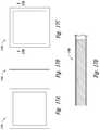
- FIGS. 1A, 1B, and 1Care a front (i.e., skin-contact) side view, an edge view, and a back view, respectively, of a protective device configured in accordance with an embodiment of the present technology.
- FIG. 1Dis a cross-sectional end view of the protective device shown in FIGS. 1A-1C taken along the line 1 D- 1 D in FIG. 1C in a non-deployed state.
- FIG. 1Eis a cross-sectional end view of the protective device shown in FIGS. 1A-1C taken along the line 1 E- 1 E in FIG. 1C in a deployed state against a patient's skin.
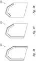
- FIGS. 2-4are perspective views illustrating protective devices similar to the protective device of FIGS. 1A-1D , but having different suitable peripheral coverage of adhesive films and liquid-absorbing elements configured in accordance with embodiments of the present technology.
- FIGS. 5A, 5B, and 5Care a front (i.e., skin-contact) side view, an edge view, and a back view, respectively, of a protective device configured in accordance with an embodiment of the present technology.
- FIG. 5Dis a cross-sectional end view of the protective device shown in FIGS. 5A-5C taken along the line 5 D- 5 D in FIG. 5C .
- FIGS. 6-8are perspective views illustrating protective devices similar to the protective device of FIGS. 5A-5D , but having different suitable peripheral coverage of adhesive films and liquid-absorbing elements configured in accordance with embodiments of the present technology.
- FIGS. 9A, 9B, and 9Care a front (i.e., skin-contact) side view, an edge view, and a back view, respectively, of a protective device configured in accordance with an embodiment of the present technology.
- FIG. 9Dis a cross-sectional end view of the protective device shown in FIGS. 9A-9C taken along the line 9 D- 9 D in FIG. 9C .
- FIGS. 10-12are perspective views illustrating protective devices similar to the protective device of FIGS. 9A-9D , but having different suitable peripheral coverage of adhesive films and liquid-absorbing elements configured in accordance with embodiments of the present technology.
- FIGS. 13A, 13B, and 13Care a front (i.e., skin-contact) side view, an edge view, and a back view, respectively, of a protective device configured in accordance with an embodiment of the present technology.
- FIG. 13Dis a cross-sectional end view of the protective device shown in FIGS. 13A-13C taken along the line 13 D- 13 D in FIG. 13C .
- FIGS. 14-16are perspective views illustrating protective devices similar to the protective device of FIGS. 13A-13D , but having different suitable peripheral coverage of adhesive films and liquid-absorbing elements configured in accordance with embodiments of the present technology.
- FIGS. 17A, 17B, and 17Care a front (i.e., skin-contact) side view, an edge view, and a back view, respectively, of a protective device configured in accordance with an embodiment of the present technology.
- FIG. 17Dis a cross-sectional end view of the protective device shown in FIGS. 17A-17C taken along the line 17 D- 17 D in FIG. 17C .
- FIGS. 18-20are perspective views illustrating protective devices similar to the protective device of FIGS. 17A-17D , but having different suitable peripheral coverage of adhesive films and liquid-absorbing elements configured in accordance with embodiments of the present technology.
- FIGS. 21A, 21B, and 21Care a front (i.e., skin-contact) side view, an edge view, and a back view, respectively, of a protective device configured in accordance with an embodiment of the present technology.
- FIG. 21Dis a cross-sectional end view of the protective device shown in FIGS. 21A-21C taken along the line 21 D- 21 D in FIG. 21C .
- FIGS. 22-24are perspective views illustrating protective devices similar to the protective device of FIGS. 21A-21D , but having different suitable peripheral coverage of adhesive films and liquid-absorbing elements configured in accordance with embodiments of the present technology.
- FIGS. 25A, 25B, and 25Care a front (i.e., skin-contact) side view, an edge view, and a back view, respectively, of a protective device configured in accordance with an embodiment of the present technology.
- FIG. 25Dis a cross-sectional end view of the protective device shown in FIGS. 25A-25C taken along the line 25 D- 25 D in FIG. 25C .
- FIGS. 26-28are perspective views illustrating protective devices similar to the protective device of FIGS. 25A-25D , but having different suitable peripheral coverage of adhesive films and liquid-absorbing elements configured in accordance with embodiments of the present technology.
- FIGS. 29A, 29B, and 29Care a front (i.e., skin-contact) side view, an edge view, and a back view, respectively, of a protective device configured in accordance with an embodiment of the present technology.
- FIG. 29Dis a cross-sectional end view of the protective device shown in FIGS. 29A-29C taken along the line 29 D- 29 D in FIG. 29C .
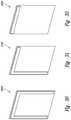
- FIGS. 30-32are perspective views illustrating protective devices similar to the protective device of FIGS. 29A-29D , but having different suitable peripheral coverage of adhesive films and liquid-absorbing elements configured in accordance with embodiments of the present technology.
- FIGS. 33A, 33B, and 33Care a front (i.e., skin-contact) side view, an edge view, and a back view, respectively, of a protective device configured in accordance with an embodiment of the present technology.
- FIG. 33Dis a cross-sectional end view of the protective device shown in FIGS. 33A-33C taken along the line 33 D- 33 D in FIG. 33C .
- FIGS. 34-36are perspective views illustrating protective devices similar to the protective device of FIGS. 33A-33D , but having different suitable peripheral coverage of adhesive films and liquid-absorbing elements configured in accordance with embodiments of the present technology.
- FIG. 37is a flow chart illustrating a protective method 3700 in accordance with an embodiment of the present technology.
- embodiments of the present technologycan have different configurations, components, and/or procedures than those shown or described herein.
- embodiments of the present technologycan have configurations, components, and/or procedures in addition to those shown or described herein and that these and other embodiments can be without several of the configurations, components, and/or procedures shown or described herein without deviating from the present technology.
- a vulnerable site on a patient's torso or limbmay be exposed to sweat, bathing runoff (e.g., from a sponge bath), spilled fluids, and/or other types of liquid contamination.
- Conventional dressingstypically are ill suited for protecting vulnerable sites from liquid contamination.
- many conventional dressingsare designed primarily to reduce or prevent egress of liquid exudates (e.g., blood) from a wound, not to protect the wound from external sources of liquid contamination.
- these and other conventional dressingsmay absorb liquid contamination, the absorbed liquid contamination typically is held in sustained contact with an adhesive and/or with the patient's skin. This can cause irritation, adhesive failure, and/or inadequate ventilation and/or have other undesirable consequences.
- enzymes in salivacan accelerate the breakdown of skin, thereby causing conventional dressings adhesively attached to skin to detach prematurely and/or contaminating a wound site.
- a protective deviceconfigured in accordance with a particular embodiment includes a liquid-impermeable cover configured to extend over a vulnerable site on a patient and a liquid-absorbing element configured to absorb liquid contamination at and/or approaching an outer edge portion of an adhesive bond between the cover and the patient's skin.
- the liquid-absorbing elementcan hold the liquid contamination away from the vulnerable site and the cover can act as a complete or partial barrier to liquid contamination not held by the liquid-absorbing element.
- the liquid-absorbing elementcan help to protect the adhesive bond from degrading in the presence of liquid contamination.
- FIGS. 1A, 1B, and 1Care a front (i.e., skin-contact) side view, an edge view, and a back view, respectively, of a protective device 100 configured in accordance with an embodiment of the present technology.
- FIG. 1Dis a cross-sectional end view of the protective device 100 taken along the line 1 D- 1 D in FIG. 1C in a non-deployed state.
- FIG. 1Eis a cross-sectional end view of the protective device 100 taken along the line 1 E- 1 E in FIG. 1C in a deployed state against a patient's skin 101 .
- the protective device 100can include a cover 102 , an adhesive film 104 , and a liquid-absorbing element 106 .
- the cover 102can have a first (e.g., central) region 102 a and a second (e.g., peripheral) region 102 b extending around a perimeter of the first region 102 a .
- the cover 102can be configured to be operably positioned on a human patient such that the first region 102 a extends over a vulnerable site (not shown) on the patient and the second region 102 b extends over an area on the patient peripheral to the vulnerable site.
- the cover 102is flexible and configured to drape over a vulnerable site, such as to accommodate the dimensionality of a percutaneous device (e.g., a peripheral cannula extending into a patient's vasculature).
- the first region 102 acan be a region of a sheet of flexible polymeric material, such as flexible polyurethane, flexible polyethylene, or another suitable flexible polymeric material.
- the cover 102can be less flexible.
- the first region 102 acan be a region of a three-dimensional shell that is at least generally rigid and configured to at least partially encase a three-dimensional space adjacent to a vulnerable site.
- the first region 102 acan be opaque, transparent (e.g., to allow a vulnerable site or a percutaneous device at a vulnerable site to be visually monitored), or otherwise translucent.
- the protective device 100can be configured to protect the vulnerable site from liquid (e.g., non-aerosolized liquid and aerosolized liquid) and particulate contamination.
- the first region 102 a , the second region 102 b , or bothcan be at least generally impermeable to liquid water.
- the protective device 100protects a percutaneous device (not shown) that is positioned at least proximate to a patient's neck and the protective device 100 reduces the probability that an infection will develop at the vulnerable site by protecting the vulnerable site from respiratory exudates (e.g., sputum, mucus, and/or saliva) and other sources of contamination.
- the protective device 100can be used at other suitable anatomical locations.
- the protective device 100can be used to protect a vulnerable site that does not include a percutaneous device, such as a dressed wound, an undressed wound, or a stoma without an associated percutaneous device. Still further, the protective device 100 can be used to protect a vulnerable site from liquid contamination other than respiratory exudates, such as sweat, bathing runoff, or spilled liquids. Still further, in addition to or instead of reducing the probability that an infection will develop at a vulnerable site, the protective device 100 can address a different type of vulnerability, such as susceptibility to shifting of a percutaneous device relative to a patient, susceptibility to inadvertent scratching, or another suitable type of vulnerability.
- the cover 102 and components of the cover 102individually can have first side 102 c facing toward the patient and a second side 102 d facing away from the patient. Furthermore, the cover 102 can have an outer edge portion 102 e extending between the first and second sides 102 c , 102 d .
- the adhesive film 104can be attached to the cover 102 directly or indirectly and can have an inner edge portion 104 a toward the first region 102 a and an outer edge portion 104 b away from the first region 102 a .
- the adhesive film 104can be disposed along the first side 102 c of the second region 102 b of the cover 102 .
- the adhesive film 104can be configured to form an adhesive bond 107 ( FIG. 1E ) between the second region 102 b and the patient's skin 101 .
- the bond 107can have an inner edge portion 107 a positioned toward a vulnerable site and an outer edge portion 107 b positioned away from the vulnerable site.
- the bond 107can be a direct bond between the second region 102 b and the patient or an indirect bond. Furthermore, in some embodiments, the outer edge portion 107 b of the bond 107 is aligned with the outer edge portion 102 e of the cover 102 . In other embodiments, the outer edge portion 107 b of the bond 107 can be inset (e.g., toward the vulnerable site) relative to the outer edge portion 102 e of the cover 102 .
- the adhesive film 104can be configured such that the outer edge portion 102 e of the cover 102 is positioned at least about 0.5 centimeter or at least another suitable distance further from the vulnerable site than the outer edge portion 107 b of the bond 107 when the cover 102 is operably positioned on a patient.
- the bond 107at least generally blocks direct air exchange between the vulnerable site and the liquid-absorbing element 106 . This can be useful, for example, to enhance separation between the vulnerable site and liquid contaminants within the liquid-absorbing element 106 .
- the vulnerable sitecan be open to air exchange with the liquid-absorbing element 106 .
- the bond 107can be between the liquid-absorbing element 106 and the patient's skin 101 and the cover 102 can be attached to the patient via both the liquid-absorbing element 106 and the bond 107 rather than via the bond 107 only.
- the adhesive film 104can extend around all or a portion of the perimeter of the first region 102 a .
- the cover 102includes a third region (not shown) at a portion of the perimeter of the first region 102 a along which the adhesive film 104 does not extend.
- the adhesive film 104can extend around a percentage of the perimeter of the first region 102 a of the cover 102 from about 5% to about 95%, from about 10% to about 95%, from about 15% to about 95%, or within another suitable range.
- the third regioncan be configured to allow ventilation of a vulnerable site when the cover 102 is operably positioned on a patient.
- Such ventilationcan reduce or prevent undue condensation on the first side 102 c of the cover 102 even when the first region 102 a of the cover 102 is impermeable to water vapor.
- the adhesive film 104can extend around the entire perimeter of the first region 102 a .
- the first region 102 a of the cover 102can be permeable to water vapor, the cover 102 can be configured to allow ventilation in another suitable manner, or the cover 102 can be configured to leave a vulnerable site unventilated.
- the cover 102 , the adhesive film 104 , or another suitable component of the device 100includes an active or passive vent (not shown), such as a perforation, a fenestration, a filtered opening, or a baffled opening.
- the ventfor example, can be configured to allow water vapor to escape from the vulnerable site without unduly interfering with the ability of the cover 102 to exclude liquid contamination from the vulnerable site.
- the liquid-absorbing element 106can be attached to the cover 102 directly or indirectly. In some embodiments, at least a portion of the liquid-absorbing element 106 is disposed along the second side 102 d of the cover 102 (e.g., along the second side 102 d of the second region 102 b of the cover 102 ) such that the cover 102 is positioned between at least a portion of the liquid-absorbing element 106 and a patient when the cover 102 is operably positioned on the patient.
- the liquid-absorbing element 106can be disposed along the first side 102 c of the cover 102 , such that at least a portion of the liquid-absorbing element 106 is positioned between the cover 102 and a patient when the cover 102 is operably positioned on the patient. In sill other embodiments, the liquid-absorbing element 106 can be disposed partially along the first side 102 c of the cover 102 and partially along the second side 102 d of the cover 102 . The position of the liquid-absorbing element 106 relative to the cover 102 can affect how liquid contamination within the liquid-absorbing element 106 is held.
- positioning the liquid-absorbing element 106 between the cover 102 and the patientcan, in at least some cases, enhance separation between the liquid contamination and the bond 107 .
- positioning the cover 102 between the liquid-absorbing element 106 and the patientcan, in at least some cases, enhance separation between the liquid contamination and the patient's skin 101 and/or accelerate evaporation of the liquid contamination, such as by exposing a relatively large portion of the liquid-absorbing element 106 to the atmosphere.
- the liquid-absorbing element 106can be configured to absorb liquid contamination at the outer edge portion 107 b of the bond 107 and/or liquid contamination approaching the outer edge portion 107 b of the bond 107 when the cover 102 is operably positioned on a patient.
- the liquid-absorbing element 106can be configured to wick liquid contamination away from the outer edge portion 107 b of the bond 107 .
- the liquid-absorbing element 106can have an inner edge portion 106 a positioned toward the bond 107 and an outer edge portion 106 b positioned away from the bond 107 . As shown in FIGS.
- the liquid-absorbing element 106can be positioned further from the vulnerable site than the outer edge portion 107 b of the bond 107 when the cover 102 is operably positioned on the patient. Furthermore, in some embodiments, the outer edge portion 102 e of the cover 102 can be positioned closer to the vulnerable site than the outer edge portion 106 b of the liquid-absorbing element 106 . In other embodiments, the outer edge portion 102 e of the cover 102 can be positioned further from the vulnerable site than the outer edge portion 106 b of the liquid-absorbing element 106 . For example, the outer edge portion 102 e of the cover 102 can be configured to drape over the outer edge portion 106 b of the liquid-absorbing element 106 when the cover 102 is operably positioned on the patient.
- the liquid-absorbing element 106can be an elongate strip of absorbent material or have another suitable form.
- the liquid-absorbing element 106can have an average dimension (e.g., thickness) perpendicular to an associated skin surface greater than about 2 millimeters (e.g., from about 2 millimeters to about 50 millimeters), greater than about 5 millimeters (e.g., from about 5 millimeters to about 50 millimeters), greater than about 10 millimeters (e.g., from about 10 millimeters to about 50 millimeters), greater than another suitable threshold or within another suitable range.
- Suitable materials and material classes for the liquid-absorbing element 106include, for example, porous media (e.g., fabrics and open-cell foams), polymers (e.g., polyvinyl alcohol), hydrophilic polymers, and desiccants, among others.
- the liquid-absorbing element 106is capable of absorbing at least about five times (e.g., from about 5 times to about 100 times) its weight in liquid water, such as at least about 10 times (e.g., from about 10 times to about 100 times) its weight in liquid water.
- the liquid-absorbing element 106can have other suitable absorbent properties.
- the liquid-absorbing element 106can include an antimicrobial agent (e.g., colloidal silver), which can add another layer of protection against infection.
- FIGS. 2, 3 and 4are perspective views illustrating, respectively, protective devices 200 , 300 and 400 that are similar to the protective device 100 , but have different suitable peripheral coverage of adhesive films and liquid-absorbing elements.
- FIGS. 5A-5Dillustrate a protective device 500 similar to the protective device 100 , but having a different suitable shape.
- FIGS. 6, 7 and 8are perspective views illustrating, respectively, protective devices 600 , 700 and 800 that are similar to the protective device 500 , but have different suitable peripheral coverage of adhesive films and liquid-absorbing elements.
- FIGS. 9A-9Dillustrate a protective device 900 similar to the protective device 100 , but having a different suitable shape.
- FIG 10, 11 and 12are perspective views illustrating, respectively, protective devices 1000 , 1100 and 1200 that are similar to the protective device 900 , but have different suitable peripheral coverage of adhesive films and liquid-absorbing elements.
- a variety of other suitable shapes and peripheral coverageare also possible. For example, different shapes can be selected based on anatomical differences among patients, different characteristics of different types of vulnerable sites to be protected, and/or different dimensions of percutaneous devices.
- the peripheral coveragecan be selected, for example, based on these factors alone or together with different demands for ventilation and/or different demands for accessibility of vulnerable sites.
- FIGS. 13A-13Dillustrate a protective device 1300 similar to the protective device 100 , but having a first adhesive film 1302 configured to be positioned between a liquid-absorbing element 1304 and a patient (not shown) as well as a second adhesive film 1306 positioned between the liquid-absorbing element 1304 and an associated cover.
- the liquid-absorbing element 1304can have an inner edge portion 1304 a toward a vulnerable site (not shown) and an outer edge portion 1304 b away from the vulnerable site.
- FIGS. 14, 15 and 16are perspective views illustrating, respectively, protective devices 1400 , 1500 and 1600 that are similar to the protective device 1300 , but have different suitable peripheral coverage of adhesive films and liquid-absorbing elements.
- FIGS. 17A-17Dillustrate a protective device 1700 similar to the protective device 1300 , but having a different suitable shape.
- FIGS. 18, 19 and 20are perspective views illustrating, respectively, protective devices 1800 , 1900 and 2000 that are similar to the protective device 1700 , but have different suitable peripheral coverage of adhesive films and liquid-absorbing elements.
- FIGS. 21A-21Dillustrate a protective device 2100 similar to the protective device 1300 , but having a different suitable shape.
- FIGS. 22, 23 and 24are perspective views illustrating, respectively, protective devices 2200 , 2300 and 2400 that are similar to the protective device 2100 , but have different suitable peripheral coverage of adhesive films and liquid-absorbing elements.
- FIGS. 25A-25Dillustrate a protective device 2500 similar to the protective device 1300 , but having the first adhesive film 1302 , the liquid-absorbing element 1304 , and the second adhesive film 1306 inset relative to the outer edge portion 102 e of the cover 102 such that a flap 2502 extends over the outer edge portion 1304 b of the liquid-absorbing element 1304 .
- FIGS. 26, 27 and 28are perspective views illustrating, respectively, protective devices 2600 , 2700 and 2800 that are similar to the protective device 2500 , but have different suitable peripheral coverage of adhesive films and liquid-absorbing elements.
- FIGS. 29A-29Dillustrate a protective device 2900 similar to the protective device 2500 , but having a different suitable shape.
- FIGS. 30, 31 and 32are perspective views illustrating, respectively, protective devices 3000 , 3100 and 3200 that are similar to the protective device 2900 , but have different suitable peripheral coverage of adhesive films and liquid-absorbing elements.
- FIGS. 33A-33Dillustrate a protective device 3300 similar to the protective device 2500 , but having a different suitable shape.
- FIGS. 34, 35 and 36are perspective views illustrating, respectively, protective devices 3400 , 3500 and 3600 that are similar to the protective device 3300 , but have different suitable peripheral coverage of adhesive films and liquid-absorbing elements.
- FIG. 37is a flow chart illustrating a protective method 3700 in accordance with an embodiment of the present technology.
- the method 3700can include positioning the first region 102 a of the cover 102 over a vulnerable site on a human patient (block 3702 ) and positioning the second region 102 b of the cover 102 between the vulnerable site and an actual or potential source of liquid contamination (block 3704 ).
- the vulnerable sitecan be at least proximate to the patient's neck and the second region 102 b of the cover 102 can be positioned between the vulnerable site and the patient's mouth and/or nose.
- the method 3700can further include forming the adhesive bond 107 between the second region 102 b of the cover 102 and the patient (block 3706 ). In some embodiments, this includes forming the bond 107 around the entire perimeter of the first region 102 a of the cover 102 . In other embodiments, this can include forming the bond 107 around a suitable percentage of a perimeter of the first region 102 a of the cover 102 , such as from about 10% to about 90% of the perimeter of the first region 102 a of the cover 102 .
- the method 3700can include absorbing liquid contamination (e.g., respiratory exudates from the patient's mouth and/or nose) at the outer edge portion 107 b of the bond 107 and/or liquid contamination approaching the outer edge portion 107 b of the bond 107 using the liquid-absorbing element 106 (block 3708 ).
- the method 3700can include wicking liquid contamination away from the outer edge portion 107 b of the bond 107 and into the liquid-absorbing element 106 .
- the liquid contaminationis absorbed via an outwardly projecting portion of the liquid-absorbing element 106 positioned further from the vulnerable site than the outer edge portion 107 b of the bond 107 .
- the method 3700can include at least generally blocking direct exchange between air in contact with the vulnerable site at one side of the bond 107 and air in contact with liquid contamination within the liquid-absorbing element 106 at an opposite side of the bond 107 (block 3710 ).
- the method 3700can also include other suitable operations.
- the method 3700can include loosely positioning the first region 102 a of the cover 102 over a percutaneous device at the vulnerable site.
- the method 3700can include tightly positioning the first region 102 a of the cover 102 over a percutaneous device at the vulnerable site, such as to at least partially secure a position of the percutaneous device relative to the patient.
- the method 3700can include visually monitoring the vulnerable site through the first region 102 a of the cover 102 .
- the method 3700can include moving the first region 102 a of the cover 102 to at least partially expose the vulnerable site without disrupting the bond 107 .
- the method 3700can include at least generally blocking direct contact between liquid contamination within the liquid-absorbing element 106 at one side of the cover 102 and the patient at an opposite side of the cover 102 , such as when the liquid-absorbing element 106 is disposed along the second side 102 d of the second region 102 b of the cover 102 .
- the method 3700can include ventilating the vulnerable site through a gap between the patient and a third region of the cover 102 at a portion of the perimeter of the first region 102 a of the cover 102 around which the bond 107 is not formed.
- a method in accordance with a particular embodimentincludes positioning a first region of a cover over a vulnerable site on a human patient, positioning a second region of the cover between the vulnerable site and an actual or potential source of liquid contamination, forming an adhesive bond between the second region of the cover and the patient, absorbing liquid contamination at an outer edge portion of the bond and/or liquid contamination approaching the outer edge portion of the bond using a liquid-absorbing element attached to the cover, and at least generally blocking direct exchange between air in contact with the vulnerable site at one side of the bond and air in contact with liquid contamination within the liquid-absorbing element at an opposite side of the bond.
- a method in accordance with another embodimentincludes instructing such a method.
Landscapes
- Health & Medical Sciences (AREA)
- Public Health (AREA)
- Engineering & Computer Science (AREA)
- Heart & Thoracic Surgery (AREA)
- Vascular Medicine (AREA)
- Life Sciences & Earth Sciences (AREA)
- Animal Behavior & Ethology (AREA)
- Biomedical Technology (AREA)
- Veterinary Medicine (AREA)
- General Health & Medical Sciences (AREA)
- Chemical & Material Sciences (AREA)
- Medicinal Chemistry (AREA)
- Otolaryngology (AREA)
- Materials For Medical Uses (AREA)
- Infusion, Injection, And Reservoir Apparatuses (AREA)
- Medicinal Preparation (AREA)
Abstract
Description
Claims (20)
Priority Applications (1)
| Application Number | Priority Date | Filing Date | Title |
|---|---|---|---|
| US15/667,567US10660798B2 (en) | 2013-03-26 | 2017-08-02 | Devices for protecting vulnerable sites on patients from liquid contamination and related devices, systems, and methods |
Applications Claiming Priority (3)
| Application Number | Priority Date | Filing Date | Title |
|---|---|---|---|
| US201361805483P | 2013-03-26 | 2013-03-26 | |
| US14/225,268US9724242B2 (en) | 2013-03-26 | 2014-03-25 | Devices for protecting vulnerable sites on patients from liquid contamination and related devices, systems, and methods |
| US15/667,567US10660798B2 (en) | 2013-03-26 | 2017-08-02 | Devices for protecting vulnerable sites on patients from liquid contamination and related devices, systems, and methods |
Related Parent Applications (1)
| Application Number | Title | Priority Date | Filing Date |
|---|---|---|---|
| US14/225,268ContinuationUS9724242B2 (en) | 2013-03-26 | 2014-03-25 | Devices for protecting vulnerable sites on patients from liquid contamination and related devices, systems, and methods |
Publications (2)
| Publication Number | Publication Date |
|---|---|
| US20180008472A1 US20180008472A1 (en) | 2018-01-11 |
| US10660798B2true US10660798B2 (en) | 2020-05-26 |
Family
ID=51621531
Family Applications (2)
| Application Number | Title | Priority Date | Filing Date |
|---|---|---|---|
| US14/225,268Expired - Fee RelatedUS9724242B2 (en) | 2013-03-26 | 2014-03-25 | Devices for protecting vulnerable sites on patients from liquid contamination and related devices, systems, and methods |
| US15/667,567Active2035-01-29US10660798B2 (en) | 2013-03-26 | 2017-08-02 | Devices for protecting vulnerable sites on patients from liquid contamination and related devices, systems, and methods |
Family Applications Before (1)
| Application Number | Title | Priority Date | Filing Date |
|---|---|---|---|
| US14/225,268Expired - Fee RelatedUS9724242B2 (en) | 2013-03-26 | 2014-03-25 | Devices for protecting vulnerable sites on patients from liquid contamination and related devices, systems, and methods |
Country Status (1)
| Country | Link |
|---|---|
| US (2) | US9724242B2 (en) |
Families Citing this family (7)
| Publication number | Priority date | Publication date | Assignee | Title |
|---|---|---|---|---|
| US9724242B2 (en) | 2013-03-26 | 2017-08-08 | Cenorin, Llc | Devices for protecting vulnerable sites on patients from liquid contamination and related devices, systems, and methods |
| USD842461S1 (en) | 2017-08-10 | 2019-03-05 | Duke University | Sleeve for securing intravenous tubes on a patient |
| USD829895S1 (en) | 2017-08-10 | 2018-10-02 | Duke University | Vest for securing intravenous tubes on a patient |
| US20190321233A1 (en)* | 2018-04-20 | 2019-10-24 | 2G Medical, LLC | Temporary Barrier to Shield an Exposed Feature On a Person |
| USD957651S1 (en) | 2020-02-04 | 2022-07-12 | Ahmad Williams | Bandage with elevated center |
| USD1083118S1 (en) | 2023-01-13 | 2025-07-08 | Deroyal Industries, Inc. | Incision dressing |
| USD1085427S1 (en) | 2023-01-13 | 2025-07-22 | Deroyal Industries, Inc. | Incision dressing |
Citations (50)
| Publication number | Priority date | Publication date | Assignee | Title |
|---|---|---|---|---|
| US4181127A (en) | 1978-06-29 | 1980-01-01 | Johnson & Johnson | Balanced environment wound dressing |
| US4678462A (en) | 1986-04-15 | 1987-07-07 | Vaillancourt Vincent L | Sterile catheter securement device |
| US4704177A (en) | 1984-07-06 | 1987-11-03 | Manresa, Inc. | Medicator securing device |
| US4917112A (en) | 1988-08-22 | 1990-04-17 | Kalt Medical Corp. | Universal bandage with transparent dressing |
| US5074847A (en) | 1989-05-01 | 1991-12-24 | Century Plastics, Inc. | Needle shield with transparency maintaining coating |
| US5080108A (en) | 1990-04-06 | 1992-01-14 | Roth Robert A | Surgical drape |
| US5092323A (en) | 1990-06-29 | 1992-03-03 | Hollister Incorporated | Moisture-absorbing, site-revealing adhesive dressing |
| US5116324A (en) | 1991-07-15 | 1992-05-26 | Brierley Carol L | Protector for IV site |
| US5188608A (en) | 1992-04-02 | 1993-02-23 | Fritts Mark A | Protective stabilizing sleeve for IV needle |
| US5230350A (en) | 1991-05-29 | 1993-07-27 | Tabex Industries, Inc. | Moisture barrier for indwelling catheters and the like |
| US5372589A (en) | 1993-11-24 | 1994-12-13 | Davis; W. Gordon | Fenestrated transparent catheter securing device and method |
| US5449349A (en) | 1994-10-14 | 1995-09-12 | Sallee; Wayne A. | Intravenous needle cover/protector |
| US5531695A (en) | 1994-12-22 | 1996-07-02 | Sherwood Medical Company | Tamper evident sleeve |
| US5562107A (en) | 1995-09-27 | 1996-10-08 | Hollister Incorporated | Reclosable wound cover |
| US5832928A (en) | 1997-04-08 | 1998-11-10 | Padilla, Jr.; James D. | Intravenous site protection device |
| US6222090B1 (en) | 1997-05-05 | 2001-04-24 | Shower-Seal, Inc. | Waterproof injection port cover |
| US6257240B1 (en) | 2000-06-05 | 2001-07-10 | Tapeless Technologies, Inc. | Combination protective medical guard with self-contained support |
| US6267115B1 (en) | 2000-09-25 | 2001-07-31 | Florine Marshel | Intravenous protecting device |
| US6273873B1 (en) | 1996-10-04 | 2001-08-14 | Maersk Medical A/S | Fixation device for fixating a catheter relative to a skin surface part of a person |
| US6315759B1 (en) | 1999-12-21 | 2001-11-13 | Travis Peterson | Protective cover for intravenous lines and other elongated members |
| US6528697B1 (en) | 2000-01-03 | 2003-03-04 | Augustine Medical, Inc. | Modular bandage |
| US20030055382A1 (en) | 2001-09-18 | 2003-03-20 | Schaeffer Rodney D. | Intravenous catheter support |
| US20040204685A1 (en) | 2003-02-06 | 2004-10-14 | Medical Device Group, Inc. | Flexible IV site protector and method of using same |
| US6809230B2 (en) | 2002-06-04 | 2004-10-26 | Betty Hancock | Waterproof venipuncture site cover |
| US20050020977A1 (en) | 2003-07-25 | 2005-01-27 | Alba Innovations, Inc. | Intravascular infusion site anti-tamper guard having means for site inspection |
| US20050027227A1 (en) | 2003-04-28 | 2005-02-03 | Cynthia Dumas | Disposable, water resistant cover for medical applications |
| US6893422B2 (en) | 2001-08-28 | 2005-05-17 | Sda Product, Inc. | Protective shield for implanted and/or transdermal medical devices |
| US20060084904A1 (en) | 2004-10-14 | 2006-04-20 | Connie Ritchey | Cover for protecting intravenous entry site |
| US20080208130A1 (en) | 2007-02-27 | 2008-08-28 | Furman Duane E | Apparatus and method for holding peripherally inserted catheter lines |
| US20090247965A1 (en) | 2008-03-27 | 2009-10-01 | Moteah Williams | Water Repellant Cover for Venous Access Devices |
| US20100100049A1 (en) | 2008-10-22 | 2010-04-22 | Godfrey Mark W | Securement device for vascular access system |
| US7723561B2 (en) | 2005-09-09 | 2010-05-25 | Centurion Medical Products Corporation | PIV dressing assembly |
| US20110040258A1 (en) | 2009-07-29 | 2011-02-17 | Robison Carroll V | Flexible and adjustable wrap for protecting and stabilizing intravenous catheter |
| US7913320B2 (en) | 2006-08-17 | 2011-03-29 | Carolyn M. Grissom | Adjustable IV catheter cover device |
| US20110087144A1 (en) | 2009-10-12 | 2011-04-14 | Lynda Lee | Disposable shower protective cover |
| US8197447B2 (en) | 2005-04-19 | 2012-06-12 | Venetec International, Inc. | Flexible IV site protector |
| US20120277648A1 (en) | 2011-04-28 | 2012-11-01 | Tianna Michelle Kendall | Adhesive bandage with raised portion |
| US20130110048A1 (en) | 2011-11-01 | 2013-05-02 | Mtm Innovative Solutions, Llc | Patient site protective cover |
| US20140100533A1 (en) | 2012-10-09 | 2014-04-10 | Peter Lyons | Protective Intravenous Line End Cap |
| US20140180257A1 (en) | 2012-12-21 | 2014-06-26 | Kenneth M. Zinn | Cover for an atraumatic catheter hub and a method for its use |
| US8834426B2 (en) | 2009-10-27 | 2014-09-16 | Russell Shipman | Catheter and tubing restraining device and protective cover |
| US8859838B1 (en) | 2010-05-07 | 2014-10-14 | Clare Nelson | Protective cover |
| US8858505B1 (en) | 2013-04-08 | 2014-10-14 | Jesse Michael Justus | Catheter injection port lock |
| US8882718B2 (en) | 2009-09-09 | 2014-11-11 | Nationwide Children's Hospital, Inc. | Medical line securement system |
| US20150257833A1 (en) | 2013-03-04 | 2015-09-17 | Pascal Dabel | Water resistant catheter cover |
| US20150290449A1 (en) | 2014-04-09 | 2015-10-15 | John Yanik | Intravenous Connection Site Protective Device |
| US20150367119A1 (en) | 2014-06-20 | 2015-12-24 | Randall Stillson | Tamper resistant/evident indicator for selective engagement in securing a clave/iv needle assembly or independently to restrict and indicate unauthorized access and use |
| US20160067106A1 (en) | 2014-09-10 | 2016-03-10 | C. R. Bard, Inc. | Protective Dressing For Skin-Placed Medical Device |
| US20160166806A1 (en) | 2010-07-18 | 2016-06-16 | Fasttrack Medical Solutions Llc | Unitary Strain-Relieving Intravenous (IV) Anchor System |
| US9724242B2 (en) | 2013-03-26 | 2017-08-08 | Cenorin, Llc | Devices for protecting vulnerable sites on patients from liquid contamination and related devices, systems, and methods |
- 2014
- 2014-03-25USUS14/225,268patent/US9724242B2/ennot_activeExpired - Fee Related
- 2017
- 2017-08-02USUS15/667,567patent/US10660798B2/enactiveActive
Patent Citations (50)
| Publication number | Priority date | Publication date | Assignee | Title |
|---|---|---|---|---|
| US4181127A (en) | 1978-06-29 | 1980-01-01 | Johnson & Johnson | Balanced environment wound dressing |
| US4704177A (en) | 1984-07-06 | 1987-11-03 | Manresa, Inc. | Medicator securing device |
| US4678462A (en) | 1986-04-15 | 1987-07-07 | Vaillancourt Vincent L | Sterile catheter securement device |
| US4917112A (en) | 1988-08-22 | 1990-04-17 | Kalt Medical Corp. | Universal bandage with transparent dressing |
| US5074847A (en) | 1989-05-01 | 1991-12-24 | Century Plastics, Inc. | Needle shield with transparency maintaining coating |
| US5080108A (en) | 1990-04-06 | 1992-01-14 | Roth Robert A | Surgical drape |
| US5092323A (en) | 1990-06-29 | 1992-03-03 | Hollister Incorporated | Moisture-absorbing, site-revealing adhesive dressing |
| US5230350A (en) | 1991-05-29 | 1993-07-27 | Tabex Industries, Inc. | Moisture barrier for indwelling catheters and the like |
| US5116324A (en) | 1991-07-15 | 1992-05-26 | Brierley Carol L | Protector for IV site |
| US5188608A (en) | 1992-04-02 | 1993-02-23 | Fritts Mark A | Protective stabilizing sleeve for IV needle |
| US5372589A (en) | 1993-11-24 | 1994-12-13 | Davis; W. Gordon | Fenestrated transparent catheter securing device and method |
| US5449349A (en) | 1994-10-14 | 1995-09-12 | Sallee; Wayne A. | Intravenous needle cover/protector |
| US5531695A (en) | 1994-12-22 | 1996-07-02 | Sherwood Medical Company | Tamper evident sleeve |
| US5562107A (en) | 1995-09-27 | 1996-10-08 | Hollister Incorporated | Reclosable wound cover |
| US6273873B1 (en) | 1996-10-04 | 2001-08-14 | Maersk Medical A/S | Fixation device for fixating a catheter relative to a skin surface part of a person |
| US5832928A (en) | 1997-04-08 | 1998-11-10 | Padilla, Jr.; James D. | Intravenous site protection device |
| US6222090B1 (en) | 1997-05-05 | 2001-04-24 | Shower-Seal, Inc. | Waterproof injection port cover |
| US6315759B1 (en) | 1999-12-21 | 2001-11-13 | Travis Peterson | Protective cover for intravenous lines and other elongated members |
| US6528697B1 (en) | 2000-01-03 | 2003-03-04 | Augustine Medical, Inc. | Modular bandage |
| US6257240B1 (en) | 2000-06-05 | 2001-07-10 | Tapeless Technologies, Inc. | Combination protective medical guard with self-contained support |
| US6267115B1 (en) | 2000-09-25 | 2001-07-31 | Florine Marshel | Intravenous protecting device |
| US6893422B2 (en) | 2001-08-28 | 2005-05-17 | Sda Product, Inc. | Protective shield for implanted and/or transdermal medical devices |
| US20030055382A1 (en) | 2001-09-18 | 2003-03-20 | Schaeffer Rodney D. | Intravenous catheter support |
| US6809230B2 (en) | 2002-06-04 | 2004-10-26 | Betty Hancock | Waterproof venipuncture site cover |
| US20040204685A1 (en) | 2003-02-06 | 2004-10-14 | Medical Device Group, Inc. | Flexible IV site protector and method of using same |
| US20050027227A1 (en) | 2003-04-28 | 2005-02-03 | Cynthia Dumas | Disposable, water resistant cover for medical applications |
| US20050020977A1 (en) | 2003-07-25 | 2005-01-27 | Alba Innovations, Inc. | Intravascular infusion site anti-tamper guard having means for site inspection |
| US20060084904A1 (en) | 2004-10-14 | 2006-04-20 | Connie Ritchey | Cover for protecting intravenous entry site |
| US8197447B2 (en) | 2005-04-19 | 2012-06-12 | Venetec International, Inc. | Flexible IV site protector |
| US7723561B2 (en) | 2005-09-09 | 2010-05-25 | Centurion Medical Products Corporation | PIV dressing assembly |
| US7913320B2 (en) | 2006-08-17 | 2011-03-29 | Carolyn M. Grissom | Adjustable IV catheter cover device |
| US20080208130A1 (en) | 2007-02-27 | 2008-08-28 | Furman Duane E | Apparatus and method for holding peripherally inserted catheter lines |
| US20090247965A1 (en) | 2008-03-27 | 2009-10-01 | Moteah Williams | Water Repellant Cover for Venous Access Devices |
| US20100100049A1 (en) | 2008-10-22 | 2010-04-22 | Godfrey Mark W | Securement device for vascular access system |
| US20110040258A1 (en) | 2009-07-29 | 2011-02-17 | Robison Carroll V | Flexible and adjustable wrap for protecting and stabilizing intravenous catheter |
| US8882718B2 (en) | 2009-09-09 | 2014-11-11 | Nationwide Children's Hospital, Inc. | Medical line securement system |
| US20110087144A1 (en) | 2009-10-12 | 2011-04-14 | Lynda Lee | Disposable shower protective cover |
| US8834426B2 (en) | 2009-10-27 | 2014-09-16 | Russell Shipman | Catheter and tubing restraining device and protective cover |
| US8859838B1 (en) | 2010-05-07 | 2014-10-14 | Clare Nelson | Protective cover |
| US20160166806A1 (en) | 2010-07-18 | 2016-06-16 | Fasttrack Medical Solutions Llc | Unitary Strain-Relieving Intravenous (IV) Anchor System |
| US20120277648A1 (en) | 2011-04-28 | 2012-11-01 | Tianna Michelle Kendall | Adhesive bandage with raised portion |
| US20130110048A1 (en) | 2011-11-01 | 2013-05-02 | Mtm Innovative Solutions, Llc | Patient site protective cover |
| US20140100533A1 (en) | 2012-10-09 | 2014-04-10 | Peter Lyons | Protective Intravenous Line End Cap |
| US20140180257A1 (en) | 2012-12-21 | 2014-06-26 | Kenneth M. Zinn | Cover for an atraumatic catheter hub and a method for its use |
| US20150257833A1 (en) | 2013-03-04 | 2015-09-17 | Pascal Dabel | Water resistant catheter cover |
| US9724242B2 (en) | 2013-03-26 | 2017-08-08 | Cenorin, Llc | Devices for protecting vulnerable sites on patients from liquid contamination and related devices, systems, and methods |
| US8858505B1 (en) | 2013-04-08 | 2014-10-14 | Jesse Michael Justus | Catheter injection port lock |
| US20150290449A1 (en) | 2014-04-09 | 2015-10-15 | John Yanik | Intravenous Connection Site Protective Device |
| US20150367119A1 (en) | 2014-06-20 | 2015-12-24 | Randall Stillson | Tamper resistant/evident indicator for selective engagement in securing a clave/iv needle assembly or independently to restrict and indicate unauthorized access and use |
| US20160067106A1 (en) | 2014-09-10 | 2016-03-10 | C. R. Bard, Inc. | Protective Dressing For Skin-Placed Medical Device |
Also Published As
| Publication number | Publication date |
|---|---|
| US20140296763A1 (en) | 2014-10-02 |
| US20180008472A1 (en) | 2018-01-11 |
| US9724242B2 (en) | 2017-08-08 |
Similar Documents
| Publication | Publication Date | Title |
|---|---|---|
| US10660798B2 (en) | Devices for protecting vulnerable sites on patients from liquid contamination and related devices, systems, and methods | |
| US9517164B2 (en) | Wound dressing with advanced fluid handling | |
| ES2761550T3 (en) | All-in-one microbial catheter dressing | |
| US6124521A (en) | Dermal wound window dressing securement system | |
| AU706006B2 (en) | Wound dressings | |
| AU2002329944B2 (en) | Catheter protective shield | |
| US10137292B2 (en) | Water resistant catheter cover | |
| US9295766B2 (en) | Kit for low profile thoracic wound seal with laterally-directed discharge | |
| AU2002329944A1 (en) | Catheter protective shield | |
| ES2401737T3 (en) | Device for active protection of the margins of an incision | |
| US9186283B2 (en) | Wound dressing | |
| US20160120713A1 (en) | Protective covering for a patient | |
| KR101782213B1 (en) | Waterproofing mask for the wound protection | |
| US9675504B2 (en) | Disposable water resistant protective cover cast and wound sites | |
| GB2290031A (en) | Wound dressing | |
| KR102219436B1 (en) | Adhesive Pad for Fixing Tube | |
| KR200443479Y1 (en) | Surgical skin incisions to keep open area | |
| ES2719697T3 (en) | Adhesive dressing | |
| KR101796287B1 (en) | Wound healing accelerator pad | |
| US20140031753A1 (en) | Thoracostomy devices and methods of use | |
| CN221904402U (en) | An infection-preventing and antibacterial bandage | |
| CN209347330U (en) | An open wound shield | |
| KR20240140642A (en) | Medical Dressing Patch And Method For Manufacturing The Same | |
| ES1275529U (en) | ANTI-PRESSURE ANTI-ALGICAL DRESSING (Machine-translation by Google Translate, not legally binding) | |
| KR20240140553A (en) | Medical Dressing Patch And Method For Manufacturing The Same |
Legal Events
| Date | Code | Title | Description |
|---|---|---|---|
| STPP | Information on status: patent application and granting procedure in general | Free format text:DOCKETED NEW CASE - READY FOR EXAMINATION | |
| AS | Assignment | Owner name:COVALON TECHNOLOGIES AG LTD., FLORIDA Free format text:ASSIGNMENT OF ASSIGNORS INTEREST;ASSIGNOR:CENORIN, LLC;REEL/FRAME:047711/0776 Effective date:20181001 | |
| AS | Assignment | Owner name:CENORIN, LLC, WASHINGTON Free format text:ASSIGNMENT OF ASSIGNORS INTEREST;ASSIGNORS:SEGUIN, ART;ARAMBULA, GERRY;SIGNING DATES FROM 20150123 TO 20150207;REEL/FRAME:047820/0933 | |
| AS | Assignment | Owner name:COVALON TECHNOLOGIES AG LTD., CANADA Free format text:ASSIGNMENT OF ASSIGNORS INTEREST;ASSIGNOR:CENORIN, LLC;REEL/FRAME:048031/0692 Effective date:20181001 | |
| STPP | Information on status: patent application and granting procedure in general | Free format text:NON FINAL ACTION MAILED | |
| STPP | Information on status: patent application and granting procedure in general | Free format text:RESPONSE TO NON-FINAL OFFICE ACTION ENTERED AND FORWARDED TO EXAMINER | |
| STPP | Information on status: patent application and granting procedure in general | Free format text:NOTICE OF ALLOWANCE MAILED -- APPLICATION RECEIVED IN OFFICE OF PUBLICATIONS | |
| STPP | Information on status: patent application and granting procedure in general | Free format text:PUBLICATIONS -- ISSUE FEE PAYMENT VERIFIED | |
| STCF | Information on status: patent grant | Free format text:PATENTED CASE | |
| AS | Assignment | Owner name:TIDI AQUAGUARD OPERATIONS INC., WISCONSIN Free format text:CHANGE OF NAME;ASSIGNOR:COVALON TECHNOLOGIES AG LTD.;REEL/FRAME:057177/0890 Effective date:20210802 | |
| AS | Assignment | Owner name:CAPITAL ONE, NATIONAL ASSOCIATION, AS AGENT, MARYLAND Free format text:SECURITY INTEREST;ASSIGNOR:TIDI AQUAGUARD OPERATIONS INC.;REEL/FRAME:057217/0270 Effective date:20210818 | |
| AS | Assignment | Owner name:TIDI AQUAGUARD OPERATIONS LLC, WISCONSIN Free format text:ENTITY CONVERSION;ASSIGNOR:TIDI AQUAGUARD OPERATIONS INC.;REEL/FRAME:058575/0341 Effective date:20211231 | |
| AS | Assignment | Owner name:TIDI PRODUCTS, LLC, WISCONSIN Free format text:ASSIGNMENT OF ASSIGNORS INTEREST;ASSIGNOR:TIDI AQUAGUARD OPERATIONS, LLC;REEL/FRAME:059794/0422 Effective date:20220419 | |
| FEPP | Fee payment procedure | Free format text:ENTITY STATUS SET TO UNDISCOUNTED (ORIGINAL EVENT CODE: BIG.); ENTITY STATUS OF PATENT OWNER: LARGE ENTITY | |
| MAFP | Maintenance fee payment | Free format text:PAYMENT OF MAINTENANCE FEE, 4TH YEAR, LARGE ENTITY (ORIGINAL EVENT CODE: M1551); ENTITY STATUS OF PATENT OWNER: LARGE ENTITY Year of fee payment:4 | |
| AS | Assignment | Owner name:ADAMS STREET CREDIT ADVISORS LP, AS COLLATERAL AGENT, NEW YORK Free format text:SECURITY INTEREST;ASSIGNORS:TIDI PRODUCTS, LLC;PENBLADE, LLC;REEL/FRAME:066126/0953 Effective date:20231219 | |
| AS | Assignment | Owner name:TIDI AQUAGUARD OPERATIONS LLC (FORMERLY KNOWN AS TIDI AQUAGUARD OPERATIONS INC., FORMERLY KNOWN AS COVALON TECHNOLOGIES AG LTD.), WISCONSIN Free format text:RELEASE BY SECURED PARTY;ASSIGNOR:CAPITAL ONE, NATIONAL ASSOCIATION, AS THE AGENT;REEL/FRAME:066079/0760 Effective date:20231219 |