US10660695B2 - Sterile medical instrument charging device - Google Patents
Sterile medical instrument charging deviceDownload PDFInfo
- Publication number
- US10660695B2 US10660695B2US15/212,423US201615212423AUS10660695B2US 10660695 B2US10660695 B2US 10660695B2US 201615212423 AUS201615212423 AUS 201615212423AUS 10660695 B2US10660695 B2US 10660695B2
- Authority
- US
- United States
- Prior art keywords
- battery
- medical device
- compartment
- control module
- lead
- Prior art date
- Legal status (The legal status is an assumption and is not a legal conclusion. Google has not performed a legal analysis and makes no representation as to the accuracy of the status listed.)
- Active, expires
Links
Images


Classifications
- A—HUMAN NECESSITIES
- A61—MEDICAL OR VETERINARY SCIENCE; HYGIENE
- A61B—DIAGNOSIS; SURGERY; IDENTIFICATION
- A61B18/00—Surgical instruments, devices or methods for transferring non-mechanical forms of energy to or from the body
- A61B18/04—Surgical instruments, devices or methods for transferring non-mechanical forms of energy to or from the body by heating
- A61B18/12—Surgical instruments, devices or methods for transferring non-mechanical forms of energy to or from the body by heating by passing a current through the tissue to be heated, e.g. high-frequency current
- A61B18/14—Probes or electrodes therefor
- A61B18/1442—Probes having pivoting end effectors, e.g. forceps
- A—HUMAN NECESSITIES
- A61—MEDICAL OR VETERINARY SCIENCE; HYGIENE
- A61B—DIAGNOSIS; SURGERY; IDENTIFICATION
- A61B17/00—Surgical instruments, devices or methods
- A61B17/00234—Surgical instruments, devices or methods for minimally invasive surgery
- A—HUMAN NECESSITIES
- A61—MEDICAL OR VETERINARY SCIENCE; HYGIENE
- A61B—DIAGNOSIS; SURGERY; IDENTIFICATION
- A61B17/00—Surgical instruments, devices or methods
- A61B17/28—Surgical forceps
- A61B17/2812—Surgical forceps with a single pivotal connection
- A—HUMAN NECESSITIES
- A61—MEDICAL OR VETERINARY SCIENCE; HYGIENE
- A61B—DIAGNOSIS; SURGERY; IDENTIFICATION
- A61B17/00—Surgical instruments, devices or methods
- A61B17/32—Surgical cutting instruments
- A61B17/320068—Surgical cutting instruments using mechanical vibrations, e.g. ultrasonic
- A61B17/320092—Surgical cutting instruments using mechanical vibrations, e.g. ultrasonic with additional movable means for clamping or cutting tissue, e.g. with a pivoting jaw
- A—HUMAN NECESSITIES
- A61—MEDICAL OR VETERINARY SCIENCE; HYGIENE
- A61B—DIAGNOSIS; SURGERY; IDENTIFICATION
- A61B18/00—Surgical instruments, devices or methods for transferring non-mechanical forms of energy to or from the body
- A—HUMAN NECESSITIES
- A61—MEDICAL OR VETERINARY SCIENCE; HYGIENE
- A61B—DIAGNOSIS; SURGERY; IDENTIFICATION
- A61B18/00—Surgical instruments, devices or methods for transferring non-mechanical forms of energy to or from the body
- A61B18/04—Surgical instruments, devices or methods for transferring non-mechanical forms of energy to or from the body by heating
- A61B18/12—Surgical instruments, devices or methods for transferring non-mechanical forms of energy to or from the body by heating by passing a current through the tissue to be heated, e.g. high-frequency current
- A61B18/14—Probes or electrodes therefor
- A61B18/1442—Probes having pivoting end effectors, e.g. forceps
- A61B18/1445—Probes having pivoting end effectors, e.g. forceps at the distal end of a shaft, e.g. forceps or scissors at the end of a rigid rod
- A—HUMAN NECESSITIES
- A61—MEDICAL OR VETERINARY SCIENCE; HYGIENE
- A61B—DIAGNOSIS; SURGERY; IDENTIFICATION
- A61B34/00—Computer-aided surgery; Manipulators or robots specially adapted for use in surgery
- A61B34/25—User interfaces for surgical systems
- A—HUMAN NECESSITIES
- A61—MEDICAL OR VETERINARY SCIENCE; HYGIENE
- A61B—DIAGNOSIS; SURGERY; IDENTIFICATION
- A61B46/00—Surgical drapes
- A61B46/10—Surgical drapes specially adapted for instruments, e.g. microscopes
- A—HUMAN NECESSITIES
- A61—MEDICAL OR VETERINARY SCIENCE; HYGIENE
- A61B—DIAGNOSIS; SURGERY; IDENTIFICATION
- A61B50/00—Containers, covers, furniture or holders specially adapted for surgical or diagnostic appliances or instruments, e.g. sterile covers
- A61B50/30—Containers specially adapted for packaging, protecting, dispensing, collecting or disposing of surgical or diagnostic appliances or instruments
- A—HUMAN NECESSITIES
- A61—MEDICAL OR VETERINARY SCIENCE; HYGIENE
- A61B—DIAGNOSIS; SURGERY; IDENTIFICATION
- A61B90/00—Instruments, implements or accessories specially adapted for surgery or diagnosis and not covered by any of the groups A61B1/00 - A61B50/00, e.g. for luxation treatment or for protecting wound edges
- A61B90/40—Apparatus fixed or close to patients specially adapted for providing an aseptic surgical environment
- A—HUMAN NECESSITIES
- A61—MEDICAL OR VETERINARY SCIENCE; HYGIENE
- A61N—ELECTROTHERAPY; MAGNETOTHERAPY; RADIATION THERAPY; ULTRASOUND THERAPY
- A61N7/00—Ultrasound therapy
- G—PHYSICS
- G16—INFORMATION AND COMMUNICATION TECHNOLOGY [ICT] SPECIALLY ADAPTED FOR SPECIFIC APPLICATION FIELDS
- G16H—HEALTHCARE INFORMATICS, i.e. INFORMATION AND COMMUNICATION TECHNOLOGY [ICT] SPECIALLY ADAPTED FOR THE HANDLING OR PROCESSING OF MEDICAL OR HEALTHCARE DATA
- G16H20/00—ICT specially adapted for therapies or health-improving plans, e.g. for handling prescriptions, for steering therapy or for monitoring patient compliance
- G16H20/40—ICT specially adapted for therapies or health-improving plans, e.g. for handling prescriptions, for steering therapy or for monitoring patient compliance relating to mechanical, radiation or invasive therapies, e.g. surgery, laser therapy, dialysis or acupuncture
- G—PHYSICS
- G16—INFORMATION AND COMMUNICATION TECHNOLOGY [ICT] SPECIALLY ADAPTED FOR SPECIFIC APPLICATION FIELDS
- G16H—HEALTHCARE INFORMATICS, i.e. INFORMATION AND COMMUNICATION TECHNOLOGY [ICT] SPECIALLY ADAPTED FOR THE HANDLING OR PROCESSING OF MEDICAL OR HEALTHCARE DATA
- G16H40/00—ICT specially adapted for the management or administration of healthcare resources or facilities; ICT specially adapted for the management or operation of medical equipment or devices
- G16H40/60—ICT specially adapted for the management or administration of healthcare resources or facilities; ICT specially adapted for the management or operation of medical equipment or devices for the operation of medical equipment or devices
- G16H40/63—ICT specially adapted for the management or administration of healthcare resources or facilities; ICT specially adapted for the management or operation of medical equipment or devices for the operation of medical equipment or devices for local operation
- H—ELECTRICITY
- H01—ELECTRIC ELEMENTS
- H01M—PROCESSES OR MEANS, e.g. BATTERIES, FOR THE DIRECT CONVERSION OF CHEMICAL ENERGY INTO ELECTRICAL ENERGY
- H01M10/00—Secondary cells; Manufacture thereof
- H01M10/42—Methods or arrangements for servicing or maintenance of secondary cells or secondary half-cells
- H01M10/46—Accumulators structurally combined with charging apparatus
- H—ELECTRICITY
- H01—ELECTRIC ELEMENTS
- H01M—PROCESSES OR MEANS, e.g. BATTERIES, FOR THE DIRECT CONVERSION OF CHEMICAL ENERGY INTO ELECTRICAL ENERGY
- H01M10/00—Secondary cells; Manufacture thereof
- H01M10/42—Methods or arrangements for servicing or maintenance of secondary cells or secondary half-cells
- H01M10/48—Accumulators combined with arrangements for measuring, testing or indicating the condition of cells, e.g. the level or density of the electrolyte
- H01M2/10—
- H01M2/1016—
- H01M2/1022—
- H01M2/26—
- H—ELECTRICITY
- H02—GENERATION; CONVERSION OR DISTRIBUTION OF ELECTRIC POWER
- H02J—CIRCUIT ARRANGEMENTS OR SYSTEMS FOR SUPPLYING OR DISTRIBUTING ELECTRIC POWER; SYSTEMS FOR STORING ELECTRIC ENERGY
- H02J50/00—Circuit arrangements or systems for wireless supply or distribution of electric power
- H02J50/10—Circuit arrangements or systems for wireless supply or distribution of electric power using inductive coupling
- H—ELECTRICITY
- H02—GENERATION; CONVERSION OR DISTRIBUTION OF ELECTRIC POWER
- H02J—CIRCUIT ARRANGEMENTS OR SYSTEMS FOR SUPPLYING OR DISTRIBUTING ELECTRIC POWER; SYSTEMS FOR STORING ELECTRIC ENERGY
- H02J7/00—Circuit arrangements for charging or depolarising batteries or for supplying loads from batteries
- H02J7/0042—Circuit arrangements for charging or depolarising batteries or for supplying loads from batteries characterised by the mechanical construction
- H02J7/0044—Circuit arrangements for charging or depolarising batteries or for supplying loads from batteries characterised by the mechanical construction specially adapted for holding portable devices containing batteries
- H—ELECTRICITY
- H02—GENERATION; CONVERSION OR DISTRIBUTION OF ELECTRIC POWER
- H02J—CIRCUIT ARRANGEMENTS OR SYSTEMS FOR SUPPLYING OR DISTRIBUTING ELECTRIC POWER; SYSTEMS FOR STORING ELECTRIC ENERGY
- H02J7/00—Circuit arrangements for charging or depolarising batteries or for supplying loads from batteries
- H02J7/0042—Circuit arrangements for charging or depolarising batteries or for supplying loads from batteries characterised by the mechanical construction
- H02J7/0045—Circuit arrangements for charging or depolarising batteries or for supplying loads from batteries characterised by the mechanical construction concerning the insertion or the connection of the batteries
- H02J7/025—
- A—HUMAN NECESSITIES
- A61—MEDICAL OR VETERINARY SCIENCE; HYGIENE
- A61B—DIAGNOSIS; SURGERY; IDENTIFICATION
- A61B17/00—Surgical instruments, devices or methods
- A61B17/064—Surgical staples, i.e. penetrating the tissue
- A—HUMAN NECESSITIES
- A61—MEDICAL OR VETERINARY SCIENCE; HYGIENE
- A61B—DIAGNOSIS; SURGERY; IDENTIFICATION
- A61B17/00—Surgical instruments, devices or methods
- A61B17/28—Surgical forceps
- A61B17/285—Surgical forceps combined with cutting implements
- A—HUMAN NECESSITIES
- A61—MEDICAL OR VETERINARY SCIENCE; HYGIENE
- A61B—DIAGNOSIS; SURGERY; IDENTIFICATION
- A61B18/00—Surgical instruments, devices or methods for transferring non-mechanical forms of energy to or from the body
- A61B18/04—Surgical instruments, devices or methods for transferring non-mechanical forms of energy to or from the body by heating
- A61B18/12—Surgical instruments, devices or methods for transferring non-mechanical forms of energy to or from the body by heating by passing a current through the tissue to be heated, e.g. high-frequency current
- A61B18/1206—Generators therefor
- A61B18/1233—Generators therefor with circuits for assuring patient safety
- A—HUMAN NECESSITIES
- A61—MEDICAL OR VETERINARY SCIENCE; HYGIENE
- A61B—DIAGNOSIS; SURGERY; IDENTIFICATION
- A61B17/00—Surgical instruments, devices or methods
- A61B2017/00017—Electrical control of surgical instruments
- A61B2017/00022—Sensing or detecting at the treatment site
- A61B2017/00084—Temperature
- A—HUMAN NECESSITIES
- A61—MEDICAL OR VETERINARY SCIENCE; HYGIENE
- A61B—DIAGNOSIS; SURGERY; IDENTIFICATION
- A61B17/00—Surgical instruments, devices or methods
- A61B2017/00367—Details of actuation of instruments, e.g. relations between pushing buttons, or the like, and activation of the tool, working tip, or the like
- A61B2017/00398—Details of actuation of instruments, e.g. relations between pushing buttons, or the like, and activation of the tool, working tip, or the like using powered actuators, e.g. stepper motors, solenoids
- A—HUMAN NECESSITIES
- A61—MEDICAL OR VETERINARY SCIENCE; HYGIENE
- A61B—DIAGNOSIS; SURGERY; IDENTIFICATION
- A61B17/00—Surgical instruments, devices or methods
- A61B2017/0046—Surgical instruments, devices or methods with a releasable handle; with handle and operating part separable
- A—HUMAN NECESSITIES
- A61—MEDICAL OR VETERINARY SCIENCE; HYGIENE
- A61B—DIAGNOSIS; SURGERY; IDENTIFICATION
- A61B17/00—Surgical instruments, devices or methods
- A61B2017/0046—Surgical instruments, devices or methods with a releasable handle; with handle and operating part separable
- A61B2017/00473—Distal part, e.g. tip or head
- A—HUMAN NECESSITIES
- A61—MEDICAL OR VETERINARY SCIENCE; HYGIENE
- A61B—DIAGNOSIS; SURGERY; IDENTIFICATION
- A61B17/00—Surgical instruments, devices or methods
- A61B2017/00477—Coupling
- A—HUMAN NECESSITIES
- A61—MEDICAL OR VETERINARY SCIENCE; HYGIENE
- A61B—DIAGNOSIS; SURGERY; IDENTIFICATION
- A61B17/00—Surgical instruments, devices or methods
- A61B2017/00477—Coupling
- A61B2017/00482—Coupling with a code
- A—HUMAN NECESSITIES
- A61—MEDICAL OR VETERINARY SCIENCE; HYGIENE
- A61B—DIAGNOSIS; SURGERY; IDENTIFICATION
- A61B17/00—Surgical instruments, devices or methods
- A61B2017/00681—Aspects not otherwise provided for
- A61B2017/00734—Aspects not otherwise provided for battery operated
- A—HUMAN NECESSITIES
- A61—MEDICAL OR VETERINARY SCIENCE; HYGIENE
- A61B—DIAGNOSIS; SURGERY; IDENTIFICATION
- A61B17/00—Surgical instruments, devices or methods
- A61B2017/00831—Material properties
- A61B2017/0084—Material properties low friction
- A—HUMAN NECESSITIES
- A61—MEDICAL OR VETERINARY SCIENCE; HYGIENE
- A61B—DIAGNOSIS; SURGERY; IDENTIFICATION
- A61B17/00—Surgical instruments, devices or methods
- A61B17/28—Surgical forceps
- A61B17/29—Forceps for use in minimally invasive surgery
- A61B17/2909—Handles
- A61B2017/291—Handles the position of the handle being adjustable with respect to the shaft
- A—HUMAN NECESSITIES
- A61—MEDICAL OR VETERINARY SCIENCE; HYGIENE
- A61B—DIAGNOSIS; SURGERY; IDENTIFICATION
- A61B17/00—Surgical instruments, devices or methods
- A61B17/28—Surgical forceps
- A61B17/29—Forceps for use in minimally invasive surgery
- A61B2017/2926—Details of heads or jaws
- A61B2017/2927—Details of heads or jaws the angular position of the head being adjustable with respect to the shaft
- A61B2017/2929—Details of heads or jaws the angular position of the head being adjustable with respect to the shaft with a head rotatable about the longitudinal axis of the shaft
- A61B2017/293—Details of heads or jaws the angular position of the head being adjustable with respect to the shaft with a head rotatable about the longitudinal axis of the shaft with means preventing relative rotation between the shaft and the actuating rod
- A—HUMAN NECESSITIES
- A61—MEDICAL OR VETERINARY SCIENCE; HYGIENE
- A61B—DIAGNOSIS; SURGERY; IDENTIFICATION
- A61B17/00—Surgical instruments, devices or methods
- A61B17/28—Surgical forceps
- A61B17/29—Forceps for use in minimally invasive surgery
- A61B2017/2926—Details of heads or jaws
- A61B2017/2931—Details of heads or jaws with releasable head
- A—HUMAN NECESSITIES
- A61—MEDICAL OR VETERINARY SCIENCE; HYGIENE
- A61B—DIAGNOSIS; SURGERY; IDENTIFICATION
- A61B17/00—Surgical instruments, devices or methods
- A61B17/28—Surgical forceps
- A61B17/29—Forceps for use in minimally invasive surgery
- A61B2017/2926—Details of heads or jaws
- A61B2017/2932—Transmission of forces to jaw members
- A61B2017/2933—Transmission of forces to jaw members camming or guiding means
- A—HUMAN NECESSITIES
- A61—MEDICAL OR VETERINARY SCIENCE; HYGIENE
- A61B—DIAGNOSIS; SURGERY; IDENTIFICATION
- A61B17/00—Surgical instruments, devices or methods
- A61B17/28—Surgical forceps
- A61B17/29—Forceps for use in minimally invasive surgery
- A61B2017/2926—Details of heads or jaws
- A61B2017/2932—Transmission of forces to jaw members
- A61B2017/2939—Details of linkages or pivot points
- A61B2017/294—Connection of actuating rod to jaw, e.g. releasable
- A—HUMAN NECESSITIES
- A61—MEDICAL OR VETERINARY SCIENCE; HYGIENE
- A61B—DIAGNOSIS; SURGERY; IDENTIFICATION
- A61B17/00—Surgical instruments, devices or methods
- A61B17/32—Surgical cutting instruments
- A61B17/320068—Surgical cutting instruments using mechanical vibrations, e.g. ultrasonic
- A61B2017/320069—Surgical cutting instruments using mechanical vibrations, e.g. ultrasonic for ablating tissue
- A—HUMAN NECESSITIES
- A61—MEDICAL OR VETERINARY SCIENCE; HYGIENE
- A61B—DIAGNOSIS; SURGERY; IDENTIFICATION
- A61B17/00—Surgical instruments, devices or methods
- A61B17/32—Surgical cutting instruments
- A61B17/320068—Surgical cutting instruments using mechanical vibrations, e.g. ultrasonic
- A61B2017/320071—Surgical cutting instruments using mechanical vibrations, e.g. ultrasonic with articulating means for working tip
- A—HUMAN NECESSITIES
- A61—MEDICAL OR VETERINARY SCIENCE; HYGIENE
- A61B—DIAGNOSIS; SURGERY; IDENTIFICATION
- A61B17/00—Surgical instruments, devices or methods
- A61B17/32—Surgical cutting instruments
- A61B17/320068—Surgical cutting instruments using mechanical vibrations, e.g. ultrasonic
- A61B17/320092—Surgical cutting instruments using mechanical vibrations, e.g. ultrasonic with additional movable means for clamping or cutting tissue, e.g. with a pivoting jaw
- A61B2017/320094—Surgical cutting instruments using mechanical vibrations, e.g. ultrasonic with additional movable means for clamping or cutting tissue, e.g. with a pivoting jaw additional movable means performing clamping operation
- A—HUMAN NECESSITIES
- A61—MEDICAL OR VETERINARY SCIENCE; HYGIENE
- A61B—DIAGNOSIS; SURGERY; IDENTIFICATION
- A61B17/00—Surgical instruments, devices or methods
- A61B17/32—Surgical cutting instruments
- A61B17/320068—Surgical cutting instruments using mechanical vibrations, e.g. ultrasonic
- A61B17/320092—Surgical cutting instruments using mechanical vibrations, e.g. ultrasonic with additional movable means for clamping or cutting tissue, e.g. with a pivoting jaw
- A61B2017/320095—Surgical cutting instruments using mechanical vibrations, e.g. ultrasonic with additional movable means for clamping or cutting tissue, e.g. with a pivoting jaw with sealing or cauterizing means
- A—HUMAN NECESSITIES
- A61—MEDICAL OR VETERINARY SCIENCE; HYGIENE
- A61B—DIAGNOSIS; SURGERY; IDENTIFICATION
- A61B18/00—Surgical instruments, devices or methods for transferring non-mechanical forms of energy to or from the body
- A61B2018/00053—Mechanical features of the instrument of device
- A61B2018/00172—Connectors and adapters therefor
- A61B2018/00178—Electrical connectors
- A—HUMAN NECESSITIES
- A61—MEDICAL OR VETERINARY SCIENCE; HYGIENE
- A61B—DIAGNOSIS; SURGERY; IDENTIFICATION
- A61B18/00—Surgical instruments, devices or methods for transferring non-mechanical forms of energy to or from the body
- A61B2018/00053—Mechanical features of the instrument of device
- A61B2018/00184—Moving parts
- A61B2018/0019—Moving parts vibrating
- A—HUMAN NECESSITIES
- A61—MEDICAL OR VETERINARY SCIENCE; HYGIENE
- A61B—DIAGNOSIS; SURGERY; IDENTIFICATION
- A61B18/00—Surgical instruments, devices or methods for transferring non-mechanical forms of energy to or from the body
- A61B2018/00571—Surgical instruments, devices or methods for transferring non-mechanical forms of energy to or from the body for achieving a particular surgical effect
- A61B2018/00589—Coagulation
- A—HUMAN NECESSITIES
- A61—MEDICAL OR VETERINARY SCIENCE; HYGIENE
- A61B—DIAGNOSIS; SURGERY; IDENTIFICATION
- A61B18/00—Surgical instruments, devices or methods for transferring non-mechanical forms of energy to or from the body
- A61B2018/00571—Surgical instruments, devices or methods for transferring non-mechanical forms of energy to or from the body for achieving a particular surgical effect
- A61B2018/00595—Cauterization
- A—HUMAN NECESSITIES
- A61—MEDICAL OR VETERINARY SCIENCE; HYGIENE
- A61B—DIAGNOSIS; SURGERY; IDENTIFICATION
- A61B18/00—Surgical instruments, devices or methods for transferring non-mechanical forms of energy to or from the body
- A61B2018/00571—Surgical instruments, devices or methods for transferring non-mechanical forms of energy to or from the body for achieving a particular surgical effect
- A61B2018/00601—Cutting
- A—HUMAN NECESSITIES
- A61—MEDICAL OR VETERINARY SCIENCE; HYGIENE
- A61B—DIAGNOSIS; SURGERY; IDENTIFICATION
- A61B18/00—Surgical instruments, devices or methods for transferring non-mechanical forms of energy to or from the body
- A61B2018/00571—Surgical instruments, devices or methods for transferring non-mechanical forms of energy to or from the body for achieving a particular surgical effect
- A61B2018/00607—Coagulation and cutting with the same instrument
- A—HUMAN NECESSITIES
- A61—MEDICAL OR VETERINARY SCIENCE; HYGIENE
- A61B—DIAGNOSIS; SURGERY; IDENTIFICATION
- A61B18/00—Surgical instruments, devices or methods for transferring non-mechanical forms of energy to or from the body
- A61B2018/00636—Sensing and controlling the application of energy
- A61B2018/00773—Sensed parameters
- A61B2018/00791—Temperature
- A—HUMAN NECESSITIES
- A61—MEDICAL OR VETERINARY SCIENCE; HYGIENE
- A61B—DIAGNOSIS; SURGERY; IDENTIFICATION
- A61B18/00—Surgical instruments, devices or methods for transferring non-mechanical forms of energy to or from the body
- A61B2018/00988—Means for storing information, e.g. calibration constants, or for preventing excessive use, e.g. usage, service life counter
- A—HUMAN NECESSITIES
- A61—MEDICAL OR VETERINARY SCIENCE; HYGIENE
- A61B—DIAGNOSIS; SURGERY; IDENTIFICATION
- A61B18/00—Surgical instruments, devices or methods for transferring non-mechanical forms of energy to or from the body
- A61B18/04—Surgical instruments, devices or methods for transferring non-mechanical forms of energy to or from the body by heating
- A61B18/12—Surgical instruments, devices or methods for transferring non-mechanical forms of energy to or from the body by heating by passing a current through the tissue to be heated, e.g. high-frequency current
- A61B18/1206—Generators therefor
- A61B2018/1226—Generators therefor powered by a battery
- A—HUMAN NECESSITIES
- A61—MEDICAL OR VETERINARY SCIENCE; HYGIENE
- A61B—DIAGNOSIS; SURGERY; IDENTIFICATION
- A61B18/00—Surgical instruments, devices or methods for transferring non-mechanical forms of energy to or from the body
- A61B18/04—Surgical instruments, devices or methods for transferring non-mechanical forms of energy to or from the body by heating
- A61B18/12—Surgical instruments, devices or methods for transferring non-mechanical forms of energy to or from the body by heating by passing a current through the tissue to be heated, e.g. high-frequency current
- A61B18/14—Probes or electrodes therefor
- A61B2018/1405—Electrodes having a specific shape
- A61B2018/1412—Blade
- A—HUMAN NECESSITIES
- A61—MEDICAL OR VETERINARY SCIENCE; HYGIENE
- A61B—DIAGNOSIS; SURGERY; IDENTIFICATION
- A61B18/00—Surgical instruments, devices or methods for transferring non-mechanical forms of energy to or from the body
- A61B18/04—Surgical instruments, devices or methods for transferring non-mechanical forms of energy to or from the body by heating
- A61B18/12—Surgical instruments, devices or methods for transferring non-mechanical forms of energy to or from the body by heating by passing a current through the tissue to be heated, e.g. high-frequency current
- A61B18/14—Probes or electrodes therefor
- A61B18/1442—Probes having pivoting end effectors, e.g. forceps
- A61B2018/1452—Probes having pivoting end effectors, e.g. forceps including means for cutting
- A61B2018/1455—Probes having pivoting end effectors, e.g. forceps including means for cutting having a moving blade for cutting tissue grasped by the jaws
- A—HUMAN NECESSITIES
- A61—MEDICAL OR VETERINARY SCIENCE; HYGIENE
- A61B—DIAGNOSIS; SURGERY; IDENTIFICATION
- A61B50/00—Containers, covers, furniture or holders specially adapted for surgical or diagnostic appliances or instruments, e.g. sterile covers
- A61B2050/005—Containers, covers, furniture or holders specially adapted for surgical or diagnostic appliances or instruments, e.g. sterile covers with a lid or cover
- A61B2050/0065—Peelable cover
- A—HUMAN NECESSITIES
- A61—MEDICAL OR VETERINARY SCIENCE; HYGIENE
- A61B—DIAGNOSIS; SURGERY; IDENTIFICATION
- A61B50/00—Containers, covers, furniture or holders specially adapted for surgical or diagnostic appliances or instruments, e.g. sterile covers
- A61B50/30—Containers specially adapted for packaging, protecting, dispensing, collecting or disposing of surgical or diagnostic appliances or instruments
- A61B2050/3008—Containers specially adapted for packaging, protecting, dispensing, collecting or disposing of surgical or diagnostic appliances or instruments having multiple compartments
- A—HUMAN NECESSITIES
- A61—MEDICAL OR VETERINARY SCIENCE; HYGIENE
- A61B—DIAGNOSIS; SURGERY; IDENTIFICATION
- A61B90/00—Instruments, implements or accessories specially adapted for surgery or diagnosis and not covered by any of the groups A61B1/00 - A61B50/00, e.g. for luxation treatment or for protecting wound edges
- A61B90/08—Accessories or related features not otherwise provided for
- A61B2090/0803—Counting the number of times an instrument is used
- A—HUMAN NECESSITIES
- A61—MEDICAL OR VETERINARY SCIENCE; HYGIENE
- A61B—DIAGNOSIS; SURGERY; IDENTIFICATION
- A61B90/00—Instruments, implements or accessories specially adapted for surgery or diagnosis and not covered by any of the groups A61B1/00 - A61B50/00, e.g. for luxation treatment or for protecting wound edges
- A61B90/08—Accessories or related features not otherwise provided for
- A61B2090/0813—Accessories designed for easy sterilising, i.e. re-usable
- A—HUMAN NECESSITIES
- A61—MEDICAL OR VETERINARY SCIENCE; HYGIENE
- A61B—DIAGNOSIS; SURGERY; IDENTIFICATION
- A61B90/00—Instruments, implements or accessories specially adapted for surgery or diagnosis and not covered by any of the groups A61B1/00 - A61B50/00, e.g. for luxation treatment or for protecting wound edges
- A61B90/08—Accessories or related features not otherwise provided for
- A61B2090/0814—Preventing re-use
- A—HUMAN NECESSITIES
- A61—MEDICAL OR VETERINARY SCIENCE; HYGIENE
- A61B—DIAGNOSIS; SURGERY; IDENTIFICATION
- A61B50/00—Containers, covers, furniture or holders specially adapted for surgical or diagnostic appliances or instruments, e.g. sterile covers
- A61B50/30—Containers specially adapted for packaging, protecting, dispensing, collecting or disposing of surgical or diagnostic appliances or instruments
- A61B50/33—Trays
- A—HUMAN NECESSITIES
- A61—MEDICAL OR VETERINARY SCIENCE; HYGIENE
- A61B—DIAGNOSIS; SURGERY; IDENTIFICATION
- A61B90/00—Instruments, implements or accessories specially adapted for surgery or diagnosis and not covered by any of the groups A61B1/00 - A61B50/00, e.g. for luxation treatment or for protecting wound edges
- A61B90/08—Accessories or related features not otherwise provided for
- H—ELECTRICITY
- H01—ELECTRIC ELEMENTS
- H01M—PROCESSES OR MEANS, e.g. BATTERIES, FOR THE DIRECT CONVERSION OF CHEMICAL ENERGY INTO ELECTRICAL ENERGY
- H01M2220/00—Batteries for particular applications
- H01M2220/30—Batteries in portable systems, e.g. mobile phone, laptop
- H02J2007/005—
- H—ELECTRICITY
- H02—GENERATION; CONVERSION OR DISTRIBUTION OF ELECTRIC POWER
- H02J—CIRCUIT ARRANGEMENTS OR SYSTEMS FOR SUPPLYING OR DISTRIBUTING ELECTRIC POWER; SYSTEMS FOR STORING ELECTRIC ENERGY
- H02J2310/00—The network for supplying or distributing electric power characterised by its spatial reach or by the load
- H02J2310/10—The network having a local or delimited stationary reach
- H02J2310/20—The network being internal to a load
- H02J2310/23—The load being a medical device, a medical implant, or a life supporting device
- H—ELECTRICITY
- H02—GENERATION; CONVERSION OR DISTRIBUTION OF ELECTRIC POWER
- H02J—CIRCUIT ARRANGEMENTS OR SYSTEMS FOR SUPPLYING OR DISTRIBUTING ELECTRIC POWER; SYSTEMS FOR STORING ELECTRIC ENERGY
- H02J7/00—Circuit arrangements for charging or depolarising batteries or for supplying loads from batteries
- H02J7/0047—Circuit arrangements for charging or depolarising batteries or for supplying loads from batteries with monitoring or indicating devices or circuits
- H02J7/0048—Detection of remaining charge capacity or state of charge [SOC]
- Y—GENERAL TAGGING OF NEW TECHNOLOGICAL DEVELOPMENTS; GENERAL TAGGING OF CROSS-SECTIONAL TECHNOLOGIES SPANNING OVER SEVERAL SECTIONS OF THE IPC; TECHNICAL SUBJECTS COVERED BY FORMER USPC CROSS-REFERENCE ART COLLECTIONS [XRACs] AND DIGESTS
- Y02—TECHNOLOGIES OR APPLICATIONS FOR MITIGATION OR ADAPTATION AGAINST CLIMATE CHANGE
- Y02E—REDUCTION OF GREENHOUSE GAS [GHG] EMISSIONS, RELATED TO ENERGY GENERATION, TRANSMISSION OR DISTRIBUTION
- Y02E60/00—Enabling technologies; Technologies with a potential or indirect contribution to GHG emissions mitigation
- Y02E60/10—Energy storage using batteries
- Y—GENERAL TAGGING OF NEW TECHNOLOGICAL DEVELOPMENTS; GENERAL TAGGING OF CROSS-SECTIONAL TECHNOLOGIES SPANNING OVER SEVERAL SECTIONS OF THE IPC; TECHNICAL SUBJECTS COVERED BY FORMER USPC CROSS-REFERENCE ART COLLECTIONS [XRACs] AND DIGESTS
- Y10—TECHNICAL SUBJECTS COVERED BY FORMER USPC
- Y10T—TECHNICAL SUBJECTS COVERED BY FORMER US CLASSIFICATION
- Y10T29/00—Metal working
- Y10T29/49—Method of mechanical manufacture
- Y10T29/49002—Electrical device making
- Y10T29/49005—Acoustic transducer
- Y—GENERAL TAGGING OF NEW TECHNOLOGICAL DEVELOPMENTS; GENERAL TAGGING OF CROSS-SECTIONAL TECHNOLOGIES SPANNING OVER SEVERAL SECTIONS OF THE IPC; TECHNICAL SUBJECTS COVERED BY FORMER USPC CROSS-REFERENCE ART COLLECTIONS [XRACs] AND DIGESTS
- Y10—TECHNICAL SUBJECTS COVERED BY FORMER USPC
- Y10T—TECHNICAL SUBJECTS COVERED BY FORMER US CLASSIFICATION
- Y10T29/00—Metal working
- Y10T29/49—Method of mechanical manufacture
- Y10T29/49826—Assembling or joining
- Y10T29/49895—Associating parts by use of aligning means [e.g., use of a drift pin or a "fixture"]
- Y—GENERAL TAGGING OF NEW TECHNOLOGICAL DEVELOPMENTS; GENERAL TAGGING OF CROSS-SECTIONAL TECHNOLOGIES SPANNING OVER SEVERAL SECTIONS OF THE IPC; TECHNICAL SUBJECTS COVERED BY FORMER USPC CROSS-REFERENCE ART COLLECTIONS [XRACs] AND DIGESTS
- Y10—TECHNICAL SUBJECTS COVERED BY FORMER USPC
- Y10T—TECHNICAL SUBJECTS COVERED BY FORMER US CLASSIFICATION
- Y10T29/00—Metal working
- Y10T29/53—Means to assemble or disassemble
- Y10T29/53909—Means comprising hand manipulatable tool
- Y10T29/53913—Aligner or center
Definitions
- Electrically powered medical devicessuch as those referred to herein may require an internal or otherwise integral power source (e.g., a battery or battery pack, etc.) to be charged or recharged immediately before use, during use, or otherwise.
- an internal or otherwise integral power sourcee.g., a battery or battery pack, etc.
- FIG. 1depicts a schematic view of an exemplary medical device having an internal power source
- FIG. 2depicts a perspective view of an exemplary medical device having an internal power source
- FIG. 3depicts a perspective view of an exemplary medical device system including a cable and battery combination
- FIG. 4depicts a partial cross-sectional view of a cable connector of the system of FIG. 3 ;
- FIG. 5depicts an exemplary medical device with components in a packaging system
- FIG. 6depicts the system of FIG. 5 with battery components being charged in the packaging
- FIG. 7depicts a perspective view of the medical device of FIG. 5 with a battery and control module positioned for insertion in the medical device;
- FIG. 8depicts a partial cross-sectional view of the medical device of FIG. 5 ejecting the control module
- FIG. 9depicts a perspective view of a reclamation bag of the system of FIG. 5 holding electronic components of the system of FIG. 5 ;
- FIG. 10depicts an exploded view of exemplary medical device recharging assembly
- FIG. 11depicts a perspective view of a medical device positioned over the recharging assembly of FIG. 10 ;
- FIG. 12depicts a partial cross-sectional view of the medical device of FIG. 11 coupled with the recharging assembly of FIG. 10 ;
- FIG. 13Adepicts a partial cross-sectional view of another exemplary medical device recharging assembly, with a medical device positioned over the recharging assembly;
- FIG. 13Bdepicts a partial cross-sectional view of the recharging assembly of FIG. 13A , with the medical device being coupled with the recharging assembly;
- FIG. 13Cdepicts a partial cross-sectional view of the recharging assembly of FIG. 13A , with the medical device removed and leaving behind recharging prongs;
- FIG. 14depicts a schematic diagram of an exemplary wireless recharging system with wireless data communication
- FIG. 15depicts a perspective view of an exemplary version of a charging station provided in accordance with the system of FIG. 14 ;
- FIG. 16depicts a perspective view of another exemplary version of a charging station provided in accordance with the system of FIG. 14 ;
- FIG. 17depicts a schematic view of an exemplary inductive charging pad system
- FIG. 18depicts a perspective view of an exemplary inductive charging peg system
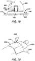
- FIG. 19depicts a partial cross-sectional view of the charging peg system of FIG. 18 , including a coupled medical device;
- FIG. 20depicts an exemplary medical device powered by supercapacitors, with a charging pad draped over a patient.
- FIG. 1shows components of an exemplary medical device ( 10 ) in diagrammatic block form.
- medical device ( 10 )comprises a control module ( 12 ), a power source ( 14 ), and an end effector ( 16 ).
- power sources ( 14 )may include NiMH batteries, Li-ion batteries (e.g., prismatic cell type lithium ion batteries, etc.), Ni-Cad batteries, or any other type of power source as may be apparent to one of ordinary skill in the art in light of the teachings herein.
- Control module ( 12 )may comprise a microprocessor, an application specific integrated circuit (ASIC), memory, a printed circuit board (PCB), a storage device (such as a solid state drive or hard disk), firmware, software, or any other suitable control module components as will be apparent to one of ordinary skill in the art in light of the teachings herein.
- Control module ( 12 ) and power source ( 14 )are coupled by an electrical connection ( 22 ), such as a cable and/or traces in a circuit board, etc., to transfer power from power source ( 14 ) to control module ( 12 ).
- power source ( 14 )may be selectively coupled to control module ( 12 ).
- control module ( 12 )may be removed for servicing, testing, replacement, or any other purpose as will be apparent to one of ordinary skill in the art in view of the teachings herein.
- End effector ( 16 )is coupled to control module ( 12 ) by another electrical connection ( 22 ).
- End effector ( 16 )is configured to perform a desired function of medical device ( 10 ).
- a desired functionmay include cauterizing tissue, ablating tissue, severing tissue, ultrasonically vibrating, stapling tissue, or any other desired task for medical device ( 10 ).
- End effector ( 16 )may thus include an active feature such as an ultrasonic blade, a pair of clamping jaws, a sharp knife, a staple driving assembly, a monopolar RF electrode, a pair of bipolar RF electrodes, a thermal heating element, and/or various other components.
- End effector ( 16 )may also be removable from medical device ( 10 ) for servicing, testing, replacement, or any other purpose as will be apparent to one of ordinary skill in the art in view of the teachings herein.
- end effector ( 16 )is modular such that medical device ( 10 ) may be used with different kinds of end effectors (e.g., as taught in U.S. Provisional Application Ser. No. 61/410,603, etc.).
- Various other configurations of end effector ( 16 )may be provided for a variety of different functions depending upon the purpose of medical device ( 10 ) as will be apparent to those of ordinary skill in the art in view of the teachings herein.
- other types of components of a medical device ( 10 ) that may receive power from power source ( 14 )will be apparent to those of ordinary skill in the art in view of the teachings herein.
- Medical device ( 10 ) of the present exampleincludes a trigger ( 18 ) and a sensor ( 20 ), though it should be understood that such components are merely optional.
- Trigger ( 18 )is coupled to control module ( 12 ) and power source ( 14 ) by electrical connection ( 22 ).
- Trigger ( 18 )may be configured to selectively provide power from power source ( 14 ) to end effector ( 16 ) (and/or to some other component of medical device ( 10 )) to activate medical device ( 10 ) when performing a procedure.
- Sensor ( 20 )is also coupled to control module ( 12 ) by an electrical connection ( 22 ) and may be configured to provide a variety of information to control module ( 12 ) during a procedure.
- such configurationsmay include sensing a temperature at end effector ( 16 ) or determining the oscillation rate of end effector ( 16 ).
- Data from sensor ( 20 )may be processed by control module ( 12 ) to effect the delivery of power to end effector ( 16 ) (e.g., in a feedback loop, etc.).
- control module ( 12 )may process data from sensor ( 20 ) to effect the delivery of power to end effector ( 16 ) (e.g., in a feedback loop, etc.).
- Various other configurations of sensor ( 20 )may be provided depending upon the purpose of medical device ( 10 ) as will be apparent to those of ordinary skill in the art in view of the teachings herein.
- medical device ( 10 )may have more than one sensor ( 20 ), or sensor ( 20 ) may simply be omitted if desired.
- FIG. 2depicts a merely exemplary form that medical device ( 10 ) may take.
- a medical device ( 100 )comprising a power source ( 110 ), a control module ( 120 ), a housing ( 130 ), end effector ( 140 ), and an electrical connection ( 150 ).
- power source ( 110 )is located internally within housing ( 130 ) of medical device ( 100 ).
- power source ( 110 )may only partially extend into housing ( 130 ) and may be selectively attachable to a portion of housing ( 130 ).
- a portion of housing ( 130 )may extend into power source ( 110 ) and power source ( 110 ) may be selectively attachable to the portion of housing ( 130 ).
- Power source ( 110 )may also be configured to detach from medical device ( 100 ) and decouple from control module ( 120 ) or electrical connection ( 150 ). As a result, power source ( 110 ) may be completely separated from medical device ( 100 ) in some versions. As is readily apparent, this may allow the power source ( 110 ) to be removed to be recharged or reclaimed for resterilization and reuse, such as in accordance with various teachings herein. After recharging, or after an initial charge, power source ( 110 ) may be inserted or reinserted into medical device ( 100 ) and secured to housing ( 130 ) or internally within housing ( 130 ). Of course, medical device ( 100 ) may also allow power source ( 110 ) to be charged and/or recharged while power source ( 110 ) is still in or otherwise coupled relative to housing ( 130 ).
- control module ( 120 )may be removed for servicing, testing, replacement, or any other purpose as will be apparent to one of ordinary skill in the art in view of the teachings herein.
- end effector ( 140 )may also be removable from medical device ( 100 ) for servicing, testing, replacement, or any other purpose as will be apparent to one of ordinary skill in the art in view of the teachings herein. While certain configurations of an exemplary medical device ( 100 ) have been described, various other ways in which medical device ( 100 ) may be configured will be apparent to those of ordinary skill in the art in view of the teachings herein.
- medical devices10 , 100 and/or any other medical device referred to herein may be constructed in accordance with at least some of the teachings of U.S. Pat. Nos. 6,500,176; 7,416,101; 7,738,971; U.S. Pub. No. 2006/0079874, now abandoned; U.S. Pub. No. 2007/0191713, now abandoned; U.S. Pub. No. 2007/0282333, now abandoned; U.S. Pub. No. 2008/0200940, now abandoned; U.S. Pub. No. 2009/0209990, issued as U.S. Pat. No. 8,657,174 on Feb. 25, 2014; U.S. Pub. No. 2010/0069940, issued as U.S. Pat. No. 9,023,071 on May 5, 2015; and/or U.S. Provisional Application Ser. No. 61/410,603.
- FIG. 3shows an exemplary medical device ( 200 ) that includes an integral power source ( 218 ) and that also relies on external power.
- Medical device ( 200 ) of this exampleincludes a handpiece ( 210 ), an end effector ( 212 ) disposed at the distal end of a shaft ( 214 ), and a trigger ( 216 ).
- Integral power source ( 218 )is included within the handpiece ( 210 ) and selectively activates end effector ( 212 ) in accordance with actuations of trigger ( 216 ).
- end effector ( 212 )may comprise a harmonic blade, a pair of clamping jaws, and/or one or more electrosurgical elements.
- medical device ( 200 )may be constructed and operable in accordance with medical device ( 10 , 100 ) and/or in accordance with at least some of the teachings of any of the references cited herein.
- Various other kinds of devices to which the teachings of medical device ( 200 ) may be appliedwill be apparent to those of ordinary skill in the art in view of the teachings herein.
- integral power source ( 218 )includes a single battery.
- integral power source ( 218 ) in this exampleprovides enough power in a single charge to activate end effector ( 212 ) one or more times during a normal use of medical device ( 200 ) in a medical procedure.
- integral power source ( 218 ) in this exampledoes not necessarily provide enough power to activate end effector ( 212 ) as many times as needed during a normal use of medical device ( 200 ) in a medical procedure without providing at least some degree of recharging of integral power source ( 218 ).
- a relatively thin charging wire ( 230 )is coupled with handpiece ( 210 ) at coupling ( 220 ).
- Charging wire ( 230 )is also coupled with an adapter ( 232 ), which is further coupled with a conventional power cable ( 234 ).
- Power cable ( 234 )is plugged into a conventional wall outlet ( 236 ), though it should be understood that charging wire ( 230 ), adapter ( 232 ), and/or power cable ( 234 ) may alternatively be coupled with a piece of capital equipment and/or some other component.
- Charging wire ( 230 )is operable to deliver enough power to integral power source ( 218 ) to sufficiently charge integral power source ( 218 ) during a normal use of medical device ( 200 ) in a medical procedure.
- charging wire ( 230 )does not have sufficient thickness to provide all power needed to activate end effector ( 212 ) during normal use of medical device ( 200 ) in a medical procedure.
- charging wire ( 230 ) and integral power source ( 218 )work in tandem—with integral power source ( 218 ) being the primary power source for end effector ( 212 ) and with charging wire ( 230 ) being used to recharge integral power source ( 218 ) (e.g., between selective activations of end effector ( 212 ), etc.).
- Charging wire ( 230 ) of the present exampleis also substantially thinner than conventional power cable ( 234 ). It should be understood that this may provide greater mobility for medical device ( 200 ) due to reduced weight pulling on handpiece ( 210 ), particularly if adapter ( 232 ) and cable ( 234 ) rest on the floor. As is also shown in FIG. 3 , power cable ( 234 ) and adapter ( 232 ) are located in a non-sterile field ( 240 ) while charging wire ( 230 ) and the rest of medical device ( 200 ) are located in a sterile field ( 250 ) in the present example.
- thismay facilitate re-use of power cable ( 234 ) and adapter ( 232 ) in various medical procedures with various medical devices ( 200 ), without having to re-sterilize power cable ( 234 ) and adapter ( 232 ) for each re-use.
- itmay still be desirable to sterilize charging wire ( 230 ) and the rest of medical device ( 200 ) before medical device ( 200 ) is used in a medical procedure, regardless of whether charging wire ( 230 ) and/or other parts of medical device ( 200 ) are re-used in subsequent medical procedures.
- integral power source ( 218 )may be provided with a partial charge in the kit.
- integral power source ( 218 )may help reduce the overall cost and weight of medical device ( 200 ).
- using a larger integral power source ( 218 ) that is capable of activating end effector ( 212 ) enough times during normal use of medical device ( 200 ) without such a power source ( 218 ) having to be rechargedmight result in a more expensive and/or heavier medical device ( 200 ).
- integral power source ( 218 )may comprise more than one battery or may even comprise some kind of power source other than a battery.
- integral power source ( 218 )may be configured to hold enough charge sufficient to activate end effector ( 212 ) enough times during normal use of medical device ( 200 ) without such a power source ( 218 ) having to be recharged.
- FIG. 4shows coupling ( 220 ) of the present example in greater detail.
- coupling ( 220 )a first magnet ( 222 ) integral with handpiece ( 210 ) and a second magnet ( 224 ) integral with a strain relief ( 226 ) on wire ( 230 ).
- magnets ( 222 , 224 )provide relatively quick and easy coupling/decoupling of wire ( 230 ) and handpiece ( 210 ).
- handpiece ( 210 ) and wire ( 230 )also present complementary contacts, prongs and sockets, and/or other features to provide electrical communication from wire ( 230 ) to integral power source ( 218 ).
- Magnets ( 222 , 224 )may be located adjacent to such electrical communication features.
- Handpiece ( 210 ) and/or wire ( 230 )may also include one or more bosses or other guide features configured to facilitate proper coupling of wire ( 230 ) with handpiece ( 210 ).
- magnets ( 222 , 224 )are merely optional, and that a variety of other types of features may be used, including but not limited to latches, clamps, clips, friction fittings, etc.
- a surgeonmay wish to decouple wire ( 230 ) from handpiece ( 210 ) to provide greater mobility or positioning of medical device ( 200 ).
- wire ( 230 )may be readily re-coupled with handpiece ( 210 ) at coupling ( 220 ), even in the operating room, to provide any additional charge that may be needed for integral power source ( 218 ) after one or more activations of end effector ( 212 ).
- handpiece ( 210 ) or some other component of medical device ( 200 )may include a charge indicator, providing a visual and/or audio indication of the charge state of power source ( 218 ), thereby alerting the surgeon to when power source ( 218 ) needs to be recharged.
- Still other suitable components, features, configurations, and operabilities of medical device ( 200 )will be apparent to those of ordinary skill in the art in view of the teachings herein.
- FIGS. 5-9show an exemplary kit ( 300 ) and its various components, including a medical device ( 310 ), batteries ( 320 ), a control module ( 330 ) (e.g., printed circuit board, generator board, etc.), and a reclamation bag ( 340 ), all of which are positioned in respective compartments of packaging ( 350 ).
- Packaging ( 350 ) of the present examplecomprises a sterile blister pack, though it should be understood that packaging ( 350 ) may take any other suitable form.
- packaging ( 350 )is constructed in accordance with the teachings of U.S. patent application Ser. No. 13/151,515, entitled “Sterile Package System for Medical Device,” filed Jun. 2, 2011, published Dec. 6, 2012 as U.S. Pub. No.
- packaging ( 350 )may facilitate sterilization and sealing of medical device ( 310 ) separate from sterilization and sealing of batteries ( 320 ) and control module ( 330 ).
- packaging ( 350 )may be configured to facilitate sterilization and sealing of medical device ( 310 ) separate from sterilization and sealing of batteries ( 320 ) and control module ( 330 ).
- packaging ( 350 )may be configured to facilitate sterilization and sealing of medical device ( 310 ) separate from sterilization and sealing of batteries ( 320 ) and control module ( 330 ).
- packaging ( 350 )may be configured will be apparent to those of ordinary skill in the art in view of the teachings herein.
- Medical device ( 310 ) of the present exampleincludes a handpiece ( 312 ), an end effector ( 314 ) disposed at the distal end of a shaft ( 316 ), and a trigger ( 318 ).
- handpiece ( 312 )includes a first slot ( 360 ) configured to receive battery ( 320 ) and a second slot ( 370 ) configured to receive control module ( 330 ).
- Such slots ( 360 , 370 )may include latching features configured to selectively retain battery ( 320 ) and control module ( 330 ) in handpiece ( 312 ) after insertion.
- Slots ( 360 , 370 )may also include leads sufficient to establish electrical communication with inserted battery ( 320 ) and control module ( 330 ).
- slot ( 360 , 370 )may be configured in accordance with the teachings of U.S. patent application Ser. No. 13/151,512, entitled “Medical Device with Feature for Sterile Acceptance of Non-Sterile Reusable Component,” filed Jun. 2, 2011, published May 10, 2012 as U.S. Pub. No. 2012/0110810, issued as U.S. Pat. No. 9,072,523 on Jul. 7, 2015, the disclosure of which is incorporated by reference herein.
- Other suitable configurations for slots ( 360 , 370 )will be apparent to those of ordinary skill in the art in view of the teachings herein.
- a charged battery ( 320 )is preloaded in handpiece ( 312 ), such that medical device ( 310 ) is immediately ready for use upon removal from packaging ( 350 ). In some such instances, remaining batteries ( 320 ) in packaging ( 350 ) are simply relied on for backup in the event that the preloaded battery ( 320 ) loses sufficient charge.
- handpiece ( 312 ) of the present examplealso includes a battery life indicator ( 362 ), which is operable to indicate how much charge is left in battery ( 320 ).
- battery life indicator ( 362 )is merely optional. If the charge level of a battery ( 320 ) gets too low during a medical procedure, the user may simply eject battery ( 320 ) as described below and use another, fully charged battery ( 320 ) from packaging ( 350 ).
- having several batteries ( 320 ) on hand in packaging ( 350 )may facilitate use of relatively small batteries ( 320 ), which may in turn reduce the overall weight of medical device ( 310 ) during use of medical device ( 310 ) in a medical procedure.
- Extra batteries ( 320 )may continue to be charged in packaging ( 350 ) during the medical procedure.
- end effector ( 314 )may comprise a harmonic blade, a pair of clamping jaws, and/or one or more electrosurgical elements.
- medical device ( 310 )may be constructed and operable in accordance with medical device ( 10 , 100 ) and/or in accordance with at least some of the teachings of any of the references cited herein.
- Various other kinds of devices to which the teachings of medical device ( 310 ) may be appliedwill be apparent to those of ordinary skill in the art in view of the teachings herein.
- kit ( 300 )also includes a power cord ( 322 ) coupled with batteries ( 320 ).
- power cord ( 322 )is coupled with batteries ( 320 ) via a charger ( 324 ) that is integral with packaging ( 350 ) (e.g., disposed within a recess formed by packaging ( 350 ), etc.).
- a charger ( 324 )that is integral with packaging ( 350 ) (e.g., disposed within a recess formed by packaging ( 350 ), etc.).
- power cord ( 322 )is operable to charge batteries ( 320 ).
- kit ( 300 )is shipped and stored with batteries ( 320 ) having only a partial charge, such that batteries ( 320 ) need to be charged before medical device ( 310 ) is used in a medical procedure.
- a usermay initially receive kit ( 300 ) in the form shown in FIG. 5 , which may include a peelable film cover, lid, or other removable feature.
- kit ( 300 )may include a peelable film cover, lid, or other removable feature.
- the usermay place kit ( 300 ) on a mayo stand in the operating room (or place kit ( 300 ) elsewhere), remove the film cover, lid, or other removable feature, and then plug power cord ( 322 ) into wall outlet ( 326 ) as shown in FIG. 6 .
- Charger ( 324 ), packaging ( 350 ), and/or batteries ( 320 )may include visual and/or audio indicators configured to convey the charge state of batteries ( 320 ) to the user.
- batteries ( 320 )are sufficiently charged, the user may then insert battery ( 320 ) and control module ( 330 ) into respective slots ( 360 , 370 ) of handpiece ( 312 ), as shown in FIG. 7 .
- Medical device ( 310 )is then ready to be used in a medical procedure.
- Handpiece ( 312 ) of the present examplealso includes a component ejection feature ( 380 ), which includes a button and a spring-loaded release mechanism. As shown in FIG. 8 , component ejection feature ( 380 ) is operable to eject control module ( 330 ) and battery ( 320 ) from handpiece ( 312 ). In some versions, a single component ejection feature ( 380 ) simultaneously ejects both battery ( 320 ) and control module ( 330 ). In some other versions, separate component ejection features ( 380 ) are provided for independent ejection of battery ( 320 ) and control module ( 330 ).
- reclamation bag ( 340 )may be used to collect used batteries ( 320 ), control module ( 330 ), and/or other components (e.g., charger ( 324 ), etc.).
- Filled reclamation bag ( 340 )may then be sent off to reclaim, salvage, or otherwise further process the components contained therein, with the remainder of kit ( 300 ) being discarded or otherwise disposed of.
- reclamation bag ( 340 )includes a drawstring ( 342 ), though it should be understood that any other suitable type of closure feature may be used.
- control module ( 330 )is not removable from medical device ( 310 ), such that only battery ( 320 ) is removable from medical device ( 310 ). Similarly, in some versions control module ( 330 ) is removable from medical device ( 310 ) and either battery ( 320 ) is non-removable or medical device ( 310 ) receives power from some other source. It should also be understood that charger ( 324 ) or some other feature of kit ( 300 ) may be configured to safely discharge batteries ( 320 ) before batteries ( 320 ) are disposed of or sent off for reclamation/processing in reclamation bag ( 340 ). Still other suitable components, features, configurations, and operabilities of kit ( 300 ) will be apparent to those of ordinary skill in the art in view of the teachings herein.
- the docking station or other charging deviceis not sterile, it may be desirable to prevent such non-sterility from contaminating a sterile medical device when some degree of contact is required between the docking station or other charging device and the medical device in order to charge/recharge the medical device.
- the following examplespresent ways in which a non-sterile charging device may be used to charge a sterile medical device without compromising the sterility of the medical device despite some degree of contact with the medical device. Further examples and variations will be apparent to those of ordinary skill in the art in view of the teachings herein.
- FIGS. 10-12show an exemplary charging station ( 400 ) that includes a base ( 410 ), a film ( 420 ), and a collar ( 430 ).
- Charging station ( 400 )is shown as coupling with a handpiece ( 450 ) of a medical device.
- handpiece ( 450 )includes an integral power source ( 460 ) and a pair of contacts ( 462 ) that are coupled with power source ( 460 ) via wires ( 464 ).
- Power source ( 460 )may comprise one or more batteries and/or various other components.
- Contacts ( 462 )are recessed within handpiece ( 450 ) in this example. In some versions, contacts ( 462 ) define or are provided in respective sockets.
- the medical device having handpiece ( 450 )may be constructed and operable in accordance with medical device ( 10 , 100 ) and/or in accordance with at least some of the teachings of any of the references cited herein.
- Various other types of devices that may include handpiece ( 450 )will be apparent to those of ordinary skill in the art in view of the teachings herein.
- Base ( 410 )includes a power cord ( 412 ) that is configured to plug into a conventional wall outlet or a piece of capital equipment.
- a pair of spike contacts ( 414 )protrude upwardly from base ( 410 ). While spike contacts ( 414 ) have a sharp conical shape in the present example, it should be understood that contacts ( 414 ) may have any other suitable shape.
- Contacts ( 462 ) of handpiece ( 450 )are configured to receive spike contacts ( 414 ) when handpiece is coupled with charging station ( 400 ), such that spike contacts ( 414 ) are operable to charge power source ( 460 ).
- Collar ( 430 )is configured to insertingly receive a lower portion of handpiece ( 450 ) and is configured to provide structural support to handpiece ( 450 ).
- collar ( 430 )has angled sidewalls ( 432 ) providing a tapered configuration, which helps prevent handpiece ( 450 ) and collar ( 430 ) from tipping over.
- contacts ( 414 )are shown protruding upwardly from base ( 410 ), it should be understood that the contacts ( 414 ) could alternatively reside and point downwardly from within handpiece ( 450 ) and make contact with contacts of base ( 410 ).
- Film ( 420 )comprises a sterile sheet of plastic film, and is configured to provide a sterile barrier between the exterior of sterile handpiece ( 450 ) and non-sterile base ( 410 ).
- film ( 420 )is interposed between handpiece ( 450 ) and base ( 410 ).
- collar ( 430 )is also sterile, and is also positioned above film ( 420 ).
- film ( 420 )may optionally be draped over collar ( 430 ), and that film ( 420 ) may deform when handpiece ( 450 ) is inserted in collar ( 430 ), such that film ( 420 ) may serve as a sterile barrier between the sterile exterior of handpiece ( 450 ) and a non-sterile collar ( 430 ).
- film ( 420 ) of the present exampleincludes a pair of openings ( 422 ) associated with spike contacts ( 414 ).
- openings ( 422 )are sized and configured to permit passage of spike contacts ( 414 ) therethrough.
- openings ( 422 )are eliminated, and spike contacts ( 414 ) pierce and poke through film ( 420 ) when handpiece ( 450 ) is pressed onto base ( 410 ) through collar ( 430 ).
- spike contacts ( 414 )are selectively retractable within base ( 410 ).
- spike contacts ( 414 )may be retracted in base ( 410 ) as charging station ( 400 ) is being prepared for use, as shown in FIG. 10 .
- Base ( 410 )may include an actuating mechanism (not shown) that is operable to deploy spike contacts ( 414 ) at an appropriate time.
- Such a mechanismmay employ springs, solenoids, and/or various other types of components to deploy spike contacts ( 414 ).
- base ( 410 )may include a button, switch, slider, or other feature operable to selectively activate such an actuation mechanism.
- base ( 410 )may include a feature that is responsive to placement of collar ( 430 ) and/or handpiece ( 450 ) against base ( 410 ), such that spike contacts ( 414 ) deploy upon placement of collar ( 430 ) and/or handpiece ( 450 ) against base ( 410 ).
- spike contacts ( 414 )are integral features of collar ( 430 ) instead of being integral features of base ( 410 ).
- base ( 410 )may present a pair of contacts that mate with complementary contacts on the underside of collar ( 430 ), through openings ( 422 ) in film ( 420 ). Such contacts on the underside of collar ( 430 ) may be in communication with spike contacts ( 414 ).
- Still other suitable components, features, configurations, and operabilities of charging station ( 400 )will be apparent to those of ordinary skill in the art in view of the teachings herein.
- FIGS. 13A-13Cshow another exemplary charging station ( 500 ) that includes a base ( 510 ) having a recess ( 512 ) and movable retention pins ( 514 ).
- Recess ( 512 )is sized and shaped to receive a lower portion of a handpiece ( 550 ) of a medical device.
- Handpiece ( 550 ) of this exampleincludes an integral power source ( 560 ) and a pair of protruding prongs ( 562 ) that are removably received in sockets ( 564 ) of handpiece ( 550 ).
- sockets ( 564 )may include conductive leaf spring features and/or other features that substantially hold prongs ( 562 ) in sockets ( 564 ) yet release prongs ( 562 ) from sockets ( 564 ) when prongs ( 562 ) are pulled from sockets ( 564 ) with sufficient force.
- Sockets ( 564 )are further coupled with power source ( 560 ) via wires ( 566 ).
- Power source ( 560 )may comprise one or more batteries and/or various other components.
- the medical device having handpiece ( 550 )may be constructed and operable in accordance with medical device ( 10 , 100 ) and/or in accordance with at least some of the teachings of any of the references cited herein. Various other types of devices that may include handpiece ( 550 ) will be apparent to those of ordinary skill in the art in view of the teachings herein.
- Base ( 510 ) of the present exampleincludes a cable (not shown) that is configured to plug into a conventional wall outlet or piece of capital equipment, etc., to deliver a charge to power source ( 560 ) as described in greater detail below.
- Retention pins ( 514 )are configured to move toward a central member ( 516 ) within recess ( 512 ) when prongs ( 562 ) are sufficiently positioned within recess ( 512 ).
- base ( 510 )may include a spring-loaded trip mechanism that is responsive to insertion of prongs ( 562 ) in recess, and such a trip mechanism may cause pins ( 514 ) to move toward central member ( 516 ) as shown in FIG. 13B .
- Such a trip mechanismmay include one or more springs or other resilient members, levers, rockers, cams, etc.
- pins ( 514 )are configured to trap prongs ( 562 ), such as by passing through corresponding openings (not shown) formed in prongs ( 562 ).
- pins ( 514 )are conductive and are configured to deliver a charge to prongs ( 562 ) to thereby charge power source ( 560 ).
- central member ( 516 )is made of a non-conductive material, such that pins ( 514 ) will not short out when they both contact central member ( 516 ).
- the relative lengths of prongs ( 562 ) and recess ( 512 )are selected such that handpiece ( 550 ) does not have to contact base ( 510 ) during charging.
- a gap ( 520 )is presented between base ( 510 ) and handpiece ( 550 ).
- charging station ( 500 )may be non-sterilized and yet still not contaminate sterile handpiece ( 550 ) during charging of power source ( 560 ).
- the interior of recess ( 512 ) and at least a top portion of base ( 510 )are sterilized to further avoid the risk of inadvertently contaminating sterile handpiece ( 550 ).
- prongs ( 562 ) and recess ( 512 )may have any other suitable relative lengths, such that gap ( 520 ) is eliminated and such that part of handpiece ( 550 ) is also disposed in recess ( 512 ) during charging of power source ( 560 ).
- a userinitially positions handpiece ( 550 ) over base ( 510 ) as shown in FIG. 13A .
- the userurges handpiece ( 550 ) downwardly, such that prongs ( 562 ) are disposed in recess, and such that pins ( 514 ) move toward central member ( 516 ) to capture and contact prongs ( 562 ) as shown in FIG. 13B .
- Handpiece ( 550 )remains in this position during charging of power source ( 560 ).
- the charge level of power source ( 560 )may be monitored by a charge indicator on handpiece ( 550 ), on base ( 510 ), or elsewhere.
- base ( 510 )is weighted or otherwise secured to the surface on which it rests in order to provide sufficient resistance to friction encountered by prongs ( 562 ) in sockets ( 564 ), such that base ( 510 ) is not lifted away with handpiece ( 550 ) by prongs ( 562 ).
- handpiece ( 550 )includes a door, cap, or other feature that is operable to close off sockets ( 564 ) when prongs ( 562 ) are pulled free from sockets ( 564 ), thereby effectively sealing off the bottom of handpiece ( 550 ).
- a featuremay be manually operated after handpiece ( 550 ) is pulled away from base ( 510 ).
- a mechanismmay automatically case such a feature to be released to close off sockets ( 564 ) when prongs ( 562 ) are pulled free from sockets ( 564 ).
- Various suitable ways in which such a feature may be providedwill be apparent to those of ordinary skill in the art in view of the teachings herein.
- various other suitable components, features, configurations, and operabilities of charging station ( 500 ) and handpiece ( 550 )will be apparent to those of ordinary skill in the art in view of the teachings herein.
- FIGS. 10-13Crelate to conductive charging, where charging of a power source is provided through direct contact between conductive materials.
- An alternative form of chargingincludes the use of inductive coupling. In particular, energy is exchanged from one inductive coil to another inductive coil via an electromagnetic field, such that the coils together form a transformer, without the coils coming into physical contact with each other.
- inductive chargingmay still present concerns as to sterility, though such concerns may be addressed differently in the context of inductive charging than they would be addressed in the context of conductive charging.
- a non-sterile inductive charging stationmay be used to charge a power source in a sterile medical device without compromising the sterility of the medical device. While several such examples will be discussed in greater detail below, other examples and variations will be apparent to those of ordinary skill in the art in view of the teachings herein.
- FIGS. 14-16depict examples of inductive charging pads that may be used to provide inductive charging and wireless communication of charge state.
- FIG. 14schematically depicts a charging pad ( 600 ) and a medical device ( 650 ).
- Charging pad ( 600 ) of this exampleincludes a primary inductive coil ( 602 ), a control module ( 604 ), a charge indicator ( 606 ), and a power cable ( 608 ).
- Power cable ( 608 )is configured to plug into a conventional wall outlet or piece of capital equipment, etc., and thereby provide power to inductive coil ( 602 ).
- control module ( 604 )is configured to superimpose data on the waveform transmitted by inductive coil ( 602 ), and is further configured to process data received by inductive coil ( 602 ), as will be described in greater detail below.
- control module ( 604 )is configured to provide bi-directional data communication through inductive coil ( 602 ).
- Medical device ( 650 ) of this exampleincludes an integral power source ( 660 ), which includes a secondary inductive coil ( 662 ), a control module ( 664 ), and at least one battery ( 666 ).
- control module ( 664 )may include a variety of components, including but not limited to a printed circuit board, a microprocessor, a memory device, etc.
- Various suitable components, features, and configurations for the various control modules referred to hereinwill be apparent to those of ordinary skill in the art in view of the teachings herein.
- Medical device ( 650 )also includes a charge indicator ( 656 ) in this example, though it should be understood that in other versions either or both of charge indicators ( 606 , 656 ) may be omitted. It should also be understood that medical device ( 650 ) may be constructed and operable in accordance with medical device ( 10 , 100 ) and/or in accordance with at least some of the teachings of any of the references cited herein. For instance, medical device ( 650 ) may include an ultrasonic or electrosurgical end effector (not shown) that is selectively activated by power source ( 660 ). Various other types of forms that medical device ( 650 ) may take will be apparent to those of ordinary skill in the art in view of the teachings herein.
- Control module ( 664 )is operable to monitor the charge level of battery ( 666 ) in real time. Control module ( 664 ) is further operable to drive charge indicator ( 656 ) to indicate the charge level of battery ( 666 ) (e.g., visually and/or audibly) in real time.
- control module ( 664 )is operable to communicate the charge level of battery ( 666 ) back to control module ( 664 ) via coils ( 662 , 602 ).
- control module ( 664 )may superimpose a data carrier on the charging waveform through modulation, allowing such data to be communicated form coil ( 662 ) to coil ( 602 ).
- Control module ( 604 )may receive such data via coil ( 602 ) and react to it in various ways.
- control module ( 604 )may drive charge indicator ( 606 ) to indicate the charge level of battery ( 666 ) (e.g., visually and/or audibly) in real time.
- control module ( 604 )may adjust the charging current provided through coils ( 602 , 662 ), based at least in part on the charge level of battery ( 666 ).
- Control modules ( 604 , 664 )may thus together provide a feedback loop, allowing the charging profile of battery ( 666 ) (e.g., frequency and/or other parameters) to be optimized in real time for whichever battery ( 666 ) is coupled with charging pad ( 600 ).
- the charging profile of battery ( 666 )e.g., frequency and/or other parameters
- the electronics in charging pad ( 600 )may be encapsulated in a potting compound and/or be otherwise encapsulated. Such encapsulation may enable charging pad ( 600 ) to be sterilized using steam and/or other sterilization techniques that might otherwise not be available without damaging charging pad ( 600 ). Of course, charging pad ( 600 ) may be sterilized using a variety of other techniques, including but not limited to electron beam sterilization.
- FIG. 15shows an exemplary charging pad ( 670 ) that includes a power cord ( 672 ) and a relatively large primary coil ( 674 ).
- Primary coil ( 674 )has a diameter spanning across almost the entire length and width of charging pad ( 670 ).
- Primary coil ( 674 )may inductively couple with a similarly sized secondary coil in a medical device (not shown) to provide optimized inductive charging to a battery within the medical device.
- FIG. 16shows an exemplary charging pad ( 680 ) that includes a power cord ( 682 ) and a plurality of smaller primary coils ( 684 ). While primary coils ( 684 ) are relatively small in this example, they are provided in an array that spans across almost the entire length and width of charging pad ( 690 ). Primary coils ( 684 ) may inductively couple with similarly sized and arranged secondary coils in a medical device (not shown) to provide optimized inductive charging to a battery or batteries within the medical device. It should also be understood that charging pad ( 690 ) may accommodate various different medical devices having inductive charging interfaces of various sizes (e.g., such that not all primary coils ( 684 ) are necessarily used every time).
- charging pad ( 600 , 670 , 680 ) and medical device ( 650 )will be apparent to those of ordinary skill in the art in view of the teachings herein. It should also be understood that any charging pad or charging device referred herein may include the communication capabilities discussed above with respect to charging pad ( 600 ), if desired.
- an inductive charging padmay be sterilized using steam, electron beam sterilization, and/or using other sterilization techniques. It should also be understood, however, that an inductive charging pad may still be used, even in an operating room, without the charging pad necessarily being sterilized, and without the non-sterile charging pad compromising the sterility of the medical device that it charges.
- an inductive charging pad ( 800 )may be placed on a mayo stand ( 802 ) (or elsewhere) in an operating room, and a sterile drape ( 804 ) may be placed over charging pad ( 800 ) to act as a sterile barrier.
- sterile battery packsthat are capable of being inductively charged may simply be placed directly on sterile drape ( 804 ) over charging pad ( 800 ).
- battery packsmay have integral inductive charging coils that establish communication with one or more complementary coils in charging pad ( 800 ).
- Such battery packsmay thus be charged by charging pad ( 800 ) through sterile drape ( 804 ), and sterile drape ( 804 ) may help maintain the sterility of the battery packs by preventing contamination from non-sterile charging pad ( 800 ).
- Sterile drape ( 804 )may comprise any suitable material and construction, including but not limited to a plastic film, a suitable fabric, etc.
- FIGS. 18-19depict another exemplary use of a sterile drape and inductive charging device.
- FIGS. 18-19show an inductive charging device ( 900 ) on a mayo stand ( 930 ), with a sterile drape ( 940 ) laid over inductive charging device ( 900 ).
- Inductive charging device ( 900 ) of this exampleincludes a cable ( 902 ) that is configured to plug into a conventional wall outlet ( 904 ), a base portion ( 906 ), an upright peg portion ( 908 ), and a primary coil ( 910 ).
- Primary coil ( 910 )is shown in FIG. 19 as being located within upright peg portion ( 908 ), though it should be understood that primary coil ( 910 ) may be located elsewhere. For instance, in some other versions, primary coil ( 910 ) is located in base portion ( 906 ) (e.g., coaxial with upright peg portion ( 908 ), etc.).
- Charging device ( 900 ) of this exampleis configured for use with a medical device having a handpiece ( 950 ) as shown in FIG. 19 .
- handpiece ( 950 )includes a secondary coil ( 952 ), which is in communication with an integral power source ( 954 ) in handpiece ( 950 ).
- the bottom of handpiece ( 950 )defines a recess ( 956 ) that is configured to receive upright peg portion ( 908 ) of charging device ( 900 ). Upright peg portion ( 908 ) and recess ( 956 ) thus cooperate to assist in properly positioning coils ( 910 , 952 ) relative to each other.
- Upright peg portion ( 908 )also provides some degree of structural support to handpiece ( 950 ) (e.g., reducing the likelihood of handpiece ( 950 ) tipping over, etc.).
- coils ( 910 , 952 )are properly positioned within sufficient proximity of each other, coils ( 910 , 952 ) inductively couple, forming a transformer and charging power source ( 954 ).
- Sterile drape ( 940 )conforms to the interface between handpiece ( 950 ) and charging device ( 900 ), this maintaining the sterile barrier between these components while also permitting inductive charging to occur therethrough.
- charging device ( 950 )may be used in an operating room without being sterile and without compromising the sterility of handpiece ( 950 ) or other items in the operating room.
- power source ( 954 )may be charged by charging device ( 900 ) through sterile drape ( 940 ), and sterile drape ( 940 ) may help maintain the sterility of handpiece ( 950 ) by preventing contamination from non-sterile charging device ( 900 ).
- the medical device having handpiece ( 950 )may be constructed and operable in accordance with medical device ( 10 , 100 ) and/or in accordance with at least some of the teachings of any of the references cited herein.
- Various other types of devices that may include handpiece ( 950 )will be apparent to those of ordinary skill in the art in view of the teachings herein.
- various other suitable forms that charging device ( 900 ) may takewill be apparent to those of ordinary skill in the art in view of the teachings herein.
- FIG. 20shows a medical device ( 1000 ) having an integral power source ( 1010 ) that comprises one or more supercapacitors, also known as electric double-layer capacitors (EDLCs).
- EDLCselectric double-layer capacitors
- Medical devicemay otherwise be constructed and operable in accordance with medical device ( 10 , 100 ) and/or in accordance with at least some of the teachings of any of the references cited herein.
- one or more supercapacitors of power source ( 1010 )may provide sufficient power to perform one or more operational acts with medical device ( 1000 ) (e.g., one or more transections with an end effector of medical device ( 1000 ), etc.).
- the power provided by supercapacitors of power source ( 1010 )may be more in the form of short bursts as compared to the power delivery that might be expected from conventional batteries. It therefore might be warranted in some instances to provide relatively immediate recharging of power source ( 1010 ).
- FIG. 20also shows a charging pad ( 1020 ) draped directly over the torso of a patient ( 1030 ).
- Charging pad ( 1020 )includes a power cable ( 1022 ) that is configured to plug into a conventional wall outlet or piece of capital equipment, etc.
- Charging pad ( 1020 )is further configured to charge power source ( 1010 ) through inductive coupling or otherwise. Due to the nature of supercapacitors, the charging of power source ( 1010 ) may be much faster than the charge time that might otherwise be expected with conventional rechargeable batteries. Thus, in the present example, a surgeon may repeatedly place medical device ( 1000 ) on or at least directly over charging pad ( 1020 ) as many times as needed to keep power source ( 1010 ) sufficiently charged during a medical procedure.
- Charging pad ( 1020 )may be sterilized before use; or may have a sterile drape placed over it (and under it) to avoid contaminating medical device ( 1000 ) (and patient ( 1030 )). It should also be understood that charging pad ( 1020 ) may be placed anywhere, and need not necessarily be draped over patient ( 1030 ). It should also be understood that medical device ( 1000 ) may include a magnet or other feature that helps keep medical device ( 1000 ) upright (e.g., to avoid tipping over, etc.) when medical device ( 1000 ) is plaled on charging pad ( 1020 ). Various other suitable ways in which supercapacitors may be incorporated into a medical device will be apparent to those of ordinary skill in the art in view of the teachings herein. It should also be understood that, in any example mentioned herein that includes one or more batteries, such batteries may be replaced or supplemented with a capacitor, supercapacitor, and/or other type of power source.
- Embodiments of the present inventionhave application in conventional endoscopic and open surgical instrumentation as well as application in robotic-assisted surgery.
- Embodiments of the devices disclosed hereincan be designed to be disposed of after a single use, or they can be designed to be used multiple times. Embodiments may, in either or both cases, be reconditioned for reuse after at least one use. Reconditioning may include any combination of the steps of disassembly of the device, followed by cleaning or replacement of particular pieces, and subsequent reassembly. In particular, embodiments of the device may be disassembled, and any number of the particular pieces or parts of the device may be selectively replaced or removed in any combination. Upon cleaning and/or replacement of particular parts, embodiments of the device may be reassembled for subsequent use either at a reconditioning facility, or by a surgical team immediately prior to a surgical procedure.
- reconditioning of a devicemay utilize a variety of techniques for disassembly, cleaning/replacement, and reassembly. Use of such techniques, and the resulting reconditioned device, are all within the scope of the present application.
- a new or used instrumentmay be obtained and if necessary cleaned.
- the instrumentmay then be sterilized.
- the instrumentis placed in a closed and sealed container, such as a plastic or TYVEK bag.
- the container and instrumentmay then be placed in a field of radiation that can penetrate the container, such as gamma radiation, x-rays, or high-energy electrons.
- the radiationmay kill bacteria on the instrument and in the container.
- the sterilized instrumentmay then be stored in the sterile container.
- the sealed containermay keep the instrument sterile until it is opened in a medical facility.
- a devicemay also be sterilized using any other technique known in the art, including but not limited to beta or gamma radiation, ethylene oxide, or steam.
Landscapes
- Health & Medical Sciences (AREA)
- Engineering & Computer Science (AREA)
- Surgery (AREA)
- Life Sciences & Earth Sciences (AREA)
- Public Health (AREA)
- Biomedical Technology (AREA)
- General Health & Medical Sciences (AREA)
- Medical Informatics (AREA)
- Animal Behavior & Ethology (AREA)
- Veterinary Medicine (AREA)
- Nuclear Medicine, Radiotherapy & Molecular Imaging (AREA)
- Molecular Biology (AREA)
- Heart & Thoracic Surgery (AREA)
- Otolaryngology (AREA)
- Physics & Mathematics (AREA)
- Plasma & Fusion (AREA)
- Power Engineering (AREA)
- Epidemiology (AREA)
- Primary Health Care (AREA)
- Chemical Kinetics & Catalysis (AREA)
- Manufacturing & Machinery (AREA)
- Chemical & Material Sciences (AREA)
- Electrochemistry (AREA)
- General Chemical & Material Sciences (AREA)
- Pathology (AREA)
- Mechanical Engineering (AREA)
- Dentistry (AREA)
- Oral & Maxillofacial Surgery (AREA)
- Computer Networks & Wireless Communication (AREA)
- Business, Economics & Management (AREA)
- Radiology & Medical Imaging (AREA)
- General Business, Economics & Management (AREA)
- Urology & Nephrology (AREA)
- Ophthalmology & Optometry (AREA)
- Human Computer Interaction (AREA)
- Robotics (AREA)
- Charge And Discharge Circuits For Batteries Or The Like (AREA)
- Battery Mounting, Suspending (AREA)
Abstract
Description
Claims (18)
Priority Applications (2)
| Application Number | Priority Date | Filing Date | Title |
|---|---|---|---|
| US15/212,423US10660695B2 (en) | 2010-11-05 | 2016-07-18 | Sterile medical instrument charging device |
| US16/779,748US11744635B2 (en) | 2010-11-05 | 2020-02-03 | Sterile medical instrument charging device |
Applications Claiming Priority (4)
| Application Number | Priority Date | Filing Date | Title |
|---|---|---|---|
| US41060310P | 2010-11-05 | 2010-11-05 | |
| US201161487846P | 2011-05-19 | 2011-05-19 | |
| US13/151,503US9597143B2 (en) | 2010-11-05 | 2011-06-02 | Sterile medical instrument charging device |
| US15/212,423US10660695B2 (en) | 2010-11-05 | 2016-07-18 | Sterile medical instrument charging device |
Related Parent Applications (1)
| Application Number | Title | Priority Date | Filing Date |
|---|---|---|---|
| US13/151,503ContinuationUS9597143B2 (en) | 2010-11-05 | 2011-06-02 | Sterile medical instrument charging device |
Related Child Applications (1)
| Application Number | Title | Priority Date | Filing Date |
|---|---|---|---|
| US16/779,748ContinuationUS11744635B2 (en) | 2010-11-05 | 2020-02-03 | Sterile medical instrument charging device |
Publications (2)
| Publication Number | Publication Date |
|---|---|
| US20160329614A1 US20160329614A1 (en) | 2016-11-10 |
| US10660695B2true US10660695B2 (en) | 2020-05-26 |
Family
ID=67148321
Family Applications (2)
| Application Number | Title | Priority Date | Filing Date |
|---|---|---|---|
| US15/212,423Active2033-04-13US10660695B2 (en) | 2010-11-05 | 2016-07-18 | Sterile medical instrument charging device |
| US16/779,748Active2032-04-05US11744635B2 (en) | 2010-11-05 | 2020-02-03 | Sterile medical instrument charging device |
Family Applications After (1)
| Application Number | Title | Priority Date | Filing Date |
|---|---|---|---|
| US16/779,748Active2032-04-05US11744635B2 (en) | 2010-11-05 | 2020-02-03 | Sterile medical instrument charging device |
Country Status (1)
| Country | Link |
|---|---|
| US (2) | US10660695B2 (en) |
Cited By (4)
| Publication number | Priority date | Publication date | Assignee | Title |
|---|---|---|---|---|
| US20200015922A1 (en)* | 2018-07-12 | 2020-01-16 | Davol Inc. | Surgical instrument with fastener preload lock-out |
| US12029416B2 (en) | 2019-04-17 | 2024-07-09 | Davol Inc. | Surgical instrument with fastener preload lock-out |
| USD1054980S1 (en) | 2022-07-22 | 2024-12-24 | Covidien Lp | Medical charging cabinet |
| US12218459B2 (en) | 2022-06-30 | 2025-02-04 | Cilag Gmbh International | Surgical instrument with removable cable and associated couplings |
Families Citing this family (19)
| Publication number | Priority date | Publication date | Assignee | Title |
|---|---|---|---|---|
| US10959769B2 (en) | 2010-11-05 | 2021-03-30 | Ethicon Llc | Surgical instrument with slip ring assembly to power ultrasonic transducer |
| US10660695B2 (en) | 2010-11-05 | 2020-05-26 | Ethicon Llc | Sterile medical instrument charging device |
| US9510895B2 (en) | 2010-11-05 | 2016-12-06 | Ethicon Endo-Surgery, Llc | Surgical instrument with modular shaft and end effector |
| US9782215B2 (en) | 2010-11-05 | 2017-10-10 | Ethicon Endo-Surgery, Llc | Surgical instrument with ultrasonic transducer having integral switches |
| US20120116265A1 (en) | 2010-11-05 | 2012-05-10 | Houser Kevin L | Surgical instrument with charging devices |
| US10881448B2 (en) | 2010-11-05 | 2021-01-05 | Ethicon Llc | Cam driven coupling between ultrasonic transducer and waveguide in surgical instrument |
| US20120116381A1 (en) | 2010-11-05 | 2012-05-10 | Houser Kevin L | Surgical instrument with charging station and wireless communication |
| US9782214B2 (en) | 2010-11-05 | 2017-10-10 | Ethicon Llc | Surgical instrument with sensor and powered control |
| US10164466B2 (en)* | 2014-04-17 | 2018-12-25 | Covidien Lp | Non-contact surgical adapter electrical interface |
| JP6475139B2 (en)* | 2015-10-02 | 2019-02-27 | タイコエレクトロニクスジャパン合同会社 | Battery connecting device and battery connecting device assembly |
| AU2018342093B2 (en) | 2017-09-26 | 2023-09-07 | Stryker Corporation | System and method for wirelessly charging a medical device battery |
| US11622829B2 (en)* | 2018-04-12 | 2023-04-11 | Mizuho Osi | Medical table and surgical drape for use in surgical procedures |
| CA3124135A1 (en) | 2019-01-09 | 2020-07-16 | Conmed Corporation | Sterile battery charging |
| MX2022003641A (en)* | 2019-09-25 | 2022-07-12 | Janssen Pharmaceuticals Inc | Drug delivery device incorporating electrical system contamination protection, power source management, power source monitoring, and/or power source operation. |
| GB2595720A (en)* | 2020-06-05 | 2021-12-08 | Creo Medical Ltd | Electrosurgical apparatus |
| CN112971892A (en)* | 2021-01-18 | 2021-06-18 | 常州安康医疗器械有限公司 | Electric endoscope anastomat with electric quantity display function |
| US12369524B2 (en) | 2021-12-09 | 2025-07-29 | Honda Motor Co., Ltd. | Battery system, power equipment apparatus having the same, and electric lawnmower |
| EP4297233A1 (en)* | 2022-06-23 | 2023-12-27 | Braun GmbH | Power supply device, kit, and methods of manufacturing and using a power supply device |
| US20240000476A1 (en)* | 2022-06-30 | 2024-01-04 | Cilag Gmbh International | Surgical system and methods of assembly and disassembly of surgical instrument |
Citations (404)
| Publication number | Priority date | Publication date | Assignee | Title |
|---|---|---|---|---|
| US1754806A (en) | 1929-09-05 | 1930-04-15 | Holland N Stevenson | Surgical instrument |
| US3297192A (en) | 1965-04-16 | 1967-01-10 | Rexall Drug Chemical | Hinged cap |
| US3419198A (en) | 1965-09-20 | 1968-12-31 | Pettersen Gunnar Nimrod | Covering cap with closable opening for bottle or other container |
| US3619671A (en) | 1969-12-29 | 1971-11-09 | Branson Instr | Transducer for ultrasonic machine tool |
| US4034762A (en) | 1975-08-04 | 1977-07-12 | Electro Medical Systems, Inc. | Vas cautery apparatus |
| US4057220A (en) | 1976-06-10 | 1977-11-08 | Kudlacek Donald S | Ratchet type operator for cable winches and the like |
| JPS5410110B2 (en) | 1974-03-20 | 1979-05-01 | ||
| US4535773A (en) | 1982-03-26 | 1985-08-20 | Inbae Yoon | Safety puncturing instrument and method |
| US4641076A (en) | 1985-01-23 | 1987-02-03 | Hall Surgical-Division Of Zimmer, Inc. | Method and apparatus for sterilizing and charging batteries |
| US4641077A (en) | 1985-01-23 | 1987-02-03 | Hall Surgical-Divison Of Zimmer, Inc. | Method and apparatus for providing sterile charged batteries |
| US4662068A (en) | 1985-11-14 | 1987-05-05 | Eli Polonsky | Suture fusing and cutting apparatus |
| US4666037A (en) | 1986-02-24 | 1987-05-19 | Bernard Weissman | Dental model carrier |
| US4685459A (en) | 1985-03-27 | 1987-08-11 | Fischer Met Gmbh | Device for bipolar high-frequency coagulation of biological tissue |
| US4717050A (en) | 1986-05-19 | 1988-01-05 | Sunbeam Plastics Corporation | Multiple orifice dispensing closure |
| US4717018A (en) | 1984-06-28 | 1988-01-05 | Boehringer Mannheim Gmbh | Container for longitudinally extending diagnostic test strips |
| US4721097A (en) | 1986-10-31 | 1988-01-26 | Circon Corporation | Endoscope sheaths and method and apparatus for installation and removal |
| US4768969A (en) | 1986-03-10 | 1988-09-06 | C. R. Bard, Inc. | Electrical connector |
| US4800878A (en) | 1987-08-26 | 1989-01-31 | Becton, Dickinson And Company | Electrosurgical knife with visual alarm |
| US4844259A (en) | 1987-12-22 | 1989-07-04 | Osteotech, Inc. | Medical and surgical procedure pack |
| JPH01268370A (en) | 1988-04-20 | 1989-10-26 | Matsushita Electric Ind Co Ltd | television receiver |
| US4878493A (en) | 1983-10-28 | 1989-11-07 | Ninetronix Venture I | Hand-held diathermy apparatus |
| US5071417A (en) | 1990-06-15 | 1991-12-10 | Rare Earth Medical Lasers, Inc. | Laser fusion of biological materials |
| US5107155A (en) | 1990-11-16 | 1992-04-21 | Tokyo Parts Industrial Co., Ltd. | Vibrator motor for wireless silent alerting device |
| US5144771A (en) | 1990-02-06 | 1992-09-08 | Brother Kogyo Kabushiki Kaisha | Liquid supply system of an ultrasonic machine |
| US5169733A (en) | 1991-07-08 | 1992-12-08 | Motorola, Inc. | Shock absorbing battery cell interconnect |
| US5176677A (en) | 1989-11-17 | 1993-01-05 | Sonokinetics Group | Endoscopic ultrasonic rotary electro-cauterizing aspirator |
| US5246109A (en) | 1992-05-22 | 1993-09-21 | Biomedical Sensors, Ltd. | Package for an active medical device |
| US5273177A (en) | 1992-07-20 | 1993-12-28 | Campbell Phillip J | Press-to-open dispensing closure |
| US5277694A (en) | 1991-02-13 | 1994-01-11 | Implex Gmbh | Electromechanical transducer for implantable hearing aids |
| US5308358A (en) | 1992-08-25 | 1994-05-03 | Bond Albert L | Rigid-shaft surgical instruments that can be disassembled for improved cleaning |
| US5322055A (en) | 1993-01-27 | 1994-06-21 | Ultracision, Inc. | Clamp coagulator/cutting system for ultrasonic surgical instruments |
| US5339799A (en) | 1991-04-23 | 1994-08-23 | Olympus Optical Co., Ltd. | Medical system for reproducing a state of contact of the treatment section in the operation unit |
| US5358508A (en) | 1993-09-15 | 1994-10-25 | Eric Cobb | Laparoscopic device |
| US5361902A (en) | 1992-06-05 | 1994-11-08 | Leonard Bloom | Surgical blade dispenser and disposal system for use during an operating procedure and method thereof |
| US5429229A (en) | 1991-08-02 | 1995-07-04 | Minnesota Mining And Manufacturing Company | Packaged dental article |
| US5449370A (en) | 1993-05-12 | 1995-09-12 | Ethicon, Inc. | Blunt tipped ultrasonic trocar |
| US5452391A (en) | 1994-06-22 | 1995-09-19 | Xintec Corporation | Reusable optical fiber connector adapter with optical barrier |
| US5454378A (en) | 1993-02-11 | 1995-10-03 | Symbiosis Corporation | Biopsy forceps having a detachable proximal handle and distal jaws |
| US5501607A (en) | 1993-05-13 | 1996-03-26 | Yazaki Corporation | Waterproof structure for charging connector |
| US5507297A (en) | 1991-04-04 | 1996-04-16 | Symbiosis Corporation | Endoscopic instruments having detachable proximal handle and distal portions |
| US5561881A (en) | 1994-03-22 | 1996-10-08 | U.S. Philips Corporation | Electric toothbrush |
| US5578052A (en) | 1992-10-27 | 1996-11-26 | Koros; Tibor | Insulated laparoscopic grasper with removable shaft |
| US5580258A (en) | 1993-06-14 | 1996-12-03 | Sumitomo Wiring Systems, Ltd. | Vehicle charging connector and a receptacle enclosing the connector |
| US5582617A (en) | 1993-07-21 | 1996-12-10 | Charles H. Klieman | Surgical instrument for endoscopic and general surgery |
| US5590778A (en) | 1995-06-06 | 1997-01-07 | Baxter International Inc. | Double-sterile package for medical apparatus and method of making |
| US5592065A (en) | 1995-11-06 | 1997-01-07 | Motorola, Inc. | Battery charger having battery temperature measurement probe |
| US5597371A (en) | 1994-07-22 | 1997-01-28 | Nissan Motor Co., Ltd. | Engine torque controller |
| US5599350A (en) | 1995-04-03 | 1997-02-04 | Ethicon Endo-Surgery, Inc. | Electrosurgical clamping device with coagulation feedback |
| US5630420A (en) | 1995-09-29 | 1997-05-20 | Ethicon Endo-Surgery, Inc. | Ultrasonic instrument for surgical applications |
| US5630456A (en) | 1996-05-08 | 1997-05-20 | Hugo; Marie J. R. | Window blind cord winding apparatus |
| WO1997024072A1 (en) | 1995-12-29 | 1997-07-10 | Riza Erol D | Laparoscopic surgical instrument with adjustable grip |
| US5690222A (en) | 1995-04-07 | 1997-11-25 | Linvatec Corporation | Package retainer for surgical screw |
| US5707369A (en) | 1995-04-24 | 1998-01-13 | Ethicon Endo-Surgery, Inc. | Temperature feedback monitor for hemostatic surgical instrument |
| US5741305A (en) | 1996-05-06 | 1998-04-21 | Physio-Control Corporation | Keyed self-latching battery pack for a portable defibrillator |
| US5776155A (en) | 1996-12-23 | 1998-07-07 | Ethicon Endo-Surgery, Inc. | Methods and devices for attaching and detaching transmission components |
| US5800336A (en) | 1993-07-01 | 1998-09-01 | Symphonix Devices, Inc. | Advanced designs of floating mass transducers |
| US5817128A (en) | 1993-03-10 | 1998-10-06 | Karl Storz Gmbh & Co. | Medical tongs |
| JPH10308907A (en) | 1997-05-09 | 1998-11-17 | Casio Comput Co Ltd | Electronic equipment mounting equipment |
| US5868244A (en) | 1997-12-01 | 1999-02-09 | Ethicon, Inc. | Microbial barrier vented package for sterile medical devices and method of packaging |
| US5873873A (en) | 1997-10-10 | 1999-02-23 | Ethicon Endo-Surgery, Inc. | Ultrasonic clamp coagulator apparatus having improved clamp mechanism |
| EP0897696A1 (en) | 1997-08-14 | 1999-02-24 | United States Surgical Corporation | Ultrasonic dissection and coagulation system |
| US5882310A (en) | 1997-12-01 | 1999-03-16 | Acuson Corporation | Ultrasound transducer connector and multiport imaging system receptacle arrangement |
| US5893835A (en) | 1997-10-10 | 1999-04-13 | Ethicon Endo-Surgery, Inc. | Ultrasonic clamp coagulator apparatus having dual rotational positioning |
| US5935144A (en) | 1998-04-09 | 1999-08-10 | Ethicon Endo-Surgery, Inc. | Double sealed acoustic isolation members for ultrasonic |
| US5938633A (en) | 1997-07-09 | 1999-08-17 | Ethicon Endo-Surgery, Inc. | Ultrasonic surgical devices |
| US5944737A (en) | 1997-10-10 | 1999-08-31 | Ethicon Endo-Surgery, Inc. | Ultrasonic clamp coagulator apparatus having improved waveguide support member |
| US5951575A (en) | 1996-03-01 | 1999-09-14 | Heartport, Inc. | Apparatus and methods for rotationally deploying needles |
| EP0947167A1 (en) | 1998-03-30 | 1999-10-06 | Ethicon Endo-Surgery, Inc. | Methods and apparatus to recognize surgical apparatus |
| US5980510A (en) | 1997-10-10 | 1999-11-09 | Ethicon Endo-Surgery, Inc. | Ultrasonic clamp coagulator apparatus having improved clamp arm pivot mount |
| US5997531A (en) | 1998-01-29 | 1999-12-07 | Cardiodyne, Inc. | User actuated laser energy device and procedure for forming a channel within tissue |
| US6018227A (en) | 1998-06-22 | 2000-01-25 | Stryker Corporation | Battery charger especially useful with sterilizable, rechargeable battery packs |
| US6051010A (en) | 1996-12-23 | 2000-04-18 | Ethicon Endo-Surgery, Inc. | Methods and devices for joining transmission components |
| US6056735A (en) | 1996-04-04 | 2000-05-02 | Olympus Optical Co., Ltd. | Ultrasound treatment system |
| US6063098A (en) | 1996-12-23 | 2000-05-16 | Houser; Kevin | Articulable ultrasonic surgical apparatus |
| US6066151A (en) | 1997-12-24 | 2000-05-23 | Olympus Optical Co., Ltd. | Ultrasonic surgical apparatus |
| US6083223A (en) | 1997-08-28 | 2000-07-04 | Baker; James A. | Methods and apparatus for welding blood vessels |
| US6083191A (en) | 1992-02-07 | 2000-07-04 | Sherwood Services Ag | Ultrasonic surgical apparatus |
| US6099537A (en) | 1996-02-26 | 2000-08-08 | Olympus Optical Co., Ltd. | Medical treatment instrument |
| US6113596A (en) | 1996-12-30 | 2000-09-05 | Enable Medical Corporation | Combination monopolar-bipolar electrosurgical instrument system, instrument and cable |
| US6113593A (en) | 1999-02-01 | 2000-09-05 | Tu; Lily Chen | Ablation apparatus having temperature and force sensing capabilities |
| US6123702A (en) | 1998-09-10 | 2000-09-26 | Scimed Life Systems, Inc. | Systems and methods for controlling power in an electrosurgical probe |
| WO2000065682A1 (en) | 1999-04-26 | 2000-11-02 | Exonix Corporation | Self contained transportable power source maintenance and charge system |
| US6165191A (en) | 1998-05-28 | 2000-12-26 | Olympus Optical Co., Ltd. | Ultrasonic treating tool |
| US6190386B1 (en) | 1999-03-09 | 2001-02-20 | Everest Medical Corporation | Electrosurgical forceps with needle electrodes |
| US6204592B1 (en) | 1999-10-12 | 2001-03-20 | Ben Hur | Ultrasonic nailing and drilling apparatus |
| US6214023B1 (en) | 1999-06-21 | 2001-04-10 | Ethicon Endo-Surgery, Inc. | Ultrasonic surgical instrument with removable clamp arm |
| US6246896B1 (en) | 1998-11-24 | 2001-06-12 | General Electric Company | MRI guided ablation system |
| US6248238B1 (en) | 1996-04-19 | 2001-06-19 | Hospal Industrie | Medical apparatus for the extracorporeal treatment of blood or plasma, and processes for using this apparatus |
| US6287304B1 (en) | 1999-10-15 | 2001-09-11 | Neothermia Corporation | Interstitial cauterization of tissue volumes with electrosurgically deployed electrodes |
| US20010032666A1 (en) | 2000-03-24 | 2001-10-25 | Inegrated Power Solutions Inc. | Integrated capacitor-like battery and associated method |
| US6325811B1 (en) | 1999-10-05 | 2001-12-04 | Ethicon Endo-Surgery, Inc. | Blades with functional balance asymmetries for use with ultrasonic surgical instruments |
| US6339368B1 (en) | 2000-03-31 | 2002-01-15 | Zilog, Inc. | Circuit for automatically driving mechanical device at its resonance frequency |
| US6398755B1 (en) | 1998-10-06 | 2002-06-04 | Scimed Life Systems, Inc. | Driveable catheter system |
| US6409742B1 (en) | 1998-08-19 | 2002-06-25 | Artemis Medical, Inc. | Target tissue localization device and method |
| US20020165577A1 (en) | 2001-05-04 | 2002-11-07 | Ethicon Endo-Surgery, Inc. | Easily detachable ultrasonic clamping device |
| JP2002336265A (en) | 2001-05-16 | 2002-11-26 | Fuji Photo Optical Co Ltd | Body cavity operation device |
| US6500188B2 (en) | 2001-01-29 | 2002-12-31 | Ethicon Endo-Surgery, Inc. | Ultrasonic surgical instrument with finger actuator |
| US6500176B1 (en) | 2000-10-23 | 2002-12-31 | Csaba Truckai | Electrosurgical systems and techniques for sealing tissue |
| US6512667B2 (en) | 2001-02-01 | 2003-01-28 | Luxon Energy Devices Corporation | Supercapacitors and method for fabricating the same |
| US6514267B2 (en) | 2001-03-26 | 2003-02-04 | Iep Pharmaceutical Devices Inc. | Ultrasonic scalpel |
| US6517561B1 (en) | 2000-10-16 | 2003-02-11 | Robert E. Phillips | Motorized specimen cutter |
| US6520185B1 (en) | 1999-03-17 | 2003-02-18 | Ntero Surgical, Inc. | Systems and methods for reducing post-surgical complications |
| WO2003013374A1 (en) | 2001-08-06 | 2003-02-20 | Penn State Research Foundation | Multifunctional tool and method for minimally invasive surgery |
| WO2003020139A2 (en) | 2001-09-03 | 2003-03-13 | Vleugels Michel Petronella Hub | Surgical instrument |
| US6561983B2 (en) | 2001-01-31 | 2003-05-13 | Ethicon Endo-Surgery, Inc. | Attachments of components of ultrasonic blades or waveguides |
| US6562032B1 (en) | 2001-03-26 | 2003-05-13 | Ellman Alan G | Electrosurgical instrument with vibration |
| US20030093103A1 (en) | 2001-08-08 | 2003-05-15 | Don Malackowski | Surgical tool system with components that perform inductive data transfer |
| US20030109802A1 (en) | 2001-12-12 | 2003-06-12 | Laeseke Paul F. | Cauterizing biopsy system |
| US20030114851A1 (en) | 2001-12-13 | 2003-06-19 | Csaba Truckai | Electrosurgical jaws for controlled application of clamping pressure |
| EP1330991A1 (en) | 2002-01-23 | 2003-07-30 | Ethicon Endo-Surgery, Inc. | Electrosurgical instrument with light monitor on effector |
| US20030144680A1 (en) | 2002-01-22 | 2003-07-31 | Sontra Medical, Inc. | Portable ultrasonic scalpel/cautery device |
| US6609414B2 (en) | 2001-07-19 | 2003-08-26 | Mocon, Inc. | Apparatus for conducting leakage tests on sealed packages |
| US6623500B1 (en) | 2000-10-20 | 2003-09-23 | Ethicon Endo-Surgery, Inc. | Ring contact for rotatable connection of switch assembly for use in a surgical system |
| US6622731B2 (en) | 2001-01-11 | 2003-09-23 | Rita Medical Systems, Inc. | Bone-treatment instrument and method |
| US6626901B1 (en) | 1997-03-05 | 2003-09-30 | The Trustees Of Columbia University In The City Of New York | Electrothermal instrument for sealing and joining or cutting tissue |
| US6647281B2 (en) | 2001-04-06 | 2003-11-11 | Scimed Life Systems, Inc. | Expandable diagnostic or therapeutic apparatus and system for introducing the same into the body |
| US6650975B2 (en) | 1999-03-19 | 2003-11-18 | Bryan John Ruffner | Multifunctional mobile appliance |
| US6650091B1 (en) | 2002-05-13 | 2003-11-18 | Luxon Energy Devices Corporation | High current pulse generator |
| US6656177B2 (en) | 2000-10-23 | 2003-12-02 | Csaba Truckai | Electrosurgical systems and techniques for sealing tissue |
| US6658301B2 (en) | 2000-09-13 | 2003-12-02 | Alfred E. Mann Institute For Biomedical Engineering At The University Of Southern California | Method and apparatus for conditioning muscles during sleep |
| US20030225411A1 (en)* | 2002-05-31 | 2003-12-04 | Vidacare Corporation | Apparatus and method to access bone marrow |
| US6666875B1 (en) | 1999-03-05 | 2003-12-23 | Olympus Optical Co., Ltd. | Surgical apparatus permitting recharge of battery-driven surgical instrument in noncontact state |
| US6706038B2 (en) | 2000-04-27 | 2004-03-16 | Medtronic, Inc. | System and method for assessing transmurality of ablation lesions |
| US6717193B2 (en) | 2001-10-09 | 2004-04-06 | Koninklijke Philips Electronics N.V. | Metal-insulator-metal (MIM) capacitor structure and methods of fabricating same |
| US6730042B2 (en) | 1998-06-22 | 2004-05-04 | Artemis Medical, Inc. | Biopsy localization method and device |
| US20040097911A1 (en) | 2001-02-13 | 2004-05-20 | Olympus Optical Co., Ltd. | Ultrasonic operating apparartus and tool for changing tip thereof |
| US6753673B2 (en) | 2002-05-14 | 2004-06-22 | Luxon Energy Devices Corporation | Power module for providing impulses of various levels by charging or discharging capacitors therewith |
| US20040133189A1 (en) | 2002-12-27 | 2004-07-08 | Olympus Corporation | Surgical operation apparatus and control method thereof |
| US6761701B2 (en) | 1990-12-14 | 2004-07-13 | Robert L. Cucin | Power-assisted liposuction instrument with cauterizing cannula assembly |
| US6761698B2 (en) | 2000-07-28 | 2004-07-13 | Olympus Corporation | Ultrasonic operation system |
| US6783524B2 (en) | 2001-04-19 | 2004-08-31 | Intuitive Surgical, Inc. | Robotic surgical tool with ultrasound cauterizing and cutting instrument |
| US20040173487A1 (en) | 1999-12-21 | 2004-09-09 | Cobe Cardiovascular, Inc. | Packaging system for medical components |
| US6815206B2 (en) | 1997-09-19 | 2004-11-09 | Ethicon, Inc. | Container monitoring system |
| US6821671B2 (en) | 2002-03-01 | 2004-11-23 | Lg Chem, Ltd. | Method and apparatus for cooling and positioning prismatic battery cells |
| US6836097B2 (en) | 2000-05-15 | 2004-12-28 | Energy Storage Systems Pty Ltd | Power supply for a pulsed load |
| WO2004113991A2 (en) | 2003-06-12 | 2004-12-29 | Siemens Corporate Research, Inc. | Calibrating real and virtual views |
| US6838862B2 (en) | 2003-04-04 | 2005-01-04 | Harris Corporation | Pulse width modulator having reduced signal distortion at low duty cycles |
| US6847192B2 (en) | 2000-05-15 | 2005-01-25 | Energy Storage Systems Pty Ltd | Power supply for an electrical load |
| US20050021065A1 (en) | 2003-07-24 | 2005-01-27 | Olympus Corporation | Ultrasonic treatment apparatus |
| JP2005033868A (en) | 2003-07-08 | 2005-02-03 | Eel Inc | Charger for cordless apparatus |
| US6869435B2 (en) | 2002-01-17 | 2005-03-22 | Blake, Iii John W | Repeating multi-clip applier |
| EP1525853A2 (en) | 1994-11-10 | 2005-04-27 | Gary Karlin Michelson | Improved surgical rongeur |
| EP1535585A2 (en) | 2003-09-17 | 2005-06-01 | Konica Minolta Medical & Graphic, Inc. | Digital camera for medical service, photography operating device and photographic image diagnosis system for medical service |
| US6923807B2 (en) | 2002-06-27 | 2005-08-02 | Ethicon, Inc. | Helical device and method for aiding the ablation and assessment of tissue |
| US20050171522A1 (en) | 2004-01-30 | 2005-08-04 | Christopherson Mark A. | Transurethral needle ablation system with needle position indicator |
| WO2005079915A1 (en) | 2004-02-12 | 2005-09-01 | Neo Vista, Inc. | Methods and apparatus for intraocular brachytherapy |
| US20050203546A1 (en) | 2002-06-27 | 2005-09-15 | Van Wyk Robert A. | Method, apparatus, and kit for thermal suture cutting |
| US20050221654A1 (en)* | 2004-03-31 | 2005-10-06 | Phillips Steven J | Battery pack-cordless power device interface system |
| US6982696B1 (en) | 1999-07-01 | 2006-01-03 | Immersion Corporation | Moving magnet actuator for providing haptic feedback |
| US20060030797A1 (en) | 2004-08-03 | 2006-02-09 | Zhaoying Zhou | Ultrasonic orthopedic surgical device with compound ultrasound vibration |
| US6998822B2 (en) | 2001-05-15 | 2006-02-14 | Energy Storage Systems Pty Ltd | Power supply for a pulsed load |
| WO2006023266A1 (en) | 2004-08-20 | 2006-03-02 | Medtronic, Inc. | Ablation system and method of use |
| US20060079877A1 (en) | 2004-10-08 | 2006-04-13 | Houser Kevin L | Feedback mechanism for use with an ultrasonic surgical instrument |
| US7031155B2 (en) | 2003-01-06 | 2006-04-18 | Intel Corporation | Electronic thermal management |
| US7061749B2 (en) | 2002-07-01 | 2006-06-13 | Georgia Tech Research Corporation | Supercapacitor having electrode material comprising single-wall carbon nanotubes and process for making the same |
| US7077853B2 (en) | 2000-10-20 | 2006-07-18 | Ethicon Endo-Surgery, Inc. | Method for calculating transducer capacitance to determine transducer temperature |
| EP1684396A2 (en) | 2004-12-17 | 2006-07-26 | DePuy Products, Inc. | System for recharging medical instruments |
| US7083589B2 (en) | 2001-12-13 | 2006-08-01 | Surgical Design Corporation | Ultrasonic instrument with coupler for work tip |
| US7085123B2 (en) | 2004-12-07 | 2006-08-01 | Luxon Energy Devices Corporation | Power supply apparatus and power supply method |
| US7101371B2 (en) | 2001-04-06 | 2006-09-05 | Dycus Sean T | Vessel sealer and divider |
| US7112201B2 (en) | 2001-10-22 | 2006-09-26 | Surgrx Inc. | Electrosurgical instrument and method of use |
| US7125409B2 (en) | 2001-10-22 | 2006-10-24 | Surgrx, Inc. | Electrosurgical working end for controlled energy delivery |
| GB2425874A (en) | 2005-05-06 | 2006-11-08 | Cambridge Consultants | Eye-wear incorporating a segmented display |
| US20060253176A1 (en) | 2005-02-18 | 2006-11-09 | Palomar Medical Technologies, Inc. | Dermatological treatment device with deflector optic |
| EP1721576A1 (en) | 2005-05-09 | 2006-11-15 | Robert A. Van Wyk | Apparatus and kit for thermal suture cutting |
| US7150712B2 (en) | 2000-11-07 | 2006-12-19 | Buehlmann Eric L | Target tissue localization assembly and method |
| WO2007004515A1 (en) | 2005-07-01 | 2007-01-11 | Bosch Corporation | Ultrasonic machining spindle device |
| EP1743592A1 (en) | 2005-07-15 | 2007-01-17 | DePuy Products, Inc. | A system for providing information to a surgeon |
| US7169146B2 (en) | 2003-02-14 | 2007-01-30 | Surgrx, Inc. | Electrosurgical probe and method of use |
| US20070027447A1 (en) | 2005-07-27 | 2007-02-01 | Microline Pentax Inc. | Seal for medical instrument |
| WO2007024983A2 (en) | 2005-08-22 | 2007-03-01 | Ablation Frontiers | User interface for tissue ablation system |
| US7186473B2 (en) | 2002-08-19 | 2007-03-06 | Luxon Energy Devices Corporation | Battery with built-in load leveling |
| US7186253B2 (en) | 2001-10-22 | 2007-03-06 | Surgrx, Inc. | Electrosurgical jaw structure for controlled energy delivery |
| US7189233B2 (en) | 2001-10-22 | 2007-03-13 | Surgrx, Inc. | Electrosurgical instrument |
| US20070078484A1 (en) | 2005-10-03 | 2007-04-05 | Joseph Talarico | Gentle touch surgical instrument and method of using same |
| US20070084742A1 (en)* | 2002-05-31 | 2007-04-19 | Miller Larry J | Vascular Access Kits and Methods |
| WO2007050439A2 (en) | 2005-10-21 | 2007-05-03 | Stryker Corporation | System and method for recharging a battery exposed to a harsh environment |
| US20070103437A1 (en) | 2005-10-26 | 2007-05-10 | Outland Research, Llc | Haptic metering for minimally invasive medical procedures |
| US7220951B2 (en) | 2004-04-19 | 2007-05-22 | Surgrx, Inc. | Surgical sealing surfaces and methods of use |
| US7221216B2 (en) | 2004-05-18 | 2007-05-22 | Nphysics, Inc. | Self-oscillating switching amplifier |
| US7232440B2 (en) | 2003-11-17 | 2007-06-19 | Sherwood Services Ag | Bipolar forceps having monopolar extension |
| US7244024B2 (en) | 2004-02-18 | 2007-07-17 | Biscardi Henry M | Eye target apparatus |
| WO2007090025A1 (en) | 2006-01-27 | 2007-08-09 | Stryker Corporation | Aseptic battery assembly with removable, rechargeable battery pack, the battery pack adapted to be used with a conventional charger |
| US20070191713A1 (en) | 2005-10-14 | 2007-08-16 | Eichmann Stephen E | Ultrasonic device for cutting and coagulating |
| US20070207354A1 (en) | 2004-10-05 | 2007-09-06 | Societe Bic | Fuel Cartridge with an Environmentally Sensitive Valve |
| EP1839599A1 (en) | 2006-03-29 | 2007-10-03 | Ethicon Endo-Surgery, Inc. | Ultrasonic surgical system and method |
| US7292227B2 (en) | 2000-08-08 | 2007-11-06 | Ntt Docomo, Inc. | Electronic device, vibration generator, vibration-type reporting method, and report control method |
| US20070265613A1 (en) | 2006-05-10 | 2007-11-15 | Edelstein Peter Seth | Method and apparatus for sealing tissue |
| US20070265620A1 (en) | 2006-05-15 | 2007-11-15 | Olympus Winter & Ibe Gmbh | Vascular coagulation forceps |
| US20070261978A1 (en) | 2006-05-10 | 2007-11-15 | David Sanderson | Waterproof case for electronic devices |
| US7296804B2 (en) | 2000-06-24 | 2007-11-20 | Precimed S.A. | Hand-held instrument holder for surgical use |
| WO2007137115A2 (en) | 2006-05-18 | 2007-11-29 | Stryker Corporation | Multi-display medical/surgical image and data viewer system that presentes user-defined, custom panoramas |
| WO2007137304A2 (en) | 2006-05-19 | 2007-11-29 | Ethicon Endo-Surgery, Inc. | Electrical surgical instrument |
| US7303556B2 (en) | 2000-10-04 | 2007-12-04 | Synthes | Device for supplying an electro-pen with electrical energy |
| US20070282333A1 (en) | 2006-06-01 | 2007-12-06 | Fortson Reginald D | Ultrasonic waveguide and blade |
| US7309849B2 (en) | 2003-11-19 | 2007-12-18 | Surgrx, Inc. | Polymer compositions exhibiting a PTC property and methods of fabrication |
| EP1868275A2 (en) | 2006-06-14 | 2007-12-19 | Biosense Webster, Inc. | Inductive charging of tools on surgical tray |
| US7311709B2 (en) | 2001-10-22 | 2007-12-25 | Surgrx, Inc. | Electrosurgical instrument and method of use |
| US20080004656A1 (en) | 2006-04-28 | 2008-01-03 | Bovie Medical Corporation | Surgical instrument with detachable tool assembly |
| US20080003491A1 (en) | 2003-10-03 | 2008-01-03 | Yahnker Christopher R | Thermal management systems for battery packs |
| GB2440566A (en) | 2006-08-01 | 2008-02-06 | Incorporating Courtesy Ltd | Vechicle message display |
| EP1886637A1 (en) | 2006-08-08 | 2008-02-13 | Covidien AG | System and method for controlling RF output during tissue sealing |
| US20080057470A1 (en) | 2002-12-12 | 2008-03-06 | Discus Dental, Llc | Dental tool having a hand grip |
| US7349741B2 (en) | 2002-10-11 | 2008-03-25 | Advanced Bionics, Llc | Cochlear implant sound processor with permanently integrated replenishable power source |
| US7353068B2 (en) | 2003-08-19 | 2008-04-01 | Olympus Corporation | Control device for a medical system and control method for medical system |
| US7364061B2 (en) | 2003-09-29 | 2008-04-29 | Ethicon Endo-Surgery, Inc. | Surgical stapling instrument incorporating a multistroke firing position indicator and retraction mechanism |
| US7364554B2 (en) | 2001-05-23 | 2008-04-29 | Sanuwave, Inc. | Apparatus for administering acoustic shock waves having a removable and replaceable component with a data storage medium |
| US7375644B2 (en) | 2004-09-01 | 2008-05-20 | Olympus Corporation | Foot switch and output system having foot switch |
| US20080147058A1 (en) | 2005-06-13 | 2008-06-19 | Horrell Robin S | Electrocautery system, provided with safe lighting during operational use |
| WO2008071898A2 (en) | 2006-12-14 | 2008-06-19 | Eurofeedback | Treatment apparatus that emits light flashes and includes an anti-glare device |
| US20080150754A1 (en) | 2006-05-12 | 2008-06-26 | Carl Zeiss Surgical Gmbh | Remote control system for medical apparatus |
| US20080164842A1 (en)* | 2004-12-15 | 2008-07-10 | Robert Bosch Gmbh | Device With a Power Tool Case |
| EP1943976A2 (en) | 2007-01-10 | 2008-07-16 | Ethicon Endo-Surgery, Inc. | Surgical instrument with enhaqnced battery performance |
| US20080173651A1 (en) | 2004-06-18 | 2008-07-24 | Ping Jeffrey H | Antimicrobial Lining for Gas Cylinders and Coupling Components |
| US20080188810A1 (en) | 2005-02-25 | 2008-08-07 | Novo Nordisk A/S | Pump Assembly With Safety Valve |
| US20080200940A1 (en) | 2007-01-16 | 2008-08-21 | Eichmann Stephen E | Ultrasonic device for cutting and coagulating |
| US7416101B2 (en) | 2006-01-31 | 2008-08-26 | Ethicon Endo-Surgery, Inc. | Motor-driven surgical cutting and fastening instrument with loading force feedback |
| WO2008102154A2 (en) | 2007-02-22 | 2008-08-28 | Ecshmann Holdings Limited | Electrosurgical systems |
| US7422139B2 (en) | 2006-01-31 | 2008-09-09 | Ethicon Endo-Surgery, Inc. | Motor-driven surgical cutting fastening instrument with tactile position feedback |
| WO2008107902A2 (en) | 2007-03-07 | 2008-09-12 | Galmedics Biotech Ltd. | Devices, systems and methods for shortening menstrual period duration |
| EP1970014A1 (en) | 2007-03-15 | 2008-09-17 | Tyco Healthcare Group, LP | Powered surgical stapling device |
| US20080228104A1 (en) | 2004-03-11 | 2008-09-18 | Uber Arthur E | Energy Assisted Medical Devices, Systems and Methods |
| US20080255413A1 (en) | 2007-04-13 | 2008-10-16 | Michael Zemlok | Powered surgical instrument |
| WO2008131357A1 (en) | 2007-04-20 | 2008-10-30 | Doheny Eye Institute | Independent surgical center |
| US20080281301A1 (en) | 2007-04-20 | 2008-11-13 | Deboer Charles | Personal Surgical Center |
| EP1997439A2 (en) | 2007-05-31 | 2008-12-03 | Ethicon Endo-Surgery, Inc. | Pneumatically powered surgical cutting and fastening instrument with electrical feedback |
| US7464846B2 (en) | 2006-01-31 | 2008-12-16 | Ethicon Endo-Surgery, Inc. | Surgical instrument having a removable battery |
| US20080315829A1 (en) | 2005-02-11 | 2008-12-25 | Stuart Micheal Ruan Jones | Power Supply Systems for Electrical Devices |
| US7470237B2 (en) | 2005-01-10 | 2008-12-30 | Ethicon Endo-Surgery, Inc. | Biopsy instrument with improved needle penetration |
| US7473145B2 (en) | 2001-06-01 | 2009-01-06 | Covidien Ag | Return pad cable connector |
| WO2009018409A2 (en) | 2007-07-31 | 2009-02-05 | Ethicon Endo-Surgery, Inc | Improved surgical instruments |
| US20090043797A1 (en) | 2007-07-27 | 2009-02-12 | Sparkip, Inc. | System And Methods For Clustering Large Database of Documents |
| US7494492B2 (en) | 2004-12-10 | 2009-02-24 | Therative, Inc. | Skin treatment device |
| US20090076506A1 (en) | 2007-09-18 | 2009-03-19 | Surgrx, Inc. | Electrosurgical instrument and method |
| WO2009046394A1 (en) | 2007-10-04 | 2009-04-09 | Ethicon Endo-Surgery, Inc. | Electrically self-powered surgical instrument with manual release |
| US20090096430A1 (en) | 2006-04-26 | 2009-04-16 | Demain Technology Pty Ltd. | Charging and rechargable devices |
| US20090138003A1 (en)* | 2007-11-28 | 2009-05-28 | Derek Dee Deville | Cordless Medical Cauterization and Cutting Device |
| US20090138006A1 (en)* | 2007-11-28 | 2009-05-28 | Bales Thomas O | Cordless power-assisted medical cauterization and cutting device |
| US20090143799A1 (en) | 2007-12-03 | 2009-06-04 | Smith Kevin W | Cordless Hand-Held Ultrasonic Cautery Cutting Device |
| USD594983S1 (en) | 2007-10-05 | 2009-06-23 | Ethicon Endo-Surgery, Inc. | Handle assembly for surgical instrument |
| US7560903B2 (en) | 2005-04-28 | 2009-07-14 | Maxwell Technologies, Inc. | Apparatus and method for discharging electrical energy storage cells |
| US7563142B1 (en) | 2008-04-30 | 2009-07-21 | Medtronic, Inc. | Medical device packaging systems including electrical interfaces |
| US7570994B2 (en) | 2003-04-25 | 2009-08-04 | Medtronic Physio-Control Corp. | Apparatus and method for maintaining a defibrillator battery charge and optionally communicating |
| US7573151B2 (en) | 2007-10-11 | 2009-08-11 | Lear Corporation | Dual energy-storage for a vehicle system |
| EP2090256A2 (en) | 2008-02-14 | 2009-08-19 | Ethicon Endo-Surgery, Inc. | Motorized surgical cutting and fastening instrument |
| US7583564B2 (en) | 2005-06-24 | 2009-09-01 | Seiko Epson Corporation | Piezoelectric actuator and electronic equipment with piezoelectric actuator |
| EP2105104A2 (en) | 2008-03-27 | 2009-09-30 | Tyco Healthcare Group, LP | Endoscopic vessel sealer and divider for large tissue structures |
| US20090253030A1 (en) | 2005-07-19 | 2009-10-08 | Ventracor Limited | Battery Receptacle |
| US20090281430A1 (en) | 2008-05-07 | 2009-11-12 | Infraredx, Inc. | Catheter with spinning ultrasound transceiver board |
| US7638958B2 (en) | 2005-06-28 | 2009-12-29 | Stryker Corporation | Powered surgical tool with control module that contains a sensor for remotely monitoring the tool power generating unit |
| US7643378B2 (en) | 2006-07-25 | 2010-01-05 | Amir Genosar | Package showing elapsed time since opening |
| DE102008051866B3 (en) | 2008-10-16 | 2010-01-07 | Bowa Electronic Gmbh & Co. Kg | Function module, for a surgical instrument, operates nipper claws and a cutting blade at the distal end of a hollow shaft |
| US20100021022A1 (en) | 2008-02-25 | 2010-01-28 | Arkady Pittel | Electronic Handwriting |
| US20100030218A1 (en) | 2008-08-01 | 2010-02-04 | Warsaw Orthopedic, Inc. | Surgical Instrumentation for Forming Threaded Openings in Bone |
| US7658247B2 (en) | 2006-09-20 | 2010-02-09 | Gatekeeper Systems, Inc. | Systems and methods for power storage and management from intermittent power sources |
| US20100060231A1 (en) | 2006-01-05 | 2010-03-11 | Tpl, Inc. | Method and Apparatus for Energy Harvesting and/or Generation, Storage, and Delivery |
| WO2010030850A2 (en) | 2008-09-12 | 2010-03-18 | Ethicon Endo-Surgery, Inc. | Ultrasonic device for fingertip control |
| EP2165660A2 (en) | 2008-09-23 | 2010-03-24 | Ethicon Endo-Surgery, Inc. | Motorized surgical instrument |
| US20100076455A1 (en) | 2008-09-19 | 2010-03-25 | Rainer Birkenbach | Surgical instrument, in particular pointer instrument, comprising tip sensor |
| US20100106146A1 (en) | 2008-10-24 | 2010-04-29 | Boitor Mihai I A | Hand-held portable laser surgical device |
| US20100106144A1 (en) | 2008-10-29 | 2010-04-29 | Matsumura Keisuke | Puncture device and method for controlling same |
| US7717312B2 (en) | 2005-06-03 | 2010-05-18 | Tyco Healthcare Group Lp | Surgical instruments employing sensors |
| US20100125172A1 (en) | 2008-11-14 | 2010-05-20 | Prash Jayaraj | Surgical pencil providing an illuminated surgical site |
| US7721936B2 (en) | 2007-01-10 | 2010-05-25 | Ethicon Endo-Surgery, Inc. | Interlock and surgical instrument including same |
| JP2010518978A (en) | 2007-02-21 | 2010-06-03 | カオ グループ、インク. | Modular surgical laser system |
| US7738971B2 (en) | 2007-01-10 | 2010-06-15 | Ethicon Endo-Surgery, Inc. | Post-sterilization programming of surgical instruments |
| US20100152610A1 (en) | 2008-12-16 | 2010-06-17 | Parihar Shailendra K | Hand Actuated Tetherless Biopsy Device with Pistol Grip |
| US7761198B2 (en) | 2007-06-25 | 2010-07-20 | General Electric Company | Methods and systems for power system management |
| US7766910B2 (en) | 2006-01-24 | 2010-08-03 | Tyco Healthcare Group Lp | Vessel sealer and divider for large tissue structures |
| US7766929B2 (en) | 2007-09-28 | 2010-08-03 | Olympus Medical Systems Corp. | Surgical operating apparatus |
| US7770775B2 (en) | 2006-01-31 | 2010-08-10 | Ethicon Endo-Surgery, Inc. | Motor-driven surgical cutting and fastening instrument with adaptive user feedback |
| US7770722B2 (en) | 2006-02-06 | 2010-08-10 | Zimmer Dental, Inc. | Dental implant package including a plug |
| US20100201311A1 (en) | 2009-02-10 | 2010-08-12 | Qualcomm Incorporated | Wireless charging with separate process |
| US7776037B2 (en) | 2006-07-07 | 2010-08-17 | Covidien Ag | System and method for controlling electrode gap during tissue sealing |
| EP2218409A1 (en) | 2009-02-12 | 2010-08-18 | Tyco Healthcare Group LP | Powered surgical instrument with secondary circuit board |
| US7780660B2 (en) | 2003-01-15 | 2010-08-24 | Boston Scientific Scimed, Inc. | Articulating radio frequency probe handle |
| WO2010096174A1 (en) | 2009-02-17 | 2010-08-26 | The Board Of Trustees Of The Leland | Closure device and method |
| CN101819334A (en) | 2010-04-01 | 2010-09-01 | 夏翔 | Multifunctional electronic glasses |
| US7802121B1 (en) | 2006-03-27 | 2010-09-21 | Network Appliance, Inc. | Auxiliary power system |
| US20100249665A1 (en) | 2009-03-26 | 2010-09-30 | Martin Roche | System and method for orthopedic distraction and cutting block |
| DE102009013034A1 (en) | 2009-03-16 | 2010-10-07 | Olympus Winter & Ibe Gmbh | Autoclavable charging device for an energy store of a surgical instrument and method for charging a rechargeable energy store in an autoclaved surgical instrument or for an autoclaved surgical instrument |
| US7815658B2 (en) | 2004-03-30 | 2010-10-19 | Olympus Corporation | Ultrasonic treatment apparatus, method of assembling and disassembling ultrasonic treatment apparatus, and ultrasonic treatment system |
| US20100268221A1 (en) | 2007-11-08 | 2010-10-21 | Beller Juergen | Signal device for electrosurgical instruments, adaptor for connecting an electrosurgical instrument |
| EP2243439A1 (en) | 2009-04-24 | 2010-10-27 | Tyco Healthcare Group, LP | Electrosurgical tissue sealer and cutter |
| US20100274160A1 (en) | 2009-04-22 | 2010-10-28 | Chie Yachi | Switching structure and surgical equipment |
| US7846159B2 (en) | 2000-11-07 | 2010-12-07 | Artemis Medical, Inc. | Tissue separating and localizing catheter assembly |
| US7845537B2 (en) | 2006-01-31 | 2010-12-07 | Ethicon Endo-Surgery, Inc. | Surgical instrument having recording capabilities |
| US20110009694A1 (en) | 2009-07-10 | 2011-01-13 | Schultz Eric E | Hand-held minimally dimensioned diagnostic device having integrated distal end visualization |
| US7889489B2 (en) | 2001-11-19 | 2011-02-15 | Otter Products, Llc | Detachable pod assembly for protective case |
| US20110077514A1 (en) | 2009-09-29 | 2011-03-31 | Medicis Technologies Corporation | Variable treatment site body contouring using an ultrasound therapy device |
| US20110074336A1 (en) | 2009-09-25 | 2011-03-31 | John Boyd Miller | Apparatus with a capacitive ceramic-based electrical energy storage unit (eesu) with on-board electrical energy generation and with interface for external electrical energy transfer |
| US7918848B2 (en) | 2005-03-25 | 2011-04-05 | Maquet Cardiovascular, Llc | Tissue welding and cutting apparatus and method |
| US20110080134A1 (en) | 2009-10-01 | 2011-04-07 | John Boyd Miller | Apparatus with electric element sourced by a capacitive ceramic-based electrical energy storage unit (eesu) with storage charging from on-board electrical energy generation and external interface |
| US7923151B2 (en) | 2003-09-18 | 2011-04-12 | Commonwealth Scientific And Industrial Research Organisation | High performance energy storage devices |
| US7922063B2 (en) | 2007-10-31 | 2011-04-12 | Tyco Healthcare Group, Lp | Powered surgical instrument |
| WO2011059785A1 (en) | 2009-10-29 | 2011-05-19 | C.R. Bard, Inc. | Biopsy driver assembly having a control circuit for conserving battery power |
| US7948208B2 (en) | 2006-06-01 | 2011-05-24 | Mojo Mobility, Inc. | Power source, charging system, and inductive receiver for mobile devices |
| US7952322B2 (en) | 2006-01-31 | 2011-05-31 | Mojo Mobility, Inc. | Inductive power source and charging system |
| US7952873B2 (en) | 2006-06-26 | 2011-05-31 | Raytheon Company | Passive conductive cooling module |
| US7977921B2 (en) | 2008-08-15 | 2011-07-12 | National Semiconductor Corporation | AC-to-DC voltage conversion and charging circuitry |
| US7982439B2 (en) | 2006-01-05 | 2011-07-19 | Tpl, Inc. | System for energy harvesting and/or generation, storage, and delivery |
| EP2345454A1 (en) | 2010-01-13 | 2011-07-20 | Vivant Medical, Inc. | Ablation device with user interface at device handle and system including same |
| WO2011089270A1 (en) | 2010-01-25 | 2011-07-28 | Switech Medical Ag | Medical device and method for operating a medical device |
| US20110221398A1 (en) | 2010-03-15 | 2011-09-15 | Electronvault, Inc. | Impedence Balancer |
| US8038025B2 (en) | 2008-08-07 | 2011-10-18 | Becton, Dickinson And Company | Medical waste container hinged lid |
| US8040107B2 (en) | 2007-07-31 | 2011-10-18 | Yamaha Corporation | Battery charger, secondary battery unit and electric apparatus equipped therewith |
| US8052605B2 (en) | 2008-05-07 | 2011-11-08 | Infraredx | Multimodal catheter system and method for intravascular analysis |
| US8058771B2 (en) | 2008-08-06 | 2011-11-15 | Ethicon Endo-Surgery, Inc. | Ultrasonic device for cutting and coagulating with stepped output |
| US8075530B2 (en) | 2008-03-20 | 2011-12-13 | Applied Medical Resources Corporation | Instrument seal with inverting shroud |
| US8083120B2 (en) | 2008-09-18 | 2011-12-27 | Ethicon Endo-Surgery, Inc. | End effector for use with a surgical cutting and stapling instrument |
| US8097011B2 (en) | 2008-02-26 | 2012-01-17 | Olympus Medical Systems Corp. | Surgical treatment apparatus |
| US8142461B2 (en) | 2007-03-22 | 2012-03-27 | Ethicon Endo-Surgery, Inc. | Surgical instruments |
| US8147488B2 (en) | 2007-12-28 | 2012-04-03 | Olympus Medical Systems Corp. | Surgical operating apparatus |
| US20120116388A1 (en) | 2010-11-05 | 2012-05-10 | Houser Kevin L | Surgical instrument with modular shaft and end effector |
| US20120116389A1 (en) | 2010-11-05 | 2012-05-10 | Houser Kevin L | Surgical instrument shaft with resiliently biased coupling to handpiece |
| US20120116261A1 (en) | 2010-11-05 | 2012-05-10 | Mumaw Daniel J | Surgical instrument with slip ring assembly to power ultrasonic transducer |
| US20120116267A1 (en) | 2010-11-05 | 2012-05-10 | Kimball Cory G | User feedback through end effector of surgical instrument |
| US20120116265A1 (en) | 2010-11-05 | 2012-05-10 | Houser Kevin L | Surgical instrument with charging devices |
| US20120116380A1 (en) | 2010-11-05 | 2012-05-10 | Madan Ashvani K | Sterile Medical Instrument Charging Device |
| US20120116391A1 (en) | 2010-11-05 | 2012-05-10 | Houser Kevin L | Surgical instrument with sensor and powered control |
| US20120116260A1 (en) | 2010-11-05 | 2012-05-10 | Johnson Gregory W | Surgical instrument with motorized attachment feature |
| US20120116366A1 (en) | 2010-11-05 | 2012-05-10 | Houser Kevin L | Selective activation of electronic components in medical device |
| US20120116262A1 (en) | 2010-11-05 | 2012-05-10 | Houser Kevin L | Cam driven coupling between ultrasonic transducer and waveguide in surgical instrument |
| US20120111591A1 (en) | 2010-11-05 | 2012-05-10 | Shelton Iv Frederick E | Packaging For Reclaimable Component Of A Medical Device |
| US20120116381A1 (en) | 2010-11-05 | 2012-05-10 | Houser Kevin L | Surgical instrument with charging station and wireless communication |
| US8179103B2 (en) | 2007-04-04 | 2012-05-15 | Cooper Technologies Company | System and method for boosting battery output |
| US8195271B2 (en) | 2007-11-06 | 2012-06-05 | Siemens Aktiengesellschaft | Method and system for performing ablation to treat ventricular tachycardia |
| US20120143020A1 (en)* | 2009-04-29 | 2012-06-07 | Bio-Signal Group Corp. | Eeg kit |
| US8210411B2 (en) | 2008-09-23 | 2012-07-03 | Ethicon Endo-Surgery, Inc. | Motor-driven surgical cutting instrument |
| US8216212B2 (en) | 2009-01-15 | 2012-07-10 | Immersion Corporation | Providing haptic feedback to the handle of a tool |
| US20120179036A1 (en) | 2007-12-21 | 2012-07-12 | Carticept Medical, Inc. | Imaging-guided joint injection system |
| US8221418B2 (en) | 2008-02-07 | 2012-07-17 | Tyco Healthcare Group Lp | Endoscopic instrument for tissue identification |
| US8240498B2 (en) | 2006-10-31 | 2012-08-14 | Crown Packaging Technology, Inc. | Resealable closure |
| US8246642B2 (en) | 2005-12-01 | 2012-08-21 | Ethicon Endo-Surgery, Inc. | Ultrasonic medical instrument and medical instrument connection assembly |
| US8251994B2 (en) | 2009-04-07 | 2012-08-28 | Tyco Healthcare Group Lp | Vessel sealer and divider with blade deployment alarm |
| US8267094B2 (en) | 1997-04-07 | 2012-09-18 | Asthmatx, Inc. | Modification of airways by application of ultrasound energy |
| US8292888B2 (en) | 2001-04-20 | 2012-10-23 | Tyco Healthcare Group Lp | Bipolar or ultrasonic surgical device |
| US8301262B2 (en) | 2008-02-06 | 2012-10-30 | Cardiac Pacemakers, Inc. | Direct inductive/acoustic converter for implantable medical device |
| US8298253B2 (en) | 2010-05-27 | 2012-10-30 | Alcon Research, Ltd. | Variable drive vitrectomy cutter |
| US20120292367A1 (en) | 2006-01-31 | 2012-11-22 | Ethicon Endo-Surgery, Inc. | Robotically-controlled end effector |
| US8323271B2 (en) | 2007-04-20 | 2012-12-04 | Doheny Eye Institute | Sterile surgical tray |
| US20120305427A1 (en) | 2011-06-02 | 2012-12-06 | Felder Kevin D | Sterile Package System For Medical Device |
| US8328732B2 (en) | 2008-12-18 | 2012-12-11 | Devicor Medical Products, Inc. | Control module interface for MRI biopsy device |
| US8328802B2 (en) | 2008-03-19 | 2012-12-11 | Covidien Ag | Cordless medical cauterization and cutting device |
| US8333764B2 (en) | 2004-05-12 | 2012-12-18 | Medtronic, Inc. | Device and method for determining tissue thickness and creating cardiac ablation lesions |
| US8336725B2 (en) | 2005-09-23 | 2012-12-25 | Crown Packaging Technology, Inc. | Sealing device for a container |
| US8337097B2 (en) | 2004-09-22 | 2012-12-25 | Densen Cao | Modular surgical laser systems |
| US8344690B2 (en) | 2009-09-10 | 2013-01-01 | Syntheon, Llc | Method for battery surgical sterilization while charging |
| US8377059B2 (en) | 2007-11-28 | 2013-02-19 | Covidien Ag | Cordless medical cauterization and cutting device |
| US20130085332A1 (en) | 2007-08-14 | 2013-04-04 | Koninklijke Philips Electronics N.V. | System and method for calibration of optical fiber instrument |
| US20130090675A1 (en) | 2011-10-10 | 2013-04-11 | Daniel J. Mumaw | Surgical instrument with clutching slip ring assembly to power ultrasonic transducer |
| US8425545B2 (en) | 2007-12-03 | 2013-04-23 | Covidien Ag | Cordless hand-held ultrasonic cautery cutting device and method |
| US20130118733A1 (en) | 2011-11-15 | 2013-05-16 | Baker Hughes Incorporated | Wellbore condition monitoring sensors |
| US8444653B2 (en) | 2010-08-30 | 2013-05-21 | Biomet Manufacturing Corp. | Intramedullary rod implantation system |
| US8449529B2 (en) | 1999-09-08 | 2013-05-28 | Mederi Therapeutics, Inc. | Systems and methods for monitoring and controlling use of medical devices |
| US8461744B2 (en) | 2009-07-15 | 2013-06-11 | Ethicon Endo-Surgery, Inc. | Rotating transducer mount for ultrasonic surgical instruments |
| US8459520B2 (en) | 2007-01-10 | 2013-06-11 | Ethicon Endo-Surgery, Inc. | Surgical instrument with wireless communication between control unit and remote sensor |
| US8487487B2 (en) | 2008-07-15 | 2013-07-16 | Ethicon Endo-Surgery, Inc. | Magnetostrictive actuator of a medical ultrasound transducer assembly, and a medical ultrasound handpiece and a medical ultrasound system having such actuator |
| US8522795B2 (en) | 2011-05-04 | 2013-09-03 | Elc Management, Llc | Universal docking station compact |
| US8550981B2 (en) | 2009-12-17 | 2013-10-08 | Ethicon Endo-Surgery, Inc. | Implantable port with vibratory feedback |
| US8551088B2 (en) | 2008-03-31 | 2013-10-08 | Applied Medical Resources Corporation | Electrosurgical system |
| US8550106B2 (en) | 2008-12-12 | 2013-10-08 | Robert Bosch Gmbh | Pressure-relief valve of a housing for an electrical/electronic unit |
| US8573461B2 (en) | 2008-02-14 | 2013-11-05 | Ethicon Endo-Surgery, Inc. | Surgical stapling instruments with cam-driven staple deployment arrangements |
| US8574253B2 (en) | 2007-04-06 | 2013-11-05 | Hologic, Inc. | Method, system and device for tissue removal |
| US8598852B2 (en) | 2008-11-12 | 2013-12-03 | American Axle & Manufacturing, Inc. | Cost effective configuration for supercapacitors for HEV |
| US8608045B2 (en) | 2008-10-10 | 2013-12-17 | Ethicon Endo-Sugery, Inc. | Powered surgical cutting and stapling apparatus with manually retractable firing system |
| US8617077B2 (en) | 2010-03-19 | 2013-12-31 | Enraf-Nonius B.V. | Ultrasound application device |
| US8622274B2 (en) | 2008-02-14 | 2014-01-07 | Ethicon Endo-Surgery, Inc. | Motorized cutting and fastening instrument having control circuit for optimizing battery usage |
| US8623027B2 (en) | 2007-10-05 | 2014-01-07 | Ethicon Endo-Surgery, Inc. | Ergonomic surgical instruments |
| US8632535B2 (en) | 2007-01-10 | 2014-01-21 | Ethicon Endo-Surgery, Inc. | Interlock and surgical instrument including same |
| US8641629B2 (en) | 2007-10-19 | 2014-02-04 | Panasonic Corporation | Ultrasonic probe, charger, ultrasonic diagnostic apparatus and ultrasonic diagnostic system |
| US8657174B2 (en) | 2008-02-14 | 2014-02-25 | Ethicon Endo-Surgery, Inc. | Motorized surgical cutting and fastening instrument having handle based power source |
| US8663112B2 (en) | 2004-10-06 | 2014-03-04 | Guided Therapy Systems, Llc | Methods and systems for fat reduction and/or cellulite treatment |
| US20140088739A1 (en) | 2001-02-20 | 2014-03-27 | Adidas Ag | Performance monitoring, apparatuses, systems, and methods |
| US8733614B2 (en) | 2006-10-06 | 2014-05-27 | Covidien Lp | End effector identification by mechanical features |
| US8784415B2 (en) | 2008-05-05 | 2014-07-22 | Stryker Corporation | Powered surgical tool with an isolation circuit connected between the tool power terminals and the memory internal to the tool |
| US8808319B2 (en) | 2007-07-27 | 2014-08-19 | Ethicon Endo-Surgery, Inc. | Surgical instruments |
| US8834465B2 (en) | 2008-07-15 | 2014-09-16 | Immersion Corporation | Modular tool with signal feedback |
| US8864761B2 (en) | 2010-03-10 | 2014-10-21 | Covidien Lp | System and method for determining proximity relative to a critical structure |
| US8906017B2 (en) | 2007-11-13 | 2014-12-09 | Boston Scientific Scimed, Inc. | Apparatus system and method for coagulating and cutting tissue |
| US8939974B2 (en) | 2009-10-09 | 2015-01-27 | Ethicon Endo-Surgery, Inc. | Surgical instrument comprising first and second drive systems actuatable by a common trigger mechanism |
| US8961441B2 (en) | 2008-05-07 | 2015-02-24 | Sanuwave, Inc. | Medical treatment system including an ancillary medical treatment apparatus with an associated data storage medium |
| US8968648B2 (en) | 2008-05-16 | 2015-03-03 | Terumo Kabushiki Kaisha | Method for radiation sterilization of hydrophilic polymer-coated medical device |
| US8986302B2 (en) | 2009-10-09 | 2015-03-24 | Ethicon Endo-Surgery, Inc. | Surgical generator for ultrasonic and electrosurgical devices |
| US9000720B2 (en) | 2010-11-05 | 2015-04-07 | Ethicon Endo-Surgery, Inc. | Medical device packaging with charging interface |
| US9011471B2 (en) | 2010-11-05 | 2015-04-21 | Ethicon Endo-Surgery, Inc. | Surgical instrument with pivoting coupling to modular shaft and end effector |
| US9011336B2 (en) | 2004-09-16 | 2015-04-21 | Guided Therapy Systems, Llc | Method and system for combined energy therapy profile |
| US9017851B2 (en) | 2010-11-05 | 2015-04-28 | Ethicon Endo-Surgery, Inc. | Sterile housing for non-sterile medical device component |
| US9017849B2 (en) | 2010-11-05 | 2015-04-28 | Ethicon Endo-Surgery, Inc. | Power source management for medical device |
| US9039720B2 (en) | 2010-11-05 | 2015-05-26 | Ethicon Endo-Surgery, Inc. | Surgical instrument with ratcheting rotatable shaft |
| US9044261B2 (en) | 2007-07-31 | 2015-06-02 | Ethicon Endo-Surgery, Inc. | Temperature controlled ultrasonic surgical instruments |
| US9050125B2 (en) | 2011-10-10 | 2015-06-09 | Ethicon Endo-Surgery, Inc. | Ultrasonic surgical instrument with modular end effector |
| US9060750B2 (en) | 2009-11-09 | 2015-06-23 | Ionmed Ltd. | Plasma head for tissue welding |
| US9078671B2 (en) | 2008-04-17 | 2015-07-14 | Warsaw Orthopedic, Inc. | Surgical tool |
| US9089338B2 (en) | 2010-11-05 | 2015-07-28 | Ethicon Endo-Surgery, Inc. | Medical device packaging with window for insertion of reusable component |
| US9161803B2 (en) | 2010-11-05 | 2015-10-20 | Ethicon Endo-Surgery, Inc. | Motor driven electrosurgical device with mechanical and electrical feedback |
| US20150305763A1 (en) | 2010-11-05 | 2015-10-29 | Ethicon Endo-Surgery, Inc | Cam driven coupling between ultrasonic transducer and waveguide in surgical instrument |
| US9247986B2 (en) | 2010-11-05 | 2016-02-02 | Ethicon Endo-Surgery, Llc | Surgical instrument with ultrasonic transducer having integral switches |
| US9318271B2 (en) | 2012-06-21 | 2016-04-19 | Schlumberger Technology Corporation | High temperature supercapacitor |
| US20160121143A1 (en) | 2010-11-05 | 2016-05-05 | Ethicon Endo-Surgery, Llc | Surgical instrument with slip ring assembly to power ultrasonic transducer |
| US9364288B2 (en) | 2011-07-06 | 2016-06-14 | Ethicon Endo-Surgery, Llc | Sterile battery containment |
| US9375255B2 (en) | 2010-11-05 | 2016-06-28 | Ethicon Endo-Surgery, Llc | Surgical instrument handpiece with resiliently biased coupling to modular shaft and end effector |
| US9381058B2 (en) | 2010-11-05 | 2016-07-05 | Ethicon Endo-Surgery, Llc | Recharge system for medical devices |
| US20160206900A1 (en) | 2010-11-05 | 2016-07-21 | Ethicon Endo-Surgery, Llc | Surgical instrument with ultrasonic transducer having integral switches |
Family Cites Families (8)
| Publication number | Priority date | Publication date | Assignee | Title |
|---|---|---|---|---|
| US7354440B2 (en) | 2001-10-22 | 2008-04-08 | Surgrx, Inc. | Electrosurgical instrument and method of use |
| JP4073249B2 (en)* | 2002-05-17 | 2008-04-09 | オリンパス株式会社 | Surgery system |
| US10588629B2 (en) | 2009-11-20 | 2020-03-17 | Covidien Lp | Surgical console and hand-held surgical device |
| US20100145146A1 (en) | 2005-12-28 | 2010-06-10 | Envisionier Medical Technologies, Inc. | Endoscopic digital recording system with removable screen and storage device |
| US8633616B2 (en)* | 2007-12-21 | 2014-01-21 | Cynetic Designs Ltd. | Modular pocket with inductive power and data |
| JP5410110B2 (en) | 2008-02-14 | 2014-02-05 | エシコン・エンド−サージェリィ・インコーポレイテッド | Surgical cutting / fixing instrument with RF electrode |
| US10660695B2 (en) | 2010-11-05 | 2020-05-26 | Ethicon Llc | Sterile medical instrument charging device |
| US10004497B2 (en) | 2014-03-26 | 2018-06-26 | Ethicon Llc | Interface systems for use with surgical instruments |
- 2016
- 2016-07-18USUS15/212,423patent/US10660695B2/enactiveActive
- 2020
- 2020-02-03USUS16/779,748patent/US11744635B2/enactiveActive
Patent Citations (457)
| Publication number | Priority date | Publication date | Assignee | Title |
|---|---|---|---|---|
| US1754806A (en) | 1929-09-05 | 1930-04-15 | Holland N Stevenson | Surgical instrument |
| US3297192A (en) | 1965-04-16 | 1967-01-10 | Rexall Drug Chemical | Hinged cap |
| US3419198A (en) | 1965-09-20 | 1968-12-31 | Pettersen Gunnar Nimrod | Covering cap with closable opening for bottle or other container |
| US3619671A (en) | 1969-12-29 | 1971-11-09 | Branson Instr | Transducer for ultrasonic machine tool |
| JPS5410110B2 (en) | 1974-03-20 | 1979-05-01 | ||
| US4034762A (en) | 1975-08-04 | 1977-07-12 | Electro Medical Systems, Inc. | Vas cautery apparatus |
| US4057220A (en) | 1976-06-10 | 1977-11-08 | Kudlacek Donald S | Ratchet type operator for cable winches and the like |
| US4535773A (en) | 1982-03-26 | 1985-08-20 | Inbae Yoon | Safety puncturing instrument and method |
| US4878493A (en) | 1983-10-28 | 1989-11-07 | Ninetronix Venture I | Hand-held diathermy apparatus |
| US4717018A (en) | 1984-06-28 | 1988-01-05 | Boehringer Mannheim Gmbh | Container for longitudinally extending diagnostic test strips |
| US4641076A (en) | 1985-01-23 | 1987-02-03 | Hall Surgical-Division Of Zimmer, Inc. | Method and apparatus for sterilizing and charging batteries |
| US4641077A (en) | 1985-01-23 | 1987-02-03 | Hall Surgical-Divison Of Zimmer, Inc. | Method and apparatus for providing sterile charged batteries |
| US4685459A (en) | 1985-03-27 | 1987-08-11 | Fischer Met Gmbh | Device for bipolar high-frequency coagulation of biological tissue |
| US4662068A (en) | 1985-11-14 | 1987-05-05 | Eli Polonsky | Suture fusing and cutting apparatus |
| US4666037A (en) | 1986-02-24 | 1987-05-19 | Bernard Weissman | Dental model carrier |
| US4768969A (en) | 1986-03-10 | 1988-09-06 | C. R. Bard, Inc. | Electrical connector |
| US4717050A (en) | 1986-05-19 | 1988-01-05 | Sunbeam Plastics Corporation | Multiple orifice dispensing closure |
| US4721097A (en) | 1986-10-31 | 1988-01-26 | Circon Corporation | Endoscope sheaths and method and apparatus for installation and removal |
| US4800878A (en) | 1987-08-26 | 1989-01-31 | Becton, Dickinson And Company | Electrosurgical knife with visual alarm |
| US4844259A (en) | 1987-12-22 | 1989-07-04 | Osteotech, Inc. | Medical and surgical procedure pack |
| JPH01268370A (en) | 1988-04-20 | 1989-10-26 | Matsushita Electric Ind Co Ltd | television receiver |
| US5176677A (en) | 1989-11-17 | 1993-01-05 | Sonokinetics Group | Endoscopic ultrasonic rotary electro-cauterizing aspirator |
| US5144771A (en) | 1990-02-06 | 1992-09-08 | Brother Kogyo Kabushiki Kaisha | Liquid supply system of an ultrasonic machine |
| US5071417A (en) | 1990-06-15 | 1991-12-10 | Rare Earth Medical Lasers, Inc. | Laser fusion of biological materials |
| US5107155A (en) | 1990-11-16 | 1992-04-21 | Tokyo Parts Industrial Co., Ltd. | Vibrator motor for wireless silent alerting device |
| US6761701B2 (en) | 1990-12-14 | 2004-07-13 | Robert L. Cucin | Power-assisted liposuction instrument with cauterizing cannula assembly |
| US5277694A (en) | 1991-02-13 | 1994-01-11 | Implex Gmbh | Electromechanical transducer for implantable hearing aids |
| US5507297A (en) | 1991-04-04 | 1996-04-16 | Symbiosis Corporation | Endoscopic instruments having detachable proximal handle and distal portions |
| US5339799A (en) | 1991-04-23 | 1994-08-23 | Olympus Optical Co., Ltd. | Medical system for reproducing a state of contact of the treatment section in the operation unit |
| US5169733A (en) | 1991-07-08 | 1992-12-08 | Motorola, Inc. | Shock absorbing battery cell interconnect |
| US5429229A (en) | 1991-08-02 | 1995-07-04 | Minnesota Mining And Manufacturing Company | Packaged dental article |
| US6083191A (en) | 1992-02-07 | 2000-07-04 | Sherwood Services Ag | Ultrasonic surgical apparatus |
| US5357732A (en) | 1992-05-22 | 1994-10-25 | Biomedical Sensors, Ltd. | Method for assembling package for an active medical device |
| US5246109A (en) | 1992-05-22 | 1993-09-21 | Biomedical Sensors, Ltd. | Package for an active medical device |
| US5361902A (en) | 1992-06-05 | 1994-11-08 | Leonard Bloom | Surgical blade dispenser and disposal system for use during an operating procedure and method thereof |
| US5273177A (en) | 1992-07-20 | 1993-12-28 | Campbell Phillip J | Press-to-open dispensing closure |
| US5308358A (en) | 1992-08-25 | 1994-05-03 | Bond Albert L | Rigid-shaft surgical instruments that can be disassembled for improved cleaning |
| US5578052A (en) | 1992-10-27 | 1996-11-26 | Koros; Tibor | Insulated laparoscopic grasper with removable shaft |
| US5322055A (en) | 1993-01-27 | 1994-06-21 | Ultracision, Inc. | Clamp coagulator/cutting system for ultrasonic surgical instruments |
| US5322055B1 (en) | 1993-01-27 | 1997-10-14 | Ultracision Inc | Clamp coagulator/cutting system for ultrasonic surgical instruments |
| US5454378A (en) | 1993-02-11 | 1995-10-03 | Symbiosis Corporation | Biopsy forceps having a detachable proximal handle and distal jaws |
| US5817128A (en) | 1993-03-10 | 1998-10-06 | Karl Storz Gmbh & Co. | Medical tongs |
| US5449370A (en) | 1993-05-12 | 1995-09-12 | Ethicon, Inc. | Blunt tipped ultrasonic trocar |
| US5501607A (en) | 1993-05-13 | 1996-03-26 | Yazaki Corporation | Waterproof structure for charging connector |
| US5580258A (en) | 1993-06-14 | 1996-12-03 | Sumitomo Wiring Systems, Ltd. | Vehicle charging connector and a receptacle enclosing the connector |
| US5800336A (en) | 1993-07-01 | 1998-09-01 | Symphonix Devices, Inc. | Advanced designs of floating mass transducers |
| US5582617A (en) | 1993-07-21 | 1996-12-10 | Charles H. Klieman | Surgical instrument for endoscopic and general surgery |
| US5358508A (en) | 1993-09-15 | 1994-10-25 | Eric Cobb | Laparoscopic device |
| US5561881A (en) | 1994-03-22 | 1996-10-08 | U.S. Philips Corporation | Electric toothbrush |
| US5452391A (en) | 1994-06-22 | 1995-09-19 | Xintec Corporation | Reusable optical fiber connector adapter with optical barrier |
| US5597371A (en) | 1994-07-22 | 1997-01-28 | Nissan Motor Co., Ltd. | Engine torque controller |
| EP1525853A2 (en) | 1994-11-10 | 2005-04-27 | Gary Karlin Michelson | Improved surgical rongeur |
| US5599350A (en) | 1995-04-03 | 1997-02-04 | Ethicon Endo-Surgery, Inc. | Electrosurgical clamping device with coagulation feedback |
| US5690222A (en) | 1995-04-07 | 1997-11-25 | Linvatec Corporation | Package retainer for surgical screw |
| US5707369A (en) | 1995-04-24 | 1998-01-13 | Ethicon Endo-Surgery, Inc. | Temperature feedback monitor for hemostatic surgical instrument |
| US5590778A (en) | 1995-06-06 | 1997-01-07 | Baxter International Inc. | Double-sterile package for medical apparatus and method of making |
| US5630420A (en) | 1995-09-29 | 1997-05-20 | Ethicon Endo-Surgery, Inc. | Ultrasonic instrument for surgical applications |
| US5592065A (en) | 1995-11-06 | 1997-01-07 | Motorola, Inc. | Battery charger having battery temperature measurement probe |
| WO1997024072A1 (en) | 1995-12-29 | 1997-07-10 | Riza Erol D | Laparoscopic surgical instrument with adjustable grip |
| US6099537A (en) | 1996-02-26 | 2000-08-08 | Olympus Optical Co., Ltd. | Medical treatment instrument |
| US5951575A (en) | 1996-03-01 | 1999-09-14 | Heartport, Inc. | Apparatus and methods for rotationally deploying needles |
| US6056735A (en) | 1996-04-04 | 2000-05-02 | Olympus Optical Co., Ltd. | Ultrasound treatment system |
| US6248238B1 (en) | 1996-04-19 | 2001-06-19 | Hospal Industrie | Medical apparatus for the extracorporeal treatment of blood or plasma, and processes for using this apparatus |
| US5741305A (en) | 1996-05-06 | 1998-04-21 | Physio-Control Corporation | Keyed self-latching battery pack for a portable defibrillator |
| US5630456A (en) | 1996-05-08 | 1997-05-20 | Hugo; Marie J. R. | Window blind cord winding apparatus |
| US6051010A (en) | 1996-12-23 | 2000-04-18 | Ethicon Endo-Surgery, Inc. | Methods and devices for joining transmission components |
| US5776155A (en) | 1996-12-23 | 1998-07-07 | Ethicon Endo-Surgery, Inc. | Methods and devices for attaching and detaching transmission components |
| US6063098A (en) | 1996-12-23 | 2000-05-16 | Houser; Kevin | Articulable ultrasonic surgical apparatus |
| US6113596A (en) | 1996-12-30 | 2000-09-05 | Enable Medical Corporation | Combination monopolar-bipolar electrosurgical instrument system, instrument and cable |
| US6626901B1 (en) | 1997-03-05 | 2003-09-30 | The Trustees Of Columbia University In The City Of New York | Electrothermal instrument for sealing and joining or cutting tissue |
| US6860880B2 (en) | 1997-03-05 | 2005-03-01 | The Trustees Of Columbia University In The City Of New York | Electrothermal instrument for sealing and joining or cutting tissue |
| US8267094B2 (en) | 1997-04-07 | 2012-09-18 | Asthmatx, Inc. | Modification of airways by application of ultrasound energy |
| JPH10308907A (en) | 1997-05-09 | 1998-11-17 | Casio Comput Co Ltd | Electronic equipment mounting equipment |
| US5938633A (en) | 1997-07-09 | 1999-08-17 | Ethicon Endo-Surgery, Inc. | Ultrasonic surgical devices |
| EP0897696A1 (en) | 1997-08-14 | 1999-02-24 | United States Surgical Corporation | Ultrasonic dissection and coagulation system |
| US6083223A (en) | 1997-08-28 | 2000-07-04 | Baker; James A. | Methods and apparatus for welding blood vessels |
| US6815206B2 (en) | 1997-09-19 | 2004-11-09 | Ethicon, Inc. | Container monitoring system |
| US5893835A (en) | 1997-10-10 | 1999-04-13 | Ethicon Endo-Surgery, Inc. | Ultrasonic clamp coagulator apparatus having dual rotational positioning |
| US5873873A (en) | 1997-10-10 | 1999-02-23 | Ethicon Endo-Surgery, Inc. | Ultrasonic clamp coagulator apparatus having improved clamp mechanism |
| US5944737A (en) | 1997-10-10 | 1999-08-31 | Ethicon Endo-Surgery, Inc. | Ultrasonic clamp coagulator apparatus having improved waveguide support member |
| US5980510A (en) | 1997-10-10 | 1999-11-09 | Ethicon Endo-Surgery, Inc. | Ultrasonic clamp coagulator apparatus having improved clamp arm pivot mount |
| US5868244A (en) | 1997-12-01 | 1999-02-09 | Ethicon, Inc. | Microbial barrier vented package for sterile medical devices and method of packaging |
| US5882310A (en) | 1997-12-01 | 1999-03-16 | Acuson Corporation | Ultrasound transducer connector and multiport imaging system receptacle arrangement |
| US6066151A (en) | 1997-12-24 | 2000-05-23 | Olympus Optical Co., Ltd. | Ultrasonic surgical apparatus |
| US5997531A (en) | 1998-01-29 | 1999-12-07 | Cardiodyne, Inc. | User actuated laser energy device and procedure for forming a channel within tissue |
| EP0947167A1 (en) | 1998-03-30 | 1999-10-06 | Ethicon Endo-Surgery, Inc. | Methods and apparatus to recognize surgical apparatus |
| US5935144A (en) | 1998-04-09 | 1999-08-10 | Ethicon Endo-Surgery, Inc. | Double sealed acoustic isolation members for ultrasonic |
| US6165191A (en) | 1998-05-28 | 2000-12-26 | Olympus Optical Co., Ltd. | Ultrasonic treating tool |
| US6018227A (en) | 1998-06-22 | 2000-01-25 | Stryker Corporation | Battery charger especially useful with sterilizable, rechargeable battery packs |
| US20050033195A1 (en) | 1998-06-22 | 2005-02-10 | Fulton Richard E. | Biopsy localization method and device |
| US6730042B2 (en) | 1998-06-22 | 2004-05-04 | Artemis Medical, Inc. | Biopsy localization method and device |
| US20060079829A1 (en) | 1998-06-22 | 2006-04-13 | Fulton Richard E | Biopsy localization method and device |
| US6758855B2 (en) | 1998-08-19 | 2004-07-06 | Artemis Medical, Inc. | Target tissue localization device |
| US6409742B1 (en) | 1998-08-19 | 2002-06-25 | Artemis Medical, Inc. | Target tissue localization device and method |
| US7479152B2 (en) | 1998-08-19 | 2009-01-20 | Artemis Medical, Inc. | Target tissue localization device |
| US6123702A (en) | 1998-09-10 | 2000-09-26 | Scimed Life Systems, Inc. | Systems and methods for controlling power in an electrosurgical probe |
| US6398755B1 (en) | 1998-10-06 | 2002-06-04 | Scimed Life Systems, Inc. | Driveable catheter system |
| US6246896B1 (en) | 1998-11-24 | 2001-06-12 | General Electric Company | MRI guided ablation system |
| US6113593A (en) | 1999-02-01 | 2000-09-05 | Tu; Lily Chen | Ablation apparatus having temperature and force sensing capabilities |
| US6666875B1 (en) | 1999-03-05 | 2003-12-23 | Olympus Optical Co., Ltd. | Surgical apparatus permitting recharge of battery-driven surgical instrument in noncontact state |
| US20040116952A1 (en) | 1999-03-05 | 2004-06-17 | Olympus Optical Co., Ltd. | Surgical apparatus permitting recharge of battery-driven surgical instrument in noncontact state |
| US6190386B1 (en) | 1999-03-09 | 2001-02-20 | Everest Medical Corporation | Electrosurgical forceps with needle electrodes |
| US6520185B1 (en) | 1999-03-17 | 2003-02-18 | Ntero Surgical, Inc. | Systems and methods for reducing post-surgical complications |
| US6650975B2 (en) | 1999-03-19 | 2003-11-18 | Bryan John Ruffner | Multifunctional mobile appliance |
| WO2000065682A1 (en) | 1999-04-26 | 2000-11-02 | Exonix Corporation | Self contained transportable power source maintenance and charge system |
| US6214023B1 (en) | 1999-06-21 | 2001-04-10 | Ethicon Endo-Surgery, Inc. | Ultrasonic surgical instrument with removable clamp arm |
| US6982696B1 (en) | 1999-07-01 | 2006-01-03 | Immersion Corporation | Moving magnet actuator for providing haptic feedback |
| US8449529B2 (en) | 1999-09-08 | 2013-05-28 | Mederi Therapeutics, Inc. | Systems and methods for monitoring and controlling use of medical devices |
| US6325811B1 (en) | 1999-10-05 | 2001-12-04 | Ethicon Endo-Surgery, Inc. | Blades with functional balance asymmetries for use with ultrasonic surgical instruments |
| US6204592B1 (en) | 1999-10-12 | 2001-03-20 | Ben Hur | Ultrasonic nailing and drilling apparatus |
| US6287304B1 (en) | 1999-10-15 | 2001-09-11 | Neothermia Corporation | Interstitial cauterization of tissue volumes with electrosurgically deployed electrodes |
| US20040173487A1 (en) | 1999-12-21 | 2004-09-09 | Cobe Cardiovascular, Inc. | Packaging system for medical components |
| US20010032666A1 (en) | 2000-03-24 | 2001-10-25 | Inegrated Power Solutions Inc. | Integrated capacitor-like battery and associated method |
| US6339368B1 (en) | 2000-03-31 | 2002-01-15 | Zilog, Inc. | Circuit for automatically driving mechanical device at its resonance frequency |
| US6706038B2 (en) | 2000-04-27 | 2004-03-16 | Medtronic, Inc. | System and method for assessing transmurality of ablation lesions |
| EP1818021A1 (en) | 2000-04-27 | 2007-08-15 | Medtronic Inc. | System for assessing transmurality of ablation lesions |
| US6836097B2 (en) | 2000-05-15 | 2004-12-28 | Energy Storage Systems Pty Ltd | Power supply for a pulsed load |
| US6847192B2 (en) | 2000-05-15 | 2005-01-25 | Energy Storage Systems Pty Ltd | Power supply for an electrical load |
| US7296804B2 (en) | 2000-06-24 | 2007-11-20 | Precimed S.A. | Hand-held instrument holder for surgical use |
| US6761698B2 (en) | 2000-07-28 | 2004-07-13 | Olympus Corporation | Ultrasonic operation system |
| US7292227B2 (en) | 2000-08-08 | 2007-11-06 | Ntt Docomo, Inc. | Electronic device, vibration generator, vibration-type reporting method, and report control method |
| US6658301B2 (en) | 2000-09-13 | 2003-12-02 | Alfred E. Mann Institute For Biomedical Engineering At The University Of Southern California | Method and apparatus for conditioning muscles during sleep |
| US7303556B2 (en) | 2000-10-04 | 2007-12-04 | Synthes | Device for supplying an electro-pen with electrical energy |
| US6517561B1 (en) | 2000-10-16 | 2003-02-11 | Robert E. Phillips | Motorized specimen cutter |
| US7077853B2 (en) | 2000-10-20 | 2006-07-18 | Ethicon Endo-Surgery, Inc. | Method for calculating transducer capacitance to determine transducer temperature |
| US6623500B1 (en) | 2000-10-20 | 2003-09-23 | Ethicon Endo-Surgery, Inc. | Ring contact for rotatable connection of switch assembly for use in a surgical system |
| US6656177B2 (en) | 2000-10-23 | 2003-12-02 | Csaba Truckai | Electrosurgical systems and techniques for sealing tissue |
| US6500176B1 (en) | 2000-10-23 | 2002-12-31 | Csaba Truckai | Electrosurgical systems and techniques for sealing tissue |
| US7846159B2 (en) | 2000-11-07 | 2010-12-07 | Artemis Medical, Inc. | Tissue separating and localizing catheter assembly |
| US7150712B2 (en) | 2000-11-07 | 2006-12-19 | Buehlmann Eric L | Target tissue localization assembly and method |
| US6622731B2 (en) | 2001-01-11 | 2003-09-23 | Rita Medical Systems, Inc. | Bone-treatment instrument and method |
| US6500188B2 (en) | 2001-01-29 | 2002-12-31 | Ethicon Endo-Surgery, Inc. | Ultrasonic surgical instrument with finger actuator |
| US6561983B2 (en) | 2001-01-31 | 2003-05-13 | Ethicon Endo-Surgery, Inc. | Attachments of components of ultrasonic blades or waveguides |
| US6512667B2 (en) | 2001-02-01 | 2003-01-28 | Luxon Energy Devices Corporation | Supercapacitors and method for fabricating the same |
| US20040097911A1 (en) | 2001-02-13 | 2004-05-20 | Olympus Optical Co., Ltd. | Ultrasonic operating apparartus and tool for changing tip thereof |
| US20140088739A1 (en) | 2001-02-20 | 2014-03-27 | Adidas Ag | Performance monitoring, apparatuses, systems, and methods |
| US6514267B2 (en) | 2001-03-26 | 2003-02-04 | Iep Pharmaceutical Devices Inc. | Ultrasonic scalpel |
| US6562032B1 (en) | 2001-03-26 | 2003-05-13 | Ellman Alan G | Electrosurgical instrument with vibration |
| US7101371B2 (en) | 2001-04-06 | 2006-09-05 | Dycus Sean T | Vessel sealer and divider |
| US6647281B2 (en) | 2001-04-06 | 2003-11-11 | Scimed Life Systems, Inc. | Expandable diagnostic or therapeutic apparatus and system for introducing the same into the body |
| US6783524B2 (en) | 2001-04-19 | 2004-08-31 | Intuitive Surgical, Inc. | Robotic surgical tool with ultrasound cauterizing and cutting instrument |
| US8292888B2 (en) | 2001-04-20 | 2012-10-23 | Tyco Healthcare Group Lp | Bipolar or ultrasonic surgical device |
| US20020165577A1 (en) | 2001-05-04 | 2002-11-07 | Ethicon Endo-Surgery, Inc. | Easily detachable ultrasonic clamping device |
| US6998822B2 (en) | 2001-05-15 | 2006-02-14 | Energy Storage Systems Pty Ltd | Power supply for a pulsed load |
| JP2002336265A (en) | 2001-05-16 | 2002-11-26 | Fuji Photo Optical Co Ltd | Body cavity operation device |
| US7364554B2 (en) | 2001-05-23 | 2008-04-29 | Sanuwave, Inc. | Apparatus for administering acoustic shock waves having a removable and replaceable component with a data storage medium |
| US7473145B2 (en) | 2001-06-01 | 2009-01-06 | Covidien Ag | Return pad cable connector |
| US6609414B2 (en) | 2001-07-19 | 2003-08-26 | Mocon, Inc. | Apparatus for conducting leakage tests on sealed packages |
| WO2003013374A1 (en) | 2001-08-06 | 2003-02-20 | Penn State Research Foundation | Multifunctional tool and method for minimally invasive surgery |
| US20030093103A1 (en) | 2001-08-08 | 2003-05-15 | Don Malackowski | Surgical tool system with components that perform inductive data transfer |
| WO2003020139A2 (en) | 2001-09-03 | 2003-03-13 | Vleugels Michel Petronella Hub | Surgical instrument |
| US6717193B2 (en) | 2001-10-09 | 2004-04-06 | Koninklijke Philips Electronics N.V. | Metal-insulator-metal (MIM) capacitor structure and methods of fabricating same |
| US7381209B2 (en) | 2001-10-22 | 2008-06-03 | Surgrx, Inc. | Electrosurgical instrument |
| US7125409B2 (en) | 2001-10-22 | 2006-10-24 | Surgrx, Inc. | Electrosurgical working end for controlled energy delivery |
| US7311709B2 (en) | 2001-10-22 | 2007-12-25 | Surgrx, Inc. | Electrosurgical instrument and method of use |
| US7112201B2 (en) | 2001-10-22 | 2006-09-26 | Surgrx Inc. | Electrosurgical instrument and method of use |
| US7186253B2 (en) | 2001-10-22 | 2007-03-06 | Surgrx, Inc. | Electrosurgical jaw structure for controlled energy delivery |
| US7189233B2 (en) | 2001-10-22 | 2007-03-13 | Surgrx, Inc. | Electrosurgical instrument |
| US7889489B2 (en) | 2001-11-19 | 2011-02-15 | Otter Products, Llc | Detachable pod assembly for protective case |
| US20030109802A1 (en) | 2001-12-12 | 2003-06-12 | Laeseke Paul F. | Cauterizing biopsy system |
| US20030114851A1 (en) | 2001-12-13 | 2003-06-19 | Csaba Truckai | Electrosurgical jaws for controlled application of clamping pressure |
| US7083589B2 (en) | 2001-12-13 | 2006-08-01 | Surgical Design Corporation | Ultrasonic instrument with coupler for work tip |
| US6869435B2 (en) | 2002-01-17 | 2005-03-22 | Blake, Iii John W | Repeating multi-clip applier |
| US20030144680A1 (en) | 2002-01-22 | 2003-07-31 | Sontra Medical, Inc. | Portable ultrasonic scalpel/cautery device |
| EP1330991A1 (en) | 2002-01-23 | 2003-07-30 | Ethicon Endo-Surgery, Inc. | Electrosurgical instrument with light monitor on effector |
| US6821671B2 (en) | 2002-03-01 | 2004-11-23 | Lg Chem, Ltd. | Method and apparatus for cooling and positioning prismatic battery cells |
| US6650091B1 (en) | 2002-05-13 | 2003-11-18 | Luxon Energy Devices Corporation | High current pulse generator |
| US6753673B2 (en) | 2002-05-14 | 2004-06-22 | Luxon Energy Devices Corporation | Power module for providing impulses of various levels by charging or discharging capacitors therewith |
| US20030225411A1 (en)* | 2002-05-31 | 2003-12-04 | Vidacare Corporation | Apparatus and method to access bone marrow |
| US20070084742A1 (en)* | 2002-05-31 | 2007-04-19 | Miller Larry J | Vascular Access Kits and Methods |
| US9072543B2 (en) | 2002-05-31 | 2015-07-07 | Vidacare LLC | Vascular access kits and methods |
| US6923807B2 (en) | 2002-06-27 | 2005-08-02 | Ethicon, Inc. | Helical device and method for aiding the ablation and assessment of tissue |
| US7699856B2 (en) | 2002-06-27 | 2010-04-20 | Van Wyk Robert A | Method, apparatus, and kit for thermal suture cutting |
| US20050203546A1 (en) | 2002-06-27 | 2005-09-15 | Van Wyk Robert A. | Method, apparatus, and kit for thermal suture cutting |
| US7061749B2 (en) | 2002-07-01 | 2006-06-13 | Georgia Tech Research Corporation | Supercapacitor having electrode material comprising single-wall carbon nanotubes and process for making the same |
| US7186473B2 (en) | 2002-08-19 | 2007-03-06 | Luxon Energy Devices Corporation | Battery with built-in load leveling |
| US7349741B2 (en) | 2002-10-11 | 2008-03-25 | Advanced Bionics, Llc | Cochlear implant sound processor with permanently integrated replenishable power source |
| US20080057470A1 (en) | 2002-12-12 | 2008-03-06 | Discus Dental, Llc | Dental tool having a hand grip |
| US20040133189A1 (en) | 2002-12-27 | 2004-07-08 | Olympus Corporation | Surgical operation apparatus and control method thereof |
| US7031155B2 (en) | 2003-01-06 | 2006-04-18 | Intel Corporation | Electronic thermal management |
| US7780660B2 (en) | 2003-01-15 | 2010-08-24 | Boston Scientific Scimed, Inc. | Articulating radio frequency probe handle |
| US7169146B2 (en) | 2003-02-14 | 2007-01-30 | Surgrx, Inc. | Electrosurgical probe and method of use |
| US6838862B2 (en) | 2003-04-04 | 2005-01-04 | Harris Corporation | Pulse width modulator having reduced signal distortion at low duty cycles |
| US7570994B2 (en) | 2003-04-25 | 2009-08-04 | Medtronic Physio-Control Corp. | Apparatus and method for maintaining a defibrillator battery charge and optionally communicating |
| WO2004113991A2 (en) | 2003-06-12 | 2004-12-29 | Siemens Corporate Research, Inc. | Calibrating real and virtual views |
| JP2005033868A (en) | 2003-07-08 | 2005-02-03 | Eel Inc | Charger for cordless apparatus |
| US20050021065A1 (en) | 2003-07-24 | 2005-01-27 | Olympus Corporation | Ultrasonic treatment apparatus |
| US7353068B2 (en) | 2003-08-19 | 2008-04-01 | Olympus Corporation | Control device for a medical system and control method for medical system |
| EP1535585A2 (en) | 2003-09-17 | 2005-06-01 | Konica Minolta Medical & Graphic, Inc. | Digital camera for medical service, photography operating device and photographic image diagnosis system for medical service |
| US7923151B2 (en) | 2003-09-18 | 2011-04-12 | Commonwealth Scientific And Industrial Research Organisation | High performance energy storage devices |
| US7364061B2 (en) | 2003-09-29 | 2008-04-29 | Ethicon Endo-Surgery, Inc. | Surgical stapling instrument incorporating a multistroke firing position indicator and retraction mechanism |
| US20080003491A1 (en) | 2003-10-03 | 2008-01-03 | Yahnker Christopher R | Thermal management systems for battery packs |
| US7232440B2 (en) | 2003-11-17 | 2007-06-19 | Sherwood Services Ag | Bipolar forceps having monopolar extension |
| US7309849B2 (en) | 2003-11-19 | 2007-12-18 | Surgrx, Inc. | Polymer compositions exhibiting a PTC property and methods of fabrication |
| US20050171522A1 (en) | 2004-01-30 | 2005-08-04 | Christopherson Mark A. | Transurethral needle ablation system with needle position indicator |
| WO2005079915A1 (en) | 2004-02-12 | 2005-09-01 | Neo Vista, Inc. | Methods and apparatus for intraocular brachytherapy |
| US7244024B2 (en) | 2004-02-18 | 2007-07-17 | Biscardi Henry M | Eye target apparatus |
| US20080228104A1 (en) | 2004-03-11 | 2008-09-18 | Uber Arthur E | Energy Assisted Medical Devices, Systems and Methods |
| US7815658B2 (en) | 2004-03-30 | 2010-10-19 | Olympus Corporation | Ultrasonic treatment apparatus, method of assembling and disassembling ultrasonic treatment apparatus, and ultrasonic treatment system |
| US20050221654A1 (en)* | 2004-03-31 | 2005-10-06 | Phillips Steven J | Battery pack-cordless power device interface system |
| US7220951B2 (en) | 2004-04-19 | 2007-05-22 | Surgrx, Inc. | Surgical sealing surfaces and methods of use |
| US8333764B2 (en) | 2004-05-12 | 2012-12-18 | Medtronic, Inc. | Device and method for determining tissue thickness and creating cardiac ablation lesions |
| US7221216B2 (en) | 2004-05-18 | 2007-05-22 | Nphysics, Inc. | Self-oscillating switching amplifier |
| US20080173651A1 (en) | 2004-06-18 | 2008-07-24 | Ping Jeffrey H | Antimicrobial Lining for Gas Cylinders and Coupling Components |
| US20060030797A1 (en) | 2004-08-03 | 2006-02-09 | Zhaoying Zhou | Ultrasonic orthopedic surgical device with compound ultrasound vibration |
| WO2006023266A1 (en) | 2004-08-20 | 2006-03-02 | Medtronic, Inc. | Ablation system and method of use |
| US7375644B2 (en) | 2004-09-01 | 2008-05-20 | Olympus Corporation | Foot switch and output system having foot switch |
| US9011336B2 (en) | 2004-09-16 | 2015-04-21 | Guided Therapy Systems, Llc | Method and system for combined energy therapy profile |
| US8337097B2 (en) | 2004-09-22 | 2012-12-25 | Densen Cao | Modular surgical laser systems |
| US20070207354A1 (en) | 2004-10-05 | 2007-09-06 | Societe Bic | Fuel Cartridge with an Environmentally Sensitive Valve |
| US8663112B2 (en) | 2004-10-06 | 2014-03-04 | Guided Therapy Systems, Llc | Methods and systems for fat reduction and/or cellulite treatment |
| US7846155B2 (en) | 2004-10-08 | 2010-12-07 | Ethicon Endo-Surgery, Inc. | Handle assembly having hand activation for use with an ultrasonic surgical instrument |
| US20060079879A1 (en) | 2004-10-08 | 2006-04-13 | Faller Craig N | Actuation mechanism for use with an ultrasonic surgical instrument |
| US20060079877A1 (en) | 2004-10-08 | 2006-04-13 | Houser Kevin L | Feedback mechanism for use with an ultrasonic surgical instrument |
| US20060079874A1 (en) | 2004-10-08 | 2006-04-13 | Faller Craig N | Tissue pad for use with an ultrasonic surgical instrument |
| US7085123B2 (en) | 2004-12-07 | 2006-08-01 | Luxon Energy Devices Corporation | Power supply apparatus and power supply method |
| US7494492B2 (en) | 2004-12-10 | 2009-02-24 | Therative, Inc. | Skin treatment device |
| US20080164842A1 (en)* | 2004-12-15 | 2008-07-10 | Robert Bosch Gmbh | Device With a Power Tool Case |
| EP1684396A2 (en) | 2004-12-17 | 2006-07-26 | DePuy Products, Inc. | System for recharging medical instruments |
| US7470237B2 (en) | 2005-01-10 | 2008-12-30 | Ethicon Endo-Surgery, Inc. | Biopsy instrument with improved needle penetration |
| US20080315829A1 (en) | 2005-02-11 | 2008-12-25 | Stuart Micheal Ruan Jones | Power Supply Systems for Electrical Devices |
| US20060253176A1 (en) | 2005-02-18 | 2006-11-09 | Palomar Medical Technologies, Inc. | Dermatological treatment device with deflector optic |
| US20080188810A1 (en) | 2005-02-25 | 2008-08-07 | Novo Nordisk A/S | Pump Assembly With Safety Valve |
| US7918848B2 (en) | 2005-03-25 | 2011-04-05 | Maquet Cardiovascular, Llc | Tissue welding and cutting apparatus and method |
| US7560903B2 (en) | 2005-04-28 | 2009-07-14 | Maxwell Technologies, Inc. | Apparatus and method for discharging electrical energy storage cells |
| GB2425874A (en) | 2005-05-06 | 2006-11-08 | Cambridge Consultants | Eye-wear incorporating a segmented display |
| EP1721576A1 (en) | 2005-05-09 | 2006-11-15 | Robert A. Van Wyk | Apparatus and kit for thermal suture cutting |
| US7717312B2 (en) | 2005-06-03 | 2010-05-18 | Tyco Healthcare Group Lp | Surgical instruments employing sensors |
| US20080147058A1 (en) | 2005-06-13 | 2008-06-19 | Horrell Robin S | Electrocautery system, provided with safe lighting during operational use |
| US7583564B2 (en) | 2005-06-24 | 2009-09-01 | Seiko Epson Corporation | Piezoelectric actuator and electronic equipment with piezoelectric actuator |
| US7638958B2 (en) | 2005-06-28 | 2009-12-29 | Stryker Corporation | Powered surgical tool with control module that contains a sensor for remotely monitoring the tool power generating unit |
| WO2007004515A1 (en) | 2005-07-01 | 2007-01-11 | Bosch Corporation | Ultrasonic machining spindle device |
| EP1743592A1 (en) | 2005-07-15 | 2007-01-17 | DePuy Products, Inc. | A system for providing information to a surgeon |
| US20090253030A1 (en) | 2005-07-19 | 2009-10-08 | Ventracor Limited | Battery Receptacle |
| US7959050B2 (en) | 2005-07-26 | 2011-06-14 | Ethicon Endo-Surgery, Inc | Electrically self-powered surgical instrument with manual release |
| US20070027447A1 (en) | 2005-07-27 | 2007-02-01 | Microline Pentax Inc. | Seal for medical instrument |
| WO2007024983A2 (en) | 2005-08-22 | 2007-03-01 | Ablation Frontiers | User interface for tissue ablation system |
| US8336725B2 (en) | 2005-09-23 | 2012-12-25 | Crown Packaging Technology, Inc. | Sealing device for a container |
| US20070078484A1 (en) | 2005-10-03 | 2007-04-05 | Joseph Talarico | Gentle touch surgical instrument and method of using same |
| US20070191713A1 (en) | 2005-10-14 | 2007-08-16 | Eichmann Stephen E | Ultrasonic device for cutting and coagulating |
| US8564242B2 (en) | 2005-10-21 | 2013-10-22 | Stryker Corporation | Battery charger capable of performing a full or partial state of health evaluation of the battery based on the history of the battery |
| WO2007050439A2 (en) | 2005-10-21 | 2007-05-03 | Stryker Corporation | System and method for recharging a battery exposed to a harsh environment |
| US20070103437A1 (en) | 2005-10-26 | 2007-05-10 | Outland Research, Llc | Haptic metering for minimally invasive medical procedures |
| US8246642B2 (en) | 2005-12-01 | 2012-08-21 | Ethicon Endo-Surgery, Inc. | Ultrasonic medical instrument and medical instrument connection assembly |
| US20100060231A1 (en) | 2006-01-05 | 2010-03-11 | Tpl, Inc. | Method and Apparatus for Energy Harvesting and/or Generation, Storage, and Delivery |
| US7982439B2 (en) | 2006-01-05 | 2011-07-19 | Tpl, Inc. | System for energy harvesting and/or generation, storage, and delivery |
| US9113903B2 (en) | 2006-01-24 | 2015-08-25 | Covidien Lp | Endoscopic vessel sealer and divider for large tissue structures |
| US7766910B2 (en) | 2006-01-24 | 2010-08-03 | Tyco Healthcare Group Lp | Vessel sealer and divider for large tissue structures |
| US8400108B2 (en) | 2006-01-27 | 2013-03-19 | Stryker Corporation | Method of charging and using an aseptic battery assembly with a removable battery pack |
| WO2007090025A1 (en) | 2006-01-27 | 2007-08-09 | Stryker Corporation | Aseptic battery assembly with removable, rechargeable battery pack, the battery pack adapted to be used with a conventional charger |
| US7422139B2 (en) | 2006-01-31 | 2008-09-09 | Ethicon Endo-Surgery, Inc. | Motor-driven surgical cutting fastening instrument with tactile position feedback |
| US7952322B2 (en) | 2006-01-31 | 2011-05-31 | Mojo Mobility, Inc. | Inductive power source and charging system |
| US7464846B2 (en) | 2006-01-31 | 2008-12-16 | Ethicon Endo-Surgery, Inc. | Surgical instrument having a removable battery |
| US20120292367A1 (en) | 2006-01-31 | 2012-11-22 | Ethicon Endo-Surgery, Inc. | Robotically-controlled end effector |
| US7770775B2 (en) | 2006-01-31 | 2010-08-10 | Ethicon Endo-Surgery, Inc. | Motor-driven surgical cutting and fastening instrument with adaptive user feedback |
| US7845537B2 (en) | 2006-01-31 | 2010-12-07 | Ethicon Endo-Surgery, Inc. | Surgical instrument having recording capabilities |
| US7416101B2 (en) | 2006-01-31 | 2008-08-26 | Ethicon Endo-Surgery, Inc. | Motor-driven surgical cutting and fastening instrument with loading force feedback |
| US7770722B2 (en) | 2006-02-06 | 2010-08-10 | Zimmer Dental, Inc. | Dental implant package including a plug |
| US7802121B1 (en) | 2006-03-27 | 2010-09-21 | Network Appliance, Inc. | Auxiliary power system |
| EP1839599A1 (en) | 2006-03-29 | 2007-10-03 | Ethicon Endo-Surgery, Inc. | Ultrasonic surgical system and method |
| US20090096430A1 (en) | 2006-04-26 | 2009-04-16 | Demain Technology Pty Ltd. | Charging and rechargable devices |
| US20080004656A1 (en) | 2006-04-28 | 2008-01-03 | Bovie Medical Corporation | Surgical instrument with detachable tool assembly |
| US20070265613A1 (en) | 2006-05-10 | 2007-11-15 | Edelstein Peter Seth | Method and apparatus for sealing tissue |
| US20070261978A1 (en) | 2006-05-10 | 2007-11-15 | David Sanderson | Waterproof case for electronic devices |
| US20080150754A1 (en) | 2006-05-12 | 2008-06-26 | Carl Zeiss Surgical Gmbh | Remote control system for medical apparatus |
| US20070265620A1 (en) | 2006-05-15 | 2007-11-15 | Olympus Winter & Ibe Gmbh | Vascular coagulation forceps |
| WO2007137115A2 (en) | 2006-05-18 | 2007-11-29 | Stryker Corporation | Multi-display medical/surgical image and data viewer system that presentes user-defined, custom panoramas |
| WO2007137304A2 (en) | 2006-05-19 | 2007-11-29 | Ethicon Endo-Surgery, Inc. | Electrical surgical instrument |
| US20070282333A1 (en) | 2006-06-01 | 2007-12-06 | Fortson Reginald D | Ultrasonic waveguide and blade |
| US7948208B2 (en) | 2006-06-01 | 2011-05-24 | Mojo Mobility, Inc. | Power source, charging system, and inductive receiver for mobile devices |
| EP1868275A2 (en) | 2006-06-14 | 2007-12-19 | Biosense Webster, Inc. | Inductive charging of tools on surgical tray |
| US7952873B2 (en) | 2006-06-26 | 2011-05-31 | Raytheon Company | Passive conductive cooling module |
| US7776037B2 (en) | 2006-07-07 | 2010-08-17 | Covidien Ag | System and method for controlling electrode gap during tissue sealing |
| US7643378B2 (en) | 2006-07-25 | 2010-01-05 | Amir Genosar | Package showing elapsed time since opening |
| GB2440566A (en) | 2006-08-01 | 2008-02-06 | Incorporating Courtesy Ltd | Vechicle message display |
| EP1886637A1 (en) | 2006-08-08 | 2008-02-13 | Covidien AG | System and method for controlling RF output during tissue sealing |
| US7658247B2 (en) | 2006-09-20 | 2010-02-09 | Gatekeeper Systems, Inc. | Systems and methods for power storage and management from intermittent power sources |
| US8733614B2 (en) | 2006-10-06 | 2014-05-27 | Covidien Lp | End effector identification by mechanical features |
| US8240498B2 (en) | 2006-10-31 | 2012-08-14 | Crown Packaging Technology, Inc. | Resealable closure |
| WO2008071898A2 (en) | 2006-12-14 | 2008-06-19 | Eurofeedback | Treatment apparatus that emits light flashes and includes an anti-glare device |
| US7721936B2 (en) | 2007-01-10 | 2010-05-25 | Ethicon Endo-Surgery, Inc. | Interlock and surgical instrument including same |
| US7738971B2 (en) | 2007-01-10 | 2010-06-15 | Ethicon Endo-Surgery, Inc. | Post-sterilization programming of surgical instruments |
| US8632535B2 (en) | 2007-01-10 | 2014-01-21 | Ethicon Endo-Surgery, Inc. | Interlock and surgical instrument including same |
| US8459520B2 (en) | 2007-01-10 | 2013-06-11 | Ethicon Endo-Surgery, Inc. | Surgical instrument with wireless communication between control unit and remote sensor |
| EP1943976A2 (en) | 2007-01-10 | 2008-07-16 | Ethicon Endo-Surgery, Inc. | Surgical instrument with enhaqnced battery performance |
| US20080200940A1 (en) | 2007-01-16 | 2008-08-21 | Eichmann Stephen E | Ultrasonic device for cutting and coagulating |
| JP2010518978A (en) | 2007-02-21 | 2010-06-03 | カオ グループ、インク. | Modular surgical laser system |
| WO2008102154A2 (en) | 2007-02-22 | 2008-08-28 | Ecshmann Holdings Limited | Electrosurgical systems |
| WO2008107902A2 (en) | 2007-03-07 | 2008-09-12 | Galmedics Biotech Ltd. | Devices, systems and methods for shortening menstrual period duration |
| EP1970014A1 (en) | 2007-03-15 | 2008-09-17 | Tyco Healthcare Group, LP | Powered surgical stapling device |
| US8142461B2 (en) | 2007-03-22 | 2012-03-27 | Ethicon Endo-Surgery, Inc. | Surgical instruments |
| US8179103B2 (en) | 2007-04-04 | 2012-05-15 | Cooper Technologies Company | System and method for boosting battery output |
| US8574253B2 (en) | 2007-04-06 | 2013-11-05 | Hologic, Inc. | Method, system and device for tissue removal |
| US20080255413A1 (en) | 2007-04-13 | 2008-10-16 | Michael Zemlok | Powered surgical instrument |
| WO2008131357A1 (en) | 2007-04-20 | 2008-10-30 | Doheny Eye Institute | Independent surgical center |
| US8177776B2 (en) | 2007-04-20 | 2012-05-15 | Doheny Eye Institute | Independent surgical center |
| US8323271B2 (en) | 2007-04-20 | 2012-12-04 | Doheny Eye Institute | Sterile surgical tray |
| US20080281301A1 (en) | 2007-04-20 | 2008-11-13 | Deboer Charles | Personal Surgical Center |
| EP1997439A2 (en) | 2007-05-31 | 2008-12-03 | Ethicon Endo-Surgery, Inc. | Pneumatically powered surgical cutting and fastening instrument with electrical feedback |
| US7761198B2 (en) | 2007-06-25 | 2010-07-20 | General Electric Company | Methods and systems for power system management |
| US20090043797A1 (en) | 2007-07-27 | 2009-02-12 | Sparkip, Inc. | System And Methods For Clustering Large Database of Documents |
| US8808319B2 (en) | 2007-07-27 | 2014-08-19 | Ethicon Endo-Surgery, Inc. | Surgical instruments |
| US8040107B2 (en) | 2007-07-31 | 2011-10-18 | Yamaha Corporation | Battery charger, secondary battery unit and electric apparatus equipped therewith |
| WO2009018409A2 (en) | 2007-07-31 | 2009-02-05 | Ethicon Endo-Surgery, Inc | Improved surgical instruments |
| US9044261B2 (en) | 2007-07-31 | 2015-06-02 | Ethicon Endo-Surgery, Inc. | Temperature controlled ultrasonic surgical instruments |
| US20130090528A1 (en) | 2007-08-14 | 2013-04-11 | Koninklijke Philips Electronics N.V. | Instrument systems and methods utilizing optical fiber sensor |
| US20130085332A1 (en) | 2007-08-14 | 2013-04-04 | Koninklijke Philips Electronics N.V. | System and method for calibration of optical fiber instrument |
| US9186047B2 (en) | 2007-08-14 | 2015-11-17 | Koninklijke Philips Electronics N.V. | Instrument systems and methods utilizing optical fiber sensor |
| US20130090552A1 (en) | 2007-08-14 | 2013-04-11 | Koninklijke Philips Electronics N.V. | System and method for sensing shape of elongated instrument |
| US9186046B2 (en) | 2007-08-14 | 2015-11-17 | Koninklijke Philips Electronics N.V. | Robotic instrument systems and methods utilizing optical fiber sensor |
| US20130085330A1 (en) | 2007-08-14 | 2013-04-04 | Koninklijke Philips Electronics N.V. | System and method for error analysis of fiber optic instrument data |
| US20130085397A1 (en) | 2007-08-14 | 2013-04-04 | Koninklijke Philips Electronics N.V. | Optical fiber instrument system and method with motion-based adjustment |
| EP2027819A1 (en) | 2007-08-21 | 2009-02-25 | Tyco Healthcare Group LP | Powered surgical instrument |
| US20090076506A1 (en) | 2007-09-18 | 2009-03-19 | Surgrx, Inc. | Electrosurgical instrument and method |
| US7766929B2 (en) | 2007-09-28 | 2010-08-03 | Olympus Medical Systems Corp. | Surgical operating apparatus |
| WO2009046394A1 (en) | 2007-10-04 | 2009-04-09 | Ethicon Endo-Surgery, Inc. | Electrically self-powered surgical instrument with manual release |
| US8623027B2 (en) | 2007-10-05 | 2014-01-07 | Ethicon Endo-Surgery, Inc. | Ergonomic surgical instruments |
| USD594983S1 (en) | 2007-10-05 | 2009-06-23 | Ethicon Endo-Surgery, Inc. | Handle assembly for surgical instrument |
| US7573151B2 (en) | 2007-10-11 | 2009-08-11 | Lear Corporation | Dual energy-storage for a vehicle system |
| US8641629B2 (en) | 2007-10-19 | 2014-02-04 | Panasonic Corporation | Ultrasonic probe, charger, ultrasonic diagnostic apparatus and ultrasonic diagnostic system |
| US7922063B2 (en) | 2007-10-31 | 2011-04-12 | Tyco Healthcare Group, Lp | Powered surgical instrument |
| US8195271B2 (en) | 2007-11-06 | 2012-06-05 | Siemens Aktiengesellschaft | Method and system for performing ablation to treat ventricular tachycardia |
| US20100268221A1 (en) | 2007-11-08 | 2010-10-21 | Beller Juergen | Signal device for electrosurgical instruments, adaptor for connecting an electrosurgical instrument |
| US8906017B2 (en) | 2007-11-13 | 2014-12-09 | Boston Scientific Scimed, Inc. | Apparatus system and method for coagulating and cutting tissue |
| US20090138003A1 (en)* | 2007-11-28 | 2009-05-28 | Derek Dee Deville | Cordless Medical Cauterization and Cutting Device |
| US8377059B2 (en) | 2007-11-28 | 2013-02-19 | Covidien Ag | Cordless medical cauterization and cutting device |
| US8758342B2 (en) | 2007-11-28 | 2014-06-24 | Covidien Ag | Cordless power-assisted medical cauterization and cutting device |
| US20090138006A1 (en)* | 2007-11-28 | 2009-05-28 | Bales Thomas O | Cordless power-assisted medical cauterization and cutting device |
| WO2009070780A1 (en) | 2007-11-28 | 2009-06-04 | Syntheon, Llc | Cordless power-assisted medical cauterization and cutting device |
| US8444662B2 (en) | 2007-12-03 | 2013-05-21 | Covidien Lp | Cordless hand-held ultrasonic cautery cutting device |
| US8403949B2 (en) | 2007-12-03 | 2013-03-26 | Covidien Ag | Cordless hand-held ultrasonic cautery cutting device |
| US8403950B2 (en) | 2007-12-03 | 2013-03-26 | Covidien Ag | Cordless hand-held ultrasonic cautery cutting device |
| US8403948B2 (en) | 2007-12-03 | 2013-03-26 | Covidien Ag | Cordless hand-held ultrasonic cautery cutting device |
| WO2009073608A1 (en) | 2007-12-03 | 2009-06-11 | Syntheon, Llc | Cordless hand-held ultrasonic cautery cutting device |
| US20090143800A1 (en)* | 2007-12-03 | 2009-06-04 | Derek Dee Deville | Cordless Hand-Held Ultrasonic Cautery Cutting Device |
| US8419757B2 (en) | 2007-12-03 | 2013-04-16 | Covidien Ag | Cordless hand-held ultrasonic cautery cutting device |
| US8425545B2 (en) | 2007-12-03 | 2013-04-23 | Covidien Ag | Cordless hand-held ultrasonic cautery cutting device and method |
| US20090143799A1 (en) | 2007-12-03 | 2009-06-04 | Smith Kevin W | Cordless Hand-Held Ultrasonic Cautery Cutting Device |
| US8419758B2 (en) | 2007-12-03 | 2013-04-16 | Covidien Ag | Cordless hand-held ultrasonic cautery cutting device |
| US8372099B2 (en) | 2007-12-03 | 2013-02-12 | Covidien Ag | Cordless hand-held ultrasonic cautery cutting device |
| US20120179036A1 (en) | 2007-12-21 | 2012-07-12 | Carticept Medical, Inc. | Imaging-guided joint injection system |
| US8147488B2 (en) | 2007-12-28 | 2012-04-03 | Olympus Medical Systems Corp. | Surgical operating apparatus |
| US8301262B2 (en) | 2008-02-06 | 2012-10-30 | Cardiac Pacemakers, Inc. | Direct inductive/acoustic converter for implantable medical device |
| US8221418B2 (en) | 2008-02-07 | 2012-07-17 | Tyco Healthcare Group Lp | Endoscopic instrument for tissue identification |
| US8573461B2 (en) | 2008-02-14 | 2013-11-05 | Ethicon Endo-Surgery, Inc. | Surgical stapling instruments with cam-driven staple deployment arrangements |
| US9179912B2 (en) | 2008-02-14 | 2015-11-10 | Ethicon Endo-Surgery, Inc. | Robotically-controlled motorized surgical cutting and fastening instrument |
| US8622274B2 (en) | 2008-02-14 | 2014-01-07 | Ethicon Endo-Surgery, Inc. | Motorized cutting and fastening instrument having control circuit for optimizing battery usage |
| US8636736B2 (en) | 2008-02-14 | 2014-01-28 | Ethicon Endo-Surgery, Inc. | Motorized surgical cutting and fastening instrument |
| EP2090256A2 (en) | 2008-02-14 | 2009-08-19 | Ethicon Endo-Surgery, Inc. | Motorized surgical cutting and fastening instrument |
| US8657174B2 (en) | 2008-02-14 | 2014-02-25 | Ethicon Endo-Surgery, Inc. | Motorized surgical cutting and fastening instrument having handle based power source |
| US20100021022A1 (en) | 2008-02-25 | 2010-01-28 | Arkady Pittel | Electronic Handwriting |
| US8097011B2 (en) | 2008-02-26 | 2012-01-17 | Olympus Medical Systems Corp. | Surgical treatment apparatus |
| US8328802B2 (en) | 2008-03-19 | 2012-12-11 | Covidien Ag | Cordless medical cauterization and cutting device |
| US8075530B2 (en) | 2008-03-20 | 2011-12-13 | Applied Medical Resources Corporation | Instrument seal with inverting shroud |
| EP2105104A2 (en) | 2008-03-27 | 2009-09-30 | Tyco Healthcare Group, LP | Endoscopic vessel sealer and divider for large tissue structures |
| US8551088B2 (en) | 2008-03-31 | 2013-10-08 | Applied Medical Resources Corporation | Electrosurgical system |
| US9078671B2 (en) | 2008-04-17 | 2015-07-14 | Warsaw Orthopedic, Inc. | Surgical tool |
| US7563142B1 (en) | 2008-04-30 | 2009-07-21 | Medtronic, Inc. | Medical device packaging systems including electrical interfaces |
| US8784415B2 (en) | 2008-05-05 | 2014-07-22 | Stryker Corporation | Powered surgical tool with an isolation circuit connected between the tool power terminals and the memory internal to the tool |
| US8961441B2 (en) | 2008-05-07 | 2015-02-24 | Sanuwave, Inc. | Medical treatment system including an ancillary medical treatment apparatus with an associated data storage medium |
| US8052605B2 (en) | 2008-05-07 | 2011-11-08 | Infraredx | Multimodal catheter system and method for intravascular analysis |
| US20090281430A1 (en) | 2008-05-07 | 2009-11-12 | Infraredx, Inc. | Catheter with spinning ultrasound transceiver board |
| US8968648B2 (en) | 2008-05-16 | 2015-03-03 | Terumo Kabushiki Kaisha | Method for radiation sterilization of hydrophilic polymer-coated medical device |
| US8834465B2 (en) | 2008-07-15 | 2014-09-16 | Immersion Corporation | Modular tool with signal feedback |
| US8487487B2 (en) | 2008-07-15 | 2013-07-16 | Ethicon Endo-Surgery, Inc. | Magnetostrictive actuator of a medical ultrasound transducer assembly, and a medical ultrasound handpiece and a medical ultrasound system having such actuator |
| US20100030218A1 (en) | 2008-08-01 | 2010-02-04 | Warsaw Orthopedic, Inc. | Surgical Instrumentation for Forming Threaded Openings in Bone |
| US8058771B2 (en) | 2008-08-06 | 2011-11-15 | Ethicon Endo-Surgery, Inc. | Ultrasonic device for cutting and coagulating with stepped output |
| US8038025B2 (en) | 2008-08-07 | 2011-10-18 | Becton, Dickinson And Company | Medical waste container hinged lid |
| US7977921B2 (en) | 2008-08-15 | 2011-07-12 | National Semiconductor Corporation | AC-to-DC voltage conversion and charging circuitry |
| US9023071B2 (en) | 2008-09-12 | 2015-05-05 | Ethicon Endo-Surgery, Inc. | Ultrasonic device for fingertip control |
| WO2010030850A2 (en) | 2008-09-12 | 2010-03-18 | Ethicon Endo-Surgery, Inc. | Ultrasonic device for fingertip control |
| US8083120B2 (en) | 2008-09-18 | 2011-12-27 | Ethicon Endo-Surgery, Inc. | End effector for use with a surgical cutting and stapling instrument |
| US20100076455A1 (en) | 2008-09-19 | 2010-03-25 | Rainer Birkenbach | Surgical instrument, in particular pointer instrument, comprising tip sensor |
| US8210411B2 (en) | 2008-09-23 | 2012-07-03 | Ethicon Endo-Surgery, Inc. | Motor-driven surgical cutting instrument |
| US8602287B2 (en) | 2008-09-23 | 2013-12-10 | Ethicon Endo-Surgery, Inc. | Motor driven surgical cutting instrument |
| EP2165660A2 (en) | 2008-09-23 | 2010-03-24 | Ethicon Endo-Surgery, Inc. | Motorized surgical instrument |
| US8608045B2 (en) | 2008-10-10 | 2013-12-17 | Ethicon Endo-Sugery, Inc. | Powered surgical cutting and stapling apparatus with manually retractable firing system |
| DE102008051866B3 (en) | 2008-10-16 | 2010-01-07 | Bowa Electronic Gmbh & Co. Kg | Function module, for a surgical instrument, operates nipper claws and a cutting blade at the distal end of a hollow shaft |
| US20100106146A1 (en) | 2008-10-24 | 2010-04-29 | Boitor Mihai I A | Hand-held portable laser surgical device |
| US20100106144A1 (en) | 2008-10-29 | 2010-04-29 | Matsumura Keisuke | Puncture device and method for controlling same |
| US8598852B2 (en) | 2008-11-12 | 2013-12-03 | American Axle & Manufacturing, Inc. | Cost effective configuration for supercapacitors for HEV |
| US20100125172A1 (en) | 2008-11-14 | 2010-05-20 | Prash Jayaraj | Surgical pencil providing an illuminated surgical site |
| US8550106B2 (en) | 2008-12-12 | 2013-10-08 | Robert Bosch Gmbh | Pressure-relief valve of a housing for an electrical/electronic unit |
| US20100152610A1 (en) | 2008-12-16 | 2010-06-17 | Parihar Shailendra K | Hand Actuated Tetherless Biopsy Device with Pistol Grip |
| US8328732B2 (en) | 2008-12-18 | 2012-12-11 | Devicor Medical Products, Inc. | Control module interface for MRI biopsy device |
| US8216212B2 (en) | 2009-01-15 | 2012-07-10 | Immersion Corporation | Providing haptic feedback to the handle of a tool |
| US20100201311A1 (en) | 2009-02-10 | 2010-08-12 | Qualcomm Incorporated | Wireless charging with separate process |
| EP2218409A1 (en) | 2009-02-12 | 2010-08-18 | Tyco Healthcare Group LP | Powered surgical instrument with secondary circuit board |
| WO2010096174A1 (en) | 2009-02-17 | 2010-08-26 | The Board Of Trustees Of The Leland | Closure device and method |
| DE102009013034A1 (en) | 2009-03-16 | 2010-10-07 | Olympus Winter & Ibe Gmbh | Autoclavable charging device for an energy store of a surgical instrument and method for charging a rechargeable energy store in an autoclaved surgical instrument or for an autoclaved surgical instrument |
| US20100249665A1 (en) | 2009-03-26 | 2010-09-30 | Martin Roche | System and method for orthopedic distraction and cutting block |
| US8251994B2 (en) | 2009-04-07 | 2012-08-28 | Tyco Healthcare Group Lp | Vessel sealer and divider with blade deployment alarm |
| US20100274160A1 (en) | 2009-04-22 | 2010-10-28 | Chie Yachi | Switching structure and surgical equipment |
| EP2243439A1 (en) | 2009-04-24 | 2010-10-27 | Tyco Healthcare Group, LP | Electrosurgical tissue sealer and cutter |
| US8277446B2 (en) | 2009-04-24 | 2012-10-02 | Tyco Healthcare Group Lp | Electrosurgical tissue sealer and cutter |
| US20120143020A1 (en)* | 2009-04-29 | 2012-06-07 | Bio-Signal Group Corp. | Eeg kit |
| US20110009694A1 (en) | 2009-07-10 | 2011-01-13 | Schultz Eric E | Hand-held minimally dimensioned diagnostic device having integrated distal end visualization |
| US8461744B2 (en) | 2009-07-15 | 2013-06-11 | Ethicon Endo-Surgery, Inc. | Rotating transducer mount for ultrasonic surgical instruments |
| US8344690B2 (en) | 2009-09-10 | 2013-01-01 | Syntheon, Llc | Method for battery surgical sterilization while charging |
| US20110074336A1 (en) | 2009-09-25 | 2011-03-31 | John Boyd Miller | Apparatus with a capacitive ceramic-based electrical energy storage unit (eesu) with on-board electrical energy generation and with interface for external electrical energy transfer |
| US20110077514A1 (en) | 2009-09-29 | 2011-03-31 | Medicis Technologies Corporation | Variable treatment site body contouring using an ultrasound therapy device |
| US20110080134A1 (en) | 2009-10-01 | 2011-04-07 | John Boyd Miller | Apparatus with electric element sourced by a capacitive ceramic-based electrical energy storage unit (eesu) with storage charging from on-board electrical energy generation and external interface |
| US8939974B2 (en) | 2009-10-09 | 2015-01-27 | Ethicon Endo-Surgery, Inc. | Surgical instrument comprising first and second drive systems actuatable by a common trigger mechanism |
| US8986302B2 (en) | 2009-10-09 | 2015-03-24 | Ethicon Endo-Surgery, Inc. | Surgical generator for ultrasonic and electrosurgical devices |
| WO2011059785A1 (en) | 2009-10-29 | 2011-05-19 | C.R. Bard, Inc. | Biopsy driver assembly having a control circuit for conserving battery power |
| US9060750B2 (en) | 2009-11-09 | 2015-06-23 | Ionmed Ltd. | Plasma head for tissue welding |
| US8550981B2 (en) | 2009-12-17 | 2013-10-08 | Ethicon Endo-Surgery, Inc. | Implantable port with vibratory feedback |
| EP2345454A1 (en) | 2010-01-13 | 2011-07-20 | Vivant Medical, Inc. | Ablation device with user interface at device handle and system including same |
| WO2011089270A1 (en) | 2010-01-25 | 2011-07-28 | Switech Medical Ag | Medical device and method for operating a medical device |
| US8864761B2 (en) | 2010-03-10 | 2014-10-21 | Covidien Lp | System and method for determining proximity relative to a critical structure |
| US20110221398A1 (en) | 2010-03-15 | 2011-09-15 | Electronvault, Inc. | Impedence Balancer |
| US8617077B2 (en) | 2010-03-19 | 2013-12-31 | Enraf-Nonius B.V. | Ultrasound application device |
| CN101819334A (en) | 2010-04-01 | 2010-09-01 | 夏翔 | Multifunctional electronic glasses |
| US8298253B2 (en) | 2010-05-27 | 2012-10-30 | Alcon Research, Ltd. | Variable drive vitrectomy cutter |
| US8444653B2 (en) | 2010-08-30 | 2013-05-21 | Biomet Manufacturing Corp. | Intramedullary rod implantation system |
| US20120116267A1 (en) | 2010-11-05 | 2012-05-10 | Kimball Cory G | User feedback through end effector of surgical instrument |
| US9192428B2 (en) | 2010-11-05 | 2015-11-24 | Ethicon Endo-Surgery, Inc. | Surgical instrument with modular clamp pad |
| US20120116389A1 (en) | 2010-11-05 | 2012-05-10 | Houser Kevin L | Surgical instrument shaft with resiliently biased coupling to handpiece |
| US20120116388A1 (en) | 2010-11-05 | 2012-05-10 | Houser Kevin L | Surgical instrument with modular shaft and end effector |
| US20160338760A1 (en) | 2010-11-05 | 2016-11-24 | Ethicon Endo-Surgery, Llc | Surgical instrument with charging station and wireless communication |
| US20120116265A1 (en) | 2010-11-05 | 2012-05-10 | Houser Kevin L | Surgical instrument with charging devices |
| US20120116380A1 (en) | 2010-11-05 | 2012-05-10 | Madan Ashvani K | Sterile Medical Instrument Charging Device |
| US20120116262A1 (en) | 2010-11-05 | 2012-05-10 | Houser Kevin L | Cam driven coupling between ultrasonic transducer and waveguide in surgical instrument |
| US8998939B2 (en) | 2010-11-05 | 2015-04-07 | Ethicon Endo-Surgery, Inc. | Surgical instrument with modular end effector |
| US9000720B2 (en) | 2010-11-05 | 2015-04-07 | Ethicon Endo-Surgery, Inc. | Medical device packaging with charging interface |
| US9011471B2 (en) | 2010-11-05 | 2015-04-21 | Ethicon Endo-Surgery, Inc. | Surgical instrument with pivoting coupling to modular shaft and end effector |
| US20160206900A1 (en) | 2010-11-05 | 2016-07-21 | Ethicon Endo-Surgery, Llc | Surgical instrument with ultrasonic transducer having integral switches |
| US9011427B2 (en) | 2010-11-05 | 2015-04-21 | Ethicon Endo-Surgery, Inc. | Surgical instrument safety glasses |
| US9017851B2 (en) | 2010-11-05 | 2015-04-28 | Ethicon Endo-Surgery, Inc. | Sterile housing for non-sterile medical device component |
| US9017849B2 (en) | 2010-11-05 | 2015-04-28 | Ethicon Endo-Surgery, Inc. | Power source management for medical device |
| US9381058B2 (en) | 2010-11-05 | 2016-07-05 | Ethicon Endo-Surgery, Llc | Recharge system for medical devices |
| US9039720B2 (en) | 2010-11-05 | 2015-05-26 | Ethicon Endo-Surgery, Inc. | Surgical instrument with ratcheting rotatable shaft |
| US20120116391A1 (en) | 2010-11-05 | 2012-05-10 | Houser Kevin L | Surgical instrument with sensor and powered control |
| US9375255B2 (en) | 2010-11-05 | 2016-06-28 | Ethicon Endo-Surgery, Llc | Surgical instrument handpiece with resiliently biased coupling to modular shaft and end effector |
| US9364279B2 (en) | 2010-11-05 | 2016-06-14 | Ethicon Endo-Surgery, Llc | User feedback through handpiece of surgical instrument |
| US20120116260A1 (en) | 2010-11-05 | 2012-05-10 | Johnson Gregory W | Surgical instrument with motorized attachment feature |
| US9072523B2 (en) | 2010-11-05 | 2015-07-07 | Ethicon Endo-Surgery, Inc. | Medical device with feature for sterile acceptance of non-sterile reusable component |
| US20120116366A1 (en) | 2010-11-05 | 2012-05-10 | Houser Kevin L | Selective activation of electronic components in medical device |
| US9089338B2 (en) | 2010-11-05 | 2015-07-28 | Ethicon Endo-Surgery, Inc. | Medical device packaging with window for insertion of reusable component |
| US9095346B2 (en) | 2010-11-05 | 2015-08-04 | Ethicon Endo-Surgery, Inc. | Medical device usage data processing |
| US20120116266A1 (en) | 2010-11-05 | 2012-05-10 | Houser Kevin L | Surgical instrument with modular end effector and detection feature |
| US9161803B2 (en) | 2010-11-05 | 2015-10-20 | Ethicon Endo-Surgery, Inc. | Motor driven electrosurgical device with mechanical and electrical feedback |
| US20150305763A1 (en) | 2010-11-05 | 2015-10-29 | Ethicon Endo-Surgery, Inc | Cam driven coupling between ultrasonic transducer and waveguide in surgical instrument |
| US20120116263A1 (en) | 2010-11-05 | 2012-05-10 | Houser Kevin L | Gear driven coupling between ultrasonic transducer and waveguide in surgical instrument |
| US20120116381A1 (en) | 2010-11-05 | 2012-05-10 | Houser Kevin L | Surgical instrument with charging station and wireless communication |
| US20120111591A1 (en) | 2010-11-05 | 2012-05-10 | Shelton Iv Frederick E | Packaging For Reclaimable Component Of A Medical Device |
| US20120116261A1 (en) | 2010-11-05 | 2012-05-10 | Mumaw Daniel J | Surgical instrument with slip ring assembly to power ultrasonic transducer |
| US9247986B2 (en) | 2010-11-05 | 2016-02-02 | Ethicon Endo-Surgery, Llc | Surgical instrument with ultrasonic transducer having integral switches |
| US9308009B2 (en) | 2010-11-05 | 2016-04-12 | Ethicon Endo-Surgery, Llc | Surgical instrument with modular shaft and transducer |
| US20160121143A1 (en) | 2010-11-05 | 2016-05-05 | Ethicon Endo-Surgery, Llc | Surgical instrument with slip ring assembly to power ultrasonic transducer |
| US8522795B2 (en) | 2011-05-04 | 2013-09-03 | Elc Management, Llc | Universal docking station compact |
| US20120305427A1 (en) | 2011-06-02 | 2012-12-06 | Felder Kevin D | Sterile Package System For Medical Device |
| US9364288B2 (en) | 2011-07-06 | 2016-06-14 | Ethicon Endo-Surgery, Llc | Sterile battery containment |
| US9050125B2 (en) | 2011-10-10 | 2015-06-09 | Ethicon Endo-Surgery, Inc. | Ultrasonic surgical instrument with modular end effector |
| US20130090675A1 (en) | 2011-10-10 | 2013-04-11 | Daniel J. Mumaw | Surgical instrument with clutching slip ring assembly to power ultrasonic transducer |
| US20130118733A1 (en) | 2011-11-15 | 2013-05-16 | Baker Hughes Incorporated | Wellbore condition monitoring sensors |
| US9318271B2 (en) | 2012-06-21 | 2016-04-19 | Schlumberger Technology Corporation | High temperature supercapacitor |
Non-Patent Citations (216)
| Title |
|---|
| "System 6 Aseptic Battery System," Stryker (2006) pp. 1-2. |
| Australian First Examination Report dated May 18, 2015 for Application No. 2011323284. |
| Chinese First Office Action dated Apr. 16, 2015 for App. No. CN 201180063919X. |
| Chinese First Office Action dated Feb. 16, 2015 for App. No. CN 2011800638356. |
| Chinese First Office Action dated Feb. 2, 2015 for App. No. CN 2011800641490. |
| Chinese First Office Action dated Feb. 28, 2015 for App No. CN 2011800641471. |
| Chinese Office Action dated 17/17/16 for Application No. 2011800534342. |
| Chinese Office Action dated Apr. 20, 2015 for Application No. 2011800534342. |
| Chinese Office Action dated Aug. 28, 2015 for Application No. 2011800640106. |
| Chinese Office Action dated Feb. 16, 2015 for Application No. 2011800638286. |
| Chinese Office Action dated Feb. 2, 2015 for Application No. 2011800534501. |
| Chinese Office Action dated Jan. 29, 2015 for Application No. 2011800638159. |
| Chinese Office Action dated Jan. 29, 2015 for Application No. 2011800640106 |
| Chinese Office Action dated Mar. 27, 2015 for Application No. 2011800638214. |
| Chinese Office Action dated Mar. 30, 2015 for Application No. 2011800639823. |
| Chinese Office Action dated Mar. 4, 2015 for Application No. 201180063595.X. |
| Chinese Office Action dated Oct. 8, 2016 for Application No. 2011800534342. |
| Chinese Search Report dated Oct. 8, 2016 for App. No. CN 2011800534342. |
| Chinese Third Office Action dated Oct. 17, 2016 for App. No. CN 2011800534342. |
| Communication from International Searching Authority dated Feb. 2, 2012 for Applicaiton No. PCT/US2011/059222. |
| Communication from International Searching Authority dated Feb. 2, 2012 for Application No. PCT/US2011/059378. |
| Communication from International Searching Authority dated Feb. 6, 2012for Application No. PCT/US2011/059362. |
| Communication from International Searching Authority dated Jan. 24, 2012 for Application No. PCT/US2011/059215. |
| Dietz, T. et al., Partially Implantable Vibrating Ossicular Prosthesis, Transducers'97, vol. 1, International Conference on Solid State Sensors and Actuators, (Jun. 16-19, 1997) pp. 433-436 (Abstract). |
| EP Communication dated Feb. 19, 2014 for Application No. EP 11781972.2. |
| Indian Office Action, Examination Report, dated Jun. 13, 2019 for Application No. 3973/DELNP/2013, 6 pgs. |
| Indian Office Action, Examination Report, dated Mar. 28, 2018 for Application No. 4008/DELNP/2013, 6 pgs. |
| International Preliminary Report on Patentability dated Feb. 1, 2012 for Application No. PCT/US2011/059223. |
| International Preliminary Report on Patentability dated May 7, 2013 for Application No. PCT/US2011/059212. |
| International Preliminary Report on Patentability dated May 7, 2013 for Application No. PCT/US2011/059217. |
| International Preliminary Report on Patentability dated May 7, 2013 for Application No. PCT/US2011/059220. |
| International Preliminary Report on Patentability dated May 7, 2013 for Application No. PCT/US2011/059222. |
| International Preliminary Report on Patentability dated May 7, 2013 for Application No. PCT/US2011/059226. |
| International Preliminary Report on Patentability dated May 7, 2013 for Application No. PCT/US2011/059338. |
| International Preliminary Report on Patentability dated May 7, 2013 for Application No. PCT/US2011/059351. |
| International Preliminary Report on Patentability dated May 7, 2013 for Application No. PCT/US2011/059354. |
| International Preliminary Report on Patentability dated May 7, 2013 for Application No. PCT/US2011/059358. |
| International Preliminary Report on Patentability dated May 7, 2013 for Application No. PCT/US2011/059362. |
| International Preliminary Report on Patentability dated May 7, 2013 for Application No. PCT/US2011/059371. |
| International Preliminary Report on Patentability dated May 7, 2013 for Application No. PCT/US2011/059378. |
| International Preliminary Report on Patentability dated May 7, 2013 for Application No. PCY/US2011/059218. |
| International Preliminary Report on Patentability dated May 8, 2013 for Application No. PCT/US2011/059215. |
| International Preliminary Report on Patentability dated May 8, 2013 for Application No. PCT/US2011/059365. |
| International Preliminary Report on Patentability dated May 8, 2013 for Application No. PCT/US2011/059381. |
| International Search Report and Written Opinion dated Feb. 2, 2012for Application No. PCT/US2011/059378. |
| International Search Report and Written Opinion dated Jan. 26, 2012for Application No. PCT/US2011/059212. |
| International Search Report and Written Opinion dated Jul. 6, 2012 for Application No. PCT/US2011/059381. |
| International Search Report dated Apr. 11, 2012 for Application No. PCT/US2011/059381. |
| International Search Report dated Apr. 18, 2012 for Application No. PCT/US2011/059222. |
| International Search Report dated Apr. 4, 2012 for Application No. PCT/US2011/059215. |
| International Search Report dated Feb. 1, 2012 for Application No. PCT/US11/059223. |
| International Search Report dated Feb. 13, 2012for Application No. PCT/US2011/059217. |
| International Search Report dated Feb. 2, 2012for Application No. PCT/US2011/059354. |
| International Search Report dated Feb. 23, 2012 for Application No. PCT/US2011/059371. |
| International Search Report dated Feb. 7, 2012 for Application No. PCT/US2011/059351. |
| International Search Report dated Jan. 12, 2012 for Application No. PCT/US11/059226. |
| International Search Report dated Jan. 26, 2012 for Application No. PCT/US11/059220. |
| International Search Report dated Jun. 12, 2012 for Application No. PCT/US2011/059218. |
| International Search Report dated Jun. 4, 2012 for Application No. PCT/US2011/059365. |
| International Search Report dated Mar. 15, 2012 for Application No. PCT/US2011/059338. |
| International Search Report dated Mar. 22, 2012for Application No. PCT/US2011/059362. |
| International Search Report dated May 24, 2012 for Application No. PCT/US2011/059378. |
| International Search Report dated May 29, 2012 for Application No. PCT/US2011/059358. |
| Japanese Office Action, Examiner's Decision of Refusal, dated Sep. 13, 2016 for Application No. 2013-537869. |
| Japanese Office Action, Notification of Reasons for Refusal, dated Feb. 16, 2016 for Application No. 2013-537837. |
| Japanese Office Action, Notification of Reasons for Refusal, dated Jun. 28, 2016 for Application No. 2013-537866. |
| Japanese Office Action, Notification of Reasons for Refusal, dated Oct. 6, 2015 for Application No. 2013-537869. |
| Japanese Office Action, Notification of Reasons for Refusal, dated Sep. 1, 2015 for Application No. 2013-537837. |
| Japanese Office Action, Notification of Reasons for Refusal, dated Sep. 1, 2015 for Application No. 2013-537866. |
| Japanese Office Action, Pretrial Examination Report, dated Aug. 2, 2016 for Application No. 2013-537837. |
| Notice of Allowance dated Dec. 6, 2013 for U.S. Appl. No. 13/151,471. |
| Notice of Allowance dated Jun. 2, 2014 for U.S. Appl. No. 13/276,687. |
| Notice of Allowance dated Nov. 12, 2013 for U.S. Appl. No. 13/276,687. |
| Office Action Final dated Aug. 16, 2013 for U.S. Appl. No. 13/274,516. |
| Office Action Final dated Aug. 29, 2013 for U.S. Appl. No. 13/275,563. |
| Office Action Final dated Dec. 5, 2013 for U.S. Appl. No. 13/275,495. |
| Office Action Final dated Feb. 28, 2014 for U.S. Appl. No. 13/275,547. |
| Office Action Final dated Jan. 29, 2014 for U.S. Appl. No. 13/151,509. |
| Office Action Final dated Jun. 7, 2013 for U.S. Appl. No. 13/151,481. |
| Office Action Final dated Mar. 21, 2014 for U.S. Appl. No. 13/276,673. |
| Office Action Final dated May 15, 2014 for U.S. Appl. No. 13/274,496. |
| Office Action Final dated Nov. 21, 2013 for U.S Appl. No. 13/151,498. |
| Office Action Final dated Nov. 26, 2013 for U.S. Appl. No. 13/274,830. |
| Office Action Final dated Nov. 8, 2013 for U.S. Appl. No. 13/276,745. |
| Office Action Final dated Oct. 25, 2013 for U.S. Appl. No. 13/270,667. |
| Office Action Final dated Oct. 25, 2013 for U.S. Appl. No. 13/274,540. |
| Office Action Final dated Sep. 12, 2013 for U.S. Appl. No. 13/274,805. |
| Office Action Final dated Sep. 27, 2013 for U.S. Appl. No. 13/276,707. |
| Office Action Non Final dated Mar. 18, 2014 for U.S. Appl. No. 13/151,498. |
| Office Action Non-Final dated Apr. 1, 2013 for U.S. Appl. No. 13/274,805. |
| Office Action Non-Final dated Apr. 26, 2013 for U.S. Appl. No. 13/270,667. |
| Office Action Non-Final dated Apr. 30, 2013 for U.S. Appl. No. 13/274,540. |
| Office Action Non-Final dated Apr. 30, 2013 for U.S. Appl. No. 13/276,745. |
| Office Action Non-Final dated Aug. 19, 2013 for U.S. Appl. No. 13/276,673. |
| Office Action Non-Final dated Aug. 6, 2013 for U.S. Appl. No. 13/151,471. |
| Office Action Non-Final dated Dec. 21, 2012 for U.S. Appl. No. 13/274,516. |
| Office Action Non-Final dated Dec. 21, 2012 for U.S. Appl. No. 13/276,673. |
| Office Action Non-Final dated Dec. 6, 2013 for U.S. Appl. No. 13/274,516. |
| Office Action Non-Final dated Feb. 1, 2013 for U.S. Appl. No. 13/275,563. |
| Office Action Non-Final dated Feb. 14, 2014 for U.S. Appl. No. 13/274,480. |
| Office Action Non-Final dated Feb. 15, 2013 for U.S. Appl. No. 13/151,481. |
| Office Action Non-Final dated Feb. 28, 2014 for U.S. Appl. No. 13/276,745. |
| Office Action Non-Final dated Feb. 6, 2014 for U.S. Appl. No. 13/274,496. |
| Office Action Non-Final dated Jan. 6, 2014 for U.S. Appl. No. 13/275,514. |
| Office Action Non-Final dated Jul. 9, 2014 for U.S. Appl. No. 13/151,509. |
| Office Action Non-Final dated Jun. 12, 2013 for U.S. Appl. No. 13/276,687. |
| Office Action Non-Final dated Jun. 14, 2013 for U.S. Appl. No. 13/151,498. |
| Office Action Non-Final dated Jun. 14, 2013 for U.S. Appl. No. 13/274,830. |
| Office Action Non-Final dated Jun. 19, 2014 for U.S. Appl. No. 13/274,507. |
| Office Action Non-Final dated Jun. 3, 2013 for U.S. Appl. No. 13/275,660. |
| Office Action Non-Final dated Mar. 28, 2014 for U.S. Appl. No. 13/151,471. |
| Office Action Non-Final dated May 17, 2013 for U.S. Appl. No. 13/275,547. |
| Office Action Non-Final dated May 31, 2013 for U.S. Appl. No. 13/275,495. |
| Office Action Non-Final dated May 6, 2013 for U.S. Appl. No. 13/276,707. |
| Office Action Non-Final dated Nov. 21, 2013 for U.S. Appl. No. 13/271,352. |
| Office Action Non-Final dated Sep. 26, 2013 for U.S. Appl. No. 13/151,509. |
| Restriction Requirement dated Apr. 4, 2013 for U.S. Appl. No. 13/275,495. |
| Restriction Requirement dated Dec. 11, 2012 for U.S. Appl. No. 13/151,481. |
| Restriction Requirement dated Dec. 21, 2012 for U.S. Appl. No. 13/276,745. |
| Restriction Requirement dated Dec. 9, 2013 for U.S. Appl. No. 13/274,496. |
| Restriction Requirement dated Feb. 21, 2013 for U.S. Appl. No. 13/276,707. |
| Restriction Requirement dated Feb. 25, 2013 for U.S. Appl. No. 13/274,540. |
| Restriction Requirement dated Feb. 28, 2013 for U.S. Appl. No. 13/270,667. |
| Restriction Requirement dated Feb. 6, 2013 for U.S. Appl. No. 13/275,660. |
| Restriction Requirement dated Feb. 6, 2013 for U.S. Appl. No. 13/276,687. |
| Restriction Requirement dated Feb. 6, 2013 for U.S. Appl. No. 13/276,725. |
| Restriction Requirement dated Jul. 5, 2013 for U.S. Appl. No. 13/151,488. |
| Restriction Requirement dated Jun. 11, 2014 for U.S. Appl. No. 13/151,512. |
| Restriction Requirement dated Jun. 24, 2013 for U.S. Appl. No. 13/151,509. |
| Restriction Requirement dated Mar. 13, 2013 for U.S. Appl. No. 13/151,509. |
| Restriction Requirement dated Mar. 28, 2014 for U.S. Appl. No. 13/274,507. |
| Retriction Requirement dated Apr. 29, 2013 for U.S. Appl. No. 13/274,830. |
| U.S. Office Action, Final, dated Apr. 1, 2015 for U.S. Appl. No. 13/151,481. |
| U.S. Office Action, Final, dated Aug. 22, 2014 for U.S. Appl. No. 13/274,496. |
| U.S. Office Action, Final, dated Dec. 21, 2016 for Appl. No. 13/275,495. |
| U.S. Office Action, Final, dated Jul. 15, 2015 for U.S. Appl. No. 13/271,352. |
| U.S. Office Action, Final, dated Jul. 17, 2014 for U.S. Appl. No. 13/274,480. |
| U.S. Office Action, Final, dated Jul. 17, 2015 for U.S. Appl. No. 13/151,488. |
| U.S. Office Action, Final, dated Jun. 12, 2014 for U.S. Appl. No. 13/274,516. |
| U.S. Office Action, Final, dated Jun. 17, 2015 for U.S. Appl. No. 13/270,701. |
| U.S. Office Action, Final, dated Jun. 8, 2015 for U.S. Appl. No. 13/151,503. |
| U.S. Office Action, Final, dated Mar. 10, 2015 for U.S. Appl. No. 13/275,547. |
| U.S. Office Action, Final, dated Mar. 13, 2015 for U.S. Appl. No. 13/276,673. |
| U.S. Office Action, Final, dated Mar. 24, 2015 for U.S. Appl. No. 13/277,328. |
| U.S. Office Action, Final, dated Mar. 7, 2015 for U.S. Appl. No. 13/270,684. |
| U.S. Office Action, Final, dated Mar. 9, 2016 for U.S. Appl. No. 13/151,503. |
| U.S. Office Action, Final, dated May 27, 2015 for U.S. Appl. No. 13/275,495. |
| U.S. Office Action, Final, dated May 6, 2016 for U.S. Appl. No. 13/275,547. |
| U.S. Office Action, Final, dated May 8, 2015 for U.S. Appl. No. 13/274,516. |
| U.S. Office Action, Final, dated Sep. 11, 2015 for U.S. Appl. No. 13/275,514. |
| U.S. Office Action, Non-Final, dated Apr. 2, 2015 for U.S. Appl. No. 13/274,496. |
| U.S. Office Action, Non-Final, dated Aug. 14, 2014 for U.S. Appl. No. 13/151,181. |
| U.S. Office Action, Non-Final, dated Aug. 14, 2014 for U.S. Appl. No. 13/274,805. |
| U.S. Office Action, Non-Final, dated Aug. 14, 2014 for U.S. Appl. No. 13/276,673. |
| U.S. Office Action, Non-Final, dated Aug. 20, 2014 for U.S. Appl. No. 13/275,547. |
| U.S. Office Action, Non-Final, dated Aug. 20, 2014 for U.S. Appl. No. 13/276,725. |
| U.S. Office Action, Non-Final, dated Aug. 26, 2014 for U.S. Appl. No. 13/274,540. |
| U.S. Office Action, Non-Final, dated Aug. 28, 2015 for U.S. Appl. No. 13/275,547. |
| U.S. Office Action, Non-Final, dated Dec. 16, 2014 for U.S. Appl. No. 13/270,701. |
| U.S. Office Action, Non-Final, dated Dec. 8, 2014 for U.S. Appl. No. 13/277,328. |
| U.S. Office Action, Non-Final, dated Feb. 25, 2015 for U.S. Appl. No. 13/275,495. |
| U.S. Office Action, Non-Final, dated Jan. 29, 2015 for U.S. Appl. No. 13/276,707. |
| U.S. Office Action, Non-Final, dated Jan. 5, 2015 for U.S. Appl. No. 13/269,870. |
| U.S. Office Action, Non-Final, dated Jul. 14, 2015 for U.S. Appl. No. 13/271,364. |
| U.S. Office Action, Non-Final, dated Jul. 16, 2015 for U.S. Appl. No. 13/276,707. |
| U.S. Office Action, Non-Final, dated Jul. 22, 2015 for U.S. Appl. No. 13/274,507. |
| U.S. Office Action, Non-Final, dated Jul. 29, 2014 for U.S. Appl. No. 13/270,667. |
| U.S. Office Action, Non-Final, dated Jun. 18, 2014 for U.S. Appl. No. 13/151,503. |
| U.S. Office Action, Non-Final, dated Jun. 6, 2016 for U.S. Appl. No. 13/275,495. |
| U.S. Office Action, Non-Final, dated Mar. 26, 2015 for U.S. Appl. No. 13/271,352. |
| U.S. Office Action, Non-Final, dated May 1, 2015 for U.S. Appl. No. 13/274,480. |
| U.S. Office Action, Non-Final, dated May 21, 2015 for U.S. Appl. No. 13/275,514. |
| U.S. Office Action, Non-Final, dated May 28, 2015 for U.S. Appl. No. 13/275,563. |
| U.S. Office Action, Non-Final, dated Nov. 6, 2014 for U.S. Appl. No. 13/151,503. |
| U.S. Office Action, Non-Final, dated Nov. 7, 2014 for U.S. Appl. No. 13/151,488. |
| U.S. Office Action, Non-Final, dated Oct. 2, 2015 for U.S. Appl. No. 13/151,503. |
| U.S. Office Action, Non-Final, dated Oct. 22, 2014 for U.S. Appl. No. 13/274,830. |
| U.S. Office Action, Non-Final, dated Oct. 23, 2014 for U.S. Appl. No. 13/275,563. |
| U.S. Office Action, Non-Final, dated Oct. 8, 2014 for U.S. Appl. No. 13/274,516. |
| U.S. Office Action, Non-Final, dated Oct. 9, 2014 for U.S. Appl. No. 13/270,684. |
| U.S. Office Action, Non-Final, dated Sep. 9, 2014 for U.S. Appl. No. 13/275,514. |
| U.S. Office Action, Notice of Allowance, dated Aug. 19, 2014 for U.S. Appl. No. 13/151,471. |
| U.S. Office Action, Notice of Allowance, dated Aug. 6, 2014 for U.S. Appl. No. 13/151,498. |
| U.S. Office Action, Notice of Allowance, dated Dec. 17, 2014 for U.S. Appl. No. 13/270,667. |
| U.S. Office Action, Notice of Allowance, dated Dec. 19, 2014 for U.S. Appl. No. 13/276,745. |
| U.S. Office Action, Notice of Allowance, dated Dec. 23, 2014 for U.S. Appl. No. 13/276,687. |
| U.S. Office Action, Notice of Allowance, dated Feb. 17, 2015 for U.S. Appl. No. 13/151,512. |
| U.S. Office Action, Notice of Allowance, dated Feb. 25, 2015 for U.S. Appl. No. 13/151,509. |
| U.S. Office Action, Notice of Allowance, dated Jan. 21, 2015 for U.S. Appl. No. 13/274,540. |
| U.S. Office Action, Notice of Allowance, dated Jan. 21, 2015 for U.S. Appl. No. 13/274,805. |
| U.S. Office Action, Notice of Allowance, dated Jul. 27, 2016 for U.S. Appl. No. 13/151,503. |
| U.S. Office Action, Notice of Allowance, dated Jul. 28, 2015 for U.S. Appl. No. 13/270,684. |
| U.S. Office Action, Notice of Allowance, dated Jul. 9, 2015 for U.S. Appl. No. 13/274,830. |
| U.S. Office Action, Notice of Allowance, dated Jun. 1, 2015 for U.S. Appl. No. 13/277,328. |
| U.S. Office Action, Notice of Allowance, dated Jun. 10, 2015 for U.S. Appl. No. 13/151,481 |
| U.S. Office Action, Notice of Allowance, dated Jun. 17, 2015 for U.S. Appl. No. 13/276,660. |
| U.S. Office Action, Notice of Allowance, dated Mar. 13, 2015 for U.S. Appl. No. 13/276,725. |
| U.S. Office Action, Notice of Allowance, dated Mar. 2, 2016 for U.S. Appl. No. 13/275,514. |
| U.S. Office Action, Notice of Allowance, dated Mar. 23, 2015 for U.S. Appl. No. 13/274,830. |
| U.S. Office Action, Notice of Allowance, dated Nov. 2, 2016 for U.S. Appl. No. 13/151,503. |
| U.S. Office Action, Notice of Allowance, dated Nov. 21, 2014 for U.S. Appl. No. 13/151,471. |
| U.S. Office Action, Notice of Allowance, dated Nov. 21, 2014 for U.S. Appl. No. 13/151,498. |
| U.S. Office Action, Notice of Allowance, dated Nov. 25, 2015 for U.S. Appl. No. 13/275,514. |
| U.S. Office Action, Notice of Allowance, dated Nov. 28, 2014 for U.S. Appl. No. 13/274,805. |
| U.S. Office Action, Notice of Allowance, dated Oct. 28, 2014 for U.S. Appl. No. 13/151,509. |
| U.S. Office Action, Notice of Allowance, dated Oct. 29, 2014 for U.S. Appl. No. 13/151,512. |
| U.S. Office Action, Notice of Allowance, dated Oct. 7, 2014 for U.S. Appl. No. 13/276,745. |
| U.S. Office Action, Notice of Allowance, dated Sep. 12, 2014 for U.S. Appl. No. 13/276,687. |
| U.S. Office Action, Restriction Requirement, dated Feb. 25, 2015 for U.S. Appl. No. 13/271,364. |
| U.S. Office Action, Restriction Requirement, dated Jul. 11, 2014 for U.S. Appl. No. 13/269,870. |
| U.S. Office Action, Restriction Requirement, dated Jul. 9, 2014 for U.S. Appl. No. 13/270,684. |
| U.S. Office Action, Restriction Requirement, dated Jul. 9, 2014 for U.S. Appl. No. 13/276,660. |
| U.S. Office Action, Restriction Requirement, dated Oct. 2, 2013 for U.S. Appl. No. 13/274,480. |
| U.S. Office Action, Restriction Requirement, dated Sep. 11, 2014 for U.S. Appl. No. 13/270,701. |
| U.S. Office Action, Restriction Requirement, dated Sep. 24, 2014 for U.S. Appl. No. 13/277,328. |
| U.S. Office Action, Restriction Requirement, dated Sep. 25, 2014 for U.S. Appl. No. 13/271,352. |
Cited By (6)
| Publication number | Priority date | Publication date | Assignee | Title |
|---|---|---|---|---|
| US20200015922A1 (en)* | 2018-07-12 | 2020-01-16 | Davol Inc. | Surgical instrument with fastener preload lock-out |
| US11642189B2 (en) | 2018-07-12 | 2023-05-09 | Davol Inc. | Surgical instrument with fastener preload lock-out |
| US11690693B2 (en)* | 2018-07-12 | 2023-07-04 | Davol Inc. | Surgical instrument with fastener preload lockout |
| US12029416B2 (en) | 2019-04-17 | 2024-07-09 | Davol Inc. | Surgical instrument with fastener preload lock-out |
| US12218459B2 (en) | 2022-06-30 | 2025-02-04 | Cilag Gmbh International | Surgical instrument with removable cable and associated couplings |
| USD1054980S1 (en) | 2022-07-22 | 2024-12-24 | Covidien Lp | Medical charging cabinet |
Also Published As
| Publication number | Publication date |
|---|---|
| US20160329614A1 (en) | 2016-11-10 |
| US20200229863A1 (en) | 2020-07-23 |
| US11744635B2 (en) | 2023-09-05 |
Similar Documents
| Publication | Publication Date | Title |
|---|---|---|
| US11744635B2 (en) | Sterile medical instrument charging device | |
| US9597143B2 (en) | Sterile medical instrument charging device | |
| EP2635217B1 (en) | Recharge system for medical devices | |
| US9000720B2 (en) | Medical device packaging with charging interface | |
| US10675027B2 (en) | Surgical instrument with selectable integral or external power source | |
| EP2635222B1 (en) | Surgical instrument with modular end effector and detection feature | |
| US9017849B2 (en) | Power source management for medical device | |
| US10080813B2 (en) | Sterile package system for medical device | |
| CN104335385B (en) | Destructive battery closure | |
| EP2635229B1 (en) | Medical device packaging with charging interface | |
| US20120116266A1 (en) | Surgical instrument with modular end effector and detection feature | |
| US20120253328A1 (en) | Combined presentation unit for reposable battery operated surgical system | |
| US20120116366A1 (en) | Selective activation of electronic components in medical device |
Legal Events
| Date | Code | Title | Description |
|---|---|---|---|
| AS | Assignment | Owner name:ETHICON ENDO-SURGERY, LLC, PUERTO RICO Free format text:ASSIGNMENT OF ASSIGNORS INTEREST;ASSIGNORS:MADAN, ASHVANI K.;KORVICK, DONNA L.;ZINGMAN, ARON O.;AND OTHERS;SIGNING DATES FROM 20160830 TO 20161205;REEL/FRAME:041305/0889 | |
| AS | Assignment | Owner name:ETHICON LLC, PUERTO RICO Free format text:CHANGE OF NAME;ASSIGNOR:ETHICON ENDO-SURGERY, LLC;REEL/FRAME:045603/0586 Effective date:20161230 | |
| STPP | Information on status: patent application and granting procedure in general | Free format text:NON FINAL ACTION MAILED | |
| STPP | Information on status: patent application and granting procedure in general | Free format text:RESPONSE TO NON-FINAL OFFICE ACTION ENTERED AND FORWARDED TO EXAMINER | |
| STPP | Information on status: patent application and granting procedure in general | Free format text:FINAL REJECTION MAILED | |
| STPP | Information on status: patent application and granting procedure in general | Free format text:NOTICE OF ALLOWANCE MAILED -- APPLICATION RECEIVED IN OFFICE OF PUBLICATIONS | |
| STPP | Information on status: patent application and granting procedure in general | Free format text:DOCKETED NEW CASE - READY FOR EXAMINATION | |
| STPP | Information on status: patent application and granting procedure in general | Free format text:PUBLICATIONS -- ISSUE FEE PAYMENT VERIFIED | |
| STCF | Information on status: patent grant | Free format text:PATENTED CASE | |
| AS | Assignment | Owner name:CILAG GMBH INTERNATIONAL, SWITZERLAND Free format text:ASSIGNMENT OF ASSIGNORS INTEREST;ASSIGNOR:ETHICON LLC;REEL/FRAME:056601/0339 Effective date:20210405 | |
| MAFP | Maintenance fee payment | Free format text:PAYMENT OF MAINTENANCE FEE, 4TH YEAR, LARGE ENTITY (ORIGINAL EVENT CODE: M1551); ENTITY STATUS OF PATENT OWNER: LARGE ENTITY Year of fee payment:4 |