US10660621B2 - Device for collecting a biological sample - Google Patents
Device for collecting a biological sampleDownload PDFInfo
- Publication number
- US10660621B2 US10660621B2US15/103,638US201415103638AUS10660621B2US 10660621 B2US10660621 B2US 10660621B2US 201415103638 AUS201415103638 AUS 201415103638AUS 10660621 B2US10660621 B2US 10660621B2
- Authority
- US
- United States
- Prior art keywords
- end portion
- axial end
- collecting
- biological sample
- set forth
- Prior art date
- Legal status (The legal status is an assumption and is not a legal conclusion. Google has not performed a legal analysis and makes no representation as to the accuracy of the status listed.)
- Active, expires
Links
Images


Classifications
- A—HUMAN NECESSITIES
- A61—MEDICAL OR VETERINARY SCIENCE; HYGIENE
- A61B—DIAGNOSIS; SURGERY; IDENTIFICATION
- A61B10/00—Instruments for taking body samples for diagnostic purposes; Other methods or instruments for diagnosis, e.g. for vaccination diagnosis, sex determination or ovulation-period determination; Throat striking implements
- A61B10/02—Instruments for taking cell samples or for biopsy
- A61B2010/0216—Sampling brushes
- A—HUMAN NECESSITIES
- A61—MEDICAL OR VETERINARY SCIENCE; HYGIENE
- A61B—DIAGNOSIS; SURGERY; IDENTIFICATION
- A61B10/00—Instruments for taking body samples for diagnostic purposes; Other methods or instruments for diagnosis, e.g. for vaccination diagnosis, sex determination or ovulation-period determination; Throat striking implements
- A61B10/02—Instruments for taking cell samples or for biopsy
- A61B2010/0225—Instruments for taking cell samples or for biopsy for taking multiple samples
Definitions
- the present inventionis directed to a device for collecting a biological sample, and more specifically, to a device for collecting a biological sample, such as tissue, cells, protein, RNA and/or DNA from an esophagus of a patient.
- a biological samplesuch as tissue, cells, protein, RNA and/or DNA from an esophagus of a patient.
- a known tissue collection deviceincludes an expandable device with longitudinally extending folds.
- the expandable deviceexpands radially at a collection site within a body lumen, such as an esophagus. After the device is expanded, tissue is collected from the collection site.
- the expandable deviceis deflated after tissue is collected.
- the foldstrap collected tissue when the device is deflated after collection of the tissue.
- the known tissue collection devicemay be inserted through an endoscope to the collection site or via standard catheter intubation techniques.
- the present inventionrelates to a device for collecting a biological sample in a patient.
- the deviceincludes a collection portion having a first axial end portion and a second axial end portion.
- the second axial end portionhas a collapsed position and an expanded position.
- the second axial end portionmoves in an axial direction relative to the first axial end portion when the second axial end portion moves between the collapsed position and the expanded position.
- a device for collecting a biological sample in a patientincludes a collection portion having a first axial end portion and a second axial end portion.
- the second axial end portionhas a collapsed position and an expanded position.
- the second axial end portionextends axially into the first axial end portion and has a concave shape when in the collapsed position.
- the second axial end portionis convex when in the expanded position.
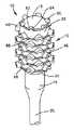
- FIG. 1is a schematic pictorial view of a biological sample collection device constructed in accordance with the present invention
- FIG. 2is a schematic pictorial view of the collection device of FIG. 1 shown in a collapsed position
- FIG. 3is a sectional view of the collection device of FIG. 2 ;
- FIG. 4is an enlarged plan view of a projection or bristle of the collection device of FIG. 1 ;
- FIG. 5is a sectional view of the projection taken along the line 5 - 5 in FIG. 4 ;
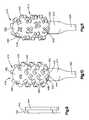
- FIG. 6is a schematic pictorial view of a collection device constructed in accordance with a second embodiment of the present invention.
- FIG. 7is a schematic pictorial view of a collection device constructed in accordance with a third embodiment of the present invention.
- FIG. 8is a schematic pictorial view of a collection device constructed in accordance with a fourth embodiment of the present invention.
- FIG. 9is a side view of a projection of the collection device of FIG. 8 ;
- FIG. 10is a schematic pictorial view of a collection device constructed in accordance with a fifth embodiment of the present invention.
- FIG. 11is a schematic pictorial view of a collection device constructed in accordance with a sixth embodiment of the present invention.
- FIG. 12is a schematic sectional view of a collection device constructed in accordance with a seventh embodiment of the present invention.
- FIG. 13is a schematic sectional view of a collection device constructed in accordance with an eighth embodiment of the present invention.
- FIG. 14is a schematic sectional view of the collection device of FIG. 13 shown in a collapsed position.
- FIG. 15is a schematic pictorial view of a collection device constructed in accordance with a ninth embodiment of the present invention.
- FIGS. 1-5A collection device 10 for the collecting a biological sample constructed in accordance with the present invention is illustrated in FIGS. 1-5 .
- the collection device 10may be used to collect tissue, cells, protein, RNA and/or DNA from a body lumen, such as an esophagus of a patient.
- the tissue, cells, protein, RNA and/or DNA collected from the esophagusmay be used in any one of the methods disclosed in U.S. patent application Ser. No. 14/109,041, U.S. patent application Ser. No. 13/670,155, U.S. patent application Ser. No. 13/263,020, U.S. Pat. Nos. 8,642,271, 8,481,707, 8,415,100, 8,221,977, 7,964,353, and 7,485,420, which are incorporated herein by reference in their entirety.
- the collection device 10includes a generally hollow longitudinally extending collection portion 12 .
- the collection portion 12has a first or proximal axial end portion 14 and a second or distal axial end portion 16 .
- the proximal axial end portion 14 and the distal axial end portion 16may be made of a flexible polymer, such as silicone or polyurethane.
- the distal axial end portion 16has a lower durometer than the proximal axial end portion 14 .
- the distal axial end portion 16may expand and contract.
- the first or proximal axial end portion 14is relatively rigid. Therefore, the proximal end portion 14 has a fixed radial extent.
- the first axial end portion 14 and the second axial end portion 16may be integrally formed as one-piece or may be formed as separate pieces that are connected together in any desire manner.
- the proximal end portion 14is illustrated as having a cylindrical shape, the proximal end portion may have any desired shape.
- the proximal axial end portion 14is connected to a support member 20 , such as a catheter.
- the support member 20may be a tubular member in fluid communication with the interior of the collection portion 12 .
- the proximal axial end portion 14conducts fluid, such as air, from the support member 20 to the distal axial end portion 16 .
- a proximal end of the support 20may be connected to a stopcock and syringe to control the injection of fluid to move the distal end portion 16 between the collapsed and expanded positions.
- the support 20resists collapsing when a vacuum is applied to the support member and resists stretching during withdrawal of the collection device 10 from the collection site.
- the second or distal end portion 16 of the collection portion 12has an expanded or inflated position ( FIG. 1 ) and a collapsed or deflated position ( FIGS. 2-3 ).
- the expanded position shown in FIG. 1may be one of many expanded positions for the distal end portion 16 . It is contemplated that the distal end portion 16 may expand more than shown in FIG. 1 so that the distal end portion obtains a more spherical shape and looks similar to a hot air balloon, see FIG. 15 for example.
- the distal end portion 16has a convex shape, shown in FIG. 1 , when in the expanded or inflated position. The distal end portion 16 may extend radially outward a greater distance than the proximal end portion 14 when in the expanded position.
- the distal end portion 16extends into the first or proximal axial end portion 14 and has a concave shape, shown in FIGS. 2 and 3 , when in the collapsed or deflated position.
- the distal end portion 16may be inverted when in the collapsed position.
- the distal end portion 16extends axially into the interior of the proximal end portion 14 when in the collapsed or deflated position. Therefore, the distal end portion 16 moves axially or longitudinally relative to the proximal end portion 14 when moving between the deflated and inflated positions.
- the distal end portion 16may be biased into the collapsed or deflated position in any desired manner.
- the proximal end portion 14has a relatively high durometer so that the proximal end portion does not collapse when a vacuum is applied to the proximal end portion through the support 20 .
- the shape of the proximal end portion 14does not change when the distal end portion 16 moves between the deflated and inflated positions.
- the proximal end portion 14does not move radially when the distal end portion 16 moves between the deflated and inflated positions.
- the distal end portion 16 of the collection portion 12may be connected to the proximal end portion 14 by a circumferentially extending hinge 30 .
- the hinge 30may be a fold.
- the hinge 30may extend circumferentially around the collection portion 12 .
- the hinge 30defines a distal axial end surface of the collection portion 12 when the distal end portion 16 is in the deflated or collapsed position.
- the distal end portion 16defines an axial end surface of the collection portion 12 when the distal end portion is in the inflated or expanded position.
- the distal end portion 16has an outer surface 32 for collecting tissue when the distal portion is in the expanded position.
- the outer surface 32faces radially outwardly when the distal end portion 16 is in the expanded position and may face radially inwardly when the distal end portion is in the collapsed or inverted position. It is contemplated that the outer surface 32 of the distal end portion 16 may have any desired construction for collecting tissue.
- the outer surface 32 of the distal end portion 16may have a plurality of projections or bristles 40 for collecting tissue.
- the distal end portion 16may have any desired number of projections or bristles 40 .
- the projections or bristles 40may have a V-shape ( FIG. 4 ).
- Each projection 40has a first side 42 and a second side 44 extending from an intersection 48 .
- the first and second sides 42 , 44extend in a generally proximal direction from the intersection 48 when the distal end portion 16 is in the expanded position ( FIG. 1 ).
- the first and second sides 42 , 44extend in a generally distal direction when the distal end portion 16 is in the collapsed or inverted position ( FIGS. 2 and 3 ).
- the first and second sides 42 , 44define a cup 50 for receiving collected biological samples.
- the cup 50faces in a proximal direction when the distal portion 16 is in the expanded position and faces in a distal direction when the distal portion is in the collapsed position.
- the first and second sides 42 , 44may extend at an angle of approximately 90° relative to each other. It is contemplated that the first and second sides 42 and 44 may extend at any desired angle relative to each other. The desired angle may be determined based on the type of biological sample to be collected. Alternatively, the projections 40 may be cup shaped or have a semi-circular shape.
- Each of the projections or bristles 40has side walls 54 and 56 ( FIG. 5 ) that extend radially outward from the outer surface 32 when the distal portion 16 is in the expanded position.
- the side walls 54 and 56extend from the outer surface 32 to a radially outer surface 58 of the projection 40 .
- the side walls 54 and 56taper toward each other as the side walls extend from the outer surface 32 toward the radially outer surface 58 of the projection 40 . It is contemplated that the side walls 54 and 56 may not taper toward each other.
- the distal end portion 16may include a plurality of projections or bristles 60 ( FIG. 1 ) extending from a distal portion of the distal end portion 16 .
- the projections 60have the same general V-shape as the projections 40 and are smaller than the projections 40 .
- the projections 60have first and second sides 62 and 64 that have a length smaller than the first and second sides 42 , 44 of the projections 40 .
- the projections or bristles 40 , 60are arranged in circumferentially extending rows ( FIG. 1 ). It is contemplated that each row has six projections 40 or 60 . It is contemplated that each of the rows may have any desired number of projections 40 or 60 . Each of the projections 40 , 60 is circumferentially offset from the projections on an adjacent row. Ribs 66 extend circumferentially between adjacent projections 40 , 60 in each row. The ribs 66 extend between ends of the sides walls 54 , 56 opposite the intersections 48 .
- the collection portion 12is moved to a collection site within a body lumen, such as an esophagus, with the distal end portion 16 in the collapsed or deflated position.
- the collection portion 12may be swallowed by a patient. It is also contemplated that the patient may be intubated with the collection portion 12 attached to a catheter.
- the distal end portion 16may be held in the collapsed or deflated position by the hinge 30 and/or by applying a vacuum to the collection portion 12 through the support 20 .
- the distal end portion 16may also be held in the collapsed position by a cap 68 or cover that falls off, pops off and/or dissolves when the collection portion 12 reaches the body lumen.
- the support member 20 or cathetermay have depth markings to determine the collection site within the patient's anatomy.
- the distal end portion 16is moved from the collapsed position to the expanded position when the collection portion 12 is at the collection site.
- a pressurized fluidsuch as air, may be applied to the distal end portion 16 to cause the distal end portion to move axially from the collapsed position to the expanded position.
- the collection portion 12is moved in the body lumen to collect a biological sample, such as, tissue, cells, protein, RNA and/or DNA from the collection site when the distal portion is in the expanded position. It is contemplated that the collection portion 12 is only moved in a proximal direction so that the expanded distal end portion 16 engages the collection site to collect biological samples.
- the depth markings on the support member 20 or cathetermay be used as a guide.
- the distal end portion 16is moved from the expanded position to the collapsed or inverted position. The distal end portion 16 may be moved from the expanded position to the collapsed position by applying a vacuum to the collection portion 12 .
- the distal end portion 16does not engage the body lumen and prevents the collected biological samples from being contaminated by tissue from areas along the body lumen different from the collection site.
- the biological samplesare collected via a wash and/or the collection portion 12 or the distal end portion 16 may be cut from the support member 20 and deposited in a biological sample vial.
- FIG. 6A second exemplary embodiment of a collection device constructed in accordance with the present invention is illustrated in FIG. 6 .
- the collection device of FIG. 6is generally similar to the collection device of FIGS. 1-5 . Accordingly, similar numerals will be used to describe similar components.
- a collection device 110( FIG. 6 ) includes a generally hollow longitudinally extending collection portion 112 .
- the collection portion 112has a first or proximal axial end portion 114 and a second or distal axial end portion 116 .
- the distal axial end portion 116may expand and contract.
- the proximal end portion 114is relatively rigid. Therefore, the proximal end portion 114 has a fixed radial extent.
- the first axial end portion 114 and the second axial end portion 116may be integrally formed as one-piece or may be formed as separate pieces that are connected together in any desired manner.
- the proximal axial end portion 114is connected to a support member 120 , such as a catheter.
- the support member 120may be a tubular member in fluid communication with the interior of the collection portion 112 .
- the proximal end portion 114conducts fluid, such as air, from the support member 120 to the distal axial end portion 116 .
- the second or distal end portion 116 of the collection portion 112has an expanded or inflated position ( FIG. 6 ) and a collapsed or deflated position similar to the position shown in FIGS. 2 and 3 .
- the distal end portion 116has a convex shape, shown in FIG. 6 , when in the expanded or inflated position.
- the expanded position shown in FIG. 6may be one of many expanded positions for the distal end portion 116 . It is contemplated that the distal end portion 116 may expand more than shown in FIG. 6 so that the distal end portion obtains a more spherical shape and looks similar to a hot air balloon, see FIG. 15 for example.
- the distal end portion 116extends into the first or proximal end portion 114 and has a concave shape when in the collapsed or deflated position.
- the distal end portion 116may be biased into the collapsed or deflated position in any desired manner. Therefore, the distal end portion 116 moves axially relative to the proximal end portion 114 when moving between the deflated and inflated positions.
- the shape of the proximal end portion 114does not change when the distal end portion 116 moves between the deflated and inflated positions.
- the proximal end portion 114does not move radially when the distal end portion 116 moves between the deflated and inflated positions.
- the distal end portion 116 of the collection portion 112may be connected to the proximal end portion 114 by a circumferentially extending hinge 130 .
- the hinge 130may be a fold.
- the hinge 130may extend circumferentially around the collection portion 112 .
- the hinge 130defines a distal axial end surface of the collection portion 112 when the distal end portion 116 is in the deflated or collapsed position.
- the distal end portion 116defines an axial end surface of the collection portion 112 when the distal end portion is in the inflated or expanded position.
- the distal end portion 116has an outer surface 132 for collecting biological samples.
- the outer surface 132 of the distal end portion 116may have a plurality of projections or ribs 140 for collecting biological samples.
- the ribs 140extend circumferentially around the distal end portion 116 and may extend generally parallel to each other. Although the outer surface 132 is shown as having seven projections or ribs 140 , it is contemplated that the outer surface may have any desired number of ribs.
- the ribs 140may extend radially from the outer surface 132 any distance. It is also contemplated that the ribs 140 may extend different distances from the outer surface 132 .
- FIG. 7A third exemplary embodiment of a collection device constructed in accordance with the present invention is illustrated in FIG. 7 .
- the collection device of FIG. 7is generally similar to the collection devices of FIGS. 1-6 . Accordingly, similar numerals will be used to describe similar components.
- a collection device 210( FIG. 7 ) includes a generally hollow longitudinally extending collection portion 212 .
- the collection portion 212has a first or proximal axial end portion 214 and a second or distal axial end portion 216 .
- the distal axial end portion 216may expand and contract.
- the proximal end portion 214is relatively rigid. Therefore, the proximal end portion 214 has a fixed radial extent.
- the first axial end portion 214 and the second axial end portion 216may be integrally formed as one-piece or may be formed as separate pieces that are connected together in any desired manner.
- the proximal end portion 214has a fixed radial extent.
- the proximal axial end portion 214is connected to a support member 220 , such as a catheter.
- the support member 220may be a tubular member in fluid communication with the interior of the collection portion 212 .
- the proximal axial end portion 214conducts fluid, such as air, from the support member 20 to the distal axial end portion 216 .
- the distal end portion 216 of the collection portion 212has an expanded or inflated position ( FIG. 7 ) and a collapsed or deflated position similar to the position shown in FIGS. 2 and 3 .
- the expanded position shown in FIG. 7may be one of many expanded positions for the distal end portion 216 . It is contemplated that the distal end portion 216 may expand more than shown in FIG. 7 so that the distal end portion obtains a more spherical shape and looks similar to a hot air balloon, see FIG. 15 for example.
- the distal end portion 216has a convex shape, shown in FIG. 7 , when in the expanded or inflated position.
- the distal end portion 216extends into the proximal end portion 214 and has a concave shape when in the collapsed or deflated position. Therefore, the distal end portion 216 moves axially relative to the proximal end portion 214 when moving between the deflated and inflated positions.
- the distal end portion 216may be biased into the collapsed or deflated position in any desired manner.
- the shape of the proximal end portion 214does not change when the distal end portion 216 moves between the deflated and inflated positions.
- the proximal end portion 214does not move radially when the distal end portion 216 moves between the deflated and inflated positions.
- the distal end portion 216 of the collection portion 212may be connected to the proximal end portion 214 by a circumferentially extending hinge 230 .
- the hinge 230may be a fold.
- the hinge 230may extend circumferentially around the collection portion 212 .
- the hinge 230defines a distal axial end surface of the collection portion 212 when the distal end portion 216 is in the deflated or collapsed position.
- the distal end portion 216defines an axial end surface of the collection portion 212 when the distal end portion is in the inflated or expanded position.
- the distal end portion 216has an outer surface 232 for collecting biological samples.
- the outer surface 232 of the distal end portion 216may have a plurality of projections or bristles 240 for collecting biological samples.
- the projections 240have a generally cylindrical shape.
- the outer surface 232may have any desired number of projections 240 .
- the projections 240may extend radially from the outer surface 232 any distance. It is also contemplated that the projections 240 may extend different distances from the outer surface 232 .
- the projections 240may have any desired diameters and may have different diameters.
- FIGS. 8 and 9A fourth exemplary embodiment of a collection device constructed in accordance with the present invention is illustrated in FIGS. 8 and 9 .
- the collection device of FIGS. 8 and 9is generally similar to the collection devices of FIGS. 1-7 . Accordingly, similar numerals will be used to describe similar components.
- a collection device 310( FIGS. 8-9 ) includes a generally hollow longitudinally extending tissue collection portion 312 .
- the collection portion 312has a first or proximal axial end portion 314 and a second or distal axial end portion 316 .
- the distal axial end portion 316may expand and contract.
- the proximal end portion 314is relatively rigid. Therefore, the proximal end portion 314 has a fixed radial extent.
- the first axial end portion 314 and the second axial end portion 316may be integrally formed as one-piece or may be formed as separate pieces that are connected together in any desired manner.
- the proximal end portion 314has a fixed radial extent.
- the proximal axial end portion 314is connected to a support member 320 , such as a catheter.
- the support member 320may be a tubular member in fluid communication with the interior of the collection portion 312 .
- the proximal axial end portion 314conducts fluid from the support member 320 to the distal axial end portion 316 .
- the distal end portion 316 of the collection portion 312has an expanded or inflated position ( FIG. 8 ) and a collapsed or deflated position similar to the position shown in FIGS. 2 and 3 .
- the expanded position shown in FIG. 8may be one of many expanded positions for the distal end portion 316 . It is contemplated that the distal end portion 316 may expand more than shown in FIG. 8 so that the distal end portion obtains a more spherical shape and looks similar to a hot air balloon, see FIG. 15 for example.
- the distal end portion 316has a convex shape, shown in FIG. 8 , when in the expanded or inflated position.
- the distal end portion 316extends into the proximal end portion 314 and has a concave shape when in the collapsed or deflated position. Therefore, the distal end portion 316 moves axially relative to the proximal end portion 314 when moving between the deflated and inflated positions.
- the distal end portion 316may be biased into the collapsed or deflated position in any desired manner.
- the shape of the proximal end portion 314does not change when the distal end portion 316 moves between the deflated and inflated positions.
- the proximal end portion 314does not move radially when the distal end portion 316 moves between the deflated and inflated positions.
- the distal end portion 316 of the collection portion 312may be connected to the proximal end portion 314 by a circumferentially extending hinge 330 .
- the hinge 330may be a fold.
- the hinge 330may extend circumferentially around the collection portion 312 .
- the hinge 330defines a distal axial end surface of the collection portion 312 when the distal end portion 316 is in the deflated or collapsed position.
- the distal end portion 316defines an axial end surface of the collection portion 312 when the distal end portion is in the inflated or expanded position.
- the distal end portion 316has an outer surface 332 for collecting biological samples.
- the outer surface 332is generally cylindrical.
- the outer surface 332has an axially extending surface 334 and an axial end surface 336 .
- the axially extending surface 334 of the outer surface 332may have a plurality of projections or bristles 340 for collecting tissue. It is contemplated that the axial end surface 336 may also include projections 340 .
- Each of the projections 340has a support portion 342 ( FIG. 9 ).
- the support portion 342may have a bi-directional curve shape or S-shape extending radially outward from the outer surface 332 .
- a bi-directional curve shaped or S-shaped portion 344 having a cross-section larger than the support portion 342extends from the support portion, as shown in FIG. 9 .
- the outer surface 332may have any desired number of projections 340 .
- the projections 340may extend radially from the outer surface 332 any distance. It is also contemplated that the projections 340 may extend different distances from the outer surface 332 .
- FIG. 10A fifth exemplary embodiment of a collection device constructed in accordance with the present invention is illustrated in FIG. 10 .
- the collection device of FIG. 10is generally similar to the collection devices of FIGS. 1-9 . Accordingly, similar numerals will be used to describe similar components.
- a collection device 410( FIG. 10 ) includes a generally hollow longitudinally extending collection portion 412 .
- the collection portion 412has a first or proximal axial end portion 414 and a second or distal axial end portion 416 .
- the distal axial end portion 416may expand and contract.
- the proximal end portion 414is relatively rigid. Therefore, the proximal end portion 414 has a fixed radial extent.
- the first axial end portion 414 and the second axial end portion 416may be integrally formed as one-piece or may be formed as separate pieces that are connected together in any desired manner.
- the proximal end portion 414has a fixed radial extent.
- the proximal axial end portion 414is connected to a support member 420 , such as a catheter.
- the support member 420may be a tubular member in fluid communication with the interior of the collection portion 412 .
- the proximal end portion 414conducts fluid, such as air, from the support member 420 to the distal axial end portion 416 .
- the distal end portion 416 of the collection portion 412has an expanded or inflated position ( FIG. 10 ) and a collapsed or deflated position similar to the position shown in FIGS. 2 and 3 .
- the expanded position shown in FIG. 10may be one of many expanded positions for the distal end portion 416 . It is contemplated that the distal end portion 416 may expand more than shown in FIG. 10 so that the distal end portion obtains a more spherical shape and looks similar to a hot air balloon, see FIG. 15 for example.
- the distal end portion 16has a convex shape, shown in FIG. 10 , when in the expanded or inflated position.
- the distal end portion 416extends into the proximal end portion and has a concave shape when in the collapsed or deflated position. Therefore, the distal end portion 416 moves axially relative to the proximal end portion 414 when moving between the deflated and inflated positions.
- the distal end portion 416may be biased into the collapsed or deflated position in any desired manner.
- the shape of the proximal end portion 414does not change when the distal end portion 416 moves between the deflated and inflated positions.
- the proximal end portion 414does not move radially when the distal end portion 416 moves between the deflated and inflated positions.
- the distal end portion 416 of the collection portion 412may be connected to the proximal end portion 414 by a circumferentially extending hinge 430 .
- the hinge 430may be a fold.
- the hinge 430may extend circumferentially around the collection portion 412 .
- the hinge 430defines a distal axial end surface of the collection portion 412 when the distal end portion 416 is in the deflated or collapsed position.
- the distal end portion 416defines an axial end surface of the collection portion 412 when the distal end portion is in the inflated or expanded position.
- the distal end portion 416has an outer surface 432 for collecting biological samples.
- the outer surface 432 of the distal end portion 416may have a plurality of projections or bristles 440 for collecting biological samples.
- the projections or bristles 440may have a V-shape and be generally similar to the V-shaped projections 40 described in connection with the embodiment illustrated in FIGS. 1-5 .
- Each projection 440has a first side 442 and a second side 444 extending in a generally proximal direction from an intersection 448 when the distal end portion 416 is in the expanded position. Therefore, the first and second sides 442 , 444 define a proximally facing cup 450 for receiving collected tissue.
- the first and second sides 442 , 444extend at an angle to each other.
- the first and second sides 442 , 444may extend at an angle of approximately 90° relative to each other. It is contemplated that the first and second sides 442 and 444 may extend at any desired angle relative to each other. The desired angle may be determined based on the type of biological sample to be collected.
- the distal end portion 416may include a plurality of projections or bristles 460 extending from a distal portion of the distal end portion 416 .
- the projections 460have the same general V-shape as the projections 440 .
- the projections 460are smaller than the projections 440 and are located distally to the projections 440 when the distal end portion 416 is in the expanded position.
- FIG. 11A sixth exemplary embodiment of a collection device constructed in accordance with the present invention is illustrated in FIG. 11 .
- the collection device of FIG. 10is generally similar to the collection devices of FIGS. 1-10 . Accordingly, similar numerals will be used to describe similar components.
- a collection device 510( FIG. 11 ) includes a generally hollow longitudinally extending collection portion 512 .
- the collection portion 512has a first or proximal axial end portion 514 and a second or distal axial end portion 516 .
- the distal axial end portion 516may expand and contract.
- the proximal end portion 514is relatively rigid. Therefore, the proximal end portion 514 has a fixed radial extent.
- the first axial end portion 514 and the second axial end portion 516may be integrally formed as one-piece or may be formed as separate pieces that are connected together in any desired manner.
- the proximal end portion 514has a fixed radial extent.
- the proximal axial end portion 514is connected to a support member 520 , such as a catheter.
- the support member 520may be a tubular member in fluid communication with the interior of the collection portion 512 .
- the proximal end portion 514conducts fluid from the support member 520 to the distal axial end portion 516 .
- the distal end portion 516 of the collection portion 512has an expanded or inflated position ( FIG. 11 ) and a collapsed or deflated position similar to the position shown in FIGS. 2 and 3 .
- the expanded position shown in FIG. 11may be one of many expanded positions for the distal end portion 516 . It is contemplated that the distal end portion 516 may expand more than shown in FIG. 11 so that the distal end portion obtains a more spherical shape and looks similar to a hot air balloon, see FIG. 15 for example.
- the distal end portion 16has a convex shape, shown in FIG. 11 , when in the expanded or inflated position.
- the distal end portion 516extends into the proximal end portion 514 and has a concave shape when in the collapsed or deflated position. Therefore, the distal end portion 516 moves axially relative to the proximal end portion 514 when moving between the deflated and inflated positions.
- the distal end portion 516may be biased into the collapsed or deflated position in any desired manner.
- the shape of the proximal end portion 514does not change when the distal end portion 516 moves between the deflated and inflated positions.
- the proximal end portion 514does not move radially when the distal end portion 516 moves between the deflated and inflated positions.
- the distal end portion 516 of the collection portion 512may be connected to the proximal end portion 514 by a circumferentially extending hinge 530 .
- the hinge 530may be a fold.
- the hinge 530may extend circumferentially around the collection portion 512 .
- the hinge 530defines a distal axial end surface of the collection portion 512 when the distal end portion 516 is in the deflated or collapsed position.
- the distal end portion 516defines an axial end surface of the collection portion 512 when the distal end portion is in the inflated or expanded position.
- the distal end portion 516has an outer surface 532 for collecting biological samples.
- the outer surface 532 of the distal end portion 516may have a plurality of projections or bristles 540 for collecting biological samples.
- the projections or bristles 540may have an X-shape.
- the distal end portion 516may include a plurality of projections or bristles 560 extending from a distal portion of the distal end portion 516 .
- the projections 560have the same general X-shape as the projections 540 . However, the projections 560 are smaller than the projections 540 .
- FIG. 12A seventh exemplary embodiment of a collection device constructed in accordance with the present invention is illustrated in FIG. 12 .
- the collection device of FIG. 12is generally similar to the collection devices of FIGS. 1-11 . Accordingly, similar numerals will be used to describe similar components.
- a collection device 610( FIG. 12 ) includes a generally hollow longitudinally extending collection portion 612 .
- the collection portion 612has a first or proximal axial end portion 614 and a second or distal axial end portion 616 .
- the distal axial end portion 616may expand and contract.
- the proximal end portion 614is relatively rigid. Therefore, the proximal end portion 614 has a fixed radial extent.
- the proximal axial end portion 614is connected to a support member, such as a catheter.
- the support membermay be a tubular member in fluid communication with the interior of the collection portion 612 .
- the proximal end portion 614conducts fluid from the support member to the distal end portion 616 .
- the distal end portion 616has a first axial end portion 622 connected to the proximal axial end portion 614 .
- the first end portion 622may be connected to the proximal end portion 614 in any desired manner, such as by using an adhesive.
- the first axial end portion 622engages a shoulder 624 on the proximal axial end portion 614 . Therefore, the collection portion 612 has a smooth outer surface.
- the distal end portion 616 of the collection portion 612has an expanded or inflated position ( FIG. 12 ) and a collapsed or deflated position similar to the position shown in FIGS. 2 and 3 .
- the expanded position shown in FIG. 12may be one of many expanded positions for the distal end portion 616 . It is contemplated that the distal end portion 616 may expand more than shown in FIG. 12 so that the distal end portion obtains a more spherical shape and looks similar to a hot air balloon, see FIG. 15 for example.
- the distal end portion 16has a convex shape, shown in FIG. 12 , when in the expanded or inflated position.
- the distal end portion 616extends into the proximal end portion 614 and has a concave shape when in the collapsed or deflated position. Therefore, the distal end portion 616 moves axially relative to the proximal end portion 614 when moving between the deflated and inflated positions.
- the distal end portion 616may be biased into the collapsed or deflated position in any desired manner.
- the shape of the proximal end portion 614does not change when the distal end portion 616 moves between the deflated and inflated positions.
- the proximal end portion 614does not move radially when the distal end portion 616 moves between the deflated and inflated positions.
- the distal end portion 616 of the collection portion 612may be connected to the proximal end portion 614 at a circumferentially extending hinge 630 .
- the hinge 630may extend circumferentially around the collection portion 612 .
- the hinge 630defines a distal axial end surface of the collection portion 612 when the distal end portion 616 is in the deflated or collapsed position.
- the distal end portion 616defines an axial end surface of the collection portion 612 when the distal end portion is in the inflated or expanded position.
- the distal end portion 616has an outer surface 632 for collecting biological samples. It is contemplated that the outer surface 632 of the distal end portion 616 may have any desired construction for collecting biological samples.
- the outer surface 632 of the distal end portion 616may have a plurality of projections or bristles for collecting biological samples.
- the projections or bristlesmay have any desired shape, such as the shapes shown in FIGS. 1-11 .
- FIGS. 13-14An eighth exemplary embodiment of a collection device constructed in accordance with the present invention is illustrated in FIGS. 13-14 .
- the collection device of FIGS. 13-14is generally similar to the collection devices of FIGS. 1-12 . Accordingly, similar numerals will be used to describe similar components.
- a collection device 710( FIG. 11 ) includes a generally hollow longitudinally extending collection portion 712 .
- the collection portion 712has a first or proximal axial end portion 714 and a second or distal axial end portion 716 .
- the distal axial end portion 716may expand and contract.
- the proximal end portion 714is relatively rigid. Therefore, the proximal end portion 714 has a fixed radial extent.
- the first axial end portion 714 and the second axial end portion 716may be integrally formed as one-piece or may be formed as separate pieces that are connected together in any desired manner.
- the proximal end portion 714has a fixed radial extent.
- the proximal axial end portion 714is connected to a support member 720 .
- the support member 720may be a tubular member in fluid communication with the interior of the collection portion 712 .
- the proximal end portion 714conducts fluid from the support member 720 to the distal end portion 716 .
- the distal end portion 716 of the collection portion 712has an expanded or inflated position ( FIG. 13 ) and a collapsed or deflated position ( FIG. 14 ).
- the expanded position shown in FIG. 13may be one of many expanded positions for the distal end portion 716 . It is contemplated that the distal end portion 716 may expand more than shown in FIG. 13 so that the distal end portion obtains a more spherical shape and looks similar to a hot air balloon, see FIG. 15 for example.
- the distal end portion 716has a convex shape, shown in FIG. 13 , when in the expanded or inflated position.
- the distal end portion 716extends into the proximal end portion 714 and has a concave shape when in the collapsed or deflated position, as shown in FIG. 14 .
- the distal end portion 716only moves axially relative to the proximal end portion 714 when moving between the deflated and inflated positions.
- the distal end portion 716may be biased into the collapsed or deflated position in any desired manner.
- the shape of the proximal end portion 714does not change when the distal end portion 716 moves between the deflated and inflated positions.
- the proximal end portion 714does not move radially when the distal end portion 716 moves between the deflated and inflated positions.
- the distal end portion 716 of the collection portion 712may be connected to the proximal end portion 714 by a circumferentially extending hinge 730 .
- the hinge 730may be a fold.
- the hinge 730may extend circumferentially around the collection portion 712 .
- the hinge 730defines a distal axial end surface of the collection portion 712 when the distal end portion 716 is in the deflated or collapsed position.
- the distal end portion 716defines an axial end surface of the collection portion 712 when the distal end portion is in the inflated or expanded position.
- the distal end portion 716has an outer surface 732 for collecting biological samples. It is contemplated that the outer surface 732 of the distal end portion 716 may have any desired construction for collecting biological samples. The outer surface 732 of the distal end portion 716 may have a plurality of projections or bristles 740 for collecting biological samples. The outer surface 732 may have any desired number of projections 740 .
- FIG. 15A ninth exemplary embodiment of a collection device constructed in accordance with the present invention is illustrated in FIG. 15 .
- the collection device of FIG. 15is generally similar to the collection device of FIGS. 1-14 . Accordingly, similar numerals will be used to describe similar components.
- a collection device 810( FIG. 15 ) includes a generally hollow longitudinally extending collection portion 812 .
- the collection portion 812has a first or proximal axial end portion 814 and a second or distal axial end portion 816 .
- the distal axial end portion 816may expand and contract.
- the proximal end portion 814is relatively rigid. Therefore, the proximal end portion 814 has a fixed radial extent.
- the first axial end portion 814 and the second axial end portion 816may be integrally formed as one-piece or may be formed as separate pieces that are connected together in any desired manner.
- the proximal axial end portion 814is connected to a support member 820 , such as a catheter.
- the support member 820may be a tubular member in fluid communication with the interior of the collection portion 812 .
- the proximal end portion 814conducts fluid, such as air, from the support member 820 to the distal axial end portion 816 .
- the second or distal end portion 816 of the collection portion 812has an expanded or inflated position ( FIG. 15 ) and a collapsed or deflated position similar to the position shown in FIGS. 2 and 3 .
- the distal end portion 816has a convex shape, shown in FIG. 15 , when in the expanded or inflated position.
- the expanded position shown in FIG. 15may be one of many expanded positions for the distal end portion 816 . It is contemplated that the distal end portion 816 may expand less than shown in FIG. 15 so that the distal end portion obtains a more oblong shape and looks similar to the distal end portion 16 shown in FIG. 1 .
- the distal end portion 816extends into the first or proximal end portion 814 and has a concave shape when in the collapsed or deflated position.
- the distal end portion 816may be biased into the collapsed or deflated position in any desired manner. Therefore, the distal end portion 816 moves axially relative to the proximal end portion 814 when moving between the deflated and inflated positions.
- the shape of the proximal end portion 814does not change when the distal end portion 816 moves between the deflated and inflated positions.
- the proximal end portion 814does not move radially when the distal end portion 816 moves between the deflated and inflated positions.
- the distal end portion 816 of the collection portion 812may be connected to the proximal end portion 814 by a circumferentially extending hinge 830 .
- the hinge 830may be a fold.
- the hinge 830may extend circumferentially around the collection portion 812 .
- the hinge 830defines a distal axial end surface of the collection portion 812 when the distal end portion 816 is in the deflated or collapsed position.
- the distal end portion 816defines an axial end surface of the collection portion 812 when the distal end portion is in the inflated or expanded position.
- the distal end portion 816has an outer surface 832 for collecting biological samples.
- the outer surface 832 of the distal end portion 816may have a textured surface or include a plurality of projections or ribs for collecting biological samples.
- Each of the collection portions of the described collection devicesis moved to a collection site within a body lumen, such as an esophagus, with the distal end portion in the collapsed or deflated position.
- the collection portionmay be swallowed by a patient.
- the distal end portionmay be held in the collapsed or deflated position by the hinge and/or by applying a vacuum to the collection portion through the support.
- the distal end portionmay also be held in the collapsed position by a cap 68 or cover that falls off, pops off and/or dissolves when the collection portion reaches the collection site.
- the distal end portionis moved from the collapsed position to the expanded position when the collection portion is at the collection site.
- the collection portionis moved in the body lumen to collect biological samples, such as, tissue, cells, protein, RNA and/or DNA from the collection site when the distal portion is in the expanded position.
- biological samplessuch as, tissue, cells, protein, RNA and/or DNA from the collection site when the distal portion is in the expanded position.
- the distal end portionis moved from the expanded position to the collapsed position. As the collection portion moves out of the body lumen, the distal end portion does not engage the body lumen and prevents the collected biological samples from being contaminated by tissue from areas along the body lumen different from the collection site.
- the collection devices described abovemay be formed as one-piece or formed as separate pieces that are connected together. Also, it is contemplated that the projections or bristles may have any desired shape. Accordingly, the tissue collection devices may have at least one V-shaped projection and/or at least one circumferentially extending rib and/or at least one cylindrical projection and/or at least one bi-directional curved shaped projection and/or at least one X-shaped projection. It is also contemplated that each of the collection devices may have circumferentially extending ribs extending between adjacent projections.
Landscapes
- Health & Medical Sciences (AREA)
- Life Sciences & Earth Sciences (AREA)
- Medical Informatics (AREA)
- Engineering & Computer Science (AREA)
- Biomedical Technology (AREA)
- Heart & Thoracic Surgery (AREA)
- Pathology (AREA)
- Molecular Biology (AREA)
- Surgery (AREA)
- Animal Behavior & Ethology (AREA)
- General Health & Medical Sciences (AREA)
- Public Health (AREA)
- Veterinary Medicine (AREA)
- Media Introduction/Drainage Providing Device (AREA)
- Sampling And Sample Adjustment (AREA)
Abstract
Description
Claims (27)
Priority Applications (1)
| Application Number | Priority Date | Filing Date | Title |
|---|---|---|---|
| US15/103,638US10660621B2 (en) | 2013-12-12 | 2014-12-12 | Device for collecting a biological sample |
Applications Claiming Priority (3)
| Application Number | Priority Date | Filing Date | Title |
|---|---|---|---|
| US201361915029P | 2013-12-12 | 2013-12-12 | |
| US15/103,638US10660621B2 (en) | 2013-12-12 | 2014-12-12 | Device for collecting a biological sample |
| PCT/US2014/070060WO2015089422A1 (en) | 2013-12-12 | 2014-12-12 | Device for collecting a biological sample |
Related Parent Applications (1)
| Application Number | Title | Priority Date | Filing Date |
|---|---|---|---|
| PCT/US2014/070060A-371-Of-InternationalWO2015089422A1 (en) | 2013-12-12 | 2014-12-12 | Device for collecting a biological sample |
Related Child Applications (1)
| Application Number | Title | Priority Date | Filing Date |
|---|---|---|---|
| US16/405,634DivisionUS20190261962A1 (en) | 2013-12-12 | 2019-05-07 | Device for collecting a biological sample |
Publications (2)
| Publication Number | Publication Date |
|---|---|
| US20160317132A1 US20160317132A1 (en) | 2016-11-03 |
| US10660621B2true US10660621B2 (en) | 2020-05-26 |
Family
ID=53371874
Family Applications (7)
| Application Number | Title | Priority Date | Filing Date |
|---|---|---|---|
| US15/103,638Active2035-05-20US10660621B2 (en) | 2013-12-12 | 2014-12-12 | Device for collecting a biological sample |
| US16/405,634PendingUS20190261962A1 (en) | 2013-12-12 | 2019-05-07 | Device for collecting a biological sample |
| US17/643,329AbandonedUS20220096062A1 (en) | 2013-12-12 | 2021-12-08 | Device for collecting a biological sample |
| US17/643,341AbandonedUS20220096064A1 (en) | 2013-12-12 | 2021-12-08 | Device for collecting a biological sample |
| US17/643,320AbandonedUS20220096061A1 (en) | 2013-12-12 | 2021-12-08 | Device for collecting a biological sample |
| US17/643,335ActiveUS12376837B2 (en) | 2013-12-12 | 2021-12-08 | Device for collecting a biological sample |
| US17/643,299AbandonedUS20220096060A1 (en) | 2013-12-12 | 2021-12-08 | Device for collecting a biological sample |
Family Applications After (6)
| Application Number | Title | Priority Date | Filing Date |
|---|---|---|---|
| US16/405,634PendingUS20190261962A1 (en) | 2013-12-12 | 2019-05-07 | Device for collecting a biological sample |
| US17/643,329AbandonedUS20220096062A1 (en) | 2013-12-12 | 2021-12-08 | Device for collecting a biological sample |
| US17/643,341AbandonedUS20220096064A1 (en) | 2013-12-12 | 2021-12-08 | Device for collecting a biological sample |
| US17/643,320AbandonedUS20220096061A1 (en) | 2013-12-12 | 2021-12-08 | Device for collecting a biological sample |
| US17/643,335ActiveUS12376837B2 (en) | 2013-12-12 | 2021-12-08 | Device for collecting a biological sample |
| US17/643,299AbandonedUS20220096060A1 (en) | 2013-12-12 | 2021-12-08 | Device for collecting a biological sample |
Country Status (5)
| Country | Link |
|---|---|
| US (7) | US10660621B2 (en) |
| EP (3) | EP4437972A3 (en) |
| AU (2) | AU2014361829B2 (en) |
| CA (2) | CA3147619A1 (en) |
| WO (1) | WO2015089422A1 (en) |
Cited By (6)
| Publication number | Priority date | Publication date | Assignee | Title |
|---|---|---|---|---|
| WO2021242878A1 (en) | 2020-05-27 | 2021-12-02 | Case Western Reserve University | Biological sampling device |
| WO2021257058A1 (en) | 2020-06-16 | 2021-12-23 | Case Western Reverse University | Device for biological cell collection and method of use |
| WO2023278758A1 (en)* | 2021-07-02 | 2023-01-05 | Case Western Reserve University | Biological sampling method |
| WO2023278776A1 (en)* | 2021-07-02 | 2023-01-05 | Case Western Reserve University | Biological sampling method |
| US12262879B2 (en) | 2020-06-16 | 2025-04-01 | Case Western Reserve University | Device for biological cell collection and method of use |
| US12376837B2 (en)* | 2013-12-12 | 2025-08-05 | Case Western Reserve University | Device for collecting a biological sample |
Families Citing this family (20)
| Publication number | Priority date | Publication date | Assignee | Title |
|---|---|---|---|---|
| US10639016B2 (en) | 2013-02-01 | 2020-05-05 | Boston Scientific Scimed, Inc. | Methods and devices for Fallopian tube diagnostics |
| CA2899881A1 (en) | 2013-02-01 | 2014-08-07 | Nvision Medical Corporation | Methods and devices for fallopian tube diagnostics |
| GB201415653D0 (en)* | 2014-09-04 | 2014-10-22 | Univ Leeds | Orthopaedic medical device |
| HU230970B1 (en)* | 2015-08-31 | 2019-06-28 | Dolhay Kft. | Sampling tool for secretion |
| WO2017070201A1 (en)* | 2015-10-21 | 2017-04-27 | Boston Scientific Scimed, Inc. | Tissue sample device and methods |
| WO2017147586A1 (en)* | 2016-02-25 | 2017-08-31 | Nvision Medical Corporation | Methods and devices for fallopian tube diagnostics |
| WO2018009535A1 (en) | 2016-07-06 | 2018-01-11 | Case Western Reserve University | Methods and compositions for detecting esophageal neoplasias and/or metaplasias in the esophagus |
| CA3062305A1 (en)* | 2017-05-03 | 2018-11-08 | Case Western Reserve University | Device for collecting a biological sample |
| WO2018222728A1 (en)* | 2017-05-31 | 2018-12-06 | 4Women Health, Inc. | Self-collection device and kit for collecting cervical and vaginal cells |
| CN108209980B (en)* | 2018-01-25 | 2021-05-11 | 山东省日照市人民医院 | Sampling device for diagnosis of gastroenterology |
| US11878116B2 (en)* | 2019-11-01 | 2024-01-23 | Iowa State University Research Foundation, Inc. | Tracheo-bronchial sampling device |
| CA3180452A1 (en) | 2020-05-27 | 2021-12-02 | Sanford D. Markowitz | Compositions and methods for preserving dna methylation |
| WO2021237293A1 (en)* | 2020-05-27 | 2021-12-02 | 3DMEDiTech Pty Ltd | Swab |
| US20230363745A1 (en)* | 2020-09-16 | 2023-11-16 | Bionlifescience, Inc. | Sample collection stick |
| WO2022104433A1 (en)* | 2020-11-19 | 2022-05-27 | 3DMEDiTech Pty Ltd | Mucus collection device |
| EP4029456A1 (en)* | 2021-01-14 | 2022-07-20 | Albireo Biomedical sp. z o.o. | A stick for collecting and transferring biological material |
| US20220287694A1 (en)* | 2021-03-09 | 2022-09-15 | Jovanni Neblett-Blackmon | Comfortable Patient Collected Home PAP |
| CN113017714B (en)* | 2021-03-15 | 2021-11-16 | 深圳市康达安生物科技有限公司 | Cervical brush and manufacturing process thereof |
| CN113995447A (en)* | 2021-11-05 | 2022-02-01 | 上海科罡医疗技术有限公司 | Saccular biological sampler |
| WO2024006304A1 (en)* | 2022-06-28 | 2024-01-04 | Brent Harris | Devices and methods with expandable brush for cervical and anala self-collecting specimens |
Citations (31)
| Publication number | Priority date | Publication date | Assignee | Title |
|---|---|---|---|---|
| US3400708A (en) | 1965-11-24 | 1968-09-10 | Robert A. Scheidt | Cytologic endocrine evaluation device |
| US3664328A (en) | 1971-04-28 | 1972-05-23 | Henry Dinwoodey Moyle Jr | Cancer test specimen gathering device |
| US4467816A (en) | 1978-03-23 | 1984-08-28 | Battelle-Institut E.V. | Device for collecting cell material |
| WO1987005523A1 (en) | 1986-03-13 | 1987-09-24 | Siemens, Herman, Werner | Tubular devices for introduction into body orifices |
| WO1989006360A1 (en) | 1988-01-11 | 1989-07-13 | Elmex Ltd. | Stool sampling tube suitable for automatic processing |
| WO1994023787A1 (en) | 1993-04-22 | 1994-10-27 | Rammler David H | Sampling balloon catheter |
| US5445164A (en)* | 1993-05-11 | 1995-08-29 | Gynetech, Inc. | Cervical tissue sampling device |
| US20020173816A1 (en) | 2001-04-16 | 2002-11-21 | Pro Duct Health, Inc. | Medical instrument with an atraumatic end |
| US20030208134A1 (en) | 2001-05-07 | 2003-11-06 | Secrest Dean J. | Barrett's esophagus cytology device |
| WO2004110300A2 (en) | 2001-07-25 | 2004-12-23 | Disc Orthopaedic Technologies Inc. | Deformable tools and implants |
| US20050215959A1 (en) | 2004-03-24 | 2005-09-29 | Children's Memorial Hospital. | Delivery devices and methods of delivering liquids and nutrition to patients |
| WO2006003447A1 (en) | 2004-07-07 | 2006-01-12 | Colonix Limited | Colorectal cell sampling device |
| US7004913B1 (en)* | 2001-05-04 | 2006-02-28 | Cdx Laboratories, Inc. | Retractable brush for use with endoscope for brush biopsy |
| US20060184191A1 (en) | 2005-02-11 | 2006-08-17 | Boston Scientific Scimed, Inc. | Cutting balloon catheter having increased flexibility regions |
| US20080188769A1 (en) | 2007-02-07 | 2008-08-07 | Li-Cheng Lu | Foldable Brush Self-sampling Device |
| US20090024060A1 (en) | 2007-04-16 | 2009-01-22 | Darrigrand William A | Sample collector |
| US8068897B1 (en)* | 1999-03-01 | 2011-11-29 | Gazdzinski Robert F | Endoscopic smart probe and method |
| WO2012162610A1 (en) | 2011-05-26 | 2012-11-29 | Adn International, Llc | Expandable device for tissue collection from an aerodigestive body lumen |
| US20130066346A1 (en) | 2011-09-13 | 2013-03-14 | John P. Pigott | Intravascular Catheter Having An Expandable Incising Portion |
| WO2013116560A1 (en) | 2012-01-31 | 2013-08-08 | The Trustees Of Columbia University In The City Of New York | Tissue sampling devices, methods, and systems |
| US20130267870A1 (en) | 2012-04-06 | 2013-10-10 | Histologics Llc | Cell and tissue collection method and device |
| US8668654B1 (en) | 2013-03-13 | 2014-03-11 | Sanovas, Inc. | Cytological brushing system |
| WO2014121207A1 (en) | 2013-02-01 | 2014-08-07 | Nvision Medical Corporation | Methods and devices for fallopian tube diagnostics |
| US20140296742A1 (en) | 2011-11-01 | 2014-10-02 | The Johns Hopkins University | Method and Device for Endoscopic Abrasion |
| WO2015089422A1 (en) | 2013-12-12 | 2015-06-18 | Case Western Reserve University | Device for collecting a biological sample |
| US20150289752A1 (en) | 2014-04-10 | 2015-10-15 | Daniel Rachlin | Tethered endoscope |
| US9339259B2 (en) | 2004-07-07 | 2016-05-17 | Colonix Limited | Colorectal cell sampling device |
| WO2016178189A1 (en) | 2015-05-06 | 2016-11-10 | Caldbeck Overseas Limited | Clinical sampling device |
| US20170112477A1 (en) | 2015-10-21 | 2017-04-27 | Boston Scientific Scimed, Inc. | Tissue sample device and methods |
| WO2017147586A1 (en) | 2016-02-25 | 2017-08-31 | Nvision Medical Corporation | Methods and devices for fallopian tube diagnostics |
| WO2018204659A1 (en) | 2017-05-03 | 2018-11-08 | Case Western Reserve University | Device for collecting a biological sample |
Family Cites Families (58)
| Publication number | Priority date | Publication date | Assignee | Title |
|---|---|---|---|---|
| US1098222A (en)* | 1913-10-29 | 1914-05-26 | Edward F Heffner | Sanitary medicament-ejector for rectal, vaginal, and nasal use. |
| US2701559A (en)* | 1951-08-02 | 1955-02-08 | William A Cooper | Apparatus for exfoliating and collecting diagnostic material from inner walls of hollow viscera |
| ZA761847B (en) | 1976-03-26 | 1977-10-26 | A Baskind | Detection of oesophageal cancer |
| US4481952A (en)* | 1978-03-22 | 1984-11-13 | Jerzy Pawelec | Device for the study of the alimentary canal |
| JPS5964065A (en) | 1982-10-04 | 1984-04-11 | テルモ株式会社 | Baloon cathetel |
| JPS6052817A (en) | 1983-09-02 | 1985-03-26 | Olympus Optical Co Ltd | Sample drawing implement for endoscope |
| US4979951A (en) | 1984-05-30 | 1990-12-25 | Simpson John B | Atherectomy device and method |
| US4627444A (en) | 1985-06-20 | 1986-12-09 | Regents Of The University Of Minnesota | Device for sampling tissues and fluids from bodily cavities |
| US4735214A (en)* | 1986-09-05 | 1988-04-05 | Berman Irwin R | Gastrointestinal diagnostic capsule and method of use |
| US5318587A (en) | 1989-08-25 | 1994-06-07 | C. R. Bard, Inc. | Pleated balloon dilatation catheter and method of use |
| US5879499A (en) | 1996-06-17 | 1999-03-09 | Heartport, Inc. | Method of manufacture of a multi-lumen catheter |
| CN1352538A (en)* | 1999-03-09 | 2002-06-05 | 先进警戒股份有限公司 | Biopsy device and method of obtaining a biopsy sample |
| AU3749400A (en) | 1999-03-16 | 2000-10-04 | Chase Medical Inc. | Catheter having varying resiliency balloon |
| US6786889B1 (en) | 1999-03-31 | 2004-09-07 | Scimed Life Systems, Inc | Textured and/or marked balloon for stent delivery |
| GB2379389B (en) | 2001-09-06 | 2005-03-30 | Mediplus Ltd | Multi-lumen manometry catheters |
| US20040127932A1 (en)* | 2002-09-12 | 2004-07-01 | Shah Tilak M. | Dip-molded polymeric medical devices with reverse thickness gradient, and method of making same |
| WO2005017207A2 (en) | 2003-08-14 | 2005-02-24 | Case Western Reserve University | Methods and compositions for detecting colon cancers |
| US8415100B2 (en) | 2003-08-14 | 2013-04-09 | Case Western Reserve University | Methods and compositions for detecting gastrointestinal and other cancers |
| JP3852033B2 (en) | 2003-12-12 | 2006-11-29 | 独立行政法人科学技術振興機構 | Active tube and active tube system |
| JP4982637B2 (en) | 2004-12-15 | 2012-07-25 | クック メディカル テクノロジーズ エルエルシー | Flexible surgical needle device |
| JP2008541851A (en) | 2005-05-27 | 2008-11-27 | アメディカ コーポレイション | Artificial knee joint with ceramic tibial components |
| US8038595B2 (en) | 2006-01-25 | 2011-10-18 | Beth Israel Deaconess Medical Center | Devices and methods for tissue transplant and regeneration |
| JP4088692B2 (en) | 2006-02-23 | 2008-05-21 | 国立大学法人山口大学 | Stylet |
| RU2417732C2 (en) | 2006-10-10 | 2011-05-10 | Байосенс Уэбстер, Инк. | Oesophageal mapping catheter |
| US8840566B2 (en)* | 2007-04-02 | 2014-09-23 | University Of Washington | Catheter with imaging capability acts as guidewire for cannula tools |
| US20090118641A1 (en) | 2007-11-02 | 2009-05-07 | Jacques Van Dam | Devices, Methods, and Kits for a Biopsy Device |
| US20100249752A1 (en) | 2007-12-21 | 2010-09-30 | Coloplast A/S | Pressure-controlled balloon catheter |
| US20090299374A1 (en) | 2008-06-02 | 2009-12-03 | Loma Vista Medical, Inc. | Inflatable medical devices |
| US20110071428A1 (en)* | 2008-08-01 | 2011-03-24 | The Penn State Research Foundation | Biopsy device |
| US20120164638A1 (en) | 2009-04-06 | 2012-06-28 | Case Western Reserve University | Digital Quantification of DNA Methylation |
| US20100286593A1 (en) | 2009-05-11 | 2010-11-11 | Hotspur Technologies, Inc. | Balloon catheter with cutting features and methods for use |
| US8642271B2 (en) | 2009-08-27 | 2014-02-04 | Case Western Reserve University | Aberrant methylation of C6Orf150 DNA sequences in human colorectal cancer |
| US9072499B2 (en)* | 2010-03-26 | 2015-07-07 | Dna Genotek Inc. | Sample collection tool |
| CN202104944U (en) | 2011-05-19 | 2012-01-11 | 麦克奥迪(厦门)医疗诊断系统有限公司 | Disposable esophageal cast-off cell sampler |
| WO2013040201A2 (en) | 2011-09-14 | 2013-03-21 | Boston Scientific Scimed, Inc. | Ablation device with multiple ablation modes |
| GB201120162D0 (en) | 2011-11-22 | 2012-01-04 | Medical Res Council | Methods for detection of benign conditions |
| US20150057517A1 (en) | 2012-03-27 | 2015-02-26 | University Of Utah Research Foundation | Sample capture device and systems and methods of using same |
| US9351779B2 (en)* | 2013-01-25 | 2016-05-31 | Kyphon SÀRL | Expandable device and methods of use |
| EP3378523B1 (en) | 2013-03-15 | 2020-04-15 | Abbott Cardiovascular Systems, Inc. | Reduced material tip for catheter and method of forming same |
| AT514209B1 (en) | 2013-04-16 | 2015-02-15 | Mitterer Stephan | Device for sampling |
| JP6314612B2 (en) | 2014-04-03 | 2018-04-25 | ニプロ株式会社 | Stomach arrival confirmation device |
| GB201415653D0 (en)* | 2014-09-04 | 2014-10-22 | Univ Leeds | Orthopaedic medical device |
| US10751033B2 (en) | 2014-09-18 | 2020-08-25 | Covidien Lp | Use of expansion-force elements in a compressible cell collection device |
| US20180116645A1 (en) | 2015-04-28 | 2018-05-03 | Michael NOSLER | Stylet and Needle Combinations Used to Collect Tissue Samples During Endoscopic Procedures |
| US20180146839A1 (en) | 2015-06-24 | 2018-05-31 | The Regents Of The University Of Colorado, A Body Corporate | Multi-use scope |
| JP6753655B2 (en) | 2015-08-21 | 2020-09-09 | 学校法人関西医科大学 | Medical equipment |
| CN105193459A (en) | 2015-09-22 | 2015-12-30 | 成都蜀云达科技有限公司 | Biopsy sampler for digestive system department |
| JP6582825B2 (en) | 2015-09-30 | 2019-10-02 | ニプロ株式会社 | Thrombus aspiration catheter and stylet |
| US10541736B2 (en) | 2017-09-12 | 2020-01-21 | Mediatek Inc. | Codebook-based uplink transmission in wireless communications |
| US11291382B2 (en) | 2018-06-01 | 2022-04-05 | Diversatek Healthcare, Inc. | System and method for detecting and measuring the condition of intraluminal esophageal mucosa |
| EP3597112A1 (en) | 2018-07-17 | 2020-01-22 | Erbe Elektromedizin GmbH | Biopsy material recovery device |
| US11723631B2 (en) | 2020-04-10 | 2023-08-15 | Orlando Health, Inc. | Brush for non-invasive biopsy |
| CN115802951A (en) | 2020-05-27 | 2023-03-14 | 凯斯西储大学 | Biological sampling device |
| US12262879B2 (en) | 2020-06-16 | 2025-04-01 | Case Western Reserve University | Device for biological cell collection and method of use |
| US20230000474A1 (en) | 2021-07-02 | 2023-01-05 | Case Western Reserve University | Biological sampling device and method of use |
| WO2023278776A1 (en) | 2021-07-02 | 2023-01-05 | Case Western Reserve University | Biological sampling method |
| JP2025052817A (en) | 2023-09-25 | 2025-04-07 | 株式会社ジェイエスピー | Thermoplastic polymer foamed beads, thermoplastic polymer foamed bead molded product, and method for identifying thermoplastic polymer foamed beads or thermoplastic polymer foamed bead molded product |
| JP7473733B1 (en) | 2023-10-05 | 2024-04-23 | 貴 川上 | Foldable bathtub |
- 2014
- 2014-12-12EPEP24178269.7Apatent/EP4437972A3/enactivePending
- 2014-12-12CACA3147619Apatent/CA3147619A1/enactivePending
- 2014-12-12EPEP19208108.1Apatent/EP3622894B1/enactiveActive
- 2014-12-12EPEP14870556.9Apatent/EP3079598B1/enactiveActive
- 2014-12-12WOPCT/US2014/070060patent/WO2015089422A1/enactiveApplication Filing
- 2014-12-12AUAU2014361829Apatent/AU2014361829B2/enactiveActive
- 2014-12-12CACA2933550Apatent/CA2933550C/enactiveActive
- 2014-12-12USUS15/103,638patent/US10660621B2/enactiveActive
- 2019
- 2019-05-07USUS16/405,634patent/US20190261962A1/enactivePending
- 2019-10-22AUAU2019253820Apatent/AU2019253820B2/enactiveActive
- 2021
- 2021-12-08USUS17/643,329patent/US20220096062A1/ennot_activeAbandoned
- 2021-12-08USUS17/643,341patent/US20220096064A1/ennot_activeAbandoned
- 2021-12-08USUS17/643,320patent/US20220096061A1/ennot_activeAbandoned
- 2021-12-08USUS17/643,335patent/US12376837B2/enactiveActive
- 2021-12-08USUS17/643,299patent/US20220096060A1/ennot_activeAbandoned
Patent Citations (42)
| Publication number | Priority date | Publication date | Assignee | Title |
|---|---|---|---|---|
| US3400708A (en) | 1965-11-24 | 1968-09-10 | Robert A. Scheidt | Cytologic endocrine evaluation device |
| US3664328A (en) | 1971-04-28 | 1972-05-23 | Henry Dinwoodey Moyle Jr | Cancer test specimen gathering device |
| US4467816A (en) | 1978-03-23 | 1984-08-28 | Battelle-Institut E.V. | Device for collecting cell material |
| WO1987005523A1 (en) | 1986-03-13 | 1987-09-24 | Siemens, Herman, Werner | Tubular devices for introduction into body orifices |
| WO1989006360A1 (en) | 1988-01-11 | 1989-07-13 | Elmex Ltd. | Stool sampling tube suitable for automatic processing |
| WO1994023787A1 (en) | 1993-04-22 | 1994-10-27 | Rammler David H | Sampling balloon catheter |
| US5445164A (en)* | 1993-05-11 | 1995-08-29 | Gynetech, Inc. | Cervical tissue sampling device |
| US8068897B1 (en)* | 1999-03-01 | 2011-11-29 | Gazdzinski Robert F | Endoscopic smart probe and method |
| US20020173816A1 (en) | 2001-04-16 | 2002-11-21 | Pro Duct Health, Inc. | Medical instrument with an atraumatic end |
| US7004913B1 (en)* | 2001-05-04 | 2006-02-28 | Cdx Laboratories, Inc. | Retractable brush for use with endoscope for brush biopsy |
| US20030208134A1 (en) | 2001-05-07 | 2003-11-06 | Secrest Dean J. | Barrett's esophagus cytology device |
| US7108661B2 (en) | 2001-05-07 | 2006-09-19 | United States Endoscopy Group, Inc. | Method and collection device for Barrett's esophagus cells |
| WO2004110300A3 (en) | 2001-07-25 | 2005-06-30 | Disc Orthopaedic Technologies | Deformable tools and implants |
| US20060271061A1 (en) | 2001-07-25 | 2006-11-30 | Disc-O-Tech, Ltd. | Deformable tools and implants |
| WO2004110300A2 (en) | 2001-07-25 | 2004-12-23 | Disc Orthopaedic Technologies Inc. | Deformable tools and implants |
| US20050215959A1 (en) | 2004-03-24 | 2005-09-29 | Children's Memorial Hospital. | Delivery devices and methods of delivering liquids and nutrition to patients |
| WO2006003447A1 (en) | 2004-07-07 | 2006-01-12 | Colonix Limited | Colorectal cell sampling device |
| US20080097238A1 (en) | 2004-07-07 | 2008-04-24 | Alexandre Loktionov | Colorectal Cell Sampling Device |
| US9339259B2 (en) | 2004-07-07 | 2016-05-17 | Colonix Limited | Colorectal cell sampling device |
| US20060184191A1 (en) | 2005-02-11 | 2006-08-17 | Boston Scientific Scimed, Inc. | Cutting balloon catheter having increased flexibility regions |
| US20080188769A1 (en) | 2007-02-07 | 2008-08-07 | Li-Cheng Lu | Foldable Brush Self-sampling Device |
| US20090024060A1 (en) | 2007-04-16 | 2009-01-22 | Darrigrand William A | Sample collector |
| US20140171828A1 (en) | 2011-05-26 | 2014-06-19 | Adn International, Llc | Expandable Device for Tissue Collection From an Aerodigestive Body Lumen |
| WO2012162610A1 (en) | 2011-05-26 | 2012-11-29 | Adn International, Llc | Expandable device for tissue collection from an aerodigestive body lumen |
| US20130066346A1 (en) | 2011-09-13 | 2013-03-14 | John P. Pigott | Intravascular Catheter Having An Expandable Incising Portion |
| WO2013040160A1 (en) | 2011-09-13 | 2013-03-21 | Pigott John P | Intravascular catheter having an expandable incising portion |
| US20140296742A1 (en) | 2011-11-01 | 2014-10-02 | The Johns Hopkins University | Method and Device for Endoscopic Abrasion |
| WO2013116560A1 (en) | 2012-01-31 | 2013-08-08 | The Trustees Of Columbia University In The City Of New York | Tissue sampling devices, methods, and systems |
| US20130267870A1 (en) | 2012-04-06 | 2013-10-10 | Histologics Llc | Cell and tissue collection method and device |
| WO2014121207A1 (en) | 2013-02-01 | 2014-08-07 | Nvision Medical Corporation | Methods and devices for fallopian tube diagnostics |
| US8668654B1 (en) | 2013-03-13 | 2014-03-11 | Sanovas, Inc. | Cytological brushing system |
| WO2014143459A1 (en) | 2013-03-13 | 2014-09-18 | Sanovas, Inc. | Cytological brushing system |
| WO2015089422A1 (en) | 2013-12-12 | 2015-06-18 | Case Western Reserve University | Device for collecting a biological sample |
| US20160317132A1 (en) | 2013-12-12 | 2016-11-03 | Case Western Reserve University | Device for collecting a biological sample |
| US20190261962A1 (en) | 2013-12-12 | 2019-08-29 | Case Western Reserve University | Device for collecting a biological sample |
| US20150289752A1 (en) | 2014-04-10 | 2015-10-15 | Daniel Rachlin | Tethered endoscope |
| WO2016178189A1 (en) | 2015-05-06 | 2016-11-10 | Caldbeck Overseas Limited | Clinical sampling device |
| US20180161020A1 (en) | 2015-05-06 | 2018-06-14 | Caldbeck Overseas Limited | Clinical sampling device |
| US20170112477A1 (en) | 2015-10-21 | 2017-04-27 | Boston Scientific Scimed, Inc. | Tissue sample device and methods |
| WO2017147586A1 (en) | 2016-02-25 | 2017-08-31 | Nvision Medical Corporation | Methods and devices for fallopian tube diagnostics |
| WO2018204659A1 (en) | 2017-05-03 | 2018-11-08 | Case Western Reserve University | Device for collecting a biological sample |
| US20200077992A1 (en) | 2017-05-03 | 2020-03-12 | Case Western Reserve University | Device for Collecting a Biological Sample |
Non-Patent Citations (3)
| Title |
|---|
| Australian Office action for Application No. 2014361829, dated Aug. 21, 2018. |
| International Search Report in International Patent Application No. PCT/US2014/070060 dated Mar. 17, 2015. |
| Supplementary European Search Report for Application No. 14870556.9-1664, dated Jul. 10, 2017. |
Cited By (6)
| Publication number | Priority date | Publication date | Assignee | Title |
|---|---|---|---|---|
| US12376837B2 (en)* | 2013-12-12 | 2025-08-05 | Case Western Reserve University | Device for collecting a biological sample |
| WO2021242878A1 (en) | 2020-05-27 | 2021-12-02 | Case Western Reserve University | Biological sampling device |
| WO2021257058A1 (en) | 2020-06-16 | 2021-12-23 | Case Western Reverse University | Device for biological cell collection and method of use |
| US12262879B2 (en) | 2020-06-16 | 2025-04-01 | Case Western Reserve University | Device for biological cell collection and method of use |
| WO2023278758A1 (en)* | 2021-07-02 | 2023-01-05 | Case Western Reserve University | Biological sampling method |
| WO2023278776A1 (en)* | 2021-07-02 | 2023-01-05 | Case Western Reserve University | Biological sampling method |
Also Published As
| Publication number | Publication date |
|---|---|
| US20220096063A1 (en) | 2022-03-31 |
| EP3622894A1 (en) | 2020-03-18 |
| EP4437972A2 (en) | 2024-10-02 |
| US12376837B2 (en) | 2025-08-05 |
| AU2019253820A1 (en) | 2019-11-14 |
| US20160317132A1 (en) | 2016-11-03 |
| US20220096064A1 (en) | 2022-03-31 |
| EP3079598B1 (en) | 2022-03-16 |
| EP3079598A1 (en) | 2016-10-19 |
| US20220096062A1 (en) | 2022-03-31 |
| EP4437972A3 (en) | 2024-12-04 |
| US20220096060A1 (en) | 2022-03-31 |
| US20220096061A1 (en) | 2022-03-31 |
| EP3079598A4 (en) | 2017-11-15 |
| AU2019253820B2 (en) | 2020-09-10 |
| CA2933550C (en) | 2022-04-26 |
| EP3622894B1 (en) | 2024-05-29 |
| CA2933550A1 (en) | 2015-06-18 |
| WO2015089422A1 (en) | 2015-06-18 |
| CA3147619A1 (en) | 2015-06-18 |
| US20190261962A1 (en) | 2019-08-29 |
| AU2014361829B2 (en) | 2019-07-25 |
| AU2014361829A1 (en) | 2016-06-30 |
Similar Documents
| Publication | Publication Date | Title |
|---|---|---|
| US20220096063A1 (en) | Device for collecting a biological sample | |
| US20200077992A1 (en) | Device for Collecting a Biological Sample | |
| US12262879B2 (en) | Device for biological cell collection and method of use | |
| RU2007139498A (en) | TAMPON DEVICE WITH APPLICATOR | |
| US20210369256A1 (en) | Biological sampling device and method of use | |
| EP4164503A1 (en) | Device for biological cell collection and method of use |
Legal Events
| Date | Code | Title | Description |
|---|---|---|---|
| AS | Assignment | Owner name:CASE WESTERN RESERVE UNIVERSITY, OHIO Free format text:ASSIGNMENT OF ASSIGNORS INTEREST;ASSIGNORS:MARKOWITZ, SANFORD;CHAK, AMITABH;WILLIS, JOSEPH;AND OTHERS;SIGNING DATES FROM 20150106 TO 20150110;REEL/FRAME:045798/0663 | |
| STPP | Information on status: patent application and granting procedure in general | Free format text:FINAL REJECTION MAILED | |
| STPP | Information on status: patent application and granting procedure in general | Free format text:RESPONSE AFTER FINAL ACTION FORWARDED TO EXAMINER | |
| STPP | Information on status: patent application and granting procedure in general | Free format text:NOTICE OF ALLOWANCE MAILED -- APPLICATION RECEIVED IN OFFICE OF PUBLICATIONS | |
| STCB | Information on status: application discontinuation | Free format text:ABANDONMENT FOR FAILURE TO CORRECT DRAWINGS/OATH/NONPUB REQUEST | |
| STPP | Information on status: patent application and granting procedure in general | Free format text:PUBLICATIONS -- ISSUE FEE PAYMENT VERIFIED | |
| STCF | Information on status: patent grant | Free format text:PATENTED CASE | |
| AS | Assignment | Owner name:ALTO OPPORTUNITY MASTER FUND, SPC - SEGREGATED MASTER PORTFOLIO B, NEW YORK Free format text:SECURITY INTEREST;ASSIGNORS:LUCID DIAGNOSTICS INC.;LUCIDDX LABS INC.;CAPNOSTICS, LLC;REEL/FRAME:063145/0503 Effective date:20230321 | |
| MAFP | Maintenance fee payment | Free format text:PAYMENT OF MAINTENANCE FEE, 4TH YR, SMALL ENTITY (ORIGINAL EVENT CODE: M2551); ENTITY STATUS OF PATENT OWNER: SMALL ENTITY Year of fee payment:4 | |
| AS | Assignment | Owner name:CAPNOSTICS, LLC, NEW YORK Free format text:RELEASE BY SECURED PARTY;ASSIGNOR:ALTO OPPORTUNITY MASTER FUND, SPC - SEGREGATED MASTER PORTFOLIO B;REEL/FRAME:069874/0372 Effective date:20241127 Owner name:LUCIDDX LABS INC., CALIFORNIA Free format text:RELEASE BY SECURED PARTY;ASSIGNOR:ALTO OPPORTUNITY MASTER FUND, SPC - SEGREGATED MASTER PORTFOLIO B;REEL/FRAME:069874/0372 Effective date:20241127 Owner name:LUCID DIAGNOSTICS INC., NEW YORK Free format text:RELEASE BY SECURED PARTY;ASSIGNOR:ALTO OPPORTUNITY MASTER FUND, SPC - SEGREGATED MASTER PORTFOLIO B;REEL/FRAME:069874/0372 Effective date:20241127 |