US10660550B2 - Implantable sensor apparatus and methods - Google Patents
Implantable sensor apparatus and methodsDownload PDFInfo
- Publication number
- US10660550B2 US10660550B2US14/982,346US201514982346AUS10660550B2US 10660550 B2US10660550 B2US 10660550B2US 201514982346 AUS201514982346 AUS 201514982346AUS 10660550 B2US10660550 B2US 10660550B2
- Authority
- US
- United States
- Prior art keywords
- sensor
- tissue
- living
- cavity
- sensor apparatus
- Prior art date
- Legal status (The legal status is an assumption and is not a legal conclusion. Google has not performed a legal analysis and makes no representation as to the accuracy of the status listed.)
- Active, expires
Links
- 238000000034methodMethods0.000titleclaimsabstractdescription111
- 238000002513implantationMethods0.000claimsabstractdescription99
- WQZGKKKJIJFFOK-GASJEMHNSA-NGlucoseNatural productsOC[C@H]1OC(O)[C@H](O)[C@@H](O)[C@@H]1OWQZGKKKJIJFFOK-GASJEMHNSA-N0.000claimsabstractdescription35
- 210000003195fasciaAnatomy0.000claimsabstractdescription35
- 239000008103glucoseSubstances0.000claimsabstractdescription35
- 230000000694effectsEffects0.000claimsabstractdescription19
- QVGXLLKOCUKJST-UHFFFAOYSA-Natomic oxygenChemical compound[O]QVGXLLKOCUKJST-UHFFFAOYSA-N0.000claimsabstractdescription17
- 229910052760oxygenInorganic materials0.000claimsabstractdescription17
- 239000001301oxygenSubstances0.000claimsabstractdescription17
- 210000001519tissueAnatomy0.000claimsdescription106
- 239000008280bloodSubstances0.000claimsdescription40
- 210000004369bloodAnatomy0.000claimsdescription40
- 239000012491analyteSubstances0.000claimsdescription27
- 210000001015abdomenAnatomy0.000claimsdescription24
- 230000004044responseEffects0.000claimsdescription19
- 238000012544monitoring processMethods0.000claimsdescription18
- 239000007787solidSubstances0.000claimsdescription17
- 230000003387muscularEffects0.000claimsdescription13
- 210000004304subcutaneous tissueAnatomy0.000claimsdescription13
- 206010033675panniculitisDiseases0.000claimsdescription11
- 210000002615epidermisAnatomy0.000claimsdescription10
- 210000000577adipose tissueAnatomy0.000claimsdescription9
- 150000002978peroxidesChemical class0.000claimsdescription8
- 210000003041ligamentAnatomy0.000claimsdescription7
- 210000001113umbilicusAnatomy0.000claimsdescription6
- 230000008878couplingEffects0.000claimsdescription5
- 238000010168coupling processMethods0.000claimsdescription5
- 238000005859coupling reactionMethods0.000claimsdescription5
- 238000005520cutting processMethods0.000claimsdescription5
- 238000005538encapsulationMethods0.000claimsdescription5
- 230000000670limiting effectEffects0.000claimsdescription5
- 230000002708enhancing effectEffects0.000claimsdescription3
- 230000007774longtermEffects0.000claimsdescription2
- 230000008719thickeningEffects0.000claims2
- 239000006227byproductSubstances0.000claims1
- 230000002939deleterious effectEffects0.000abstractdescription6
- 238000010276constructionMethods0.000abstractdescription3
- 239000010410layerSubstances0.000description34
- 239000007943implantSubstances0.000description24
- 210000003491skinAnatomy0.000description18
- 230000008901benefitEffects0.000description11
- 210000004204blood vesselAnatomy0.000description11
- 238000012545processingMethods0.000description11
- 230000002829reductive effectEffects0.000description11
- 238000002560therapeutic procedureMethods0.000description11
- 210000003205muscleAnatomy0.000description10
- 238000001356surgical procedureMethods0.000description10
- 230000006870functionEffects0.000description9
- 238000001727in vivoMethods0.000description9
- 241000282414Homo sapiensSpecies0.000description8
- 230000003187abdominal effectEffects0.000description7
- 238000004891communicationMethods0.000description7
- 208000014674injuryDiseases0.000description7
- 239000012528membraneSubstances0.000description7
- 230000008733traumaEffects0.000description7
- 238000004873anchoringMethods0.000description6
- NOESYZHRGYRDHS-UHFFFAOYSA-NinsulinChemical compoundN1C(=O)C(NC(=O)C(CCC(N)=O)NC(=O)C(CCC(O)=O)NC(=O)C(C(C)C)NC(=O)C(NC(=O)CN)C(C)CC)CSSCC(C(NC(CO)C(=O)NC(CC(C)C)C(=O)NC(CC=2C=CC(O)=CC=2)C(=O)NC(CCC(N)=O)C(=O)NC(CC(C)C)C(=O)NC(CCC(O)=O)C(=O)NC(CC(N)=O)C(=O)NC(CC=2C=CC(O)=CC=2)C(=O)NC(CSSCC(NC(=O)C(C(C)C)NC(=O)C(CC(C)C)NC(=O)C(CC=2C=CC(O)=CC=2)NC(=O)C(CC(C)C)NC(=O)C(C)NC(=O)C(CCC(O)=O)NC(=O)C(C(C)C)NC(=O)C(CC(C)C)NC(=O)C(CC=2NC=NC=2)NC(=O)C(CO)NC(=O)CNC2=O)C(=O)NCC(=O)NC(CCC(O)=O)C(=O)NC(CCCNC(N)=N)C(=O)NCC(=O)NC(CC=3C=CC=CC=3)C(=O)NC(CC=3C=CC=CC=3)C(=O)NC(CC=3C=CC(O)=CC=3)C(=O)NC(C(C)O)C(=O)N3C(CCC3)C(=O)NC(CCCCN)C(=O)NC(C)C(O)=O)C(=O)NC(CC(N)=O)C(O)=O)=O)NC(=O)C(C(C)CC)NC(=O)C(CO)NC(=O)C(C(C)O)NC(=O)C1CSSCC2NC(=O)C(CC(C)C)NC(=O)C(NC(=O)C(CCC(N)=O)NC(=O)C(CC(N)=O)NC(=O)C(NC(=O)C(N)CC=1C=CC=CC=1)C(C)C)CC1=CN=CN1NOESYZHRGYRDHS-UHFFFAOYSA-N0.000description6
- 230000008569processEffects0.000description6
- 238000007920subcutaneous administrationMethods0.000description6
- 239000000126substanceSubstances0.000description6
- 238000012360testing methodMethods0.000description6
- 210000003484anatomyAnatomy0.000description5
- 238000013459approachMethods0.000description5
- 239000000919ceramicSubstances0.000description5
- 239000003795chemical substances by applicationSubstances0.000description5
- 206010012601diabetes mellitusDiseases0.000description5
- 239000003814drugSubstances0.000description5
- 230000033001locomotionEffects0.000description5
- 239000000463materialSubstances0.000description5
- 238000005070samplingMethods0.000description5
- 206010052428WoundDiseases0.000description4
- 238000010586diagramMethods0.000description4
- 229940079593drugDrugs0.000description4
- 238000002347injectionMethods0.000description4
- 239000007924injectionSubstances0.000description4
- 238000012856packingMethods0.000description4
- 230000000472traumatic effectEffects0.000description4
- 102000008186CollagenHuman genes0.000description3
- 108010035532CollagenProteins0.000description3
- 102000004877InsulinHuman genes0.000description3
- 108090001061InsulinProteins0.000description3
- 208000002847Surgical WoundDiseases0.000description3
- 208000027418Wounds and injuryDiseases0.000description3
- 230000031018biological processes and functionsEffects0.000description3
- 230000005540biological transmissionEffects0.000description3
- 230000015572biosynthetic processEffects0.000description3
- 230000015556catabolic processEffects0.000description3
- 229920001436collagenPolymers0.000description3
- 238000006731degradation reactionMethods0.000description3
- 239000000835fiberSubstances0.000description3
- 230000036541healthEffects0.000description3
- 208000015181infectious diseaseDiseases0.000description3
- 229940125396insulinDrugs0.000description3
- 230000010354integrationEffects0.000description3
- 239000003589local anesthetic agentSubstances0.000description3
- 239000002831pharmacologic agentSubstances0.000description3
- 238000002360preparation methodMethods0.000description3
- 238000011084recoveryMethods0.000description3
- 238000013519translationMethods0.000description3
- 230000000283vasomotionEffects0.000description3
- RZVAJINKPMORJF-UHFFFAOYSA-NAcetaminophenChemical compoundCC(=O)NC1=CC=C(O)C=C1RZVAJINKPMORJF-UHFFFAOYSA-N0.000description2
- 206010039203Road traffic accidentDiseases0.000description2
- 230000001133accelerationEffects0.000description2
- 230000006978adaptationEffects0.000description2
- 239000000853adhesiveSubstances0.000description2
- 230000001070adhesive effectEffects0.000description2
- 210000001789adipocyteAnatomy0.000description2
- 230000003466anti-cipated effectEffects0.000description2
- 210000004027cellAnatomy0.000description2
- 150000001875compoundsChemical class0.000description2
- 210000002808connective tissueAnatomy0.000description2
- 210000004207dermisAnatomy0.000description2
- 230000002500effect on skinEffects0.000description2
- 238000005516engineering processMethods0.000description2
- 238000000605extractionMethods0.000description2
- 230000004907fluxEffects0.000description2
- 235000013305foodNutrition0.000description2
- 230000037406food intakeEffects0.000description2
- 230000036512infertilityEffects0.000description2
- 238000005259measurementMethods0.000description2
- 230000007246mechanismEffects0.000description2
- 230000004089microcirculationEffects0.000description2
- 230000000116mitigating effectEffects0.000description2
- 230000035699permeabilityEffects0.000description2
- 230000009467reductionEffects0.000description2
- 230000004895regional blood flowEffects0.000description2
- 239000000523sampleSubstances0.000description2
- 231100000241scarToxicity0.000description2
- 238000000926separation methodMethods0.000description2
- 239000011343solid materialSubstances0.000description2
- 239000000243solutionSubstances0.000description2
- 238000003860storageMethods0.000description2
- 230000008093supporting effectEffects0.000description2
- 230000009182swimmingEffects0.000description2
- 230000002792vascularEffects0.000description2
- 230000035899viabilityEffects0.000description2
- CPKVUHPKYQGHMW-UHFFFAOYSA-N1-ethenylpyrrolidin-2-one;molecular iodineChemical compoundII.C=CN1CCCC1=OCPKVUHPKYQGHMW-UHFFFAOYSA-N0.000description1
- 241000282472Canis lupus familiarisSpecies0.000description1
- 208000032544CicatrixDiseases0.000description1
- 206010016228FasciitisDiseases0.000description1
- 241000282412HomoSpecies0.000description1
- GUBGYTABKSRVRQ-QKKXKWKRSA-NLactoseNatural productsOC[C@H]1O[C@@H](O[C@H]2[C@H](O)[C@@H](O)C(O)O[C@@H]2CO)[C@H](O)[C@@H](O)[C@H]1OGUBGYTABKSRVRQ-QKKXKWKRSA-N0.000description1
- WHXSMMKQMYFTQS-UHFFFAOYSA-NLithiumChemical compound[Li]WHXSMMKQMYFTQS-UHFFFAOYSA-N0.000description1
- 206010039897SedationDiseases0.000description1
- 210000003489abdominal muscleAnatomy0.000description1
- 230000003213activating effectEffects0.000description1
- 230000001668ameliorated effectEffects0.000description1
- 239000003242anti bacterial agentSubstances0.000description1
- 238000007486appendectomyMethods0.000description1
- 238000003556assayMethods0.000description1
- 230000002238attenuated effectEffects0.000description1
- 230000009286beneficial effectEffects0.000description1
- 229940064804betadineDrugs0.000description1
- 230000003115biocidal effectEffects0.000description1
- 239000000560biocompatible materialSubstances0.000description1
- 230000033228biological regulationEffects0.000description1
- 230000017531blood circulationEffects0.000description1
- 230000036770blood supplyEffects0.000description1
- 238000005219brazingMethods0.000description1
- 230000008859changeEffects0.000description1
- 230000035602clottingEffects0.000description1
- 238000009223counselingMethods0.000description1
- 230000001934delayEffects0.000description1
- 230000001419dependent effectEffects0.000description1
- 238000013461designMethods0.000description1
- 230000000249desinfective effectEffects0.000description1
- 238000001514detection methodMethods0.000description1
- 238000003745diagnosisMethods0.000description1
- 238000009792diffusion processMethods0.000description1
- 238000002224dissectionMethods0.000description1
- 230000005684electric fieldEffects0.000description1
- 230000005670electromagnetic radiationEffects0.000description1
- 230000003628erosive effectEffects0.000description1
- 230000003090exacerbative effectEffects0.000description1
- 239000004744fabricSubstances0.000description1
- 210000002950fibroblastAnatomy0.000description1
- 239000003193general anesthetic agentSubstances0.000description1
- 210000004013groinAnatomy0.000description1
- 230000035876healingEffects0.000description1
- 229940088597hormoneDrugs0.000description1
- 239000005556hormoneSubstances0.000description1
- 230000001771impaired effectEffects0.000description1
- 230000001976improved effectEffects0.000description1
- 230000006872improvementEffects0.000description1
- 230000001939inductive effectEffects0.000description1
- 230000003993interactionEffects0.000description1
- 238000002955isolationMethods0.000description1
- 230000000366juvenile effectEffects0.000description1
- 239000008101lactoseSubstances0.000description1
- 239000007788liquidSubstances0.000description1
- 229910052744lithiumInorganic materials0.000description1
- 230000007257malfunctionEffects0.000description1
- 230000003641microbiacidal effectEffects0.000description1
- 229940124561microbicideDrugs0.000description1
- 239000002855microbicide agentSubstances0.000description1
- 230000003278mimic effectEffects0.000description1
- 244000309715mini pigSpecies0.000description1
- 210000000496pancreasAnatomy0.000description1
- 229960005489paracetamolDrugs0.000description1
- 230000001936parietal effectEffects0.000description1
- 230000036961partial effectEffects0.000description1
- 230000000149penetrating effectEffects0.000description1
- 230000035515penetrationEffects0.000description1
- 230000010412perfusionEffects0.000description1
- 230000002093peripheral effectEffects0.000description1
- 230000035479physiological effects, processes and functionsEffects0.000description1
- 230000006461physiological responseEffects0.000description1
- 229920000728polyesterPolymers0.000description1
- 230000000069prophylactic effectEffects0.000description1
- 230000005855radiationEffects0.000description1
- 230000001105regulatory effectEffects0.000description1
- 230000008672reprogrammingEffects0.000description1
- 230000037387scarsEffects0.000description1
- 230000036280sedationEffects0.000description1
- 230000001624sedative effectEffects0.000description1
- 230000035945sensitivityEffects0.000description1
- 230000001953sensory effectEffects0.000description1
- 230000035939shockEffects0.000description1
- 230000008054signal transmissionEffects0.000description1
- 229920002379silicone rubberPolymers0.000description1
- 239000004945silicone rubberSubstances0.000description1
- 239000002356single layerSubstances0.000description1
- 238000006467substitution reactionMethods0.000description1
- 239000000758substrateSubstances0.000description1
- 239000002344surface layerSubstances0.000description1
- 238000011477surgical interventionMethods0.000description1
- 239000003826tabletSubstances0.000description1
- 210000002435tendonAnatomy0.000description1
- 239000003106tissue adhesiveSubstances0.000description1
- 230000000699topical effectEffects0.000description1
- 238000002604ultrasonographyMethods0.000description1
- 210000001835visceraAnatomy0.000description1
- 230000009278visceral effectEffects0.000description1
- 238000003466weldingMethods0.000description1
Images


Classifications
- A—HUMAN NECESSITIES
- A61—MEDICAL OR VETERINARY SCIENCE; HYGIENE
- A61B—DIAGNOSIS; SURGERY; IDENTIFICATION
- A61B5/00—Measuring for diagnostic purposes; Identification of persons
- A61B5/145—Measuring characteristics of blood in vivo, e.g. gas concentration or pH-value ; Measuring characteristics of body fluids or tissues, e.g. interstitial fluid or cerebral tissue
- A61B5/14503—Measuring characteristics of blood in vivo, e.g. gas concentration or pH-value ; Measuring characteristics of body fluids or tissues, e.g. interstitial fluid or cerebral tissue invasive, e.g. introduced into the body by a catheter or needle or using implanted sensors
- A—HUMAN NECESSITIES
- A61—MEDICAL OR VETERINARY SCIENCE; HYGIENE
- A61B—DIAGNOSIS; SURGERY; IDENTIFICATION
- A61B17/00—Surgical instruments, devices or methods
- A61B17/32—Surgical cutting instruments
- A61B17/3209—Incision instruments
- A61B17/32093—Incision instruments for skin incisions
- A—HUMAN NECESSITIES
- A61—MEDICAL OR VETERINARY SCIENCE; HYGIENE
- A61B—DIAGNOSIS; SURGERY; IDENTIFICATION
- A61B5/00—Measuring for diagnostic purposes; Identification of persons
- A61B5/0002—Remote monitoring of patients using telemetry, e.g. transmission of vital signals via a communication network
- A61B5/0031—Implanted circuitry
- A—HUMAN NECESSITIES
- A61—MEDICAL OR VETERINARY SCIENCE; HYGIENE
- A61B—DIAGNOSIS; SURGERY; IDENTIFICATION
- A61B5/00—Measuring for diagnostic purposes; Identification of persons
- A61B5/145—Measuring characteristics of blood in vivo, e.g. gas concentration or pH-value ; Measuring characteristics of body fluids or tissues, e.g. interstitial fluid or cerebral tissue
- A61B5/14532—Measuring characteristics of blood in vivo, e.g. gas concentration or pH-value ; Measuring characteristics of body fluids or tissues, e.g. interstitial fluid or cerebral tissue for measuring glucose, e.g. by tissue impedance measurement
- A—HUMAN NECESSITIES
- A61—MEDICAL OR VETERINARY SCIENCE; HYGIENE
- A61B—DIAGNOSIS; SURGERY; IDENTIFICATION
- A61B5/00—Measuring for diagnostic purposes; Identification of persons
- A61B5/145—Measuring characteristics of blood in vivo, e.g. gas concentration or pH-value ; Measuring characteristics of body fluids or tissues, e.g. interstitial fluid or cerebral tissue
- A61B5/14542—Measuring characteristics of blood in vivo, e.g. gas concentration or pH-value ; Measuring characteristics of body fluids or tissues, e.g. interstitial fluid or cerebral tissue for measuring blood gases
- A—HUMAN NECESSITIES
- A61—MEDICAL OR VETERINARY SCIENCE; HYGIENE
- A61M—DEVICES FOR INTRODUCING MEDIA INTO, OR ONTO, THE BODY; DEVICES FOR TRANSDUCING BODY MEDIA OR FOR TAKING MEDIA FROM THE BODY; DEVICES FOR PRODUCING OR ENDING SLEEP OR STUPOR
- A61M5/00—Devices for bringing media into the body in a subcutaneous, intra-vascular or intramuscular way; Accessories therefor, e.g. filling or cleaning devices, arm-rests
- A61M5/14—Infusion devices, e.g. infusing by gravity; Blood infusion; Accessories therefor
- A61M5/168—Means for controlling media flow to the body or for metering media to the body, e.g. drip meters, counters ; Monitoring media flow to the body
- A61M5/172—Means for controlling media flow to the body or for metering media to the body, e.g. drip meters, counters ; Monitoring media flow to the body electrical or electronic
- A61M5/1723—Means for controlling media flow to the body or for metering media to the body, e.g. drip meters, counters ; Monitoring media flow to the body electrical or electronic using feedback of body parameters, e.g. blood-sugar, pressure
- A—HUMAN NECESSITIES
- A61—MEDICAL OR VETERINARY SCIENCE; HYGIENE
- A61B—DIAGNOSIS; SURGERY; IDENTIFICATION
- A61B5/00—Measuring for diagnostic purposes; Identification of persons
- A61B5/0002—Remote monitoring of patients using telemetry, e.g. transmission of vital signals via a communication network
- A61B5/0004—Remote monitoring of patients using telemetry, e.g. transmission of vital signals via a communication network characterised by the type of physiological signal transmitted
- A—HUMAN NECESSITIES
- A61—MEDICAL OR VETERINARY SCIENCE; HYGIENE
- A61B—DIAGNOSIS; SURGERY; IDENTIFICATION
- A61B5/00—Measuring for diagnostic purposes; Identification of persons
- A61B5/0002—Remote monitoring of patients using telemetry, e.g. transmission of vital signals via a communication network
- A61B5/0015—Remote monitoring of patients using telemetry, e.g. transmission of vital signals via a communication network characterised by features of the telemetry system
- A—HUMAN NECESSITIES
- A61—MEDICAL OR VETERINARY SCIENCE; HYGIENE
- A61B—DIAGNOSIS; SURGERY; IDENTIFICATION
- A61B5/00—Measuring for diagnostic purposes; Identification of persons
- A61B5/72—Signal processing specially adapted for physiological signals or for diagnostic purposes
- A—HUMAN NECESSITIES
- A61—MEDICAL OR VETERINARY SCIENCE; HYGIENE
- A61M—DEVICES FOR INTRODUCING MEDIA INTO, OR ONTO, THE BODY; DEVICES FOR TRANSDUCING BODY MEDIA OR FOR TAKING MEDIA FROM THE BODY; DEVICES FOR PRODUCING OR ENDING SLEEP OR STUPOR
- A61M2210/00—Anatomical parts of the body
- A61M2210/10—Trunk
- A61M2210/1021—Abdominal cavity
- A—HUMAN NECESSITIES
- A61—MEDICAL OR VETERINARY SCIENCE; HYGIENE
- A61M—DEVICES FOR INTRODUCING MEDIA INTO, OR ONTO, THE BODY; DEVICES FOR TRANSDUCING BODY MEDIA OR FOR TAKING MEDIA FROM THE BODY; DEVICES FOR PRODUCING OR ENDING SLEEP OR STUPOR
- A61M2230/00—Measuring parameters of the user
- A61M2230/005—Parameter used as control input for the apparatus
- A—HUMAN NECESSITIES
- A61—MEDICAL OR VETERINARY SCIENCE; HYGIENE
- A61M—DEVICES FOR INTRODUCING MEDIA INTO, OR ONTO, THE BODY; DEVICES FOR TRANSDUCING BODY MEDIA OR FOR TAKING MEDIA FROM THE BODY; DEVICES FOR PRODUCING OR ENDING SLEEP OR STUPOR
- A61M2230/00—Measuring parameters of the user
- A61M2230/20—Blood composition characteristics
- A61M2230/201—Glucose concentration
- A—HUMAN NECESSITIES
- A61—MEDICAL OR VETERINARY SCIENCE; HYGIENE
- A61M—DEVICES FOR INTRODUCING MEDIA INTO, OR ONTO, THE BODY; DEVICES FOR TRANSDUCING BODY MEDIA OR FOR TAKING MEDIA FROM THE BODY; DEVICES FOR PRODUCING OR ENDING SLEEP OR STUPOR
- A61M5/00—Devices for bringing media into the body in a subcutaneous, intra-vascular or intramuscular way; Accessories therefor, e.g. filling or cleaning devices, arm-rests
- A61M5/14—Infusion devices, e.g. infusing by gravity; Blood infusion; Accessories therefor
Definitions
- the disclosurerelates generally to the field of sensors, therapy devices, implants, and other devices which can be used consistent with human beings or other living entities, and in one exemplary aspect to methods and apparatus enabling implantation of such sensors and/or electronic devices for, e.g., monitoring of one or more physiological parameters.
- Implantable electronicsis a rapidly expanding discipline within the medical arts. Owing in part to great advances in electronics and wireless technology integration, miniaturization, and performance, sensors or other types of electronics or implantable devices (e.g., therapy agent delivery devices or materials, implants, and the like) which once were beyond the realm of reasonable use in vivo on a living subject can now be surgically implanted within such subjects with minimal effect on the recipient subject, and in fact many inherent benefits.
- implantable devicese.g., therapy agent delivery devices or materials, implants, and the like
- One particular area of noterelates to blood glucose monitoring for subjects, including those with so-called “type 1” or “type 2” diabetes.
- regulation of blood glucoseis impaired in people with diabetes by: (1) the inability of the pancreas to adequately produce the glucose-regulating hormone insulin; (2) the insensitivity of various tissues that use insulin to take up glucose; or (3) a combination of both of these phenomena. To correct this disregulation requires blood glucose monitoring.
- glucose monitoring in the diabetic populationis based largely on collecting blood by “fingersticking” and determining its glucose concentration by conventional assay.
- This procedurehas several disadvantages, including: (1) the discomfort associated with fingersticking, which should be performed repeatedly each day; (2) the near impossibility of sufficiently frequent sampling (some blood glucose excursions require sampling every 20 minutes, or more frequently, to accurately treat); and (3) the requirement that the user initiate blood collection, which precludes warning strategies that rely on automatic early detection.
- the frequent sampling regimenthat would be most medically beneficial cannot be realistically expected of even the most committed patients, and automatic sampling, which would be especially useful during periods of sleep, is not available.
- Implantable glucose sensorshave long been considered as an alternative to intermittent monitoring of blood glucose levels by the fingerstick method of sample collection. These devices may be partially implanted, where certain components reside within the body but are physically connected to additional components external to the body via one or more percutaneous elements. Partially implanted sensors (discussed in greater detail below) are not viable for long-term use, particularly due to the undesirability of having an essentially open wound on the body for an extended period, and all of the attendant problems associated therewith (including greater risk of infection, the body's natural response to attempt to expel the percutaneous or “through the skin” portion of the implant, etc.).
- Implantable sensor devicesmay alternatively be fully implanted, where all components of the system reside within the body, and there are no percutaneous elements.
- the operability of one such fully implanted sensorhas been demonstrated as a central venous implant in dogs (Armour et al., Diabetes, 39:1519 1526 (1990), incorporated herein by reference in its entirety).
- this sensorprovided recording of blood glucose, which is most advantageous for clinical applications, the described implantation at a central venous site poses several risks and drawbacks, including risk of blood clot formation and vascular wall damage.
- An alternative that does not present such risks to the useris to implant the sensor in a “solid” tissue site and to relate the resulting signal to blood glucose concentration.
- Typical sensors implanted in solid tissue sitesmeasure the concentration of solutes, such as glucose, in the blood perfusing the microcirculation in the vicinity of the sensor.
- solutessuch as glucose
- Glucosediffuses from nearby capillaries to the sensor surface. Because such diffusion occurs effectively only over very small distances, the sensor responds to the substrate supply only from nearby blood vessels.
- solutes that are generated in the locality of the sensormay be transported away from the sensor's immediate vicinity by the local microvasculature. In either case, the local microcirculation may influence the sensor's response.
- Vasomotiondescribes the unsynchronized stop-start blood flow cycles that are observed in individual capillaries in living tissue. This phenomenon is characterized by spatial asynchrony—some capillaries have flow while immediate neighbors do not. Vasomotion does not occur continuously or frequently and may be most common when the tissue is otherwise at rest. But, when it occurs, the frequency often can be on the order of 2 to 4 cycles per minute, with flow interruption in individual capillaries ranging from partial to complete.
- Regional blood flowis also affected by posture and the position of the body, such-that localized surface pressure on a blood vessel may occlude it completely, albeit temporarily. The occurrence of such complete occlusion is not predictable.
- solid tissue sensorsincluding the aforementioned glucose sensors
- a generally superficial layer or level of the tissuee.g., at a prescribed superficial depth below the skin; see, e.g., Gough et al., Science Translational Medicine, 28 Jul. 2010: Vol. 2, Issue 42, pp. 42ra53, wherein individual sensor telemetry units were implanted in subcutaneous tissue sites in 20-kg anesthetized Yucatan minipigs by making an incision 5 cm long and 0.5 to 1 cm deep, retracting the skin, and exposing the dermal layers. A pocket was created between the subdermal fat and underlying muscle with blunt dissection. The implants were placed in this pocket with the sensor surface facing inward away from the skin.
- the foregoing superficial implantation techniqueis used to ostensibly (i) mitigate tissue trauma resulting from the surgical implantation procedure, and (ii) mitigate interference from interposed solid tissue to the propagation of electromagnetic radiation (e.g., wireless transmissions to and from the implant).
- electromagnetic radiatione.g., wireless transmissions to and from the implant.
- historically larger implantsrequire a larger volume within the solid tissue of the recipient, and hence placing the larger implant further down into the layers of tissue, etc. residing below the epidermis requires a larger incision, possibly including through various blood vessels and other features which may extend the host's surgical recovery time, and possibly requiring removal of some solid tissue to accommodate the volume of the implant.
- the extraction or “explant” processi.e., removal of the sensor after expiration of its useful lifetime, or for other reasons
- FBRforeign body response
- the size of the implanted device combined with the encapsulating tissueincreases over time, thereby making explant that much more difficult and traumatic to the host.
- Prior art partially implantable sensorssuffer from many disabilities, including without limitation (i) reduced wearer “body image” (i.e., the wearer is self-conscious of the apparatus on the exterior of their skin, such as when swimming, at the beach, etc.); (ii) discomfort for the wearer, including interference with clothing, “bulkiness”; (iii) pain due the device probe or sensor penetrating the skin to a subcutaneous location; (iv) increased risk of infection due to sensor penetration (e.g., “open” wound); and (v) susceptibility to damage or loss due to mechanical shock, acceleration, frictional forces on the user's skin (such as when swimming), loss of adhesion to the skin, or the like.
- Such external sensing devicessimilarly are not optimized for monitoring of e.g., blood glucose, let alone for use for extended periods.
- the present disclosuresatisfies the foregoing needs by providing, inter alia, improved methods and apparatus for implantation of a sensing or other electronic device within a living subject.
- a miniaturized fully implantable sensorcomprises a plurality of oxygen-based glucose sensing elements disposed on a sensing region thereof, and is fabricated from biocompatible materials and uses biocompatible processes for sensing which advantageously mitigate or eliminate physiological responses from the host (e.g., FBR), and also dynamically accommodate any FBR which does occur algorithmically within the device.
- the miniaturized size, optimized shape, and biocompatibility of the sensor apparatusenable, inter alia, deeper and less traumatic implantation within the host's solid tissue (and subsequent extraction), thereby providing all of the benefits of an implantable sensor without the attendant disabilities of both prior art fully implantable and partially implantable devices and associated techniques.
- a method of enhancing the performance of an implantable electronic devicecomprises a glucose sensor, and the method includes implanting the device within a host's solid tissue such that a sensing portion of the device is disposed so as to avoid or mitigate the effects of one or more sources of signal interference or degradation.
- a method of implanting a sensor apparatus in a living entityincludes obtaining a sensor; forming a cavity within a portion of tissue of the living entity, at least a portion of the cavity disposed proximate a subcutaneous fascial layer of the living entity; activating the sensor apparatus so that it can at least sense at least one physiological parameter, and transmit data wirelessly; disposing the sensor apparatus at least partly within the cavity so that the sensing region of the sensor apparatus is (i) situated immediately proximate the subcutaneous fascial layer and in direct contact with tissue proximate the subcutaneous fascial layer, and (ii) oriented with the sensing region substantially facing the subcutaneous fascial layer; and closing off the formed cavity such that the implanted sensor apparatus is substantially contained within, and operable to transmit the data wirelessly, within the living entity.
- the sensor apparatusincludes a power supply, a plurality of sensing elements disposed substantially within a sensing region of the sensor apparatus, signal processing apparatus in data communication with the plurality of sensing elements, and a wireless interface in data communication with the signal processing apparatus, the sensing apparatus configured for monitoring of at least one physiological parameter indicative of a glucose level within the living entity.
- the senoris configured for monitoring of at least one physiological parameter
- the methodincludes: forming a cavity within a portion of tissue of the living entity; disposing the sensor at least partly within the cavity so that the sensor is situated in a desired position relative to at least one anatomical feature of the living entity; and closing off the formed cavity such that the implanted sensor is substantially contained and operable within the living entity.
- a method of providing therapy to a living beingincludes: incising a portion of an abdomen of the living being; forming a cavity within a portion of the solid tissue of the living being accessible via the incising; disposing a sensor apparatus at least partly within the cavity so that the sensor apparatus is situated in a desired position and orientation relative to at least one anatomical feature of the living being; closing off the formed cavity such that the implanted sensor apparatus is substantially contained and operable within the living being; receiving wireless communications from the sensor apparatus; and injecting at least one therapy agent at a site on the abdomen at least proximate the incised portion.
- the disposition of the sensor apparatus in the desired position and orientationcooperate to mitigate one or more deleterious effects on operation of the sensor apparatus resulting from the injecting of the therapy agent.
- a method of providing treatment to a living beingincludes: incising a portion of an abdomen of the living being; forming a cavity within a portion of the solid tissue of the living being accessible via the incising; disposing a first sensor apparatus at least partly within the cavity so that the first sensor apparatus is situated in a desired position and orientation relative to at least one anatomical feature of the living being; closing off the formed cavity such that the first sensor apparatus is substantially contained and operable within the living being; utilizing the first sensor apparatus to monitor at least one physiological parameter associated with the living being for a first period of time; subsequently re-incising the portion of the abdomen to explant the first sensor apparatus from the living being; disposing a second sensor apparatus at least partly within a cavity so that the second sensor apparatus is situated in a desired position and orientation relative to at least one anatomical feature of the living being; closing off the cavity so that the second sensor apparatus is substantially contained and operable within the living being; and utilizing the second sensor apparatus to monitor the at
- the living beinghas a first sensor apparatus implanted at least partly within a cavity formed in the solid tissue of the living being
- the methodincludes: identifying an extant incision location on the living being, the extant incision having been previously used for implantation of the first sensor apparatus within the cavity; re-incising at least the extant incision location to explant the first sensor apparatus from the living being; disposing a second sensor apparatus at least partly within a cavity so that the second sensor apparatus is situated in a desired position and orientation relative to at least one anatomical feature of the living being; closing off the cavity so that the second sensor apparatus is substantially contained and operable within the living being; and utilizing the second sensor apparatus to monitor the at least one physiological parameter associated with the living being for a period of time.
- sensor apparatusconfigured for implantation within tissue of a living being.
- the sensor apparatusincludes: a substantially biocompatible housing; at least one sensing element disposed at least partly on an outer surface of the housing and configured such that the sensing element can sense at least one solute when placed in contact with at least a portion of the tissue; signal processing apparatus in signal communication with the at least one sensing element and configured to process signals generated by the at least one sensing element.
- the sensor apparatusis configured to be implanted within the tissue such that the sensor apparatus is disposed proximate a fascial or musculature layer of the living being, and operate with the at least one sensing element also proximate the fascial or musculature layer.
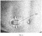
- FIG. 1is an illustration of a typical prior art external sensor apparatus (partially implantable glucose monitor), including typical placement on the abdomen of the host.
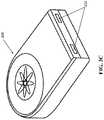
- FIGS. 2A-2Care top, bottom, and side elevation views, respectively, of the exemplary sensor apparatus of FIG. 2 .
- FIG. 3Ais a generalized logical flow diagram illustrating an exemplary embodiment of a method of preparing a sensor apparatus for implantation in accordance with the present disclosure.
- FIG. 3Bis a generalized logical flow diagram illustrating an exemplary embodiment of a method of therapy device or material implantation in accordance with the present disclosure.
- FIG. 3Cis a rear perspective view of an exemplary embodiment of the sensor apparatus, including one or more attachment or anchoring apparatus.
- FIG. 4is perspective cross-sectional view of abdominal “solid tissue” of a typical human being, showing the various components and layers thereof, including fascial layers.
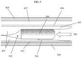
- FIG. 5is side cross-sectional view of an exemplary sensor apparatus implanted within a cavity or pocket formed in the tissue of FIG. 4 , and proximate to the muscular fascia thereof.
- FIG. 6is a generalized logical flow diagram illustrating an exemplary embodiment of a method of surgical implantation utilizing a common implantation site and incision, in accordance with the present disclosure.
- health care providerand “clinician” refer without limitation to providers of health care services such as surgical procedures, diagnosis, monitoring, administration of pharmacological agents, counseling, etc., and include for instance physicians, nurses, medical assistants, technicians, and can even include the user/patient themselves (such as where the patient self-administers, self-monitors, etc.).
- topmerely connote, without limitation, a relative position or geometry of one component to another, and in no way connote an absolute frame of reference or any required orientation.
- a “top” portion of a componentmay actually reside below a “bottom” portion when the component is mounted to another device or object.
- the present disclosureprovides a methodology wherein a fully implantable, biocompatible sensor is disposed within a cavity or pocket formed within a living being (e.g., the frontal portion of a human, more specifically the abdomen, proximate the waistline), such that the sensor remains in a desired orientation and placement after the cavity or pocket is closed, so as to enhance the performance of the sensor (e.g., from an accuracy perspective), and also mitigate the effects of one or more factors potentially deleterious to the operation of the sensor and to the host being (e.g., human).
- a fully implantable, biocompatible sensoris disposed within a cavity or pocket formed within a living being (e.g., the frontal portion of a human, more specifically the abdomen, proximate the waistline), such that the sensor remains in a desired orientation and placement after the cavity or pocket is closed, so as to enhance the performance of the sensor (e.g., from an accuracy perspective), and also mitigate the effects of one or more factors potentially deleterious to the operation of the sensor and to the host being (
- the senorcomprises a somewhat planar biocompatible oxygen-based glucose sensor with multiple (e.g., 8 ) individual sensor elements disposed in a common sensing region on one side of the somewhat planar housing, which is implanted deep within the being's torso subcutaneous tissue proximate the extant abdominal muscle fascia, and optionally oriented so that the sensing region faces away from the being's skin surface (i.e., the plane of the sensor is substantially parallel to the fascia and the epidermis/dermis, with the sensing region facing inward toward the musculature under the fascia).
- the deep placement, orientation, and construction of the exemplary glucose sensoritself cooperate to enhance the performance of the sensor, especially over extended periods of time, with little or no external calibration.
- the foregoing implantation techniquecan advantageously be performed on an outpatient basis by a clinician using only local anesthetic. Recovery time from the procedure is minimal, and current implementations of the sensor apparatus have demonstrated longevity in vivo well in excess of one year.
- the exemplary sensor apparatus 200comprises a somewhat planar housing structure 202 with a sensing region 204 disposed on one side thereof (i.e., a top face 202 a ).
- the exemplary substantially planar shape of the housing 202provides mechanical stability for the sensor apparatus 200 after implantation, thereby helping to preserve the orientation of the apparatus 200 (e.g., with sensing region 204 facing away from the epidermis and toward the proximate fascial layer), resisting rotation around its longitudinal axis 208 , and translation, or rotation about its transverse axis 210 , which might otherwise be caused by e.g., normal patient ambulation or motion, sudden accelerations or decelerations (due to e.g., automobile accidents, operation of high-performance vehicles such as aircraft), or other events or conditions.
- the present disclosurecontemplates sensor apparatus of shapes and/or sizes other than that of the exemplary apparatus 200 , including use of means to maintain the desired orientation and position such as e.g., protruding tabs, “anchoring” the sensor apparatus to surrounding physiological structures such as the fascial layer by means of sutures or the like, and so forth.
- the exemplary sensor apparatus of FIGS. 2-2Cfurther includes a plurality of individual sensor elements 206 with their active surfaces disposed substantially within the sensing region 204 on the top face 202 a of the apparatus housing.
- the eight (8) sensing elements 206are grouped into four pairs, one element of each pair an active sensor, and the other a reference (oxygen) sensor.
- Exemplary implementations of the sensing elements and their supporting circuitry and componentsare described in, inter alia, U.S. Pat. No. 7,248,912, previously incorporated herein.
- the type and operation of the sensor apparatusmay vary; i.e., other types of sensor elements/sensor apparatus, configurations, and signal processing techniques thereof may be used consistent with the various aspects of the present disclosure, including, for example, signal processing techniques based on various combinations of signals from individual elements in the otherwise spatially-defined sensing elements pairs.
- the exemplary sensor apparatus of FIGS. 2-2Calso includes a plurality (three in this instance) of tabs or anchor apparatus 213 disposed substantially peripheral on the apparatus housing.
- these anchor apparatusprovide the implanting surgeon with the opportunity to anchor the apparatus to the anatomy of the living subject, so as to frustrate translation and/or rotation of the sensor apparatus 200 within the subject immediately after implantation but before any body response (e.g., FBR) of the subject has a chance to immobilize (such as via encapsulation) the sensor apparatus.
- the tabs or anchor apparatus 213each comprise a substantially closed loop through which the surgeon may optionally run a dissolvable suture or other such mechanism so as to effect the aforementioned anchoring.
- the closed loopmay be formed e.g., at time of formation of the apparatus housing (e.g., when the housing is formed, molded, forged, or otherwise fashioned), or can be applied thereafter (e.g., via welding or brazing or adhesion of a wire loop or the like to the housing). It will be also appreciated that other configurations, numbers, and/or anchoring mechanisms may be used consistent with the present disclosure, as discussed in greater detail infra.
- one embodiment of the sensor apparatus 200is configured for so-called “deep” implantation within the solid tissue of the subject (e.g., low on the frontal abdominal region), approximately at the level of the deep/muscle fascial layer.
- a fasciais a band or sheet of connective tissue fibers, primarily collagen, disposed beneath the skin, and which functions to attach, stabilize, enclose, and separate muscles and other internal organs. Fasciae are classified according to their distinct layers as in superficial fascia, deep (or muscle) fascia, visceral and parietal fascia, and by their functions and anatomical location.
- fasciaeare made up of fibrous connective tissue containing closely packed bundles of collagen fibers oriented in a wavy pattern substantially parallel to a direction of pull.
- the collagen fibersare produced by the fibroblasts located within the fascia. Fasciae are accordingly flexible structures able to resist great unidirectional tensile forces.
- exemplary disposition of the sensor apparatus 200 at the deep muscular fascial levelprovides several benefits both from the perspective of the user (patient) and the clinician (e.g., surgeon).
- FIG. 3methods of implantation of one or more sensors, and treatment of a living being, are described in detail.
- one exemplary embodiment of a method 300 of implantation of a sensoris disclosed.
- the patiente.g., human being
- the patientis evaluated for: (i) the propriety of use of the implantable sensor (e.g., whether contraindications or other factors make the use of the particular sensor impractical or undesirable); (ii) the best or desired implantation site (which, as discussed elsewhere herein, may or may not be a previously utilized site); and (iii) any other factors which the heath care provider should consider, such as recent other surgeries, recent ingestion of pharmacological agents, and the like.
- the patientis prepared for surgery (whether traditional, laparoscopic, or otherwise).
- preparationmay include for example placement in a surgical environment (e.g., operating or treatment room), disinfecting the surface of the skin at and proximate to the incision site, (such as using Betadine® or similar topical microbicide), administration of pharmaceuticals or other agents for, e.g., anesthetization of the implantation area via local anesthetic, sedation of the patient via various sedating agents, anesthetization of the patient (generally) via a general anesthetic, administration of a prophylactic dose of an antibiotic compound, or the like.
- a surgical environmente.g., operating or treatment room
- sedation of the patientvia various sedating agents
- anesthetization of the patientgenerally
- administration of a prophylactic dose of an antibiotic compoundor the like.
- the incision site(s)may also be marked on the patient at this point.
- the incision site, as well as the desired extent of the pocket to be formedmay be marked to aid the surgeon during the implantation procedure.
- a typical incision length for the sensor apparatus of FIG. 2is on the order of 2.5 cm, although greater and lesser lengths are contemplated by the present disclosure depending on, e.g., the actual size and shape of the implanted device, particular anatomical features or considerations relating to the patient, etc.
- the exemplary sensor apparatus 200 of FIG. 2 hereinis utilized, although as previously discussed, any number of types and/or configurations of sensors may be used consistent with the method 300 .
- the sensorincludes a sensing region 204 disposed on one side of the substantially planar sensor apparatus housing, through which all glucose monitoring is conducted when the sensor apparatus is in vivo.
- the sensor apparatus 200is (i) removed from its packing/shipping container, preserving its sterility after removal and before implantation, (ii) powered up, and (iii) functionally tested so as to assure its operability in certain regards.
- FIG. 3Aillustrates one exemplary methodology for carrying out step 306 of the method 300 .
- the sensor apparatusis first removed from its storage/packing container as noted above (step 315 ).
- the power supply of the apparatusis enabled, such as by inserting or enabling electrical contact with a battery of the apparatus (step 317 ).
- an appropriate external apparatusis utilized.
- the desired configuration for the particular applicatione.g., analyte monitoring selection, wireless interface parameters, sensing/data transmission frequency, etc. for a given patient
- the desired configuration for the particular applicatione.g., analyte monitoring selection, wireless interface parameters, sensing/data transmission frequency, etc. for a given patient
- the exemplary methods of FIGS. 3-3Aillustrate determination of such a configuration
- the present disclosurecontemplates any number of other options, including utilizing a fully pre-programmed sensor apparatus (e.g., with no required or possible user configuration), so as to inter alia, simplify the preparation and implantation of the apparatus, and avoid any potential programming or configuration errors, thereby obviating at least step 319 .
- a communication channelis established between the signal processing/microcontroller architecture of the sensor apparatus and an external device, such as via a wireless “command” channel and protocol.
- a wired (e.g., micro-USB) form factorcan be used along with a serialized bus protocol such as I 2 C, PCIe, etc.
- the wired implementationmay also be constructed such that the physical interface is shielded after completion, internal to the sensor apparatus, or otherwise adapted so as to preclude any ingress of biological matter into the apparatus housing, or conversely any egress of substances from inside the device housing into the surrounding tissue of the patient.
- a properly configured external devicee.g., tablet computer, smartphone, desktop/laptop, flash drive, etc.
- the command channel established in step 321is utilized to configure the sensor apparatus, which may include “flashing” the non-volatile storage within the device with new firmware, configuring one or more user-selectable parameters or options, and the like.
- the configured deviceis then tested to assure proper programming/functionality prior to implantation (although some testing can be accomplished after implantation, as described elsewhere herein).
- the senoris entirely pre-programmed, and is configured to transmit “raw” data signals off-sensor to a receiver (the latter enabling subsequent processing of the raw data signals).
- the sensor apparatuscan optionally be configured with a plurality of capabilities such that a user (e.g., health care provider) can selectively enable or disable features for the current patient/application, thereby in effect customizing the sensor apparatus for the application.
- the sensor apparatusmight include algorithms or signal processing applicable to a particular operational context (e.g., sensing of multiple ones of certain analytes), but which are not appropriate for the current application or patient due to their physiology, age, type of medical condition/diabetes, etc.
- electronic design factorsmay form a basis for the selective configurability, such as e.g., where the sensor apparatus is fitted with multiple wireless air interface types and/or frequency bands, modulation/coding schemes (MCS), etc., all of which may not be needed after implantation.
- MCSmodulation/coding schemes
- certain wireless frequenciese.g., different frequencies within the ISM band
- types of interfacese.g., OFDM versus direct sequence versus narrowband/FDMA
- OFDM versus direct sequence versus narrowband/FDMAmay be more desirable than others, and hence can be selected at time of implantation (subject to regulatory restrictions and requirements), with non-selected options shut off or put to sleep so as to conserve electrical power within the implanted device after implantation, thereby extending its viability in vivo.
- the cliniciancan optionally be given a menu of choices in terms of device configuration from which to select so as to readily optimize the implantation for that given patient, without having to employ a single-function or particular device configuration which may or may not be available to the clinician at that particular surgical location and/or point in time.
- the aforementioned optional configuration of the devicecan be accomplished when the device is in vivo, such as after a trial period.
- the implantation “lifetime” of the sensor apparatusmay be extended (assuming suitable physiological monitoring performance continues) by selectively shutting down or powering off various features, functions or components of the implanted sensor, reprogramming (e.g., download of new firmware which further optimizes operation, etc.), such as via wireless command to the signal processor/microcontroller of the device.
- reprogramminge.g., download of new firmware which further optimizes operation, etc.
- digital processors and wireless baseband processorseach may employ multiple different power planes and “sleep” states which progressively reduce power consumption by the device, depending on the operation demands on the device. If it is determined that, e.g., the frequency of calculations or sensor samplings can be reduced later in the life of a given implementation (such as where the host becomes more familiar with his/her own monitoring, response to certain ingested foods or liquids, etc.), it may be that the “tempo” of operation of the sensor apparatus can be reduced, providing attendant power consumption reduction. For instance, in the context of the exemplary sensor apparatus 200 of FIG.
- the sensor apparatusincludes multiple (4) sets of sensing and reference sensing elements, which are in one implementation adapted to dynamically compensate for e.g., FBR or other so-called “confounding factors” occurring proximate the sensing elements (see, inter alia, U.S. Pat. No. 7,248,912 previously incorporated herein, for a discussion of various such factors), thereby maintaining the accuracy of the device as a whole. Accordingly, as sensing elements or sets thereof become inoperative or unreliable, these elements/sets can be selectively removed from the signal processing logic and deactivated, thereby conserving electrical power, and ostensibly extending the implantation lifetime of the sensor apparatus in that given patient.
- the aforementioned embodiment of the methodologypowers up and checks the functionality of the device (and optionally enables/disables features of the sensor) prior to implantation
- one or more of these procedurescan be performed when the device is in vivo (including after the surgical implantation procedure is complete) if desired.
- the sensoris powered up prior to implantation (since a power circuit or battery malfunction generally cannot be rectified after implantation), yet is not “configured” for operation and tested until it is disposed at its target implantation location deep within the patient's tissue.
- This approachcan advantageously be utilized to, inter alia, both (i) test the sensor in the actual environment which it will be subsequently used (as opposed to merely in “open air” or its sterile shipping/packing environment, each of which may not allow the tests with appropriate sensory input signals as compared to being in vivo with the sensor active sensing region 204 in contact with the patient's tissue) and (ii) obtain representative signal inputs (e.g., from the sensor's sensing array) and outputs (e.g., wireless signals of insufficient strength may be attenuated by the patient's tissue, such attenuation which could not be accurately assessed before the sensor was placed beneath the tissue).
- representative signal inputse.g., from the sensor's sensing array
- outputse.g., wireless signals of insufficient strength may be attenuated by the patient's tissue, such attenuation which could not be accurately assessed before the sensor was placed beneath the tissue.
- Testing performed on the sensor apparatusmay include for example: (i) battery voltage or current checks; (ii) wireless interface checks such as transmission of test data or actual sensed data; (iii) functional command checks, such as where a command is wirelessly transmitted to the device in order to cause the sensor apparatus to perform a function, reconfigure itself, transmit data, etc.
- the patientis surgically incised at the target location (e.g., in the lower abdomen, lateral to the midline, inferior to the umbilicus and superior to the inguinal ligament, and a cavity formed below the skin and extending to the fascia underlying the target location.
- the user's superficial (scarpal) fasciais incised, and the adipose tissue 405 immediately proximate the deeper fascial membrane 402 (i.e., anterior abdominal fascia; see FIGS. 4 and 5 ) is merely separated from the fascial membrane so as to form the desired cavity or pocket 502 , with little or no tissue removal from the patient.
- Such separationis preferably performed using “blunt” techniques (i.e., without cutting per se), to minimize tissue and blood vessel trauma, and also mitigate prospective FBR (which may be exacerbated from cutting versus blunt formation), but may also be performed using an instrument such as a scalpel or surgical scissors if needed or desired for other reasons.
- the surgeonmay remove a small amount of fat cells or tissue in the region in order to accommodate the volume of the sensor apparatus.
- a specialized “pocket forming” surgical toolmay be inserted into the location where the pocket is desired, and then removed to create a suitable pocket.
- the pocketis formed in a substantially vertical direction relative to the (substantially transverse) incision; i.e., the incision is formed low on the patient's abdomen, and the pocket is formed internally with a longitudinal axis thereof pointing roughly towards the patient's head or upper abdomen.
- the target implantation siteis in one implementation chosen to be in the patient's lower abdomen, lateral to the midline, inferior to the umbilicus and superior to the inguinal ligament. While other sites may be used consistent with the present disclosure, this site often has significant advantages associated therewith, both for the implanting surgeon and the patient. Specifically, in obese individuals (or even those merely with a significant amount of fat around their midsection), implantation is typically less traumatic and invasive at the aforementioned target location, since the thickness of the fatty tissue layer in such individuals declines rapidly as a function of proximity to the groin area. Hence, less damage to the patient's tissue and blood vessels occurs when performing implantation in this region.
- such incision locationadvantageously affords the surgeon the ability to implant the sensor apparatus 200 deeply within the patient's abdomen (with all of the attendant benefits thereof), yet with minimal tissue and blood vessel trauma.
- the sensor apparatus 200is implanted within the cavity/pocket in the direction 500 shown, so that the sensing region 204 is both proximate the target fascial layer and oriented in the desired direction (step 310 ).
- the somewhat planar shape of the sensor housing 202helps to maintain the desired sensor orientation and placement; accordingly, the sensor apparatus 200 in the present embodiment of the method 300 is inserted into the cavity 502 with the “flat” sides substantially parallel to the plane of the fascial layer 402 , musculature 404 , superficial fascia 406 , superficial fatty tissue layer 407 , and epidermis 408 , as shown in FIG. 5 .
- the sensor apparatus 200is oriented “round side up”, such that the rounded end 211 (see FIG. 2 ) is inserted into the formed pocket first, thereby aiding in placement with minimal friction and effort.
- the sensor apparatus 200can optionally be affixed or “anchored” to the patient's anatomy so as to, inter alia, preclude the sensor apparatus from moving or dislocating within the patient after implantation (and potentially affecting the operation of the sensor apparatus, such as by changes or failure of the tissue coupling to the sensing elements of the apparatus).
- suturesare used in conjunction with one or more anchor points or tabs 213 formed or disposed on the outer surfaces of the sensor apparatus 200 (see FIGS. 2 and 3C ), such that the sensor apparatus can be sutured to the patient's underlying fascia (e.g., anterior abdominal fascia) or other anatomical feature(s) within or proximate to the formed pocket in the desired location and orientation.
- dissolvable suturesof the type well known in the medical arts are used for such purpose, thereby enabling the sensor apparatus to be secured within the patient until FBR and/or other natural body processes perform this function.
- Use of the dissolvable suturesprovides, inter alia, for easier subsequent explant, since the sutures will have completely dissolved by time of explant (e.g., a year or 18 months from implantation), thereby obviating having to surgically sever and remove them.
- non-dissolvable suturesand/or other anchoring or securing means, such as e.g., (polyester velour) fabric patches or tabs, or the like
- the exemplary sensor apparatus embodimente.g., as shown in FIGS. 2 and 3C
- has three (3) anchor points or tabs 213i.e., one on the front “rounded” portion as shown in FIG. 2 , and two on the rear “squared” portion as shown in FIG. 3C
- anchor points or tabs 213i.e., one on the front “rounded” portion as shown in FIG. 2 , and two on the rear “squared” portion as shown in FIG. 3C
- more or lessmay be used.
- no anchoring meanse.g., allowing the sensor apparatus 200 to “float” within the pocket, the latter which is closed or otherwise configured so as to maintain the desired placement of the sensor apparatus after implantation
- a single anchore.g., a single suture or other means with a single tab 213 on one side or end of the sensor apparatus, so as to at least partly constrain the sensor within the pocket 502
- two (2) or more anchorsideally spaced apart at some distance from each other relative to a characteristic dimension of the sensor apparatus, is considered optimal in many cases so as to frustrate potential “flipping” of the sensor apparatus within the pocket, especially when the pocket is not completely or partly closed off (e.g., before the normal FBR has had an opportunity to establish encapsulation) after implantation; this approach is especially useful in highly active individuals where, by nature of aggressive or jarring physical motion (such as mountain bike riding, playing contact sports, gymnastics, etc.), such undesired movement of the sensor apparatus within the pocket is more likely to occur
- the surgical incision(and optionally the cavity itself) are closed, and post-surgical treatment is applied to the patient.
- the surgical incisionis closed (e.g., via suturing, surgical tape or adhesive, and/or surgical staples) such that scarpal fascia and skin (lower inverted layer and higher layer) are closed, yet the formed pocket 502 is not affirmatively closed off (e.g., sutured), so as to reduce trauma to the patient and ostensibly facilitate later explant.
- the pocket 502may be partly or fully closed off, such as via the aforementioned suturing or other means (e.g., dissolvable surgical tape or patch). Providing such “deep” as well as surface layer wound closures may be helpful in aiding healing and avoiding subsequent compromise of the closed wound, especially in individuals where their particular anatomy and anticipated activity profile might otherwise place undue stress on a single-layer closure.
- a biocompatible shieldwhich may be a rigid ceramic or the like plate or cup-shaped element, or may comprise a compliant material such as silicone rubber, which can be disposed immediately proximate the sensor apparatus or at a tissue layer closer to the epidermis, and which can provide additional ballistic or impingement protection for the sensor apparatus when implanted, such as for patients who engage in contact sports, military, or law enforcement activities, or the like.
- implantation of the sensor apparatus at a greater subcutaneous depthreduces or even eliminates any visible protrusion of the subject's abdomen, thereby making the sensor apparatus effectively invisible to the external observer.
- Selection of the exemplary location near the muscular fascial layer 402advantageously also requires only minimal surgical intervention (e.g., outpatient procedure or the like performed by a general surgeon or similar clinician versus a specialist), since the fascial layer in the exemplary embodiment is not penetrated or incised. Accordingly, only a small incision is necessary (e.g., approximately one to one-and-one-half inches long based on the current implementation of the sensor apparatus), and the entire procedure generally can be completed in less than 15 minutes.
- the degree or level of FBR within the patientmay be directly or indirectly related to the depth of implantation of a given implant (e.g., sensor), such that implantation of such a device at one depth may result in a differing type and/or magnitude of FBR than would occur for the same device implanted at a different depth in the same patient at the same location. Accordingly, the present disclosure contemplates, in one embodiment, use of such relationship as a factor in considering a depth of surgical implantation.
- anecdotal or other dataindicates that FBR is reduced or ameliorated in severity or type as depth of implantation increases
- such informationmay be used in selecting a target location and depth for the sensor apparatus or other implanted device.
- prior art approaches to implantationgenerally consider only “shallow” implantation and/or implantation so as to maintain a prescribed relationship to the patient's external (dermal) layers.
- a more superficial fascial or other layermay in certain cases be used (so as to minimize trauma and recovery time of the subject by not incising or cutting through the superficial fascial layer, while simultaneously providing good sensor performance and the other benefits described herein).
- the present disclosurecontemplates other potential implantation sites, including for example those yet deeper within the patient's anatomy than the exemplary embodiments previously described. For instance, it may be desirable in certain cases to incise through the deeper anterior abdominal fascia referenced above and form the pocket 502 within tissue on the interior side thereof, such as in the case of patients with friable skin structures, or where further protection of the implantable device is desired, or where perfusion of the tissue layers otherwise accessible to the device in the previously described exemplary embodiments is inadequate. In such cases, the preferred orientation of the device would be such that its active face (i.e. the face that required access to perfused tissue) would be adjacent to the fascia layer on which the device was being located. For instance, in one such variant of the implantation method, the sensor apparatus 200 of FIG.
- the radio frequency transceiver/antennamay be configured to transmit RF energy through the same sensor apparatus housing face as the sensor; e.g., with reduced RF power so as to mitigate any possible noise or interference issues with the disposition of the RF transceiver/antenna on or under the same face of the apparatus housing as the sensor elements.
- sensor-face outwardi.e., facing the muscular fascia, but from the interior side
- radio frequency energyis transmitted substantially through the subject toward their back (and thereby maintaining a high level of “noise” isolation between the RF interface and the electronics of the sensor elements).
- the radio frequency transceiver/antennamay be configured to transmit RF energy through the same sensor apparatus housing face as the sensor; e.g., with reduced RF power so as to mitigate any possible noise or interference issues with the disposition of the RF transceiver/antenna on or under the same face of the apparatus housing as the sensor elements.
- the senormay increasingly be appreciably miniaturized, such that successively smaller and smaller incisions are required for implantation of the sensor apparatus over time.
- Laparoscopic implantation, or even a coarse “injection” delivery by trocarare also feasible methods of implantation with appropriate adaptation, such adaptation being well within the skill of an ordinary artisan in the medical or surgical arts when given the present disclosure.
- the “deep” implantation technique of the present disclosurecan also be utilized not only for other types of sensors, but also for apparatus and/or materials other than sensors, including for example devices intended to deliver substances to the body (e.g. implanted drug pumps, drug-eluting solid materials, and encapsulated cell-based implants, etc.), and/or other devices for which implantation may be desired.
- FIG. 3Bshows an exemplary embodiment of a method of implantation of such non-sensor apparatus.
- a method 350 of implantation of e.g., a non-sensor apparatus, such as a therapy apparatus or implantis disclosed.
- the exemplary therapy apparatus or implantis (i) removed from its packing/shipping container, preserving its sterility after removal and before implantation, (ii) powered up (if applicable), and (iii) functionally tested so as to assure its operability in certain regards, as applicable.
- the patientis surgically incised at the target location, and a cavity formed below the skin and extending to the fascia underlying the target location.
- the user's superficial (scarpal) fasciais incised, and the adipose tissue 405 immediately proximate the deeper fascial membrane 402 (i.e., anterior abdominal fascia; see FIGS. 4 and 5 ) is merely separated from the fascial membrane so as to form the desired cavity or pocket 502 , with little or no tissue removal from the patient.
- the surgeonmay remove a small amount of fat cells or tissue in the region in order to accommodate the volume of the therapy apparatus or implant.
- a specialized “pocket forming” surgical toolmay be inserted into the location where the pocket is desired, and then removed to create a suitable pocket.
- the therapy apparatus or implantis implanted within the cavity/pocket per step 360 .
- the therapy apparatus or implantcan optionally be affixed or “anchored” to the patient's anatomy so as to, inter alia, preclude the apparatus or implant from moving or dislocating within the patient after implantation (and potentially affecting the operation thereof).
- step 364 of the method 350the surgical incision (and optionally the cavity itself) are closed, and post-surgical treatment is applied to the patient.
- the present disclosurefurther contemplates that (i) the same implantation site and/or incision used for sensor implantation can be used for successive implantations of sensors and/or other apparatus, (ii) a different implantation site and/or incision can be used for such successive implantations (e.g., access to the same fascial-proximate region may occur via the same or different incision, and access to a different fascial-proximate region may occur via the same or different incision), and (iii) a pre-existing or prior incision from an unrelated procedure (e.g., appendectomy, cesarean section, etc.) may be “repurposed” for implantation, thereby mitigating aesthetic concerns relating to the creation of new scars.
- a healthcare provideris advantageously given a range of options dependent upon the application; e.g., particular patient desires, complications, changes since the last implantation, etc.
- the foregoing “re-use” methodology for implantation 600first identifies the site of the prior implantation and incision at step 602 .
- the patientis prepared for surgery.
- the new sensor to be implantedis unpackaged and readied for implantation, as described supra.
- the prior incisionis re-incised (either wholly or in part), and the extant cavity formed within the tissue re-opened such that the implanted sensor apparatus can be removed (step 610 ).
- the “new” sensor apparatus 200is disposed within the cavity and tested as appropriate, in the desired position and orientation as previously described. Note that depending on the degree of FBR encountered (e.g., contouring of the tissue proximate the sensor elements 206 , etc.), it may be desirable to locate the sensing region 204 in a slightly different location, such as in areas where no contouring or “imprint” has occurred. Conversely, there are situations where it may be desirable to utilize the already contoured portion of the tissue (i.e., mimic placement of the prior sensor apparatus as closely as possible).
- the incision(and optionally the cavity itself as desired) is closed (e.g., sutured or adhered using e.g., an adhesive bandage, surgical staples, or tissue adhesive), with the patient receiving post-surgery treatment and processing for discharge as required.
- closede.g., sutured or adhered using e.g., an adhesive bandage, surgical staples, or tissue adhesive
- new sensor apparatusin the preceding discussion is not limited to a distinct physical device.
- the procedure of FIG. 6may be modified such that the existing (implanted) device is merely provisioned for use again within the same patient (e.g., by changing out the battery, other renewable component, or the like).
- FIG. 7herein is a plot of “proximity index” vs. average sensor O 2 level at 12 weeks (implanted duration), which illustrates exemplary anecdotal data obtained by the Assignee hereof during trials of a generally comparable sensing device and using, inter alfa, ultrasound techniques.
- the data of FIG. 7demonstrates the aforementioned stability of output for extended periods, which is in part afforded by the sensor device's access to the blood supply by virtue of its “deep” placement.
- Each point on the graph of FIG. 7represents the average of the output from the four (4) oxygen reference electrodes on a given implanted device.
Landscapes
- Health & Medical Sciences (AREA)
- Life Sciences & Earth Sciences (AREA)
- Physics & Mathematics (AREA)
- Engineering & Computer Science (AREA)
- Public Health (AREA)
- Biomedical Technology (AREA)
- Heart & Thoracic Surgery (AREA)
- Surgery (AREA)
- Animal Behavior & Ethology (AREA)
- General Health & Medical Sciences (AREA)
- Veterinary Medicine (AREA)
- Medical Informatics (AREA)
- Molecular Biology (AREA)
- Pathology (AREA)
- Biophysics (AREA)
- Optics & Photonics (AREA)
- Computer Networks & Wireless Communication (AREA)
- Emergency Medicine (AREA)
- Nuclear Medicine, Radiotherapy & Molecular Imaging (AREA)
- Vascular Medicine (AREA)
- Anesthesiology (AREA)
- Hematology (AREA)
- Dermatology (AREA)
- Diabetes (AREA)
- Measurement Of The Respiration, Hearing Ability, Form, And Blood Characteristics Of Living Organisms (AREA)
- Physiology (AREA)
- Measuring And Recording Apparatus For Diagnosis (AREA)
- Artificial Intelligence (AREA)
- Computer Vision & Pattern Recognition (AREA)
- Psychiatry (AREA)
- Signal Processing (AREA)
Abstract
Description
Claims (25)
Priority Applications (7)
| Application Number | Priority Date | Filing Date | Title |
|---|---|---|---|
| US14/982,346US10660550B2 (en) | 2015-12-29 | 2015-12-29 | Implantable sensor apparatus and methods |
| CA3009489ACA3009489A1 (en) | 2015-12-29 | 2016-12-28 | Implantable sensor apparatus and methods |
| PCT/US2016/068997WO2017117283A1 (en) | 2015-12-29 | 2016-12-28 | Implantable sensor apparatus and methods |
| AU2016382976AAU2016382976B2 (en) | 2015-12-29 | 2016-12-28 | Implantable sensor apparatus and methods |
| US15/919,052US10736553B2 (en) | 2012-07-26 | 2018-03-12 | Method of manufacturing an analyte detector element |
| AU2020201630AAU2020201630B2 (en) | 2015-12-29 | 2020-03-05 | Implantable sensor apparatus and methods |
| US16/882,182US20200352480A1 (en) | 2015-12-29 | 2020-05-22 | Implantable sensor apparatus and methods |
Applications Claiming Priority (1)
| Application Number | Priority Date | Filing Date | Title |
|---|---|---|---|
| US14/982,346US10660550B2 (en) | 2015-12-29 | 2015-12-29 | Implantable sensor apparatus and methods |
Related Child Applications (1)
| Application Number | Title | Priority Date | Filing Date |
|---|---|---|---|
| US16/882,182ContinuationUS20200352480A1 (en) | 2015-12-29 | 2020-05-22 | Implantable sensor apparatus and methods |
Publications (2)
| Publication Number | Publication Date |
|---|---|
| US20170181674A1 US20170181674A1 (en) | 2017-06-29 |
| US10660550B2true US10660550B2 (en) | 2020-05-26 |
Family
ID=59087623
Family Applications (2)
| Application Number | Title | Priority Date | Filing Date |
|---|---|---|---|
| US14/982,346Active2037-06-30US10660550B2 (en) | 2012-07-26 | 2015-12-29 | Implantable sensor apparatus and methods |
| US16/882,182AbandonedUS20200352480A1 (en) | 2015-12-29 | 2020-05-22 | Implantable sensor apparatus and methods |
Family Applications After (1)
| Application Number | Title | Priority Date | Filing Date |
|---|---|---|---|
| US16/882,182AbandonedUS20200352480A1 (en) | 2015-12-29 | 2020-05-22 | Implantable sensor apparatus and methods |
Country Status (4)
| Country | Link |
|---|---|
| US (2) | US10660550B2 (en) |
| AU (2) | AU2016382976B2 (en) |
| CA (1) | CA3009489A1 (en) |
| WO (1) | WO2017117283A1 (en) |
Cited By (1)
| Publication number | Priority date | Publication date | Assignee | Title |
|---|---|---|---|---|
| US11278668B2 (en) | 2017-12-22 | 2022-03-22 | Glysens Incorporated | Analyte sensor and medicant delivery data evaluation and error reduction apparatus and methods |
Families Citing this family (11)
| Publication number | Priority date | Publication date | Assignee | Title |
|---|---|---|---|---|
| KR20140082642A (en) | 2011-07-26 | 2014-07-02 | 글리젠스 인코포레이티드 | Tissue implantable sensor with hermetically sealed housing |
| US10561353B2 (en) | 2016-06-01 | 2020-02-18 | Glysens Incorporated | Biocompatible implantable sensor apparatus and methods |
| US10638962B2 (en) | 2016-06-29 | 2020-05-05 | Glysens Incorporated | Bio-adaptable implantable sensor apparatus and methods |
| EP4111949B1 (en) | 2017-06-23 | 2023-07-26 | Dexcom, Inc. | Transcutaneous analyte sensors, applicators therefor, and needle hub comprising anti-rotation feature |
| US10638979B2 (en) | 2017-07-10 | 2020-05-05 | Glysens Incorporated | Analyte sensor data evaluation and error reduction apparatus and methods |
| US11331022B2 (en) | 2017-10-24 | 2022-05-17 | Dexcom, Inc. | Pre-connected analyte sensors |
| US20190120785A1 (en) | 2017-10-24 | 2019-04-25 | Dexcom, Inc. | Pre-connected analyte sensors |
| US11255839B2 (en) | 2018-01-04 | 2022-02-22 | Glysens Incorporated | Apparatus and methods for analyte sensor mismatch correction |
| USD926325S1 (en)* | 2018-06-22 | 2021-07-27 | Dexcom, Inc. | Wearable medical monitoring device |
| CN112294301B (en)* | 2019-08-02 | 2024-12-31 | 华广生技股份有限公司 | Physiological signal sensor device |
| EP4460235A4 (en)* | 2022-01-07 | 2025-03-19 | Laxmi Therapeutic Devices, Inc. | CUSTOM CALIBRATION FOR GLUCOSE DETECTION |
Citations (212)
| Publication number | Priority date | Publication date | Assignee | Title |
|---|---|---|---|---|
| US2508523A (en) | 1946-09-11 | 1950-05-23 | Krebs & Co | Device for the protection of the cathodes of electrolytic cells |
| US2563062A (en) | 1947-01-07 | 1951-08-07 | Leeds & Northrup Co | Electrostatic shield for ph electrodes |
| US2805191A (en) | 1952-01-16 | 1957-09-03 | Int Nickel Co | Oxygen analysis of gases |
| US2864750A (en) | 1953-12-01 | 1958-12-16 | Sta Lit Lighter Company | Method and apparatus for water treatment |
| US2998371A (en) | 1958-05-09 | 1961-08-29 | Bruce Dohrmann | Control system |
| US3099575A (en) | 1959-10-20 | 1963-07-30 | Engelhard Ind Inc | Thermocouple |
| US3246235A (en) | 1960-12-30 | 1966-04-12 | Atomic Energy Authority Uk | Apparatus for oxygen analysis of gases |
| US3249250A (en) | 1964-08-04 | 1966-05-03 | Robert G Mckee | Olive dispensing device |
| US3300345A (en) | 1964-09-03 | 1967-01-24 | Jr Ernest H Lyons | Electrolytic cell for producing electricity and method of operating the cell |
| US3308046A (en) | 1963-02-06 | 1967-03-07 | Hazeltine Research Inc | Galvanic action device for scuttling floating objects |
| US3458421A (en) | 1966-07-15 | 1969-07-29 | Ibm | Electrode with integral flow channel |
| US3505195A (en) | 1965-12-29 | 1970-04-07 | Radiometer As | Electrode system for electro-chemical measurements in solutions |
| US3542662A (en) | 1967-04-18 | 1970-11-24 | Du Pont | Enzyme electrode |
| US3616412A (en) | 1968-09-25 | 1971-10-26 | Eastman Kodak Co | Metal recovery unit |
| US3957613A (en) | 1974-11-01 | 1976-05-18 | General Electric Company | Miniature probe having multifunctional electrodes for sensing ions and gases |
| US4036716A (en) | 1974-04-05 | 1977-07-19 | Goteborgs Analyslaboratorium Ab | Method to prevent the formation of incrustations on working electrodes in electrode steam generators or the like and a means for performing the method |
| US4088550A (en) | 1977-05-25 | 1978-05-09 | Diamond Shamrock Corporation | Periodic removal of cathodic deposits by intermittent reversal of the polarity of the cathodes |
| US4240438A (en) | 1978-10-02 | 1980-12-23 | Wisconsin Alumni Research Foundation | Method for monitoring blood glucose levels and elements |
| US4306952A (en) | 1979-05-25 | 1981-12-22 | Magneto-Chemie B.V. | Electrolytic process and apparatus |
| US4340457A (en) | 1980-01-28 | 1982-07-20 | Kater John A R | Ion selective electrodes |
| US4361153A (en) | 1980-05-27 | 1982-11-30 | Cordis Corporation | Implant telemetry system |
| US4366033A (en) | 1978-04-20 | 1982-12-28 | Siemens Aktiengesellschaft | Method for determining the concentration of sugar using an electrocatalytic sugar sensor |
| US4431004A (en) | 1981-10-27 | 1984-02-14 | Bessman Samuel P | Implantable glucose sensor |
| US4458686A (en) | 1979-08-02 | 1984-07-10 | Children's Hospital Medical Center | Cutaneous methods of measuring body substances |
| US4484987A (en) | 1983-05-19 | 1984-11-27 | The Regents Of The University Of California | Method and membrane applicable to implantable sensor |
| US4494950A (en) | 1982-01-19 | 1985-01-22 | The Johns Hopkins University | Plural module medication delivery system |
| US4541431A (en) | 1984-09-20 | 1985-09-17 | Telectronics Pty. Ltd. | Use of telemetry coil to replace magnetically activated reed switch in implantable devices |
| US4550732A (en) | 1984-03-23 | 1985-11-05 | Cordis Corporation | System and process for enabling a predefined function within an implanted device |
| US4553547A (en) | 1982-04-23 | 1985-11-19 | Medtronic, Inc. | Cardiac pacemaker synchronized programming |
| US4571589A (en) | 1982-11-22 | 1986-02-18 | Cordis Corporation | Biomedical implant with high speed, low power two-way telemetry |
| US4637861A (en) | 1985-12-16 | 1987-01-20 | Allied Corporation | Stabilized, lipid membrane-based device and method of analysis |
| US4650547A (en) | 1983-05-19 | 1987-03-17 | The Regents Of The University Of California | Method and membrane applicable to implantable sensor |
| US4671288A (en) | 1985-06-13 | 1987-06-09 | The Regents Of The University Of California | Electrochemical cell sensor for continuous short-term use in tissues and blood |
| US4703756A (en) | 1986-05-06 | 1987-11-03 | The Regents Of The University Of California | Complete glucose monitoring system with an implantable, telemetered sensor module |
| US4746218A (en) | 1984-06-12 | 1988-05-24 | Syconex Corporation | Gas detectors and gas analyzers utilizing spectral absorption |
| US4748562A (en) | 1983-05-04 | 1988-05-31 | Akron City Hospital | Portable circuit and method for performing a time study and analysis of bodily characteristics |
| US4759828A (en) | 1987-04-09 | 1988-07-26 | Nova Biomedical Corporation | Glucose electrode and method of determining glucose |
| US4781798A (en) | 1985-04-19 | 1988-11-01 | The Regents Of The University Of California | Transparent multi-oxygen sensor array and method of using same |
| US4830713A (en) | 1985-08-25 | 1989-05-16 | Orbisphere Laboratories (Inc.) | Regeneration method and device |
| US4890620A (en) | 1985-09-20 | 1990-01-02 | The Regents Of The University Of California | Two-dimensional diffusion glucose substrate sensing electrode |
| US5042902A (en) | 1989-11-16 | 1991-08-27 | Advanced Custom Applications, Inc. | Optical fiber splice and method of use |
| US5046242A (en) | 1982-07-27 | 1991-09-10 | Commonwealth Of Australia | Method of making feedthrough assemblies having hermetic seals between electrical feedthrough elements and ceramic carriers therefor |
| US5077476A (en) | 1990-06-27 | 1991-12-31 | Futrex, Inc. | Instrument for non-invasive measurement of blood glucose |
| US5105811A (en) | 1982-07-27 | 1992-04-21 | Commonwealth Of Australia | Cochlear prosthetic package |
| US5112455A (en) | 1990-07-20 | 1992-05-12 | I Stat Corporation | Method for analytically utilizing microfabricated sensors during wet-up |
| WO1992013271A1 (en) | 1991-01-25 | 1992-08-06 | Markwell Medical Institute, Inc. | Implantable biological fluid measuring device |
| US5150516A (en) | 1989-09-28 | 1992-09-29 | Societa' Cavi Pirelli S.P.A. | Process for making detachable connecting means for ribbon optical fiber cables and the connecting means obtained thereby |
| US5165406A (en) | 1990-09-13 | 1992-11-24 | Via Medical Corporation | Electrochemical sensor apparatus and method |
| US5189717A (en) | 1988-04-18 | 1993-02-23 | Minnesota Mining And Manufacturing Company | Optical fiber splice |
| US5264103A (en) | 1991-10-18 | 1993-11-23 | Matsushita Electric Industrial Co., Ltd. | Biosensor and a method for measuring a concentration of a substrate in a sample |
| US5272283A (en) | 1982-07-27 | 1993-12-21 | Commonwealth Of Australia | Feedthrough assembly for cochlear prosthetic package |
| US5273203A (en) | 1989-12-21 | 1993-12-28 | General Electric Company | Ceramic-to-conducting-lead hermetic seal |
| US5283104A (en) | 1991-03-20 | 1994-02-01 | International Business Machines Corporation | Via paste compositions and use thereof to form conductive vias in circuitized ceramic substrates |
| US5283204A (en) | 1992-04-15 | 1994-02-01 | Micron Semiconductor, Inc. | Method of forming passivation oxidation for improving cell leakage and cell area |
| US5284140A (en) | 1992-02-11 | 1994-02-08 | Eli Lilly And Company | Acrylic copolymer membranes for biosensors |
| US5322063A (en) | 1991-10-04 | 1994-06-21 | Eli Lilly And Company | Hydrophilic polyurethane membranes for electrochemical glucose sensors |
| US5395504A (en) | 1993-02-04 | 1995-03-07 | Asulab S.A. | Electrochemical measuring system with multizone sensors |
| US5431160A (en) | 1989-07-19 | 1995-07-11 | University Of New Mexico | Miniature implantable refillable glucose sensor and material therefor |
| US5487855A (en) | 1994-09-16 | 1996-01-30 | Nalco Chemical Company | Polymeric binders for enhancing green strength of pressed ceramics |
| US5497772A (en) | 1993-11-19 | 1996-03-12 | Alfred E. Mann Foundation For Scientific Research | Glucose monitoring system |
| US5560098A (en) | 1992-07-22 | 1996-10-01 | Central Research Laboratories Limited | Method of making an electrical connection to thick film tracks |
| US5692299A (en) | 1993-04-19 | 1997-12-02 | Raychem Corporation | Fiber optic splice closure and associated methods |
| US5695623A (en) | 1989-07-07 | 1997-12-09 | Disetronic Licensing Ag | Glucose measuring device |
| US5711861A (en) | 1995-11-22 | 1998-01-27 | Ward; W. Kenneth | Device for monitoring changes in analyte concentration |
| US5727283A (en) | 1994-05-28 | 1998-03-17 | Black & Decker Inc. | Collection apparatus |
| US5741330A (en) | 1990-10-31 | 1998-04-21 | Baxter International, Inc. | Close vascularization implant material |
| US5750926A (en) | 1995-08-16 | 1998-05-12 | Alfred E. Mann Foundation For Scientific Research | Hermetically sealed electrical feedthrough for use with implantable electronic devices |
| US5776324A (en) | 1996-05-17 | 1998-07-07 | Encelle, Inc. | Electrochemical biosensors |
| US5777060A (en) | 1995-03-27 | 1998-07-07 | Minimed, Inc. | Silicon-containing biocompatible membranes |
| US5782755A (en) | 1993-11-15 | 1998-07-21 | Non-Invasive Technology, Inc. | Monitoring one or more solutes in a biological system using optical techniques |
| US5782891A (en) | 1994-06-16 | 1998-07-21 | Medtronic, Inc. | Implantable ceramic enclosure for pacing, neurological, and other medical applications in the human body |
| US5791344A (en) | 1993-11-19 | 1998-08-11 | Alfred E. Mann Foundation For Scientific Research | Patient monitoring system |
| US5804048A (en) | 1996-08-15 | 1998-09-08 | Via Medical Corporation | Electrode assembly for assaying glucose |
| US5821011A (en) | 1989-10-11 | 1998-10-13 | Medtronic, Inc. | Body implanted device with electrical feedthrough |
| US5842983A (en) | 1995-08-18 | 1998-12-01 | Fresenius Ag | Biosensor |
| US5855995A (en) | 1997-02-21 | 1999-01-05 | Medtronic, Inc. | Ceramic substrate for implantable medical devices |
| US5864088A (en) | 1994-01-20 | 1999-01-26 | Tokin Corporation | Electronic device having the electromagnetic interference suppressing body |
| US5887240A (en) | 1998-05-11 | 1999-03-23 | General Motors Corporation | Method of manufacturing a platinum electrode |
| US5932175A (en) | 1996-09-25 | 1999-08-03 | Via Medical Corporation | Sensor apparatus for use in measuring a parameter of a fluid sample |
| US5942842A (en) | 1992-02-07 | 1999-08-24 | Fogle, Jr.; Homer William | Hermetically-sealed electrically-absorptive low-pass radio frequency filters and electromagnetically lossy ceramic materials for said filters |
| US5964993A (en) | 1996-12-19 | 1999-10-12 | Implanted Biosystems Inc. | Glucose sensor |
| JPH11295556A (en) | 1998-04-06 | 1999-10-29 | Fujikura Ltd | Optical fiber splicer |
| US5985129A (en) | 1989-12-14 | 1999-11-16 | The Regents Of The University Of California | Method for increasing the service life of an implantable sensor |
| US6001067A (en) | 1997-03-04 | 1999-12-14 | Shults; Mark C. | Device and method for determining analyte levels |
| US6027479A (en) | 1998-02-27 | 2000-02-22 | Via Medical Corporation | Medical apparatus incorporating pressurized supply of storage liquid |
| JP2000121863A (en) | 1998-10-20 | 2000-04-28 | Sumitomo Electric Ind Ltd | Optical fiber core with mechanical splice, optical fiber core connector and optical connector |
| US6081736A (en) | 1997-10-20 | 2000-06-27 | Alfred E. Mann Foundation | Implantable enzyme-based monitoring systems adapted for long term use |
| US6096066A (en) | 1998-09-11 | 2000-08-01 | Light Sciences Limited Partnership | Conformal patch for administering light therapy to subcutaneous tumors |
| US6107083A (en) | 1998-08-21 | 2000-08-22 | Bayer Corporation | Optical oxidative enzyme-based sensors |
| US6119208A (en) | 1997-04-18 | 2000-09-12 | Storage Technology Corporation | MVS device backup system for a data processor using a data storage subsystem snapshot copy capability |
| US6193421B1 (en) | 1996-10-09 | 2001-02-27 | Sumitomo Electric Industries, Ltd | Optical connector and a method of attaching the same |
| US6200772B1 (en) | 1997-08-23 | 2001-03-13 | Sensalyse Holdings Limited | Modified polyurethane membrane sensors and analytical methods |
| US6221513B1 (en) | 1998-05-12 | 2001-04-24 | Pacific Coast Technologies, Inc. | Methods for hermetically sealing ceramic to metallic surfaces and assemblies incorporating such seals |
| US20020026108A1 (en) | 1998-08-26 | 2002-02-28 | Colvin Arthur E. | Optical-based sensing devices |
| US6403944B1 (en) | 1997-03-07 | 2002-06-11 | Abbott Laboratories | System for measuring a biological parameter by means of photoacoustic interaction |
| US20020123087A1 (en) | 2000-12-29 | 2002-09-05 | Vachon David J. | Hydrophilic polymeric material for coating biosensors |
| US20020156355A1 (en) | 2001-02-15 | 2002-10-24 | Gough David A. | Membrane and electrode structure for implantable sensor |
| US20020161286A1 (en) | 2001-03-16 | 2002-10-31 | Martin Gerber | Subcutaneous analyte sensor |
| US20020193671A1 (en) | 2000-08-21 | 2002-12-19 | Ciurczak Emil W. | Near infrared blood glucose monitoring system |
| US6516808B2 (en) | 1997-09-12 | 2003-02-11 | Alfred E. Mann Foundation For Scientific Research | Hermetic feedthrough for an implantable device |
| US20030048621A1 (en) | 2001-09-10 | 2003-03-13 | Cardiac Pacemakers, Inc. | Multi-folded printed wiring construction for an implantable medical device |
| US20030049166A1 (en) | 2001-09-07 | 2003-03-13 | Shaun Pendo | Sensor substrate and method of fabricating same |
| US20030053784A1 (en) | 2001-09-19 | 2003-03-20 | Labrake Dwayne L. | Optical and optoelectronic articles |
| US6551252B2 (en) | 2000-04-17 | 2003-04-22 | Vivometrics, Inc. | Systems and methods for ambulatory monitoring of physiological signs |
| US6558321B1 (en) | 1997-03-04 | 2003-05-06 | Dexcom, Inc. | Systems and methods for remote monitoring and modulation of medical devices |
| US20030126593A1 (en) | 2002-11-04 | 2003-07-03 | Mault James R. | Interactive physiological monitoring system |
| US20030179167A1 (en) | 2002-03-25 | 2003-09-25 | Kolluri Omprakash S. | Fluid exchange system for displays |
| US20030181794A1 (en) | 2002-01-29 | 2003-09-25 | Rini Christopher J. | Implantable sensor housing, sensor unit and methods for forming and using the same |
| US20030187338A1 (en) | 1998-04-30 | 2003-10-02 | Therasense, Inc. | Analyte monitoring device and methods of use |
| US20030217966A1 (en) | 2002-05-22 | 2003-11-27 | Dexcom, Inc. | Techniques to improve polyurethane membranes for implantable glucose sensors |
| US20030228681A1 (en) | 2002-04-05 | 2003-12-11 | Powerzyme, Inc. | Analyte sensor |
| US20040012935A1 (en) | 2002-07-16 | 2004-01-22 | Matsushita Electric Industrial Co., Ltd. | Printed wiring board |
| US20040011671A1 (en) | 1997-03-04 | 2004-01-22 | Dexcom, Inc. | Device and method for determining analyte levels |
| US20040057043A1 (en) | 2002-08-29 | 2004-03-25 | Newman John W. | System and process for detecting leaks in sealed articles |
| US20040064133A1 (en) | 2002-09-27 | 2004-04-01 | Medtronic-Minimed | Implantable sensor method and system |
| US6741877B1 (en) | 1997-03-04 | 2004-05-25 | Dexcom, Inc. | Device and method for determining analyte levels |
| US20040158194A1 (en) | 2003-02-06 | 2004-08-12 | Wolff Andy And Beiski Ben Z. | Oral devices and methods for controlled drug release |
| US20040167080A1 (en) | 1995-03-15 | 2004-08-26 | Dodge Jeffrey A. | Glucopyranoside benzothiophenes |
| US20040190111A1 (en) | 2003-03-24 | 2004-09-30 | Memphis Eye & Cataract Associates Ambulatory Surgery Center (Dba Meca Laser And Surgery Center | Digital micromirror device having a window transparent to ultraviolet (UV) light |
| US20040199059A1 (en)* | 2003-04-04 | 2004-10-07 | Dexcom, Inc. | Optimized sensor geometry for an implantable glucose sensor |
| US6809607B2 (en) | 2001-03-19 | 2004-10-26 | Samsung Electronics Co., Ltd. | Circuit and method for compensating for non-linear distortion |
| US6812404B1 (en) | 2003-10-14 | 2004-11-02 | Medtronic, Inc. | Feedthrough device having electrochemical corrosion protection |
| US20040220459A1 (en) | 2003-05-02 | 2004-11-04 | Schlegel Robert P. | Zero corrected optical blood analyte detector |
| EP0852414B1 (en) | 1997-01-07 | 2004-11-24 | Berg Electronics Manufacturing B.V. | Connector with integrated PCB assembly |
| US6832114B1 (en) | 2000-11-21 | 2004-12-14 | Advanced Bionics Corporation | Systems and methods for modulation of pancreatic endocrine secretion and treatment of diabetes |
| US20050027175A1 (en) | 2003-07-31 | 2005-02-03 | Zhongping Yang | Implantable biosensor |
| US20050031689A1 (en) | 2003-05-21 | 2005-02-10 | Dexcom, Inc. | Biointerface membranes incorporating bioactive agents |
| US20050033132A1 (en) | 1997-03-04 | 2005-02-10 | Shults Mark C. | Analyte measuring device |
| CN1592570A (en) | 2003-09-05 | 2005-03-09 | 日本电气株式会社 | Compact radio equipment and method of mounting the same |
| US20050059871A1 (en) | 2002-10-31 | 2005-03-17 | Regents Of The University Of California | Tissue implantable sensors for measurement of blood solutes |
| US20050154271A1 (en) | 2003-11-19 | 2005-07-14 | Andrew Rasdal | Integrated receiver for continuous analyte sensor |
| US6931268B1 (en) | 1995-06-07 | 2005-08-16 | Masimo Laboratories, Inc. | Active pulse blood constituent monitoring |
| US20050196322A1 (en) | 2004-01-29 | 2005-09-08 | Bryan Truex | Apparatus, system, and method of detecting an analyte utilizing pyroelectric technology |
| US20050245799A1 (en)* | 2004-05-03 | 2005-11-03 | Dexcom, Inc. | Implantable analyte sensor |
| US20050245971A1 (en) | 2004-04-28 | 2005-11-03 | Brockway Brian P | Implantable medical devices and related methods |
| JP2005308982A (en) | 2004-04-20 | 2005-11-04 | Matsushita Electric Works Ltd | Optical fiber holding member and optical connector using the same |
| US20050251083A1 (en) | 2004-02-12 | 2005-11-10 | Victoria Carr-Brendel | Biointerface with macro-and micro-architecture |
| US20050272989A1 (en) | 2004-06-04 | 2005-12-08 | Medtronic Minimed, Inc. | Analyte sensors and methods for making and using them |
| US20060085137A1 (en) | 2002-03-22 | 2006-04-20 | Miroslaw Bartkowiak | Micropressors, devices and methods for use in analyte monitoring systems |
| US7079881B2 (en) | 1997-09-12 | 2006-07-18 | Alfred E. Mann Foundation For Scientific Research | Substrate sensor |
| US20060195029A1 (en) | 2004-07-13 | 2006-08-31 | Shults Mark C | Low oxygen in vivo analyte sensor |
| US20060257996A1 (en) | 2005-04-15 | 2006-11-16 | Simpson Peter C | Analyte sensing biointerface |
| US20060257995A1 (en) | 2005-04-15 | 2006-11-16 | Peter Simpson | Analyte sensing biointerface |
| US7140787B2 (en) | 2002-08-21 | 2006-11-28 | 3M Innovative Properties Company | Optical fiber mechanical splice with strain relief mechanism |
| US7146203B2 (en) | 2003-12-18 | 2006-12-05 | Elliot Botvinick | Implantable biosensor and methods of use thereof |
| US7189341B2 (en) | 2003-08-15 | 2007-03-13 | Animas Technologies, Llc | Electrochemical sensor ink compositions, electrodes, and uses thereof |
| JP2007121886A (en) | 2005-10-31 | 2007-05-17 | Sumitomo Electric Ind Ltd | Optical fiber connection jig |
| US20070151868A1 (en) | 2005-11-12 | 2007-07-05 | Arnulf Staib | Implantable electrode system, method and apparatus for measuring an analyte concentration in a human or animal body |
| CN101006374A (en) | 2004-07-16 | 2007-07-25 | 3M创新有限公司 | Optical connectors and fiber optic connection systems |
| WO2008013881A2 (en) | 2006-07-26 | 2008-01-31 | Medtronic Minimed, Inc. | Methods and materials for stabilizing analyte sensors |
| US20080033269A1 (en) | 2004-12-08 | 2008-02-07 | San Medi Tech (Huzhou) Co., Ltd. | Catheter-free implantable needle biosensor |
| US20080039702A1 (en) | 2006-08-09 | 2008-02-14 | Abbott Diabetes Care, Inc. | Method and System for Providing Calibration of an Analyte Sensor in an Analyte Monitoring System |
| US20080197024A1 (en) | 2003-12-05 | 2008-08-21 | Dexcom, Inc. | Analyte sensor |
| US20080200791A1 (en) | 2006-10-04 | 2008-08-21 | Dexcom, Inc. | Analyte sensor |
| US7460898B2 (en) | 2003-12-05 | 2008-12-02 | Dexcom, Inc. | Dual electrode system for a continuous analyte sensor |
| US7467003B2 (en) | 2003-12-05 | 2008-12-16 | Dexcom, Inc. | Dual electrode system for a continuous analyte sensor |
| US20080317276A1 (en) | 2007-06-20 | 2008-12-25 | Sonion Horsens A/S | High efficient miniature electro-acoustic transducer with reduced dimensions |
| US7471972B2 (en) | 2001-07-27 | 2008-12-30 | Dexcom, Inc. | Sensor head for use with implantable devices |
| US7480988B2 (en) | 2001-03-30 | 2009-01-27 | Second Sight Medical Products, Inc. | Method and apparatus for providing hermetic electrical feedthrough |
| US7497827B2 (en) | 2004-07-13 | 2009-03-03 | Dexcom, Inc. | Transcutaneous analyte sensor |
| CN201207090Y (en) | 2008-04-24 | 2009-03-11 | 深圳日海通讯技术股份有限公司 | Mechanical connecting piece for optical fiber |
| US7514791B2 (en) | 2002-09-27 | 2009-04-07 | Medtronic Minimed, Inc. | High reliability multilayer circuit substrates |
| US7525298B2 (en) | 2001-10-23 | 2009-04-28 | Medtronic Minimed, Inc. | Implantable sensor electrodes and electronic circuitry |
| US20090281399A1 (en) | 2007-08-31 | 2009-11-12 | Keel Allen J | Standalone systemic arterial blood pressure monitoring device |
| US20100041971A1 (en) | 2004-05-03 | 2010-02-18 | Dexcom, Inc. | Implantable analyte sensor |
| US20100145317A1 (en) | 2007-04-19 | 2010-06-10 | Morris Laster | Device system and method for monitoring and controlling blood analyte levels |
| US20100149042A1 (en) | 2008-12-12 | 2010-06-17 | Microchips, Inc. | Wireless communication with a medical implant |
| US7761130B2 (en) | 2003-07-25 | 2010-07-20 | Dexcom, Inc. | Dual electrode system for a continuous analyte sensor |
| US7857760B2 (en) | 2004-07-13 | 2010-12-28 | Dexcom, Inc. | Analyte sensor |
| US7871456B2 (en) | 2006-08-10 | 2011-01-18 | The Regents Of The University Of California | Membranes with controlled permeability to polar and apolar molecules in solution and methods of making same |
| WO2011018407A1 (en) | 2009-08-08 | 2011-02-17 | Sanofi-Aventis Deutschland Gmbh | Implantable sensor device and medical delivery device connectable to such a sensor device |
| US7894870B1 (en) | 2004-02-13 | 2011-02-22 | Glysens, Incorporated | Hermetic implantable sensor |
| WO2011120014A1 (en) | 2010-03-25 | 2011-09-29 | Olive Medical Corporation | System and method for providing a single use imaging device for medical applications |
| US8133178B2 (en) | 2006-02-22 | 2012-03-13 | Dexcom, Inc. | Analyte sensor |
| US20120262298A1 (en) | 2011-04-15 | 2012-10-18 | Dexcom, Inc. | Advanced analyte sensor calibration and error detection |
| US20120283960A1 (en) | 2009-01-29 | 2012-11-08 | Abbott Diabetes Care Inc. | Method and Device for Providing Offset Model Based Calibration for Analyte Sensor |
| US20120323100A1 (en) | 2003-08-22 | 2012-12-20 | Dexcom, Inc. | Systems and methods for replacing signal artifacts in a glucose sensor data stream |
| US20130016573A1 (en) | 2011-07-11 | 2013-01-17 | Lsi Corporation | Memory device with trimmable power gating capabilities |
| US8357107B2 (en) | 2004-04-16 | 2013-01-22 | Becton, Dickinson And Company | Blood glucose meter having integral lancet device and test strip storage vial for single handed use and methods for using same |
| WO2013016573A1 (en) | 2011-07-26 | 2013-01-31 | Glysens Incorporated | Tissue implantable sensor with hermetically sealed housing |
| US20130172692A1 (en) | 2010-07-13 | 2013-07-04 | Philosys Co., Ltd. | Blood glucose measurement method using blood glucose meter having step counter function |
| US20130178727A1 (en) | 2007-10-23 | 2013-07-11 | Abbott Diabetes Care Inc. | Analyte sensor with lag compensation |
| US20140046148A1 (en) | 2009-07-02 | 2014-02-13 | Dexcom, Inc. | Analyte sensor |
| WO2014035672A2 (en) | 2012-08-30 | 2014-03-06 | Medtronic Minimed, Inc. | Safeguarding techniques for a closed-loop insulin infusion system |
| US8690820B2 (en) | 2009-10-06 | 2014-04-08 | Illinois Institute Of Technology | Automatic insulin pumps using recursive multivariable models and adaptive control algorithms |
| US8763245B1 (en) | 2006-06-30 | 2014-07-01 | Glysens, Inc., a California Corporation | Hermetic feedthrough assembly for ceramic body |
| US20140323960A1 (en) | 2002-12-31 | 2014-10-30 | Abbott Diabetes Care Inc. | Method and System for Providing Data Communication in Continuous Glucose Monitoring and Management System |
| US20140350652A1 (en)* | 2011-09-28 | 2014-11-27 | Wanijinarjo Suwito | Modular biomedical implants |
| US9002711B2 (en) | 2009-03-25 | 2015-04-07 | Kabushiki Kaisha Toshiba | Speech synthesis apparatus and method |
| US20150163602A1 (en) | 2013-12-06 | 2015-06-11 | Oticon A/S | Hearing aid device for hands free communication |
| US9119528B2 (en) | 2012-10-30 | 2015-09-01 | Dexcom, Inc. | Systems and methods for providing sensitive and specific alarms |
| US20150289823A1 (en) | 2014-04-10 | 2015-10-15 | Dexcom, Inc. | Glycemic urgency assessment and alerts interface |
| US20150335285A1 (en) | 2012-10-31 | 2015-11-26 | The Board Of Trustees Of The Leland Stanford Junior University | Wireless implantable sensing devices |
| US20160022180A1 (en) | 2014-07-24 | 2016-01-28 | Thomas Jefferson University | Long-term implantable monitoring system & methods of use |
| US20160073964A1 (en) | 2013-02-20 | 2016-03-17 | Università Degli Studi Di Padova Area Trasfermiento Di Tecnologia | Retrospective retrofitting method to generate a continuous glucose concentration profile by exploiting continuous glucose monitoring sensor data and blood glucose measurements |
| US9325060B2 (en) | 2014-02-12 | 2016-04-26 | Pulse Finland Oy | Methods and apparatus for conductive element deposition and formation |
| US20160134980A1 (en) | 2006-05-30 | 2016-05-12 | Sonitus Medical, Inc. | Methods and apparatus for processing audio signals |
| US9362776B2 (en) | 2012-11-27 | 2016-06-07 | Qualcomm Incorporated | Wireless charging systems and methods |
| US20160163174A1 (en) | 2014-03-18 | 2016-06-09 | Jack Ke Zhang | Techniques for emergency detection and emergency alert messaging |
| US20160235300A1 (en) | 2005-02-08 | 2016-08-18 | Abbott Diabetes Care Inc. | Analyte Meter Including an RFID Reader |
| US9444027B2 (en) | 2011-10-04 | 2016-09-13 | Infineon Technologies Ag | Thermoelectrical device and method for manufacturing same |
| US9451908B2 (en) | 2006-10-04 | 2016-09-27 | Dexcom, Inc. | Analyte sensor |
| US20160317744A1 (en) | 2008-09-12 | 2016-11-03 | Peter Rule | Fluid component analysis system and method for glucose monitoring and control |
| US20170173262A1 (en) | 2017-03-01 | 2017-06-22 | François Paul VELTZ | Medical systems, devices and methods |
| US20170181630A1 (en) | 2015-12-28 | 2017-06-29 | Dexcom, Inc. | Systems and methods for remote and host monitoring communications |
| US20170181628A1 (en) | 2015-12-28 | 2017-06-29 | Dexcom, Inc. | Intelligent wireless communications for continuous analyte monitoring |
| US20170325725A1 (en) | 2016-05-13 | 2017-11-16 | Percusense, LLC | Vivo sensing and infusion devices |
| US20170347932A1 (en) | 2016-06-01 | 2017-12-07 | Glysens Incorporated | Biocompatible implantable sensor apparatus and methods |
| US20170357776A1 (en) | 2014-10-03 | 2017-12-14 | Jeff Baker | Medicament training device and system |
| US20180000395A1 (en) | 2016-06-29 | 2018-01-04 | Glysens Incorporated | Bio-adaptable implantable sensor apparatus and methods |
| US20180140239A1 (en) | 2016-11-22 | 2018-05-24 | Glysens Incorporated | Heterogeneous analyte sensor apparatus and methods |
| US20180153450A1 (en) | 2016-12-02 | 2018-06-07 | Glysens Incorporated | Analyte sensor receiver apparatus and methods |
Family Cites Families (4)
| Publication number | Priority date | Publication date | Assignee | Title |
|---|---|---|---|---|
| US8688188B2 (en)* | 1998-04-30 | 2014-04-01 | Abbott Diabetes Care Inc. | Analyte monitoring device and methods of use |
| US20140121989A1 (en)* | 2003-08-22 | 2014-05-01 | Dexcom, Inc. | Systems and methods for processing analyte sensor data |
| EP2537032A1 (en)* | 2010-02-19 | 2012-12-26 | Lightship Medical Limited | Subcutaneous glucose sensor |
| US9241631B2 (en)* | 2010-10-27 | 2016-01-26 | Dexcom, Inc. | Continuous analyte monitor data recording device operable in a blinded mode |
- 2015
- 2015-12-29USUS14/982,346patent/US10660550B2/enactiveActive
- 2016
- 2016-12-28CACA3009489Apatent/CA3009489A1/ennot_activeAbandoned
- 2016-12-28AUAU2016382976Apatent/AU2016382976B2/ennot_activeCeased
- 2016-12-28WOPCT/US2016/068997patent/WO2017117283A1/ennot_activeCeased
- 2020
- 2020-03-05AUAU2020201630Apatent/AU2020201630B2/ennot_activeCeased
- 2020-05-22USUS16/882,182patent/US20200352480A1/ennot_activeAbandoned
Patent Citations (251)
| Publication number | Priority date | Publication date | Assignee | Title |
|---|---|---|---|---|
| US2508523A (en) | 1946-09-11 | 1950-05-23 | Krebs & Co | Device for the protection of the cathodes of electrolytic cells |
| US2563062A (en) | 1947-01-07 | 1951-08-07 | Leeds & Northrup Co | Electrostatic shield for ph electrodes |
| US2805191A (en) | 1952-01-16 | 1957-09-03 | Int Nickel Co | Oxygen analysis of gases |
| US2864750A (en) | 1953-12-01 | 1958-12-16 | Sta Lit Lighter Company | Method and apparatus for water treatment |
| US2998371A (en) | 1958-05-09 | 1961-08-29 | Bruce Dohrmann | Control system |
| US3099575A (en) | 1959-10-20 | 1963-07-30 | Engelhard Ind Inc | Thermocouple |
| US3246235A (en) | 1960-12-30 | 1966-04-12 | Atomic Energy Authority Uk | Apparatus for oxygen analysis of gases |
| US3308046A (en) | 1963-02-06 | 1967-03-07 | Hazeltine Research Inc | Galvanic action device for scuttling floating objects |
| US3249250A (en) | 1964-08-04 | 1966-05-03 | Robert G Mckee | Olive dispensing device |
| US3300345A (en) | 1964-09-03 | 1967-01-24 | Jr Ernest H Lyons | Electrolytic cell for producing electricity and method of operating the cell |
| US3505195A (en) | 1965-12-29 | 1970-04-07 | Radiometer As | Electrode system for electro-chemical measurements in solutions |
| US3458421A (en) | 1966-07-15 | 1969-07-29 | Ibm | Electrode with integral flow channel |
| US3542662A (en) | 1967-04-18 | 1970-11-24 | Du Pont | Enzyme electrode |
| US3616412A (en) | 1968-09-25 | 1971-10-26 | Eastman Kodak Co | Metal recovery unit |
| US4036716A (en) | 1974-04-05 | 1977-07-19 | Goteborgs Analyslaboratorium Ab | Method to prevent the formation of incrustations on working electrodes in electrode steam generators or the like and a means for performing the method |
| US3957613A (en) | 1974-11-01 | 1976-05-18 | General Electric Company | Miniature probe having multifunctional electrodes for sensing ions and gases |
| US4088550A (en) | 1977-05-25 | 1978-05-09 | Diamond Shamrock Corporation | Periodic removal of cathodic deposits by intermittent reversal of the polarity of the cathodes |
| US4366033A (en) | 1978-04-20 | 1982-12-28 | Siemens Aktiengesellschaft | Method for determining the concentration of sugar using an electrocatalytic sugar sensor |
| US4240438A (en) | 1978-10-02 | 1980-12-23 | Wisconsin Alumni Research Foundation | Method for monitoring blood glucose levels and elements |
| US4306952A (en) | 1979-05-25 | 1981-12-22 | Magneto-Chemie B.V. | Electrolytic process and apparatus |
| US4458686A (en) | 1979-08-02 | 1984-07-10 | Children's Hospital Medical Center | Cutaneous methods of measuring body substances |
| US4340457A (en) | 1980-01-28 | 1982-07-20 | Kater John A R | Ion selective electrodes |
| US4361153A (en) | 1980-05-27 | 1982-11-30 | Cordis Corporation | Implant telemetry system |
| US4431004A (en) | 1981-10-27 | 1984-02-14 | Bessman Samuel P | Implantable glucose sensor |
| US4494950A (en) | 1982-01-19 | 1985-01-22 | The Johns Hopkins University | Plural module medication delivery system |
| US4553547A (en) | 1982-04-23 | 1985-11-19 | Medtronic, Inc. | Cardiac pacemaker synchronized programming |
| US5272283A (en) | 1982-07-27 | 1993-12-21 | Commonwealth Of Australia | Feedthrough assembly for cochlear prosthetic package |
| US5105811A (en) | 1982-07-27 | 1992-04-21 | Commonwealth Of Australia | Cochlear prosthetic package |
| US5046242A (en) | 1982-07-27 | 1991-09-10 | Commonwealth Of Australia | Method of making feedthrough assemblies having hermetic seals between electrical feedthrough elements and ceramic carriers therefor |
| US4571589A (en) | 1982-11-22 | 1986-02-18 | Cordis Corporation | Biomedical implant with high speed, low power two-way telemetry |
| US4748562A (en) | 1983-05-04 | 1988-05-31 | Akron City Hospital | Portable circuit and method for performing a time study and analysis of bodily characteristics |
| US4484987A (en) | 1983-05-19 | 1984-11-27 | The Regents Of The University Of California | Method and membrane applicable to implantable sensor |
| US4650547A (en) | 1983-05-19 | 1987-03-17 | The Regents Of The University Of California | Method and membrane applicable to implantable sensor |
| US4550732A (en) | 1984-03-23 | 1985-11-05 | Cordis Corporation | System and process for enabling a predefined function within an implanted device |
| US4746218A (en) | 1984-06-12 | 1988-05-24 | Syconex Corporation | Gas detectors and gas analyzers utilizing spectral absorption |
| US4541431A (en) | 1984-09-20 | 1985-09-17 | Telectronics Pty. Ltd. | Use of telemetry coil to replace magnetically activated reed switch in implantable devices |
| US4781798A (en) | 1985-04-19 | 1988-11-01 | The Regents Of The University Of California | Transparent multi-oxygen sensor array and method of using same |
| US4671288A (en) | 1985-06-13 | 1987-06-09 | The Regents Of The University Of California | Electrochemical cell sensor for continuous short-term use in tissues and blood |
| US4830713A (en) | 1985-08-25 | 1989-05-16 | Orbisphere Laboratories (Inc.) | Regeneration method and device |
| US4890620A (en) | 1985-09-20 | 1990-01-02 | The Regents Of The University Of California | Two-dimensional diffusion glucose substrate sensing electrode |
| US4637861A (en) | 1985-12-16 | 1987-01-20 | Allied Corporation | Stabilized, lipid membrane-based device and method of analysis |
| US4703756A (en) | 1986-05-06 | 1987-11-03 | The Regents Of The University Of California | Complete glucose monitoring system with an implantable, telemetered sensor module |
| US4759828A (en) | 1987-04-09 | 1988-07-26 | Nova Biomedical Corporation | Glucose electrode and method of determining glucose |
| US5189717A (en) | 1988-04-18 | 1993-02-23 | Minnesota Mining And Manufacturing Company | Optical fiber splice |
| US5695623A (en) | 1989-07-07 | 1997-12-09 | Disetronic Licensing Ag | Glucose measuring device |
| US5431160A (en) | 1989-07-19 | 1995-07-11 | University Of New Mexico | Miniature implantable refillable glucose sensor and material therefor |
| US5150516A (en) | 1989-09-28 | 1992-09-29 | Societa' Cavi Pirelli S.P.A. | Process for making detachable connecting means for ribbon optical fiber cables and the connecting means obtained thereby |
| US6090503A (en) | 1989-10-11 | 2000-07-18 | Medtronic, Inc. | Body implanted device with electrical feedthrough |
| US5821011A (en) | 1989-10-11 | 1998-10-13 | Medtronic, Inc. | Body implanted device with electrical feedthrough |
| US5042902A (en) | 1989-11-16 | 1991-08-27 | Advanced Custom Applications, Inc. | Optical fiber splice and method of use |
| US5985129A (en) | 1989-12-14 | 1999-11-16 | The Regents Of The University Of California | Method for increasing the service life of an implantable sensor |
| US5273203A (en) | 1989-12-21 | 1993-12-28 | General Electric Company | Ceramic-to-conducting-lead hermetic seal |
| US5077476A (en) | 1990-06-27 | 1991-12-31 | Futrex, Inc. | Instrument for non-invasive measurement of blood glucose |
| US5112455A (en) | 1990-07-20 | 1992-05-12 | I Stat Corporation | Method for analytically utilizing microfabricated sensors during wet-up |
| US5165406A (en) | 1990-09-13 | 1992-11-24 | Via Medical Corporation | Electrochemical sensor apparatus and method |
| US5741330A (en) | 1990-10-31 | 1998-04-21 | Baxter International, Inc. | Close vascularization implant material |
| WO1992013271A1 (en) | 1991-01-25 | 1992-08-06 | Markwell Medical Institute, Inc. | Implantable biological fluid measuring device |
| US5337475A (en) | 1991-03-20 | 1994-08-16 | International Business Machines Corporation | Process for producing ceramic circuit structures having conductive vias |
| US5283104A (en) | 1991-03-20 | 1994-02-01 | International Business Machines Corporation | Via paste compositions and use thereof to form conductive vias in circuitized ceramic substrates |
| US5322063A (en) | 1991-10-04 | 1994-06-21 | Eli Lilly And Company | Hydrophilic polyurethane membranes for electrochemical glucose sensors |
| US5264103A (en) | 1991-10-18 | 1993-11-23 | Matsushita Electric Industrial Co., Ltd. | Biosensor and a method for measuring a concentration of a substrate in a sample |
| US5942842A (en) | 1992-02-07 | 1999-08-24 | Fogle, Jr.; Homer William | Hermetically-sealed electrically-absorptive low-pass radio frequency filters and electromagnetically lossy ceramic materials for said filters |
| US5284140A (en) | 1992-02-11 | 1994-02-08 | Eli Lilly And Company | Acrylic copolymer membranes for biosensors |
| US5283204A (en) | 1992-04-15 | 1994-02-01 | Micron Semiconductor, Inc. | Method of forming passivation oxidation for improving cell leakage and cell area |
| US5560098A (en) | 1992-07-22 | 1996-10-01 | Central Research Laboratories Limited | Method of making an electrical connection to thick film tracks |
| US5395504A (en) | 1993-02-04 | 1995-03-07 | Asulab S.A. | Electrochemical measuring system with multizone sensors |
| US5692299A (en) | 1993-04-19 | 1997-12-02 | Raychem Corporation | Fiber optic splice closure and associated methods |
| US5782755A (en) | 1993-11-15 | 1998-07-21 | Non-Invasive Technology, Inc. | Monitoring one or more solutes in a biological system using optical techniques |
| US5497772A (en) | 1993-11-19 | 1996-03-12 | Alfred E. Mann Foundation For Scientific Research | Glucose monitoring system |
| US5791344A (en) | 1993-11-19 | 1998-08-11 | Alfred E. Mann Foundation For Scientific Research | Patient monitoring system |
| US5660163A (en) | 1993-11-19 | 1997-08-26 | Alfred E. Mann Foundation For Scientific Research | Glucose sensor assembly |
| CN1355670A (en) | 1994-01-20 | 2002-06-26 | 株式会社东金 | Electromagnetic interference rejection body of low electromagnetic penetrability and reflectivity and its electronic device |
| US5864088A (en) | 1994-01-20 | 1999-01-26 | Tokin Corporation | Electronic device having the electromagnetic interference suppressing body |
| US5727283A (en) | 1994-05-28 | 1998-03-17 | Black & Decker Inc. | Collection apparatus |
| US5782891A (en) | 1994-06-16 | 1998-07-21 | Medtronic, Inc. | Implantable ceramic enclosure for pacing, neurological, and other medical applications in the human body |
| US5487855A (en) | 1994-09-16 | 1996-01-30 | Nalco Chemical Company | Polymeric binders for enhancing green strength of pressed ceramics |
| US20040167080A1 (en) | 1995-03-15 | 2004-08-26 | Dodge Jeffrey A. | Glucopyranoside benzothiophenes |
| US5882494A (en) | 1995-03-27 | 1999-03-16 | Minimed, Inc. | Polyurethane/polyurea compositions containing silicone for biosensor membranes |
| US5777060A (en) | 1995-03-27 | 1998-07-07 | Minimed, Inc. | Silicon-containing biocompatible membranes |
| US6931268B1 (en) | 1995-06-07 | 2005-08-16 | Masimo Laboratories, Inc. | Active pulse blood constituent monitoring |
| US5750926A (en) | 1995-08-16 | 1998-05-12 | Alfred E. Mann Foundation For Scientific Research | Hermetically sealed electrical feedthrough for use with implantable electronic devices |
| US5842983A (en) | 1995-08-18 | 1998-12-01 | Fresenius Ag | Biosensor |
| US6466810B1 (en) | 1995-11-22 | 2002-10-15 | Legacy Good Samaritan Hospital And Medical Center | Implantable device for monitoring changes in analyte concentration |
| US5711861A (en) | 1995-11-22 | 1998-01-27 | Ward; W. Kenneth | Device for monitoring changes in analyte concentration |
| US6212416B1 (en) | 1995-11-22 | 2001-04-03 | Good Samaritan Hospital And Medical Center | Device for monitoring changes in analyte concentration |
| US5776324A (en) | 1996-05-17 | 1998-07-07 | Encelle, Inc. | Electrochemical biosensors |
| US5804048A (en) | 1996-08-15 | 1998-09-08 | Via Medical Corporation | Electrode assembly for assaying glucose |
| US5932175A (en) | 1996-09-25 | 1999-08-03 | Via Medical Corporation | Sensor apparatus for use in measuring a parameter of a fluid sample |
| US6193421B1 (en) | 1996-10-09 | 2001-02-27 | Sumitomo Electric Industries, Ltd | Optical connector and a method of attaching the same |
| US5964993A (en) | 1996-12-19 | 1999-10-12 | Implanted Biosystems Inc. | Glucose sensor |
| EP0852414B1 (en) | 1997-01-07 | 2004-11-24 | Berg Electronics Manufacturing B.V. | Connector with integrated PCB assembly |
| US5855995A (en) | 1997-02-21 | 1999-01-05 | Medtronic, Inc. | Ceramic substrate for implantable medical devices |
| US6041496A (en) | 1997-02-21 | 2000-03-28 | Medtronic, Inc. | Method of making ceramic substrate |
| US20050124873A1 (en) | 1997-03-04 | 2005-06-09 | Shults Mark C. | Device and method for determining analyte levels |
| US6558321B1 (en) | 1997-03-04 | 2003-05-06 | Dexcom, Inc. | Systems and methods for remote monitoring and modulation of medical devices |
| US20050033132A1 (en) | 1997-03-04 | 2005-02-10 | Shults Mark C. | Analyte measuring device |
| US20050177036A1 (en) | 1997-03-04 | 2005-08-11 | Shults Mark C. | Device and method for determining analyte levels |
| US6001067A (en) | 1997-03-04 | 1999-12-14 | Shults; Mark C. | Device and method for determining analyte levels |
| US20040011671A1 (en) | 1997-03-04 | 2004-01-22 | Dexcom, Inc. | Device and method for determining analyte levels |
| US7110803B2 (en) | 1997-03-04 | 2006-09-19 | Dexcom, Inc. | Device and method for determining analyte levels |
| US6741877B1 (en) | 1997-03-04 | 2004-05-25 | Dexcom, Inc. | Device and method for determining analyte levels |
| US7136689B2 (en) | 1997-03-04 | 2006-11-14 | Dexcom, Inc. | Device and method for determining analyte levels |
| US6403944B1 (en) | 1997-03-07 | 2002-06-11 | Abbott Laboratories | System for measuring a biological parameter by means of photoacoustic interaction |
| US6119208A (en) | 1997-04-18 | 2000-09-12 | Storage Technology Corporation | MVS device backup system for a data processor using a data storage subsystem snapshot copy capability |
| US6200772B1 (en) | 1997-08-23 | 2001-03-13 | Sensalyse Holdings Limited | Modified polyurethane membrane sensors and analytical methods |
| US6516808B2 (en) | 1997-09-12 | 2003-02-11 | Alfred E. Mann Foundation For Scientific Research | Hermetic feedthrough for an implantable device |
| US7079881B2 (en) | 1997-09-12 | 2006-07-18 | Alfred E. Mann Foundation For Scientific Research | Substrate sensor |
| US6081736A (en) | 1997-10-20 | 2000-06-27 | Alfred E. Mann Foundation | Implantable enzyme-based monitoring systems adapted for long term use |
| US6027479A (en) | 1998-02-27 | 2000-02-22 | Via Medical Corporation | Medical apparatus incorporating pressurized supply of storage liquid |
| JPH11295556A (en) | 1998-04-06 | 1999-10-29 | Fujikura Ltd | Optical fiber splicer |
| US20030187338A1 (en) | 1998-04-30 | 2003-10-02 | Therasense, Inc. | Analyte monitoring device and methods of use |
| US5887240A (en) | 1998-05-11 | 1999-03-23 | General Motors Corporation | Method of manufacturing a platinum electrode |
| US6221513B1 (en) | 1998-05-12 | 2001-04-24 | Pacific Coast Technologies, Inc. | Methods for hermetically sealing ceramic to metallic surfaces and assemblies incorporating such seals |
| US6107083A (en) | 1998-08-21 | 2000-08-22 | Bayer Corporation | Optical oxidative enzyme-based sensors |
| US20040176669A1 (en) | 1998-08-26 | 2004-09-09 | Sensors For Medicine And Science | Optical-based sensing devices |
| US20020026108A1 (en) | 1998-08-26 | 2002-02-28 | Colvin Arthur E. | Optical-based sensing devices |
| US6096066A (en) | 1998-09-11 | 2000-08-01 | Light Sciences Limited Partnership | Conformal patch for administering light therapy to subcutaneous tumors |
| JP2000121863A (en) | 1998-10-20 | 2000-04-28 | Sumitomo Electric Ind Ltd | Optical fiber core with mechanical splice, optical fiber core connector and optical connector |
| US6551252B2 (en) | 2000-04-17 | 2003-04-22 | Vivometrics, Inc. | Systems and methods for ambulatory monitoring of physiological signs |
| US20020193671A1 (en) | 2000-08-21 | 2002-12-19 | Ciurczak Emil W. | Near infrared blood glucose monitoring system |
| US6832114B1 (en) | 2000-11-21 | 2004-12-14 | Advanced Bionics Corporation | Systems and methods for modulation of pancreatic endocrine secretion and treatment of diabetes |
| US20020123087A1 (en) | 2000-12-29 | 2002-09-05 | Vachon David J. | Hydrophilic polymeric material for coating biosensors |
| US6642015B2 (en) | 2000-12-29 | 2003-11-04 | Minimed Inc. | Hydrophilic polymeric material for coating biosensors |
| US6721587B2 (en) | 2001-02-15 | 2004-04-13 | Regents Of The University Of California | Membrane and electrode structure for implantable sensor |
| US7336984B2 (en) | 2001-02-15 | 2008-02-26 | The Regents Of The University Of California | Membrane and electrode structure for implantable sensor |
| US20040106857A1 (en) | 2001-02-15 | 2004-06-03 | Regents Of The University Of California | Membrane and electrode structure for implantable sensor |
| US20020156355A1 (en) | 2001-02-15 | 2002-10-24 | Gough David A. | Membrane and electrode structure for implantable sensor |
| US20020161286A1 (en) | 2001-03-16 | 2002-10-31 | Martin Gerber | Subcutaneous analyte sensor |
| US6809607B2 (en) | 2001-03-19 | 2004-10-26 | Samsung Electronics Co., Ltd. | Circuit and method for compensating for non-linear distortion |
| US7480988B2 (en) | 2001-03-30 | 2009-01-27 | Second Sight Medical Products, Inc. | Method and apparatus for providing hermetic electrical feedthrough |
| US7471972B2 (en) | 2001-07-27 | 2008-12-30 | Dexcom, Inc. | Sensor head for use with implantable devices |
| US20030049166A1 (en) | 2001-09-07 | 2003-03-13 | Shaun Pendo | Sensor substrate and method of fabricating same |
| US7323142B2 (en) | 2001-09-07 | 2008-01-29 | Medtronic Minimed, Inc. | Sensor substrate and method of fabricating same |
| US20030048621A1 (en) | 2001-09-10 | 2003-03-13 | Cardiac Pacemakers, Inc. | Multi-folded printed wiring construction for an implantable medical device |
| US20030053784A1 (en) | 2001-09-19 | 2003-03-20 | Labrake Dwayne L. | Optical and optoelectronic articles |
| US7106939B2 (en) | 2001-09-19 | 2006-09-12 | 3M Innovative Properties Company | Optical and optoelectronic articles |
| US7525298B2 (en) | 2001-10-23 | 2009-04-28 | Medtronic Minimed, Inc. | Implantable sensor electrodes and electronic circuitry |
| US20030181794A1 (en) | 2002-01-29 | 2003-09-25 | Rini Christopher J. | Implantable sensor housing, sensor unit and methods for forming and using the same |
| US20060085137A1 (en) | 2002-03-22 | 2006-04-20 | Miroslaw Bartkowiak | Micropressors, devices and methods for use in analyte monitoring systems |
| US7005796B2 (en) | 2002-03-25 | 2006-02-28 | Xerox Corporation | Fluid exchange system for displays |
| US20030179167A1 (en) | 2002-03-25 | 2003-09-25 | Kolluri Omprakash S. | Fluid exchange system for displays |
| US20030228681A1 (en) | 2002-04-05 | 2003-12-11 | Powerzyme, Inc. | Analyte sensor |
| US20060086624A1 (en) | 2002-05-22 | 2006-04-27 | Tapsak Mark A | Techniques to improve polyurethane membranes for implantable glucose sensors |
| US20130030273A1 (en) | 2002-05-22 | 2013-01-31 | Dexcom, Inc. | Techniques to improve polyurethane membranes for implantable glucose sensors |
| US20030217966A1 (en) | 2002-05-22 | 2003-11-27 | Dexcom, Inc. | Techniques to improve polyurethane membranes for implantable glucose sensors |
| US7226978B2 (en) | 2002-05-22 | 2007-06-05 | Dexcom, Inc. | Techniques to improve polyurethane membranes for implantable glucose sensors |
| US20040012935A1 (en) | 2002-07-16 | 2004-01-22 | Matsushita Electric Industrial Co., Ltd. | Printed wiring board |
| US7140787B2 (en) | 2002-08-21 | 2006-11-28 | 3M Innovative Properties Company | Optical fiber mechanical splice with strain relief mechanism |
| US6843107B2 (en) | 2002-08-29 | 2005-01-18 | John W. Newman | System and process for detecting leaks in sealed articles |
| US20040057043A1 (en) | 2002-08-29 | 2004-03-25 | Newman John W. | System and process for detecting leaks in sealed articles |
| US7514791B2 (en) | 2002-09-27 | 2009-04-07 | Medtronic Minimed, Inc. | High reliability multilayer circuit substrates |
| US20040064133A1 (en) | 2002-09-27 | 2004-04-01 | Medtronic-Minimed | Implantable sensor method and system |
| US20080033272A1 (en) | 2002-10-31 | 2008-02-07 | The Regents Of The University Of California | Tissue implantable sensors for measurement of blood solutes |
| US7248912B2 (en) | 2002-10-31 | 2007-07-24 | The Regents Of The University Of California | Tissue implantable sensors for measurement of blood solutes |
| US20050059871A1 (en) | 2002-10-31 | 2005-03-17 | Regents Of The University Of California | Tissue implantable sensors for measurement of blood solutes |
| US20030126593A1 (en) | 2002-11-04 | 2003-07-03 | Mault James R. | Interactive physiological monitoring system |
| US20140323960A1 (en) | 2002-12-31 | 2014-10-30 | Abbott Diabetes Care Inc. | Method and System for Providing Data Communication in Continuous Glucose Monitoring and Management System |
| US20040158194A1 (en) | 2003-02-06 | 2004-08-12 | Wolff Andy And Beiski Ben Z. | Oral devices and methods for controlled drug release |
| US7161727B2 (en) | 2003-03-24 | 2007-01-09 | Memphis Eye & Cataract Associates Ambulatory Surgery Center | Digital micromirror device having a window transparent to ultraviolet (UV) light |
| US20040190111A1 (en) | 2003-03-24 | 2004-09-30 | Memphis Eye & Cataract Associates Ambulatory Surgery Center (Dba Meca Laser And Surgery Center | Digital micromirror device having a window transparent to ultraviolet (UV) light |
| US20040199059A1 (en)* | 2003-04-04 | 2004-10-07 | Dexcom, Inc. | Optimized sensor geometry for an implantable glucose sensor |
| US7134999B2 (en) | 2003-04-04 | 2006-11-14 | Dexcom, Inc. | Optimized sensor geometry for an implantable glucose sensor |
| US7881763B2 (en) | 2003-04-04 | 2011-02-01 | Dexcom, Inc. | Optimized sensor geometry for an implantable glucose sensor |
| US20040220459A1 (en) | 2003-05-02 | 2004-11-04 | Schlegel Robert P. | Zero corrected optical blood analyte detector |
| US20050031689A1 (en) | 2003-05-21 | 2005-02-10 | Dexcom, Inc. | Biointerface membranes incorporating bioactive agents |
| US20060204536A1 (en) | 2003-05-21 | 2006-09-14 | Mark Shults | Biointerface membranes incorporating bioactive agents |
| US7875293B2 (en) | 2003-05-21 | 2011-01-25 | Dexcom, Inc. | Biointerface membranes incorporating bioactive agents |
| US7761130B2 (en) | 2003-07-25 | 2010-07-20 | Dexcom, Inc. | Dual electrode system for a continuous analyte sensor |
| US20050027175A1 (en) | 2003-07-31 | 2005-02-03 | Zhongping Yang | Implantable biosensor |
| US7189341B2 (en) | 2003-08-15 | 2007-03-13 | Animas Technologies, Llc | Electrochemical sensor ink compositions, electrodes, and uses thereof |
| US20120323100A1 (en) | 2003-08-22 | 2012-12-20 | Dexcom, Inc. | Systems and methods for replacing signal artifacts in a glucose sensor data stream |
| US9247901B2 (en) | 2003-08-22 | 2016-02-02 | Dexcom, Inc. | Systems and methods for replacing signal artifacts in a glucose sensor data stream |
| US20050052858A1 (en) | 2003-09-05 | 2005-03-10 | Nec Corporation | Compact radio equipment and method of mounting the same |
| CN1592570A (en) | 2003-09-05 | 2005-03-09 | 日本电气株式会社 | Compact radio equipment and method of mounting the same |
| US6812404B1 (en) | 2003-10-14 | 2004-11-02 | Medtronic, Inc. | Feedthrough device having electrochemical corrosion protection |
| US20050154271A1 (en) | 2003-11-19 | 2005-07-14 | Andrew Rasdal | Integrated receiver for continuous analyte sensor |
| US7467003B2 (en) | 2003-12-05 | 2008-12-16 | Dexcom, Inc. | Dual electrode system for a continuous analyte sensor |
| US20080197024A1 (en) | 2003-12-05 | 2008-08-21 | Dexcom, Inc. | Analyte sensor |
| US7460898B2 (en) | 2003-12-05 | 2008-12-02 | Dexcom, Inc. | Dual electrode system for a continuous analyte sensor |
| US7146203B2 (en) | 2003-12-18 | 2006-12-05 | Elliot Botvinick | Implantable biosensor and methods of use thereof |
| US20050196322A1 (en) | 2004-01-29 | 2005-09-08 | Bryan Truex | Apparatus, system, and method of detecting an analyte utilizing pyroelectric technology |
| US20050251083A1 (en) | 2004-02-12 | 2005-11-10 | Victoria Carr-Brendel | Biointerface with macro-and micro-architecture |
| US20110137142A1 (en) | 2004-02-13 | 2011-06-09 | Glysens, Incorporated | Hermetic Implantable Sensor |
| US7894870B1 (en) | 2004-02-13 | 2011-02-22 | Glysens, Incorporated | Hermetic implantable sensor |
| US8357107B2 (en) | 2004-04-16 | 2013-01-22 | Becton, Dickinson And Company | Blood glucose meter having integral lancet device and test strip storage vial for single handed use and methods for using same |
| JP2005308982A (en) | 2004-04-20 | 2005-11-04 | Matsushita Electric Works Ltd | Optical fiber holding member and optical connector using the same |
| US20050245971A1 (en) | 2004-04-28 | 2005-11-03 | Brockway Brian P | Implantable medical devices and related methods |
| US20100041971A1 (en) | 2004-05-03 | 2010-02-18 | Dexcom, Inc. | Implantable analyte sensor |
| US20050245799A1 (en)* | 2004-05-03 | 2005-11-03 | Dexcom, Inc. | Implantable analyte sensor |
| US20050272989A1 (en) | 2004-06-04 | 2005-12-08 | Medtronic Minimed, Inc. | Analyte sensors and methods for making and using them |
| US20060195029A1 (en) | 2004-07-13 | 2006-08-31 | Shults Mark C | Low oxygen in vivo analyte sensor |
| US7857760B2 (en) | 2004-07-13 | 2010-12-28 | Dexcom, Inc. | Analyte sensor |
| US7497827B2 (en) | 2004-07-13 | 2009-03-03 | Dexcom, Inc. | Transcutaneous analyte sensor |
| CN101006374A (en) | 2004-07-16 | 2007-07-25 | 3M创新有限公司 | Optical connectors and fiber optic connection systems |
| US20080033269A1 (en) | 2004-12-08 | 2008-02-07 | San Medi Tech (Huzhou) Co., Ltd. | Catheter-free implantable needle biosensor |
| US20160235300A1 (en) | 2005-02-08 | 2016-08-18 | Abbott Diabetes Care Inc. | Analyte Meter Including an RFID Reader |
| US20060263763A1 (en) | 2005-04-15 | 2006-11-23 | Simpson Peter C | Analyte sensing biointerface |
| US20060257996A1 (en) | 2005-04-15 | 2006-11-16 | Simpson Peter C | Analyte sensing biointerface |
| US20060257995A1 (en) | 2005-04-15 | 2006-11-16 | Peter Simpson | Analyte sensing biointerface |
| JP2007121886A (en) | 2005-10-31 | 2007-05-17 | Sumitomo Electric Ind Ltd | Optical fiber connection jig |
| US20070151868A1 (en) | 2005-11-12 | 2007-07-05 | Arnulf Staib | Implantable electrode system, method and apparatus for measuring an analyte concentration in a human or animal body |
| US8133178B2 (en) | 2006-02-22 | 2012-03-13 | Dexcom, Inc. | Analyte sensor |
| US20160134980A1 (en) | 2006-05-30 | 2016-05-12 | Sonitus Medical, Inc. | Methods and apparatus for processing audio signals |
| US20140309510A1 (en) | 2006-06-30 | 2014-10-16 | Glysens, Inc., a California Corporation | Hermetic Feedthrough Assembly for Ceramic Body |
| US8763245B1 (en) | 2006-06-30 | 2014-07-01 | Glysens, Inc., a California Corporation | Hermetic feedthrough assembly for ceramic body |
| WO2008013881A2 (en) | 2006-07-26 | 2008-01-31 | Medtronic Minimed, Inc. | Methods and materials for stabilizing analyte sensors |
| US20080039702A1 (en) | 2006-08-09 | 2008-02-14 | Abbott Diabetes Care, Inc. | Method and System for Providing Calibration of an Analyte Sensor in an Analyte Monitoring System |
| US7871456B2 (en) | 2006-08-10 | 2011-01-18 | The Regents Of The University Of California | Membranes with controlled permeability to polar and apolar molecules in solution and methods of making same |
| US9451908B2 (en) | 2006-10-04 | 2016-09-27 | Dexcom, Inc. | Analyte sensor |
| US20080200791A1 (en) | 2006-10-04 | 2008-08-21 | Dexcom, Inc. | Analyte sensor |
| US20100145317A1 (en) | 2007-04-19 | 2010-06-10 | Morris Laster | Device system and method for monitoring and controlling blood analyte levels |
| US20080317276A1 (en) | 2007-06-20 | 2008-12-25 | Sonion Horsens A/S | High efficient miniature electro-acoustic transducer with reduced dimensions |
| US8270661B2 (en) | 2007-06-20 | 2012-09-18 | Gettop Europe R&D ApS | High efficient miniature electro-acoustic transducer with reduced dimensions |
| US20090281399A1 (en) | 2007-08-31 | 2009-11-12 | Keel Allen J | Standalone systemic arterial blood pressure monitoring device |
| US20130178727A1 (en) | 2007-10-23 | 2013-07-11 | Abbott Diabetes Care Inc. | Analyte sensor with lag compensation |
| CN201207090Y (en) | 2008-04-24 | 2009-03-11 | 深圳日海通讯技术股份有限公司 | Mechanical connecting piece for optical fiber |
| US20160317744A1 (en) | 2008-09-12 | 2016-11-03 | Peter Rule | Fluid component analysis system and method for glucose monitoring and control |
| US20100149042A1 (en) | 2008-12-12 | 2010-06-17 | Microchips, Inc. | Wireless communication with a medical implant |
| US20120283960A1 (en) | 2009-01-29 | 2012-11-08 | Abbott Diabetes Care Inc. | Method and Device for Providing Offset Model Based Calibration for Analyte Sensor |
| US9002711B2 (en) | 2009-03-25 | 2015-04-07 | Kabushiki Kaisha Toshiba | Speech synthesis apparatus and method |
| US20140046148A1 (en) | 2009-07-02 | 2014-02-13 | Dexcom, Inc. | Analyte sensor |
| WO2011018407A1 (en) | 2009-08-08 | 2011-02-17 | Sanofi-Aventis Deutschland Gmbh | Implantable sensor device and medical delivery device connectable to such a sensor device |
| US8690820B2 (en) | 2009-10-06 | 2014-04-08 | Illinois Institute Of Technology | Automatic insulin pumps using recursive multivariable models and adaptive control algorithms |
| WO2011120014A1 (en) | 2010-03-25 | 2011-09-29 | Olive Medical Corporation | System and method for providing a single use imaging device for medical applications |
| US20130172692A1 (en) | 2010-07-13 | 2013-07-04 | Philosys Co., Ltd. | Blood glucose measurement method using blood glucose meter having step counter function |
| US20120262298A1 (en) | 2011-04-15 | 2012-10-18 | Dexcom, Inc. | Advanced analyte sensor calibration and error detection |
| US20130016573A1 (en) | 2011-07-11 | 2013-01-17 | Lsi Corporation | Memory device with trimmable power gating capabilities |
| US20130197332A1 (en) | 2011-07-26 | 2013-08-01 | Joseph Y. Lucisano | Tissue implantable sensor with hermetically sealed housing |
| WO2013016573A1 (en) | 2011-07-26 | 2013-01-31 | Glysens Incorporated | Tissue implantable sensor with hermetically sealed housing |
| US20140350652A1 (en)* | 2011-09-28 | 2014-11-27 | Wanijinarjo Suwito | Modular biomedical implants |
| US9444027B2 (en) | 2011-10-04 | 2016-09-13 | Infineon Technologies Ag | Thermoelectrical device and method for manufacturing same |
| WO2014035672A2 (en) | 2012-08-30 | 2014-03-06 | Medtronic Minimed, Inc. | Safeguarding techniques for a closed-loop insulin infusion system |
| US20150250429A1 (en) | 2012-10-30 | 2015-09-10 | Dexcom, Inc. | Systems and methods for dynamically and intelligently monitoring a host's glycemic condition after an alert is triggered |
| US9119528B2 (en) | 2012-10-30 | 2015-09-01 | Dexcom, Inc. | Systems and methods for providing sensitive and specific alarms |
| US20150335285A1 (en) | 2012-10-31 | 2015-11-26 | The Board Of Trustees Of The Leland Stanford Junior University | Wireless implantable sensing devices |
| US9362776B2 (en) | 2012-11-27 | 2016-06-07 | Qualcomm Incorporated | Wireless charging systems and methods |
| US20160073964A1 (en) | 2013-02-20 | 2016-03-17 | Università Degli Studi Di Padova Area Trasfermiento Di Tecnologia | Retrospective retrofitting method to generate a continuous glucose concentration profile by exploiting continuous glucose monitoring sensor data and blood glucose measurements |
| US20150163602A1 (en) | 2013-12-06 | 2015-06-11 | Oticon A/S | Hearing aid device for hands free communication |
| US9325060B2 (en) | 2014-02-12 | 2016-04-26 | Pulse Finland Oy | Methods and apparatus for conductive element deposition and formation |
| US20160163174A1 (en) | 2014-03-18 | 2016-06-09 | Jack Ke Zhang | Techniques for emergency detection and emergency alert messaging |
| US20150289823A1 (en) | 2014-04-10 | 2015-10-15 | Dexcom, Inc. | Glycemic urgency assessment and alerts interface |
| US20160022180A1 (en) | 2014-07-24 | 2016-01-28 | Thomas Jefferson University | Long-term implantable monitoring system & methods of use |
| US20170357776A1 (en) | 2014-10-03 | 2017-12-14 | Jeff Baker | Medicament training device and system |
| US20170181630A1 (en) | 2015-12-28 | 2017-06-29 | Dexcom, Inc. | Systems and methods for remote and host monitoring communications |
| US20170181628A1 (en) | 2015-12-28 | 2017-06-29 | Dexcom, Inc. | Intelligent wireless communications for continuous analyte monitoring |
| US20170325725A1 (en) | 2016-05-13 | 2017-11-16 | Percusense, LLC | Vivo sensing and infusion devices |
| US20170347932A1 (en) | 2016-06-01 | 2017-12-07 | Glysens Incorporated | Biocompatible implantable sensor apparatus and methods |
| US20180000395A1 (en) | 2016-06-29 | 2018-01-04 | Glysens Incorporated | Bio-adaptable implantable sensor apparatus and methods |
| US20180140239A1 (en) | 2016-11-22 | 2018-05-24 | Glysens Incorporated | Heterogeneous analyte sensor apparatus and methods |
| US20180153450A1 (en) | 2016-12-02 | 2018-06-07 | Glysens Incorporated | Analyte sensor receiver apparatus and methods |
| US20170173262A1 (en) | 2017-03-01 | 2017-06-22 | François Paul VELTZ | Medical systems, devices and methods |
Non-Patent Citations (53)
| Title |
|---|
| 4082 & 3804 Platinum Conductors data sheet, MEMS & Sensor materials, Ferro Electronic Materials. |
| Allcock H.R., et al., "Contemporary Polymer Chemistry," Pearson Education Upper Saddle River, NJ, 2003. |
| Alvarez-Icaza M., et al., "Mass Production of Biosensors," Analytical Chemistry, 1993, vol. 65 (11), pp. 525-533. |
| Anderson J.M., "Biological Responses to Materials." Annual Review of Materials Research, 2001, vol. 31, pp. 81-110. |
| Andrade J.D., Surface and Interfacial Aspects of Biomedical Polymers: vol. 1 Surface Chemistry and Physics, 1985. |
| Armour J.C., et al., "Application of a Chronic intravascular Blood Glucose Sensor in Dogs," Diabetes, 1990, vol. 39 (12), pp. 1519-1526. |
| Bard A.J., et al., "Electrochemical Methods: Fundamentals and Applications," 2nd Edition, 2000. |
| Bilitewski U., et al., "Glucose Biosensors Based on Thick Film Technology," Biosensors & Bioelectronics, 1991, vol. 6, pp. 369-373. |
| Billmeyer F., Textbook of Polymer Science, 3rd Edition, John Wiley, 1984. |
| Bremer T.M., et al., "Benchmark Data from the Literature for Evaluation of New Glucose Sensing Technologies," Diabetes Technology & therapeutics, 2001, vol. 3 (3), pp. 409-418. |
| Cermet Platinum Conductor data sheet, 5542 Print GD, 5542 Pouring GD, Electro-Science Laboratories,Inc. |
| Cha, C.S., et al., "Electrochemical Behaviour of Microfabricated Thick-film Electrodes," Sensors and Actuators B., 1990, vol. 2, pp. 277-281. |
| Choleau, et al., "Calibration of a Subcutaneous Amperometric Glucose Sensor Implanted for 7 Days in Diabetic Patients Part 2. Superiority of the One-point Calibration Method," Biosensors and Bioelectronics, 2002, vol. 17, pp. 641-646. |
| Choleau, et al., "Calibration of a Subcutaneous Amperometric Glucose Sensor Part 1. Effect of Measurement Uncertainties on the Determination of Sensor Sensitivity and Background Current.," Biosensors and Bioelectronics, 2002, vol. 17, pp. 647-654. |
| Conway M.J., et al., "Radio Telemetry of Blood Po2 in Vivo," Biomedical Engineering, 1973, vol. 8 (10), pp. 428-430. |
| Dhakar L., "Skin Based Flexible Triboelectric Nanogenerators with Motion Sensing Capability," Micro Electro Mechanical Systems (MEMS), 2015 28th IEEE International Conference on, 2015, IEEE, pp. 106-109. |
| Dutronc, P., et al., "Influence of the Nature of the Screen-printed Electrode Metal on the Transport and Detection Properties of Thick-film Semiconductor Gas Sensors," Sensors and Actuators B, 1992, vol. 6, pp. 279-284. |
| ELISA Kit Manual Human C3a #550499. |
| ELISA Kit Manual Human C4a #5550947. |
| Fischer U., et al., "A Membrane Combination for Implantable Glucose Sensors. Measurements in Undiluted Biological Fluids," Transactions-American Society for Artificial Internal Organs, 1982, vol. 28, pp. 245-248. |
| Fischer U., et al., "A Membrane Combination for Implantable Glucose Sensors. Measurements in Undiluted Biological Fluids," Transactions—American Society for Artificial Internal Organs, 1982, vol. 28, pp. 245-248. |
| Golonka L.J., et al., "The influence of the Electrode Material on the Sensitivity of an Sno.sub.2 Thick-film Gas Sensor," Sensors and Actuators B, 1994, vol. 18-19, pp. 453-456. |
| Gough D.A., et al., "A Novel Rotated Disc Electrode and Time Lag Method for Characterizing Mass Transport in Liquid-membrane Systems," Journal of the American Institute of Chemical Engineers, 1980, vol. 26, pp. 1013. |
| Gough D.A., et al., "Membrane-covered, Rotated Disc Electrode," Analytical Chemistry, 1979, vol. 51, pp. 439-444. |
| Gough D.A., et al., "Two-Dimensional Enzyme Electrode Sensor for Glucose," Analytical Chemistry, 1985, vol. 57 (12), pp. 2351-2357. |
| Gough, et al., "Function of an Implanted Tissue Glucose Sensor for More than 1 Year in Animals", Science Translational Medicine, Jul. 28, 2010, vol. 2 (42), pp. 42ra53. |
| Heraeus Technical Data Sheet,Thick Film Materials, Product CL11-5100, retrieved from the Internet on Jun. 14, 2019. |
| Heraeus Technical Data Sheet,Thick Film Materials, Product CL11-5349, retrieved from the Internet on Jun. 14, 2019. |
| Heraeus Technical Data Sheet,Thick Film Materials, Product CL11-6109, retrieved from the Internet on Jun. 14, 2019. |
| Heraeus Technical Data Sheet,Thick Film Materials, Product LP11-4493, retrieved from the Internet on Jun. 14, 2019. |
| Holc J., et al., "Interaction Between Thick-film Platinum Electrodes and Yttria-stabilized Zro.sub.2 Ceramic," Journal of Materials Science Letters, 1989, vol. 8, pp. 635-637. |
| Holmes, P.J. and R.G. Loasby. Handbook of Thick Film Technology. Electrochemical Publications Ltd (Glasgow: Bell and Bain Ltd., 1976). |
| Jablecki M., et al., "Simulations of the Frequency Response of Implantable Glucose Sensors," Analytical Chemistry, 2000, vol. 72 (8), pp. 1853-1859. |
| Kovatchev B.P., et al., "Graphical and Numerical Evaluation of Continuous Glucose Sensing Time Lag," Diabetes Technology & Therapeutics, 2009, vol. 11(3), pp. 139-143. |
| Kroschwitz J., "Concise encyclopedia of polymer science and engineering," John Wiley, 1990. |
| Lemey S., et al., "Wearable Flexible Lightweight Modular RFID Tag With Integrated Energy Harvester," IEEE Transactions on Microwave Theory and Techniques, 2016, vol. 64.7, pp. 2304-2314. |
| Leypoldt J.K., et al., "Diffusion and the Limiting Substrate in Two-substrate Immobilized Enzyme Systems," Biotechnology and Bioengineering, 1982, vol. 24 (12), pp. 2705-2719. |
| Leypoldt J.K., et al., "Model of a Two-substrate Enzyme Electrode for Glucose," Analytical Chemistry, 1984, vol. 56 (14), pp. 2896-2904. |
| Lucisano, et al., "In Vitro Stability of an Oxygen Sensor," Analytical Chemistry, 1987, vol. 59 (5), pp. 736-739. |
| Lucisano, Ph.D. Dissertation, Univ. of Calif. (San Diego), pp. xv-xvi, 8-10, 26-30, 34-36, 96-97 (made available to the public on Dec. 15, 1988)-Call No. "T3.6.L821987". |
| Lucisano, Ph.D. Dissertation, Univ. of Calif. (San Diego), pp. xv-xvi, 8-10, 26-30, 34-36, 96-97 (made available to the public on Dec. 15, 1988)—Call No. "T3.6.L821987". |
| Ma, et al., "A Biocompatible and Biodegradable Protein Hydrogel with Green and Red Autofluorescence: Preparation, Characterization and In Vivo Biodegradation Tracking and Modeling," Scientific Reports (Nature.com) published Jan. 27, 2016. |
| Makale M.T., et al., "Tissue Window Chamber System for Validation of Implanted Oxygen Sensors," American Journal of Physiology. Heart and Circulatory Physiology, 2003, vol. 284 (6), pp. 2288-2294. |
| McKean BD., et al., "A Telemetry-Instrumentation System for Chronically Implanted Glucose and Oxygen Sensors," Biomedical Engineering, IEEE Transactions On, 1988, vol. 35 (7), pp. 526-532. |
| McNaught A.D., et al., "The Compendium of Chemical Terminology," The Gold Book, Second Edition, 1997. |
| Morris C.G., Definition of "Machine Learning", Academic Press Dictionary of Science and Technology (4th ed.), 1992, Oxford, UK: Elsevier Science & Technology. Retrieved from https://search.credoreference.com/content/entry/apdst/machine_learning/0?institutionld=743. |
| Platinum Oxygen Sensor Materials data sheet, Component Metallizations/0S1/0S2/0S3, Heraeus. |
| Rich A., "Shielding and Guarding," Analog Dialogue, 1983,vol. 17 (1), pp. 8-13. |
| Sargent B.J., et al., "Design and Validation of the Transparent Oxygen Sensor Array," Biomedical Engineering, IEEE Transactions On, 1991, vol. 38 (5), pp. 476-482. |
| Schultz J.S., et al., "Optical Fiber Affinity Sensors," Methods in Enzymology, K. Mosbach, Ed., Academic Press,1988, vol. 137, pp. 349-366. |
| Takei K., et al., "Design for a 400-MHz Passive RFID Prototype System for Long Range Applications," to be published in Proc. IEEE Int. Symp. Antennas Propag. 2007. |
| West, Electrodeposition and Corrosion Processes, 1971. |
| Wong CM., et al., "Glucose Oxidase: Natural Occurrence, Function, Properties and Industrial Applications," Applied Microbiology and Biotechnology, 2008, vol. 78 (6), pp. 927-938. |
Cited By (1)
| Publication number | Priority date | Publication date | Assignee | Title |
|---|---|---|---|---|
| US11278668B2 (en) | 2017-12-22 | 2022-03-22 | Glysens Incorporated | Analyte sensor and medicant delivery data evaluation and error reduction apparatus and methods |
Also Published As
| Publication number | Publication date |
|---|---|
| AU2016382976B2 (en) | 2019-12-05 |
| US20170181674A1 (en) | 2017-06-29 |
| AU2016382976A1 (en) | 2018-08-16 |
| AU2020201630A1 (en) | 2020-03-19 |
| AU2020201630B2 (en) | 2022-03-17 |
| CA3009489A1 (en) | 2017-07-06 |
| WO2017117283A1 (en) | 2017-07-06 |
| US20200352480A1 (en) | 2020-11-12 |
Similar Documents
| Publication | Publication Date | Title |
|---|---|---|
| AU2020201630B2 (en) | Implantable sensor apparatus and methods | |
| RU2745731C1 (en) | Body wearable medical device | |
| US7736309B2 (en) | Implantable sensor method and system | |
| US7025760B2 (en) | Method and system for non-vascular sensor implantation | |
| US10638962B2 (en) | Bio-adaptable implantable sensor apparatus and methods | |
| CN102006821B (en) | Device, system and method for modular analyte monitoring | |
| US8734344B2 (en) | On-body medical device securement | |
| US20120108993A1 (en) | Electrode shapes and positions for reducing loss of contact in an implantable ecg recorder | |
| US20070255176A1 (en) | Voiding detection with learning mode | |
| US20070274565A1 (en) | Methods of implanting wireless device within an anatomical cavity during a surgical procedure | |
| US20190380628A1 (en) | Analyte sensor apparatus and methods | |
| RU2749244C2 (en) | Medical sensor system for continuous monitoring of glycemia | |
| US9241638B2 (en) | System and method for implanting a physiologic sensor assembly | |
| Gräns et al. | A fully implantable multi-channel biotelemetry system for measurement of blood flow and temperature: a first evaluation in the green sturgeon | |
| US7753903B1 (en) | Method and implantable apparatus for the intra-osseal monitoring of biological substances in the bone marrow, including without limitation, glucose, the intra-osseal delivery of drugs, including without limitation, insulin, the integration of foregoing, and related or ancillary matters | |
| US8506550B2 (en) | Method and system for non-vascular sensor implantation | |
| US20140039281A1 (en) | Gastric banding system adjustment based on a satiety agent concentration level | |
| WO2024123547A1 (en) | Prediction or detection of major adverse cardiac events via disruption in sympathetic response | |
| US20230033522A1 (en) | Anastomotic leakage sensor and analysis of predictive parameters for detecting an anastomotic leakage | |
| WO2013096288A1 (en) | Method of draining autologous bodily fluid into intraosseus space | |
| WO2017041138A1 (en) | Systems and methods of neuromodulation |
Legal Events
| Date | Code | Title | Description |
|---|---|---|---|
| AS | Assignment | Owner name:GLYSENS INCORPORATED, CALIFORNIA Free format text:ASSIGNMENT OF ASSIGNORS INTEREST;ASSIGNORS:LUCISANO, JOSEPH;WILENSKY, JONATHAN;ENGLER, ROBERT;SIGNING DATES FROM 20151214 TO 20151228;REEL/FRAME:037396/0235 | |
| STPP | Information on status: patent application and granting procedure in general | Free format text:RESPONSE TO NON-FINAL OFFICE ACTION ENTERED AND FORWARDED TO EXAMINER | |
| STPP | Information on status: patent application and granting procedure in general | Free format text:NON FINAL ACTION MAILED | |
| STPP | Information on status: patent application and granting procedure in general | Free format text:RESPONSE TO NON-FINAL OFFICE ACTION ENTERED AND FORWARDED TO EXAMINER | |
| STPP | Information on status: patent application and granting procedure in general | Free format text:PUBLICATIONS -- ISSUE FEE PAYMENT RECEIVED | |
| STPP | Information on status: patent application and granting procedure in general | Free format text:PUBLICATIONS -- ISSUE FEE PAYMENT VERIFIED | |
| STCF | Information on status: patent grant | Free format text:PATENTED CASE | |
| AS | Assignment | Owner name:MCNAIR INTERESTS LTD., TEXAS Free format text:ASSIGNMENT OF ASSIGNORS INTEREST;ASSIGNOR:GLYSENS (ASSIGNMENT FOR THE BENEFIT OF CREDITORS), LLC;REEL/FRAME:065975/0573 Effective date:20231201 Owner name:GLYSENS (ASSIGNMENT FOR THE BENEFIT OF CREDITORS), LLC, CALIFORNIA Free format text:ASSIGNMENT OF ASSIGNORS INTEREST;ASSIGNOR:GLYSENS INCORPORATED;REEL/FRAME:065975/0324 Effective date:20221111 | |
| FEPP | Fee payment procedure | Free format text:MAINTENANCE FEE REMINDER MAILED (ORIGINAL EVENT CODE: REM.); ENTITY STATUS OF PATENT OWNER: SMALL ENTITY | |
| FEPP | Fee payment procedure | Free format text:SURCHARGE FOR LATE PAYMENT, SMALL ENTITY (ORIGINAL EVENT CODE: M2554); ENTITY STATUS OF PATENT OWNER: SMALL ENTITY | |
| MAFP | Maintenance fee payment | Free format text:PAYMENT OF MAINTENANCE FEE, 4TH YR, SMALL ENTITY (ORIGINAL EVENT CODE: M2551); ENTITY STATUS OF PATENT OWNER: SMALL ENTITY Year of fee payment:4 |