US10660537B2 - Headgear with displaceable sensors for electrophysiology measurement and training - Google Patents
Headgear with displaceable sensors for electrophysiology measurement and trainingDownload PDFInfo
- Publication number
- US10660537B2 US10660537B2US15/678,316US201715678316AUS10660537B2US 10660537 B2US10660537 B2US 10660537B2US 201715678316 AUS201715678316 AUS 201715678316AUS 10660537 B2US10660537 B2US 10660537B2
- Authority
- US
- United States
- Prior art keywords
- bar
- sensor
- user
- headgear
- electrophysiology
- Prior art date
- Legal status (The legal status is an assumption and is not a legal conclusion. Google has not performed a legal analysis and makes no representation as to the accuracy of the status listed.)
- Active, expires
Links
Images


Classifications
- A61B5/0482—
- A—HUMAN NECESSITIES
- A61—MEDICAL OR VETERINARY SCIENCE; HYGIENE
- A61B—DIAGNOSIS; SURGERY; IDENTIFICATION
- A61B5/00—Measuring for diagnostic purposes; Identification of persons
- A61B5/24—Detecting, measuring or recording bioelectric or biomagnetic signals of the body or parts thereof
- A61B5/316—Modalities, i.e. specific diagnostic methods
- A61B5/369—Electroencephalography [EEG]
- A61B5/375—Electroencephalography [EEG] using biofeedback
- A—HUMAN NECESSITIES
- A61—MEDICAL OR VETERINARY SCIENCE; HYGIENE
- A61B—DIAGNOSIS; SURGERY; IDENTIFICATION
- A61B5/00—Measuring for diagnostic purposes; Identification of persons
- A61B5/0002—Remote monitoring of patients using telemetry, e.g. transmission of vital signals via a communication network
- A61B5/0004—Remote monitoring of patients using telemetry, e.g. transmission of vital signals via a communication network characterised by the type of physiological signal transmitted
- A61B5/0006—ECG or EEG signals
- A61B5/0478—
- A—HUMAN NECESSITIES
- A61—MEDICAL OR VETERINARY SCIENCE; HYGIENE
- A61B—DIAGNOSIS; SURGERY; IDENTIFICATION
- A61B5/00—Measuring for diagnostic purposes; Identification of persons
- A61B5/24—Detecting, measuring or recording bioelectric or biomagnetic signals of the body or parts thereof
- A61B5/25—Bioelectric electrodes therefor
- A61B5/279—Bioelectric electrodes therefor specially adapted for particular uses
- A61B5/291—Bioelectric electrodes therefor specially adapted for particular uses for electroencephalography [EEG]
- A—HUMAN NECESSITIES
- A61—MEDICAL OR VETERINARY SCIENCE; HYGIENE
- A61B—DIAGNOSIS; SURGERY; IDENTIFICATION
- A61B5/00—Measuring for diagnostic purposes; Identification of persons
- A61B5/48—Other medical applications
- A61B5/4836—Diagnosis combined with treatment in closed-loop systems or methods
- A—HUMAN NECESSITIES
- A61—MEDICAL OR VETERINARY SCIENCE; HYGIENE
- A61B—DIAGNOSIS; SURGERY; IDENTIFICATION
- A61B5/00—Measuring for diagnostic purposes; Identification of persons
- A61B5/68—Arrangements of detecting, measuring or recording means, e.g. sensors, in relation to patient
- A61B5/6801—Arrangements of detecting, measuring or recording means, e.g. sensors, in relation to patient specially adapted to be attached to or worn on the body surface
- A61B5/6802—Sensor mounted on worn items
- A61B5/6803—Head-worn items, e.g. helmets, masks, headphones or goggles
- A—HUMAN NECESSITIES
- A61—MEDICAL OR VETERINARY SCIENCE; HYGIENE
- A61B—DIAGNOSIS; SURGERY; IDENTIFICATION
- A61B5/00—Measuring for diagnostic purposes; Identification of persons
- A61B5/74—Details of notification to user or communication with user or patient; User input means
- A61B5/7405—Details of notification to user or communication with user or patient; User input means using sound
- A—HUMAN NECESSITIES
- A61—MEDICAL OR VETERINARY SCIENCE; HYGIENE
- A61B—DIAGNOSIS; SURGERY; IDENTIFICATION
- A61B5/00—Measuring for diagnostic purposes; Identification of persons
- A61B5/74—Details of notification to user or communication with user or patient; User input means
- A61B5/7475—User input or interface means, e.g. keyboard, pointing device, joystick
- A61B5/749—Voice-controlled interfaces
- A—HUMAN NECESSITIES
- A61—MEDICAL OR VETERINARY SCIENCE; HYGIENE
- A61N—ELECTROTHERAPY; MAGNETOTHERAPY; RADIATION THERAPY; ULTRASOUND THERAPY
- A61N1/00—Electrotherapy; Circuits therefor
- A61N1/18—Applying electric currents by contact electrodes
- A61N1/20—Applying electric currents by contact electrodes continuous direct currents
- A—HUMAN NECESSITIES
- A61—MEDICAL OR VETERINARY SCIENCE; HYGIENE
- A61N—ELECTROTHERAPY; MAGNETOTHERAPY; RADIATION THERAPY; ULTRASOUND THERAPY
- A61N1/00—Electrotherapy; Circuits therefor
- A61N1/18—Applying electric currents by contact electrodes
- A61N1/32—Applying electric currents by contact electrodes alternating or intermittent currents
- A61N1/36—Applying electric currents by contact electrodes alternating or intermittent currents for stimulation
- A61N1/36014—External stimulators, e.g. with patch electrodes
- A61N1/36025—External stimulators, e.g. with patch electrodes for treating a mental or cerebral condition
- A—HUMAN NECESSITIES
- A61—MEDICAL OR VETERINARY SCIENCE; HYGIENE
- A61N—ELECTROTHERAPY; MAGNETOTHERAPY; RADIATION THERAPY; ULTRASOUND THERAPY
- A61N2/00—Magnetotherapy
- A61N2/004—Magnetotherapy specially adapted for a specific therapy
- A61N2/006—Magnetotherapy specially adapted for a specific therapy for magnetic stimulation of nerve tissue
- A—HUMAN NECESSITIES
- A61—MEDICAL OR VETERINARY SCIENCE; HYGIENE
- A61N—ELECTROTHERAPY; MAGNETOTHERAPY; RADIATION THERAPY; ULTRASOUND THERAPY
- A61N1/00—Electrotherapy; Circuits therefor
- A61N1/02—Details
- A61N1/04—Electrodes
- A61N1/0404—Electrodes for external use
- A61N1/0472—Structure-related aspects
- A61N1/0484—Garment electrodes worn by the patient
Definitions
- the disclosed technologyrelates generally to the headgear providing measurement, neuromodulation and feedback sensors for neurological measurements and modulation by delivery of current to sensors. More specifically, the technology relates to headgear having attachable and moveable wet or dry sensor technology, as well as feedback processing functionality for electrophysiology measuring, testing and feedback.
- Post traumatic stress disorder (PTSD) symptomsare similar to those of a mild traumatic brain injury (mTBI) and the two are difficult to differentiate using current assessment methodologies such as symptom assessments and questionnaires.
- the brainis composed of about 100 billion neurons, more than 100 billion support cells and between 100 and 500 trillion neural connections. Each neuron, support cell and neural connection is extremely delicate, and the neural connections are tiny (approximately 1 micrometer).
- axons within the braincan pull, stretch and tear. If there is sufficient injury to the axon or support cells, the cell will die, either immediately or within a few days. Such damage can occur not only in the region that suffered direct trauma but in multiple regions (e.g., diffuse axonal injury).
- Wearable wireless transmitting physiology sensors and digital recording and processing of these human physiology measurementshave permitted new technologies to measure and modify human physiology and to treat disorders from remote locations around the world.
- caps and headsetshave been such that users will only wear them for hospital or clinical applications and not for daily use where fashion pressures guide wearable technology decisions and behavior.
- a high-end head wearable speaker systemallows a user to listen to music, take phone calls, and also engage games with the power and personal control of brain and heart and balance.
- ultra high impedance electrophysiological sensorsit is now possible to record EMG signals, ECG signals and/or EEG signals at the surface of the skin more easily and reliably than with prior technologies.
- ultra-high impedance movement sensorsthere is now the ability to reduce disruptive artifact thereby permitting cleaner physiological signal for analysis.
- the non-contact solid state electric potential sensorcan be used to identify movement at or near the sensor connection point and thereby control for a cleaner or artifact free signal output.
- a magnetic connectoris part of the sensor/electrode so that the sensor can be easily attached to the headset along a conductive track and similarly removed for cleaning or rapid replacement with the same or alternate style sensors.
- the system and method and underlying technologyprovides for the collection of physiology data for remote processing and returned feedback via the headgear.
- the headgearfacilitates various types of operations, including clinical use applications, personal data collection or bio-hacking operations, gaming operations, amongst others.
- one embodimentincludes a hand-held tablet that displays the game while a wireless electrophysiology signal is processed on the headset streaming EEG, heart rate, and movement/balance data to the game interface for a real time human brain and heart function interplay.
- Automated scripted softwarepermit untrained users to collect electrophysiology data for measurement and diagnostic purposes while also offering real time brain computer interface training or therapy.
- the system and methodincludes headgear technology with improved sensor technology, as well as improved usage characteristics where the collection of data using one or more data collection techniques. These techniques may include the performance of one or more tests using electrophysiology equipment, including wired and/or wireless equipment. The testing data is then collected, collated, assembled and may be pre-processed as necessary. The data is then transmitted to one or more central processing devices for the performance of processing operations thereon.
- the datais processed and managed. Variety of processing operations are performed on the data to better understand and analyze the data, as well as catalog and centrally store the data.
- FIG. 1illustrates one embodiment of a device for taking measurements
- FIG. 2illustrates one embodiment of a block diagram of a method for carrying measurements
- FIG. 3illustrates one embodiment of a processing environment for the measurements and processing described herein;
- FIG. 4illustrates one embodiment of a helmet with electrodes used in the taking of measurements
- FIG. 5illustrates one embodiment of a data flow cycle
- FIG. 6illustrates a perspective view of one embodiment of a head gear device with electrodes for taking measurements
- FIG. 7illustrates a side view of the head gear device of FIG. 6 ;
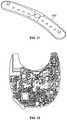
- FIG. 8illustrates an underside view of the head gear device of FIG. 6 ;
- FIG. 9illustrates a cut-away view of one embodiment of the track system of the head gear device of FIG. 6 ;
- FIGS. 10 a and 10 billustrate views of one embodiment of a sensor disposed within the headgear
- FIG. 11illustrates a connector device disposed within a cross-bar of the headgear
- FIG. 12illustrates one embodiment of a printed circuit board for functionality of the headgear device.
- the improved headgearincludes improvements in sensor connections, fashionable aspects, usability and integration of audio and/or video stimuli, for the measurement of electrophysiology data.
- the datais collected and processed in a local or networked or server-based processing environment.
- FIG. 1illustrates a measurement device used to measure the initial data.
- a helmet 100comprises at least one, or a plurality of, electrodes 106 (represented as white dots).
- the helmetmay be any receptacle that holds the electrodes in a position relative to the head of a wearer, or alternatively, electrodes may be taped or otherwise placed on the head.
- the helmet 100may also be updated using the headgear described below, wherein the headgear incorporates various helmet 100 aspects.
- Earphones 102 , goggles 104 and/or another display devicee.g. a small high-resolution display
- the electrodes 106are electrically connected to one of an electrical stimulation device 150 or electrical measuring device (e.g., a sensor), such as by way of amplifier 152 .
- the same electrode or electrodesmay be disconnected from one such device and connected to another such device, such as by way of changing an electrical pathway (switch) or by physically disconnecting an electrical wire from one device, and plugging into another.
- Other devicesinclude force platforms (measure postural deviations of person), devices to alter the display on the goggles 104 , and devices to alter the sound through the earphones 102 , and input devices such as a computer mouse, keyboards, and joysticks.
- the visual stimuli producedmay be an “immersive environment,” for example a virtual reality 2- or 3-dimension moving “room” displayed through a virtual reality headset.
- the data collected from the balance plate, heart rate monitor, EEG, and so forth,can be used in conjunction with the visual stimuli for neurophysiological trauma assessment and/or rehabilitation training.
- the data collected from this component, as well as all other componentsmay be linked with data collected from other components (e.g., EEG, ERP, ECG, balance) for assessment purposes.
- the system shown in FIG. 1may further comprise a vestibular activation test (VAT) headset permitting a computerized test that monitors the vestibulo-ocular reflex (VOR) during natural motion.
- a VAT headset useful for the systems described hereinmay produce images and/or record eye movements. Images displayed in the VAT headset may be generated by computer-implemented instructions and transmitted via electrical impulses to the VAT headset via wireless or direct connection. Eye movements may be recorded by way of the VAT headset.
- the VORis a reflex eye movement that stabilizes images on the retina during head movement by producing an eye movement in the direction opposite to head movement, thus preserving the image on the center of the visual field. As ocular trauma is often concomitant with traumatic brain injury, this component allows additional assessment of injury.
- the measurements of electrophysiological data of a patientmay include measurements acquired from dry or wet sensors or functional near infrared spectroscopy (fNIRs) optical fibers that send light into the scalp at wavelengths in the range of 650-850 nms.
- the sensors and/or fNIRsmay be attached to the non-invasive brain stimulation or modulation helmet/cap described herein.
- a patientmay refer to an individual under direct care or supervision of a doctor, but a patient is not so limited and may further include any suitable user or client wherein measurement data is acquired and analyzed as described herein.
- a patientmay include non-medically related uses, such as an athlete and the review/analysis of electrophysiological data of an athlete to analyze possible concussion data.
- Another example of a patientmay be soldiers with the review/analysis of electrophysiological data of the soldiers to analyze data relative to possible traumatic brain injury or post traumatic stress disorder.
- FIG. 2shows a high level block diagram of a method for acquiring the measurements.
- step 210non-invasive measurements are made of electrical current in the brain of a test subject. This is accomplished by way of electrodes placed on a test subject, such as in a helmet shown in FIG. 1 . In this manner, EEG and ERP signals may be recorded, measured, and analyzed.
- a single electrodemay be used to carry out the measuring in step 214 , or a plurality of electrode pairs may be used in step 212 .
- the position of the electrodesis known, and each electrode or a grouping thereof is placed over a definable region of the brain, the region defined by a person carrying out embodiments of the disclosed technology.
- the regionis defined as a specific brain area of interest for the recording, as defined by a person carrying out embodiments of the disclosed technology and may be a region covered by a single electrode pair or as large as half a hemisphere of a brain. Electrodes may also be grouped into clusters, such as with a single anode surrounded by three or more cathodes, or a single cathode surrounded by three or more anodes. Such clusters are electrically connected, such that electric current flows non-invasively through the proximal tissue from anode(s) to cathode(s), stimulating the brain (stimulating, herein is defined as passage of electrical current through the brain and includes increasing or decreasing neuron activity at a site). Thereby, the system can provide neurostimluation and/or neuromodulation to the user.
- step 220is also carried out which comprises providing sensory stimulus to a person. This may be done by way of, for example, the goggles shown in FIG. 1 for a visual stimulation 222 , auditory stimulation 224 , balance stimulation 226 , biofeedback measurements 228 , or other sensory stimulations known in the art.
- Stress tests and peak performance testsmay also be performed to determine, for example, how many times a minute a person is able to respond to a stimulus, or how long a person can hold his/her breath or balance on a force platform, etc.
- an abnormality in a region of the brainis determined in step 230 .
- An abnormalitymay be any of the following: electrical activity which is too infrequent, too frequent, too low in amplitude, too large in amplitude, an improper pattern of electrical activity, inter-intra-hemispheric connectivity, electrical activity in the wrong portion of the brain for the stimulus given, or the like.
- non-invasive brain stimulationsuch as tDCS or tACS
- tDCStDCS
- tACStACS
- the place of administeringmay be as little as a single anode/cathode pair (or cluster), or may use multiple anode/cathode pairs (or clusters).
- FIG. 3illustrates an embodiment of processing environment providing for the remote database and data analysis method and system operations.
- the local processing client 302may be any suitable local processing device including but not limited to the collection of measurement data, and/or one or more processing systems for executing interface operations.
- the local processing clientmay be a personal computer or a tablet computer having a browser or application for executing the interface functionality described herein.
- the network 304may be any suitable network providing communication thereacross.
- the network 302is an Internet connection across a public access network, wherein it is recognized that the network may include a private and/or secure network, as well as network exchanges via one or more service providers.
- the network 304operates to facilitate the communication of data between the local processing client 302 and the server-side network processing clients 306 .
- the server-side network processing clients 306may be any suitable number of network-processing devices.
- the client 306may be a dedicated processing server, wherein in another embodiment, the client 306 may be any suitable number of distributed computer resources for processing operations as described herein.
- FIG. 4shows a perspective view of a helmet with electrodes used in embodiments of the disclosed technology.
- the helmet 400comprises multiple electrodes, such as electrodes 442 , 444 , and 446 .
- a plurality of electrodesare spaced apart around the interior of a helmet or other piece of headgear and are adapted for both reading electrical activity from the brain of the wearer and delivering new impulses. That is, by way of a single electrode, plurality thereof, cluster of electrodes, or plurality of clusters, a joint brain electro-analysis and transcranial current stimulation system (tCS) comprises a plurality of spaced-apart removable and replaceable electrodes arranged in an item of headgear.
- An electroencephalography devicesuch as an EEG
- a transcranial direct current stimulation deviceat the same time or by way of a switch or plugging/unplugging a cable between the devices).
- cable 450allows for electrical connectivity between the electrodes and either or both of a tCS and EEG device.
- the cablemay be eliminated using wireless connectivity and communication techniques.
- a visor 460is integrated with the helmet in embodiments of the disclosed technology for optical stimulation (e.g. a video monitor).
- the visormay be an embedded display, as illustrated in FIG. 4 or in another embodiment may include an auxiliary or augmented display, such as pair of glasses or an immersive screen technology, as described in further detail below.
- transcranial direct current stimulationis engaged to at least one anode and at least one cathode electrode to the brain region where said anomaly was measured. Additional devices such as a force plate, visual stimuli utilizing interactive games and tests, and the like, may also be utilized.
- the tCSmay be transcranial direct current stimulation (tDCS) or transcranial alternating current stimulation (tACS).
- tDCStranscranial direct current stimulation
- tACStranscranial alternating current stimulation
- the datais collected and thus provided to one or more remote data processing systems.
- These remote data processing systemsmay be connected via a networked connection, including in one embodiment an Internet-based connection.
- the networkingmay be via a private or secure network.
- Internet-based connectionsinclude the processing of security features with the data, to insure the privacy of the data during transmission.
- one embodimentmay include a data collection computing device, such as a personal computer or other type of processing device, operative to receive the electrophysiology data.
- the processing device thereinprovides for the encryption or inclusion of security features on the data and the transmission to one or more designated locations.
- one embodimentmay include the compression of the data into a “.zip” file.
- the serverfurther provides for the storage of the data and retention of data information.
- the servercreates a postscript formatted file, such as a PDF file and the database is then updated to include storage of this information.
- the databasefurther includes enhancements to maximize storage, including determining if the data to be stored is duplicative. If the data is duplicative, a single data link can be provided, but if the data is not duplicative, then separate access to the data is provided.
- the data acquired from the devicemay be processed locally or across network.
- the user or clientis a doctor or other medical specialist having the ability to review, understand and advise a patient based on the data generated in the reports.
- the data generated in the reportsrelate to the electrophysiology data acquired from patients.
- the complete systemconsists of a wireless amplifier equipped to record artifact free electrical signals from the brain and heart and also position in space using a nine or greater accelerometer. This same device is configured to deliver electric current back to the sensors that are in contact with the scalp in order to facilitated non-invasive brain stimulation. Sensors make contact with this skin using either dry sensors or electro dermal gel or saline impregnated sensor for consistent sensor to skin connectivity measured by impedance.
- the softwareprovides for automated data collection using script software and self-guided instructions.
- the softwaresends the resulting data for algorithm processing either on the CPU or on a dedicated secure server through an internet connection. This data is processed on the CPU and processed either on the installed database and processing software or transmitted to the cloud-based server where processing takes place.
- the data analysisis returned in a report format showing physiology graphics and interpretive results from which the user can make intervention or diagnostic decisions.
- Comparison databasescan be selected from within the software to provide a comparison measure for the data analysis.
- Pre-set EEG training protocolse.g., theta:beta ratio training for attention; alpha:theta ratio training for relaxation
- EEG training protocolsare configured for automated home or clinic based training.
- Individual baseline datacan also be utilized so that the individual's data can be compared to an earlier data sample.
- An example of thisis a professional athlete having his or her pre-season baseline that is used for comparison following a concussion. This is particularly useful for single-subject design research of change over time and intervention results.
- Group databasessuch as peak performance or pathology comparison databases (i.e., Alzheimer's disease sample database) are also available for selection and data comparison.
- Intervention optionsinclude real-time noise and artifact removal algorithms that permit EEG and ECG training devoid of movement and other disruptive artifact or signal noise.
- tDCS/tACSnon-invasive brain stimulation
- sLORETA/eLORETA brain computer interfacewavelet time-frequency neurofeedback, event-related potential neurofeedback; Brodman Area selection, neurofeedback, neuro-network brain computer interface
- peripheral biofeedbacksuch as heart rate variability biofeedback
- the brain computer interface or neurofeedbackcan include any number of operations or techniques, including for example low resolution brain electromagnetic topography source localization feedback and surface electroencephalography amplitude or phase or coherence feedback.
- the userreceives report and intervention information from cloud-based server interface or from optional embedded software on the CPU for usage where internet connectivity is not possible.
- the results of the data analysisinclude a protocol that directs the non-invasive brain stimulation sensor placements and current parameters. These stimulation protocols can be manually or automatically selected to provide the user with both brain compute interface training and brain stimulation or brain modulation interventions.
- the rapid assessment and re-assessment of the brain and other measures included in the physiology measurement batteryallows for rapid determination of brain computer interface training location and frequency protocols and also brain stimulation or modulation using electric current.
- the re-assessmentquantifies the difference from the baseline measure in order to generate a report showing the change made by either or both brain computer interface and electric current brain modulation.
- Protocolswill vary based on the assessment results such that the different locations on the scalp may be stimulated with different polarity at the sensor and with more or less milliamps than one another. Users can manually define scalp location, polarity at the sensor, and milliamp levels and duration at each location. Users can also select from pre-defined protocols to increase or decrease regional neuronal activity.
- the same data analysis reportprovides illustration and instruction on the current flow through the brain tissue in order to further quantify the cortical excitability relevant to the users clinical or performance intent.
- Current flow reportingaid the user with further and more specific brain modulation targeting protocols using Talairach locations and Brodmann Areas.
- the availability of the data analysis and reports on the web portalallows for telemedicine access and review.
- the sensorspermit real time stimulation with electrical current and simultaneous recording of EEG using signal filters that remove the electrical stimulation and permit only the EEG and event related potentials to be recorded and processed. This feature permits the user to combine targeted brain stimulation with brain computer interface training using real time artifact correction. Simultaneous neurofeedback with stimulation allows for data analysis showing the focal changes or modulation in the brain from the individual or combined intervention modalities.
- FIG. 5illustrates a circular data flow diagram representing the circular operations described herein.
- Step 500includes the assessment and re-assessment protocols, such as EEG, ECG, Balance, ERP, etc.
- Step 502is the automated data analysis on a CPU or networked server.
- Step 504is the report output, which may include output in graphical format with interpretation data.
- the report 504may further include targeted brain stimulation protocol, functional training protocol with brain computer interface.
- step 506is the automated or manual selection of brain stimulation protocol and/or brain computer interface training protocol.
- Step 508is an optional real-time assessment during brain stimulation or brain computer interface training.
- Step 510provides automated reporting that reflects changes following brain intervention(s) with report output, which can be available to a user including HIPAA-compliant web or network portals.
- FIG. 6illustrates another embodiment of a device for collecting data and providing user feedback.
- This device 600includes earpieces 602 with speakers 604 .
- the device 600further includes a top cross-bar 606 and side-bars 608 , the bars, 606 and 608 , having a track 610 thereacross with sensors 612 disposed therein.
- the device 600additionally includes a hinge 614 for the side-bars 608 .
- Further embodimentsinclude an articulating arm 618 having a lens 620 thereon.
- the headgear 600may be composed of one or more suitable materials, including plastic, metal or carbon fiber by way of example.
- the earpieces 602are representative embodiments of engagement portions providing for engaging the user's head and securing placement of the sensors 612 .
- the speakers 604are disposed within the engagement portions of the earpieces 602 , providing for the audio output of sound consistent with known speaker technology.
- the earpiece 602 and speaker 604include cushioning 616 that not only improves user comfort in wearing the device, but also improves sound isolation of the speaker to minimize or reduce any ambient noise.
- the cross bar 606 and side bars 608include the track 610 that allows for the insertion of the sensors 612 .
- the sensors 612may be any suitable sensors that connect into the track for electrical connection with the device 600 .
- the sensors 612are dry sensors, where the dry sensors are attached using magnets for easy removal and replacement in-between users and for alternate sensor or electrode type attachments. The same system both provides EEG/ERP measures but also delivers brain stimulation using direct current and/or alternating current, as described above.
- the sensors 612When worn by a user, the sensors 612 are in contact with the user's cranium, wherein the location of the sensors 612 can be adjusted by movement of the sensor 612 along the track 610 within the cross-bars 606 and 608 .
- the hinge 612disposed on both sides of the cross-bar 606 , allows for the articulation of the of the side bars 608 away from or towards the cross-bar 608 . Therefore, when worn by the user, the sensor 612 location of the user's cranium can also be adjusted by the inward or outward articulation of the side bars 608 .
- the headgear 600allows for the visual display of content on the lens 620 .
- the positions or location of the lens 620 relative the usercan be adjusted by the adjustment of the arm 618 .
- the arm 618includes wiring (not readily visible) for providing an output signal to the lens 620 .
- the lens 620may be a high-definition lens operative to provide a visual output viewable by the user, where as described herein, the user can be subjected to visual stimuli for feedback generation via the headgear.
- the lens 620operates similar to the visual display goggles 104 of FIG. 1 or the visor 460 of FIG. 4 .
- FIG. 7illustrates a side view of the headgear 600 .
- the side viewillustrates the inward or outward articulation of the cross-bars 608 from a centerline of the cross-bar 606 .
- the headgear 600can be worn similar to commercially available musical headphones.
- the side viewadditionally illustrates the ear covering portions 602 .
- the earpiece 602includes processing functionality allowing for electrophysiological measurements and interaction.
- the lens 620extends outward via the arm 618 .
- FIG. 8illustrates a bottom or underside view of the headgear 600 , including the earpieces 602 , the cross-bar 606 , the side bars 608 , where the bars 606 and 608 include the tracks 610 and sensors 612 .
- the tracks 610extend across the bars 606 , 608 , allowing for adjusting the placement of the sensors 612 .
- the sensors 612can be located in the center (as illustrated), moved towards the left earpiece 602 or moved towards the right earpiece 602 .
- the location of the trackfurther allows for the placement of multiple sensors 612 on the track 610 , covering various regions of the user's cranium.
- FIG. 9illustrates a cross-section of the bars 606 , 608 .
- the tracksrun along the interior side of the crossbars 606 , 608 , with a gap allowing for the insertion of the sensor therein.
- FIG. 10 a and FIG. 10 billustrate perspective views of one embodiment of the sensors 612 .
- the top portion of the sensor 612includes connection members 620 for passing through the openings of the tracks 610 and inserting into an electrical channel disposed within the bars 606 , 608 .
- FIG. 11illustrates one embodiment of an electrical channel 630 housing within the crossbars 606 and 608 .
- the channel 630includes at least two channels for passing current, such as alternative or direct current) to the sensors, as well as for transmitting feedback readings from the sensor to one or more control units.
- the sensor 612snaps or engages the track 610 for being held in place, and the connectors 622 engage the electrical channel.
- the sensors 612may be moved lengthwise across the arch of the bars 606 , 608 , for different cranium engagement points on the user wearing the headgear.
- the dry sensorsare attached using magnets for easy removal and replacement in-between users and for alternate sensor or electrode type attachments.
- the same systemprovides EMG, EEG and/or ERP measurements but also delivers brain stimulation using direct and alternating current.
- FIG. 10 billustrates another perspective view of the sensor 612 , illustrating the downward portion of the sensor 612 that engages the user's cranium.
- the sensor 612is a dry contact sensor that includes a plurality of contact pins or engagement pins that are operative to transmit current into the user's scalp and/or receiving measurements or readings from the user's scalp.
- FIG. 12illustrates one embodiment of a printed circuit board disposed within the earpiece 602 on the headgear 600 .
- the printed circuit boardincludes processing operations for providing functionality as described herein.
- the circuit boardincludes, in one embodiment, wireless functionality allowing for the headgear 600 to not require a wired connection to a secondary computing device.
- the printed circuit boardprovides functionality for engaging the sensors in determining optimized placement, as well as execution of electrophysiology interaction.
- the headgearincludes additional functionality, which can be further beneficial for electrophysiological interaction.
- the headgearmay include a movement displacement sensor to detect head movement, as well as multi-dimensional plane orientation.
- inclusion of displacement technologycan help determine if the user is looking up, looking down, tilting his or her head, etc.
- the combined hardware sensor array, firmware, and software within the headset deviceincorporates high quality microphone for voice commands and phone calls and includes high fidelity speakers for listening to auditory prompts and to listen to music.
- materialsare hypoallergenic.
- Headsetis equipped with on-board circuitry for full signal processing and wireless transfer of data and real time clock and synchronization of stimulus presentation and measured physiology and balance or movement.
- the headsetis charged using contact charging points, where further embodiments may utilize any other suitable charging or re-charging technique.
- the headsetincludes a power engagement button for powering on and turning off the headset.
- the power engagement buttonmay be centrally located within an outside cover of the engagement portion.
- Headset designpermits multiple magnetic attached scalp sensor and proximity sensors that allow recording of EEG and ECG/BVP physiology data.
- the headsethas the advantage of being as fully functional as the higher end headphones but also adding brain computer interface and heart computer interface recording and modulation components.
- the deviceuses non-contact dry sensors to measure heart rate variability and EEG.
- the systemcan measure, record, and process within the headset circuitry the electrophysiology and transmit data in pre or post-processed form for remote cloud-based analysis or on the imbedded computer processing unit.
- real-time artifact correction algorithmsthe device is able to provide feedback to the user of EEG and blood volume pulse signal.
- the systemfurther provides for EMG feedback and ECG feedback.
- Video gamesare made further interactive with the condition of the human electrophysiology utilizing specific neuro-networks of the brain and particular regions of the brain responsible for different brain functions such as attention, language processing, memory processing, executive functions, affect, emotional processing.
- the lens 620allows for the user to be placed in an immersive environment and engage in various degrees of interactivity.
- interactivityis engaging video games where the user play can be directly influenced by the measured feedback from the headgear 100 or 600 .
- the gamemay integrate EEG features relative to the avatar or video game character, where those features are measured from the user.
- Another example of interactivityis neuromarketing, whereby the headgear 600 allows for collection of neurological data relating to marketing.
- data collectioncan include tracking users as they view commercials, collecting electrophysiology measurements.
- Another examplemay be having the user wear the device and actively enter a retail establishment or other arena in which the user is subjected to marketing, again measuring electrophysiology data.
- the headgear assemblyimproves upon prior headgear for not only data collection techniques, but also wearability.
- the inclusion of adjustability of the placement of the sensorsprovides a wider degree of usability and testability by displacing the sensors at various locations by adjusting the position of the sensors within the track and adjusting the position of the track over the user's cranium by articulating the bars 608 .
Landscapes
- Health & Medical Sciences (AREA)
- Life Sciences & Earth Sciences (AREA)
- Engineering & Computer Science (AREA)
- Biomedical Technology (AREA)
- General Health & Medical Sciences (AREA)
- Veterinary Medicine (AREA)
- Public Health (AREA)
- Animal Behavior & Ethology (AREA)
- Heart & Thoracic Surgery (AREA)
- Biophysics (AREA)
- Medical Informatics (AREA)
- Molecular Biology (AREA)
- Surgery (AREA)
- Physics & Mathematics (AREA)
- Pathology (AREA)
- Nuclear Medicine, Radiotherapy & Molecular Imaging (AREA)
- Radiology & Medical Imaging (AREA)
- Psychology (AREA)
- Psychiatry (AREA)
- Neurology (AREA)
- Developmental Disabilities (AREA)
- Hospice & Palliative Care (AREA)
- Child & Adolescent Psychology (AREA)
- Social Psychology (AREA)
- Computer Networks & Wireless Communication (AREA)
- Physiology (AREA)
- Measurement And Recording Of Electrical Phenomena And Electrical Characteristics Of The Living Body (AREA)
Abstract
Description
Claims (17)
Priority Applications (2)
| Application Number | Priority Date | Filing Date | Title |
|---|---|---|---|
| US15/678,316US10660537B2 (en) | 2010-01-06 | 2017-08-16 | Headgear with displaceable sensors for electrophysiology measurement and training |
| US15/930,280US20200268272A1 (en) | 2010-01-06 | 2020-05-12 | Headgear with displaceable sensors for electrophysiology measurement and training |
Applications Claiming Priority (7)
| Application Number | Priority Date | Filing Date | Title |
|---|---|---|---|
| US29279110P | 2010-01-06 | 2010-01-06 | |
| US12/979,419US8239030B1 (en) | 2010-01-06 | 2010-12-28 | Transcranial stimulation device and method based on electrophysiological testing |
| US13/543,204US8380316B2 (en) | 2010-01-06 | 2012-07-06 | Transcranial stimulation device and method based on electrophysiological testing |
| US13/742,066US8838247B2 (en) | 2010-01-06 | 2013-01-15 | Transcranial stimulation device and method based on electrophysiological testing |
| US14/458,673US8938301B2 (en) | 2010-01-06 | 2014-08-13 | Headgear with displaceable sensors for electrophysiology measurement and training |
| US14/568,385US9788747B2 (en) | 2010-01-06 | 2014-12-12 | Headgear with displaceable sensors for electrophysiology measurement and training |
| US15/678,316US10660537B2 (en) | 2010-01-06 | 2017-08-16 | Headgear with displaceable sensors for electrophysiology measurement and training |
Related Parent Applications (1)
| Application Number | Title | Priority Date | Filing Date |
|---|---|---|---|
| US14/568,385ContinuationUS9788747B2 (en) | 2010-01-06 | 2014-12-12 | Headgear with displaceable sensors for electrophysiology measurement and training |
Related Child Applications (1)
| Application Number | Title | Priority Date | Filing Date |
|---|---|---|---|
| US15/930,280ContinuationUS20200268272A1 (en) | 2010-01-06 | 2020-05-12 | Headgear with displaceable sensors for electrophysiology measurement and training |
Publications (2)
| Publication Number | Publication Date |
|---|---|
| US20180020941A1 US20180020941A1 (en) | 2018-01-25 |
| US10660537B2true US10660537B2 (en) | 2020-05-26 |
Family
ID=51935819
Family Applications (5)
| Application Number | Title | Priority Date | Filing Date |
|---|---|---|---|
| US14/458,673ActiveUS8938301B2 (en) | 2009-12-28 | 2014-08-13 | Headgear with displaceable sensors for electrophysiology measurement and training |
| US14/516,207ActiveUS8942813B1 (en) | 2010-01-06 | 2014-10-16 | Transcranial stimulation device and method based on electrophysiological testing |
| US14/568,385ActiveUS9788747B2 (en) | 2010-01-06 | 2014-12-12 | Headgear with displaceable sensors for electrophysiology measurement and training |
| US15/678,316Active2031-07-30US10660537B2 (en) | 2010-01-06 | 2017-08-16 | Headgear with displaceable sensors for electrophysiology measurement and training |
| US15/930,280AbandonedUS20200268272A1 (en) | 2010-01-06 | 2020-05-12 | Headgear with displaceable sensors for electrophysiology measurement and training |
Family Applications Before (3)
| Application Number | Title | Priority Date | Filing Date |
|---|---|---|---|
| US14/458,673ActiveUS8938301B2 (en) | 2009-12-28 | 2014-08-13 | Headgear with displaceable sensors for electrophysiology measurement and training |
| US14/516,207ActiveUS8942813B1 (en) | 2010-01-06 | 2014-10-16 | Transcranial stimulation device and method based on electrophysiological testing |
| US14/568,385ActiveUS9788747B2 (en) | 2010-01-06 | 2014-12-12 | Headgear with displaceable sensors for electrophysiology measurement and training |
Family Applications After (1)
| Application Number | Title | Priority Date | Filing Date |
|---|---|---|---|
| US15/930,280AbandonedUS20200268272A1 (en) | 2010-01-06 | 2020-05-12 | Headgear with displaceable sensors for electrophysiology measurement and training |
Country Status (1)
| Country | Link |
|---|---|
| US (5) | US8938301B2 (en) |
Cited By (6)
| Publication number | Priority date | Publication date | Assignee | Title |
|---|---|---|---|---|
| US11076797B2 (en) | 2018-04-10 | 2021-08-03 | Cerenetex, Inc. | Systems and methods for the identification of medical conditions, and determination of appropriate therapies, by passively detecting acoustic signals from cerebral vasculature |
| US20210393473A1 (en)* | 2018-10-12 | 2021-12-23 | Bodyfriend Co., Ltd. | Massage device comprising body composition measurement module for body composition measurement, and method of controlling same |
| US11992678B2 (en) | 2017-11-17 | 2024-05-28 | Flow Neuroscience, Inc. | System and method for individualizing neuromodulation |
| US12004846B2 (en) | 2018-04-10 | 2024-06-11 | Cerenetex, Inc. | Non-invasive systems and methods for the improved evaluation of patients suffering from undiagnosed headaches |
| US12011590B2 (en) | 2013-08-27 | 2024-06-18 | Flow Neuroscience, Inc. | Method and system for providing electrical stimulation to a user |
| US12157005B2 (en) | 2013-08-27 | 2024-12-03 | Flow Neuroscience, Inc. | Method and system for providing electrical stimulation to a user |
Families Citing this family (69)
| Publication number | Priority date | Publication date | Assignee | Title |
|---|---|---|---|---|
| US8684742B2 (en) | 2010-04-19 | 2014-04-01 | Innerscope Research, Inc. | Short imagery task (SIT) research method |
| US8655428B2 (en) | 2010-05-12 | 2014-02-18 | The Nielsen Company (Us), Llc | Neuro-response data synchronization |
| US8392250B2 (en)* | 2010-08-09 | 2013-03-05 | The Nielsen Company (Us), Llc | Neuro-response evaluated stimulus in virtual reality environments |
| US9569986B2 (en) | 2012-02-27 | 2017-02-14 | The Nielsen Company (Us), Llc | System and method for gathering and analyzing biometric user feedback for use in social media and advertising applications |
| JP2016501056A (en)* | 2012-11-10 | 2016-01-18 | ザ レジェンツ オブ ザ ユニヴァーシティー オブ カリフォルニア | System and method for evaluation of neuropathology |
| US9486618B2 (en) | 2013-08-27 | 2016-11-08 | Halo Neuro, Inc. | Electrode system for electrical stimulation |
| US9889290B2 (en) | 2013-08-27 | 2018-02-13 | Halo Neuro, Inc. | Electrode system for electrical stimulation |
| US9687037B1 (en)* | 2014-02-06 | 2017-06-27 | Virginia Commonwealth University | Magnetic football helmet to reduce concussion injuries |
| US10542904B2 (en)* | 2014-04-23 | 2020-01-28 | Case Western Reserve University | Systems and methods for at home neural recording |
| CA2951689C (en)* | 2014-06-09 | 2023-01-10 | Neurolutions, Inc. | Brain-computer interface headset |
| USD743039S1 (en)* | 2014-08-13 | 2015-11-10 | Evoke Neuroscience, Inc. | Headgear for electrophysiology measurement and training |
| KR101539654B1 (en) | 2014-11-27 | 2015-07-27 | (주)와이브레인 | Electric device for measuring eeg signal or electric stimulation |
| CN104605849A (en)* | 2015-01-14 | 2015-05-13 | 江正国 | Electroencephalogram biological feedback diagnosis and treatment instrument and system and using method |
| US10013808B2 (en) | 2015-02-03 | 2018-07-03 | Globus Medical, Inc. | Surgeon head-mounted display apparatuses |
| GB201503004D0 (en)* | 2015-02-23 | 2015-04-08 | Univ Swansea | Apparatus for altering the mood of an individual |
| EP3268948A4 (en)* | 2015-03-10 | 2018-10-17 | HRL Laboratories, LLC | System and method for training and assessment |
| US10328852B2 (en)* | 2015-05-12 | 2019-06-25 | University Of North Dakota | Systems and methods to provide feedback to pilot/operator by utilizing integration of navigation and physiological monitoring |
| US9936250B2 (en) | 2015-05-19 | 2018-04-03 | The Nielsen Company (Us), Llc | Methods and apparatus to adjust content presented to an individual |
| EP3302251A4 (en)* | 2015-05-27 | 2019-05-08 | Merlin Digital General Trading LLC | Biofeedback virtual reality system and method |
| CN108135473A (en)* | 2015-07-31 | 2018-06-08 | 巴塞罗纳大学 | Physiological reaction |
| KR101733104B1 (en)* | 2015-10-08 | 2017-05-08 | 연세대학교 산학협력단 | Brain Stimulation Device for Treatment |
| CN108290037B (en)* | 2015-10-26 | 2021-10-08 | 福禄神经学公司 | Electrode positioning system and method |
| USD797074S1 (en)* | 2016-02-02 | 2017-09-12 | Halo Neuro, Inc. | Biointerface headset |
| US10315033B2 (en) | 2016-02-08 | 2019-06-11 | Halo Neuro, Inc. | Method and system for improving provision of electrical stimulation |
| US10485443B2 (en) | 2016-06-20 | 2019-11-26 | Halo Neuro, Inc. | Electrical interface system |
| CN106420322A (en)* | 2016-09-21 | 2017-02-22 | 林日中 | Magneto-electric AC-DC magnetic therapy acupuncture and moxibustion device for treating cold arthralgia and myalgia by dredging blood |
| US11540759B2 (en) | 2016-09-29 | 2023-01-03 | Mindset Innovation Inc. | Biosignal headphones |
| US11344723B1 (en) | 2016-10-24 | 2022-05-31 | Hrl Laboratories, Llc | System and method for decoding and behaviorally validating memory consolidation during sleep from EEG after waking experience |
| FR3058628B1 (en)* | 2016-11-15 | 2021-07-30 | Cosciens | DEVICE FOR MEASURING AND / OR STIMULATING BRAIN ACTIVITY |
| EP3576835B1 (en) | 2017-02-02 | 2023-08-02 | Flow Neuroscience AB | Headset for transcranial direct-current stimulation, tdcs, and a system comprising the headset |
| US10525255B2 (en) | 2017-03-08 | 2020-01-07 | Halo Neuro, Inc. | System for electrical stimulation |
| CN110325242B (en)* | 2017-03-29 | 2023-06-27 | 赫尔实验室有限公司 | Transcranial current stimulation system and virtual reality for treating PTSD or fear |
| US10326235B2 (en)* | 2017-04-18 | 2019-06-18 | Facebook Technologies, Llc | Electromagnetic connections for dynamically mating and un-mating a wired head-mounted display |
| US11723579B2 (en) | 2017-09-19 | 2023-08-15 | Neuroenhancement Lab, LLC | Method and apparatus for neuroenhancement |
| WO2019100378A1 (en)* | 2017-11-27 | 2019-05-31 | 深圳市汇顶科技股份有限公司 | Earphones, method for detecting wearing state of earphones, and electronic device |
| US10582316B2 (en) | 2017-11-30 | 2020-03-03 | Starkey Laboratories, Inc. | Ear-worn electronic device incorporating motor brain-computer interface |
| US11717686B2 (en) | 2017-12-04 | 2023-08-08 | Neuroenhancement Lab, LLC | Method and apparatus for neuroenhancement to facilitate learning and performance |
| PL423873A1 (en)* | 2017-12-13 | 2019-06-17 | Uniwersytet Medyczny w Łodzi | Magnetic field inductor, a kit for diagnosis and/or therapy of ear buzzing and the system for electric and magnetic stimulation of ear |
| US12280219B2 (en) | 2017-12-31 | 2025-04-22 | NeuroLight, Inc. | Method and apparatus for neuroenhancement to enhance emotional response |
| US11273283B2 (en) | 2017-12-31 | 2022-03-15 | Neuroenhancement Lab, LLC | Method and apparatus for neuroenhancement to enhance emotional response |
| CN108310659A (en)* | 2018-02-12 | 2018-07-24 | 四川大学 | Wear-type pulsed electromagnetic field therapy instrument |
| US20190254753A1 (en) | 2018-02-19 | 2019-08-22 | Globus Medical, Inc. | Augmented reality navigation systems for use with robotic surgical systems and methods of their use |
| GB201805555D0 (en)* | 2018-04-04 | 2018-05-16 | Cerebrum Matter Ltd | System for monitoring brain wave activity |
| US11364361B2 (en) | 2018-04-20 | 2022-06-21 | Neuroenhancement Lab, LLC | System and method for inducing sleep by transplanting mental states |
| EP3603737B1 (en) | 2018-07-31 | 2020-08-26 | Flow Neuroscience AB | Positioning of electrodes for transcranial brain stimulation |
| WO2020033883A1 (en)* | 2018-08-09 | 2020-02-13 | Global Continence Llc | Transcutaneous electrical nerve stimulation for treating enuresis and pelvic floor disorders |
| EP3849410A4 (en) | 2018-09-14 | 2022-11-02 | Neuroenhancement Lab, LLC | SLEEP ENHANCEMENT SYSTEM AND METHOD |
| USD966539S1 (en)* | 2020-05-05 | 2022-10-11 | Kamran Ansari | Head covering for use as a repetitive transcranial magnetic stimulation device |
| USD999388S1 (en)* | 2020-05-05 | 2023-09-19 | Kamran Ansari | Transcranial stimulation device |
| USD1006240S1 (en)* | 2019-05-06 | 2023-11-28 | Kamran Ansari | Transcranial magnetic stimulation device |
| US11786694B2 (en) | 2019-05-24 | 2023-10-17 | NeuroLight, Inc. | Device, method, and app for facilitating sleep |
| US12133772B2 (en) | 2019-12-10 | 2024-11-05 | Globus Medical, Inc. | Augmented reality headset for navigated robotic surgery |
| US11992373B2 (en) | 2019-12-10 | 2024-05-28 | Globus Medical, Inc | Augmented reality headset with varied opacity for navigated robotic surgery |
| US12220176B2 (en) | 2019-12-10 | 2025-02-11 | Globus Medical, Inc. | Extended reality instrument interaction zone for navigated robotic |
| US11464581B2 (en) | 2020-01-28 | 2022-10-11 | Globus Medical, Inc. | Pose measurement chaining for extended reality surgical navigation in visible and near infrared spectrums |
| US11382699B2 (en) | 2020-02-10 | 2022-07-12 | Globus Medical Inc. | Extended reality visualization of optical tool tracking volume for computer assisted navigation in surgery |
| US11207150B2 (en) | 2020-02-19 | 2021-12-28 | Globus Medical, Inc. | Displaying a virtual model of a planned instrument attachment to ensure correct selection of physical instrument attachment |
| US11607277B2 (en) | 2020-04-29 | 2023-03-21 | Globus Medical, Inc. | Registration of surgical tool with reference array tracked by cameras of an extended reality headset for assisted navigation during surgery |
| USD1006241S1 (en)* | 2020-05-05 | 2023-11-28 | Kamran Ansari | Transcranial magnetic stimulation device |
| US11153555B1 (en) | 2020-05-08 | 2021-10-19 | Globus Medical Inc. | Extended reality headset camera system for computer assisted navigation in surgery |
| US11510750B2 (en) | 2020-05-08 | 2022-11-29 | Globus Medical, Inc. | Leveraging two-dimensional digital imaging and communication in medicine imagery in three-dimensional extended reality applications |
| US11382700B2 (en) | 2020-05-08 | 2022-07-12 | Globus Medical Inc. | Extended reality headset tool tracking and control |
| DE102020114745A1 (en)* | 2020-06-03 | 2021-12-09 | NeuroCare Group GmbH | Body condition-dependent stimulation with real-time communication between an action module and a detection module |
| CN111973880A (en)* | 2020-06-11 | 2020-11-24 | 天津工业大学 | Mental fatigue intervention equipment and intervention method |
| US11737831B2 (en) | 2020-09-02 | 2023-08-29 | Globus Medical Inc. | Surgical object tracking template generation for computer assisted navigation during surgical procedure |
| CN112971788B (en)* | 2020-11-19 | 2023-03-31 | 首都医科大学宣武医院 | Split pressing multifunctional electroencephalogram cap |
| CN114306944A (en)* | 2022-01-21 | 2022-04-12 | 中国科学院电工研究所 | Portable magneto-optical stimulation device for improving cognitive impairment caused by Alzheimer's disease |
| US11793434B1 (en)* | 2022-05-18 | 2023-10-24 | GM Global Technology Operations LLC | System to perform visual recognition and vehicle adaptation |
| WO2024026392A2 (en)* | 2022-07-27 | 2024-02-01 | Pigpug, Inc. | Systems including wearable electroencephalography devices with movable band(s) and methods of use thereof |
Citations (23)
| Publication number | Priority date | Publication date | Assignee | Title |
|---|---|---|---|---|
| US2549836A (en)* | 1946-06-14 | 1951-04-24 | Archibald R Mcintyre | Electrode-carrying headgear for electroencephalographic analysis |
| US3735753A (en)* | 1971-11-09 | 1973-05-29 | Humetrics Corp | Head harness for eeg electrodes |
| US3998213A (en)* | 1975-04-08 | 1976-12-21 | Bio-Volt Corporation | Self-adjustable holder for automatically positioning electroencephalographic electrodes |
| US20020029005A1 (en)* | 1999-02-05 | 2002-03-07 | Levendowski Daniel J. | Portable EEG electrode locator headgear |
| US20020128541A1 (en)* | 2001-02-26 | 2002-09-12 | Kim Sun-Ii | Visual displaying device for virtual reality with a built-in biofeedback sensor |
| US6461297B1 (en)* | 2001-02-16 | 2002-10-08 | Guido Pagnacco | Apparatus and methods for measuring physical disorders |
| US20020188216A1 (en)* | 2001-05-03 | 2002-12-12 | Kayyali Hani Akram | Head mounted medical device |
| US20030028072A1 (en)* | 2000-08-31 | 2003-02-06 | Neuropace, Inc. | Low frequency magnetic neurostimulator for the treatment of neurological disorders |
| US20040193068A1 (en)* | 2001-06-13 | 2004-09-30 | David Burton | Methods and apparatus for monitoring consciousness |
| US20050197556A1 (en)* | 2004-02-27 | 2005-09-08 | Stoler Diane R. | Continuously adjustable neurofeedback device |
| US20050273017A1 (en)* | 2004-03-26 | 2005-12-08 | Evian Gordon | Collective brain measurement system and method |
| US20070027406A1 (en)* | 2004-02-13 | 2007-02-01 | Georgia Tech Research Corporation | Display enhanced testing for concussions and mild traumatic brain injury |
| US20070273504A1 (en)* | 2006-05-16 | 2007-11-29 | Bao Tran | Mesh network monitoring appliance |
| US20080001735A1 (en)* | 2006-06-30 | 2008-01-03 | Bao Tran | Mesh network personal emergency response appliance |
| US20080103483A1 (en)* | 2006-10-30 | 2008-05-01 | Johnson Benjamin A | Infusion catheter with composite tip |
| US20090088619A1 (en)* | 2007-10-01 | 2009-04-02 | Quantum Applied Science & Research, Inc. | Self-Locating Sensor Mounting Apparatus |
| US20090099623A1 (en)* | 2004-09-13 | 2009-04-16 | Neuronix Ltd. | Systems and methods for treatment of medical conditions related to the central nervous system and for enhancing cognitive functions |
| US20100024829A1 (en)* | 2006-10-06 | 2010-02-04 | Orsa S.R.L. | Relaxant device of muscle fascicles in the cervical district |
| US20100100001A1 (en)* | 2007-12-27 | 2010-04-22 | Teledyne Scientific & Imaging, Llc | Fixation-locked measurement of brain responses to stimuli |
| US20100113959A1 (en)* | 2006-03-07 | 2010-05-06 | Beth Israel Deaconess Medical Center, Inc. | Transcranial magnetic stimulation (tms) methods and apparatus |
| US20110015539A1 (en)* | 2001-01-30 | 2011-01-20 | Decharms R Christopher | Methods for physiological monitoring, training, exercise and regulation |
| US20110137381A1 (en)* | 2006-07-05 | 2011-06-09 | Harry Lee | Treatment of neurological disorders via electrical stimulation, and methods related thereto |
| US20110275927A1 (en)* | 2006-06-19 | 2011-11-10 | Highland Instruments, Inc. | Systems and methods for stimulating and monitoring biological tissue |
Family Cites Families (3)
| Publication number | Priority date | Publication date | Assignee | Title |
|---|---|---|---|---|
| US20080319505A1 (en)* | 2007-05-09 | 2008-12-25 | Massachusetts Institute Of Technology | Integrated Transcranial Current Stimulation and Electroencephalography Device |
| EP2419172A4 (en)* | 2009-04-13 | 2014-03-12 | Univ City New York Res Found | Transcranial stimulation |
| US20110224571A1 (en)* | 2009-11-16 | 2011-09-15 | Alvaro Pascual-Leone | Non-invasive methods for evaluating cortical plasticity impairments |
- 2014
- 2014-08-13USUS14/458,673patent/US8938301B2/enactiveActive
- 2014-10-16USUS14/516,207patent/US8942813B1/enactiveActive
- 2014-12-12USUS14/568,385patent/US9788747B2/enactiveActive
- 2017
- 2017-08-16USUS15/678,316patent/US10660537B2/enactiveActive
- 2020
- 2020-05-12USUS15/930,280patent/US20200268272A1/ennot_activeAbandoned
Patent Citations (23)
| Publication number | Priority date | Publication date | Assignee | Title |
|---|---|---|---|---|
| US2549836A (en)* | 1946-06-14 | 1951-04-24 | Archibald R Mcintyre | Electrode-carrying headgear for electroencephalographic analysis |
| US3735753A (en)* | 1971-11-09 | 1973-05-29 | Humetrics Corp | Head harness for eeg electrodes |
| US3998213A (en)* | 1975-04-08 | 1976-12-21 | Bio-Volt Corporation | Self-adjustable holder for automatically positioning electroencephalographic electrodes |
| US20020029005A1 (en)* | 1999-02-05 | 2002-03-07 | Levendowski Daniel J. | Portable EEG electrode locator headgear |
| US20030028072A1 (en)* | 2000-08-31 | 2003-02-06 | Neuropace, Inc. | Low frequency magnetic neurostimulator for the treatment of neurological disorders |
| US20110015539A1 (en)* | 2001-01-30 | 2011-01-20 | Decharms R Christopher | Methods for physiological monitoring, training, exercise and regulation |
| US6461297B1 (en)* | 2001-02-16 | 2002-10-08 | Guido Pagnacco | Apparatus and methods for measuring physical disorders |
| US20020128541A1 (en)* | 2001-02-26 | 2002-09-12 | Kim Sun-Ii | Visual displaying device for virtual reality with a built-in biofeedback sensor |
| US20020188216A1 (en)* | 2001-05-03 | 2002-12-12 | Kayyali Hani Akram | Head mounted medical device |
| US20040193068A1 (en)* | 2001-06-13 | 2004-09-30 | David Burton | Methods and apparatus for monitoring consciousness |
| US20070027406A1 (en)* | 2004-02-13 | 2007-02-01 | Georgia Tech Research Corporation | Display enhanced testing for concussions and mild traumatic brain injury |
| US20050197556A1 (en)* | 2004-02-27 | 2005-09-08 | Stoler Diane R. | Continuously adjustable neurofeedback device |
| US20050273017A1 (en)* | 2004-03-26 | 2005-12-08 | Evian Gordon | Collective brain measurement system and method |
| US20090099623A1 (en)* | 2004-09-13 | 2009-04-16 | Neuronix Ltd. | Systems and methods for treatment of medical conditions related to the central nervous system and for enhancing cognitive functions |
| US20100113959A1 (en)* | 2006-03-07 | 2010-05-06 | Beth Israel Deaconess Medical Center, Inc. | Transcranial magnetic stimulation (tms) methods and apparatus |
| US20070273504A1 (en)* | 2006-05-16 | 2007-11-29 | Bao Tran | Mesh network monitoring appliance |
| US20110275927A1 (en)* | 2006-06-19 | 2011-11-10 | Highland Instruments, Inc. | Systems and methods for stimulating and monitoring biological tissue |
| US20080001735A1 (en)* | 2006-06-30 | 2008-01-03 | Bao Tran | Mesh network personal emergency response appliance |
| US20110137381A1 (en)* | 2006-07-05 | 2011-06-09 | Harry Lee | Treatment of neurological disorders via electrical stimulation, and methods related thereto |
| US20100024829A1 (en)* | 2006-10-06 | 2010-02-04 | Orsa S.R.L. | Relaxant device of muscle fascicles in the cervical district |
| US20080103483A1 (en)* | 2006-10-30 | 2008-05-01 | Johnson Benjamin A | Infusion catheter with composite tip |
| US20090088619A1 (en)* | 2007-10-01 | 2009-04-02 | Quantum Applied Science & Research, Inc. | Self-Locating Sensor Mounting Apparatus |
| US20100100001A1 (en)* | 2007-12-27 | 2010-04-22 | Teledyne Scientific & Imaging, Llc | Fixation-locked measurement of brain responses to stimuli |
Cited By (6)
| Publication number | Priority date | Publication date | Assignee | Title |
|---|---|---|---|---|
| US12011590B2 (en) | 2013-08-27 | 2024-06-18 | Flow Neuroscience, Inc. | Method and system for providing electrical stimulation to a user |
| US12157005B2 (en) | 2013-08-27 | 2024-12-03 | Flow Neuroscience, Inc. | Method and system for providing electrical stimulation to a user |
| US11992678B2 (en) | 2017-11-17 | 2024-05-28 | Flow Neuroscience, Inc. | System and method for individualizing neuromodulation |
| US11076797B2 (en) | 2018-04-10 | 2021-08-03 | Cerenetex, Inc. | Systems and methods for the identification of medical conditions, and determination of appropriate therapies, by passively detecting acoustic signals from cerebral vasculature |
| US12004846B2 (en) | 2018-04-10 | 2024-06-11 | Cerenetex, Inc. | Non-invasive systems and methods for the improved evaluation of patients suffering from undiagnosed headaches |
| US20210393473A1 (en)* | 2018-10-12 | 2021-12-23 | Bodyfriend Co., Ltd. | Massage device comprising body composition measurement module for body composition measurement, and method of controlling same |
Also Published As
| Publication number | Publication date |
|---|---|
| US20200268272A1 (en) | 2020-08-27 |
| US8942813B1 (en) | 2015-01-27 |
| US20180020941A1 (en) | 2018-01-25 |
| US20150045606A1 (en) | 2015-02-12 |
| US8938301B2 (en) | 2015-01-20 |
| US9788747B2 (en) | 2017-10-17 |
| US20170027467A1 (en) | 2017-02-02 |
| US20140350431A1 (en) | 2014-11-27 |
Similar Documents
| Publication | Publication Date | Title |
|---|---|---|
| US10660537B2 (en) | Headgear with displaceable sensors for electrophysiology measurement and training | |
| US11464973B2 (en) | Transcranial stimulation device and method based on electrophysiological testing | |
| US12427312B2 (en) | Transcranial stimulation device and method based on electrophysiological testing | |
| CN110167630B (en) | Multifunctional closed-loop nerve feedback stimulation equipment and method thereof | |
| US20240023892A1 (en) | Method and system for collecting and processing bioelectrical signals | |
| US8380316B2 (en) | Transcranial stimulation device and method based on electrophysiological testing | |
| Bleichner et al. | Concealed, unobtrusive ear-centered EEG acquisition: cEEGrids for transparent EEG | |
| US8838247B2 (en) | Transcranial stimulation device and method based on electrophysiological testing | |
| CN103720470B (en) | Systems and methods for collecting and analyzing electroencephalogram data | |
| KR20160055103A (en) | System and signatures for the multi-modal physiological stimulation and assessment of brain health | |
| US12115369B1 (en) | Galvanic vestibular stimulation (GVS) systems, devices and methods | |
| Dastgheib et al. | The evolution of Electrovestibulography technique and safety considerations | |
| Wheeler | In-Ear EEG Device for Auditory Brain-Computer Interface Communication | |
| HK40012217A (en) | A method and system for collecting and analyzing electroencephalographic data | |
| HK40012217B (en) | A method and system for collecting and analyzing electroencephalographic data | |
| HK1228237A1 (en) | Systems and methods to gather and analyze electroencephalographic data | |
| HK1196522B (en) | Systems and methods to gather and analyze electroencephalographic data |
Legal Events
| Date | Code | Title | Description |
|---|---|---|---|
| AS | Assignment | Owner name:EVOKE NEUROSCIENCE, INC., NORTH CAROLINA Free format text:ASSIGNMENT OF ASSIGNORS INTEREST;ASSIGNOR:HAGEDORN, DAVID;REEL/FRAME:043304/0760 Effective date:20140820 | |
| FEPP | Fee payment procedure | Free format text:ENTITY STATUS SET TO SMALL (ORIGINAL EVENT CODE: SMAL); ENTITY STATUS OF PATENT OWNER: SMALL ENTITY | |
| STPP | Information on status: patent application and granting procedure in general | Free format text:DOCKETED NEW CASE - READY FOR EXAMINATION | |
| STPP | Information on status: patent application and granting procedure in general | Free format text:NON FINAL ACTION MAILED | |
| STPP | Information on status: patent application and granting procedure in general | Free format text:FINAL REJECTION MAILED | |
| STPP | Information on status: patent application and granting procedure in general | Free format text:RESPONSE AFTER FINAL ACTION FORWARDED TO EXAMINER | |
| STPP | Information on status: patent application and granting procedure in general | Free format text:NOTICE OF ALLOWANCE MAILED -- APPLICATION RECEIVED IN OFFICE OF PUBLICATIONS | |
| STPP | Information on status: patent application and granting procedure in general | Free format text:PUBLICATIONS -- ISSUE FEE PAYMENT VERIFIED | |
| STCF | Information on status: patent grant | Free format text:PATENTED CASE | |
| FEPP | Fee payment procedure | Free format text:MAINTENANCE FEE REMINDER MAILED (ORIGINAL EVENT CODE: REM.); ENTITY STATUS OF PATENT OWNER: SMALL ENTITY | |
| FEPP | Fee payment procedure | Free format text:SURCHARGE FOR LATE PAYMENT, SMALL ENTITY (ORIGINAL EVENT CODE: M2554); ENTITY STATUS OF PATENT OWNER: SMALL ENTITY | |
| MAFP | Maintenance fee payment | Free format text:PAYMENT OF MAINTENANCE FEE, 4TH YR, SMALL ENTITY (ORIGINAL EVENT CODE: M2551); ENTITY STATUS OF PATENT OWNER: SMALL ENTITY Year of fee payment:4 | |
| AS | Assignment | Owner name:FIREFLY NEUROSCIENCE, INC., NEW YORK Free format text:ASSIGNMENT OF ASSIGNORS INTEREST;ASSIGNOR:EVOKE NEUROSCIENCE, INC.;REEL/FRAME:072066/0976 Effective date:20250514 |