US10657671B2 - System and method for navigation to a target anatomical object in medical imaging-based procedures - Google Patents
System and method for navigation to a target anatomical object in medical imaging-based proceduresDownload PDFInfo
- Publication number
- US10657671B2 US10657671B2US15/736,129US201715736129AUS10657671B2US 10657671 B2US10657671 B2US 10657671B2US 201715736129 AUS201715736129 AUS 201715736129AUS 10657671 B2US10657671 B2US 10657671B2
- Authority
- US
- United States
- Prior art keywords
- imaging system
- deep learning
- scenes
- learning network
- medical imaging
- Prior art date
- Legal status (The legal status is an assumption and is not a legal conclusion. Google has not performed a legal analysis and makes no representation as to the accuracy of the status listed.)
- Active
Links
Images


Classifications
- A—HUMAN NECESSITIES
- A61—MEDICAL OR VETERINARY SCIENCE; HYGIENE
- A61B—DIAGNOSIS; SURGERY; IDENTIFICATION
- A61B90/00—Instruments, implements or accessories specially adapted for surgery or diagnosis and not covered by any of the groups A61B1/00 - A61B50/00, e.g. for luxation treatment or for protecting wound edges
- A61B90/36—Image-producing devices or illumination devices not otherwise provided for
- A61B90/361—Image-producing devices, e.g. surgical cameras
- G—PHYSICS
- G06—COMPUTING OR CALCULATING; COUNTING
- G06T—IMAGE DATA PROCESSING OR GENERATION, IN GENERAL
- G06T7/00—Image analysis
- G06T7/70—Determining position or orientation of objects or cameras
- G06T7/73—Determining position or orientation of objects or cameras using feature-based methods
- G06T7/74—Determining position or orientation of objects or cameras using feature-based methods involving reference images or patches
- A—HUMAN NECESSITIES
- A61—MEDICAL OR VETERINARY SCIENCE; HYGIENE
- A61B—DIAGNOSIS; SURGERY; IDENTIFICATION
- A61B34/00—Computer-aided surgery; Manipulators or robots specially adapted for use in surgery
- A61B34/20—Surgical navigation systems; Devices for tracking or guiding surgical instruments, e.g. for frameless stereotaxis
- A—HUMAN NECESSITIES
- A61—MEDICAL OR VETERINARY SCIENCE; HYGIENE
- A61B—DIAGNOSIS; SURGERY; IDENTIFICATION
- A61B5/00—Measuring for diagnostic purposes; Identification of persons
- A61B5/05—Detecting, measuring or recording for diagnosis by means of electric currents or magnetic fields; Measuring using microwaves or radio waves
- A61B5/055—Detecting, measuring or recording for diagnosis by means of electric currents or magnetic fields; Measuring using microwaves or radio waves involving electronic [EMR] or nuclear [NMR] magnetic resonance, e.g. magnetic resonance imaging
- A—HUMAN NECESSITIES
- A61—MEDICAL OR VETERINARY SCIENCE; HYGIENE
- A61B—DIAGNOSIS; SURGERY; IDENTIFICATION
- A61B6/00—Apparatus or devices for radiation diagnosis; Apparatus or devices for radiation diagnosis combined with radiation therapy equipment
- A61B6/02—Arrangements for diagnosis sequentially in different planes; Stereoscopic radiation diagnosis
- A61B6/03—Computed tomography [CT]
- A61B6/032—Transmission computed tomography [CT]
- A—HUMAN NECESSITIES
- A61—MEDICAL OR VETERINARY SCIENCE; HYGIENE
- A61B—DIAGNOSIS; SURGERY; IDENTIFICATION
- A61B8/00—Diagnosis using ultrasonic, sonic or infrasonic waves
- A—HUMAN NECESSITIES
- A61—MEDICAL OR VETERINARY SCIENCE; HYGIENE
- A61B—DIAGNOSIS; SURGERY; IDENTIFICATION
- A61B8/00—Diagnosis using ultrasonic, sonic or infrasonic waves
- A61B8/08—Clinical applications
- A61B8/0833—Clinical applications involving detecting or locating foreign bodies or organic structures
- A61B8/0841—Clinical applications involving detecting or locating foreign bodies or organic structures for locating instruments
- G—PHYSICS
- G06—COMPUTING OR CALCULATING; COUNTING
- G06N—COMPUTING ARRANGEMENTS BASED ON SPECIFIC COMPUTATIONAL MODELS
- G06N3/00—Computing arrangements based on biological models
- G06N3/02—Neural networks
- G06N3/08—Learning methods
- A—HUMAN NECESSITIES
- A61—MEDICAL OR VETERINARY SCIENCE; HYGIENE
- A61B—DIAGNOSIS; SURGERY; IDENTIFICATION
- A61B34/00—Computer-aided surgery; Manipulators or robots specially adapted for use in surgery
- A61B34/20—Surgical navigation systems; Devices for tracking or guiding surgical instruments, e.g. for frameless stereotaxis
- A61B2034/2046—Tracking techniques
- A61B2034/2063—Acoustic tracking systems, e.g. using ultrasound
- A—HUMAN NECESSITIES
- A61—MEDICAL OR VETERINARY SCIENCE; HYGIENE
- A61B—DIAGNOSIS; SURGERY; IDENTIFICATION
- A61B34/00—Computer-aided surgery; Manipulators or robots specially adapted for use in surgery
- A61B34/20—Surgical navigation systems; Devices for tracking or guiding surgical instruments, e.g. for frameless stereotaxis
- A61B2034/2046—Tracking techniques
- A61B2034/2065—Tracking using image or pattern recognition
- A—HUMAN NECESSITIES
- A61—MEDICAL OR VETERINARY SCIENCE; HYGIENE
- A61B—DIAGNOSIS; SURGERY; IDENTIFICATION
- A61B8/00—Diagnosis using ultrasonic, sonic or infrasonic waves
- A61B8/08—Clinical applications
- A61B8/0833—Clinical applications involving detecting or locating foreign bodies or organic structures
- A61B8/085—Clinical applications involving detecting or locating foreign bodies or organic structures for locating body or organic structures, e.g. tumours, calculi, blood vessels, nodules
- G—PHYSICS
- G06—COMPUTING OR CALCULATING; COUNTING
- G06T—IMAGE DATA PROCESSING OR GENERATION, IN GENERAL
- G06T2207/00—Indexing scheme for image analysis or image enhancement
- G06T2207/10—Image acquisition modality
- G06T2207/10132—Ultrasound image
- G—PHYSICS
- G06—COMPUTING OR CALCULATING; COUNTING
- G06T—IMAGE DATA PROCESSING OR GENERATION, IN GENERAL
- G06T2207/00—Indexing scheme for image analysis or image enhancement
- G06T2207/20—Special algorithmic details
- G06T2207/20084—Artificial neural networks [ANN]
- G—PHYSICS
- G06—COMPUTING OR CALCULATING; COUNTING
- G06T—IMAGE DATA PROCESSING OR GENERATION, IN GENERAL
- G06T2207/00—Indexing scheme for image analysis or image enhancement
- G06T2207/30—Subject of image; Context of image processing
- G06T2207/30004—Biomedical image processing
- G—PHYSICS
- G16—INFORMATION AND COMMUNICATION TECHNOLOGY [ICT] SPECIALLY ADAPTED FOR SPECIFIC APPLICATION FIELDS
- G16H—HEALTHCARE INFORMATICS, i.e. INFORMATION AND COMMUNICATION TECHNOLOGY [ICT] SPECIALLY ADAPTED FOR THE HANDLING OR PROCESSING OF MEDICAL OR HEALTHCARE DATA
- G16H30/00—ICT specially adapted for the handling or processing of medical images
- G16H30/40—ICT specially adapted for the handling or processing of medical images for processing medical images, e.g. editing
Definitions
- the present inventionrelates to detection and identification of anatomical objects in the field of medical imaging, and more particularly, to a system and method for providing navigational directions to reach a target anatomical object in medical imaging-based procedures such as ultrasound-guided regional anesthesia based on the detection and identification of anatomical objects contained within a plurality of images taken of scenes from around the target anatomy.
- imaging systemsbased on traditional approaches exist for assisting the medical professional in identifying the gross region of a target anatomical object, such as ultrasound, computed tomography (CT), magnetic resonance (MR), and fluoroscopic imaging systems.
- CTcomputed tomography
- MRmagnetic resonance
- fluoroscopic imaging systemsanatomical object detection using such systems is not always robust, especially for some challenging detection problems in which the anatomical objects exhibit large variations in anatomy, shape, and/or appearance, as well as noise and artifacts in the medical images.
- nerve blocks or peripheral nerve blocksare a type of regional anesthesia used for surgical anesthesia as well as for both postoperative and nonsurgical analgesia where it is desired to accurately locate a target anatomical object (e.g., a target nerve).
- a medical professionalinjects an anesthetic near a target nerve or bundle of nerves to block sensations of pain from a specific area of the body.
- the present disclosureis directed to a system and method for automatic detection, identification, and mapping of anatomical objects from a plurality of real-time images of scenes taken from an anatomical region surrounding a target anatomical object (e.g., a target nerve) in order to provide directions to a user (e.g., medical professional), thus enabling the user to quickly and accurately reach the target anatomical object of interest using deep learning networks that can be implemented via existing imaging systems.
- a target anatomical objecte.g., a target nerve
- the present inventionis directed to a method for providing navigational directions to a user to locate a target anatomical object during a medical procedure via a medical imaging system.
- the methodincludes selecting an anatomical region surrounding the target anatomical object; generating a plurality of real-time two-dimensional images of scenes from the anatomical region surrounding the target anatomical object and providing the plurality of real-time two-dimensional images to a controller; developing and training a deep learning network to automatically detect and identify the scenes from the anatomical region surrounding the target anatomical object; automatically mapping each of the plurality of real-time two-dimensional images from the anatomical region surrounding the target anatomical object based on a relative spatial location and a relative temporal location of each of the identified scenes in the anatomical region via the deep learning network; and providing directions to the user to locate the target anatomical object during the medical procedure based on the relative spatial location and the relative temporal location of each of the identified scenes.
- the medical procedurecan be a nerve block, wherein the target anatomical object is a target nerve.
- the nerve blockcan be an interscalene nerve block, a supraclavicular nerve block, an infraclavicular nerve block, an axillary nerve block, a femoral nerve block, a sciatic nerve block, an adductor canal nerve block, a popliteal nerve block, a saphenous nerve block, a fascia iliaca nerve block, a thoraco lumbar paravertebral nerve block, a transversus abdominus plane (TAP) nerve block, an intercostal nerve block, or a thoracic paravertebral nerve block.
- TAPabdominus plane
- the deep learning networkcan include at least one of one or more convolutional neural networks or one or more recurrent neural networks.
- the methodcan further include developing and training the deep learning network to automatically detect and identify the scenes from the anatomical region surrounding the target anatomical object via ground truth data.
- developing and training the deep learning network to automatically detect and identify the scenes from the anatomical region surrounding the target anatomical objectcan include scanning and collecting a dataset of a plurality of images of the scenes from the anatomical region surrounding the target anatomical object from each of a plurality of patients, annotating the dataset of images based on user input to create the ground truth data; dividing the dataset of images and the ground truth data into a training dataset and a validation dataset; and utilizing the training dataset to train the deep learning network.
- utilizing the training dataset to train the deep learning networkfurther can include optimizing a cost function to minimize an error between an output of the deep learning network and the ground truth data. Further, optimizing the cost function to minimize the error further can include utilizing a stochastic gradient descent (SGD) algorithm that iteratively processes portions of the ground truth data and adjusts one or more parameters of the deep learning network based on the error between the output of the deep learning network and the ground truth data.
- SGDstochastic gradient descent
- the methodcan include utilizing the deep learning network in real-time to automatically provide predictions on the validation data and comparing the predictions with the ground truth data.
- annotating the dataset of images based on user input to create the ground truth datacan further include manually identifying and annotating the target anatomical object, additional anatomical objects, landmarks, tissue, or a combination thereof in each image of the dataset.
- the methodcan include initially training the deep learning network to automatically detect and identify the scenes from the anatomical region surrounding the target anatomical object offline.
- the methodcan include continuously training the deep learning network to automatically detect and identify the scenes from the anatomical region surrounding the target anatomical object online.
- the directionscan be provided to the user in annotated form via a user display of the imaging system as a probe scans the anatomical region of interest, wherein the imaging system simultaneously generates the plurality of real-time two-dimensional images.
- directionscan be provided to the user in audio form as a probe scans the anatomical region of interest, wherein the imaging system simultaneously generates the plurality of real-time two-dimensional images.
- the medical imaging systemcan include an ultrasound imaging system, a computed tomography (CT) imaging system, a magnetic resonance (MR) imaging system, or a fluoroscopic imaging system.
- CTcomputed tomography
- MRmagnetic resonance
- fluoroscopic imaging systema fluoroscopic imaging system
- the present inventionis directed to a medical imaging system for use in a medical procedure.
- the medical imaging systemincludes at least one controller configured to perform one or more operations and a user display configured to display the plurality of real-time two-dimensional images to a user.
- the one or more operationsincludes receiving a plurality of real-time two-dimensional images of scenes from an anatomical region surrounding a target anatomical object; developing and training a deep learning network to automatically detect and identify the scenes from the anatomical region surrounding the target anatomical object; automatically mapping each of the plurality of real-time two-dimensional images from the anatomical region surrounding the target anatomical object based on a relative spatial location and a relative temporal location of each of the identified scenes in the anatomical region via the deep learning network; and providing directions to the user to locate the target anatomical object during the medical procedure based on the relative spatial location and the relative temporal location of each of the identified scenes.
- the medical procedurecan be a nerve block, wherein the target anatomical object is a target nerve.
- the deep learning networkcan include at least one of one or more convolutional neural networks or one or more recurrent neural networks.
- the operation of developing and training the deep learning network to automatically detect and identify scenes from the anatomical region surrounding the target anatomical objectcan be accomplished via ground truth data.
- developing and training the deep learning network to automatically detect and identify scenes from the anatomical region surrounding the target anatomical objectcan include scanning and collecting a dataset of a plurality of images of scenes from the anatomical region surrounding the target anatomical object from each of a plurality of patients; annotating the dataset of images based on user input to create the ground truth data; dividing the dataset of images and the ground truth data into a training dataset and a validation dataset; and utilizing the training dataset to train the deep learning network.
- annotating the dataset of images based on user input to create the ground truth datacan include manually identifying and annotating the target anatomical object, additional anatomical objects, landmarks, tissue, or a combination thereof in each image of the dataset.
- the controllercan be configured to initially train the deep learning network to automatically detect and identify scenes from the anatomical region surrounding the target anatomical object offline.
- the controllercan be configured to continuously train the deep learning network to automatically detect and identify scenes from the anatomical region surrounding the target anatomical object online.
- the controllercan provide directions to the user in annotated form via the user display as a probe scans the anatomical region of interest, wherein the imaging system simultaneously generates the plurality of real-time two-dimensional images.
- the controllercan provide directions to the user in audio form as a probe scans the anatomical region of interest, wherein the imaging system simultaneously generates the plurality of real-time two-dimensional images.
- the medical imaging systemcan include an ultrasound imaging system, a computed tomography (CT) imaging system, a magnetic resonance (MR) imaging system, or a fluoroscopic imaging system.
- CTcomputed tomography
- MRmagnetic resonance
- fluoroscopic imaging systema fluoroscopic imaging system
- the medical imaging systemcan be configured as a software package to be installed and hosted by other medical imaging systems, wherein the medical imaging system can receive images from a host medical imaging system and provide outputs to be deployed by the host medical imaging system.
- the deep learning networkcan employ quantized weights, binary weights, and other compression methods to reduce memory usage and accelerate the execution time, such as when limited computation power is available.
- the medical imaging systemcan employ various transformation, equalization, and normalization techniques to be able to work with different medical imaging systems having different settings, specifications, and image quality.
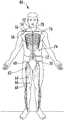
- FIG. 1illustrates the location of various nerve blocks where the method and system of the present disclosure can be utilized to navigate medical professionals to a precise location in conjunction with ultrasound guidance;
- FIG. 2illustrates the location of the interscalene nerve block of FIG. 1 in more detail
- FIG. 3illustrates a perspective view of one embodiment of an imaging system according to the present disclosure
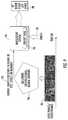
- FIG. 4illustrates a block diagram one of embodiment of a controller of an imaging system according to the present disclosure
- FIG. 5illustrates a schematic diagram of one embodiment of an ultrasound imaging system according to the present disclosure, particularly illustrating an ultrasound probe used in conjunction with a needle guide to facilitate navigation of a needle towards a target nerve of a patient;
- FIG. 6illustrates a plurality of real-time two-dimensional images collected from an anatomical region surrounding a target anatomical object of interest using the system and method of the present disclosure, where the anatomical object of interest, additional anatomical objects, and landmarks in the scenes contained in the images can be identified and labeled;
- FIG. 7illustrates a dataset containing a plurality of two-dimensional sliced images, where the dataset is used to train a deep learning network, where the deep learning network is used to detect, identify, label, and map the anatomical object of interest, additional anatomical objects, and landmarks contained in the real-time ultrasound images of FIG. 6 ;
- FIG. 8illustrates a schematic diagram of a method for automatic detection and mapping of scenes from an anatomical region surrounding a target anatomical object of interest in order to provide directions to a user to locate the target anatomical object of interest during a medical procedure;
- FIG. 9illustrates a schematic diagram of a method for automatic detection and mapping of scenes from an anatomical region surrounding a target anatomical object of interest in order to provide directions to a user to locate the target anatomical object of interest during medical procedure using a recurrent convolutional neural network;
- FIG. 10illustrates a flow diagram of one embodiment of a method for automatic detection and mapping of scenes from an anatomical region surrounding a target anatomical object of interest in order to provide directions to a user to locate the target anatomical object of interest during a medical procedure;
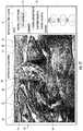
- FIG. 11illustrates a schematic diagram of a real-time ultrasound image of a scene of an anatomical region around an interscalene nerve block generated by an imaging system according to the present disclosure, where the anatomical objects and surrounding tissue of interest have been detected and identified with outlining and numbering;
- FIG. 12illustrates a schematic diagram of another embodiment of a real-time ultrasound image of a scene of an anatomical region around an interscalene nerve block generated by an imaging system according to the present disclosure, where the anatomical objects and surrounding tissue of interest have been detected and identified with outlining;
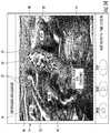
- FIG. 13illustrates a schematic diagram of yet another embodiment of a real-time ultrasound image of a scene of an anatomical region around an interscalene nerve block generated by an imaging system according to the present disclosure, where the anatomical objects and surrounding tissue of interest have been detected and identified with shading, outlining, and labeling;
- FIG. 14illustrates a schematic diagram of one more embodiment of a real-time ultrasound image of a scene of an anatomical region around an interscalene nerve block generated by an imaging system according to the present disclosure, where the anatomical objects and surrounding tissue of interest have been detected and identified with shading, outlining, and labeling.
- the present disclosureis directed to a system and method for providing navigational directions to a user (e.g., medical professional) to locate a target anatomical object during a medical procedure via a medical imaging system.
- the methodincludes selecting an anatomical region surrounding the object; generating a plurality of real-time two-dimensional images of scenes from the anatomical region and providing the plurality of images to a controller; developing and training a deep learning network to automatically detect and identify the scenes from the anatomical region; automatically mapping each of the plurality of images from the anatomical region based on a relative spatial location and a relative temporal location of each of the identified scenes in the anatomical region via the deep learning network; and providing directions to the user to locate the object or to reach the object with a surgical instrument (e.g., needle guide assembly, catheter, needle, scalpel, knife, probe, etc.) during the medical procedure based on the relative spatial and temporal locations of each of the identified scenes.
- a surgical instrumente.g., needle guide assembly, catheter, needle
- the present disclosureis directed to an imaging system and method for providing navigational directions to a user (e.g., medical professional) to locate or reach a target nerve of interest to deliver a nerve block to a patient using a plurality of real-time two-dimensional images of scenes from an anatomical region surrounding the target nerve generated by the imaging system, such as an ultrasound imaging system.
- the target nervecan be associated with the delivery of a nerve block to a patient 80 .
- nerve blocks contemplated by the present disclosureinclude an interscalene nerve block 52 , a supraclavicular nerve block 54 , an infraclavicular nerve block 56 , an axillary nerve block 58 , a femoral nerve block 60 , a sciatic nerve block 62 , an adductor canal nerve block 64 , a popliteal nerve block 66 , a saphenous nerve block 68 , a fascia iliaca nerve block 70 , a thoraco lumbar paravertebral nerve block 72 , a transversus abdominus plane (TAP) nerve block 74 , an intercostal nerve block 76 , a thoracic paravertebral nerve block 78 , and the like.
- TAPabdominus plane
- the anatomical regionincludes cricoid cartilage 29 , the internal jugular vein 31 , the external jugular vein 33 , the brachial plexus 34 , the sternocleidomastoid muscle 36 , the anterior scalene muscle 37 , the middle scalene muscle 38 , and the posterior scalene muscle 41 .
- the various anatomical objects or structures discussed abovecan be detected, identified/labeled, and mapped as discussed in more detail below so that a medical professional can be provided with directions to quickly and accurately insert a needle 45 into the target nerve 49 at needle insertion site 47 to deliver an anesthetic, resulting in an interscalene nerve block 52 .
- an imaging system 10configured to receive and organize a plurality of individual images 14 generated by the imaging system 10 in real-time is shown.
- the imaging system 10may correspond to an ultrasound imaging system (as shown), a computer tomography (CT) scanner, a magnetic resonance imaging (MRI) scanner, or any other suitable imaging system that can benefit from the present technology.
- CTcomputer tomography
- MRImagnetic resonance imaging
- the imaging system 10can include a controller 17 configured to receive and organize the plurality of images 14 generated by the imaging system 10 .
- the controller 17generally includes one or more processor(s) 16 and associated memory device(s) 18 configured to perform a variety of computer-implemented functions (e.g., performing the methods and the like and storing relevant data as disclosed herein), as well as a user display 20 .
- the processor 16can be configured to detect, identify, and map a plurality of scenes 12 contained within each image 14 generated by the imaging system 10 from a plurality of real-time two-dimensional ultrasound images 46 is shown.
- the imaging system 10can include a user interface 22 , such as a computer and/or keyboard, configured to assist a user in generating and/or manipulating the plurality of scenes 12 contained within each individual image 14 .
- the controller 17may also include a communications module 24 to facilitate communications between the controller 17 and the various components of the imaging system 10 , e.g. any of the components of FIGS. 3 and 4 .
- the communications module 24may include a sensor interface 26 (e.g., one or more analog-to-digital converters) to permit signals transmitted from one or more imaging system probes 28 (e.g., the ultrasound probe) to be converted into signals that can be understood and processed by the controller 17 and/or processor(s) 16 .
- the probe 28may be communicatively coupled to the communications module 24 using any suitable means.
- the probe 28may be coupled to the sensor interface 26 via a wired connection.
- the probe 28may be coupled to the sensor interface 26 via a wireless connection, such as by using any suitable wireless communications protocol known in the art.
- the controller 17may be configured to receive one or more signals from the probe 28 .
- controllerrefers not only to integrated circuits referred to in the art as being included in a computer, but also refers to a microcontroller, a microcomputer, a programmable logic controller (PLC), an application specific integrated circuit, a field-programmable gate array (FPGA), and other programmable circuits.
- PLCprogrammable logic controller
- FPGAfield-programmable gate array
- the controller 17is also configured to compute advanced control algorithms and communicate to a variety of Ethernet or serial-based protocols (Modbus, OPC, CAN, etc.).
- the controller 17may communicate with a server through the Internet for cloud computing in order to reduce the computation time and burden on the local device.
- the memory device(s) 18may generally comprise memory element(s) including, but not limited to, computer readable medium (e.g., random access memory (RAM)), computer readable non-volatile medium (e.g., a flash memory), a floppy disk, a compact disc-read only memory (CD-ROM), a magneto-optical disk (MOD), a digital versatile disc (DVD) and/or other suitable memory elements.
- RAMrandom access memory
- computer readable non-volatile mediume.g., a flash memory
- CD-ROMcompact disc-read only memory
- MODmagneto-optical disk
- DVDdigital versatile disc
- Such memory device(s) 18may generally be configured to store suitable computer-readable instructions that, when implemented by the controller 17 , configure the processor(s) 16 to perform the various functions as described herein.
- the probe 28(e.g., ultrasound probe) of the imaging system 10 can include a transducer housing 27 and a transducer transmitter 23 mounted therein.
- the transducer transmitter 23is configured to emit and/or receive ultrasound beams.
- the transducer transmitter 16may be configured within the internal cavity (not numbered) such that the transducer transmitter 16 is configured to scan an anatomical region surrounding a target anatomical object 149 (e.g., target nerve) of a patient.
- the imaging system 10may also include an instrument 145 that is used during any suitable medical procedure, where the instrument 145 is coupled to the probe 28 via the controller 17 in any suitable manner (e.g., wireless, wired, etc.), where the location of the instrument 145 can be determined via the methods described herein.
- the instrument 145can be a needle guide assembly 82 communicatively coupled to the ultrasound probe 28 via the controller 17 , where the controller 17 can be configured to locate the needle guide assembly 82 as it is being moved towards the target anatomical object 149 (e.g., the target nerve) to deliver an anesthetic via a needle 45 .
- the target anatomical object 149e.g., the target nerve
- any instrumentsuch as a scalpel, knife, laparoscopic or arthroscopic probe, etc. can be used instead of the needle guide assembly 82 depending on the procedure being performed by the medical professional.
- the needle guide assembly 82may include, at least, a needle 45 and a catheter 83 .
- the needle 45as well as the catheter 83 of the needle guide assembly 82 can be inserted through the skin 81 the patient 80 in any particular order or simultaneously.
- the ultrasound imaging system 10may include an over-the-needle (OTN) catheter assembly in which the catheter 83 is coaxially mounted over the needle 45 .
- the needle 45may be mounted over the catheter 83 .
- the needle 45may act as an introducer such that it places the catheter 83 at the target nerve 49 and is later removed.
- FIGS. 6-14schematic diagrams ( FIGS. 6-9 ) and a flow diagram ( FIG. 10 ) of one embodiment of a method 100 for the automatic detection, identification, and mapping of anatomical objects contained within a plurality of scenes 12 taken from a plurality of real-time two-dimensional images 46 generated by an imaging system 10 to provide directions to a user are illustrated, as are various embodiments of screen shots ( FIGS. 11-14 ) from the user display 20 illustrating an image 14 containing a scene 12 generated from one of the plurality of real-time two-dimensional images 46 when an ultrasound imaging system is used.
- the target anatomical object(s) of interest 30 and the surrounding additional anatomical objects 32 as described hereinmay include any anatomy structure and/or surrounding tissue of the anatomy structure of a patient. More specifically, as shown in the illustrated embodiments of FIGS. 11-14 , when a nerve block procedure is to be completed, and specifically when the nerve block procedure is an interscalene nerve block, the anatomical object of interest 30 that can be detected, identified, and mapped can be an interscalene brachial plexus (BP) 34 of the patient, which generally corresponds to the network of nerves running from the spine, formed by the anterior rami of the lower four cervical nerves and first thoracic nerve.
- BPinterscalene brachial plexus
- the brachial plexus 34passes through the cervicoaxillary canal in the neck, over the first rib, and into the axilla (i.e. the armpit region), where it innervates the upper limbs and some neck and shoulder muscles.
- the surrounding additional anatomical objects 32e.g., tissue
- the brachial plexus 34generally correspond to the sternocleidomastoid muscle (SM) 36 , the middle scalene muscle (MCM) 38 , the anterior scalene muscle (ASM) 40 , and/or similar.
- SMsternocleidomastoid muscle
- MCMmiddle scalene muscle
- ASManterior scalene muscle
- the system and method of the present disclosureprovides an improved method for detecting, identifying, and mapping the target anatomical object of interest 30 in the various scenes 12 captured in images 14 so that the anesthetic can be delivered quickly and accurately to block the nerve associated with the target anatomical object of interest 30 , whereby directions are provided to the user to navigate around the surrounding additional anatomical objects 32 , landmarks, tissue, etc.
- the system and method of the present disclosuremay be used for any variety of medical procedures involving any anatomy structure in addition to those relating to the brachial plexus 34 .
- the target anatomical object(s) of interest 30 and the surrounding additional anatomical objects 32 or tissuemay be from any anatomical region discussed above with respect to the nerve blocks described in FIG. 1 or from any other anatomical region around which a medical procedure is to be performed.
- the image 14 generated by the imaging system 10may include the scene 12 from the anatomical region surrounding the target anatomical object of interest 30 as well as an optional task bar 15 located adjacent thereto.
- the task bar 15may include other suitable control features such as open, start, and stop buttons as well as the date and time. In alternative embodiments, the task bar 15 may be omitted. It should also be understood that the image 14 may further include any other suitable control and/or display features and may be controlled via the user interface 22 or via touch-screen capabilities.
- the method of the present inventioninvolves generating a plurality of real-time two-dimensional sliced images 46 a , 46 b , 46 c , 46 d , 46 e , 46 f , 46 g , 46 h , 46 i , and 46 j that are collected from an anatomical region surrounding an anatomical object (e.g., target nerve) of interest 30 using the system of the present disclosure. Further, as shown in FIG.
- a dataset 84 containing a plurality of two-dimensional sliced images 84 a , 84 b , 84 c , 84 d , 84 e , 84 f , 84 g , 84 h , 84 i , and 84 jcan be previously obtained, where the dataset 84 is used to train a deep learning network, where the deep learning network is used to detect and identify/label scenes from the anatomical region surrounding the target anatomical object, and then map each of the plurality of real-time two-dimensional images from the anatomical region surrounding the target anatomical object based on a relative spatial location and a relative temporal location of each of the identified scenes in the anatomical region contained in the real-time two-dimensional ultrasound images 46 a - j of FIG.
- the target anatomical object 30 or 149 and additional anatomical objects 32 and other landmarks/tissue (not shown) contained within scenes of the real-time two-dimensional ultrasound images 46can be automatically detected, identified, and tracked at block 48 , followed by mapping and continued tracking at block 50 , utilizing a deep learning network that has been trained to by the dataset of images 84 in order to provide continuous navigational tracking during any medical procedure being performed by a medical professional.
- a deep learning networkthat has been trained to by the dataset of images 84 in order to provide continuous navigational tracking during any medical procedure being performed by a medical professional.
- any number of real-time two-dimensional images 46 and/or images in the dataset 84can be obtained. For instance, up to 100,000, such as between about 5 and 50,000, such as between about 10 and about 10,000, or any other suitable number of images of different scenes can be utilized.
- the resulting mapped locationscan be used to provide a user with directions/continuous navigation tracking at block 51 to locate the target anatomical object of interest (e.g., target nerve) during a medical procedure (e.g., delivery of a nerve block).
- target anatomical object of intereste.g., target nerve
- the continuous navigation trackingcan be based on the use of a recurrent convolutional neural network 90 .
- the recurrent convolutional neural network 90can process real-time images 46 over a span of time 88 and can identify the major landmarks present in identified scenes from the images 46 , which can be output to the navigation system 94 in the forms of text, speech, numbers, etc.
- Using a recurrent convolutional neural network 90can ensure that a history of previously processed frames (such as the data set of images 84 ) is stored so that the temporal correlation of videos/images can be extracted for more accurate detection and tracking.
- the output 92 of the tracking systemcan be in the form of text, audio/speech, or assigned labels and numbers.
- the navigation system 94then receives the output 92 from the tracking system in order to determine the navigation system knows the current location of probe, instrument, etc. Based on the target anatomical object 149 and the current location of the probe 28 and/or instrument 145 , the navigation system 94 can use a pre-programmed lookup table 96 of landmarks to calculate the correct path toward the target anatomical object 149 . Then, the navigation system 94 it will provide guidance and directions 98 to the user such as moving the imaging probe 28 and/or instrument 145 to the right, left, up and down as well as changing angles. Such directions 98 can be provided in the form of text or arrows superimposed on the user display or can be in the form of audio/speech.
- the method 100generally includes selecting an anatomical region surrounding a target anatomical object (e.g., target nerve) of interest. Then, as shown at 104 , the method 100 includes generating a plurality of real-time two-dimensional images 46 of scenes 12 from the anatomical region of surrounding the target anatomical object of interest and providing the plurality of real-time two-dimensional images 12 to the controller 17 .
- a target anatomical objecte.g., target nerve
- the method 100also includes developing and training a deep learning network to automatically detect and identify scenes 12 from the anatomical region surrounding the target anatomical object (e.g., additional anatomical objects, landmarks, surrounding tissue, etc.) contained in the real-time two-dimensional ultrasound images 46 using a dataset of two-dimensional images 84 received from a plurality of patients, where the dataset of images 84 is generated by scanning and collecting, for each of the plurality of patients, scenes from a plurality of images from the anatomical region surrounding the target anatomical object of interest.
- the target anatomical objecte.g., additional anatomical objects, landmarks, surrounding tissue, etc.
- the target anatomical object, additional anatomical objects, landmarks, surrounding tissue, or a combination thereof from each scene 12 contained in the plurality of real-time two-dimensional images 46 for each patientcan be labeled or annotated to form a plurality of images 14 .
- the deep learning networkmay include one or more deep convolutional neural networks (CNNs), one or more recurrent neural networks, or any other suitable neural network configurations.
- CNNsdeep convolutional neural networks
- recurrent neural networksor any other suitable neural network configurations.
- deep convolutional neural networksgenerally refer to a type of feed-forward artificial neural network in which the connectivity pattern between its neurons is inspired by the organization of the animal visual cortex, whose individual neurons are arranged in such a way that they respond to overlapping regions tiling the visual field.
- recurrent neural networksgenerally refer to a class of artificial neural networks where connections between units form a directed cycle. Such connections create an internal state of the network which allows the network to exhibit dynamic temporal behavior.
- RNNscan use their internal memory to process arbitrary sequences of inputs. As such, RNNs can extract the correlation between the image frames in order to better identify and track anatomical objects in real time.
- the controller 17may use ground truth data to train and/or develop the deep neural network to automatically detect and identify the scenes 12 of the real-time two-dimensional images 46 containing the target anatomical object 30 or 149 , landmarks 42 , and/or additional anatomical objects (e.g., tissue) 32 .
- the controller 17may be configured to initially train the deep neural network to automatically detect and identify the scenes 12 containing the target anatomical object(s) 30 or 149 , additional anatomical objects 32 , landmarks 42 , etc. More specifically, in certain embodiments, the initial training may be completed while the controller 17 is offline. In another embodiment, the controller 17 may be configured to continuously train the deep neural network online to automatically detect the scenes 12 containing the target anatomical object(s) 30 or 149 , additional anatomical objects 32 , landmarks 42 , etc. after the initial training is complete.
- the controller 17may be configured for online learning to continuously train the deep neural network from newly captured data in the field to automatically detect the target anatomical object 30 or 149 , additional anatomical objects 32 , landmarks 42 , etc. present in the scene 12 by scanning and collecting a dataset of images 84 of the target anatomical object 30 or 149 , additional anatomical objects 32 , landmarks 42 , etc. from multiple patients.
- hundreds and/or thousands of imagesmay be scanned and collected from multiple patients and stored in the dataset of images 84 via the memory device(s) 18 .
- the dataset of images 84may be annotated based on user input to create the ground truth data.
- physiciansmay annotate and manually identify the dataset of images 84 based on expert knowledge to assist the deep learning network in detecting and identifying the target anatomical object(s) 30 , additional anatomical objects 32 , landmarks 42 , etc. in each image of the dataset.
- the ground truth data as described hereingenerally refers to information provided by direct observation of experts in the field as opposed to information provided by inference.
- the deep learning network of the present disclosureis configured to mimic a human brain during operation.
- the dataset of images 84can then be divided into a plurality of groups.
- the ground truth datamay be divided into at least two groups including a training dataset and a validation dataset.
- the controller 17is configured to utilize the training dataset to train the parameter space deep neural network. More specifically, in certain embodiments, the controller 17 may be configured to optimize a cost function to minimize an error between an output of the deep neural network and the ground truth data.
- the step of optimizing the cost function to minimize the errormay include utilizing a stochastic approximation, such as a stochastic gradient descent (SGD) algorithm, that iteratively processes portions of the ground truth data and adjusts one or more parameters of the deep neural network based on the error between the output of the deep neural network and the ground truth data.
- a stochastic gradient descentgenerally refers to a stochastic approximation of the gradient descent optimization method for minimizing an objective function that is written as a sum of differentiable functions.
- the controller 17may be configured to implement supervised learning to minimize the error between the output of the deep neural network and the ground truth data.
- supervised learninggenerally refers to the machine learning task of inferring a function from labeled training data.
- the cost functioncan be defined in different ways such as mean squared error, dice coefficient, categorical cross entropy, etc., and can be optimized using various methods including SGD and its variants such as Adam, Adadelta, Nestrov, etc.
- the processor(s) 16may implement further deep learning techniques, such as reinforcement learning to train a computer agent to detect anatomical objects in medical images, unsupervised learning to pre-train neural networks and cluster objects using unlabeled data, and/or any other techniques now known or later developed in the art. Such methods may require less training data and/or rely on a reward/punishment function such that the systems do not need to be specifically provided with labeled data.
- the method 100may also include, after optimizing the cost function, utilizing the deep learning network in real-time to automatically provide predictions on the validation data as well the newly captured data.
- the controller 17may be configured to compare the predictions with the ground truth data to ensure that the deep neural network is able to generalize. In other words, the controller 17 may be configured to ensure that the deep neural network can provide accurate predictions for cases falling outside of the training data.
- the method 100also includes automatically mapping each of the plurality of real-time two-dimensional ultrasound images 46 from the anatomical region surrounding the target anatomical object of interest based on the relative spatial location and the relative temporal of each of the identified scenes in the anatomical region.
- the mappingcan be based on the identified scenes from the tracking system and a lookup table that is programmed into the system, as discussed above with respect to FIG. 9 .
- the methodfurther includes providing directions to a user (e.g., medical professional) to locate the target anatomical object of interest (e.g., target nerve) during a medical procedure (e.g., delivery of a nerve block via, for instance, the needle 45 shown in FIG. 5 ), based on the relative spatial location and the relative temporal location of each of the scenes identified in the plurality of real-time two dimensional images 46 .
- the directionscan be provided to the user in annotated form on the user display 20 of the imaging system 10 as the user moves an instrument 145 (e.g., needle 45 in FIG. 2 ) towards the target anatomical object 149 (e.g., target nerve 49 in FIG.
- the probe 28simultaneously scans the anatomical region of interest and the imaging system 10 simultaneously generates the plurality of real-time two-dimensional images 46 .
- the directionscan be provided in the form of audio instructions, either alone or in combination with the annotated directions present on the user display 20 of the imaging system 10 .
- the medical professional/userscans an area near the target anatomical object 30 or 149 , its current location can be identified using the recurrent convolutional neural network (tracking system) described in FIG. 9 , and the path to reach the target anatomical object 30 or 149 (see, i.e., FIG. 5 ) can be calculated by the navigation system 94 of FIG. 9 .
- FIGS. 11-14when the medical procedure is a nerve block and the imaging system is an ultrasound imaging system, various images 14 obtained from the real-time ultrasound images 46 are shown, where the controller 17 has been configured to label the anatomical object(s) 30 , landmarks 42 , and/or surrounding tissue 32 on the image 14 . More specifically, in certain embodiments, the controller 17 may be configured to outline the target anatomical object 30 , additional anatomical objects 32 , etc. on the image 14 . For example, as shown in FIGS. 11 and 12 , the brachial plexus 34 (i.e., the target anatomical object 30 ) is outlined with a border having a first thickness or pattern.
- various surrounding additional anatomical objects/tissues 32can be outlined with a border having a second thickness that different from than the first thickness or pattern that is used to outline the brachial plexus 34 .
- a usercan easily identify and distinguish the target anatomical object(s) 30 of interest from the additional anatomical objects/tissue 32 in the anatomical region.
- the controller 17can be configured to overlay a descriptive label atop the target anatomical object(s) 30 and/or surrounding additional anatomical objects/tissue 32 on the real-time two-dimensional ultrasound image 46 to obtain various annotated images 14 .
- the surrounding anatomical objects/tissue 32may be numbered and labeled as landmarks 42 (e.g. on the right side of the image 14 ) for easy identification via a physician.
- the surrounding anatomical objects/tissue 32may be identified and distinguished by line type and identified as landmarks 42 particularly illustrating a location within the body of the patient.
- FIG. 11the surrounding anatomical objects/tissue 32 may be identified and distinguished by line type and identified as landmarks 42 particularly illustrating a location within the body of the patient.
- the surrounding anatomical objects/tissue 32may be shaded and labeled using a descriptive medical name.
- the target anatomical object(s) 30may also be further defined and/or segmented. As such, in the case of the brachial plexus 34 , a user can easily identify separate nerves or nerve bundles during a nerve block procedure.
- the controller 17may also be configured to determine a confidence level 44 of the target anatomical object 30 and/or the surrounding anatomical objects/tissue 32 .
- the confidence level 44 of the location of the brachial plexus 34is located on the task bar 15 of the image 14 .
- the confidence level 44 of the location of the brachial plexus 34may be located within the identified scene 12 of the image 14 , e.g. adjacent to the target anatomical object 30 .
Landscapes
- Health & Medical Sciences (AREA)
- Life Sciences & Earth Sciences (AREA)
- Engineering & Computer Science (AREA)
- Physics & Mathematics (AREA)
- Surgery (AREA)
- Nuclear Medicine, Radiotherapy & Molecular Imaging (AREA)
- Biomedical Technology (AREA)
- Medical Informatics (AREA)
- Molecular Biology (AREA)
- General Health & Medical Sciences (AREA)
- Heart & Thoracic Surgery (AREA)
- Animal Behavior & Ethology (AREA)
- Public Health (AREA)
- Veterinary Medicine (AREA)
- Pathology (AREA)
- Biophysics (AREA)
- Theoretical Computer Science (AREA)
- Radiology & Medical Imaging (AREA)
- General Physics & Mathematics (AREA)
- High Energy & Nuclear Physics (AREA)
- Computer Vision & Pattern Recognition (AREA)
- Data Mining & Analysis (AREA)
- Pulmonology (AREA)
- Artificial Intelligence (AREA)
- Evolutionary Computation (AREA)
- Computing Systems (AREA)
- General Engineering & Computer Science (AREA)
- Mathematical Physics (AREA)
- Software Systems (AREA)
- Oral & Maxillofacial Surgery (AREA)
- Computational Linguistics (AREA)
- Optics & Photonics (AREA)
- Robotics (AREA)
- Ultra Sonic Daignosis Equipment (AREA)
- Measuring And Recording Apparatus For Diagnosis (AREA)
- Image Analysis (AREA)
- Apparatus For Radiation Diagnosis (AREA)
- Magnetic Resonance Imaging Apparatus (AREA)
Abstract
Description
Claims (25)
Priority Applications (1)
| Application Number | Priority Date | Filing Date | Title |
|---|---|---|---|
| US15/736,129US10657671B2 (en) | 2016-12-02 | 2017-06-29 | System and method for navigation to a target anatomical object in medical imaging-based procedures |
Applications Claiming Priority (3)
| Application Number | Priority Date | Filing Date | Title |
|---|---|---|---|
| US201662429150P | 2016-12-02 | 2016-12-02 | |
| PCT/US2017/039928WO2018101985A1 (en) | 2016-12-02 | 2017-06-29 | System and method for navigation to a target anatomical object in medical imaging-based procedures |
| US15/736,129US10657671B2 (en) | 2016-12-02 | 2017-06-29 | System and method for navigation to a target anatomical object in medical imaging-based procedures |
Publications (2)
| Publication Number | Publication Date |
|---|---|
| US20190355149A1 US20190355149A1 (en) | 2019-11-21 |
| US10657671B2true US10657671B2 (en) | 2020-05-19 |
Family
ID=59363227
Family Applications (1)
| Application Number | Title | Priority Date | Filing Date |
|---|---|---|---|
| US15/736,129ActiveUS10657671B2 (en) | 2016-12-02 | 2017-06-29 | System and method for navigation to a target anatomical object in medical imaging-based procedures |
Country Status (10)
| Country | Link |
|---|---|
| US (1) | US10657671B2 (en) |
| EP (1) | EP3549103B1 (en) |
| JP (1) | JP6796085B2 (en) |
| KR (2) | KR101886990B1 (en) |
| CN (1) | CN109074665B (en) |
| BR (1) | BR112018000197A2 (en) |
| CA (1) | CA2989159C (en) |
| MX (1) | MX379308B (en) |
| RU (1) | RU2017142603A (en) |
| WO (1) | WO2018101985A1 (en) |
Families Citing this family (55)
| Publication number | Priority date | Publication date | Assignee | Title |
|---|---|---|---|---|
| US11164679B2 (en) | 2017-06-20 | 2021-11-02 | Advinow, Inc. | Systems and methods for intelligent patient interface exam station |
| US12102397B2 (en)* | 2018-01-19 | 2024-10-01 | Verily Life Sciences Llc | Step-based system for providing surgical intraoperative cues |
| JP7125428B2 (en)* | 2018-01-31 | 2022-08-24 | 富士フイルム株式会社 | ULTRASOUND DIAGNOSTIC SYSTEM AND CONTROL METHOD OF ULTRASOUND DIAGNOSTIC SYSTEM |
| US10939806B2 (en)* | 2018-03-06 | 2021-03-09 | Advinow, Inc. | Systems and methods for optical medical instrument patient measurements |
| US11348688B2 (en)* | 2018-03-06 | 2022-05-31 | Advinow, Inc. | Systems and methods for audio medical instrument patient measurements |
| US20210240931A1 (en)* | 2018-04-30 | 2021-08-05 | Koninklijke Philips N.V. | Visual question answering using on-image annotations |
| US20200016396A1 (en)* | 2018-07-11 | 2020-01-16 | Synchron Australia Pty Limited | Systems and methods for improving placement of devices for neural stimulation |
| JP7134017B2 (en) | 2018-08-14 | 2022-09-09 | キヤノン株式会社 | Image processing device, image processing method, and program |
| KR102179045B1 (en)* | 2018-10-18 | 2020-11-16 | 한국외국어대학교 연구산학협력단 | Method for Learning Landmark Localization Model in 3D Medical Image |
| CN112955934B (en)* | 2018-11-01 | 2024-10-15 | 皇家飞利浦有限公司 | Identifying interventional devices in medical images |
| CN109589145A (en)* | 2018-12-28 | 2019-04-09 | 吴莹 | A kind of intelligence renal fibroblast control system |
| KR102659494B1 (en) | 2019-01-21 | 2024-04-23 | 삼성전자주식회사 | Electronic apparatus and control method thereof |
| US10970542B2 (en)* | 2019-02-22 | 2021-04-06 | Here Global B.V. | Scalable three dimensional object segmentation |
| EP3699925A1 (en)* | 2019-02-25 | 2020-08-26 | Koninklijke Philips N.V. | Camera assisted subject support configuration |
| CN113678167B (en)* | 2019-04-02 | 2025-08-12 | 皇家飞利浦有限公司 | Segmentation and view guidance in ultrasound imaging and associated devices, systems, and methods |
| US11707255B2 (en)* | 2019-04-02 | 2023-07-25 | Siemens Medical Solutions Usa, Inc. | Image-based probe positioning |
| WO2020213106A1 (en)* | 2019-04-17 | 2020-10-22 | Nec Corporation | Image processing apparatus, image processing method and non-transitoty computer readable medium |
| US20210045716A1 (en)* | 2019-08-13 | 2021-02-18 | GE Precision Healthcare LLC | Method and system for providing interaction with a visual artificial intelligence ultrasound image segmentation module |
| US12171592B2 (en)* | 2019-08-30 | 2024-12-24 | Avent, Inc. | System and method for identification, labeling, and tracking of a medical instrument |
| CN112446476B (en)* | 2019-09-04 | 2025-04-15 | 华为技术有限公司 | Neural network model compression method, device, storage medium and chip |
| US11024027B2 (en)* | 2019-09-13 | 2021-06-01 | Siemens Healthcare Gmbh | Manipulable object synthesis in 3D medical images with structured image decomposition |
| US12080021B2 (en)* | 2019-09-20 | 2024-09-03 | Brainlab Ag | Training a machine learning algorithm using digitally reconstructed radiographs |
| JP7427902B2 (en) | 2019-10-02 | 2024-02-06 | コニカミノルタ株式会社 | Ultrasonic image diagnostic training device, ultrasonic image diagnostic device, identification model training method, program, and ultrasonic diagnostic device |
| JP7432340B2 (en)* | 2019-11-07 | 2024-02-16 | 川崎重工業株式会社 | Surgical system and control method |
| US12186132B2 (en)* | 2019-11-21 | 2025-01-07 | Koninklijke Philips N.V. | Point-of-care ultrasound (POCUS) scan assistance and associated devices, systems, and methods |
| US20210177295A1 (en)* | 2019-12-11 | 2021-06-17 | GE Precision Healthcare LLC | Systems and methods for generating diagnostic scan parameters from calibration images |
| EP4213106A1 (en)* | 2019-12-19 | 2023-07-19 | Brainlab AG | Medical image analysis using machine learning and an anatomical vector |
| EP4084721B1 (en) | 2019-12-31 | 2025-10-01 | Auris Health, Inc. | Anatomical feature identification and targeting |
| CN115088024A (en) | 2020-01-16 | 2022-09-20 | 维萨国际服务协会 | System and computer-implemented method for character recognition in payment cards |
| EP3868303A1 (en)* | 2020-02-18 | 2021-08-25 | Koninklijke Philips N.V. | Ultrasound guidance method and system |
| EP3862969A1 (en)* | 2020-02-07 | 2021-08-11 | Siemens Healthcare GmbH | Orientation detection in medical image data |
| EP3881793A1 (en)* | 2020-03-17 | 2021-09-22 | CHU de NICE | Surgical instrument and computer-implemented method for determining the position and orientation of such surgical instrument |
| US11737663B2 (en) | 2020-03-30 | 2023-08-29 | Auris Health, Inc. | Target anatomical feature localization |
| CN111488985B (en)* | 2020-04-08 | 2023-11-14 | 华南理工大学 | Deep neural network model compression training methods, devices, equipment and media |
| EP4135566A4 (en)* | 2020-04-13 | 2024-05-15 | Kaliber Labs Inc. | SYSTEMS AND METHODS OF AI-ASSISTED SURGICAL INTERVENTIONS |
| DE102020204985A1 (en)* | 2020-04-21 | 2021-10-21 | Siemens Healthcare Gmbh | Control of a robotic moving medical object |
| US20210334955A1 (en)* | 2020-04-24 | 2021-10-28 | Nvidia Corporation | Image annotation using one or more neural networks |
| CN112001224B (en)* | 2020-07-02 | 2025-01-10 | 北京奥维视讯科技有限责任公司 | Video acquisition method and video acquisition system based on convolutional neural network |
| CN111839730B (en)* | 2020-07-07 | 2022-02-11 | 厦门大学附属翔安医院 | Photoacoustic imaging surgical navigation platform for guiding tumor resection |
| EP3967232A1 (en)* | 2020-09-10 | 2022-03-16 | Koninklijke Philips N.V. | Method for providing a source of secondary medical imaging |
| DE102020212086A1 (en)* | 2020-09-25 | 2022-03-31 | Siemens Healthcare Gmbh | Determining the quality of a positioning of an object introduced into a patient's body |
| WO2022080184A1 (en) | 2020-10-16 | 2022-04-21 | 富士フイルム株式会社 | Ultrasonic diagnostic device and display method for ultrasonic diagnostic device |
| US12361557B2 (en) | 2020-12-21 | 2025-07-15 | Medtronic Navigation, Inc. | Systems and methods for monitoring one or more anatomical elements |
| CN112766314B (en)* | 2020-12-31 | 2024-05-28 | 上海联影智能医疗科技有限公司 | Anatomical structure recognition method, electronic device, and storage medium |
| WO2022157759A1 (en)* | 2021-01-21 | 2022-07-28 | Epidutech Ltd. | Method for tracking a medical tool during a medical procedure using deep learning |
| CN112819724B (en)* | 2021-02-05 | 2024-06-28 | 广东电网有限责任公司广州供电局 | A Scanned Document Image Enhancement Method Based on CNN |
| EP4059435A1 (en)* | 2021-03-15 | 2022-09-21 | Koninklijke Philips N.V. | Patient preparation for medical imaging |
| WO2022221341A1 (en) | 2021-04-12 | 2022-10-20 | Chandra Jonelagadda | Systems and methods for using image analysis in superior capsule reconstruction |
| US12367261B1 (en)* | 2021-05-19 | 2025-07-22 | Nvidia Corporation | Extending supervision using machine learning |
| EP4360014A1 (en)* | 2021-06-22 | 2024-05-01 | Boston Scientific Scimed, Inc. | Systems and methods utilizing machine-learning for in vivo navigation |
| CN115990059A (en)* | 2021-10-20 | 2023-04-21 | 奥林巴斯株式会社 | Method of operating a medical navigation system for image-guided surgical procedures |
| CN114052795B (en)* | 2021-10-28 | 2023-11-07 | 南京航空航天大学 | Focus imaging and anti-false-prick therapeutic system combined with ultrasonic autonomous scanning |
| WO2023152530A2 (en)* | 2021-12-10 | 2023-08-17 | Mofaip, Llp | Multidimensional anatomic mapping, descriptions, visualizations, and translations |
| CN114840110B (en)* | 2022-03-17 | 2023-06-20 | 杭州未名信科科技有限公司 | A mixed reality-based puncture navigation interactive assistance method and device |
| CN118986403B (en)* | 2024-10-21 | 2025-01-14 | 广东和诚信息技术有限公司 | Remote ultrasonic detection method and system |
Citations (38)
| Publication number | Priority date | Publication date | Assignee | Title |
|---|---|---|---|---|
| US20030133611A1 (en) | 2000-05-09 | 2003-07-17 | Siemens Aktiengesellschaft | Method and device for determining an object in an image |
| US20030174881A1 (en) | 2002-03-15 | 2003-09-18 | Simard Patrice Y. | System and method facilitating pattern recognition |
| JP2005199403A (en) | 2004-01-16 | 2005-07-28 | Sony Corp | Emotion recognition device and method, emotion recognition method of robot device, learning method of robot device and robot device |
| JP2008017997A (en) | 2006-07-12 | 2008-01-31 | Hitachi Medical Corp | Surgery support navigation system |
| US20100010348A1 (en) | 2008-07-11 | 2010-01-14 | Menachem Halmann | Systems and methods for visualization of an ultrasound probe relative to an object |
| US7876934B2 (en) | 2004-11-08 | 2011-01-25 | Siemens Medical Solutions Usa, Inc. | Method of database-guided segmentation of anatomical structures having complex appearances |
| US20110182493A1 (en) | 2010-01-25 | 2011-07-28 | Martin Huber | Method and a system for image annotation |
| US20110188715A1 (en) | 2010-02-01 | 2011-08-04 | Microsoft Corporation | Automatic Identification of Image Features |
| US8073220B2 (en) | 2009-04-20 | 2011-12-06 | Siemens Aktiengesellschaft | Methods and systems for fully automatic segmentation of medical images |
| WO2013179188A1 (en) | 2012-05-31 | 2013-12-05 | Koninklijke Philips N.V. | Method and system for quantitative evaluation of image segmentation |
| US20130336553A1 (en) | 2010-08-13 | 2013-12-19 | Smith & Nephew, Inc. | Detection of anatomical landmarks |
| US20140129200A1 (en) | 2007-01-16 | 2014-05-08 | Simbionix Ltd. | Preoperative surgical simulation |
| US8867802B2 (en) | 2011-04-19 | 2014-10-21 | Microsoft Corporation | Automatic organ localization |
| US20140314290A1 (en) | 2013-04-22 | 2014-10-23 | Toshiba Medical Systems Corporation | Positioning anatomical landmarks in volume data sets |
| US20150148657A1 (en) | 2012-06-04 | 2015-05-28 | Tel Hashomer Medical Research Infrastructure And Services Ltd. | Ultrasonographic images processing |
| US20150164605A1 (en) | 2013-12-13 | 2015-06-18 | General Electric Company | Methods and systems for interventional imaging |
| US20150173701A1 (en) | 2012-07-24 | 2015-06-25 | Agfa Healthcare Nv | Method, apparatus and system for automated spine labeling |
| WO2015092582A1 (en) | 2013-12-20 | 2015-06-25 | Koninklijke Philips N.V. | Automatic ultrasound beam steering and needle artifact suppression |
| WO2015104607A1 (en) | 2014-01-07 | 2015-07-16 | Koninklijke Philips N.V. | Ultrasound imaging modes for automated real time quantification and analysis |
| WO2015109254A2 (en) | 2014-01-17 | 2015-07-23 | Morpheus Medical, Inc. | Apparatus, methods and articles for four dimensional (4d) flow magnetic resonance imaging |
| US20150265251A1 (en) | 2014-03-18 | 2015-09-24 | Samsung Electronics Co., Ltd. | Apparatus and method for visualizing anatomical elements in a medical image |
| US9153022B2 (en) | 2010-09-16 | 2015-10-06 | Mor Research Applications Ltd. | Method and system for analyzing craniofacial complex images |
| WO2015175806A1 (en) | 2014-05-16 | 2015-11-19 | The Trustees Of The University Of Pennsylvania | Applications of automatic anatomy recognition in medical tomographic imagery based on fuzzy anatomy models |
| WO2015191414A2 (en) | 2014-06-09 | 2015-12-17 | Siemens Corporation | Landmark detection with spatial and temporal constraints in medical imaging |
| US20160012604A1 (en) | 2014-07-11 | 2016-01-14 | Siemens Medical Solutions Usa, Inc. | Automatic background region selection for lesion delineation in medical images |
| US9256962B2 (en) | 2013-01-23 | 2016-02-09 | Orca Health Inc. | Personalizing medical conditions with augmented reality |
| US20160042511A1 (en) | 2013-03-15 | 2016-02-11 | Ventana Medical Systems, Inc. | Tissue Object-Based Machine Learning System for Automated Scoring of Digital Whole Slides |
| US20160042510A1 (en) | 2013-03-15 | 2016-02-11 | Stephanie Littell | Evaluating Electromagnetic Imagery By Comparing To Other Individuals' Imagery |
| US20160058422A1 (en) | 2014-09-01 | 2016-03-03 | Samsung Medison Co., Ltd. | Ultrasound diagnosis apparatus, ultrasound diagnosis method performed by the ultrasound diagnosis apparatus, and computer-readable storage medium having the ultrasound diagnosis method recorded thereon |
| US20160092748A1 (en) | 2014-09-30 | 2016-03-31 | Kabushiki Kaisha Toshiba | Medical data processing apparatus and method |
| US20160106321A1 (en) | 2013-10-17 | 2016-04-21 | Siemens Aktiengesellschaft | Method and System for Machine Learning Based Assessment of Fractional Flow Reserve |
| US20160125595A1 (en) | 2014-11-03 | 2016-05-05 | Algotec Systems Ltd. | Method for segmentation of the head-neck arteries, brain and skull in medical images |
| US20160174902A1 (en) | 2013-10-17 | 2016-06-23 | Siemens Aktiengesellschaft | Method and System for Anatomical Object Detection Using Marginal Space Deep Neural Networks |
| US9384413B2 (en) | 2013-09-13 | 2016-07-05 | Siemens Aktiengesellschaft | Method and device for automatic or semi-automatic segmentation of a 3D image data set |
| US20160287214A1 (en) | 2015-03-30 | 2016-10-06 | Siemens Medical Solutions Usa, Inc. | Three-dimensional volume of interest in ultrasound imaging |
| US20160328643A1 (en) | 2015-05-07 | 2016-11-10 | Siemens Aktiengesellschaft | Method and System for Approximating Deep Neural Networks for Anatomical Object Detection |
| US20170265943A1 (en)* | 2016-03-16 | 2017-09-21 | Gal Sela | Trajectory alignment system and methods |
| US20170265947A1 (en)* | 2016-03-16 | 2017-09-21 | Kelly Noel Dyer | Trajectory guidance alignment system and methods |
Family Cites Families (10)
| Publication number | Priority date | Publication date | Assignee | Title |
|---|---|---|---|---|
| JP3642591B2 (en)* | 1994-11-29 | 2005-04-27 | 株式会社日立メディコ | Image processing device |
| US8175362B2 (en)* | 2007-10-19 | 2012-05-08 | Boston Scientific Scimed, Inc. | Display of classifier output and confidence measure in an image |
| WO2011087807A2 (en) | 2009-12-22 | 2011-07-21 | Health Discovery Corporation | System and method for remote melanoma screening |
| US20130249917A1 (en)* | 2012-03-26 | 2013-09-26 | Microsoft Corporation | Profile data visualization |
| US9129362B2 (en)* | 2013-05-22 | 2015-09-08 | Siemens Aktiengesellschaft | Semantic navigation and lesion mapping from digital breast tomosynthesis |
| US9471987B2 (en)* | 2013-08-09 | 2016-10-18 | Siemens Healthcare Gmbh | Automatic planning for medical imaging |
| US9235781B2 (en)* | 2013-08-09 | 2016-01-12 | Kabushiki Kaisha Toshiba | Method of, and apparatus for, landmark location |
| US9990743B2 (en)* | 2014-03-27 | 2018-06-05 | Riverain Technologies Llc | Suppression of vascular structures in images |
| CN107636659B (en)* | 2015-05-11 | 2021-10-12 | 西门子保健有限责任公司 | Method and system for detecting landmarks in medical images using deep neural networks |
| CN105139454B (en)* | 2015-08-06 | 2018-01-19 | 北京工业大学 | The extraction method of liver three dimensional area of interest in a kind of three-dimensional CT image |
- 2017
- 2017-06-29BRBR112018000197Apatent/BR112018000197A2/ennot_activeIP Right Cessation
- 2017-06-29KRKR1020177035042Apatent/KR101886990B1/ennot_activeExpired - Fee Related
- 2017-06-29USUS15/736,129patent/US10657671B2/enactiveActive
- 2017-06-29WOPCT/US2017/039928patent/WO2018101985A1/ennot_activeCeased
- 2017-06-29CNCN201780002386.1Apatent/CN109074665B/enactiveActive
- 2017-06-29EPEP17740527.1Apatent/EP3549103B1/enactiveActive
- 2017-06-29JPJP2017564130Apatent/JP6796085B2/ennot_activeExpired - Fee Related
- 2017-06-29MXMX2017017142Apatent/MX379308B/enunknown
- 2017-06-29CACA2989159Apatent/CA2989159C/enactiveActive
- 2017-06-29RURU2017142603Apatent/RU2017142603A/ennot_activeApplication Discontinuation
- 2017-06-29KRKR1020187012260Apatent/KR101949114B1/ennot_activeExpired - Fee Related
Patent Citations (38)
| Publication number | Priority date | Publication date | Assignee | Title |
|---|---|---|---|---|
| US20030133611A1 (en) | 2000-05-09 | 2003-07-17 | Siemens Aktiengesellschaft | Method and device for determining an object in an image |
| US20030174881A1 (en) | 2002-03-15 | 2003-09-18 | Simard Patrice Y. | System and method facilitating pattern recognition |
| JP2005199403A (en) | 2004-01-16 | 2005-07-28 | Sony Corp | Emotion recognition device and method, emotion recognition method of robot device, learning method of robot device and robot device |
| US7876934B2 (en) | 2004-11-08 | 2011-01-25 | Siemens Medical Solutions Usa, Inc. | Method of database-guided segmentation of anatomical structures having complex appearances |
| JP2008017997A (en) | 2006-07-12 | 2008-01-31 | Hitachi Medical Corp | Surgery support navigation system |
| US20140129200A1 (en) | 2007-01-16 | 2014-05-08 | Simbionix Ltd. | Preoperative surgical simulation |
| US20100010348A1 (en) | 2008-07-11 | 2010-01-14 | Menachem Halmann | Systems and methods for visualization of an ultrasound probe relative to an object |
| US8073220B2 (en) | 2009-04-20 | 2011-12-06 | Siemens Aktiengesellschaft | Methods and systems for fully automatic segmentation of medical images |
| US20110182493A1 (en) | 2010-01-25 | 2011-07-28 | Martin Huber | Method and a system for image annotation |
| US20110188715A1 (en) | 2010-02-01 | 2011-08-04 | Microsoft Corporation | Automatic Identification of Image Features |
| US20130336553A1 (en) | 2010-08-13 | 2013-12-19 | Smith & Nephew, Inc. | Detection of anatomical landmarks |
| US9153022B2 (en) | 2010-09-16 | 2015-10-06 | Mor Research Applications Ltd. | Method and system for analyzing craniofacial complex images |
| US8867802B2 (en) | 2011-04-19 | 2014-10-21 | Microsoft Corporation | Automatic organ localization |
| WO2013179188A1 (en) | 2012-05-31 | 2013-12-05 | Koninklijke Philips N.V. | Method and system for quantitative evaluation of image segmentation |
| US20150148657A1 (en) | 2012-06-04 | 2015-05-28 | Tel Hashomer Medical Research Infrastructure And Services Ltd. | Ultrasonographic images processing |
| US20150173701A1 (en) | 2012-07-24 | 2015-06-25 | Agfa Healthcare Nv | Method, apparatus and system for automated spine labeling |
| US9256962B2 (en) | 2013-01-23 | 2016-02-09 | Orca Health Inc. | Personalizing medical conditions with augmented reality |
| US20160042510A1 (en) | 2013-03-15 | 2016-02-11 | Stephanie Littell | Evaluating Electromagnetic Imagery By Comparing To Other Individuals' Imagery |
| US20160042511A1 (en) | 2013-03-15 | 2016-02-11 | Ventana Medical Systems, Inc. | Tissue Object-Based Machine Learning System for Automated Scoring of Digital Whole Slides |
| US20140314290A1 (en) | 2013-04-22 | 2014-10-23 | Toshiba Medical Systems Corporation | Positioning anatomical landmarks in volume data sets |
| US9384413B2 (en) | 2013-09-13 | 2016-07-05 | Siemens Aktiengesellschaft | Method and device for automatic or semi-automatic segmentation of a 3D image data set |
| US20160106321A1 (en) | 2013-10-17 | 2016-04-21 | Siemens Aktiengesellschaft | Method and System for Machine Learning Based Assessment of Fractional Flow Reserve |
| US20160174902A1 (en) | 2013-10-17 | 2016-06-23 | Siemens Aktiengesellschaft | Method and System for Anatomical Object Detection Using Marginal Space Deep Neural Networks |
| US20150164605A1 (en) | 2013-12-13 | 2015-06-18 | General Electric Company | Methods and systems for interventional imaging |
| WO2015092582A1 (en) | 2013-12-20 | 2015-06-25 | Koninklijke Philips N.V. | Automatic ultrasound beam steering and needle artifact suppression |
| WO2015104607A1 (en) | 2014-01-07 | 2015-07-16 | Koninklijke Philips N.V. | Ultrasound imaging modes for automated real time quantification and analysis |
| WO2015109254A2 (en) | 2014-01-17 | 2015-07-23 | Morpheus Medical, Inc. | Apparatus, methods and articles for four dimensional (4d) flow magnetic resonance imaging |
| US20150265251A1 (en) | 2014-03-18 | 2015-09-24 | Samsung Electronics Co., Ltd. | Apparatus and method for visualizing anatomical elements in a medical image |
| WO2015175806A1 (en) | 2014-05-16 | 2015-11-19 | The Trustees Of The University Of Pennsylvania | Applications of automatic anatomy recognition in medical tomographic imagery based on fuzzy anatomy models |
| WO2015191414A2 (en) | 2014-06-09 | 2015-12-17 | Siemens Corporation | Landmark detection with spatial and temporal constraints in medical imaging |
| US20160012604A1 (en) | 2014-07-11 | 2016-01-14 | Siemens Medical Solutions Usa, Inc. | Automatic background region selection for lesion delineation in medical images |
| US20160058422A1 (en) | 2014-09-01 | 2016-03-03 | Samsung Medison Co., Ltd. | Ultrasound diagnosis apparatus, ultrasound diagnosis method performed by the ultrasound diagnosis apparatus, and computer-readable storage medium having the ultrasound diagnosis method recorded thereon |
| US20160092748A1 (en) | 2014-09-30 | 2016-03-31 | Kabushiki Kaisha Toshiba | Medical data processing apparatus and method |
| US20160125595A1 (en) | 2014-11-03 | 2016-05-05 | Algotec Systems Ltd. | Method for segmentation of the head-neck arteries, brain and skull in medical images |
| US20160287214A1 (en) | 2015-03-30 | 2016-10-06 | Siemens Medical Solutions Usa, Inc. | Three-dimensional volume of interest in ultrasound imaging |
| US20160328643A1 (en) | 2015-05-07 | 2016-11-10 | Siemens Aktiengesellschaft | Method and System for Approximating Deep Neural Networks for Anatomical Object Detection |
| US20170265943A1 (en)* | 2016-03-16 | 2017-09-21 | Gal Sela | Trajectory alignment system and methods |
| US20170265947A1 (en)* | 2016-03-16 | 2017-09-21 | Kelly Noel Dyer | Trajectory guidance alignment system and methods |
Non-Patent Citations (3)
| Title |
|---|
| Hadjerci et al., "On-line Learning Dynamic Models for Nerve Detection in Ultrasound Videos", 2016 IEEE International Conference on Image Processing, Sep. 25, 2016, pp. 131-135. |
| International Search Report for PCT/US2017/039928, dated Oct. 10, 2017, 13 pages. |
| Reddy D. Manikanta, "On segmentation of Nerve Structures in Ultrasound Images", retrieved from the Internet: https://manikantareddvd.github.io/posts/2016/11/16/ultrasound-nerve-segmentations, Nov. 16, 2016, pp. 1-27. |
Also Published As
| Publication number | Publication date |
|---|---|
| BR112018000197A2 (en) | 2018-09-11 |
| CA2989159C (en) | 2021-12-28 |
| KR101886990B1 (en) | 2018-08-08 |
| CN109074665B (en) | 2022-01-11 |
| KR101949114B1 (en) | 2019-02-15 |
| CA2989159A1 (en) | 2018-03-05 |
| MX2017017142A (en) | 2018-11-09 |
| WO2018101985A1 (en) | 2018-06-07 |
| EP3549103B1 (en) | 2021-08-04 |
| CN109074665A (en) | 2018-12-21 |
| EP3549103A1 (en) | 2019-10-09 |
| RU2017142603A3 (en) | 2019-08-07 |
| JP6796085B2 (en) | 2020-12-02 |
| RU2017142603A (en) | 2019-08-07 |
| US20190355149A1 (en) | 2019-11-21 |
| JP2019508072A (en) | 2019-03-28 |
| KR20180116226A (en) | 2018-10-24 |
| MX379308B (en) | 2025-03-11 |
Similar Documents
| Publication | Publication Date | Title |
|---|---|---|
| US10657671B2 (en) | System and method for navigation to a target anatomical object in medical imaging-based procedures | |
| US12171592B2 (en) | System and method for identification, labeling, and tracking of a medical instrument | |
| AU2018214141B2 (en) | System and method for navigation to a target anatomical object in medical imaging-based procedures | |
| US20230044620A1 (en) | Algorithm-based methods for predicting and/or detecting a clinical condition related to insertion of a medical instrument toward an internal target | |
| AU2017292642B2 (en) | System and method for automatic detection, localization, and semantic segmentation of anatomical objects | |
| CN111340859B (en) | Method for image registration, learning device and medical imaging device | |
| CN113966204B (en) | Methods for automatic trajectory planning for medical interventions | |
| US20200029941A1 (en) | Articulating Arm for Analyzing Anatomical Objects Using Deep Learning Networks | |
| CN120641945A (en) | Computer-implemented method, apparatus, system and computer program product for processing anatomical imaging data | |
| WO2022254436A1 (en) | Closed-loop steering of a medical instrument toward a moving target | |
| CN117836776A (en) | Imaging during medical procedures | |
| US11766234B2 (en) | System and method for identifying and navigating anatomical objects using deep learning networks | |
| CN113876420B (en) | Path planning method, system, device and medium for planning surgical path | |
| Glisson | Comparison and assessment of semiautomatic image segmentation in computed tomography scans of the kidney. |
Legal Events
| Date | Code | Title | Description |
|---|---|---|---|
| AS | Assignment | Owner name:AVENT, INC., GEORGIA Free format text:ASSIGNMENT OF ASSIGNORS INTEREST;ASSIGNORS:AVENDI, MICHAEL R.;DUFFY, SHANE A.;HSU, KENNETH C.;SIGNING DATES FROM 20161123 TO 20161128;REEL/FRAME:044387/0585 | |
| FEPP | Fee payment procedure | Free format text:ENTITY STATUS SET TO UNDISCOUNTED (ORIGINAL EVENT CODE: BIG.); ENTITY STATUS OF PATENT OWNER: LARGE ENTITY | |
| AS | Assignment | Owner name:CITIBANK, N.A., NEW YORK Free format text:SECURITY INTEREST;ASSIGNORS:COOLSYSTEMS, INC.;AVENT, INC.;REEL/FRAME:048117/0410 Effective date:20181228 | |
| STPP | Information on status: patent application and granting procedure in general | Free format text:RESPONSE TO NON-FINAL OFFICE ACTION ENTERED AND FORWARDED TO EXAMINER | |
| STPP | Information on status: patent application and granting procedure in general | Free format text:NOTICE OF ALLOWANCE MAILED -- APPLICATION RECEIVED IN OFFICE OF PUBLICATIONS | |
| STPP | Information on status: patent application and granting procedure in general | Free format text:PUBLICATIONS -- ISSUE FEE PAYMENT VERIFIED | |
| STCF | Information on status: patent grant | Free format text:PATENTED CASE | |
| AS | Assignment | Owner name:JPMORGAN CHASE BANK, N.A., AS ADMINISTRATIVE AGENT, ILLINOIS Free format text:SECURITY INTEREST;ASSIGNOR:AVENT, INC.;REEL/FRAME:060441/0445 Effective date:20220624 | |
| AS | Assignment | Owner name:AVANOS MEDICAL SALES, LLC, GEORGIA Free format text:RELEASE BY SECURED PARTY;ASSIGNOR:CITIBANK, N.A.;REEL/FRAME:060557/0062 Effective date:20220624 Owner name:AVENT, INC., GEORGIA Free format text:RELEASE BY SECURED PARTY;ASSIGNOR:CITIBANK, N.A.;REEL/FRAME:060557/0062 Effective date:20220624 | |
| MAFP | Maintenance fee payment | Free format text:PAYMENT OF MAINTENANCE FEE, 4TH YEAR, LARGE ENTITY (ORIGINAL EVENT CODE: M1551); ENTITY STATUS OF PATENT OWNER: LARGE ENTITY Year of fee payment:4 |