US10656650B2 - Method for guiding and controlling drone using information for controlling camera of drone - Google Patents
Method for guiding and controlling drone using information for controlling camera of droneDownload PDFInfo
- Publication number
- US10656650B2 US10656650B2US15/542,417US201615542417AUS10656650B2US 10656650 B2US10656650 B2US 10656650B2US 201615542417 AUS201615542417 AUS 201615542417AUS 10656650 B2US10656650 B2US 10656650B2
- Authority
- US
- United States
- Prior art keywords
- unmanned aerial
- camera
- zoom
- aerial system
- controlling
- Prior art date
- Legal status (The legal status is an assumption and is not a legal conclusion. Google has not performed a legal analysis and makes no representation as to the accuracy of the status listed.)
- Active - Reinstated, expires
Links
Images


Classifications
- G—PHYSICS
- G05—CONTROLLING; REGULATING
- G05D—SYSTEMS FOR CONTROLLING OR REGULATING NON-ELECTRIC VARIABLES
- G05D1/00—Control of position, course, altitude or attitude of land, water, air or space vehicles, e.g. using automatic pilots
- G05D1/20—Control system inputs
- G05D1/22—Command input arrangements
- G05D1/221—Remote-control arrangements
- G—PHYSICS
- G05—CONTROLLING; REGULATING
- G05D—SYSTEMS FOR CONTROLLING OR REGULATING NON-ELECTRIC VARIABLES
- G05D1/00—Control of position, course, altitude or attitude of land, water, air or space vehicles, e.g. using automatic pilots
- G05D1/0094—Control of position, course, altitude or attitude of land, water, air or space vehicles, e.g. using automatic pilots involving pointing a payload, e.g. camera, weapon, sensor, towards a fixed or moving target
- B—PERFORMING OPERATIONS; TRANSPORTING
- B64—AIRCRAFT; AVIATION; COSMONAUTICS
- B64C—AEROPLANES; HELICOPTERS
- B64C39/00—Aircraft not otherwise provided for
- B64C39/02—Aircraft not otherwise provided for characterised by special use
- B—PERFORMING OPERATIONS; TRANSPORTING
- B64—AIRCRAFT; AVIATION; COSMONAUTICS
- B64C—AEROPLANES; HELICOPTERS
- B64C39/00—Aircraft not otherwise provided for
- B64C39/02—Aircraft not otherwise provided for characterised by special use
- B64C39/024—Aircraft not otherwise provided for characterised by special use of the remote controlled vehicle type, i.e. RPV
- B—PERFORMING OPERATIONS; TRANSPORTING
- B64—AIRCRAFT; AVIATION; COSMONAUTICS
- B64D—EQUIPMENT FOR FITTING IN OR TO AIRCRAFT; FLIGHT SUITS; PARACHUTES; ARRANGEMENT OR MOUNTING OF POWER PLANTS OR PROPULSION TRANSMISSIONS IN AIRCRAFT
- B64D47/00—Equipment not otherwise provided for
- B64D47/08—Arrangements of cameras
- G—PHYSICS
- G05—CONTROLLING; REGULATING
- G05D—SYSTEMS FOR CONTROLLING OR REGULATING NON-ELECTRIC VARIABLES
- G05D1/00—Control of position, course, altitude or attitude of land, water, air or space vehicles, e.g. using automatic pilots
- G05D1/10—Simultaneous control of position or course in three dimensions
- G05D1/101—Simultaneous control of position or course in three dimensions specially adapted for aircraft
- G—PHYSICS
- G05—CONTROLLING; REGULATING
- G05D—SYSTEMS FOR CONTROLLING OR REGULATING NON-ELECTRIC VARIABLES
- G05D1/00—Control of position, course, altitude or attitude of land, water, air or space vehicles, e.g. using automatic pilots
- G05D1/12—Target-seeking control
- G—PHYSICS
- G05—CONTROLLING; REGULATING
- G05D—SYSTEMS FOR CONTROLLING OR REGULATING NON-ELECTRIC VARIABLES
- G05D1/00—Control of position, course, altitude or attitude of land, water, air or space vehicles, e.g. using automatic pilots
- G05D1/40—Control within particular dimensions
- G05D1/46—Control of position or course in three dimensions
- G—PHYSICS
- G05—CONTROLLING; REGULATING
- G05D—SYSTEMS FOR CONTROLLING OR REGULATING NON-ELECTRIC VARIABLES
- G05D1/00—Control of position, course, altitude or attitude of land, water, air or space vehicles, e.g. using automatic pilots
- G05D1/60—Intended control result
- G05D1/656—Interaction with payloads or external entities
- G—PHYSICS
- G08—SIGNALLING
- G08G—TRAFFIC CONTROL SYSTEMS
- G08G5/00—Traffic control systems for aircraft
- G08G5/50—Navigation or guidance aids
- G08G5/55—Navigation or guidance aids for a single aircraft
- H—ELECTRICITY
- H04—ELECTRIC COMMUNICATION TECHNIQUE
- H04N—PICTORIAL COMMUNICATION, e.g. TELEVISION
- H04N23/00—Cameras or camera modules comprising electronic image sensors; Control thereof
- H04N23/60—Control of cameras or camera modules
- H04N23/69—Control of means for changing angle of the field of view, e.g. optical zoom objectives or electronic zooming
- H04N5/23296—
- B—PERFORMING OPERATIONS; TRANSPORTING
- B60—VEHICLES IN GENERAL
- B60Y—INDEXING SCHEME RELATING TO ASPECTS CROSS-CUTTING VEHICLE TECHNOLOGY
- B60Y2200/00—Type of vehicle
- B60Y2200/50—Aeroplanes, Helicopters
- B60Y2200/51—Aeroplanes
- B64C2201/141—
- B—PERFORMING OPERATIONS; TRANSPORTING
- B64—AIRCRAFT; AVIATION; COSMONAUTICS
- B64U—UNMANNED AERIAL VEHICLES [UAV]; EQUIPMENT THEREFOR
- B64U2101/00—UAVs specially adapted for particular uses or applications
- B64U2101/30—UAVs specially adapted for particular uses or applications for imaging, photography or videography
- B—PERFORMING OPERATIONS; TRANSPORTING
- B64—AIRCRAFT; AVIATION; COSMONAUTICS
- B64U—UNMANNED AERIAL VEHICLES [UAV]; EQUIPMENT THEREFOR
- B64U2201/00—UAVs characterised by their flight controls
- B—PERFORMING OPERATIONS; TRANSPORTING
- B64—AIRCRAFT; AVIATION; COSMONAUTICS
- B64U—UNMANNED AERIAL VEHICLES [UAV]; EQUIPMENT THEREFOR
- B64U2201/00—UAVs characterised by their flight controls
- B64U2201/10—UAVs characterised by their flight controls autonomous, i.e. by navigating independently from ground or air stations, e.g. by using inertial navigation systems [INS]
- B—PERFORMING OPERATIONS; TRANSPORTING
- B64—AIRCRAFT; AVIATION; COSMONAUTICS
- B64U—UNMANNED AERIAL VEHICLES [UAV]; EQUIPMENT THEREFOR
- B64U2201/00—UAVs characterised by their flight controls
- B64U2201/20—Remote controls
- G—PHYSICS
- G05—CONTROLLING; REGULATING
- G05D—SYSTEMS FOR CONTROLLING OR REGULATING NON-ELECTRIC VARIABLES
- G05D2109/00—Types of controlled vehicles
- G05D2109/20—Aircraft, e.g. drones
- G—PHYSICS
- G08—SIGNALLING
- G08G—TRAFFIC CONTROL SYSTEMS
- G08G5/00—Traffic control systems for aircraft
- G08G5/50—Navigation or guidance aids
- G08G5/57—Navigation or guidance aids for unmanned aircraft
Definitions
- the present inventionrelates a method of guiding and controlling an unmanned aerial system based on camera control information of the unmanned aerial system, and more particularly to a method of guiding and controlling an unmanned aerial system based on camera control information of the unmanned aerial system, in which a camera controller is enough to control a mission flight of the unmanned aerial system, and the speed, elevation, flight path, etc. of the unmanned aerial system are automatically controlled when a camera is used to continuously track a specific target.
- an aerial system control command(an airline point, an elevation command, a speed command) is issued by the internal pilot, and a joystick command needed for camera driving and reconnaissance is issued by the sensor pilot.
- Such issued commandsare transmitted to a mounted flight-control computer and the mounted camera through a wireless data link.
- an object of the present inventionis to provide a method of guiding and controlling an unmanned aerial system based on camera control information of the unmanned aerial system, in which a camera controller is enough to control a mission flight of the unmanned aerial system, and the speed, elevation, flight path, etc. of the unmanned aerial system are automatically controlled when a camera is used to continuously track a specific target.
- a method of guiding and controlling an unmanned aerial system based on camera control information of the unmanned aerial systemcomprising the steps of: (a) controlling a vertical axis of the unmanned aerial system by controlling a zoom of a gimbal camera by a zoom controller of a camera control unit so as to control an elevation and speed of the unmanned aerial system with a corresponding camera control signal; and (b) controlling a horizontal axis of the unmanned aerial system by controlling an angle of the gimbal camera by an angle controller of the camera control unit.
- the method of guiding and controlling an unmanned aerial system based on camera control information of the unmanned aerial systemfurther includes: (a-1) by the zoom controller 120 of the camera control unit 100 , generating a zoom command signal to control the zoom of the gimbal camera 330 the zoom command signal; (a-2) by a flight control computer 310 of the unmanned aerial system 300 , comparing the zoom included in the command signal with an optical zoom; (a-3) by the flight control computer 310 of the unmanned aerial system 300 , comparing the zoom included in command signal with a digital zoom; (a-4) by the flight control computer 310 , calculating an elevation command signal by multiplying the zoom by a scale value and at the same time calculating a speed command signal if the zoom is greater than the digital zoom; and (a-5) by the flight control computer 310 , comparing an elevation included in the elevation command signal with an elevation limitation value, issuing a command of lowering the elevation if the elevation is greater than the elevation limitation value, and maintaining the current elevation command If the elevation is not greater
- the method of guiding and controlling an unmanned aerial system based on camera control information of the unmanned aerial systemfurther includes: (b-1) transmitting a camera control signal generated by an angle controller 110 of the camera control unit 100 to the unmanned aerial system 300 through wireless communication; (b-2) controlling the gimbal camera 330 by delivering the camera control signal received in the flight control computer 310 to the gimbal camera 330 ; (b-3) by the flight control computer 310 , calculating a center point (a target point), at which the center of the gimbal camera 300 looks, based on angle information of the gimbal camera 330 and a flight posture and location data measured by a navigation equipment 350 mounted to the unmanned aerial system 300 ; (b-4) by the flight control computer 310 , calculating an offset between the target and the center point; and (b-5) by the flight control computer 310 , inputting a new airway point based on the calculated offset to guiding and controlling logic so that the unmanned aerial system can continuously track a virtual airway point.
- the present inventionis applicable by just modifying software without changing a general system of an unmanned aerial system, has an advantage that a camera controller is enough to control a mission flight of the unmanned aerial system, and is improved in convenience and tracking performance since the speed, elevation, flight path, etc. of the unmanned aerial system are automatically controlled when a camera is used to continuously track a specific target.
- FIG. 1is a block diagram of a system for guiding and controlling an unmanned aerial system based on camera control information of the unmanned aerial system according to the present invention
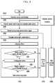
- FIG. 2is a flowchart of guiding and controlling an unmanned aerial system based on camera control information of the unmanned aerial system according to the present invention
- FIG. 3is a flowchart of controlling a longitudinal axis in the method of guiding and controlling an unmanned aerial system based on camera control information of the unmanned aerial system according to the present invention
- FIG. 4is a flowchart of controlling a lateral-directional axis in the method of guiding and controlling an unmanned aerial system based on camera control information of the unmanned aerial system according to the present invention
- FIG. 5illustrates an offset between a target and a center point
- FIG. 6is a geometrical relationship between an aerial system and a target
- FIG. 7is a view for explaining an equation for a posture limitation value.
- FIG. 1is a block diagram of a system for guiding and controlling an unmanned aerial system based on camera control information of the unmanned aerial system according to the present invention
- a system for guiding and controlling an unmanned aerial system based on camera control information of the unmanned aerial systemincludes a camera control unit 100 having an angle controller 110 and a zoom controller 120 ; ground control equipment 200 ; and an unmanned aerial system 300 having a flight control computer 310 , a control surface 320 , a gimbal camera 330 , an engine 340 , and navigation equipment 350 .
- a control method based on the system for guiding and controlling an unmanned aerial system based on camera control information of the unmanned aerial systemincludes the steps of controlling a longitudinal axis of the unmanned aerial system by controlling a zoom of the gimbal camera 330 by the zoom controller 120 of the camera control unit 100 so as to control the altitude and speed of the unmanned aerial system (S 100 ); and controlling a lateral-directional axis of the unmanned aerial system by controlling an angle of the gimbal camera 330 by the angle controller 110 of the camera control unit 100 (S 200 ).
- step S 100 of controlling the longitudinal axis of the unmanned aerial systemwill be described in detail with reference to FIG. 3 .
- a zoom command signalis generated to control the zoom of the gimbal camera 330 through the zoom controller 120 of the camera control unit 100 (S 110 ).
- the flight control computer 310determines whether the zoom included in command signal is greater than an optical zoom (S 120 ), determines whether the zoom is greater than a digital zoom (S 130 ) if it is determined in the step S 120 that the zoom is greater than the optical zoom, calculates an altitude command signal by multiplying the zoom by a scale value (S 140 ) and at the same time calculates a speed command signal (S 140 - 1 ) if it is determined in the step S 130 that the zoom is greater than the digital zoom.
- the flight control computer 310issues a command of the optical zoom (S 120 ′) if it is determined in the step S 120 that the zoom is not greater than the optical zoom S 120 .
- the flight control computer 310issues a command of the digital zoom (S 130 ′) if it is determined in the step S 130 that the zoom is not greater than the digital zoom S 130 .
- the flight control computer 310determines whether an elevation included in the altitude command signal is greater than an altitude limitation value (S 150 ), and issues a command of lowering the altitude (S 160 ) if the altitude is greater than the altitude limitation value.
- the flight control computer 310maintains the current altitude command (S 150 ′).
- the flight control computer 310issues a speed-up command or a speed-down command based on comparison with the speed limitation value (S 140 - 2 ).
- step S 200 of controlling the lateral-directional axis of the unmanned aerial systemwill be described in detail with reference to FIG. 4 .
- FIG. 4is a flowchart of controlling a lateral-directional axis in the method of guiding and controlling an unmanned aerial system based on camera control information of the unmanned aerial system according to the present invention.
- a camera control signal for controlling the lateral-directional axis of the unmanned aerial system and a camera control signal for controlling the longitudinal axis of the unmanned aerial systemare generated through the angle controller 110 and the zoom controller 120 of the camera control unit 100 (S 210 ).
- the camera control signals generated by the camera control unit 100are transmitted to the unmanned aerial system 300 by the ground control equipment 200 through wireless communication (S 220 ).
- the flight control computer 310 of the unmanned aerial system 300receives the camera control signals and delivers them to the gimbal camera 330 , thereby controlling the gimbal camera 330 (S 230 ).
- the flight control computer 310reflects such a changed value on an aerial system posture limitation value, and thus limits an autopilot posture so that the target can come into the FOV without getting out of a view angle when the aerial system operates.
- the flight control computer 310calculates the posture limitation value ( ⁇ limit) of the aerial system by subtracting the angle of camera FOV ( ⁇ FOV) from the angle ( ⁇ Target) between the gimbal camera 330 and the target.
- the flight control computer 310calculates the center point (i.e. the target point), at which the center of the gimbal camera 330 targets, based on the camera gimbal angle information output from the gimbal camera 330 and a flight altitude and location data measured by the navigation equipment 350 mounted to the unmanned aerial system 300 as the unmanned aerial system 300 flies, under control of the gimbal camera 330 (S 240 ).
- step S 240the center point or the target point is calculated as follows.
- R tis a distance from the center of the gimbal to the target point
- P cg I[X cg I Y cg I Z cg I ] T is a position of center of gravity in the unmanned aerial system
- P g cg[X g cg Y g cg Z g cg ] T is a position of the gimbal from the center of gravity of the unmanned aerial system.
- Equation 1will be described in more detail with reference to FIG. 6 showing a geometrical relationship between an aerial system and a target.
- a position (P t I ) of the target in an inertial coordinate systemis equal to the sum from the position vector ( ⁇ right arrow over (P) ⁇ cg I ) at the center of gravity of the aerial system to the position vector ( ⁇ right arrow over (P) ⁇ t g ) of the gimbal.
- the vector from the center of gravity of the aerial system to the targetmay be converted into reference coordinates for the center of gravity of the aerial system and then converted into geocentric coordinates, based on a relative distance vector.
- the firstis an inertial coordinate system (Inertial Frame) with respect to the center of the earth
- the secondis a body coordinate system (Body Frame) with respect to the center of gravity of the unmanned aerial system
- the thirdis a gimbal coordinate system (Gimbal Frame) with respect to the mission equipment.
- C ⁇is cos( ⁇ )
- S ⁇is sin( ⁇ ).
- 0is a pitch posture (angle)
- ⁇is a roll posture (angle)
- ⁇is a heading (angle).
- This distance (R t )is calculated as follows.
- Equation 1is developed by substations of [Equation 2] and [Equation 3] as follows.
- R tis obtained as follows.
- R tZ cg I - ( - S ⁇ ⁇ x g cg + S ⁇ ⁇ C ⁇ ⁇ y g cg + C ⁇ ⁇ ⁇ C ⁇ z g cg ) S ⁇ ⁇ C ⁇ ⁇ ⁇ g ⁇ C ⁇ ⁇ g - S ⁇ ⁇ C
- the flight control computer 310calculates an offset between the target and the center point as shown in FIG. 5 (S 250 ).
- the flight control computer 310calculates an easting offset and northing offset between the center point and the target.
- the flight control computer 310inputs a new airway point to guiding and controlling logic in consideration of the offset calculated in the step S 250 , so that the unmanned aerial system 300 can continuously track a virtual airway point (S 260 ).
- the flight control computer 310performs the steps of comparing a relative distance between the unmanned aerial system 300 and the target with a guiding decision distance (S 261 ), performing turning guide control if the guiding decision distance is longer than the relative distance (S 262 ), comparing the relative distance and a turning decision distance (S 263 ), and repetitively performing the turning guide control if the turning decision distance is longer than the relative distance (S 262 ).
- the flight control computer 310repetitively performs the steps following the step S 240 to thereby perform airway-point guide control (S 270 ).
Landscapes
- Engineering & Computer Science (AREA)
- Aviation & Aerospace Engineering (AREA)
- Physics & Mathematics (AREA)
- General Physics & Mathematics (AREA)
- Radar, Positioning & Navigation (AREA)
- Remote Sensing (AREA)
- Automation & Control Theory (AREA)
- Multimedia (AREA)
- Signal Processing (AREA)
- Control Of Position, Course, Altitude, Or Attitude Of Moving Bodies (AREA)
Abstract
Description
is a gimbal vector,
- 100: camera control unit
- 110: angle controller
- 120: zoom controller
- 200: terrestrial control equipment
- 300: unmanned aerial system
- 310: flight control computer
- 320: control surface
- 330: gimbal camera
- 340: engine
- 350: navigation equipment
Claims (8)
Applications Claiming Priority (3)
| Application Number | Priority Date | Filing Date | Title |
|---|---|---|---|
| KR1020150003354AKR101740312B1 (en) | 2015-01-09 | 2015-01-09 | Induction control method using camera control information of unmanned air vehicle |
| KR10-2015-0003354 | 2015-01-09 | ||
| PCT/KR2016/000217WO2016111595A1 (en) | 2015-01-09 | 2016-01-11 | Method for guiding and controlling drone using information for controlling camera of drone |
Publications (2)
| Publication Number | Publication Date |
|---|---|
| US20180032077A1 US20180032077A1 (en) | 2018-02-01 |
| US10656650B2true US10656650B2 (en) | 2020-05-19 |
Family
ID=56356206
Family Applications (1)
| Application Number | Title | Priority Date | Filing Date |
|---|---|---|---|
| US15/542,417Active - Reinstated2036-05-14US10656650B2 (en) | 2015-01-09 | 2016-01-11 | Method for guiding and controlling drone using information for controlling camera of drone |
Country Status (4)
| Country | Link |
|---|---|
| US (1) | US10656650B2 (en) |
| KR (1) | KR101740312B1 (en) |
| IL (1) | IL253375B (en) |
| WO (1) | WO2016111595A1 (en) |
Families Citing this family (12)
| Publication number | Priority date | Publication date | Assignee | Title |
|---|---|---|---|---|
| US10281930B2 (en)* | 2016-07-25 | 2019-05-07 | Qualcomm Incorporated | Gimbaled universal drone controller |
| US10642271B1 (en)* | 2016-08-26 | 2020-05-05 | Amazon Technologies, Inc. | Vehicle guidance camera with zoom lens |
| JP6803919B2 (en) | 2016-10-17 | 2020-12-23 | エスゼット ディージェイアイ テクノロジー カンパニー リミテッドSz Dji Technology Co.,Ltd | Flight path generation methods, flight path generation systems, flying objects, programs, and recording media |
| WO2019000273A1 (en)* | 2017-06-28 | 2019-01-03 | 深圳市大疆创新科技有限公司 | Method, device and system for controlling unmanned aerial vehicle, and storage medium |
| CN111385459A (en)* | 2018-12-28 | 2020-07-07 | 南京婆娑航空科技有限公司 | Automatic control, focusing and photometry method for unmanned aerial vehicle cradle head |
| CN109799842B (en)* | 2019-01-28 | 2020-07-31 | 南京航空航天大学 | Multi-unmanned aerial vehicle sequence flight control method |
| KR102021595B1 (en)* | 2019-03-04 | 2019-09-16 | 엘아이지넥스원 주식회사 | System and Method for guidance weapons relay induction |
| EP3930316A4 (en)* | 2019-03-27 | 2022-04-20 | Sony Group Corporation | INFORMATION PROCESSING DEVICE, METHOD AND PROGRAM |
| KR102077596B1 (en)* | 2019-05-08 | 2020-04-07 | 주식회사 한화 | Beam path change device, laser weapon system including the same and operation method of laser weapon system |
| US11507115B2 (en)* | 2019-10-09 | 2022-11-22 | Wing Aviation Llc | Contingent use of commanded speed in lieu of sensed airspeed to inform flight control decisions |
| CN111045435A (en)* | 2019-12-27 | 2020-04-21 | 西安羚控电子科技有限公司 | Composite type fixed wing unmanned aerial vehicle formation control method |
| KR102652474B1 (en)* | 2020-11-18 | 2024-03-28 | 에스케이씨 주식회사 | Flight module and method for controlling same |
Citations (30)
| Publication number | Priority date | Publication date | Assignee | Title |
|---|---|---|---|---|
| US5566087A (en)* | 1994-12-19 | 1996-10-15 | Versatron Corporation | Gimbal control system using a trackball |
| JP2006027448A (en)* | 2004-07-16 | 2006-02-02 | Chugoku Electric Power Co Inc:The | Aerial imaging method and apparatus using unmanned air vehicle |
| JP2006264573A (en) | 2005-03-25 | 2006-10-05 | Yamaha Motor Co Ltd | Unmanned helicopter |
| US7343232B2 (en)* | 2003-06-20 | 2008-03-11 | Geneva Aerospace | Vehicle control system including related methods and components |
| KR20100053220A (en) | 2008-11-12 | 2010-05-20 | 주식회사 대한항공 | Guide and control method for automatic recovery of uav |
| KR101083128B1 (en) | 2010-05-28 | 2011-11-11 | 한국항공우주산업 주식회사 | Image-based UAV Flight Test System and Method |
| KR20120015584A (en) | 2010-08-12 | 2012-02-22 | 건국대학교 산학협력단 | Aircraft attitude measuring system using camera and its method |
| JP2012168305A (en) | 2011-02-14 | 2012-09-06 | Japan Aviation Electronics Industry Ltd | Camera stabilizer |
| US20130048792A1 (en)* | 2011-08-29 | 2013-02-28 | Aerovironment, Inc. | Tilt-Ball Turret With Gimbal Lock Avoidance |
| US20130050487A1 (en)* | 2011-08-29 | 2013-02-28 | Aerovironment, Inc. | Camera Ball Turret Having High Bandwidth Data Transmission to External Image Processor |
| US20130192451A1 (en)* | 2011-06-20 | 2013-08-01 | Steven Gregory Scott | Anti-sniper targeting and detection system |
| US8581981B2 (en)* | 2006-04-28 | 2013-11-12 | Southwest Research Institute | Optical imaging system for unmanned aerial vehicle |
| US20140013361A1 (en)* | 2012-07-03 | 2014-01-09 | Lawrence Maxwell Monari | Instrumented Sports Paraphernalia System |
| US20140032021A1 (en)* | 2011-04-14 | 2014-01-30 | Hexagon Technology Center Gmbh | System and method for controlling an unmanned air vehicle |
| US20140270743A1 (en)* | 2013-03-15 | 2014-09-18 | Freefly Systems, Inc. | Method and system for enabling pointing control of an actively stabilized camera |
| US20140263823A1 (en)* | 2013-01-10 | 2014-09-18 | SZ DJI Technology Co., Ltd | Transformable aerial vehicle |
| US20140336848A1 (en)* | 2013-05-10 | 2014-11-13 | Palo Alto Research Center Incorporated | System and method for detecting, tracking and estimating the speed of vehicles from a mobile platform |
| US20140334668A1 (en)* | 2013-05-10 | 2014-11-13 | Palo Alto Research Center Incorporated | System and method for visual motion based object segmentation and tracking |
| US20160117853A1 (en)* | 2014-10-27 | 2016-04-28 | SZ DJI Technology Co., Ltd | Uav flight display |
| US20170010611A1 (en)* | 2015-07-10 | 2017-01-12 | SZ DJI Technology Co., Ltd | Systems and methods for gimbal simulation |
| US20180002010A1 (en)* | 2016-06-30 | 2018-01-04 | Unmanned Innovation, Inc. | Unmanned aerial vehicle inspection system |
| US9862489B1 (en)* | 2016-02-07 | 2018-01-09 | Lee Weinstein | Method and apparatus for drone detection and disablement |
| US20180149138A1 (en)* | 2016-11-30 | 2018-05-31 | Dji Technology, Inc. | Aerial inspection in a movable object environment |
| US20180158197A1 (en)* | 2016-12-01 | 2018-06-07 | Skydio, Inc. | Object tracking by an unmanned aerial vehicle using visual sensors |
| US20180246529A1 (en)* | 2015-10-30 | 2018-08-30 | SZ DJI Technology Co., Ltd. | Systems and methods for uav path planning and control |
| US20190011921A1 (en)* | 2015-09-15 | 2019-01-10 | SZ DJI Technology Co., Ltd. | Systems and methods for uav interactive instructions and control |
| US20190064794A1 (en)* | 2015-12-09 | 2019-02-28 | SZ DJI Technology Co., Ltd. | Systems and methods for uav flight control |
| US20190075252A1 (en)* | 2016-05-06 | 2019-03-07 | SZ DJI Technology Co., Ltd. | Systems and methods for video processing and display |
| US10266263B2 (en)* | 2017-01-23 | 2019-04-23 | Hangzhou Zero Zero Technology Co., Ltd. | System and method for omni-directional obstacle avoidance in aerial systems |
| US20190250601A1 (en)* | 2018-02-13 | 2019-08-15 | Skydio, Inc. | Aircraft flight user interface |
Family Cites Families (1)
| Publication number | Priority date | Publication date | Assignee | Title |
|---|---|---|---|---|
| US20100228406A1 (en)* | 2009-03-03 | 2010-09-09 | Honeywell International Inc. | UAV Flight Control Method And System |
- 2015
- 2015-01-09KRKR1020150003354Apatent/KR101740312B1/enactiveActive
- 2016
- 2016-01-11WOPCT/KR2016/000217patent/WO2016111595A1/ennot_activeCeased
- 2016-01-11USUS15/542,417patent/US10656650B2/enactiveActive - Reinstated
- 2017
- 2017-07-09ILIL253375Apatent/IL253375B/enactiveIP Right Grant
Patent Citations (30)
| Publication number | Priority date | Publication date | Assignee | Title |
|---|---|---|---|---|
| US5566087A (en)* | 1994-12-19 | 1996-10-15 | Versatron Corporation | Gimbal control system using a trackball |
| US7343232B2 (en)* | 2003-06-20 | 2008-03-11 | Geneva Aerospace | Vehicle control system including related methods and components |
| JP2006027448A (en)* | 2004-07-16 | 2006-02-02 | Chugoku Electric Power Co Inc:The | Aerial imaging method and apparatus using unmanned air vehicle |
| JP2006264573A (en) | 2005-03-25 | 2006-10-05 | Yamaha Motor Co Ltd | Unmanned helicopter |
| US8581981B2 (en)* | 2006-04-28 | 2013-11-12 | Southwest Research Institute | Optical imaging system for unmanned aerial vehicle |
| KR20100053220A (en) | 2008-11-12 | 2010-05-20 | 주식회사 대한항공 | Guide and control method for automatic recovery of uav |
| KR101083128B1 (en) | 2010-05-28 | 2011-11-11 | 한국항공우주산업 주식회사 | Image-based UAV Flight Test System and Method |
| KR20120015584A (en) | 2010-08-12 | 2012-02-22 | 건국대학교 산학협력단 | Aircraft attitude measuring system using camera and its method |
| JP2012168305A (en) | 2011-02-14 | 2012-09-06 | Japan Aviation Electronics Industry Ltd | Camera stabilizer |
| US20140032021A1 (en)* | 2011-04-14 | 2014-01-30 | Hexagon Technology Center Gmbh | System and method for controlling an unmanned air vehicle |
| US20130192451A1 (en)* | 2011-06-20 | 2013-08-01 | Steven Gregory Scott | Anti-sniper targeting and detection system |
| US20130048792A1 (en)* | 2011-08-29 | 2013-02-28 | Aerovironment, Inc. | Tilt-Ball Turret With Gimbal Lock Avoidance |
| US20130050487A1 (en)* | 2011-08-29 | 2013-02-28 | Aerovironment, Inc. | Camera Ball Turret Having High Bandwidth Data Transmission to External Image Processor |
| US20140013361A1 (en)* | 2012-07-03 | 2014-01-09 | Lawrence Maxwell Monari | Instrumented Sports Paraphernalia System |
| US20140263823A1 (en)* | 2013-01-10 | 2014-09-18 | SZ DJI Technology Co., Ltd | Transformable aerial vehicle |
| US20140270743A1 (en)* | 2013-03-15 | 2014-09-18 | Freefly Systems, Inc. | Method and system for enabling pointing control of an actively stabilized camera |
| US20140336848A1 (en)* | 2013-05-10 | 2014-11-13 | Palo Alto Research Center Incorporated | System and method for detecting, tracking and estimating the speed of vehicles from a mobile platform |
| US20140334668A1 (en)* | 2013-05-10 | 2014-11-13 | Palo Alto Research Center Incorporated | System and method for visual motion based object segmentation and tracking |
| US20160117853A1 (en)* | 2014-10-27 | 2016-04-28 | SZ DJI Technology Co., Ltd | Uav flight display |
| US20170010611A1 (en)* | 2015-07-10 | 2017-01-12 | SZ DJI Technology Co., Ltd | Systems and methods for gimbal simulation |
| US20190011921A1 (en)* | 2015-09-15 | 2019-01-10 | SZ DJI Technology Co., Ltd. | Systems and methods for uav interactive instructions and control |
| US20180246529A1 (en)* | 2015-10-30 | 2018-08-30 | SZ DJI Technology Co., Ltd. | Systems and methods for uav path planning and control |
| US20190064794A1 (en)* | 2015-12-09 | 2019-02-28 | SZ DJI Technology Co., Ltd. | Systems and methods for uav flight control |
| US9862489B1 (en)* | 2016-02-07 | 2018-01-09 | Lee Weinstein | Method and apparatus for drone detection and disablement |
| US20190075252A1 (en)* | 2016-05-06 | 2019-03-07 | SZ DJI Technology Co., Ltd. | Systems and methods for video processing and display |
| US20180002010A1 (en)* | 2016-06-30 | 2018-01-04 | Unmanned Innovation, Inc. | Unmanned aerial vehicle inspection system |
| US20180149138A1 (en)* | 2016-11-30 | 2018-05-31 | Dji Technology, Inc. | Aerial inspection in a movable object environment |
| US20180158197A1 (en)* | 2016-12-01 | 2018-06-07 | Skydio, Inc. | Object tracking by an unmanned aerial vehicle using visual sensors |
| US10266263B2 (en)* | 2017-01-23 | 2019-04-23 | Hangzhou Zero Zero Technology Co., Ltd. | System and method for omni-directional obstacle avoidance in aerial systems |
| US20190250601A1 (en)* | 2018-02-13 | 2019-08-15 | Skydio, Inc. | Aircraft flight user interface |
Also Published As
| Publication number | Publication date |
|---|---|
| IL253375B (en) | 2021-01-31 |
| KR101740312B1 (en) | 2017-06-09 |
| IL253375A0 (en) | 2017-09-28 |
| US20180032077A1 (en) | 2018-02-01 |
| WO2016111595A1 (en) | 2016-07-14 |
| KR20160086467A (en) | 2016-07-20 |
Similar Documents
| Publication | Publication Date | Title |
|---|---|---|
| US10656650B2 (en) | Method for guiding and controlling drone using information for controlling camera of drone | |
| US9207681B2 (en) | Automatic recovery method for an unmanned aerial vehicle | |
| Xie et al. | Highly constrained entry trajectory generation | |
| CN112748743B (en) | Air carrier navigation system | |
| US9208688B2 (en) | Wind calculation system using a constant bank angle turn | |
| US7228227B2 (en) | Bezier curve flightpath guidance using moving waypoints | |
| US20190265735A1 (en) | Flight control device, unmanned aerial vehicle, flight control method, and computer-readable recording medium | |
| CN108802788A (en) | A kind of determination method, apparatus, equipment and the storage medium of course deviation | |
| US10096251B2 (en) | Systems and methods for establishing a flight pattern adjacent to a target for a vehicle to follow | |
| CN104246641A (en) | Safe emergency landing of a UAV | |
| Zhai et al. | Control and navigation system for a fixed-wing unmanned aerial vehicle | |
| US20200341135A1 (en) | Blind area tracking method and apparatus for directional antenna and motion tracking system | |
| CN109062251A (en) | Unmanned plane barrier-avoiding method, device, equipment and storage medium | |
| US20250259457A1 (en) | Vision-Based Landing System | |
| CN103389732A (en) | Piloting control method of aircraft | |
| US9045221B2 (en) | Method of guidance for aircraft trajectory correction | |
| CN110825103A (en) | System and method for guiding a vehicle along a travel path | |
| US12106672B2 (en) | Aircraft sensor system synchronization | |
| US11505324B2 (en) | Methods and systems for controlling supersonic flight entry/exit of a vehicle | |
| KR102067071B1 (en) | Method and system for compensation error of circle loitering guidance control in uav | |
| Jantawong et al. | Automatic landing control based on GPS for fixed-wing aircraft | |
| US20240094726A1 (en) | Verifying flight system calibration and performing automated navigation actions | |
| KR20130079881A (en) | Method and computer-readable recording medium for calibrating position of a target using a fixed target for unmanned aerial vehicle | |
| Krasilshchikov et al. | Development of high speed flying vehicle on-board integrated navigation, control and guidance system | |
| Mejias Alvarez et al. | Experimental validation of an unpowered unmanned aerial system: application to forced landing scenarios |
Legal Events
| Date | Code | Title | Description |
|---|---|---|---|
| AS | Assignment | Owner name:KOREAN AIR LINES CO., LTD., KOREA, REPUBLIC OF Free format text:ASSIGNMENT OF ASSIGNORS INTEREST;ASSIGNORS:MOON, JUNG HO;JEON, DA HYOUNG;CHOI, YOUN HAN;REEL/FRAME:043638/0470 Effective date:20170712 | |
| STPP | Information on status: patent application and granting procedure in general | Free format text:DOCKETED NEW CASE - READY FOR EXAMINATION | |
| STPP | Information on status: patent application and granting procedure in general | Free format text:NON FINAL ACTION MAILED | |
| STPP | Information on status: patent application and granting procedure in general | Free format text:RESPONSE TO NON-FINAL OFFICE ACTION ENTERED AND FORWARDED TO EXAMINER | |
| STPP | Information on status: patent application and granting procedure in general | Free format text:NOTICE OF ALLOWANCE MAILED -- APPLICATION RECEIVED IN OFFICE OF PUBLICATIONS | |
| ZAAA | Notice of allowance and fees due | Free format text:ORIGINAL CODE: NOA | |
| ZAAB | Notice of allowance mailed | Free format text:ORIGINAL CODE: MN/=. | |
| STPP | Information on status: patent application and granting procedure in general | Free format text:NOTICE OF ALLOWANCE MAILED -- APPLICATION RECEIVED IN OFFICE OF PUBLICATIONS | |
| ZAAA | Notice of allowance and fees due | Free format text:ORIGINAL CODE: NOA | |
| STCB | Information on status: application discontinuation | Free format text:ABANDONED -- FAILURE TO PAY ISSUE FEE | |
| STPP | Information on status: patent application and granting procedure in general | Free format text:PUBLICATIONS -- ISSUE FEE PAYMENT VERIFIED | |
| STCF | Information on status: patent grant | Free format text:PATENTED CASE | |
| FEPP | Fee payment procedure | Free format text:MAINTENANCE FEE REMINDER MAILED (ORIGINAL EVENT CODE: REM.); ENTITY STATUS OF PATENT OWNER: LARGE ENTITY | |
| LAPS | Lapse for failure to pay maintenance fees | Free format text:PATENT EXPIRED FOR FAILURE TO PAY MAINTENANCE FEES (ORIGINAL EVENT CODE: EXP.); ENTITY STATUS OF PATENT OWNER: LARGE ENTITY | |
| STCH | Information on status: patent discontinuation | Free format text:PATENT EXPIRED DUE TO NONPAYMENT OF MAINTENANCE FEES UNDER 37 CFR 1.362 | |
| FP | Lapsed due to failure to pay maintenance fee | Effective date:20240519 | |
| PRDP | Patent reinstated due to the acceptance of a late maintenance fee | Effective date:20250430 | |
| FEPP | Fee payment procedure | Free format text:PETITION RELATED TO MAINTENANCE FEES FILED (ORIGINAL EVENT CODE: PMFP); ENTITY STATUS OF PATENT OWNER: LARGE ENTITY Free format text:PETITION RELATED TO MAINTENANCE FEES GRANTED (ORIGINAL EVENT CODE: PMFG); ENTITY STATUS OF PATENT OWNER: LARGE ENTITY Free format text:SURCHARGE, PETITION TO ACCEPT PYMT AFTER EXP, UNINTENTIONAL (ORIGINAL EVENT CODE: M1558); ENTITY STATUS OF PATENT OWNER: LARGE ENTITY | |
| MAFP | Maintenance fee payment | Free format text:PAYMENT OF MAINTENANCE FEE, 4TH YEAR, LARGE ENTITY (ORIGINAL EVENT CODE: M1551); ENTITY STATUS OF PATENT OWNER: LARGE ENTITY Year of fee payment:4 | |
| STCF | Information on status: patent grant | Free format text:PATENTED CASE |