US10655922B2 - Laminated heat sink - Google Patents
Laminated heat sinkDownload PDFInfo
- Publication number
- US10655922B2 US10655922B2US15/754,505US201615754505AUS10655922B2US 10655922 B2US10655922 B2US 10655922B2US 201615754505 AUS201615754505 AUS 201615754505AUS 10655922 B2US10655922 B2US 10655922B2
- Authority
- US
- United States
- Prior art keywords
- plates
- refrigerant
- circulation
- plate
- slits
- Prior art date
- Legal status (The legal status is an assumption and is not a legal conclusion. Google has not performed a legal analysis and makes no representation as to the accuracy of the status listed.)
- Active, expires
Links
Images


Classifications
- F—MECHANICAL ENGINEERING; LIGHTING; HEATING; WEAPONS; BLASTING
- F28—HEAT EXCHANGE IN GENERAL
- F28F—DETAILS OF HEAT-EXCHANGE AND HEAT-TRANSFER APPARATUS, OF GENERAL APPLICATION
- F28F13/00—Arrangements for modifying heat-transfer, e.g. increasing, decreasing
- F28F13/003—Arrangements for modifying heat-transfer, e.g. increasing, decreasing by using permeable mass, perforated or porous materials
- F—MECHANICAL ENGINEERING; LIGHTING; HEATING; WEAPONS; BLASTING
- F28—HEAT EXCHANGE IN GENERAL
- F28D—HEAT-EXCHANGE APPARATUS, NOT PROVIDED FOR IN ANOTHER SUBCLASS, IN WHICH THE HEAT-EXCHANGE MEDIA DO NOT COME INTO DIRECT CONTACT
- F28D1/00—Heat-exchange apparatus having stationary conduit assemblies for one heat-exchange medium only, the media being in contact with different sides of the conduit wall, in which the other heat-exchange medium is a large body of fluid, e.g. domestic or motor car radiators
- F28D1/02—Heat-exchange apparatus having stationary conduit assemblies for one heat-exchange medium only, the media being in contact with different sides of the conduit wall, in which the other heat-exchange medium is a large body of fluid, e.g. domestic or motor car radiators with heat-exchange conduits immersed in the body of fluid
- F28D1/03—Heat-exchange apparatus having stationary conduit assemblies for one heat-exchange medium only, the media being in contact with different sides of the conduit wall, in which the other heat-exchange medium is a large body of fluid, e.g. domestic or motor car radiators with heat-exchange conduits immersed in the body of fluid with plate-like or laminated conduits
- F28D1/0308—Heat-exchange apparatus having stationary conduit assemblies for one heat-exchange medium only, the media being in contact with different sides of the conduit wall, in which the other heat-exchange medium is a large body of fluid, e.g. domestic or motor car radiators with heat-exchange conduits immersed in the body of fluid with plate-like or laminated conduits the conduits being formed by paired plates touching each other
- F28D1/0325—Heat-exchange apparatus having stationary conduit assemblies for one heat-exchange medium only, the media being in contact with different sides of the conduit wall, in which the other heat-exchange medium is a large body of fluid, e.g. domestic or motor car radiators with heat-exchange conduits immersed in the body of fluid with plate-like or laminated conduits the conduits being formed by paired plates touching each other the plates having lateral openings therein for circulation of the heat-exchange medium from one conduit to another
- F—MECHANICAL ENGINEERING; LIGHTING; HEATING; WEAPONS; BLASTING
- F28—HEAT EXCHANGE IN GENERAL
- F28F—DETAILS OF HEAT-EXCHANGE AND HEAT-TRANSFER APPARATUS, OF GENERAL APPLICATION
- F28F13/00—Arrangements for modifying heat-transfer, e.g. increasing, decreasing
- F28F13/06—Arrangements for modifying heat-transfer, e.g. increasing, decreasing by affecting the pattern of flow of the heat-exchange media
- F28F13/08—Arrangements for modifying heat-transfer, e.g. increasing, decreasing by affecting the pattern of flow of the heat-exchange media by varying the cross-section of the flow channels
- F—MECHANICAL ENGINEERING; LIGHTING; HEATING; WEAPONS; BLASTING
- F28—HEAT EXCHANGE IN GENERAL
- F28F—DETAILS OF HEAT-EXCHANGE AND HEAT-TRANSFER APPARATUS, OF GENERAL APPLICATION
- F28F3/00—Plate-like or laminated elements; Assemblies of plate-like or laminated elements
- F28F3/02—Elements or assemblies thereof with means for increasing heat-transfer area, e.g. with fins, with recesses, with corrugations
- F28F3/04—Elements or assemblies thereof with means for increasing heat-transfer area, e.g. with fins, with recesses, with corrugations the means being integral with the element
- F—MECHANICAL ENGINEERING; LIGHTING; HEATING; WEAPONS; BLASTING
- F28—HEAT EXCHANGE IN GENERAL
- F28F—DETAILS OF HEAT-EXCHANGE AND HEAT-TRANSFER APPARATUS, OF GENERAL APPLICATION
- F28F3/00—Plate-like or laminated elements; Assemblies of plate-like or laminated elements
- F28F3/08—Elements constructed for building-up into stacks, e.g. capable of being taken apart for cleaning
- F28F3/086—Elements constructed for building-up into stacks, e.g. capable of being taken apart for cleaning having one or more openings therein forming tubular heat-exchange passages
- H—ELECTRICITY
- H01—ELECTRIC ELEMENTS
- H01L—SEMICONDUCTOR DEVICES NOT COVERED BY CLASS H10
- H01L23/00—Details of semiconductor or other solid state devices
- H01L23/34—Arrangements for cooling, heating, ventilating or temperature compensation ; Temperature sensing arrangements
- H01L23/46—Arrangements for cooling, heating, ventilating or temperature compensation ; Temperature sensing arrangements involving the transfer of heat by flowing fluids
- H01L23/473—Arrangements for cooling, heating, ventilating or temperature compensation ; Temperature sensing arrangements involving the transfer of heat by flowing fluids by flowing liquids
- H—ELECTRICITY
- H05—ELECTRIC TECHNIQUES NOT OTHERWISE PROVIDED FOR
- H05K—PRINTED CIRCUITS; CASINGS OR CONSTRUCTIONAL DETAILS OF ELECTRIC APPARATUS; MANUFACTURE OF ASSEMBLAGES OF ELECTRICAL COMPONENTS
- H05K7/00—Constructional details common to different types of electric apparatus
- H05K7/20—Modifications to facilitate cooling, ventilating, or heating
- H05K7/2089—Modifications to facilitate cooling, ventilating, or heating for power electronics, e.g. for inverters for controlling motor
- H05K7/20927—Liquid coolant without phase change
- F—MECHANICAL ENGINEERING; LIGHTING; HEATING; WEAPONS; BLASTING
- F28—HEAT EXCHANGE IN GENERAL
- F28D—HEAT-EXCHANGE APPARATUS, NOT PROVIDED FOR IN ANOTHER SUBCLASS, IN WHICH THE HEAT-EXCHANGE MEDIA DO NOT COME INTO DIRECT CONTACT
- F28D21/00—Heat-exchange apparatus not covered by any of the groups F28D1/00 - F28D20/00
- F28D2021/0019—Other heat exchangers for particular applications; Heat exchange systems not otherwise provided for
- F28D2021/0028—Other heat exchangers for particular applications; Heat exchange systems not otherwise provided for for cooling heat generating elements, e.g. for cooling electronic components or electric devices
- F28D2021/0029—Heat sinks
Definitions
- the present inventionrelates to a compact laminated type heat sink that cools an object to be cooled (as an example, a semiconductor element such as an inverter, and the like).
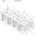
- Thisis fabricated, as illustrated in FIG. 11 , by press-molding a metal flat plate to form a pair of manifolds (not illustrated), and drilling a plurality of slits 2 between these. Between each of the slits 2 , a fin part is formed by long and thin longitudinal ribs 3 that are in parallel to each other and transverse ribs 4 that link between the adjacent longitudinal ribs 3 to constitute a flat plate. Further, lamination is performed so that, in the fin part of each plate, the longitudinal ribs 3 thereof are matched with each other and the transverse ribs 4 are offset in the length direction of the plate from each other.
- an end lid 7On both ends in the lamination direction of the laminated body of plates, an end lid 7 is arranged, a semiconductor element such as an inverter is mounted on the end lid 7 , and a refrigerant is circulated into the fin part of each plate via the manifold.
- a semiconductor elementsuch as an inverter
- ranges in which heat exchange is performed activelyare respective ranges formed in a reverse trapezoidal shape downward and shown by dotted cross-section areas and cross-hatched cross-section areas of the refrigerant.
- cross-section areas of the refrigerant neither dotted nor cross-hatchedare illustrated by trapezoids rising from a lower side toward an upper side in which in which heat exchange is less likely to be performed.
- the present inventionaims at feeding a refrigerant predominantly to portions in which heat exchange is actively performed to totally accelerate heat exchange.
- a first aspect of the present inventionis a laminated type heat sink, in which:
- the laminated type heat sinkcomprises a plurality of flat plates ( 6 ) each including a metal flat plate provided with a pair of manifold parts ( 1 ) facing each other, and, between the manifold parts ( 1 ), a fin part ( 5 ) with a plurality of slits ( 2 ) punched out in parallel to each other, and a plurality of thin and long longitudinal ribs ( 3 ) in parallel to each other and transverse ribs ( 4 ) linking adjacent respective longitudinal ribs ( 3 ) formed between the slits ( 2 );
- respective plates ( 6 )are laminated so that, with respect to each of fin parts ( 5 ) of respective plates ( 6 ), the longitudinal ribs ( 3 ) are matched with each other and positions of the transverse ribs ( 4 ) are offset in a longitudinal rib ( 3 ) direction from each other, and an end lid ( 7 ) is arranged to both ends thereof in a lamination direction; and
- a refrigerantis circulated to each of the slits ( 2 ) in a longitudinal rib ( 3 ) direction and an object ( 8 ) to be cooled is joined to the end lid ( 7 ),
- a circulation blocking means ( 9 ) for a refrigerantis provided so that refrigerant circulation resistance in the fin part ( 5 ) of the plate ( 6 ) at a position sufficiently apart in a lamination direction from the object ( 8 ) to be cooled is greater than circulation resistance in each plate ( 6 ) lying close to the object ( 8 ) to be cooled.
- a second aspect of the present inventionis the laminated type heat sink according to the first aspect, wherein:
- the plurality of slits ( 2 )is formed in a projection position of the object ( 8 ) to be cooled and other parts are formed into a blank part ( 11 ) without a slit.
- a third aspect of the present inventionis the laminated type heat sink according to the first aspect, wherein:
- a third plate ( 6 b ) having a fin part different from the fin part ( 5 )is arranged in a position sufficiently apart in a laminate direction from the object ( 8 ) to be cooled while a periphery and manifold part ( 1 ) are matched with the respective plates ( 6 );
- a blockade wall ( 14 ) rising orthogonally to a planeis arranged in a part on a side orthogonal to circulation direction of a refrigerant;
- a fourth aspect of the present inventionis the laminated type heat sink of the first aspect, wherein:
- the circulation blocking means ( 9 )includes a barrier body ( 15 ) that is arranged in a position sufficiently apart in a lamination direction from the object ( 8 ) to be cooled, has a width being matched with the manifold part ( 1 ), and is a member separate from a plate ( 6 ) which has at least an L letter-like part ( 15 a ) in the horizontal section; and
- a fifth aspect of the present inventionis a laminated type heat sink, in which:
- the laminated type heat sinkcomprises a plurality of flat plates ( 21 ) each including a metal flat plate provided with a fin part ( 5 ) with a plurality of slits ( 2 ) punched out in parallel to each other, and a plurality of thin and long longitudinal ribs ( 3 ) in parallel to each other and transverse ribs ( 4 ) linking adjacent respective longitudinal ribs ( 3 ) formed between the slits ( 2 );
- respective plates ( 21 )are laminated so that, with respect to each of fin parts ( 5 ) of respective plates ( 21 ), the longitudinal ribs ( 3 ) are matched with each other and positions of the transverse ribs ( 4 ) are offset in a longitudinal rib ( 3 ) direction from each other to form a core ( 18 );
- a casing ( 19 ) formed in a dish-like shape on at least one sideis included and the core ( 18 ) is housed in the casing ( 19 );
- a refrigerantis circulated into each of the slits ( 2 ) in a longitudinal rib ( 3 ) direction and an object ( 8 ) to be cooled is joined to the casing ( 19 ),
- a circulation blocking means ( 9 ) for a refrigerantis provided so that refrigerant circulation resistance in a fin part ( 5 ) of a plate ( 21 ) at a position sufficiently apart in a lamination direction from the object ( 8 ) to be cooled is greater than circulation resistance in each plate ( 21 ) lying close to the object ( 8 ) to be cooled.
- a sixth aspect of the present inventionis the laminated type heat sink of the fifth aspect, wherein:
- a second plate ( 21 a ) having a fin part different from the fin part ( 5 ) of othersis included in a position apart from the object ( 8 ) to be cooled;
- the plurality of slits ( 2 )is formed in a projection position of the object ( 8 ) to be cooled and other parts are formed into a blank part ( 11 ) without a slit.
- a seventh aspect of the present inventionis the laminated type heat sink the fifth aspect, wherein:
- a third plate ( 21 b ) having a fin part different from the fin part ( 5 )is arranged in a position sufficiently apart in a lamination direction from the object ( 8 ) to be cooled;
- a blockade wall ( 14 ) rising orthogonally to a planeis arranged in a part on a side perpendicular to a flow direction of a refrigerant;
- An eighth aspect of the present inventionis the laminated type heat sink of the fifth aspect, wherein:
- the core ( 18 )is arranged in the casing ( 19 ) via a manifold part ( 20 ), and, between the core ( 18 ) and an inner wall of the casing ( 19 ), a barrier body ( 15 ) that is a member separate from the plate ( 21 ) is interposed; and
- the barrier body ( 15 )has at least an L letter-like part ( 15 a ) in a horizontal section, and a position of a side wall that is a side part of the each plate ( 21 ) apart, when the object ( 8 ) to be cooled is projected to each plate ( 21 ), only that portion of the plate is not blockaded with the L letter-like part ( 15 a ) of the barrier body ( 15 ).
- the laminated type heat sink of the present inventionis provided with a circulation blocking means 9 for a refrigerant so that, in positions sufficiently apart in a lamination direction from an object 8 to be cooled, a circulation path of a refrigerant in a fin part of respective plates 6 decreases in a lower portion of the respective plates 6 .
- the refrigerantcan be circulated in a larger quantity into plates nearer to the object 8 to be cooled to accelerate heat exchange.
- the laminated type heat sink of the second aspecthas, in the above configuration, a second plate 6 a with the plurality of slits 2 formed in a projection position of the object 8 to be cooled and other parts formed into a blank part 11 without a slit.
- the laminated type heat sink of the third aspectis characterized in that, in connection with the first aspect, a third plate 6 b thereof includes a blockade wall 14 rising orthogonally to a plane in a part on a side orthogonal to a refrigerant flow direction, and a position of the side part that is a side part of the each plate 6 apart, when the object 8 to be cooled is projected to each plate 6 , only that portion of the plate is not blockaded with the blockade wall 14 .
- one third plate 6 bblockades a side portion of other plate 6 and, without circulating a fluid into a portion of the plate 6 that does not actively contribute to cooling, the refrigerant can be circulated into other portions to accelerate heat exchange.
- the laminated type heat sink of the fourth aspectis characterized, in connection with the first aspect, by having a barrier body 15 that is a separate member from the plate 6 , and blockading a side part of the respective plates 6 with an L letter-like part 15 a of the barrier body 15 .
- a core 18 including a laminated body of a plate 21is internally mounted in a casing 19 . Consequently, a laminated type heat sink that has a simple structure and is easily manufactured and assembled can be provided.
- FIG. 1illustrates an exploded perspective view of a laminated type heat sink of the present invention.
- FIG. 2illustrates a perspective view showing an assembled state of the same.
- FIG. 3illustrates a cross-sectional view along a arrow in FIG. 2 .
- FIG. 4illustrates perspective views showing a third plate 6 b for use in second Example of the present invention and a core of a heat sink using the same.
- FIG. 5illustrates perspective views showing a barrier body 15 in third Example of the present invention and a core of a heat sink using the same.
- FIG. 6illustrates an explanatory view showing heat exchange regions in a longitudinal section of a heat sink.
- FIG. 7illustrates an explanatory view showing a difference of heat resistance between a heat sink according to the preset invention and a heat sink of a conventional type.
- FIG. 8illustrates an exploded perspective view of a laminated type heat sink in fourth Example of the present invention.
- FIG. 9illustrates an exploded perspective view of a laminated type heat sink in fifth Example of the present invention.
- FIG. 10illustrates an exploded perspective view of a laminated type heat sink in sixth Example of the present invention.
- FIG. 11illustrates a principal part perspective view of a laminated type heat sink of a conventional type.
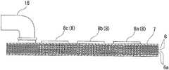
- FIG. 1illustrates an exploded perspective view of a heat sink of the present invention
- FIG. 2illustrates an assembled state of the same
- FIG. 3illustrates a longitudinal cross-sectional view of the assembled state.
- a coreis formed by a laminated body of a plurality of plates 6 and second plates 6 a , and an end lid 7 is arranged to both upper and lower ends of the core. Then, each of plates is integrally brazed to each other.
- the plate 6 lying on the end lid 7 sideis the plate of a conventional type illustrated in FIG. 11 , in which a pair of manifold parts 1 in parallel to each other are formed on both sides in a width direction of a metal flat plate, and, between the respective manifold parts 1 , a fin part 5 is arranged.
- the fin part 5is formed as the conventional one illustrated in FIG. 11 , a plurality of slits 2 is arranged in parallel, longitudinal ribs 3 are arranged between the respective slits 2 , and transverse ribs 4 link between the respective longitudinal ribs 3 . Then, each of the slits 2 is matched with each other and laminated, and each of the transverse ribs 4 is arranged in a different position for each of adjacent plates.
- the second plate 6 a arranged in a position apart from the end lid 7lies on a lower side in a lamination direction, as illustrated in FIG. 1 . That is, it is the second plate 6 a arranged farther relative to the end lid 7 having an object 8 to be cooled, and the fin part 5 and a blank part 11 are arranged alternately between the manifold parts 1 .
- three objects 8 to be cooledthat is, 8 a to 8 c are joined on the end lid 7 , but the number of objects to be cooled is not limited to this.
- a pair of inlet/outlet pipes 16are arranged to the end lid 7 on the upper side, each of which is communicated with the pair of manifold parts 1 of each of the plates 6 and second plates 6 a .
- the objects 8 a to 8 c to be cooledare arranged to the end lid 7 on the upper side.
- a refrigerant 17is fed to each manifold part 1 of each of the plates 6 and second plates 6 a , which winds in up/down directions through the slit 2 in the fin part 5 thereof and circulates from one manifold part 1 to the other manifold part 1 .
- the refrigerant 17circulates evenly through the slit of each of the fin parts 5 in the plate 6 lying near the end lid 7 on the upper side.
- the refrigerant 17does not circulate into the blank part 11 (which constitutes a circulation blocking means 9 of the present invention), and circulates only into a part of the fin part 5 of the second plate 6 a .
- the refrigerant 17is fed intensively to the fin part 5 . Consequently, in regions in which heat exchange is less in FIG. 6 (portions rising in a trapezoid-like shape from a lower side), the refrigerant is fed only to the fin part 5 and not fed to the blank part 11 . Consequently, the refrigerant is fed to the fin part 5 more effectively to accelerate heat exchange as a whole.
- the objects 8 a to 8 c to be cooledare arranged only to the end lid 7 on the upper side, but an object to be cooled can also be arranged to the end lid 7 on the lower side together with the end lid 7 on the upper side.
- the plurality of second plates 6 ais arranged at a middle height, and, on both sides thereof, a laminated body of the ordinary plate 6 is arranged.
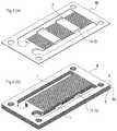
- FIG. 4illustrates a core part of a heat sink in second Example of the present invention, and a third plate 6 b used for the core part.
- the core partincludes a laminated body in which only a plate lying at the lowest end in a lamination direction is the third plate 6 b and all the other plates are the conventional plate 6 .
- the blockade walls 14 of the third plate 6 b lying at the lowest endblockade, respectively, both sides of the plate 6 lying on a lower side as in FIG. 4(B) .
- an object to be cooledis arranged to a not illustrated end lid lying at the highest end.
- the blockade walls 14 in vertically reversed directionsare mounted, respectively, on not illustrated two third plates 6 b lying in the middle.
- FIG. 5illustrates third Example of the present invention.
- a coreis formed by a laminated body of the ordinary plate 6 , and, to each manifold part 1 thereof, a barrier body 15 illustrated in FIG. 5(A) is arranged.
- the barrier body 15has a width equal to the width of the manifold part 1 , and a length equal to the base arranged in a trapezoid-like shape from a lower side toward an upper side in FIG. 6 . Then the barrier body 15 is arranged to a position of the upward trapezoid-like shape in FIG. 6 .
- the barrier body 15forms the circulation blocking means 9 of the present invention. Meanwhile, in FIG.
- the exampleis also an example in which an object to be cooled is arranged to a not illustrated upper end lid, and the same can also be arranged to a lower end lid.
- the barrier bodies 15 in vertically reversed directionsare arranged on a plate part lying in the middle. Then, a part of the fin part 5 of each of the plates 6 is partially blockaded by each L letter-like part 15 a.
- FIG. 7illustrates a comparison between heat resistance of a conventional type heat sink and heat resistance of the heat sink of the present invention (arrangement of the object 8 to be cooled in FIG. 2 ).
- the heat resistance in the present inventionis smaller than that in the conventional type.
- the heat resistancehere is a value that shows difficulty of temperature transmission, and means temperature rise per unit time and per quantity of heat generation with a unit of ° C./W.
- white in the bar graphshows the heat resistance of the conventional laminated type heat sink in which respective plates are identical.
- the heat resistance of the heat sink of the present inventionis shown by slash marks in each bar graph.
- the heat resistance of the conventional articleis 0.194° C./W.
- the heat resistance in the present inventionis 0.193° C./W.
- FIG. 8illustrates an exploded perspective view of fourth Example of the present invention.
- the different point of this from the invention in FIG. 1is that a frame part of the periphery of each of the plates 6 in FIG. 1 is removed.
- the core 18is formed by a laminated body of plates 21 , and the core 18 is mounted inside a casing 19 .
- a pair of dish-like platesare sealed with a flange part of periphery and the pair of inlet/outlet pipes 16 are projected from an end part.
- the blank part 11exists in two positions in a second plate 21 a without a frame, and the blank part 11 forms the circulation blocking means 9 .
- FIG. 9illustrates an exploded perspective view of fifth Example of the present invention.
- the different point of this from the invention in FIG. 4is that a frame part of the periphery of each of the plates 6 in FIG. 4 is removed.
- FIG. 10illustrates an exploded perspective view of sixth Example of the present invention.
- the different point of this from the invention in FIG. 5is that a frame part of the periphery of each of the plates 6 in FIG. 5 is removed.
- the present inventioncan be used for cooling a semiconductor such as an inverter.
Landscapes
- Engineering & Computer Science (AREA)
- Physics & Mathematics (AREA)
- Thermal Sciences (AREA)
- General Engineering & Computer Science (AREA)
- Mechanical Engineering (AREA)
- Microelectronics & Electronic Packaging (AREA)
- Computer Hardware Design (AREA)
- Power Engineering (AREA)
- General Physics & Mathematics (AREA)
- Condensed Matter Physics & Semiconductors (AREA)
- Chemical & Material Sciences (AREA)
- Dispersion Chemistry (AREA)
- Cooling Or The Like Of Semiconductors Or Solid State Devices (AREA)
- Cooling Or The Like Of Electrical Apparatus (AREA)
Abstract
Description
Claims (8)
Applications Claiming Priority (3)
| Application Number | Priority Date | Filing Date | Title |
|---|---|---|---|
| JP2015184706 | 2015-09-18 | ||
| JP2015-184706 | 2015-09-18 | ||
| PCT/JP2016/078132WO2017047825A1 (en) | 2015-09-18 | 2016-09-14 | Laminated type heat sink |
Publications (2)
| Publication Number | Publication Date |
|---|---|
| US20180245862A1 US20180245862A1 (en) | 2018-08-30 |
| US10655922B2true US10655922B2 (en) | 2020-05-19 |
Family
ID=58289403
Family Applications (1)
| Application Number | Title | Priority Date | Filing Date |
|---|---|---|---|
| US15/754,505Active2036-10-07US10655922B2 (en) | 2015-09-18 | 2016-09-14 | Laminated heat sink |
Country Status (5)
| Country | Link |
|---|---|
| US (1) | US10655922B2 (en) |
| EP (1) | EP3352216B1 (en) |
| JP (1) | JP6746594B2 (en) |
| CN (1) | CN107924898B (en) |
| WO (1) | WO2017047825A1 (en) |
Cited By (4)
| Publication number | Priority date | Publication date | Assignee | Title |
|---|---|---|---|---|
| US20200258815A1 (en)* | 2017-08-29 | 2020-08-13 | Welcon Inc. | Heat sink |
| US10837718B2 (en)* | 2015-09-18 | 2020-11-17 | T.Rad Co., Ltd. | Laminated core type heat sink |
| WO2022018027A1 (en)* | 2020-07-21 | 2022-01-27 | Mahle International Gmbh | Heat exchanger for cooling an inductive charging device, and inductive charging device |
| US20220155020A1 (en)* | 2019-04-12 | 2022-05-19 | T.Rad Co., Ltd. | Stacked plate heat exchanger |
Families Citing this family (14)
| Publication number | Priority date | Publication date | Assignee | Title |
|---|---|---|---|---|
| US10766097B2 (en)* | 2017-04-13 | 2020-09-08 | Raytheon Company | Integration of ultrasonic additive manufactured thermal structures in brazements |
| US10462941B2 (en) | 2017-11-06 | 2019-10-29 | Caterpillar Inc. | Heat sink assembly |
| JP6663899B2 (en)* | 2017-11-29 | 2020-03-13 | 本田技研工業株式会社 | Cooling system |
| JP7015197B2 (en)* | 2018-03-26 | 2022-02-02 | 新光電気工業株式会社 | Loop type heat pipe and its manufacturing method |
| CN110543069A (en)* | 2018-05-28 | 2019-12-06 | 中强光电股份有限公司 | Liquid-cooled radiator |
| FR3100671A1 (en)* | 2019-09-06 | 2021-03-12 | Valeo Siemens Eautomotive France Sas | Plastic cover for closing a fluid cooling circuit, for electrical equipment |
| CN111473670A (en)* | 2020-04-09 | 2020-07-31 | 浙江嘉熙科技有限公司 | Heat superconducting heat transfer plate and heat sink |
| JP7730240B2 (en)* | 2020-12-26 | 2025-08-27 | インターナショナル・ビジネス・マシーンズ・コーポレーション | Cold plate device, method of manufacturing a cold plate device, and method of improving flow uniformity through the effective volume of a cold plate device - Patents.com |
| US11698233B2 (en)* | 2020-12-26 | 2023-07-11 | International Business Machines Corporation | Reduced pressure drop cold plate transition |
| US12004322B2 (en) | 2020-12-26 | 2024-06-04 | International Business Machines Corporation | Cold plate with uniform plenum flow |
| US11832423B2 (en)* | 2021-03-23 | 2023-11-28 | Baidu Usa Llc | Liquid cooling unit for peripheral devices |
| DE112022002374T5 (en)* | 2021-04-25 | 2024-04-04 | Danfoss Silicon Power Gmbh | Coolers for electronic components |
| US12096594B2 (en)* | 2021-09-23 | 2024-09-17 | The Esab Group Inc. | Fluidic routing structures for liquid cooling of power modules of power supplies |
| FR3154799A1 (en)* | 2023-10-26 | 2025-05-02 | Valeo Systemes Thermiques | Thermal regulation device |
Citations (28)
| Publication number | Priority date | Publication date | Assignee | Title |
|---|---|---|---|---|
| US4397234A (en)* | 1981-12-30 | 1983-08-09 | International Business Machines Corporation | Electromagnetic print hammer coil assembly |
| US5274920A (en)* | 1991-04-02 | 1994-01-04 | Microunity Systems Engineering | Method of fabricating a heat exchanger for solid-state electronic devices |
| US20030152488A1 (en)* | 2002-02-14 | 2003-08-14 | Tonkovich Anna Lee | Methods of making devices by stacking sheets and processes of conducting unit operations using such devices |
| US20030179596A1 (en)* | 2000-11-07 | 2003-09-25 | Craig Joseph | Electrical bus with associated porous metal heat sink and method of manufacturing same |
| US20050133212A1 (en)* | 2003-12-18 | 2005-06-23 | Wilson Michael J. | Forced fluid heat sink |
| US20050189342A1 (en)* | 2004-02-23 | 2005-09-01 | Samer Kabbani | Miniature fluid-cooled heat sink with integral heater |
| US6989134B2 (en)* | 2002-11-27 | 2006-01-24 | Velocys Inc. | Microchannel apparatus, methods of making microchannel apparatus, and processes of conducting unit operations |
| US6994245B2 (en)* | 2003-10-17 | 2006-02-07 | James M. Pinchot | Micro-reactor fabrication |
| US20070163765A1 (en)* | 2003-10-31 | 2007-07-19 | Patrick Rondier | Power-electronic-cooling device |
| US7247030B2 (en)* | 2004-04-05 | 2007-07-24 | Tyco Electronics Corporation | Bonded three dimensional laminate structure |
| US20070246204A1 (en)* | 2006-04-21 | 2007-10-25 | Foxconn Technology Co., Ltd. | Liquid-cooling device |
| JP2008171840A (en) | 2007-01-05 | 2008-07-24 | T Rad Co Ltd | Liquid-cooled heat sink and design method thereof |
| US20090165996A1 (en)* | 2007-12-26 | 2009-07-02 | Lynch Thomas W | Reticulated heat dissipation with coolant |
| US20090326279A1 (en)* | 2005-05-25 | 2009-12-31 | Anna Lee Tonkovich | Support for use in microchannel processing |
| US20100032147A1 (en)* | 2008-08-08 | 2010-02-11 | Mikros Manufacturing, Inc. | Heat exchanger having winding micro-channels |
| US20110226448A1 (en)* | 2008-08-08 | 2011-09-22 | Mikros Manufacturing, Inc. | Heat exchanger having winding channels |
| US8122909B2 (en)* | 2005-03-23 | 2012-02-28 | Velocys | Surface features in microprocess technology |
| JP2013030713A (en) | 2011-07-29 | 2013-02-07 | T Rad Co Ltd | Liquid cooled heat sink |
| US8585990B2 (en)* | 2010-05-04 | 2013-11-19 | Korea Institute Of Science And Technology | Micro-macro channel reactor |
| JP2013235976A (en) | 2012-05-09 | 2013-11-21 | Tdk Corp | Laminate capacitor |
| JP2014033063A (en) | 2012-08-03 | 2014-02-20 | T Rad Co Ltd | Core of layered heat sink |
| US20140231055A1 (en)* | 2011-09-06 | 2014-08-21 | Vacuum Process Engineering, Inc. | Heat Exchanger Produced from Laminar Elements |
| WO2015079643A1 (en) | 2013-11-28 | 2015-06-04 | 富士電機株式会社 | Method of manufacturing cooler for semiconductor module, cooler for semiconductor module, semiconductor module, and electrically driven vehicle |
| US9333477B2 (en)* | 2011-04-15 | 2016-05-10 | Korea Institute Of Energy Research | Hydrocarbon reforming device using micro channel heater |
| US9599407B2 (en)* | 2009-07-29 | 2017-03-21 | Tokitae Llc | System and structure for heating or sterilizing a liquid stream |
| US10203165B2 (en)* | 2014-07-23 | 2019-02-12 | Muller & Cie | Device and method for storing thermal energy |
| US20190335617A1 (en)* | 2014-12-05 | 2019-10-31 | International Business Machines Corporation | Cooling structure for electronic boards |
| US20190393133A1 (en)* | 2017-03-16 | 2019-12-26 | Mitsubishi Electric Corporation | Cooling system |
Family Cites Families (1)
| Publication number | Priority date | Publication date | Assignee | Title |
|---|---|---|---|---|
| JP4881583B2 (en)* | 2005-06-27 | 2012-02-22 | 株式会社豊田自動織機 | Power module heat sink |
- 2016
- 2016-09-14EPEP16846696.9Apatent/EP3352216B1/enactiveActive
- 2016-09-14USUS15/754,505patent/US10655922B2/enactiveActive
- 2016-09-14JPJP2017540530Apatent/JP6746594B2/enactiveActive
- 2016-09-14CNCN201680048097.0Apatent/CN107924898B/enactiveActive
- 2016-09-14WOPCT/JP2016/078132patent/WO2017047825A1/ennot_activeCeased
Patent Citations (29)
| Publication number | Priority date | Publication date | Assignee | Title |
|---|---|---|---|---|
| US4397234A (en)* | 1981-12-30 | 1983-08-09 | International Business Machines Corporation | Electromagnetic print hammer coil assembly |
| US5274920A (en)* | 1991-04-02 | 1994-01-04 | Microunity Systems Engineering | Method of fabricating a heat exchanger for solid-state electronic devices |
| US20030179596A1 (en)* | 2000-11-07 | 2003-09-25 | Craig Joseph | Electrical bus with associated porous metal heat sink and method of manufacturing same |
| US20030152488A1 (en)* | 2002-02-14 | 2003-08-14 | Tonkovich Anna Lee | Methods of making devices by stacking sheets and processes of conducting unit operations using such devices |
| US6989134B2 (en)* | 2002-11-27 | 2006-01-24 | Velocys Inc. | Microchannel apparatus, methods of making microchannel apparatus, and processes of conducting unit operations |
| US6994245B2 (en)* | 2003-10-17 | 2006-02-07 | James M. Pinchot | Micro-reactor fabrication |
| US20070163765A1 (en)* | 2003-10-31 | 2007-07-19 | Patrick Rondier | Power-electronic-cooling device |
| US20050133212A1 (en)* | 2003-12-18 | 2005-06-23 | Wilson Michael J. | Forced fluid heat sink |
| US20050189342A1 (en)* | 2004-02-23 | 2005-09-01 | Samer Kabbani | Miniature fluid-cooled heat sink with integral heater |
| US7247030B2 (en)* | 2004-04-05 | 2007-07-24 | Tyco Electronics Corporation | Bonded three dimensional laminate structure |
| US8122909B2 (en)* | 2005-03-23 | 2012-02-28 | Velocys | Surface features in microprocess technology |
| US20090326279A1 (en)* | 2005-05-25 | 2009-12-31 | Anna Lee Tonkovich | Support for use in microchannel processing |
| US20070246204A1 (en)* | 2006-04-21 | 2007-10-25 | Foxconn Technology Co., Ltd. | Liquid-cooling device |
| JP2008171840A (en) | 2007-01-05 | 2008-07-24 | T Rad Co Ltd | Liquid-cooled heat sink and design method thereof |
| US20090165996A1 (en)* | 2007-12-26 | 2009-07-02 | Lynch Thomas W | Reticulated heat dissipation with coolant |
| US20100032147A1 (en)* | 2008-08-08 | 2010-02-11 | Mikros Manufacturing, Inc. | Heat exchanger having winding micro-channels |
| US20110226448A1 (en)* | 2008-08-08 | 2011-09-22 | Mikros Manufacturing, Inc. | Heat exchanger having winding channels |
| US9599407B2 (en)* | 2009-07-29 | 2017-03-21 | Tokitae Llc | System and structure for heating or sterilizing a liquid stream |
| US8585990B2 (en)* | 2010-05-04 | 2013-11-19 | Korea Institute Of Science And Technology | Micro-macro channel reactor |
| US9333477B2 (en)* | 2011-04-15 | 2016-05-10 | Korea Institute Of Energy Research | Hydrocarbon reforming device using micro channel heater |
| JP2013030713A (en) | 2011-07-29 | 2013-02-07 | T Rad Co Ltd | Liquid cooled heat sink |
| US20140231055A1 (en)* | 2011-09-06 | 2014-08-21 | Vacuum Process Engineering, Inc. | Heat Exchanger Produced from Laminar Elements |
| JP2013235976A (en) | 2012-05-09 | 2013-11-21 | Tdk Corp | Laminate capacitor |
| JP2014033063A (en) | 2012-08-03 | 2014-02-20 | T Rad Co Ltd | Core of layered heat sink |
| WO2015079643A1 (en) | 2013-11-28 | 2015-06-04 | 富士電機株式会社 | Method of manufacturing cooler for semiconductor module, cooler for semiconductor module, semiconductor module, and electrically driven vehicle |
| US20160129792A1 (en) | 2013-11-28 | 2016-05-12 | Fuji Electric Co., Ltd. | Method for manufacturing cooler for semiconductor-module, cooler for semiconductor-module, semiconductor-module and electrically-driven vehicle |
| US10203165B2 (en)* | 2014-07-23 | 2019-02-12 | Muller & Cie | Device and method for storing thermal energy |
| US20190335617A1 (en)* | 2014-12-05 | 2019-10-31 | International Business Machines Corporation | Cooling structure for electronic boards |
| US20190393133A1 (en)* | 2017-03-16 | 2019-12-26 | Mitsubishi Electric Corporation | Cooling system |
Cited By (9)
| Publication number | Priority date | Publication date | Assignee | Title |
|---|---|---|---|---|
| US10837718B2 (en)* | 2015-09-18 | 2020-11-17 | T.Rad Co., Ltd. | Laminated core type heat sink |
| US20200258815A1 (en)* | 2017-08-29 | 2020-08-13 | Welcon Inc. | Heat sink |
| US11948860B2 (en)* | 2017-08-29 | 2024-04-02 | Welcon Inc. | Heat sink |
| US12211768B2 (en) | 2017-08-29 | 2025-01-28 | Welcon Inc. | Heat sink |
| US20220155020A1 (en)* | 2019-04-12 | 2022-05-19 | T.Rad Co., Ltd. | Stacked plate heat exchanger |
| US11740027B2 (en)* | 2019-04-12 | 2023-08-29 | T.Rad Co., Ltd. | Stacked plate heat exchanger |
| WO2022018027A1 (en)* | 2020-07-21 | 2022-01-27 | Mahle International Gmbh | Heat exchanger for cooling an inductive charging device, and inductive charging device |
| US20240367533A1 (en)* | 2020-07-21 | 2024-11-07 | Mahle International Gmbh | Heat exchanger for cooling an inductive charging device and inductive charging device |
| US12208699B2 (en)* | 2020-07-21 | 2025-01-28 | Mahle International Gmbh | Heat exchanger for cooling an inductive charging device and inductive charging device |
Also Published As
| Publication number | Publication date |
|---|---|
| CN107924898A (en) | 2018-04-17 |
| US20180245862A1 (en) | 2018-08-30 |
| JPWO2017047825A1 (en) | 2018-07-05 |
| WO2017047825A1 (en) | 2017-03-23 |
| CN107924898B (en) | 2020-10-27 |
| JP6746594B2 (en) | 2020-08-26 |
| EP3352216A1 (en) | 2018-07-25 |
| EP3352216A4 (en) | 2019-05-08 |
| EP3352216B1 (en) | 2021-11-10 |
Similar Documents
| Publication | Publication Date | Title |
|---|---|---|
| US10655922B2 (en) | Laminated heat sink | |
| JP5983565B2 (en) | Cooler | |
| CN102735091B (en) | Heat exchanger | |
| US9803933B2 (en) | Cold storage medium container | |
| JP6358872B2 (en) | Boiling cooler for heating element | |
| US10224263B2 (en) | Heat exchanger | |
| US11740027B2 (en) | Stacked plate heat exchanger | |
| CN109073342B (en) | Heat exchanger | |
| JP5264792B2 (en) | Plate heat exchanger | |
| JP5901416B2 (en) | Fin for heat exchanger, heat sink using the same, and method for manufacturing fin for heat exchanger | |
| JP2013130300A (en) | Stacked heat exchanger | |
| WO2011114616A1 (en) | Ebullient cooling device | |
| KR20170121756A (en) | Cooling water waste heat recovering heat exchanger manufacturing method thereof | |
| KR102387580B1 (en) | heat exchanger for cooling electric element | |
| JP5821710B2 (en) | Power module device | |
| JP6627720B2 (en) | Stacked heat exchanger | |
| JP6291262B2 (en) | Heat exchanger | |
| JP7514653B2 (en) | Heat exchanger | |
| MY204348A (en) | Plate-fin stacked heat exchanger and refrigeration system using same | |
| KR20180033488A (en) | manufacturing method of cooling water waste heat recovering heat exchanger | |
| JP6392659B2 (en) | Heat exchanger and manufacturing method thereof | |
| KR102808792B1 (en) | Heat exchanger | |
| JP2019021872A (en) | Laminate heat exchanger | |
| JP6691652B2 (en) | Heat transfer device for cooling | |
| JP2018009719A5 (en) |
Legal Events
| Date | Code | Title | Description |
|---|---|---|---|
| AS | Assignment | Owner name:T.RAD CO., LTD., JAPAN Free format text:ASSIGNMENT OF ASSIGNORS INTEREST;ASSIGNORS:BUNGO, TAKUYA;OKUBO, ATSUSHI;SAKAI, TAIJI;REEL/FRAME:045008/0652 Effective date:20180212 | |
| FEPP | Fee payment procedure | Free format text:ENTITY STATUS SET TO UNDISCOUNTED (ORIGINAL EVENT CODE: BIG.); ENTITY STATUS OF PATENT OWNER: LARGE ENTITY | |
| STPP | Information on status: patent application and granting procedure in general | Free format text:DOCKETED NEW CASE - READY FOR EXAMINATION | |
| STPP | Information on status: patent application and granting procedure in general | Free format text:NON FINAL ACTION MAILED | |
| STPP | Information on status: patent application and granting procedure in general | Free format text:RESPONSE TO NON-FINAL OFFICE ACTION ENTERED AND FORWARDED TO EXAMINER | |
| STPP | Information on status: patent application and granting procedure in general | Free format text:EX PARTE QUAYLE ACTION MAILED | |
| STPP | Information on status: patent application and granting procedure in general | Free format text:RESPONSE TO EX PARTE QUAYLE ACTION ENTERED AND FORWARDED TO EXAMINER | |
| STPP | Information on status: patent application and granting procedure in general | Free format text:PUBLICATIONS -- ISSUE FEE PAYMENT RECEIVED | |
| STPP | Information on status: patent application and granting procedure in general | Free format text:PUBLICATIONS -- ISSUE FEE PAYMENT VERIFIED | |
| STCF | Information on status: patent grant | Free format text:PATENTED CASE | |
| MAFP | Maintenance fee payment | Free format text:PAYMENT OF MAINTENANCE FEE, 4TH YEAR, LARGE ENTITY (ORIGINAL EVENT CODE: M1551); ENTITY STATUS OF PATENT OWNER: LARGE ENTITY Year of fee payment:4 |