US10655881B2 - Thermostat with halo light system and emergency directions - Google Patents
Thermostat with halo light system and emergency directionsDownload PDFInfo
- Publication number
- US10655881B2 US10655881B2US16/246,366US201916246366AUS10655881B2US 10655881 B2US10655881 B2US 10655881B2US 201916246366 AUS201916246366 AUS 201916246366AUS 10655881 B2US10655881 B2US 10655881B2
- Authority
- US
- United States
- Prior art keywords
- user
- building
- emergency
- control device
- display device
- Prior art date
- Legal status (The legal status is an assumption and is not a legal conclusion. Google has not performed a legal analysis and makes no representation as to the accuracy of the status listed.)
- Active
Links
Images


Classifications
- F—MECHANICAL ENGINEERING; LIGHTING; HEATING; WEAPONS; BLASTING
- F24—HEATING; RANGES; VENTILATING
- F24F—AIR-CONDITIONING; AIR-HUMIDIFICATION; VENTILATION; USE OF AIR CURRENTS FOR SCREENING
- F24F11/00—Control or safety arrangements
- F24F11/50—Control or safety arrangements characterised by user interfaces or communication
- F24F11/52—Indication arrangements, e.g. displays
- F—MECHANICAL ENGINEERING; LIGHTING; HEATING; WEAPONS; BLASTING
- F21—LIGHTING
- F21V—FUNCTIONAL FEATURES OR DETAILS OF LIGHTING DEVICES OR SYSTEMS THEREOF; STRUCTURAL COMBINATIONS OF LIGHTING DEVICES WITH OTHER ARTICLES, NOT OTHERWISE PROVIDED FOR
- F21V33/00—Structural combinations of lighting devices with other articles, not otherwise provided for
- F21V33/0088—Ventilating systems
- F21V33/0092—Ventilating systems with heating or cooling devices
- F—MECHANICAL ENGINEERING; LIGHTING; HEATING; WEAPONS; BLASTING
- F24—HEATING; RANGES; VENTILATING
- F24F—AIR-CONDITIONING; AIR-HUMIDIFICATION; VENTILATION; USE OF AIR CURRENTS FOR SCREENING
- F24F11/00—Control or safety arrangements
- F24F11/62—Control or safety arrangements characterised by the type of control or by internal processing, e.g. using fuzzy logic, adaptive control or estimation of values
- F24F11/63—Electronic processing
- F—MECHANICAL ENGINEERING; LIGHTING; HEATING; WEAPONS; BLASTING
- F24—HEATING; RANGES; VENTILATING
- F24F—AIR-CONDITIONING; AIR-HUMIDIFICATION; VENTILATION; USE OF AIR CURRENTS FOR SCREENING
- F24F11/00—Control or safety arrangements
- F24F11/88—Electrical aspects, e.g. circuits
- G—PHYSICS
- G05—CONTROLLING; REGULATING
- G05D—SYSTEMS FOR CONTROLLING OR REGULATING NON-ELECTRIC VARIABLES
- G05D23/00—Control of temperature
- G05D23/19—Control of temperature characterised by the use of electric means
- G05D23/1917—Control of temperature characterised by the use of electric means using digital means
- G—PHYSICS
- G08—SIGNALLING
- G08B—SIGNALLING OR CALLING SYSTEMS; ORDER TELEGRAPHS; ALARM SYSTEMS
- G08B19/00—Alarms responsive to two or more different undesired or abnormal conditions, e.g. burglary and fire, abnormal temperature and abnormal rate of flow
- G—PHYSICS
- G08—SIGNALLING
- G08B—SIGNALLING OR CALLING SYSTEMS; ORDER TELEGRAPHS; ALARM SYSTEMS
- G08B21/00—Alarms responsive to a single specified undesired or abnormal condition and not otherwise provided for
- G08B21/02—Alarms for ensuring the safety of persons
- G08B21/10—Alarms for ensuring the safety of persons responsive to calamitous events, e.g. tornados or earthquakes
- G—PHYSICS
- G08—SIGNALLING
- G08B—SIGNALLING OR CALLING SYSTEMS; ORDER TELEGRAPHS; ALARM SYSTEMS
- G08B25/00—Alarm systems in which the location of the alarm condition is signalled to a central station, e.g. fire or police telegraphic systems
- G08B25/01—Alarm systems in which the location of the alarm condition is signalled to a central station, e.g. fire or police telegraphic systems characterised by the transmission medium
- G08B25/10—Alarm systems in which the location of the alarm condition is signalled to a central station, e.g. fire or police telegraphic systems characterised by the transmission medium using wireless transmission systems
- G—PHYSICS
- G08—SIGNALLING
- G08B—SIGNALLING OR CALLING SYSTEMS; ORDER TELEGRAPHS; ALARM SYSTEMS
- G08B7/00—Signalling systems according to more than one of groups G08B3/00 - G08B6/00; Personal calling systems according to more than one of groups G08B3/00 - G08B6/00
- G08B7/06—Signalling systems according to more than one of groups G08B3/00 - G08B6/00; Personal calling systems according to more than one of groups G08B3/00 - G08B6/00 using electric transmission, e.g. involving audible and visible signalling through the use of sound and light sources
- G08B7/066—Signalling systems according to more than one of groups G08B3/00 - G08B6/00; Personal calling systems according to more than one of groups G08B3/00 - G08B6/00 using electric transmission, e.g. involving audible and visible signalling through the use of sound and light sources guiding along a path, e.g. evacuation path lighting strip
- H—ELECTRICITY
- H04—ELECTRIC COMMUNICATION TECHNIQUE
- H04L—TRANSMISSION OF DIGITAL INFORMATION, e.g. TELEGRAPHIC COMMUNICATION
- H04L12/00—Data switching networks
- H04L12/28—Data switching networks characterised by path configuration, e.g. LAN [Local Area Networks] or WAN [Wide Area Networks]
- H04L12/2803—Home automation networks
- F—MECHANICAL ENGINEERING; LIGHTING; HEATING; WEAPONS; BLASTING
- F21—LIGHTING
- F21Y—INDEXING SCHEME ASSOCIATED WITH SUBCLASSES F21K, F21L, F21S and F21V, RELATING TO THE FORM OR THE KIND OF THE LIGHT SOURCES OR OF THE COLOUR OF THE LIGHT EMITTED
- F21Y2115/00—Light-generating elements of semiconductor light sources
- F21Y2115/10—Light-emitting diodes [LED]
- F—MECHANICAL ENGINEERING; LIGHTING; HEATING; WEAPONS; BLASTING
- F24—HEATING; RANGES; VENTILATING
- F24F—AIR-CONDITIONING; AIR-HUMIDIFICATION; VENTILATION; USE OF AIR CURRENTS FOR SCREENING
- F24F11/00—Control or safety arrangements
- F24F11/30—Control or safety arrangements for purposes related to the operation of the system, e.g. for safety or monitoring
- F—MECHANICAL ENGINEERING; LIGHTING; HEATING; WEAPONS; BLASTING
- F24—HEATING; RANGES; VENTILATING
- F24F—AIR-CONDITIONING; AIR-HUMIDIFICATION; VENTILATION; USE OF AIR CURRENTS FOR SCREENING
- F24F11/00—Control or safety arrangements
- F24F11/50—Control or safety arrangements characterised by user interfaces or communication
- F24F11/56—Remote control
Definitions
- the present inventionrelates generally to thermostats and more particularly to the improved control of a building or space's heating, ventilating, and air conditioning (HVAC) system through the use of a multi-function thermostat.
- HVACheating, ventilating, and air conditioning
- a thermostatis, in general, a component of an HVAC control system. Traditional thermostats sense the temperature of a system and control components of the HVAC in order to maintain a setpoint. A thermostat may be designed to control a heating or cooling system or an air conditioner. Thermostats are manufactured in many ways, and use a variety of sensors to measure temperature and other desired parameters of a system.
- thermostatsare configured for one-way communication to connected components, and to control HVAC systems by turning on or off certain components or by regulating flow.
- Each thermostatmay include a temperature sensor and a user interface.
- the user interfacetypically includes a display for presenting information to a user and one or more user interface elements for receiving input from a user. To control the temperature of a building or space, a user adjusts the setpoint via the thermostat's user interface.
- the thermostatincludes a halo light emitting diode (LED) system including one or more LEDs configured to emit light and a halo diffuser structured around at least a portion of an outer edge of the thermostat.
- the halo diffuseris configured to diffuse the emitted light of the one or more LEDs around at least the portion of the outer edge of the thermostat.
- the thermostatincludes a processing circuit configured to receive one or more data streams, determine whether the one or more data streams indicate a building emergency condition, and operate the one or more LEDs of the halo LED system to indicate the building emergency condition to a user.
- the processing circuitis configured to determine a thermostat condition that requires user input and operate the one or more LEDs of the halo LED system to indicate the thermostat condition to the user.
- the halo LED systemfurther includes one or more waveguides, each of the one or more waveguides is associated with one of the one or more LEDs of the halo LED system.
- each of the one or more waveguidesis configured to transmit the light emitted from one of the one or more LEDs to the halo diffuser.
- each of the one or more waveguidesis coupled to the halo diffuser at a first end of the one or more waveguides and is proximate one of the one or more LEDs at a second end of the one or more waveguides.
- the thermostatincludes an enclosure including a front portion and a back portion.
- the halo diffuseris coupled to the front portion and the back portion and is located between the front portion and the back portion.
- the processing circuitis configured to operate the one or more LEDs of the halo LED system to indicate the emergency condition to the user by operating the one or more LEDs in a pattern to indicate one or more emergency response directions to the user prompting the user to perform a user response to the emergency condition.
- operating the one or more LEDs in the pattern to indicate the one or more emergency response directionscomprises activating the one or more LEDs sequentially to indicate an emergency navigation direction.
- the thermostatincludes a display screen.
- the processing circuitis configured to operate the display screen to display one or more emergency response directions in response to a determination that the one or more data streams indicate the emergency condition.
- the one or more data streamsinclude a building data stream generated by a building management system and a weather data stream generated by a weather server.
- the thermostatincludes a communication interface configured to receive the building data stream from the building management system via a network and the weather data stream from the weather server via the network.
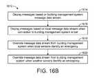
- the processing circuitis configured to cause the display screen to display non-emergency information based on the building data stream, determine whether the weather data stream indicates an emergency weather condition, and override the display of the non-emergency information by causing the display screen to indicate the one or more emergency response directions in response to a determination that the weather data stream indicates the emergency weather condition.
- the one or more emergency response directionsinclude a building map and one or more evacuation directions, wherein the one or more evacuation directions include at least one of one or more directions to a building exit or one or more directions to an emergency shelter in the building.
- causing the display screen to display the one or more emergency response directionsincludes causing the display screen to display the building map and the one or more evacuation directions.
- the one or more emergency response directionsinclude an arrow indicating a route through the building for the user to follow.
- causing the display screen to display the one or more emergency response directionsincludes causing the display screen to display the arrow.
- the arrowincludes a first portion and an arrow border surrounding the first portion.
- the first portionis a first color and the arrow border is a second color different than the first color.
- the display deviceincludes a halo light emitting diode (LED) system including one or more LEDs configured to emit light, a halo diffuser structured around at least a portion of an outer edge of the thermostat, wherein the halo diffuser is configured to diffuse the emitted light of the one or more LEDs around at least the portion of the outer edge of the thermostat, and one or more waveguides, wherein each of the one or more waveguides is configured to transmit light from one of the one or more LEDs to the halo diffuser.
- the display deviceincludes a processing circuit configured to operate the one or more LEDs of the halo LED system to indicate a building emergency condition to a user.
- the processing circuitis configured to receive one or more data streams, determine whether the one or more data streams indicate the building emergency condition, and operate the one or more LEDs of the halo LED system to indicate the building emergency condition to the user.
- the processing circuitis configured to determine a display device condition that requires user input and operate the one or more LEDs of the halo LED system to indicate the display device condition to the user.
- each of the one or more waveguidesare coupled to the halo diffuser at a first end of the one or more waveguides and is proximate to one of the one or more LEDs at a second end of the one or more waveguides.
- the display deviceincludes an enclosure including a front portion and a back portion.
- the halo diffuseris coupled to the front portion and the back portion and is located between the front portion and the back portion.
- the processing circuitis configured to operate the one or more LEDs of the halo LED system to indicate the emergency condition to the user by operating the one or more LEDs in a pattern to indicate one or more emergency response directions to the user prompting the user to perform a user response to the emergency condition.
- operating the one or more LEDs in the pattern to indicate the one or more emergency response directionscomprises activating the one or more LEDs sequentially to indicate an emergency navigation direction.
- the controllerincludes a halo light system including one or more lighting components configured to emit light and a halo diffuser structured around at least a portion of an outer edge of the controller, wherein the halo diffuser is configured to diffuse the emitted light of the one or more lighting components around at least the portion of the outer edge of the controller.
- the controllerincludes a display device configured to display information to a user.
- the controllerincludes a processing circuit configured to receive one or more data streams, determine whether at least one of the one or more data streams indicate a building emergency condition, operate the one or more lighting components of the halo light system to indicate the building emergency condition to the user, and operate the display device to display the building emergency condition to the user.
- a halo LED systemfurther comprises one or more waveguides, wherein each of the one or more waveguides is associated with one of one or more LEDs of the halo LED system, wherein each of the one or more waveguides is configured to transmit light from one of the one or more LEDs to the halo diffuser, wherein each of the one or more waveguides is coupled to the halo diffuser at a first end of the one or more waveguides and is proximate to one of the one or more LEDs at a second end of the one or more waveguides.
- FIG. 1is a drawing of a building equipped with a HVAC system, according to an exemplary embodiment.
- FIG. 2is a drawing of multiple zones and floors of the building of FIG. 1 equipped with control devices, according to an exemplary embodiment.
- FIG. 3is a block diagram of a waterside system that may be used in conjunction with the building of FIGS. 1-2 , according to an exemplary embodiment.
- FIG. 4is a block diagram of an airside system that may be used in conjunction with the building of FIGS. 1-2 , according to an exemplary embodiment.
- FIG. 5is a drawing of the connections of the control device of FIG. 2 and FIG. 4 , according to an exemplary embodiment.
- FIG. 6is a diagram of a communications system located in the building of FIGS. 1 and 2 , according to an exemplary embodiment.
- FIG. 7is a block diagram illustrating the control device of FIGS. 2, 3, and 5 in greater detail, according to an exemplary embodiment.
- FIG. 8is a block diagram illustrating the control device of FIG. 7 connected to three routers located in the building of FIGS. 1 and 2 , according to an exemplary embodiment.
- FIG. 9is a flow diagram illustrating a process for determining the location of a mobile device in the building of FIG. 1 using the plurality of wireless emitters, according to an exemplary embodiment.
- FIG. 10is a drawing of a floorplan of a building with a main control unit in one room and sensor units in other rooms, according to an exemplary embodiments.
- FIG. 11is a diagram illustrating the control device of FIG. 7 receiving occupancy data, according to an exemplary embodiment.
- FIG. 12is a drawing of a building space and an occupant tracking application on the control device of FIG. 7 , according to an exemplary embodiment.
- FIG. 13is a flowchart of operations for controlling zones of a building with the control device of FIG. 11 , according to an exemplary embodiment.
- FIG. 14Ais a flowchart of operations for controlling zones of a building with the control device of FIG. 11 , according to an exemplary embodiment.
- FIG. 14Bis a table of occupant permissions and preferences for the control device of FIG. 7 , according to an exemplary embodiment.
- FIG. 15is a diagram of the control device of FIG. 7 receiving emergency and weather notifications, according to an exemplary embodiment.
- FIG. 16Ais a flowchart of operations for receiving emergency information with the control device of FIG. 7 , according to an exemplary embodiment.
- FIG. 16Bis a flowchart of operations for prioritizing messages and data streams with the control device of FIG. 7 , according to an exemplary embodiment.
- FIG. 17is a drawing of the control device of FIG. 15 displaying an emergency warning, according to an exemplary embodiment.
- FIG. 18is a drawing of the control device of FIG. 15 displaying an evacuation route, according to an exemplary embodiment.
- FIG. 19is a drawing illustrating the control device of FIG. 7 compiling a grocery list, according to an exemplary embodiment.
- FIG. 20is a flowchart of operations for compiling a grocery list with the control device of FIG. 19 , according to an exemplary embodiment.
- FIG. 21is a diagram of the control device of FIG. 7 communicating with health related devices and systems, according to an exemplary embodiment.
- FIG. 22is a drawing of a medical application for the control device of FIG. 21 , according to an exemplary embodiment.
- FIG. 23is a drawing of another medical application for the control device of FIG. 21 , according to an exemplary embodiment.
- FIG. 24is a diagram of the control device of FIG. 21 monitoring the health of an individual, according to an exemplary embodiment.
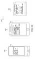
- FIG. 25is a drawing of a medical emergency screen displayed by the control device of FIG. 21 , according to an exemplary embodiment.
- FIG. 26Ais a diagram of the control device of FIG. 7 for hotel use, according to an exemplary embodiment.
- FIG. 26Bis a flow diagram of operations for scheduling hotel reservations with the control device of FIG. 7 , according to an exemplary embodiment.
- FIG. 27is a flow diagram of operations for calling a taxi with the control device of FIG. 7 , according to an exemplary embodiment.
- FIG. 28is a set of drawings of screen displays for selecting room preference of a hotel with the control device of FIG. 7 , according to an exemplary embodiment.
- FIG. 29is a flow diagram of operations for preparing a hotel room for an occupant with the control device of FIG. 7 , according to an exemplary embodiment.
- FIG. 30is a flow diagram of operations for communicating with a front desk with the control device of FIG. 7 , according to an exemplary embodiment.
- FIG. 31is a flow diagram of operations for using a concierge feature of the control device of FIG. 7 , according to an exemplary embodiment.
- FIG. 32is another flow diagram of operations for using a concierge feature of the control device of FIG. 7 , according to an exemplary embodiment.
- FIG. 33is a flow diagram of operations for requesting hotel accommodations with the control device of FIG. 7 , according to an exemplary embodiment.
- FIG. 34is a flow diagram of operations for checking out of a hotel room with the control device of FIG. 7 , according to an exemplary embodiment.
- FIG. 35is a block diagram illustrating the payment module of FIG. 7 in greater detail, according to an exemplary embodiment.
- FIG. 36is a block diagram illustrating the input device of FIG. 7 in greater detail, according to an exemplary embodiment.
- FIG. 37is a drawing illustrating the control device of FIG. 7 receiving a payment, according to an exemplary embodiment.
- FIG. 38is another drawing illustrating the control device of FIG. 7 receiving a payment, according to an exemplary embodiment.
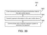
- FIG. 39is a flowchart of operations for processing a transaction with the control device of FIG. 7 , according to an exemplary embodiment.
- FIG. 40is a block diagram of a communications system located in the building of FIG. 1 , according to an exemplary embodiment.
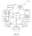
- FIG. 41is a block diagram of a communications system located in the building of FIG. 40 where the display devices are communicating ad hoc, according to an exemplary embodiment.
- FIG. 42is a block diagram illustrating the display device of FIGS. 40-41 in greater detail, according to an exemplary embodiment.
- FIG. 43is a block diagram illustrating another embodiment of the display device of FIGS. 40-41 in greater detail, according to an exemplary embodiment.
- FIG. 44is a block diagram illustrating another embodiment of the display device of FIGS. 40-41 in greater detail, according to an exemplary embodiment.
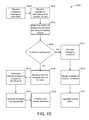
- FIG. 45is a flow diagram of operations for prioritizing directions and displaying the directions on the display device of FIGS. 40-44 , according to an exemplary embodiment.
- FIG. 46is a flow diagram of operations for handing off directions between multiple display devices of FIGS. 40-44 , according to an exemplary embodiment.
- FIG. 47is a flow diagram of operations for detaching the display device of FIGS. 4-8 from the wall in an emergency situation, according to an exemplary embodiment.
- FIG. 48is a drawing of the display device of FIGS. 40-44 displaying an emergency warning, according to an exemplary embodiment.
- FIG. 49is a drawing of the display device of FIGS. 40-44 displaying a building event notification, according to an exemplary embodiment.
- FIG. 50is a drawing of the display device of FIGS. 40-44 displaying a route notification, according to an exemplary embodiment.
- FIG. 51is a drawing of the display device of FIGS. 40-44 displaying a handicap route notification, according to an exemplary embodiment.
- FIG. 52is a drawing of the display device of FIGS. 40-44 displaying an emergency direction, according to an exemplary embodiment.
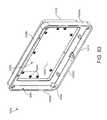
- FIG. 53is an isometric view of a display device, according to some embodiments.
- FIG. 54is a side view of the display device of FIG. 53 , according to some embodiments.
- FIG. 55is a rear view of the display device of FIG. 53 , according to some embodiments.
- FIG. 56is a rear elevated view of the display device of FIG. 53 , according to some embodiments.
- FIG. 57is a top view of the display device of FIG. 53 , according to some embodiments.
- FIG. 58is a top view of the display device of FIG. 53 , according to some embodiments.
- FIG. 59is a top view of the display device of FIG. 53 , according to some embodiments.
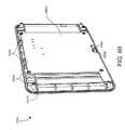
- FIG. 60is a rear elevated view of a front portion of the display device of FIG. 53 , according to some embodiments.
- FIG. 61is a front elevated view of the front portion of FIG. 60 , according to some embodiments.
- FIG. 62is a front isometric view of the front portion of FIG. 60 , according to some embodiments.
- FIG. 63is an isometric view of a rear portion of the display device of FIG. 53 , shown to include an LED board, according to some embodiments.
- FIG. 64is a front view of the LED board of FIG. 63 , according to some embodiments.
- FIG. 65is a front view of the LED board of FIG. 63 , according to some embodiments.
- FIG. 66is a side view of a portion of the display device of FIG. 53 , shown to include a halo, according to some embodiments.
- FIG. 67is a front view of the halo of FIG. 66 , according to some embodiments.
- FIG. 68is a rear elevated view of the halo of FIG. 66 , shown to include light guiding elements, according to some embodiments.
- FIG. 69is an elevated view of one of the light guiding elements of FIG. 68 , according to some embodiments.
- FIG. 70is a side view of one of the light guiding elements of FIG. 68 , shown receiving light from an LED, according to some embodiments.
- FIG. 71is a side view of the halo of FIG. 66 , shown to include light guiding elements receiving light emitted by LEDs and guiding the emitted light, according to some embodiments.
- FIG. 72is a block diagram of an LED controller, according to some embodiments.
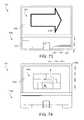
- FIG. 73is a schematic drawing of the control device of FIG. 2 including a halo diffusing light around a base portion of the control device, according to an exemplary embodiment.
- FIG. 74is a schematic drawing of the control device of FIG. 2 including a halo diffusing light around a display screen of the control device, according to an exemplary embodiment.
- FIG. 75is a block diagram illustrating the control device of FIGS. 73-74 in greater detail for operating the halos of FIGS. 73-74 to indicate emergency conditions, according to an exemplary embodiment.
- FIG. 76is a flow diagram of a process of operating the halos of FIGS. 73-74 to indicate emergency conditions by the control device of FIGS. 73-74 , according to an exemplary embodiment.
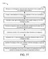
- FIG. 77is a flow diagram of a process for displaying non-emergency information of a first data stream and overriding the display of the non-emergency information of the first data stream based on a second data stream that can be performed by the control device of FIGS. 73-74 , according to an exemplary embodiment.
- a user control deviceis shown, according to various exemplary embodiments.
- the thermostat described hereinmay be used in any HVAC system, room, environment, or system within which it is desired to control and/or observe environmental conditions (e.g., temperature, humidity, etc.).
- a thermostatmay be adjusted by a user to control the temperature of a system.
- the user control deviceis intended to provide the user with an ability to function as a connected smart hub.
- the thermostatprovides a desirable user interface for other environmental controls because of its known fixed location within a space.
- the user control deviceis intended to be more personal, more efficient, and more aware than traditional thermostats.
- the user control devicecollects data about a space and the occupants of the space with various sensors (e.g., temperature sensors, humidity sensors, acoustic sensors, optical sensors, gas and other chemical sensors, biometric sensors, motion sensors, etc.) and user inputs.
- the user control devicemay utilize data collected from a single room, multiple rooms, an entire building, or multiple buildings.
- the datamay be analyzed locally by the user control device or may be uploaded to a remote computing system and/or the cloud for further analysis and processing.
- FIGS. 1-4an exemplary building management system (BMS) and HVAC system in which the systems and methods of the present disclosure may be implemented are shown, according to an exemplary embodiment.
- BMSbuilding management system
- HVAC systemHVAC system
- FIG. 1a perspective view of a building 10 is shown.
- Building 10is served by a BMS.
- a BMSis, in general, a system of devices configured to control, monitor, and manage equipment in or around a building or building area.
- a BMScan include, for example, a HVAC system, a security system, a lighting system, a fire alerting system, any other system that is capable of managing building functions or devices, or any combination thereof.
- HVAC system 100may include a plurality of HVAC devices (e.g., heaters, chillers, air handling units, pumps, fans, thermal energy storage, etc.) configured to provide heating, cooling, ventilation, or other services for building 10 .
- HVAC system 100is shown to include a waterside system 120 and an airside system 130 .
- Waterside system 120may provide a heated or chilled fluid to an air handling unit of airside system 130 .
- Airside system 130may use the heated or chilled fluid to heat or cool an airflow provided to building 10 .
- An exemplary waterside system and airside system which may be used in HVAC system 100are described in greater detail with reference to FIGS. 2-3 .
- HVAC system 100is shown to include a chiller 102 , a boiler 104 , and a rooftop air handling unit (AHU) 106 .
- Waterside system 120may use boiler 104 and chiller 102 to heat or cool a working fluid (e.g., water, glycol, etc.) and may circulate the working fluid to AHU 106 .
- the HVAC devices of waterside system 120may be located in or around building 10 (as shown in FIG. 1 ) or at an offsite location such as a central plant (e.g., a chiller plant, a steam plant, a heat plant, etc.).
- the working fluidmay be heated in boiler 104 or cooled in chiller 102 , depending on whether heating or cooling is required in building 10 .
- Boiler 104may add heat to the circulated fluid, for example, by burning a combustible material (e.g., natural gas) or using an electric heating element.
- Chiller 102may place the circulated fluid in a heat exchange relationship with another fluid (e.g., a refrigerant) in a heat exchanger (e.g., an evaporator) to absorb heat from the circulated fluid.
- the working fluid from chiller 102 and/or boiler 104may be transported to AHU 106 via piping 108 .
- AHU 106may place the working fluid in a heat exchange relationship with an airflow passing through AHU 106 (e.g., via one or more stages of cooling coils and/or heating coils).
- the airflowmay be, for example, outside air, return air from within building 10 , or a combination of both.
- AHU 106may transfer heat between the airflow and the working fluid to provide heating or cooling for the airflow.
- AHU 106may include one or more fans or blowers configured to pass the airflow over or through a heat exchanger containing the working fluid. The working fluid may then return to chiller 102 or boiler 104 via piping 110 .
- Airside system 130may deliver the airflow supplied by AHU 106 (i.e., the supply airflow) to building 10 via air supply ducts 112 and may provide return air from building 10 to AHU 106 via air return ducts 114 .
- airside system 130includes multiple variable air volume (VAV) units 116 .
- VAVvariable air volume
- airside system 130is shown to include a separate VAV unit 116 on each floor or zone of building 10 .
- VAV units 116may include dampers or other flow control elements that can be operated to control an amount of the supply airflow provided to individual zones of building 10 .
- airside system 130delivers the supply airflow into one or more zones of building 10 (e.g., via supply ducts 112 ) without using intermediate VAV units 116 or other flow control elements.
- AHU 106may include various sensors (e.g., temperature sensors, pressure sensors, etc.) configured to measure attributes of the supply airflow.
- AHU 106may receive input from sensors located within AHU 106 and/or within the building zone and may adjust the flow rate, temperature, or other attributes of the supply airflow through AHU 106 to achieve setpoint conditions for the building zone.
- building 10is shown in greater detail, according to an exemplary embodiment.
- Building 10may have multiple zones.
- building 10has zones, 202 , 204 , 206 , 208 , 210 , and 212 .
- the zoneseach correspond to a separate floor.
- the zones of building 10may be rooms, sections of a floor, multiple floors, etc.
- Each zonemay have a corresponding control device 214 .
- control device 214is at least one of a thermostat, a sensor, a controller, a display device, a concierge device, a medical monitor device, etc. Control device 214 may take input from users.
- control device 214can cause music and/or building announcements to be played in one or more of zones 202 - 212 , cause the temperature and/or humidity to be regulated in one or more of zones 202 - 212 , and/or any other control action.
- control device 214can monitor the health of an occupant 216 of building 10 . In some embodiments, control device 214 monitors heat signatures, heartrates, and any other information that can be collected from cameras, medical devices, and/or any other health related sensor.
- building 10has wireless transmitters 218 in each or some of zones 202 - 212 .
- the wireless transmitters 218may be routers, coordinators, and/or any other device broadcasting radio waves. In some embodiments, wireless transmitters 218 form a Wi-Fi network, a Zigbee network, a Bluetooth network, and/or any other kind of network.
- occupant 216has a mobile device that can communicate with wireless transmitters 218 .
- Control device 214may use the signal strengths between the mobile device of occupant 216 and the wireless transmitters 218 to determine what zone the occupant is in.
- control device 214causes temperature setpoints, music and/or other control actions to follow occupant 216 as the occupant 216 moves from one zone to another zone (i.e., from one floor to another floor).
- control devices 214are connected to a building management system, a weather server, and/or a building emergency sensor(s). In some embodiments, control devices 214 may receive emergency notifications from the building management system, the weather server, and/or the building emergency sensor(s). Based on the nature of the emergency, control devices 214 may give directions to an occupant of the building. In some embodiments, the direction may be to respond to an emergency (e.g., call the police, hide and turn the lights off, etc.) In various embodiments, the directions given to the occupant (e.g., occupant 216 ) may be navigation directions. For example, zone 212 may be a safe zone with no windows an individual (e.g., occupant 216 ). If control devices 214 determines that there are high winds around building 10 , the control device 214 may direct occupants of zones 202 - 210 to zone 212 if zone 212 has no windows.
- zone 212may be a safe zone with no windows an individual (e.g., occupant 216 ).
- waterside system 300may supplement or replace waterside system 120 in HVAC system 100 or may be implemented separate from HVAC system 100 .
- waterside system 300may include a subset of the HVAC devices in HVAC system 100 (e.g., boiler 104 , chiller 102 , pumps, valves, etc.) and may operate to supply a heated or chilled fluid to AHU 106 .
- the HVAC devices of waterside system 300may be located within building 10 (e.g., as components of waterside system 120 ) or at an offsite location such as a central plant.
- waterside system 300is shown as a central plant having a plurality of subplants 302 - 312 .
- Subplants 302 - 312are shown to include a heater subplant 302 , a heat recovery chiller subplant 304 , a chiller subplant 306 , a cooling tower subplant 308 , a hot thermal energy storage (TES) subplant 310 , and a cold thermal energy storage (TES) subplant 312 .
- Subplants 302 - 312consume resources (e.g., water, natural gas, electricity, etc.) from utilities to serve the thermal energy loads (e.g., hot water, cold water, heating, cooling, etc.) of a building or campus.
- resourcese.g., water, natural gas, electricity, etc.
- heater subplant 302may be configured to heat water in a hot water loop 314 that circulates the hot water between heater subplant 302 and building 10 .
- Chiller subplant 306may be configured to chill water in a cold water loop 316 that circulates the cold water between chiller subplant 306 building 10 .
- Heat recovery chiller subplant 304may be configured to transfer heat from cold water loop 316 to hot water loop 314 to provide additional heating for the hot water and additional cooling for the cold water.
- Condenser water loop 318may absorb heat from the cold water in chiller subplant 306 and reject the absorbed heat in cooling tower subplant 308 or transfer the absorbed heat to hot water loop 314 .
- Hot TES subplant 310 and cold TES subplant 312may store hot and cold thermal energy, respectively, for subsequent use.
- Hot water loop 314 and cold water loop 316may deliver the heated and/or chilled water to air handlers located on the rooftop of building 10 (e.g., AHU 106 ) or to individual floors or zones of building 10 (e.g., VAV units 116 ).
- the air handlerspush air past heat exchangers (e.g., heating coils or cooling coils) through which the water flows to provide heating or cooling for the air.
- the heated or cooled airmay be delivered to individual zones of building 10 to serve the thermal energy loads of building 10 .
- the waterthen returns to subplants 302 - 312 to receive further heating or cooling.
- subplants 302 - 312are shown and described as heating and cooling water for circulation to a building, it is understood that any other type of working fluid (e.g., glycol, CO2, etc.) may be used in place of or in addition to water to serve the thermal energy loads. In other embodiments, subplants 302 - 312 may provide heating and/or cooling directly to the building or campus without requiring an intermediate heat transfer fluid. These and other variations to waterside system 300 are within the teachings of the present disclosure.
- working fluide.g., glycol, CO2, etc.
- Each of subplants 302 - 312may include a variety of equipment configured to facilitate the functions of the subplant.
- heater subplant 302is shown to include a plurality of heating elements 320 (e.g., boilers, electric heaters, etc.) configured to add heat to the hot water in hot water loop 314 .
- Heater subplant 302is also shown to include several pumps 322 and 324 configured to circulate the hot water in hot water loop 314 and to control the flow rate of the hot water through individual heating elements 320 .
- Chiller subplant 306is shown to include a plurality of chillers 332 configured to remove heat from the cold water in cold water loop 316 .
- Chiller subplant 306is also shown to include several pumps 334 and 336 configured to circulate the cold water in cold water loop 316 and to control the flow rate of the cold water through individual chillers 332 .
- Heat recovery chiller subplant 304is shown to include a plurality of heat recovery heat exchangers 326 (e.g., refrigeration circuits) configured to transfer heat from cold water loop 316 to hot water loop 314 .
- Heat recovery chiller subplant 304is also shown to include several pumps 328 and 330 configured to circulate the hot water and/or cold water through heat recovery heat exchangers 326 and to control the flow rate of the water through individual heat recovery heat exchangers 226 .
- Cooling tower subplant 208is shown to include a plurality of cooling towers 338 configured to remove heat from the condenser water in condenser water loop 318 .
- Cooling tower subplant 308is also shown to include several pumps 340 configured to circulate the condenser water in condenser water loop 318 and to control the flow rate of the condenser water through individual cooling towers 338 .
- Hot TES subplant 310is shown to include a hot TES tank 342 configured to store the hot water for later use.
- Hot TES subplant 310may also include one or more pumps or valves configured to control the flow rate of the hot water into or out of hot TES tank 342 .
- Cold TES subplant 312is shown to include cold TES tanks 344 configured to store the cold water for later use.
- Cold TES subplant 312may also include one or more pumps or valves configured to control the flow rate of the cold water into or out of cold TES tanks 344 .
- one or more of the pumps in waterside system 300(e.g., pumps 322 , 324 , 328 , 330 , 334 , 336 , and/or 340 ) or pipelines in waterside system 300 include an isolation valve associated therewith. Isolation valves may be integrated with the pumps or positioned upstream or downstream of the pumps to control the fluid flows in waterside system 300 .
- waterside system 300may include more, fewer, or different types of devices and/or subplants based on the particular configuration of waterside system 300 and the types of loads served by waterside system 300 .
- airside system 400is shown to include an economizer-type air handling unit (AHU) 402 .
- Economizer-type AHUsvary the amount of outside air and return air used by the air handling unit for heating or cooling.
- AHU 402may receive return air 404 from building zone 406 via return air duct 408 and may deliver supply air 410 to building zone 406 via supply air duct 612 .
- AHU 402is a rooftop unit located on the roof of building 10 (e.g., AHU 402 as shown in FIG. 1 ) or otherwise positioned to receive both return air 404 and outside air 414 .
- AHU 402may be configured to operate exhaust air damper 416 , mixing damper 418 , and outside air damper 420 to control an amount of outside air 414 and return air 404 that combine to form supply air 410 . Any return air 404 that does not pass through mixing damper 418 may be exhausted from AHU 402 through exhaust damper 416 as exhaust air 422 .
- Each of dampers 416 - 420may be operated by an actuator.
- exhaust air damper 416may be operated by actuator 424
- mixing damper 418may be operated by actuator 426
- outside air damper 420may be operated by actuator 428 .
- Actuators 424 - 428may communicate with an AHU controller 430 via a communications link 432 .
- Actuators 424 - 428may receive control signals from AHU controller 430 and may provide feedback signals to AHU controller 430 .
- Feedback signalsmay include, for example, an indication of a current actuator or damper position, an amount of torque or force exerted by the actuator, diagnostic information (e.g., results of diagnostic tests performed by actuators 424 - 428 ), status information, commissioning information, configuration settings, calibration data, and/or other types of information or data that may be collected, stored, or used by actuators 424 - 428 .
- diagnostic informatione.g., results of diagnostic tests performed by actuators 424 - 428
- status informatione.g., commissioning information
- configuration settingse.g., configuration settings, calibration data, and/or other types of information or data that may be collected, stored, or used by actuators 424 - 428 .
- AHU controller 430may be an economizer controller configured to use one or more control algorithms (e.g., state-based algorithms, extremum seeking control (ESC) algorithms, proportional-integral (PI) control algorithms, proportional-integral-derivative (PID) control algorithms, model predictive control (MPC) algorithms, feedback control algorithms, etc.) to control actuators 424 - 428 .
- control algorithmse.g., state-based algorithms, extremum seeking control (ESC) algorithms, proportional-integral (PI) control algorithms, proportional-integral-derivative (PID) control algorithms, model predictive control (MPC) algorithms, feedback control algorithms, etc.
- AHU 402is shown to include a cooling coil 434 , a heating coil 436 , and a fan 438 positioned within supply air duct 612 .
- Fan 438may be configured to force supply air 410 through cooling coil 434 and/or heating coil 436 and provide supply air 410 to building zone 406 .
- AHU controller 430may communicate with fan 438 via communications link 440 to control a flow rate of supply air 410 .
- AHU controller 430controls an amount of heating or cooling applied to supply air 410 by modulating a speed of fan 438 .
- Cooling coil 434may receive a chilled fluid from waterside system 200 (e.g., from cold water loop 316 ) via piping 442 and may return the chilled fluid to waterside system 200 via piping 444 .
- Valve 446may be positioned along piping 442 or piping 444 to control a flow rate of the chilled fluid through cooling coil 474 .
- cooling coil 434includes multiple stages of cooling coils that can be independently activated and deactivated (e.g., by AHU controller 430 , by BMS controller 466 , etc.) to modulate an amount of cooling applied to supply air 410 .
- Heating coil 436may receive a heated fluid from waterside system 200 (e.g., from hot water loop 314 ) via piping 448 and may return the heated fluid to waterside system 200 via piping 450 .
- Valve 452may be positioned along piping 448 or piping 450 to control a flow rate of the heated fluid through heating coil 436 .
- heating coil 436includes multiple stages of heating coils that can be independently activated and deactivated (e.g., by AHU controller 430 , by BMS controller 466 , etc.) to modulate an amount of heating applied to supply air 410 .
- valves 446 and 452may be controlled by an actuator.
- valve 446may be controlled by actuator 454 and valve 452 may be controlled by actuator 456 .
- Actuators 454 - 456may communicate with AHU controller 430 via communications links 458 - 460 .
- Actuators 454 - 456may receive control signals from AHU controller 430 and may provide feedback signals to controller 430 .
- AHU controller 430receives a measurement of the supply air temperature from a temperature sensor 462 positioned in supply air duct 612 (e.g., downstream of cooling coil 434 and/or heating coil 436 ).
- AHU controller 430may also receive a measurement of the temperature of building zone 406 from a temperature sensor 464 located in building zone 406 .
- AHU controller 430operates valves 446 and 452 via actuators 454 - 456 to modulate an amount of heating or cooling provided to supply air 410 (e.g., to achieve a set point temperature for supply air 410 or to maintain the temperature of supply air 410 within a set point temperature range).
- the positions of valves 446 and 452affect the amount of heating or cooling provided to supply air 410 by cooling coil 434 or heating coil 436 and may correlate with the amount of energy consumed to achieve a desired supply air temperature.
- AHU controller 430may control the temperature of supply air 410 and/or building zone 406 by activating or deactivating coils 434 - 436 , adjusting a speed of fan 438 , or a combination of both.
- airside system 400is shown to include a building management system (BMS) controller 466 and a control device 214 .
- BMS controller 466may include one or more computer systems (e.g., servers, supervisory controllers, subsystem controllers, etc.) that serve as system level controllers, application or data servers, head nodes, or master controllers for airside system 400 , waterside system 200 , HVAC system 100 , and/or other controllable systems that serve building 10 .
- computer systemse.g., servers, supervisory controllers, subsystem controllers, etc.
- application or data serverse.g., application or data servers, head nodes, or master controllers for airside system 400 , waterside system 200 , HVAC system 100 , and/or other controllable systems that serve building 10 .
- BMS controller 466may communicate with multiple downstream building systems or subsystems (e.g., HVAC system 100 , a security system, a lighting system, waterside system 200 , etc.) via a communications link 470 according to like or disparate protocols (e.g., LON, BACnet, etc.).
- AHU controller 430 and BMS controller 466may be separate (as shown in FIG. 4 ) or integrated.
- AHU controller 430may be a software module configured for execution by a processor of BMS controller 466 .
- AHU controller 430receives information from BMS controller 466 (e.g., commands, set points, operating boundaries, etc.) and provides information to BMS controller 466 (e.g., temperature measurements, valve or actuator positions, operating statuses, diagnostics, etc.).
- BMS controller 466may provide BMS controller 466 with temperature measurements from temperature sensors 462 - 464 , equipment on/off states, equipment operating capacities, and/or any other information that can be used by BMS controller 466 to monitor or control a variable state or condition within building zone 406 .
- Control device 214may include one or more of the user control devices.
- Control device 214may include one or more human-machine interfaces or client interfaces (e.g., graphical user interfaces, reporting interfaces, text-based computer interfaces, client-facing web services, web servers that provide pages to web clients, etc.) for controlling, viewing, or otherwise interacting with HVAC system 100 , its subsystems, and/or devices.
- Control device 214may be a computer workstation, a client terminal, a remote or local interface, or any other type of user interface device.
- Control device 214may be a stationary terminal or a mobile device.
- control device 214may be a desktop computer, a computer server with a user interface, a laptop computer, a tablet, a smartphone, a PDA, or any other type of mobile or non-mobile device.
- Control device 214may communicate with BMS controller 466 and/or AHU controller 430 via communications link 472 .
- control device 214is shown as a connected smart hub or private area network (PAN), according to some embodiments.
- Control device 214may include a variety of sensors and may be configured to communicate with a variety of external systems or devices.
- control device 214may include temperature sensors 502 , speakers 504 , leak detection system 508 , health monitoring sensors 510 , humidity sensors 514 , occupancy sensors 516 , light detection sensors 518 , proximity sensor 520 , carbon dioxide sensors 522 , or any of a variety of other sensors.
- control device 214may receive input from external sensors configured to measure such variables.
- the external sensorsmay not communicate over a PAN network but may communicate with control device 214 via an IP based network and/or the Internet.
- speakers 504are located locally as a component of control device 214 . Speakers 504 may be low power speakers used for playing audio to the immediate occupant of control device 214 and/or occupants of the zone in which control device 214 is located. In some embodiments, speakers 504 may be remote speakers connected to control device 214 via a network. In some embodiments, speakers 504 are a building audio system, an emergency alert system, and/or alarm system configured to broadcast building wide and/or zone messages or alarms.
- Control device 214may communicate with a remote camera 506 , a shade control system 512 , a leak detection system 508 , a HVAC system, or any of a variety of other external systems or devices which may be used in a home automation system or a building automation system.
- Control device 214may provide a variety of monitoring and control interfaces to allow a user to control all of the systems and devices connected to control device 214 . Exemplary user interfaces and features of control device 214 are described in greater detail below.
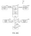
- System 600can be implemented in a building (e.g. building 10 ) and is shown to include control device 214 , network 602 , healthcare sensor(s) 604 , building emergency sensor(s) 606 , weather server(s) 608 , building management system 610 , and user device 612 .
- System 600connects devices, systems, and servers via network 602 so that building information, HVAC controls, emergency information, navigation directions, and other information can be passed between devices (e.g., control device 214 , user device 612 , and/or building emergency sensor(s) 606 and servers and systems (e.g., weather server(s) 608 and/or building management system 610 ).
- control device 214is connected to speakers 504 as described with reference to FIG. 5 .
- network 602communicatively couples the devices, systems, and servers of system 600 .
- network 602is at least one of and/or a combination of a Wi-Fi network, a wired Ethernet network, a Zigbee network, and a Bluetooth network.
- Network 602may be a local area network or a wide area network (e.g., the Internet, a building WAN, etc.) and may use a variety of communications protocols (e.g., BACnet, IP, LON, etc.)
- Network 602may include routers, modems, and/or network switches.
- control device 214is configured to receive emergency information, navigation directions, occupant information, concierge information, and any other information via network 602 .
- the informationis received from building management system 610 via network 602 .
- the informationis received from the Internet via network 602 .
- control device 214is at least one of or a combination of a thermostat, a humidistat, a light controller, and any other wall mounted and/or hand held device.
- control device 214is connected to building emergency sensor(s) 606 .
- building emergency sensor(s) 606are sensors which detect building emergencies.
- Building emergency sensor(s) 606may be smoke detectors, carbon monoxide detectors, carbon dioxide detectors (e.g., carbon dioxide sensors 522 ), an emergency button (e.g., emergency pull handles, panic buttons, a manual fire alarm button and/or handle, etc.) and/or any other emergency sensor.
- the emergency sensor(s)include actuators.
- the actuatorsmay be building emergency sirens and/or building audio speaker systems (e.g., speakers 504 ), automatic door and/or window control (e.g., shade control system 512 ), and any other actuator used in a building.
- control device 214may be communicatively coupled to weather server(s) 608 via network 602 .
- the control device 214may be configured to receive weather alerts (e.g., high and low daily temperature, five-day forecast, thirty-day forecast, etc.) from weather server(s) 608 .
- Control device 214may be configured to receive emergency weather alerts (e.g., flood warnings, fire warnings, thunder storm warnings, winter storm warnings, etc.)
- control device 214may be configured to display emergency warnings via a user interface of control device 214 when control device 214 receives an emergency weather alert from weather server(s) 608 .
- the control device 214may be configured to display emergency warnings based on the data received from building emergency sensor(s) 606 .
- the control device 214may cause a siren (e.g., speakers 504 and/or building emergency sensor(s) 606 ) to alert occupants of the building of an emergency, cause all doors to become locked and/or unlocked, cause an advisory message be broadcast through the building, and control any other actuator or system necessary for responding to a building emergency.
- a sirene.g., speakers 504 and/or building emergency sensor(s) 606
- control device 214is configured to communicate with building management system 610 via network 602 .
- Control device 214may be configured to transmit environmental setpoints (e.g., temperature setpoint, humidity setpoint, etc.) to building management system 610 .
- building management system 610may be configured to cause zones of a building (e.g., building 10 ) to be controlled to the setpoint received from control device 214 .
- building management system 610may be configured to control the lighting of a building.
- building management system 610may be configured to transmit emergency information to control device 214 .
- the emergency informationis a notification of a shooter lockdown, a tornado warning, a flood warning, a thunderstorm warning, and/or any other warning.
- building management system 610is connected to various weather servers or other web servers from which building management system 610 receives emergency warning information.
- building management systemis a computing system of a hotel. Building management system 610 may keep track of hotel occupancy, may relay requests to hotel staff, and/or perform any other functions of a hotel computing system.
- Control device 214is configured to communicate with user device 612 via network 602 .
- user device 612is a smartphone, a tablet, a laptop computer, and/or any other mobile and/or stationary computing device.
- user device 612communicates calendar information to control device 214 .
- the calendar informationis stored and/or entered by a user into a calendar application.
- calendar applicationis at least one of Outlook, Google Calendar, Fantastical, Shifts, CloudCal, DigiCal, and/or any other calendar application.
- control device 214receives calendar information from the calendar application such as times and locations of appointments, times and locations of meetings, and/or any other information.
- Control device 214may be configured to display building map direction to a user associated with user device 612 and/or any other information.
- a usermay press a button on a user interface of control device 214 indicating a building emergency.
- the usermay be able to indicate the type of emergency (e.g., fire, flood, active shooter, etc.)
- Control device 214may communicate an alert to building management system 610 , user device 612 , and any other device, system, and/or server.
- control device 214is communicably coupled to healthcare sensor(s) 604 via network 602 .
- control deviceis configured to monitor healthcare sensor(s) 604 collecting data for occupants of a building (e.g., building 10 ) and determine health metrics for the occupants based on the data received from the healthcare sensor(s) 604 .
- healthcare sensor(s) 604are one or more smart wrist bands, pacemakers, insulin pumps, and/or any other medical device. The health metrics may be determined based on heart rates, insulin levels, and/or any other biological and/or medical data.
- Control device 214is shown to include a variety of user interface devices 702 and sensors 714 .
- User interface devices 702may be configured to receive input from a user and provide output to a user in various forms.
- user interface devices 702are shown to include electronic display 706 , an electronic display 706 , ambient lighting 708 , speakers 710 (e.g., speakers 504 ), and input device 712 .
- user interface devices 702include a microphone configured to receive voice commands from a user, a keyboard or buttons, switches, dials, or any other user-operable input devices.
- user interface devices 702may include any type of device configured to receive input from a user and/or provide an output to a user in any of a variety of forms (e.g., touch, text, video, graphics, audio, vibration, etc.).
- Sensors 714may be configured to measure a variable state or condition of the environment in which control device 214 is installed.
- sensors 714are shown to include a temperature sensor 716 , a humidity sensor 718 , an air quality sensor 720 , a proximity sensor 722 , a camera 724 , a microphone 726 , a light sensor 728 , and a vibration sensor 730 .
- Air quality sensor 720may be configured to measure any of a variety of air quality variables such as oxygen level, carbon dioxide level, carbon monoxide level, allergens, pollutants, smoke, etc.
- Proximity sensor 722may include one or more sensors configured to detect the presence of people or devices proximate to control device 214 .
- proximity sensor 722may include a near-field communications (NFC) sensor, a radio frequency identification (RFID) sensor, a Bluetooth sensor, a capacitive proximity sensor, a biometric sensor, or any other sensor configured to detect the presence of a person or device.
- Camera 724may include a visible light camera, a motion detector camera, an infrared camera, an ultraviolet camera, an optical sensor, or any other type of camera.
- Light sensor 728may be configured to measure ambient light levels.
- Vibration sensor 730may be configured to measure vibrations from earthquakes or other seismic activity at the location of control device 214 .
- control device 214is shown to include a communications interface 732 and a processing circuit 734 .
- Communications interface 732may include wired or wireless interfaces (e.g., jacks, antennas, transmitters, receivers, transceivers, wire terminals, etc.) for conducting data communications with various systems, devices, or networks.
- communications interface 732may include an Ethernet card and port for sending and receiving data via an Ethernet-based communications network and/or a Wi-Fi transceiver for communicating via a wireless communications network.
- Communications interface 732may be configured to communicate via local area networks or wide area networks (e.g., the Internet, a building WAN, etc.) and may use a variety of communications protocols (e.g., BACnet, IP, LON, etc.).
- Communications interface 732may include a network interface configured to facilitate electronic data communications between control device 214 and various external systems or devices (e.g., network 602 , building management system 610 , HVAC equipment 738 , user device 612 , etc.)
- control device 214may receive information from building management system 610 or HVAC equipment 738 indicating one or more measured states of the controlled building (e.g., temperature, humidity, electric loads, etc.) and one or more states of the HVAC equipment 738 (e.g., equipment status, power consumption, equipment availability, etc.).
- HVAC equipment 738may be lighting systems, building systems, actuators, chillers, heaters, and/or any other building equipment and/or system.
- Communications interface 732may receive inputs from building management system 610 or HVAC equipment 738 and may provide operating parameters (e.g., on/off decisions, set points, etc.) to building management system 610 or HVAC equipment 738 .
- the operating parametersmay cause building management system 610 to activate, deactivate, or adjust a set point for various types of home equipment or building equipment in communication with control device 214 .
- Processing circuit 734is shown to include a processor 740 and memory 742 .
- Processor 740may be a general purpose or specific purpose processor, an application specific integrated circuit (ASIC), one or more field programmable gate arrays (FPGAs), a group of processing components, or other suitable processing components.
- ASICapplication specific integrated circuit
- FPGAsfield programmable gate arrays
- Processor 740may be configured to execute computer code or instructions stored in memory 742 or received from other computer readable media (e.g., CDROM, network storage, a remote server, etc.).
- Memory 742may include one or more devices (e.g., memory units, memory devices, storage devices, etc.) for storing data and/or computer code for completing and/or facilitating the various processes described in the present disclosure.
- Memory 742may include random access memory (RAM), read-only memory (ROM), hard drive storage, temporary storage, non-volatile memory, flash memory, optical memory, or any other suitable memory for storing software objects and/or computer instructions.
- Memory 742may include database components, object code components, script components, or any other type of information structure for supporting the various activities and information structures described in the present disclosure.
- Memory 742may be communicably connected to processor 740 via processing circuit 734 and may include computer code for executing (e.g., by processor 740 ) one or more processes described herein.
- memory 742is shown to include a voice command module 744 , a building module 746 , a voice control module 748 , a payment module 758 , a hotel module 750 , a healthcare module 752 , an occupancy module 754 , and an emergency module 756 .
- the functions of some of these modulesis described in greater detail below.
- voice command module 744is configured to receive audio data from microphone 726 . Voice command module 744 may be configured to translate audio data into spoken words. In some embodiments, voice command module 744 may be configured to perform Internet searches based on the spoken words via network 602 . In various embodiments, voice command module 744 may send requests to building management system 610 based on the spoken words.
- System 800can be implemented in a building space (e.g., building 10 ) to determine the occupancy of the building space based on Wi-Fi router connections and signal strengths.
- System 800is shown to include building management system 610 , control device 214 , network 602 , routers 804 - 808 , and user device 612 .
- building management system 610operates the building space as described in FIGS. 1-4 .
- control device 214operates the building space as described in FIGS. 1-4 .
- Building management system 610is shown to be connected to control device 214 and routers 804 - 808 .
- network 602is at least one of and/or a combination of a Wi-Fi network, a wired Ethernet network, a Zigbee network, and a Bluetooth network.
- Network 602may be a local area network or a wide area network (e.g., the Internet, a building WAN, etc.) and may use a variety of communications protocols (e.g., BACnet, IP, LON, etc.).
- Building management system 610may include an application server.
- the application servermay be a remote server and may be hosted at a remote location.
- the application servermay be configured to provide a web-based presence for users and/or building administrators to access information regarding occupancy of the building.
- the application serverallows users and/or building administrators to view data pertaining to the number of users in the building space and their respective locations.
- the application servermay communicate with user device 612 through routers 804 - 808 or may communicate to user device 612 via mobile data (e.g. 1G, 2G, 3G, LTE, etc.).
- the application serverintegrates a building facility web application with the determined number and location of occupants.
- the building facility applicationmay control room, zone, building, and campus lighting, booking, public service announcements and other features of a building facility.
- the building facility web applicationmay identify a user when a device associated with the user (e.g., user device 612 ) is detected in a room, zone, building and/or campus based on wireless signal strengths.
- the building facility web applicationmay automatically login the identified user with the building web facility application.
- a user that has been logged inmay be able to change lighting, environmental setpoints and any other adjustable building facility web application feature via user device 612 .
- the building facility web applicationmay automatically adjust lighting and environmental setpoints to preferred settings of the identified and logged in user.
- Routers 804 - 808may be installed for the specific purpose of determining user occupancy or may be existing routers in a wireless building network. In some embodiments, each router may have a unique ID. In FIG. 8 , router 804 has the ID B 1 , router 806 has the ID A 1 , and router 808 has the ID C 1 . Routers 804 - 808 may connect user device 612 to the Internet and/or control device 214 through network 602 . Although only three routers 804 - 808 are shown in FIG. 8 , it is contemplated that system 800 can include any number of routers located in the building space.
- Routers 804 - 808can be configured to emit, receive, sense, relay, or otherwise engage in unidirectional or bidirectional wireless communications. Routers 804 - 808 can use any type wireless technology or communications protocol.
- the wireless emitters/receiverscan be Bluetooth low energy (BLE) emitters, near field communications (NFC) devices, Wi-Fi transceivers, RFID devices, ultrawide band (UWB) devices, infrared emitters/sensors, visible light communications (VLC) devices, ultrasound devices, cellular transceivers, iBeacons, or any other type of hardware configured to facilitate wireless data communications.
- routers 804 - 808are integrated with various devices within the building (e.g., thermostats, lighting sensors, zone controllers).
- Routers 804 - 808can broadcast a wireless signal.
- the wireless signal broadcast by routers 804 - 808can include the identifier associated with routers 804 - 808 .
- routers 804 - 808can broadcast a SSID, MAC address, or other identifier which can be used to identify a particular router.
- the wireless signal broadcast by routers 804 - 808includes multiple emitter identifiers (e.g., a UUID value, a major value, a minor value, etc.).
- User device 612can detect the wireless signals emitted by the routers 804 - 808 .
- User device 612can be configured to identify the router associated with the wireless signal. In some embodiments, user device 612 detects the signal strength of the wireless signals for each of routers 804 - 808 .
- user device 612communicates with routers 804 - 808 .
- User device 612may communicate to the routers via Wi-Fi, Zigbee, Bluetooth, and/or any other wireless communication protocol.
- User device 612may communicate to routers 804 - 808 and determine a signal strength of each router.
- received signal strength (RSSI)is determined by user device 612 for connections to each of routers 804 - 808 .
- user device 612detects the RSSI of the wireless signals received from each of routers 804 - 808 without engaging in bidirectional communications with any of routers 804 - 808 .
- user device 612can passively detect or measure RSSI without actively sending any return data to routers 804 - 808 .
- user device 612determines RSSI as a percentage, in mW, in dBm, and/or in any other unit or power ratio.
- User device 612may store the location of each router 804 - 808 in a memory device and may determine (e.g., triangulate, estimate, etc.) the location of user device 612 based on the stored locations of routers 804 - 808 and the determined RSSI value for each router.
- user device 612is only connected to a single router or only receives a wireless signal from a single router.
- User device 612may determine an approximate circular field around the single router in which user device 612 may be located based on the determined RSSI. In some embodiments, the circular field is an approximate radius such as a distance that user device 612 may be located away from the router.
- a strong RSSImay indicate that user device 612 is close to a particular router, whereas a weaker RSSI may indicate that user device 612 is further from the router.
- User device 612can use a mapping table or function to translate RSSI into distance.
- the translation between RSSI and distanceis a function of the router's broadcast power or other router settings, which user device 612 can receive from each router within broadcast range.
- the fieldis a range of radii. Each radii may be different and user device 612 may be located between the two radii in a disc shaped field.
- user device 612triangulates the location of user device 612 based on one or more signal strengths between known locations of routers.
- routers 804 - 808send signal strengths between routers 804 - 808 and user device 612 to control device 214 .
- Control device 214may store the location of each router 804 - 808 in a memory device and may determine (e.g., triangulate, estimate, etc.) the location of user device 612 based on the stored locations of routers 804 - 808 and the determined RSSI value for each router.
- user device 612is only connected to a single router or only receives a wireless signal from a single router.
- Control device 214may determine an approximate circular field around the single router in which user device 612 may be located based on the determined RSSI.
- the circular fieldis an approximate radius such as a distance that user device 612 may be located away from the router.
- a strong RSSImay indicate that user device 612 is close to a particular router, whereas a weaker RSSI may indicate that user device 612 is further from the router.
- Control device 214can use a mapping table or function to translate RSSI into distance.
- the translation between RSSI and distanceis a function of the router's broadcast power or other router settings, which control device 214 can receive from each router within broadcast range.
- the fieldis a range of radii. Each radii may be different and user device 612 may be located between the two radii in a disc shaped field.
- control device 214triangulates the location of user device 612 based on one or more signal strengths between known locations of routers.
- user device 612may communicate with building management system 610 , an application server, and/or control device 214 via the routers 804 - 808 .
- user device 612sends its location within the building space to building management system 610 , an application server, and/or control device 214 .
- user device 612sends a unique ID to building management system 610 and/or an application server.
- the unique ID of user device 612is Phone A.
- building management system 610is configured to run a unique heating or cooling schedule based on the ID of the user device 612 .
- an environmental setpointmay be tied to the ID of user device 612 .
- Building management system 610may be configured to adjust the setpoint of the zone in which user device 612 is located to the environmental setpoint tied to the ID of user device 612 .
- a buildinge.g., building 10
- a buildingis equipped with a plurality of wireless emitters 902 .
- Each of wireless emitters 902may be located at a different position in the building and may be associated with a different emitter identifier. Although only one wireless emitter 902 is shown in FIG. 9 , many wireless emitters 902 may be placed at various locations in or around the building.
- Each of wireless emitters 902broadcasts a wireless signal (step 904 ).
- the wireless signal broadcast by emitter 902includes an indication of an emitter identifier associated with wireless emitter 902 .
- the wireless signal broadcast by emitter 902include multiple emitter identifiers (e.g., a UUID value, a major value, a minor value, etc.)
- a user device 612detects the wireless signal emitted by wireless emitter 902 (step 906 ).
- User device 612may be, for example, a laptop computer, a tablet, a smart phone, a RFID sensor, a Bluetooth device, a Wi-Fi device, a NFC device, a portable communications device, or any combination thereof.
- User device 612may be configured to run remote applications 908 and may function as a UI client.
- User device 612may be configured (e.g., by an application running on user device 612 ) to identify the emitter identifier associated with the wireless signal detected in step 906 .
- user device 612is shown connecting to an application gateway 910 (e.g., at a predefined IP address, via a wireless data connection) and reporting the emitter identifier associated with the detected wireless signal (step 912 ).
- user device 612requests a user interface for presentation on user device 612 .
- the requestmay include the emitter identifier detected by user device 612 and/or a device identifier associated with user device 612 .
- Application gateway 910may provide the emitter identifier and/or the device identifier to building management system 610 .
- application gateway 910 and building management system 610may be combined into a single component or user device 612 may report the emitter identifier directly to building management system 610 .
- Building management system 610uses the emitter identifier and/or the device identifier to select a user interface for presentation on user device 612 .
- Building management system 610may select the user interface for a building zone associated with the emitter identifier reported by user device 612 .
- building management system 610may select a user interface which includes information and/or control options relating to the building zone associated with the reported emitter identifier.
- building management system 610selects a user interface based on the identity of a user associated with user device 612 (e.g., based on a user identifier or device identifier reported by user device 612 ).
- building management system 610uses emitter identifier reported by user device 612 to determine the position of user device 612 within the building. Building management system 610 may send the position of user device 612 to control device 214 . Building management system 610 may select a user interface for monitoring and/or controlling the building zone in which user device 612 is currently located or a building zone in which user device 612 has been located previously.
- building management system 610is shown providing the selected user interface to application gateway 910 (step 914 ), which provides the selected user interface to user device 612 (step 916 ).
- BMS controller 12may provide the selected user interface directly to user device 612 .
- User device 612may present the selected user interface on a user interface of user device 612 .
- the use interfacemay be, for example, an electronic display or other user interface element of user device 612 .
- building management system 610may automatically detect the location of user device 612 and deliver a location-specific user interface to user device 612 without requiring a user to input location information.
- FIG. 10a floorplan 1000 of a home and/or building is shown.
- the homeis shown to include several different zones (e.g., rooms or areas) including a living room, a first bedroom, a second bedroom, a bathroom, a kitchen, and a dining room.
- a control device 214may be installed in one of the rooms or zones.
- FIG. 10shows a main control unit (e.g., control device 214 ) installed in the living room.
- the main control unitmay serve as a central hub for monitoring environmental conditions, controlling various devices throughout the home, and/or tracking occupancy through multiple rooms and/or zones of the home.
- Sensor units 1002may be installed in various rooms or zones in the home. For example, FIG. 10 shows a sensor unit installed in each of the bedrooms, the bathroom, the kitchen, and the dining room.
- the sensor units 1002measure signals strengths between user devices (e.g., user device 612 ).
- sensor units 1002are configured to relay image data and/or audio data to control device 214 .
- Control device 214may identify occupants based on the image and/or audio data. The measured signal strengths may be used to determine the occupancy of the owner of the user device.
- a building management system and/or control device 214determines the location of the user device.
- the sensor units 1002may be configured to measure environmental conditions within each room or zone and to receive user input (e.g., voice commands via a microphone).
- each sensor unit 1002may include a plurality of sensors (e.g., a temperature sensor, a humidity sensor, a smoke detector, a light sensor, a camera, a motion sensor etc.) configured to measure variables such as temperature, humidity, light, etc. in the room or zone in which the sensor unit is installed.
- the sensor units 1002may communicate (e.g., wirelessly or via a wired communications link) with the control device 214 and/or with each other.
- sensorssuch as low power door sensors, can communicate with repeaters disposed in the gang boxes or other locations using a low power overhead protocol. The repeaters can provide wired or wireless communication to the main control unit.
- control device 214is configured to receive occupancy data 1102 from sensors 714 .
- sensors 714are at least one or a combination of camera 724 , microphone 726 , a motion sensor (e.g., proximity sensor 722 ), and/or any other occupancy sensor.
- occupancy module 754may be configured to process the occupancy data to determine the identity of any detected occupants.
- occupancy module 754may be configured to determine the identity of an occupant based on occupancy data 1102 received from sensors 714 .
- the occupancy module 754receives sensor input from sensors 714 where the sensors may include camera 724 .
- Occupancy module 754can perform digital image processing to identify the one or more users based on the digital images received from camera 724 .
- digital image processingis used to identify the faces of the one or more users, the height of the one or more users, or any other physical characteristic of the one or more users.
- the digital image processingis performed by image analysis tools such as edge detectors and neural networks.
- the digital image processingcompares the physical characteristics of the one or more users with physical characteristics of previously identified users.
- the occupancy module 754receives sensor input from microphone 726 .
- Microphone 726can be any of a plurality of microphone types.
- the microphone typesinclude, for example, a dynamic microphone, a ribbon microphone, a carbon microphone, a piezoelectric microphone, a fiber optic microphone, a laser microphone, a liquid microphone, and an audio speaker used as a microphone.
- the occupancy controlleranalyzes the audio data received from the microphone.
- the occupancy controller 636identifies one or more users based on voice biometrics of the audio received from microphone 726 .
- Voice biometricsare the unique characteristics of a speaker's voice. Voice biometrics include voice pitch or speaking style that result from the anatomy of the speaker's throat and/or mouth.
- the occupancy module 754uses a text dependent voice recognition technique. In some embodiments, the occupancy module 754 uses a text independent voice recognition technique to identify the one or more users. Occupancy module 754 may be configured to store voice biometrics linked to individuals. Occupancy module 754 may be configured to match the stored voice biometrics to voice biometrics determined for occupants.
- the occupancy module 754uses the text dependent voice recognition technique to identify the one or more users based on a password or particular phrase spoken by one of the users. For example, the user may speak a phrase such as “This is Felix, I am home.” The occupancy module 754 can perform speech recognition to determine the spoken phrase “This is Felix, I am home” from the audio data received form the microphone. In some embodiments, occupancy module 754 uses one or a combination of a hidden Markov models, dynamic time warping, and a neural networks to determine the spoken phrase. Occupancy module 754 compares the determined spoken phrase to phrases linked to users. If the phrase, “This is Felix, I am home” matches a phrase linked to a user Felix, the occupancy controller identifies the user as Felix.
- occupancy module 754uses the text independent voice recognition technique to identify one or more users based on particular voice biometrics of the user.
- the text independent voice recognition techniqueperforms a pattern recognition technique to identify the particular voice biometrics of the speaker from the audio data received from the microphone.
- the voice biometricsinclude voice pitch and speaking style.
- a plurality of techniquesare used to identify the voice biometrics of the user. The techniques include frequency estimation, hidden Markov models, Gaussian mixture models, pattern matching algorithms, neural networks, matrix representation, Vector Quantization, and decision trees.
- the occupancy module 754is configured to capture audio data from one or more users and perform pre-processing. In some embodiments pre-processing may be compressing the audio data, converting the audio data into an appropriate format, and any other pre-processing action necessary.
- the occupancy module 754may be configured to transmit the captured spoken audio data to a voice recognition server via communications interface 732 and network 602 as described with reference to FIGS. 6-7 .
- the voice recognition servere.g., building management system 610
- the voice recognition servermay be configured to determine the identity of the occupant and transmit the identity of the occupant to occupancy module 754 .
- control device 214is configured to receive occupancy information 1104 from building management system 610 .
- building management system 610may be configured to determine the location of a user based on trilateration methods as described with reference to FIG. 8 .
- building management system 610may be configured to determine the location of a user based on signal strength to an emitter as described with reference to FIG. 9 .
- the building management system 610may send the identity of the occupant and the location of the occupant in a building (e.g., building 10 ).
- control device 214is configured to cause zones and/or buildings to be controlled to environmental conditions (e.g., temperature setpoint, humidity setpoint, etc.) based on environmental condition preferences and location of the occupant.
- the control device 214may be configured to generate control signals for HVAC equipment 738 to achieve the preferred environmental conditions.
- the control device 214may be configured to play music in different zones and/or cause a music platform (e.g., Pandora, Spotify, etc.) to play music preferences of the identified user in the zone and/or building which the user is located.
- a music platforme.g., Pandora, Spotify, etc.
- Control device 214may identify a user and load user-specific climate control settings for the identified user (step 1302 ). In some embodiments, control device 214 identifies the user by communicating with a portable device carried by the user (e.g., a phone, a RFID card, a NFC tag, etc.) In other embodiments, the user is identified by voice ( FIG. 11 ), by appearance ( FIG. 11 ), trilateration of wireless signals from a user device ( FIG.
- Control device 214may determine that the user is located within a first zone 1202 of a home or building (step 1304 ) and may operate home/building equipment to achieve the user-specific climate control settings in the first zone 1202 (step 1306 ). Control device 214 may turn the lights on in zone 1202 (step 1308 ). In some embodiments, the lights are dimmed to user specified levels. Control device 214 may be configured to operating music played in zones 1202 when the user is identified (step 1310 ). In some embodiments, the user is linked to specific songs, playlists, and/or volumes. Control device 214 may be configured to cause audio systems to play certain playlists and/or radios in zone 1202 when the user is identified in zone 1202 .
- Control device 214may determine that the user has moved to a second zone 1204 of the home/building (step 1308 ) and may operate the home/building equipment to achieve the user-specific climate control settings in the second zone 1204 (step 1310 ). In some embodiments, control device 214 is configured to operate the lighting of zones 1202 and 1204 based upon the location of the user (step 1312 ). For example, control device 214 may turn off lights in zone 1202 and on in zone 1204 when the user moves from zone 1202 to zone 1204 (step 1316 ). Control device 214 may be configured to operating music played in zones 1202 and 1204 when the user moves from zone 1202 to 1204 (step 1316 ). For example, when the user moves to zone 1204 , the music may stop playing in zone 1202 and being playing in 1204 (step 1318 ).
- control device 214is configured to determine the location and identity of a user based on wireless communication (step 1402 ) with user device 612 when user device 612 is associated with the user.
- wireless triangulationis used to determine the location of the user based on signal strengths between user device 612 and routers and/or emitters as described with reference to FIGS. 8-9 .
- a unique device identifiermay link user device 612 to a particular user profile.
- the usermay receive a command to authenticate (i.e., log in) with building management system 610 via user device 612 (step 1404 ).
- user device 612automatically authenticated with the building management system 610 based on a unique device identifier.
- the authenticationis performed directly between the user device and the building management system 610 .
- control device 214receives the unique device identifier from the user device and facilitates the authentication with building management system 610 .
- the usermay be prompted to enter a user name and password via user device 612 and/or user interface 702 of control device 214 to authenticate with the building management system 610 .
- the building management system 610may be configured to generate a three dimensional building map with the location and identity of multiple building occupants located on the map (step 1406 ).
- the building mapmay contain multiple floors, zones, buildings, and/or campuses.
- the three dimensional building mapmay be accessible via a user device (e.g., user device 612 ) if the user device has the proper permissions to view the building map.
- the user devicemust be associated with a technician, and/or any other building employee for the user to have access to the three dimensional building map.
- building management system 610keeps a record of various occupants of the building and associated permissions with each occupant.
- the permissionsare music permission (i.e., if the user can change music, radio stations, volume, etc. of the music played in various zones of the building).
- the permissionsallow a user to change music, radio stations, music volume, environmental setpoints, lighting and/or any other adjustable setting of control device 214 via user interface 702 , microphone 726 , and/or user device 612 associated with the user.
- the permissions to change and/or adjust environmental conditionse.g., temperature setpoint, humidity setpoint, etc.
- the building management system 610may be configured to send commands to the devices (e.g., control device 214 ) to adjust environmental zone conditions, lighting, and music of zones (step 1410 ).
- table 1412 of occupant permissions and preferencesis shown, according to an exemplary embodiment.
- the tablemay be permissions and preferences which control device 214 receives from building management system 610 as described with reference to FIG. 11 and/or FIG. 14A .
- table 412contains permissions and preferences for occupant A 1414 , occupant B 1416 , and occupant C 1418 . Permissions and preferences for any number of occupants may be received from building management system 610 and/or stored on control device 214 .
- Occupant A 1414 , occupant B 1416 , and occupant C 1418may have preferred preferences such as preferred setpoint 1420 , music 1422 , lighting 1424 , and shades/blinds 1426 .
- Occupant A 1414 , occupant B 1416 , and occupant C 1418may have permissions to change and/or operate certain features of control device 214 (i.e., setpoints, music, lighting, etc.) Any number of permissions and/or preferences may be received from building management system 610 for occupant A 1414 , occupant B 1416 , and occupant C 1418 .
- Occupant A 1414has a preferred setpoint of 78 degrees F.
- occupant B 1416has a preferred setpoint of 75 degrees F.
- occupant C 1418has no permission to change the setpoint.
- the preferred setpointmay follow the occupant and the second zone may be heated and/or cooled to the preferred setpoint.
- An occupant with no permission to change a setpoint(e.g., occupant C 1418 ) may not be able to make any changes to the setpoint.
- control device 214may disable changes to the setpoint whenever occupant C 1418 is determined to be a set distances from control device 214 . In some embodiments, control device 214 may disable changes to the lighting whenever occupant C 1418 is identified in the zone that control device 214 is located. In some embodiments, when occupant C 1418 is authenticated and/or logged in with the building management system and/or control device 214 as described with reference to FIG. 14A , occupant C 1418 may be notified via a user device (e.g., user device 612 ) that occupant C 1418 is unable to change the setpoint. In some embodiments, occupant C 1418 is notified via the user interface 702 (e.g., through images on electronic display 706 , audio from speakers 710 , etc.) that occupant C 1418 does not have permission to adjust the setpoint.
- a user devicee.g., user device 612
- the user interface 702e.g., through images on electronic display 706 , audio from speakers 710
- Occupant A 1414 , occupant B 1416 , and occupant C 1418may have permissions and preferences for music 1422 such as the music played in zones of a building (e.g., building 10 ).
- occupant A 1414has a preference for no music
- occupant B 1416has a preferred radio station
- occupant C 1418does not have permission to play music.
- the building equipment in that zonemay automatically play radio station AM 1130 .
- the building equipment in that zonewill automatically turn off any music that is playing.
- any attempt by occupant C 1418 to play music and/or audiowill be met by a notification that occupant C 1418 does not have the appropriate permissions to change the music and/or audio.
- control device 214may disable changes to music preferences whenever occupant C 1418 is determined to be a set distances from control device 214 . In some embodiments, control device 214 may disable changes to the lighting whenever occupant C 1418 is identified in the zone that control device 214 is located. In some embodiments, when occupant C 1418 is authenticated and/or logged in with building management system 610 and/or control device 214 via a user device (e.g., user device 612 ) as described with reference to FIG. 14B , occupant C 1418 may be notified via a user device (e.g., user device 612 ) that occupant C 1418 is unable to change the music preferences. In some embodiments, occupant C 1418 is notified via the user interface 702 (e.g., through images on electronic display 706 , audio from speakers 710 , etc.) that occupant C 1418 does not have permission to adjust the music preferences.
- the user interface 702e.g., through images on electronic display 706 , audio from speakers 7
- Occupant A 1414 , occupant B 1416 , and occupant C 1418may have permissions and preferences for lighting 1424 .
- the lighting in zones and/or a buildinge.g., building 10
- Occupant A 1414may have no permission to change lighting.
- Occupant B 1416may have a preference for lighting in the zone which occupant B occupies to be dim.
- Occupant C 1418may have the preference that the lighting associated with the zone which occupant C 1418 occupies be at full brightness.
- control device 214may disable changes to the lighting whenever occupant A 1414 is determined to be a set distances from control device 214 . In some embodiments, control device 214 may disable changes to the lighting whenever occupant A 1414 is identified in the zone that control device 214 is located. In some embodiments, when occupant A 1414 is authenticated and/or logged in with building management system 610 and/or control device 214 via a user device (e.g., user device 612 ) as described with reference to FIG. 14A , occupant A 1414 may not have the ability to change the lighting settings of control device 214 and may be notified via a user device (e.g., user device 612 ) that occupant A 1414 is unable to change the lighting settings. In some embodiments, occupant A 1414 is notified via the user interface 702 (e.g., through images on electronic display 706 , audio from speakers 710 , etc.) that occupant A 1414 does not have permission to adjust the lighting settings.
- the user interface 702e.
- Occupant A 1414 , occupant B 1416 , and occupant C 1418may have permissions and preferences for shades/blinds 1426 .
- occupant A 1414has the preference that natural light be used to illuminate the zone which occupant A 1414 occupies whenever possible. Using natural light may include opening shades, opening blinds, and/or opening shutters.
- Occupant B 1416 and occupant C 1418may have no permission to open and/or close shades, blinds, and/or shutters.
- Any attempt by occupant B 1416 and occupant C 1418 to open and/or close shades, blinds, and/or shutters controlled by control device 214may be met with a notification that occupants A 1416 and/or occupant C 1418 may not have the proper permission to open and/or close the shades, blinds, and/or shutters.
- control device 214may disable changes to the shades and/or blinds whenever occupants B 1416 and/or occupant C 1418 are determined to be a set distance from control device 214 . In some embodiments, control device 214 may disable changes to the shades and/or blinds whenever occupant B 1416 and/or occupant C 1418 are identified in the zone which control device 214 is located. In some embodiments, when occupant B 1416 and/or occupant C 1418 are authenticated with building management system 610 and/or control device 214 via a user device (e.g., user device 612 ) as described with reference to FIG.
- a user devicee.g., user device 612
- occupants B 1416 and/or occupant C 1418may be notified via a user device (e.g., user device 612 ) that occupants B 1416 and/or occupant C 1418 are unable to change the shades and/or blinds.
- occupant B 1416 and/or occupant C 1418are notified via the user interface 702 (e.g., through images on electronic display 706 , audio from speakers 710 , etc.) that occupants B 1416 and/or occupant C 1418 do not have permission to adjust the shades and/or blinds.
- Control device 214may receive a weather forecast 1502 from a weather server 608 (step 1602 ) and display the weather forecast 1502 via user interface 702 of control device 214 (step 1604 ).
- Control device 214may illuminate ambient lighting 1512 of control device 214 in response to the weather forecast 1502 indicating a weather-related warning (step 1606 ).
- audio 1514may be generated when the weather forecast 1502 indicates a weather-related warning.
- the audiocan be a siren, a warning message, and/or any other emergency related audio.
- Control device 214may determine an adjustment to a control signal 1510 for HVAC equipment 738 based on the weather forecast (step 1608 ). Control device 214 may generate and provide an adjusted control signal 1510 to HVAC equipment 738 . In some embodiments, the control signal 1510 may cause shutters and/or doors to automatically close. The control signal 1510 may cause building sirens (e.g., speakers 504 ) to play emergency related audio (e.g., “Please evacuate the building”, “Take shelter away from windows”, etc.)
- building sirense.g., speakers 504
- emergency related audioe.g., “Please evacuate the building”, “Take shelter away from windows”, etc.
- process 1612may be operated by control device 214 as described with reference to FIG. 7 .
- control device 214receives messages (e.g., general messages, emergency messages, etc.) based on a data stream from the building management system (e.g., building management system 610 ).
- Control device 214may be configured to display general messaging (e.g., zone temperatures, building events, etc.) and/or emergency information on user interface 702 based on a data stream received from building management system 610 .
- control device 214may display messages stored and/or generated locally on control device 214 (step 1616 ) on user interface 702 .
- the display messages stored and/or generated locally on control device 214include zone temperatures, zone humidity, building events, etc.
- emergency sensorse.g., building emergency sensor(s) 606
- the general messages received from building management system 610may be overridden and emergency messages may be display on user interface 702 based on data received from the emergency sensors (step 1618 ).
- an emergencywhen the data received from the emergency sensors is above a predefined threshold and/or below another predefined threshold, an emergency may be identified.
- emergency sensorse.g., building emergency sensor(s) 606
- the general messages stored locally and/or determined by control device 214may be overridden and emergency messages may be display on user interface 702 based on data received from the emergency sensors.
- control device 214may receive a message from a weather server (e.g., weather server 608 ).
- Control device 214may be configured to override general messages received from building management system 610 when a notification for weather related emergency and/or any other type of emergency is received from weather server 608 (step 1620 ).
- Control device 214may be configured to display weather related emergency notifications and directions via user interface 702 over the general messages received from building management system 610 .
- emergency screen 1700may be displayed by control device 214 .
- Emergency screen 1700is shown to include an alert title 1702 , an alert icon 1704 , instructions 1706 , directions 1708 , and menu option 1710 .
- Emergency screen 1700is shown to have an alert title 1702 describing the contents of the page.
- the titleis “TORNADO WARNING.”
- alert title 1702is customizable to provide more information.
- alert title 1702is customizable to provide less information.
- Alert title 1702may be a button which takes the user to a page related to the title. For example, clicking alert title 1702 may take a user to a menu of pages related to “TORNADO WARNING.” In some embodiments, clicking and/or pressing alert title 1702 navigates to a website and/or other entity.
- the websitemay be a weather server and may provide more information into the nature of the emergency.
- Emergency screen 1700is also shown to have an alert icon 1704 .
- alert icon 1704is an image of a tornado.
- Alert icon 1704may be any symbol, text, etc., and indicates the nature of the alert.
- alert icon 1704may be an image of a snowflake, text reading “FLOOD,” text reading “FIRE,” text reading “ACTIVE SHOOTER,” etc.
- Alert icon 1704provides information to a user about the alert, and may be any indicator relating to any type of emergency.
- Emergency screen 1700is shown to have instructions 1706 .
- Instructions 1706can provide information to a user about how to proceed in the current situation.
- instructions 1706may inform a user of how to exit a building.
- instructions 1706may inform a user of which room to head to.
- instructions 1706inform a user of which authorities to inform, etc.
- instructions 1706may instruct a user to call an ambulance, then the police, then building and/or campus security.
- Instructions 1706may be downloaded from a network (e.g., network 602 ).
- instructionsare requested from network 602 .
- instructionsare pushed to control device 214 .
- Instructions 1706may be stored for access by control device 214 in specific situations.
- instructions 1706may be stored locally on control device 214 .
- instructions 1706may be stored remotely from control device 214 .
- Instructions 1706may be stored anywhere and retrieved by control device 214 .
- Emergency screen 1700is also shown to have directions 1708 .
- directions 1708may be an embodiment of instructions 1706 .
- directions 1708provide different information from instructions 1706 .
- Directions 1708may provide a user information regarding where to go.
- directions 1708may be an arrow pointing in the correct direction to go.
- control device 214is portable, and may detect movement to alter directions 1708 .
- directions 1708may change depending on the direction a user is facing.
- Directions 1708may be any indicator providing directional information, and is not limited to those specifically enumerated.
- Emergency screen 1700is also shown to have a menu option 1710 .
- option 1710is an “Ok” button.
- option 1710may accept the prompt.
- option 1710may simply dismiss the prompt.
- option 1710may proceed to the next action.
- option 1710is a forward button, a menu, etc.
- Option 1710may perform any function, and is not limited to those specifically enumerated.
- an emergency screen 1800 of an evacuation routeis shown, according to an exemplary embodiment.
- emergency screen 1800is displayed by control device 214 .
- Screen 1800is shown to include position indicator 1802 , floorplan 1804 , and directions 1806 .
- Screen 1800may include other elements and components, and is not limited to those specifically enumerated.
- Position indicator 1802may provide information on the whereabouts of a user, or another person, item, component, etc.
- position indicator 1802is shown as an image of a person, and indicates the position of the person.
- position indicator 1802may indicate the position of multiple users, items, etc.
- Position indicator 1802may further include a differentiating label, which may indicate which user, item, etc. is shown by each of the multiple indicators.
- position indicator 1802may indicate the position of a single user, item, etc.
- Position indicator 1802may be any symbol, text, etc., and is not limited to those specifically enumerated.
- Floorplan 1804may be a diagram of a floorplan of an area serviced by control device 214 .
- the areais the area in which control device 214 is installed.
- the areais another area, and may be selected by a user.
- floorplan 1804may show multiple locations.
- floorplan 1804may show both floors of a two-story building. A user may be able to select multiple locations to display (e.g., the top floor and the fourth floor of a 35 story building).
- floorplan 1804may show a single location.
- Floorplan 1804may display any number of any locations, and is not limited to those specifically enumerated.
- Directions 1803may provide information to a user regarding how to navigate to a certain location (i.e., evacuate).
- directions 1806provide the fastest route out of a building.
- directions 1806may direct a user to the exit of a building in case of an emergency.
- directions 1806provide a user with a route to a specified location.
- directions 1806may direct a user to a shelter (e.g., a basement fallout shelter, a safe location with no windows, etc.)
- directions 1806may allow a user to select options for the route. For example, a user may be able to indicate that she wishes to stay on the same floor, avoid stairs, etc.
- directions 1806may enable a user to select multiple destinations. For example, a user may indicate that he wishes to stop by a supply room before continuing to a conference room. The user may be able to make edits to any selections made.
- Directions 1806are not limited to those forms and features specifically enumerated.
- Control device 214may receive a voice command 1904 from a user 1902 (step 2002 ) via a microphone (e.g., microphone 726 ) and may determine that the voice command 1904 contains a request to compile a grocery list (step 2004 ).
- the voice command 1904may be a concierge question as described with reference to FIGS. 30-32 .
- Control device 214may compile a grocery list 1906 based on the voice command 1904 received from the user 4102 (step 4156 ).
- control device 214replies to a concierge questions via a speaker (e.g., speaker 710 ).
- control device 214is configured to send a grocery order 1908 to a grocery service 1910 (step 2008 ) and receive an order confirmation 1912 from the grocery service 1910 (step 2010 ).
- Control device 214may provide an audio feedback 1914 indicating that the grocery list has been updated and/or that the grocery order has been placed.
- the grocery listcan be updated and/or an order can be placed through touch based input.
- the steps of flowchart 2000can be performed by touching buttons on a touch screen associated with control device 214 .
- control device 214is shown to communicate to various health care devices and systems, according to an exemplary embodiment.
- healthcare module 752facilitates healthcare functions of control device 214 .
- control device 214communicates with healthcare equipment 2104 .
- the healthcare module 752communicates with healthcare equipment 2104 directly and/or via network 602 .
- healthcare equipment 2104is shown to include life support devices 2106 , hospital/clinic devices 2108 , home medical devices 2110 , or implantable medical devices 2112 (e.g., pacemakers, cardioverter defibrillators, etc.).
- life support devices 2106hospital/clinic devices 2108
- home medical devices 2110home medical devices 2110
- implantable medical devices 2112e.g., pacemakers, cardioverter defibrillators, etc.
- Healthcare module 752facilitates healthcare functionality of control device 214 . Functions performed by healthcare module 752 may include monitoring the health of occupants of the area in which control device 468 is installed. In some embodiments, healthcare module 752 may monitor an occupant's health through data collected by healthcare sensors 604 and/or may determine a health metric for the occupant based on the data collect by healthcare sensors 604 . For example, healthcare module 752 may monitor an individual's health by tracking his temperature through healthcare sensor 604 . In some embodiments, healthcare sensor 604 is one or more or a combination of a smartwatch, a smart wrist band, a heart rate monitor, a pacemaker, a portable insulin device, and/or any other wearable medical device.
- healthcare sensor 604is a camera, an infrared camera, and/or any other occupancy detection device.
- Healthcare module 752may use healthcare sensors 604 to monitor a user's waking/rest times, heart rate, insulin levels, body temperature, etc.
- Healthcare module 752is not limited to monitoring the health attributes specifically enumerated, and may monitor any aspect of a user's bio-status.
- control device 214is configured to forward any data collected by healthcare sensors 604 and/or healthcare equipment 2104 to medical server 2102 .
- medial server 2102is a hospital server, a nurses station computing system, and/or an emergency response operator server.
- Healthcare module 752may communicate with user interface 702 or user device 612 belonging to a user to sense and collect health data.
- healthcare module 752may communicate with an individual's smartwatch which contains a heart rate monitor to track the individual's heart rate.
- control device 214does not communicate with healthcare sensors 604 which monitor a user's health, and instead collects data solely from healthcare equipment 2104 .
- control device 214contains sensors and collects data from other devices, combining the data collected to produce a general metric of a user's health.
- Healthcare module 752may detect a change of a predetermined amount or a sensor value over or under a predetermined threshold value (e.g., abnormally high and/or low heart rate (i.e., bradycardia and tachycardia), abnormally high and/or low insulin level, abnormally high and/or low temperature, etc.).
- a predetermined threshold valuee.g., abnormally high and/or low heart rate (i.e., bradycardia and tachycardia), abnormally high and/or low insulin level, abnormally high and/or low temperature, etc.
- healthcare module 752may monitor the heart rate of an occupant and determine if the heart rate is abnormal (i.e., arrhythmia).
- healthcare module 752may alert a user, the monitored occupant, a nurse's station computing system, a hospital server, a hospital computing system, call 911 (i.e., send a message to an emergency response server and/or an emergency response computing system) etc.
- healthcare module 752may communicate with user device 612 of a user to display an alert describing the situation triggering the healthcare alert.
- Healthcare module 752may communicate with network 602 to update a healthcare system (e.g., medial server 2102 ) with new data collected, set a flag on a user's condition, etc.
- healthcare module 752may send data to a patient database and update a value for a body temperature, blood pressure, etc.
- a heart rate and/or body temperatureis measured by a smart wrist band and/or smart watch (e.g., healthcare sensors 604 ).
- the heart rate and/or body temperature(e.g., health data 2103 ) may be sent to control device 214 .
- healthcare sensors 604are cameras. The cameras may be heat sensitive.
- the heat images(e.g., health data 2103 ) may be sent to control device 214 .
- Control device 214may determine the body temperature of various occupants of a building (e.g., building 10 ) based on the heat images (e.g., health data 2103 ) received form healthcare sensors 604 .
- Healthcare module 752may send push alerts to user device 612 from network 602 .
- network 602may receive a notification that it is time for a middle school individual to take her medication.
- Control device 214may communicate with user device 612 of the individual, a teacher, a nurse, etc. to alert the user of user device 612 that it is time for the individual to take her medication.
- control device 214may communicate with a user through user interface 702 to convey healthcare information.
- network 602may receive a notification that it is time for an individual's appointment with the nurse.
- Network 602may communicate with control device 214 to convey the information to the nurse, the individual, the individual's current teacher, etc.
- control device 214may have access to a user's schedule and/or calendar, and adjust actions accordingly.
- control device 214may determine that an individual is currently in math class, and may send an alert to user device 612 of the individual.
- control device 214may determine that an individual is currently in a free period with a specific teacher in a specific room, and may send an alert to a control device 214 installed in the room, or to a user device 612 of the teacher.
- Control device 214may convey healthcare information through any media, and is not limited to those specifically discussed.
- Healthcare module 752may contain some or all of the features of occupancy module 754 .
- the occupancy detectorse.g., healthcare sensors 604 , sensors 714 , etc.
- the occupancy detectorsmay be installed in a patient room in a health care facility and may be used to monitor the presence of the patient in the room.
- Healthcare module 752may communicate with the network 602 , medical server 2102 , and/or building management system 610 to alert medical personnel if a patient leaves their room without permission.
- Healthcare module 752may communicate with a user interface to determine the identities of persons in a patient's room.
- the occupancy detectormay use a camera and facial recognition software to determine the identities of medical personnel that are present.
- Healthcare module 752may use camera and facial recognition to determine the presence of visitors and other unauthorized personnel in a patient's room.
- the healthcare module 752communicates with users or relevant persons when an emergency situation arises (e.g., building management system 610 , medical server 2102 , user device 612 , etc.)
- Healthcare module 752may receive the patient's health information from the network, healthcare sensors 604 , and/or healthcare equipment 2104 , and display it to medical personnel if a medical alert is detected (e.g., abnormal blood pressure, abnormal oxygen saturation, abnormal heart rate, abnormal heart rhythm, etc.).
- a medical alerte.g., abnormal blood pressure, abnormal oxygen saturation, abnormal heart rate, abnormal heart rhythm, etc.
- healthcare module 752may communicate to the patient or to medical personnel when a regular medical procedure is scheduled.
- healthcare module 752may communicate to the patient or to medical personnel when a pill is to be taken, when an IV is to be replaced, when a wound dressing is to be changed, etc.
- healthcare module 752may communicate with alert module to communicate with user device 612 of a patient. For example, if a patient is undergoing treatment requiring regular pill taking may receive alerts from an alert module on a mobile device (e.g., a smartphone, smart watch, wearable, laptop, etc.).
- a mobile devicee.g., a smartphone, smart watch, wearable, laptop, etc.
- Healthcare module 752may communicate with any systems, devices, etc. connected to control device 214 .
- healthcare module 752may issue an alert to medical personnel which is pushed to control device 214 (e.g., a nurse's station) and mobile devices (e.g., user device 612 of medical personnel assigned to the patient, etc.)
- Healthcare module 752may issue an alert which is pushed to user devices 612 through network 602 .
- Healthcare module 752may be in communication with all modules of control device 214 .
- healthcare module 752may require the credentials of healthcare personnel to make changes related to treatment of the patient.
- the healthcare module 752may record the unique identity of any user making changes to a patient's treatment.
- control device 214communicating with other control devices 468 are shown, according to exemplary embodiments.
- other control device 214may be located locally, such as in another room of the same building.
- control device 214is located in a patient's room in a hospital.
- Control device 214may communicate with another control device 214 at a nurse's station in the same hospital.
- the control device 214may be directly connected and may communicate directly with each other.
- the control device 214may be connected via a network.
- control devices 468are located remotely, such as in other buildings, states, countries, etc.
- control device 214 in a patient's home or an assisted living facilitymay communicate with control device 214 at a hospital to facilitate out-patient care of the patient.
- Other control devices 468may be located anywhere relative to control device 214 , and are not limited to locations specifically discussed or described.
- a patientmay be discharged from a medical care facility, such as a hospital to their home or to an assisted living facility.
- the patientmay, for example, have received a routine checkup or may have been treated for a chronic or acute medical situation.
- the patientmay be automatically monitored by healthcare equipment 2104 as descried with reference to FIG. 21 after being discharged using one or more control device 214 provided in the patient's home or assisted living facility.
- the patient's healthmay be monitored using implantable medical devices 2112 or home medical devices 2110 to allow remote medical personnel to monitor the post care recovery of the patient.
- Control device 214may be utilized to facilitate continuing medical care (e.g., physical therapy, medication schedule, follow-up visits to a medical facility, etc.).
- Control device 214may continue to monitor the health of the patient after receiving medical care. If control device 214 detects a medical alert, it may take an action, depending on the severity of the medical alert. For example, control device 214 may prompt the patient to return to the hospital, alert a local medical person (e.g., an in-home nurse or caretaker), or may have an ambulance sent to the patient's location.
- a medical persone.g., an in-home nurse or caretaker
- control device 214can transmit patient data to a central computer system (over a local network or via the internet) in compliance with HIPPA standards and regulations.
- control device 214may not collect personal health data without consent of the person whose data is being collected.
- control device 214may offer an opt-out system, where control device 214 is prevented from collecting personal health data when a user specifically opts out.
- control device 214may collect data from all users, and anonymize all data before storing, analyzing, etc. For example, control device 214 may collect data from all patients undergoing a particular procedure and anonymize all data before sending to a research facility, hospital, etc.
- Control device 214may collect data from each person, and each person is given a window of time to opt-out out retroactively or delete data.
- control device 214may communicate with the users through the user interface, a mobile device, and/or the network to inform users that their data has been collected. For example, control device 214 may push a notification out to all applicable users over the network that his or her information has been collected, and will be stored or sold to a hospital within 24 hours.
- usersmay be given the full 24 hours to opt-out or delete data.
- usersmay be given any predetermined period of time in which to respond or take action.
- Control device 214may communicate with users to ask for permission to share his or her information. For example, control device 214 may display a prompt on a mobile device of each person whose data was collected. In some embodiments, control device 214 may share a user's data when permission has been granted. In other embodiments, control device 214 may share non-sensitive user data that has been anonymized.
- control device 648is shown to communicate with an individual 2408 via audio, visual items on a screen, a device, etc.
- the devicemay be a smartphone, smart watch, fitness tracker, etc.
- the devicemay be a medical device, such as a pace maker, insulin pump, etc.
- the devicemay be any device, and is not limited to those specifically enumerated.
- the individual 2408may communicate directly with control device 214 through a user interface, voice commands, etc. For example, individual 2408 may tell control device 214 that he does not feel well. In some embodiments, control device 214 may trigger an alert or take some other action depending on the information received. In other embodiments, control device 214 may wait for specific instructions to take action before executing any commands.
- control device 214has confirmed that individual's 2408 body temperature, displays the temperature, the individual's name, an indication that all is well, and takes no further action.
- control device 214stores the information.
- control device 214sends the information to healthcare institutions, facilities, professionals (e.g., medical server 2102 , building management system 610 , etc.)
- Control device 214may handle all information in accordance with HIPAA rules and regulations.
- Control device 214may monitor and collect any health data, such as blood pressure, heart rate, etc. For example, control device 214 may communicate with a heart rate monitor, and raise an alarm if an individual's heart rate becomes irregular, over a threshold rate, etc. For example, control device 214 may detect that an individual is experiencing a high amount of stress using a combination of body temperature and heart rate. Control device 214 is not limited to the health statistics specifically enumerated.
- control device 214has automatically detected that a health condition has arisen.
- the health conditionis a fever, detected by the high body temperature.
- the health conditionmay be high stress, arrhythmia, low blood sugar, etc.
- Control device 214may produce a sound, vibrate, flash the screen, etc. to present an alert to a user.
- control device 214may send a signal to a user device (e.g., user device 612 , network 602 , building management system 610 , medical server 2102 , etc.) or some other system or device to display the alert, as described above.
- a user devicee.g., user device 612 , network 602 , building management system 610 , medical server 2102 , etc.
- FIG. 25a drawing of a screen 2500 displayed when an individual is in distress is shown, according to an exemplary embodiment.
- Screen 2500is shown to include a live feed 2502 of the particular individual.
- live feed 2502may be a map or floorplan indicating where the individual is located.
- live feed 2502may be a still photo of the individual to help healthcare professionals locate the individual.
- Screen 2500further includes an alert message 2504 and a cause 2506 .
- Alert message 2504may display any message, such as “STUDENT COLLAPSE,” “STUDENT EMERGENCY,” etc.
- alert message 2504may be customized to provide more information, such as the individual's name, emergency contact information, etc.
- alert message 2504may be customized to display anything that may be more helpful or appropriate for the environment in which user control device is installed. Alert message 2504 is not limited to those messages specifically enumerated.
- Cause 2506may be any reason, such as “Cardiac distress,” “Low blood sugar,” etc. In some embodiments, cause 2506 may be customized to provide more information, such as the individual's name, emergency contact information, etc. In other embodiments, cause 2506 may be customized to display anything that may be more helpful or appropriate for the environment in which user control device is installed. Cause 2506 is not limited to those messages specifically enumerated.
- Screen 2500is further shown to include an icon 2508 .
- Icon 2508may give a user a quick impression of what the alert is related to.
- Control device 214is capable of providing alerts for many different categories, such as inclement weather, security, health, etc. Control device 214 is not limited to those categories specifically enumerated.
- Icon 2508may be a symbol, a word, etc., and may be any indication of what the alert is related to.
- Location 2510may give a user the location of the particular individual to which the alert is related.
- location 2510is provided as text.
- location 2510is provided as a map.
- location 2510may be displayed as live feed 2502 .
- Location 2510may be displayed or presented to the user in any form, and is not limited to those specifically enumerated.
- Screen 2500is finally shown to include options 2512 , 2514 , and 2516 .
- Options 2512 , 2514 , and 2516may provide a user with options of actions to take.
- screen 2500may include more options.
- screen 2500may include fewer options.
- the options presentedmay be customized to be more appropriate for each situation. For example, if an individual's insulin pump needs to be restarted, control device 214 may present the option of restarting the pump.
- option 2516 to ignore the alertmay not be available. For example, if an individual is in critical condition, such as cardiac arrest, user control device may automatically execute options 2512 and 2514 by calling security and 911.
- control device 214receives concierge information from building management system 610 .
- the concierge informationmay include local attractions, local restaurants, and/or any other concierge related information.
- hotel module 750is configured to cause control device 214 to send a request for specific concierge information to building management system 610 via network 602 when a user requests concierge information via user interface 702 and/or microphone 726 .
- hotel module 750may cause control device 214 to search for concierge information via the Internet (e.g., network 602 ) if the building management system does not have the requested concierge information.
- hotel module 750is configured to process orders for food from local restaurants.
- control device 214i.e., hotel module 750
- Control device 214may display the menu to the user via user interface 702 and may allow the user to order food directly through user interface 702 (i.e., enter orders through user interface 702 ).
- the usermay be able to send a reservation request to restaurant computing system 2602 via hotel module 750 and display device 702 .
- a usermay place an order via user interface 702 causing hotel module 750 to communicate with restaurant computing system 2602 via network 602 .
- Hotel module 750may cause payment module 758 to process any payment transactions for food orders with financial institution system 3504 . Payment transactions are described in further detail at FIGS. 35-39 .
- hotel module 750is configured to process requests for taxis, busses, subways, trains, and/or planes.
- control device 214communicates with transportation server 2604 .
- Transportation server 2604may be Uber, Lyft, and/or any other taxi service.
- transportation server 2604is an airline server, a buss server, a train server, etc.
- Hotel module 750may allow a user to request a ride from transportation server 2604 and may cause payment module 758 to process payment transactions via network 602 and financial institution system 3504 .
- input device 712may be configured to scan credit and/or debit cards for payment for transactions with restaurant computing system 2602 and/or transportation server 2604 .
- payment module 758facilitates the transaction with financial institution system 3504 .
- Input device 712is described in further detail in FIGS. 35-39 .
- process 2606for scheduling a stay at a hotel is shown, according to some embodiments.
- process 2606is performed by hotel module 750 of control device 214 .
- Process 2606may be applied to scheduling any event, and is not limited to hotels, cruises, etc.
- Process 2606begins with step 2608 , in which a user provides input to a control device 214 .
- the usermay provide input through any means.
- the usermay provide input by voice command, tactile input to a user interface (e.g., user interface 702 ), gesture input, input to a mobile device (e.g., user device 612 ), etc.
- a calendar interfacemay be provided to a user via the user interface and/or the mobile device.
- the calendar interfacemay show the user's appointments and events.
- a user's work and personal calendar eventsmay be displayed on the calendar interface.
- multiple users' schedulesmay be displayed on the calendar interface.
- the calendar interfacemay show information such as availabilities for a hotel.
- the control device 214is located inside the hotel which it displays availability for.
- the calendar interfacemay provide all availabilities.
- the calendar interfacemay be sorted according to room size, amenities, etc.
- the calendar interfacemay not be specific to a single hotel.
- the calendar interfacemay display availabilities for multiple hotels. The hotels shown may be selected by a user.
- control device 214may automatically select multiple hotels according to criteria such as price range, length of stay, amenities, distance to destinations, hotel ratings, etc.
- control device 214may display the information as drop-down boxes, check boxes, etc.
- control device 214may display content directly from a hotel's website, a travel website, etc.
- control device 214may display content parsed from a website, in a format native to control device 214 .
- Process 2606continues with step 2610 , in which a user selects a range of days for her stay at the hotel.
- a userselects a range of consecutive days.
- a usermay select a set of non-consecutive days.
- the usermay enter other information, such as billing information, number of guests, destination, etc.
- the calendar interfacemay display the range of days selected as darkened days, checked boxes, etc.
- the information input by the useris transmitted from control device 214 to a building management system for a hotel (e.g., building management system 610 ) and/or any other server for the hotel.
- Process 2606continues with step 2612 , the information transmitted from control device 214 is received by a database.
- control device 214may book a stay at the hotel directly using entered billing information.
- control device 214connects the user to a travel agent, to the hotel's booking website with the fields pre-populated, etc.
- the information transmitted from control device 214may be received by any system, and is not limited to databases.
- the databaseis connected to a hotel's main system, and hotel staff are notified.
- the hotel's main systemis building management system 610 .
- control device 214may automatically suggest flights from a billing address entered by the user to the destination entered by the user. In some embodiments, control device 214 may automatically select flights and present the user with a confirmation dialog. In other embodiments, control device 214 presents a set of available flights for the scheduled hotel stay. Control device 214 may also suggest, book, etc. activities, such as local attractions, tours, ground transportation, etc.
- Control device 214may learn from information entered by the user with his permission. For example, control device 214 may store information such as a user's preferences for flight times, direct vs. non-direct flights, seat preferences, hotel chain preferences, pillow firmness preferences, attractions, tours, ground transportation, etc. A user may be presented with a dialog confirming that she is allowing control device 214 to store or analyze such data. In some embodiments, the data is stored remotely. In other embodiments, the data is stored locally on control device 214 .
- control device 214provides the user with information.
- control device 214provides a confirmation of all bookings made.
- control device 214provides a list of prospective bookings, contact information for each option, etc.
- Control device 214may provide the user with any information. In some embodiments, control device 214 may not provide the user with further information.
- control device 214is shown to provide the user with information through a user interface (e.g., user interface 702 ).
- control device 214may provide the user with information through any medium, format, etc.
- control device 214may provide the user with information through speakers (e.g., speakers 710 ), a mobile device (e.g., user device 612 ), etc.
- process 2700for arranging transportation via control device 214 is shown, according to some embodiments.
- process 2700is performed by voice command module 744 and/or hotel module 750 .
- Process 2700begins with step 2702 , in which a user is presented with a screen having options for arranging transportation.
- process 2700is performed automatically.
- a usermay choose to enter a transportation mode to arrange transportation via control device 214 .
- control device 214may present the user with a list of available modes of transportation.
- control device 214may present the user with a list of links to different sites of different modes of transportation.
- each optionis a link which takes the user to a set of available options.
- Availabilitymay be determined by criteria such as the current time, the desired time, the location, the distance, the mode of travel, extra considerations for the passenger (oversize luggage, animals, etc.), etc.
- the usermay enter the criteria via user interface 702 .
- the usermay enter the criteria via microphone 726 and voice command module 744 .
- Control device 214may suggest the closest form of transportation if the selected mode is unavailable.
- control device 214may make suggestions and/or arrange the list of modes of transportation (i.e., most relevant mode of transportation to least relevant mode of transportation) based on the most commonly used, least expensive, fastest, a target destination, etc. For example, if no taxis are available at the desired time, control device 214 may suggest taking the subway.
- modes of transportationi.e., most relevant mode of transportation to least relevant mode of transportation
- Process 2700continues with step 2706 , in which control device 214 may make arrangements for the final selection. For example, once the user has selected the taxi company, times, options, etc., control device 214 may place a call to the company to make arrangements. In some embodiments, control device 214 may enter the information in the company's website. In other embodiments, control device 214 may present the information to the user, who will make the final arrangements himself.
- Process 2700continues with step 2708 , in which the user is connected with her transportation.
- the transportationtravels to pick up the user.
- the usertravels to board the transportation.
- the travel arrangementsmay be made for travelling to a destination, travelling from a destination, etc. Travel arrangements may be made for any purpose.
- FIG. 28drawings of embodiments 2802 , 2804 , and 2806 are shown illustrating options to set arrangement preferences, according to some embodiments. Some embodiments are useful in hotel arrangements. In other embodiments, a user may select preferences for any arrangements, such as travel (e.g., flights, ground transportation, etc.).
- Embodiment 2802shows a preferences interface displayed on control device 214 . Available options may include guest name, temperature preference, lighting preference, pillow firmness preference, housekeeping preference, etc. Any options may be available for a user to select, and a user may be able to change her preferences. For example, a user may prefer low lighting in the summer and medium lighting in the winter.
- Embodiment 2804shows a preferences interface displayed on user device 612 of a user.
- Embodiment 2806shows a preferences interface displayed on a web browser.
- control device 214may be able to set preferences through voice command, gesture input, etc. In other embodiments, a user may set preferences through specific applications, the hotel's website, etc. In some embodiments, the control device 214 can send payment and/or credit card information for the transportation. In some embodiments, hotel module 750 may process payment with input device 712 and payment module 758 .
- Process 2900begins with step 2902 , in which a control device 214 installed in an unoccupied room is in a power-saving state.
- Control device 214may display relevant information for the room, such as the room number, the current occupancy, the mode, and the current conditions.
- Control device 214may display more information. In some embodiments, control device 214 may display less information.
- Control device 214may be customized to display the information needed for each situation.
- Process 2900continues with step 2904 , in which control device 214 receives reservation information for the room at a first time.
- Control device 214may display a confirmation message.
- control device 214may send a confirmation message to the front desk, main system, etc.
- control device 214may send a confirmation message to the user.
- the reservation informationis received at 1 p.m. local time, and the reservation is for 6 p.m. local time.
- Process 2900continues with step 2906 , in which the reservation information and/or preferences are analyzed.
- the received informationmay include room number, temperature, humidity, lighting level, pillow firmness, etc. Other information and preferences may be set.
- the format in which the information is presented to the system, control device 214 , etc.may be any format. For example, the system may receive the information as raw data while control device 214 receives data parsed into packets for each category of preference.
- Process 2900continues with step 2908 , in which control device 214 may determine the amount of time needed to reach the guest's preferred settings, and when to begin preparing. Control device 214 may determine the approximate time of arrival of a guest and the approximate amount of time needed to reach the environmental setpoints of the guest.
- Process 2900continues with step 2910 , in which control device 214 has determined the amount of time needed, the time at which to begin preparing, etc. For example, the preparation for a guest Jimmy arriving at 6 p.m. is shown to begin at 4 p.m.
- Control device 214may begin to change the temperature, humidity, etc. of the room. For example, control device 214 may begin to heat the room from 69° F. to Jimmy's preferred 70° F.
- Process 2900continues with step 2912 , in which control device 214 informs hospitality services of the guest's preferences.
- Jimmyprefers firm pillows.
- Control device 214is shown to inform the front desk of Jimmy's preference.
- control device 214communicates directly with the front desk (e.g., a computer at the front desk).
- control device 214goes through an intermediary (e.g., network 602 ) to communicate with the front desk.
- Control device 214may communicate with the front desk through any means, and may transmit any information.
- Control device 214may be compliant with all privacy rules and regulations.
- Process 2900continues with step 2914 , in which control device 214 communicates with hotel equipment (e.g., HVAC equipment 738 ) to achieve the guest's preferences.
- hotel equipmente.g., HVAC equipment 738
- Jimmyprefers low lighting.
- Control device 214may communicate with lights (e.g., HVAC Equipment 738 ) of the room to dim.
- control device 214may communicate directly with lights 2920 .
- control device 214may communicate through an intermediary, such as hotel automation system (e.g., building management system 610 ), network 602 , etc.
- Control device 214may communicate with hotel equipment (e.g., HVAC Equipment 738 ) through any communications protocol, and is not limited to those specifically enumerated.
- Process 2900continues with step 2916 , in which the guest arrives at the room at a time indicated by his reservation information transmitted to control device 214 .
- Jimmyarrives at Room 78 at 6 p.m. local time.
- Control device 214is shown to display one or more room settings.
- control device 214is shown to be mounted to a wall of the room, and displays the current room temperature—Jimmy's preferred 70° F.
- Lighting 2920may be at Jimmy's preferred low setting.
- accommodationssuch as bed inclination level/mattress firmness (e.g., hotel module 750 ) may be adjusted. In other embodiments, fewer settings may be adjusted.
- control device 214greets the guest purely visually.
- control device 214may display text saying “Welcome to Room 12, Aaron.”
- control device 214may greet the guest using sound.
- control device 214may say “Welcome to Room 78, Jimmy.”
- Control device 214may greet the user through any means.
- Control device 214may be customizable to use a greeting a user has selected, or a greeting specific to the hotel, the room, etc. the user is staying in.
- Control device 214may provide options to the user, such as a call for room service, access to the front desk, concierge, etc.
- control device 214performs many of the functions of the concierge desk.
- control device 214connects a user to the concierge desk.
- process 3000is shown for communicating with a front desk in the event of a service call.
- process 3000is performed by voice command module 744 and/or hotel module 750 .
- the service callcan be made via a voice command and/or through user interface 702 .
- Process 3000begins with step 3002 , in which a set of options available for a user to make a service call regarding is shown on control device 214 .
- the optionsare displayed through another medium, such as a mobile device (e.g., user device 612 ) of a user.
- Each option displayedmay be a link.
- the linkmay take the user to a page with more information about the option.
- the linkmay trigger the service call to be made.
- Process 3000continues with step 3004 , in which the user chooses an option and inputs the selection to control device 214 .
- the usermay provide the input as a voice command.
- the usermay provide the selection as a button press, a tactile input, a gesture, etc. via a user interface (e.g., user interface 702 ). Any input method may be used.
- Process 3000continues with step 3006 , in which the selection is transmitted from control device 214 to the appropriate system.
- the appropriate systemis building management system 610 .
- the selection madeis a request for new towels, housekeeping would be notified.
- housekeepingmay be notified via building management system 610 .
- selections madeindicate that other departments, such as the front desk, billing, etc. are contacted.
- the front desk and billingare connected to building management system 610 .
- control device 214may use voice command detection (e.g., voice control module 748 ).
- voice control module 748may detect which occupancy sensor (e.g., sensors 714 ) detected the user's voice, or which sensor detected the voice the “loudest.”
- Control device 214may decide the location of the user using an algorithm and turn off the light nearest that location.
- process 3100is shown for utilizing a concierge feature of control device 214 , according to some embodiments.
- process 3100is performed by voice command module 744 and/or hotel module 750 .
- Process 3100begins with step 3102 , in which a user asks control device 214 “What time does the gym close?”
- Control device 214may access the requested information.
- the informationis stored remotely from control device 214 .
- the informationis stored locally on control device 214 .
- control device 214may search for the information, call the front desk, etc.
- the usermay request information in any way.
- the usermay request information through voice commands.
- the usermay request information through tactile input (e.g., via user interface 702 ), via a mobile device (e.g., user device 612 ), etc.
- Process 3100continues with step 3104 , in which user control device has obtained the requested information, and transmits the information to the user.
- control device 214provides the information to the user through speakers.
- control device 214may say “The gym closes at 12 a.m.”
- control device 214may transmit the information through text, images, etc.
- Control device 214may present the information to the user via a user interface (e.g., user interface 702 ), a mobile device (e.g., user device 612 ), etc.
- control device 214provides information to the user in the same way the user requested the information. For example, if the user asked a question using a voice command, control device 214 would answer the question via speakers. In other embodiments, control device 214 may provide information to the user according to her preferences. In yet other embodiments, control device 214 would answer the question via a default method, which may be customizable.
- process 3200is shown for utilizing a concierge feature of control device 214 , according to another exemplary embodiment.
- process 3200may be performed by hotel module 750 of control device 214 and/or voice command module 744 .
- Process 3200begins with step 3202 , in which a user asks control device 214 “What are some local restaurants?”
- Control device 214may access the requested information.
- the informationis stored remotely from control device 214 .
- the informationis stored remotely on building management system 610 .
- control device 214may search for the information on the Internet (e.g., via network 602 ), call the front desk, etc.
- the usermay request information in any way.
- the usermay request information through voice commands.
- the usermay request information through tactile input (e.g., via user interface 702 ), via a mobile device (e.g., user device 612 ), etc.
- Process 3200continues with step 3204 , in which user control device has obtained the requested information, and transmits the information to the user.
- control device 214provides the information to the user through speakers.
- control device 214may transmit the information through text, images, etc. if the answer is too long or too complicated to answer over speakers. For example, if the information requested is an explanation for why the sky is blue, user control device may, as a default, present the information to the user through text. Control device 214 may present the information to the user via user interface 702 , user device 612 , etc.
- Process 3300begins with step 3302 , in which a user requests information from control device 214 .
- the usermay request information via voice command.
- the usermay request information via a tactile input through user interface 702 , gesture input, etc.
- Control device 214may access the requested information.
- the informationis stored remotely from control device 214 .
- the informationis stored locally on control device 214 .
- control device 214may search for the information, call the front desk, etc.
- the usermay request information in any way.
- the usermay request information through voice commands.
- the usermay request information through tactile input (e.g., user interface 702 ), via a mobile device (e.g., user device 612 ), etc.
- Process 3300continues with step 3304 , in which user control device has obtained the requested information, and transmits the information to the user.
- control device 214provides the information to the user through speakers.
- control device 214may transmit the information through text, images, etc.
- the informationis presented through an interface of a companion application for control device 214 .
- the exemplary embodimentincludes a room status indicator 3306 .
- the exemplary embodimentalso includes a menu option 3308 .
- the exemplary embodimentincludes a message 3310 that greets the user and provides relevant information. For example, if the user is leaving the hotel on that day, message 3310 may include the time of checkout.
- the exemplary embodimentincludes an information section 3312 that provides relevant information regarding attractions and accommodations.
- the attractions and accommodationsare local to the hotel.
- a usermay specify the location, distance, price, etc.
- Control device 214may store the information.
- control device 214may access the information from an outside site, such as Yelp, Google Reviews, etc.
- the exemplary embodimentincludes a navigation section 3314 that provides navigation tools.
- the toolsare buttons represented by icons.
- the toolsmay be text links, check boxes, etc.
- Navigation section 3314may be customized to provide relevant options.
- the exemplary embodimentfurther includes a system indicator 3316 .
- the exemplary embodimentfurther includes a page title 3318 .
- Process 3300continues with step 3318 , in which a screen shows accommodations available at the hotel.
- a usermay input a selection through control device 214 by any means previously described.
- Process 3300continues with step 3320 , in which a screen showing a floorplan is displayed on control device 214 .
- the floorplanmay display a user selection, such as a pool.
- the userselected the pool from the screen of control device 214 .
- the location of the pool on the floorplanis shown on the screen.
- other informationmay be shown on control device 214 , as described earlier.
- Process 3400begins with step 3402 , in which control device 214 presents a checkout screen to the user.
- the screenis presented automatically at checkout time.
- the screenmay be requested by the user.
- the screenmay include information such as the room number, incidental charges, total charges, tip amounts, etc.
- Process 3400may not proceed without confirmation from the user that the information presented is correct, and that she accepts all charges shown.
- Process 3400continues with step 3404 , in which control device 214 thanks the user for staying with the hotel with a parting message.
- the parting messagemay be customized to the user's liking. In other embodiments, the parting message is customized for the hotel.
- the parting messagemay be delivered in any way. In some embodiments, the parting message is delivered via speakers. In other embodiments, the parting message is delivered as text, images, etc.
- the parting messagemay be accompanied by a receipt for the total of the stay. In some embodiments, the receipt may be printed by control device 214 . In other embodiments, the receipt may be printed at the front desk and delivered to or picked up by the user. Process 3400 may be executed by control device 214 and/or hotel module 750 .
- control device 214prompts the user to enter payment information and/or swipe a credit and/or debit card via input device 712 . This may allow the user to pay for their stay and/or any additional charges without stopping at the front desk.
- the control devicefacilitates transfer of funds from a financial account associated with a user to a financial account associated with the hotel. The financial account may be held with financial institution system 3504 and control device 214 may facilitate the transfer of funds with hotel module 750 and payment module 758 .
- the useris required to swipe their card with input device 712 at the beginning of their stay and simply confirm the amount and/or leave a tip when their stay expires.
- control device 214may include payment features allowing a user to make payments with a variety of different devices using a variety of different payment protocols.
- control device 214may be installed in any location in which a user may make a payment directly, without the involvement of a cashier or other worker, such as in a vehicle (e.g., a taxi), a parking structure, a public transportation station, a hotel, or a retail location (e.g., a store checkout line, a trade show, a convention, etc.).
- Payment module 758is shown in detail. Payment module 758 is shown to interact with user interface 702 , input device 712 , financial institution system 3504 , and network 602 . In some embodiments, payment module 758 may interact with a remote device 3506 .
- Remote device 3506may be any device providing data related to a financial transaction.
- remote device 3506may be a cash register or terminal, a taximeter, a mobile device, or any other device capable of providing data related to a financial transaction.
- the remote devicemay be directly coupled to control device 214 and directly communicates with control device 214 with a wired or wireless connection.
- remote device 3506is coupled to control device 486 through network 602 and communicates with control device 214 through the network 602 .
- FIG. 36a block diagram illustrating an input device 712 of user control device 468 is shown, according to an exemplary embodiment.
- Input device 712is shown to include a card reading device 3602 .
- Card reading device 3602may be any device that is able to receive information from a card (e.g., credit card, debit card, gift card, commuter card, etc.).
- card reading device 3602may be a magnetic strip reader that is configured to receive information encoded in a magnetic strip on the card. Information encoded on a magnetic strip of the user's card may be read by the card reading device by inserting the card into the card reading device or by swiping the card through the card reading device.
- card reading device 3602may be a chip reader that is configured to receive information encoded on a microchip on the card. Information encoded on the microchip of the user's card may be read by the card reading device by inserting the card into card reading device 3602 .
- card reading device 3602may use another technology to receive information encoded on the user's card.
- card reading device 3602may include an infrared scanning mechanism to read information encoded in a bar code on the user's card.
- input device 712may be integrated into the user control device.
- input device 712may be integrally formed with the display or the base.
- input device 712may be coupled to the display or the base (e.g., as an aftermarket device, etc.).
- input device 712may be separate from control device 214 and may be connected to control device 214 through a wired connection or a wireless connection.
- control device 214processing a payment with input device 712 is shown, according to an exemplary embodiment.
- control device 214is shown to include input device 712 that is able to receive information from card 3802 (e.g., credit card, debit card, gift card, commuter card, etc.) or user device 612 without physically interacting with the card or mobile device using a wireless protocol (e.g., ZigBee, Bluetooth, Wi-Fi, NFC, RFID, etc.).
- a usermay make a payment by passing a device capable of NFC communication in close proximity to the user control device to make a payment using a mobile payment service (e.g., Apple Pay, Google Wallet, Android Pay, etc.).
- a mobile payment servicee.g., Apple Pay, Google Wallet, Android Pay, etc.
- process 3900is performed by payment module 758 of control device 214 .
- Process 3900begins with step 3902 in which transaction data is entered and the transaction data is communicated to control device 214 .
- the transaction datamay be entered directly into control device 214 with user interface 702 .
- the transaction datais received from a remote device.
- transaction datamay be received from a cash register, a payment terminal, a taximeter, a mobile device, etc.
- Payment datamay be received, for example, by swiping a card through a card reader (e.g., input device 712 , card reading device 3602 , etc.), inserting a card into a card reader, passing a card under a sensor (e.g., an infrared sensor), or holding a card or mobile device close to control device 214 .
- the payment datamay include various information such as authentication data, encryption data, decryption data, etc.
- step 3906user control device 214 communicates with financial institution system 3504 to authorize the payment.
- Financial institution system 3504may, for example, be a credit card company or a banking network.
- the control device 214communicates a variety of information to financial institution system 3504 including payment data and transaction data to authorize the payment.
- System 4000can be implemented in a building (e.g. building 10 ) and is shown to include display device 4002 , network 4004 , building emergency sensor(s) 4006 , weather server(s) 4008 , building management system 4010 , social media server(s) 4011 , and user device 4012 .
- a buildinge.g. building 10
- system 4000can be implemented in a building (e.g. building 10 ) and is shown to include display device 4002 , network 4004 , building emergency sensor(s) 4006 , weather server(s) 4008 , building management system 4010 , social media server(s) 4011 , and user device 4012 .
- System 4000connects devices, systems, and servers via network 4004 so that emergency information, navigation directions, and other information can be passed between devices (e.g., display device 4002 , user device 4012 , building emergency sensor(s) 4006 ) and servers and systems (e.g., social media server(s) 4011 , weather server(s) 4008 , and building management system 4010 ).
- devicese.g., display device 4002 , user device 4012 , building emergency sensor(s) 4006
- servers and systemse.g., social media server(s) 4011 , weather server(s) 4008 , and building management system 4010 .
- network 4004communicatively couples the devices, systems, and servers of system 4000 .
- network 4004is at least one of and/or a combination of a Wi-Fi network, a wired Ethernet network, a Zigbee network, a Bluetooth network, and/or any other wireless network.
- Network 4004may be a local area network or a wide area network (e.g., the Internet, a building WAN, etc.) and may use a variety of communications protocols (e.g., BACnet, IP, LON, etc.).
- Network 4004may include routers, modems, and/or network switches.
- Network 4004may be a combination of wired and wireless networks.
- display device 4002is configured to receive emergency information and navigation directions via network 4004 .
- display device 4002is a wall mounted device with a display screen.
- display device 4002can be a thermostat, a humidistat, a light controller, and any other wall mounted device with a display screen.
- display device 4002is connected to building emergency sensor(s) 4006 and receives emergency data from the building emergency sensor(s) 4006 .
- building emergency sensor(s) 4006are sensors which detect building emergencies. Building emergency sensor(s) 4006 can include, for example, smoke detectors, carbon monoxide detectors, fire pull handles, panic buttons, gunshot detection sensors, and any other emergency sensor.
- the emergency sensor(s)include actuators.
- the actuatorsmay be building emergency sirens, a sprinkler and/or sprinkler system, an automatic door controller and/or automatic door control system, and any other actuator used in a building.
- building emergency sensor(s) 4006may communicate with building management system 4010 .
- Building management system 4010may sensor data from the building emergency sensor(s) 4006 .
- building management system 4010may send the sensor data and/or emergency information associated with the sensor data to display device 4002 .
- display device 4002is communicatively coupled to weather server(s) 4008 via network 4004 .
- display device 4002is configured to receive weather alerts (e.g., high and low daily temperature, five-day forecast, thirty-day forecast, etc.) from the weather server(s) 4008 .
- Display device 4002may be configured to receive emergency weather alerts (e.g., flood warnings, fire warnings, thunder storm warnings, winter storm warnings, etc.) from the weather server(s) 4008 .
- display device 4002is configured to display emergency warnings via a user interface of display device 4002 when display device 4002 receives an emergency weather alert from weather server(s) 4008 .
- Display device 4002may be configured to display emergency warnings based on the data received from building emergency sensor(s) 4006 .
- display device 4002causes a siren to alert occupants of the building of an emergency, causes all doors to become locked and/or unlocked, causes an advisory message be broadcast through the building, and/or controls any other actuator or system necessary for responding to a building emergency.
- the building management system 4010communicates with weather server 4008 .
- Building management system 4010may communicate (e.g., send) information from weather server 4008 to display device 4002 .
- display device 4002is configured to communicate with building management system 4010 via network 4004 .
- Display device 4002may be configured to transmit environmental setpoints (e.g., temperature setpoint, humidity setpoint, etc.) to building management system 4010 .
- building management system 4010is configured to cause zones of a building (e.g., building 10 ) to be controlled to the setpoint received from display device 4002 .
- building management system 4010may be configured to control the temperature, humidity, lighting, or other environmental conditions of a building based on the setpoints or control signals received from display device 4002 .
- building management system 4010is configured to transmit emergency information to display device 4002 .
- the emergency informationcan include, for example, a notification of a shooter lockdown, a tornado warning, a flood warning, a thunderstorm warning, and/or any other warning.
- building management system 4010is connected to various weather servers and/or other web servers from which building management system 4010 receives emergency warning information.
- the display device 4002is configured to communicate with one or more social media server(s) 4011 via network 4004 .
- Social media server(s) 4011may include, but are not limited to, servers supporting Facebook, Instagram, Twitter, Snapchat, WhatsApp, and/or other social media platforms.
- the display device 4002may have a profile or other presence on a social media platform, such that a user may send a direct message, post, tweet, etc. to the display device 4002 .
- a usermay tweet at (i.e., via Twitter) or send a direct message to (e.g., via Facebook Messenger, WhatsApp, etc.) the display device 4002 and/or the building management system 4010 to indicate that an emergency is ongoing in a building (e.g., “@displaydevice 4002 a fire just started in Room X”).
- the display device 4002may receive such a message, tweet, post, etc., extract relevant information therefrom using a natural language processing approach, and generate emergency directions based on the extracted information.
- the display device 4002is configured to send a message or comment to the user in response, for example using an automated chat bot approach.
- the display device 4002accesses the social media server(s) to passively monitor social media activity of one or more occupants of a building to identify events in a building and/or emergencies in a building. For example, the display device 4002 may access a message sent from a first user of a social media server 4011 to a second user of the social media server 4011 which mentions an ongoing emergency in the building. As another example, the display device 4002 may analyze pictures and/or videos posted publically by a social media user (e.g., via Snapchat, Instagram, etc.) to identify building occupancy, events in the building, emergencies in the building, etc. and respond accordingly.
- a social media usere.g., via Snapchat, Instagram, etc.
- a usermay post a video that shows an active shooter in a building, and the display device 4002 may receive said video, analyze said video to determine a location of the shooter in the building, and generate one or more directions to provide to one or more building occupants to help the occupants find safety.
- the social media server(s) 4011 and the display device 4002are contemplated by the present disclosure.
- Display device 4002can be configured to communicate with user device 4012 via network 4004 .
- user device 4012communicates calendar information to display device 4002 .
- User device 4012can include any user-operable computing device such as smartphones, tablets, laptop computers, desktop computers, wearable devices (e.g., smart watches, smart wrist bands, smart glasses, etc.), and/or any other computing device.
- User device 4012can be a mobile device or a non-mobile device.
- the calendar informationis stored and/or entered by a user into calendar application 4014 .
- Calendar application 4014may be one or a combination of Outlook, Google Calendar, Fantastical, Shifts, CloudCal, DigiCal, and/or any other calendar application.
- Display device 4002may receive calendar information from the calendar application such as times and locations of appointments, times and locations of meetings, information about the expected location of the user, and/or any other calendar information. Information about the expected location of the user may be information that the user will depart for an airport or another location at a specific time or in a range of times. Display device 4002 may be configured to display direction to a user associated with user device 4012 based on the calendar information stored in calendar application 4014 .
- the user device 4012provides various data and information regarding use of the user device 4012 to the display device 4002 and/or the building management system 4010 .
- the display device 4002may collect a live feed of the usage of the user device 4012 to facilitate identification and characterization of building emergencies and/or to facilitate the provision of directions to a user in case of an emergency.
- the display device 4002may receive data relating to an emergency call made by the user device 4012 , the location of the user device 4012 (e.g., based on GPS data collected by the user device 4012 ), social media activity of a user of the user device 4012 , etc.
- the display device 4002activates a microphone and/or camera of the user device 4012 in an emergency situation to monitor the safety of a user in an emergency situation.
- a usermay press a button on a user interface of display device 4002 indicating a building emergency.
- the usermay be able to indicate the type of emergency (e.g., fire, flood, medical, active shooter, etc.).
- Display device 4002may communicate an alert to building management system 4010 , user device 4012 , social media server 4011 and/or any other device, system, or server.
- display device 4002may be configured to cause the social media server 4011 to generate a social media notification relating to a building emergency for a user.
- System 4100can be implemented in a building (e.g. building 10 ) and is shown to include display device 4002 , network 4004 , building emergency sensor(s) 4006 , weather server(s) 4008 , building management system 4010 , and user device 4012 . These components may be the similar or the same as described with reference to FIG. 40 .
- System 4100connects devices, systems, and servers via network 4004 so that emergency information, navigation directions, and other information can be passed between devices (e.g., display device 4002 , user device 4012 , building emergency sensor(s) 4006 ) and servers and systems (e.g., weather server(s) 4008 and building management system 4010 ).
- devicese.g., display device 4002 , user device 4012 , building emergency sensor(s) 4006
- servers and systemse.g., weather server(s) 4008 and building management system 4010 .
- system 4100includes display devices 4016 and 4018 .
- Display devices 4016 and 4018may be identical and/or similar to display device 4002 .
- display devices 4016 and 4018have the ability to communicate to display device 4002 but are different from display device 4002 .
- display device 4016 and display device 4018can be smart actuators, building controllers, etc., while display device 4002 can be a smart thermostat.
- Display device 4002 , display device 4016 , and display device 4018may be located in different locations of a building (e.g., building 10 ).
- display device 4002 , display device 4016 , display device 4018 and user device 4012may communicate to each other ad hoc.
- display device 4002 , display device 4016 , and display device 4018may communicate to each other via network 4004 .
- ad hoc communicationmay be at least one of (ad hoc Wi-Fi, ad hoc Zigbee, ad hoc Bluetooth, NFC, etc.)
- the devicesform a MANET, a VANET, a SPAN, an IMANET, and/or any other ad hoc network.
- the devicesare connected and communicate via RS-485, Ethernet, and/or any other wired, wireless, or combination of wired and wireless communication method.
- display device 4002 , display device 4016 , display device 4018send navigation directions to one another via ad hoc communication.
- one of the display devicesdetermines a route for a building occupant.
- the routemay be the fastest or shortest path to a destination (e.g., a conference room, an office, etc.).
- Display devicemay handoff the navigation directions to other display devices (e.g., display device 4016 , display device 4018 , etc.) along the path of the occupant.
- the routemay meet a need of the occupant, such as a route that will accommodate wheelchairs if the occupant is in a wheelchair or traveling with someone in a wheelchair.
- user device 4012is configured to communicate with display device 4002 , display device 4016 , and display device 4018 via ad hoc communication.
- user device 4012may communicate with the display devices (e.g., display device 4002 , display device 4016 , display device 4018 , etc.) and request navigation directions.
- a usermay check in with a display device and the display device may display navigation information for the individual associated with the user device 4012 .
- Checking in with the display devicemay be holding user device 4012 a certain distance from the display device so that user device 4012 can communicate with the display device via NFC.
- checking in with the display deviceincludes connecting to the display device via Wi-Fi, Bluetooth, or Zigbee and entering a password and/or username.
- Display device 4002is shown to include a communications interface 4202 , an occupancy sensor 4204 , a speaker 4206 , a user interface 4208 , and a processing circuit 4210 .
- Display device 4002can be configured to display directions and/or other types of information to a user via user interface 4208 .
- display device 4002is configured to determine a highest priority direction and/or emergency notification and display the direction and/or emergency notification on user interface 4208 .
- displaying the directions on user interface 4208is accompanied by playing the direction and/or emergency notification via speaker 4206 .
- the priority of direction and/or emergency notificationmay be determined based on detecting emergencies, identifying users with occupancy sensor 4204 , and receiving directions over communications interface 4202 .
- Communications interface 4202may be configured to communicate with network 4004 as described with reference to FIGS. 40-41 .
- Communications interface 4202can be configured to communicate via local area networks (e.g., a building LAN), wide area networks (e.g., the Internet, a cellular network, etc.), conduct direct communications (e.g., NFC, Bluetooth, etc.) ad hoc with devices (e.g., ad hoc Wi-Fi, ad hoc Zigbee, ad hoc Bluetooth, NFC etc.), and/or with ad hoc networks (e.g., MANET, a VANET, a SPAN, an IMANET, and any other ad hoc network).
- local area networkse.g., a building LAN
- wide area networkse.g., the Internet, a cellular network, etc.
- conduct direct communicationse.g., NFC, Bluetooth, etc.
- ad hoc with devicese.g., ad
- communications interface 4202communicates ad hoc with display device 4002 , display device 4016 , and/or display device 4018 .
- communications interface 4202includes an application gateway configured to receive input from applications running on client devices.
- Communications interface 4202can include one or more wireless transceivers (e.g., a Wi-Fi transceiver, a Bluetooth transceiver, a NFC transceiver, a cellular transceiver, etc.) for communicating with mobile devices.
- wireless transceiverse.g., a Wi-Fi transceiver, a Bluetooth transceiver, a NFC transceiver, a cellular transceiver, etc.
- communications interface 4202communicates with display device 4016 , display device 4018 , building emergency sensor(s) 4006 , weather server(s) 4008 , building management system 4010 , and/or user device 4012 as described with reference to FIGS. 40-41 to receive environmental condition information, direction requests and/or emergency notifications.
- Communications interface 4202may receive navigation requests from user device 4012 .
- Communications interface 4202may receive navigation direction and/or building maps from building management system 4010 .
- emergency information and/or alertsare received via communications interface 4202 from building management system 4010 .
- emergency informationis received form building emergency sensor(s) 4006 .
- emergency informationis received from weather server(s) 4008 .
- Occupancy sensor 4204may be used to detect occupancy and determine the identity of the occupant.
- Occupancy sensor 4204may be one or a combination of motion sensors, cameras, microphones, capacitive sensors, or any number of other sensors.
- occupancy sensor 4204can include one or more cameras which detect heat signatures.
- Occupancy sensor 4204may detect separate objects and distinguish between humans and other objects.
- Occupancy sensor 4204can include one or more transducers which detect some characteristic of their respective environment and surroundings. Occupancy sensors, such as a camera, may be used to determine if an occupant is using a wheelchair, cane, crutches, and/or any other assistance device.
- Speaker 4206may be configured to project audio.
- the audiomay be warning messages, direction messages, alternate route suggestion messages and any other message.
- Speaker 4206may be any kind of electroacoustic transducer and/or combination of transducers that are configured to generate sound waves based on electrical signals.
- Speaker 4206may be a loudspeaker (e.g., various combinations of subwoofers, woofers, mid-range drivers, tweeters, etc.) and may broadcast messages to an entire zone and/or an entire building (e.g., building 10 ).
- speaker 4206includes filters.
- the filtersare various combinations of high pass filters, low pass filters, band pass filters, etc.
- User interface 4208may be a touch screen display configured to receive input from a user and display images and text to a user.
- user interface 4208is at least one or a combination of a resistive touch screen and a capacitive touch screen (e.g., projective capacitive touch screen).
- user interface 4208is a swept-volume display, a varifocal mirror display, an emissive volume display, a laser display, a holographic display, a light field display, and/or any other display or combination of displays.
- User interface 4208may be configured to display images and text to a user but may not be configured to receive input from the user.
- user interface 4208is one or a combination of a CRT display, an LCD display, an LED display, a plasma display, and/or an OLED display.
- Processing circuit 4210is shown to include a processor 4212 and memory 4214 .
- Processor 4212can be a general purpose or specific purpose processor, an application specific integrated circuit (ASIC), one or more field programmable gate arrays (FPGAs), a group of processing components, or other suitable processing components.
- ASICapplication specific integrated circuit
- FPGAsfield programmable gate arrays
- Processor 4212may be configured to execute computer code and/or instructions stored in memory 4214 or received from other computer readable media (e.g., CDROM, network storage, a remote server, etc.).
- Memory 4214can include one or more devices (e.g., memory units, memory devices, storage devices, etc.) for storing data and/or computer code for completing and/or facilitating the various processes described in the present disclosure.
- Memory 4214can include random access memory (RAM), read-only memory (ROM), hard drive storage, temporary storage, non-volatile memory, flash memory, optical memory, or any other suitable memory for storing software objects and/or computer instructions.
- Memory 4214can include database components, object code components, script components, or any other type of information structure for supporting the various activities and information structures described in the present disclosure.
- Memory 4214can be communicably connected to processor 4212 via processing circuit 4210 and can include computer code for executing (e.g., by processor 4212 ) one or more processes described herein.
- Memory 4214is shown to include a network controller 4216 , an emergency identifier 4218 , a HVAC controller 4226 , a directions controller 4228 , a direction selector 4244 , an occupancy controller 4238 , an audio controller 4240 , and user interface controller 4242 . Each of these components is described in greater detail below.
- Network controller 4216may contain instructions to communicate with a network (e.g., network 4004 ) and ad hoc to other devices (e.g., display device 4016 , display device 4018 , user device 4012 , etc.). In some embodiments, network controller 4216 contains instructions to communicate over wireless and wired communication methods. In some embodiments, wireless communication methods are communicating in a Wi-Fi network, a Zigbee network, and/or a Bluetooth network via communications interface 4202 . In some embodiments, the communication methods are wired such as via RS-485, Ethernet (e.g., CAT5, CAT5e, etc.), and/or any other wired communication method.
- RS-485Ethernet
- Ethernete.g., CAT5, CAT5e, etc.
- Network controller 4216may be configured to facilitate communication a local area network or a wide area network (e.g., the Internet, a building WAN, etc.) and may be configured to use a variety of communications protocols (e.g., BACnet, IP, LON, etc.). In some embodiments, network controller 4216 facilitates ad hoc communication. The ad hoc communication may be at least one of (ad hoc Wi-Fi, ad hoc Zigbee, ad hoc Bluetooth, NFC etc.). In some embodiments, network controller 4216 facilitates communication over an ad hoc network (e.g., MANET, a VANET, a SPAN, an IMANET, and any other ad hoc network).
- ad hoc networke.g., MANET, a VANET, a SPAN, an IMANET, and any other ad hoc network.
- Emergency identifier 4218can be configured to determine whether an emergency is occurring.
- the emergencycan be an emergency inside the building (e.g., a fire, a dangerous person, a critical fault or operating condition in the BMS, etc.) or an emergency outside the building (e.g., a tornado, dangerous weather conditions, etc.).
- emergency identifier 4218is configured to determine emergency alerts based on information received from network controller 4216 .
- Emergency identifier 4218may include emergency sensor controller 4220 , weather server controller 4222 , and BMS emergency controller 4224 .
- Emergency sensor controller 4220may be configured to communicate with building emergency sensor(s) 4006 described with reference to FIGS. 40-41 via network controller 4216 and communications interface 4202 .
- emergency sensor controller 4220can send commands to building emergency sensor(s) 4006 .
- the commandsare to activate actuators, deactivate actuators, gather sensor data, etc. and are sent to emergency sensor(s) 4006 and/or emergency sensor controller 4220 .
- Emergency sensor controller 4220may receive sensor data from building emergency sensor(s) 4006 via network controller 4216 and communications interface 4202 .
- Emergency sensor controller 4220may be configured to analyze the sensor data and determine if an emergency is present.
- Emergency sensor controller 4220may determine the nature and/or location of the emergency based on the analysis of the sensor data. The nature of the emergency may be an earthquake, a fire, a gas leak, etc.
- Emergency sensor controller 4220may be configured to determine and/or retrieve applicable directions for the determined emergency.
- emergency sensor controller 4220determines that an emergency is occurring when the sensor data is above and/or below a predefined threshold. For example, if emergency sensor controller 4220 determines that sensor data/information indicates that carbon monoxide levels cross a predefined threshold, the air is dangerous to breath and the building should be evacuated.
- building emergency sensor(s) 4006are configured to determine the nature of the emergency.
- Emergency sensor controller 4220may be configured to receive the nature of the emergency from building emergency sensor(s) 4006 via network controller 4216 and communications interface 4202 .
- Emergency sensor controller 4220can be configured to generate emergency directions based on the emergency. In some embodiments, the emergency directions are to evacuate a building, hide under tables and/or desks, close windows, and any other direction relevant to an emergency situation.
- Emergency sensor controller 4220may send the determined emergency directions to direction selector 4244 .
- the building emergency sensor(s) 4006are configured to identify a location of an emergency in the building (e.g., a location of a fire, a location of an active shooter) and the emergency sensor controller 4220 is configured to receive the location of the emergency from the building emergency sensor(s) 4006 via network controller 4216 and communications interface 4202 .
- the emergency sensor controller 4220can be configured to generate emergency directions based on the location of the emergency, for example to direct a user away from the emergency (e.g., away from a fire, away from an active shooter, along an evacuation route that avoids a dangerous area).
- the emergency directionsmay update dynamically as the emergency moves through a building, e.g., as the emergency sensor(s) 4006 detect the emergency (e.g., a fire, a gunshot) in changing locations in the building.
- the existence, nature, and/or location of an emergencymay be determined based at least in part on live data received from the user device 4012 and/or other web-based live data streams (e.g., social media).
- the emergency identifier 4218may receive an indication of a call or message transmitted from the user device 4012 to an emergency response system.
- the emergency identifier 4218may receive social media posts that indicate that an emergency event is occurring. The emergency identifier 4218 may use this live data to identify an ongoing emergency and/or determine the nature and/or location of the emergency.
- Weather server controller 4222may be configured to communicate with weather server(s) 4008 as described with reference to FIGS. 4-5 .
- Weather server controller 4222may be configured to query weather server(s) 4008 for weather information and/or weather related emergency information.
- weather server controller 4222is configured to determine emergency directions based on the information received from weather server(s) 4008 .
- the emergency directionsmay be sent to direction selector 4244 .
- the directionsare to evacuate a building, hide under tables and/or desks, close windows, and any other direction relevant to an emergency situation.
- BMS emergency controller 4224may be configured to communicate with building management system 4010 as described with reference to FIGS. 4-5 .
- BMS emergency controller 4224may be configured to receive emergency information from building management system 4010 .
- the information receivedis weather related emergencies, active shooter emergencies, unsafe building emergencies, and any other emergency information received from building management system 4010 .
- BMS emergency controller 4224is configured to send the emergency information received form building management system 4010 to direction selector 4244 .
- building management system 4010may include one or more databases which store building maps, room and meeting schedules, and/or any other information regarding a building (e.g., building 10 ).
- BMS emergency controller 4224is configured to request the building information from building management system 4010 and send the building related information to directions controller 4228 .
- HVAC controller 4226may communicate with the building management system 4010 via network controller 4216 , communications interface 4202 , and network 4004 as described with further reference to FIGS. 4-5 .
- HVAC controller 4226may be configured to receive temperature setpoints and humidity setpoints via user interface 4208 .
- HVAC controller 4226provides a control signal to building management system 4010 via network controller 4216 and/or communications interface 4202 .
- the control signalmay cause the building management system 4010 to condition and/or heat a zone and/or building to a setpoint temperature. Further, the control signals may cause building management system 4010 to achieve a humidity value in a building and/or zone based on a humidity setpoint.
- HVAC controller 4226may use any of a variety of control algorithms (e.g., state-based algorithms, extremum-seeking control algorithms, PID control algorithms, model predictive control algorithms, feedback control algorithms, etc.) to determine appropriate control actions for any HVAC equipment connected to building management system 4010 as a function of temperature and/or humidity. For example, if the temperature is above a temperature set point received from user interface 4208 , HVAC controller 4226 may determine that a cooling coil and/or a fan should be activated to decrease the temperature of a supply air delivered to a building zone. Similarly, if the temperature is below the temperature set point, HVAC controller 4226 may determine that a heating coil and/or a fan should be activated to increase the temperature of the supply air delivered to the building zone. HVAC controller 4226 may determine that a humidification or dehumidification component of building management system 4010 should be activated or deactivated to control the ambient relative humidity to a humidity set point for a building zone.
- control algorithmse.g., state-based algorithms, extremum-see
- Directions controller 4228may be configured to determine directions for an occupant or a group of occupants of a building (e.g., building 10 ).
- directions controller 4228includes an opportunistic controller 4230 , a user based direction controller 4232 , a special needs controller 4234 , and a direction request controller 4236 .
- Opportunistic controller 4230may be configured to generate and/or determine building event directions and/or messages based on information received from the building management system 4010 .
- opportunistic controller 4230is configured to receive building event information from building management system 4010 and/or calendar application 4014 of user device 4012 as described with reference to FIGS. 4-5 .
- the event informationmay include an image to display on user interface 4208 .
- the event informationmay include all events in a building at a specific time.
- Opportunistic controller 4230may be configured to determine if the location of the event is nearby the location of display device 4002 . In some embodiments, only events that are nearby the location of the display device 4002 are determined to be displayed on user interface 4208 .
- opportunistic controller 4230analyzes calendar information from one or more mobile devices (e.g., user device 4012 ) received via network controller 4216 and communications interface 4202 . Based on the calendar information, display device 4002 may learn what events are occurring in the building. Opportunistic controller 4230 may be configured to generate an event image (e.g., various combinations of logos, admission fees, locations, start and end times, etc.) relating to the event and may determine proper audio notifications to be served along with the generated event image.
- an event imagee.g., various combinations of logos, admission fees, locations, start and end times, etc.
- User-based direction controller 4232may be configured to generate navigation directions for an occupant.
- user based direction controller 4232may be configured to receive the identity of an occupant from occupancy controller 4238 .
- the identitymay be the identity of an occupant a predetermined distance from display device 4002 .
- the user based direction controller 4232may be configured to query the building management system 4010 via network controller 4216 and communications interface 4202 for information associated with the identified occupant.
- building management system 4010may reply with the name of the occupant, the schedule of the occupant, any meetings and/or events that the occupant is a participant (e.g., optional participant, required participant, etc.), and may also reply with any special needs of the occupant, such as wheel chair accessible directions.
- User based direction controller 4232may be configured to generate directions to any locations which the identified occupant may be scheduled to be.
- user based direction controller 4232may be configured to communicate with a calendar application (e.g., calendar application 4014 ) via ad hoc and/or network communications with a user device (e.g., user device 4012 ) to determine the schedule of a building occupant.
- user based direction controller 4232may be configured to generate arrows, building maps, audio directions, and any other form of directions.
- User based direction controller 4232may be configured to send the directions to direction selector 4244 .
- Special needs controller 4234may determine if the occupant identified by user based direction controller 4232 has any special needs.
- special needs controller 4234may be configured to communicate with building management system 4010 and receive any information relating to any physical and/or mental disabilities associated with the identified user. The disabilities may be that the identified occupant is deaf, mute, blind, in a wheelchair, on crutches, etc.
- special needs controller 4234may determine building directions based on the disability of the occupant. For example, if the identified occupant is in a wheel chair, the special needs controller 4234 may generate directions to a location that circumnavigates any stairs. If the identified occupant is determined to be deaf, the special needs controller 4234 may be configured to generate audio directions only and not visual directions. In some embodiments, the audio directions are a series of turns (e.g., “go forward to end of hall turn right, go forward to end of hall turn left,” etc.)
- Direction request controller 4236may be configured to receive direction requests from user interface 4208 .
- Direction request controllermay communicate with user interface controller 4242 and may receive the direction request form user interface controller 4242 .
- direction request controller 4236is configured to display directions to a requested location in response to a building occupant requesting directions via user interface 4208 .
- the requested locationcan include, for example, a conference room, a meeting room, an office, etc.
- direction request controller 4236may be configured to display a map showing where the user is, where the destination is, the shortest route to the destination, etc.
- direction request controller 4236is configured to generate text directions indicating which turns to make in order to navigate to the destination. Further, direction request controller 4236 may be configured to generate audio messages to be played along with the visual directions.
- occupancy controller 4238may be configured to determine the identity of an occupant based on information received from occupancy sensor 4204 . The identity of the occupant may be provided to user based direction controller 4232 . In some embodiments, the occupancy controller 4238 receives sensor input from occupancy sensor 4204 where the sensor may be a camera. Occupancy controller 4238 can perform digital image processing to identify the one or more users based on the digital images received from the camera. In some embodiments, digital image processing is used to identify the faces of the one or more users, the height of the one or more users, or any other physical characteristic of the one or more users. In some embodiments, the digital image processing is performed by image analysis tools such as edge detectors and neural networks. In some embodiments, the digital image processing compares the physical characteristics of the one or more users with physical characteristics of previously identified users.
- occupancy controller 4238receives sensor input from a microphone.
- the microphonecan be any of a plurality of microphone types.
- the microphone typesinclude, for example, a dynamic microphone, a ribbon microphone, a carbon microphone, a piezoelectric microphone, a fiber optic microphone, a laser microphone, a liquid microphone, and an audio speaker used as a microphone.
- the occupancy controlleranalyzes the audio data received from the microphone.
- occupancy controller 4238identifies one or more users based on voice biometrics of the audio received from the microphone. Voice biometrics are the unique characteristics of a speaker's voice. Voice biometrics include voice pitch or speaking style that result from the anatomy of the speaker's throat and/or mouth.
- the voice biometrics of linked usersis stored on display device 4002 in occupancy controller 4238 .
- the voice biometricsare stored on building management system 4010 and must be retrieved by occupancy controller 4238 .
- occupancy controller 4238uses a text dependent voice recognition technique.
- occupancy controller 4238uses a text independent voice recognition technique to identify the one or more users.
- occupancy controller 4238uses the text dependent voice recognition technique to identify the one or more users based on a password or particular phrase spoken by one of the users. For example, the user may speak a phrase such as “This is Felix, I am home.” Occupancy controller 4238 can perform speech recognition to determine the spoken phrase “This is Felix, I am home” from the audio data received form the microphone. In some embodiments, occupancy controller 4238 uses one or a combination of a hidden Markov models, dynamic time warping, neural networks to determine the spoken phrase, etc. Occupancy controller 4238 compares the determined spoken phrase to phrases linked to users. If the phrase, “This is Felix, I am home” matches a phrase linked to a user Felix, occupancy controller 4238 can identify the user as Felix. In some embodiments, the linked phrases are stored on occupancy controller 4238 . In various embodiments, the linked phrases are stored on building management system 4010 .
- occupancy controller 4238is configured to capture audio data from one or more users and perform pre-processing.
- pre-processingmay be compressing the audio data, converting the audio data into an appropriate format, and any other pre-processing action necessary.
- Occupancy controller 4238may be configured to transmit the captured spoken audio data to a voice recognition server via communications interface 4202 and network 4004 as described with reference to FIGS. 40-41 .
- the voice recognition servermay be configured to determine the identity of the occupant and transmit the identity of the occupant to occupancy controller 4238 .
- Audio controller 4240may be configured to receive audio directions from direction selector 4244 . Audio controller 4240 may generate an analog signal for speaker 4206 based on a digital audio signal from direction selector 4244 . In some embodiments, audio controller 4240 may be configured to convert a digital audio signal into an analog audio signal (i.e., digital to audio conversion (DAC)). In some embodiments, audio controller 4240 may contain a text to speech application program interface (API) that is configured to generate spoken words based on the received navigation direction. In some embodiments, the text to speech API is one or a combination of Watson Text to Speech, Cortana text to speech, an open source text to speech API, a proprietary text to speech API, and/or any other text to speech API.
- the text to speech APIis one or a combination of Watson Text to Speech, Cortana text to speech, an open source text to speech API, a proprietary text to speech API, and/or any other text to speech API.
- User interface controller 4242may be configured to display images on user interface 4208 .
- the imagescan include, for example, maps, text, arrows, and/or any other image used to display direction to an occupant of a building.
- user interface controller 4242is configured to receive input from use interface 4208 .
- the inputmay be rotating a map, zooming in on a map, typing in a conference room navigation request, and any other input that can be received from user interface 4208 .
- user interface controller 4242receives images to display from direction selector 4244 .
- user interface controller 4242sends direction requests to direction request controller 4236 .
- Direction selector 4244may be configured to receive directions from direction controller 4228 .
- Direction selector 4244may be configured to receive emergency directions from emergency identifier 4218 .
- direction prioritization selector 4246is configured to receive the directions for directions controller 4228 .
- Direction selector 4244may be configured to prioritize the directions received from directions controller 4228 and the emergency directions received from emergency identifier 4218 .
- Direction prioritization selector 4246may be configured to rank each direction request in order of highest priority.
- directions requested via user interface 4208may have the highest priority over opportunistic directions and/or direction determined based on information from occupancy sensor 4204 .
- the ranking systemmay contain a queue which directions may be placed.
- the length of time which a direction is in the queuemay factor into determining the priority for that direction. For example, a conference advertisement may be received from opportunistic controller 4230 and may be placed into a display queue. The longer the advertisement sits in the queue, the higher the priority level for the advertisement may grow. When the priority level crosses a predefined level, the advertisement may be displayed and the priority level reset. In some embodiments, the priority of a direction may determine the period of time that the direction is displayed on user interface 4208 .
- direction prioritization selector 4246may provide the highest priority direction to emergency prioritization selector 4248 .
- Emergency prioritization selectormay provide the directions received from direction prioritization selector 4246 to user interface controller 4242 if no emergency is present. If an emergency is present, emergency prioritization selector may provide the emergency directions to user interface controller 4242 instead of the directions from direction prioritization selector 4246 .
- emergency directions for multiple emergenciese.g., floods, tornadoes, storms, earthquakes, etc.
- emergency prioritization selector 4248may rank the active shooter directions as higher priority, and may show these directions exclusively and/or for longer periods of time.
- the highest priority emergency directionis the direction that is most likely to cause harm to occupants of the building.
- emergency prioritization selector 4248may combine emergency directions when occupants of the building must respond to multiple emergencies simultaneously. For example, if there is a fire and a tornado, the emergency prioritization selector 4248 may combine fire response directions with tornado response directions. Emergency prioritization selector 4248 may create emergency messages which tell occupants of the building to go to a certain exit. The route to the exit may bypass rooms and/or hallways with large windows. Emergency prioritization selector 4248 may be able to combine any amount or type of emergency directions.
- display device 4300is shown as an alternate embodiment of display device 4002 .
- Some components of display device 4300are the same as display device 4002 as described with reference to FIGS. 40-42 . These components include, communications interface 4202 , occupancy sensor 4204 , speaker 4206 , user interface 4208 , processing circuit 4210 , processor 4212 , memory 4214 , network controller 4216 , emergency identifier 4218 , emergency sensor controller 4220 , weather server controller 4222 , BMS emergency controller 4224 , HVAC controller 4226 , occupancy controller 4238 , audio controller 4240 , user interface controller 4242 , direction selector 4244 , direction prioritization selector 4246 , and emergency prioritization selector 4248 .
- Display device 4300is shown to further include direction handoff controller 4302 .
- display device 4300has some or all of the functionality of display device 4002 .
- Direction handoff controller 4302is shown to include building map controller 4304 , user based handoff controller 4306 , direction request handoff controller 4310 , and display device location controller 4308 .
- Display device 4300may be configured to determine navigation direction and emergency directions as described with reference to display device 4002 .
- display device 4300may be configured to communicate with other display devices (e.g., display device 4016 , display device 4018 , etc.) and pass directions to other display devices. In some embodiments, display device 4300 passes direction to other display devices that are on the route of a navigation path. In some embodiments, the direction handoff is performed via network 4004 as described with reference to FIGS. 4-5 . In various embodiments, the direction handoff is performed ad hoc (e.g., by sending the directions directly from display device to display device).
- Building map controller 4304may be configured to maintain and/or store a building map.
- the building mapmay include multiple floors, multiple campuses, etc.
- Building map controller 4304may receive updates from building management system 4010 via network 4004 .
- building map controller 4304may be configured to receive a map when first installed in the building.
- building map controller 4304contains the locations of all other display devices in the building.
- building map controller 4304is configured to receive map updates from building management system 4010 .
- building map controller 4304may receive notices from building management system 4010 that a hallway and/or exit may be closed and/or blocked.
- a hallway and/or exitmay be blocked based on an emergency (e.g., a certain hallway is on fire and is not transmissible by an occupant. In various embodiments, a hallway and/or exit may be blocked when there are building renovations and/or repairs being done in the building.
- an emergencye.g., a certain hallway is on fire and is not transmissible by an occupant.
- a hallway and/or exitmay be blocked when there are building renovations and/or repairs being done in the building.
- User based handoff controller 4306may have all of the functionality of user based direction controller 4232 and special needs controller 4234 . In addition to this functionality, user based handoff controller 4306 may be configured to generate a message to send to other devices along the determined path and/or route. The other devices may be targeted based on their location along the route. Further, the time at which the user based handoff controller 4306 causes the message to be sent may be based on an anticipated and/or determined walking speed of a user. For example, the message to display the directions for a user may be displayed when it is anticipated that the user will be passing the next display device based on an anticipated and/or determined walking speed. User based handoff controller 4306 may cause network controller 4216 and communications interface 4202 to send the message to other targeted display devices.
- Display device location controller 4308may be configured to maintain the location of the display device 4300 .
- display device location controller 4308may perform an initial configuration routine in which the display device may prompt an installer with a building map and request that the installer identify the location of the display device 4300 .
- a passwordmay be entered via user interface 4208 allowing an authorized individual to change the location of the display device 4300 .
- display device location controller 4308may be configured to periodically prompt users to confirm the location of the display device 4300 .
- display device location controller 4308may prompt the user by asking the user if the directions it is displaying are correct or incorrect.
- display device location controller 4308may be configured to cause a message to be sent to building management system 4010 .
- Building management system 4010may notify a building technician that the location of display device 4300 needs to be correct and/or updated.
- Direction request handoff controller 4310may contain some or all of the functionality of direction request controller 4236 . In addition to this functionality, direction request handoff controller 4310 may be configured to generate a message to send to other devices along the determined path and/or route. The other devices may be targeted based on their location along the route. Further, the time at which direction request handoff controller 4310 causes the message to be sent may be based on an anticipated and/or determined walking speed of a user. For example, the message to display the directions for a user may be displayed when it is anticipated that the user will be passing the next display device based on an anticipated and/or determined walking speed. Direction request handoff controller 4310 may cause network controller 4216 and communications interface 4202 to send the message to other targeted display devices.
- display device 4400is shown as an alternate embodiment of display device 4002 .
- display device 4400has some and/or all of the functionality of display device 4002 .
- Various components of display device 4400 shownare the same as in display device 4002 as described with reference to FIGS. 4-6 .
- the componentsinclude communications interface 4202 , speaker 4206 , user interface 4208 , processing circuit 4210 , processor 4212 , memory 4214 , network controller 4216 , HVAC controller 4226 , emergency identifier 4218 , emergency sensor controller 4220 , weather server controller 4222 , BMS emergency controller 4224 , audio controller 4240 , and user interface controller 4242 .
- Display device 4400may be configured to be removed from a wall (e.g., a wall mount) in the event of an emergency. In some embodiments, display device 4400 is configured to be torn off the wall. In various embodiments, display device 4400 unhooks from a wall mount so that it can be easily removed. Display device 4400 may provide navigation directions for evacuating a building in case of a fire, an active shooter, etc.
- Display device 4400is shown to include battery controller circuit 4402 , battery 4404 , and GPS 4406 .
- Memory 4214is shown to include mobile display device controller 4408 .
- Battery controller circuit 4402is configured to charge and/or discharge battery 4404 .
- Battery controller circuit 4402may receive AC power and/or DC power.
- Battery controller circuit 4402may include a rectifier circuit configured to convert the AC power into DC power.
- the rectifieris a full wave rectifier, a half wave rectifier, a full bridge rectifier, and any other type of rectifier.
- the rectified waveis filtered to smooth out any voltage ripple present after the wave is rectified.
- Battery controller circuit 4402may be configured to configured to perform maximum power point tracking (MPPT) when charging the battery if the power source is a solar cell and/or solar panel.
- MPPTmaximum power point tracking
- battery controller circuit 4402includes circuits configured to perform slow charging (i.e. trickle charging) and/or fast charging.
- the temperature of the battery 4404is monitored while fast charging is performed so that the battery 4404 does not become damaged.
- the battery 4404stores charge which can be released to power display device 4400 .
- battery controller circuit 4402begins discharging battery 4404 when battery controller circuit detects that a wired power source of the display device 4400 is removed (i.e. display device 4400 is removed from the wall).
- Battery 4404may be any type or combination of batteries.
- the batteryis a nickel cadmium (Ni—Cd) battery and/or a nickel-metal hydride (Ni—MH) battery.
- the batteryis a lithium ion battery and/or a lithium polymer battery.
- GPS 4406may be configured to determine the location of the display device 4400 . In some embodiments, GPS 4406 determines the coordinates of display device 4400 . GPS 4406 may send the coordinates of display device 4400 to GPS controller 4410 . In some embodiments, GPS controller 4410 logs and tracks the location of display device 4400 . In some embodiments, GPS controller 4410 is configured to determine what direction display device 4400 is moving by analyzing a plurality of GPS coordinate readings. Building map controller 4412 may contain some of all of the functionality of building map controller 4304 as described with reference to FIG. 7 . Building map controller 4412 may be configured to provide a map of the building that display device 4400 is located in to mobile directions controller 4416 .
- mobile directions controller 4416generates audio directions and visual directions for display device 4400 .
- Mobile directions controller 4416may be configured to provide audio directions to audio controller 4240 as described with reference to FIGS. 6-7 .
- mobile directions controller 4416may be configured to provide visual direction to user interface controller 4242 as described with reference to FIGS. 42-43 .
- Mobile direction controller 4416may be configured to generate a display for user interface 4208 .
- the displaymay be a map displaying the location of display device 4400 and a trace leading to the nearest exit.
- mobile directions controller 4416may be configured to determine directions based on the nature of the emergency determined by emergency identifier 4218 . For example, if there is a fire in the building, the mobile directions controller 4416 may navigate the user holding the display device 4400 to the nearest accessible exit. If the emergency is an active shooter in the building, the display device may direct the user holding display device 4400 to an exit and/or may navigate the user holding display device 4400 to a room that can be locked and/or easily barricaded.
- audio controller 4240is configured to use sound navigation when appropriate. For example, if there is an active shooter in the building, audio controller 4240 may be configured to be silent so that the shooter is not alerted of the location of the user holding display device 4400 . In some embodiments, if there is a fire, smoke may be thick enough and/or impair the vision of the user holding display device 4400 . Audio controller 4240 may be configured to play audio directing the user holding display device 4400 to an exit without needing the user to be able to see user interface 4208 .
- process 4500is performed by display device 4002 , as described with reference to FIGS. 40-41 .
- display device 4002receives emergency notifications from a BMS (e.g., building management system 4010 .)
- the emergency notificationis a weather related notification (winter storm watch, flooding, tornado warning, tornado watch, etc.).
- the emergency notificationis related to a building emergency (e.g., an active shooter in the building, unsafe water in the building, structurally unsafe areas of the building, etc.)
- step 4504display device 4002 receives weather related emergency notifications from weather servers (e.g., weather server(s) 4008 .)
- the alertmay be a winter storm watch, a flooding warning, a tornado warning, a tornado watch, etc.
- step 4506display device 4002 may receive and/or query emergency sensors (e.g., building emergency sensor(s) 4006 ) for data indicating a building emergency.
- the emergency sensorsare configured to determine the nature of the emergency and provide an emergency notification directly to the display device 4002 .
- the emergency notificationis one or a combination of a fire, a gas leak, unsafe carbon monoxide levels, etc.
- the display device 4002may also access social media server(s) 4011 to receive and/or monitor data indicating or relating to a building emergency.
- the display device 4002may thereby receive one or more data streams that include multiple messages indicating one or more emergencies relating to the building.
- the data streamsmay include a weather data stream indicating weather conditions associated with the building (i.e., as received from weather server(s) 4008 ), a social media data stream indicating social media postings, comments, messages and/or other activity (i.e., as received from the social media server(s) 4011 , a news data stream indicating one or more events associated with the building (e.g., as received from the social media server(s) 4011 , the calendar application 4014 , the user device 4012 , the building management system 4010 , etc.), and/or other relevant data streams.
- step 4508a decision is made by display device 4002 based on the presence or absence of any emergencies. That is, based on the one or more data streams received in steps 4502 - 4506 , the display device 4002 may determine an existence of an emergency and/or a nature or type of the emergency. If display device 4002 does not determine that there is a building and/or weather related emergency in step 4502 , step 4504 , and step 4506 , the display device 4300 may perform 4516 and display non-emergency related directions. If display device 4002 determines that there is a building and/or weather related emergency in step 4502 , step 4504 and/or step 4506 display device 4002 may prioritize the emergency directions and display emergency related directions.
- display device 4002may prioritize all the emergencies determined in step 4502 , step 4504 , and/or step 4506 .
- Display device 4002may determine the priority of emergencies based on emergency severity and/or immediate impact to occupants of a building. For example, a winter storm warning may have a lower priority than an active shooter.
- display device 4002may display the emergency directions.
- the emergency directionsare actions (e.g., emergency response directions) to take in lieu of the building and/or weather related emergency. For example, if there is a tornado, the directions may be to hide under desks and/or tables. If there is a fire, the display device 4002 may display evacuation directions and/or a route to the nearest exit. If there are multiple emergencies present, the display device 4002 may cycle emergencies and/or choose the most important emergency to display. In some embodiments, display device 4002 generates custom directions to accommodate the proper actions to take when there are multiple emergencies.
- display device 4002may turn off all sound on display device 4002 and display a message to the individual to keep silent. The display device 4002 may then precede to direct building occupants to the nearest exits.
- the display device 4002may generate audible alarms.
- the audible alarmmay be a loudspeaker message disclosing what the emergency is and/or the proper actions to take in lieu of the emergency.
- the audible directionsare directions to the nearest exit. The directions may be “Turn left at the end of hallway and proceed to exit” and/or any other message indicating the proper directions that a user should take to evacuate the building.
- step 4508the display device may perform step 4516 .
- step 4516display device 4002 receive user direction request via a user interface.
- a usermay input a specific conference room, meeting room, and/or office.
- display device 4002may identify an occupant based on digital video processing from a camera, digital audio processing from a microphone, and/or any other processing of occupancy sensors that can be used to identify a user.
- display device 4002stores features of users that can be matched by using digital video processing and/or digital audio processing.
- display device 4002sends a query with identified physical features of a user to a building management system (e.g., building management system 4010 ).
- the building management systemmay return the identity of the user.
- the building management systemmay return a schedule indicating locations and times of meetings which the user may be required to attend, or which may be of interest to the user.
- display device 4002generates navigation direction based on the identity of the user and/or based on the schedule received from the building management system.
- display device 4002may generate directions opportunistically. In some embodiments, directions may be based on events occurring in the building. In some embodiments, display device communicates with a building management system (e.g., building management system 4010 ) and/or a building scheduler system. In some embodiments, display device 4002 generates opportunistic directions based on the location of display device 4002 in the building and/or the events occurring in the building. In some embodiments, display device 4002 communicates with the scheduling applications of mobile devices of users in the building and/or passing by display device 4002 . In some embodiments, display device 4002 determines what events are occurring in the building and their nature (e.g., public, private, etc.). In some embodiments, display device 4002 generates directions opportunistically based on the schedules of mobile devices in the building.
- a building management systeme.g., building management system 4010
- a building scheduler systeme.g., display device 4002 generates opportun
- display device 4002prioritizes the directions determined in steps 4516 - 4520 (step 4522 ).
- the directionscan be ranked in order of highest priority.
- requested directions (step 4516 )may have the highest priority over opportunistic directions (step 4520 ) and/or direction determined based on information from an occupancy sensor (step 4518 ).
- the ranking systemmay contain a queue which directions may be placed. The length of time which a direction is in the queue may factor into determining the priority for that direction. For example, if a conference advertisement is received from a building management system, the priority for displaying this advertisement may be low.
- the priority of a directionmay determine how long the direction is displayed on a user interface of display device 4002 .
- the highest priority directionmay be displayed on a user interface of display device 4002 .
- process 4600is performed by display device 4300 , as described with reference to FIG. 43 .
- Process 4600may include some or all of the steps of process 4500 as described with reference to FIG. 45 .
- step 4508display device 4300 determines if there is an emergency present in the building in which display device 4300 is located. If there is an emergency, steps 4510 , 4512 , and 4514 are performed as described with reference to FIG. 45 .
- display device 4300sends emergency directions to other display devices located in the building.
- display device 4300determines where other display devices are located in the building with a display device location controller (e.g., display device location controller 4308 ).
- display device 4300sends the emergency directions to other devices located in the building via ad hoc communication (e.g., ad hoc Wi-Fi, ad hoc Zigbee, ad hoc Bluetooth, NFC etc.).
- display device 4300is configured to communicate ad hoc to the other display devices.
- display device 4300may be configured to transmit the emergency directions to the other display devices via network 4004 as described with reference to FIG. 40 .
- network 4004may connect display devices on multiple floors, multiple zones, multiple buildings, and multiple campuses.
- display device 4300may send emergency directions to display devices located on a different floor than the display device 4300 , a different zone than the display device 4300 , a different building than the display device 4300 , and a different campus than the display device 4300 .
- display device 4300may receive direction requests from user interface (step 4604 ).
- display device 4300may be configured to allow users to enter destinations via a touch screen user interface.
- the destinationis a conference room, a meeting room, and/or an office.
- Display device 4300may be configured to display an arrow, a map, turn by turn directions, and/or generate audio directions.
- Display device 4300may determine other display devices along the route to the destination (step 4608 ) and may send display directions to these devices ad hoc and/or over network 4004 (step 4610 ).
- display device 4300may determine directions for an occupant based on the identity of the occupant.
- display device 4300uses at least one of a camera and/or a microphone to determine the identity of an occupant.
- An occupancy controllere.g., occupancy controller 4238
- Display device 4300may be connected to a network (e.g., network 4004 ) and may be able to retrieve meeting information associated with the identified user.
- Display device 4300may be configured to display directions (arrows, turn by turn directions, maps, etc.) based on any destinations that are indicated by the identified user's meeting schedule.
- display device 4300is configured to determine other display devices along the route to the destination (step 4608 ) and may send display directions to these devices ad hoc and/or over network 4004 (step 4610 ).
- process 4700is performed by display device 4400 , as described with reference to FIG. 44 .
- display device 4400determines if there is an emergency present in the building in which display device 4400 is located.
- display device 4400determines if there is a building emergency as determined by steps 4502 , 4504 , and 4506 , as described with reference to FIG. 45 . If there is no building and/or weather related emergency, display device 4400 may resume normal operation (e.g., 4704 ).
- normal operationis receiving environmental setpoints via user interface 4208 and regulating environmental conditions of zones and/or a building (e.g., building 10 ) with HVAC controller 4226 .
- normal operationis waiting for an emergency message to be received such as in steps 4502 , 4504 , and 4506 as described with reference to FIG. 45 .
- display device 4400displays emergency situation directions (step 4706 ).
- the emergency situation directionsare evacuation directions, phone numbers to call, an appropriate course of action to take, etc.
- display device 4400may generate an alarm.
- the alarmis a siren, a building-wide message, and/or any other audible alarm.
- display device 4400may prompt a user to remove display device 4400 from the wall.
- user interface 4208intermittently periodically displays a message “Remove From Wall For Evacuation” for a predefined duration of time.
- the usermay press a button on user interface 4208 which confirms that the user has removed the device from the wall.
- display device 4400may use GPS 4406 and GPS controller 4410 to determine that display device 4400 has is changing location and has been removed from its original location.
- display device 4400has a sensor such as a switch which detects that the device has been removed from the wall.
- display device 4400may determine its current location with GPS 4406 .
- GPS controller 4410may communicate with GPS 4406 to determine coordinates of display device 4400 .
- the coordinatesare a latitude, a longitude, and an altitude.
- Display device 4400may be configured to use the coordinates to determine the location of the display device 4400 and the user who has removed display device 4400 from the wall in the building.
- display device 4400uses GPS controller 4410 to poll GPS 4406 for coordinates periodically.
- GPS controller 4410receives a new coordinate when one of the coordinates (i.e., altitude, longitude, and latitude) has changed more than a predefined amount.
- the display devicemay use building map controller 4412 and mobile directions controller 4416 to determine a route to an evacuation point and/or a safe zone with the GPS coordinates of GPS controller 4410 .
- user interface controller 4242may display the location of the user on user interface 4208 and a map with a route indicating the necessary directions to take to reach the evacuation point and/or safe zone.
- Display device 4002is configured to display emergency directions on user interface 4208 .
- Emergency directions 4802display text based directions for exiting a building.
- the directionsmay be map based. Map based directions may allow an individual to see their current location on a map and a route to the nearest exit, evacuation zone, and/or safe zone.
- Audio 4804may be broadcast by display device 4002 to accompany the visual emergency message. In some embodiments audio 4804 is broadcast via speaker 4206 .
- the emergency audio, audio 4804may give audible directions to occupants of the building to evacuate. In some embodiments, audio 4804 may give occupants of the buildings evacuation directions and/or directions to a safe zone.
- the opportunistic messagemay be a message generated and/or determined by opportunistic controller 4230 as described with reference to FIGS. 42-44 .
- display device 4002is configured to display opportunistic messages and opportunistic directions on user interface 4208 .
- Opportunistic message 4902displays advertise a building event and display directions to said building event.
- the advertisementmay include a logo, the location of an event, a cost of an event, and/or any other information that could be used in the advertisement.
- Audio 4904may be broadcast by display device 4002 to accompany the opportunistic message.
- audio 4804is broadcast via speaker 4206 .
- the opportunistic audio message, audio 4804may give audible directions to occupants of the building to report to certain rooms, floors, building, and/or any other location.
- audio 4904is music and/or any other audio based message or sound.
- route notification 5002for display device 4002 and/or display device 4300 is shown, according to an exemplary embodiment.
- display device 4002 and/or display device 4300is configured to display directions on user interface 4208 .
- the directionsare for an identified and/or tracked occupant.
- Route notification 5002may include the name of the occupant being given directions.
- route notification 5002includes a route destination (e.g., “West Conference room in Building 4, on Floor 4”). Further, directions may be given to the occupant. The directions may be the appropriate turns to take to reach a location (e.g., “follow hallway to end and make left turn”).
- audio 5004may be broadcast by display device 4002 and/or display device 4300 to accompany the direction message 5102 .
- audio 5004is broadcast via speaker 4206 .
- the audio 5104may give audible directions to occupants of the building to report to certain rooms, floors, building, and/or any other location.
- audio 5004is music and/or any other audio based message or sound. Audio 5004 may identify an occupant by name and/or handle before playing directions for the occupant.
- display device 4002 and/or display device 4300is configured to display alternate route directions on user interface 4208 .
- the directionsare for an identified and/or tracked occupant.
- the identified and/or tracked occupanthas a known disability.
- Alternate route message 5102may give directions to an occupant of an alternate route based on the disability of the occupant. For example, the route may direct an occupant to a wheelchair ramp instead of a staircase if the identified occupant has crutches, a wheelchair, and/or any other disability prohibiting the occupant from ascending and/or descending stairs.
- audio 5104may be broadcast by display device 4002 and/or display device 4300 to accompany the alternate route message 5102 .
- audio 5104is broadcast via speaker 4206 .
- the audio 5104may give audible directions to occupants of alternate routes.
- the audio 5104may direct an occupant to a wheelchair accessible ramp.
- audio 5104is music and/or any other audio based message or sound. Audio 5104 may identify an occupant by name and/or handle before playing directions for the alternate route.
- display device 4002(and/or display device 4300 and/or display device 4400 ) is configured to display an arrow 5202 that points in a direction that a user/occupant of the building should move to avoid an emergency. More particularly, in the example shown, the arrow 5202 points away from a location of an active shooter detected by the building emergency sensor(s) 4006 . In such an example, the display device 4002 determines a route based on a location of the active shooter and a building map or floorplan to determine a safe direction for an occupant to travel.
- the arrow 5202thereby directs the occupant in a safe direction (e.g., away from danger).
- the arrow 5202may be updated to point in various directions in real time as the location of the active shooter detected by the building emergency sensor(s) 4006 changes.
- the display device 4002 and/or display device 4300thereby facilitates a user in fleeing an active shooter.
- the processing circuit 4210 of the display device 4002may receive, via the communications interface 4202 , a first indication of a first location of a shooter from a shot detection system.
- the shot detection systemmay be included with the building emergency sensors 4006 and may be configured to detect a gunshot in the building and determine a location of the gunshot in the building.
- the processing circuit 4210may determine and escape route, an evacuation route, or other route to safety based on the first location of the shooter, the location of the display device 4002 , and the location of one or more additional display devices (e.g., display device 4016 , display device 4018 ), and a floor plan of the building,
- a first navigation directionmay be displayed on the display device 4002 (e.g., as shown in FIG. 52 ) to direct a user along a route that avoids the shooter within the building.
- a second navigation directionmay be displayed on a second display device (e.g., display device 4016 , display device 4018 ) to show a user a next step on the safe route to avoid the shooter.
- the shootermay move within the building.
- the shot detection systemmay detect a second location of a gunshot and provide the second location to the display device 4002 .
- the display devicemay then update the escape route and the associated navigations directions on the display device 4002 and on the one or more additional display devices (e.g., display device 4016 , display device 4018 ) to direct the user along an update route that avoids the second location.
- the usermay thereby be guided to safety along a route that avoids the active shooter in the building.
- the arrow 14202may be updated to point in a new direction (e.g., switched from pointing right to pointing left) when the gunman is detected as relocating to the right of the display device 4002 .
- a display deviceincludes a housing having a front portion, a rear portion, and a halo having a rim which is disposed between the front portion and the rear portion, according to some embodiments.
- the haloreceives light emitted by one or more LEDs and diffuses the light along sides of the display device.
- the haloincludes multiple light guiding portions which each have a receiving post and a sweep portion, according to some embodiments.
- each of the light guiding portionsprotrude from a rim of the halo which is positioned between the front portion and rear portion of the display device.
- the halois made of or includes a translucent material and/or a transparent material.
- the LEDsare disposed along a path of an LED board and are each configured to emit light received by a corresponding light guiding portion.
- the light guiding portionsare cantilever portions, having an overall S-shape, protruding at one end from the rim.
- the light guiding portionsinclude exterior surfaces coated (e.g., cladded) with an opaque material which does not allow light to pass through along substantially an entire length of the light guiding portions.
- a surface of the receiving posts and an exterior surface of the rimdoes not include the opaque material, such that light may enter and exit the light guiding portions only at the receiving post and exterior surface of the rim, respectively.
- the halofacilitates notification of a user regarding any of information, a message, an event, etc., at a wider viewing angle. For example, if the user is not positioned directly in front of the display device, the user may be unable to view a front display panel of the display device, according to some embodiments.
- the halodirects light outwards from sides of the display device, so that the light emitted by the LEDs can be viewed by a user at a generally side angle.
- the display deviceis a thermostat, e.g., the control device 214 as described with reference to FIGS. 2-39 .
- the display deviceis the display device 4002 as described with reference to FIGS. 40-52 .
- the display deviceis configured to receive information from any of a sensor, another controller, a network, etc. as described herein.
- the display deviceis configured to patterningly adjust an operation of one or more of the LEDs (e.g., which LEDs switch on/off, when certain LEDs switch on/off, a brightness of one or more of the LEDs, a color of one or more of the LEDs, etc.) to provide unique visual notifications to the user.
- the display deviceincludes a controller configured to determine patterned operations of the LEDs to produce the unique visual notifications.
- the display deviceis a general display device and may be used for a variety of applications (e.g., building systems, security systems, reminder systems, emergency exit systems, fire alarm systems, indoor air quality systems, automotive systems, alarm systems, intrusion detection systems, etc.).
- the display devicefacilitates visual notification regarding a variable, an event, a change in a variable, etc., to a user at a wider viewing angle, according to some embodiments.
- Display device 5300may be control device 214 as described with reference to FIGS. 2-39 and/or the display device 4002 as described with reference to FIGS. 40-52 and can include any and/or all of the components and/or be configured to perform any of the operations of control device 214 and/or the display device 4002 .
- the visual notifications described with reference to control device 214can be implemented via the LED halo of display device 5300 .
- Display device 5300is shown to include a front 5318 , a left side 5314 , a right side 5316 , a top 5312 , a bottom 5320 , and a rear 5326 , according to some embodiments.
- display device 5300is configured to be a wall-mounted display device. In some embodiments, display device 5300 includes a mounting portion configured to mount display device 5300 to a wall. In some embodiments, display device 5300 is configured to be at least partially received by the wall. In some embodiments, display device 5300 includes a flat portion configured to facilitate mounting of display device 5300 . In some embodiments, display device 5300 is configured to sit (e.g., rest, lay, be adjacent to, etc.) a surface (e.g., a face, a table, a top surface of equipment, etc.).
- a surfacee.g., a face, a table, a top surface of equipment, etc.
- display device 5300is configured to display any of sensor information, equipment information, controller information, messages, alerts, etc., shown as display information 5324 , to a user.
- Display device 5300is configured to facilitate an alert or a message to a user based on information received from any of equipment, a controller, a sensor, a remote server, etc., according to some embodiments.
- display device 5300is configured to provide an alert to a user via user interface 5306 .
- user interface 5306is or includes any of an LCD screen, an LED screen, a resistive touch screen, a surface capacitive touch screen, a projected capacitive touch screen, a surface acoustic wave touch screen, an infrared touch screen, etc.
- user interface 5306includes one or more buttons.
- user interface 5306is configured to receive an input from a user (e.g., through any of a touchscreen, one or more buttons, a wireless device, etc.) and provide the input to any of a controller, equipment, etc.
- the inputadjusts a display of user interface 5306 .
- the inputmay indicate an adjustment of an LEDs (e.g., brightness, color, pattern, etc.), of display device 5300 , according to some embodiments.
- the inputadjusts information, alerts, data, etc., displayed by user interface 5306 .
- the input from the usermay transition user interface 5306 from displaying a first message (e.g., a time of day) to displaying a second message (e.g., a date), according to some embodiments.
- user interface 5306displays one or more environmental conditions (e.g., temperature, pressure, indoor air quality, etc.) of a space.
- the space which user interface 5306 displays information regardingis a space within which display device 5300 is positioned.
- the space which user interface 5306 displays information regardingis another space which display device 5300 is not positioned within.
- user interface 5306displays one or more environmental conditions of one or more spaces (e.g., the space which display device 5300 is positioned within, a second space, a third space, etc.). In some embodiments, user interface 5306 displays information (e.g., environmental condition information) regarding various rooms of a building.
- informatione.g., environmental condition information
- user interface 5306transitions between a set of predetermined messages/alerts/information. For example, user interface 5306 may iteratively display an indoor air temperature, an indoor air quality, an outdoor air temperature, a time of day, an alert, etc. In some embodiments, user interface 5306 transitions from displaying one message/information/alert at an end of a predetermined time period. For example, user interface 5306 may display a different message/information/alert every 1 second, every 5 seconds, etc., upon a request received from the user through user interface 5306 , or upon an event (e.g., an alert), according to some embodiments.
- an evente.g., an alert
- Display device 5300includes a front portion 5302 and a rear portion 5304 , according to some embodiments.
- front portion 5302 and rear portion 5304are coupled (e.g., removably coupled, fixedly coupled, selectively coupled, fastened, integrally formed, etc.) to each other.
- front portion 5302 and rear portion 5304are removably coupled (e.g., by fasteners).
- front portion 5302 and rear portion 5304are configured to interface with each other (e.g., a slip fit, a frictional fit, a snap fit, etc.).
- front portion 5302 and rear portion 5304use a combination of fasteners and an interfaced fit (e.g., a slip fit, a frictional fit, a snap fit, etc.).
- front portion 5302includes user interface 5306 .
- front portion 5302includes an aperture (e.g., an opening, a hole, a recess, etc.) configured to receive user interface 5306 therein.
- front portion 5302includes a covering 5310 configured to interface with front portion 5302 .
- covering 5310is a protective covering configured to protect user interface 5306 from damage.
- covering 5310is disposed in front of user interface 5306 .
- Covering 5310may be any of a glass material, a plastic material, etc.
- covering 5310is translucent.
- covering 5310is transparent.
- covering 5310is configured to allow light emitted by user interface 5306 to pass through.
- Covering 5310is disposed outside of front portion 5302 , according to some embodiments. In some embodiments, covering 5310 is disposed adjacent an inner surface of front portion 5302 . In some embodiments, covering 5310 covers at least part of or an entire area of the aperture of front portion 5302 which receives user interface 5306 . In some embodiments, covering 5310 is received in an aperture (e.g., an opening, a hole, a recess, etc.) of front portion 5302 . In some embodiments, covering 5310 is received within the aperture within which user interface 5306 is received.
- an aperturee.g., an opening, a hole, a recess, etc.
- sides 5308are disposed between front portion 5302 and rear portion 5304 .
- sides 5308extend between rear portion 5304 and front portion 5302 .
- any of sides 5308are integrally formed with at one of front portion 5302 and rear portion 5304 .
- sides 5308are integrally formed with front portion 5302 .
- sides 5308are integrally formed with rear portion 5304 .
- one or more of sides 5308are integrally formed with one of front portion 5302 or rear portion 5304
- one or more other sides 5308are integrally formed with another of front portion 5302 or rear portion 5304 .
- left side 5308 a and right side 5308 bare integrally formed with front portion 5302 and upper side 5308 c and bottom side 5308 d are integrally formed with rear portion 5304 (or vice versa), according to some embodiments.
- sides 5308are coupled (e.g., removably coupled, attached, fastened, fixed, slip fit, frictionally fit, snap fit, etc.) to at least one of front portion 5302 and rear portion 5304 .
- sides 5308 , front portion 5302 , and rear portion 5304define an enclosure having an inner volume therein.
- any of user interface 5306 , a controller, a power circuit, etc., or any other components, subcomponents or devicesare disposed within the inner volume defined by front portion 5302 , rear portion 5304 and sides 5308 .
- sides 5308are generally planar.
- sides 5308are generally flat surfaces extending between front portion 5302 and rear portion 5304 , according to some embodiments.
- sides 5308are slanted at an angle.
- sides 5308have an arcuate curvature.
- sides 5308are generally curved and have a non-constant radius of curvature.
- Opposite sides 5308are substantially parallel to each other, according to some embodiments.
- left side 5308 ais shown generally parallel to right side 5308 b and upper side 5308 c is generally parallel to bottom side 5308 d , according to some embodiments.
- opposite sides 5308are not parallel to each other.
- left side 5308 anon-parallel with right side 5308 b .
- adjacent sides 5308are substantially perpendicular to each other.
- left side 5308 ais substantially perpendicular to upper side 5308 c (which is adjacent left side 5308 a ), according to some embodiments.
- left side 5308 ais substantially perpendicular to bottom side 5308 d .
- left side 5308 a , right side 5308 b , upper side 5308 c , and bottom side 5308 dare integrally formed with each other.
- a halo 5322is positioned between front portion 5302 and rear portion 5304 . In some embodiments, halo 5322 is positioned between sides 5308 and one of front portion 5302 and rear portion 5304 . For example, as shown in FIG. 1 , sides 5308 are integrally formed with rear portion 5304 , and halo 5322 is positioned between rear portion 5304 /sides 5308 and front portion 5302 , according to some embodiments. In some embodiments, halo 5322 is configured to any of diffuse, direct, guide, focus, scatter, etc., light emitted by one or more LEDs.
- halo 5322facilitates light emission, diffusion, direction, guidance, focusing, scattering, outwards along and/or outwards from display device 5300 .
- halo 5322diffuses light emitted by one or more LEDs in one or more directions generally normal to sides 5308 .
- halo 5322facilitates a wider viewing angle of the light emitted by the one or more LEDs to provide an alert to an observer.
- display device 5300has an overall height 5402 .
- an overall height of front portion 5302is substantially equal to height 5402 .
- height 5402is a distance from a bottom-most edge (e.g., bottom side 5308 d ) and an upper-most edge (e.g., upper side 5308 c ).
- height 5402is an average height of display device 5300 .
- display device 5300includes a bezel (e.g., a rim, a retainer, etc.), shown as bezel 5418 .
- bezel 5418extends substantially an entire perimeter of front portion 5302 .
- Rear portion 5304is shown to include a first modular portion 5414 and a second modular portion 5416 , according to some embodiments.
- first modular portion 5414 and second modular portion 5416are integrally formed.
- first modular portion 5414 and second modular portion 5416define rear portion 5304 .
- First modular portion 5414is shown to have an overall height substantially equal to height 5402 , according to some embodiments.
- first modular portion 5414includes and/or is sides 5308 .
- first modular portion 5414is configured to interface with one or more of sides 5308 and front portion 5302 .
- first modular portion 5414is configured to interface with sides 5308 and/or front portion 5302 with at least one of a slip fit, a frictional fit, a snap fit, fasteners, etc., according to some embodiments.
- second modular portion 5416has a height 5410 and depth 5408 .
- Height 5410is shown less than overall height 5402 of display device 5300 , according to some embodiments. In some embodiments, height 5410 is substantially equal to or greater than overall height 5402 .
- second modular portion 5416protrudes (e.g., extends, juts from, extrudes from, etc.), surface 5506 of first modular portion 5414 . In some embodiments, second modular portion 5416 protrudes a distance from surface 5506 substantially equal to depth 5408 .
- second modular portion 5416is configured to extend within and be received by an aperture of the wall, according to some embodiments.
- second modular portion 5416extends at least partially within an aperture of a wall.
- first modular portion 5414extends at least partially within an aperture of a wall.
- the aperturee.g., of the wall
- the apertureis a recess (e.g., cavity, indent) which is stepped to both receive first modular portion 5414 and at least partially receive second modular portion 5416 .
- second modular portion 5416extends from surface 5506 of first modular portion 5414 which is disposed sub-flush a rim 5518 of first modular portion 5414 .
- rim 5518is cooperatively formed by sides 5308 .
- rim 5518extends along an entire perimeter of first modular portion 5414 .
- rim 5518 , surface 5506 , and sides 5512 of second modular portiondefine a recess 5600 having a width 5520 which runs along an entire perimeter of display device first modular portion 5414 .
- recess 5600is configured to interface with a protrusion of a mounting plate (e.g., a wall mounting plate, a wall, etc.).
- first modular portion 5414includes one or more fastener elements (e.g., posts, apertures, threaded bores, clips, latches, etc. configured to fasten display device 5300 to a wall), shown as fastener elements 5508 .
- Fastener elements 5508are shown as bores configured to receive a fastener to removably couple display device 5300 to a surface.
- fastener elements 5508are threaded bores.
- fastener elements 5508are bores configured to receive self-tapping screws.
- fastener elements 5508are disposed along a patterned path.
- fastener elements 5508are disposed proximate corners of display device 5300 .
- fastener elements 5508are evenly spaced a distance apart.
- second modular portion 5416is generally rectangular having sides (e.g., walls, panels, sidewalls, etc.), shown as sides 5512 .
- second modular portion 5416is a generally rectangular shape having a length 5504 and a height 5410 .
- adjacent sides 5512form a rounded intersection point.
- side 5512 c and side 5512 aare adjacent each other, and intersect to form a fillet.
- second modular portion 5416is a generally rectangular shape having filleted (e.g., rounded) corners.
- second modular portion 5416is a generally rectangular shape having chamfered corners.
- first modular portion 5414is generally rectangular shaped having height 5402 and length 5502 . In some embodiments, first modular portion 5414 is generally rectangular shaped having filleted corners (e.g., corners 5510 ). In some embodiments, first modular portion 5414 is generally rectangular shaped having chamfered corners. In some embodiments, a center of a cross section of first modular portion 5414 is substantially coincident with a center of a cross section of second modular portion 5416 .
- second modular portion 5416includes a surface (e.g., a back surface, a back plate, a back panel, a back wall, etc.), shown as rear surface 5514 .
- rear surface 5514includes any of fastener elements 5508 .
- rear surface 5514includes one or more apertures (e.g., bores, openings, through-holes, rectangular openings, etc.), configured to facilitate wired connections to a controller (e.g., a processing circuit, a power board, etc.) disposed within display device 5300 .
- a controllere.g., a processing circuit, a power board, etc.
- rear surface 5514is removably connected to sides 5512 , facilitating easy access to internal components of display device 5300 .
- rear surface 5514is removably connected to sides 5512 with any one of or a combination of fasteners, a slip fit, a frictional fit, a snap fit, etc. In some embodiments, rear surface 5514 is configured to be received by an aperture cooperatively formed by sides 5512 .
- surface 5506 of first modular portion 5414includes a rectangular aperture (e.g., opening, recess, hole, etc.), shown as rectangular opening 5516 .
- rectangular opening 5516is configured to receive a protrusion of another member (e.g., a mounting plate, a wall, etc.) to connect display device 5300 to the other member.
- rectangular opening 5516is configured to allow a wired connection (e.g., a USB connection, a power connection, etc.) to a controller disposed within display device 5300 .
- one or more rectangular openings 5516are included on rear surface 5514 .
- display device 5300includes front portion 5302 and rear portion 5304 which couple with each other.
- Front portion 5302is shown having an overall rectangular shape with length (e.g., length 5502 ) greater than length (e.g., length 5504 ) of rear portion 5304 , according to some embodiments.
- display device 5300is shown having rear portion 5304 substantially equal in length to length of front portion 5302 , according to some embodiments.
- rear portion 5304is generally rectangular shaped.
- display device 5300is shown including a rear portion 5304 which is generally curved, according to some embodiments.
- rear portion 5304includes a mounting plate 5902 configured to facilitate mounting of display device 5300 to a surface (e.g., a wall).
- mounting plate 5902is integrally formed with rear portion 5304 .
- mounting plate 5902includes a flat rear surface configured to interface with the flat surface.
- mounting plate 5902includes one or more fastener elements (e.g., screws, clips, hangers, etc.), configured to removably couple mounting plate 5902 with the surface.
- front portion 5302is shown in greater detail, according to some embodiments.
- front portion 5302is configured to couple (e.g., removably, etc.) with a controller 6002 (e.g., a processing circuit).
- controller 6002is configured to control an operation of user interface 5306 .
- controller 6002is configured to removably couple with front portion 5302 with one or more retaining clips 6006 (e.g., snap clips, latches, etc.).
- retaining clips 6006protrude from front portion 5302 and are configured to interface with an edge of controller 6002 .
- controller 6002includes one or more notches 6008 (e.g., recessions, grooves, etc.) configured to facilitate coupling between controller 6002 and front portion 5302 .
- notches 6008provide an edge with which retaining clips 6006 interface.
- front portion 5302is shown to include posts 6004 , according to some embodiments.
- posts 6004extend from front portion 5302 .
- posts 6004provide a surface to which controller 6002 is adjacent.
- posts 6004include a bore configured to interface with a fastener.
- the boreis a threaded bore, according to some embodiments.
- one or more of posts 6004extend to a surface or a corresponding post of rear portion 5304 .
- posts 6004extend from a back surface of front portion 5302 .
- bezel 5418retains at least one of user interface 5306 or covering 5310 in position.
- front portion 5302is shown without user interface 5306 and covering 5310 assembled, according to some embodiments.
- front portion 5302includes a first surface 6210 and a second surface 6208 .
- second surface 6208is offset a distance relative to surface 6210 such that second surface 6208 offset the distance relative to surface 6210 defines a recess (e.g., an indent, an aperture, etc.), shown as recess 6212 .
- recess 6212is configured to receive user interface 5306 .
- second surface 6208includes one or more apertures (e.g., openings, holes, etc.), shown as rectangular apertures 6202 .
- rectangular apertures 6202facilitate wired connection between user interface 5306 and a controller.
- rectangular apertures 6202facilitate removable connection between user interface 5306 and front portion 5302 .
- recess 6212is generally rectangular. Recess 6212 is shown to include an aperture (e.g., opening, hole, etc.), shown as vertical aperture 6206 , according to some embodiments. In some embodiments, vertical aperture 6206 is a notch and extends partially along a height of second surface 6208 . In some embodiments, front portion 5302 includes one or more apertures, shown as apertures 6204 . In some embodiments, apertures 6204 are rectangular and extend at least partially into first surface 6210 .
- an aperturee.g., opening, hole, etc.
- vertical aperture 6206is a notch and extends partially along a height of second surface 6208 .
- front portion 5302includes one or more apertures, shown as apertures 6204 . In some embodiments, apertures 6204 are rectangular and extend at least partially into first surface 6210 .
- Rear portion 5304includes an LED board 6302 (e.g., a processing circuit, a controller, a PCB board, etc.) disposed within an inner volume 6308 of second modular portion 5416 , according to some embodiments.
- LED board 6302is disposed within an inner volume 6310 of first modular portion 5414 .
- LED board 6302is shown to include light emitting devices, shown as LEDs 6304 , according to some embodiments.
- LEDs 6304are configured to emit light which is directed through halo 5322 and emits from a side of display device 5300 .
- LED board 6302is communicably connected with controller 6002 .
- rear portion 5304is shown to include mating posts 6306 , according to some embodiments.
- mating posts 6306are configured to interface (e.g., be adjacent to) a surface of front portion 5302 .
- mating posts 6306facilitate removable connection between front portion 5302 and rear portion 5304 .
- FIG. 64shows LEDs 6400 disposed along path 6406 , according to some embodiments.
- Path 6406is generally rectangular, according to some embodiments.
- path 6406is generally elliptical, generally square, etc., or any other geometric shape.
- LEDs 6400are spaced non-evenly along path 6406 .
- LED 6400 ais disposed a distance 6402 from adjacent LED 6400 b along path 6406
- LED 6400 gis disposed a distance 6408 from adjacent LED 6400 f along path 6406 , according to some embodiments.
- LEDs 6400are placed along path 6406 based on a desired function of display device 5300 .
- LEDs 6400are light emitting diodes.
- LEDs 6400are multi-color LEDs (e.g., red-green-blue (RGB) LEDs).
- LEDs 6400are single color LEDs (e.g., white LEDs).
- LEDs 6400are dimmable LEDs (e.g., brightness can be adjusted, intensity of emitted light can be adjusted, etc.).
- LEDs 6400receive signals through LED board 6302 to cause LEDs 6400 to adjust a brightness of one or more of LEDs 6400 .
- LEDs 6400receive signals through LED board 6302 to cause LEDs 6400 to switch from an on-state to an off-state. In some embodiments, LEDs 6400 receive signals through LED board 6302 to adjust a color of one or more of LEDs 6400 . Any of the brightness, on/off state, color, etc., of any of LEDs 6400 is adjusted according to one or more predetermined patterns, according to some embodiments.
- certain LEDs 6400are actuated between an on-state and an off-state for a predetermined amount of time (e.g., on for 5 seconds, off for 4 seconds, etc.) while other LEDs 6400 (e.g., LEDs 6400 d - i ) are not actuated between an on-state and an off-state.
- a predetermined amount of timee.g., on for 5 seconds, off for 4 seconds, etc.
- other LEDs 6400e.g., LEDs 6400 d - i
- Any of the dimming, color, etc., of o any of LEDs 6400is configured to operate according to a similar pattern, or a combination of patterns thereof.
- LED board 6302includes nine LEDs 6400 , according to some embodiments. In some embodiments, LED board 6302 includes more or less than nine LEDs 6400 .
- FIG. 65shows LEDs 6400 equally spaced along path 6406 , according to some embodiments.
- LED 6400 ais shown spaced a distance 6500 along path 6406 from LED 6400 b , according to some embodiments.
- each of LEDs 6400are spaced distance 6500 along path 6406 relative to a neighboring LED 6400 .
- LEDs 6400 a - bare spaced distance 6500 apart along path 6406
- LEDs 6400 b - care also spaced distance 6500 apart along path 6406 , according to some embodiments.
- one or more of LEDs 6400are offset relative to path 6406 .
- LED 6400 ais offset a predetermined amount from path 6406 , according to some embodiments.
- each of LEDs 6400are proximate a portion of halo 5322 .
- halo 5322is shown in greater detail, according to some embodiments.
- halo 5322is configured to receive light emitted by any of LEDs 6400 and direct, diffuse, scatter, etc., the emitted light along at least one of sides 5308 .
- halo 5322is configured to produce a glow along at least one of sides 5308 . Since LEDs 6400 can be configured to operate in a patterned manner (e.g., on-state, off-state, brightness, color, etc.), halo 5322 may diffuse, direct, scatter, etc., the emitted light along at least one of sides 5308 according to a currently used pattern, according to some embodiments.
- halo 5322facilitates a glow along sides 5308 of display device 5300 .
- halo 5322facilitates indicating a message to a user (e.g., a particular pattern represents and/or corresponds to a particular event).
- halo 5322facilitates a wider off-axis viewing angle of the message.
- display device 5300is a thermostat.
- LEDs 6400may transition between a blue color and a red color which corresponds to the indoor air temperature of the conditioned space.
- the blue colorindicates a low temperature
- the red colorindicates a high temperature.
- a wavelength ( ⁇ ) of light emitted by LEDs 6400 and directed by halo 5322is dependent on the temperature.
- LEDs 6400emit light at any wavelength ( ⁇ ) within the visible spectrum of light.
- thisfacilitates notifying a user or an occupant of the conditioned space without the user/occupant necessarily being able to observe user interface 5306 , according to some embodiments. For example, if a user is not in front of display device 5300 such that the user can observe user interface 5306 directly, the user may still be notified of a changing temperature (or any other variable) of the conditioned space by observing the light emitted from display device 5300 by halo 5322 .
- halo 5322is or includes translucent and/or transparent material. In some embodiments, halo 5322 is configured to allow light to pass through. In some embodiments, one or more exterior surfaces of halo 5322 are coated with a material which does not allow light to pass through. For example, in some embodiments, all exterior surfaces of halo 5322 are coated with a material (e.g., a coating, a paint, etc.)
- halo 5322is positioned between front portion 5302 and rear portion 5304 . In some embodiments, at least a portion of halo 5322 is positioned adjacent front portion 5302 at a first side and adjacent rear portion 5304 at an opposite site. In some embodiments, at least a portion of halo 5322 is adjacent bezel 5418 .
- an outer edge of halo 5322is shown angled relative to a horizontal axis 6600 , according to some embodiments.
- the outer edge of halo 5322is arcuate, curved, etc.
- halo 5322extends along an entire perimeter of display device 5300 .
- the angled/curved profile of halo 5322facilitates a directing of light.
- an outer edge of halo 5322is angled such that emitted light 6602 is generally directed towards a front of display device 5300 .
- FIG. 67shows a front view of halo 5322 , according to some embodiments.
- FIG. 68shows a perspective view of halo 5322 , according to some embodiments.
- Halo 5322is shown to include light directing elements, shown as wave guides 6704 , according to some embodiments.
- wave guides 6704are configured to at least one of direct, diffuse, guide, etc., light emitted by one or more of LEDs 6400 .
- wave guides 6704are configured to at least one of direct, diffuse, guide, etc., light emitted by a corresponding LED 6400 .
- wave guide 6704is configured to at least one of direct, guide, diffuse, etc., light emitted by LED 6400 , according to some embodiments.
- each of wave guides 6704include a corresponding LED 6400 .
- wave guides 6704are a substantially translucent and/or transparent material. In some embodiments, wave guides 6704 are cladded with an opaque material. In some embodiments, exterior surfaces of wave guide 6704 which do not either facilitate an entry or an egress of light into/out of wave guides 6704 is cladded with the opaque material. In some embodiments, the opaque material is painted onto exterior surfaces of wave guides 6704 .
- wave guides 6704include a sweep portion 6808 and a receiving post 6806 .
- sweep portions 6808 of wave guides 6704protrude from a rim 6702 (e.g., bezel, surrounding edge, etc.) of halo 5322 .
- wave guides 6704protrude from rim 6702 along a curved path.
- a width of sweep portion 6808 of wave guides 6704varies (e.g., decreases) along the curved path.
- wave guides 6704include a receiving post (e.g., a square receiving post, a rectangular receiving post, a square receiving post, etc.) which protrudes from an end point of sweep portion 6808 .
- a receiving poste.g., a square receiving post, a rectangular receiving post, a square receiving post, etc.
- any or all of rim 6702 , sweep portions 6808 and receiving posts 6806are integrally formed.
- receiving posts 6806are configured to facilitate entry of light into wave guides 6704 .
- receiving posts 6806include a surface which is not covered with an opaque material (e.g., not cladded) configured to facilitate entry of light emitted by one or more of LEDs 6400 into wave guide 6704 .
- receiving posts 6806protrude such that an end of receiving posts 6806 is substantially adjacent to the corresponding LED 6400 .
- the end of receiving posts 6806contacts an exterior surface of a corresponding LED 6400 .
- wave guides 6704are generally S-shaped.
- Wave guide 6704includes sweep portion 6808 and receiving post 6806 , according to some embodiments.
- sweep portion 6808protrudes from rim 6702 of halo 5322 .
- Sweep portion 6808is shown following path 6922 and having thickness 6912 , according to some embodiments.
- path 6922is a centerline of sweep portion 6808 .
- path 6922is a curved path, having a non-constant radius.
- path 6922is generally S-shaped.
- path 6922includes a convex portion 6924 and a concave portion 6926 .
- sweep portion 6808protrudes from a first surface 6906 of rim 6702 .
- sweep portion 6808protrudes from a second surface 6908 of rim 6702 .
- first surface 6902 and second surface 6908 of rim 6702are opposite each other and define a thickness of rim 6702 .
- sweep portion 6808protrudes from an interior surface 6928 of rim 6702 .
- FIGS. 17 and 18are shown to include a coordinate system 6900 , according to some embodiments.
- coordinate systemincludes an x-axis, a y-axis, and a z-axis.
- Any of wave guides 6704includes a corresponding coordinate system 6900 , according to some embodiments.
- wave guides 6704are generally S-shaped and have non-constant width.
- wave guides 6704are generally S-shaped from a side view.
- wave guides 6704are generally S-shaped and have a first end and a second end. In some embodiments, the second end is configured to receive light emitted by light emitting devices (e.g., LEDs 6400 ).
- rim 6702is coated with the opaque material.
- first surface 6906 , second surface 6908 and interior surface 6928are coated with the opaque material.
- if sweep portion 6808 protrudes from interior surface 6928at least part of an area of interior surface 6928 which sweep portion 6808 protrudes from is configured to allow light to pass through.
- exterior surface 6910is configured to facilitate egress of light from wave guide 6704 .
- exterior surface 6910is configured to diffuse light which passes through wave guide 6704 along at least part of exterior surface 6910 .
- sweep portion 6808includes one or more exterior surfaces which are coated (e.g., cladded) with an opaque material configured to restrict the exit of light from wave guide 6704 .
- sweep portion 6808includes first surface 6902 and second surface 6904 .
- first surface 6902 and second surface 6904are opposite each other and are each offset an equal distance from path 6922 in opposite directions.
- first surface 6902 and second surface 6904substantially follow path 6922 at an offset distance.
- first surface 6902 and second surface 6904are coated (e.g., cladded) with the opaque material.
- an axis 6810extends tangent to a starting point 6930 of path 6922 . In some embodiments, an axis 6812 extends tangent to an end point of path 6922 . In some embodiments, axis 6812 is a central axis of receiving post 6806 . In some embodiments, axis 6812 extends tangent to the end point of path 6922 and is the central axis of receiving post 6806 . In some embodiments, axis 6810 and axis 6812 are substantially parallel to each other. In some embodiments, axis 6810 and axis 6812 are substantially parallel to each other and are offset a distance 7002 from each other.
- distance 7002is a distance which is perpendicular to both axis 6810 and axis 6812 .
- distance 6926is parallel to the Z-axis of coordinate system 6900 .
- axis 6810extends tangentially outwards from starting point 6930 of path 6922 and starting point 6930 of path 6922 is disposed at a center point of initial width 1632 of sweep portion 6808 .
- axis 6810 and axis 6812are offset relative to each other along the X-axis of coordinate system 6900 (e.g., laterally).
- sweep portion 6808has a width 6914 and/or an opening 6918 for fasting to another component and/or enclosure piece.
- Width 6914varies (e.g., decreases) along path 6922 , according to some embodiments. In some embodiments, width 6914 decreases along path 6922 until it is substantially equal to thickness 7006 of receiving post 6806 . In some embodiments, width 6914 decreases non-linearly. In some embodiments, sweep portion 6808 has initial width 1632 proximate the interface (e.g., connection) between rim 6702 and sweep portion 6808 . In some embodiments, width 6914 decreases linearly. In some embodiments, width 6914 decreases (e.g., either linearly or non-linearly) along part of path 6922 and increases (e.g., either linearly or non-linearly) along another part of path 6922 .
- receiving post 6806protrudes from an end of sweep portion 6808 . In some embodiments, receiving post 6806 protrudes tangentially outwards from an endpoint of path 6922 . In some embodiments, receiving post 6806 extends in a direction substantially parallel to the Y-axis. In some embodiments, receiving post 6806 includes a receiving surface 1720 , configured to facilitate entry of light emitted by one of LEDs 6400 . In some embodiments, all other surfaces of receiving post 6806 are coated (e.g., cladded) with the opaque material to prevent light from exiting through the other surfaces.
- sweep portion 6808has a constant thickness 6912 along an entire length of path 6922 . In some embodiments, sweep portion 6808 has a variable thickness 6912 with respect to path 6922 . For example, in some embodiments thickness 6912 increases, decreases, or a combination of both, along path 6922 . In some embodiments, thickness 6912 is substantially equal to thickness 6906 of receiving post 6806 . In some embodiments, thickness 6912 changes (e.g., increases, decreases, or a combination of both) along path 6922 and is substantially equal to thickness 6906 of receiving post 6806 at an end of path 6922 which receiving post 6806 protrudes from.
- receiving post 6806has a height 6916 . In some embodiments, receiving post 6806 protrudes from the end of sweep portion 6808 such that surface 6920 of receiving post is adjacent LED 6400 . In some embodiments, receiving post 6806 protrudes from the end of sweep portion 6808 such that surface 6920 is distance 7004 from LED 6400 . In some embodiments, distance 7004 is negligible.
- LED board 6302 and halo 5322a side view of LED board 6302 and halo 5322 is shown, according to some embodiments.
- light emitted by LED 6400is received by wave guide 6704 (e.g., through receiving post 6806 ), travels through sweep portion 6808 , and exits halo 5322 through exterior surface 6910 of rim 6702 .
- light emitted by LED 6400follows path 7102 , generally.
- path 7102is path 6922 .
- halo 5322facilitates a glow of emitted light along exterior surface 6910 of halo 5322 .
- halo 5322diffuses light along sides 5308 of display device 5300 .
- halo 5322is manufactured from or includes (e.g., at exterior surface 6910 ) a light diffusing material.
- halo 5322is translucent. In some embodiments, halo 5322 is transparent.
- halo 5322acts as a lens and focuses light emitted by LED 6400 along sides 5308 .
- light emitted by LED 6400 which enters wave guide 6704is substantially bounded by exterior surfaces of wave guide 6704 and only enters wave guide 6704 through receiving post 6806 and only exits wave guide 6704 at rim 6702 .
- Halo 5322facilitates a wider off-axis viewing angle of light emitted by LED 6400 , according to some embodiments. In some embodiments, halo 5322 facilitates notifying a user regarding information received by or determined by display device 5300 . In some embodiments, halo 5322 enables the notification to be visible by an observer generally facing any of sides 5308 . In some embodiments, halo 5322 enables notifications to an observer when the observer cannot view user interface 5306 .
- controller 7000is shown, according to some embodiments.
- controller 7000is or is included in LED board 6302 .
- controller 7000is or is included in controller 6002 .
- any of the functionality of controller 7000is included in any of controller 6002 and LED board 6302 .
- controller 7000is disposed within display device 5300 and is communicably connected to at least one of controller 6002 and LED board 6302 .
- controller 7000is positioned outside display device 5300 and is communicably connected to any controllers (e.g., controller 6002 , LED board 6302 , etc.) of display device 5300 .
- controller 7000is shown to include communications interfaces shown as input interface 7024 , and output interface 7022 .
- Interfaces 7024 and 7022can include any number of jacks, wire terminals, wire ports, wireless antennas, or other communications interfaces for communicating information and/or control signals.
- Interfaces 7024 and 7022can be the same type of devices or different types of devices.
- input interface 7024can be configured to receive an analog feedback signal (e.g., an output variable, a measured signal, a sensor output, a controlled variable) from sensor/equipment 7036 or a digital signal from controller 7034 .
- an analog feedback signale.g., an output variable, a measured signal, a sensor output, a controlled variable
- Output interface 7022can be a digital output (e.g., an optical digital interface) configured to provide a digital control signal (e.g., a manipulated variable, a control input) to user interface 7032 and/or LEDs 7026 .
- output interface 7022is configured to provide an analog output signal.
- output interface 7022is configured to provide an analog output signal and a digital output signal.
- interfaces 7024 and 7022can be joined as one interface rather than two separate interfaces.
- output interface 7022 and input interface 7024can be combined as one Ethernet interface configured to receive network communications from controller 7034 or a network.
- controller 7034provides both a setpoint and feedback via an Ethernet network.
- output interface 7022can be another standardized communications interface for communicating data or control signals (e.g., analog or digital).
- Interfaces 7022 and 7024can include communications electronics (e.g., receivers, transmitters, transceivers, modulators, demodulators, filters, communications processors, communication logic modules, buffers, decoders, encoders, encryptors, amplifiers, etc.) configured to provide or facilitate the communication of the signals described herein.
- communications electronicse.g., receivers, transmitters, transceivers, modulators, demodulators, filters, communications processors, communication logic modules, buffers, decoders, encoders, encryptors, amplifiers, etc.
- controller 7000is shown to include a processing circuit 7002 having a processor 7204 and memory 7206 .
- Processor 7204can be a general purpose or specific purpose processor, an application specific integrated circuit (ASIC), one or more field programmable gate arrays (FPGAs), a group of processing components, or other suitable processing components.
- ASICapplication specific integrated circuit
- FPGAsfield programmable gate arrays
- Processor 7204is configured to execute computer code or instructions stored in memory 7206 or received from other computer readable media (e.g., CDROM, network storage, a remote server, etc.).
- Memory 7206can include one or more devices (e.g., memory units, memory devices, storage devices, etc.) for storing data and/or computer code for completing and/or facilitating the various processes described in the present disclosure.
- Memory 7206can include random access memory (RAM), read-only memory (ROM), hard drive storage, temporary storage, non-volatile memory, flash memory, optical memory, or any other suitable memory for storing software objects and/or computer instructions.
- Memory 542can include database components, object code components, script components, or any other type of information structure for supporting the various activities and information structures described in the present disclosure.
- Memory 542can be communicably connected to processor 540 via processing circuit 538 and can include computer code for executing (e.g., by processor 540 ) one or more processes described herein.
- controller 7000is shown receiving information from at least one of sensor/equipment 7036 and controller 7034 , according to some embodiments.
- controller 7000receives information from sensor/equipment 7036 and determines an operation of LEDs 7026 corresponding to the information received.
- LEDs 7026are LEDs 6400 .
- LEDs 7026are LED board 6302 .
- controller 7000is configured to determine an event (e.g., temperature exceeding a threshold value, emergency event, etc.) and is configured to adjust an operation of LEDs 7026 for the event.
- controller 7000receives information regarding an event from controller 7034 and adjusts an operation of at least one of user interface 7032 and LEDs 7026 for the event.
- sensor/equipment 7036is any of a temperature sensor, an air quality detector, building equipment, etc., or any other sensor or equipment.
- sensor/equipment 7036is more than one sensor and/or more than one equipment.
- controller 7000receives information from multiple temperature sensors, according to some embodiments.
- Controller 7000is shown receiving information from sensor/equipment 7036 through input interface 7024 .
- sensor/equipment module 7010receives the information from sensor/equipment 7036 .
- sensor/equipment module 7010receives the information from sensor/equipment 7036 and determines an event based on the received information. For example, in some embodiments, sensor/equipment module 7010 periodically receives temperature information from a temperature sensor and determines if the received temperature exceeds a predetermined threshold value.
- sensor/equipment 7036receives information from an indoor air quality sensor (e.g., a carbon monoxide detector) and determines if the received indoor air quality information is less than a predetermined threshold value.
- an indoor air quality sensore.g., a carbon monoxide detector
- controller 7000receives information from any of one or more controller, one or more equipment devices, one or more sensors, a network, etc., and determines an operation of user interface 7032 and/or LEDs 7026 based on the received information. Controller 7000 may receive information through a wired connection at input interface 7024 , a wireless connection at input interface 7024 , or a combination of both.
- sensor/equipment module 7010determines an event based on the received information and provides the event to LED module 7008 . For example, if sensor/equipment module 7010 determines that the indoor air quality has dropped below a predetermined value, sensor/equipment module 7010 provides the determined event to LED module 7008 . In some embodiments, sensor/equipment module 7010 provides the information received from sensor/equipment 7036 to user interface module 7020 . For example, in some embodiments, if sensor/equipment module 7010 receives temperature information from sensor/equipment 7036 , sensor/equipment module 7010 provides the temperature information to user interface module 7020 .
- user interface module 7020is configured to determine control signals for user interface 7032 to display the information received from sensor/equipment module 7010 to a user.
- sensor/equipment module 7010is configured to provide LED module 7008 with at least one of information received through input interface (from at least one of controller 7034 and sensor/equipment 7036 ) and the determined or received event.
- user interface module 7020is configured to determine control signals for user interface 7024 .
- user interface 7032is user interface 5306 .
- user interface module 7020is configured to determine control signals for user interface 7032 to display messages, information, graphical representations of information, data, etc.
- user interface module 7020also receives information from user interface 7032 through input interface 7024 .
- user interface module 7020receives commands, directives, requests, etc., from user interface 7032 and adjusts an operation (e.g., a displayed message) of user interface 7032 based on the command, request, etc., received from user interface 7032 .
- user interface module 7020receives a request from user interface 7032 to display certain data, and user interface module 7020 adjusts an operation of user interface 7032 to display the requested data.
- controller 7000receives any of information and an event from controller 7034 .
- controller 7034is communicably connected with sensor/equipment 7036 and is configured to analyze, process, group, etc., information form sensor/equipment 7036 and determine if an event has occurred.
- controller 7034provides the information and/or event data to at least one of user interface module 7020 and LED module 7008 .
- LED module 7008is shown to include LED module 7008 , according to some embodiments.
- LED module 7008is configured to determine an operation of one or more LEDs (e.g., LEDs 7026 , LEDs 6400 ) based on information received from any of sensor/equipment module 7010 , user interface module 7020 , user interface 7032 , controller 7034 , and sensor/equipment 7036 .
- LED module 7008determines any of a color, a pattern, an intensity, etc., of the one or more LEDs based on the received information and determines signals to adjust an operation of one or more LEDs based on the received information.
- LED module 7008is shown to include an LED database 7012 , a color module 7014 , a pattern module 7016 , and an intensity module 7018 .
- LED database 7012stores information regarding a patterned operation of one or more LEDs based on a received event and/or received information. For example, if LED module 7008 receives an event from sensor/equipment module 7010 , controller 7034 , sensor/equipment 7036 , etc., indicating that the indoor air quality has dropped below a predetermined value, LED module 7008 may retrieve a set of instructions from LED database 7012 regarding an operation of LEDs based on the event.
- LED database 7012includes information regarding an operation of LEDs for a variety of events, including but not limited to, an increased temperature event, a decreased temperature event, a low indoor air quality event, an emergency event, a fire detection event, an equipment failure event, a calendar date event, a time of day, etc. In some embodiments, LED database 7012 includes a set of predetermined instructions regarding an operation of LEDs for each of these events.
- LED database 7012includes a set of predetermined instructions for each of a set of predefined events.
- LED database 7012can be updated and/or customized.
- LED database 7012can receive directives from user interface 7032 to change an operation of one or more of the LEDs (e.g., color, on-off pattern, intensity, timing, etc.) to modify the predetermined instructions for one or more of the predefined events.
- additional eventscan be added to LED database 7012 along with corresponding LED operation instructions for the additional events.
- controller 7000includes a wireless radio (e.g., a Bluetooth wireless radio) configured to interface with a user device (e.g., a smartphone).
- a wireless radioe.g., a Bluetooth wireless radio
- the LED database 7012is configured to be updated or modified based on directives received from the user device. For example, if a user wants to be notified/reminded of an event on a certain date at a specific time, the user may add an event to LED database 7012 to adjust an operation of one or more LEDs according to a predetermined pattern, set of rules, etc., on the certain date at the specific time.
- LED database 7012upon receiving an event and/or information, provides the instructions to color module 2014 , pattern module 7016 , and intensity module 7018 .
- LED database 7012may retrieve a specific set of instructions (e.g., dim all LEDs by 50%, turn off several LEDs, adjust a color of one or more LEDs to blue, etc.) for the LEDs (e.g., LEDs 7026 , LEDs 6400 , etc.) corresponding to the night-time event.
- a specific set of instructionse.g., dim all LEDs by 50%, turn off several LEDs, adjust a color of one or more LEDs to blue, etc.
- LED database 7012includes instructions for various events to adjust a color of one or more of the LEDs (e.g., red, blue, green, etc.), adjust an intensity of one or more of the LEDs, turn one or more of the LEDs on or off, patterningly adjust a color of one or more of the LEDs, patterningly adjust an intensity of one or more of the LEDs, patterningly turn one or more of the LEDs on or off, etc.
- a color of one or more of the LEDse.g., red, blue, green, etc.
- any of the color, intensity, on/off state, etc., of the one or more LEDsis patterned over time (e.g., all LEDs are turned on for 5 seconds, then turned off for 5 seconds, and this is repeated), or patterned based on a predetermined position of the one or more LEDs (e.g., turn a first LED on, then turn a second LED on, then turn a third LED on and turn the first LED off, then turn a fourth LED on and turn the second LED off, then turn a fifth LED on and turn the third LED off, etc.), or patterned based on both time and position of the one or more LEDs.
- a predetermined position of the one or more LEDse.g., turn a first LED on, then turn a second LED on, then turn a third LED on and turn the first LED off, then turn a fourth LED on and turn the second LED off, then turn a fifth LED on and turn the third LED off, etc.
- one or more of the set of instructions stored in LED database 7012extend for a time duration, and are repeated.
- some of the sets of instructionsmay last for five seconds (e.g., a patterned operation of the LEDs for five seconds) and be repeated a predetermined number of times, while other sets of instruction may last only two seconds (e.g., increase intensity from 0% to 5300% for all LEDs over a 1 second time duration, then decrease intensity from 5300% to 0% for all LEDs over a 1 second time duration), and repeated.
- all events which indicate an increase in temperatureinclude a same patterned intensity operation of LEDs (e.g., linearly increase intensity of all LEDs from 0% to 5300% over a five second time window).
- other operations of the LEDse.g., color
- may vary based on other factorse.g., which temperature from a set of temperatures is increasing, how fast the temperature increases, etc.).
- any of the color, pattern, intensity, etc., of the one or more LEDsmay be adjusted over a time window linearly (e.g., increase intensity from 0% to 5300% linearly over a 5 second time window) or may be adjusted over a time window non-linearly (e.g., increase intensity from 0% to 5300% according to an exponential function, a polynomial, etc.).
- the instructions stored in LED database 7012depend on the particular types of LEDs used. For example, some LEDs may not be multi-color LEDs and may only actuate between an on state and an off state, according to some embodiments.
- LED database 7012stores a map of positions of the LEDs and abilities of each of the LEDs (e.g., dimming abilities, maximum light intensity, etc.).
- controller 7000does not include LED database 2012 , and receives instructions from any of controller 7034 and/or a network to adjust an operation of any of a color, a pattern, an intensity (e.g., dimming), etc., of any of the LEDs.
- LED module 7008is shown including color module 2014 , pattern module 7016 and intensity module 7018 .
- color module 2014 , pattern module 2016 , and intensity module 7018are configured to determine any of voltage, current, digital signals, analog signals, etc., to adjust an operation of one or more LEDs according to the determined operation received from any of LED database 7012 , controller 7034 , etc.
- LED module 7008may include any predefined script objects, functions, or electrical components (e.g., resistors, capacitors, inductors, transformers, etc.) necessary to determine voltage, current, etc., required to operate the LEDs to produce the desired operation.
- LED module 7008uses Pulse Width Modulation and adjusts a duty cycle to change a brightness of one or more of the LEDs.
- LED module 7008is connected to one or more LEDs (e.g., LEDs 7026 , LEDs 6400 , etc.). In some embodiments, LED module 7008 adjusts an operation of the one or more LEDs to produce the desired effect (e.g., dimming, changing color, patterned dimming, patterned change in color, etc.). In some embodiments, the one or more LEDs each correspond to one or more wave guide 6704 to any of diffuse, direct, scatter, focus, etc., light emitted by the one or more LEDs along sides 5308 of display device 5300 .
- control device 214is shown and described with a halo LED interface system for providing a user with emergency indications and/or directions, according to various exemplary embodiments.
- the control device 214 as described with reference to FIGS. 73-77can include some and/or all of the operations as described with FIGS. 2-39 and can interface with, receive data from, and/or control any of the systems and/or devices as described with reference to FIGS. 2-39 . More particularly, the emergency and direction based features as described with reference to FIGS. 2-39 can be implemented in the control device 214 and used to operate the halo LED interface. Similarly, the control device 214 can include some and/or all of the operations as described with FIGS.
- the emergency and direction based features as described with reference to FIGS. 40-52can be implemented in the control device 214 and used to operate the halo LED interface.
- the halo LED interface as described in FIGS. 73-77can be the same as and/or similar to the halo system as described with reference to FIGS. 53-72 .
- the mechanical structural components, LEDs, and/or processing logic as described with reference to FIGS. 73-77can be impalement in the control device 214 to allow the control device 214 to provide emergency indications, directions, emergency directions, and/or communicate any other kind of information to a user via the halo interface.
- halo systems and devicesare further described in U.S. patent application Ser. No. 14/104,669 filed Dec. 12, 2013 (now U.S. Pat. No. 9,824,549), the entirety of which is incorporated by reference herein.
- the display device 5300 as described with reference to FIGS. 53-72includes some and/or all of the components and/or is configured to perform some and/or all of the operations of the of any of the thermostats, user devices, display devices, etc., specifically, the components and/or the operations of the control device 214 as described with reference to FIGS. 73-77 .
- control device 214is shown including a halo 7300 for providing directions to a user, according to an exemplary embodiment.
- Halo 7300can be configured to diffuse light generated by one or multiple LEDs.
- Halo 7300can be the same and/or similar to the halo 5322 as described with reference to FIGS. 53-72 .
- Control device 214can include any of the mechanical and/or electronic components described with reference to FIGS. 53-72 to operate the halo 7300 (e.g., the LED board 6302 , the LEDs 6400 , the wave guides 6704 , etc.).
- the halo 7300is shown to surround a base portion 7308 of the control device 214 .
- the base portioncan be configured to be mounted to a wall to couple the control device 214 to a wall or other surface.
- the control device 214includes a user interface 7302 in some embodiments.
- the user interface 7302may be a transparent touch screen interface displaying information configured to display information to a user and receive input from the user.
- the user interface 7302may be the same as, similar to, and/or a combination of touch-sensitive panel 704 , the electronic display 706 , and/or the ambient lighting 708 as described with reference to FIG. 7 and/or the user interface 5306 as described with reference to FIG. 53 .
- the user interface 7302may be transparent such that a user can view information on the display and view the surface located behind the display.
- Thermostats with transparent and cantilevered displaysare described in further detail in U.S. patent application Ser. No. 15/146,649 filed May 4, 2016, the entirety of which is incorporated by reference herein.
- the user interface 7302can be a touchscreen or other type of electronic display configured to present information to a user in a visual format (e.g., as text, graphics, etc.) and receive input from a user (e.g., via a touch-sensitive panel).
- the user interface 7302may include a touch-sensitive panel layered on top of an electronic visual display.
- a usercan provide inputs through simple or multi-touch gestures by touching the user interface 7302 with one or more fingers and/or with a stylus or pen.
- the user interface 7302can use any of a variety of touch-sensing technologies to receive user inputs, such as capacitive sensing (e.g., surface capacitance, projected capacitance, mutual capacitance, self-capacitance, etc.), resistive sensing, surface acoustic wave, infrared grid, infrared acrylic projection, optical imaging, dispersive signal technology, acoustic pulse recognition, or other touch-sensitive technologies known in the art. Many of these technologies allow for multi-touch responsiveness of user interface 7302 allowing registration of touch in two or even more locations at once.
- capacitive sensinge.g., surface capacitance, projected capacitance, mutual capacitance, self-capacitance, etc.
- resistive sensinge.g., surface acoustic wave, infrared grid, infrared acrylic projection, optical imaging, dispersive signal technology, acoustic pulse recognition, or other touch-sensitive technologies known in the art.
- Many of these technologies
- the displaymay use any of a variety of display technologies such as light emitting diode (LED), organic light-emitting diode (OLED), liquid-crystal display (LCD), organic light-emitting transistor (OLET), surface-conduction electron-emitter display (SED), field emission display (FED), digital light processing (DLP), liquid crystal on silicon (LCoC), or any other display technologies known in the art.
- the user interface 7302is configured to present visual media (e.g., text, graphics, etc.) without requiring a backlight.
- the user interface 7302is configured to display an arrow 7304 in some embodiments.
- the arrow 7304can aid a user in navigating a building.
- the arrow 7304can be a direction (e.g., emergency direction, navigation direction, etc.) as described with reference to FIGS. 40-52 .
- the arrow 7304can aid a user in navigating a building to find a particular conference room, office, etc.
- the arrow 7304can be an emergency response direction.
- the arrow 7304can aid a user to navigate out of a building in an active shooter situation, navigate to a safe zone within a building, etc.
- the arrow 7304can be a particular color, e.g., black, red, yellow, green, etc.
- the arrow 7304can include a border 7306 to help the arrow 7304 be distinguishable from a wall which may have a similar color as the arrow 7304 .
- an emergency evacuation arrowmay be colored red.
- the control device 214can be configured to cause the user interface 6902 to display the arrow 7304 with the border 7306 .
- the border 7306may be black, red, yellow, orange, green, blue etc. and/or any other color which helps the arrow 7304 stand out and be visible to a user.
- a userprograms, via the user interface 7302 , a wall color and/or a border color 7304 in order for the control device 214 to appropriately generate the arrow 7304 .
- control device 214includes color sensors configured to determine a color of a wall that the control device 214 is installed in an automatically select the color for the border 7306 and generate the arrow 7304 with the selected border color. For example, if the wall which the control device 214 is located by is red, the arrow 7304 may be generated to be a red color with a blue colored border 7306 to help the arrow 7304 stand out to a user.
- the user devicecan operate the halo 7300 to cause the control device 214 to communicate navigation directions and/or indications to a user.
- the haloin part and/or in its entirety (e.g., one, multiple, or all of the LEDS lighting the halo 7300 ) can turn on causing the control device 214 to have an ambient halo light (e.g., a red light for an emergency).
- the halo 7300is operated by the control device 214 to communicate a navigation and/or emergency response direction to a user.
- the halo 7300may operate such that the right side of the halo 7300 (e.g., as shown in FIG. 73 ) is illuminated.
- the halo 7300is activated in a pattern.
- the halo 7300can activate from left to right (e.g., turn on for a predefined period of time to cause a trail of light to move from left to right).
- the patternmoves across the halo 7300 from left to right while in some embodiments, the halo LEDs of the halo 7300 are activated and held on one at a time from left to right until all the LEDS are activated.
- the direction displayed on the user interface 7302 and the direction communicated by the halo 7300are related, i.e., if the user should make a left turn, both the user interface 7302 and the halo 7300 communicate the left turn indication to the user.
- the control device 214is shown including a halo 7400 surrounding, in part, the user interface 7302 . While the halo 7400 is shown to surround the user interface 7302 and not the base portion 7304 , in some embodiments, the control device 214 includes both the halo 7300 and the halo 7400 , i.e., the control device 214 includes a single halo (or multiple halos) surrounding, in whole or in part, the control device 214 .
- the halo 7400can be the same as and/or similar to the halo 7300 as described with reference to FIG. 73 .
- the control device 214is configured to cause the user interface 7302 to display a map 7402 , in some embodiments.
- the map 7402may be multiple emergency response directions, e.g., directions helping a user navigate through and/or out of a building in the event of an emergency (e.g., an active shooter situation, a fire, etc.).
- the map 7402can indicate the current location of a user, an indication of the control device 214 on the map, and a navigation path including one or multiple turns to evacuate a building.
- the control device 214causes the halo 7400 to operate to display a complementary indication to a user. For example, if the next turn on the map 7402 is a right turn, the halo 7400 can be operated to communicate a right turn to the user.
- control device 214is configured to cause LEDs illuminating the halo 7400 to operate in a pattern, e.g., a sweeping pattern from left to right.
- the LEDscan be activated and held on one at a time at predefined intervals from left to right.
- a particular set of LEDscan be operated as a blinker.
- LEDs on a left side of the halo 7400can be operated in a blinking mode to indicate a left turn while LEDs on the right side of the halo 7400 can be operated in a blinking mode to indicate a right turn.
- the control device 214can operate a halo LED system to cause the halos 7300 and/or 7400 to display non-emergency information. For example, if the control device 214 determines that there is a condition that requires user input, the control device 214 can activate LEDs of a halo LED system (e.g., turn the LEDs on constantly, blink the LEDs at a particular frequency, cause the LEDs to emit light of a particular color, etc.) to indicate to the user that they should approach the control device 214 and provide input to the control device 214 via the user interface 7302 .
- a halo LED systeme.g., turn the LEDs on constantly, blink the LEDs at a particular frequency, cause the LEDs to emit light of a particular color, etc.
- the control device 214is located in a hotel room. When a user first enters the hotel room, the control device 214 may detect the presence of the user and activate the halo LEDs, illuminating the halos 7300 and/or 7400 to indicate that the user should approach the control device 214 to provide the control device 214 input.
- the control device 214can present information e.g., check-in and check-out information, facilitate a booking payment, request a wakeup time (and sound an alarm once the wakeup time occurs), prompt a user for preferred environmental settings (e.g., temperature setpoint), etc.
- the control device 214can activate halo LEDs to illuminate the halos 7300 and/or 7400 to provide alarm functionality. For example, a user may set an alarm time and/or date on the control device 214 via the user interface 7302 .
- the control device 214is configured to sound an alarm when the alarm time and/or date occurs.
- the alarmmay be an audio based alarm sounded via the speakers 710 .
- the control device 214can activate the halo LEDs to illuminate the halos 7300 and/or 7400 to awaken the user.
- the LEDscan be pulsed on and off at particular frequencies and/or ramp a light intensity of the LEDs up and/or down.
- control device 214can be configured to integrate, via the network 602 , with a television.
- the televisionmay be a smart television configured to receive control input via the network 602 .
- the televisionmay be connected to the Internet.
- An Internet servermay store settings for the television and push settings to the television causing the television to implement the settings. Examples of settings may be volume, television channel, powering on or off (e.g., going from a low power state to a fully operational power state), etc.
- the control device 214receives, via the microphone 726 audio commands (e.g., to turn volume up or down, change a channel up or down, pause a video being played on the television, play the video, fast forward the video, rewind the video, etc.).
- the control device 214can process the audio data recorded, determine the command, and push the command to the Internet television server which can in turn cause the television to implement the command.
- the control device 214can operate LEDs of the halos 7300 and/or 7400 .
- the LEDsmay be operated in a first pattern or in a first color.
- the control device 214can operate the LEDs in a second pattern and/or at a second color.
- control device 214is shown in greater detail to include the processing circuit 734 , the processor 740 , and the memory 742 as describe with reference to FIG. 7 . Furthermore, the control device 214 is shown to include the communications interface 732 as described with reference to FIG. 7 .
- the processing circuit 734is configured to receive emergency and/or non-emergency information from the communications interface 732 via a network 602 and is configured to operate the user interface 7302 and/or a halo light emitting diode (LED) system 7508 which is included by the control device 214 .
- LEDhalo light emitting diode
- the processing circuit 734is configured to operate the halo LED system 7508 and the user interface 7302 , in some embodiments, to communicate messages (e.g., emergency response directions), to a user in response to a particular event occurring (e.g., an emergency situation e.g., a fire, a flood, a hurricane, a tornado, an active shooter, etc.).
- messagese.g., emergency response directions
- a userin response to a particular event occurring (e.g., an emergency situation e.g., a fire, a flood, a hurricane, a tornado, an active shooter, etc.).
- the halo LED system 7508can be the same as and/or similar to the components of FIGS. 53-72 and can be configured to cause light to be diffused through a halo (e.g., the halo 7300 and/or the halo 7400 ).
- the halo LED system 7508can include one or multiple LEDs (e.g., single color LEDS, multi-color LEDS, etc.) which may be the same as and/or similar to the LEDs 6304 , the halo LEDs 7026 , and/or the LEDs 6400 as described with reference to FIGS. 53-72 .
- the halo LED system 7508can include an LED board, e.g., the LED board 6302 , wave guide, e.g., the wave guides 6704 , and/or any other mechanical, computing, or logic component configured to operate the halo LED system 7508 .
- the control device 214is shown to receive both emergency and non-emergency data from one or multiple data streams via the network 602 .
- the emergency and non-emergency datacan be received from the building management system 610 , the building emergency sensors 606 , and/or the weather server 608 as described with reference to FIG. 6 and elsewhere herein.
- the control device 214is configured to receive the emergency and/or non-emergency information from the social media servers 4011 as described with reference to FIG. 40 and elsewhere herein.
- the emergency dataindicates one or more emergency conditions, e.g., a hurricane, an active shooter, a fire, etc.
- the building management system 610can be measured, sensed, recorded, and/or generated by the building management system 610 , the building emergency sensors 606 , the weather server 608 , and/or the social media servers 4011 .
- the emergency data streammay indicate that there is an active shooter and may be received from the social media servers 4011 .
- the weather server 608can provide an indication of a storm warner, a blizzard, etc.
- the memory 742is shown to include an emergency identifier 7500 .
- the emergency identifier 7500is configured, in some embodiments, to analyze data streams receive from the network 602 to determine whether the data of one or more of the data streams indicates an emergency. For example, in some embodiments, the data of a particular data stream may be indicative of an emergency occurring, a type of emergency occurring, etc.
- the data received via the network 602is labeled as an emergency and the emergency identifier 7500 can identify that data as representing an emergency by identifying whether the label is present.
- the emergency identifier 7500itself analyzes values within the data to determine whether an emergency is present.
- the emergency identifier 7500can identify whether the particular temperature is indicative of a dangerously cold temperature (e.g., by comparing the temperature to a threshold value, e.g., by determining whether the temperature is less than the threshold value).
- the emergency identifier 7500is configured, in some embodiments, to determine whether wind speed data receive from the weather server 608 indicates hurricane level winds (e.g., wind speed above a predefined amount).
- the memory 742includes display information controller 7502 .
- the display information controller 7502is configured to generate information for the halo controller 7504 and/or the user interface controller 7506 to display.
- the informationmay be indicative of the emergency and/or non-emergency data receive from the network 602 .
- the display information controller 7502can communicate a value of the outdoor ambient temperature to the halo controller 7504 and/or the user interface controller 7506 .
- the user interface controller 7506can cause the user interface 7302 to display a numeric value (or other interface element) representing the ambient temperature.
- the halo controller 7504is configured to cause the halo LED system 7508 to display an indication of the current temperature (e.g., illuminate in a particular color and/or with a particular temperature that is based on (e.g., is a function of) the temperature value.
- the colors displayed by the halo LED system 7508may be blue and red.
- the color displayed by the halo LED system 7508may scale from blue to red as the temperature increases.
- the display information controller 7502is configured, in some embodiments, to generate emergency response directions and cause the halo controller 7504 and/or the user interface controller 7506 to communicate the emergency response directions to a user.
- the display information controller 7502includes some and/or all of the operations of the display device 4300 for generating and displaying directions as described with reference to FIGS. 40-52 .
- the display information controller 7502includes some and/or all of the operations of the emergency module 756 , the occupancy module 754 , the healthcare module 752 , the hotel module 750 , and/or any other module as described with reference to FIG. 7 and elsewhere herein.
- the emergency response directionsare one or multiple instructions to navigate a building (e.g., evacuate a building), respond to an active shooter (e.g., fortify a room, turn lights off, hide under a desk, etc.), respond to a hurricane or tornado (e.g., close windows, close shutters, move away from windows, hide under desks or tables, etc.).
- the display information controller 7502is configured to communicate the emergency response directions to the halo controller 7504 and/or the user interface controller 7506 .
- the display information controller 7502is configured, in some embodiments, to override the current operate (e.g., display) of the halo LED system 7508 and/or the user interface 7302 .
- the display information controller 7502can cause the halo controller 7504 and/or the user interface controller 7506 to override the display of information by the halo LED system 7508 and/or the user interface 7302 with the emergency response directions.
- the halo controller 7504in response to receiving emergency response directions, can override a current operation of the halo LED system 7508 .
- the halo LED system 7508may slowly blink (or linearly, exponentially, etc. vary intensity) at a particular color (e.g., green, blue, etc.) and/or turn on constantly at the particular color to indicate that a user has a message, notification, or otherwise that the control device 214 requires their input.
- the display information controller 7502provides emergency response directions to the halo controller 7504 .
- the halo controller 7504can override the operation of the halo LED system 7508 with the emergency response directions and/or an indication of an emergency.
- the halo controller 7504can cause the color of the LED system 7508 to change color to another color indicative of an emergency (e.g., red, orange, etc.) and/or change from being constantly on (or off) to blinking at a particular frequency (e.g., every half second) to gain the attention of a user.
- an emergencye.g., red, orange, etc.
- a particular frequencye.g., every half second
- the user interface controller 7506can be configured to cause the user interface 7302 to display the emergency response directions and/or can be configured to override any other information displayed on the user interface 7302 in response to receiving an indication of an emergency from the display information controller 7502 .
- the user interface 7302could display navigation instructions for a user to navigate to a particular conference room.
- the navigation instructions and/or request for the instructionscan be receive via the network 602 via a data stream.
- the user interface controller 7506can override the display of the normal non-emergency y building navigation directions and cause the user interface 7302 to display emergency response directions (e.g., a navigation arrow for evacuation, shooter response directions, etc.).
- a weather emergencye.g., tornado, flooding, earthquake, etc.
- the user interface controller 7506can override the display of the normal non-emergency y building navigation directions and cause the user interface 7302 to display emergency response directions (e.g., a navigation arrow for evacuation, shooter response directions, etc.).
- a process 7600is shown for operating the halo LED system 7508 and/or the user interface 7302 to display emergency response directions, according to an exemplary embodiment.
- the control device 214is configured to perform the process 7600 in some embodiments.
- any computing devicee.g., the display device 4002 , the user device 4012 , the display device 5300 can include some and/or all of the components required to perform the process 7600 and can be configured to perform the process 7600 .
- the control device 214receives building information from one or more data sources.
- the data sourcescan be weather related data sources indicating weather conditions of cities, towns, states, countries, etc. and can be received from the weather server 608 via the network 602 .
- the datais social media data, e.g., trending posts, videos, etc. receive from the social media servers 4011 via the network 602 .
- the datacan be indications of indoor temperatures, indoor air quality values (e.g., carbon monoxide), etc. receive from the building emergency sensors 606 .
- the control device 214can determine whether the building information receive in the step 7602 is indicative of an emergency.
- the data received in the step 7602is tagged as an emergency and/or a particular type of emergency.
- weather data received via a weather data stream from the weather server 608can indicate that a hurricane is present.
- an emergency pull handlee.g., a building emergency sensor 606
- an emergency pull handlecan be triggered causing an indication of a fire or active shooter within a building to the control device 214 .
- the control device 214in response to determining that a building emergency is occurring as determined in the step 7604 , the control device 214 is configured to generate one or more emergency response directions.
- the control device 214can generate one or more directions for responding to an emergency, e.g., directions for navigating a building, directions for responding to an active shooter, a fire, etc.
- the control device 214can display the emergency directions on the user interface 7302 .
- the directionsare text based instructions “Close Windows,” “Hide Under Desk”, or are visual indications, e.g., arrows, maps, etc.
- the control device 214cause the halo LED system 7508 to operate to provide an indication of the emergency determine din the step 7604 to a user and/or provide an indication of the emergency response directions to a user.
- the control device 214could cause the halo LED system 7508 to illuminate (e.g., turn on constantly, blink at a particular frequency, etc.) a particular color (e.g., red) to indicate that there is an emergency.
- the halo LED system 7508operates LEDs of the halo LED system 7508 to provide emergency navigation directions.
- the halo LED system 7508could be operated that LEDs on a left side of the control device 214 blink to indicate to make a left turn down a hallway.
- the lightscould turn on in a pattern from left to right to indicate the left turn.
- a process 7700is shown for displaying non-emergency information on the user interface 7302 and/or the halo LED system 7508 and overriding the display of non-emergency information with emergency information in response to receiving an emergency from a data stream, according to an exemplary embodiment.
- the control device 214is configured to perform the process 7700 in some embodiments.
- any computing devicee.g., the display device 4002 , the display device 5300 , the user device 4012 can include some and/or all of the components required to perform the process 7700 and can be configured to perform the process 7700 .
- the control device 214can receive non-emergency data from a first data stream from at least one of the network or a sensor.
- the control device 214can receive the non-emergency data from the network 602 , e.g., from the building management system 610 , from the building emergency sensor 606 , from the weather server 608 , and/or from the social media servers 4011 .
- the non-emergency datacan be received from a sensor of the control device 214 (e.g., a temperature sensor, a pressure sensor, a humidity sensor, etc.).
- the control device 214can cause the user interface 7302 to display non-emergency information.
- the user interface 7302could display temperatures, humilities, weather reports, social media events, scheduled building events, building notifications, news stories, etc.
- the control device 214operates the halo LED system 7508 to display an indication of the non-emergency data. For example, if the data is new, the halo LED system 7508 may illuminate to notify a user that new information is received. If the non-emergency data indicates ambient outdoor temperature, the color of the halo LED system 7508 may illuminate to a color that is a function of the temperature (e.g., between blue and red to indicate hot or cold.)
- the control device 214receives emergency data from a second data stream from at least one of the network and the sensor.
- the emergency datacan be received from a second data stream and/or from the first data stream and can be used to override the display of information based on the non-emergency information.
- the non-emergency informationcould be received from the building management system 610 via a data stream of the building management system 610 however based on receiving emergency data from a data stream of the weather server 608 , the control device 214 can override display of the information on the user interface 7302 and/or the halo LED system 7508 .
- the control device 214can determine whether the emergency data receive din the step 7708 is indicative of an emergency.
- the data received from the second data streammay be labeled as emergency and non-emergency data and the control device 214 can identify whether the data of the second data stream is the emergency data based on the label.
- the control device 214itself identifies whether the data of the second data stream is emergency data, e.g., determine whether a wind speed is greater than a predefined amount, determine whether an outdoor temperature is lower than a predefined amount, determine whether a snowfall amount is greater than a predefined amount, etc.
- the control device 214determines emergency response based on the emergency data. For example, if the emergency data indicates that there is a tornado, the control device 214 can generate route directions for navigating to a tornado shelter or safe area of a building. Furthermore, if there is an active shooter in the building, the control device 214 can generate emergency response directions which provide navigation to an area where the shooter is not present.
- the control device 214can override the display of the non-emergency information on the user interface 7302 .
- the control device 214can cause the user interface 7302 to stop displaying the non-emergency information and begin displaying the emergency response directions.
- the control device 214in step 7716 , can override the operation of the halo LED system 7508 to display the emergency response directions.
- the step of overriding and displaying the emergency response directions on the user interface 7302 and/or the halo LED system 7508can be the same and/or similar to the steps 7608 and/or 7610 as described with reference to FIG. 76 .
- the present disclosurecontemplates methods, systems and program products on any machine-readable media for accomplishing various operations.
- the embodiments of the present disclosuremay be implemented using existing computer processors, or by a special purpose computer processor for an appropriate system, incorporated for this or another purpose, or by a hardwired system.
- Embodiments within the scope of the present disclosureinclude program products comprising machine-readable media for carrying or having machine-executable instructions or data structures stored thereon.
- Such machine-readable mediacan be any available media that can be accessed by a general purpose or special purpose computer or other machine with a processor.
- machine-readable mediacan comprise RAM, ROM, EPROM, EEPROM, CD-ROM or other optical disk storage, magnetic disk storage or other magnetic storage devices, or any other medium which can be used to carry or store desired program code in the form of machine-executable instructions or data structures and which can be accessed by a general purpose or special purpose computer or other machine with a processor. Combinations of the above are also included within the scope of machine-readable media.
- Machine-executable instructionsinclude, for example, instructions and data which cause a general purpose computer, special purpose computer, or special purpose processing machines to perform a certain function or group of functions.
Landscapes
- Engineering & Computer Science (AREA)
- Physics & Mathematics (AREA)
- General Physics & Mathematics (AREA)
- General Engineering & Computer Science (AREA)
- Chemical & Material Sciences (AREA)
- Combustion & Propulsion (AREA)
- Mechanical Engineering (AREA)
- Signal Processing (AREA)
- Emergency Management (AREA)
- Computer Networks & Wireless Communication (AREA)
- Business, Economics & Management (AREA)
- Automation & Control Theory (AREA)
- Human Computer Interaction (AREA)
- Life Sciences & Earth Sciences (AREA)
- Environmental & Geological Engineering (AREA)
- General Life Sciences & Earth Sciences (AREA)
- Geology (AREA)
- Fuzzy Systems (AREA)
- Mathematical Physics (AREA)
- Alarm Systems (AREA)
- Circuit Arrangement For Electric Light Sources In General (AREA)
Abstract
Description
Claims (20)
Priority Applications (3)
| Application Number | Priority Date | Filing Date | Title |
|---|---|---|---|
| US16/246,366US10655881B2 (en) | 2015-10-28 | 2019-01-11 | Thermostat with halo light system and emergency directions |
| US16/717,887US11277893B2 (en) | 2015-10-28 | 2019-12-17 | Thermostat with area light system and occupancy sensor |
| US16/752,444US10969131B2 (en) | 2015-10-28 | 2020-01-24 | Sensor with halo light system |
Applications Claiming Priority (16)
| Application Number | Priority Date | Filing Date | Title |
|---|---|---|---|
| US201562247672P | 2015-10-28 | 2015-10-28 | |
| US201662274750P | 2016-01-04 | 2016-01-04 | |
| US201662275204P | 2016-01-05 | 2016-01-05 | |
| US201662275202P | 2016-01-05 | 2016-01-05 | |
| US201662275199P | 2016-01-05 | 2016-01-05 | |
| US201662275711P | 2016-01-06 | 2016-01-06 | |
| US15/336,789US10345781B2 (en) | 2015-10-28 | 2016-10-28 | Multi-function thermostat with health monitoring features |
| US15/336,791US10162327B2 (en) | 2015-10-28 | 2016-10-28 | Multi-function thermostat with concierge features |
| US15/338,215US10020956B2 (en) | 2016-10-28 | 2016-10-28 | Thermostat with direction handoff features |
| US15/336,793US10310477B2 (en) | 2015-10-28 | 2016-10-28 | Multi-function thermostat with occupant tracking features |
| US15/336,792US10180673B2 (en) | 2015-10-28 | 2016-10-28 | Multi-function thermostat with emergency direction features |
| US15/338,221US10187471B2 (en) | 2016-10-28 | 2016-10-28 | Thermostat with direction display |
| US15/397,722US20170123391A1 (en) | 2015-10-28 | 2017-01-03 | Multi-function thermostat with classroom features |
| US16/030,422US10546472B2 (en) | 2015-10-28 | 2018-07-09 | Thermostat with direction handoff features |
| US201862783580P | 2018-12-21 | 2018-12-21 | |
| US16/246,366US10655881B2 (en) | 2015-10-28 | 2019-01-11 | Thermostat with halo light system and emergency directions |
Related Parent Applications (7)
| Application Number | Title | Priority Date | Filing Date |
|---|---|---|---|
| US15/336,792Continuation-In-PartUS10180673B2 (en) | 2015-10-28 | 2016-10-28 | Multi-function thermostat with emergency direction features |
| US15/338,221Continuation-In-PartUS10187471B2 (en) | 2015-10-28 | 2016-10-28 | Thermostat with direction display |
| US15/336,793Continuation-In-PartUS10310477B2 (en) | 2015-10-28 | 2016-10-28 | Multi-function thermostat with occupant tracking features |
| US15/336,789Continuation-In-PartUS10345781B2 (en) | 2015-10-28 | 2016-10-28 | Multi-function thermostat with health monitoring features |
| US15/397,722Continuation-In-PartUS20170123391A1 (en) | 2015-10-28 | 2017-01-03 | Multi-function thermostat with classroom features |
| US16/030,422Continuation-In-PartUS10546472B2 (en) | 2015-10-28 | 2018-07-09 | Thermostat with direction handoff features |
| US16/246,366Continuation-In-PartUS10655881B2 (en) | 2015-10-28 | 2019-01-11 | Thermostat with halo light system and emergency directions |
Related Child Applications (6)
| Application Number | Title | Priority Date | Filing Date |
|---|---|---|---|
| US15/336,792Continuation-In-PartUS10180673B2 (en) | 2015-10-28 | 2016-10-28 | Multi-function thermostat with emergency direction features |
| US15/336,789Continuation-In-PartUS10345781B2 (en) | 2015-10-28 | 2016-10-28 | Multi-function thermostat with health monitoring features |
| US15/397,722Continuation-In-PartUS20170123391A1 (en) | 2015-10-28 | 2017-01-03 | Multi-function thermostat with classroom features |
| US16/246,366Continuation-In-PartUS10655881B2 (en) | 2015-10-28 | 2019-01-11 | Thermostat with halo light system and emergency directions |
| US16/717,887Continuation-In-PartUS11277893B2 (en) | 2015-10-28 | 2019-12-17 | Thermostat with area light system and occupancy sensor |
| US16/752,444ContinuationUS10969131B2 (en) | 2015-10-28 | 2020-01-24 | Sensor with halo light system |
Publications (2)
| Publication Number | Publication Date |
|---|---|
| US20190145648A1 US20190145648A1 (en) | 2019-05-16 |
| US10655881B2true US10655881B2 (en) | 2020-05-19 |
Family
ID=66431977
Family Applications (2)
| Application Number | Title | Priority Date | Filing Date |
|---|---|---|---|
| US16/246,366ActiveUS10655881B2 (en) | 2015-10-28 | 2019-01-11 | Thermostat with halo light system and emergency directions |
| US16/752,444ActiveUS10969131B2 (en) | 2015-10-28 | 2020-01-24 | Sensor with halo light system |
Family Applications After (1)
| Application Number | Title | Priority Date | Filing Date |
|---|---|---|---|
| US16/752,444ActiveUS10969131B2 (en) | 2015-10-28 | 2020-01-24 | Sensor with halo light system |
Country Status (1)
| Country | Link |
|---|---|
| US (2) | US10655881B2 (en) |
Cited By (6)
| Publication number | Priority date | Publication date | Assignee | Title |
|---|---|---|---|---|
| US11009216B2 (en)* | 2015-05-15 | 2021-05-18 | Google Llc | Optical signaling system for a smart-home device |
| US11098921B2 (en)* | 2019-07-18 | 2021-08-24 | Johnson Controls Tyco IP Holdings LLP | Building management system with automatic comfort constraint adjustment |
| US11175054B2 (en)* | 2019-06-12 | 2021-11-16 | Haier Us Appliance Solutions, Inc. | Make-up air flow restrictor for a packaged terminal air conditioner unit |
| US11441804B2 (en)* | 2019-12-18 | 2022-09-13 | Ademco Inc. | Thermostat wire detection |
| US11519806B2 (en) | 2019-12-02 | 2022-12-06 | Johnson Controls Tyco IP Holdings LLP | System and method for indicating air pressure within an enclosed space |
| US11747037B2 (en) | 2020-10-09 | 2023-09-05 | Johnson Controls Tyco IP Holdings LLP | Building system with an in-zone plume control system |
Families Citing this family (50)
| Publication number | Priority date | Publication date | Assignee | Title |
|---|---|---|---|---|
| US11054166B2 (en)* | 2016-12-01 | 2021-07-06 | Carrier Corporation | Environmental conditioning system and method for conditioning environment of occupiable region |
| US12314638B2 (en) | 2017-02-22 | 2025-05-27 | Middle Chart, LLC | Methods and apparatus for secure persistent location based digital content associated with a three-dimensional reference |
| US10733334B2 (en) | 2017-02-22 | 2020-08-04 | Middle Chart, LLC | Building vital conditions monitoring |
| US11475177B2 (en) | 2017-02-22 | 2022-10-18 | Middle Chart, LLC | Method and apparatus for improved position and orientation based information display |
| US11468209B2 (en) | 2017-02-22 | 2022-10-11 | Middle Chart, LLC | Method and apparatus for display of digital content associated with a location in a wireless communications area |
| US11900021B2 (en) | 2017-02-22 | 2024-02-13 | Middle Chart, LLC | Provision of digital content via a wearable eye covering |
| US10740502B2 (en) | 2017-02-22 | 2020-08-11 | Middle Chart, LLC | Method and apparatus for position based query with augmented reality headgear |
| US10762251B2 (en)* | 2017-02-22 | 2020-09-01 | Middle Chart, LLC | System for conducting a service call with orienteering |
| US11900023B2 (en) | 2017-02-22 | 2024-02-13 | Middle Chart, LLC | Agent supportable device for pointing towards an item of interest |
| US12400048B2 (en) | 2020-01-28 | 2025-08-26 | Middle Chart, LLC | Methods and apparatus for two dimensional location based digital content |
| US10984146B2 (en) | 2017-02-22 | 2021-04-20 | Middle Chart, LLC | Tracking safety conditions of an area |
| US10824774B2 (en) | 2019-01-17 | 2020-11-03 | Middle Chart, LLC | Methods and apparatus for healthcare facility optimization |
| US11194938B2 (en) | 2020-01-28 | 2021-12-07 | Middle Chart, LLC | Methods and apparatus for persistent location based digital content |
| US11436389B2 (en) | 2017-02-22 | 2022-09-06 | Middle Chart, LLC | Artificial intelligence based exchange of geospatial related digital content |
| US12086507B2 (en) | 2017-02-22 | 2024-09-10 | Middle Chart, LLC | Method and apparatus for construction and operation of connected infrastructure |
| US10740503B1 (en) | 2019-01-17 | 2020-08-11 | Middle Chart, LLC | Spatial self-verifying array of nodes |
| US10902160B2 (en) | 2017-02-22 | 2021-01-26 | Middle Chart, LLC | Cold storage environmental control and product tracking |
| US10949579B2 (en) | 2017-02-22 | 2021-03-16 | Middle Chart, LLC | Method and apparatus for enhanced position and orientation determination |
| US11481527B2 (en) | 2017-02-22 | 2022-10-25 | Middle Chart, LLC | Apparatus for displaying information about an item of equipment in a direction of interest |
| US11625510B2 (en) | 2017-02-22 | 2023-04-11 | Middle Chart, LLC | Method and apparatus for presentation of digital content |
| US11507714B2 (en) | 2020-01-28 | 2022-11-22 | Middle Chart, LLC | Methods and apparatus for secure persistent location based digital content |
| US10803715B2 (en)* | 2018-07-23 | 2020-10-13 | Abb Schweiz Ag | Intelligent emergency evacuation system |
| US11137160B2 (en) | 2018-08-06 | 2021-10-05 | Johnson Controls Tyco IP Holdings LLP | Thermostat with estimation of run-time savings |
| US11274847B2 (en) | 2018-09-27 | 2022-03-15 | Johnson Controls Tyco IP Holdings LLP | Thermostat with least squares estimation of power savings |
| US11112139B2 (en) | 2018-12-03 | 2021-09-07 | Ademco Inc. | HVAC controller with a zone commissioning mode |
| US20200225313A1 (en)* | 2019-01-11 | 2020-07-16 | Drift Net | Security System for Detecting Hazardous Events and Occupants in a Building |
| US20200294372A1 (en)* | 2019-03-11 | 2020-09-17 | United Data Technologies, Inc. Dba Udt | System integrating disparate emergency detection and response capabilities |
| US11458622B2 (en)* | 2019-03-25 | 2022-10-04 | Honeywell International Inc. | System using natural conversation for monitoring a facility |
| US11194460B2 (en)* | 2019-04-01 | 2021-12-07 | Honeywell International Inc. | Systems and methods for commissioning a security system |
| JP7699061B2 (en) | 2019-06-10 | 2025-06-26 | コンクエスト テクノロジー サーヴィシーズ コーポレイション | A software application for continuously assessing, treating and remediating cyber risks in real time |
| JP7266485B2 (en)* | 2019-07-26 | 2023-04-28 | ホーチキ株式会社 | Information display device and information display method |
| US12305871B2 (en) | 2019-12-04 | 2025-05-20 | Resideo, LLC | HVAC controller including LEDs for illuminating a display |
| US11686493B2 (en)* | 2019-12-04 | 2023-06-27 | Ademco Inc. | Digital HVAC controller for navigating information based on two or more inputs |
| US11280512B2 (en) | 2019-12-04 | 2022-03-22 | Ademco Inc. | Digital HVAC controller with carousel screens |
| US11640486B2 (en) | 2021-03-01 | 2023-05-02 | Middle Chart, LLC | Architectural drawing based exchange of geospatial related digital content |
| US11043095B1 (en) | 2020-06-16 | 2021-06-22 | Lghorizon, Llc | Predictive building emergency guidance and advisement system |
| CN112032981B (en)* | 2020-07-24 | 2021-10-22 | 广东积微科技有限公司 | Air conditioner indoor and outdoor unit communication circuit and air conditioner |
| US11538331B2 (en)* | 2020-07-30 | 2022-12-27 | Denso International America, Inc. | UWB and BLE based incident reporting and preventing system implemented using mobile access devices |
| CN111935674B (en)* | 2020-08-17 | 2022-03-29 | 重庆邮电大学 | Vehicle networking hierarchical authentication method based on block chain technology |
| USD937871S1 (en)* | 2020-09-03 | 2021-12-07 | PassiveLogic, Inc. | Display screen or portion thereof with a graphical user interface |
| USD937880S1 (en)* | 2020-09-03 | 2021-12-07 | PassiveLogic, Inc. | Display screen or portion thereof with a graphical user interface |
| USD944839S1 (en)* | 2020-09-03 | 2022-03-01 | PassiveLogic, Inc. | Display screen or portion thereof with animated graphical user interface |
| USD937873S1 (en)* | 2020-09-03 | 2021-12-07 | PassiveLogic, Inc. | Display screen or portion thereof with a graphical user interface |
| USD1026003S1 (en)* | 2020-11-13 | 2024-05-07 | Hunter Fan Company | Display screen with a graphical user interface |
| CN114235150B (en)* | 2021-11-15 | 2023-06-02 | 惠州市德赛西威汽车电子股份有限公司 | Local Dimming halo-based test method and test equipment |
| EP4511790A1 (en) | 2022-06-29 | 2025-02-26 | Rescue Air Systems, INC. | Methods and system of incident based camera device activation in a firefighter air replenishment system having breathable air supplied therein |
| US12315317B2 (en) | 2022-06-29 | 2025-05-27 | Rescue Air Systems, Inc. | Method and system of sensor-based smart unlocking of a firefighter air replenishment system |
| EP4372711A1 (en)* | 2022-11-16 | 2024-05-22 | EMB Co., Ltd. | Artificial intelligence based harmful environment control system connected to internet of things and its harmful environment control method |
| IT202300013542A1 (en)* | 2023-06-29 | 2024-12-29 | Maurizio Gaudio | INTELLIGENT SYSTEM AND RELATED METHOD FOR SUPPORTING THE EVACUATION OF ENVIRONMENTS |
| US12213030B1 (en)* | 2024-03-29 | 2025-01-28 | 911Inform LLC | Interactive routing in support of emergency call location data |
Citations (499)
| Publication number | Priority date | Publication date | Assignee | Title |
|---|---|---|---|---|
| US4084438A (en) | 1976-03-29 | 1978-04-18 | Setra Systems, Inc. | Capacitive pressure sensing device |
| US4107464A (en) | 1975-08-27 | 1978-08-15 | Lynch John H | Alarm communications system |
| US4942613A (en) | 1988-12-02 | 1990-07-17 | Heil-Quaker Corporation | Service thermostat |
| US5052186A (en) | 1990-09-21 | 1991-10-01 | Electric Power Research Institute, Inc. | Control of outdoor air source water heating using variable-speed heat pump |
| US5062276A (en) | 1990-09-20 | 1991-11-05 | Electric Power Research Institute, Inc. | Humidity control for variable speed air conditioner |
| US5797729A (en) | 1996-02-16 | 1998-08-25 | Aspen Systems, Inc. | Controlling multiple variable speed compressors |
| WO2000022491A1 (en) | 1996-12-13 | 2000-04-20 | Wilson Don R | Thermostat with occupancy detector |
| US6121885A (en) | 1998-04-10 | 2000-09-19 | Masone; Reagan | Combination smoke detector and severe weather warning device |
| US6164374A (en) | 1998-07-02 | 2000-12-26 | Emerson Electric Co. | Thermostat having a multiple color signal capability with single indicator opening |
| US6169937B1 (en) | 1998-04-14 | 2001-01-02 | Honeywell International Inc. | Subbase programmable control system |
| US6227961B1 (en) | 1998-05-21 | 2001-05-08 | General Electric Company | HVAC custom control system |
| US6260765B1 (en) | 2000-02-25 | 2001-07-17 | American Secure Care, Llc | Remotely controllable thermostat |
| US20010015281A1 (en) | 1999-06-29 | 2001-08-23 | Schiedegger Charles E. | Electrical block |
| US6314750B1 (en) | 1999-05-13 | 2001-11-13 | Denso Corporation | Heat pump air conditioner |
| US6351693B1 (en) | 1999-01-22 | 2002-02-26 | Honeywell International Inc. | Computerized system for controlling thermostats |
| US6435418B1 (en) | 2000-01-25 | 2002-08-20 | Emerson Electric Co. | Thermostat having an illuminated keypad and display |
| US20020123843A1 (en) | 2001-03-02 | 2002-09-05 | Hood Michael Scott | Ambulatory navigation system |
| US6487869B1 (en) | 2001-11-06 | 2002-12-03 | Themo King Corporation | Compressor capacity control system |
| US20030034898A1 (en) | 2001-08-20 | 2003-02-20 | Shamoon Charles G. | Thermostat and remote control system and method |
| US20030034897A1 (en) | 2001-08-20 | 2003-02-20 | Shamoon Charles G. | Thermostat and remote control apparatus |
| US20030079387A1 (en) | 2001-10-26 | 2003-05-01 | Derose Anthony | Display signs and ornaments for holiday seasons |
| US6557771B2 (en) | 2000-12-21 | 2003-05-06 | Honeywell International Inc. | Integrated temperature and humidity controller with priority for humidity temperature control |
| US20030136853A1 (en) | 2002-01-23 | 2003-07-24 | Morey Randall L. | Projection display thermostat |
| US20030177012A1 (en) | 2002-03-13 | 2003-09-18 | Brett Drennan | Voice activated thermostat |
| US20040074978A1 (en) | 2002-01-30 | 2004-04-22 | Howard Rosen | Programmable thermostat including a feature for providing a running total for the cost of energy consumed during a given period for heating and/or cooling a conditioned space |
| US6726112B1 (en) | 2003-03-07 | 2004-04-27 | Joseph Ho | Illuminating thermostat |
| US6726113B2 (en) | 2002-02-25 | 2004-04-27 | Carrier Corporation | Temperature control strategy utilizing neural network processing of occupancy and activity level sensing |
| US20040125940A1 (en) | 2002-12-31 | 2004-07-01 | Turcan Diane Brown | Computer telephony integration (CTI) complete hospitality contact center |
| US6789429B2 (en) | 1999-08-06 | 2004-09-14 | Setra System, Inc. | Capacitive pressure sensor having encapsulated resonating components |
| US6810307B1 (en) | 2003-11-14 | 2004-10-26 | Honeywell International, Inc. | Thermostat having a temperature stabilized superregenerative RF receiver |
| US6824069B2 (en) | 2002-01-30 | 2004-11-30 | Howard B. Rosen | Programmable thermostat system employing a touch screen unit for intuitive interactive interface with a user |
| US20040249479A1 (en) | 2003-04-07 | 2004-12-09 | Shorrock John E. | Systems and methods for monitoring room conditions to improve occupant performance |
| US20040262410A1 (en) | 2003-04-11 | 2004-12-30 | Hull Gerry G. | Graphical thermostat and sensor |
| US6851621B1 (en) | 2003-08-18 | 2005-02-08 | Honeywell International Inc. | PDA diagnosis of thermostats |
| US20050040943A1 (en) | 2003-08-22 | 2005-02-24 | Honeywell International, Inc. | RF interconnected HVAC system and security system |
| US6874691B1 (en) | 2001-04-10 | 2005-04-05 | Excel Energy Technologies, Inc. | System and method for energy management |
| US20050083168A1 (en) | 2003-10-17 | 2005-04-21 | Breitenbach John M. | Modular thermostat system |
| US6888441B2 (en) | 2003-08-28 | 2005-05-03 | Emerson Electric Co. | Apparatus adapted to be releasably connectable to the sub base of a thermostat |
| US20050119794A1 (en) | 2003-12-02 | 2005-06-02 | Amundson John B. | Controller with programmable service event display mode |
| US20050156049A1 (en) | 2004-01-20 | 2005-07-21 | Van Ostrand William F. | Control of multi-zone and multi-stage HVAC system |
| DE102004005962A1 (en) | 2004-02-06 | 2005-08-25 | Angelika Berthold | Building automation system has a central control system that is joined to supply unit via signal lines so that the supply units can be individually controlled by the central control system |
| US20050195757A1 (en) | 2004-03-02 | 2005-09-08 | Kidder Kenneth B. | Wireless association approach and arrangement therefor |
| US20050194456A1 (en) | 2004-03-02 | 2005-09-08 | Tessier Patrick C. | Wireless controller with gateway |
| US20050219860A1 (en) | 2004-03-31 | 2005-10-06 | Schexnaider Craig J | Light panel illuminated by light emitting diodes |
| US20050270735A1 (en) | 2004-06-07 | 2005-12-08 | Che-Chih Chen | Remote control holding unit |
| US20050270151A1 (en) | 2003-08-22 | 2005-12-08 | Honeywell International, Inc. | RF interconnected HVAC system and security system |
| US6995518B2 (en) | 2003-10-03 | 2006-02-07 | Honeywell International Inc. | System, apparatus, and method for driving light emitting diodes in low voltage circuits |
| US20060038025A1 (en) | 2004-08-20 | 2006-02-23 | Lee Wilfred K | Wall thermostat kit to improve overall energy efficiency |
| US7028912B1 (en) | 2003-09-03 | 2006-04-18 | Howard Rosen | Programmable thermostat incorporating a display screen selectively presenting system modes that includes a simple mode |
| US20060113398A1 (en) | 2004-11-30 | 2006-06-01 | Ranco Incorporated Of Delaware | Temperature control with induced airflow |
| CN1784701A (en) | 2003-05-07 | 2006-06-07 | 皇家飞利浦电子股份有限公司 | Event detection system |
| WO2006041599A9 (en) | 2004-10-06 | 2006-07-13 | Lawrence Kates | System and method for zone heating and cooling |
| US7083109B2 (en) | 2003-08-18 | 2006-08-01 | Honeywell International Inc. | Thermostat having modulated and non-modulated provisions |
| US7099748B2 (en) | 2004-06-29 | 2006-08-29 | York International Corp. | HVAC start-up control system and method |
| US20060192022A1 (en) | 2005-02-28 | 2006-08-31 | Barton Eric J | HVAC controller with removable instruction card |
| US20060226970A1 (en) | 2005-04-12 | 2006-10-12 | Fujitsu Limited | Method and apparatus for disaster prevention |
| US20060260334A1 (en) | 2005-05-17 | 2006-11-23 | Carey Steven L | Thermostat and method for operating in either a normal or dehumidification mode |
| US20060265489A1 (en) | 2005-02-01 | 2006-11-23 | Moore James F | Disaster management using an enhanced syndication platform |
| US7140551B2 (en) | 2004-03-01 | 2006-11-28 | Honeywell International Inc. | HVAC controller |
| US7146253B2 (en) | 2003-03-24 | 2006-12-05 | Smartway Solutions, Inc. | Device and method for interactive programming of a thermostat |
| US7156317B1 (en) | 2004-09-09 | 2007-01-02 | Braeburn Systems Llc | Recirculating fan thermostat |
| US7159790B2 (en) | 2004-06-22 | 2007-01-09 | Honeywell International Inc. | Thermostat with offset drive |
| US7159789B2 (en) | 2004-06-22 | 2007-01-09 | Honeywell International Inc. | Thermostat with mechanical user interface |
| US20070013532A1 (en) | 2005-07-13 | 2007-01-18 | Ehlers Gregory A | Combination thermostat and warning device with remote sensor monitoring |
| US7167079B2 (en) | 2004-03-24 | 2007-01-23 | Carrier Corporation | Method of setting the output power of a pager to aid in the installation of a wireless system |
| US20070050732A1 (en) | 2005-08-31 | 2007-03-01 | Ranco Incorporated Of Delaware | Proportional scroll bar for menu driven thermostat |
| US20070045431A1 (en) | 2005-08-31 | 2007-03-01 | Ranco Incorporated Of Delaware | Occupancy-based zoning climate control system and method |
| US7188002B2 (en) | 2004-01-08 | 2007-03-06 | Maple Chase Company | Appliance diagnostic display apparatus and network incorporating same |
| US20070057079A1 (en) | 2005-09-13 | 2007-03-15 | Emerson Electric Co. | Thermostat capable of displaying downloaded images |
| US7212887B2 (en) | 2004-01-20 | 2007-05-01 | Carrier Corporation | Service and diagnostic tool for HVAC systems |
| US20070114295A1 (en) | 2005-11-22 | 2007-05-24 | Robertshaw Controls Company | Wireless thermostat |
| US20070121334A1 (en) | 2005-10-11 | 2007-05-31 | Valeo Vision | Lighting or signaling device with an optical guide for a motor vehicle |
| US7232075B1 (en) | 2003-05-15 | 2007-06-19 | Howard Rosen | Thermostat system with touchscreen with user interfaces or operational algorithms via a remote correspondent |
| US20070138496A1 (en) | 2005-12-16 | 2007-06-21 | Innolux Display Corp. | Light emitting diode with plural emission openings and backlight module with same |
| US20070198099A9 (en) | 2000-10-26 | 2007-08-23 | Shah Dipak J | Graphical user interface system for a thermal comfort controller |
| US7261243B2 (en) | 2004-12-22 | 2007-08-28 | Emerson Electric Co. | Thermostat responsive to inputs from external devices |
| US7274972B2 (en) | 2003-12-02 | 2007-09-25 | Honeywell International Inc. | Programmable controller with saving changes indication |
| US20070228182A1 (en) | 2006-03-31 | 2007-10-04 | Ranco Incorporated Of Delaware | Thermostat with single button access to a menu of commonly used functions |
| US20070228183A1 (en) | 2006-03-28 | 2007-10-04 | Kennedy Kimberly A | Thermostat |
| US20070241203A1 (en) | 2006-04-14 | 2007-10-18 | Ranco Inc. Of Delaware | Management of a thermostat's power consumption |
| US7287709B2 (en) | 2004-09-21 | 2007-10-30 | Carrier Corporation | Configurable multi-level thermostat backlighting |
| US7296426B2 (en) | 2005-02-23 | 2007-11-20 | Emerson Electric Co. | Interactive control system for an HVAC system |
| US7299996B2 (en) | 2004-11-12 | 2007-11-27 | American Standard International Inc. | Thermostat with energy saving backlit switch actuators and visual display |
| US7308384B2 (en) | 2004-01-20 | 2007-12-11 | Carrier Corporation | Ordered record of system-wide fault in an HVAC system |
| US7317970B2 (en) | 2006-03-02 | 2008-01-08 | Siemens Building Technologies, Inc. | Remote sensing for building automation |
| US7331187B2 (en) | 2004-08-11 | 2008-02-19 | Lawrence Kates | Intelligent thermostat system for monitoring a refrigerant-cycle apparatus |
| US20080048046A1 (en) | 2006-08-24 | 2008-02-28 | Ranco Inc. Of Delaware | Networked appliance information display apparatus and network incorporating same |
| US20080054084A1 (en) | 2006-08-29 | 2008-03-06 | American Standard International Inc. | Two-wire power and communication link for a thermostat |
| CA2466854C (en) | 2003-11-18 | 2008-04-01 | Lux Products Corporation | Thermostat having multiple mounting configurations |
| US20080099568A1 (en) | 2006-10-31 | 2008-05-01 | Tonerhead, Inc. | Wireless temperature control system |
| US20080120446A1 (en) | 2006-11-17 | 2008-05-22 | Butler William P | Thermostat with usb interface |
| US7383158B2 (en) | 2002-04-16 | 2008-06-03 | Trane International Inc. | HVAC service tool with internet capability |
| US7402780B2 (en) | 2005-07-29 | 2008-07-22 | Emerson Electric Co. | Thermostat for a heat pump or conventional heating system |
| US20080227430A1 (en) | 2007-03-15 | 2008-09-18 | Polk James M | Adding Emergency Numbers to a Mobile Address Book |
| US7434744B2 (en) | 2005-12-12 | 2008-10-14 | Emerson Electric Co. | Low voltage power line communication for climate control system |
| US7442012B2 (en) | 2002-09-03 | 2008-10-28 | Atlas Copco Airpower, Naamloze Vennootschap | Speed control for compressors |
| US20080280637A1 (en) | 2007-05-10 | 2008-11-13 | Cisco Technology, Inc. | Method and System for Handling Dynamic Incidents |
| US7451917B2 (en) | 2002-01-11 | 2008-11-18 | Hand Held Products, Inc. | Transaction terminal comprising imaging module |
| US20080294274A1 (en) | 2007-05-22 | 2008-11-27 | Honeywell International Inc. | Special purpose controller interface with breadcrumb navigation support |
| US20080295030A1 (en) | 2007-05-22 | 2008-11-27 | Honeywell International Inc. | User interface for special purpose controller |
| US20080290183A1 (en) | 2007-05-22 | 2008-11-27 | Honeywell International Inc. | Special purpose controller interface with instruction area |
| US20080289347A1 (en) | 2007-05-22 | 2008-11-27 | Kadle Prasad S | Control method for a variable displacement refrigerant compressor in a high-efficiency AC system |
| US7469550B2 (en) | 2004-01-08 | 2008-12-30 | Robertshaw Controls Company | System and method for controlling appliances and thermostat for use therewith |
| WO2009006133A1 (en) | 2007-06-28 | 2009-01-08 | Honeywell International Inc. | Thermostat with messaging capability on display |
| US7475828B2 (en) | 2004-01-16 | 2009-01-13 | Honeywell International Inc. | Fresh air ventilation control methods and systems |
| US7475558B2 (en) | 2005-08-19 | 2009-01-13 | Emerson Electric Co. | Control of a heating and cooling system for a multi-level space |
| WO2009036764A2 (en) | 2007-09-20 | 2009-03-26 | Danfoss A/S | Distance regulated energy consuming devices |
| WO2009058127A1 (en) | 2007-10-30 | 2009-05-07 | Henry Lewis Steinberg | Dwellings climate control management system and method |
| US20090140065A1 (en) | 2007-11-30 | 2009-06-04 | Honeywell International Inc. | Hvac controller with save a wire terminal |
| US20090143918A1 (en) | 2007-11-30 | 2009-06-04 | Honeywell International, Inc. | Method and apparatus for configuring an hvac controller |
| US20090144015A1 (en) | 2007-12-04 | 2009-06-04 | Creative Inspirations By Meryle, Llp | Apparatus And Method for Monitoring A Heating System |
| US7556207B2 (en) | 2005-08-04 | 2009-07-07 | Emerson Electric Co. | Thermostat with touch membrane feature |
| US7575179B2 (en) | 2006-04-22 | 2009-08-18 | International Contols And Measurments Corp. | Reconfigurable programmable thermostat |
| US7584897B2 (en) | 2005-03-31 | 2009-09-08 | Honeywell International Inc. | Controller system user interface |
| US20090251422A1 (en) | 2008-04-08 | 2009-10-08 | Honeywell International Inc. | Method and system for enhancing interaction of a virtual keyboard provided through a small touch screen |
| US20090276096A1 (en) | 2008-05-02 | 2009-11-05 | Carrier Corporation | Device and method for controlling a display using a virtual display buffer |
| US7614567B2 (en) | 2006-01-10 | 2009-11-10 | Ranco Incorporated of Deleware | Rotatable thermostat |
| US7624931B2 (en) | 2005-08-31 | 2009-12-01 | Ranco Incorporated Of Delaware | Adjustable display resolution for thermostat |
| US7633743B2 (en) | 2006-07-14 | 2009-12-15 | Honeywell International Inc. | Wall mounted controller assembly |
| US7636604B2 (en) | 2003-12-01 | 2009-12-22 | Honeywell International Inc. | Setting change touch region for a controller having a touch screen display |
| US7638739B2 (en) | 2005-12-15 | 2009-12-29 | Emerson Electric Co. | Thermostat having a discardable protective cover |
| US7645158B2 (en) | 2006-12-29 | 2010-01-12 | Honeywell International Inc. | Terminal block and test pad for an HVAC controller |
| US7667163B2 (en) | 2006-07-10 | 2010-02-23 | Ranco Incorporated Of Delaware | Thermostat with adjustable color for aesthetics and readability |
| US20100070092A1 (en) | 2008-09-16 | 2010-03-18 | Williams Furnace Company | System and method for controlling a room environment |
| CN101695126A (en) | 2009-09-30 | 2010-04-14 | 深圳市高科润电子有限公司 | Household interactive image-text voice information and intelligent security system |
| WO2010059143A1 (en) | 2008-11-21 | 2010-05-27 | Trilliant Networks, Inc. | Methods and systems for virtual energy management display |
| US7726581B2 (en) | 2006-01-12 | 2010-06-01 | Honeywell International Inc. | HVAC controller |
| US7731096B2 (en) | 2005-11-02 | 2010-06-08 | Emerson Electric Co. | Controller for two-stage heat source usable with single and two stage thermostats |
| US7740184B2 (en) | 2006-08-03 | 2010-06-22 | Honeywell International Inc. | Methods of dehumidification control in unoccupied spaces |
| US20100163633A1 (en) | 2008-12-30 | 2010-07-01 | Aquante Llc | Automatically Balancing Register for HVAC Systems |
| US20100163635A1 (en) | 2008-12-25 | 2010-07-01 | Shanghai Okonoff Electric Co., Ltd. | Thermostat with gfci |
| US7748640B2 (en) | 2006-12-18 | 2010-07-06 | Carrier Corporation | Stackable thermostat |
| US20100171889A1 (en) | 2009-01-06 | 2010-07-08 | Joseph Pantel | Weather-resistant display |
| US7755220B2 (en) | 2004-08-11 | 2010-07-13 | Carrier Corporation | Power stealing for a thermostat using a TRIAC with FET control |
| US20100182743A1 (en) | 2006-12-29 | 2010-07-22 | Carrier Corporation | Universalthermostat expansion port |
| US20100190479A1 (en) | 2009-01-28 | 2010-07-29 | Research In Motion Limited | Mobile device user interface for displaying emergency information |
| US7765826B2 (en) | 2006-08-01 | 2010-08-03 | Honeywell International Inc. | Selective autodiscovery system |
| WO2010088663A1 (en) | 2009-02-02 | 2010-08-05 | Corporate Systems Engineering, Llc | Energy delivery control systems and methods |
| US7774102B2 (en) | 2007-06-22 | 2010-08-10 | Emerson Electric Co. | System including interactive controllers for controlling operation of climate control system |
| US20100204834A1 (en) | 2007-02-13 | 2010-08-12 | Comerford Timothy N | Lifestyle activity choice comfort settings |
| US7775452B2 (en) | 2004-01-07 | 2010-08-17 | Carrier Corporation | Serial communicating HVAC system |
| US20100212198A1 (en) | 2007-10-22 | 2010-08-26 | Hideto Matsunaga | Surface emitter and internally illuminated sign incorporating the same |
| US7784704B2 (en) | 2007-02-09 | 2010-08-31 | Harter Robert J | Self-programmable thermostat |
| US7802618B2 (en) | 2005-01-19 | 2010-09-28 | Tim Simon, Inc. | Thermostat operation method and apparatus |
| US20100250707A1 (en) | 2009-03-31 | 2010-09-30 | Guestspan, Llc | Electronic concierge |
| US7832221B2 (en) | 2006-10-20 | 2010-11-16 | Ford Global Technologies, Llc | Vehicle compressor control system and method |
| US7832652B2 (en) | 2005-01-31 | 2010-11-16 | Honeywell International Inc. | HVAC controller with side removable battery holder |
| US7845576B2 (en) | 2007-06-28 | 2010-12-07 | Honeywell International Inc. | Thermostat with fixed segment display having both fixed segment icons and a variable text display capacity |
| US20100327766A1 (en) | 2006-03-28 | 2010-12-30 | Recker Michael V | Wireless emergency lighting system |
| US7861941B2 (en) | 2005-02-28 | 2011-01-04 | Honeywell International Inc. | Automatic thermostat schedule/program selector system |
| US7867646B2 (en) | 2007-01-25 | 2011-01-11 | Emerson Electric, Co. | Thermostat with opening portion for accessing batteries field |
| US20110006887A1 (en) | 2009-07-13 | 2011-01-13 | Kmc Controls, Inc. | Programmable Communicating Thermostat And System |
| CA2633200C (en) | 2007-10-29 | 2011-01-25 | Eebeeyess Technologies Inc. | Programmable thermostat with preemptive setpoint adaptation based upon detection of occupancy |
| EP2283279A2 (en) | 2008-04-03 | 2011-02-16 | Société Muller & Cie | Method for the self-balancing of a heating device |
| US7908117B2 (en) | 2007-08-03 | 2011-03-15 | Ecofactor, Inc. | System and method for using a network of thermostats as tool to verify peak demand reduction |
| US20110067851A1 (en) | 2009-09-23 | 2011-03-24 | Honeywell International Inc. | Bypass humidifier with damper control |
| US7918406B2 (en) | 2008-07-22 | 2011-04-05 | Howard Rosen | Override of nonoccupancy status in a thermostat device based upon analysis of recent patterns of occupancy |
| US20110087988A1 (en) | 2009-10-12 | 2011-04-14 | Johnson Controls Technology Company | Graphical control elements for building management systems |
| US20110088416A1 (en) | 2009-10-16 | 2011-04-21 | CoreRed, LLC | Vacuum And Freeze-Up HVAC Sensor |
| US7941294B2 (en) | 2009-02-10 | 2011-05-10 | Emerson Electric Co. | System and method for detecting fluid delivery system conditions based on motor parameters |
| US7938336B2 (en) | 2008-11-11 | 2011-05-10 | Emerson Electric Co. | Apparatus and method for isolating a temperature sensing device in a thermostat |
| US7954726B2 (en) | 2007-06-28 | 2011-06-07 | Honeywell International Inc. | Thermostat with utility messaging |
| US20110132991A1 (en) | 2009-12-07 | 2011-06-09 | Hunter Fan Company | Thermostat |
| US20110133655A1 (en) | 2006-03-28 | 2011-06-09 | Recker Michael V | Autonomous grid shifting lighting device |
| US7963454B2 (en) | 2007-08-27 | 2011-06-21 | Honeywell International Inc. | Remote HVAC control with remote sensor wiring diagram generation |
| US20110181412A1 (en) | 2010-01-22 | 2011-07-28 | Assa Abloy Hospitality, Inc. | Energy management and security in multi-unit facilities |
| US7992794B2 (en) | 2008-07-10 | 2011-08-09 | Honeywell International Inc. | Backup control for HVAC system |
| CA2633121C (en) | 2008-03-07 | 2011-08-16 | Eebeeyess Technologies Inc. | Simplified user interface and graduated response in a programmable baseboard thermostat incorporating an occupancy sensor |
| US8010237B2 (en) | 2008-07-07 | 2011-08-30 | Ecofactor, Inc. | System and method for using ramped setpoint temperature variation with networked thermostats to improve efficiency |
| US20110225859A1 (en) | 2010-03-17 | 2011-09-22 | Luminator Holding L.P. | Lcd tft sign for on-board use in public transportation |
| US20110254450A1 (en) | 2010-03-29 | 2011-10-20 | Rick Bergholz | PROCESS AND APPARATUS FOR REPLACING LEDs ON TRAFFIC SIGNS |
| US20110264279A1 (en) | 2010-04-23 | 2011-10-27 | Poth Robert J | HVAC control |
| US8078326B2 (en) | 2008-09-19 | 2011-12-13 | Johnson Controls Technology Company | HVAC system controller configuration |
| US8082065B2 (en) | 2009-08-21 | 2011-12-20 | Allure Energy, Inc. | Communication Interface for Wireless Energy Networks |
| US8089032B2 (en) | 2006-10-27 | 2012-01-03 | Honeywell International Inc. | Wall mount electronic controller |
| US20120001837A1 (en) | 2010-07-05 | 2012-01-05 | Mitsubishi Electric Corporation | Active matrix substrate and liquid crystal device |
| US20120001873A1 (en) | 2010-07-05 | 2012-01-05 | Fih (Hong Kong) Limited | Transparent touch surface keyboard |
| US8091794B2 (en) | 2007-06-28 | 2012-01-10 | Honeywell International Inc. | Thermostat with usage history |
| US20120007804A1 (en) | 2010-07-12 | 2012-01-12 | Smart Technologies Ulc | Interactive input system and method |
| US20120007555A1 (en) | 2010-07-07 | 2012-01-12 | Hans Bukow | Smart Wall Plate |
| US20120048955A1 (en) | 2010-08-27 | 2012-03-01 | Hunter Fan Company | Thermostat |
| US20120061480A1 (en) | 2010-09-10 | 2012-03-15 | Energate Inc. | Portable information display dockable to a base thermostat |
| US8141791B2 (en) | 2009-03-26 | 2012-03-27 | Howard Rosen | Energy management improvement for a heating system with reduced setpoint temperature during no occupancy based upon historical sampling of room thermal response with highest power heat applied |
| WO2012042232A2 (en) | 2010-10-01 | 2012-04-05 | Thorn Security Limited | Mounting unit |
| US20120095601A1 (en) | 2009-07-30 | 2012-04-19 | Lutron Electronics Co., Inc. | Dynamic Keypad for Controlling Energy-Savings Modes of a Load Control System |
| US8167216B2 (en) | 2007-11-30 | 2012-05-01 | Honeywell International Inc. | User setup for an HVAC remote control unit |
| US8180492B2 (en) | 2008-07-14 | 2012-05-15 | Ecofactor, Inc. | System and method for using a networked electronic device as an occupancy sensor for an energy management system |
| WO2012068517A1 (en) | 2010-11-19 | 2012-05-24 | Nest Labs, Inc. | User interfaces for remote management and control of network-connected thermostats |
| WO2012068507A2 (en) | 2010-11-19 | 2012-05-24 | Nest Labs, Inc. | Thermostat with integrated sensing systems |
| WO2012068526A1 (en) | 2010-11-19 | 2012-05-24 | Nest Labs, Inc. | Methods and systems for data interchange between a network-connected thermostat and cloud-based management server |
| WO2012068503A1 (en) | 2010-11-19 | 2012-05-24 | Nest Labs, Inc. | User friendly interface for control unit |
| US20120126021A1 (en) | 2010-09-14 | 2012-05-24 | Nest Labs, Inc. | Thermostat circuitry for connection to hvac systems |
| US20120131504A1 (en) | 2010-11-19 | 2012-05-24 | Nest Labs, Inc. | Thermostat graphical user interface |
| WO2012068495A1 (en) | 2010-11-19 | 2012-05-24 | Nest Labs, Inc. | Control unit with automatic setback capability |
| CA2818696A1 (en) | 2010-12-31 | 2012-05-24 | Nest Labs, Inc. | Flexible functionality partitioning within intelligent-thermostat-controlled hvac systems |
| US8190296B2 (en) | 2008-11-11 | 2012-05-29 | Emerson Electric Co. | Apparatus and method for control of a thermostat |
| US8195313B1 (en) | 2010-11-19 | 2012-06-05 | Nest Labs, Inc. | Thermostat user interface |
| US8196185B2 (en) | 2007-08-27 | 2012-06-05 | Honeywell International Inc. | Remote HVAC control with a customizable overview display |
| US8209059B2 (en) | 2009-03-13 | 2012-06-26 | Zeta Communites, Zero Energy Technology & Architecture | Thermostatic controller |
| US20120165993A1 (en) | 2010-10-28 | 2012-06-28 | University Of Virginia Patent Foundation | Self-Programming Thermostat System, Method and Computer Program Product |
| US20120179727A1 (en) | 2011-01-07 | 2012-07-12 | Esser Marla J | Interactive home manual with networked database |
| US20120193437A1 (en) | 2011-01-31 | 2012-08-02 | Tpi Corporation | Wireless thermostat adapter system |
| US8239066B2 (en) | 2008-10-27 | 2012-08-07 | Lennox Industries Inc. | System and method of use for a user interface dashboard of a heating, ventilation and air conditioning network |
| US20120230661A1 (en) | 2008-11-11 | 2012-09-13 | Emerson Electric Co. | Apparatus and Method for Control of a Thermostat |
| US8275918B2 (en) | 2009-04-01 | 2012-09-25 | Setra Systems, Inc. | Environmental condition monitor for alternative communication protocols |
| US8276829B2 (en) | 2007-11-30 | 2012-10-02 | Honeywell International Inc. | Building control system with remote control unit and methods of operation |
| US20120252430A1 (en) | 2009-08-21 | 2012-10-04 | Imes Kevin R | Establishing proximity detection using 802.11 based networks |
| US20120259470A1 (en) | 2011-04-05 | 2012-10-11 | Neil Nijhawan | Building temperature control appliance recieving real time weather forecast data and method |
| US8289182B2 (en) | 2008-11-21 | 2012-10-16 | Trilliant Networks, Inc. | Methods and systems for virtual energy management display |
| US8289226B2 (en) | 2007-11-28 | 2012-10-16 | Honeywell International Inc. | Antenna for a building controller |
| WO2012142477A2 (en) | 2011-04-15 | 2012-10-18 | Egs Electrical Group, Llc | Self-adjusting thermostat for floor warming control systems and other applications |
| US8299919B2 (en) | 2007-03-06 | 2012-10-30 | American Messaging Services, Llc | System and method of remotely monitoring a plurality of individuals |
| CN102763436A (en) | 2010-02-10 | 2012-10-31 | 高通股份有限公司 | Method and apparatus for communication of emergency response instructions |
| US8321058B2 (en) | 2010-09-24 | 2012-11-27 | Trane International Inc. | HVAC control system having integrated CPH cycling control and deadband staging |
| US20120303828A1 (en) | 2011-05-26 | 2012-11-29 | Digi International Inc. | Cloud enabled virtual gateway |
| US20120298763A1 (en) | 2011-05-26 | 2012-11-29 | Digi International Inc. | Distributed networked thermostat system and method |
| US20120303165A1 (en) | 2011-05-23 | 2012-11-29 | Lennox Industries Inc. | Control system and method for both energy saving and comfort control in an air conditioning system |
| US20120310418A1 (en) | 2008-09-15 | 2012-12-06 | Johnson Controls Technology Company | Hvac controller user interfaces |
| US20120315848A1 (en) | 2011-06-10 | 2012-12-13 | Darin William Smith | Processing near field communications between active/passive devices and a control system |
| US20130054758A1 (en) | 2011-08-30 | 2013-02-28 | Allure Energy, Inc. | Customer engagement platform and portal having multi-media capabilities |
| US8387891B1 (en) | 2008-07-28 | 2013-03-05 | Tim Simon, Inc. | Programmable thermostat time/temperature display and method |
| US20130057381A1 (en) | 2011-09-06 | 2013-03-07 | Honeywell International Inc. | Thermostat and method |
| US8393550B2 (en) | 2009-01-30 | 2013-03-12 | Tim Simon, Inc. | Thermostat assembly with removable communication module and method |
| WO2013052901A2 (en) | 2011-10-06 | 2013-04-11 | Nest Labs, Inc. | Strategic reduction of power usage in multi-sensing, wirelessly communicating learning thermostat |
| US20130087628A1 (en) | 2011-10-07 | 2013-04-11 | Honeywell International Inc. | Thermostat with remote access feature |
| US20130090767A1 (en) | 2011-10-07 | 2013-04-11 | Nest Labs, Inc. | Methods and graphical user interfaces for reporting performance information for an hvac system controlled by a self-programming network-connected thermostat |
| WO2013052389A1 (en) | 2011-10-07 | 2013-04-11 | Nest Labs, Inc. | Hvac controller with user-friendly installation features facilitating both do-it-yourself and professional installation scenarios |
| US8429566B2 (en) | 2010-11-09 | 2013-04-23 | Honeywell International Inc. | Programmable HVAC controller with cross column selection on a touch screen interface |
| US20130099008A1 (en) | 2007-12-04 | 2013-04-25 | Honeywell International Inc. | System for determining ambient temperature |
| WO2013058968A1 (en) | 2011-10-21 | 2013-04-25 | Nest Labs, Inc. | Smart-home device that self-qualifies for away-state functionality |
| US20130123991A1 (en) | 2011-11-16 | 2013-05-16 | Robert Charles Richmond | Thermostat and irrigation controller with removable user interface |
| US20130138250A1 (en) | 2011-11-30 | 2013-05-30 | Lennox Industries Inc. | Intelligent comfort management using natural language processing to interface with a comfort system controller |
| US8456293B1 (en) | 2007-10-22 | 2013-06-04 | Alarm.Com Incorporated | Providing electronic content based on sensor data |
| US20130144443A1 (en) | 2009-10-19 | 2013-06-06 | Openpeak Inc. | System, method and apparatus for temperature control |
| US20130151018A1 (en) | 2011-12-13 | 2013-06-13 | Lennox Industries Inc. | Heating, ventilation and air conditioning system user interface having remote platform access application associated therewith and method of operation thereof |
| US20130151016A1 (en) | 2011-12-13 | 2013-06-13 | Lennox Industries Inc. | Heating, ventilation and air conditioning system user interface having a one-touch away feature and method of operation thereof |
| US20130158721A1 (en) | 2011-12-15 | 2013-06-20 | Verizon Patent And Licensing Inc. | Home monitoring settings based on weather forecast |
| US20130163300A1 (en) | 2011-12-26 | 2013-06-27 | Silergy Semiconductor Technology (Hangzhou) Ltd | Boost power factor correction controller |
| US8476964B1 (en) | 2012-05-17 | 2013-07-02 | Emerson Electric Co. | Obtaining elevated output voltages from charge pump circuits |
| US20130180700A1 (en) | 2010-10-07 | 2013-07-18 | James L. Aycock | Whole House Ventilation System |
| US20130190940A1 (en) | 2012-01-23 | 2013-07-25 | University Of Maryland, College Park | Optimizing and controlling the energy consumption of a building |
| US20130190932A1 (en) | 2012-01-20 | 2013-07-25 | Daniel C. Schuman | System and method for operation of an hvac system to adjust ambient air temperature |
| US20130204441A1 (en) | 2010-11-19 | 2013-08-08 | Nest Labs, Inc. | Graphical user interface for setpoint creation and modification |
| US20130204442A1 (en) | 2010-11-19 | 2013-08-08 | Nest Labs, Inc. | Hvac controller configurations that compensate for heating caused by direct sunlight |
| US20130204408A1 (en) | 2012-02-06 | 2013-08-08 | Honeywell International Inc. | System for controlling home automation system using body movements |
| US8510255B2 (en) | 2010-09-14 | 2013-08-13 | Nest Labs, Inc. | Occupancy pattern detection, estimation and prediction |
| US20130211600A1 (en) | 2012-02-14 | 2013-08-15 | Honeywell International Inc. | Hvac controller with ventilation boost control |
| US8511577B2 (en) | 2011-02-24 | 2013-08-20 | Nest Labs, Inc. | Thermostat with power stealing delay interval at transitions between power stealing states |
| US8511576B2 (en) | 2011-02-24 | 2013-08-20 | Nest Labs, Inc. | Power management in energy buffered building control unit |
| US20130215058A1 (en) | 2012-02-16 | 2013-08-22 | Robert Vern Brazell | In-Room Hospitality Devices and Systems |
| US8517088B2 (en) | 2011-03-10 | 2013-08-27 | Braeburn Systems, Llc | Rapid programming of thermostat with multiple programming mode conditions |
| US20130221117A1 (en) | 2010-11-19 | 2013-08-29 | Nest Labs, Inc. | Power management in single circuit hvac systems and in multiple circuit hvac systems |
| US8527096B2 (en) | 2008-10-24 | 2013-09-03 | Lennox Industries Inc. | Programmable controller and a user interface for same |
| US8523083B2 (en) | 2011-02-24 | 2013-09-03 | Nest Labs, Inc. | Thermostat with self-configuring connections to facilitate do-it-yourself installation |
| US20130228633A1 (en) | 2012-03-01 | 2013-09-05 | Emerson Electric Co. | Systems and Methods for Power Stealing |
| US20130234840A1 (en) | 2009-05-18 | 2013-09-12 | Alarm.Com Incorprated | Remote device control and energy monitoring by analyzing data and applying rules |
| US20130238142A1 (en) | 2012-03-08 | 2013-09-12 | Honeywell International Inc. | Systems and methods for associating wireless devices of an hvac system |
| US20130245838A1 (en) | 2012-03-14 | 2013-09-19 | Honeywell International Inc. | Hvac controller and remote control unit |
| US8549658B2 (en) | 2011-07-19 | 2013-10-01 | Honeywell International Inc. | Provisioning credentials for embedded wireless devices |
| US20130261803A1 (en) | 2012-03-27 | 2013-10-03 | Honeywell International Inc. | Home energy management devices, systems, and methods |
| US20130261807A1 (en) | 2012-03-29 | 2013-10-03 | Honeywell International Inc. | Method and system for configuring wireles sensors in an hvac system |
| US8550368B2 (en) | 2005-02-23 | 2013-10-08 | Emerson Electric Co. | Interactive control system for an HVAC system |
| US8554374B2 (en) | 2003-12-02 | 2013-10-08 | Honeywell International Inc. | Thermostat with electronic image display |
| US20130268129A1 (en) | 2010-12-31 | 2013-10-10 | Nest Labs, Inc. | Hvac control system with interchangeable control units |
| US8555662B2 (en) | 2004-01-07 | 2013-10-15 | Honeywell International Inc. | Intelligent circulation control methods and systems |
| US8560127B2 (en) | 2011-01-13 | 2013-10-15 | Honeywell International Inc. | HVAC control with comfort/economy management |
| WO2013153480A2 (en) | 2012-04-10 | 2013-10-17 | Koninklijke Philips N.V. | A unifed controller for integrated lighting, shading and thermostat control |
| US20130271670A1 (en) | 2006-12-27 | 2013-10-17 | Sony Corporation | Image Display Device Having A Thin Display Panel |
| US20130292481A1 (en) | 2012-05-07 | 2013-11-07 | Nest Labs, Inc. | Building control unit method and controls |
| US20130297078A1 (en) | 2012-05-02 | 2013-11-07 | Honeywell International Inc. | Devices and methods for interacting with an hvac controller |
| US20130318217A1 (en) | 2009-08-21 | 2013-11-28 | Kevin R. Imes | Mobile energy management system |
| US8596550B2 (en) | 2009-05-12 | 2013-12-03 | Ecofactor, Inc. | System, method and apparatus for identifying manual inputs to and adaptive programming of a thermostat |
| US8606409B2 (en) | 2003-12-02 | 2013-12-10 | Honeywell International Inc. | Interview programming for an HVAC controller |
| US20130338837A1 (en) | 2012-06-14 | 2013-12-19 | Ecofactor, Inc. | System and method for optimizing use of individual hvac units in multi-unit chiller-based systems |
| US8613792B2 (en) | 2011-06-20 | 2013-12-24 | Honeywell International Inc. | Method and systems for setting an air filter change threshold value in an HVAC system |
| US20130345882A1 (en) | 2011-12-22 | 2013-12-26 | Steven David Dushane | Programmable environmental comfort controller |
| US8620841B1 (en) | 2012-08-31 | 2013-12-31 | Nest Labs, Inc. | Dynamic distributed-sensor thermostat network for forecasting external events |
| US20140002461A1 (en) | 2012-06-27 | 2014-01-02 | Emerson Electric Co. | Environmental Controller Displays |
| US8622314B2 (en) | 2011-10-21 | 2014-01-07 | Nest Labs, Inc. | Smart-home device that self-qualifies for away-state functionality |
| US8630741B1 (en) | 2012-09-30 | 2014-01-14 | Nest Labs, Inc. | Automated presence detection and presence-related control within an intelligent controller |
| US8630742B1 (en) | 2012-09-30 | 2014-01-14 | Nest Labs, Inc. | Preconditioning controls and methods for an environmental control system |
| US20140031989A1 (en) | 2012-07-26 | 2014-01-30 | Honeywell International Inc. | Hvac controller with wireless network based occupancy detection and control |
| US8644009B2 (en) | 2011-01-13 | 2014-02-04 | Emerson Electric Co. | Thermostat with interchangeable insert |
| US20140041846A1 (en) | 2012-08-09 | 2014-02-13 | Honeywell International Inc. | Hvac system with multiple equipment interface modules |
| US20140048608A1 (en) | 2012-08-14 | 2014-02-20 | Digi International Inc. | System and method for wiring-relay configuration in digital thermostats |
| US20140052300A1 (en) | 2010-12-31 | 2014-02-20 | Nest Labs, Inc. | Inhibiting deleterious control coupling in an enclosure having multiple hvac regions |
| US8659302B1 (en) | 2012-09-21 | 2014-02-25 | Nest Labs, Inc. | Monitoring and recoverable protection of thermostat switching circuitry |
| US20140058806A1 (en) | 2010-12-31 | 2014-02-27 | Nest Labs, Inc. | Methods for encouraging energy-efficient behaviors based on a network connected thermostat-centric energy efficiency platform |
| US20140070919A1 (en) | 2012-09-05 | 2014-03-13 | Crestron Electronics, Inc. | User Identification and Location Determination in Control Applications |
| US8671702B1 (en) | 2008-09-16 | 2014-03-18 | Hubbell Incorporated | Recessed thermostat and cutting tool |
| US20140081466A1 (en) | 2012-09-15 | 2014-03-20 | Honeywell International Inc. | Gateway round-robin system |
| WO2014047501A1 (en) | 2012-09-21 | 2014-03-27 | Nest Labs, Inc. | Devices, methods, and associated information processing for the smart-sensored home |
| WO2014051632A1 (en) | 2012-09-30 | 2014-04-03 | Nest Labs, Inc. | Automated presence detection and presence-related control within an intelligent controller |
| WO2014051635A1 (en) | 2012-09-30 | 2014-04-03 | Nest Labs, Inc. | Preconditioning controls and methods for an environmental control system |
| US8689572B2 (en) | 2004-12-22 | 2014-04-08 | Emerson Electric Co. | Climate control system including responsive controllers |
| WO2014055059A1 (en) | 2012-10-01 | 2014-04-10 | Nest Labs, Inc. | Radiant heating controls and methods for an environmental control system |
| US8695887B2 (en) | 2007-03-06 | 2014-04-15 | Trane International Inc. | Temperature compensation method for thermostats |
| US20140112331A1 (en) | 2012-10-19 | 2014-04-24 | Howard Rosen | Avoidance of network interference between thermostats in a plurality of proximate wireless mesh networks |
| US20140114706A1 (en) | 2009-11-23 | 2014-04-24 | John Ford Blakely | System and method for an automated concierge |
| US8712590B2 (en) | 2010-08-20 | 2014-04-29 | Ecofactor, Inc. | System and method for optimizing use of plug-in air conditioners and portable heaters |
| US8708242B2 (en) | 2012-09-21 | 2014-04-29 | Nest Labs, Inc. | Thermostat system with software-repurposable wiring terminals adaptable for HVAC systems of different ranges of complexity |
| US20140118285A1 (en) | 2012-11-01 | 2014-05-01 | Braeburn Systems, Llc | Multi-use segments of touch screen control |
| US20140117103A1 (en) | 2012-10-29 | 2014-05-01 | Mauro Antonio Rossi | Thermostat and housing for thermostat |
| US8718826B2 (en) | 2011-06-01 | 2014-05-06 | Emerson Electric Co. | System for remote control of a condition at a site |
| US8727611B2 (en) | 2010-11-19 | 2014-05-20 | Nest Labs, Inc. | System and method for integrating sensors in thermostats |
| US8726680B2 (en) | 2005-03-17 | 2014-05-20 | Electrolux Home Products, Inc. | Electronic refrigeration control system including a variable speed compressor |
| CA2812567A1 (en) | 2012-11-28 | 2014-05-28 | Lennox Industries Inc. | Intelligent comfort management using natural language processing to interface with a comfort system controller |
| US20140149270A1 (en) | 2012-11-26 | 2014-05-29 | Stuart LOMBARD | Hvac controller with integrated metering |
| US20140152631A1 (en) | 2012-12-05 | 2014-06-05 | Braeburn Systems Llc | Climate control panel with non-planar display |
| US20140151456A1 (en) | 2012-11-30 | 2014-06-05 | Honeywell International Inc. | Remote application for controlling an hvac system |
| US20140156087A1 (en) | 2012-11-30 | 2014-06-05 | Honeywell International Inc. | Hvac controller that facilitates installer setup via a remote user interface |
| US20140158338A1 (en) | 2004-10-06 | 2014-06-12 | Nest Labs, Inc. | Occupancy-based wireless control of multiple environmental zones with zone controller identification |
| US8754780B2 (en) | 1998-06-22 | 2014-06-17 | Sipco, Llc | Systems and methods for monitoring and controlling remote devices |
| US20140165612A1 (en) | 2012-12-13 | 2014-06-19 | Yi Qu | Controlling air conditioner modes |
| US8770490B2 (en) | 2010-08-18 | 2014-07-08 | Emerson Electric Co. | Programmable thermostat |
| US20140191848A1 (en) | 2013-01-07 | 2014-07-10 | Allure Energy, Inc. | Home automation using near field communication |
| US20140207291A1 (en) | 2013-01-21 | 2014-07-24 | Lennox Industries Inc. | User interface screens for zoned hvac systems, a controller employing the screens and a method of operating a zoned hvac system |
| US20140207292A1 (en) | 2013-01-22 | 2014-07-24 | Opower, Inc. | Method and System to Control Thermostat Using Biofeedback |
| US20140214212A1 (en) | 2013-01-25 | 2014-07-31 | Honeywell International Inc. | Auto test for delta t diagnostics in an hvac system |
| US20140217185A1 (en) | 2013-02-07 | 2014-08-07 | Trane International Inc. | HVAC System With Camera and Microphone |
| US20140216078A1 (en) | 2013-02-04 | 2014-08-07 | Carrier Corporation | Reduced energy heat pump defrost for unoccupied space |
| US20140217186A1 (en) | 2013-02-04 | 2014-08-07 | Blue Radios, Inc. | Wireless Thermostat and System |
| US8802981B2 (en) | 2008-10-27 | 2014-08-12 | Lennox Industries Inc. | Flush wall mount thermostat and in-set mounting plate for a heating, ventilation and air conditioning system |
| US20140228983A1 (en) | 2013-02-08 | 2014-08-14 | Trane International Inc. | HVAC Customer Support System |
| US20140244047A1 (en) | 2013-02-26 | 2014-08-28 | Honeywell International Inc. | Security System with Integrated HVAC control |
| US20140250399A1 (en) | 2013-03-04 | 2014-09-04 | Emerson Electric Co. | Scheduling Systems |
| US8830267B2 (en) | 2009-11-16 | 2014-09-09 | Alliance For Sustainable Energy, Llc | Augmented reality building operations tool |
| CN104036699A (en) | 2013-04-11 | 2014-09-10 | 威海凯瑞电气技术有限公司 | Novel intelligent evacuation indicator |
| US8838282B1 (en) | 2009-11-16 | 2014-09-16 | Comverge, Inc. | Method and system for providing a central controller that can communicate across heterogenous networks for reaching various energy load control devices |
| US20140262196A1 (en) | 2013-03-13 | 2014-09-18 | Andrew Frank | Thermostat |
| US20140277762A1 (en) | 2013-03-15 | 2014-09-18 | Emerson Electric Co. | Energy Management Based on Location |
| US20140277769A1 (en) | 2013-03-15 | 2014-09-18 | Nest Labs, Inc. | Systems, apparatus and methods for managing demand-response programs and events |
| US20140267008A1 (en) | 2013-03-15 | 2014-09-18 | Lutron Electronics Co., Inc. | Gesture-based load control |
| US20140262484A1 (en) | 2013-03-15 | 2014-09-18 | Honeywell International Inc. | Battery holder for an electronic device |
| US8843239B2 (en) | 2010-11-19 | 2014-09-23 | Nest Labs, Inc. | Methods, systems, and related architectures for managing network connected thermostats |
| US8850348B2 (en) | 2010-12-31 | 2014-09-30 | Google Inc. | Dynamic device-associated feedback indicative of responsible device usage |
| US20140299670A1 (en) | 2013-04-05 | 2014-10-09 | Emerson Electric Co. | Current Control for Power Stealing |
| US20140312129A1 (en) | 2013-04-22 | 2014-10-23 | Emerson Electric Co. | Power Stealing for a Wireless-Enabled Thermostat |
| US20140312694A1 (en) | 2013-04-22 | 2014-10-23 | Emerson Electric Co. | Dual-Mode Power Stealing for a Climate Control System Controller |
| US20140316586A1 (en) | 2013-04-18 | 2014-10-23 | Robert Bosch Gmbh | Thermostat for a hvac |
| US20140317029A1 (en) | 2013-04-17 | 2014-10-23 | Nest Labs, Inc. | Selective carrying out of scheduled control operations by an intelligent controller |
| US20140312131A1 (en) | 2013-04-23 | 2014-10-23 | Honeywell International Inc. | Triac or bypass circuit and mosfet power steal combination |
| US20140316585A1 (en) | 2013-04-18 | 2014-10-23 | Robert Bosch Gmbh | Remote maintenance |
| US8870087B2 (en) | 2011-09-12 | 2014-10-28 | Siemens Industry, Inc. | Thermostat control device with integrated feedback and notification capability |
| US20140320282A1 (en) | 2013-04-30 | 2014-10-30 | GlobeStar Systems, Inc. | Building evacuation system with positive acknowledgment |
| US20140319236A1 (en) | 2013-04-30 | 2014-10-30 | Honeywell International Inc. | Self-setting circuit for an hvac controller |
| US20140319231A1 (en) | 2013-04-26 | 2014-10-30 | Nest Labs, Inc. | Context adaptive cool-to-dry feature for hvac controller |
| US20140324232A1 (en) | 2013-04-26 | 2014-10-30 | Nest Labs, Inc. | Facilitating ambient temperature measurement accuracy in an hvac controller having internal heat-generating components |
| US8880047B2 (en) | 2005-08-03 | 2014-11-04 | Jeffrey C. Konicek | Realtime, location-based cell phone enhancements, uses, and applications |
| US20140330435A1 (en) | 2013-05-01 | 2014-11-06 | Honeywell International Inc. | Devices and methods for interacting with a control system that is connected to a network |
| US8893032B2 (en) | 2012-03-29 | 2014-11-18 | Google Inc. | User interfaces for HVAC schedule display and modification on smartphone or other space-limited touchscreen device |
| US8893555B2 (en) | 2011-09-01 | 2014-11-25 | Setra Systems, Inc. | Pressure measuring instrument |
| US20140376530A1 (en) | 2013-06-25 | 2014-12-25 | Nest Labs, Inc. | EFFICIENT NETWORK LAYER FOR IPv6 PROTOCOL |
| US20140376405A1 (en) | 2013-06-25 | 2014-12-25 | Nest Labs, Inc. | Efficient Communication for Devices of a Home Network |
| US20150001361A1 (en) | 2013-03-12 | 2015-01-01 | Brainwave Research Corporation | Bracket and sleeve assembly |
| US20150002165A1 (en) | 2013-06-28 | 2015-01-01 | Honeywell International Inc. | Power transformation system with characterization |
| US20150025693A1 (en) | 2013-07-22 | 2015-01-22 | International Business Machines Corporation | System and method of temperature control |
| WO2015012449A1 (en) | 2013-07-26 | 2015-01-29 | Lg Electronics Inc. | Electronic device and control method thereof |
| US20150039137A1 (en) | 2007-04-30 | 2015-02-05 | Emerson Electric Co. | Two Mode Thermostat With Set-Back Temperature and Humidity Set-Point Feature |
| US8950687B2 (en) | 2010-09-21 | 2015-02-10 | Honeywell International Inc. | Remote control of an HVAC system that uses a common temperature setpoint for both heat and cool modes |
| US20150053781A1 (en) | 2013-08-21 | 2015-02-26 | Honeywell International Inc. | Devices and methods for interacting with an hvac controller |
| US20150066215A1 (en) | 2013-08-28 | 2015-03-05 | Trane International Inc. | Systems and Methods for HVAC and Irrigation Control |
| US20150061859A1 (en) | 2013-03-14 | 2015-03-05 | Google Inc. | Security scoring in a smart-sensored home |
| US20150066216A1 (en) | 2013-08-29 | 2015-03-05 | Emerson Electric Co. | Optimizing Communication Modes in Wireless-Enabled Climate Control System Controllers |
| US8978994B2 (en) | 2010-12-31 | 2015-03-17 | Braeburn Systems, Llc | Switch for multi-function control of a thermostat |
| US20150081568A1 (en) | 2013-07-15 | 2015-03-19 | Ingersoll-Rand Company | Dealer portal device enrollment |
| US20150081106A1 (en) | 2013-09-18 | 2015-03-19 | Trane International Inc. | Systems and Methods for HVAC and Irrigation Control |
| WO2015039178A1 (en) | 2013-09-20 | 2015-03-26 | Planet Intellectual Property Enterprises Pty Ltd | Thermostat gesture control |
| US20150088272A1 (en) | 2013-09-23 | 2015-03-26 | Emerson Electric Co. | Energy Management Based on Occupancy and Occupant Activity Level |
| US20150100166A1 (en) | 2013-10-07 | 2015-04-09 | Google Inc. | Automated Crowdsourced Power Outage Identification and Staggering of HVAC System Restarts |
| US20150100167A1 (en) | 2013-10-07 | 2015-04-09 | Google Inc. | Smart-home control system providing hvac system dependent responses to hazard detection events |
| US9014686B2 (en) | 2013-05-06 | 2015-04-21 | Emerson Electric Co. | Provisioning a wireless-capable device for a wireless network |
| GB2519441A (en) | 2013-10-16 | 2015-04-22 | tado GmbH | Retrofit set and retrofit method for heating control |
| WO2015057698A1 (en) | 2013-10-14 | 2015-04-23 | Trane International Inc. | System and method for configuring a schedule |
| US9020647B2 (en) | 2009-03-27 | 2015-04-28 | Siemens Industry, Inc. | System and method for climate control set-point optimization based on individual comfort |
| US20150115045A1 (en) | 2013-10-25 | 2015-04-30 | Emerson Electric Co. | Determining Power Stealing Capability of a Climate Control System Controller |
| US20150140994A1 (en) | 2011-01-03 | 2015-05-21 | Mani Partheesh | Use of geofences for location-based activation and control of services |
| US20150144706A1 (en) | 2013-11-22 | 2015-05-28 | Honeywell International Inc. | Thermostat circuitry to control power usage |
| US20150145653A1 (en) | 2013-11-25 | 2015-05-28 | Invensense, Inc. | Device control using a wearable device |
| US20150148963A1 (en) | 2013-11-22 | 2015-05-28 | Honeywell International Inc. | Setup routine to facilitate user setup of an hvac controller |
| US20150156631A1 (en) | 2013-12-03 | 2015-06-04 | Emerson Electric Co. | Providing Wireless Network Authentication Data to Climate Control System Devices |
| US20150153057A1 (en) | 2012-04-05 | 2015-06-04 | Google Inc. | Distribution of call-home events over time to ameliorate high communications and computation peaks in intelligent control system |
| US20150163945A1 (en) | 2013-12-11 | 2015-06-11 | Honeywell International Inc. | Hvac controller with thermistor biased against an outer housing |
| US20150160691A1 (en) | 2013-12-06 | 2015-06-11 | ICM Controls Corporation | Controller with dynamically indicated input devices |
| US20150159893A1 (en) | 2013-12-11 | 2015-06-11 | International Business Machines Corporation | Intelligent thermostat control system |
| US20150168003A1 (en) | 2013-12-18 | 2015-06-18 | Google Inc. | Systems and methods for signature-based thermostat control |
| US20150167995A1 (en) | 2013-12-12 | 2015-06-18 | Google Inc. | Safe sandbox mode for a home device |
| US20150168002A1 (en) | 2013-12-18 | 2015-06-18 | Google Inc. | Systems and methods for determining or modifying a temperature program based on occupant activity |
| US20150176855A1 (en) | 2007-08-03 | 2015-06-25 | Honeywell International Inc. | Fan coil thermostat with activity sensing |
| US20150176854A1 (en) | 2013-12-19 | 2015-06-25 | Emerson Electric Co. | HVAC Communication Bus Decoders and Corresponding Methods |
| WO2015099721A1 (en) | 2013-12-26 | 2015-07-02 | Schneider Electric Buildings, Llc | System and method for controlling an environment |
| US9077055B2 (en) | 2011-11-16 | 2015-07-07 | Tricopian, Llc | Rechargeable battery system |
| US9075419B2 (en) | 2010-11-19 | 2015-07-07 | Google Inc. | Systems and methods for a graphical user interface of a controller for an energy-consuming system having spatially related discrete display elements |
| US9074784B2 (en) | 2007-08-03 | 2015-07-07 | Honeywell International Inc. | Fan coil thermostat with fan ramping |
| US9080782B1 (en) | 2012-07-27 | 2015-07-14 | Babak Sheikh | Home automation system providing remote room temperature control |
| US20150198346A1 (en) | 2014-01-15 | 2015-07-16 | Girish Vedpathak | Hvac control system and method of controlling an hvac system |
| EP2897018A1 (en) | 2014-01-20 | 2015-07-22 | Irsap Spa | Method for providing a visual indication of the set room temperature in an electronic thermostat, and corresponding electronic thermostat |
| US20150204569A1 (en) | 2014-01-20 | 2015-07-23 | Emerson Electric Co. | Facilitating Scheduling of Comfort Controllers |
| US20150204561A1 (en) | 2014-01-20 | 2015-07-23 | Innosys, Inc. | Control System With Mobile Sensors |
| US20150204558A1 (en) | 2014-01-20 | 2015-07-23 | Emerson Electric Co. | Selectively Connecting a Climate Control System Controller With More Than One Destination Server |
| US9092039B2 (en) | 2010-11-19 | 2015-07-28 | Google Inc. | HVAC controller with user-friendly installation features with wire insertion detection |
| US20150219357A1 (en) | 2011-10-07 | 2015-08-06 | Google Inc. | Hvac controller with user-friendly installation features facilitating both do-it-yourself and professional installation scenarios |
| US20150233594A1 (en) | 2012-10-24 | 2015-08-20 | Panasonic Corporation | Control apparatus and program |
| US20150234369A1 (en) | 2012-09-21 | 2015-08-20 | Koninklijke Philips N.V. | Unified controller for integrated lighting, shading and thermostat control |
| US20150245189A1 (en) | 2012-10-19 | 2015-08-27 | Srikanth Nalluri | Personal safety and emergency services |
| US20150241078A1 (en) | 2012-09-30 | 2015-08-27 | Google, Inc. | Intelligent controller for an environmental control system |
| US9122283B2 (en) | 2013-04-19 | 2015-09-01 | Emerson Electric Co. | Battery power management in a thermostat with a wireless transceiver |
| US9125049B2 (en) | 2013-03-15 | 2015-09-01 | Oplink Communications, Inc. | Configuring secure wireless networks |
| WO2015127566A1 (en) | 2014-02-28 | 2015-09-03 | Appareils Connectés Casa Ltée | Thermostat unit and associated system and method |
| US20150248118A1 (en) | 2014-02-26 | 2015-09-03 | Board Of Trustees Of The University Of Alabama | Systems and methods for modeling energy consumption and creating demand response strategies using learning-based approaches |
| WO2015127499A1 (en) | 2014-02-26 | 2015-09-03 | Planet Intellectual Property Enterprises Pty Ltd | Consumer product system |
| WO2015134755A2 (en) | 2014-03-07 | 2015-09-11 | Ubiquiti Networks, Inc. | Devices and methods for networked living and work spaces |
| US20150267935A1 (en) | 2014-03-19 | 2015-09-24 | Opower, Inc. | Method for saving energy efficient setpoints |
| CA2886531A1 (en) | 2014-03-27 | 2015-09-27 | Braeburn Systems, Llc | Thermostat code input system and method therefor |
| US20150276239A1 (en) | 2014-03-28 | 2015-10-01 | Nest Labs, Inc. | Environmental control system retrofittable with multiple types of boiler-based heating systems |
| US20150277463A1 (en) | 2014-03-25 | 2015-10-01 | Honeywell International Inc. | System for communication, optimization and demand control for an appliance |
| US20150276266A1 (en) | 2014-03-28 | 2015-10-01 | Google Inc. | Facilitating radio frequency communications among environmental control system components |
| US20150276254A1 (en) | 2013-08-21 | 2015-10-01 | Honeywell International Inc. | User interaction with building controller device using a remote server and a duplex connection |
| US20150276238A1 (en) | 2014-03-28 | 2015-10-01 | Google Inc. | User-relocatable self-learning environmental control device capable of adapting previous learnings to current location in controlled environment |
| US20150277492A1 (en) | 2014-03-28 | 2015-10-01 | Han Chau | Inferred undocking for hybrid tablet computer |
| US20150276237A1 (en) | 2014-03-28 | 2015-10-01 | Google Inc. | Mounting stand for multi-sensing environmental control device |
| US9154001B2 (en) | 2011-05-19 | 2015-10-06 | Honeywell International Inc. | Intuitive scheduling for energy management devices |
| US20150287310A1 (en) | 2014-04-07 | 2015-10-08 | Julia R. DeIiuliis | Smart hazard detector drills |
| US9157764B2 (en) | 2011-07-27 | 2015-10-13 | Honeywell International Inc. | Devices, methods, and systems for occupancy detection |
| US20150292764A1 (en) | 2014-04-10 | 2015-10-15 | Trane International Inc. | Reconfigurable network controller |
| US20150292765A1 (en) | 2012-03-29 | 2015-10-15 | Google Inc. | Enclosure cooling using early compressor turn-off with extended fan operation |
| US20150312696A1 (en) | 2014-04-28 | 2015-10-29 | Johnson Controls Technology Company | Systems and methods for detecting and using occupant location in a building management system |
| US9175871B2 (en) | 2011-10-07 | 2015-11-03 | Google Inc. | Thermostat user interface |
| US20150316285A1 (en) | 2013-05-02 | 2015-11-05 | Eric Douglas Clifton | Wireless wall thermostat |
| US20150316286A1 (en) | 2014-04-30 | 2015-11-05 | Carrier Corporation | System and method of operating an hvac controller based on a third party calendar event |
| US20150316902A1 (en) | 2014-05-01 | 2015-11-05 | Johnson Controls Technology Company | High level central plant optimization |
| US20150327010A1 (en) | 2014-05-07 | 2015-11-12 | Johnson Controls Technology Company | Systems and methods for detecting and using equipment location in a building management system |
| US20150327375A1 (en) | 2014-05-06 | 2015-11-12 | Honeywell International Inc. | Hvac controller with air flow barrier |
| US9191909B2 (en) | 2000-09-06 | 2015-11-17 | Google Inc. | Method of registering a device at a remote site featuring a client application capable of establishing multiple wireless connections for transmitting registration messages between device and remote site |
| US20150332150A1 (en) | 2014-05-13 | 2015-11-19 | Carrier Corporation | Method to determine relay wiring required |
| US20150330654A1 (en) | 2012-04-05 | 2015-11-19 | Google Inc. | Continuous intelligent-control-system update using information requests directed to user devices |
| US20150338117A1 (en) | 2014-05-21 | 2015-11-26 | Portable Comfort LLC | Temperature Control Voting System |
| US20150348554A1 (en) | 2014-05-30 | 2015-12-03 | Apple Inc. | Intelligent assistant for home automation |
| US20150345818A1 (en) | 2014-05-29 | 2015-12-03 | Honeywell International Inc. | Wireless Thermostat With Dual Stage Failsafe Circuits |
| US9207817B2 (en) | 2012-05-18 | 2015-12-08 | Emerson Electric Co. | Capacitive touchscreens for thermostats using smaller capacitors in standby mode |
| US20150355371A1 (en) | 2014-06-05 | 2015-12-10 | Honeywell International Inc. | Hvac controller with proximity sensor |
| US9213342B2 (en) | 2011-03-28 | 2015-12-15 | Emerson Electric Co. | Wireless control of a heating or cooling unit |
| US9215281B2 (en) | 1999-01-22 | 2015-12-15 | Intellectual Discovery Co., Ltd. | Method and apparatus for setting programmable features of an appliance |
| CA2894359A1 (en) | 2014-06-16 | 2015-12-16 | Braeburn Systems Llc | Graphical highlight for programming a control |
| US20150362927A1 (en) | 2014-06-17 | 2015-12-17 | Magnum Energy Solutions, LLC | Thermostat and messaging device and methods thereof |
| US20150364135A1 (en) | 2014-06-11 | 2015-12-17 | Honeywell International Inc. | Speech recognition methods, devices, and systems |
| US20150362926A1 (en) | 2014-06-16 | 2015-12-17 | Carrier Corporation | Information exchange using near field communications in hvac system |
| US20150372999A1 (en) | 2014-06-23 | 2015-12-24 | Google Inc. | Methods and apparatus for using smart environment devices via application program interfaces |
| US20150370270A1 (en) | 2014-06-18 | 2015-12-24 | International Controls And Measurements Corporation | DC Thermostat with Latching Relay Repulsing |
| US20160006274A1 (en) | 2014-07-02 | 2016-01-07 | Emerson Electric Co. | Managing Battery Charge to Prolong Battery Life |
| US20160006577A1 (en) | 2009-10-08 | 2016-01-07 | Bringrr Systems, Llc | Method and device to set household parameters based on the movement of items |
| US20160010880A1 (en) | 2014-07-11 | 2016-01-14 | Honeywell International Inc. | Multiple heatsink cooling system for a line voltage thermostat |
| US20160020590A1 (en) | 2014-07-17 | 2016-01-21 | Honeywell International Inc. | Separable wallbox device and memory |
| US20160018122A1 (en) | 2014-07-15 | 2016-01-21 | Opower, Inc. | Location-based approaches for controlling an energy consuming device |
| US9244445B2 (en) | 2009-12-22 | 2016-01-26 | General Electric Company | Temperature control based on energy price |
| US20160036227A1 (en) | 2014-08-04 | 2016-02-04 | Honeywell International Inc. | Power broker module |
| US20160040903A1 (en) | 2014-08-08 | 2016-02-11 | Honeywell International Inc. | Bluetooth thermostat and hub |
| US9268344B2 (en) | 2010-11-19 | 2016-02-23 | Google Inc. | Installation of thermostat powered by rechargeable battery |
| EP2988188A2 (en) | 2014-08-14 | 2016-02-24 | Xpertec GmbH | Thermostat unit and method of automatically regulating the room temperature |
| US20160054988A1 (en) | 2014-08-25 | 2016-02-25 | Schneider Electric Buildings, Llc | Specialized app development and deployment system and method |
| US20160054792A1 (en) | 2014-08-22 | 2016-02-25 | Google Inc. | Radar-Based Biometric Recognition |
| US20160061471A1 (en) | 2014-08-26 | 2016-03-03 | Carrier Corporation | Hvac controller assembly |
| US20160069582A1 (en) | 2014-09-08 | 2016-03-10 | Trane International Inc. | HVAC System with Motion Sensor |
| US9285134B2 (en) | 2007-12-14 | 2016-03-15 | Honeywell International Inc. | Configurable wall module system |
| US9285802B2 (en) | 2011-02-28 | 2016-03-15 | Emerson Electric Co. | Residential solutions HVAC monitoring and diagnosis |
| WO2016038374A1 (en) | 2014-09-11 | 2016-03-17 | Alertme.Com Ltd | System for connecting and controlling multiple devices |
| US20160077532A1 (en) | 2012-07-27 | 2016-03-17 | Assa Abloy Ab | Setback controls based on out-of-room presence information |
| US20160088041A1 (en) | 2008-10-17 | 2016-03-24 | Honeywell International Inc. | System, method and apparatus for binding communication devices through common association |
| US9298196B2 (en) | 2010-11-19 | 2016-03-29 | Google Inc. | Energy efficiency promoting schedule learning algorithms for intelligent thermostat |
| US9298197B2 (en) | 2013-04-19 | 2016-03-29 | Google Inc. | Automated adjustment of an HVAC schedule for resource conservation |
| US20160107820A1 (en) | 2014-10-16 | 2016-04-21 | DoseSmart, Inc. | Intelligent medicine dispenser |
| US20160180663A1 (en) | 2014-12-18 | 2016-06-23 | Hand Held Products, Inc. | Active emergency exit systems for buildings |
| USD763707S1 (en) | 2015-05-04 | 2016-08-16 | Johnson Controls Technology Company | Thermostat with transparent display screen |
| US20160327298A1 (en) | 2015-05-04 | 2016-11-10 | Johnson Controls Technology Company | Mountable touch thermostat using transparent screen technology |
| US20160327921A1 (en) | 2015-05-04 | 2016-11-10 | Johnson Controls Technology Company | Multi-function home control system with control system hub and remote sensors |
| US20160377306A1 (en) | 2015-10-08 | 2016-12-29 | Johnson Controls Technology Company | Building control systems with optimization of equipment life cycle economic value while participating in ibdr and pbdr programs |
| US20170059197A1 (en) | 2015-08-26 | 2017-03-02 | Google Inc. | Thermostat with multiple sensing systems including presence detection systems integrated therein |
| US20170074541A1 (en) | 2015-09-11 | 2017-03-16 | Johnson Controls Technology Company | Thermostat with occupancy detection based on social media event data |
| US20170102433A1 (en) | 2015-10-08 | 2017-04-13 | Johnson Controls Technology Company | Electrical energy storage system with battery power setpoint optimization using predicted values of a frequency regulation signal |
| US20170104337A1 (en) | 2015-10-08 | 2017-04-13 | Johnson Controls Technology Company | Photovoltaic energy system with value function optimization |
| US20170104332A1 (en) | 2015-10-08 | 2017-04-13 | Johnson Controls Technology Company | Energy storage controller with battery life model |
| US20170102675A1 (en) | 2015-10-08 | 2017-04-13 | Johnson Controls Technology Company | Photovoltaic energy system with preemptive ramp rate control |
| US20170104343A1 (en) | 2015-10-08 | 2017-04-13 | Johnson Controls Technology Company | Power control system with battery power setpoint optimization using one-step-ahead prediction |
| US20170104342A1 (en) | 2015-10-08 | 2017-04-13 | Johnson Controls Technology Company | Renewable energy system with simultaneous ramp rate control and frequency regulation |
| US20170104336A1 (en) | 2015-10-08 | 2017-04-13 | Johnson Controls Technology Company | Power control system with power setpoint adjustment based on poi power limits |
| US20170103483A1 (en) | 2015-10-08 | 2017-04-13 | Johnson Controls Technology Company | Building management system with electrical energy storage optimization based on benefits and costs of participating in PBDR and IBDR programs |
| US20170102434A1 (en) | 2015-10-08 | 2017-04-13 | Johnson Controls Technology Company | Electrical energy storage system with battery power setpoint optimization based on battery degradation costs and expected frequency response revenue |
| US20170102162A1 (en) | 2015-10-08 | 2017-04-13 | Johnson Controls Technology Company | Building management system with electrical energy storage optimization based on statistical estimates of ibdr event probabilities |
| US20170104449A1 (en) | 2015-10-08 | 2017-04-13 | Johnson Controls Technology Company | Photovoltaic energy system with solar intensity prediction |
| US20170104344A1 (en) | 2015-10-08 | 2017-04-13 | Johnson Controls Technology Company | Electrical energy storage system with constant state-of charge frequency response optimization |
| US20170104345A1 (en) | 2015-10-08 | 2017-04-13 | Johnson Controls Technology Company | Electrical energy storage system with cascaded frequency response optimization |
| US20170124838A1 (en) | 2015-10-28 | 2017-05-04 | Johnson Controls Technology Company | Multi-function thermostat with health monitoring features |
| US20170123391A1 (en) | 2015-10-28 | 2017-05-04 | Johnson Controls Technology Company | Multi-function thermostat with classroom features |
| USD790369S1 (en) | 2015-12-11 | 2017-06-27 | Johnson Controls Technology Company | Thermostat |
| US20170295058A1 (en) | 2016-04-12 | 2017-10-12 | Johnson Controls Technology Company | Devices and methods for network integration of an hvac device |
| US9824549B2 (en) | 2012-12-12 | 2017-11-21 | Triatek Holdings Llc | Side viewable lighted bezel for a display device |
| US20170357607A1 (en) | 2016-06-10 | 2017-12-14 | Johnson Controls Technology Company | Building management system with automatic equipment discovery and equipment model distribution |
| US10119712B2 (en) | 2015-10-21 | 2018-11-06 | Setra Systems | Room condition monitoring system |
| US20190208095A1 (en)* | 2017-12-31 | 2019-07-04 | Google Llc | Smart-home device light rings with lens spacing for uniform output |
Family Cites Families (118)
| Publication number | Priority date | Publication date | Assignee | Title |
|---|---|---|---|---|
| US4150718A (en) | 1977-10-07 | 1979-04-24 | Honeywell Inc. | Replacement thermostat adapter wall plate |
| US4873649A (en) | 1988-06-10 | 1989-10-10 | Honeywell Inc. | Method for operating variable speed heat pumps and air conditioners |
| US4973029A (en) | 1989-10-03 | 1990-11-27 | Robbins Edward S Iii | Conductive wires for fencing systems |
| US5224648A (en) | 1992-03-27 | 1993-07-06 | American Standard Inc. | Two-way wireless HVAC system and thermostat |
| JP3493842B2 (en) | 1995-10-31 | 2004-02-03 | 三菱電機株式会社 | Air conditioner |
| JPH10276483A (en) | 1997-03-28 | 1998-10-13 | Misawa Homes Co Ltd | Voice control system for building facility |
| US5944098A (en) | 1997-07-17 | 1999-08-31 | Jackson; Ronald E. | Zone control for HVAC system |
| US6356898B2 (en) | 1998-08-31 | 2002-03-12 | International Business Machines Corporation | Method and system for summarizing topics of documents browsed by a user |
| US6724403B1 (en) | 1999-10-29 | 2004-04-20 | Surfcast, Inc. | System and method for simultaneous display of multiple information sources |
| US6912429B1 (en) | 2000-10-19 | 2005-06-28 | Destiny Networks, Inc. | Home automation system and method |
| US6478233B1 (en) | 2000-12-29 | 2002-11-12 | Honeywell International Inc. | Thermal comfort controller having an integral energy savings estimator |
| AU2002310341A1 (en) | 2001-06-07 | 2002-12-16 | Unwired Express, Inc. | Method and system for providing context awareness |
| US20030037034A1 (en) | 2001-08-16 | 2003-02-20 | Tim Daniels | System and method for lubricants supply chain management |
| US6993417B2 (en) | 2001-09-10 | 2006-01-31 | Osann Jr Robert | System for energy sensing analysis and feedback |
| US7656393B2 (en) | 2005-03-04 | 2010-02-02 | Apple Inc. | Electronic device having display and surrounding touch sensitive bezel for user interface and control |
| EP1671200A4 (en) | 2003-04-24 | 2007-10-17 | Secureinfo Corp | Automated electronic software distribution and management method and system |
| US7000849B2 (en) | 2003-11-14 | 2006-02-21 | Ranco Incorporated Of Delaware | Thermostat with configurable service contact information and reminder timers |
| ITMC20040028A1 (en) | 2004-02-26 | 2004-05-26 | Eclettis S R L | WIRE WIRE SUPPORT DEVICE FOR ELECTRICAL OR ELECTRONIC COMPONENTS. |
| US7058477B1 (en) | 2004-11-23 | 2006-06-06 | Howard Rosen | Thermostat system with remote data averaging |
| US20060267788A1 (en)* | 2005-01-21 | 2006-11-30 | Delany George B | Method and apparatus for illuminating a wall plate |
| US7592713B2 (en) | 2005-02-25 | 2009-09-22 | Marathon Coach, Inc. | Electrical system for controlling coach resources |
| US20110128378A1 (en) | 2005-03-16 | 2011-06-02 | Reza Raji | Modular Electronic Display Platform |
| JP2007218499A (en) | 2006-02-16 | 2007-08-30 | Hitachi Ltd | Air conditioner |
| US9907473B2 (en) | 2015-04-03 | 2018-03-06 | Koninklijke Philips N.V. | Personal monitoring system |
| US9241039B2 (en) | 2006-07-11 | 2016-01-19 | West Virginia University | Automated tracking of class attendance |
| US9712486B2 (en) | 2006-09-25 | 2017-07-18 | Weaved, Inc. | Techniques for the deployment and management of network connected devices |
| US10637724B2 (en) | 2006-09-25 | 2020-04-28 | Remot3.It, Inc. | Managing network connected devices |
| US20150088982A1 (en) | 2006-09-25 | 2015-03-26 | Weaved, Inc. | Load balanced inter-device messaging |
| US20160112262A1 (en) | 2014-10-18 | 2016-04-21 | Weaved, Inc. | Installation and configuration of connected devices |
| US20180262388A1 (en) | 2006-09-25 | 2018-09-13 | Weaved, Inc. | Remote device deployment |
| US20150052258A1 (en) | 2014-09-29 | 2015-02-19 | Weaved, Inc. | Direct map proxy system and protocol |
| US20150052253A1 (en) | 2014-09-22 | 2015-02-19 | Weaved, Inc. | Multi-server fractional subdomain dns protocol |
| US20160344745A1 (en) | 2006-09-25 | 2016-11-24 | Weaved, Inc. | Method and protocol for secure device deployment using a partially-encrypted provisioning file |
| WO2008039835A2 (en) | 2006-09-26 | 2008-04-03 | Walker Digital, Llc | Systems and methods for portable wagering mediums |
| US20130310418A1 (en) | 2006-11-15 | 2013-11-21 | Vertex Pharmaceuticals Incorporated | Azaindazoles useful as inhibitors of kinases |
| CN200979666Y (en) | 2006-11-30 | 2007-11-21 | 广东凌霄泵业股份有限公司 | A thermostat |
| US7904830B2 (en) | 2006-11-30 | 2011-03-08 | Honeywell International Inc. | HVAC zone control panel |
| US8049732B2 (en) | 2007-01-03 | 2011-11-01 | Apple Inc. | Front-end signal compensation |
| US20080182506A1 (en) | 2007-01-29 | 2008-07-31 | Mark Jackson | Method for controlling multiple indoor air quality parameters |
| US7904209B2 (en) | 2007-03-01 | 2011-03-08 | Syracuse University | Open web services-based indoor climate control system |
| US20080221714A1 (en) | 2007-03-07 | 2008-09-11 | Optimal Licensing Corporation | System and method for infrastructure reporting |
| US20080277486A1 (en) | 2007-05-09 | 2008-11-13 | Johnson Controls Technology Company | HVAC control system and method |
| US20090065596A1 (en) | 2007-05-09 | 2009-03-12 | Johnson Controls Technology Company | Systems and methods for increasing building space comfort using wireless devices |
| JP2011503729A (en) | 2007-11-07 | 2011-01-27 | スキニット | Customizing print content |
| US8874024B2 (en) | 2007-12-05 | 2014-10-28 | At&T Intellectual Property I, L.P. | Methods, systems, and computer program products for event attendance processing and attendee identification and related devices |
| CN102119507A (en) | 2008-06-10 | 2011-07-06 | 千年网络公司 | System and method for energy management |
| US8429435B1 (en) | 2008-07-25 | 2013-04-23 | Autani Corporation | Automation devices, systems, architectures, and methods for energy management and other applications |
| US8487634B2 (en) | 2008-09-25 | 2013-07-16 | Enmetric Systems, Inc. | Smart electrical wire-devices and premises power management system |
| US8788100B2 (en) | 2008-10-27 | 2014-07-22 | Lennox Industries Inc. | System and method for zoning a distributed-architecture heating, ventilation and air conditioning network |
| US8694164B2 (en) | 2008-10-27 | 2014-04-08 | Lennox Industries, Inc. | Interactive user guidance interface for a heating, ventilation and air conditioning system |
| US9632490B2 (en) | 2008-10-27 | 2017-04-25 | Lennox Industries Inc. | System and method for zoning a distributed architecture heating, ventilation and air conditioning network |
| US8442824B2 (en) | 2008-11-26 | 2013-05-14 | Nuance Communications, Inc. | Device, system, and method of liveness detection utilizing voice biometrics |
| US8436542B2 (en) | 2009-05-04 | 2013-05-07 | Hubbell Incorporated | Integrated lighting system and method |
| US9104189B2 (en) | 2009-07-01 | 2015-08-11 | Mario E. Berges Gonzalez | Methods and apparatuses for monitoring energy consumption and related operations |
| JP2011014516A (en) | 2009-07-02 | 2011-01-20 | Izumi Shoji:Kk | Outlet with sensor |
| US9209652B2 (en) | 2009-08-21 | 2015-12-08 | Allure Energy, Inc. | Mobile device with scalable map interface for zone based energy management |
| US8581439B1 (en) | 2009-10-23 | 2013-11-12 | Autani Corporation | Automation devices, systems, architectures, and methods including controllable transfer switches |
| CN102812303B (en) | 2009-12-16 | 2016-03-30 | 国家科学和工业研究组织 | HVAC control system and method |
| US8280556B2 (en) | 2009-12-22 | 2012-10-02 | General Electric Company | Energy management of HVAC system |
| US9310994B2 (en) | 2010-02-19 | 2016-04-12 | Microsoft Technology Licensing, Llc | Use of bezel as an input mechanism |
| US8204628B2 (en) | 2010-03-24 | 2012-06-19 | Honeywell International Inc. | Setpoint recovery with utility time of day pricing |
| US8447070B1 (en) | 2010-04-19 | 2013-05-21 | Amazon Technologies, Inc. | Approaches for device location and communication |
| US8556188B2 (en) | 2010-05-26 | 2013-10-15 | Ecofactor, Inc. | System and method for using a mobile electronic device to optimize an energy management system |
| IT1405069B1 (en) | 2010-07-27 | 2013-12-16 | Uni Degli Studi Perugia | INSULATION OF STEM CELLS MULTI-FULLY FROM AMNIOTIC LIQUID AND THEIR USE IN THE TREATMENT OR PREVENTION OF AUTOIMMUNE DISEASES. |
| US8386087B2 (en) | 2010-08-02 | 2013-02-26 | General Electric Company | Load shed system for demand response without AMI/AMR system |
| US8538588B2 (en) | 2011-02-28 | 2013-09-17 | Honeywell International Inc. | Method and apparatus for configuring scheduling on a wall module |
| CN103502973B (en) | 2011-05-06 | 2018-07-17 | 欧保能源公司 | Method and system for selecting similar consumer |
| US9300138B2 (en) | 2011-06-07 | 2016-03-29 | Fujitsu Limited | System and method for managing power consumption |
| CN202126052U (en) | 2011-06-10 | 2012-01-25 | 李金洲 | Pallet installation structure of temperature controller of air conditioner |
| US8825493B2 (en) | 2011-07-18 | 2014-09-02 | At&T Intellectual Property I, L.P. | Method and apparatus for social network communication over a media network |
| US9115908B2 (en) | 2011-07-27 | 2015-08-25 | Honeywell International Inc. | Systems and methods for managing a programmable thermostat |
| US9690266B2 (en) | 2011-09-19 | 2017-06-27 | Siemens Industry, Inc. | Building automation system control with motion sensing |
| US9588506B1 (en) | 2011-10-10 | 2017-03-07 | Autani, Llc | Automation devices, systems, architectures, and methods for energy management and other applications |
| US9175869B2 (en) | 2011-12-21 | 2015-11-03 | Lennox Industries Inc. | Uniform HVAC comfort across multiple systems |
| IN2014DN09374A (en) | 2012-05-01 | 2015-07-17 | Xitel Pty Ltd | |
| US9887887B2 (en) | 2012-07-09 | 2018-02-06 | Eturi Corp. | Information throttle based on compliance with electronic communication rules |
| US10079931B2 (en) | 2012-07-09 | 2018-09-18 | Eturi Corp. | Information throttle that enforces policies for workplace use of electronic devices |
| US9208676B2 (en) | 2013-03-14 | 2015-12-08 | Google Inc. | Devices, methods, and associated information processing for security in a smart-sensored home |
| US9007222B2 (en)* | 2012-09-21 | 2015-04-14 | Google Inc. | Detector unit and sensing chamber therefor |
| US8594850B1 (en) | 2012-09-30 | 2013-11-26 | Nest Labs, Inc. | Updating control software on a network-connected HVAC controller |
| US20140250397A1 (en) | 2013-03-04 | 2014-09-04 | Honeywell International Inc. | User interface and method |
| US9810442B2 (en) | 2013-03-15 | 2017-11-07 | Google Inc. | Controlling an HVAC system in association with a demand-response event with an intelligent network-connected thermostat |
| US20140297001A1 (en) | 2013-03-28 | 2014-10-02 | Kaspar Llc | System and method for adaptive automated resource management and conservation |
| US20140376747A1 (en) | 2013-06-20 | 2014-12-25 | Qmotion Incorporated | Voice control of lights and motorized window coverings |
| US9691076B2 (en) | 2013-07-11 | 2017-06-27 | Honeywell International Inc. | Demand response system having a participation predictor |
| US9577432B2 (en) | 2013-08-09 | 2017-02-21 | The Boeing Company | Advanced energy monitoring and control in a complex system |
| US9723487B2 (en) | 2013-08-19 | 2017-08-01 | American Megatrends, Inc. | Mobile device security system |
| US10025463B2 (en) | 2013-09-18 | 2018-07-17 | Vivint, Inc. | Systems and methods for home automation scene control |
| US20150088442A1 (en) | 2013-09-20 | 2015-03-26 | Panduit Corp. | Systems and methods for utility usage monitoring and management |
| US9696701B2 (en) | 2013-12-07 | 2017-07-04 | Svv Technology Innovations, Inc. | Radio frequency occupancy sensing load control |
| CN203907883U (en) | 2014-01-13 | 2014-10-29 | 广东艾科技术股份有限公司 | Indoor temperature controller |
| CN203705984U (en) | 2014-01-26 | 2014-07-09 | 重庆市伟岸测器制造股份有限公司 | Wall-mounted temperature controller |
| US10031534B1 (en) | 2014-02-07 | 2018-07-24 | Opower, Inc. | Providing set point comparison |
| US20150241860A1 (en) | 2014-02-24 | 2015-08-27 | Raid And Raid, Inc., D/B/A Ruminate | Intelligent home and office automation system |
| GB2524495C (en) | 2014-03-24 | 2017-04-05 | British Airways Plc | Travel environment control |
| US9727063B1 (en) | 2014-04-01 | 2017-08-08 | Opower, Inc. | Thermostat set point identification |
| US9998914B2 (en) | 2014-04-16 | 2018-06-12 | Jamf Software, Llc | Using a mobile device to restrict focus and perform operations at another mobile device |
| US9857238B2 (en) | 2014-04-18 | 2018-01-02 | Google Inc. | Thermodynamic model generation and implementation using observed HVAC and/or enclosure characteristics |
| US10019739B1 (en) | 2014-04-25 | 2018-07-10 | Opower, Inc. | Energy usage alerts for a climate control device |
| CN204116988U (en) | 2014-07-25 | 2015-01-21 | 艾默生电气公司 | Temperature controller |
| US20160073482A1 (en) | 2014-09-05 | 2016-03-10 | Qualcomm Incorporated | Implementing a target lighting scene in an internet of things environment using a mobile light output device |
| CN104284485A (en) | 2014-09-26 | 2015-01-14 | 生迪光电科技股份有限公司 | Intelligent lighting device, lighting system and intelligent lighting control method |
| US20160116181A1 (en) | 2014-10-28 | 2016-04-28 | Airadvice For Homes, Inc. | Indoor air quality sense and control system |
| US20160131382A1 (en) | 2014-11-12 | 2016-05-12 | Howard Rosen | Method and apparatus of networked thermostats providing for reduced peak power demand |
| US9851119B2 (en) | 2014-11-17 | 2017-12-26 | Vivint, Inc. | HVAC workload and cost logic |
| US10228151B2 (en) | 2014-12-30 | 2019-03-12 | Vivint, Inc. | Floating thermostat plate |
| US10352884B2 (en) | 2015-01-30 | 2019-07-16 | Schneider Electric USA, Inc. | Operational constraint optimization apparatuses, methods and systems |
| US9924026B2 (en) | 2015-06-24 | 2018-03-20 | Airwatch Llc | Managing classroom attendance and student device usage |
| US9353965B1 (en) | 2015-08-26 | 2016-05-31 | Google Inc. | Automated display adjustment for smart-home device based on viewer location or other sensed viewer-related parameters |
| WO2017044903A1 (en) | 2015-09-11 | 2017-03-16 | Johnson Controls Technology Company | Thermostat with occupancy detection, nfc communication, and user interface features |
| US10760809B2 (en) | 2015-09-11 | 2020-09-01 | Johnson Controls Technology Company | Thermostat with mode settings for multiple zones |
| US20170085514A1 (en) | 2015-09-22 | 2017-03-23 | Educatrx Inc. | Methods and apparatuses for using network-based devices to improve educator/parent communication |
| US10461951B2 (en) | 2015-10-07 | 2019-10-29 | Trane International Inc. | HVAC thermostat with fuel control |
| US10187471B2 (en) | 2016-10-28 | 2019-01-22 | Johnson Controls Technology Company | Thermostat with direction display |
| US10020956B2 (en) | 2016-10-28 | 2018-07-10 | Johnson Controls Technology Company | Thermostat with direction handoff features |
| USD810591S1 (en) | 2015-12-11 | 2018-02-20 | Johnson Controls Technology Company | Thermostat |
| USD814321S1 (en) | 2016-09-02 | 2018-04-03 | Johnson Controls Technology Company | Thermostat |
| US20180087793A1 (en) | 2016-09-23 | 2018-03-29 | Ecofactor, Inc. | Multi-function thermostat |
- 2019
- 2019-01-11USUS16/246,366patent/US10655881B2/enactiveActive
- 2020
- 2020-01-24USUS16/752,444patent/US10969131B2/enactiveActive
Patent Citations (714)
| Publication number | Priority date | Publication date | Assignee | Title |
|---|---|---|---|---|
| US4107464A (en) | 1975-08-27 | 1978-08-15 | Lynch John H | Alarm communications system |
| US4084438A (en) | 1976-03-29 | 1978-04-18 | Setra Systems, Inc. | Capacitive pressure sensing device |
| US4942613A (en) | 1988-12-02 | 1990-07-17 | Heil-Quaker Corporation | Service thermostat |
| US5062276A (en) | 1990-09-20 | 1991-11-05 | Electric Power Research Institute, Inc. | Humidity control for variable speed air conditioner |
| US5052186A (en) | 1990-09-21 | 1991-10-01 | Electric Power Research Institute, Inc. | Control of outdoor air source water heating using variable-speed heat pump |
| US5797729A (en) | 1996-02-16 | 1998-08-25 | Aspen Systems, Inc. | Controlling multiple variable speed compressors |
| WO2000022491A1 (en) | 1996-12-13 | 2000-04-20 | Wilson Don R | Thermostat with occupancy detector |
| US6121885A (en) | 1998-04-10 | 2000-09-19 | Masone; Reagan | Combination smoke detector and severe weather warning device |
| US6169937B1 (en) | 1998-04-14 | 2001-01-02 | Honeywell International Inc. | Subbase programmable control system |
| US6227961B1 (en) | 1998-05-21 | 2001-05-08 | General Electric Company | HVAC custom control system |
| US8754780B2 (en) | 1998-06-22 | 2014-06-17 | Sipco, Llc | Systems and methods for monitoring and controlling remote devices |
| US6164374A (en) | 1998-07-02 | 2000-12-26 | Emerson Electric Co. | Thermostat having a multiple color signal capability with single indicator opening |
| US6351693B1 (en) | 1999-01-22 | 2002-02-26 | Honeywell International Inc. | Computerized system for controlling thermostats |
| US9215281B2 (en) | 1999-01-22 | 2015-12-15 | Intellectual Discovery Co., Ltd. | Method and apparatus for setting programmable features of an appliance |
| US6314750B1 (en) | 1999-05-13 | 2001-11-13 | Denso Corporation | Heat pump air conditioner |
| US20010015281A1 (en) | 1999-06-29 | 2001-08-23 | Schiedegger Charles E. | Electrical block |
| US6789429B2 (en) | 1999-08-06 | 2004-09-14 | Setra System, Inc. | Capacitive pressure sensor having encapsulated resonating components |
| US6435418B1 (en) | 2000-01-25 | 2002-08-20 | Emerson Electric Co. | Thermostat having an illuminated keypad and display |
| US6260765B1 (en) | 2000-02-25 | 2001-07-17 | American Secure Care, Llc | Remotely controllable thermostat |
| US9191277B2 (en) | 2000-09-06 | 2015-11-17 | Google Inc. | Method of registering a device at a remote site featuring a client application capable of detecting the device and transmitting registration messages between the device and the remote site |
| US9191909B2 (en) | 2000-09-06 | 2015-11-17 | Google Inc. | Method of registering a device at a remote site featuring a client application capable of establishing multiple wireless connections for transmitting registration messages between device and remote site |
| US20070198099A9 (en) | 2000-10-26 | 2007-08-23 | Shah Dipak J | Graphical user interface system for a thermal comfort controller |
| US20080161978A1 (en) | 2000-10-26 | 2008-07-03 | Honeywell International Inc. | Graphical user interface system for a thermal comfort controller |
| US20100131884A1 (en) | 2000-10-26 | 2010-05-27 | Honeywell International Inc. | Graphical user interface system for a thermal comfort controller |
| US20150204564A1 (en) | 2000-10-26 | 2015-07-23 | Honeywell International Inc. | Graphical user interface system for a thermal comfort controller |
| US7306165B2 (en) | 2000-10-26 | 2007-12-11 | Honeywell International, Inc. | Graphical user interface system for a thermal comfort controller |
| US6557771B2 (en) | 2000-12-21 | 2003-05-06 | Honeywell International Inc. | Integrated temperature and humidity controller with priority for humidity temperature control |
| US20020123843A1 (en) | 2001-03-02 | 2002-09-05 | Hood Michael Scott | Ambulatory navigation system |
| US6874691B1 (en) | 2001-04-10 | 2005-04-05 | Excel Energy Technologies, Inc. | System and method for energy management |
| US20030034898A1 (en) | 2001-08-20 | 2003-02-20 | Shamoon Charles G. | Thermostat and remote control system and method |
| US20030034897A1 (en) | 2001-08-20 | 2003-02-20 | Shamoon Charles G. | Thermostat and remote control apparatus |
| US20030079387A1 (en) | 2001-10-26 | 2003-05-01 | Derose Anthony | Display signs and ornaments for holiday seasons |
| US6487869B1 (en) | 2001-11-06 | 2002-12-03 | Themo King Corporation | Compressor capacity control system |
| US7451917B2 (en) | 2002-01-11 | 2008-11-18 | Hand Held Products, Inc. | Transaction terminal comprising imaging module |
| US20030136853A1 (en) | 2002-01-23 | 2003-07-24 | Morey Randall L. | Projection display thermostat |
| US6641054B2 (en) | 2002-01-23 | 2003-11-04 | Randall L. Morey | Projection display thermostat |
| US6824069B2 (en) | 2002-01-30 | 2004-11-30 | Howard B. Rosen | Programmable thermostat system employing a touch screen unit for intuitive interactive interface with a user |
| US7152806B1 (en) | 2002-01-30 | 2006-12-26 | Howard Rosen | Programmable thermostat incorporating a liquid crystal display and having a feature for mounting horizontally, vertically and any intermediate orientation |
| US20040074978A1 (en) | 2002-01-30 | 2004-04-22 | Howard Rosen | Programmable thermostat including a feature for providing a running total for the cost of energy consumed during a given period for heating and/or cooling a conditioned space |
| US6726113B2 (en) | 2002-02-25 | 2004-04-27 | Carrier Corporation | Temperature control strategy utilizing neural network processing of occupancy and activity level sensing |
| US20030177012A1 (en) | 2002-03-13 | 2003-09-18 | Brett Drennan | Voice activated thermostat |
| US7383158B2 (en) | 2002-04-16 | 2008-06-03 | Trane International Inc. | HVAC service tool with internet capability |
| US7442012B2 (en) | 2002-09-03 | 2008-10-28 | Atlas Copco Airpower, Naamloze Vennootschap | Speed control for compressors |
| US20040125940A1 (en) | 2002-12-31 | 2004-07-01 | Turcan Diane Brown | Computer telephony integration (CTI) complete hospitality contact center |
| US6726112B1 (en) | 2003-03-07 | 2004-04-27 | Joseph Ho | Illuminating thermostat |
| US7146253B2 (en) | 2003-03-24 | 2006-12-05 | Smartway Solutions, Inc. | Device and method for interactive programming of a thermostat |
| US20040249479A1 (en) | 2003-04-07 | 2004-12-09 | Shorrock John E. | Systems and methods for monitoring room conditions to improve occupant performance |
| US20040262410A1 (en) | 2003-04-11 | 2004-12-30 | Hull Gerry G. | Graphical thermostat and sensor |
| CN1784701A (en) | 2003-05-07 | 2006-06-07 | 皇家飞利浦电子股份有限公司 | Event detection system |
| US7232075B1 (en) | 2003-05-15 | 2007-06-19 | Howard Rosen | Thermostat system with touchscreen with user interfaces or operational algorithms via a remote correspondent |
| US6851621B1 (en) | 2003-08-18 | 2005-02-08 | Honeywell International Inc. | PDA diagnosis of thermostats |
| US7083109B2 (en) | 2003-08-18 | 2006-08-01 | Honeywell International Inc. | Thermostat having modulated and non-modulated provisions |
| US7565813B2 (en) | 2003-08-18 | 2009-07-28 | Honeywell International Inc. | Thermostat having modulated and non-modulated provisions |
| US20050270151A1 (en) | 2003-08-22 | 2005-12-08 | Honeywell International, Inc. | RF interconnected HVAC system and security system |
| US20050040943A1 (en) | 2003-08-22 | 2005-02-24 | Honeywell International, Inc. | RF interconnected HVAC system and security system |
| US6888441B2 (en) | 2003-08-28 | 2005-05-03 | Emerson Electric Co. | Apparatus adapted to be releasably connectable to the sub base of a thermostat |
| US7156318B1 (en) | 2003-09-03 | 2007-01-02 | Howard Rosen | Programmable thermostat incorporating a liquid crystal display selectively presenting adaptable system menus including changeable interactive virtual buttons |
| US7028912B1 (en) | 2003-09-03 | 2006-04-18 | Howard Rosen | Programmable thermostat incorporating a display screen selectively presenting system modes that includes a simple mode |
| US6995518B2 (en) | 2003-10-03 | 2006-02-07 | Honeywell International Inc. | System, apparatus, and method for driving light emitting diodes in low voltage circuits |
| US20050083168A1 (en) | 2003-10-17 | 2005-04-21 | Breitenbach John M. | Modular thermostat system |
| US6810307B1 (en) | 2003-11-14 | 2004-10-26 | Honeywell International, Inc. | Thermostat having a temperature stabilized superregenerative RF receiver |
| CA2466854C (en) | 2003-11-18 | 2008-04-01 | Lux Products Corporation | Thermostat having multiple mounting configurations |
| US7636604B2 (en) | 2003-12-01 | 2009-12-22 | Honeywell International Inc. | Setting change touch region for a controller having a touch screen display |
| US20150088318A1 (en) | 2003-12-02 | 2015-03-26 | Honeywell International Inc. | Interview programming for an hvac controller |
| US20150268652A1 (en) | 2003-12-02 | 2015-09-24 | Honeywell International, Inc. | Thermostat with electronic image display |
| US20050119794A1 (en) | 2003-12-02 | 2005-06-02 | Amundson John B. | Controller with programmable service event display mode |
| US7274972B2 (en) | 2003-12-02 | 2007-09-25 | Honeywell International Inc. | Programmable controller with saving changes indication |
| US8903552B2 (en) | 2003-12-02 | 2014-12-02 | Honeywell International Inc. | Interview programming for an HVAC controller |
| US8606409B2 (en) | 2003-12-02 | 2013-12-10 | Honeywell International Inc. | Interview programming for an HVAC controller |
| US20150205310A1 (en) | 2003-12-02 | 2015-07-23 | Honeywell International Inc. | Interview programming for an hvac controller |
| US8554374B2 (en) | 2003-12-02 | 2013-10-08 | Honeywell International Inc. | Thermostat with electronic image display |
| US9081393B2 (en) | 2003-12-02 | 2015-07-14 | Honeywell International Inc. | Thermostat with electronic image display |
| US7225054B2 (en) | 2003-12-02 | 2007-05-29 | Honeywell International Inc. | Controller with programmable service event display mode |
| US7775452B2 (en) | 2004-01-07 | 2010-08-17 | Carrier Corporation | Serial communicating HVAC system |
| US8555662B2 (en) | 2004-01-07 | 2013-10-15 | Honeywell International Inc. | Intelligent circulation control methods and systems |
| US7469550B2 (en) | 2004-01-08 | 2008-12-30 | Robertshaw Controls Company | System and method for controlling appliances and thermostat for use therewith |
| US7188002B2 (en) | 2004-01-08 | 2007-03-06 | Maple Chase Company | Appliance diagnostic display apparatus and network incorporating same |
| US7475828B2 (en) | 2004-01-16 | 2009-01-13 | Honeywell International Inc. | Fresh air ventilation control methods and systems |
| US20050156049A1 (en) | 2004-01-20 | 2005-07-21 | Van Ostrand William F. | Control of multi-zone and multi-stage HVAC system |
| US7212887B2 (en) | 2004-01-20 | 2007-05-01 | Carrier Corporation | Service and diagnostic tool for HVAC systems |
| US7308384B2 (en) | 2004-01-20 | 2007-12-11 | Carrier Corporation | Ordered record of system-wide fault in an HVAC system |
| DE102004005962A1 (en) | 2004-02-06 | 2005-08-25 | Angelika Berthold | Building automation system has a central control system that is joined to supply unit via signal lines so that the supply units can be individually controlled by the central control system |
| US7140551B2 (en) | 2004-03-01 | 2006-11-28 | Honeywell International Inc. | HVAC controller |
| US20050194456A1 (en) | 2004-03-02 | 2005-09-08 | Tessier Patrick C. | Wireless controller with gateway |
| US20150041551A1 (en) | 2004-03-02 | 2015-02-12 | Honeywell International Inc. | Wireless controller with gateway |
| US20150198347A1 (en) | 2004-03-02 | 2015-07-16 | Honeywell International Inc. | Wireless controller with gateway |
| US8870086B2 (en) | 2004-03-02 | 2014-10-28 | Honeywell International Inc. | Wireless controller with gateway |
| US9033255B2 (en) | 2004-03-02 | 2015-05-19 | Honeywell International Inc. | Wireless controller with gateway |
| US20050195757A1 (en) | 2004-03-02 | 2005-09-08 | Kidder Kenneth B. | Wireless association approach and arrangement therefor |
| US7167079B2 (en) | 2004-03-24 | 2007-01-23 | Carrier Corporation | Method of setting the output power of a pager to aid in the installation of a wireless system |
| US20050219860A1 (en) | 2004-03-31 | 2005-10-06 | Schexnaider Craig J | Light panel illuminated by light emitting diodes |
| US20050270735A1 (en) | 2004-06-07 | 2005-12-08 | Che-Chih Chen | Remote control holding unit |
| US7159790B2 (en) | 2004-06-22 | 2007-01-09 | Honeywell International Inc. | Thermostat with offset drive |
| US7159789B2 (en) | 2004-06-22 | 2007-01-09 | Honeywell International Inc. | Thermostat with mechanical user interface |
| US7099748B2 (en) | 2004-06-29 | 2006-08-29 | York International Corp. | HVAC start-up control system and method |
| US7331187B2 (en) | 2004-08-11 | 2008-02-19 | Lawrence Kates | Intelligent thermostat system for monitoring a refrigerant-cycle apparatus |
| US20080223051A1 (en) | 2004-08-11 | 2008-09-18 | Lawrence Kates | Intelligent thermostat system for monitoring a refrigerant-cycle apparatus |
| US7755220B2 (en) | 2004-08-11 | 2010-07-13 | Carrier Corporation | Power stealing for a thermostat using a TRIAC with FET control |
| US7343751B2 (en) | 2004-08-11 | 2008-03-18 | Lawrence Kates | Intelligent thermostat system for load monitoring a refrigerant-cycle apparatus |
| US20080216495A1 (en) | 2004-08-11 | 2008-09-11 | Lawrence Kates | Intelligent thermostat system for load monitoring a refrigerant-cycle apparatus |
| US20060038025A1 (en) | 2004-08-20 | 2006-02-23 | Lee Wilfred K | Wall thermostat kit to improve overall energy efficiency |
| US7156317B1 (en) | 2004-09-09 | 2007-01-02 | Braeburn Systems Llc | Recirculating fan thermostat |
| US7287709B2 (en) | 2004-09-21 | 2007-10-30 | Carrier Corporation | Configurable multi-level thermostat backlighting |
| US20150354844A1 (en) | 2004-10-06 | 2015-12-10 | Google Inc. | Systems and methods for wirelessly-enabled hvac control |
| US20140158338A1 (en) | 2004-10-06 | 2014-06-12 | Nest Labs, Inc. | Occupancy-based wireless control of multiple environmental zones with zone controller identification |
| WO2006041599A9 (en) | 2004-10-06 | 2006-07-13 | Lawrence Kates | System and method for zone heating and cooling |
| US9194600B2 (en) | 2004-10-06 | 2015-11-24 | Google Inc. | Battery charging by mechanical impeller at forced air vent outputs |
| US7299996B2 (en) | 2004-11-12 | 2007-11-27 | American Standard International Inc. | Thermostat with energy saving backlit switch actuators and visual display |
| US20060113398A1 (en) | 2004-11-30 | 2006-06-01 | Ranco Incorporated Of Delaware | Temperature control with induced airflow |
| US7731098B2 (en) | 2004-12-22 | 2010-06-08 | Emerson Electric Co. | Thermostat responsive to inputs from external devices |
| US7261243B2 (en) | 2004-12-22 | 2007-08-28 | Emerson Electric Co. | Thermostat responsive to inputs from external devices |
| US8689572B2 (en) | 2004-12-22 | 2014-04-08 | Emerson Electric Co. | Climate control system including responsive controllers |
| US7802618B2 (en) | 2005-01-19 | 2010-09-28 | Tim Simon, Inc. | Thermostat operation method and apparatus |
| US7832652B2 (en) | 2005-01-31 | 2010-11-16 | Honeywell International Inc. | HVAC controller with side removable battery holder |
| US20060265489A1 (en) | 2005-02-01 | 2006-11-23 | Moore James F | Disaster management using an enhanced syndication platform |
| US7296426B2 (en) | 2005-02-23 | 2007-11-20 | Emerson Electric Co. | Interactive control system for an HVAC system |
| US7784291B2 (en) | 2005-02-23 | 2010-08-31 | Emerson Electric Co. | Interactive control system for an HVAC system |
| US8550368B2 (en) | 2005-02-23 | 2013-10-08 | Emerson Electric Co. | Interactive control system for an HVAC system |
| US7748225B2 (en) | 2005-02-23 | 2010-07-06 | Emerson Electric Co. | Interactive control system for an HVAC system |
| US20140034284A1 (en) | 2005-02-23 | 2014-02-06 | Emerson Electric Co. | Interactive Control System for an HVAC System |
| US20060192022A1 (en) | 2005-02-28 | 2006-08-31 | Barton Eric J | HVAC controller with removable instruction card |
| US7861941B2 (en) | 2005-02-28 | 2011-01-04 | Honeywell International Inc. | Automatic thermostat schedule/program selector system |
| US8726680B2 (en) | 2005-03-17 | 2014-05-20 | Electrolux Home Products, Inc. | Electronic refrigeration control system including a variable speed compressor |
| US7584897B2 (en) | 2005-03-31 | 2009-09-08 | Honeywell International Inc. | Controller system user interface |
| US8083154B2 (en) | 2005-03-31 | 2011-12-27 | Honeywell International Inc. | Controller system user interface |
| US7641126B2 (en) | 2005-03-31 | 2010-01-05 | Honeywell International Inc. | Controller system user interface |
| US20060226970A1 (en) | 2005-04-12 | 2006-10-12 | Fujitsu Limited | Method and apparatus for disaster prevention |
| US20060260334A1 (en) | 2005-05-17 | 2006-11-23 | Carey Steven L | Thermostat and method for operating in either a normal or dehumidification mode |
| US20070013532A1 (en) | 2005-07-13 | 2007-01-18 | Ehlers Gregory A | Combination thermostat and warning device with remote sensor monitoring |
| US7402780B2 (en) | 2005-07-29 | 2008-07-22 | Emerson Electric Co. | Thermostat for a heat pump or conventional heating system |
| US8880047B2 (en) | 2005-08-03 | 2014-11-04 | Jeffrey C. Konicek | Realtime, location-based cell phone enhancements, uses, and applications |
| US7556207B2 (en) | 2005-08-04 | 2009-07-07 | Emerson Electric Co. | Thermostat with touch membrane feature |
| US7748639B2 (en) | 2005-08-19 | 2010-07-06 | Emerson Electric Co. | Control of a heating and cooling system for a multi-level space |
| US7475558B2 (en) | 2005-08-19 | 2009-01-13 | Emerson Electric Co. | Control of a heating and cooling system for a multi-level space |
| US20070045431A1 (en) | 2005-08-31 | 2007-03-01 | Ranco Incorporated Of Delaware | Occupancy-based zoning climate control system and method |
| US20070050732A1 (en) | 2005-08-31 | 2007-03-01 | Ranco Incorporated Of Delaware | Proportional scroll bar for menu driven thermostat |
| US7624931B2 (en) | 2005-08-31 | 2009-12-01 | Ranco Incorporated Of Delaware | Adjustable display resolution for thermostat |
| US20070057079A1 (en) | 2005-09-13 | 2007-03-15 | Emerson Electric Co. | Thermostat capable of displaying downloaded images |
| US20070121334A1 (en) | 2005-10-11 | 2007-05-31 | Valeo Vision | Lighting or signaling device with an optical guide for a motor vehicle |
| US7731096B2 (en) | 2005-11-02 | 2010-06-08 | Emerson Electric Co. | Controller for two-stage heat source usable with single and two stage thermostats |
| US20070114295A1 (en) | 2005-11-22 | 2007-05-24 | Robertshaw Controls Company | Wireless thermostat |
| US7434744B2 (en) | 2005-12-12 | 2008-10-14 | Emerson Electric Co. | Low voltage power line communication for climate control system |
| US7979164B2 (en) | 2005-12-12 | 2011-07-12 | Emerson Electric Co. | Low voltage power line communication for climate control system |
| US7638739B2 (en) | 2005-12-15 | 2009-12-29 | Emerson Electric Co. | Thermostat having a discardable protective cover |
| US20070138496A1 (en) | 2005-12-16 | 2007-06-21 | Innolux Display Corp. | Light emitting diode with plural emission openings and backlight module with same |
| US7614567B2 (en) | 2006-01-10 | 2009-11-10 | Ranco Incorporated of Deleware | Rotatable thermostat |
| US7726581B2 (en) | 2006-01-12 | 2010-06-01 | Honeywell International Inc. | HVAC controller |
| US7317970B2 (en) | 2006-03-02 | 2008-01-08 | Siemens Building Technologies, Inc. | Remote sensing for building automation |
| US20110133655A1 (en) | 2006-03-28 | 2011-06-09 | Recker Michael V | Autonomous grid shifting lighting device |
| US20100327766A1 (en) | 2006-03-28 | 2010-12-30 | Recker Michael V | Wireless emergency lighting system |
| US20070228183A1 (en) | 2006-03-28 | 2007-10-04 | Kennedy Kimberly A | Thermostat |
| US20070228182A1 (en) | 2006-03-31 | 2007-10-04 | Ranco Incorporated Of Delaware | Thermostat with single button access to a menu of commonly used functions |
| US20070241203A1 (en) | 2006-04-14 | 2007-10-18 | Ranco Inc. Of Delaware | Management of a thermostat's power consumption |
| US7575179B2 (en) | 2006-04-22 | 2009-08-18 | International Contols And Measurments Corp. | Reconfigurable programmable thermostat |
| US7667163B2 (en) | 2006-07-10 | 2010-02-23 | Ranco Incorporated Of Delaware | Thermostat with adjustable color for aesthetics and readability |
| US7633743B2 (en) | 2006-07-14 | 2009-12-15 | Honeywell International Inc. | Wall mounted controller assembly |
| US7765826B2 (en) | 2006-08-01 | 2010-08-03 | Honeywell International Inc. | Selective autodiscovery system |
| US20100212879A1 (en) | 2006-08-03 | 2010-08-26 | Honeywell International Inc. | Methods of dehumidification control in unoccupied spaces |
| US7740184B2 (en) | 2006-08-03 | 2010-06-22 | Honeywell International Inc. | Methods of dehumidification control in unoccupied spaces |
| US20080048046A1 (en) | 2006-08-24 | 2008-02-28 | Ranco Inc. Of Delaware | Networked appliance information display apparatus and network incorporating same |
| US20080054084A1 (en) | 2006-08-29 | 2008-03-06 | American Standard International Inc. | Two-wire power and communication link for a thermostat |
| US7832221B2 (en) | 2006-10-20 | 2010-11-16 | Ford Global Technologies, Llc | Vehicle compressor control system and method |
| US8089032B2 (en) | 2006-10-27 | 2012-01-03 | Honeywell International Inc. | Wall mount electronic controller |
| US20080099568A1 (en) | 2006-10-31 | 2008-05-01 | Tonerhead, Inc. | Wireless temperature control system |
| US20080120446A1 (en) | 2006-11-17 | 2008-05-22 | Butler William P | Thermostat with usb interface |
| US7748640B2 (en) | 2006-12-18 | 2010-07-06 | Carrier Corporation | Stackable thermostat |
| US20130271670A1 (en) | 2006-12-27 | 2013-10-17 | Sony Corporation | Image Display Device Having A Thin Display Panel |
| US20100182743A1 (en) | 2006-12-29 | 2010-07-22 | Carrier Corporation | Universalthermostat expansion port |
| US7645158B2 (en) | 2006-12-29 | 2010-01-12 | Honeywell International Inc. | Terminal block and test pad for an HVAC controller |
| US7867646B2 (en) | 2007-01-25 | 2011-01-11 | Emerson Electric, Co. | Thermostat with opening portion for accessing batteries field |
| USRE45574E1 (en) | 2007-02-09 | 2015-06-23 | Honeywell International Inc. | Self-programmable thermostat |
| US7784704B2 (en) | 2007-02-09 | 2010-08-31 | Harter Robert J | Self-programmable thermostat |
| US20100204834A1 (en) | 2007-02-13 | 2010-08-12 | Comerford Timothy N | Lifestyle activity choice comfort settings |
| US8299919B2 (en) | 2007-03-06 | 2012-10-30 | American Messaging Services, Llc | System and method of remotely monitoring a plurality of individuals |
| US8695887B2 (en) | 2007-03-06 | 2014-04-15 | Trane International Inc. | Temperature compensation method for thermostats |
| US20080227430A1 (en) | 2007-03-15 | 2008-09-18 | Polk James M | Adding Emergency Numbers to a Mobile Address Book |
| US20100084482A1 (en) | 2007-03-23 | 2010-04-08 | Pro1 Iaq | Thermostat |
| US20150039137A1 (en) | 2007-04-30 | 2015-02-05 | Emerson Electric Co. | Two Mode Thermostat With Set-Back Temperature and Humidity Set-Point Feature |
| US20080280637A1 (en) | 2007-05-10 | 2008-11-13 | Cisco Technology, Inc. | Method and System for Handling Dynamic Incidents |
| US20080289347A1 (en) | 2007-05-22 | 2008-11-27 | Kadle Prasad S | Control method for a variable displacement refrigerant compressor in a high-efficiency AC system |
| US20080290183A1 (en) | 2007-05-22 | 2008-11-27 | Honeywell International Inc. | Special purpose controller interface with instruction area |
| US20080294274A1 (en) | 2007-05-22 | 2008-11-27 | Honeywell International Inc. | Special purpose controller interface with breadcrumb navigation support |
| US20080295030A1 (en) | 2007-05-22 | 2008-11-27 | Honeywell International Inc. | User interface for special purpose controller |
| US7774102B2 (en) | 2007-06-22 | 2010-08-10 | Emerson Electric Co. | System including interactive controllers for controlling operation of climate control system |
| US8523084B2 (en) | 2007-06-28 | 2013-09-03 | Honeywell International Inc. | Thermostat with utility messaging |
| US8091794B2 (en) | 2007-06-28 | 2012-01-10 | Honeywell International Inc. | Thermostat with usage history |
| WO2009006133A1 (en) | 2007-06-28 | 2009-01-08 | Honeywell International Inc. | Thermostat with messaging capability on display |
| US7845576B2 (en) | 2007-06-28 | 2010-12-07 | Honeywell International Inc. | Thermostat with fixed segment display having both fixed segment icons and a variable text display capacity |
| US7954726B2 (en) | 2007-06-28 | 2011-06-07 | Honeywell International Inc. | Thermostat with utility messaging |
| US20130340993A1 (en) | 2007-06-28 | 2013-12-26 | Honeywell International Inc. | Thermostat with utility messaging |
| US8412488B2 (en) | 2007-08-03 | 2013-04-02 | Ecofactor, Inc. | System and method for using a network of thermostats as tool to verify peak demand reduction |
| US8738327B2 (en) | 2007-08-03 | 2014-05-27 | Ecofactor, Inc. | System and method for using a network of thermostats as tool to verify peak demand reduction |
| US7908116B2 (en) | 2007-08-03 | 2011-03-15 | Ecofactor, Inc. | System and method for using a network of thermostats as tool to verify peak demand reduction |
| US7908117B2 (en) | 2007-08-03 | 2011-03-15 | Ecofactor, Inc. | System and method for using a network of thermostats as tool to verify peak demand reduction |
| US9182141B2 (en) | 2007-08-03 | 2015-11-10 | Honeywell International Inc. | Fan coil thermostat with activity sensing |
| US9074784B2 (en) | 2007-08-03 | 2015-07-07 | Honeywell International Inc. | Fan coil thermostat with fan ramping |
| US8131506B2 (en) | 2007-08-03 | 2012-03-06 | Ecofactor, Inc. | System and method for using a network of thermostats as tool to verify peak demand reduction |
| US20150043615A1 (en) | 2007-08-03 | 2015-02-12 | Ecofactor, Inc. | System and method for using a network of thermostats as tool to verify peak demand reduction |
| US20150176855A1 (en) | 2007-08-03 | 2015-06-25 | Honeywell International Inc. | Fan coil thermostat with activity sensing |
| US8196185B2 (en) | 2007-08-27 | 2012-06-05 | Honeywell International Inc. | Remote HVAC control with a customizable overview display |
| US9134715B2 (en) | 2007-08-27 | 2015-09-15 | Honeywell International Inc. | Remote HVAC control with a customizable overview display |
| US7963454B2 (en) | 2007-08-27 | 2011-06-21 | Honeywell International Inc. | Remote HVAC control with remote sensor wiring diagram generation |
| WO2009036764A2 (en) | 2007-09-20 | 2009-03-26 | Danfoss A/S | Distance regulated energy consuming devices |
| WO2009036764A3 (en) | 2007-09-20 | 2010-01-21 | Danfoss A/S | Distance regulated energy consuming devices |
| US8456293B1 (en) | 2007-10-22 | 2013-06-04 | Alarm.Com Incorporated | Providing electronic content based on sensor data |
| US20100212198A1 (en) | 2007-10-22 | 2010-08-26 | Hideto Matsunaga | Surface emitter and internally illuminated sign incorporating the same |
| CA2633200C (en) | 2007-10-29 | 2011-01-25 | Eebeeyess Technologies Inc. | Programmable thermostat with preemptive setpoint adaptation based upon detection of occupancy |
| WO2009058127A1 (en) | 2007-10-30 | 2009-05-07 | Henry Lewis Steinberg | Dwellings climate control management system and method |
| US8289226B2 (en) | 2007-11-28 | 2012-10-16 | Honeywell International Inc. | Antenna for a building controller |
| US20090143880A1 (en) | 2007-11-30 | 2009-06-04 | Honeywell International, Inc. | Hvac controller with context sensitive help screens |
| US20150204565A1 (en) | 2007-11-30 | 2015-07-23 | Honeywell International, Inc. | Hvac controller with context sensitive help screens |
| US9151510B2 (en) | 2007-11-30 | 2015-10-06 | Honeywell International Inc. | Display for HVAC systems in remote control units |
| US20090140065A1 (en) | 2007-11-30 | 2009-06-04 | Honeywell International Inc. | Hvac controller with save a wire terminal |
| US8032254B2 (en) | 2007-11-30 | 2011-10-04 | Honeywell International Inc. | Method and apparatus for configuring an HVAC controller |
| US8276829B2 (en) | 2007-11-30 | 2012-10-02 | Honeywell International Inc. | Building control system with remote control unit and methods of operation |
| US8167216B2 (en) | 2007-11-30 | 2012-05-01 | Honeywell International Inc. | User setup for an HVAC remote control unit |
| US20090143918A1 (en) | 2007-11-30 | 2009-06-04 | Honeywell International, Inc. | Method and apparatus for configuring an hvac controller |
| US20120181010A1 (en) | 2007-11-30 | 2012-07-19 | Honeywell International, Inc. | User setup for an hvac remote control unit |
| US8346396B2 (en) | 2007-11-30 | 2013-01-01 | Honeywell International Inc. | HVAC controller with parameter clustering |
| US20090144015A1 (en) | 2007-12-04 | 2009-06-04 | Creative Inspirations By Meryle, Llp | Apparatus And Method for Monitoring A Heating System |
| US20130099008A1 (en) | 2007-12-04 | 2013-04-25 | Honeywell International Inc. | System for determining ambient temperature |
| US9285134B2 (en) | 2007-12-14 | 2016-03-15 | Honeywell International Inc. | Configurable wall module system |
| CA2633121C (en) | 2008-03-07 | 2011-08-16 | Eebeeyess Technologies Inc. | Simplified user interface and graduated response in a programmable baseboard thermostat incorporating an occupancy sensor |
| EP2283279A2 (en) | 2008-04-03 | 2011-02-16 | Société Muller & Cie | Method for the self-balancing of a heating device |
| US20090251422A1 (en) | 2008-04-08 | 2009-10-08 | Honeywell International Inc. | Method and system for enhancing interaction of a virtual keyboard provided through a small touch screen |
| US20090276096A1 (en) | 2008-05-02 | 2009-11-05 | Carrier Corporation | Device and method for controlling a display using a virtual display buffer |
| US20160061474A1 (en) | 2008-07-07 | 2016-03-03 | Ecofactor, Inc. | System and method for using ramped setpoint temperature variation with networked thermostats to improve efficiency |
| US9134710B2 (en) | 2008-07-07 | 2015-09-15 | Ecofactor, Inc. | System and method for using ramped setpoint temperature variation with networked thermostats to improve efficiency |
| US8010237B2 (en) | 2008-07-07 | 2011-08-30 | Ecofactor, Inc. | System and method for using ramped setpoint temperature variation with networked thermostats to improve efficiency |
| US7992794B2 (en) | 2008-07-10 | 2011-08-09 | Honeywell International Inc. | Backup control for HVAC system |
| US9244470B2 (en) | 2008-07-14 | 2016-01-26 | Ecofactor, Inc. | System and method for using a wireless device as a sensor for an energy management system |
| US8180492B2 (en) | 2008-07-14 | 2012-05-15 | Ecofactor, Inc. | System and method for using a networked electronic device as an occupancy sensor for an energy management system |
| US7918406B2 (en) | 2008-07-22 | 2011-04-05 | Howard Rosen | Override of nonoccupancy status in a thermostat device based upon analysis of recent patterns of occupancy |
| US8387891B1 (en) | 2008-07-28 | 2013-03-05 | Tim Simon, Inc. | Programmable thermostat time/temperature display and method |
| US20120310418A1 (en) | 2008-09-15 | 2012-12-06 | Johnson Controls Technology Company | Hvac controller user interfaces |
| US20100070092A1 (en) | 2008-09-16 | 2010-03-18 | Williams Furnace Company | System and method for controlling a room environment |
| US8671702B1 (en) | 2008-09-16 | 2014-03-18 | Hubbell Incorporated | Recessed thermostat and cutting tool |
| US8078326B2 (en) | 2008-09-19 | 2011-12-13 | Johnson Controls Technology Company | HVAC system controller configuration |
| US20160088041A1 (en) | 2008-10-17 | 2016-03-24 | Honeywell International Inc. | System, method and apparatus for binding communication devices through common association |
| US8527096B2 (en) | 2008-10-24 | 2013-09-03 | Lennox Industries Inc. | Programmable controller and a user interface for same |
| US8802981B2 (en) | 2008-10-27 | 2014-08-12 | Lennox Industries Inc. | Flush wall mount thermostat and in-set mounting plate for a heating, ventilation and air conditioning system |
| US8239066B2 (en) | 2008-10-27 | 2012-08-07 | Lennox Industries Inc. | System and method of use for a user interface dashboard of a heating, ventilation and air conditioning network |
| US8190296B2 (en) | 2008-11-11 | 2012-05-29 | Emerson Electric Co. | Apparatus and method for control of a thermostat |
| US20120230661A1 (en) | 2008-11-11 | 2012-09-13 | Emerson Electric Co. | Apparatus and Method for Control of a Thermostat |
| US7938336B2 (en) | 2008-11-11 | 2011-05-10 | Emerson Electric Co. | Apparatus and method for isolating a temperature sensing device in a thermostat |
| US20130002447A1 (en) | 2008-11-21 | 2013-01-03 | William Steven Vogel | Methods and Systems For Virtual Energy Management Display |
| WO2010059143A1 (en) | 2008-11-21 | 2010-05-27 | Trilliant Networks, Inc. | Methods and systems for virtual energy management display |
| US8289182B2 (en) | 2008-11-21 | 2012-10-16 | Trilliant Networks, Inc. | Methods and systems for virtual energy management display |
| US20100163635A1 (en) | 2008-12-25 | 2010-07-01 | Shanghai Okonoff Electric Co., Ltd. | Thermostat with gfci |
| US20100163633A1 (en) | 2008-12-30 | 2010-07-01 | Aquante Llc | Automatically Balancing Register for HVAC Systems |
| WO2010078459A1 (en) | 2008-12-30 | 2010-07-08 | Aquante Llc | Automatically balancing register for hvac systems |
| US20140000861A1 (en) | 2008-12-30 | 2014-01-02 | Zoner Llc | Automatically Balancing Register for HVAC Systems |
| US20100171889A1 (en) | 2009-01-06 | 2010-07-08 | Joseph Pantel | Weather-resistant display |
| US20100190479A1 (en) | 2009-01-28 | 2010-07-29 | Research In Motion Limited | Mobile device user interface for displaying emergency information |
| US8393550B2 (en) | 2009-01-30 | 2013-03-12 | Tim Simon, Inc. | Thermostat assembly with removable communication module and method |
| US8746583B2 (en) | 2009-01-30 | 2014-06-10 | Tim Simon, Inc. | Thermostat assembly with removable communication module and method |
| WO2010088663A1 (en) | 2009-02-02 | 2010-08-05 | Corporate Systems Engineering, Llc | Energy delivery control systems and methods |
| US7941294B2 (en) | 2009-02-10 | 2011-05-10 | Emerson Electric Co. | System and method for detecting fluid delivery system conditions based on motor parameters |
| US8209059B2 (en) | 2009-03-13 | 2012-06-26 | Zeta Communites, Zero Energy Technology & Architecture | Thermostatic controller |
| US8141791B2 (en) | 2009-03-26 | 2012-03-27 | Howard Rosen | Energy management improvement for a heating system with reduced setpoint temperature during no occupancy based upon historical sampling of room thermal response with highest power heat applied |
| US9020647B2 (en) | 2009-03-27 | 2015-04-28 | Siemens Industry, Inc. | System and method for climate control set-point optimization based on individual comfort |
| US20100250707A1 (en) | 2009-03-31 | 2010-09-30 | Guestspan, Llc | Electronic concierge |
| US8275918B2 (en) | 2009-04-01 | 2012-09-25 | Setra Systems, Inc. | Environmental condition monitor for alternative communication protocols |
| US8596550B2 (en) | 2009-05-12 | 2013-12-03 | Ecofactor, Inc. | System, method and apparatus for identifying manual inputs to and adaptive programming of a thermostat |
| US9194597B2 (en) | 2009-05-12 | 2015-11-24 | Ecofactor, Inc. | System, method and apparatus for identifying manual inputs to and adaptive programming of a thermostat |
| US20130234840A1 (en) | 2009-05-18 | 2013-09-12 | Alarm.Com Incorprated | Remote device control and energy monitoring by analyzing data and applying rules |
| US8674816B2 (en) | 2009-05-18 | 2014-03-18 | Alarm.Com Incorporated | Remote device control and energy monitoring by analyzing data and applying rules including geographic location |
| US20110006887A1 (en) | 2009-07-13 | 2011-01-13 | Kmc Controls, Inc. | Programmable Communicating Thermostat And System |
| US20120095601A1 (en) | 2009-07-30 | 2012-04-19 | Lutron Electronics Co., Inc. | Dynamic Keypad for Controlling Energy-Savings Modes of a Load Control System |
| US8473109B1 (en) | 2009-08-21 | 2013-06-25 | Allure Energy, Inc. | Apparatus and method for altering an operating window of a device |
| US9164524B2 (en) | 2009-08-21 | 2015-10-20 | Allure Energy, Inc. | Method of managing a site using a proximity detection module |
| US20150204563A1 (en) | 2009-08-21 | 2015-07-23 | Allure Energy, Inc. | Auto-adaptable energy management apparatus |
| US8504180B2 (en) | 2009-08-21 | 2013-08-06 | Allure Energy, Inc. | Establishing proximity detection using 802.11 based networks |
| US8571518B2 (en) | 2009-08-21 | 2013-10-29 | Allure Energy, Inc. | Proximity detection module on thermostat |
| US20140316587A1 (en) | 2009-08-21 | 2014-10-23 | Allure Energy, Inc. | Zone based system for altering an operating condition |
| US20130318217A1 (en) | 2009-08-21 | 2013-11-28 | Kevin R. Imes | Mobile energy management system |
| US8099195B2 (en) | 2009-08-21 | 2012-01-17 | Allure Energy, Inc. | Multi-network communication interfaces for wireless energy networks |
| US20130318444A1 (en) | 2009-08-21 | 2013-11-28 | Kevin R. Imes | Establishing proximity dectection using 802.11 based networks |
| US8626344B2 (en) | 2009-08-21 | 2014-01-07 | Allure Energy, Inc. | Energy management system and method |
| US8855830B2 (en) | 2009-08-21 | 2014-10-07 | Allure Energy, Inc. | Energy management system and method |
| US8600564B2 (en) | 2009-08-21 | 2013-12-03 | Allure Energy, Inc. | Method for zone based energy management with web browser interface |
| US20120101637A1 (en) | 2009-08-21 | 2012-04-26 | Imes Kevin R | Zone based system for altering an operating condition |
| US20130325190A1 (en) | 2009-08-21 | 2013-12-05 | Kevin R. Imes | Energy management system and method |
| US8108076B2 (en) | 2009-08-21 | 2012-01-31 | Allure Energy, Inc. | Zone based system for altering temperature setpoints |
| US8082065B2 (en) | 2009-08-21 | 2011-12-20 | Allure Energy, Inc. | Communication Interface for Wireless Energy Networks |
| US20120093141A1 (en) | 2009-08-21 | 2012-04-19 | Imes Kevin R | Proximity control using wifi connection |
| US20120252430A1 (en) | 2009-08-21 | 2012-10-04 | Imes Kevin R | Establishing proximity detection using 802.11 based networks |
| US20110067851A1 (en) | 2009-09-23 | 2011-03-24 | Honeywell International Inc. | Bypass humidifier with damper control |
| CN101695126A (en) | 2009-09-30 | 2010-04-14 | 深圳市高科润电子有限公司 | Household interactive image-text voice information and intelligent security system |
| US20160006577A1 (en) | 2009-10-08 | 2016-01-07 | Bringrr Systems, Llc | Method and device to set household parameters based on the movement of items |
| US20110087988A1 (en) | 2009-10-12 | 2011-04-14 | Johnson Controls Technology Company | Graphical control elements for building management systems |
| US20110088416A1 (en) | 2009-10-16 | 2011-04-21 | CoreRed, LLC | Vacuum And Freeze-Up HVAC Sensor |
| US20130144443A1 (en) | 2009-10-19 | 2013-06-06 | Openpeak Inc. | System, method and apparatus for temperature control |
| US8838282B1 (en) | 2009-11-16 | 2014-09-16 | Comverge, Inc. | Method and system for providing a central controller that can communicate across heterogenous networks for reaching various energy load control devices |
| US8830267B2 (en) | 2009-11-16 | 2014-09-09 | Alliance For Sustainable Energy, Llc | Augmented reality building operations tool |
| US20140114706A1 (en) | 2009-11-23 | 2014-04-24 | John Ford Blakely | System and method for an automated concierge |
| US20110132991A1 (en) | 2009-12-07 | 2011-06-09 | Hunter Fan Company | Thermostat |
| US9244445B2 (en) | 2009-12-22 | 2016-01-26 | General Electric Company | Temperature control based on energy price |
| US20110181412A1 (en) | 2010-01-22 | 2011-07-28 | Assa Abloy Hospitality, Inc. | Energy management and security in multi-unit facilities |
| CN102763436A (en) | 2010-02-10 | 2012-10-31 | 高通股份有限公司 | Method and apparatus for communication of emergency response instructions |
| US20110225859A1 (en) | 2010-03-17 | 2011-09-22 | Luminator Holding L.P. | Lcd tft sign for on-board use in public transportation |
| US20110254450A1 (en) | 2010-03-29 | 2011-10-20 | Rick Bergholz | PROCESS AND APPARATUS FOR REPLACING LEDs ON TRAFFIC SIGNS |
| US20110264279A1 (en) | 2010-04-23 | 2011-10-27 | Poth Robert J | HVAC control |
| US20120001837A1 (en) | 2010-07-05 | 2012-01-05 | Mitsubishi Electric Corporation | Active matrix substrate and liquid crystal device |
| US20120001873A1 (en) | 2010-07-05 | 2012-01-05 | Fih (Hong Kong) Limited | Transparent touch surface keyboard |
| US20120007555A1 (en) | 2010-07-07 | 2012-01-12 | Hans Bukow | Smart Wall Plate |
| US20120007804A1 (en) | 2010-07-12 | 2012-01-12 | Smart Technologies Ulc | Interactive input system and method |
| US8770490B2 (en) | 2010-08-18 | 2014-07-08 | Emerson Electric Co. | Programmable thermostat |
| US20140309792A1 (en) | 2010-08-18 | 2014-10-16 | Emerson Electric Co. | Programmable Thermostat |
| US8712590B2 (en) | 2010-08-20 | 2014-04-29 | Ecofactor, Inc. | System and method for optimizing use of plug-in air conditioners and portable heaters |
| US20120048955A1 (en) | 2010-08-27 | 2012-03-01 | Hunter Fan Company | Thermostat |
| US20120061480A1 (en) | 2010-09-10 | 2012-03-15 | Energate Inc. | Portable information display dockable to a base thermostat |
| US8510255B2 (en) | 2010-09-14 | 2013-08-13 | Nest Labs, Inc. | Occupancy pattern detection, estimation and prediction |
| US20150142180A1 (en) | 2010-09-14 | 2015-05-21 | Google Inc. | Control unit with automatic setback capability |
| US20140346239A1 (en) | 2010-09-14 | 2014-11-27 | Nest Labs, Inc. | Thermostat facilitating user-friendly installation thereof |
| US20120191257A1 (en) | 2010-09-14 | 2012-07-26 | Corcoran Patrick B | User interfaces for remote management and control of network-connected thermostats |
| US9098279B2 (en) | 2010-09-14 | 2015-08-04 | Google Inc. | Methods and systems for data interchange between a network-connected thermostat and cloud-based management server |
| US20150066220A1 (en) | 2010-09-14 | 2015-03-05 | Google Inc. | Thermostat user interface |
| US20150081109A1 (en) | 2010-09-14 | 2015-03-19 | Google Inc. | Computational load distribution in an environment having multiple sensing microsystems |
| US20140231530A1 (en) | 2010-09-14 | 2014-08-21 | Nest Labs, Inc. | Active power stealing |
| US9223323B2 (en) | 2010-09-14 | 2015-12-29 | Google Inc. | User friendly interface for control unit |
| US20150233596A1 (en) | 2010-09-14 | 2015-08-20 | Google Inc. | Strategic reduction of power usage in multi-sensing, wirelessly communicating learning thermostat |
| US9279595B2 (en) | 2010-09-14 | 2016-03-08 | Google Inc. | Methods, systems, and related architectures for managing network connected thermostats |
| US20120126020A1 (en) | 2010-09-14 | 2012-05-24 | Nest Labs, Inc. | Thermostat wiring connector |
| US20160054022A1 (en) | 2010-09-14 | 2016-02-25 | Google Inc. | User friendly interface for control unit |
| US9261287B2 (en) | 2010-09-14 | 2016-02-16 | Google Inc. | Adaptive power stealing thermostat |
| US20120126021A1 (en) | 2010-09-14 | 2012-05-24 | Nest Labs, Inc. | Thermostat circuitry for connection to hvac systems |
| US20160026194A1 (en) | 2010-09-14 | 2016-01-28 | Google Inc. | Methods and systems for data interchange between a network-connected thermostat and cloud-based management server |
| US20150354846A1 (en) | 2010-09-14 | 2015-12-10 | Google Inc. | Methods and apparatus for control unit with a variable assist rotational interface and display |
| US20150124853A1 (en) | 2010-09-14 | 2015-05-07 | Google Inc. | System and method for integrating sensors in thermostats |
| US20150127176A1 (en) | 2010-09-21 | 2015-05-07 | Honeywell International Inc. | Remote control of an hvac system that uses a common temperature setpoint for both heat and cool modes |
| US8950687B2 (en) | 2010-09-21 | 2015-02-10 | Honeywell International Inc. | Remote control of an HVAC system that uses a common temperature setpoint for both heat and cool modes |
| US8321058B2 (en) | 2010-09-24 | 2012-11-27 | Trane International Inc. | HVAC control system having integrated CPH cycling control and deadband staging |
| WO2012042232A2 (en) | 2010-10-01 | 2012-04-05 | Thorn Security Limited | Mounting unit |
| WO2012042232A3 (en) | 2010-10-01 | 2013-05-02 | Thorn Security Limited | Mounting unit |
| US20130180700A1 (en) | 2010-10-07 | 2013-07-18 | James L. Aycock | Whole House Ventilation System |
| US20120165993A1 (en) | 2010-10-28 | 2012-06-28 | University Of Virginia Patent Foundation | Self-Programming Thermostat System, Method and Computer Program Product |
| US8429566B2 (en) | 2010-11-09 | 2013-04-23 | Honeywell International Inc. | Programmable HVAC controller with cross column selection on a touch screen interface |
| US20120229521A1 (en) | 2010-11-19 | 2012-09-13 | Hales Iv Steven A | Methods and apparatus for control unit with a variable assist rotational interface and display |
| US20130204442A1 (en) | 2010-11-19 | 2013-08-08 | Nest Labs, Inc. | Hvac controller configurations that compensate for heating caused by direct sunlight |
| US8544285B2 (en) | 2010-11-19 | 2013-10-01 | Nest Labs, Inc. | HVAC controller with user-friendly installation features facilitating both do-it-yourself and professional installation scenarios |
| CA2818356A1 (en) | 2010-11-19 | 2012-05-24 | Nest Labs, Inc. | Thermostat wiring connector |
| US20130338839A1 (en) | 2010-11-19 | 2013-12-19 | Matthew Lee Rogers | Flexible functionality partitioning within intelligent-thermostat-controlled hvac systems |
| WO2012068436A1 (en) | 2010-11-19 | 2012-05-24 | Nest Labs, Inc. | Thermostat circuitry for connection to hvac systems |
| US8560128B2 (en) | 2010-11-19 | 2013-10-15 | Nest Labs, Inc. | Adjusting proximity thresholds for activating a device user interface |
| WO2012068517A1 (en) | 2010-11-19 | 2012-05-24 | Nest Labs, Inc. | User interfaces for remote management and control of network-connected thermostats |
| US9075419B2 (en) | 2010-11-19 | 2015-07-07 | Google Inc. | Systems and methods for a graphical user interface of a controller for an energy-consuming system having spatially related discrete display elements |
| US8961005B2 (en) | 2010-11-19 | 2015-02-24 | Google Inc. | System and method for integrating sensors in thermostats |
| WO2012068495A1 (en) | 2010-11-19 | 2012-05-24 | Nest Labs, Inc. | Control unit with automatic setback capability |
| US8752771B2 (en) | 2010-11-19 | 2014-06-17 | Nest Labs, Inc. | Thermostat battery recharging during HVAC function active and inactive states |
| WO2012068459A2 (en) | 2010-11-19 | 2012-05-24 | Nest Labs, Inc. | Thermostat wiring connector |
| WO2012068437A2 (en) | 2010-11-19 | 2012-05-24 | Nest Labs, Inc. | Thermostat battery recharging |
| US20120131504A1 (en) | 2010-11-19 | 2012-05-24 | Nest Labs, Inc. | Thermostat graphical user interface |
| US8950686B2 (en) | 2010-11-19 | 2015-02-10 | Google Inc. | Control unit with automatic setback capability |
| US8195313B1 (en) | 2010-11-19 | 2012-06-05 | Nest Labs, Inc. | Thermostat user interface |
| US20150330658A1 (en) | 2010-11-19 | 2015-11-19 | Google Inc. | Thermostat with ring-shaped control member |
| US8918219B2 (en) | 2010-11-19 | 2014-12-23 | Google Inc. | User friendly interface for control unit |
| US20130221117A1 (en) | 2010-11-19 | 2013-08-29 | Nest Labs, Inc. | Power management in single circuit hvac systems and in multiple circuit hvac systems |
| WO2012068507A3 (en) | 2010-11-19 | 2013-08-29 | Nest Labs, Inc. | Thermostat with integrated sensing systems |
| US20130099009A1 (en) | 2010-11-19 | 2013-04-25 | Nest Labs, Inc. | Thermostat with ring-shaped control member |
| US9268344B2 (en) | 2010-11-19 | 2016-02-23 | Google Inc. | Installation of thermostat powered by rechargeable battery |
| US9298196B2 (en) | 2010-11-19 | 2016-03-29 | Google Inc. | Energy efficiency promoting schedule learning algorithms for intelligent thermostat |
| US8727611B2 (en) | 2010-11-19 | 2014-05-20 | Nest Labs, Inc. | System and method for integrating sensors in thermostats |
| US9092039B2 (en) | 2010-11-19 | 2015-07-28 | Google Inc. | HVAC controller with user-friendly installation features with wire insertion detection |
| US20150300672A1 (en) | 2010-11-19 | 2015-10-22 | Google Inc. | Temperature controller with model-based time to target calculation and display |
| US20130204441A1 (en) | 2010-11-19 | 2013-08-08 | Nest Labs, Inc. | Graphical user interface for setpoint creation and modification |
| US20150233595A1 (en) | 2010-11-19 | 2015-08-20 | Google Inc. | Thermostat user interface |
| US8868219B2 (en) | 2010-11-19 | 2014-10-21 | Google Inc. | Thermostat user interface |
| WO2012068437A3 (en) | 2010-11-19 | 2014-04-03 | Nest Labs, Inc. | Thermostat battery recharging |
| US9127853B2 (en) | 2010-11-19 | 2015-09-08 | Google Inc. | Thermostat with ring-shaped control member |
| WO2012068503A1 (en) | 2010-11-19 | 2012-05-24 | Nest Labs, Inc. | User friendly interface for control unit |
| US8489243B2 (en) | 2010-11-19 | 2013-07-16 | Nest Labs, Inc. | Thermostat user interface |
| WO2012068459A3 (en) | 2010-11-19 | 2014-04-10 | Nest Labs, Inc. | Thermostat wiring connector |
| US9026232B2 (en) | 2010-11-19 | 2015-05-05 | Google Inc. | Thermostat user interface |
| WO2012068526A1 (en) | 2010-11-19 | 2012-05-24 | Nest Labs, Inc. | Methods and systems for data interchange between a network-connected thermostat and cloud-based management server |
| US8706270B2 (en) | 2010-11-19 | 2014-04-22 | Nest Labs, Inc. | Thermostat user interface |
| US8843239B2 (en) | 2010-11-19 | 2014-09-23 | Nest Labs, Inc. | Methods, systems, and related architectures for managing network connected thermostats |
| US20120239207A1 (en) | 2010-11-19 | 2012-09-20 | Nest Labs, Inc. | Thermostat user interface |
| US8280536B1 (en) | 2010-11-19 | 2012-10-02 | Nest Labs, Inc. | Thermostat user interface |
| US20150260424A1 (en) | 2010-11-19 | 2015-09-17 | Google Inc. | Hvac filter monitoring |
| WO2012068507A2 (en) | 2010-11-19 | 2012-05-24 | Nest Labs, Inc. | Thermostat with integrated sensing systems |
| US20150293541A1 (en) | 2010-11-19 | 2015-10-15 | Google Inc. | Hvac controller with user-friendly installation features with wire insertion detection |
| US8850348B2 (en) | 2010-12-31 | 2014-09-30 | Google Inc. | Dynamic device-associated feedback indicative of responsible device usage |
| US20140058806A1 (en) | 2010-12-31 | 2014-02-27 | Nest Labs, Inc. | Methods for encouraging energy-efficient behaviors based on a network connected thermostat-centric energy efficiency platform |
| US20140052300A1 (en) | 2010-12-31 | 2014-02-20 | Nest Labs, Inc. | Inhibiting deleterious control coupling in an enclosure having multiple hvac regions |
| US20130268129A1 (en) | 2010-12-31 | 2013-10-10 | Nest Labs, Inc. | Hvac control system with interchangeable control units |
| CA2818696A1 (en) | 2010-12-31 | 2012-05-24 | Nest Labs, Inc. | Flexible functionality partitioning within intelligent-thermostat-controlled hvac systems |
| US8978994B2 (en) | 2010-12-31 | 2015-03-17 | Braeburn Systems, Llc | Switch for multi-function control of a thermostat |
| US20150140994A1 (en) | 2011-01-03 | 2015-05-21 | Mani Partheesh | Use of geofences for location-based activation and control of services |
| US20120179727A1 (en) | 2011-01-07 | 2012-07-12 | Esser Marla J | Interactive home manual with networked database |
| US8644009B2 (en) | 2011-01-13 | 2014-02-04 | Emerson Electric Co. | Thermostat with interchangeable insert |
| US20140039692A1 (en) | 2011-01-13 | 2014-02-06 | Honeywell International Inc. | Hvac control with comfort/economy management |
| US8560127B2 (en) | 2011-01-13 | 2013-10-15 | Honeywell International Inc. | HVAC control with comfort/economy management |
| US20120193437A1 (en) | 2011-01-31 | 2012-08-02 | Tpi Corporation | Wireless thermostat adapter system |
| US20150323212A1 (en) | 2011-02-24 | 2015-11-12 | Google Inc. | Thermostat with power stealing delay interval at transitions between power stealing states |
| US8523083B2 (en) | 2011-02-24 | 2013-09-03 | Nest Labs, Inc. | Thermostat with self-configuring connections to facilitate do-it-yourself installation |
| US9116529B2 (en) | 2011-02-24 | 2015-08-25 | Google Inc. | Thermostat with self-configuring connections to facilitate do-it-yourself installation |
| US8944338B2 (en) | 2011-02-24 | 2015-02-03 | Google Inc. | Thermostat with self-configuring connections to facilitate do-it-yourself installation |
| US9086703B2 (en) | 2011-02-24 | 2015-07-21 | Google Inc. | Thermostat with power stealing delay interval at transitions between power stealing states |
| US8511576B2 (en) | 2011-02-24 | 2013-08-20 | Nest Labs, Inc. | Power management in energy buffered building control unit |
| US8788103B2 (en) | 2011-02-24 | 2014-07-22 | Nest Labs, Inc. | Power management in energy buffered building control unit |
| US20140358295A1 (en) | 2011-02-24 | 2014-12-04 | Nest Labs, Inc. | Power management in energy buffered building control unit |
| US20150115046A1 (en) | 2011-02-24 | 2015-04-30 | Google Inc. | Thermostat with self-configuring connections to facilitate do-it-yourself installation |
| US8770491B2 (en) | 2011-02-24 | 2014-07-08 | Nest Labs Inc. | Thermostat with power stealing delay interval at transitions between power stealing states |
| US8511577B2 (en) | 2011-02-24 | 2013-08-20 | Nest Labs, Inc. | Thermostat with power stealing delay interval at transitions between power stealing states |
| US9285802B2 (en) | 2011-02-28 | 2016-03-15 | Emerson Electric Co. | Residential solutions HVAC monitoring and diagnosis |
| US9014860B2 (en) | 2011-03-10 | 2015-04-21 | Braeburn Systems, Llc | Rapid programming of thermostat with multiple programming mode conditions |
| US8517088B2 (en) | 2011-03-10 | 2013-08-27 | Braeburn Systems, Llc | Rapid programming of thermostat with multiple programming mode conditions |
| US9213342B2 (en) | 2011-03-28 | 2015-12-15 | Emerson Electric Co. | Wireless control of a heating or cooling unit |
| US20120259470A1 (en) | 2011-04-05 | 2012-10-11 | Neil Nijhawan | Building temperature control appliance recieving real time weather forecast data and method |
| WO2012142477A2 (en) | 2011-04-15 | 2012-10-18 | Egs Electrical Group, Llc | Self-adjusting thermostat for floor warming control systems and other applications |
| WO2012142477A3 (en) | 2011-04-15 | 2013-08-01 | Egs Electrical Group, Llc | Self-adjusting thermostat for floor warming control systems and other applications |
| US9282590B2 (en) | 2011-04-15 | 2016-03-08 | Appleton Grp Llc | Self-adjusting thermostat for floor warming control systems and other applications |
| US9154001B2 (en) | 2011-05-19 | 2015-10-06 | Honeywell International Inc. | Intuitive scheduling for energy management devices |
| US20120303165A1 (en) | 2011-05-23 | 2012-11-29 | Lennox Industries Inc. | Control system and method for both energy saving and comfort control in an air conditioning system |
| US20120303828A1 (en) | 2011-05-26 | 2012-11-29 | Digi International Inc. | Cloud enabled virtual gateway |
| US20120298763A1 (en) | 2011-05-26 | 2012-11-29 | Digi International Inc. | Distributed networked thermostat system and method |
| US9292022B2 (en) | 2011-06-01 | 2016-03-22 | Emerson Electric Co. | System for remote control of a condition at a site |
| US8718826B2 (en) | 2011-06-01 | 2014-05-06 | Emerson Electric Co. | System for remote control of a condition at a site |
| US20120315848A1 (en) | 2011-06-10 | 2012-12-13 | Darin William Smith | Processing near field communications between active/passive devices and a control system |
| US8613792B2 (en) | 2011-06-20 | 2013-12-24 | Honeywell International Inc. | Method and systems for setting an air filter change threshold value in an HVAC system |
| US8549658B2 (en) | 2011-07-19 | 2013-10-01 | Honeywell International Inc. | Provisioning credentials for embedded wireless devices |
| US9157764B2 (en) | 2011-07-27 | 2015-10-13 | Honeywell International Inc. | Devices, methods, and systems for occupancy detection |
| WO2013033469A1 (en) | 2011-08-30 | 2013-03-07 | Allure Energy, Inc. | Resource manager, system, and method for communicating resource management information for smart energy and media resources |
| US20130054758A1 (en) | 2011-08-30 | 2013-02-28 | Allure Energy, Inc. | Customer engagement platform and portal having multi-media capabilities |
| US8893555B2 (en) | 2011-09-01 | 2014-11-25 | Setra Systems, Inc. | Pressure measuring instrument |
| US20130057381A1 (en) | 2011-09-06 | 2013-03-07 | Honeywell International Inc. | Thermostat and method |
| US8870087B2 (en) | 2011-09-12 | 2014-10-28 | Siemens Industry, Inc. | Thermostat control device with integrated feedback and notification capability |
| WO2013052901A3 (en) | 2011-10-06 | 2014-05-22 | Nest Labs, Inc. | Strategic reduction of power usage in multi-sensing, wirelessly communicating learning thermostat |
| WO2013052901A2 (en) | 2011-10-06 | 2013-04-11 | Nest Labs, Inc. | Strategic reduction of power usage in multi-sensing, wirelessly communicating learning thermostat |
| WO2013052905A1 (en) | 2011-10-06 | 2013-04-11 | Nest Labs, Inc. | Adaptive power stealing thermostat |
| US9175871B2 (en) | 2011-10-07 | 2015-11-03 | Google Inc. | Thermostat user interface |
| US20150219357A1 (en) | 2011-10-07 | 2015-08-06 | Google Inc. | Hvac controller with user-friendly installation features facilitating both do-it-yourself and professional installation scenarios |
| US20160018127A1 (en) | 2011-10-07 | 2016-01-21 | Google Inc. | Thermostat user interface |
| WO2013052389A1 (en) | 2011-10-07 | 2013-04-11 | Nest Labs, Inc. | Hvac controller with user-friendly installation features facilitating both do-it-yourself and professional installation scenarios |
| US20130090767A1 (en) | 2011-10-07 | 2013-04-11 | Nest Labs, Inc. | Methods and graphical user interfaces for reporting performance information for an hvac system controlled by a self-programming network-connected thermostat |
| US20130087628A1 (en) | 2011-10-07 | 2013-04-11 | Honeywell International Inc. | Thermostat with remote access feature |
| US8998102B2 (en) | 2011-10-21 | 2015-04-07 | Google Inc. | Round thermostat with flanged rotatable user input member and wall-facing optical sensor that senses rotation |
| US9194598B2 (en) | 2011-10-21 | 2015-11-24 | Google Inc. | Thermostat user interface |
| US9175868B2 (en) | 2011-10-21 | 2015-11-03 | Google Inc. | Thermostat user interface |
| US9291359B2 (en) | 2011-10-21 | 2016-03-22 | Google Inc. | Thermostat user interface |
| WO2013058968A1 (en) | 2011-10-21 | 2013-04-25 | Nest Labs, Inc. | Smart-home device that self-qualifies for away-state functionality |
| CA2853041A1 (en) | 2011-10-21 | 2013-04-25 | Nest Labs, Inc. | Integrating sensing systems into thermostat housing in manners facilitating compact and visually pleasing physical characteristics thereof |
| CA2853081A1 (en) | 2011-10-21 | 2013-04-25 | Nest Labs, Inc. | Power stealing in energy buffered building control unit |
| US9234669B2 (en) | 2011-10-21 | 2016-01-12 | Google Inc. | Integrating sensing systems into thermostat housing in manners facilitating compact and visually pleasing physical characteristics thereof |
| US8942853B2 (en) | 2011-10-21 | 2015-01-27 | Google Inc. | Prospective determination of processor wake-up conditions in energy buffered HVAC control unit |
| US8532827B2 (en) | 2011-10-21 | 2013-09-10 | Nest Labs, Inc. | Prospective determination of processor wake-up conditions in energy buffered HVAC control unit |
| WO2013058932A1 (en) | 2011-10-21 | 2013-04-25 | Nest Labs, Inc. | Thermostat with wiring terminals configured for spatial compactness and ease of wire installation |
| WO2013058969A1 (en) | 2011-10-21 | 2013-04-25 | Nest Labs, Inc. | Adjusting proximity thresholds for activating device user interface |
| US20150330660A1 (en) | 2011-10-21 | 2015-11-19 | Google Inc. | Thermostat with wiring terminals configured for spatial compactness and ease of wire installation |
| WO2013058933A1 (en) | 2011-10-21 | 2013-04-25 | Nest Labs, Inc. | Thermostat with ring-shaped control member |
| WO2013059684A1 (en) | 2011-10-21 | 2013-04-25 | Nest Labs, Inc. | Power stealing in energy buffered building control unit |
| WO2013058934A1 (en) | 2011-10-21 | 2013-04-25 | Nest Labs, Inc. | Integrating sensing systems into thermostat housing in manners facilitating compact and visually pleasing physical characteristics thereof |
| US20160047569A1 (en) | 2011-10-21 | 2016-02-18 | Google Inc. | User-friendly, network connected learning thermostat and related systems and methods |
| US20160069583A1 (en) | 2011-10-21 | 2016-03-10 | Google Inc. | Thermostat user interface |
| US20140188288A1 (en) | 2011-10-21 | 2014-07-03 | Nest Labs, Inc. | Smart-home device that self-qualifies for away-state functionality |
| US20140367475A1 (en) | 2011-10-21 | 2014-12-18 | Google Inc. | Round thermostat with rotatable user input member and temperature sensing element disposed in physical communication with a front thermostat cover |
| US8766194B2 (en) | 2011-10-21 | 2014-07-01 | Nest Labs Inc. | Integrating sensing systems into thermostat housing in manners facilitating compact and visually pleasing physical characteristics thereof |
| US8622314B2 (en) | 2011-10-21 | 2014-01-07 | Nest Labs, Inc. | Smart-home device that self-qualifies for away-state functionality |
| US20150153060A1 (en) | 2011-10-21 | 2015-06-04 | Google Inc. | Prospective determination of processor wake-up conditions in energy buffered hvac control unit having a preconditioning feature |
| US9121623B2 (en) | 2011-10-21 | 2015-09-01 | Google Inc. | Thermostat with wiring terminals configured for spatial compactness and ease of wire installation |
| US8558179B2 (en) | 2011-10-21 | 2013-10-15 | Nest Labs, Inc. | Integrating sensing systems into thermostat housing in manners facilitating compact and visually pleasing physical characteristics thereof |
| US9077055B2 (en) | 2011-11-16 | 2015-07-07 | Tricopian, Llc | Rechargeable battery system |
| US20130123991A1 (en) | 2011-11-16 | 2013-05-16 | Robert Charles Richmond | Thermostat and irrigation controller with removable user interface |
| US20130138250A1 (en) | 2011-11-30 | 2013-05-30 | Lennox Industries Inc. | Intelligent comfort management using natural language processing to interface with a comfort system controller |
| US20130151018A1 (en) | 2011-12-13 | 2013-06-13 | Lennox Industries Inc. | Heating, ventilation and air conditioning system user interface having remote platform access application associated therewith and method of operation thereof |
| US20130151016A1 (en) | 2011-12-13 | 2013-06-13 | Lennox Industries Inc. | Heating, ventilation and air conditioning system user interface having a one-touch away feature and method of operation thereof |
| US20130158721A1 (en) | 2011-12-15 | 2013-06-20 | Verizon Patent And Licensing Inc. | Home monitoring settings based on weather forecast |
| US20130345882A1 (en) | 2011-12-22 | 2013-12-26 | Steven David Dushane | Programmable environmental comfort controller |
| US20130163300A1 (en) | 2011-12-26 | 2013-06-27 | Silergy Semiconductor Technology (Hangzhou) Ltd | Boost power factor correction controller |
| US20130190932A1 (en) | 2012-01-20 | 2013-07-25 | Daniel C. Schuman | System and method for operation of an hvac system to adjust ambient air temperature |
| US20130190940A1 (en) | 2012-01-23 | 2013-07-25 | University Of Maryland, College Park | Optimizing and controlling the energy consumption of a building |
| US20130204408A1 (en) | 2012-02-06 | 2013-08-08 | Honeywell International Inc. | System for controlling home automation system using body movements |
| US20130211600A1 (en) | 2012-02-14 | 2013-08-15 | Honeywell International Inc. | Hvac controller with ventilation boost control |
| US20130215058A1 (en) | 2012-02-16 | 2013-08-22 | Robert Vern Brazell | In-Room Hospitality Devices and Systems |
| US20130228633A1 (en) | 2012-03-01 | 2013-09-05 | Emerson Electric Co. | Systems and Methods for Power Stealing |
| US20130238142A1 (en) | 2012-03-08 | 2013-09-12 | Honeywell International Inc. | Systems and methods for associating wireless devices of an hvac system |
| US20130245838A1 (en) | 2012-03-14 | 2013-09-19 | Honeywell International Inc. | Hvac controller and remote control unit |
| US20130261803A1 (en) | 2012-03-27 | 2013-10-03 | Honeywell International Inc. | Home energy management devices, systems, and methods |
| US8893032B2 (en) | 2012-03-29 | 2014-11-18 | Google Inc. | User interfaces for HVAC schedule display and modification on smartphone or other space-limited touchscreen device |
| US20150058779A1 (en) | 2012-03-29 | 2015-02-26 | Google Inc. | User Interfaces for HVAC Schedule Display and Modification on Smartphone or Other Space-Limited Touchscreen Device |
| US20130261807A1 (en) | 2012-03-29 | 2013-10-03 | Honeywell International Inc. | Method and system for configuring wireles sensors in an hvac system |
| US20150292765A1 (en) | 2012-03-29 | 2015-10-15 | Google Inc. | Enclosure cooling using early compressor turn-off with extended fan operation |
| US20150330654A1 (en) | 2012-04-05 | 2015-11-19 | Google Inc. | Continuous intelligent-control-system update using information requests directed to user devices |
| US20150153057A1 (en) | 2012-04-05 | 2015-06-04 | Google Inc. | Distribution of call-home events over time to ameliorate high communications and computation peaks in intelligent control system |
| WO2013153480A3 (en) | 2012-04-10 | 2013-12-05 | Koninklijke Philips N.V. | A unifed controller for integrated lighting, shading and thermostat control |
| WO2013153480A2 (en) | 2012-04-10 | 2013-10-17 | Koninklijke Philips N.V. | A unifed controller for integrated lighting, shading and thermostat control |
| US20130297078A1 (en) | 2012-05-02 | 2013-11-07 | Honeywell International Inc. | Devices and methods for interacting with an hvac controller |
| US20130292481A1 (en) | 2012-05-07 | 2013-11-07 | Nest Labs, Inc. | Building control unit method and controls |
| US8476964B1 (en) | 2012-05-17 | 2013-07-02 | Emerson Electric Co. | Obtaining elevated output voltages from charge pump circuits |
| US9207817B2 (en) | 2012-05-18 | 2015-12-08 | Emerson Electric Co. | Capacitive touchscreens for thermostats using smaller capacitors in standby mode |
| US20130338837A1 (en) | 2012-06-14 | 2013-12-19 | Ecofactor, Inc. | System and method for optimizing use of individual hvac units in multi-unit chiller-based systems |
| US20140002461A1 (en) | 2012-06-27 | 2014-01-02 | Emerson Electric Co. | Environmental Controller Displays |
| US20140031989A1 (en) | 2012-07-26 | 2014-01-30 | Honeywell International Inc. | Hvac controller with wireless network based occupancy detection and control |
| US9080782B1 (en) | 2012-07-27 | 2015-07-14 | Babak Sheikh | Home automation system providing remote room temperature control |
| US20160077532A1 (en) | 2012-07-27 | 2016-03-17 | Assa Abloy Ab | Setback controls based on out-of-room presence information |
| US20140041846A1 (en) | 2012-08-09 | 2014-02-13 | Honeywell International Inc. | Hvac system with multiple equipment interface modules |
| US20140048608A1 (en) | 2012-08-14 | 2014-02-20 | Digi International Inc. | System and method for wiring-relay configuration in digital thermostats |
| US8620841B1 (en) | 2012-08-31 | 2013-12-31 | Nest Labs, Inc. | Dynamic distributed-sensor thermostat network for forecasting external events |
| US9286781B2 (en) | 2012-08-31 | 2016-03-15 | Google Inc. | Dynamic distributed-sensor thermostat network for forecasting external events using smart-home devices |
| US20140070919A1 (en) | 2012-09-05 | 2014-03-13 | Crestron Electronics, Inc. | User Identification and Location Determination in Control Applications |
| US20140081466A1 (en) | 2012-09-15 | 2014-03-20 | Honeywell International Inc. | Gateway round-robin system |
| US20150234369A1 (en) | 2012-09-21 | 2015-08-20 | Koninklijke Philips N.V. | Unified controller for integrated lighting, shading and thermostat control |
| US20140175181A1 (en) | 2012-09-21 | 2014-06-26 | Nest Labs, Inc. | Monitoring and recoverable protection of thermostat switching circuitry |
| US8659302B1 (en) | 2012-09-21 | 2014-02-25 | Nest Labs, Inc. | Monitoring and recoverable protection of thermostat switching circuitry |
| WO2014047501A1 (en) | 2012-09-21 | 2014-03-27 | Nest Labs, Inc. | Devices, methods, and associated information processing for the smart-sensored home |
| US20140263679A1 (en) | 2012-09-21 | 2014-09-18 | Nest Labs, Inc. | Thermostat system with software-repurposable wiring terminals adaptable for hvac systems of different ranges of complexity |
| US8708242B2 (en) | 2012-09-21 | 2014-04-29 | Nest Labs, Inc. | Thermostat system with software-repurposable wiring terminals adaptable for HVAC systems of different ranges of complexity |
| US9189751B2 (en) | 2012-09-30 | 2015-11-17 | Google Inc. | Automated presence detection and presence-related control within an intelligent controller |
| US8630742B1 (en) | 2012-09-30 | 2014-01-14 | Nest Labs, Inc. | Preconditioning controls and methods for an environmental control system |
| US8630741B1 (en) | 2012-09-30 | 2014-01-14 | Nest Labs, Inc. | Automated presence detection and presence-related control within an intelligent controller |
| WO2014051632A1 (en) | 2012-09-30 | 2014-04-03 | Nest Labs, Inc. | Automated presence detection and presence-related control within an intelligent controller |
| US20140129034A1 (en) | 2012-09-30 | 2014-05-08 | Nest Labs, Inc. | Preconditioning controls and methods for an environmental control system |
| US20150241078A1 (en) | 2012-09-30 | 2015-08-27 | Google, Inc. | Intelligent controller for an environmental control system |
| WO2014051635A1 (en) | 2012-09-30 | 2014-04-03 | Nest Labs, Inc. | Preconditioning controls and methods for an environmental control system |
| WO2014055059A1 (en) | 2012-10-01 | 2014-04-10 | Nest Labs, Inc. | Radiant heating controls and methods for an environmental control system |
| US20140112331A1 (en) | 2012-10-19 | 2014-04-24 | Howard Rosen | Avoidance of network interference between thermostats in a plurality of proximate wireless mesh networks |
| US20150245189A1 (en) | 2012-10-19 | 2015-08-27 | Srikanth Nalluri | Personal safety and emergency services |
| US20150233594A1 (en) | 2012-10-24 | 2015-08-20 | Panasonic Corporation | Control apparatus and program |
| US20140117103A1 (en) | 2012-10-29 | 2014-05-01 | Mauro Antonio Rossi | Thermostat and housing for thermostat |
| US20140118285A1 (en) | 2012-11-01 | 2014-05-01 | Braeburn Systems, Llc | Multi-use segments of touch screen control |
| US20140149270A1 (en) | 2012-11-26 | 2014-05-29 | Stuart LOMBARD | Hvac controller with integrated metering |
| CA2812567A1 (en) | 2012-11-28 | 2014-05-28 | Lennox Industries Inc. | Intelligent comfort management using natural language processing to interface with a comfort system controller |
| EP2738478A2 (en) | 2012-11-28 | 2014-06-04 | Lennox Industries Inc. | Intelligent comfort management using natural language processing to interface with a comfort system controller |
| US20140151456A1 (en) | 2012-11-30 | 2014-06-05 | Honeywell International Inc. | Remote application for controlling an hvac system |
| US20140156087A1 (en) | 2012-11-30 | 2014-06-05 | Honeywell International Inc. | Hvac controller that facilitates installer setup via a remote user interface |
| US20170131825A1 (en) | 2012-12-05 | 2017-05-11 | Braeburn Systems Llc | Climate Control Panel With Non-Planar Display |
| US20140152631A1 (en) | 2012-12-05 | 2014-06-05 | Braeburn Systems Llc | Climate control panel with non-planar display |
| US9824549B2 (en) | 2012-12-12 | 2017-11-21 | Triatek Holdings Llc | Side viewable lighted bezel for a display device |
| US20140165612A1 (en) | 2012-12-13 | 2014-06-19 | Yi Qu | Controlling air conditioner modes |
| US20140191848A1 (en) | 2013-01-07 | 2014-07-10 | Allure Energy, Inc. | Home automation using near field communication |
| US20140207291A1 (en) | 2013-01-21 | 2014-07-24 | Lennox Industries Inc. | User interface screens for zoned hvac systems, a controller employing the screens and a method of operating a zoned hvac system |
| US20140207292A1 (en) | 2013-01-22 | 2014-07-24 | Opower, Inc. | Method and System to Control Thermostat Using Biofeedback |
| US20140214212A1 (en) | 2013-01-25 | 2014-07-31 | Honeywell International Inc. | Auto test for delta t diagnostics in an hvac system |
| US20140217186A1 (en) | 2013-02-04 | 2014-08-07 | Blue Radios, Inc. | Wireless Thermostat and System |
| US20140216078A1 (en) | 2013-02-04 | 2014-08-07 | Carrier Corporation | Reduced energy heat pump defrost for unoccupied space |
| US20140217185A1 (en) | 2013-02-07 | 2014-08-07 | Trane International Inc. | HVAC System With Camera and Microphone |
| US20140228983A1 (en) | 2013-02-08 | 2014-08-14 | Trane International Inc. | HVAC Customer Support System |
| US20140244047A1 (en) | 2013-02-26 | 2014-08-28 | Honeywell International Inc. | Security System with Integrated HVAC control |
| US10001790B2 (en) | 2013-02-26 | 2018-06-19 | Honeywell International Inc. | Security system with integrated HVAC control |
| US20140250399A1 (en) | 2013-03-04 | 2014-09-04 | Emerson Electric Co. | Scheduling Systems |
| US20150001361A1 (en) | 2013-03-12 | 2015-01-01 | Brainwave Research Corporation | Bracket and sleeve assembly |
| US20140262196A1 (en) | 2013-03-13 | 2014-09-18 | Andrew Frank | Thermostat |
| US20150061859A1 (en) | 2013-03-14 | 2015-03-05 | Google Inc. | Security scoring in a smart-sensored home |
| US9125049B2 (en) | 2013-03-15 | 2015-09-01 | Oplink Communications, Inc. | Configuring secure wireless networks |
| US20140277762A1 (en) | 2013-03-15 | 2014-09-18 | Emerson Electric Co. | Energy Management Based on Location |
| US20140277769A1 (en) | 2013-03-15 | 2014-09-18 | Nest Labs, Inc. | Systems, apparatus and methods for managing demand-response programs and events |
| US20140267008A1 (en) | 2013-03-15 | 2014-09-18 | Lutron Electronics Co., Inc. | Gesture-based load control |
| US20140262484A1 (en) | 2013-03-15 | 2014-09-18 | Honeywell International Inc. | Battery holder for an electronic device |
| US20150204570A1 (en) | 2013-03-15 | 2015-07-23 | Honeywell International Inc. | Electronic device and methods |
| WO2014152301A3 (en) | 2013-03-15 | 2014-12-04 | Nest Labs, Inc. | Systems, apparatus and methods for managing demand-response programs and events |
| US20140277770A1 (en) | 2013-03-15 | 2014-09-18 | Honeywell International Inc. | Temperature compensation system for an electronic device |
| WO2014152301A2 (en) | 2013-03-15 | 2014-09-25 | Nest Labs, Inc. | Systems, apparatus and methods for managing demand-response programs and events |
| US20140299670A1 (en) | 2013-04-05 | 2014-10-09 | Emerson Electric Co. | Current Control for Power Stealing |
| CN104036699A (en) | 2013-04-11 | 2014-09-10 | 威海凯瑞电气技术有限公司 | Novel intelligent evacuation indicator |
| US20140317029A1 (en) | 2013-04-17 | 2014-10-23 | Nest Labs, Inc. | Selective carrying out of scheduled control operations by an intelligent controller |
| US20140316585A1 (en) | 2013-04-18 | 2014-10-23 | Robert Bosch Gmbh | Remote maintenance |
| US20140316586A1 (en) | 2013-04-18 | 2014-10-23 | Robert Bosch Gmbh | Thermostat for a hvac |
| US9122283B2 (en) | 2013-04-19 | 2015-09-01 | Emerson Electric Co. | Battery power management in a thermostat with a wireless transceiver |
| US9298197B2 (en) | 2013-04-19 | 2016-03-29 | Google Inc. | Automated adjustment of an HVAC schedule for resource conservation |
| US20140312694A1 (en) | 2013-04-22 | 2014-10-23 | Emerson Electric Co. | Dual-Mode Power Stealing for a Climate Control System Controller |
| US20140312129A1 (en) | 2013-04-22 | 2014-10-23 | Emerson Electric Co. | Power Stealing for a Wireless-Enabled Thermostat |
| US20140312131A1 (en) | 2013-04-23 | 2014-10-23 | Honeywell International Inc. | Triac or bypass circuit and mosfet power steal combination |
| US9222693B2 (en) | 2013-04-26 | 2015-12-29 | Google Inc. | Touchscreen device user interface for remote control of a thermostat |
| US20140324232A1 (en) | 2013-04-26 | 2014-10-30 | Nest Labs, Inc. | Facilitating ambient temperature measurement accuracy in an hvac controller having internal heat-generating components |
| US20140319231A1 (en) | 2013-04-26 | 2014-10-30 | Nest Labs, Inc. | Context adaptive cool-to-dry feature for hvac controller |
| US20140319236A1 (en) | 2013-04-30 | 2014-10-30 | Honeywell International Inc. | Self-setting circuit for an hvac controller |
| US9146041B2 (en) | 2013-04-30 | 2015-09-29 | Honeywell International Inc. | Battery compartment for an HVAC controller |
| US9951968B2 (en) | 2013-04-30 | 2018-04-24 | Honeywell International Inc. | Battery compartment for an HVAC controller |
| US20140320282A1 (en) | 2013-04-30 | 2014-10-30 | GlobeStar Systems, Inc. | Building evacuation system with positive acknowledgment |
| US20150362208A1 (en) | 2013-04-30 | 2015-12-17 | Honeywell International Inc. | Battery compartment for an hvac controller |
| US20140321011A1 (en) | 2013-04-30 | 2014-10-30 | Honeywell International Inc. | Esd protection mechanism for an hvac controller |
| US20140330435A1 (en) | 2013-05-01 | 2014-11-06 | Honeywell International Inc. | Devices and methods for interacting with a control system that is connected to a network |
| US20150316285A1 (en) | 2013-05-02 | 2015-11-05 | Eric Douglas Clifton | Wireless wall thermostat |
| US20150327084A1 (en) | 2013-05-06 | 2015-11-12 | Emerson Electric Co. | Provisioning a Wireless-Capable Device for a Wireless Network |
| US9088306B1 (en) | 2013-05-06 | 2015-07-21 | Emerson Electric Co. | Provisioning a wireless-capable device for a wireless network |
| US9014686B2 (en) | 2013-05-06 | 2015-04-21 | Emerson Electric Co. | Provisioning a wireless-capable device for a wireless network |
| US20140376530A1 (en) | 2013-06-25 | 2014-12-25 | Nest Labs, Inc. | EFFICIENT NETWORK LAYER FOR IPv6 PROTOCOL |
| US20140376405A1 (en) | 2013-06-25 | 2014-12-25 | Nest Labs, Inc. | Efficient Communication for Devices of a Home Network |
| US20150016443A1 (en) | 2013-06-25 | 2015-01-15 | Nest Labs, Inc. | EFFICIENT NETWORK LAYER FOR IPv6 PROTOCOL |
| US20150249605A1 (en) | 2013-06-25 | 2015-09-03 | Google, Inc. | Efficient Communication for Devices of a Home Network |
| US20150002165A1 (en) | 2013-06-28 | 2015-01-01 | Honeywell International Inc. | Power transformation system with characterization |
| US20150081568A1 (en) | 2013-07-15 | 2015-03-19 | Ingersoll-Rand Company | Dealer portal device enrollment |
| US20150025693A1 (en) | 2013-07-22 | 2015-01-22 | International Business Machines Corporation | System and method of temperature control |
| WO2015012449A1 (en) | 2013-07-26 | 2015-01-29 | Lg Electronics Inc. | Electronic device and control method thereof |
| US20150053780A1 (en) | 2013-08-21 | 2015-02-26 | Honeywell International Inc. | Devices and methods for interacting with an hvac controller |
| US20150276254A1 (en) | 2013-08-21 | 2015-10-01 | Honeywell International Inc. | User interaction with building controller device using a remote server and a duplex connection |
| US20150053779A1 (en) | 2013-08-21 | 2015-02-26 | Honeywell International Inc. | Devices and methods for interacting with an hvac controller |
| US20150053781A1 (en) | 2013-08-21 | 2015-02-26 | Honeywell International Inc. | Devices and methods for interacting with an hvac controller |
| US20150066215A1 (en) | 2013-08-28 | 2015-03-05 | Trane International Inc. | Systems and Methods for HVAC and Irrigation Control |
| US20150066216A1 (en) | 2013-08-29 | 2015-03-05 | Emerson Electric Co. | Optimizing Communication Modes in Wireless-Enabled Climate Control System Controllers |
| US20150081106A1 (en) | 2013-09-18 | 2015-03-19 | Trane International Inc. | Systems and Methods for HVAC and Irrigation Control |
| WO2015039178A1 (en) | 2013-09-20 | 2015-03-26 | Planet Intellectual Property Enterprises Pty Ltd | Thermostat gesture control |
| US20150088272A1 (en) | 2013-09-23 | 2015-03-26 | Emerson Electric Co. | Energy Management Based on Occupancy and Occupant Activity Level |
| WO2015054272A2 (en) | 2013-10-07 | 2015-04-16 | Google Inc. | Automated crowdsourced power outage identification and staggering of hvac system restarts |
| US20150100166A1 (en) | 2013-10-07 | 2015-04-09 | Google Inc. | Automated Crowdsourced Power Outage Identification and Staggering of HVAC System Restarts |
| US20150100167A1 (en) | 2013-10-07 | 2015-04-09 | Google Inc. | Smart-home control system providing hvac system dependent responses to hazard detection events |
| US20150168933A1 (en) | 2013-10-14 | 2015-06-18 | Trane International Inc. | System and method for configuring a schedule |
| WO2015057698A1 (en) | 2013-10-14 | 2015-04-23 | Trane International Inc. | System and method for configuring a schedule |
| GB2519441A (en) | 2013-10-16 | 2015-04-22 | tado GmbH | Retrofit set and retrofit method for heating control |
| US20150115045A1 (en) | 2013-10-25 | 2015-04-30 | Emerson Electric Co. | Determining Power Stealing Capability of a Climate Control System Controller |
| US20150148963A1 (en) | 2013-11-22 | 2015-05-28 | Honeywell International Inc. | Setup routine to facilitate user setup of an hvac controller |
| US20150144706A1 (en) | 2013-11-22 | 2015-05-28 | Honeywell International Inc. | Thermostat circuitry to control power usage |
| US20150145653A1 (en) | 2013-11-25 | 2015-05-28 | Invensense, Inc. | Device control using a wearable device |
| US20150156631A1 (en) | 2013-12-03 | 2015-06-04 | Emerson Electric Co. | Providing Wireless Network Authentication Data to Climate Control System Devices |
| US20150160691A1 (en) | 2013-12-06 | 2015-06-11 | ICM Controls Corporation | Controller with dynamically indicated input devices |
| US20150159893A1 (en) | 2013-12-11 | 2015-06-11 | International Business Machines Corporation | Intelligent thermostat control system |
| US20150159904A1 (en) | 2013-12-11 | 2015-06-11 | Honeywell International Inc. | Rotary dial mechanism for a building automation controller |
| US20150159902A1 (en) | 2013-12-11 | 2015-06-11 | Honeywell International Inc. | Building automation controller with configurable audio/visual cues |
| US20150159903A1 (en) | 2013-12-11 | 2015-06-11 | Honeywell International Inc. | Magnetic aided attachment between a wall plate and a building automation controller body |
| US20150159899A1 (en) | 2013-12-11 | 2015-06-11 | Honeywell International Inc. | Building automation system setup using a remote control device |
| US20150163945A1 (en) | 2013-12-11 | 2015-06-11 | Honeywell International Inc. | Hvac controller with thermistor biased against an outer housing |
| US20150167995A1 (en) | 2013-12-12 | 2015-06-18 | Google Inc. | Safe sandbox mode for a home device |
| US20150168003A1 (en) | 2013-12-18 | 2015-06-18 | Google Inc. | Systems and methods for signature-based thermostat control |
| US20150168002A1 (en) | 2013-12-18 | 2015-06-18 | Google Inc. | Systems and methods for determining or modifying a temperature program based on occupant activity |
| US20150176854A1 (en) | 2013-12-19 | 2015-06-25 | Emerson Electric Co. | HVAC Communication Bus Decoders and Corresponding Methods |
| WO2015099721A1 (en) | 2013-12-26 | 2015-07-02 | Schneider Electric Buildings, Llc | System and method for controlling an environment |
| US20150198346A1 (en) | 2014-01-15 | 2015-07-16 | Girish Vedpathak | Hvac control system and method of controlling an hvac system |
| EP2897018A1 (en) | 2014-01-20 | 2015-07-22 | Irsap Spa | Method for providing a visual indication of the set room temperature in an electronic thermostat, and corresponding electronic thermostat |
| US20150204558A1 (en) | 2014-01-20 | 2015-07-23 | Emerson Electric Co. | Selectively Connecting a Climate Control System Controller With More Than One Destination Server |
| US20150204561A1 (en) | 2014-01-20 | 2015-07-23 | Innosys, Inc. | Control System With Mobile Sensors |
| US20150204569A1 (en) | 2014-01-20 | 2015-07-23 | Emerson Electric Co. | Facilitating Scheduling of Comfort Controllers |
| US20150248118A1 (en) | 2014-02-26 | 2015-09-03 | Board Of Trustees Of The University Of Alabama | Systems and methods for modeling energy consumption and creating demand response strategies using learning-based approaches |
| WO2015127499A1 (en) | 2014-02-26 | 2015-09-03 | Planet Intellectual Property Enterprises Pty Ltd | Consumer product system |
| WO2015127566A1 (en) | 2014-02-28 | 2015-09-03 | Appareils Connectés Casa Ltée | Thermostat unit and associated system and method |
| WO2015134755A2 (en) | 2014-03-07 | 2015-09-11 | Ubiquiti Networks, Inc. | Devices and methods for networked living and work spaces |
| WO2015134755A3 (en) | 2014-03-07 | 2015-10-29 | Ubiquiti Networks, Inc. | Devices and methods for networked living and work spaces |
| US20150267935A1 (en) | 2014-03-19 | 2015-09-24 | Opower, Inc. | Method for saving energy efficient setpoints |
| US20150277463A1 (en) | 2014-03-25 | 2015-10-01 | Honeywell International Inc. | System for communication, optimization and demand control for an appliance |
| CA2886531A1 (en) | 2014-03-27 | 2015-09-27 | Braeburn Systems, Llc | Thermostat code input system and method therefor |
| US20150280935A1 (en) | 2014-03-27 | 2015-10-01 | Braeburn Systems, Llc | Thermostat code input system and method therefor |
| US20150276239A1 (en) | 2014-03-28 | 2015-10-01 | Nest Labs, Inc. | Environmental control system retrofittable with multiple types of boiler-based heating systems |
| US20150276266A1 (en) | 2014-03-28 | 2015-10-01 | Google Inc. | Facilitating radio frequency communications among environmental control system components |
| US20150276238A1 (en) | 2014-03-28 | 2015-10-01 | Google Inc. | User-relocatable self-learning environmental control device capable of adapting previous learnings to current location in controlled environment |
| US20150277492A1 (en) | 2014-03-28 | 2015-10-01 | Han Chau | Inferred undocking for hybrid tablet computer |
| US20150276237A1 (en) | 2014-03-28 | 2015-10-01 | Google Inc. | Mounting stand for multi-sensing environmental control device |
| US20150287310A1 (en) | 2014-04-07 | 2015-10-08 | Julia R. DeIiuliis | Smart hazard detector drills |
| US20150292764A1 (en) | 2014-04-10 | 2015-10-15 | Trane International Inc. | Reconfigurable network controller |
| US20150312696A1 (en) | 2014-04-28 | 2015-10-29 | Johnson Controls Technology Company | Systems and methods for detecting and using occupant location in a building management system |
| US20150316286A1 (en) | 2014-04-30 | 2015-11-05 | Carrier Corporation | System and method of operating an hvac controller based on a third party calendar event |
| US20150316902A1 (en) | 2014-05-01 | 2015-11-05 | Johnson Controls Technology Company | High level central plant optimization |
| US20150327375A1 (en) | 2014-05-06 | 2015-11-12 | Honeywell International Inc. | Hvac controller with air flow barrier |
| US20150327010A1 (en) | 2014-05-07 | 2015-11-12 | Johnson Controls Technology Company | Systems and methods for detecting and using equipment location in a building management system |
| US20150332150A1 (en) | 2014-05-13 | 2015-11-19 | Carrier Corporation | Method to determine relay wiring required |
| US20150338117A1 (en) | 2014-05-21 | 2015-11-26 | Portable Comfort LLC | Temperature Control Voting System |
| US20150345818A1 (en) | 2014-05-29 | 2015-12-03 | Honeywell International Inc. | Wireless Thermostat With Dual Stage Failsafe Circuits |
| US20150348554A1 (en) | 2014-05-30 | 2015-12-03 | Apple Inc. | Intelligent assistant for home automation |
| US20150355371A1 (en) | 2014-06-05 | 2015-12-10 | Honeywell International Inc. | Hvac controller with proximity sensor |
| US20150364135A1 (en) | 2014-06-11 | 2015-12-17 | Honeywell International Inc. | Speech recognition methods, devices, and systems |
| CA2894359A1 (en) | 2014-06-16 | 2015-12-16 | Braeburn Systems Llc | Graphical highlight for programming a control |
| US20150362926A1 (en) | 2014-06-16 | 2015-12-17 | Carrier Corporation | Information exchange using near field communications in hvac system |
| WO2015195772A1 (en) | 2014-06-17 | 2015-12-23 | Magnum Energy Solutions, LLC | Thermostat and messaging device and methods thereof |
| US20150362927A1 (en) | 2014-06-17 | 2015-12-17 | Magnum Energy Solutions, LLC | Thermostat and messaging device and methods thereof |
| US20150370270A1 (en) | 2014-06-18 | 2015-12-24 | International Controls And Measurements Corporation | DC Thermostat with Latching Relay Repulsing |
| US20150370615A1 (en) | 2014-06-23 | 2015-12-24 | Google Inc. | Methods and apparatus for using smart environment devices via application program interfaces |
| US20150372834A1 (en) | 2014-06-23 | 2015-12-24 | Google Inc. | Methods and apparatus for using smart environment devices via application program interfaces |
| US20150370272A1 (en) | 2014-06-23 | 2015-12-24 | Google Inc. | Intelligent configuration of a smart environment based on arrival time |
| US20150370621A1 (en) | 2014-06-23 | 2015-12-24 | Google Inc. | Methods and apparatus for using smart environment devices via application program interfaces |
| US20150372999A1 (en) | 2014-06-23 | 2015-12-24 | Google Inc. | Methods and apparatus for using smart environment devices via application program interfaces |
| US20150372832A1 (en) | 2014-06-23 | 2015-12-24 | Google Inc. | Methods and apparatus for exploiting interfaces smart environment device application program interfaces |
| US20160006274A1 (en) | 2014-07-02 | 2016-01-07 | Emerson Electric Co. | Managing Battery Charge to Prolong Battery Life |
| US20160010880A1 (en) | 2014-07-11 | 2016-01-14 | Honeywell International Inc. | Multiple heatsink cooling system for a line voltage thermostat |
| US20160018122A1 (en) | 2014-07-15 | 2016-01-21 | Opower, Inc. | Location-based approaches for controlling an energy consuming device |
| US20160020590A1 (en) | 2014-07-17 | 2016-01-21 | Honeywell International Inc. | Separable wallbox device and memory |
| US20160036227A1 (en) | 2014-08-04 | 2016-02-04 | Honeywell International Inc. | Power broker module |
| US20160040903A1 (en) | 2014-08-08 | 2016-02-11 | Honeywell International Inc. | Bluetooth thermostat and hub |
| EP2988188A2 (en) | 2014-08-14 | 2016-02-24 | Xpertec GmbH | Thermostat unit and method of automatically regulating the room temperature |
| US20160054792A1 (en) | 2014-08-22 | 2016-02-25 | Google Inc. | Radar-Based Biometric Recognition |
| US20160054988A1 (en) | 2014-08-25 | 2016-02-25 | Schneider Electric Buildings, Llc | Specialized app development and deployment system and method |
| US20160061471A1 (en) | 2014-08-26 | 2016-03-03 | Carrier Corporation | Hvac controller assembly |
| US20160069582A1 (en) | 2014-09-08 | 2016-03-10 | Trane International Inc. | HVAC System with Motion Sensor |
| WO2016038374A1 (en) | 2014-09-11 | 2016-03-17 | Alertme.Com Ltd | System for connecting and controlling multiple devices |
| US20160107820A1 (en) | 2014-10-16 | 2016-04-21 | DoseSmart, Inc. | Intelligent medicine dispenser |
| US20160180663A1 (en) | 2014-12-18 | 2016-06-23 | Hand Held Products, Inc. | Active emergency exit systems for buildings |
| US20160327921A1 (en) | 2015-05-04 | 2016-11-10 | Johnson Controls Technology Company | Multi-function home control system with control system hub and remote sensors |
| US20160327299A1 (en) | 2015-05-04 | 2016-11-10 | Johnson Controls Technology Company | User control device with case containing circuit board extending into mounting location |
| US20160327301A1 (en) | 2015-05-04 | 2016-11-10 | Johnson Controls Technology Company | User control device with housing containing angled circuit boards |
| US20160327302A1 (en) | 2015-05-04 | 2016-11-10 | Johnson Controls Technology Company | User control device with hinged mounting plate |
| US20160327300A1 (en) | 2015-05-04 | 2016-11-10 | Johnson Controls Technology Company | User control device with cantilevered display |
| US20160327298A1 (en) | 2015-05-04 | 2016-11-10 | Johnson Controls Technology Company | Mountable touch thermostat using transparent screen technology |
| USD763707S1 (en) | 2015-05-04 | 2016-08-16 | Johnson Controls Technology Company | Thermostat with transparent display screen |
| US20170059197A1 (en) | 2015-08-26 | 2017-03-02 | Google Inc. | Thermostat with multiple sensing systems including presence detection systems integrated therein |
| US20170076263A1 (en) | 2015-09-11 | 2017-03-16 | Johnson Controls Technology Company | Thermostat with bi-directional communications interface for monitoring hvac equipment |
| US20170074537A1 (en) | 2015-09-11 | 2017-03-16 | Johnson Controls Technology Company | Thermostat having network connected branding features |
| US20170075568A1 (en) | 2015-09-11 | 2017-03-16 | Johnson Controls Technology Company | Thermostat with user interface features |
| US20170074536A1 (en) | 2015-09-11 | 2017-03-16 | Johnson Controls Technology Company | Thermostat with near field communication features |
| US20170074541A1 (en) | 2015-09-11 | 2017-03-16 | Johnson Controls Technology Company | Thermostat with occupancy detection based on social media event data |
| US20170075510A1 (en) | 2015-09-11 | 2017-03-16 | Johnson Controls Technology Company | Thermostat with occupant identity determination features |
| US20170074539A1 (en) | 2015-09-11 | 2017-03-16 | Johnson Controls Technology Company | Thermostat with occupancy detection based on load of hvac equipment |
| US20170104449A1 (en) | 2015-10-08 | 2017-04-13 | Johnson Controls Technology Company | Photovoltaic energy system with solar intensity prediction |
| US20170102433A1 (en) | 2015-10-08 | 2017-04-13 | Johnson Controls Technology Company | Electrical energy storage system with battery power setpoint optimization using predicted values of a frequency regulation signal |
| US20170104343A1 (en) | 2015-10-08 | 2017-04-13 | Johnson Controls Technology Company | Power control system with battery power setpoint optimization using one-step-ahead prediction |
| US20170104342A1 (en) | 2015-10-08 | 2017-04-13 | Johnson Controls Technology Company | Renewable energy system with simultaneous ramp rate control and frequency regulation |
| US20170104336A1 (en) | 2015-10-08 | 2017-04-13 | Johnson Controls Technology Company | Power control system with power setpoint adjustment based on poi power limits |
| US20170103483A1 (en) | 2015-10-08 | 2017-04-13 | Johnson Controls Technology Company | Building management system with electrical energy storage optimization based on benefits and costs of participating in PBDR and IBDR programs |
| US20170102434A1 (en) | 2015-10-08 | 2017-04-13 | Johnson Controls Technology Company | Electrical energy storage system with battery power setpoint optimization based on battery degradation costs and expected frequency response revenue |
| US20170102162A1 (en) | 2015-10-08 | 2017-04-13 | Johnson Controls Technology Company | Building management system with electrical energy storage optimization based on statistical estimates of ibdr event probabilities |
| US20170104332A1 (en) | 2015-10-08 | 2017-04-13 | Johnson Controls Technology Company | Energy storage controller with battery life model |
| US20170104344A1 (en) | 2015-10-08 | 2017-04-13 | Johnson Controls Technology Company | Electrical energy storage system with constant state-of charge frequency response optimization |
| US20170104345A1 (en) | 2015-10-08 | 2017-04-13 | Johnson Controls Technology Company | Electrical energy storage system with cascaded frequency response optimization |
| US20160377306A1 (en) | 2015-10-08 | 2016-12-29 | Johnson Controls Technology Company | Building control systems with optimization of equipment life cycle economic value while participating in ibdr and pbdr programs |
| US20170104346A1 (en) | 2015-10-08 | 2017-04-13 | Johnson Controls Technology Company | Electrical energy storage system with variable state-of-charge frequency response optimization |
| US20170102675A1 (en) | 2015-10-08 | 2017-04-13 | Johnson Controls Technology Company | Photovoltaic energy system with preemptive ramp rate control |
| US20170104337A1 (en) | 2015-10-08 | 2017-04-13 | Johnson Controls Technology Company | Photovoltaic energy system with value function optimization |
| US10119712B2 (en) | 2015-10-21 | 2018-11-06 | Setra Systems | Room condition monitoring system |
| US20170122613A1 (en) | 2015-10-28 | 2017-05-04 | Johnson Controls Technology Company | Multi-function thermostat with occupant tracking features |
| US20170124842A1 (en) | 2015-10-28 | 2017-05-04 | Johnson Controls Technology Company | Multi-function thermostat with emergency direction features |
| US20170123391A1 (en) | 2015-10-28 | 2017-05-04 | Johnson Controls Technology Company | Multi-function thermostat with classroom features |
| US20170122617A1 (en) | 2015-10-28 | 2017-05-04 | Johnson Controls Technology Company | Multi-function thermostat with concierge features |
| US20170124838A1 (en) | 2015-10-28 | 2017-05-04 | Johnson Controls Technology Company | Multi-function thermostat with health monitoring features |
| USD790369S1 (en) | 2015-12-11 | 2017-06-27 | Johnson Controls Technology Company | Thermostat |
| US20170295058A1 (en) | 2016-04-12 | 2017-10-12 | Johnson Controls Technology Company | Devices and methods for network integration of an hvac device |
| US20170357607A1 (en) | 2016-06-10 | 2017-12-14 | Johnson Controls Technology Company | Building management system with automatic equipment discovery and equipment model distribution |
| US20190208095A1 (en)* | 2017-12-31 | 2019-07-04 | Google Llc | Smart-home device light rings with lens spacing for uniform output |
Non-Patent Citations (64)
| Title |
|---|
| Foreign Action Other Than Search Report o CN 201780005745.9, dated Dec. 4, 2019, 24 pages with English translation. |
| International Search Report and Written Opinion for Application No. PCT/US2016/030291, dated Sep. 7, 2016, 11 pages. |
| International Search Report and Written Opinion for Application No. PCT/US2016/030827, dated Sep. 7, 2016, 13 pages. |
| International Search Report and Written Opinion for Application No. PCT/US2016/030835, dated Sep. 7, 2016, 13 pages. |
| International Search Report and Written Opinion for Application No. PCT/US2016/030836, dated Sep. 7, 2016, 11 pages. |
| International Search Report and Written Opinion for Application No. PCT/US2016/030837, dated Sep. 7, 2016, 13 pages. |
| International Search Report and Written Opinion for Application No. PCT/US2016/051176, dated Feb. 16, 2017, 20 pages. |
| International Search Report and Written Opinion for Application No. PCT/US2017/012218, dated Mar. 31, 2017, 14 pages. |
| International Search Report and Written Opinion for Application No. PCT/US2017/012221, dated Mar. 31, 2017, 13 pages. |
| International Search Report and Written Opinion for Application No. PCT/US2017/030890, dated Jun. 21, 2017, 13 pages. |
| International Search Report and Written Opinion for Application No. PCT/US2017/054915, dated Jan. 16, 2018, 14 pages. |
| International Search Report and Written Opinion for Application PCT/US2017/012217, dated Mar. 31, 2017, 14 pages. |
| International Search Report and Written Opinion tor Application No. PCT/US2016/030829, dated Sep. 7, 2016, 15 pages. |
| National Semiconductor's Temperature Sensor Handbook, Dated Nov. 1, 1997, pp. 1-40. |
| U.S Appl. No. 14/543,354, filed Nov. 17, 2014, Vivint, Inc. |
| U.S. Appl. No. 15/143,373, filed Apr. 29, 2016, Johnson Controls Technology Company. |
| U.S. Appl. No. 15/146,134, filed May 4, 2016, Johnson Controls Technology Company. |
| U.S. Appl. No. 15/146,202, filed May 4, 2016, Johnson Controls Technology Company. |
| U.S. Appl. No. 15/146,649, filed May 4, 2016, Johnson Controls Technology Company. |
| U.S. Appl. No. 15/146,749, filed May 4, 2016, Johnson Controls Technology Company. |
| U.S. Appl. No. 15/146,763, filed May 4, 2016, Johnson Controls Technology Company. |
| U.S. Appl. No. 15/179,894, filed Jun. 10, 2016, Johnson Controls Technology Company. |
| U.S. Appl. No. 15/207,431, filed Jul. 11, 2016, Johnson Controls Technology Company. |
| U.S. Appl. No. 15/247,777, filed Aug. 25, 2016, Johnson Controls Technology Company. |
| U.S. Appl. No. 15/247,784, filed Aug. 25, 2016, Johnson Controls Technology Company. |
| U.S. Appl. No. 15/247,788, filed Aug. 25, 2016, Johnson Controls Technology Company. |
| U.S. Appl. No. 15/247,793, filed Aug. 25, 2016, Johnson Controls Technology Company. |
| U.S. Appl. No. 15/247,844, filed Aug. 25, 2016, Johnson Controls Technology Company. |
| U.S. Appl. No. 15/247,869, filed Aug. 25, 2016, Johnson Controls Technology Company. |
| U.S. Appl. No. 15/247,872, filed Aug. 25, 2016, Johnson Controls Technology Company. |
| U.S. Appl. No. 15/247,873, filed Aug. 25, 2016, Johnson Controls Technology Company. |
| U.S. Appl. No. 15/247,875, filed Aug. 25, 2016, Johnson Controls Technology Company. |
| U.S. Appl. No. 15/247,879, filed Aug. 25, 2016, Johnson Controls Technology Company. |
| U.S. Appl. No. 15/247,880, filed Aug. 25, 2016, Johnson Controls Technology Company. |
| U.S. Appl. No. 15/247,881, filed Aug. 25, 2016, Johnson Controls Technology Company. |
| U.S. Appl. No. 15/247,883, filed Aug. 25, 2016, Johnson Controls Technology Company. |
| U.S. Appl. No. 15/247,885, filed Aug. 25, 2016, Johnson Controls Technology Company. |
| U.S. Appl. No. 15/247,886, filed Aug. 25, 2016, Johnson Controls Technology Company. |
| U.S. Appl. No. 15/260,293, filed Sep. 8, 2016, Johnson Controls Technology Company. |
| U.S. Appl. No. 15/260,295, filed Sep. 8, 2016, Johnson Controls Technology Company. |
| U.S. Appl. No. 15/260,297, filed Sep. 8, 2016, Johnson Controls Technology Company. |
| U.S. Appl. No. 15/260,299, filed Sep. 8, 2016, Johnson Controls Technology Company. |
| U.S. Appl. No. 15/260,301, filed Sep. 8, 2016, Johnson Controls Technology Company. |
| U.S. Appl. No. 15/336,789, filed Oct. 28, 2016, Johnson Controls Technology Company. |
| U.S. Appl. No. 15/336,791, filed Oct. 28, 2016, Johnson Controls Technology Company. |
| U.S. Appl. No. 15/336,793, filed Oct. 28, 2016, Johnson Controls Technology Company. |
| U.S. Appl. No. 15/336792, filed Oct. 28, 2016, Johnson Controls Technology Company. |
| U.S. Appl. No. 15/338,215, filed Oct. 28, 2016, Johnson Controls Technology Company. |
| U.S. Appl. No. 15/338,221, filed Oct. 28, 2016, Johnson Controls Technology Company. |
| U.S. Appl. No. 15/397,722, filed Jan. 3, 2017, Johnson Controls Technology Company. |
| U.S. Appl. No. 29/525,907, filed May 4, 2015, Johnson Controls Technology Company. |
| U.S. Appl. No. 29/548,334, filed Dec. 11, 2015, Johnson Controls Technology Company. |
| U.S. Appl. No. 29/563,447, filed May 4, 2016, Johnson Controls Technology Company. |
| U.S. Appl. No. 29/576,515, filed Sep. 2, 2016, Johnson Controls Technology Company. |
| U.S. Appl. No. 62/239,131, filed Oct. 8, 2015, Johnson Controls Technology Company. |
| U.S. Appl. No. 62/239,231, filed Oct. 8, 2015, Johnson Controls Technology Company. |
| U.S. Appl. No. 62/239,233, filed Oct. 8, 2015, Johnson Controls Technology Company. |
| U.S. Appl. No. 62/239,245, filed Oct. 8, 2015, Johnson Controls Technology Company. |
| U.S. Appl. No. 62/239,249, filed Oct. 8, 2015, Johnson Controls Technology Company. |
| U.S. Appl. No. 62/239246, filed Oct. 8, 2015, Johnson Controls Technology Company. |
| Unknown, National Semiconductor's Temperature Sensor Handbook, Nov. 1, 1997, retrieved from the Internet at http://shrubbery.net/˜heas/willem/PDF/NSCtemphb.pdf on Aug. 11, 2016, pp. 1-40. |
| Written Opinion for Singapore Application No. 11201708996V, dated Dec. 27, 2017, 6 pages. |
| Written Opinion for Singapore Application No. 11201708997W, dated Jan. 10, 2018, 9 pages. |
| Written Opinion for Singapore Application No. 11201709002Y, dated Feb. 7, 2018, 5 pages. |
Cited By (6)
| Publication number | Priority date | Publication date | Assignee | Title |
|---|---|---|---|---|
| US11009216B2 (en)* | 2015-05-15 | 2021-05-18 | Google Llc | Optical signaling system for a smart-home device |
| US11175054B2 (en)* | 2019-06-12 | 2021-11-16 | Haier Us Appliance Solutions, Inc. | Make-up air flow restrictor for a packaged terminal air conditioner unit |
| US11098921B2 (en)* | 2019-07-18 | 2021-08-24 | Johnson Controls Tyco IP Holdings LLP | Building management system with automatic comfort constraint adjustment |
| US11519806B2 (en) | 2019-12-02 | 2022-12-06 | Johnson Controls Tyco IP Holdings LLP | System and method for indicating air pressure within an enclosed space |
| US11441804B2 (en)* | 2019-12-18 | 2022-09-13 | Ademco Inc. | Thermostat wire detection |
| US11747037B2 (en) | 2020-10-09 | 2023-09-05 | Johnson Controls Tyco IP Holdings LLP | Building system with an in-zone plume control system |
Also Published As
| Publication number | Publication date |
|---|---|
| US20200158365A1 (en) | 2020-05-21 |
| US20190145648A1 (en) | 2019-05-16 |
| US10969131B2 (en) | 2021-04-06 |
Similar Documents
| Publication | Publication Date | Title |
|---|---|---|
| US10969131B2 (en) | Sensor with halo light system | |
| US11277893B2 (en) | Thermostat with area light system and occupancy sensor | |
| US10732600B2 (en) | Multi-function thermostat with health monitoring features | |
| US20170123391A1 (en) | Multi-function thermostat with classroom features | |
| CN108475175B (en) | Multifunctional thermostat with concierge feature | |
| US11137163B2 (en) | Environment monitoring and management systems and methods | |
| US10121361B2 (en) | Smart hazard detector drills | |
| US10020956B2 (en) | Thermostat with direction handoff features | |
| US10187471B2 (en) | Thermostat with direction display | |
| US10546472B2 (en) | Thermostat with direction handoff features | |
| KR20150129845A (en) | Security in a smart-sensored home | |
| US20230392813A1 (en) | Building equipment and environmental control system for a healthcare facility | |
| WO2022241037A1 (en) | Smart room for a healthcare facility | |
| US20250200514A1 (en) | System and method for sensor-based improved building usage | |
| US20240201679A1 (en) | False fault detection for a compliance reporting system | |
| US20240401834A1 (en) | Systems and methods for air quality services and tracking | |
| WO2018080743A1 (en) | Thermostat with direction display and direction handoff features | |
| EP4338016A1 (en) | Building management system with code blue integration | |
| WO2015157305A1 (en) | Smart hazard detector drills | |
| CN117321512A (en) | Building management system with blue code integration |
Legal Events
| Date | Code | Title | Description |
|---|---|---|---|
| FEPP | Fee payment procedure | Free format text:ENTITY STATUS SET TO UNDISCOUNTED (ORIGINAL EVENT CODE: BIG.); ENTITY STATUS OF PATENT OWNER: LARGE ENTITY | |
| STPP | Information on status: patent application and granting procedure in general | Free format text:DOCKETED NEW CASE - READY FOR EXAMINATION | |
| AS | Assignment | Owner name:JOHNSON CONTROLS TECHNOLOGY COMPANY, MICHIGAN Free format text:ASSIGNMENT OF ASSIGNORS INTEREST;ASSIGNOR:RIBBICH, JOSEPH R.;REEL/FRAME:048980/0720 Effective date:20190312 | |
| STPP | Information on status: patent application and granting procedure in general | Free format text:NOTICE OF ALLOWANCE MAILED -- APPLICATION RECEIVED IN OFFICE OF PUBLICATIONS | |
| AS | Assignment | Owner name:JOHNSON CONTROLS TECHNOLOGY COMPANY, MICHIGAN Free format text:ASSIGNMENT OF ASSIGNORS INTEREST;ASSIGNORS:SINHA, SUDHI;RIBBICH, MICHAEL L.;GAIDISH, CHARLES J.;AND OTHERS;SIGNING DATES FROM 20191015 TO 20191205;REEL/FRAME:051207/0056 | |
| STPP | Information on status: patent application and granting procedure in general | Free format text:DOCKETED NEW CASE - READY FOR EXAMINATION | |
| STPP | Information on status: patent application and granting procedure in general | Free format text:NOTICE OF ALLOWANCE MAILED -- APPLICATION RECEIVED IN OFFICE OF PUBLICATIONS | |
| AS | Assignment | Owner name:JOHNSON CONTROLS TECHNOLOGY COMPANY, MICHIGAN Free format text:ASSIGNMENT OF ASSIGNORS INTEREST;ASSIGNOR:SINHA, SUDHI R.;REEL/FRAME:052201/0400 Effective date:20200123 | |
| AS | Assignment | Owner name:JOHNSON CONTROLS TECHNOLOGY COMPANY, MICHIGAN Free format text:ASSIGNMENT OF ASSIGNORS INTEREST;ASSIGNOR:CIPOLLA, JOHN P.;REEL/FRAME:052239/0098 Effective date:20160630 | |
| STPP | Information on status: patent application and granting procedure in general | Free format text:PUBLICATIONS -- ISSUE FEE PAYMENT VERIFIED | |
| STCF | Information on status: patent grant | Free format text:PATENTED CASE | |
| MAFP | Maintenance fee payment | Free format text:PAYMENT OF MAINTENANCE FEE, 4TH YEAR, LARGE ENTITY (ORIGINAL EVENT CODE: M1551); ENTITY STATUS OF PATENT OWNER: LARGE ENTITY Year of fee payment:4 |