US10655785B2 - Motor vehicle with a cryogenic pressure vessel and method for refuelling a cryogenic pressure vessel of a motor vehicle - Google Patents
Motor vehicle with a cryogenic pressure vessel and method for refuelling a cryogenic pressure vessel of a motor vehicleDownload PDFInfo
- Publication number
- US10655785B2 US10655785B2US15/496,165US201715496165AUS10655785B2US 10655785 B2US10655785 B2US 10655785B2US 201715496165 AUS201715496165 AUS 201715496165AUS 10655785 B2US10655785 B2US 10655785B2
- Authority
- US
- United States
- Prior art keywords
- refueling
- vessel
- inner vessel
- thermal insulation
- limit value
- Prior art date
- Legal status (The legal status is an assumption and is not a legal conclusion. Google has not performed a legal analysis and makes no representation as to the accuracy of the status listed.)
- Active, expires
Links
- 238000000034methodMethods0.000titleclaimsabstractdescription15
- 239000012530fluidSubstances0.000claimsabstractdescription69
- 238000009413insulationMethods0.000claimsabstractdescription48
- 238000004891communicationMethods0.000claimsdescription9
- 239000000446fuelSubstances0.000description23
- 239000001257hydrogenSubstances0.000description17
- 229910052739hydrogenInorganic materials0.000description17
- UFHFLCQGNIYNRP-UHFFFAOYSA-NHydrogenChemical compound[H][H]UFHFLCQGNIYNRP-UHFFFAOYSA-N0.000description16
- 238000013461designMethods0.000description7
- 230000009172burstingEffects0.000description4
- 238000005516engineering processMethods0.000description4
- 230000007613environmental effectEffects0.000description4
- VNWKTOKETHGBQD-UHFFFAOYSA-NmethaneChemical compoundCVNWKTOKETHGBQD-UHFFFAOYSA-N0.000description4
- 230000002950deficientEffects0.000description3
- 239000000203mixtureSubstances0.000description3
- 230000000149penetrating effectEffects0.000description3
- 231100001261hazardousToxicity0.000description2
- 238000012986modificationMethods0.000description2
- 230000004048modificationEffects0.000description2
- 238000012806monitoring deviceMethods0.000description2
- 238000012544monitoring processMethods0.000description2
- 239000003345natural gasSubstances0.000description2
- 230000009471actionEffects0.000description1
- 230000002776aggregationEffects0.000description1
- 238000004220aggregationMethods0.000description1
- 230000015572biosynthetic processEffects0.000description1
- 230000015556catabolic processEffects0.000description1
- 230000003197catalytic effectEffects0.000description1
- 238000010276constructionMethods0.000description1
- 230000001276controlling effectEffects0.000description1
- 238000006731degradation reactionMethods0.000description1
- 238000010586diagramMethods0.000description1
- 239000002360explosiveSubstances0.000description1
- 239000000835fiberSubstances0.000description1
- 239000000945fillerSubstances0.000description1
- 150000002431hydrogenChemical class0.000description1
- 239000007788liquidSubstances0.000description1
- 238000005259measurementMethods0.000description1
- 230000008569processEffects0.000description1
- 230000005855radiationEffects0.000description1
- 230000001105regulatory effectEffects0.000description1
- 239000000126substanceSubstances0.000description1
- 239000000725suspensionSubstances0.000description1
Images

Classifications
- F—MECHANICAL ENGINEERING; LIGHTING; HEATING; WEAPONS; BLASTING
- F17—STORING OR DISTRIBUTING GASES OR LIQUIDS
- F17C—VESSELS FOR CONTAINING OR STORING COMPRESSED, LIQUEFIED OR SOLIDIFIED GASES; FIXED-CAPACITY GAS-HOLDERS; FILLING VESSELS WITH, OR DISCHARGING FROM VESSELS, COMPRESSED, LIQUEFIED, OR SOLIDIFIED GASES
- F17C13/00—Details of vessels or of the filling or discharging of vessels
- F17C13/001—Thermal insulation specially adapted for cryogenic vessels
- B—PERFORMING OPERATIONS; TRANSPORTING
- B67—OPENING, CLOSING OR CLEANING BOTTLES, JARS OR SIMILAR CONTAINERS; LIQUID HANDLING
- B67D—DISPENSING, DELIVERING OR TRANSFERRING LIQUIDS, NOT OTHERWISE PROVIDED FOR
- B67D7/00—Apparatus or devices for transferring liquids from bulk storage containers or reservoirs into vehicles or into portable containers, e.g. for retail sale purposes
- B67D7/04—Apparatus or devices for transferring liquids from bulk storage containers or reservoirs into vehicles or into portable containers, e.g. for retail sale purposes for transferring fuels, lubricants or mixed fuels and lubricants
- B—PERFORMING OPERATIONS; TRANSPORTING
- B67—OPENING, CLOSING OR CLEANING BOTTLES, JARS OR SIMILAR CONTAINERS; LIQUID HANDLING
- B67D—DISPENSING, DELIVERING OR TRANSFERRING LIQUIDS, NOT OTHERWISE PROVIDED FOR
- B67D7/00—Apparatus or devices for transferring liquids from bulk storage containers or reservoirs into vehicles or into portable containers, e.g. for retail sale purposes
- B67D7/06—Details or accessories
- B67D7/32—Arrangements of safety or warning devices; Means for preventing unauthorised delivery of liquid
- B67D7/3218—Arrangements of safety or warning devices; Means for preventing unauthorised delivery of liquid relating to emergency shut-off means
- B—PERFORMING OPERATIONS; TRANSPORTING
- B67—OPENING, CLOSING OR CLEANING BOTTLES, JARS OR SIMILAR CONTAINERS; LIQUID HANDLING
- B67D—DISPENSING, DELIVERING OR TRANSFERRING LIQUIDS, NOT OTHERWISE PROVIDED FOR
- B67D7/00—Apparatus or devices for transferring liquids from bulk storage containers or reservoirs into vehicles or into portable containers, e.g. for retail sale purposes
- B67D7/06—Details or accessories
- B67D7/78—Arrangements of storage tanks, reservoirs or pipe-lines
- F—MECHANICAL ENGINEERING; LIGHTING; HEATING; WEAPONS; BLASTING
- F17—STORING OR DISTRIBUTING GASES OR LIQUIDS
- F17C—VESSELS FOR CONTAINING OR STORING COMPRESSED, LIQUEFIED OR SOLIDIFIED GASES; FIXED-CAPACITY GAS-HOLDERS; FILLING VESSELS WITH, OR DISCHARGING FROM VESSELS, COMPRESSED, LIQUEFIED, OR SOLIDIFIED GASES
- F17C1/00—Pressure vessels, e.g. gas cylinder, gas tank, replaceable cartridge
- F17C1/005—Storage of gas or gaseous mixture at high pressure and at high density condition, e.g. in the single state phase
- F—MECHANICAL ENGINEERING; LIGHTING; HEATING; WEAPONS; BLASTING
- F17—STORING OR DISTRIBUTING GASES OR LIQUIDS
- F17C—VESSELS FOR CONTAINING OR STORING COMPRESSED, LIQUEFIED OR SOLIDIFIED GASES; FIXED-CAPACITY GAS-HOLDERS; FILLING VESSELS WITH, OR DISCHARGING FROM VESSELS, COMPRESSED, LIQUEFIED, OR SOLIDIFIED GASES
- F17C1/00—Pressure vessels, e.g. gas cylinder, gas tank, replaceable cartridge
- F17C1/12—Pressure vessels, e.g. gas cylinder, gas tank, replaceable cartridge with provision for thermal insulation
- F—MECHANICAL ENGINEERING; LIGHTING; HEATING; WEAPONS; BLASTING
- F17—STORING OR DISTRIBUTING GASES OR LIQUIDS
- F17C—VESSELS FOR CONTAINING OR STORING COMPRESSED, LIQUEFIED OR SOLIDIFIED GASES; FIXED-CAPACITY GAS-HOLDERS; FILLING VESSELS WITH, OR DISCHARGING FROM VESSELS, COMPRESSED, LIQUEFIED, OR SOLIDIFIED GASES
- F17C5/00—Methods or apparatus for filling containers with liquefied, solidified, or compressed gases under pressures
- F17C5/02—Methods or apparatus for filling containers with liquefied, solidified, or compressed gases under pressures for filling with liquefied gases
- F—MECHANICAL ENGINEERING; LIGHTING; HEATING; WEAPONS; BLASTING
- F17—STORING OR DISTRIBUTING GASES OR LIQUIDS
- F17C—VESSELS FOR CONTAINING OR STORING COMPRESSED, LIQUEFIED OR SOLIDIFIED GASES; FIXED-CAPACITY GAS-HOLDERS; FILLING VESSELS WITH, OR DISCHARGING FROM VESSELS, COMPRESSED, LIQUEFIED, OR SOLIDIFIED GASES
- F17C2201/00—Vessel construction, in particular geometry, arrangement or size
- F17C2201/01—Shape
- F17C2201/0104—Shape cylindrical
- F17C2201/0109—Shape cylindrical with exteriorly curved end-piece
- F—MECHANICAL ENGINEERING; LIGHTING; HEATING; WEAPONS; BLASTING
- F17—STORING OR DISTRIBUTING GASES OR LIQUIDS
- F17C—VESSELS FOR CONTAINING OR STORING COMPRESSED, LIQUEFIED OR SOLIDIFIED GASES; FIXED-CAPACITY GAS-HOLDERS; FILLING VESSELS WITH, OR DISCHARGING FROM VESSELS, COMPRESSED, LIQUEFIED, OR SOLIDIFIED GASES
- F17C2203/00—Vessel construction, in particular walls or details thereof
- F17C2203/01—Reinforcing or suspension means
- F17C2203/014—Suspension means
- F17C2203/018—Suspension means by attachment at the neck
- F—MECHANICAL ENGINEERING; LIGHTING; HEATING; WEAPONS; BLASTING
- F17—STORING OR DISTRIBUTING GASES OR LIQUIDS
- F17C—VESSELS FOR CONTAINING OR STORING COMPRESSED, LIQUEFIED OR SOLIDIFIED GASES; FIXED-CAPACITY GAS-HOLDERS; FILLING VESSELS WITH, OR DISCHARGING FROM VESSELS, COMPRESSED, LIQUEFIED, OR SOLIDIFIED GASES
- F17C2203/00—Vessel construction, in particular walls or details thereof
- F17C2203/03—Thermal insulations
- F17C2203/0391—Thermal insulations by vacuum
- F—MECHANICAL ENGINEERING; LIGHTING; HEATING; WEAPONS; BLASTING
- F17—STORING OR DISTRIBUTING GASES OR LIQUIDS
- F17C—VESSELS FOR CONTAINING OR STORING COMPRESSED, LIQUEFIED OR SOLIDIFIED GASES; FIXED-CAPACITY GAS-HOLDERS; FILLING VESSELS WITH, OR DISCHARGING FROM VESSELS, COMPRESSED, LIQUEFIED, OR SOLIDIFIED GASES
- F17C2203/00—Vessel construction, in particular walls or details thereof
- F17C2203/06—Materials for walls or layers thereof; Properties or structures of walls or their materials
- F17C2203/0602—Wall structures; Special features thereof
- F17C2203/0612—Wall structures
- F17C2203/0626—Multiple walls
- F17C2203/0629—Two walls
- F—MECHANICAL ENGINEERING; LIGHTING; HEATING; WEAPONS; BLASTING
- F17—STORING OR DISTRIBUTING GASES OR LIQUIDS
- F17C—VESSELS FOR CONTAINING OR STORING COMPRESSED, LIQUEFIED OR SOLIDIFIED GASES; FIXED-CAPACITY GAS-HOLDERS; FILLING VESSELS WITH, OR DISCHARGING FROM VESSELS, COMPRESSED, LIQUEFIED, OR SOLIDIFIED GASES
- F17C2205/00—Vessel construction, in particular mounting arrangements, attachments or identifications means
- F17C2205/01—Mounting arrangements
- F17C2205/0153—Details of mounting arrangements
- F17C2205/0192—Details of mounting arrangements with external bearing means
- F—MECHANICAL ENGINEERING; LIGHTING; HEATING; WEAPONS; BLASTING
- F17—STORING OR DISTRIBUTING GASES OR LIQUIDS
- F17C—VESSELS FOR CONTAINING OR STORING COMPRESSED, LIQUEFIED OR SOLIDIFIED GASES; FIXED-CAPACITY GAS-HOLDERS; FILLING VESSELS WITH, OR DISCHARGING FROM VESSELS, COMPRESSED, LIQUEFIED, OR SOLIDIFIED GASES
- F17C2205/00—Vessel construction, in particular mounting arrangements, attachments or identifications means
- F17C2205/03—Fluid connections, filters, valves, closure means or other attachments
- F17C2205/0302—Fittings, valves, filters, or components in connection with the gas storage device
- F17C2205/0323—Valves
- F17C2205/0326—Valves electrically actuated
- F—MECHANICAL ENGINEERING; LIGHTING; HEATING; WEAPONS; BLASTING
- F17—STORING OR DISTRIBUTING GASES OR LIQUIDS
- F17C—VESSELS FOR CONTAINING OR STORING COMPRESSED, LIQUEFIED OR SOLIDIFIED GASES; FIXED-CAPACITY GAS-HOLDERS; FILLING VESSELS WITH, OR DISCHARGING FROM VESSELS, COMPRESSED, LIQUEFIED, OR SOLIDIFIED GASES
- F17C2221/00—Handled fluid, in particular type of fluid
- F17C2221/01—Pure fluids
- F17C2221/012—Hydrogen
- F—MECHANICAL ENGINEERING; LIGHTING; HEATING; WEAPONS; BLASTING
- F17—STORING OR DISTRIBUTING GASES OR LIQUIDS
- F17C—VESSELS FOR CONTAINING OR STORING COMPRESSED, LIQUEFIED OR SOLIDIFIED GASES; FIXED-CAPACITY GAS-HOLDERS; FILLING VESSELS WITH, OR DISCHARGING FROM VESSELS, COMPRESSED, LIQUEFIED, OR SOLIDIFIED GASES
- F17C2221/00—Handled fluid, in particular type of fluid
- F17C2221/03—Mixtures
- F17C2221/032—Hydrocarbons
- F17C2221/033—Methane, e.g. natural gas, CNG, LNG, GNL, GNC, PLNG
- F—MECHANICAL ENGINEERING; LIGHTING; HEATING; WEAPONS; BLASTING
- F17—STORING OR DISTRIBUTING GASES OR LIQUIDS
- F17C—VESSELS FOR CONTAINING OR STORING COMPRESSED, LIQUEFIED OR SOLIDIFIED GASES; FIXED-CAPACITY GAS-HOLDERS; FILLING VESSELS WITH, OR DISCHARGING FROM VESSELS, COMPRESSED, LIQUEFIED, OR SOLIDIFIED GASES
- F17C2223/00—Handled fluid before transfer, i.e. state of fluid when stored in the vessel or before transfer from the vessel
- F17C2223/01—Handled fluid before transfer, i.e. state of fluid when stored in the vessel or before transfer from the vessel characterised by the phase
- F17C2223/0146—Two-phase
- F17C2223/0153—Liquefied gas, e.g. LPG, GPL
- F17C2223/0161—Liquefied gas, e.g. LPG, GPL cryogenic, e.g. LNG, GNL, PLNG
- F—MECHANICAL ENGINEERING; LIGHTING; HEATING; WEAPONS; BLASTING
- F17—STORING OR DISTRIBUTING GASES OR LIQUIDS
- F17C—VESSELS FOR CONTAINING OR STORING COMPRESSED, LIQUEFIED OR SOLIDIFIED GASES; FIXED-CAPACITY GAS-HOLDERS; FILLING VESSELS WITH, OR DISCHARGING FROM VESSELS, COMPRESSED, LIQUEFIED, OR SOLIDIFIED GASES
- F17C2223/00—Handled fluid before transfer, i.e. state of fluid when stored in the vessel or before transfer from the vessel
- F17C2223/03—Handled fluid before transfer, i.e. state of fluid when stored in the vessel or before transfer from the vessel characterised by the pressure level
- F17C2223/036—Very high pressure (>80 bar)
- F—MECHANICAL ENGINEERING; LIGHTING; HEATING; WEAPONS; BLASTING
- F17—STORING OR DISTRIBUTING GASES OR LIQUIDS
- F17C—VESSELS FOR CONTAINING OR STORING COMPRESSED, LIQUEFIED OR SOLIDIFIED GASES; FIXED-CAPACITY GAS-HOLDERS; FILLING VESSELS WITH, OR DISCHARGING FROM VESSELS, COMPRESSED, LIQUEFIED, OR SOLIDIFIED GASES
- F17C2250/00—Accessories; Control means; Indicating, measuring or monitoring of parameters
- F17C2250/03—Control means
- F17C2250/032—Control means using computers
- F—MECHANICAL ENGINEERING; LIGHTING; HEATING; WEAPONS; BLASTING
- F17—STORING OR DISTRIBUTING GASES OR LIQUIDS
- F17C—VESSELS FOR CONTAINING OR STORING COMPRESSED, LIQUEFIED OR SOLIDIFIED GASES; FIXED-CAPACITY GAS-HOLDERS; FILLING VESSELS WITH, OR DISCHARGING FROM VESSELS, COMPRESSED, LIQUEFIED, OR SOLIDIFIED GASES
- F17C2250/00—Accessories; Control means; Indicating, measuring or monitoring of parameters
- F17C2250/03—Control means
- F17C2250/034—Control means using wireless transmissions
- F—MECHANICAL ENGINEERING; LIGHTING; HEATING; WEAPONS; BLASTING
- F17—STORING OR DISTRIBUTING GASES OR LIQUIDS
- F17C—VESSELS FOR CONTAINING OR STORING COMPRESSED, LIQUEFIED OR SOLIDIFIED GASES; FIXED-CAPACITY GAS-HOLDERS; FILLING VESSELS WITH, OR DISCHARGING FROM VESSELS, COMPRESSED, LIQUEFIED, OR SOLIDIFIED GASES
- F17C2250/00—Accessories; Control means; Indicating, measuring or monitoring of parameters
- F17C2250/04—Indicating or measuring of parameters as input values
- F17C2250/0404—Parameters indicated or measured
- F17C2250/0421—Mass or weight of the content of the vessel
- F—MECHANICAL ENGINEERING; LIGHTING; HEATING; WEAPONS; BLASTING
- F17—STORING OR DISTRIBUTING GASES OR LIQUIDS
- F17C—VESSELS FOR CONTAINING OR STORING COMPRESSED, LIQUEFIED OR SOLIDIFIED GASES; FIXED-CAPACITY GAS-HOLDERS; FILLING VESSELS WITH, OR DISCHARGING FROM VESSELS, COMPRESSED, LIQUEFIED, OR SOLIDIFIED GASES
- F17C2250/00—Accessories; Control means; Indicating, measuring or monitoring of parameters
- F17C2250/04—Indicating or measuring of parameters as input values
- F17C2250/0404—Parameters indicated or measured
- F17C2250/043—Pressure
- F—MECHANICAL ENGINEERING; LIGHTING; HEATING; WEAPONS; BLASTING
- F17—STORING OR DISTRIBUTING GASES OR LIQUIDS
- F17C—VESSELS FOR CONTAINING OR STORING COMPRESSED, LIQUEFIED OR SOLIDIFIED GASES; FIXED-CAPACITY GAS-HOLDERS; FILLING VESSELS WITH, OR DISCHARGING FROM VESSELS, COMPRESSED, LIQUEFIED, OR SOLIDIFIED GASES
- F17C2250/00—Accessories; Control means; Indicating, measuring or monitoring of parameters
- F17C2250/04—Indicating or measuring of parameters as input values
- F17C2250/0404—Parameters indicated or measured
- F17C2250/0439—Temperature
- F—MECHANICAL ENGINEERING; LIGHTING; HEATING; WEAPONS; BLASTING
- F17—STORING OR DISTRIBUTING GASES OR LIQUIDS
- F17C—VESSELS FOR CONTAINING OR STORING COMPRESSED, LIQUEFIED OR SOLIDIFIED GASES; FIXED-CAPACITY GAS-HOLDERS; FILLING VESSELS WITH, OR DISCHARGING FROM VESSELS, COMPRESSED, LIQUEFIED, OR SOLIDIFIED GASES
- F17C2250/00—Accessories; Control means; Indicating, measuring or monitoring of parameters
- F17C2250/04—Indicating or measuring of parameters as input values
- F17C2250/0486—Indicating or measuring characterised by the location
- F17C2250/0491—Parameters measured at or inside the vessel
- F—MECHANICAL ENGINEERING; LIGHTING; HEATING; WEAPONS; BLASTING
- F17—STORING OR DISTRIBUTING GASES OR LIQUIDS
- F17C—VESSELS FOR CONTAINING OR STORING COMPRESSED, LIQUEFIED OR SOLIDIFIED GASES; FIXED-CAPACITY GAS-HOLDERS; FILLING VESSELS WITH, OR DISCHARGING FROM VESSELS, COMPRESSED, LIQUEFIED, OR SOLIDIFIED GASES
- F17C2250/00—Accessories; Control means; Indicating, measuring or monitoring of parameters
- F17C2250/06—Controlling or regulating of parameters as output values
- F17C2250/0605—Parameters
- F17C2250/0636—Flow or movement of content
- F—MECHANICAL ENGINEERING; LIGHTING; HEATING; WEAPONS; BLASTING
- F17—STORING OR DISTRIBUTING GASES OR LIQUIDS
- F17C—VESSELS FOR CONTAINING OR STORING COMPRESSED, LIQUEFIED OR SOLIDIFIED GASES; FIXED-CAPACITY GAS-HOLDERS; FILLING VESSELS WITH, OR DISCHARGING FROM VESSELS, COMPRESSED, LIQUEFIED, OR SOLIDIFIED GASES
- F17C2250/00—Accessories; Control means; Indicating, measuring or monitoring of parameters
- F17C2250/07—Actions triggered by measured parameters
- F17C2250/072—Action when predefined value is reached
- F—MECHANICAL ENGINEERING; LIGHTING; HEATING; WEAPONS; BLASTING
- F17—STORING OR DISTRIBUTING GASES OR LIQUIDS
- F17C—VESSELS FOR CONTAINING OR STORING COMPRESSED, LIQUEFIED OR SOLIDIFIED GASES; FIXED-CAPACITY GAS-HOLDERS; FILLING VESSELS WITH, OR DISCHARGING FROM VESSELS, COMPRESSED, LIQUEFIED, OR SOLIDIFIED GASES
- F17C2260/00—Purposes of gas storage and gas handling
- F17C2260/03—Dealing with losses
- F17C2260/035—Dealing with losses of fluid
- F—MECHANICAL ENGINEERING; LIGHTING; HEATING; WEAPONS; BLASTING
- F17—STORING OR DISTRIBUTING GASES OR LIQUIDS
- F17C—VESSELS FOR CONTAINING OR STORING COMPRESSED, LIQUEFIED OR SOLIDIFIED GASES; FIXED-CAPACITY GAS-HOLDERS; FILLING VESSELS WITH, OR DISCHARGING FROM VESSELS, COMPRESSED, LIQUEFIED, OR SOLIDIFIED GASES
- F17C2260/00—Purposes of gas storage and gas handling
- F17C2260/04—Reducing risks and environmental impact
- F17C2260/042—Reducing risk of explosion
- F—MECHANICAL ENGINEERING; LIGHTING; HEATING; WEAPONS; BLASTING
- F17—STORING OR DISTRIBUTING GASES OR LIQUIDS
- F17C—VESSELS FOR CONTAINING OR STORING COMPRESSED, LIQUEFIED OR SOLIDIFIED GASES; FIXED-CAPACITY GAS-HOLDERS; FILLING VESSELS WITH, OR DISCHARGING FROM VESSELS, COMPRESSED, LIQUEFIED, OR SOLIDIFIED GASES
- F17C2265/00—Effects achieved by gas storage or gas handling
- F17C2265/06—Fluid distribution
- F17C2265/065—Fluid distribution for refuelling vehicle fuel tanks
- F—MECHANICAL ENGINEERING; LIGHTING; HEATING; WEAPONS; BLASTING
- F17—STORING OR DISTRIBUTING GASES OR LIQUIDS
- F17C—VESSELS FOR CONTAINING OR STORING COMPRESSED, LIQUEFIED OR SOLIDIFIED GASES; FIXED-CAPACITY GAS-HOLDERS; FILLING VESSELS WITH, OR DISCHARGING FROM VESSELS, COMPRESSED, LIQUEFIED, OR SOLIDIFIED GASES
- F17C2270/00—Applications
- F17C2270/01—Applications for fluid transport or storage
- F17C2270/0165—Applications for fluid transport or storage on the road
- F17C2270/0168—Applications for fluid transport or storage on the road by vehicles
- Y—GENERAL TAGGING OF NEW TECHNOLOGICAL DEVELOPMENTS; GENERAL TAGGING OF CROSS-SECTIONAL TECHNOLOGIES SPANNING OVER SEVERAL SECTIONS OF THE IPC; TECHNICAL SUBJECTS COVERED BY FORMER USPC CROSS-REFERENCE ART COLLECTIONS [XRACs] AND DIGESTS
- Y02—TECHNOLOGIES OR APPLICATIONS FOR MITIGATION OR ADAPTATION AGAINST CLIMATE CHANGE
- Y02E—REDUCTION OF GREENHOUSE GAS [GHG] EMISSIONS, RELATED TO ENERGY GENERATION, TRANSMISSION OR DISTRIBUTION
- Y02E60/00—Enabling technologies; Technologies with a potential or indirect contribution to GHG emissions mitigation
- Y02E60/30—Hydrogen technology
- Y02E60/32—Hydrogen storage
Definitions
- the technology disclosed hererelates to a motor vehicle with a cryogenic pressure vessel and to a method for refueling a cryogenic pressure vessel of a motor vehicle.
- Cryogenic pressure vesselsare known from the prior art. Such a pressure vessel has an inner vessel and an outer vessel which surrounds the latter with the formation of a super-insulated (for example evacuated) (intermediate) space.
- Cryogenic pressure vesselsare used, for example, for motor vehicles in which a fuel which is gaseous under ambient environmental conditions is stored cryogenically and therefore in the liquid or supercritical state of aggregation, thus substantially at a significantly higher density in comparison to the environmental conditions.
- fuelsfor example hydrogen or compressed natural gas
- the pressure vesselstherefore require extremely good thermal insulation in order to prevent as far as possible the undesirable introduction of heat into the cryogenically stored medium.
- Highly effective insulation casingsfor example vacuum casings
- EP 1 546 601 B1discloses such a pressure vessel.
- DE 10 2012 218 989 A1 and DE 11 2010 004 462 T5are prior art.
- the thermal insulation of the pressure vesselis inadequate or if the thermal insulation is damaged, the stored fuel heats up slowly. At the same time, the pressure in the pressure vessel rises slowly. If a limit pressure is exceeded, the fuel has to escape via suitable safety devices in order to avoid bursting the cryogenic pressure vessel.
- suitable safety devicesfor this purpose, use is made of, for example, what is referred to as a blow-off management system or boil-off management system (referred to as BMS below). These systems permit fuel to escape, wherein the released fuel is converted, for example, in a catalytic converter.
- SVTmechanical safety valves
- pressure control valves and bursting diskswhich, mounted downstream of the BMS, can discharge the fuel.
- the objectis achieved by a motor vehicle with a cryogenic pressure vessel in accordance with embodiments of the invention.
- the technology disclosed hererelates to a motor vehicle.
- the motor vehicleincludes one or more cryogenic pressure vessels.
- the cryogenic pressure vesselis, for example, a cryogenic pressure vessel that has been described in the introductory part. In particular, it is suitable for storing fuel, preferably hydrogen, in the supercritical range, i.e. preferably in the design or operating temperature window of approx. 30 K to approx. 360 K, particularly preferably in the temperature window of approx. 40 K to approx. 330 K.
- the cryogenic pressure vesselpreferably stores the fuel at the same time within a pressure range of approx. 5 bar to approx. 1000 bar, preferably within a pressure range of approx. 5 bar to approx. 700 bar, and particularly preferably of approx. 20 bar to approx. 350 bar.
- a cryogenic pressure vesselis suitable in particular for storing the fuel at temperatures which lie significantly below the operating temperature of the motor vehicle (i.e. the temperature range of the vehicle surroundings in which the vehicle is intended to be operated), for example at least 50 Kelvin (K), preferably at least 100 Kelvin (K) or at least 150 Kelvin (K) below the operating temperature of the motor vehicle (as a rule approx. ⁇ 40° C. to approx. +85° C.).
- the cryogenic pressure vesselincludes, inter alia, an inner vessel storing a fluid and an outer vessel which surrounds the inner vessel.
- the inner vesselis held in the outer vessel in a manner as thermally insulated as possible.
- Thermal insulation Vis arranged at least in regions between the inner vessel and the outer vessel.
- thermal insulationalso includes here thermal insulation at which a small heat exchange still takes place.
- the heat exchangecan be of any type, for example heat conduction, heat radiation, heat convection, etc.
- the thermal insulation Vcan be designed, for example, as an evacuated space V.
- At least one sensor for monitoring the thermal insulation Vcan be provided on the pressure vessel.
- the at least one sensorcan be a pressure sensor which monitors the pressure in the evacuated space V.
- the sensorcan also be a temperature sensor which monitors the temperature of the inner vessel, in the thermal insulation V, or of the outer vessel and, together with further parameters, such as, for example, the fluid density in the inner vessel and/or the inner vessel pressure, permits conclusions to be drawn regarding the thermal insulation V.
- other suitable monitoring sensors or monitoring devicescan also be provided.
- the motor vehiclefurthermore includes one or more controllers. At least one controller is designed to interrupt refueling of the motor vehicle if, in the event of damaged thermal insulation V, a lower fluid density limit value D UB for the fluid in the inner vessel is exceeded.
- the fluid density D in the inner vesselis the quotient of mass of fluid in the inner vessel divided by the inner vessel volume.
- the lower fluid density limit value D UB of the fluid in the inner vesselis a limit value which should be taken into consideration during the refueling of a pressure vessel with damaged thermal insulation.
- the lower fluid density limit value D UBindicates up to which fluid density the inner vessel may be maximally (and in particular cryogenically) refueled because of the damaged thermal insulation.
- the lower fluid density limit value D UBcan be selected in such a manner that, even when the vehicle/the pressure tank is operated (or else is stopped) at temperatures at the upper edge of the temperature window, for example at environmental temperatures, a vessel inner pressure which lies above the maximum operating pressure does not arise in the inner vessel after the refueling because of the thermal expansion of the fluid.
- the lower fluid density limit value D UBvaries with the amount of damage of the thermal insulation V. If, for example, there is little damage to the thermal insulation V, the controller interrupts the refueling of the motor vehicle at a higher lower fluid density limit value D UB than in the case in which there is greater damage to the thermal insulation V.
- the lower fluid density limit value D UBis lower than an upper fluid density limit value D OB .
- the upper fluid density limit value D OBis the limit value for the fluid in the inner vessel in the case of cryogenic refueling of the inner vessel having intact thermal insulation V.
- the upper fluid density limit value D OBcan be, for example, the fluid density which arises if the inner pressure vessel is cryogenically refueled at a fluid temperature in the lower range of the temperature window or else below the latter (for example approx. 30 K to approx. 50 K) until the maximum operating pressure of the inner pressure vessel arises in the inner pressure vessel.
- Intact thermal insulation Vhas thermal insulation which is original or functional for the normal operation.
- the intact thermal insulation Vis designed here in such a manner that heat gradually penetrating the inner vessel allows the temperature and the internal pressure in the inner vessel to slowly rise.
- the BMShas sufficient time to convert the fuel. Since the BMS can convert the fuel completely, the mechanical safety valves (SVT) and bursting disks do not release any fuel into the environment during this normal operation.
- the quantities of hydrogen which are converted via the BMSare comparatively low here. Even the internal pressure in the vessel does not rise above the maximum operating pressure of the inner vessel.
- the BMSis designed in such a manner that it can always satisfactorily convert fuel during the normal operation in order to avoid a rise in pressure, which is imminent due to penetrating heat, such that the maximum operating pressure is not exceeded.
- the BMSis provided with a certain margin of safety. In other words, the BMS can convert more fuel than would actually occur during normal operation with intact thermal insulation V. Even small degradations can therefore be absorbed.
- thermal insulation Vis not capable of providing its functional thermal insulation which is required for normal operation of the cryogenic pressure vessel without release of fuel through the safety valve(s) in the design temperature window and design pressure range.
- the thermal insulation of damaged thermal insulation Vis greatly damaged or greatly degraded to the extent that the BMS is no longer capable of sufficiently converting fuel during normal operation.
- fuelhas to be released by the safety valve(s).
- damaged thermal insulation Vis present if the degraded thermal insulation property is less than approx. 50%, furthermore preferably less than approx. 75% and particularly preferably less than 90% of the thermal insulation property of the intact thermal insulation.
- At least one controllercan be connected to the at least one sensor. Furthermore, at least one controller can be designed to determine the state of the thermal insulation V from the signal of the at least one sensor or of the monitoring device(s).
- controllerhere is used in its conventional sense and comprises means for controlling and/or regulating the components disclosed here, wherein for simplification only the term controller is used here.
- the motor vehiclecan include a refueling valve which is designed to interrupt the inflow of fluid into the inner vessel during the refueling, for example if the lower fluid density limit value D UB for the fluid in the inner vessel is exceeded.
- the motor vehiclecan include a communication interface which is suitable for transmitting a refueling termination signal and/or a refueling limiting signal to the refueling device.
- the motor vehiclecan directly and/or indirectly measure the fluid density in the inner vessel. With a constant volume of the inner tank, the fluid density can be determined by a combined measurement of pressure and temperature in the inner tank.
- a controllertriggers an action of the refueling valve, as a result of which the valve closes and the inflow of fluid into the inner vessel is interrupted or limited.
- a controllercan send an interruption signal to the refueling device which then, for its part, closes a valve.
- the technology disclosed herealso includes a method for refueling a cryogenic pressure vessel of a motor vehicle.
- the methodcomprises the following steps:
- the methodcan be distinguished in that the lower fluid density limit value D UB is selected in such a manner that the inner vessel, even in the uninsulated state, can store the fluid filled cryogenically in the vessel without the maximally permissible inner vessel pressure P max being exceeded.
- the fluid density limit value D UBis selected in such a manner that the inner vessel can store the cryogenically filled quantity of fluid over the entire temperature window without the maximally permissible inner vessel pressure P max being exceeded.
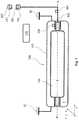
- FIG. 1is a schematic diagram of the basic construction of a cryogenic pressure vessel 100 .
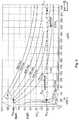
- FIG. 2is a graph of the fluid density D in the inner vessel 110 over the temperature for various inner vessel pressures.
- the cryogenic pressure vessel 100 illustrated in FIG. 1is mounted at its two ends on the vehicle body 50 .
- the outer vessel 120delimits the cryogenic pressure vessel 100 in relation to the environment. Possible additional components of the cryogenic pressure vessel (for example heat exchangers) have been omitted in this simplified illustration.
- the inner vessel 110is arranged in the outer vessel 120 at a distance from the outer vessel 120 .
- the inner vessel 110 illustrated herecomprises domes at its two ends.
- a substantially evacuated or super-insulated space Vis located between the inner vessel 110 and the outer vessel 120 .
- the inner vessel 110is connected via a suspension system at its domes to the outer vessel 120 .
- a supply line 300is connected to the inner vessel 110 .
- the inner vessel 110is refueled through the supply line 300 .
- the sensor 130can measure the pressure and/or the temperature of the evacuated space V.
- connection 150is provided at the other end of the supply line 300 .
- the connection or filler neck 150is designed to be coupled to a corresponding connection 200 of a refueling device.
- a communication interface 160is arranged here in the connection 150 .
- the communication interfaceis able to be connected to a corresponding communication interface 210 in the connection 200 .
- a refueling termination signal and/or a refueling limiting signalcan be transmitted to the refueling device 200 via the communication interface 160 / 210 .
- a radio-based communicationis likewise contemplated (for example WiFi, WLAN, NFC, etc.) which does not have to be accommodated in the connection 200 .
- the refueling valve 180is designed here to interrupt the fluid flow, here a hydrogen flow.
- the refueling valve 180can be arranged anywhere in the supply line 300 .
- the controller 140is designed to control the refueling and the operation of the cryogenic pressure vessel.
- FIG. 2shows the fluid density D in the inner vessel 110 for various inner vessel pressures over the temperature.
- a cryogenic pressure vessel 100 with intact thermal insulation Vis cryogenically refueled, hydrogen is filled into the inner vessel 110 up to an upper fluid density limit value D OB .
- an inner vessel 110which is designed for a maximum vessel inner pressure of approx. 250 to approx. 350 bar (also called maximally permissible inner vessel pressure Pmax or design pressure) can be refueled cryogenically at a temperature TKB of approx. 40 K up to an upper fluid density limit value D OB of approx. 80 gram/liter (point P′KB in FIG. 2 ).
- Pmaxmaximally permissible inner vessel pressure
- the pressure vessel 100has to comparatively rapidly dissipate comparatively large quantities of hydrogen so that the inner vessel 110 is not destroyed by the expanding hydrogen.
- such a great amount of hydrogentherefore then always has to be released starting from the point P′KB that the inner vessel 110 does not have a pressure above the design pressure of approx. 250 to 350 bar at any temperature T.
- the inner vessel 110 of the pressure vessel 100can store, for example, a density of approx. 21 gram/liter in the inner vessel 110 (point PUV in FIG. 2 for a tank with a design pressure of approx. 350 bar). Consequently, the quantity of hydrogen which arises from the product of approx.
- the fluid density Dshould be limited to a lower fluid density limit value D UB for the fluid in the inner vessel 110 , wherein the lower fluid density limit value D UB is selected in such a manner that the inner vessel 110 in the uninsulated state can store the fluid without the maximally permissible inner vessel pressure Pmax being exceeded.
- a lower fluid density limit value DUB of approx. 21 gram/literarises for hydrogen as the fuel. If refueling is permitted for hot use, the vehicle can continue to be used without danger—albeit with a reduced range—without hydrogen being inefficiently consumed in the process. If fiber-reinforced inner vessels are used, for example with braided and/or wound fiber layers around the inner vessel, ranges of more than 200 km can be achieved. Considerable distances can therefore be covered even with damaged thermal insulation. The vehicle driver himself can still bring the vehicle to the service garage and the vehicle does not break down out on the road.
Landscapes
- Engineering & Computer Science (AREA)
- Mechanical Engineering (AREA)
- General Engineering & Computer Science (AREA)
- Filling Or Discharging Of Gas Storage Vessels (AREA)
Abstract
Description
- determining damage to thermal insulation V which is arranged at least in regions between an inner vessel and an outer vessel of the cryogenic pressure vessel; and
- interrupting the refueling of the motor vehicle if, in the event of damaged thermal insulation V, a lower fluid density limit value DUBfor the fluid in the inner vessel is exceeded, wherein the lower fluid density limit value DUBis lower than an upper fluid density limit value DOBfor the fluid in the inner vessel in the case of refueling of the inner vessel with intact thermal insulation V.
Claims (7)
Applications Claiming Priority (4)
| Application Number | Priority Date | Filing Date | Title |
|---|---|---|---|
| DE102014226545.2ADE102014226545A1 (en) | 2014-12-19 | 2014-12-19 | Motor vehicle with a cryogenic pressure vessel and method for refueling a cryogenic pressure vessel of a motor vehicle |
| DE102014226545 | 2014-12-19 | ||
| DE102014226545.2 | 2014-12-19 | ||
| PCT/EP2015/078812WO2016096500A1 (en) | 2014-12-19 | 2015-12-07 | Motor vehicle with a cryogenic pressure vessel and method for refuelling a cryogenic pressure vessel of a motor vehicle |
Related Parent Applications (1)
| Application Number | Title | Priority Date | Filing Date |
|---|---|---|---|
| PCT/EP2015/078812ContinuationWO2016096500A1 (en) | 2014-12-19 | 2015-12-07 | Motor vehicle with a cryogenic pressure vessel and method for refuelling a cryogenic pressure vessel of a motor vehicle |
Publications (2)
| Publication Number | Publication Date |
|---|---|
| US20170225939A1 US20170225939A1 (en) | 2017-08-10 |
| US10655785B2true US10655785B2 (en) | 2020-05-19 |
Family
ID=54848541
Family Applications (1)
| Application Number | Title | Priority Date | Filing Date |
|---|---|---|---|
| US15/496,165Active2036-10-02US10655785B2 (en) | 2014-12-19 | 2017-04-25 | Motor vehicle with a cryogenic pressure vessel and method for refuelling a cryogenic pressure vessel of a motor vehicle |
Country Status (4)
| Country | Link |
|---|---|
| US (1) | US10655785B2 (en) |
| CN (1) | CN106795997B (en) |
| DE (1) | DE102014226545A1 (en) |
| WO (1) | WO2016096500A1 (en) |
Families Citing this family (6)
| Publication number | Priority date | Publication date | Assignee | Title |
|---|---|---|---|---|
| DE102013220388A1 (en)* | 2013-10-09 | 2015-04-09 | Bayerische Motoren Werke Aktiengesellschaft | Safety device of a compressed gas tank in particular of a motor vehicle |
| DE102015206823A1 (en) | 2015-04-15 | 2016-10-20 | Bayerische Motoren Werke Aktiengesellschaft | Method for operating a motor vehicle with a cryogenic pressure vessel |
| DE102015206782A1 (en) | 2015-04-15 | 2016-10-20 | Bayerische Motoren Werke Aktiengesellschaft | Method for refueling a cryogenic pressure vessel of a motor vehicle |
| DE102016216551A1 (en)* | 2016-09-01 | 2018-03-01 | Bayerische Motoren Werke Aktiengesellschaft | Method for determining the insulation quality of a pressure vessel for storing a fuel, in particular hydrogen, in a vehicle and pressure vessel system for a vehicle, comprising a pressure vessel for storing a fuel, in particular hydrogen |
| DE102017209352A1 (en)* | 2017-06-01 | 2018-12-06 | Bayerische Motoren Werke Aktiengesellschaft | Means of transport and method of use of a gas station for receiving gaseous traction energy carriers |
| DE102019126878A1 (en) | 2019-10-07 | 2021-04-08 | Bayerische Motoren Werke Aktiengesellschaft | Method for refueling a motor vehicle, motor vehicle, gas station and computer-readable storage medium |
Citations (15)
| Publication number | Priority date | Publication date | Assignee | Title |
|---|---|---|---|---|
| US4263945A (en)* | 1979-06-20 | 1981-04-28 | Ness Bradford O Van | Automatic fuel dispensing control system |
| EP1205704A1 (en) | 2000-11-08 | 2002-05-15 | GreenField AG | Process for filling a vehicle tank with gas |
| DE102004010937A1 (en) | 2004-03-05 | 2005-09-22 | Airbus Deutschland Gmbh | Cartridge for coupling to a liquid hydrogen user or filling station, and especially for an aircraft, has a tank with an insulated inner lining to hold the liquid or partially-liquid hydrogen and a release connection coupling |
| EP1546601B1 (en) | 2002-09-27 | 2007-08-08 | The Regents Of the University of California | Lightweight cryogenic-compatible pressure vessels for vehicular fuel storage |
| WO2008145584A1 (en) | 2007-05-31 | 2008-12-04 | Airbus Operations Gmbh | Device and method for storing hydrogen for an aircraft |
| DE102008019594A1 (en) | 2008-04-18 | 2009-10-22 | Bayerische Motoren Werke Aktiengesellschaft | Heat-insulated container for condensed gases |
| WO2011061584A1 (en) | 2009-11-18 | 2011-05-26 | Toyota Jidosha Kabushiki Kaisha | Gas filling system, gas filling method, and vehicle |
| US20120125482A1 (en) | 2009-07-30 | 2012-05-24 | Toyota Jidosha Kabushiki Kaisha | Gas filling system |
| US20120205003A1 (en) | 2009-10-19 | 2012-08-16 | Toyota Jidosha Kabushiki Kaisha | Gas filling device, gas filling system, gas filling method and moving device |
| US20120216910A1 (en) | 2009-11-16 | 2012-08-30 | Shusuke Inagi | Gas charging apparatus and gas charging method |
| DE112010005175T5 (en) | 2010-01-25 | 2012-10-31 | Murata Manufacturing Co., Ltd. | Electronic module and communication device |
| US20120318378A1 (en) | 2010-02-15 | 2012-12-20 | Hiroki Yahashi | Vehicle |
| US20130014854A1 (en) | 2010-01-25 | 2013-01-17 | Tomoyuki Mori | Fuel gas station, fuel gas filling system, and fuel gas supplying method |
| DE102012218989A1 (en) | 2012-10-18 | 2014-06-12 | Bayerische Motoren Werke Aktiengesellschaft | Arrangement of a sensor system on a vacuum-insulated container system, in particular on a cryotank |
| US20150028039A1 (en)* | 2012-03-26 | 2015-01-29 | Bayerische Motoren Werke Aktiengesellschaft | Vehicle Tank System for Storing a Fuel in an Extremely Cold State |
Family Cites Families (1)
| Publication number | Priority date | Publication date | Assignee | Title |
|---|---|---|---|---|
| CN203099305U (en)* | 2012-12-27 | 2013-07-31 | 诸城市良丰容器设备有限公司 | Marine horizontal-type liquefied natural gas storage tank |
- 2014
- 2014-12-19DEDE102014226545.2Apatent/DE102014226545A1/enactivePending
- 2015
- 2015-12-07CNCN201580054841.3Apatent/CN106795997B/enactiveActive
- 2015-12-07WOPCT/EP2015/078812patent/WO2016096500A1/enactiveApplication Filing
- 2017
- 2017-04-25USUS15/496,165patent/US10655785B2/enactiveActive
Patent Citations (21)
| Publication number | Priority date | Publication date | Assignee | Title |
|---|---|---|---|---|
| US4263945A (en)* | 1979-06-20 | 1981-04-28 | Ness Bradford O Van | Automatic fuel dispensing control system |
| EP1205704A1 (en) | 2000-11-08 | 2002-05-15 | GreenField AG | Process for filling a vehicle tank with gas |
| EP1546601B1 (en) | 2002-09-27 | 2007-08-08 | The Regents Of the University of California | Lightweight cryogenic-compatible pressure vessels for vehicular fuel storage |
| DE102004010937A1 (en) | 2004-03-05 | 2005-09-22 | Airbus Deutschland Gmbh | Cartridge for coupling to a liquid hydrogen user or filling station, and especially for an aircraft, has a tank with an insulated inner lining to hold the liquid or partially-liquid hydrogen and a release connection coupling |
| WO2008145584A1 (en) | 2007-05-31 | 2008-12-04 | Airbus Operations Gmbh | Device and method for storing hydrogen for an aircraft |
| DE102008019594A1 (en) | 2008-04-18 | 2009-10-22 | Bayerische Motoren Werke Aktiengesellschaft | Heat-insulated container for condensed gases |
| US20120125482A1 (en) | 2009-07-30 | 2012-05-24 | Toyota Jidosha Kabushiki Kaisha | Gas filling system |
| DE112010003119T5 (en) | 2009-07-30 | 2013-03-14 | Toyota Jidosha K.K. | gas filling |
| DE112009005421T5 (en) | 2009-10-19 | 2012-12-06 | Toyota Jidosha Kabushiki Kaisha | Gas filling device, gas filling system, gas filling method and movement device |
| US20120205003A1 (en) | 2009-10-19 | 2012-08-16 | Toyota Jidosha Kabushiki Kaisha | Gas filling device, gas filling system, gas filling method and moving device |
| DE112010004411T5 (en) | 2009-11-16 | 2013-04-18 | Toyota Jidosha Kabushiki Kaisha | Gas filling device and gas filling method |
| US20120216910A1 (en) | 2009-11-16 | 2012-08-30 | Shusuke Inagi | Gas charging apparatus and gas charging method |
| DE112010004462T5 (en) | 2009-11-18 | 2012-08-30 | Toyota Jidosha Kabushiki Kaisha | GAS FILLING SYSTEM, GAS FILLING PROCEDURE AND VEHICLE |
| US20120227864A1 (en) | 2009-11-18 | 2012-09-13 | Tomoyuki Mori | Gas filling system, gas filling method, and vehicle |
| WO2011061584A1 (en) | 2009-11-18 | 2011-05-26 | Toyota Jidosha Kabushiki Kaisha | Gas filling system, gas filling method, and vehicle |
| DE112010005175T5 (en) | 2010-01-25 | 2012-10-31 | Murata Manufacturing Co., Ltd. | Electronic module and communication device |
| US20130014854A1 (en) | 2010-01-25 | 2013-01-17 | Tomoyuki Mori | Fuel gas station, fuel gas filling system, and fuel gas supplying method |
| US20120318378A1 (en) | 2010-02-15 | 2012-12-20 | Hiroki Yahashi | Vehicle |
| DE112011100541B4 (en) | 2010-02-15 | 2014-06-05 | Toyota Jidosha Kabushiki Kaisha | vehicle |
| US20150028039A1 (en)* | 2012-03-26 | 2015-01-29 | Bayerische Motoren Werke Aktiengesellschaft | Vehicle Tank System for Storing a Fuel in an Extremely Cold State |
| DE102012218989A1 (en) | 2012-10-18 | 2014-06-12 | Bayerische Motoren Werke Aktiengesellschaft | Arrangement of a sensor system on a vacuum-insulated container system, in particular on a cryotank |
Non-Patent Citations (6)
| Title |
|---|
| Cover page of EP 2 162 670 A0 published Mar. 17, 2010 (one (1) page). |
| Gas constant, Wikipedia, the free encyclopedia, URL: https://de.wikipedia.org/w/index.php?title=Gaskonstante&oldid=135596974 retrieved Apr. 18, 2017, with English translation (Eight (8) pages). |
| German-language Search Report issued in counterpart German Application No. 10 2014 226 545.2 dated Nov. 6, 2015 with partial English translation (Fifteen (15) pages). |
| German-language Written Opinion (PCT/ISA/237) issued in PCT Application No. PCT/EP2015/078812 dated Apr. 5, 2016 (Seven (7) pages). |
| Ideal gas law, Wikipedia, the free encyclopedia, URL: https://de.wikipedia.org/w/index.php?title=Thermische_Zustandsgleichung_idealer_Gase&oldid=135596608 retrieved Apr. 18, 2017, With English translation (Fourteen (14) pages). |
| International Search Report (PCT/ISA/210) issued in PCT Application No. PCT/EP2015/078812 dated Apr. 5, 2016 with English translation (Four (4) pages). |
Also Published As
| Publication number | Publication date |
|---|---|
| US20170225939A1 (en) | 2017-08-10 |
| WO2016096500A1 (en) | 2016-06-23 |
| CN106795997A (en) | 2017-05-31 |
| CN106795997B (en) | 2019-07-05 |
| DE102014226545A1 (en) | 2016-06-23 |
Similar Documents
| Publication | Publication Date | Title |
|---|---|---|
| US10655785B2 (en) | Motor vehicle with a cryogenic pressure vessel and method for refuelling a cryogenic pressure vessel of a motor vehicle | |
| US9163616B2 (en) | Passive closing device for thermal self-protection of high pressure gas vessels | |
| CA3092331C (en) | Mobile hydrogen dispenser for fuel cell vehicles | |
| US8408247B2 (en) | Element for controlling filling and/or drawing of a pressurized gas, tank and circuit provided with such an element | |
| CN111295547B (en) | Safety valve for pressure vessel and pressure vessel system with trigger line | |
| JP5327382B2 (en) | Hydrogen filling system | |
| US11415084B2 (en) | Storage tank for cryogenic liquid gas | |
| CN110621928B (en) | Pressure relief device with variable mass flow | |
| US9903535B2 (en) | Cryogenic liquid conditioning and delivery system | |
| US20110041307A1 (en) | Replaceable cartridge for liquid hydrogen | |
| JP2013117301A (en) | Hydrogen safe filling system and hydrogen safe filling method | |
| CN102913674B (en) | Hot pressure relief device | |
| JP2010520977A (en) | Method for filling hydrogen storage container | |
| KR20220085830A (en) | leak detection | |
| KR20180087397A (en) | A method and system for determining time data relating to a non-combustion exhaust process of a fuel gas from a gas tank of a vehicle | |
| CN111902307A (en) | Motor vehicle having a thermally activatable pressure relief device and method for relieving pressure | |
| US20190003648A1 (en) | Method for Cooling a First Cryogenic Pressure Vessel | |
| KR20190054846A (en) | Double wall pressure vessel | |
| JP2006316817A (en) | Hydrogen supply method, hydrogen supply device | |
| CN114466989B (en) | Method for refueling a motor vehicle, motor vehicle, refueling station and computer readable storage medium | |
| CN211289555U (en) | Environment-friendly energy-saving liquefied natural gas cylinder | |
| KR100962896B1 (en) | Hydrogen Safety Filling Methods for Hydrogen Storage Systems | |
| US5511383A (en) | Method and apparatus for maintaining the level of cold liquid within a vessel | |
| US20250027612A1 (en) | Active venting control system for hydrogen fuel tanks | |
| JP7681607B2 (en) | Valve for pressurized fluid reservoir |
Legal Events
| Date | Code | Title | Description |
|---|---|---|---|
| AS | Assignment | Owner name:BAYERISCHE MOTOREN WERKE AKTIENGESELLSCHAFT, GERMANY Free format text:ASSIGNMENT OF ASSIGNORS INTEREST;ASSIGNOR:KUNBERGER, JAN-MARK;REEL/FRAME:042135/0564 Effective date:20170310 Owner name:BAYERISCHE MOTOREN WERKE AKTIENGESELLSCHAFT, GERMA Free format text:ASSIGNMENT OF ASSIGNORS INTEREST;ASSIGNOR:KUNBERGER, JAN-MARK;REEL/FRAME:042135/0564 Effective date:20170310 | |
| STPP | Information on status: patent application and granting procedure in general | Free format text:NON FINAL ACTION MAILED | |
| STPP | Information on status: patent application and granting procedure in general | Free format text:RESPONSE TO NON-FINAL OFFICE ACTION ENTERED AND FORWARDED TO EXAMINER | |
| STPP | Information on status: patent application and granting procedure in general | Free format text:NOTICE OF ALLOWANCE MAILED -- APPLICATION RECEIVED IN OFFICE OF PUBLICATIONS | |
| STPP | Information on status: patent application and granting procedure in general | Free format text:PUBLICATIONS -- ISSUE FEE PAYMENT VERIFIED | |
| STCF | Information on status: patent grant | Free format text:PATENTED CASE | |
| MAFP | Maintenance fee payment | Free format text:PAYMENT OF MAINTENANCE FEE, 4TH YEAR, LARGE ENTITY (ORIGINAL EVENT CODE: M1551); ENTITY STATUS OF PATENT OWNER: LARGE ENTITY Year of fee payment:4 |