US10654486B2 - Sensor systems integrated with steering wheels - Google Patents
Sensor systems integrated with steering wheelsDownload PDFInfo
- Publication number
- US10654486B2 US10654486B2US15/690,108US201715690108AUS10654486B2US 10654486 B2US10654486 B2US 10654486B2US 201715690108 AUS201715690108 AUS 201715690108AUS 10654486 B2US10654486 B2US 10654486B2
- Authority
- US
- United States
- Prior art keywords
- sensor
- sensors
- circuitry
- calibration data
- force
- Prior art date
- Legal status (The legal status is an assumption and is not a legal conclusion. Google has not performed a legal analysis and makes no representation as to the accuracy of the status listed.)
- Expired - Fee Related, expires
Links
Images


Classifications
- B—PERFORMING OPERATIONS; TRANSPORTING
- B60—VEHICLES IN GENERAL
- B60W—CONJOINT CONTROL OF VEHICLE SUB-UNITS OF DIFFERENT TYPE OR DIFFERENT FUNCTION; CONTROL SYSTEMS SPECIALLY ADAPTED FOR HYBRID VEHICLES; ROAD VEHICLE DRIVE CONTROL SYSTEMS FOR PURPOSES NOT RELATED TO THE CONTROL OF A PARTICULAR SUB-UNIT
- B60W50/00—Details of control systems for road vehicle drive control not related to the control of a particular sub-unit, e.g. process diagnostic or vehicle driver interfaces
- B60W50/0098—Details of control systems ensuring comfort, safety or stability not otherwise provided for
- B—PERFORMING OPERATIONS; TRANSPORTING
- B60—VEHICLES IN GENERAL
- B60W—CONJOINT CONTROL OF VEHICLE SUB-UNITS OF DIFFERENT TYPE OR DIFFERENT FUNCTION; CONTROL SYSTEMS SPECIALLY ADAPTED FOR HYBRID VEHICLES; ROAD VEHICLE DRIVE CONTROL SYSTEMS FOR PURPOSES NOT RELATED TO THE CONTROL OF A PARTICULAR SUB-UNIT
- B60W40/00—Estimation or calculation of non-directly measurable driving parameters for road vehicle drive control systems not related to the control of a particular sub unit, e.g. by using mathematical models
- B60W40/08—Estimation or calculation of non-directly measurable driving parameters for road vehicle drive control systems not related to the control of a particular sub unit, e.g. by using mathematical models related to drivers or passengers
- B60W40/09—Driving style or behaviour
- B—PERFORMING OPERATIONS; TRANSPORTING
- B62—LAND VEHICLES FOR TRAVELLING OTHERWISE THAN ON RAILS
- B62D—MOTOR VEHICLES; TRAILERS
- B62D1/00—Steering controls, i.e. means for initiating a change of direction of the vehicle
- B62D1/02—Steering controls, i.e. means for initiating a change of direction of the vehicle vehicle-mounted
- B62D1/04—Hand wheels
- B62D1/046—Adaptations on rotatable parts of the steering wheel for accommodation of switches
- B—PERFORMING OPERATIONS; TRANSPORTING
- B62—LAND VEHICLES FOR TRAVELLING OTHERWISE THAN ON RAILS
- B62D—MOTOR VEHICLES; TRAILERS
- B62D1/00—Steering controls, i.e. means for initiating a change of direction of the vehicle
- B62D1/02—Steering controls, i.e. means for initiating a change of direction of the vehicle vehicle-mounted
- B62D1/04—Hand wheels
- B62D1/06—Rims, e.g. with heating means; Rim covers
- G—PHYSICS
- G01—MEASURING; TESTING
- G01L—MEASURING FORCE, STRESS, TORQUE, WORK, MECHANICAL POWER, MECHANICAL EFFICIENCY, OR FLUID PRESSURE
- G01L1/00—Measuring force or stress, in general
- G01L1/18—Measuring force or stress, in general using properties of piezo-resistive materials, i.e. materials of which the ohmic resistance varies according to changes in magnitude or direction of force applied to the material
Definitions
- a sensor systemincludes a flexible dielectric substrate, flexible piezoresistive material in contact with the flexible dielectric substrate, and an array of sensors.
- Each sensorincludes at least two conductive traces formed on the flexible dielectric substrate such that each sensor is also in contact with a portion of the flexible piezoresistive material.
- Sensor circuitryis configured to selectively energize the sensors, and to receive sensor signals from the array of sensors. Each sensor signal represents a force associated with a corresponding one of the sensors.
- the flexible dielectric substrate, the piezoresistive material, and the array of sensorsare configured for wrapping around the steering wheel such that the array of sensors conforms to a portion of a circumference of the steering wheel.
- a sensor systemincludes a flexible piezoresistive substrate, and an array of sensors.
- Each sensorincludes at least two conductive traces formed on the flexible piezoresistive substrate.
- Sensor circuitryis configured to selectively energize the sensors, and to receive sensor signals from the array of sensors.
- Each sensor signalrepresents a force associated with a corresponding one of the sensors.
- the flexible piezoresistive substrate and the array of sensorsare configured for wrapping around the steering wheel such that the array of sensors conforms to a portion of a circumference of the steering wheel.
- the sensor circuitryis configured to adjust each of the sensor signals with calibration data for the corresponding sensor, thereby substantially normalizing force data derived from the sensor signals.
- the sensor circuitryis configured to repeatedly recalculate the calibration data for each of the sensors after the sensor system is integrated with the steering wheel.
- the sensor circuitryis configured to detect a grip event associated with consecutively arranged sensors of the sensor array by determining that a force associated with each of the consecutively arranged sensors exceeds a threshold for a specified duration.
- the sensor circuitryis configured to detect a swipe event associated with consecutively arranged sensors of the sensor array by determining that a positive change in force associated with each of the consecutively arranged sensors exceeds a first threshold for a first specified duration, and a negative change in force associated with each of the consecutively arranged sensors exceeds a second threshold for a second specified duration.
- a sensor systemincludes an array of sensors configured for integration with the steering wheel such that the array of sensors conforms to a portion of a circumference of the steering wheel.
- Sensor circuitryis configured to selectively energize the sensors, and to receive sensor signals from the array of sensors. Each sensor signal represents a force associated with a corresponding one of the sensors.
- the sensor circuitryis configured to adjust each of the sensor signals with calibration data for the corresponding sensor, thereby substantially normalizing force data derived from the sensor signals.
- the sensor circuitryis also configured to recalculate the calibration data for each of the sensors after the sensor system is integrated with the steering wheel.
- a sensor systemincludes an array of sensors configured for integration with the steering wheel such that the array of sensors conforms to a portion of a circumference of the steering wheel.
- Sensor circuitryis configured to receive sensor signals from the array of sensors. Each sensor signal represents a force associated with a corresponding one of the sensors.
- the sensor circuitryis configured to detect a grip event associated with first consecutively arranged sensors of the sensor array by determining that a force associated with each of the first consecutively arranged sensors exceeds a first threshold for a first specified duration.
- the first sensor circuitryis also configured to detect a swipe event associated with second consecutively arranged sensors of the sensor array by determining that a positive change in force associated with each of the second consecutively arranged sensors exceeds a second threshold for a second specified duration, and a negative change in force associated with each of the second consecutively arranged sensors exceeds a third threshold for a third specified duration.
- FIG. 1shows a particular implementation of steering wheel sensor system.
- FIG. 2is a simplified block diagram of sensor circuitry suitable for use with various implementations.
- FIG. 3illustrates integration of a sensor system with a steering wheel according to a particular implementation.
- FIG. 4shows part of a steering wheel sensor system according to a particular implementation.
- FIG. 5provides visual representations of data generated by a steering wheel sensor system according to a particular implementation.
- FIG. 6illustrates integration of a sensor system with a steering wheel according to another implementation.
- FIG. 7shows a cross-sectional view of the layers of a steering wheel sensor system according to a particular implementation.
- FIG. 8shows an exploded view of the layers of a steering wheel sensor system according to a particular implementation.
- FIGS. 9 and 10are flowcharts illustrating aspects of the operation of a steering wheel sensor system according to particular implementations.
- Piezoresistive materialsinclude any of a class of materials that exhibit a change in electrical resistance in response to mechanical force (e.g., pressure, impact, distortion, etc.) applied to the material.
- One class of sensors described hereinincludes conductive traces formed directly on or otherwise integrated with a flexible substrate of piezoresistive material, e.g., a piezoresistive fabric or other flexible material.
- Another class of sensors described hereinincludes conductive traces formed directly on or otherwise integrated with a flexible dielectric substrate with flexible piezoresistive material that is adjacent and/or tightly integrated with the dielectric substrate and in contact with (or in some cases held slightly off of) portions of the traces. When force is applied to such a sensor, the resistance between traces connected by the piezoresistive material changes in a time-varying manner that is representative of the applied force.
- a signal representative of the magnitude of the applied forceis generated based on the change in resistance.
- This signalis captured via the conductive traces (e.g., as a voltage or a current), digitized (e.g., via an analog-to-digital converter), processed (e.g., by an associated processor, controller, or suitable control circuitry), and potentially mapped (e.g., by the associated processor, controller, or control circuitry) to a control function that may be used in conjunction with virtually any type of process, device, or system.
- the output signals from such sensorsmay also be used to detect a variety of distortions and/or deformations of the substrate(s) on which they are formed or with which they are integrated such as, for example, bends, stretches, torsions, rotations, etc.
- arrays of sensors having various configurationsare described in this disclosure.
- the piezoresistive material on which the traces are formed or with which the traces are in contactmay be any of a variety of woven and non-woven fabrics having piezoresistive properties. Implementations are also contemplated in which the piezoresistive material may be any of a variety of flexible, stretchable, or otherwise deformable materials (e.g., rubber, or a stretchable fabric such as spandex or open mesh fabrics) having piezoresistive properties.
- the conductive tracesmay be formed on the piezoresistive material or a flexible dielectric substrate using any of a variety of conductive inks or paints. More generally, implementations are contemplated in which the conductive traces are formed using any flexible conductive material that may be formed on a flexible substrate. It should be understood with reference to the foregoing that, while specific implementations are described with reference to specific materials and techniques, the scope of this disclosure is not so limited.
- conductive tracescan be printed or formed on one or both sides of a flexible substrate.
- two-sided implementationsmay require some mechanism for connecting conductive traces on one side of the substrate to those on the other side.
- Some implementationsuse vias in which conductive ink or paint is flowed through the vias to establish the connections.
- conductive vias or rivetsmay make connections through the flexible substrate.
- Both single and double-sided implementationsmay also use insulating materials formed over or under conductive traces. This allows for the stacking or layering of conductive traces and signal lines, e.g., to allow the routing of signal line to isolated structures in a manner analogous to the different layers of a printed circuit board.
- Routing of signals on and off the flexible substratemay be achieved in a variety of ways.
- elastomeric connectorse.g., ZEBRA® connectors
- ZEBRA® connectorswhich alternate conductive and non-conductive rubber at a density typically an order of magnitude greater than the width of the conductive traces to which they connect (e.g., at the edge of the substrate).
- a circuit boardpossibly made of a flexible material such as Kapton
- a bundle of conductorsmay be riveted or otherwise secured to the substrate. The use of rivets may also provide mechanical reinforcement to the connection.
- matching conductive traces or pads on the flexible substrate and a circuit boardcan be secured to each other using, for example, a layer of conductive adhesive (e.g., a conductive epoxy such as Masterbond EP79 from Masterbond, Inc. of Hackensack, N.J.) applied to one or both of the surfaces which are then mated to each other.
- the conductive traces or padscan also be held together with additional mechanical elements such as sonic welds or rivets. If conductive rivets are used to make the electrical connections to the conductive traces of the flexible substrate, the conductive adhesive may not be required.
- Conductive threadsmay also be used to connect the conductive traces of the flexible substrate to an external assembly.
- the piezoresistive materialis a pressure sensitive fabric manufactured by Eeonyx, Inc., of Pinole, Calif.
- the fabricincludes conductive particles that are polymerized to keep them suspended in the fabric.
- the base materialis a polyester felt selected for uniformity in density and thickness as this promotes greater uniformity in conductivity of the finished piezoresistive fabric. That is, the mechanical uniformity of the base material results in a more even distribution of conductive particles when the slurry containing the conductive particles is introduced.
- the fabricmay be woven.
- the fabricmay be non-woven such as, for example, a calendared fabric, e.g., fibers bonded together by chemical, mechanical, heat, or solvent treatment.
- calendared materialmay present a smooth outer surface which promotes more accurate screening of conductive inks.
- the conductive particles in the fabricmay be any of a wide variety of materials including, for example, silver, copper, gold, aluminum, carbon, etc. Some implementations may employ carbon graphenes that are formed to grip the fabric. Such materials may be fabricated using techniques described in U.S. Pat. No. 7,468,332 for Electroconductive Woven and Non-Woven Fabric issued on Dec. 23, 2008, the entire disclosure of which is incorporated herein by reference for all purposes. However, it should again be noted that any of a wide variety of flexible materials that exhibit a change in resistance or conductivity when force is applied to the material may be suitable for implementation of sensors as described herein.
- conductive traces having varying levels of conductivityare formed on flexible piezoresistive material or a flexible dielectric substrate using conductive silicone-based inks manufactured by, for example, E.I. du Pont de Nemours and Company (DuPont) of Wilmington, Del., and/or Creative Materials of Ayer, Mass.
- conductive silicone-based inksmanufactured by, for example, E.I. du Pont de Nemours and Company (DuPont) of Wilmington, Del., and/or Creative Materials of Ayer, Mass.
- An example of a conductive ink suitable for implementing highly conductive traces for use with various implementationsis product number 125-19 from Creative Materials, a flexible, high temperature, electrically conductive ink.
- Examples of conductive inks for implementing lower conductivity traces for use with various implementationsare product numbers 7102 and 7105 from DuPont, both carbon conductive compositions.
- dielectric materials suitable for implementing insulators for use with various implementationsare product numbers 5018 and 5036 from DuPont, a UV curable dielectric and an encapsulant, respectively. These inks are flexible and durable and can handle creasing, washing, etc. The degree of conductivity for different traces and applications is controlled by the amount or concentration of conductive particles (e.g., silver, copper, aluminum, carbon, etc.) suspended in the silicone. These inks can be screen printed or printed from an inkjet printer. Another class of implementations uses conductive paints (e.g., carbon particles mixed with paint) such as those that are commonly used for EMI shielding and ESD protection.
- conductive paintse.g., carbon particles mixed with paint
- a steering wheel sensor systemin which a sensor array is attached to or integrated with a steering wheel and is configured to provide information regarding forces exerted on the steering wheel, e.g., by the hands of a driver.
- FIG. 1is an illustration of an example of such a sensor system.
- the depicted steering wheel sensor systemincludes fifteen sensors that capture data at locations around a steering wheel to which it is attached or with which it is integrated.
- the strip of material with which the sensors are integratedis wrapped around at least a portion of the torus of the steering wheel.
- the stripruns lengthwise along the circumference of the steering wheel with the width of the strip being wrapped around the steering wheel (e.g., see FIG. 3 ). And depending on the implementation, there may be one or multiple such sensor arrays to capture force information around all or only portions of the steering wheel.
- the sensorsare implemented with conductive trace patterns that are formed directly on or otherwise integrated with a flexible substrate; either a piezoresistive material or a dielectric material.
- portions of the conductive traces that are not intended to be part of a sensore.g., signal routing traces
- the portions of the conductive traces that bring the drive and sense signals to and from the sensorsmay be insulated from the piezoresistive material using, for example, a dielectric or non-conducting material (shaded portion of the array at the bottom of the figure) that is formed on the piezoresistive material before the conductive traces. Portions of the conductive traces are then formed over the insulating material. The insulating material may also be formed over the conductive traces to allow traces to cross or be routed in the same area.
- each of the sensorsincludes two adjacent traces, the respective patterns of which each include extensions that alternate or are “interdigitated” with the extensions of the other. See, for example, the magnified view of sensor S 6 .
- trace patterns 108 - 116are some representative examples.
- One of the traces 101receives a drive signal; the other trace 102 transmits the corresponding sensor signal to associated sensor circuitry (e.g., on PCB 122 ).
- the drive signalmight be provided, for example, by connecting the trace (permanently or temporarily) to a voltage reference, a signal source that may include additional information in the drive signal, a GPIO (General Purpose Input Output) pin of an associated processor or controller, etc.
- a GPIOGeneral Purpose Input Output
- the sensor signalmight be generated using a voltage divider in which one of the resistors of the divider includes the resistance between the two traces of the sensor through the intervening piezoresistive material.
- the other resistorrepresented by R 1
- the sensor signalalso varies as a divided portion of the drive signal.
- any of a wide variety of transformations of the drive signal via the change in resistance of the piezoresistive materialmay be employed for particular applications.
- the sensorsare energized (via the drive signals) and interrogated (via the sensor signals) to generate an output signal for each that is a representation of the amount of force exerted on or near that sensor.
- the sensorsare energized (via the drive signals) and interrogated (via the sensor signals) to generate an output signal for each that is a representation of the amount of force exerted on or near that sensor.
- implementationsare contemplated having more or fewer sensors.
- different sets of sensorsmay be selectively energized and interrogated thereby reducing the number and overall area of traces on the substrate, as well as the required connections to sensor circuitry on an associated PCB (e.g., PCB 122 ).
- PCBe.g., PCB 122
- the 15 sensorsare driven sequentially so that they can share the same sensor signal line.
- the sensor system of FIG. 1could include additional sensors with the same number of connections to PCB 122 .
- 28 sensorsmight be driven via 14 drive signal outputs from the sensor circuitry (not shown) on PCB 122 , and the sensor signals could be received via 2 sensor signal inputs (rather than 1) to the sensor circuitry on PCB 122 ; with the same number of connections between the substrate and the PCB (i.e., 16 in the depicted example).
- the set of sensors providing sensor signals to one of the 2 sensor signal inputsmay be energized in any suitable sequence or pattern such that any signal received on the corresponding sensor signal input can be correlated with the corresponding sensor drive signal by the sensor circuitry.
- PCB 122may be connected to the conductive traces of the sensor array as described U.S. Patent Publication No. 2015/0331533 entitled Flexible Sensors and Applications filed on Mar. 27, 2015, the entire disclosure of which is incorporated herein by reference for all purposes.
- any of a variety of techniquesmay be employed to make such a connection including, for example, elastomeric connectors (e.g., ZEBRA® connectors) which alternate conductive and non-conductive rubber at a density typically an order of magnitude greater than the width of the conductive traces to which they connect (e.g., at the edge of the fabric).
- elastomeric connectorse.g., ZEBRA® connectors
- ZEBRA® connectorsalternate conductive and non-conductive rubber at a density typically an order of magnitude greater than the width of the conductive traces to which they connect (e.g., at the edge of the fabric).
- a variety of other suitable alternativesare available to those of skill in the art.
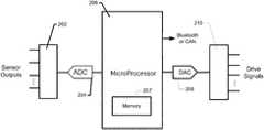
- FIG. 2is a simplified diagram of sensor circuitry that may be provided on a PCB for use with implementations described herein.
- sensor circuitrycould be provided on PCB 122 and connected to the conductive traces associated with sensors S 1 -S 15 .
- a resulting signal(captured via the corresponding traces) is received and digitized (e.g., via multiplexer 202 and A-to-D converter 204 ) and may be processed locally (e.g., by processor 206 ) and/or transmitted to a connected device or application (e.g., via a wired or a wireless connection).
- the steering wheel sensor systemmight communicate (wired or wirelessly) over an automotive Controller Area Network (CAN), a local interconnect network (LIN), an Ethernet network, a Bluetooth or other wireless connection, etc., with one or more of a vehicle's onboard computing or control systems.
- CANAutomotive Controller Area Network
- LINlocal interconnect network
- EthernetEthernet
- BluetoothBluetooth or other wireless connection
- the systemmight communicate with an application on, for example, a smart phone or tablet.
- the sensorsmay be selectively energized by the sensor circuitry (e.g., under the control of processor 206 via D-to-A converter 208 and multiplexer 210 ) to effect the generation of the sensor signals.
- the sensor circuitrymay be powered, for example, by the vehicle's electrical system (e.g., via the steering column and/or hub of the steering wheel).
- the sensor circuitrymight have an associated power source such as, for example, a battery, an energy-harvesting power supply (e.g., the LTC3588 provided by Linear Technology Corporation of Milpitas, Calif.), or the like.
- Processor 206may be implemented using any of a wide variety of controllers such as, for example, the C8051F380-GM controller provided by Silicon Labs of Austin, Tex.
- Memory 207includes non-transitory computer-readable storage media that may be any of a wide variety of types of volatile and non-volatile storage media, and may include computer readable instructions, data structures, program modules, logic, firmware, and/or other data that implement or support the functionalities described herein.
- the sensor circuitry of FIG. 2is only one example of how the various functionalities described herein may be implemented.
- processors, controllers, and similar commercially available devicesthat may be employed, other types of devices and circuits may be employed.
- many of the functionalities described hereincould be implemented using application-specific integrated circuits (ASICs), programmable logic devices (PLDs), or field-programmable gate array (FPGA) devices.
- ASICsapplication-specific integrated circuits
- PLDsprogrammable logic devices
- FPGAfield-programmable gate array
- Various combinations of discrete digital and/or analog circuit componentsmay also be used. The scope of the present disclosure should therefore not be limited by the specific examples of sensor circuitry described herein.
- Sensor system 300is shown at the top of the figure in its flattened configuration and then, in the middle of the figure, wrapped around a cylindrical surface. At the bottom of the figure, a portion of sensor system 300 is shown in relation to a section of steering wheel 302 around which it may be wrapped; following the curve of steering wheel 302 .
- One or multiple instances of sensor system 300may be provided around the circumference of steering wheel 302 to provide desired coverage. Any of a variety of materials (e.g., leather or other standard materials) may be wrapped around the sensor system to provide a desired look and feel, protect the sensors from the environment, etc.
- the flexible substrate of the sensor systemmay include relief cutouts (e.g., 104 , 304 ) that allow the substrate to conform to the shape of the steering wheel.
- the sensorsare spaced with their centers approximately an inch apart allowing for sufficient resolution to distinguish, for example, the individual fingers of the driver. More generally, the sensor may be configured to detect multiple contact points substantially simultaneously. For example, the pressure distribution over the fingers of each of the driver's hand could be captured.
- the pressure required to activate a sensormay be configurable as well. According to a specific implementation, the sensor activation threshold is in the range of about 50-100 grams of pressure.
- each individual sensorcan be adjusted in a variety of ways. For example, the distance between and/or the numbers of the interdigitated extensions of the conductive trace patterns may be manipulated. The conductivity of the trace patterns may also be manipulated. Mechanical elements can focus the forces to the area between the interdigitated conductors; effectively providing a “lens” to direct the grip pressure to parts of the sensor that are active. See, for example, mechanical elements described in U.S. Patent Publication No. 2015/0331523 referenced above. Software multipliers can be used on values derived from sensor signals to adjust sensitivity, as well as adjustments to the levels of the drive signals used to energize the sensors.
- sensitivitymay be controlled in response to external conditions such as, for example, temperature and/or humidity which can affect the stiffness of the materials (e.g., leather wrapping) associated with the sensor system.
- the sensorswhen the steering wheel sensor system powers up, the sensors may be calibrated using an “auto zero” process by which each sensor is energized and interrogated with the resulting value being stored by the system as corresponding to zero force.
- auto zeroif the value for one or more of the sensors is disproportionate (particularly for consecutive sensors in the array) this may be treated as if the steering wheel is already being touched. In such a case, previously stored values may be used as the zero-pressure baseline.
- drive signalsmay be routed to the sensors on the piezoresistive substrate and/or sensor signals may be routed from the sensors to the sensor circuitry via an adjacent substrate.
- Such an approachmight be useful, for example, to allow the sensors to occupy more of the width of the piezoresistive substrate than might otherwise be possible.
- contacts for each of the sensorsare formed on the piezoresistive substrate on which the sensors are included. For example, referring to the sensor array shown in FIG. 1 , such a contact might be formed at the bottom right-hand corner of sensor S 6 where the drive signal is applied and/or at the upper left-hand corner where the sensor signal is transmitted. Similar contacts could be formed near each of the other sensors.
- FIG. 4illustrates an implementation of a sensor array similar in some respects to the arrays of FIGS. 1 and 3 , but in which traces routing drive signals from associated sensor circuitry (not shown) to the sensor trace patterns on piezoresistive substrate 402 are provided on a separate substrate 404 . Only portions of substrates 402 and 404 are shown for clarity. In the example depicted, each sensor on substrate 402 has an associated contact 406 which corresponds to a matching contact 408 on substrate 404 .
- FIG. 4provides a cross-sectional view 412 of the resulting vertical stack at a pair of matching contact points with piezoresistive substrate 402 at the bottom, matching contact points 406 and 408 in the middle, and substrate 404 at the top.
- the depicted orientation of the stackis arbitrary and the features are not necessarily drawn to scale.
- Substrate 404also includes conductive traces 414 connected to corresponding ones of contacts 408 that route each of the drive signals from the sensor circuitry to the corresponding sensor via the matching contacts.
- the sensor circuitrycould be on a PCB that is attached to or integrated with the adjacent substrate (e.g., as described in U.S. Patent Publication No. 2015/0331533 referred to above).
- the sensor circuitrycould be on a PCB that is attached to or integrated with the piezoresistive substrate or even another substrate (e.g., as described in Publication No. 2015/0331533) using another set of conductive traces and matching contacts that transmit the drive signals from one substrate to the other.
- additional traces on the same or an additional substratemight also be provided for routing sensor signals from the sensor trace patterns to the sensor circuitry, e.g., via contacts 416 .
- the adjacent substrate on which signals are routedis a thermoplastic polyurethane (TPU) (such as, for example, Products ST604, ET315, or 3918 from Bemis Associates Inc. of Shirley, Mass.) on which the matching contacts and conductive traces are screen printed using a conductive flexible ink such as, for example, conductive silicone-based inks manufactured by E.I. du Pont de Nemours and Company (DuPont) of Wilmington, Del., and/or Creative Materials of Ayer, Mass.
- TPUthermoplastic polyurethane
- a conductive flexible inksuch as, for example, conductive silicone-based inks manufactured by E.I. du Pont de Nemours and Company (DuPont) of Wilmington, Del., and/or Creative Materials of Ayer, Mass.
- insulators and/or dielectricsmay be formed over the traces on the TPU substrate before making the connections to insulate them from the traces on the piezoresistive substrate and from the piezoresistive substrate itself.
- the traces on the TPU substratemay also be formed on the side of the TPU substrate opposite the piezoresistive substrate with vias to the contacts on the opposing side.
- FIG. 5provides a depiction of a virtual representation of pressure exerted on a steering wheel as captured by steering wheel sensor system enabled by the present disclosure.
- the pressure of two hands gripping the steering wheelis represented in three different ways.
- One way of depicting the pressureis by modifying the apparent width of the steering wheel in accordance with the sensor values generated by the sensor system as shown at locations 502 and 504 .
- the width of the affected area and the apparent constriction of the steering wheelrepresents the width and the force of the driver's grip for each of the grip locations.
- a second way of depicting the pressureis to provide a bar graph representation 505 as shown in the center of the figure in which the sensor values are used to generate the graph.
- Yet another way to depict the information captured by the sensor systemis to calculate a centroid of the pressure for each quadrant of the steering wheel (represented by arrows 508 and 510 ) from the sensor values.
- Each of these representationsmay be dynamic; reflecting changes in the location(s) and magnitude(s) of the pressure exerted on the steering wheel substantially in real time. It should be noted that the depicted representations are merely examples which should serve to inform those of skill in the art of the many ways in which sensor data may be represented or transformed and the correspondingly wide range of applications that may be enabled with steering wheel sensor systems enabled by the present disclosure.
- FIG. 6illustrates integration of a sensor system with a steering wheel according to another implementation.
- the circumference of the steering wheelis instrumented with two sensor arrays 602 and 604 , each of which operates in a manner similar to that described above with reference to the sensor system of FIG. 1 .
- Forty-four sensorsare wrapped around the steering wheel split, in this example, into an upper array ( 604 ) and a lower array ( 602 ) with twenty-two sensors each.
- the flexibility of the substrates of the sensor system and the conductive materials from which the sensors are formed, and the shapes and spacings of the sensors and relief cutoutsallow for sensor systems enabled by the present disclosure to conform to a wide range of steering wheels.
- the configuration in the upper-left-hand corner of FIG. 6illustrates an example of how arrays 602 and 604 might be integrated with a steering wheel, while the configuration in the center of the drawing shows the arrays in a flattened arrangement.
- each of the sensors in arrays 602 and 604includes at least two adjacent traces, the respective patterns of which each include extensions that alternate or are interdigitated with the extensions of the other as shown in magnified view 605 of a portion of one of the sensors that includes interdigitated trace patterns 606 A and 606 B.
- the trace patterns of each sensorare connected via piezoresistive material with which they are in contact or on which they are formed and form a resistive divider circuit with another resistive element (not shown).
- the sensors in each arrayare connected to associated sensor circuitry (e.g., the sensor circuitry of FIG.
- the size and shape of individual sensors in the sensor systemmay vary as shown in the figure to account for variations in the shape of the steering wheel with which the system is integrated.
- most steering wheelsare generally toroidal in shape, they exhibit significant variation in the thickness and shape of the cross-section of the wheel at different locations around their circumferences.
- the size of individual sensorsmay therefore be designed to avoid unnecessary or undesirable overlap for any given sensor when the system is wrapped around the wheel.
- steering wheelsalso typically have some sort of structure(s) that connect the wheel to the steering column, e.g., spokes, cross-bars, hubs, etc.
- the lengths and/or shapes of sensors that coincide with such structuresmay be designed to accommodate such structures while providing the desired sensor coverage.
- the sizes and shapes of the spaces between the sensors (and the relief cutouts of the various substrates of the system)may also be designed to ensure that the sensor array(s) conform(s) to the contours of the steering wheel.
- Connector assemblies 608 and 610connect to each other as depicted in both configurations such that, when integrated with the steering wheel the connector assemblies meet at or near the center or hub of the steering wheel as shown in the upper-left-hand configuration of FIG. 6 .
- the entirety of both arrayswould be concealed within the steering wheel and its outer covering.
- the number of arrays and the number of instances of sensor circuitry controlling the operation of the array(s)may vary. For example, multiple sensor arrays could be controlled by common sensor circuitry, and/or the steering wheel could be instrumented with only a single array of sensors rather than multiple arrays.
- more than two arraysmight be used to fully instrument a steering wheel, with one or more instances of sensor circuitry to control operation of one or more of the arrays.
- the spokesmay be instrumented as described herein to enable detection of force on both the wheel and the spokes.
- the ground(s) of the sensor systemmay be connected to the ground of the heating system. This may provide advantages that contribute to the reliability of the sensor system such as, for example, protection of the various components of the sensor system from damage due to electrostatic discharge (ESD). Such grounding may also serve to make the operation of the sensor system more robust in the face of radio frequency noise and other types of electromagnetic interference (EMI); in some cases reducing noise that interferes with reliable detection of forces acting on the steering wheel.
- ESDelectrostatic discharge
- EMIelectromagnetic interference
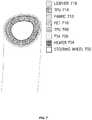
- FIG. 7shows a cross section of the layers of a sensor system as wrapped around a steering wheel.
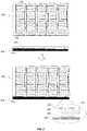
- FIG. 8shows a flattened and exploded view of the layers of a sensor system that may be integrated with a steering wheel as shown in FIG. 7 .
- the layer closest to steering wheel 702is heating layer 704 which includes the steering wheel heating system and its associated electronics.
- a layer of pressure-sensitive adhesive (PSA) 704is provided around heating layer 704 to which the sensor system (including layers 706 - 714 ) is secured.
- PSApressure-sensitive adhesive
- the sensor trace patterns, signal routing traces, and insulators of the sensor arrayare screen printed on a substrate 802 which may be, for example, a flexible PET (polyethylene terephthalate) substrate (e.g., PET 710 ).
- a flexible PET (polyethylene terephthalate) substratee.g., PET 710
- piezoresistive substrate 804e.g., fabric 712
- the piezoresistive materialmay be isolated piezoresistive “patches” of material aligned with individual sensors or groups of sensors. These patches may have shapes that are suitable for a given sensor trace pattern or an arrangement of the corresponding group of sensors.
- piezoresistive substrate 804(or the piezoresistive patches) is (are) adhered to a substrate 806 which may be, for example, a non-permeable, flexible material such as, for example, a thermoplastic polyurethane or TPU, such as those available from Bemis Associates Inc. of Shirley, Mass. (e.g., TPU 714 ).
- the piezoresistive materialmay be adhered to the TPU by selective heating or using a suitable adhesive.
- substrate 802is adhered to a substrate 808 which has substantially the same shape as substrate 806 and may be constructed of the same or substantially similar material (e.g., TPU 708 ).
- Substrate 804is positioned relative to the substrate 802 such that the sections between the cutouts along its edges are aligned with the corresponding sensor trace patterns.
- the substratesare then thermally pressed together so substrate 808 melts into substrate 806 (at least for implementations including TPU substrates), bringing the sensor trace patterns and the piezoresistive material into intimate contact, and forming a hermetic seal around the sensor array and the routing traces leading to sensor circuitry.
- the sealprovides environmental protection for the sensors and traces and helps hold the individual sensor components in position resulting in a robust and tightly integrated unit.
- Environmental protectioncan be particular advantageous for the conductive inks from which the sensors and traces are constructed given their tendency to oxidize and degrade over time when exposed to various environmental contaminants. Such a construction may be useful in protecting the sensor array from environmental conditions and shear forces, but may also enable a wide dynamic range of operation for each of the sensors depending on the thickness and/or rigidity of the materials selected.
- the sensor trace patterns and routing conductors of the sensor arraymay be formed (e.g., printed) on substrate 808 (e.g., TPU 708 ) rather than substrate 802 , eliminating the need for an additional substrate.
- the sensor trace patterns and conductorsmay be formed on one or both sides of substrate 808 .
- the sensor trace patternscould be formed on the underside of substrate 808 (i.e., the side facing the piezoresistive material) with the routing conductors formed on the upper side of substrate 808 .
- connectionscan be made between the sensor trace patterns and their corresponding routing conductors using apertures or vias through substrate 808 .
- the conductors of the sensor arraymay be connected to the sensor circuitry that controls operation of the sensor system in a variety of ways. Two alternative examples are shown in FIG. 8 . It will be appreciated that the two options are depicted together for convenience but that a typical implementation would only include one such option for a given sensor array.
- connector assembly 810(shown in a magnified view) connects with the routing traces of substrate 802 at cutout 812 . This may be accomplished, for example, as described in U.S. Patent Publication No. 2015/0331533 referred to elsewhere herein.
- Connector assembly 810includes sensor circuitry (e.g., as described above with reference to FIG.
- connector assembly 810may be configured to connect with another similar connector assembly of another sensor array (e.g., see connectors assemblies 608 and 610 of FIG. 6 ). Alternatively connector assembly 810 may be configured to connect to other vehicle systems.
- connector 816(shown in a magnified view) connects with the routing traces of substrate 802 at cutout 818 to provide connectivity to sensor circuitry on another assembly (not shown).
- Connector 816might be, for example, any of a variety of flat flexible cable (FFC) connectors, flexible printed circuit (FPC) connectors, ribbon connectors, and the like.
- connector 816is a zero-insertion-force (ZIF) flat flex connector such as, for example, connectors available from Molex Incorporated of Lisle, Ill.
- ZIFzero-insertion-force
- calibrated sensor dataare stored (e.g., in memory 207 of processor 206 ) representing the response of each of the sensors. Such data may also account for changes in individual sensor response over temperature. Calibration data can also account for variations caused by mechanical differences experienced by different sensors based on where each sensor is located in the array. Such data may be used for ensuring consistency in the way the sensor outputs are processed and/or used to represent applied forces. During calibration, the output of each sensor (e.g., as captured by ADC 204 ) is measured for a range of known input forces (and possibly temperatures as well).
- Thismay be done, for example, by placing each sensor on a scale, applying force to that sensor, and recording a value in memory for each of a plurality of ADC values that represents a corresponding value reported by the scale (possibly at a given temperature).
- a set of data points for each sensoris captured (e.g., in a table in memory 207 ) associating ADC values with corresponding forces (e.g., weights in grams or kilograms) as well as possibly temperatures.
- the stored datamay also be in the form of offsets that are applied to the ADC values that normalize the sensors to the same scale of forces.
- the data set for each sensormight capture an offset or force value for every possible value of the ADC output (which may have a resolution of 10 bits or more) and/or for very small changes in temperature. Alternatively, fewer data points may be captured and the sensor circuitry may use interpolation to derive offsets or force values for ADC outputs not represented in the data set. Variations on this theme will be understood by those of skill in the art.
- Both the sensitivity and dynamic range of sensor systems enabled by the present disclosuremay be particularly advantageous for the integration of sensor systems with steering wheels. That is, a multilayer assembly wrapped around a steering wheel (such as the one shown in FIG. 7 ) will typically be wrapped tightly with a significant amount of force exerted on the sensor system in its “relaxed” state, i.e., the state in which no external forces are being exerted on the steering wheel. As will be appreciated, this force will consume much of the potential dynamic range of the sensor system, leaving only a portion of the dynamic range at the upper end of the scale for the detection of forces. Because of this reduction in dynamic range, it is advantageous that, at least for some implementations enabled by the present disclosure, the remaining dynamic range is sufficient to capture the range of forces expected.
- the sensitivity to force enabled by the present disclosurealso allows for sensor systems that can measure forces within that range very precisely, e.g., for every possible value of the ADC output as described above.
- the combination of dynamic range and sensitivity of sensor systems enabled by the present disclosurerepresents significant advantages relative to other sensor technology.
- Generating the set of data points for each sensormay be done by applying the force individually to each sensor using, for example, a device with a footprint that matches the sensor's active area configuration (e.g., see the shape of sensor S 6 of FIG. 1 ). It may also be done by applying force simultaneously over multiple sensors (potentially up to the entire array) using, for example, a precision inflatable bladder that distributes force evenly over the set of sensors. The measurements for a given force can then be captured by activating the sensors sequentially. Other variations will be appreciated by those of skill in the art. Regardless of how the calibration force is applied, what results is data set that the sensor circuitry may use to map the output received from each sensor to a more accurate representation of the force represented. As will be appreciated, this consistency of representation may be important for some applications.
- Crosstalkrefers to contributions to a particular sensor's output attributable to other resistive components of the array in parallel with the resistance of the sensor of interest; often referred to as parasitic resistances.
- ADCanalog-to-digital converter
- V + ⁇ V ⁇represents the ADC input voltage from the sensor (V in ), and V ref the ADC's reference.
- one measurement, V 1is taken with the drive signal of the sensor of interest driven high and the drive signals of all of the other sensors driven low.
- V ⁇ ⁇ 13.3 ⁇ V ⁇ ( R ? ⁇ Rp R ? + R ⁇ ⁇ Rp )
- V ⁇ ⁇ 23.3 ⁇ V ⁇ ( R ⁇ ⁇ Rp R + R ? ⁇ Rp )
- Rrepresents the resistance of the sensor of interest
- R?represents the resistance of the other resistive components of the array contributing to the measurement
- Rprepresents the other resistor of the sensor's voltage divider
- 3.3Vrepresents the reference voltage of the ADC.
- V ⁇ ⁇ 1Rp ⁇ ( 3.3 ⁇ V - V ⁇ ⁇ 2 R + Rp )
- V ⁇ ⁇ 23.3 ⁇ V - V ⁇ ⁇ 1 ⁇ ( R + Rp ) Rp
- RRp ⁇ ( ADC max - Countv 2 Countv 1 - 1 )
- a more accurate determination of Rallows for a more accurate determination of the force applied to the sensor of interest (e.g., using R as an index into a table of resistance vs. force values).
- V 2can be measured without driving the signal line for the sensor of interest low, in which case it can be shown that R, the resistance of the sensor of interest, is given by:
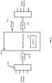
- FIGS. 9 and 10The detection of forces on a particular implementation of a steering wheel sensor system is described with reference to the flowcharts of FIGS. 9 and 10 . As will be appreciated, these processes may be performed, for example, by sensor circuitry (e.g., a processor or controller configured with firmware) as described above with reference to FIG. 2 .
- sensor circuitrye.g., a processor or controller configured with firmware
- the sensors of the arrayare driven sequentially and the resistance of each is captured via the conversion of each sensor's output voltage by an analog-to-digital converter (e.g., ADC 204 ).
- ADC 204analog-to-digital converter
- an ‘update’ flagis set. Within the system's main execution cycle (which occurs in the neighborhood of 55 times per second in one class of implementations), this flag is polled to determine when a new “frame” of data (i.e., a new set of values representing all of the sensors of the array) is ready for analysis.
- the flagis set, the system checks for “grip events” using adjusted thresholding (e.g., as illustrated in FIG. 9 ), and for “swipe events” using delta thresholding (e.g., as illustrated in FIG. 10 ).
- FIG. 9illustrates the process of determining whether a grip event has occurred for one sensor.
- the depicted processis performed for each sensor during each execution cycle (triggered by the flag being set).
- the processshows two paths, one in which a grip event for the sensor has not yet been detected (i.e., the sensor's state is “IDLE”), and one in which a grip event for the sensor has already been detected (i.e., the sensor's state is “GRIPPED_ON”).
- each sensorhas calibration data (in this example an offset associated with its base resistance) that is used to adjust the raw ADC values to arrive at an adjusted ADC reading for each sensor (i.e., “adj”).
- This offset-adjusted valueis substantially proportional to applied force; with no applied force yielding an offset adjusted value of approximately 0 ADC counts (i.e., “hitcount”).
- this offset-adjusted valueis monitored using a finite state machine (FSR) and four thresholds as represented in FIG. 9 .
- FSRfinite state machine
- thresholdscorrespond to “on” and “off” levels for the amplitude of the ADC output representing the magnitude of applied force (i.e., “onAmpThreshold” and “offAmpThreshold”), and “on” and “off” levels for the number of ADC samples representing the duration of applied force (i.e., “onLenThreshold” and “offLenThreshold”).
- FIG. 10illustrates the process of determining whether a swipe event has occurred for one sensor.
- the process depicted in FIG. 10is performed for each sensor during each execution cycle.
- the processshows three paths, one in which a swipe event for the sensor has not yet been detected (i.e., the sensor's state is “IDLE”), one in which a swipe event for the sensor has been detected (i.e., the sensor's state is “SWIPE_ON”), and a third in which a swipe event has terminated (i.e., the sensor's state is “SWIPE_OFF”).
- a swipe eventis detected if a sequence of adjacent sensors are activated in a particular order and/or direction.
- the change or delta in forcei.e., “del”
- the delta valueis not an instantaneous delta, but rather a sum of the differences between the past several samples.
- the number of samples usedis programmable and may be adjusted to suit a particular application and execution cycle. According to a particular class of implementations in which the execution cycle was about 55 cycles per second, about eight samples was found to be an effective number.
- a circular buffer of n deltas between adjacent samplesis maintained and, after each new sample, the delta buffer is summed. This can be summarized by the following equation:
- Swipesare detected using a finite state machine, similar to that used for grip detection, with its own set of thresholds. Each sensor remains in the “IDLE” state unless perturbed (similar to the grip detection state machine) but may advance to one of two states depending upon the sign of the change in force.
- grip and swipe eventscan support recognition of a variety of gestures that can be mapped to various control functions. Examples of gestures include, but are not limited to, single and double grips, swipes (clockwise and counter-clockwise), driver presence, etc.
- grip event detectioncan support recognition of single and double grip gestures that can be analogized to single and double-clicks of a computer mouse and mapped to a similarly broad range of control functions, e.g., such gestures could be mapped to commands to answer a phone call, turn an audio system on or off, interact with a navigation system, etc.
- grip event detectioncan support recognition of the presence of a driver's hands on the steering wheel, and can be detected at any point (or multiple points) around the circumference of the steering wheel.
- Each sensor's offset stored by the sensor circuitrymay change over time due to factors including changes in temperature and gradual compression or decompression of the piezoresistive material. Therefore, according to some implementations, the offset for each sensor is repeatedly recalculated over time to account for this variation. According to a particular implementation, the sensors are sequentially scanned and evaluated on a regular basis to determine whether they are eligible for offset recalculation.
- offset recalculationis not performed because the current ADC value reflects the resistance of the sensor with force applied, rather than the “IDLE” state of the sensor.
- a “hold-off” timerensures that a sensor is given sufficient time to return to a relaxed physical state. Upon the release of a sensor, the hold-off timer is refilled and then decremented with each subsequent scan of the sensor. If the sensor is not depressed again prior to the hold-off timer's expiration, the sensor offset is recalculated.
- the sensor's current raw ADC outputis factored into its current offset using an infinite-impulse response (IIR) filter. This allows the offset to gradually approach its new value while suppressing momentary jumps in ADC output.
- IIRinfinite-impulse response
- a steering wheel sensor systemcould be used for vehicle safety applications, e.g., to ensure that the driver has at least one hand on the wheel. Such a system might issue a warning when it determines that the driver is not touching the wheel or gripping the wheel with sufficient force while the vehicle is running and/or in motion.
- a more sophisticated use of the data from a steering wheel sensor system enabled by the present disclosuremight track variations in grip strength and/or location to detect driver fatigue; a significant factor in many highway accidents in the trucking and transportation industries.
- Steering wheel sensor systemsmight also be useful with self-driving vehicles. For example, in addition to determining that the driver is not touching the wheel or that the driver is fatigued as described above, this information might be used to initiate control of the vehicle by the driverless control system. Control of a vehicle might also be switched from a driverless control system to the vehicle's occupant in response to the steering wheel system sensing that the occupant has grabbed the steering wheel.
- Other vehicle systemsmight be controlled using a steering wheel sensor system.
- navigation, entertainment, communications, cruise control, or environmental systems of a vehiclecould be controlled without requiring the driver to remove her hands from the steering wheel (thus maintaining the driver's focus and improving safety).
- a double squeeze of the steering wheelmight answer a call on a Bluetooth-connected smart phone, or allow a voice command to be acted upon. Sliding the hand along the circumference of the steering wheel could be used to adjust the volume of the vehicle's entertainment system or the temperature of the interior of the vehicle.
- driver hand location determined using a steering wheel sensor systemmight be used to control airbag deployment to reduce airbag injuries.
- a steering wheel sensor systemmight generate statistical information over time about driving habits; information that could be used by a driver to improve things like hand positioning, wheel turning technique, etc. Such information might also be linked or provided to habit tracking applications that employ global positioning system (GPS) technology to develop an understanding of driver behavior based on location and/or time.
- GPSglobal positioning system
- steering wheel sensor systemscould be used in driving simulators and real vehicles for driver training.
- the conductive traces forming a sensor arraymay be formed on a non-conductive or low conductivity substrate (e.g., a fabric or rubber with dielectric properties) which is placed in contact with a flexible piezoresistive substrate in a multi-layer structure such that the conductive traces are in contact with the piezoresistive substrate.
- a non-conductive or low conductivity substratee.g., a fabric or rubber with dielectric properties
- such an arrangementmay function in a manner similar to sensor systems in which the conductive traces are formed directly on the piezoresistive substrate.
- various functionalities described herein in the context of one configuration of a piezoresistive sensor systemmay be readily applied to other configurations.
- functionalities that have been described herein with reference to arrays of piezoresistive sensorsmay be applicable to sensor systems based on other types of force-sensing technology.
- Such functionalitiesinclude, for example, techniques for detecting grip events and swipe events, and techniques for recalculating sensor offsets or other types of sensor calibration data.
- implementationshave been described herein in which sensor arrays are configured along a strip that runs lengthwise along the circumference of the steering wheel with the width of the strip being wrapped around the steering wheel. However, implementations are also contemplated in which such a strip is wrapped around the steering wheel diagonally in a spiraling fashion.
Landscapes
- Engineering & Computer Science (AREA)
- Mechanical Engineering (AREA)
- Transportation (AREA)
- Automation & Control Theory (AREA)
- Chemical & Material Sciences (AREA)
- Combustion & Propulsion (AREA)
- Physics & Mathematics (AREA)
- General Physics & Mathematics (AREA)
- Mathematical Physics (AREA)
- Human Computer Interaction (AREA)
- Force Measurement Appropriate To Specific Purposes (AREA)
- Aviation & Aerospace Engineering (AREA)
- Radar, Positioning & Navigation (AREA)
- Remote Sensing (AREA)
Abstract
Description
where V+−V−represents the ADC input voltage from the sensor (Vin), and Vrefthe ADC's reference. According to a particular class of implementations, it is possible to more accurately determine the value of the resistance of interest by taking multiple measurements for the sensor and combining the measurements mathematically in a way that allows for solving for the resistance of interest.
where R represents the resistance of the sensor of interest, R? represents the resistance of the other resistive components of the array contributing to the measurement, Rp represents the other resistor of the sensor's voltage divider, and 3.3V represents the reference voltage of the ADC. Using substitution, we can find an equation for V1 in terms of V2 (or vice-versa), eliminating the dependence on R? as follows:
Solving either of these equations for R yields:
And since the measurements of V1 and V2 are in units of ADC Counts, we can choose Vref=Vin=3.3V such that the sensor circuitry (e.g., processor206) can determine R, the resistance of the sensor of interest, as follows:
A more accurate determination of R allows for a more accurate determination of the force applied to the sensor of interest (e.g., using R as an index into a table of resistance vs. force values).
Swipes are detected using a finite state machine, similar to that used for grip detection, with its own set of thresholds. Each sensor remains in the “IDLE” state unless perturbed (similar to the grip detection state machine) but may advance to one of two states depending upon the sign of the change in force. If the change in force for a sensor is positive and greater than the “on” amplitude threshold (i.e., “onAmpThreshold”) (1002) for a number of samples (i.e., “onCount”) greater than the “on” length threshold (i.e., “onLenThreshold”) (1004), a “swipeOn” message is generated (1006) and the sensor advances to the “SWIPE_ON” state (1008) until the force stabilizes or reverses sign. In the opposite case where the change in force is negative and greater in magnitude than the “off” amplitude threshold (i.e., “offAmpThreshold”) (1010) for a number of samples (i.e., “offCount”) greater than the “off” length threshold (i.e., “offLenThreshold”) (1012), a “swipeOff” message is generated (1014) and the sensor advances to the “SWIPE_OFF” state (1016). The state machine remains in either of these swiped states until the force stabilizes (“del” equal to zero) or changes sign. At that point the state of the sensor returns to “IDLE” and the system monitors the sensor for further changes in force. In this way, an event can be detected in which a driver moves a finger around the circumference of the steering wheel. It should be noted that although the variables onAmpThreshold, offAmpThreshold, onLenThreshold, and offLenThreshold in
Claims (22)
Priority Applications (1)
| Application Number | Priority Date | Filing Date | Title |
|---|---|---|---|
| US15/690,108US10654486B2 (en) | 2015-06-25 | 2017-08-29 | Sensor systems integrated with steering wheels |
Applications Claiming Priority (3)
| Application Number | Priority Date | Filing Date | Title |
|---|---|---|---|
| US201562184577P | 2015-06-25 | 2015-06-25 | |
| US15/190,089US9827996B2 (en) | 2015-06-25 | 2016-06-22 | Sensor systems integrated with steering wheels |
| US15/690,108US10654486B2 (en) | 2015-06-25 | 2017-08-29 | Sensor systems integrated with steering wheels |
Related Parent Applications (1)
| Application Number | Title | Priority Date | Filing Date |
|---|---|---|---|
| US15/190,089ContinuationUS9827996B2 (en) | 2015-06-25 | 2016-06-22 | Sensor systems integrated with steering wheels |
Publications (2)
| Publication Number | Publication Date |
|---|---|
| US20180015932A1 US20180015932A1 (en) | 2018-01-18 |
| US10654486B2true US10654486B2 (en) | 2020-05-19 |
Family
ID=57586701
Family Applications (2)
| Application Number | Title | Priority Date | Filing Date |
|---|---|---|---|
| US15/190,089ActiveUS9827996B2 (en) | 2015-06-25 | 2016-06-22 | Sensor systems integrated with steering wheels |
| US15/690,108Expired - Fee RelatedUS10654486B2 (en) | 2015-06-25 | 2017-08-29 | Sensor systems integrated with steering wheels |
Family Applications Before (1)
| Application Number | Title | Priority Date | Filing Date |
|---|---|---|---|
| US15/190,089ActiveUS9827996B2 (en) | 2015-06-25 | 2016-06-22 | Sensor systems integrated with steering wheels |
Country Status (2)
| Country | Link |
|---|---|
| US (2) | US9827996B2 (en) |
| WO (1) | WO2016210173A1 (en) |
Cited By (7)
| Publication number | Priority date | Publication date | Assignee | Title |
|---|---|---|---|---|
| US10802641B2 (en) | 2012-03-14 | 2020-10-13 | Bebop Sensors, Inc. | Piezoresistive sensors and applications |
| US10884496B2 (en) | 2018-07-05 | 2021-01-05 | Bebop Sensors, Inc. | One-size-fits-all data glove |
| US11147510B2 (en) | 2014-06-09 | 2021-10-19 | Bebop Sensors, Inc. | Flexible sensors and sensor systems |
| US20220252432A1 (en)* | 2019-07-23 | 2022-08-11 | ZF Automotive Safety Germany GmbH | Steering device sensor, measurement system, operator control system, and steering device |
| US11480481B2 (en) | 2019-03-13 | 2022-10-25 | Bebop Sensors, Inc. | Alignment mechanisms sensor systems employing piezoresistive materials |
| US11525842B2 (en)* | 2018-06-21 | 2022-12-13 | Uchicago Argonne, Llc | Multi-purpose sensors using conductive Iono-elastomers |
| US20240192340A1 (en)* | 2022-12-08 | 2024-06-13 | Continental Autonomous Mobility US, LLC | Sensor calibration method and sensor |
Families Citing this family (29)
| Publication number | Priority date | Publication date | Assignee | Title |
|---|---|---|---|---|
| JP5621090B2 (en) | 2009-10-16 | 2014-11-05 | ビーボップ センサーズ、インコーポレイテッド | Foot-operated controller and computer-implemented method |
| US9965076B2 (en) | 2014-05-15 | 2018-05-08 | Bebop Sensors, Inc. | Piezoresistive sensors and applications |
| US9696833B2 (en) | 2014-05-15 | 2017-07-04 | Bebop Sensors, Inc. | Promoting sensor isolation and performance in flexible sensor arrays |
| US9753568B2 (en) | 2014-05-15 | 2017-09-05 | Bebop Sensors, Inc. | Flexible sensors and applications |
| US9442614B2 (en)* | 2014-05-15 | 2016-09-13 | Bebop Sensors, Inc. | Two-dimensional sensor arrays |
| WO2015179730A1 (en)* | 2014-05-22 | 2015-11-26 | Tk Holdings Inc. | Systems and methods for shielding a hand sensor system in a steering wheel |
| US9710060B2 (en) | 2014-06-09 | 2017-07-18 | BeBop Senors, Inc. | Sensor system integrated with a glove |
| US9915527B2 (en)* | 2014-11-17 | 2018-03-13 | The Boeing Company | Detachable protective coverings and protection methods |
| US9863823B2 (en) | 2015-02-27 | 2018-01-09 | Bebop Sensors, Inc. | Sensor systems integrated with footwear |
| US10082381B2 (en) | 2015-04-30 | 2018-09-25 | Bebop Sensors, Inc. | Sensor systems integrated with vehicle tires |
| US9827996B2 (en) | 2015-06-25 | 2017-11-28 | Bebop Sensors, Inc. | Sensor systems integrated with steering wheels |
| US9721553B2 (en) | 2015-10-14 | 2017-08-01 | Bebop Sensors, Inc. | Sensor-based percussion device |
| US10336361B2 (en) | 2016-04-04 | 2019-07-02 | Joyson Safety Systems Acquisition Llc | Vehicle accessory control circuit |
| RU178840U1 (en)* | 2017-03-31 | 2018-04-19 | Алексей Валерьевич Косцов | Steering wheel cover with pressure sensors |
| US10955301B2 (en) | 2017-10-17 | 2021-03-23 | University Of Maryland, College Park | Two-dimensional center of pressure sensor systems, devices, and methods |
| US10577008B2 (en) | 2017-10-19 | 2020-03-03 | Toyota Research Institute, Inc. | Systems and methods for operator hand position adjustment for airbag deployment |
| KR102019568B1 (en)* | 2017-12-19 | 2019-11-04 | 현대자동차주식회사 | Grip detection system and method of steering wheel for autonomous vehicle |
| CN113454745B (en)* | 2019-03-25 | 2025-03-14 | 阿尔卑斯阿尔派株式会社 | Sensor device and steering wheel |
| US11001167B2 (en)* | 2019-06-14 | 2021-05-11 | Joyson Safety Systems Acquisition Llc | Apparatus and method of producing a sensing substrate |
| FR3115262B1 (en)* | 2020-10-16 | 2023-01-20 | Commissariat Energie Atomique | Multipoint contact detection device and method |
| JP7698948B2 (en)* | 2020-10-29 | 2025-06-26 | オートリブ ディベロップメント エービー | Steering Wheel |
| US11685307B2 (en) | 2021-02-26 | 2023-06-27 | Dsrj Inc. | Turn signal control system and methods |
| WO2022271803A1 (en)* | 2021-06-22 | 2022-12-29 | Cornell University | Modular wearable interface devices |
| US12164730B2 (en) | 2021-11-19 | 2024-12-10 | Alps Alpine Co., Ltd. | Human body sensor system using signal phase shift |
| JP7601023B2 (en) | 2022-02-15 | 2024-12-17 | 豊田合成株式会社 | handle |
| JP7601026B2 (en) | 2022-02-16 | 2024-12-17 | 豊田合成株式会社 | handle |
| JP7626082B2 (en) | 2022-02-16 | 2025-02-04 | 豊田合成株式会社 | handle |
| DE102022105486A1 (en)* | 2022-03-09 | 2023-09-14 | Zf Automotive Germany Gmbh | HAND RECOGNITION DEVICE FOR A STEERING WHEEL DEVICE AND STEERING WHEEL ARRANGEMENT WITH THE HAND RECOGNITION DEVICE |
| FR3148411B1 (en)* | 2023-05-05 | 2025-03-21 | Autoliv Dev | Electrical sheath for a vehicle steering wheel |
Citations (288)
| Publication number | Priority date | Publication date | Assignee | Title |
|---|---|---|---|---|
| JPS4718925U (en) | 1971-03-31 | 1972-11-02 | ||
| US4294014A (en) | 1979-03-27 | 1981-10-13 | Bidegain S.A. | Apparatus for determining the shoe size corresponding to a foot |
| US4438291A (en) | 1982-03-08 | 1984-03-20 | General Electric Company | Screen-printable thermocouples |
| EP0014022B1 (en) | 1979-01-25 | 1984-11-14 | Technisch Advies- en Handelsbureau Hoogstraat C.V. | Foot-size measuring apparatus |
| US4489302A (en) | 1979-09-24 | 1984-12-18 | Eventoff Franklin Neal | Electronic pressure sensitive force transducer |
| US4515404A (en) | 1982-01-21 | 1985-05-07 | Nissan Motor Company, Limited | Seat sliding device |
| EP0211984A1 (en) | 1985-08-19 | 1987-03-04 | Inc. Vpl Research | Computer data entry and manipulation apparatus |
| US4693530A (en) | 1986-09-29 | 1987-09-15 | Amp Incorporated | Shielded elastomeric electric connector |
| US4745301A (en) | 1985-12-13 | 1988-05-17 | Advanced Micro-Matrix, Inc. | Pressure sensitive electro-conductive materials |
| US4790968A (en) | 1985-10-19 | 1988-12-13 | Toshiba Silicone Co., Ltd. | Process for producing pressure-sensitive electroconductive sheet |
| US4852443A (en) | 1986-03-24 | 1989-08-01 | Key Concepts, Inc. | Capacitive pressure-sensing method and apparatus |
| NL8900820A (en) | 1989-04-04 | 1990-11-01 | Hoogstraat Med Tech | Automatic shoe size measuring appts. - measures both inside and outside dimensions using sensors supplying microprocessor |
| US5033291A (en) | 1989-12-11 | 1991-07-23 | Tekscan, Inc. | Flexible tactile sensor for measuring foot pressure distributions and for gaskets |
| JPH0411666A (en) | 1990-04-27 | 1992-01-16 | Toshiba Silicone Co Ltd | Silicone ink |
| US5128880A (en) | 1990-05-11 | 1992-07-07 | Foot Image Technology, Inc. | Foot measurement and footwear sizing system |
| US5131306A (en) | 1989-01-19 | 1992-07-21 | Yamaha Corporation | Automatic music playing piano |
| US5159159A (en) | 1990-12-07 | 1992-10-27 | Asher David J | Touch sensor and controller |
| US5219292A (en) | 1992-04-03 | 1993-06-15 | Motorola, Inc. | Printed circuit board interconnection |
| US5237520A (en) | 1990-05-11 | 1993-08-17 | Foot Image Technology, Inc. | Foot measurement and footwear sizing system |
| US5288938A (en) | 1990-12-05 | 1994-02-22 | Yamaha Corporation | Method and apparatus for controlling electronic tone generation in accordance with a detected type of performance gesture |
| US5316017A (en) | 1992-10-07 | 1994-05-31 | Greenleaf Medical Systems, Inc. | Man-machine interface for a joint measurement system |
| JPH06323929A (en) | 1993-05-13 | 1994-11-25 | Gunze Ltd | Wearing-pressure measuring apparatus |
| US5386720A (en) | 1992-01-09 | 1995-02-07 | Olympus Optical Co., Ltd. | Integrated AFM sensor |
| US5429092A (en) | 1993-02-25 | 1995-07-04 | Mitsubishi Denki Kabushiki Kaisha | Throttle control system |
| JPH08194481A (en) | 1995-01-13 | 1996-07-30 | Roland Corp | Editing method with foot controller |
| US5571973A (en) | 1994-06-06 | 1996-11-05 | Taylot; Geoffrey L. | Multi-directional piezoresistive shear and normal force sensors for hospital mattresses and seat cushions |
| US5578766A (en) | 1994-04-05 | 1996-11-26 | Nec Corporation | Force detector/indicator |
| US5624132A (en) | 1991-04-09 | 1997-04-29 | Trw Vehicle Safety Systems Inc. | Occupant sensing apparatus |
| US5659395A (en) | 1992-06-23 | 1997-08-19 | Footmark, Inc. | Method and apparatus for analyzing feet |
| US5695859A (en) | 1995-04-27 | 1997-12-09 | Burgess; Lester E. | Pressure activated switching device |
| US5729905A (en) | 1995-09-11 | 1998-03-24 | Dwayne L. Mason | Foot measuring apparatus and circuitry to eliminate multiplexes and demultiplexers |
| JPH10198503A (en) | 1996-11-06 | 1998-07-31 | Synaptics Inc | Force detecting touch pad |
| US5822223A (en) | 1997-08-05 | 1998-10-13 | Genovation Inc. | Electronic foot measuring apparatus |
| US5866829A (en) | 1996-12-20 | 1999-02-02 | Pecoraro; Thomas | Pedal rack |
| US5878359A (en) | 1995-06-09 | 1999-03-02 | Nipponsenso Co., Ltd. | Vehicular control device provided with an accelerator detecting device which detects the operation of an accelerator device |
| WO1999020179A1 (en) | 1997-10-23 | 1999-04-29 | Mason, Dwayne, L. | Solid state digital electronic shoe sizer |
| US5943044A (en) | 1996-08-05 | 1999-08-24 | Interlink Electronics | Force sensing semiconductive touchpad |
| US5989700A (en) | 1996-01-05 | 1999-11-23 | Tekscan Incorporated | Pressure sensitive ink means, and methods of use |
| US6032109A (en) | 1996-10-21 | 2000-02-29 | Telemonitor, Inc. | Smart sensor module |
| US6049327A (en) | 1997-04-23 | 2000-04-11 | Modern Cartoons, Ltd | System for data management based onhand gestures |
| US6087930A (en) | 1994-02-22 | 2000-07-11 | Computer Methods Corporation | Active integrated circuit transponder and sensor apparatus for transmitting vehicle tire parameter data |
| US6121869A (en) | 1999-09-20 | 2000-09-19 | Burgess; Lester E. | Pressure activated switching device |
| JP2000267664A (en) | 1999-03-16 | 2000-09-29 | Yamaha Corp | Playing data processing system |
| US6141643A (en) | 1998-11-25 | 2000-10-31 | Harmon; Steve | Data input glove having conductive finger pads and thumb pad, and uses therefor |
| US6155120A (en) | 1995-11-14 | 2000-12-05 | Taylor; Geoffrey L. | Piezoresistive foot pressure measurement method and apparatus |
| US6215055B1 (en) | 1997-08-06 | 2001-04-10 | Darren Saravis | Foot pedal boards for musical instruments |
| US6304840B1 (en) | 1998-06-30 | 2001-10-16 | U.S. Philips Corporation | Fingerless glove for interacting with data processing system |
| US6331893B1 (en) | 1992-06-23 | 2001-12-18 | Footmark, Inc. | Foot analyzer |
| US6360615B1 (en) | 2000-06-06 | 2002-03-26 | Technoskin, Llc | Wearable effect-emitting strain gauge device |
| US6388556B1 (en) | 2000-09-07 | 2002-05-14 | Fujikura Ltd. | Film pressure sensitive resistor and pressure sensitive sensor |
| US20020078757A1 (en) | 2000-06-30 | 2002-06-27 | Jacqueline Hines | Surface-acoustic-wave pressure sensor and associated methods |
| US6452479B1 (en) | 1999-05-20 | 2002-09-17 | Eleksen Limited | Detector contructed from fabric |
| US6486776B1 (en) | 1998-04-14 | 2002-11-26 | The Goodyear Tire & Rubber Company | RF transponder and method of measuring parameters associated with a monitored object |
| US6490515B1 (en) | 1999-01-27 | 2002-12-03 | The Furukawa Electric Co., Ltd. | Passenger detecting apparatus |
| US6531951B2 (en) | 1998-09-11 | 2003-03-11 | I.E.E. International Electronics & Engineering S.A.R.L. | Force sensor |
| US6609054B2 (en) | 2000-05-10 | 2003-08-19 | Michael W. Wallace | Vehicle occupant classification system and method |
| US6626046B2 (en) | 2000-10-30 | 2003-09-30 | Denso Corporation | Pressure-sensitive resistor sensor having electrodes with reduced contact resistance deviation |
| DE10212023A1 (en) | 2002-03-19 | 2003-10-02 | Bosch Gmbh Robert | Sensor cell, especially for use in the sensor mat of a motor vehicle seat, has a piezoelectric resistance element with at least one additional contact so that two resistance measurements are made |
| US6687523B1 (en) | 1997-09-22 | 2004-02-03 | Georgia Tech Research Corp. | Fabric or garment with integrated flexible information infrastructure for monitoring vital signs of infants |
| US20040031180A1 (en) | 2002-06-17 | 2004-02-19 | Dentcho Ivanov | Sensor array for unauthorized user prevention device |
| US20040093746A1 (en) | 2000-08-18 | 2004-05-20 | Salvatore Varsallona | System for measuring the correct size of shoes |
| US20040118619A1 (en) | 2002-12-19 | 2004-06-24 | Delphi Technologies, Inc. | Seat foam humidity compensation for vehicle seat occupant weight detection system |
| US6763320B2 (en) | 2002-08-15 | 2004-07-13 | International Business Machines Corporation | Data input device for individuals with limited hand function |
| US20040183648A1 (en) | 2003-03-21 | 2004-09-23 | Weber Thomas E. | Strain sensors and housings and circuit boards with integrated strain sensors |
| US20040189145A1 (en) | 1999-01-28 | 2004-09-30 | Baruch Pletner | Method and device for vibration control |
| US6815602B2 (en) | 2002-09-30 | 2004-11-09 | Vince De Franco | Electronic percussion instrument with impact position-dependent variable resistive switch |
| US6822635B2 (en) | 2000-01-19 | 2004-11-23 | Immersion Corporation | Haptic interface for laptop computers and other portable devices |
| US20040249536A1 (en) | 2003-03-25 | 2004-12-09 | Aisin Seiki Kabushiki Kaisha | Occupant detecting device |
| US6829942B2 (en) | 2002-06-27 | 2004-12-14 | Denso Corporation | Pressure sensor |
| US20040252007A1 (en) | 2000-05-18 | 2004-12-16 | David Lussey | Flexible switching devices |
| US20050072249A1 (en) | 2003-08-27 | 2005-04-07 | Aisin Seiki Kabushiki Kaisha | Occupant classification device |
| US20050109095A1 (en) | 2003-11-20 | 2005-05-26 | Sinnett Jay C. | Saw transducer interface to pressure sensing diaphragm |
| US20050220673A1 (en) | 2002-02-22 | 2005-10-06 | Jacob Thaysen | Sensor comprising an array of pieroresistors |
| US6964205B2 (en) | 2003-12-30 | 2005-11-15 | Tekscan Incorporated | Sensor with plurality of sensor elements arranged with respect to a substrate |
| US7037268B1 (en) | 1999-03-01 | 2006-05-02 | Medacoustics, Inc. | Low profile acoustic sensor arry and sensors with pleated transmission lines and related methods |
| US20060103192A1 (en) | 2004-11-18 | 2006-05-18 | Peter Norton | Load cell and seat occupant weight sensing system |
| US7066887B2 (en) | 2003-10-21 | 2006-06-27 | Vermon | Bi-plane ultrasonic probe |
| US20060150752A1 (en) | 2003-06-23 | 2006-07-13 | Holger Lorenz | Seat occupancy sensor |
| US20060192417A1 (en) | 2005-02-24 | 2006-08-31 | Siemens Aktiengesellschaft | Seat occupation detection mat |
| US7109068B2 (en) | 2004-08-31 | 2006-09-19 | Micron Technology, Inc. | Through-substrate interconnect fabrication methods |
| US20060209050A1 (en) | 2003-04-16 | 2006-09-21 | Iee International Electronics & Engineering S.A. | Position detection device |
| US7113856B2 (en) | 2001-08-17 | 2006-09-26 | Iee International Electronics & Engineering S.A. | Method for the classification of an occupancy status of a vehicle seat |
| US7138976B1 (en) | 2000-07-13 | 2006-11-21 | Rutgers, The State University Of New Jersey | Hand force feedback and sensing system |
| US7157640B2 (en) | 2003-06-17 | 2007-01-02 | Baggs Lloyd R | Undersaddle pickup for stringed musical instrument |
| US7162344B2 (en) | 2003-11-20 | 2007-01-09 | Honda Motor Co., Ltd. | Occupant detection system |
| KR20070008500A (en) | 2006-12-29 | 2007-01-17 | 이학범 | Ultrasonic Foot Size Automatic Measuring System |
| JP2007503052A (en) | 2003-08-18 | 2007-02-15 | アップル・コンピューター・インコーポレーテッド | Movable touchpad with added features |
| WO2007024875A2 (en) | 2005-08-22 | 2007-03-01 | Jay White | Method and system for providing customized footwear to a consumer |
| US20070063992A1 (en) | 2005-09-17 | 2007-03-22 | Lundquist Paul B | Finger-keyed human-machine interface device |
| US20070129776A1 (en) | 2005-10-20 | 2007-06-07 | Light Sciences Llc | External wearable light therapy treatment systems |
| US20070151348A1 (en) | 2003-12-11 | 2007-07-05 | Mark Zdeblick | Pressure sensor circuits |
| US20070188179A1 (en) | 2006-02-10 | 2007-08-16 | Deangelis Alfred R | Printed capacitive sensor |
| US20070202765A1 (en) | 2004-03-31 | 2007-08-30 | Koninklijke Philips Electronics, N.V. | Textile form touch sensor |
| US20070234888A1 (en) | 2005-10-03 | 2007-10-11 | Audiobrax Industria E Comercio De Produtos Eletronicos S/A | Rhythmic device for the production, playing, accompaniment and evaluation of sounds |
| CN200980381Y (en) | 2006-08-31 | 2007-11-28 | 陈波 | Device for selecting shoe size according with measured foot size |
| US7302866B1 (en) | 2007-01-10 | 2007-12-04 | The Boeing Company | Device, system, and method for structural health monitoring |
| US7311009B2 (en) | 2004-11-17 | 2007-12-25 | Lawrence Livermore National Security, Llc | Microelectromechanical systems contact stress sensor |
| US7332670B2 (en) | 2004-07-27 | 2008-02-19 | Yamaha Corporation | Automatic player exactly bringing pedal to half point, musical instrument equipped therewith and method used therein |
| US20080046152A1 (en) | 2004-08-27 | 2008-02-21 | Wataru Ohtake | Seat Condition Detection Device, and Illumination Direction Adjustment Device for Vehicle Headlamp |
| US20080069412A1 (en) | 2006-09-15 | 2008-03-20 | Champagne Katrina S | Contoured biometric sensor |
| WO2008032661A1 (en) | 2006-09-12 | 2008-03-20 | National Institute Of Advanced Industrial Science And Technology | Distribution value measuring method and measuring system using distribution value sensor therefore |
| JP2008515008A (en) | 2004-10-01 | 2008-05-08 | オーディオブラックス インドゥストリア エ コメルシオ デ プロドゥトス エレトロニコス ソシエダッド アノニマ | Rhythm device for sound generation, performance, accompaniment and evaluation |
| US20080158145A1 (en) | 2007-01-03 | 2008-07-03 | Apple Computer, Inc. | Multi-touch input discrimination |
| US7409256B2 (en) | 2005-12-16 | 2008-08-05 | Industrial Technology Research Institute | Footwear measurement and footwear manufacture systems and methods |
| US20080189827A1 (en) | 2005-04-20 | 2008-08-14 | David Bauer | Golf Training Glove |
| US20080254824A1 (en) | 2005-02-02 | 2008-10-16 | Aurelio Rotolo Moraes | Mobile Communication Device with Musical Instrument Functions |
| US7439465B2 (en) | 2005-09-02 | 2008-10-21 | White Electronics Designs Corporation | Switch arrays and systems employing the same to enhance system reliability |
| KR100865148B1 (en) | 2006-12-14 | 2008-10-24 | 이학범 | Foot size automatic measuring device |
| US20090013793A1 (en) | 2007-07-09 | 2009-01-15 | Samsung Electronics Co., Ltd. | Pressure sensor for measuring blood pressure and method of fabricating the same |
| US7483866B2 (en) | 2005-12-19 | 2009-01-27 | Trw Automotive U.S. Llc | Subclass partitioning in a pattern recognition classifier for controlling deployment of an occupant restraint system |
| US7493230B2 (en) | 2006-06-06 | 2009-02-17 | Aetrex Worldwide, Inc. | Method and apparatus for customizing insoles for footwear |
| US20090049980A1 (en) | 2003-07-25 | 2009-02-26 | Ravi Sharma | Inverted keyboard instrument and method of playing the same |
| US7536794B2 (en) | 2005-05-20 | 2009-05-26 | Bivab, Llc | Foot measurement, alignment and evaluation device |
| US20090134966A1 (en) | 2007-11-27 | 2009-05-28 | Interlink Electronics, Inc. | Pre-loaded force sensing resistor and method |
| US20090237374A1 (en) | 2008-03-20 | 2009-09-24 | Motorola, Inc. | Transparent pressure sensor and method for using |
| US7608776B2 (en) | 2003-12-15 | 2009-10-27 | Ludwig Lester F | Modular structures facilitating field-customized floor controllers |
| US20090272197A1 (en) | 2006-07-06 | 2009-11-05 | Miguel Ridao Granado | Torsion and/or Tension And/or Pressure Textile Sensor |
| US20090301190A1 (en) | 2008-06-09 | 2009-12-10 | Rochester Gauges, Inc. | Capacitive sensor assembly for determining relative position |
| US20090303400A1 (en) | 2008-06-10 | 2009-12-10 | Industrial Technology Research Institute | Functional device array with self-aligned electrode structures and fabrication methods thereof |
| WO2009155891A1 (en) | 2008-06-25 | 2009-12-30 | Conti Temic Microelectronic Gmbh | Circuit and method for controlling a trimorphemic piezoelectric actuator |
| US20100066572A1 (en) | 2008-09-18 | 2010-03-18 | Microsoft Corporation | Resistive switch matrix |
| US7719007B2 (en) | 2008-04-30 | 2010-05-18 | Milliken & Company | Flexible electroluminescent capacitive sensor |
| US20100123686A1 (en) | 2008-11-19 | 2010-05-20 | Sony Ericsson Mobile Communications Ab | Piezoresistive force sensor integrated in a display |
| US7726199B2 (en) | 2008-04-08 | 2010-06-01 | Wisconsin Alumni Research Foundation | Dielectrostrictive sensor for measuring deformation |
| US20100134327A1 (en) | 2008-11-28 | 2010-06-03 | Dinh Vincent Vinh | Wireless haptic glove for language and information transference |
| US20100149108A1 (en) | 2008-12-11 | 2010-06-17 | Steve Porter Hotelling | Single layer touch panel with segmented drive and sense electrodes |
| US7754956B2 (en) | 2007-12-12 | 2010-07-13 | Force Ten International Llc | Programmable system to integrate generated signals with signals from a musical instrument |
| US20100179724A1 (en) | 2007-06-20 | 2010-07-15 | David Alan Weston | Autolocation of all tire id's on a multi-axle vehicle |
| US20100199777A1 (en) | 2009-02-10 | 2010-08-12 | Hooper Stephen R | Exposed Pad Backside Pressure Sensor Package |
| US20100242274A1 (en) | 2009-03-30 | 2010-09-30 | Microsoft Corporation | Detecting touch on a curved surface |
| US20100274447A1 (en) | 2008-05-05 | 2010-10-28 | Stumpf John F | Transducer matrix film |
| US20100286951A1 (en) | 2008-01-07 | 2010-11-11 | Aetrex Worldwide Inc. | Foot measuring device |
| US20100292945A1 (en) | 2009-05-13 | 2010-11-18 | Joseph Kurth Reynolds | Capacitive sensor device |
| US20100315337A1 (en) | 2009-06-16 | 2010-12-16 | Bran Ferren | Optical capacitive thumb control with pressure sensor |
| US20110005090A1 (en) | 2008-04-11 | 2011-01-13 | Lee Fred S | Displacement sensing using a flexible substrate |
| JP2011502313A (en) | 2007-11-07 | 2011-01-20 | エーティーラブ・インコーポレーテッド | Touch panel device and contact position detection method of the device |
| US20110088536A1 (en) | 2009-10-16 | 2011-04-21 | Kesumo Llc | Foot-operated controller |
| US20110088535A1 (en) | 2008-03-11 | 2011-04-21 | Misa Digital Pty Ltd. | digital instrument |
| US20110107771A1 (en) | 2009-11-05 | 2011-05-12 | Columbia Sportswear North America, Inc. | Footwear temperature control method and apparatus |
| US20110141052A1 (en) | 2009-12-10 | 2011-06-16 | Jeffrey Traer Bernstein | Touch pad with force sensors and actuator feedback |
| US20110153261A1 (en) | 2009-12-21 | 2011-06-23 | Electronics And Telecommunications Research Institute | Smart footwear and operating method thereof |
| US7984544B2 (en) | 2005-06-16 | 2011-07-26 | Ilya D. Rosenberg | Method for manufacturing long force sensors using screen printing technology |
| CN201920728U (en) | 2010-12-27 | 2011-08-10 | 北京汉林信通信息技术有限公司 | Automatic height, weight and foot length measuring device for people |
| US20110199284A1 (en) | 2010-02-17 | 2011-08-18 | Microvision, Inc. | Piezoresistive Sensors for MEMS Device Having Rejection of Undesired Motion |
| US20110221564A1 (en) | 2010-03-12 | 2011-09-15 | Almax Manufacturing Corporation | Switch using variable resistance layer to control state |
| US20110241850A1 (en) | 2010-03-31 | 2011-10-06 | Tk Holdings Inc. | Steering wheel sensors |
| US20110246028A1 (en) | 2010-04-02 | 2011-10-06 | Tk Holdings Inc. | Steering wheel with hand pressure sensing |
| US20110260994A1 (en) | 2010-03-19 | 2011-10-27 | Xavier Pierre-Emmanuel Saynac | Systems and methods for determining the location and pressure of a touchload applied to a touchpad |
| US20110271772A1 (en) | 2007-04-23 | 2011-11-10 | Sierra Scientific Instruments, Inc. | Suspended membrane pressure sensing array |
| US20110279409A1 (en) | 2010-05-14 | 2011-11-17 | Salaverry Ricardo R | System and Method for Detecting Locations of Touches on a Touch Sensor |
| US20110292049A1 (en) | 2010-05-25 | 2011-12-01 | Glenn Muravsky | Motion sensor |
| US20110302694A1 (en) | 2008-04-03 | 2011-12-15 | University Of Washington | Clinical force sensing glove |
| US20120007831A1 (en) | 2009-10-09 | 2012-01-12 | Egalax_Empia Technology Inc. | Method and device for position detection |
| US20120024132A1 (en) | 2010-07-27 | 2012-02-02 | Pure Imagination Llc | Simulated percussion instrument |
| US20120026124A1 (en) | 2010-07-31 | 2012-02-02 | Motorola, Inc. | Touch screen rendering system and method of operation thereof |
| US8109149B2 (en) | 2004-11-17 | 2012-02-07 | Lawrence Livermore National Security, Llc | Contact stress sensor |
| US8120232B2 (en) | 2009-01-20 | 2012-02-21 | Palo Alto Research Center Incorporated | Sensors and actuators using piezo polymer layers |
| US8117922B2 (en) | 2006-09-21 | 2012-02-21 | Msd Consumer Care, Inc. | Footcare product dispensing kiosk |
| US8127623B2 (en) | 2005-05-18 | 2012-03-06 | Pressure Profile Systems Inc. | Capacitive tactile tile sensor |
| US20120055257A1 (en) | 2010-09-08 | 2012-03-08 | Micropen Technologies Corporation | Pressure sensing or force generating device |
| CN102406280A (en) | 2011-12-21 | 2012-04-11 | 夏彬 | Device for selecting size by body measurement |
| US20120090408A1 (en) | 2010-10-14 | 2012-04-19 | Industrial Technology Research Institute | Method for manufacturing piezoresistive material, piezoresistive composition and pressure sensor device |
| US8162857B2 (en) | 2006-10-11 | 2012-04-24 | Koninklijke Philips Electronics N.V. | Limb movement monitoring system |
| US8161826B1 (en) | 2009-03-05 | 2012-04-24 | Stryker Corporation | Elastically stretchable fabric force sensor arrays and methods of making |
| CN102551728A (en) | 2010-12-27 | 2012-07-11 | 北京汉林信通信息技术有限公司 | Automatic measuring device for heights, body weights and foot lengths of persons |
| US20120198949A1 (en) | 2006-09-21 | 2012-08-09 | Msd Consumer Care, Inc. | Footcare product dispensing kiosk |
| US8250934B2 (en) | 2009-02-10 | 2012-08-28 | Honda Motor Co., Ltd. | Multi-axis force sensor and acceleration sensor |
| CN202396601U (en) | 2011-12-21 | 2012-08-29 | 夏彬 | Body-measuring and size-selecting device |
| US20120222498A1 (en) | 2011-03-04 | 2012-09-06 | Hm Technology International Limited | Force Sensor |
| JP2012521550A (en) | 2009-03-25 | 2012-09-13 | ペラテック リミテッド | Sensor |
| US8274485B2 (en) | 2008-09-30 | 2012-09-25 | Tpk Touch Solutions Inc. | Touch position detection method for touch control device |
| US20120283979A1 (en) | 2009-12-21 | 2012-11-08 | Koninklijke Philips Electronics N.V. | Sensor system |
| JP2012220315A (en) | 2011-04-07 | 2012-11-12 | Seiko Epson Corp | Pressure detection device |
| US20120296528A1 (en) | 2011-05-20 | 2012-11-22 | Matthias Marcus Wellhoefer | Haptic steering wheel, steering-wheel system and driver assistance system for a motor vehicle |
| US20120297885A1 (en) | 2011-05-23 | 2012-11-29 | Universal Cement Corporation | Preloaded pressure sensor module |
| US20120299127A1 (en) | 2011-05-27 | 2012-11-29 | Denso Corporation | Dynamic quantity sensor device and manufacturing method of the same |
| US20120312102A1 (en) | 2011-06-07 | 2012-12-13 | The University Of Texas System | Force sensing device and methods for preparing and uses thereof |
| US20120323501A1 (en) | 2011-05-20 | 2012-12-20 | The Regents Of The University Of California | Fabric-based pressure sensor arrays and methods for data analysis |
| US8346684B2 (en) | 2006-07-28 | 2013-01-01 | Iee International Electronics & Engineering S.A. | Pattern classification method |
| US20130009905A1 (en) | 2011-07-06 | 2013-01-10 | Sharp Kabushiki Kaisha | Dual-function transducer for a touch panel |
| US20130055482A1 (en) | 2011-09-02 | 2013-03-07 | Fiat Group Automobiles S.P.A. | Method for designing a protective glove to be used in performing a cycle of manual operations in an industrial production line, and glove designed by this method |
| US20130082970A1 (en) | 2010-06-11 | 2013-04-04 | 3M Innovative Properties Company | Positional touch sensor with force measurement |
| US20130085394A1 (en) | 2011-10-04 | 2013-04-04 | Sonivate Medical, Inc. | Glove with integrated sensor |
| US20130113704A1 (en) | 2011-11-04 | 2013-05-09 | The Regents Of The University Of California | Data fusion and mutual calibration for a sensor network and a vision system |
| US8448530B2 (en) | 2009-03-27 | 2013-05-28 | CSEM Centre Suisee d'Electronique et de Microtechnique SA-Recherche et Developpement | Roll-to-roll compatible pressure sensitive event sensing label |
| US20130165809A1 (en) | 2010-07-29 | 2013-06-27 | Digisense Ltd. | Monitoring physiological condition of a subject |
| US20130192071A1 (en) | 2012-01-30 | 2013-08-01 | Heapsylon LLC | Sensors, interfaces and sensor systems for data collection and integrated remote monitoring of conditions at or near body surfaces |
| US20130203201A1 (en) | 2010-09-13 | 2013-08-08 | David Thomas Britton | Printed Temperature Sensor |
| US20130211208A1 (en) | 2011-03-08 | 2013-08-15 | Vijay K. Varadan | Smart materials, dry textile sensors, and electronics integration in clothing, bed sheets, and pillow cases for neurological, cardiac and/or pulmonary monitoring |
| US20130214365A1 (en) | 2012-02-21 | 2013-08-22 | Freescale Semiconductor, Inc. | Mems pressure transducer assembly and method of packaging same |
| US8536880B2 (en) | 2007-08-26 | 2013-09-17 | Atmel Corporation | Capacitive sensor with additional noise-registering electrode |
| US20130239787A1 (en) | 2012-03-14 | 2013-09-19 | Kesumo Llc | Multi-touch pad controller |
| CN203234132U (en) | 2013-05-12 | 2013-10-16 | 夏彬 | Foot length measuring device |
| US20130275057A1 (en) | 2010-10-12 | 2013-10-17 | Tactonic Technologies, Llc | Sensor Having a Mesh Layer with Protrusions, and Method |
| US20130274985A1 (en) | 2012-04-16 | 2013-10-17 | GM Global Technology Operations LLC | System and method for vehicle lateral control |
| US8587422B2 (en) | 2010-03-31 | 2013-11-19 | Tk Holdings, Inc. | Occupant sensing system |
| WO2013181474A1 (en) | 2012-05-30 | 2013-12-05 | Medisens Wireless, Inc. | Pressure signature based biometric systems, sensor assemblies and methods |
| US20130327560A1 (en) | 2011-02-24 | 2013-12-12 | Fujifilm Corporation | Electroconductive sheet and touch panel |
| US20130340598A1 (en) | 2012-06-22 | 2013-12-26 | Ronald G. Marquez | Impact Responsive Portable Electronic Drumhead |
| EP2682724A1 (en) | 2012-07-04 | 2014-01-08 | Sensing Tex, S.L. | A large-area extensible pressure sensor for textiles surfaces |
| US20140007706A1 (en) | 2010-07-30 | 2014-01-09 | Delphi Technologies, Inc. | Pressure sensitive transducer assembly and control method for a system including such an assembly |
| US20140013865A1 (en) | 2012-07-13 | 2014-01-16 | Nokia Corporation | Apparatus for Sensing |
| US20140026678A1 (en) | 2011-01-25 | 2014-01-30 | Francis Cannard | Device Intended For Measuring Pressure From A Flexible, Foldable, And/Or Extendable Object Made Of A Textile Material And Comprising A Measurement Device |
| KR101362742B1 (en) | 2012-12-21 | 2014-02-13 | 현대오트론 주식회사 | A tire management system and a vehicle comprising the same |
| US20140090488A1 (en) | 2012-09-29 | 2014-04-03 | Stryker Corporation | Flexible Piezocapacitive And Piezoresistive Force And Pressure Sensors |
| US20140104776A1 (en) | 2012-10-17 | 2014-04-17 | James E. Clayton | Rigid circuit board with flexibly attached module |
| WO2014058473A1 (en) | 2012-10-09 | 2014-04-17 | Mc10, Inc. | Conformal electronics integrated with apparel |
| US20140104792A1 (en) | 2012-10-11 | 2014-04-17 | Apple Inc. | Devices Having Flexible Printed Circuits With Bent Stiffeners |
| JP2014077662A (en) | 2012-10-09 | 2014-05-01 | Takano Co Ltd | Distribution quantity sensor and distribution quantity measurement system |
| US20140125124A1 (en) | 2012-11-05 | 2014-05-08 | Nissan North America, Inc. | Vehicle horn control assembly |
| US20140130593A1 (en) | 2012-11-13 | 2014-05-15 | Industrial Technology Research Institute | Pressure measurement structure |
| US20140150573A1 (en) | 2011-01-13 | 2014-06-05 | Francis Cannard | Device for Measuring Pressure from a Flexible, Pliable, and/or Extensible Object Made from a Textile Material Comprising a Measurement Device |
| KR20140071693A (en) | 2012-12-04 | 2014-06-12 | 정홍기 | Method for measuring foot size using autofocus |
| US20140182170A1 (en) | 2012-12-19 | 2014-07-03 | New Balance Athletic Shoe, Inc. | Customized footwear, and systems and methods for designing and manufacturing same |
| US20140195023A1 (en) | 2011-08-09 | 2014-07-10 | Nederlandse Organisatie Voor Toegepast-Natuurweten Schappelijk Onderzoek Tno | Method and system for feedback on running style field and background of the invention |
| US20140215684A1 (en) | 2013-02-07 | 2014-08-07 | Timothy J. Hardy | Pressure Sensing Glove |
| US20140222173A1 (en) | 2013-02-01 | 2014-08-07 | Nike, Inc. | System and method for analyzing athletic activity |
| US20140238153A1 (en) | 2011-09-24 | 2014-08-28 | President And Fellows Of Harvard College | Artificial skin and elastic strain sensor |
| US20140240214A1 (en) | 2013-02-26 | 2014-08-28 | Jiake Liu | Glove Interface Apparatus for Computer-Based Devices |
| US20140264407A1 (en) | 2013-03-15 | 2014-09-18 | Michael A. Tischler | Stress relief for array-based electronic devices |
| US20140318699A1 (en) | 2012-09-11 | 2014-10-30 | Gianluigi LONGINOTTI-BUITONI | Methods of making garments having stretchable and conductive ink |
| US8880358B2 (en) | 2010-04-16 | 2014-11-04 | Thomas J. Cunningham | Sensing device |
| US8892051B2 (en) | 2011-03-25 | 2014-11-18 | General Motors Llc | Telematics provisioning system for deactivated devices |
| RU2533539C1 (en) | 2013-05-27 | 2014-11-20 | Федеральное государственное бюджетное образовательное учреждение высшего профессионального образования "Тверской государственный университет" | Piezoelectric shock pick-up |
| US20140347076A1 (en) | 2012-02-10 | 2014-11-27 | 3M Innovative Properties Company | Touch sensor electrode with patterned electrically isolated regions |
| US8947889B2 (en) | 2010-10-14 | 2015-02-03 | Lockheed Martin Corporation | Conformal electromagnetic (EM) detector |
| US20150035743A1 (en) | 2013-07-31 | 2015-02-05 | Plantronics, Inc. | Wrist Worn Platform for Sensors |
| US8950265B2 (en) | 2011-12-29 | 2015-02-10 | Parker-Hannifin Corporation | Electroactive polymer based pressure sensor |
| US8964205B2 (en) | 2012-03-26 | 2015-02-24 | SCREEN Holdings Co., Ltd. | Print control apparatus, inkjet printing apparatus, print control method, and recording medium with data compression/decompression |
| US8970513B2 (en) | 2010-10-11 | 2015-03-03 | Samsung Electronics Co., Ltd. | Touch panel having deformable electroactive polymer actuator |
| US20150084873A1 (en) | 2013-09-25 | 2015-03-26 | Lenovo (Singapore) Pte. Ltd. | Integrating multiple different touch based inputs |
| US20150086955A1 (en) | 2012-05-03 | 2015-03-26 | Lauren H. Poniatowski | Systems and methods for analyzing surgical techniques |
| US20150130698A1 (en) | 2013-11-13 | 2015-05-14 | Symbol Technologies, Inc. | Wearable glove electronic device |
| US9112058B2 (en) | 2010-09-10 | 2015-08-18 | The Board Of Trustees Of The Leland Stanford Junior University | Interface apparatus and methods |
| US20150231991A1 (en) | 2014-02-17 | 2015-08-20 | Lear Corporation | Seat cushion length extender with sensor |
| US9116569B2 (en) | 2008-11-26 | 2015-08-25 | Blackberry Limited | Touch-sensitive display method and apparatus |
| US20150248159A1 (en) | 2013-06-19 | 2015-09-03 | Florida State University Research Foundation, Inc. | Piezoresistive sensors and methods |
| US9164586B2 (en) | 2012-11-21 | 2015-10-20 | Novasentis, Inc. | Haptic system with localized response |
| US9182302B2 (en) | 2012-07-06 | 2015-11-10 | Samsung Electronics Co., Ltd. | Apparatus and method for measuring tactile sensation |
| US20150330855A1 (en) | 2014-05-15 | 2015-11-19 | Henry J. Daniecki | Lower limb force sensing system |
| US20150331523A1 (en) | 2014-05-15 | 2015-11-19 | Bebop Sensors, Inc. | Two-dimensional sensor arrays |
| US20150331522A1 (en) | 2014-05-15 | 2015-11-19 | Kesumo Llc | Piezoresistive sensors and applications |
| US20150331512A1 (en) | 2014-05-15 | 2015-11-19 | Bebop Sensors, Inc. | Promoting sensor isolation and performance in flexible sensor arrays |
| US20150328492A1 (en) | 2014-05-14 | 2015-11-19 | Dean R. Marriott | Gloves For Adjusting and Controlling Resistance to Hand Movement, And Related Methods Thereof |
| US20150331533A1 (en) | 2014-05-15 | 2015-11-19 | Bebop Sensors, Inc. | Flexible sensors and applications |
| WO2015175317A1 (en) | 2014-05-15 | 2015-11-19 | Bebop Sensors, Inc. | Piezoresistive sensors and applications |
| US20150370396A1 (en) | 2012-12-14 | 2015-12-24 | Apple Inc. | Force Sensing Based on Capacitance Changes |
| US20160052131A1 (en) | 2014-08-22 | 2016-02-25 | President And Fellows Of Harvard College | Flexible and Stretchable Electronic Strain-limited Layer for Soft Actuators |
| US20160054798A1 (en) | 2014-08-22 | 2016-02-25 | Sony Computer Entertainment Inc. | Glove Interface Object |
| US20160070347A1 (en) | 2014-06-09 | 2016-03-10 | Bebop Sensors, Inc. | Sensor system integrated with a glove |
| US20160073539A1 (en) | 2014-09-05 | 2016-03-10 | Dimensional Industries, Inc. | Flexible printed circuit board assembly for electronic devices |
| WO2016070078A1 (en) | 2014-10-30 | 2016-05-06 | Bebop Sensors, Inc. | Sensor system integrated with a glove |
| US20160147352A1 (en) | 2014-01-13 | 2016-05-26 | Apple Inc. | Temperature Compensating Transparent Force Sensor Having a Compliant Layer |
| US20160162022A1 (en) | 2014-12-08 | 2016-06-09 | Rohit Seth | Wearable wireless hmi device |
| US20160169754A1 (en) | 2014-12-12 | 2016-06-16 | Regents Of The University Of Minnesota | Articles of handwear for sensing forces applied to medical devices |
| US20160175186A1 (en) | 2014-12-22 | 2016-06-23 | John H. Shadduck | Wearable sensing and actuator systems, and methods of use |
| US20160187973A1 (en) | 2014-12-30 | 2016-06-30 | Stmicroelectronics Pte Ltd | Flexible smart glove |
| US20160209441A1 (en) | 2011-10-28 | 2016-07-21 | President And Fellows Of Harvard College | Capacitive, paper-based accelerometers and touch sensors |
| US9413376B2 (en) | 2014-11-11 | 2016-08-09 | Helio Technology Inc. | Angle encoder and a method of measuring an angle using same |
| US20160238547A1 (en) | 2013-10-15 | 2016-08-18 | 1835963 Alberta Ltd. | Sensing Element Compositions and Sensor System for Detecting and Monitoring Structures for Hydrocarbons |
| US20160246369A1 (en) | 2015-02-20 | 2016-08-25 | Sony Computer Entertainment Inc. | Magnetic tracking of glove fingertips |
| US20160252412A1 (en) | 2015-02-27 | 2016-09-01 | Bebop Sensors, Inc. | Sensor systems integrated with footwear |
| US20160270727A1 (en) | 2014-06-17 | 2016-09-22 | MAD Apparel, Inc. | Garment integrated electrical interface system and method of manufacture |
| US20160278709A1 (en) | 2013-09-16 | 2016-09-29 | Sensing Tex, S.L. | Textile piezoresistive sensor and heartbeat and/or respiratory rate detection system |
| US20160313798A1 (en) | 2015-04-22 | 2016-10-27 | Medibotics Llc | Nerd of the Rings -- Devices for Measuring Finger Motion and Recognizing Hand Gestures |
| US9480582B2 (en) | 2005-03-23 | 2016-11-01 | Ossur Hf | System and method for conscious sensory feedback |
| WO2016176307A1 (en) | 2015-04-30 | 2016-11-03 | Bebop Sensors, Inc. | Sensor systems integrated with vehicle tires |
| US20160340534A1 (en) | 2015-05-22 | 2016-11-24 | Board Of Regents, The University Of Texas System | Inks, piezoresistive sensors, and conductive materials on flexible substrates |
| US20160375910A1 (en) | 2015-06-25 | 2016-12-29 | Bebop Sensors, Inc. | Sensor systems integrated with steering wheels |
| US20170000369A1 (en) | 2015-07-03 | 2017-01-05 | Elwha Llc | Electrocardiogram systems and related methods |
| US9582035B2 (en) | 2014-02-25 | 2017-02-28 | Medibotics Llc | Wearable computing devices and methods for the wrist and/or forearm |
| US20170056644A1 (en) | 2015-08-05 | 2017-03-02 | Tony CHAHINE | Textile-based product |
| US20170086519A1 (en) | 2014-05-15 | 2017-03-30 | Sensoria, Inc. | Gloves with sensors for monitoring and analysis of position, pressure and movement |
| US9612102B2 (en) | 2015-04-17 | 2017-04-04 | Bend Labs, Inc | Compliant multi-region angular displacement and strain sensors |
| US20170110103A1 (en) | 2015-10-14 | 2017-04-20 | Kesumo, Llc | Sensor-based percussion device |
| US20170108929A1 (en) | 2015-04-28 | 2017-04-20 | Morgan Walker Sinko | System and Method for Full Motion Capture and Haptic Feedback Suite |
| US20170127736A1 (en) | 2015-11-05 | 2017-05-11 | Impact Tech Labs Limited | Wearable garment |
| US9682856B2 (en) | 2011-08-01 | 2017-06-20 | President And Fellows Of Harvard College | MEMS force sensors fabricated using paper substrates |
| US20170176267A1 (en) | 2015-12-17 | 2017-06-22 | Oculus Vr, Llc | Indexable strain sensor |
| US9696223B2 (en) | 2012-09-17 | 2017-07-04 | Tk Holdings Inc. | Single layer force sensor |
| JP2017518338A (en) | 2014-06-16 | 2017-07-06 | バイオミューン・カンパニー | Dual adjuvant vaccine composition, preparation and use |
| US20170215495A1 (en) | 2014-10-17 | 2017-08-03 | Yamaha Corporation | Data Glove |
| US9756895B2 (en) | 2012-02-22 | 2017-09-12 | Nike, Inc. | Footwear having sensor system |
| US20170305301A1 (en) | 2016-04-22 | 2017-10-26 | Bebop Sensors, Inc. | Vehicle seat sensor systems for use with occupant classification systems |
| US20170303853A1 (en) | 2014-06-09 | 2017-10-26 | Bebop Sensors, Inc. | Sensor system integrated with a glove |
| US9851267B1 (en) | 2016-06-01 | 2017-12-26 | Microsoft Technology Licensing, Llc | Force-sensing element |
| US9970832B2 (en) | 2013-06-24 | 2018-05-15 | Snu R&Db Foundation | Manufacturing method of strain sensor, strain sensor and motion sensing apparatus using the strain sensor |
| US10046671B2 (en) | 2015-08-14 | 2018-08-14 | Faurecia Automotive Seating, Llc | Occupant-recognition system for vehicle seat |
- 2016
- 2016-06-22USUS15/190,089patent/US9827996B2/enactiveActive
- 2016-06-23WOPCT/US2016/039089patent/WO2016210173A1/ennot_activeCeased
- 2017
- 2017-08-29USUS15/690,108patent/US10654486B2/ennot_activeExpired - Fee Related
Patent Citations (373)
| Publication number | Priority date | Publication date | Assignee | Title |
|---|---|---|---|---|
| JPS4718925U (en) | 1971-03-31 | 1972-11-02 | ||
| EP0014022B1 (en) | 1979-01-25 | 1984-11-14 | Technisch Advies- en Handelsbureau Hoogstraat C.V. | Foot-size measuring apparatus |
| US4294014A (en) | 1979-03-27 | 1981-10-13 | Bidegain S.A. | Apparatus for determining the shoe size corresponding to a foot |
| US4489302A (en) | 1979-09-24 | 1984-12-18 | Eventoff Franklin Neal | Electronic pressure sensitive force transducer |
| US4515404A (en) | 1982-01-21 | 1985-05-07 | Nissan Motor Company, Limited | Seat sliding device |
| US4438291A (en) | 1982-03-08 | 1984-03-20 | General Electric Company | Screen-printable thermocouples |
| EP0211984A1 (en) | 1985-08-19 | 1987-03-04 | Inc. Vpl Research | Computer data entry and manipulation apparatus |
| US4790968A (en) | 1985-10-19 | 1988-12-13 | Toshiba Silicone Co., Ltd. | Process for producing pressure-sensitive electroconductive sheet |
| US4745301A (en) | 1985-12-13 | 1988-05-17 | Advanced Micro-Matrix, Inc. | Pressure sensitive electro-conductive materials |
| US4852443A (en) | 1986-03-24 | 1989-08-01 | Key Concepts, Inc. | Capacitive pressure-sensing method and apparatus |
| US4693530A (en) | 1986-09-29 | 1987-09-15 | Amp Incorporated | Shielded elastomeric electric connector |
| US5131306A (en) | 1989-01-19 | 1992-07-21 | Yamaha Corporation | Automatic music playing piano |
| NL8900820A (en) | 1989-04-04 | 1990-11-01 | Hoogstraat Med Tech | Automatic shoe size measuring appts. - measures both inside and outside dimensions using sensors supplying microprocessor |
| US5033291A (en) | 1989-12-11 | 1991-07-23 | Tekscan, Inc. | Flexible tactile sensor for measuring foot pressure distributions and for gaskets |
| JPH0411666A (en) | 1990-04-27 | 1992-01-16 | Toshiba Silicone Co Ltd | Silicone ink |
| US5237520A (en) | 1990-05-11 | 1993-08-17 | Foot Image Technology, Inc. | Foot measurement and footwear sizing system |
| US5128880A (en) | 1990-05-11 | 1992-07-07 | Foot Image Technology, Inc. | Foot measurement and footwear sizing system |
| US5288938A (en) | 1990-12-05 | 1994-02-22 | Yamaha Corporation | Method and apparatus for controlling electronic tone generation in accordance with a detected type of performance gesture |
| US5159159A (en) | 1990-12-07 | 1992-10-27 | Asher David J | Touch sensor and controller |
| US5624132A (en) | 1991-04-09 | 1997-04-29 | Trw Vehicle Safety Systems Inc. | Occupant sensing apparatus |
| US5386720A (en) | 1992-01-09 | 1995-02-07 | Olympus Optical Co., Ltd. | Integrated AFM sensor |
| US5219292A (en) | 1992-04-03 | 1993-06-15 | Motorola, Inc. | Printed circuit board interconnection |
| US6331893B1 (en) | 1992-06-23 | 2001-12-18 | Footmark, Inc. | Foot analyzer |
| US5659395A (en) | 1992-06-23 | 1997-08-19 | Footmark, Inc. | Method and apparatus for analyzing feet |
| US5316017A (en) | 1992-10-07 | 1994-05-31 | Greenleaf Medical Systems, Inc. | Man-machine interface for a joint measurement system |
| US5429092A (en) | 1993-02-25 | 1995-07-04 | Mitsubishi Denki Kabushiki Kaisha | Throttle control system |
| JPH06323929A (en) | 1993-05-13 | 1994-11-25 | Gunze Ltd | Wearing-pressure measuring apparatus |
| US6087930A (en) | 1994-02-22 | 2000-07-11 | Computer Methods Corporation | Active integrated circuit transponder and sensor apparatus for transmitting vehicle tire parameter data |
| US5578766A (en) | 1994-04-05 | 1996-11-26 | Nec Corporation | Force detector/indicator |
| US5571973A (en) | 1994-06-06 | 1996-11-05 | Taylot; Geoffrey L. | Multi-directional piezoresistive shear and normal force sensors for hospital mattresses and seat cushions |
| JPH08194481A (en) | 1995-01-13 | 1996-07-30 | Roland Corp | Editing method with foot controller |
| US5695859A (en) | 1995-04-27 | 1997-12-09 | Burgess; Lester E. | Pressure activated switching device |
| US5878359A (en) | 1995-06-09 | 1999-03-02 | Nipponsenso Co., Ltd. | Vehicular control device provided with an accelerator detecting device which detects the operation of an accelerator device |
| US5729905A (en) | 1995-09-11 | 1998-03-24 | Dwayne L. Mason | Foot measuring apparatus and circuitry to eliminate multiplexes and demultiplexers |
| US6029358A (en) | 1995-09-11 | 2000-02-29 | Dwayne L. Mason | Solid state digital electronic shoe sizer |
| US6216545B1 (en) | 1995-11-14 | 2001-04-17 | Geoffrey L. Taylor | Piezoresistive foot pressure measurement |
| US6155120A (en) | 1995-11-14 | 2000-12-05 | Taylor; Geoffrey L. | Piezoresistive foot pressure measurement method and apparatus |
| US5989700A (en) | 1996-01-05 | 1999-11-23 | Tekscan Incorporated | Pressure sensitive ink means, and methods of use |
| US5943044A (en) | 1996-08-05 | 1999-08-24 | Interlink Electronics | Force sensing semiconductive touchpad |
| US6032109A (en) | 1996-10-21 | 2000-02-29 | Telemonitor, Inc. | Smart sensor module |
| JPH10198503A (en) | 1996-11-06 | 1998-07-31 | Synaptics Inc | Force detecting touch pad |
| US5866829A (en) | 1996-12-20 | 1999-02-02 | Pecoraro; Thomas | Pedal rack |
| US6049327A (en) | 1997-04-23 | 2000-04-11 | Modern Cartoons, Ltd | System for data management based onhand gestures |
| US5822223A (en) | 1997-08-05 | 1998-10-13 | Genovation Inc. | Electronic foot measuring apparatus |
| US6215055B1 (en) | 1997-08-06 | 2001-04-10 | Darren Saravis | Foot pedal boards for musical instruments |
| US6687523B1 (en) | 1997-09-22 | 2004-02-03 | Georgia Tech Research Corp. | Fabric or garment with integrated flexible information infrastructure for monitoring vital signs of infants |
| WO1999020179A1 (en) | 1997-10-23 | 1999-04-29 | Mason, Dwayne, L. | Solid state digital electronic shoe sizer |
| US6486776B1 (en) | 1998-04-14 | 2002-11-26 | The Goodyear Tire & Rubber Company | RF transponder and method of measuring parameters associated with a monitored object |
| US6304840B1 (en) | 1998-06-30 | 2001-10-16 | U.S. Philips Corporation | Fingerless glove for interacting with data processing system |
| US6531951B2 (en) | 1998-09-11 | 2003-03-11 | I.E.E. International Electronics & Engineering S.A.R.L. | Force sensor |
| US6141643A (en) | 1998-11-25 | 2000-10-31 | Harmon; Steve | Data input glove having conductive finger pads and thumb pad, and uses therefor |
| US6490515B1 (en) | 1999-01-27 | 2002-12-03 | The Furukawa Electric Co., Ltd. | Passenger detecting apparatus |
| US20040189145A1 (en) | 1999-01-28 | 2004-09-30 | Baruch Pletner | Method and device for vibration control |
| US7037268B1 (en) | 1999-03-01 | 2006-05-02 | Medacoustics, Inc. | Low profile acoustic sensor arry and sensors with pleated transmission lines and related methods |
| JP2000267664A (en) | 1999-03-16 | 2000-09-29 | Yamaha Corp | Playing data processing system |
| US6452479B1 (en) | 1999-05-20 | 2002-09-17 | Eleksen Limited | Detector contructed from fabric |
| US20020180578A1 (en) | 1999-05-20 | 2002-12-05 | Eleksen Limited | Detector constructed from fabric |
| US6121869A (en) | 1999-09-20 | 2000-09-19 | Burgess; Lester E. | Pressure activated switching device |
| US6822635B2 (en) | 2000-01-19 | 2004-11-23 | Immersion Corporation | Haptic interface for laptop computers and other portable devices |
| US6609054B2 (en) | 2000-05-10 | 2003-08-19 | Michael W. Wallace | Vehicle occupant classification system and method |
| US20040252007A1 (en) | 2000-05-18 | 2004-12-16 | David Lussey | Flexible switching devices |
| US6360615B1 (en) | 2000-06-06 | 2002-03-26 | Technoskin, Llc | Wearable effect-emitting strain gauge device |
| US20020078757A1 (en) | 2000-06-30 | 2002-06-27 | Jacqueline Hines | Surface-acoustic-wave pressure sensor and associated methods |
| US7138976B1 (en) | 2000-07-13 | 2006-11-21 | Rutgers, The State University Of New Jersey | Hand force feedback and sensing system |
| US20040093746A1 (en) | 2000-08-18 | 2004-05-20 | Salvatore Varsallona | System for measuring the correct size of shoes |
| US6388556B1 (en) | 2000-09-07 | 2002-05-14 | Fujikura Ltd. | Film pressure sensitive resistor and pressure sensitive sensor |
| US6626046B2 (en) | 2000-10-30 | 2003-09-30 | Denso Corporation | Pressure-sensitive resistor sensor having electrodes with reduced contact resistance deviation |
| US7113856B2 (en) | 2001-08-17 | 2006-09-26 | Iee International Electronics & Engineering S.A. | Method for the classification of an occupancy status of a vehicle seat |
| US20050220673A1 (en) | 2002-02-22 | 2005-10-06 | Jacob Thaysen | Sensor comprising an array of pieroresistors |
| DE10212023A1 (en) | 2002-03-19 | 2003-10-02 | Bosch Gmbh Robert | Sensor cell, especially for use in the sensor mat of a motor vehicle seat, has a piezoelectric resistance element with at least one additional contact so that two resistance measurements are made |
| US20040031180A1 (en) | 2002-06-17 | 2004-02-19 | Dentcho Ivanov | Sensor array for unauthorized user prevention device |
| US6829942B2 (en) | 2002-06-27 | 2004-12-14 | Denso Corporation | Pressure sensor |
| US6763320B2 (en) | 2002-08-15 | 2004-07-13 | International Business Machines Corporation | Data input device for individuals with limited hand function |
| JP2006503350A (en) | 2002-08-15 | 2006-01-26 | インターナショナル・ビジネス・マシーンズ・コーポレーション | Personal data entry device with limited hand capabilities |
| US6815602B2 (en) | 2002-09-30 | 2004-11-09 | Vince De Franco | Electronic percussion instrument with impact position-dependent variable resistive switch |
| US20040118619A1 (en) | 2002-12-19 | 2004-06-24 | Delphi Technologies, Inc. | Seat foam humidity compensation for vehicle seat occupant weight detection system |
| US20040183648A1 (en) | 2003-03-21 | 2004-09-23 | Weber Thomas E. | Strain sensors and housings and circuit boards with integrated strain sensors |
| US20040249536A1 (en) | 2003-03-25 | 2004-12-09 | Aisin Seiki Kabushiki Kaisha | Occupant detecting device |
| US20060209050A1 (en) | 2003-04-16 | 2006-09-21 | Iee International Electronics & Engineering S.A. | Position detection device |
| US7157640B2 (en) | 2003-06-17 | 2007-01-02 | Baggs Lloyd R | Undersaddle pickup for stringed musical instrument |
| US20060150752A1 (en) | 2003-06-23 | 2006-07-13 | Holger Lorenz | Seat occupancy sensor |
| US20090049980A1 (en) | 2003-07-25 | 2009-02-26 | Ravi Sharma | Inverted keyboard instrument and method of playing the same |
| US7928312B2 (en) | 2003-07-25 | 2011-04-19 | Ravi Sharma | Inverted keyboard instrument and method of playing the same |
| JP2007503052A (en) | 2003-08-18 | 2007-02-15 | アップル・コンピューター・インコーポレーテッド | Movable touchpad with added features |
| US20050072249A1 (en) | 2003-08-27 | 2005-04-07 | Aisin Seiki Kabushiki Kaisha | Occupant classification device |
| US7066887B2 (en) | 2003-10-21 | 2006-06-27 | Vermon | Bi-plane ultrasonic probe |
| US20050109095A1 (en) | 2003-11-20 | 2005-05-26 | Sinnett Jay C. | Saw transducer interface to pressure sensing diaphragm |
| US7162344B2 (en) | 2003-11-20 | 2007-01-09 | Honda Motor Co., Ltd. | Occupant detection system |
| US20070151348A1 (en) | 2003-12-11 | 2007-07-05 | Mark Zdeblick | Pressure sensor circuits |
| US7608776B2 (en) | 2003-12-15 | 2009-10-27 | Ludwig Lester F | Modular structures facilitating field-customized floor controllers |
| US6964205B2 (en) | 2003-12-30 | 2005-11-15 | Tekscan Incorporated | Sensor with plurality of sensor elements arranged with respect to a substrate |
| US20070202765A1 (en) | 2004-03-31 | 2007-08-30 | Koninklijke Philips Electronics, N.V. | Textile form touch sensor |
| US7332670B2 (en) | 2004-07-27 | 2008-02-19 | Yamaha Corporation | Automatic player exactly bringing pedal to half point, musical instrument equipped therewith and method used therein |
| US20080046152A1 (en) | 2004-08-27 | 2008-02-21 | Wataru Ohtake | Seat Condition Detection Device, and Illumination Direction Adjustment Device for Vehicle Headlamp |
| US7109068B2 (en) | 2004-08-31 | 2006-09-19 | Micron Technology, Inc. | Through-substrate interconnect fabrication methods |
| JP2008515008A (en) | 2004-10-01 | 2008-05-08 | オーディオブラックス インドゥストリア エ コメルシオ デ プロドゥトス エレトロニコス ソシエダッド アノニマ | Rhythm device for sound generation, performance, accompaniment and evaluation |
| US7311009B2 (en) | 2004-11-17 | 2007-12-25 | Lawrence Livermore National Security, Llc | Microelectromechanical systems contact stress sensor |
| US8109149B2 (en) | 2004-11-17 | 2012-02-07 | Lawrence Livermore National Security, Llc | Contact stress sensor |
| US20060103192A1 (en) | 2004-11-18 | 2006-05-18 | Peter Norton | Load cell and seat occupant weight sensing system |
| US20080254824A1 (en) | 2005-02-02 | 2008-10-16 | Aurelio Rotolo Moraes | Mobile Communication Device with Musical Instrument Functions |
| US20060192417A1 (en) | 2005-02-24 | 2006-08-31 | Siemens Aktiengesellschaft | Seat occupation detection mat |
| US9480582B2 (en) | 2005-03-23 | 2016-11-01 | Ossur Hf | System and method for conscious sensory feedback |
| US7780541B2 (en) | 2005-04-20 | 2010-08-24 | David Bauer | Golf training glove |
| US20080189827A1 (en) | 2005-04-20 | 2008-08-14 | David Bauer | Golf Training Glove |
| US8127623B2 (en) | 2005-05-18 | 2012-03-06 | Pressure Profile Systems Inc. | Capacitive tactile tile sensor |
| US7536794B2 (en) | 2005-05-20 | 2009-05-26 | Bivab, Llc | Foot measurement, alignment and evaluation device |
| US7984544B2 (en) | 2005-06-16 | 2011-07-26 | Ilya D. Rosenberg | Method for manufacturing long force sensors using screen printing technology |
| WO2007024875A2 (en) | 2005-08-22 | 2007-03-01 | Jay White | Method and system for providing customized footwear to a consumer |
| US7439465B2 (en) | 2005-09-02 | 2008-10-21 | White Electronics Designs Corporation | Switch arrays and systems employing the same to enhance system reliability |
| US20070063992A1 (en) | 2005-09-17 | 2007-03-22 | Lundquist Paul B | Finger-keyed human-machine interface device |
| US20070234888A1 (en) | 2005-10-03 | 2007-10-11 | Audiobrax Industria E Comercio De Produtos Eletronicos S/A | Rhythmic device for the production, playing, accompaniment and evaluation of sounds |
| US20070129776A1 (en) | 2005-10-20 | 2007-06-07 | Light Sciences Llc | External wearable light therapy treatment systems |
| US7409256B2 (en) | 2005-12-16 | 2008-08-05 | Industrial Technology Research Institute | Footwear measurement and footwear manufacture systems and methods |
| US7483866B2 (en) | 2005-12-19 | 2009-01-27 | Trw Automotive U.S. Llc | Subclass partitioning in a pattern recognition classifier for controlling deployment of an occupant restraint system |
| US20070188179A1 (en) | 2006-02-10 | 2007-08-16 | Deangelis Alfred R | Printed capacitive sensor |
| US20070188180A1 (en) | 2006-02-10 | 2007-08-16 | Deangelis Alfred R | Printed capacitive sensor |
| US7493230B2 (en) | 2006-06-06 | 2009-02-17 | Aetrex Worldwide, Inc. | Method and apparatus for customizing insoles for footwear |
| JP2009543030A (en) | 2006-07-06 | 2009-12-03 | ファンダシオ プリヴァーダ パー ア ラ イノヴァシオ テクスティル ドイグアラダ | Pressure and / or tension and / or twist fiber sensor |
| US20090272197A1 (en) | 2006-07-06 | 2009-11-05 | Miguel Ridao Granado | Torsion and/or Tension And/or Pressure Textile Sensor |
| US8346684B2 (en) | 2006-07-28 | 2013-01-01 | Iee International Electronics & Engineering S.A. | Pattern classification method |
| CN200980381Y (en) | 2006-08-31 | 2007-11-28 | 陈波 | Device for selecting shoe size according with measured foot size |
| WO2008032661A1 (en) | 2006-09-12 | 2008-03-20 | National Institute Of Advanced Industrial Science And Technology | Distribution value measuring method and measuring system using distribution value sensor therefore |
| US20080069412A1 (en) | 2006-09-15 | 2008-03-20 | Champagne Katrina S | Contoured biometric sensor |
| US20140033829A1 (en) | 2006-09-21 | 2014-02-06 | Msd Consumer Care, Inc. | Footcare product dispensing kiosk |
| US20140107966A1 (en) | 2006-09-21 | 2014-04-17 | Msd Consumer Care, Inc. | Footcare product dispensing kiosk |
| US20140107968A1 (en) | 2006-09-21 | 2014-04-17 | Msd Consumer Care, Inc. | Footcare product dispensing kiosk |
| US20120143092A1 (en) | 2006-09-21 | 2012-06-07 | Msd Consumer Care, Inc. | Footcare product dispensing kiosk |
| US20120191554A1 (en) | 2006-09-21 | 2012-07-26 | Msd Consumer Care, Inc. | Footcare product dispensing kiosk |
| US20120197161A1 (en) | 2006-09-21 | 2012-08-02 | Msd Consumer Care, Inc. | Footcare product dispensing kiosk |
| US9038482B2 (en) | 2006-09-21 | 2015-05-26 | Msd Consumer Care, Inc. | Footcare product dispensing kiosk |
| US20120198949A1 (en) | 2006-09-21 | 2012-08-09 | Msd Consumer Care, Inc. | Footcare product dispensing kiosk |
| US8117922B2 (en) | 2006-09-21 | 2012-02-21 | Msd Consumer Care, Inc. | Footcare product dispensing kiosk |
| US20140107967A1 (en) | 2006-09-21 | 2014-04-17 | Msd Consumer Care, Inc. | Footcare product dispensing kiosk |
| US8162857B2 (en) | 2006-10-11 | 2012-04-24 | Koninklijke Philips Electronics N.V. | Limb movement monitoring system |
| KR100865148B1 (en) | 2006-12-14 | 2008-10-24 | 이학범 | Foot size automatic measuring device |
| KR20070008500A (en) | 2006-12-29 | 2007-01-17 | 이학범 | Ultrasonic Foot Size Automatic Measuring System |
| US20080158145A1 (en) | 2007-01-03 | 2008-07-03 | Apple Computer, Inc. | Multi-touch input discrimination |
| US7855718B2 (en) | 2007-01-03 | 2010-12-21 | Apple Inc. | Multi-touch input discrimination |
| US7302866B1 (en) | 2007-01-10 | 2007-12-04 | The Boeing Company | Device, system, and method for structural health monitoring |
| US20110271772A1 (en) | 2007-04-23 | 2011-11-10 | Sierra Scientific Instruments, Inc. | Suspended membrane pressure sensing array |
| US20100179724A1 (en) | 2007-06-20 | 2010-07-15 | David Alan Weston | Autolocation of all tire id's on a multi-axle vehicle |
| US7584666B2 (en) | 2007-07-09 | 2009-09-08 | Samsung Electronics Co., Ltd. | Pressure sensor for measuring blood pressure and method of fabricating the same |
| US20090013793A1 (en) | 2007-07-09 | 2009-01-15 | Samsung Electronics Co., Ltd. | Pressure sensor for measuring blood pressure and method of fabricating the same |
| US8536880B2 (en) | 2007-08-26 | 2013-09-17 | Atmel Corporation | Capacitive sensor with additional noise-registering electrode |
| JP2011502313A (en) | 2007-11-07 | 2011-01-20 | エーティーラブ・インコーポレーテッド | Touch panel device and contact position detection method of the device |
| US20090134966A1 (en) | 2007-11-27 | 2009-05-28 | Interlink Electronics, Inc. | Pre-loaded force sensing resistor and method |
| US7754956B2 (en) | 2007-12-12 | 2010-07-13 | Force Ten International Llc | Programmable system to integrate generated signals with signals from a musical instrument |
| US20100286951A1 (en) | 2008-01-07 | 2010-11-11 | Aetrex Worldwide Inc. | Foot measuring device |
| US20110088535A1 (en) | 2008-03-11 | 2011-04-21 | Misa Digital Pty Ltd. | digital instrument |
| US20130113057A1 (en) | 2008-03-15 | 2013-05-09 | Stryker Corporation | Force sensing sheet |
| US20090237374A1 (en) | 2008-03-20 | 2009-09-24 | Motorola, Inc. | Transparent pressure sensor and method for using |
| US20110302694A1 (en) | 2008-04-03 | 2011-12-15 | University Of Washington | Clinical force sensing glove |
| US7726199B2 (en) | 2008-04-08 | 2010-06-01 | Wisconsin Alumni Research Foundation | Dielectrostrictive sensor for measuring deformation |
| US20110005090A1 (en) | 2008-04-11 | 2011-01-13 | Lee Fred S | Displacement sensing using a flexible substrate |
| US7719007B2 (en) | 2008-04-30 | 2010-05-18 | Milliken & Company | Flexible electroluminescent capacitive sensor |
| US20100274447A1 (en) | 2008-05-05 | 2010-10-28 | Stumpf John F | Transducer matrix film |
| US20090301190A1 (en) | 2008-06-09 | 2009-12-10 | Rochester Gauges, Inc. | Capacitive sensor assembly for determining relative position |
| US20090303400A1 (en) | 2008-06-10 | 2009-12-10 | Industrial Technology Research Institute | Functional device array with self-aligned electrode structures and fabrication methods thereof |
| WO2009155891A1 (en) | 2008-06-25 | 2009-12-30 | Conti Temic Microelectronic Gmbh | Circuit and method for controlling a trimorphemic piezoelectric actuator |
| US20100066572A1 (en) | 2008-09-18 | 2010-03-18 | Microsoft Corporation | Resistive switch matrix |
| US8274485B2 (en) | 2008-09-30 | 2012-09-25 | Tpk Touch Solutions Inc. | Touch position detection method for touch control device |
| US20100123686A1 (en) | 2008-11-19 | 2010-05-20 | Sony Ericsson Mobile Communications Ab | Piezoresistive force sensor integrated in a display |
| US9116569B2 (en) | 2008-11-26 | 2015-08-25 | Blackberry Limited | Touch-sensitive display method and apparatus |
| US20100134327A1 (en) | 2008-11-28 | 2010-06-03 | Dinh Vincent Vinh | Wireless haptic glove for language and information transference |
| US20100149108A1 (en) | 2008-12-11 | 2010-06-17 | Steve Porter Hotelling | Single layer touch panel with segmented drive and sense electrodes |
| US8120232B2 (en) | 2009-01-20 | 2012-02-21 | Palo Alto Research Center Incorporated | Sensors and actuators using piezo polymer layers |
| US20100199777A1 (en) | 2009-02-10 | 2010-08-12 | Hooper Stephen R | Exposed Pad Backside Pressure Sensor Package |
| US8250934B2 (en) | 2009-02-10 | 2012-08-28 | Honda Motor Co., Ltd. | Multi-axis force sensor and acceleration sensor |
| US20120234105A1 (en) | 2009-03-05 | 2012-09-20 | Stryker Corporation | Elastically stretchable fabric force sensor arrays and methods of making |
| US8161826B1 (en) | 2009-03-05 | 2012-04-24 | Stryker Corporation | Elastically stretchable fabric force sensor arrays and methods of making |
| JP2012521550A (en) | 2009-03-25 | 2012-09-13 | ペラテック リミテッド | Sensor |
| US8448530B2 (en) | 2009-03-27 | 2013-05-28 | CSEM Centre Suisee d'Electronique et de Microtechnique SA-Recherche et Developpement | Roll-to-roll compatible pressure sensitive event sensing label |
| US20100242274A1 (en) | 2009-03-30 | 2010-09-30 | Microsoft Corporation | Detecting touch on a curved surface |
| US20100292945A1 (en) | 2009-05-13 | 2010-11-18 | Joseph Kurth Reynolds | Capacitive sensor device |
| US20100315337A1 (en) | 2009-06-16 | 2010-12-16 | Bran Ferren | Optical capacitive thumb control with pressure sensor |
| US20120007831A1 (en) | 2009-10-09 | 2012-01-12 | Egalax_Empia Technology Inc. | Method and device for position detection |
| US20110088536A1 (en) | 2009-10-16 | 2011-04-21 | Kesumo Llc | Foot-operated controller |
| US20150316434A1 (en) | 2009-10-16 | 2015-11-05 | Bebop Sensors, Inc. | Piezoresistive sensors and sensor arrays |
| US20190219465A1 (en) | 2009-10-16 | 2019-07-18 | Bebop Sensors, Inc. | Piezoresistive sensors and sensor arrays |
| WO2011047171A2 (en) | 2009-10-16 | 2011-04-21 | Kesumo, Llc | Foot-operated controller |
| US9075404B2 (en) | 2009-10-16 | 2015-07-07 | Bebop Sensors, Inc. | Foot-operated controller |
| US20140222243A1 (en) | 2009-10-16 | 2014-08-07 | Kesumo Llc | Foot-operated controller |
| US9546921B2 (en) | 2009-10-16 | 2017-01-17 | Bebop Sensors, Inc. | Piezoresistive sensors and sensor arrays |
| US10288507B2 (en) | 2009-10-16 | 2019-05-14 | Bebop Sensors, Inc. | Piezoresistive sensors and sensor arrays |
| DE112010004038T5 (en) | 2009-10-16 | 2012-09-20 | Kesumo, Llc | Foot operated controller |
| US20170167931A1 (en) | 2009-10-16 | 2017-06-15 | Bebop Sensors, Inc. | Piezoresistive sensors and sensor arrays |
| US8680390B2 (en) | 2009-10-16 | 2014-03-25 | Kesumo Llc | Foot-operated controller |
| US20110107771A1 (en) | 2009-11-05 | 2011-05-12 | Columbia Sportswear North America, Inc. | Footwear temperature control method and apparatus |
| US20110141052A1 (en) | 2009-12-10 | 2011-06-16 | Jeffrey Traer Bernstein | Touch pad with force sensors and actuator feedback |
| US20120283979A1 (en) | 2009-12-21 | 2012-11-08 | Koninklijke Philips Electronics N.V. | Sensor system |
| US8571827B2 (en) | 2009-12-21 | 2013-10-29 | Electronics And Telecommunications Research Institute | Smart footwear and operating method thereof |
| US20110153261A1 (en) | 2009-12-21 | 2011-06-23 | Electronics And Telecommunications Research Institute | Smart footwear and operating method thereof |
| US20110199284A1 (en) | 2010-02-17 | 2011-08-18 | Microvision, Inc. | Piezoresistive Sensors for MEMS Device Having Rejection of Undesired Motion |
| US8368505B2 (en) | 2010-03-12 | 2013-02-05 | Almax Manufacturing Corporation | Switch using variable resistance layer to control state |
| US20110221564A1 (en) | 2010-03-12 | 2011-09-15 | Almax Manufacturing Corporation | Switch using variable resistance layer to control state |
| US20110260994A1 (en) | 2010-03-19 | 2011-10-27 | Xavier Pierre-Emmanuel Saynac | Systems and methods for determining the location and pressure of a touchload applied to a touchpad |
| US8884913B2 (en) | 2010-03-19 | 2014-11-11 | Smart Skin Technologies | Systems and methods for determining the location and pressure of a touchload applied to a touchpad |
| US8587422B2 (en) | 2010-03-31 | 2013-11-19 | Tk Holdings, Inc. | Occupant sensing system |
| US20110241850A1 (en) | 2010-03-31 | 2011-10-06 | Tk Holdings Inc. | Steering wheel sensors |
| US20110246028A1 (en) | 2010-04-02 | 2011-10-06 | Tk Holdings Inc. | Steering wheel with hand pressure sensing |
| US8880358B2 (en) | 2010-04-16 | 2014-11-04 | Thomas J. Cunningham | Sensing device |
| US20110279409A1 (en) | 2010-05-14 | 2011-11-17 | Salaverry Ricardo R | System and Method for Detecting Locations of Touches on a Touch Sensor |
| US20110292049A1 (en) | 2010-05-25 | 2011-12-01 | Glenn Muravsky | Motion sensor |
| US20130082970A1 (en) | 2010-06-11 | 2013-04-04 | 3M Innovative Properties Company | Positional touch sensor with force measurement |
| US20120024132A1 (en) | 2010-07-27 | 2012-02-02 | Pure Imagination Llc | Simulated percussion instrument |
| US20130165809A1 (en) | 2010-07-29 | 2013-06-27 | Digisense Ltd. | Monitoring physiological condition of a subject |
| US20140007706A1 (en) | 2010-07-30 | 2014-01-09 | Delphi Technologies, Inc. | Pressure sensitive transducer assembly and control method for a system including such an assembly |
| US8813579B2 (en) | 2010-07-30 | 2014-08-26 | Delphi Technologies, Inc. | Pressure sensitive transducer assembly and control method for a system including such an assembly |
| US20120026124A1 (en) | 2010-07-31 | 2012-02-02 | Motorola, Inc. | Touch screen rendering system and method of operation thereof |
| US8479585B2 (en) | 2010-09-08 | 2013-07-09 | Micropen Technologies Corporation | Pressure sensing or force generating device |
| US20120055257A1 (en) | 2010-09-08 | 2012-03-08 | Micropen Technologies Corporation | Pressure sensing or force generating device |
| US9112058B2 (en) | 2010-09-10 | 2015-08-18 | The Board Of Trustees Of The Leland Stanford Junior University | Interface apparatus and methods |
| US20130203201A1 (en) | 2010-09-13 | 2013-08-08 | David Thomas Britton | Printed Temperature Sensor |
| US8970513B2 (en) | 2010-10-11 | 2015-03-03 | Samsung Electronics Co., Ltd. | Touch panel having deformable electroactive polymer actuator |
| US20130275057A1 (en) | 2010-10-12 | 2013-10-17 | Tactonic Technologies, Llc | Sensor Having a Mesh Layer with Protrusions, and Method |
| US8947889B2 (en) | 2010-10-14 | 2015-02-03 | Lockheed Martin Corporation | Conformal electromagnetic (EM) detector |
| US8661917B2 (en) | 2010-10-14 | 2014-03-04 | Industrial Technology Research Institute | Method for manufacturing piezoresistive material, piezoresistive composition and pressure sensor device |
| US20120090408A1 (en) | 2010-10-14 | 2012-04-19 | Industrial Technology Research Institute | Method for manufacturing piezoresistive material, piezoresistive composition and pressure sensor device |
| CN102551728A (en) | 2010-12-27 | 2012-07-11 | 北京汉林信通信息技术有限公司 | Automatic measuring device for heights, body weights and foot lengths of persons |
| CN201920728U (en) | 2010-12-27 | 2011-08-10 | 北京汉林信通信息技术有限公司 | Automatic height, weight and foot length measuring device for people |
| US20140150573A1 (en) | 2011-01-13 | 2014-06-05 | Francis Cannard | Device for Measuring Pressure from a Flexible, Pliable, and/or Extensible Object Made from a Textile Material Comprising a Measurement Device |
| US8925393B2 (en) | 2011-01-25 | 2015-01-06 | Francis Cannard | Device intended for measuring pressure from a flexible, foldable, and/or extendable object made of a textile material and comprising a measurement device |
| US20140026678A1 (en) | 2011-01-25 | 2014-01-30 | Francis Cannard | Device Intended For Measuring Pressure From A Flexible, Foldable, And/Or Extendable Object Made Of A Textile Material And Comprising A Measurement Device |
| US20130327560A1 (en) | 2011-02-24 | 2013-12-12 | Fujifilm Corporation | Electroconductive sheet and touch panel |
| US8857274B2 (en) | 2011-03-04 | 2014-10-14 | Hm Technology International Limited | Force sensor |
| US20120222498A1 (en) | 2011-03-04 | 2012-09-06 | Hm Technology International Limited | Force Sensor |
| US20130211208A1 (en) | 2011-03-08 | 2013-08-15 | Vijay K. Varadan | Smart materials, dry textile sensors, and electronics integration in clothing, bed sheets, and pillow cases for neurological, cardiac and/or pulmonary monitoring |
| US8892051B2 (en) | 2011-03-25 | 2014-11-18 | General Motors Llc | Telematics provisioning system for deactivated devices |
| JP2012220315A (en) | 2011-04-07 | 2012-11-12 | Seiko Epson Corp | Pressure detection device |
| US20120323501A1 (en) | 2011-05-20 | 2012-12-20 | The Regents Of The University Of California | Fabric-based pressure sensor arrays and methods for data analysis |
| US20120296528A1 (en) | 2011-05-20 | 2012-11-22 | Matthias Marcus Wellhoefer | Haptic steering wheel, steering-wheel system and driver assistance system for a motor vehicle |
| US9271665B2 (en) | 2011-05-20 | 2016-03-01 | The Regents Of The University Of California | Fabric-based pressure sensor arrays and methods for data analysis |
| US20120297885A1 (en) | 2011-05-23 | 2012-11-29 | Universal Cement Corporation | Preloaded pressure sensor module |
| US20120299127A1 (en) | 2011-05-27 | 2012-11-29 | Denso Corporation | Dynamic quantity sensor device and manufacturing method of the same |
| US20120312102A1 (en) | 2011-06-07 | 2012-12-13 | The University Of Texas System | Force sensing device and methods for preparing and uses thereof |
| US20130009905A1 (en) | 2011-07-06 | 2013-01-10 | Sharp Kabushiki Kaisha | Dual-function transducer for a touch panel |
| US9682856B2 (en) | 2011-08-01 | 2017-06-20 | President And Fellows Of Harvard College | MEMS force sensors fabricated using paper substrates |
| US20140195023A1 (en) | 2011-08-09 | 2014-07-10 | Nederlandse Organisatie Voor Toegepast-Natuurweten Schappelijk Onderzoek Tno | Method and system for feedback on running style field and background of the invention |
| US20130055482A1 (en) | 2011-09-02 | 2013-03-07 | Fiat Group Automobiles S.P.A. | Method for designing a protective glove to be used in performing a cycle of manual operations in an industrial production line, and glove designed by this method |
| US20140238153A1 (en) | 2011-09-24 | 2014-08-28 | President And Fellows Of Harvard College | Artificial skin and elastic strain sensor |
| US20130085394A1 (en) | 2011-10-04 | 2013-04-04 | Sonivate Medical, Inc. | Glove with integrated sensor |
| US20160209441A1 (en) | 2011-10-28 | 2016-07-21 | President And Fellows Of Harvard College | Capacitive, paper-based accelerometers and touch sensors |
| US20130113704A1 (en) | 2011-11-04 | 2013-05-09 | The Regents Of The University Of California | Data fusion and mutual calibration for a sensor network and a vision system |
| CN102406280B (en) | 2011-12-21 | 2014-03-19 | 夏彬 | Device for selecting size by body measurement |
| CN102406280A (en) | 2011-12-21 | 2012-04-11 | 夏彬 | Device for selecting size by body measurement |
| CN202396601U (en) | 2011-12-21 | 2012-08-29 | 夏彬 | Body-measuring and size-selecting device |
| US8950265B2 (en) | 2011-12-29 | 2015-02-10 | Parker-Hannifin Corporation | Electroactive polymer based pressure sensor |
| US20150177080A1 (en) | 2012-01-30 | 2015-06-25 | Sensoria Inc. | Sensors, interfaces and sensor systems for data collection and integrated remote monitoring of conditions at or near body surfaces |
| US8925392B2 (en) | 2012-01-30 | 2015-01-06 | Sensoria Inc. | Sensors, interfaces and sensor systems for data collection and integrated remote monitoring of conditions at or near body surfaces |
| WO2013116242A2 (en) | 2012-01-30 | 2013-08-08 | Heapsylon LLC | Sensors, interfaces and sensor systems for data collection and integrated remote monitoring of conditions at or near body surfaces |
| US20130192071A1 (en) | 2012-01-30 | 2013-08-01 | Heapsylon LLC | Sensors, interfaces and sensor systems for data collection and integrated remote monitoring of conditions at or near body surfaces |
| US20140347076A1 (en) | 2012-02-10 | 2014-11-27 | 3M Innovative Properties Company | Touch sensor electrode with patterned electrically isolated regions |
| US20130214365A1 (en) | 2012-02-21 | 2013-08-22 | Freescale Semiconductor, Inc. | Mems pressure transducer assembly and method of packaging same |
| US9756895B2 (en) | 2012-02-22 | 2017-09-12 | Nike, Inc. | Footwear having sensor system |
| US20130239787A1 (en) | 2012-03-14 | 2013-09-19 | Kesumo Llc | Multi-touch pad controller |
| US9076419B2 (en) | 2012-03-14 | 2015-07-07 | Bebop Sensors, Inc. | Multi-touch pad controller |
| US20150261372A1 (en) | 2012-03-14 | 2015-09-17 | Bebop Sensors, Inc. | Multi-touch pad controller |
| US20150317964A1 (en) | 2012-03-14 | 2015-11-05 | Bebop Sensors, Inc. | Multi-touch pad controller |
| US10114493B2 (en) | 2012-03-14 | 2018-10-30 | Bebop Sensors, Inc. | Multi-touch pad controller |
| US9836151B2 (en) | 2012-03-14 | 2017-12-05 | Bebop Sensors, Inc. | Multi-touch pad controller |
| US20190034019A1 (en) | 2012-03-14 | 2019-01-31 | Bebop Sensors, Inc. | Piezoresistive sensors and applications |
| US8964205B2 (en) | 2012-03-26 | 2015-02-24 | SCREEN Holdings Co., Ltd. | Print control apparatus, inkjet printing apparatus, print control method, and recording medium with data compression/decompression |
| US20130274985A1 (en) | 2012-04-16 | 2013-10-17 | GM Global Technology Operations LLC | System and method for vehicle lateral control |
| US20150086955A1 (en) | 2012-05-03 | 2015-03-26 | Lauren H. Poniatowski | Systems and methods for analyzing surgical techniques |
| US20150168238A1 (en) | 2012-05-30 | 2015-06-18 | Medisens Wireless, Inc. | Pressure Signature Based Biometric Systems, Sensor Assemblies and Methods |
| WO2013181474A1 (en) | 2012-05-30 | 2013-12-05 | Medisens Wireless, Inc. | Pressure signature based biometric systems, sensor assemblies and methods |
| US20130340598A1 (en) | 2012-06-22 | 2013-12-26 | Ronald G. Marquez | Impact Responsive Portable Electronic Drumhead |
| US9032804B2 (en) | 2012-07-04 | 2015-05-19 | Sensing Tex, S.L. | Large-area extensible pressure sensor for textiles surfaces |
| EP2682724A1 (en) | 2012-07-04 | 2014-01-08 | Sensing Tex, S.L. | A large-area extensible pressure sensor for textiles surfaces |
| US20140007704A1 (en) | 2012-07-04 | 2014-01-09 | Sensing Tex, S.L. | Large-Area Extensible Pressure Sensor for Textiles Surfaces |
| US9182302B2 (en) | 2012-07-06 | 2015-11-10 | Samsung Electronics Co., Ltd. | Apparatus and method for measuring tactile sensation |
| US20140013865A1 (en) | 2012-07-13 | 2014-01-16 | Nokia Corporation | Apparatus for Sensing |
| US8893565B2 (en) | 2012-07-13 | 2014-11-25 | Nokia Corporation | Apparatus for sensing |
| US8945328B2 (en) | 2012-09-11 | 2015-02-03 | L.I.F.E. Corporation S.A. | Methods of making garments having stretchable and conductive ink |
| US20140318699A1 (en) | 2012-09-11 | 2014-10-30 | Gianluigi LONGINOTTI-BUITONI | Methods of making garments having stretchable and conductive ink |
| US9696223B2 (en) | 2012-09-17 | 2017-07-04 | Tk Holdings Inc. | Single layer force sensor |
| US8904876B2 (en) | 2012-09-29 | 2014-12-09 | Stryker Corporation | Flexible piezocapacitive and piezoresistive force and pressure sensors |
| US20140090488A1 (en) | 2012-09-29 | 2014-04-03 | Stryker Corporation | Flexible Piezocapacitive And Piezoresistive Force And Pressure Sensors |
| JP2014077662A (en) | 2012-10-09 | 2014-05-01 | Takano Co Ltd | Distribution quantity sensor and distribution quantity measurement system |
| WO2014058473A1 (en) | 2012-10-09 | 2014-04-17 | Mc10, Inc. | Conformal electronics integrated with apparel |
| US20140104792A1 (en) | 2012-10-11 | 2014-04-17 | Apple Inc. | Devices Having Flexible Printed Circuits With Bent Stiffeners |
| US20140104776A1 (en) | 2012-10-17 | 2014-04-17 | James E. Clayton | Rigid circuit board with flexibly attached module |
| US20140125124A1 (en) | 2012-11-05 | 2014-05-08 | Nissan North America, Inc. | Vehicle horn control assembly |
| US20140130593A1 (en) | 2012-11-13 | 2014-05-15 | Industrial Technology Research Institute | Pressure measurement structure |
| US9164586B2 (en) | 2012-11-21 | 2015-10-20 | Novasentis, Inc. | Haptic system with localized response |
| KR20140071693A (en) | 2012-12-04 | 2014-06-12 | 정홍기 | Method for measuring foot size using autofocus |
| US20150370396A1 (en) | 2012-12-14 | 2015-12-24 | Apple Inc. | Force Sensing Based on Capacitance Changes |
| US20140182170A1 (en) | 2012-12-19 | 2014-07-03 | New Balance Athletic Shoe, Inc. | Customized footwear, and systems and methods for designing and manufacturing same |
| KR101362742B1 (en) | 2012-12-21 | 2014-02-13 | 현대오트론 주식회사 | A tire management system and a vehicle comprising the same |
| US20140222173A1 (en) | 2013-02-01 | 2014-08-07 | Nike, Inc. | System and method for analyzing athletic activity |
| US20140215684A1 (en) | 2013-02-07 | 2014-08-07 | Timothy J. Hardy | Pressure Sensing Glove |
| US20140240214A1 (en) | 2013-02-26 | 2014-08-28 | Jiake Liu | Glove Interface Apparatus for Computer-Based Devices |
| US8928014B2 (en) | 2013-03-15 | 2015-01-06 | Cooledge Lighting Inc. | Stress relief for array-based electronic devices |
| US20140264407A1 (en) | 2013-03-15 | 2014-09-18 | Michael A. Tischler | Stress relief for array-based electronic devices |
| CN203234132U (en) | 2013-05-12 | 2013-10-16 | 夏彬 | Foot length measuring device |
| RU2533539C1 (en) | 2013-05-27 | 2014-11-20 | Федеральное государственное бюджетное образовательное учреждение высшего профессионального образования "Тверской государственный университет" | Piezoelectric shock pick-up |
| US20150248159A1 (en) | 2013-06-19 | 2015-09-03 | Florida State University Research Foundation, Inc. | Piezoresistive sensors and methods |
| US9970832B2 (en) | 2013-06-24 | 2018-05-15 | Snu R&Db Foundation | Manufacturing method of strain sensor, strain sensor and motion sensing apparatus using the strain sensor |
| US20150035743A1 (en) | 2013-07-31 | 2015-02-05 | Plantronics, Inc. | Wrist Worn Platform for Sensors |
| US20160278709A1 (en) | 2013-09-16 | 2016-09-29 | Sensing Tex, S.L. | Textile piezoresistive sensor and heartbeat and/or respiratory rate detection system |
| US20150084873A1 (en) | 2013-09-25 | 2015-03-26 | Lenovo (Singapore) Pte. Ltd. | Integrating multiple different touch based inputs |
| US20160238547A1 (en) | 2013-10-15 | 2016-08-18 | 1835963 Alberta Ltd. | Sensing Element Compositions and Sensor System for Detecting and Monitoring Structures for Hydrocarbons |
| US20150130698A1 (en) | 2013-11-13 | 2015-05-14 | Symbol Technologies, Inc. | Wearable glove electronic device |
| US20160147352A1 (en) | 2014-01-13 | 2016-05-26 | Apple Inc. | Temperature Compensating Transparent Force Sensor Having a Compliant Layer |
| US20150231991A1 (en) | 2014-02-17 | 2015-08-20 | Lear Corporation | Seat cushion length extender with sensor |
| US9582035B2 (en) | 2014-02-25 | 2017-02-28 | Medibotics Llc | Wearable computing devices and methods for the wrist and/or forearm |
| US20150328492A1 (en) | 2014-05-14 | 2015-11-19 | Dean R. Marriott | Gloves For Adjusting and Controlling Resistance to Hand Movement, And Related Methods Thereof |
| US10076143B2 (en) | 2014-05-14 | 2018-09-18 | Dean R. Marriott | Gloves for adjusting and controlling resistance to hand movement, and related methods thereof |
| US10268315B2 (en) | 2014-05-15 | 2019-04-23 | Bebop Sensors, Inc. | Two-dimensional sensor arrays |
| WO2015175317A1 (en) | 2014-05-15 | 2015-11-19 | Bebop Sensors, Inc. | Piezoresistive sensors and applications |
| US9696833B2 (en) | 2014-05-15 | 2017-07-04 | Bebop Sensors, Inc. | Promoting sensor isolation and performance in flexible sensor arrays |
| US20150331524A1 (en) | 2014-05-15 | 2015-11-19 | Bebop Sensors, Inc. | Two-dimensional sensor arrays |
| US10282011B2 (en) | 2014-05-15 | 2019-05-07 | Bebop Sensors, Inc. | Flexible sensors and applications |
| US20150330855A1 (en) | 2014-05-15 | 2015-11-19 | Henry J. Daniecki | Lower limb force sensing system |
| US9442614B2 (en) | 2014-05-15 | 2016-09-13 | Bebop Sensors, Inc. | Two-dimensional sensor arrays |
| US20170038881A1 (en) | 2014-05-15 | 2017-02-09 | Bebop Sensors, Inc. | Flexible sensors and applications |
| US20170212638A1 (en) | 2014-05-15 | 2017-07-27 | Bebop Sensors, Inc. | Two-dimensional sensor arrays |
| US20150331523A1 (en) | 2014-05-15 | 2015-11-19 | Bebop Sensors, Inc. | Two-dimensional sensor arrays |
| US20150331533A1 (en) | 2014-05-15 | 2015-11-19 | Bebop Sensors, Inc. | Flexible sensors and applications |
| US9965076B2 (en) | 2014-05-15 | 2018-05-08 | Bebop Sensors, Inc. | Piezoresistive sensors and applications |
| US9652101B2 (en) | 2014-05-15 | 2017-05-16 | Bebop Sensors, Inc. | Two-dimensional sensor arrays |
| US20170086519A1 (en) | 2014-05-15 | 2017-03-30 | Sensoria, Inc. | Gloves with sensors for monitoring and analysis of position, pressure and movement |
| US20150331512A1 (en) | 2014-05-15 | 2015-11-19 | Bebop Sensors, Inc. | Promoting sensor isolation and performance in flexible sensor arrays |
| US9753568B2 (en) | 2014-05-15 | 2017-09-05 | Bebop Sensors, Inc. | Flexible sensors and applications |
| US20150331522A1 (en) | 2014-05-15 | 2015-11-19 | Kesumo Llc | Piezoresistive sensors and applications |
| US20180263563A1 (en) | 2014-06-09 | 2018-09-20 | Bebop Sensors, Inc. | Flexible sensors and sensor systems |
| US20170303853A1 (en) | 2014-06-09 | 2017-10-26 | Bebop Sensors, Inc. | Sensor system integrated with a glove |
| US9710060B2 (en) | 2014-06-09 | 2017-07-18 | BeBop Senors, Inc. | Sensor system integrated with a glove |
| US10362989B2 (en) | 2014-06-09 | 2019-07-30 | Bebop Sensors, Inc. | Sensor system integrated with a glove |
| US20160070347A1 (en) | 2014-06-09 | 2016-03-10 | Bebop Sensors, Inc. | Sensor system integrated with a glove |
| JP2017518338A (en) | 2014-06-16 | 2017-07-06 | バイオミューン・カンパニー | Dual adjuvant vaccine composition, preparation and use |
| US20160270727A1 (en) | 2014-06-17 | 2016-09-22 | MAD Apparel, Inc. | Garment integrated electrical interface system and method of manufacture |
| US9993921B2 (en) | 2014-08-22 | 2018-06-12 | President And Fellows Of Harvard College | Flexible and stretchable electronic strain-limited layer for soft actuators |
| US20160054798A1 (en) | 2014-08-22 | 2016-02-25 | Sony Computer Entertainment Inc. | Glove Interface Object |
| US20160052131A1 (en) | 2014-08-22 | 2016-02-25 | President And Fellows Of Harvard College | Flexible and Stretchable Electronic Strain-limited Layer for Soft Actuators |
| US20160073539A1 (en) | 2014-09-05 | 2016-03-10 | Dimensional Industries, Inc. | Flexible printed circuit board assembly for electronic devices |
| US20170215495A1 (en) | 2014-10-17 | 2017-08-03 | Yamaha Corporation | Data Glove |
| WO2016070078A1 (en) | 2014-10-30 | 2016-05-06 | Bebop Sensors, Inc. | Sensor system integrated with a glove |
| US9413376B2 (en) | 2014-11-11 | 2016-08-09 | Helio Technology Inc. | Angle encoder and a method of measuring an angle using same |
| US20160162022A1 (en) | 2014-12-08 | 2016-06-09 | Rohit Seth | Wearable wireless hmi device |
| US9417693B2 (en) | 2014-12-08 | 2016-08-16 | Rohit Seth | Wearable wireless HMI device |
| US20160169754A1 (en) | 2014-12-12 | 2016-06-16 | Regents Of The University Of Minnesota | Articles of handwear for sensing forces applied to medical devices |
| US20160175186A1 (en) | 2014-12-22 | 2016-06-23 | John H. Shadduck | Wearable sensing and actuator systems, and methods of use |
| US20160187973A1 (en) | 2014-12-30 | 2016-06-30 | Stmicroelectronics Pte Ltd | Flexible smart glove |
| US9529433B2 (en) | 2014-12-30 | 2016-12-27 | Stmicroelectronics Pte Ltd | Flexible smart glove |
| US20160246369A1 (en) | 2015-02-20 | 2016-08-25 | Sony Computer Entertainment Inc. | Magnetic tracking of glove fingertips |
| US10352787B2 (en) | 2015-02-27 | 2019-07-16 | Bebop Sensors, Inc. | Sensor systems integrated with footwear |
| US9863823B2 (en) | 2015-02-27 | 2018-01-09 | Bebop Sensors, Inc. | Sensor systems integrated with footwear |
| US20160252412A1 (en) | 2015-02-27 | 2016-09-01 | Bebop Sensors, Inc. | Sensor systems integrated with footwear |
| WO2016138234A1 (en) | 2015-02-27 | 2016-09-01 | Bebop Sensors, Inc. | Sensor systems integrated with footwear |
| US20180094991A1 (en) | 2015-02-27 | 2018-04-05 | Bebop Sensors, Inc. | Sensor systems integrated with footwear |
| US9612102B2 (en) | 2015-04-17 | 2017-04-04 | Bend Labs, Inc | Compliant multi-region angular displacement and strain sensors |
| US20160313798A1 (en) | 2015-04-22 | 2016-10-27 | Medibotics Llc | Nerd of the Rings -- Devices for Measuring Finger Motion and Recognizing Hand Gestures |
| US9891718B2 (en) | 2015-04-22 | 2018-02-13 | Medibotics Llc | Devices for measuring finger motion and recognizing hand gestures |
| US20170108929A1 (en) | 2015-04-28 | 2017-04-20 | Morgan Walker Sinko | System and Method for Full Motion Capture and Haptic Feedback Suite |
| US10082381B2 (en) | 2015-04-30 | 2018-09-25 | Bebop Sensors, Inc. | Sensor systems integrated with vehicle tires |
| US20160318356A1 (en) | 2015-04-30 | 2016-11-03 | Bebop Sensors, Inc. | Sensor systems integrated with vehicle tires |
| WO2016176307A1 (en) | 2015-04-30 | 2016-11-03 | Bebop Sensors, Inc. | Sensor systems integrated with vehicle tires |
| US20160340534A1 (en) | 2015-05-22 | 2016-11-24 | Board Of Regents, The University Of Texas System | Inks, piezoresistive sensors, and conductive materials on flexible substrates |
| US20160375910A1 (en) | 2015-06-25 | 2016-12-29 | Bebop Sensors, Inc. | Sensor systems integrated with steering wheels |
| US9827996B2 (en) | 2015-06-25 | 2017-11-28 | Bebop Sensors, Inc. | Sensor systems integrated with steering wheels |
| WO2016210173A1 (en) | 2015-06-25 | 2016-12-29 | Bebop Sensors, Inc. | Sensor systems integrated with steering wheels |
| US20170000369A1 (en) | 2015-07-03 | 2017-01-05 | Elwha Llc | Electrocardiogram systems and related methods |
| US20170056644A1 (en) | 2015-08-05 | 2017-03-02 | Tony CHAHINE | Textile-based product |
| US10046671B2 (en) | 2015-08-14 | 2018-08-14 | Faurecia Automotive Seating, Llc | Occupant-recognition system for vehicle seat |
| US9721553B2 (en) | 2015-10-14 | 2017-08-01 | Bebop Sensors, Inc. | Sensor-based percussion device |
| US20170110103A1 (en) | 2015-10-14 | 2017-04-20 | Kesumo, Llc | Sensor-based percussion device |
| WO2017066096A1 (en) | 2015-10-14 | 2017-04-20 | Bebop Sensors, Inc. | Sensor-based percussion device |
| US20170127736A1 (en) | 2015-11-05 | 2017-05-11 | Impact Tech Labs Limited | Wearable garment |
| US20170176267A1 (en) | 2015-12-17 | 2017-06-22 | Oculus Vr, Llc | Indexable strain sensor |
| US20170305301A1 (en) | 2016-04-22 | 2017-10-26 | Bebop Sensors, Inc. | Vehicle seat sensor systems for use with occupant classification systems |
| WO2017184367A1 (en) | 2016-04-22 | 2017-10-26 | Bebop Sensors, Inc. | Vehicle seat sensor systems for use with occupant classification systems |
| US9851267B1 (en) | 2016-06-01 | 2017-12-26 | Microsoft Technology Licensing, Llc | Force-sensing element |
Non-Patent Citations (109)
| Title |
|---|
| "Electronic Foot Size Measuring Devices," Sensatech Research LTD., Custom Electronic Sensing Solutions, Registered Office: 4 Health Square, Boltro Road, Haywards Heath, RH16 1BL Company Registration No. 4524018 Cardiff [retrieved at http:www.electronicsarena.co.uk/companies/sensatech-research/products/electronic-foot-size-measureing-devices on Sep. 17, 2015], 3 pages. |
| "IStep® Digital Foot Scan," ( © 2002-2015) [retrieved at http://www.foot.com/site/iStep on Sep. 17, 2015], 1 page. |
| "Podotech Elftman," and Podotech Elftman Brochure (UK Version) [retrieved at http://www.podotech.com/diagnostics/podotech-elftman-2/ on Sep. 17, 2015] podo+tech®, Foot Care Technology Solutions, 7 pages. |
| "The Emed®-Systems," [retrieved at http://www.novel.de/novelcontent/emed on Sep. 17, 2015] novel.de, 4 pages. |
| Japanese Office Action dated Dec. 4, 2018 issued in JP 2016-566814. |
| Japanese Office Action dated Feb. 25, 2014 issued in JP 2012-534361. |
| Japanese Office Action dated Jul. 30, 2019 issued in JP 2017-518338. |
| Japanese Office Action dated Jul. 9, 2019 issued in JP 2018-114012. |
| PCT International Preliminary Report on Patentability and Written Opinion dated Apr. 26, 2012, issued in PCT/US2010/052701. |
| PCT International Preliminary Report on Patentability and Written Opinion dated Apr. 26, 2018 issued in PCT/US2016/055997. |
| PCT International Preliminary Report on Patentability and Written Opinion dated Dec. 26, 2017 issued in PCT/US2016/039089. |
| PCT International Preliminary Report on Patentability and Written Opinion dated May 11, 2017 issued in PCT/US2015/058370. |
| PCT International Preliminary Report on Patentability and Written Opinion dated Nov. 24, 2016 issued in PCT/US2015/029732. |
| PCT International Preliminary Report on Patentability and Written Opinion dated Oct. 31, 2017 issued in PCT/US2016/029528. |
| PCT International Preliminary Report on Patentability and Written Opinion dated Sep. 8, 2017 issued in PCT/US2016/019513. |
| PCT International Preliminary Report on Patentability dated Nov. 1, 2018 issued in PCT/US2017/026812. |
| PCT International Search Report and Written Opinion dated Apr. 14, 2016 issued in PCT/US2015/058370. |
| PCT International Search Report and Written Opinion dated Aug. 14, 2017 issued in PCT/US2017/026812. |
| PCT International Search Report and Written Opinion dated Jan. 19, 2017 issued in PCT/US2016/055997. |
| PCT International Search Report and Written Opinion dated May 26, 2016 issued in PCT/US2016/019513. |
| PCT International Search Report and Written Opinion dated Nov. 8, 2018 issued in PCT/US2018/035848. |
| PCT International Search Report and Written Opinion dated Sep. 15, 2016 issued in PCT/US2016/029528. |
| PCT International Search Report and Written Opinion dated Sep. 29, 2016 issued in PCT/US2016/039089. |
| PCT International Search Report and Written Opinion dated Sep. 3, 2015 issued in PCT/US2015/029732. |
| PCT International Search Report dated May 27, 2011, issued in PCT/US2010/052701. |
| Roh, Jung-Sim et al. (2011) "Robust and reliable fabric and piezoresistive multitouch sensing surfaces for musical controllers," from Alexander Refsum Jensenius, Recorded at: 11th International Conference on New Interfaces for Musical Expression May 30-Jun. 1, 2011, Oslo, Norway, a vimeo download at http://vimeo.com/26909580. |
| U.S. Advisory Action and Examiner initiated interview summary dated May 26, 2017 issued in U.S. Appl. No. 14/728,873. |
| U.S. Advisory Action dated Feb. 10, 2017 issued in U.S. Appl. No. 14/728,872. |
| U.S. Advisory Action dated May 16, 2018 issued in U.S. Appl. No. 15/138,802. |
| U.S. Appl. No. 15/479,103, filed Apr. 4, 2017, McMillen et al. |
| U.S. Appl. No. 15/621,935, filed Jun. 13, 2017, McMillen et al. |
| U.S. Appl. No. 15/630,840, filed Jun. 22, 2017, McMillen et al. |
| U.S. Appl. No. 16/148,570, filed Oct. 1, 2018, McMillen et al. |
| U.S. Appl. No. 16/363,017, filed Mar. 22, 2019, McMillen et al. |
| U.S. Final Office Action dated Apr. 19, 2017 issued in U.S. Appl. No. 14/299,976. |
| U.S. Final Office Action dated Dec. 21, 2018 issued in U.S. Appl. No. 15/251,772. |
| U.S. Final Office Action dated Dec. 22, 2017 issued in U.S. Appl. No. 14/728,873. |
| U.S. Final Office Action dated Feb. 14, 2019 issued in U.S. Appl. No. 15/621,935. |
| U.S. Final Office Action dated Jan. 6, 2017 issued in U.S. Appl. No. 14/928,058. |
| U.S. Final Office Action dated Jul. 18, 2016 issued in U.S. Appl. No. 14/727,619. |
| U.S. Final Office Action dated Jul. 6, 2016 issued in U.S. Appl. No. 14/299,976. |
| U.S. Final Office Action dated Jun. 8, 2017 issued in U.S. Appl. No. 14/299,976. |
| U.S. Final Office Action dated Mar. 1, 2018 issued in U.S. Appl. No. 15/138,802. |
| U.S. Final Office Action dated Mar. 31, 2017 issued in U.S. Appl. No. 14/728,873. |
| U.S. Final Office Action dated Mar. 9, 2016 issued in U.S. Appl. No. 14/728,872. |
| U.S. Final Office Action dated May 2, 2017 issued in U.S. Appl. No. 15/052,293. |
| U.S. Final Office Action dated Nov. 15, 2017 issued in U.S. Appl. No. 15/251,772. |
| U.S. Final Office Action dated Nov. 25, 2016 issued in U.S. Appl. No. 14/671,844. |
| U.S. Final Office Action dated Oct. 18, 2016 issued in U.S. Appl. No. 14/728,872. |
| U.S. Final Office Action dated Sep. 20, 2019 issued in U.S. Appl. No. 15/479,103. |
| U.S. Notice of Allowance [Supplemental Notice of Allowability] dated Jun. 20, 2017 issued in U.S. Appl. No. 15/052,293. |
| U.S. Notice of Allowance [Supplemental Notice of Allowability] dated Oct. 19, 2017 issued in U.S. Appl. No. 15/052,293. |
| U.S. Notice of Allowance dated Apr. 24, 2015 issued in U.S. Appl. No. 13/799,304. |
| U.S. Notice of Allowance dated Aug. 10, 2017 issued in U.S. Appl. No. 15/190,089. |
| U.S. Notice of Allowance dated Dec. 31, 2018 issued in U.S. Appl. No. 15/483,926. |
| U.S. Notice of Allowance dated Dec. 4, 2018 issued in U.S. Appl. No. 15/835,131. |
| U.S. Notice of Allowance dated Feb. 22, 2018 issued in U.S. Appl. No. 14/299,976. |
| U.S. Notice of Allowance dated Jan. 17, 2017 issued in U.S. Appl. No. 14/800,538. |
| U.S. Notice of Allowance dated Jul. 19, 2018 issued in U.S. Appl. No. 14/728,873. |
| U.S. Notice of Allowance dated Jul. 3, 2017 issued in U.S. Appl. No. 14/671,821. |
| U.S. Notice of Allowance dated Jul. 3, 2018 issued in U.S. Appl. No. 15/138,802. |
| U.S. Notice of Allowance dated Jun. 23, 2016 issued in U.S. Appl. No. 14/464,551. |
| U.S. Notice of Allowance dated Mar. 11, 2019 issued in U.S. Appl. No. 15/374,816. |
| U.S. Notice of Allowance dated Mar. 13, 2017 issued in U.S. Appl. No. 14/671,844. |
| U.S. Notice of Allowance dated Mar. 16, 2017 issued in U.S. Appl. No. 14/928,058. |
| U.S. Notice of Allowance dated Mar. 27, 2017 issued in U.S. Appl. No. 15/287,520. |
| U.S. Notice of Allowance dated Mar. 5, 2019 issued in U.S. Appl. No. 15/251,772. |
| U.S. Notice of Allowance dated May 1, 2015 issued in U.S. Appl. No. 14/173,617. |
| U.S. Notice of Allowance dated May 13, 2019 issued in U.S. Appl. No. 15/835,131. |
| U.S. Notice of Allowance dated May 22, 2019 issued in U.S. Appl. No. 15/621,935. |
| U.S. Notice of Allowance dated May 24, 2017 issued in U.S. Appl. No. 15/052,293. |
| U.S. Notice of Allowance dated Nov. 8, 2013 issued in U.S. Appl. No. 12/904,657. |
| U.S. Notice of Allowance dated Oct. 16, 2017 issued in U.S. Appl. No. 14/728,872. |
| U.S. Notice of Allowance dated Sep. 15, 2016 issued in U.S. Appl. No. 14/727,619. |
| U.S. Notice of Allowance dated Sep. 22, 2017 issued in U.S. Appl. No. 15/052,293. |
| U.S. Office Action dated Apr. 15, 2013 issued in U.S. Appl. No. 12/904,657. |
| U.S. Office Action dated Apr. 2, 2015 issued in U.S. Appl. No. 13/799,304. |
| U.S. Office Action dated Aug. 14, 2018 issued in U.S. Appl. No. 15/621,935. |
| U.S. Office Action dated Aug. 25, 2017 issued in U.S. Appl. No. 14/728,873. |
| U.S. Office Action dated Dec. 27, 2016 issued in U.S. Appl. No. 15/287,520. |
| U.S. Office Action dated Dec. 30, 2016 issued in U.S. Appl. No. 14/728,873. |
| U.S. Office Action dated Dec. 31, 2018 issued in U.S. Appl. No. 15/374,816. |
| U.S. Office Action dated Feb. 22, 2017 issued in U.S. Appl. No. 14/671,821. |
| U.S. Office Action dated Feb. 22, 2018 issued in U.S. Appl. No. 15/251,772. |
| U.S. Office Action dated Jan. 13, 2016 issued in U.S. Appl. No. 14/464,551. |
| U.S. Office Action dated Jan. 26, 2017 issued in U.S. Appl. No. 15/052,293. |
| U.S. Office Action dated Jul. 12, 2018 issued in U.S. Appl. No. 15/483,926. |
| U.S. Office Action dated Jul. 24, 2018 issued in U.S. Appl. No. 15/835,131. |
| U.S. Office Action dated Jul. 25, 2016 issued in U.S. Appl. No. 14/728,873. |
| U.S. Office Action dated Jun. 22, 2016 issued in U.S. Appl. No. 14/728,872. |
| U.S. Office Action dated Jun. 23, 2017 issued in U.S. Appl. No. 15/190,089. |
| U.S. Office Action dated Jun. 28, 2016 issued in U.S. Appl. No. 14/671,844. |
| U.S. Office Action dated Jun. 30, 2017 issued in U.S. Appl. No. 15/251,772. |
| U.S. Office Action dated Mar. 10, 2016 issued in U.S. Appl. No. 14/727,619. |
| U.S. Office Action dated Mar. 12, 2015 issued in U.S. Appl. No. 14/173,617. |
| U.S. Office Action dated Mar. 26, 2018 issued in U.S. Appl. No. 14/728,873. |
| U.S. Office Action dated Mar. 6, 2019 issued in U.S. Appl. No. 15/835,131. |
| U.S. Office Action dated Mar. 9, 2016 issued in U.S. Appl. No. 14/299,976. |
| U.S. Office Action dated May 19, 2017 issued in U.S. Appl. No. 14/728,872. |
| U.S. Office Action dated May 20, 2016 issued in U.S. Appl. No. 14/928,058. |
| U.S. Office Action dated May 24, 2019 issued in U.S. Appl. No. 15/479,103. |
| U.S. Office Action dated Nov. 3, 2017 issued in U.S. Appl. No. 15/138,802. |
| U.S. Office Action dated Oct. 21, 2016 issued in U.S. Appl. No. 14/299,976. |
| U.S. Office Action dated Sep. 1, 2015 issued in U.S. Appl. No. 14/728,872. |
| U.S. Office Action dated Sep. 1, 2017 issued in U.S. Appl. No. 14/299,976. |
| U.S. Office Action dated Sep. 12, 2012 issued in U.S. Appl. No. 12/904,657. |
| U.S. Office Action dated Sep. 23, 2016 issued in U.S. Appl. No. 14/800,538. |
| U.S. Office Action dated Sep. 4, 2018 issued in U.S. Appl. No. 15/251,772. |
| U.S. Supplemental Notice of Allowance dated Jun. 13, 2019 issued in U.S. Appl. No. 15/621,935. |
Cited By (9)
| Publication number | Priority date | Publication date | Assignee | Title |
|---|---|---|---|---|
| US10802641B2 (en) | 2012-03-14 | 2020-10-13 | Bebop Sensors, Inc. | Piezoresistive sensors and applications |
| US11204664B2 (en) | 2012-03-14 | 2021-12-21 | Bebop Sensors, Inc | Piezoresistive sensors and applications |
| US11147510B2 (en) | 2014-06-09 | 2021-10-19 | Bebop Sensors, Inc. | Flexible sensors and sensor systems |
| US11525842B2 (en)* | 2018-06-21 | 2022-12-13 | Uchicago Argonne, Llc | Multi-purpose sensors using conductive Iono-elastomers |
| US10884496B2 (en) | 2018-07-05 | 2021-01-05 | Bebop Sensors, Inc. | One-size-fits-all data glove |
| US11480481B2 (en) | 2019-03-13 | 2022-10-25 | Bebop Sensors, Inc. | Alignment mechanisms sensor systems employing piezoresistive materials |
| US20220252432A1 (en)* | 2019-07-23 | 2022-08-11 | ZF Automotive Safety Germany GmbH | Steering device sensor, measurement system, operator control system, and steering device |
| US12025475B2 (en)* | 2019-07-23 | 2024-07-02 | ZF Automotive Safety Germany GmbH | Steering device sensor, measurement system, operator control system, and steering device |
| US20240192340A1 (en)* | 2022-12-08 | 2024-06-13 | Continental Autonomous Mobility US, LLC | Sensor calibration method and sensor |
Also Published As
| Publication number | Publication date |
|---|---|
| US9827996B2 (en) | 2017-11-28 |
| WO2016210173A1 (en) | 2016-12-29 |
| US20180015932A1 (en) | 2018-01-18 |
| US20160375910A1 (en) | 2016-12-29 |
Similar Documents
| Publication | Publication Date | Title |
|---|---|---|
| US10654486B2 (en) | Sensor systems integrated with steering wheels | |
| JP6967711B2 (en) | Pressure sensitive element | |
| JP6761963B2 (en) | Crew information detection sensor for steering wheel | |
| JP6482760B2 (en) | Capacitance sensor, steering and steering system | |
| US10362989B2 (en) | Sensor system integrated with a glove | |
| US10082381B2 (en) | Sensor systems integrated with vehicle tires | |
| US6529122B1 (en) | Tactile sensor apparatus and methods | |
| JP2017188458A (en) | Grip detection device | |
| JP6165481B2 (en) | Gripping state detection sensor | |
| JP2019514773A (en) | Vehicle seat sensor system for use with occupant classification system related application data | |
| CN109690273B (en) | Sensors, Bands, Electronics and Watch-Type Electronics | |
| CN105143015A (en) | Steering wheel hand detection systems | |
| JP2012521550A (en) | Sensor | |
| WO2016070078A1 (en) | Sensor system integrated with a glove | |
| JP2019002712A (en) | Electrostatic sensor | |
| US20080271933A1 (en) | Tactile Sensor and Tactile Sensor Application Apparatus | |
| CN108981555B (en) | Occupant information detection sensor for steering wheel | |
| JP2000249773A (en) | Seating sensor | |
| JP2017188457A (en) | Grip detection device | |
| WO2019202977A1 (en) | Electrostatic detecting device | |
| JP6351801B2 (en) | Gripping state detection sensor | |
| US20210356335A1 (en) | Sensors for robotic manipulation | |
| JP2018142411A (en) | Grip sensor, steering wheel and vehicle | |
| WO2018231570A1 (en) | Sensor system integrated with a glove | |
| JP2017037756A (en) | Grasping detection device, sensor, and sensor manufacturing method |
Legal Events
| Date | Code | Title | Description |
|---|---|---|---|
| FEPP | Fee payment procedure | Free format text:ENTITY STATUS SET TO UNDISCOUNTED (ORIGINAL EVENT CODE: BIG.); ENTITY STATUS OF PATENT OWNER: SMALL ENTITY | |
| FEPP | Fee payment procedure | Free format text:ENTITY STATUS SET TO SMALL (ORIGINAL EVENT CODE: SMAL); ENTITY STATUS OF PATENT OWNER: SMALL ENTITY | |
| STPP | Information on status: patent application and granting procedure in general | Free format text:RESPONSE TO NON-FINAL OFFICE ACTION ENTERED AND FORWARDED TO EXAMINER | |
| STPP | Information on status: patent application and granting procedure in general | Free format text:NON FINAL ACTION MAILED | |
| STPP | Information on status: patent application and granting procedure in general | Free format text:RESPONSE TO NON-FINAL OFFICE ACTION ENTERED AND FORWARDED TO EXAMINER | |
| STPP | Information on status: patent application and granting procedure in general | Free format text:NOTICE OF ALLOWANCE MAILED -- APPLICATION RECEIVED IN OFFICE OF PUBLICATIONS | |
| ZAAA | Notice of allowance and fees due | Free format text:ORIGINAL CODE: NOA | |
| ZAAB | Notice of allowance mailed | Free format text:ORIGINAL CODE: MN/=. | |
| AS | Assignment | Owner name:BEBOP SENSORS, INC, CALIFORNIA Free format text:ASSIGNMENT OF ASSIGNORS INTEREST;ASSIGNORS:MCMILLEN, KEITH A.;LACY, CONNER;ALLEN, BRENT;AND OTHERS;REEL/FRAME:052408/0724 Effective date:20160622 | |
| STPP | Information on status: patent application and granting procedure in general | Free format text:PUBLICATIONS -- ISSUE FEE PAYMENT VERIFIED | |
| STCF | Information on status: patent grant | Free format text:PATENTED CASE | |
| FEPP | Fee payment procedure | Free format text:MAINTENANCE FEE REMINDER MAILED (ORIGINAL EVENT CODE: REM.); ENTITY STATUS OF PATENT OWNER: SMALL ENTITY | |
| LAPS | Lapse for failure to pay maintenance fees | Free format text:PATENT EXPIRED FOR FAILURE TO PAY MAINTENANCE FEES (ORIGINAL EVENT CODE: EXP.); ENTITY STATUS OF PATENT OWNER: SMALL ENTITY | |
| STCH | Information on status: patent discontinuation | Free format text:PATENT EXPIRED DUE TO NONPAYMENT OF MAINTENANCE FEES UNDER 37 CFR 1.362 | |
| FP | Lapsed due to failure to pay maintenance fee | Effective date:20240519 | |
| AS | Assignment | Owner name:KMI MUSIC, INC., CALIFORNIA Free format text:ASSIGNMENT OF ASSIGNORS INTEREST;ASSIGNOR:BEBOP SENSORS, INC.;REEL/FRAME:071393/0936 Effective date:20250523 |