US10653421B2 - Insertion aid with interference fit - Google Patents
Insertion aid with interference fitDownload PDFInfo
- Publication number
- US10653421B2 US10653421B2US15/818,679US201715818679AUS10653421B2US 10653421 B2US10653421 B2US 10653421B2US 201715818679 AUS201715818679 AUS 201715818679AUS 10653421 B2US10653421 B2US 10653421B2
- Authority
- US
- United States
- Prior art keywords
- insertion device
- surgical instrument
- body cavity
- head
- shaft
- Prior art date
- Legal status (The legal status is an assumption and is not a legal conclusion. Google has not performed a legal analysis and makes no representation as to the accuracy of the status listed.)
- Expired - Fee Related, expires
Links
- 238000003780insertionMethods0.000titleclaimsabstractdescription120
- 230000037431insertionEffects0.000titleclaimsabstractdescription120
- 238000000034methodMethods0.000claimsdescription23
- 230000008878couplingEffects0.000claims3
- 238000010168coupling processMethods0.000claims3
- 238000005859coupling reactionMethods0.000claims3
- 238000001356surgical procedureMethods0.000description6
- 210000001072colonAnatomy0.000description4
- 230000003872anastomosisEffects0.000description3
- 239000000463materialSubstances0.000description3
- 238000012986modificationMethods0.000description2
- 230000004048modificationEffects0.000description2
- 210000000056organAnatomy0.000description2
- 230000004913activationEffects0.000description1
- 229910052782aluminiumInorganic materials0.000description1
- XAGFODPZIPBFFR-UHFFFAOYSA-NaluminiumChemical compound[Al]XAGFODPZIPBFFR-UHFFFAOYSA-N0.000description1
- 239000000560biocompatible materialSubstances0.000description1
- 238000006073displacement reactionMethods0.000description1
- 230000000694effectsEffects0.000description1
- 238000010348incorporationMethods0.000description1
- 238000001746injection mouldingMethods0.000description1
- 229910052751metalInorganic materials0.000description1
- 239000002184metalSubstances0.000description1
- 238000002271resectionMethods0.000description1
- 229910001220stainless steelInorganic materials0.000description1
- 239000010935stainless steelSubstances0.000description1
Images


Classifications
- A—HUMAN NECESSITIES
- A61—MEDICAL OR VETERINARY SCIENCE; HYGIENE
- A61B—DIAGNOSIS; SURGERY; IDENTIFICATION
- A61B17/00—Surgical instruments, devices or methods
- A61B17/11—Surgical instruments, devices or methods for performing anastomosis; Buttons for anastomosis
- A61B17/115—Staplers for performing anastomosis, e.g. in a single operation
- A—HUMAN NECESSITIES
- A61—MEDICAL OR VETERINARY SCIENCE; HYGIENE
- A61B—DIAGNOSIS; SURGERY; IDENTIFICATION
- A61B17/00—Surgical instruments, devices or methods
- A61B17/11—Surgical instruments, devices or methods for performing anastomosis; Buttons for anastomosis
- A61B17/1114—Surgical instruments, devices or methods for performing anastomosis; Buttons for anastomosis of the digestive tract, e.g. bowels or oesophagus
- A—HUMAN NECESSITIES
- A61—MEDICAL OR VETERINARY SCIENCE; HYGIENE
- A61B—DIAGNOSIS; SURGERY; IDENTIFICATION
- A61B17/00—Surgical instruments, devices or methods
- A61B2017/0046—Surgical instruments, devices or methods with a releasable handle; with handle and operating part separable
- A61B2017/00473—Distal part, e.g. tip or head
- A—HUMAN NECESSITIES
- A61—MEDICAL OR VETERINARY SCIENCE; HYGIENE
- A61B—DIAGNOSIS; SURGERY; IDENTIFICATION
- A61B17/00—Surgical instruments, devices or methods
- A61B2017/00477—Coupling
Definitions
- the present disclosurerelates generally to surgical instruments and, more particularly, to an insertion device for use with a surgical fastening apparatus.
- a fastening apparatussuch as a surgical stapler or multi-part fastening device, is inserted trans-anally. See, e.g., U.S. Pat. No. 5,119,983, the entire contents of which are incorporated by reference herein.
- the fastening component of the fastening apparatusis positioned within the colon on one side of the target portion that is to be removed.
- the fastening apparatusis then inserted into the patient's body either through a natural body orifice or through a surgically created opening.
- the fastening apparatusis positioned within the colon on the other side of the target portion so that the healthy sections surrounding the target portion can be attached together.
- the fastening componentis then connected to the fastening apparatus, and the healthy sections are brought into abutment and fastened together.
- the fastening apparatusis then removed from the patient.
- a stapling anvilcan be attached to the fastening apparatus in an effort to provide a blunt surface that may be advanced through the body orifice or opening in the patient's tissue.
- U.S. Pat. No. 5,404,870discloses a device having a sheath that is open at both ends, through which a fastening apparatus may be inserted into a body orifice.
- U.S. Pat. No. 5,836,503discloses an insertion device for use with a surgical fastening apparatus that includes a distal end configured to facilitate the trans-anal insertion of the apparatus and subsequent movement of the apparatus through a body lumen.
- an insertion devicein one aspect of the present disclosure, includes a shaft having a proximal end with an engagement member that is configured to frictionally engage a distal end of a surgical fastening apparatus.
- the frictional engagementcreates an interference fit between the insertion device and the surgical fastening apparatus, which facilitates selective detachment of the insertion device to enable subsequent attachment of an anvil assembly to the surgical fastening apparatus.
- the insertion devicealso includes a head supported on a distal end of the shaft.
- the headhas an atraumatic configuration and is dimensioned to be received in a body orifice.
- the headpreferably defines a radius that is at least substantially equal to a radius of a distal end of the surgical fastening apparatus.
- the headmay include at least one attachment surface.
- the at least one attachment surfacemay be configured as a throughbore formed in the head, or alternatively, may include a cross-member positioned within a recess defined in an external surface of the head.
- the at least one attachment surfacecan be configured to engage at least one removal member including a first end and a second end, wherein at least the first end of the at least one removal member is in engagement with the at least one attachment surface.
- Suitable, illustrative examples of the at least one removal memberinclude a suture, a wire, and a cable.
- the head and the shaft of the insertion devicemay be integrally formed.
- the shaft and the headmay include corresponding structure configured and dimensioned to facilitate selective attachment of the shaft and the head.
- the shaftmay include at least one protrusion, e.g., a rib, extending radially outward from the distal end of the shaft, and the head may include internal receipt structure, with the at least one protrusion defining a first transverse dimension greater than a second transverse dimension defined by the internal receipt structure such that the shaft frictionally engages the head to establish an interference fit therebetween upon assembly.
- the shaftincludes an engagement member configured and dimensioned to engage an internal wall at the distal end of the surgical fastening apparatus.
- the engagement membermay include at least one protrusion, e.g., a rib, that extends radially outward from the shaft to engage the internal wall, defining a first transverse dimension that is greater than a second transverse dimension defined by the internal wall.
- a method of performing a surgical procedureincludes the steps of providing a surgical instrument including a fastening component releasably attachable to a distal end thereof, positioning the fastening component within a patient, providing an insertion device, attaching the insertion device to the distal end of the surgical instrument, advancing the surgical instrument and the insertion device distally through a body orifice, detaching the insertion device from the surgical instrument, attaching the fastening component to the distal end of the surgical instrument, connecting adjacent tissue portions, removing the insertion device, and withdrawing the surgical instrument.
- the insertion device of the above methodincludes a shaft having a proximal end with an engagement member that is configured to frictionally engage a distal end of the surgical instrument such that an interference fit is created therebetween to facilitate selective detachment of the insertion device from the surgical instrument.
- the insertion devicefurther includes a head supported on a distal end of the shaft. The head has an atraumatic configuration and is dimensioned to be received in a body orifice.
- insertion devicemay include a head having at least one attachment surface.
- the disclosed methodmay further include the step of attaching a removal member to the at least one attachment surface formed on the head that is configured and dimensioned for grasping to facilitate removal of the insertion device.
- the step of removing the insertion devicepreferably includes grasping the removal member.
- the surgical instrumentmay be manipulated such that the insertion device is advanced distally relative to a proximal end of the surgical instrument, thereby forcing the insertion device out of frictional engagement with the distal end of the surgical instrument.
- the surgical instrumentmay include a handle assembly positioned at a proximal end and a retaining member at a distal end that is configured and dimensioned for removable positioning within the shaft of the insertion device.
- the step of detaching the insertion device from the surgical instrumentincludes manipulating the handle assembly to thereby advance the retaining member distally, whereby distal advancement of the retaining member effectuates distal advancement of the insertion device.
- FIG. 1is a side schematic view of an insertion device in accordance with a first embodiment of the present disclosure including an attachment surface in engagement with a removal member;
- FIG. 2is a side perspective view of a surgical fastening apparatus for use with the insertion device of FIG. 1 ;
- FIG. 3is a side schematic view of an alternate embodiment of the insertion device of the present disclosure.
- FIG. 4is a side schematic view of another alternate embodiment of the insertion device wherein the removal member has a first end attached to the attachment surface;
- FIG. 5is a side schematic view of an alternate embodiment having a removal member having a substantially annular configuration in engagement with the insertion device of FIG. 1 ;
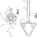
- FIG. 6is another embodiment of the insertion device of FIG. 1 incorporating a plurality of bores
- FIG. 7is a side view of the insertion device of FIG. 6 ;
- FIG. 8is a side view of an alternate embodiment of the insertion device of FIG. 1 shown in a disassembled condition with the head separated from the shaft;
- FIG. 9is a cross-sectional view of the insertion device of FIG. 8 shown in an assembled condition and after attachment to the fastening apparatus seen in FIG. 2 .
- proximalwill refer to the end of the device that is closer to the clinician
- distalwill refer to the end of the device that is further from the clinician
- fastening apparatusshould be understood to include any device configured to attach one section of tissue to another, including but not being limited to a circular surgical stapler, such as the anastomosis surgical stapling instrument disclosed in U.S. Pat. No.
- body orificeshould be understood to include any opening formed in tissue, either pre-existing or created by a practitioner.
- FIG. 1illustrates one embodiment of the presently disclosed insertion device 10 that is the subject of the present disclosure.
- Insertion device 10includes a head 12 with a shaft 14 extending proximally therefrom that is configured to releasably engage a fastening apparatus 100 ( FIG. 2 ) so as to facilitate the insertion of the fastening apparatus 100 into a patient's orifice or body cavity.
- Fastening apparatus 100includes a proximal handle assembly 102 , an elongated central body portion 104 and a distal head portion 106 .
- the length, shape and/or the diameter of the central body portion 104 and the head portion 106may be varied to suit a particular surgical procedure.
- Head portion 106includes a retaining member 108 that extends distally beyond a shell assembly 110 .
- Retaining member 108includes an annular protrusion 112 that is configured to releasably engage a corresponding structure on a fastening component (not shown), e.g. an anvil assembly, as well as on the insertion device 10 ( FIG. 1 ) that is the subject of the present disclosure, as discussed in further detail below. Further details regarding fastening apparatus 100 may be obtained through reference to U.S. Pat. No. 7,168,604, the entire contents of which are incorporated by reference herein.
- the insertion device 10and the various embodiments thereof, are described and depicted in connection with the fastening apparatus 100 of FIG. 2 , it should be understood that the insertion device 10 may be used with any number of surgical devices where it is desirable to facilitate the insertion thereof into a patient's orifice or body cavity.
- head 12 of insertion device 10includes a smooth, atraumatic leading or outer surface 16 defining a radius that is at least substantially equal to the maximum radius of the distal end of the fastening apparatus 100 ( FIG. 2 ) to which the insertion device 10 is to be attached.
- the size and configuration of head 12facilitates insertion of fastening apparatus 100 into a body orifice and substantially prevents tissue from entering the shell assembly 110 of the fastening apparatus 100 during insertion.
- Head 12has a proximal end 18 that is connected to the shaft 14 , and a substantially rounded distal end 20 . To facilitate the releasable attachment of shaft 14 to the retaining member 108 ( FIG.
- the shaft 14 of the insertion device 10includes a plurality of flexible fingers 22 and an internal shoulder 24 that is configured to releasably engage a corresponding annular protrusion 112 ( FIG. 2 ) formed on the retaining member 108 , as discussed in further detail below.
- the head 12 and the shaft 14may be formed of any suitable biocompatible material, including but not being limited to stainless steel or polymeric materials, and may be formed by various methods, e.g. injection molding.
- Head 12includes an attachment surface 26 configured to engage a removal member 28 .
- an attachment surface 26configured to engage a removal member 28 .
- each embodiment of the present disclosurewill be discussed, and depicted in the corresponding figures, as including a single attachment surface 26 and a single removal member 28 .
- the incorporation of one or more additional attachment surfaces 26 and removal members 28is also within the scope of the present disclosure.
- the attachment surface 26is configured as a throughbore 30 formed in the head 12 of device 10 .
- the attachment surface 26is configured to receive the removal member 28 such that the removal member 28 passes through the head 12 of device 10 .
- the removal membercan be in the form of a suture, wire or other flexible member insertable through the bore to enable removal.
- an insertion device 110that includes an attachment surface 126 configured as a partial recess or depression formed in head 112 such that a cross-member 130 is defined.
- removal member 28is passed beneath the cross-member 130 and is thereafter attached to the cross-member 130 in any suitable manner, e.g. the removal member 28 is tied around the cross-member 130 .
- cross-member 130preferably defines a smooth continuous surface along the exterior of head 112 to prevent snagging or tearing of tissue.
- the removal member in this embodiment as well as the other embodiments described hereincan be in the form of a suture, wire or other flexible member.
- the clinicianmay remove device 10 from the patient by grabbing or grasping removal member 28 , or any other portion of device 10 if more easily accessible.
- the present disclosurecontemplates the grasping of removal member 28 , or the device 10 , itself, through any suitable means, including but not being limited to using a grasping apparatus (not shown) or the clinician's hand.
- the removal member 28may be associated with the attachment surface 26 in any manner that facilitates the grasping thereof.
- a removal member 128is disclosed that includes a first end 132 that is connected to attachment surface 26 while a second end 134 thereof remains free.
- each of the respective first and second ends 132 , 134 of removal member 128may be connected to the attachment surface 26 , either releasably or fixedly, as discussed above.
- a removal member 228is disclosed that exhibits a substantially annular configuration, e.g. a substantially elliptical or circular configuration, that is devoid of the respective first and second ends 132 , 134 of the removal member 128 ( FIG. 4 ).
- FIGS. 6 and 7depict another embodiment of the insertion device that is the subject of the present disclosure.
- Insertion device 210performs substantially in accordance with the insertion device 10 ( FIG. 1 ) discussed above and generally includes a head 212 with a smooth, atraumatic leading outer surface 216 , and a shaft 214 that extends proximally therefrom.
- head 212has a substantially flat proximal surface 236 that is oriented so as to be substantially perpendicular to a longitudinal axis of the shaft 214 .
- Proximal surface 236includes a plurality of recesses or bores 238 that serve to reduce the weight of insertion device 210 as well as reduce any suction effects that may be created between tissue and a surgical fastening device (not shown).
- head 212includes at least one attachment surface 26 (or alternatively 126 of FIG. 3 ) that is configured to engage at least one removal member 28 , as discussed above with respect to each of the embodiments of FIGS. 1 and 3-5 .
- shaft 214 of insertion device 210includes flexible fingers 22 and an internal shoulder (not shown) such that the insertion device 210 is configured for releasable engagement with the distal end of a fastening apparatus 100 ( FIG. 2 ).
- Shaft 14generally includes a shaft barrel 32 that defines a lumen 34 extending at least partially therethrough and flexible fingers 22 .
- the lumen 34includes the internal shoulder 24 configured to releasably engage the annular protrusion 112 ( FIG. 2 ) formed on the retaining member 108 of the fastening apparatus 100 .
- the flexible fingers 22are splayed radially outward such that the retaining member may be received.
- the annular protrusion 112engages the internal shoulder 24 , thereby releasably securing the insertion device 10 to the fastening apparatus. Further details regarding the releasable engagement of the insertion device 10 with the retaining member 108 of the surgical fastening apparatus 100 may be obtained through reference to U.S. Pat. No. 7,168,604.
- the annular protrusion 112( FIG. 2 ) and the corresponding receiving structure 22 of the shaft 14 of the insertion device 10 may be any structure suitable for the intended purpose of facilitating the releasable engagement and disengagement of the insertion device 10 and the surgical fastening apparatus 100 .
- the shaft barrel 32is releasably connected to the head 12 .
- the shaft barrel 32may be connected to the head 12 in any suitable manner, including but not being limited to a threaded connection or snap-fit arrangement therebetween, such that the head 12 is interchangeable with a variety of shafts, thereby facilitating the use of device 10 with a variety of fastening apparatus 100 ( FIG. 2 ).
- the shaft barrel 32 and the head 12may be integrally formed.
- the insertion device 310includes a head 312 and a shaft 314 , and is similar to the insertion device 10 discussed above with respect to FIGS. 1-7 . Accordingly, the insertion device 310 will only be discussed with respect to its differences from the insertion device 10 .
- the head 312defines a generally conical configuration having a substantially blunt distal end 340 to facilitate atraumatic insertion.
- the distal end 340includes the aforedescribed attachment surface 326 for the reception of a removal member 328 . While the embodiment of the head 312 seen in FIGS. 8-9 depicts the attachment structure 326 as including a throughbore 330 that extends through the head 312 , alternate configurations for the attachment structure 326 are also within the scope of the present disclosure.
- the head 312further includes internal receipt structure 342 to facilitate attachment of the head 312 to the shaft 314 , and thus, assembly of the insertion device 310 .
- the shaft 314extends proximally from the head 312 and includes attachment structure 344 formed at the distal end 346 thereof that is configured and dimensioned to frictionally engage, and mechanically cooperate with, the receipt structure 342 formed in the head 312 .
- the attachment structure 344includes a plurality of first ribs 348 extending radially outward from the distal end 346 of the shaft 314 such that the distal end 346 defines a transverse dimension “D.sub.S”.
- the transverse dimension “D.sub.S”is greater than the internal transverse dimension “D.sub.H” defined by the receipt structure 342 formed in the head 312 such that an interference fit is created upon insertion of the distal end 346 of the shaft 314 into the head 312 , as seen in FIG. 9 . It is contemplated that the head 312 and shaft 314 can be permanently affixed or removed attached by the aforedescribed structure or other structure.
- the shaft 314further includes an engagement member 350 located proximally of the plurality of splines 352 formed about the shaft 314 , which mate with a plurality of corresponding grooves 114 formed in the shell assembly 116 of the fastening apparatus 100 .
- the engagement member 350includes a second rib 354 extending outwardly from the shaft 314 to define a transverse dimension “D.sub.E”.
- the transverse dimension “D.sub.E”is greater than an internal transverse dimension “D.sub.B” defined by the internal wall 118 of the shell boss 120 component of the shell assembly 116 .
- the engagement member 350frictionally engages, and mechanically cooperates with, the internal wall 118 to create an interference fit which ensures that the insertion device 310 remains attached to the fastening apparatus 100 during insertion, e.g., by preventing inadvertent displacement of the insertion apparatus 310 .
- the clinicianmanipulates the approximation knob 122 ( FIG. 2 ) of the handle assembly 102 to advance the retaining member 108 ( FIG. 2 ), and thus, the insertion device 310 , distally.
- the apparatus 100is packaged with the insertion device connected to the retaining member 108 and the instrument approximately 3 ⁇ 4 clamped (about one full turn from full approximation).
- the apparatusis ready for insertion, with the insertion device secured on the instrument, but the safety cannot be disengaged so the surgeon cannot inadvertently fire the instrument (unless the surgeon further approximates the instrument).
- the instrumentcan be unclamped (unapproximated) in the manner described above.
- attachment structure 344 and the engagement member 350 included on the shaft 314are respectively illustrated as first and second ribs 348 , 354 , in alternate embodiments, the attachment structure 344 and the engagement member 350 may be configured as any protrusion suitable for the intended purpose of creating an interference fit with the head 312 and the fastening apparatus 100 , respectively, including but not being limited to spherical bumps or the like. In one embodiment, four ribs or four bumps are provided, although a different number is also contemplated to achieve the attachment function.
- the insertion devices disclosed hereincan be reusable (re-sterilized) and made of material such as aluminum, or can be disposable (single use) made of material such as plastic.
- the shaft and headare welded together.
- the shaft and headare ultrasonically welded together.
- four ribs for providing an interference fit with the instrument retainerare provided.
- four substantially spherical bumpsare provided.
Landscapes
- Health & Medical Sciences (AREA)
- Life Sciences & Earth Sciences (AREA)
- Surgery (AREA)
- Heart & Thoracic Surgery (AREA)
- Engineering & Computer Science (AREA)
- Biomedical Technology (AREA)
- Nuclear Medicine, Radiotherapy & Molecular Imaging (AREA)
- Medical Informatics (AREA)
- Molecular Biology (AREA)
- Animal Behavior & Ethology (AREA)
- General Health & Medical Sciences (AREA)
- Public Health (AREA)
- Veterinary Medicine (AREA)
- Surgical Instruments (AREA)
Abstract
Description
Claims (13)
Priority Applications (1)
| Application Number | Priority Date | Filing Date | Title |
|---|---|---|---|
| US15/818,679US10653421B2 (en) | 2007-09-24 | 2017-11-20 | Insertion aid with interference fit |
Applications Claiming Priority (4)
| Application Number | Priority Date | Filing Date | Title |
|---|---|---|---|
| US99502507P | 2007-09-24 | 2007-09-24 | |
| US7475608P | 2008-06-23 | 2008-06-23 | |
| US12/233,824US9820748B2 (en) | 2007-09-24 | 2008-09-19 | Insertion aid with interference fit |
| US15/818,679US10653421B2 (en) | 2007-09-24 | 2017-11-20 | Insertion aid with interference fit |
Related Parent Applications (2)
| Application Number | Title | Priority Date | Filing Date |
|---|---|---|---|
| US12/233,824ContinuationUS9820748B2 (en) | 2007-09-24 | 2008-09-19 | Insertion aid with interference fit |
| US12/233,824DivisionUS9820748B2 (en) | 2007-09-24 | 2008-09-19 | Insertion aid with interference fit |
Publications (2)
| Publication Number | Publication Date |
|---|---|
| US20180070947A1 US20180070947A1 (en) | 2018-03-15 |
| US10653421B2true US10653421B2 (en) | 2020-05-19 |
Family
ID=40239533
Family Applications (2)
| Application Number | Title | Priority Date | Filing Date |
|---|---|---|---|
| US12/233,824Active2032-06-05US9820748B2 (en) | 2007-09-24 | 2008-09-19 | Insertion aid with interference fit |
| US15/818,679Expired - Fee RelatedUS10653421B2 (en) | 2007-09-24 | 2017-11-20 | Insertion aid with interference fit |
Family Applications Before (1)
| Application Number | Title | Priority Date | Filing Date |
|---|---|---|---|
| US12/233,824Active2032-06-05US9820748B2 (en) | 2007-09-24 | 2008-09-19 | Insertion aid with interference fit |
Country Status (5)
| Country | Link |
|---|---|
| US (2) | US9820748B2 (en) |
| EP (1) | EP2039303A3 (en) |
| JP (1) | JP5425435B2 (en) |
| AU (1) | AU2008221630B2 (en) |
| CA (1) | CA2639803A1 (en) |
Families Citing this family (11)
| Publication number | Priority date | Publication date | Assignee | Title |
|---|---|---|---|---|
| US9820748B2 (en) | 2007-09-24 | 2017-11-21 | Covidien Lp | Insertion aid with interference fit |
| US20120012641A1 (en)* | 2010-07-19 | 2012-01-19 | Milliman Keith L | Anvil assembly for surgical stapling device |
| ITRM20100408A1 (en)* | 2010-07-22 | 2012-01-23 | Univ Roma Tor Vergata | DISPOSABLE HEAD FOR CIRCULAR SUTURING MACHINE TO BE USED IN COLORECTAL LAPAROSCOPIC ANASTOMOSIS. |
| BR112013019631B1 (en)* | 2011-02-02 | 2022-11-01 | FILICIOTTO, Sam | SURGICAL SYSTEMS AND METHODS FOR THEM |
| JP2012221340A (en)* | 2011-04-12 | 2012-11-12 | Fujitsu Ltd | Control method, program and computer |
| US8733615B2 (en)* | 2011-05-19 | 2014-05-27 | Ethicon Endo-Surgery, Inc. | Circular stapler with frictional reducing member |
| US10039546B2 (en) | 2013-12-23 | 2018-08-07 | Covidien Lp | Loading unit including shipping member |
| US9579099B2 (en) | 2014-01-07 | 2017-02-28 | Covidien Lp | Shipping member for loading unit |
| US9867619B2 (en)* | 2014-06-24 | 2018-01-16 | Covidien Lp | System for delivering an anvil assembly to a surgical site |
| US9730694B2 (en) | 2014-07-01 | 2017-08-15 | Covidien Lp | Loading unit including shipping assembly |
| US10881408B2 (en)* | 2015-04-22 | 2021-01-05 | Covidien Lp | Interlock assembly for replaceable loading units |
Citations (31)
| Publication number | Priority date | Publication date | Assignee | Title |
|---|---|---|---|---|
| US4505272A (en) | 1982-02-23 | 1985-03-19 | Vsesojozny Naucho-Issledovatelsky i Ispytatelny Institut Meditsinskoi Tekhniki | Surgical suturing instrument for performing anastomoses between structures of the digestive tract |
| US4817847A (en) | 1986-04-21 | 1989-04-04 | Finanzaktiengesellschaft Globe Control | Instrument and a procedure for performing an anastomosis |
| US4848367A (en) | 1987-02-11 | 1989-07-18 | Odis L. Avant | Method of effecting dorsal vein ligation |
| US4873977A (en) | 1987-02-11 | 1989-10-17 | Odis L. Avant | Stapling method and apparatus for vesicle-urethral re-anastomosis following retropubic prostatectomy and other tubular anastomosis |
| US5047039A (en) | 1990-09-14 | 1991-09-10 | Odis Lynn Avant | Method and apparatus for effecting dorsal vein ligation and tubular anastomosis and laparoscopic prostatectomy |
| USD331971S (en) | 1990-09-14 | 1992-12-22 | Ethicon, Inc. | Anvil for intraluminal anastomotic surgical stapler |
| US5197648A (en) | 1988-11-29 | 1993-03-30 | Gingold Bruce S | Surgical stapling apparatus |
| US5275322A (en) | 1991-08-23 | 1994-01-04 | Ethicon, Inc. | Surgical anastomosis stapling instrument |
| US5314435A (en) | 1992-05-19 | 1994-05-24 | United States Surgical Corporation | Anvil delivery system |
| US5443198A (en) | 1991-10-18 | 1995-08-22 | United States Surgical Corporation | Surgical fastener applying apparatus |
| US5445644A (en)* | 1992-04-16 | 1995-08-29 | Ethicon, Inc. | Pyloroplasty/pylorectomy shield |
| US5464415A (en) | 1994-03-15 | 1995-11-07 | Chen; Te-Chuan | Sutureless intestinal anastomosis gun |
| US5522534A (en) | 1993-10-01 | 1996-06-04 | United States Surgical Corporation | Anvil for surgical stapler |
| US5531785A (en) | 1994-05-06 | 1996-07-02 | Autogenics, Inc. | Prosthetic heart valve holder |
| US5669918A (en) | 1995-03-16 | 1997-09-23 | Deutsche Forschungsanstalt Fur Luft-Und Raumfahrt E.V. | Surgical instrument for preparing an anastomosis in minimally invasive surgery |
| EP0803229A1 (en) | 1996-04-22 | 1997-10-29 | United States Surgical Corporation | Insertion device for surgical apparatus |
| US5718360A (en)* | 1992-09-08 | 1998-02-17 | United States Surgical Corporation | Surgical apparatus and detachable anvil rod therefor |
| US5860581A (en)* | 1994-03-24 | 1999-01-19 | United States Surgical Corporation | Anvil for circular stapler |
| US6050472A (en) | 1996-04-26 | 2000-04-18 | Olympus Optical Co., Ltd. | Surgical anastomosis stapler |
| US6083241A (en) | 1998-11-23 | 2000-07-04 | Ethicon Endo-Surgery, Inc. | Method of use of a circular stapler for hemorrhoidal procedure |
| US6102271A (en) | 1998-11-23 | 2000-08-15 | Ethicon Endo-Surgery, Inc. | Circular stapler for hemorrhoidal surgery |
| US6258107B1 (en) | 1998-08-17 | 2001-07-10 | DEUTSCHES ZENTRUM FüR LUFT-UND RAUMFAHRT E.V. | Apparatus for connecting a variety of surgical instruments to an operating control device |
| US6338737B1 (en)* | 1997-07-17 | 2002-01-15 | Haviv Toledano | Flexible annular stapler for closed surgery of hollow organs |
| US20040225277A1 (en)* | 2003-03-11 | 2004-11-11 | Jacob Brian P. | Endoluminal colostomy system and procedure |
| US7182239B1 (en)* | 2004-08-27 | 2007-02-27 | Myers Stephan R | Segmented introducer device for a circular surgical stapler |
| US20090250502A1 (en) | 2003-10-17 | 2009-10-08 | Tyco Healthcare Group Lp | Surgical stapling device |
| US7901416B2 (en) | 2001-03-05 | 2011-03-08 | Tyco Healthcare Group, L.P. | Apparatus and method for performing a bypass procedure in a digestive system |
| US7976495B2 (en) | 2005-08-31 | 2011-07-12 | Cook Medical Technologies Llc | Peg tube with wireless pull tip |
| US8006701B2 (en) | 2004-11-05 | 2011-08-30 | Ethicon Endo-Surgery, Inc. | Device and method for the therapy of obesity |
| US8353438B2 (en)* | 2009-11-19 | 2013-01-15 | Ethicon Endo-Surgery, Inc. | Circular stapler introducer with rigid cap assembly configured for easy removal |
| US9820748B2 (en) | 2007-09-24 | 2017-11-21 | Covidien Lp | Insertion aid with interference fit |
Family Cites Families (8)
| Publication number | Priority date | Publication date | Assignee | Title |
|---|---|---|---|---|
| US5119983A (en) | 1987-05-26 | 1992-06-09 | United States Surgical Corporation | Surgical stapler apparatus |
| US5005749A (en) | 1988-07-01 | 1991-04-09 | United States Surgical Corp. | Anastomosis surgical stapling instrument |
| US5376098A (en) | 1992-10-09 | 1994-12-27 | United States Surgical Corporation | Fragmentable anastomosis ring applier |
| US5404870A (en) | 1993-05-28 | 1995-04-11 | Ethicon, Inc. | Method of using a transanal inserter |
| CA2444372C (en)* | 2001-04-13 | 2009-12-22 | Paul G. Alchas | Intradermal needle |
| JP2003310453A (en)* | 2002-04-25 | 2003-11-05 | Sanyo Electric Co Ltd | Cooking device |
| JP4422027B2 (en) | 2002-10-04 | 2010-02-24 | タイコ ヘルスケア グループ エルピー | Surgical stapling device |
| EP1635712B1 (en) | 2003-06-20 | 2015-09-30 | Covidien LP | Surgical stapling device |
- 2008
- 2008-09-19USUS12/233,824patent/US9820748B2/enactiveActive
- 2008-09-22JPJP2008243420Apatent/JP5425435B2/ennot_activeExpired - Fee Related
- 2008-09-23CACA002639803Apatent/CA2639803A1/ennot_activeAbandoned
- 2008-09-23AUAU2008221630Apatent/AU2008221630B2/ennot_activeCeased
- 2008-09-23EPEP08253106Apatent/EP2039303A3/ennot_activeWithdrawn
- 2017
- 2017-11-20USUS15/818,679patent/US10653421B2/ennot_activeExpired - Fee Related
Patent Citations (33)
| Publication number | Priority date | Publication date | Assignee | Title |
|---|---|---|---|---|
| US4505272A (en) | 1982-02-23 | 1985-03-19 | Vsesojozny Naucho-Issledovatelsky i Ispytatelny Institut Meditsinskoi Tekhniki | Surgical suturing instrument for performing anastomoses between structures of the digestive tract |
| US4817847A (en) | 1986-04-21 | 1989-04-04 | Finanzaktiengesellschaft Globe Control | Instrument and a procedure for performing an anastomosis |
| US4848367A (en) | 1987-02-11 | 1989-07-18 | Odis L. Avant | Method of effecting dorsal vein ligation |
| US4873977A (en) | 1987-02-11 | 1989-10-17 | Odis L. Avant | Stapling method and apparatus for vesicle-urethral re-anastomosis following retropubic prostatectomy and other tubular anastomosis |
| US5197648A (en) | 1988-11-29 | 1993-03-30 | Gingold Bruce S | Surgical stapling apparatus |
| US5047039A (en) | 1990-09-14 | 1991-09-10 | Odis Lynn Avant | Method and apparatus for effecting dorsal vein ligation and tubular anastomosis and laparoscopic prostatectomy |
| USD331971S (en) | 1990-09-14 | 1992-12-22 | Ethicon, Inc. | Anvil for intraluminal anastomotic surgical stapler |
| US5275322A (en) | 1991-08-23 | 1994-01-04 | Ethicon, Inc. | Surgical anastomosis stapling instrument |
| US5443198A (en) | 1991-10-18 | 1995-08-22 | United States Surgical Corporation | Surgical fastener applying apparatus |
| US5445644A (en)* | 1992-04-16 | 1995-08-29 | Ethicon, Inc. | Pyloroplasty/pylorectomy shield |
| US5314435A (en) | 1992-05-19 | 1994-05-24 | United States Surgical Corporation | Anvil delivery system |
| US5718360A (en)* | 1992-09-08 | 1998-02-17 | United States Surgical Corporation | Surgical apparatus and detachable anvil rod therefor |
| US5522534A (en) | 1993-10-01 | 1996-06-04 | United States Surgical Corporation | Anvil for surgical stapler |
| US5464415A (en) | 1994-03-15 | 1995-11-07 | Chen; Te-Chuan | Sutureless intestinal anastomosis gun |
| US5860581A (en)* | 1994-03-24 | 1999-01-19 | United States Surgical Corporation | Anvil for circular stapler |
| US5531785A (en) | 1994-05-06 | 1996-07-02 | Autogenics, Inc. | Prosthetic heart valve holder |
| US5669918A (en) | 1995-03-16 | 1997-09-23 | Deutsche Forschungsanstalt Fur Luft-Und Raumfahrt E.V. | Surgical instrument for preparing an anastomosis in minimally invasive surgery |
| EP0803229A1 (en) | 1996-04-22 | 1997-10-29 | United States Surgical Corporation | Insertion device for surgical apparatus |
| US5836503A (en) | 1996-04-22 | 1998-11-17 | United States Surgical Corporation | Insertion device for surgical apparatus |
| US6050472A (en) | 1996-04-26 | 2000-04-18 | Olympus Optical Co., Ltd. | Surgical anastomosis stapler |
| US6338737B1 (en)* | 1997-07-17 | 2002-01-15 | Haviv Toledano | Flexible annular stapler for closed surgery of hollow organs |
| US6258107B1 (en) | 1998-08-17 | 2001-07-10 | DEUTSCHES ZENTRUM FüR LUFT-UND RAUMFAHRT E.V. | Apparatus for connecting a variety of surgical instruments to an operating control device |
| US6102271A (en) | 1998-11-23 | 2000-08-15 | Ethicon Endo-Surgery, Inc. | Circular stapler for hemorrhoidal surgery |
| US6083241A (en) | 1998-11-23 | 2000-07-04 | Ethicon Endo-Surgery, Inc. | Method of use of a circular stapler for hemorrhoidal procedure |
| US8317809B2 (en)* | 2000-03-06 | 2012-11-27 | Covidien Lp | Apparatus and method for performing a bypass procedure in a digestive system |
| US7901416B2 (en) | 2001-03-05 | 2011-03-08 | Tyco Healthcare Group, L.P. | Apparatus and method for performing a bypass procedure in a digestive system |
| US20040225277A1 (en)* | 2003-03-11 | 2004-11-11 | Jacob Brian P. | Endoluminal colostomy system and procedure |
| US20090250502A1 (en) | 2003-10-17 | 2009-10-08 | Tyco Healthcare Group Lp | Surgical stapling device |
| US7182239B1 (en)* | 2004-08-27 | 2007-02-27 | Myers Stephan R | Segmented introducer device for a circular surgical stapler |
| US8006701B2 (en) | 2004-11-05 | 2011-08-30 | Ethicon Endo-Surgery, Inc. | Device and method for the therapy of obesity |
| US7976495B2 (en) | 2005-08-31 | 2011-07-12 | Cook Medical Technologies Llc | Peg tube with wireless pull tip |
| US9820748B2 (en) | 2007-09-24 | 2017-11-21 | Covidien Lp | Insertion aid with interference fit |
| US8353438B2 (en)* | 2009-11-19 | 2013-01-15 | Ethicon Endo-Surgery, Inc. | Circular stapler introducer with rigid cap assembly configured for easy removal |
Non-Patent Citations (1)
| Title |
|---|
| European Office Action dated Oct. 17, 2017, issued in EP Appln. No. 08253106. |
Also Published As
| Publication number | Publication date |
|---|---|
| AU2008221630B2 (en) | 2013-11-28 |
| EP2039303A2 (en) | 2009-03-25 |
| JP2009136670A (en) | 2009-06-25 |
| US20090082777A1 (en) | 2009-03-26 |
| JP5425435B2 (en) | 2014-02-26 |
| AU2008221630A1 (en) | 2009-04-09 |
| US9820748B2 (en) | 2017-11-21 |
| CA2639803A1 (en) | 2009-03-24 |
| EP2039303A3 (en) | 2009-12-23 |
| US20180070947A1 (en) | 2018-03-15 |
Similar Documents
| Publication | Publication Date | Title |
|---|---|---|
| US10653421B2 (en) | Insertion aid with interference fit | |
| US10952767B2 (en) | Connector clip for securing an introducer to a surgical fastener applying apparatus | |
| JP5543092B2 (en) | Accessories for anvil delivery device | |
| US5718360A (en) | Surgical apparatus and detachable anvil rod therefor | |
| US5836503A (en) | Insertion device for surgical apparatus | |
| US8267301B2 (en) | Surgical stapler | |
| US8795308B2 (en) | Laparoscopic gastric and intestinal trocar | |
| JP4550946B2 (en) | Transanal anastomosis ring insertion device | |
| JP2013154163A (en) | Circular stapler including buttress | |
| US8845662B2 (en) | Vascular anastomosis device | |
| US20170360443A1 (en) | Damage resistant anvil assembly | |
| US11627967B2 (en) | Trans-anastomotic insertion device | |
| US20050277962A1 (en) | Introducer device and method for delivering a medical instrument to a target in vivo site | |
| EP1790295A1 (en) | Removable introducer device for delivering a medical instrument to a target in vivo site | |
| CN210697721U (en) | Puncture Rod and Puncture Rod Assembly | |
| US20160192937A1 (en) | Adaptor with flexible tip coupled to a wire needle for a circular stapler ogival trocar | |
| US20050165438A1 (en) | Device and method for introducing surgical instruments into the body |
Legal Events
| Date | Code | Title | Description |
|---|---|---|---|
| AS | Assignment | Owner name:TYCO HEALTHCARE GROUP LP, MASSACHUSETTS Free format text:ASSIGNMENT OF ASSIGNORS INTEREST;ASSIGNORS:MILLIMAN, KEITH L.;WENCHELL, THOMAS;ROY, PHILIP C.;SIGNING DATES FROM 20080917 TO 20081001;REEL/FRAME:044183/0318 Owner name:COVIDIEN LP, MASSACHUSETTS Free format text:CHANGE OF NAME;ASSIGNOR:TYCO HEALTHCARE GROUP LP;REEL/FRAME:044798/0596 Effective date:20120928 | |
| FEPP | Fee payment procedure | Free format text:ENTITY STATUS SET TO UNDISCOUNTED (ORIGINAL EVENT CODE: BIG.); ENTITY STATUS OF PATENT OWNER: LARGE ENTITY | |
| STPP | Information on status: patent application and granting procedure in general | Free format text:DOCKETED NEW CASE - READY FOR EXAMINATION | |
| STPP | Information on status: patent application and granting procedure in general | Free format text:NON FINAL ACTION MAILED | |
| STPP | Information on status: patent application and granting procedure in general | Free format text:RESPONSE TO NON-FINAL OFFICE ACTION ENTERED AND FORWARDED TO EXAMINER | |
| STPP | Information on status: patent application and granting procedure in general | Free format text:NOTICE OF ALLOWANCE MAILED -- APPLICATION RECEIVED IN OFFICE OF PUBLICATIONS | |
| ZAAA | Notice of allowance and fees due | Free format text:ORIGINAL CODE: NOA | |
| ZAAB | Notice of allowance mailed | Free format text:ORIGINAL CODE: MN/=. | |
| STPP | Information on status: patent application and granting procedure in general | Free format text:PUBLICATIONS -- ISSUE FEE PAYMENT VERIFIED | |
| STCF | Information on status: patent grant | Free format text:PATENTED CASE | |
| FEPP | Fee payment procedure | Free format text:MAINTENANCE FEE REMINDER MAILED (ORIGINAL EVENT CODE: REM.); ENTITY STATUS OF PATENT OWNER: LARGE ENTITY | |
| LAPS | Lapse for failure to pay maintenance fees | Free format text:PATENT EXPIRED FOR FAILURE TO PAY MAINTENANCE FEES (ORIGINAL EVENT CODE: EXP.); ENTITY STATUS OF PATENT OWNER: LARGE ENTITY | |
| STCH | Information on status: patent discontinuation | Free format text:PATENT EXPIRED DUE TO NONPAYMENT OF MAINTENANCE FEES UNDER 37 CFR 1.362 | |
| FP | Lapsed due to failure to pay maintenance fee | Effective date:20240519 |