US10653052B2 - Wheel track renovator and method of use - Google Patents
Wheel track renovator and method of useDownload PDFInfo
- Publication number
- US10653052B2 US10653052B2US15/559,006US201615559006AUS10653052B2US 10653052 B2US10653052 B2US 10653052B2US 201615559006 AUS201615559006 AUS 201615559006AUS 10653052 B2US10653052 B2US 10653052B2
- Authority
- US
- United States
- Prior art keywords
- track
- auger
- screws
- renovator
- wheel
- Prior art date
- Legal status (The legal status is an assumption and is not a legal conclusion. Google has not performed a legal analysis and makes no representation as to the accuracy of the status listed.)
- Active
Links
- 238000000034methodMethods0.000titleclaimsdescription7
- 239000002689soilSubstances0.000claimsdescription38
- 238000012856packingMethods0.000claimsdescription19
- 238000009499grossingMethods0.000claimsdescription11
- 238000009313farmingMethods0.000description5
- 239000000428dustSubstances0.000description1
- 238000005188flotationMethods0.000description1
- 238000012986modificationMethods0.000description1
- 230000004048modificationEffects0.000description1
- 239000011435rockSubstances0.000description1
Images


Classifications
- A—HUMAN NECESSITIES
- A01—AGRICULTURE; FORESTRY; ANIMAL HUSBANDRY; HUNTING; TRAPPING; FISHING
- A01B—SOIL WORKING IN AGRICULTURE OR FORESTRY; PARTS, DETAILS, OR ACCESSORIES OF AGRICULTURAL MACHINES OR IMPLEMENTS, IN GENERAL
- A01B37/00—Devices for loosening soil compacted by wheels or the like
- A—HUMAN NECESSITIES
- A01—AGRICULTURE; FORESTRY; ANIMAL HUSBANDRY; HUNTING; TRAPPING; FISHING
- A01B—SOIL WORKING IN AGRICULTURE OR FORESTRY; PARTS, DETAILS, OR ACCESSORIES OF AGRICULTURAL MACHINES OR IMPLEMENTS, IN GENERAL
- A01B35/00—Other machines for working soil not specially adapted for working soil on which crops are growing
- A01B35/20—Tools; Details
- A01B35/28—Rotating tools; Mounting rotating tools
- E—FIXED CONSTRUCTIONS
- E02—HYDRAULIC ENGINEERING; FOUNDATIONS; SOIL SHIFTING
- E02F—DREDGING; SOIL-SHIFTING
- E02F5/00—Dredgers or soil-shifting machines for special purposes
- E02F5/02—Dredgers or soil-shifting machines for special purposes for digging trenches or ditches
- E02F5/12—Dredgers or soil-shifting machines for special purposes for digging trenches or ditches with equipment for back-filling trenches or ditches
Definitions
- This inventionrelates to a wheel track renovator and associated method of use.
- the inventionrelates to the filling in of agricultural traffic lanes created by controlled traffic farming.
- the wheel track renovatormay be used for other purposes such as smoothing ruts in dirt roads.
- Controlled traffic farmingis a management tool which is used to reduce the damage to soil caused when heavy or repeated agricultural machinery passes on the land.
- Controlled traffic farmingis a system which confines all machinery loads to the least possible area through the use of permanent tracks.
- a wheel track renovatorcomprising:
- the bodytypically includes a frame to which are mounted the one or more augers.
- the bodyusually includes a pair of packing wheels.
- the packing wheelsare typically located behind the frame.
- the packing wheelsmay have tyres.
- the tyresmay include a tread.
- the bodymay also include a first pair of support wheels.
- the first pair of support wheelsmay be located in front of the frame.
- the bodymay include a second pair of support wheels.
- the second set of support wheelsmay be located behind the first pair of support wheels.
- the support wheelsmay be fixed in position with respect to the frame.
- the support wheelsmay be pivotally mounted to the frame.
- the framemay be towed behind a vehicle.
- the framemay be connected to the vehicle via a three point linkage.
- Each augertypically has at least one screw. However, normally there are at least two screws on each auger.
- each augeris angled perpendicularly with the direction of travel. However, it should be appreciated that each auger may inclined with respect to the direction of travel. For example, an auger may be included at 30, 45 or 60 degrees with respect to the direction of travel.
- the augermay have one screw, two screws, fours screws, six screws or eight screws on each auger.
- a spaceis normally located between each pair of screws.
- a first screwmay be a counter-clockwise screw whilst a second screw may be a clockwise screw. That is, when the screws are rotated, they rotate toward the space.
- Each augernormally has two screws. That is, there are two pairs of screws with two associated spaces, each space located between each pair of screws.
- each augermay have two screws.
- the one or more augerstypically rotate in reverse compared to the direction of travel of the body.
- the driveis in the form of a motor.
- the motoris in the form of a hydraulic drive.
- the hydraulic drivemay be powered from a hydraulic system of an agricultural vehicle such as a tractor.
- the motormay be powered via a power take off from an agricultural vehicle such as a tractor.
- a smoothing devicemay be located between two screws of the soil movement device.
- the smoothing devicemay be in the form of a series of paddles that extend outwardly from a shaft of the auger at the space between a pair of screws.
- the smoothing devicemay be in the form a series of bars. The bars may extend between two screws over the space between the augers.
- a prickle chainmay be attached to and located behind the body.
- the inventionresides in a method of filling in tracks, the method including the step of:
- the methodmay further include the step of moving soil from both sides of a track into the track using one or more mechanically rotated augers.
- the one or more augershave two screws which move the soil toward the track.
- FIG. 1is a perspective view of a wheel track renovator according to a first embodiment of the invention
- FIG. 2is a side view of a wheel track renovator according to a first embodiment of the invention
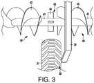
- FIG. 3is a top view of a wheel track renovator according to a first embodiment of the invention.
- FIG. 4is a perspective view of the drive mechanism according to a first embodiment of the invention.
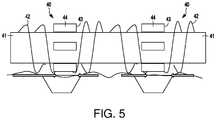
- FIG. 5is a schematic view of the operation of the augers according to a first embodiment of the invention.
- FIG. 6is a perspective view of the drive mechanism according to a an second embodiment of the invention.
- FIG. 7is a perspective view of the drive mechanism according to a second embodiment of the invention.
- FIGS. 1 and 2show a wheel track renovator 10 that is used to fill in tracks that are caused by controlled traffic farming.
- the wheel track renovator 10is towed behind a tractor 5 .
- the wheel track renovatorincludes a body 20 , a pair of packer wheels 30 , a pair of augers 40 and a drive mechanism 50 .
- the body 20is formed from a frame 21 .
- the frameincludes a central member 22 from which extend a pair of fixed support wheel mounting arms 23 and a pair of fixed packing wheel arms 24 .
- the support wheel mounting arms 23are located adjacent the ends of the central member 22 and extend outwardly from the central member 22 .
- the support wheel mounting arms 23are used to mount support wheels 25 .
- the support wheels 25 and the support wheel mounting armsform a support assembly 26 .
- the packing wheel arms 24extend rearwardly from the central member 22 .
- the packing wheel arms 24are used to mount the packing wheels 30 .
- the packing wheels 30include large flotation tyres 31 that both compress the track and provide stability.
- Three auger mounting arms 27extend outwardly from the central member 22 to rotatably mount the pair of augers 40 .
- Each auger 40is constructed from a central shaft 41 which is used to mount two separate helical screws 42 .
- the first screwis a counter-clockwise screw whilst the second screw is a clockwise screw.
- Removable wear plates(not shown) are attached to the screws 42 and can be replaced as required.
- the two screws 42 on each auger 40are spaced from each other on the shaft 41 to form a space 43 as shown in FIG. 3 .
- a series of paddles 44are located in the space. The paddles extend outwardly from the shaft 41 and are equally circumferentially spaced around the shaft 41 .
- a series of shields 50are located behind the augers 40 to prevent dust, rocks and other debris from being flicked onto the tractor. It would be appreciated that shields 50 are often placed in front of the augers also to prevent access to the augers during operation for safety.
- the shields 50are mounted to the central member 22 of the frame 21 and extend downwardly adjacent the augers 40 .
- the drive mechanism 60includes a hydraulic motor 61 which is located on the central beam of the frame 21 .
- the hydraulic motor 61is attached to the shaft 41 of the auger via a chain 62 as shown in FIG. 4 .
- the chain 62passes through an oil bath (not shown).
- the hydraulic motor 61is connected to the hydraulic system of the tractor 5 as shown in FIG. 1 .
- the hydraulic motor 61rotates the augers via the chain 62 in a direction that is opposite to the direction travel of the tractor 5 .
- the auger 40typically rotates at between 130 rpm to 200 rpm depending on soil conditions.
- the tractor 5is driven down a track that is to be filled with soil.
- the support wheels 25are located outside the track and are positioned at the desired level of the soil. It should be noted that the middle of the track is lower that the desired level of the soil whilst the soil adjacent the track is higher than the desired level of the soil.
- the hydraulic motor 61is started and causes rotation of the augers 40 in a direction that is reverse the direction of travel.
- Each auger 40contacts the soil that is located about the track and above the desired soil level and causes soil on both sides of a track to be moved in toward the centre of the auger 40 as shown in FIG. 5 .
- the soilthen moves into the space 43 between the screws 42 and falls into the track.
- the paddles 44then smooth the soil longitudinally.
- the packing wheels 30then compress the soil located within the track.
- the correct speed of the tractor 5can be judged to be appropriate by the amount soil that is being thrown against the shields 50 . If a large amount of soil is being thrown against the shields 50 which is visible to an operator, then the tractor 50 is being driven too slowly and the speed of the tractor should be increased. Alternatively, if a large amount of soil is being thrown against the shields 50 , the rotational speed of the auger can be reduced whilst maintain the speed of the tractor 50 .
- FIGS. 6 and 7show a second embodiment of the invention.
- the second embodiment of the inventionis similar to the first invention.
- the augers 40are located in the same position and driven in the same manner. Accordingly, like numerals are used to describe like components.
- the frame 21 of the body 20is pivotally mounted to two casings 70 which are used to mount two sets of support wheels 71 .
- the two casings 70are pivotally mounted to respective ends of the central member 22 .
- the two support wheels 71 on each casingare in a fixed spaced relationship to each other.
- the casing 70 with support wheels 71are positioned outside the track on the desired soil level.
- the packing wheels 30move up and down when following the contour of the filled track. If the packing wheels 30 move up due to overfilling of the tracks, this causes the frame 21 to move upwardly and pivot causing the augers 40 to reduce the amount of soil that the augers 40 shave from the ground on the sides of the tracks. Similarly, if the packing wheels 30 move down due to under-filling of the tracks, this causes the frame 21 to move downwardly and pivot causing the augers 40 to increase the amount of soil that the augers 40 shave from the ground on the sides of the tracks.
- the frame 21may include a top linkage (not shown) which is operatively attached to a draft control (not shown) of the tractor 5 . If the packing wheels 5 rise, this causes the frame 21 to pivot causing the draft control to override lift cylinders (not shown) of the tractor 5 to raise the frame 21 . This reduces the amount of soil that the augers 40 shave reducing overfilling of the tracks. Similarly, if the packing wheels 5 drop, this causes the frame 21 to pivot causing the draft control to override lift cylinders (not shown) of the tractor 5 to lower the frame 21 . This increases the amount of soil that the augers 40 shave reducing under-filling of the tracks.
- the wheel track renovatorcan be configured, for example using hydraulics, so the body can be tilted in order to allow the wheel track renovator to operate in various conditions such as on a cambered road.
Landscapes
- Life Sciences & Earth Sciences (AREA)
- Engineering & Computer Science (AREA)
- Mechanical Engineering (AREA)
- Soil Sciences (AREA)
- Environmental Sciences (AREA)
- Soil Working Implements (AREA)
Abstract
Description
- a body attachable to a vehicle;
- one or more augers mounted to the body; and
- at least one drive connected to the one or more augers to drive the one or more augers.
- moving the soil from one side of a track into the track using one or more mechanically rotated augers.
Claims (14)
Applications Claiming Priority (3)
| Application Number | Priority Date | Filing Date | Title |
|---|---|---|---|
| AU2015900935 | 2015-03-16 | ||
| AU2015900935AAU2015900935A0 (en) | 2015-03-16 | Wheel track renovator and method of use | |
| PCT/AU2016/050187WO2016145490A1 (en) | 2015-03-16 | 2016-03-16 | Wheel track renovator and method of use |
Publications (2)
| Publication Number | Publication Date |
|---|---|
| US20180092284A1 US20180092284A1 (en) | 2018-04-05 |
| US10653052B2true US10653052B2 (en) | 2020-05-19 |
Family
ID=56918165
Family Applications (1)
| Application Number | Title | Priority Date | Filing Date |
|---|---|---|---|
| US15/559,006ActiveUS10653052B2 (en) | 2015-03-16 | 2016-03-16 | Wheel track renovator and method of use |
Country Status (4)
| Country | Link |
|---|---|
| US (1) | US10653052B2 (en) |
| AU (1) | AU2016232989B2 (en) |
| CA (1) | CA2979955A1 (en) |
| WO (1) | WO2016145490A1 (en) |
Families Citing this family (3)
| Publication number | Priority date | Publication date | Assignee | Title |
|---|---|---|---|---|
| CN108100080B (en)* | 2017-12-30 | 2020-04-24 | 黄继成 | All-terrain riding type mountain land working machine |
| CN111567160B (en)* | 2020-06-08 | 2021-06-25 | 农业农村部南京农业机械化研究所 | Wheel track processing mechanism for tilling and sowing machinery |
| CN113303042B (en)* | 2021-04-15 | 2023-04-04 | 农业农村部南京农业机械化研究所 | Rut earthing device for agricultural machinery |
Citations (29)
| Publication number | Priority date | Publication date | Assignee | Title |
|---|---|---|---|---|
| US3375878A (en)* | 1965-06-30 | 1968-04-02 | Arrow Mfg Company | Tractor auger-type backfiller |
| US3876013A (en)* | 1969-12-10 | 1975-04-08 | Charles William Dunn | Self-leveling rotary screw grader |
| US3934363A (en)* | 1974-08-30 | 1976-01-27 | Mcmurray Russell L | Trench back filling and compacting apparatus |
| US3999314A (en)* | 1975-11-05 | 1976-12-28 | Miller Formless Co., Inc. | Small sub-grader |
| US4073245A (en)* | 1976-05-13 | 1978-02-14 | Everett Anderson | Levee forming apparatus and method |
| US4678365A (en)* | 1986-01-24 | 1987-07-07 | Tricon Industries | Material spreader |
| WO1988000002A1 (en) | 1986-06-27 | 1988-01-14 | Laurence Colin Phillips | Prickle chain |
| US4778305A (en)* | 1987-03-27 | 1988-10-18 | Rexworks Inc. | Slip-form paver with laterally moveable paving tool |
| US4912862A (en)* | 1989-01-09 | 1990-04-03 | Bishop William B | Backfill machine |
| US4948292A (en)* | 1989-07-24 | 1990-08-14 | Cedarapids, Inc. | Paving machine having transversely and longitudinally adjustable grade sensors |
| US5073063A (en)* | 1990-08-20 | 1991-12-17 | White Consolidated Industries, Inc. | Windrow paving machine and method of paving |
| US5353529A (en)* | 1991-12-23 | 1994-10-11 | Mccullough Charles E | Apparatus for backfilling |
| US5405214A (en)* | 1993-08-12 | 1995-04-11 | Astec Industries, Inc. | Paving machine incorporating automatic feeder control gates |
| US5479728A (en)* | 1994-03-08 | 1996-01-02 | The Charles Machine Works, Inc. | Apparatus for backfilling and tamping a trench |
| US5529434A (en)* | 1993-04-08 | 1996-06-25 | Swisher, Jr.; George W. | Paving material machine having hopper capacity and compensating tunnel capacity |
| US5531542A (en)* | 1994-11-14 | 1996-07-02 | Ingersoll-Rand Company | Dual auger/conveyor drive for a paver |
| US5533829A (en)* | 1994-09-29 | 1996-07-09 | Astec Industries, Inc. | Paving machine with mixing device and discharge conveyor assembly for remixing segregated paving materials |
| US5586731A (en)* | 1992-07-21 | 1996-12-24 | Frontier Manufacturing Company | Compost mixing and aerating apparatus |
| US5845717A (en)* | 1996-12-26 | 1998-12-08 | Gillespie; Daniel | Tractor-mounted wheel track closing device |
| US5857804A (en) | 1996-08-20 | 1999-01-12 | Cedarapids, Inc. | Asphalt paver having auger extensions for extended screeds |
| US5980153A (en)* | 1998-07-30 | 1999-11-09 | Akzo Nobel Asphalt Applications, Inc. | Telescoping auger shaft and method of manufacture |
| US6086287A (en)* | 1995-09-22 | 2000-07-11 | Sharpe; John Russell | Method and apparatus for laying roadway materials |
| US6434861B1 (en)* | 1999-11-03 | 2002-08-20 | Mccullough Charles E. | Apparatus for backfilling |
| US6582152B2 (en)* | 2000-05-11 | 2003-06-24 | Leone Construction Company | Zero clearance variable width concrete paving machine |
| US6820358B1 (en)* | 2002-01-14 | 2004-11-23 | Louie Huelsewiesche | Compact vehicle for composting manure storage under high-rise avian houses |
| WO2007126890B1 (en) | 2006-03-27 | 2008-01-03 | Charles Machine Works | Auger for use with trenching assembly |
| US7484911B2 (en)* | 2006-08-08 | 2009-02-03 | Caterpillar Inc. | Paving process and machine with feed forward material feed control system |
| US8256986B2 (en)* | 2007-11-05 | 2012-09-04 | B.V.B.A. Consulting Casters | Machine for paving concrete paths |
| US9551115B2 (en)* | 2014-12-19 | 2017-01-24 | Wirtgen Gmbh | Transition on the fly |
- 2016
- 2016-03-16USUS15/559,006patent/US10653052B2/enactiveActive
- 2016-03-16CACA2979955Apatent/CA2979955A1/enactivePending
- 2016-03-16WOPCT/AU2016/050187patent/WO2016145490A1/ennot_activeCeased
- 2016-03-16AUAU2016232989Apatent/AU2016232989B2/enactiveActive
Patent Citations (29)
| Publication number | Priority date | Publication date | Assignee | Title |
|---|---|---|---|---|
| US3375878A (en)* | 1965-06-30 | 1968-04-02 | Arrow Mfg Company | Tractor auger-type backfiller |
| US3876013A (en)* | 1969-12-10 | 1975-04-08 | Charles William Dunn | Self-leveling rotary screw grader |
| US3934363A (en)* | 1974-08-30 | 1976-01-27 | Mcmurray Russell L | Trench back filling and compacting apparatus |
| US3999314A (en)* | 1975-11-05 | 1976-12-28 | Miller Formless Co., Inc. | Small sub-grader |
| US4073245A (en)* | 1976-05-13 | 1978-02-14 | Everett Anderson | Levee forming apparatus and method |
| US4678365A (en)* | 1986-01-24 | 1987-07-07 | Tricon Industries | Material spreader |
| WO1988000002A1 (en) | 1986-06-27 | 1988-01-14 | Laurence Colin Phillips | Prickle chain |
| US4778305A (en)* | 1987-03-27 | 1988-10-18 | Rexworks Inc. | Slip-form paver with laterally moveable paving tool |
| US4912862A (en)* | 1989-01-09 | 1990-04-03 | Bishop William B | Backfill machine |
| US4948292A (en)* | 1989-07-24 | 1990-08-14 | Cedarapids, Inc. | Paving machine having transversely and longitudinally adjustable grade sensors |
| US5073063A (en)* | 1990-08-20 | 1991-12-17 | White Consolidated Industries, Inc. | Windrow paving machine and method of paving |
| US5353529A (en)* | 1991-12-23 | 1994-10-11 | Mccullough Charles E | Apparatus for backfilling |
| US5586731A (en)* | 1992-07-21 | 1996-12-24 | Frontier Manufacturing Company | Compost mixing and aerating apparatus |
| US5529434A (en)* | 1993-04-08 | 1996-06-25 | Swisher, Jr.; George W. | Paving material machine having hopper capacity and compensating tunnel capacity |
| US5405214A (en)* | 1993-08-12 | 1995-04-11 | Astec Industries, Inc. | Paving machine incorporating automatic feeder control gates |
| US5479728A (en)* | 1994-03-08 | 1996-01-02 | The Charles Machine Works, Inc. | Apparatus for backfilling and tamping a trench |
| US5533829A (en)* | 1994-09-29 | 1996-07-09 | Astec Industries, Inc. | Paving machine with mixing device and discharge conveyor assembly for remixing segregated paving materials |
| US5531542A (en)* | 1994-11-14 | 1996-07-02 | Ingersoll-Rand Company | Dual auger/conveyor drive for a paver |
| US6086287A (en)* | 1995-09-22 | 2000-07-11 | Sharpe; John Russell | Method and apparatus for laying roadway materials |
| US5857804A (en) | 1996-08-20 | 1999-01-12 | Cedarapids, Inc. | Asphalt paver having auger extensions for extended screeds |
| US5845717A (en)* | 1996-12-26 | 1998-12-08 | Gillespie; Daniel | Tractor-mounted wheel track closing device |
| US5980153A (en)* | 1998-07-30 | 1999-11-09 | Akzo Nobel Asphalt Applications, Inc. | Telescoping auger shaft and method of manufacture |
| US6434861B1 (en)* | 1999-11-03 | 2002-08-20 | Mccullough Charles E. | Apparatus for backfilling |
| US6582152B2 (en)* | 2000-05-11 | 2003-06-24 | Leone Construction Company | Zero clearance variable width concrete paving machine |
| US6820358B1 (en)* | 2002-01-14 | 2004-11-23 | Louie Huelsewiesche | Compact vehicle for composting manure storage under high-rise avian houses |
| WO2007126890B1 (en) | 2006-03-27 | 2008-01-03 | Charles Machine Works | Auger for use with trenching assembly |
| US7484911B2 (en)* | 2006-08-08 | 2009-02-03 | Caterpillar Inc. | Paving process and machine with feed forward material feed control system |
| US8256986B2 (en)* | 2007-11-05 | 2012-09-04 | B.V.B.A. Consulting Casters | Machine for paving concrete paths |
| US9551115B2 (en)* | 2014-12-19 | 2017-01-24 | Wirtgen Gmbh | Transition on the fly |
Non-Patent Citations (1)
| Title |
|---|
| International Search Report and Written Opinion issued in PCT/AU2016/050187, dated Jun. 9, 2016, 9 pages. |
Also Published As
| Publication number | Publication date |
|---|---|
| AU2016232989A1 (en) | 2017-10-12 |
| US20180092284A1 (en) | 2018-04-05 |
| WO2016145490A1 (en) | 2016-09-22 |
| CA2979955A1 (en) | 2016-09-22 |
| AU2016232989B2 (en) | 2020-08-27 |
Similar Documents
| Publication | Publication Date | Title |
|---|---|---|
| US8992119B2 (en) | Machine for reclaiming and recycling roadway shoulder material while restoring shoulder grade and level | |
| US20180127948A1 (en) | Trailing machine for the levelling of ground and roads | |
| US7156185B2 (en) | Soil stabilizer with track apparatus | |
| US10653052B2 (en) | Wheel track renovator and method of use | |
| US20080152427A1 (en) | Ground working device for liquid treated roads | |
| WO2008098383A1 (en) | Ground-working machine | |
| CN104012203B (en) | Dark root crop soil preparation machine | |
| US4374546A (en) | Conditioning apparatus for dirt race tracks | |
| US3049817A (en) | Roadway machine | |
| DE2626575A1 (en) | BUCKET WHEEL LOADER | |
| US5875573A (en) | Vertical spin ditcher with 3 point hitch | |
| US4614240A (en) | Multi-blade soil handling apparatus | |
| JP5845800B2 (en) | Earth removing plate and earth removing device | |
| WO2019182582A1 (en) | Grading system | |
| US9032648B2 (en) | Ditch forming implement | |
| DE4134122C1 (en) | ||
| US1983826A (en) | Road machine | |
| EP1389411A1 (en) | Apparatus and method for levelling of gravel road or corresponding non-paved ground and blade for removal of non-paved ground | |
| US2203941A (en) | Bulldozer mounting | |
| US3308564A (en) | Combination excavating trimming machine | |
| EP1533422A1 (en) | Apparatus for reconditioning, leveling and compacting non-asphalted roads | |
| US3043027A (en) | Snow scooper | |
| FR2642448A1 (en) | Public works machine for cleaning and reprofiling road borders | |
| JP2657337B2 (en) | Ditching equipment in riding agricultural machines | |
| SU41546A1 (en) | Combine for the construction of profiled dirt roads |
Legal Events
| Date | Code | Title | Description |
|---|---|---|---|
| FEPP | Fee payment procedure | Free format text:ENTITY STATUS SET TO UNDISCOUNTED (ORIGINAL EVENT CODE: BIG.); ENTITY STATUS OF PATENT OWNER: SMALL ENTITY | |
| FEPP | Fee payment procedure | Free format text:ENTITY STATUS SET TO SMALL (ORIGINAL EVENT CODE: SMAL); ENTITY STATUS OF PATENT OWNER: SMALL ENTITY | |
| AS | Assignment | Owner name:TYNAB PTY LTD, AUSTRALIA Free format text:ASSIGNMENT OF ASSIGNORS INTEREST;ASSIGNORS:POSTLETHWAITE, NEALE;POSTLETHWAITE, TREVOR;REEL/FRAME:048491/0963 Effective date:20190219 | |
| STPP | Information on status: patent application and granting procedure in general | Free format text:RESPONSE TO NON-FINAL OFFICE ACTION ENTERED AND FORWARDED TO EXAMINER | |
| STPP | Information on status: patent application and granting procedure in general | Free format text:FINAL REJECTION MAILED | |
| STPP | Information on status: patent application and granting procedure in general | Free format text:DOCKETED NEW CASE - READY FOR EXAMINATION | |
| STPP | Information on status: patent application and granting procedure in general | Free format text:NOTICE OF ALLOWANCE MAILED -- APPLICATION RECEIVED IN OFFICE OF PUBLICATIONS | |
| STPP | Information on status: patent application and granting procedure in general | Free format text:AWAITING TC RESP., ISSUE FEE NOT PAID | |
| STPP | Information on status: patent application and granting procedure in general | Free format text:PUBLICATIONS -- ISSUE FEE PAYMENT VERIFIED | |
| STCF | Information on status: patent grant | Free format text:PATENTED CASE | |
| MAFP | Maintenance fee payment | Free format text:PAYMENT OF MAINTENANCE FEE, 4TH YR, SMALL ENTITY (ORIGINAL EVENT CODE: M2551); ENTITY STATUS OF PATENT OWNER: SMALL ENTITY Year of fee payment:4 |