US10652112B2 - Network traffic pre-classification within VM platforms in virtual processing environments - Google Patents
Network traffic pre-classification within VM platforms in virtual processing environmentsDownload PDFInfo
- Publication number
- US10652112B2 US10652112B2US15/342,170US201615342170AUS10652112B2US 10652112 B2US10652112 B2US 10652112B2US 201615342170 AUS201615342170 AUS 201615342170AUS 10652112 B2US10652112 B2US 10652112B2
- Authority
- US
- United States
- Prior art keywords
- packet
- packets
- tool
- client
- platforms
- Prior art date
- Legal status (The legal status is an assumption and is not a legal conclusion. Google has not performed a legal analysis and makes no representation as to the accuracy of the status listed.)
- Active, expires
Links
- 238000005538encapsulationMethods0.000claimsabstractdescription64
- 238000000034methodMethods0.000claimsabstractdescription46
- 238000013507mappingMethods0.000claimsdescription66
- 238000004891communicationMethods0.000claimsdescription42
- 238000012544monitoring processMethods0.000claimsdescription29
- 238000007726management methodMethods0.000description32
- 238000012545processingMethods0.000description26
- 238000010586diagramMethods0.000description22
- 238000013500data storageMethods0.000description13
- 230000015654memoryEffects0.000description13
- 230000008569processEffects0.000description11
- 230000008901benefitEffects0.000description7
- 230000006870functionEffects0.000description7
- 238000004458analytical methodMethods0.000description4
- 208000010587benign idiopathic neonatal seizuresDiseases0.000description4
- 230000002776aggregationEffects0.000description2
- 238000004220aggregationMethods0.000description2
- 238000003491arrayMethods0.000description2
- 238000001914filtrationMethods0.000description2
- 238000003012network analysisMethods0.000description2
- 230000004224protectionEffects0.000description2
- 238000001514detection methodMethods0.000description1
- 230000005055memory storageEffects0.000description1
- 238000012986modificationMethods0.000description1
- 230000004048modificationEffects0.000description1
- 238000012806monitoring deviceMethods0.000description1
- 230000008520organizationEffects0.000description1
- 230000009467reductionEffects0.000description1
- 238000012360testing methodMethods0.000description1
- 235000001892vitamin D2Nutrition0.000description1
Images


Classifications
- H—ELECTRICITY
- H04—ELECTRIC COMMUNICATION TECHNIQUE
- H04L—TRANSMISSION OF DIGITAL INFORMATION, e.g. TELEGRAPHIC COMMUNICATION
- H04L43/00—Arrangements for monitoring or testing data switching networks
- H04L43/02—Capturing of monitoring data
- H04L43/028—Capturing of monitoring data by filtering
- H—ELECTRICITY
- H04—ELECTRIC COMMUNICATION TECHNIQUE
- H04L—TRANSMISSION OF DIGITAL INFORMATION, e.g. TELEGRAPHIC COMMUNICATION
- H04L12/00—Data switching networks
- H04L12/28—Data switching networks characterised by path configuration, e.g. LAN [Local Area Networks] or WAN [Wide Area Networks]
- H04L12/46—Interconnection of networks
- H04L12/4633—Interconnection of networks using encapsulation techniques, e.g. tunneling
- H—ELECTRICITY
- H04—ELECTRIC COMMUNICATION TECHNIQUE
- H04L—TRANSMISSION OF DIGITAL INFORMATION, e.g. TELEGRAPHIC COMMUNICATION
- H04L69/00—Network arrangements, protocols or services independent of the application payload and not provided for in the other groups of this subclass
- H04L69/22—Parsing or analysis of headers
- H—ELECTRICITY
- H04—ELECTRIC COMMUNICATION TECHNIQUE
- H04L—TRANSMISSION OF DIGITAL INFORMATION, e.g. TELEGRAPHIC COMMUNICATION
- H04L63/00—Network architectures or network communication protocols for network security
- H04L63/02—Network architectures or network communication protocols for network security for separating internal from external traffic, e.g. firewalls
- H04L63/0227—Filtering policies
- H04L63/0236—Filtering by address, protocol, port number or service, e.g. IP-address or URL
- H—ELECTRICITY
- H04—ELECTRIC COMMUNICATION TECHNIQUE
- H04L—TRANSMISSION OF DIGITAL INFORMATION, e.g. TELEGRAPHIC COMMUNICATION
- H04L63/00—Network architectures or network communication protocols for network security
- H04L63/14—Network architectures or network communication protocols for network security for detecting or protecting against malicious traffic
- H04L63/1408—Network architectures or network communication protocols for network security for detecting or protecting against malicious traffic by monitoring network traffic
Definitions
- This inventionrelates to monitoring packet flows for network communications and, more particularly, to monitoring such packet flows within virtual processing environments.
- Packet-based data networkscontinue to grow in importance, and it is often desirable to monitor network traffic associated with these packet-based networks on an ongoing basis. To meet these monitoring needs, copies of network packets can be forwarded to diagnostic network monitoring tools. Packets are often forwarded using network hubs, test access ports (TAPs), and/or switched port analyzer (SPAN) ports available on network switch systems.
- TAPstest access ports
- SPANswitched port analyzer
- network packet broker devicesallow users to obtain packets from one or more network monitoring points (e.g., network hubs, TAPs, SPAN ports, etc.) and to forward them to different monitoring tools.
- Network packet brokerscan be implemented as one or more packet processing systems in hardware and/or software that provide access and visibility to multiple monitoring tools. These network packet brokers can also aggregate monitored traffic from multiple source links and can load balance traffic of interest to various tools.
- the traffic of interestcan be network packets that are selected by the packet brokers through packet filters and related packet forwarding rules that identify particular packets or packet flows from within the monitored network traffic as traffic of interest.
- Network packet analysis toolsinclude a wide variety of devices that analyze packet traffic, including traffic monitoring devices, packet sniffers, data recorders, voice-over-IP monitors, intrusion detection systems, network security systems, application monitors, and/or other network tool devices or systems.
- Network analysis toolssuch as traffic analyzers, are used within packet-based data networks to determine details about the network packet traffic flows within the packet communication network infrastructure.
- Certain network communication systemsalso include virtual processing environments that include virtual machine (VM) platforms hosted by one or more VM host servers.
- VMvirtual machine
- network applications and resourcescan be made available to network-connected systems as virtualized resources operating within virtualization layers on VM host servers.
- processors or other programmable integrated circuits associated with a server processing platforme.g., server blade
- a virtual machine (VM) platformis an emulation of a processing system or network application that is formed and operated within virtualization layer software being executed on a VM host hardware system.
- a network to be monitoredincludes virtual processing environments
- web based computing servicese.g., Amazon web services
- These external userscan install, initialize, and operate a wide variety of user application as instances within VM platforms operating within the virtual processing environment.
- the external userscan be corporate or commercial entities that provide multiple different application services to employees and/or end-user consumers of the processing resources.
- the network environmentincludes one or more client applications communicating network packets within a network communication system and operating within a client VM platform in turn operating within a VM host server.
- a client packet monitor applicationalso operates within the client VM platform to monitor the network packets, to generate monitored packets representing traffic of interest, to determine packet classifications for the monitored packets based upon contents of the monitored packets, to identify tags associated with the packet classifications, to encapsulate monitored packets with encapsulation headers including the tags to form encapsulated packets, and to forward the encapsulated packets to a tool VM platform operating within a VM host server.
- a tool packet monitor applicationalso operates within the tool VM platform to receive the encapsulated packets, to identify packet classifications associated with the tags included within the encapsulated packets, to remove the encapsulation headers from the encapsulated packets to generate de-encapsulated packets, and to forward the de-encapsulated packets to one or more network destinations based upon the packet classifications.
- Multiple client VM platforms and related client packet monitor applicationscan also operate within the network communication system to forward encapsulated packets, and multiple tool VM platforms and related tool packet monitor applications can also operate within the network communication system to receive encapsulated packets.
- the tool packet monitor applicationscan also be configured to de-encapsulate the encapsulated packets and to aggregate de-encapsulated packets having the same packet classification prior to forwarding the aggregated packets to one or more network destinations.
- Other features and variationscan be implemented, if desired, and related systems and methods can be utilized, as well.
- a methodis disclosed to monitor packet traffic that includes communicating network packets using one or more client applications operating within a client virtual machine (VM) platform operating within a first VM host server, operating a client packet monitor application within the client VM platform, and operating a tool packet monitor application within a tool VM platform operating within a second VM host server.
- VMvirtual machine
- the methodincludes monitoring the network packets to generate monitored packets representing traffic of interest, determining packet classifications for the monitored packets based upon contents of the monitored packets, identifying tags associated with the packet classifications, encapsulating the monitored packets with encapsulation headers to form encapsulated packets, the encapsulation headers including the tags, and forwarding the encapsulated packets to the tool VM platform.
- the methodincludes receiving the encapsulated packets, identifying packet classifications associated with the tags included within the encapsulated packets, removing the encapsulation headers from the encapsulated packets to generate de-encapsulated packets, and forwarding the de-encapsulated packets to one or more network destinations based upon the packet classifications.
- the one or more network destinationsinclude one or more tool applications operating within the tool VM platform.
- the encapsulation headersare GRE (generic routing encapsulation) headers.
- the tagsare included within a key field for the GRE headers, and each tag represents a unique packet classification.
- the methodincludes, at the client packet monitor application, searching classification-to-tag mapping data to identify the tags associated with the packet classifications. In further embodiments, the method includes, at the client packet monitor application, receiving mapping data from a traffic configuration platform operating within a third VM host server and storing the mapping data as the classification-to-tag mapping data. In additional embodiments, the method includes, at the tool packet monitor application, searching tag-to-classification mapping data to identify the tags associated with the packet classifications. In further embodiments, the method includes, at the tool packet monitor application, receiving mapping data from a traffic configuration platform operating within a third VM host server and storing the mapping data as the tag-to-classification mapping data.
- network packetsare communicated by a plurality of client VM platforms operating within at least one of the first VM host server or the first VM host server and one or more additional VM host servers; and each of the client VM platforms has a client packet monitor application preforming the monitoring, determining, identifying, encapsulating, and forwarding.
- the tool packet monitor applicationreceives encapsulated packets from the plurality of client VM platforms, aggregates de-encapsulated packets with same packet classifications into an aggregated packet flow, and forwards the aggregated packet flow to one or more network destinations.
- the encapsulated network packetsare received by a plurality of tool VM platforms operating within at least one of the second VM host server or the second VM host server and one or more additional VM host servers, and each of the tool VM platforms has a tool packet monitor application performing the receiving, identifying, removing, and forwarding.
- the tool packet monitor applications within the plurality of tool VM platformsaggregate de-encapsulated packets with same packet classifications into aggregated packet flows and forward the aggregated packet flows to one or more network destinations.
- the plurality of client VM platformsoperate within a plurality of VM host servers including the first VM host server, and the plurality of tool VM platforms operate within a plurality of tool VM platforms including the second VM host server.
- each of the VM platformsoperates on a virtualization layer within the one or more VM host servers, and the virtualization layer includes at least one of a hypervisor or a container engine running within the one or more VM host servers.
- a systemis disclosed to monitor packet traffic that includes a first virtual machine (VM) host server configured to host one or more client applications operating within a client virtual machine (VM) platform with the one or more client applications being configured to generate network packets, and a second VM host server configured to host a tool VM platform.
- the first VM host serveris further configured to host a client packet monitor application, the client packet monitor application being configured to monitor the network packets to generate monitored packets representing traffic of interest, determine packet classifications for the monitored packets based upon contents of the monitored packets, identify tags associated with the packet classifications, encapsulate the monitored packets with encapsulation headers including the tags to form encapsulated packets, and forward the encapsulated packets to the tool VM platform.
- the second VM host serveris further configured to host a tool packet monitor application configured to receive the encapsulated packets, identify packet classifications associated with the tags included within the encapsulated packets, remove the encapsulation headers from the encapsulated packets to generate de-encapsulated packets, and forward the de-encapsulated packets to one or more network destinations based upon the packet classifications.
- a tool packet monitor applicationconfigured to receive the encapsulated packets, identify packet classifications associated with the tags included within the encapsulated packets, remove the encapsulation headers from the encapsulated packets to generate de-encapsulated packets, and forward the de-encapsulated packets to one or more network destinations based upon the packet classifications.
- the one or more network destinationsinclude one or more tool applications configured to operate within the tool VM platform.
- the encapsulation headersare GRE (generic routing encapsulation) headers.
- the tagsare included within a key field for the GRE headers, and wherein each tag represents a unique packet classification.
- the client packet monitor applicationis further configured to search classification-to-tag mapping data to identify the tags associated with the packet classifications. In further embodiments, the client packet monitor application is further configured to receive mapping data from a traffic configuration platform operating within a third VM host server and to store the mapping data as the classification-to-tag mapping data. In additional embodiments, the tool packet monitor application is further configured to search tag-to-classification mapping data to identify the tags associated with the packet classifications. In further embodiments, the tool packet monitor application is configured to receive mapping data from a traffic configuration platform operating within a third VM host server and to store the mapping data as the tag-to-classification mapping data.
- a plurality of client VM platformsare configured to operate within at least one of the first VM host server or the first VM host server and one or more additional VM host servers; and each of the client VM platforms is configured to host a client packet monitor application configured to generate monitored packets representing traffic of interest, determine packet classifications for the monitored packets based upon contents of the monitored packets, identify tags associated with the packet classifications, encapsulate the monitored packets with encapsulation headers including the tags to form encapsulated packets, and forward the encapsulated packets to the tool VM platform.
- the tool packet monitor applicationis further configured to receive encapsulated packets from the plurality of client VM platforms, to aggregate de-encapsulated packets with same packet classifications into an aggregated packet flow, and to forward the aggregated packet flow to one or more network destinations.
- a plurality of tool VM platformsare configured to receive the encapsulated network packets and to operate within at least one of the second VM host server or the second VM host server and one or more additional VM host servers; and each of the tool VM platforms is configured to host a tool packet monitor application configured to receive the encapsulated packets, identify packet classifications associated with the tags included within the encapsulated packets, remove the encapsulation headers from the encapsulated packets to generate de-encapsulated packets, and forward the de-encapsulated packets to one or more network destinations based upon the packet classifications.
- the tool packet monitor applications within the plurality of tool VM platformsare further configured to aggregate de-encapsulated packets with same packet classifications into aggregated packet flows and to forward the aggregated packet flows to one or more network destinations.
- the plurality of client VM platformsare configured to operate within a plurality of VM host servers including the first VM host server, and wherein the plurality of tool VM platforms are configured to operate within a plurality of tool VM platforms including the second VM host server.
- each of the VM platformsoperates on a virtualization layer within the one or more VM host servers, and the virtualization layer includes at least one of a hypervisor or a container engine running within the one or more VM host servers.
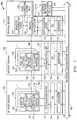
- FIG. 1is a block diagram of an example embodiment for a network traffic monitoring environment where client packet monitor applications operating within VM (virtual machine) platforms classify and encapsulate packets from monitored packet flows prior to forwarding packets to network destinations such as tool packet monitoring applications.
- VMvirtual machine
- FIG. 2is a block diagram of an example embodiment for a client VM platform that includes a client packet monitor application and stores classification-to-tag mapping data as well as other configuration data.
- FIG. 3is a block diagram of an example embodiment for a tool VM platform that includes a tool packet monitor application and stores tag-to-classification mapping data as well as other configuration data.
- FIG. 4is a diagram of an example embodiment for GRE (general routing encapsulation) headers and related classification tagging of monitored packets.
- GREgeneral routing encapsulation
- FIG. 5is a swim lane diagram of an example embodiment where received packets are tagged based upon packet classifications determined by client packet monitor application and processed by destination applications to map the tags back to classifications.
- FIG. 6is a diagram of an example embodiment for encapsulated packet data forwarded to a client packet monitor application within a VM platform using GRE headers and GRE key identifiers representing packet classifications.
- FIG. 7Ais a diagram of an example embodiment where web traffic from multiple client monitor applications within a source group is provided to multiple destination monitor applications with a destination group.
- FIG. 7Bis a diagram of an example embodiment where mail traffic from multiple client monitor applications within a source group is provided to multiple destination monitor applications with a destination group.
- FIG. 8is a block diagram of an example embodiment for a VM host server.
- FIG. 9Ais a block diagram of an example embodiment for a VM host server that uses a hypervisor to provide a virtualization layer.
- FIG. 9Bis a block diagram of an example embodiment for a VM host server that uses a container engine to provide a virtualization layer.
- the network environmentincludes one or more client applications communicating network packets within a network communication system and operating within a client VM platform in turn operating within a VM host server.
- a client packet monitor applicationalso operates within the client VM platform to monitor the network packets, to generate monitored packets representing traffic of interest, to determine packet classifications for the monitored packets based upon contents of the monitored packets, to identify tags associated with the packet classifications, to encapsulate monitored packets with encapsulation headers including the tags to form encapsulated packets, and to forward the encapsulated packets to a tool VM platform operating within a VM host server.
- a tool packet monitor applicationalso operates within the tool VM platform to receive the encapsulated packets, to identify packet classifications associated with the tags included within the encapsulated packets, to remove the encapsulation headers from the encapsulated packets to generate de-encapsulated packets, and to forward the de-encapsulated packets to one or more network destinations based upon the packet classifications.
- Multiple client VM platforms and related client packet monitor applicationscan also operate within the network communication system to forward encapsulated packets, and multiple tool VM platforms and related tool packet monitor applications can also operate within the network communication system to receive encapsulated packets.
- the tool packet monitor applicationscan also be configured to de-encapsulate the encapsulated packets and to aggregate de-encapsulated packets having the same packet classification prior to forwarding the aggregated packets to one or more network destinations.
- Different features and variationscan also be implemented, as desired, and related systems and methods can be utilized, as well.
- FIGS. 1-3provide example embodiments for virtual processing environments including client VM platforms, related client packet monitor applications, tool VM applications, related tool packet monitor applications, and traffic configuration VM platforms.
- FIGS. 4-5provide example embodiments that add encapsulation headers and classification tags to monitored packets and de-encapsulate the encapsulated packets.
- FIGS. 6-7A -Bprovide example embodiments that aggregate de-encapsulated packets having the same packet classifications.
- FIGS. 8 and 9A -Bprovide example hardware/software environments. It is further noted that other variations and features can also be implemented while still taking advantage of the client monitor application pre-classification techniques described herein.
- FIG. 1is a block diagram of an example embodiment 100 for a network traffic monitoring environment where client packet monitor applications 110 operating within VM platforms 104 , 106 , 108 . . . classify and encapsulate packets from monitored packet flows prior to forwarding packets to network destinations such as tool packet monitoring applications 130 .
- a traffic management VM platform 150operates on host server 142 and is configured to manage packet monitor applications 110 / 130 operating within VM platforms on VM host servers 102 and 122 .
- one or more client VM platforms 104 , 106 , 108 . . .operate within a first VM host server 102 ; one or more tool VM platforms 124 , 126 , 128 . . .
- the host VM servers 102 , 122 , and 142are configured to communicate with each other through one or more external network communication paths 160 .
- the external network communication paths 160can include wired network communication paths, wireless network communication paths, or a combination of wired and wireless communication paths, and the external network communication paths 160 can include one or more intervening network communication devices or systems within a network communication infrastructure. Further, one or more different communication protocols can be used within the network communication paths 160 to communicate network packets within the network communication paths 160 .
- the communications 162 , 164 , 166 , 168 , 172 , and 174can occur through the network communication paths 160 , through additional network communication paths, through direct out-of-band communication paths, and/or through other communication paths between the particular network source(s) and destination(s).
- the client VM platforms 104 , 106 , 108 . . .operate within a virtualization layer 112 that operates on top of an operating system (OS) 114 which in turn operates on computer hardware 116 .
- the computer hardware 116is coupled to communicate with the network communication paths 160 , for example, through one or more network interface cards and/or other network connections.
- the client VM platforms 104 , 106 , 108 . . .can be configured, for example, to operate in part to provide one or more network applications that communicate packets through the external network communication paths 160 and/or with each other.
- the client packet monitor application 110operates to monitor packet traffic within the client VM platform 104 , to classify monitored packet traffic, to encapsulate the classified packet traffic, and to forward copies of this encapsulated packet traffic to one or more of the tool VM platforms 124 , 126 , 128 . . . within one or more VM host servers as represented by dashed arrow 162 . Copies of packet traffic can also be forwarded to the traffic configuration platform 150 as represented by dashed arrow 166 , to external network monitoring tools 170 as represented by dashed line 174 , and/or to other network destinations.
- the client monitor application 110 within each of the VM platforms 104 , 106 , 108 . . .also stores classification-to-tag mapping data 111 .
- the classification-to-tag mapping data 111maps packet classifications to tags that are subsequently embedded within the encapsulated packets to identify the packet classifications for the monitored packet traffic. For certain example embodiments, these tags are added within a field within a GRE (generic routing encapsulation) header added to received packets before they are forwarded by the client packet monitor application 110 to network destinations such as to tool packet monitor applications 130 operating within tool VM platforms 124 , 126 , 128 . . . and/or external network monitoring tools 170 . It is noted that the classification-to-tag mapping data 111 can be stored as one or more searchable tables within one or more data storage devices.
- the tool VM platforms 124 , 126 , 128 . . .operate within a virtualization layer 132 that operates on top of an operating system (OS) 134 which in turn operates on computer hardware 136 .
- the computer hardware 136is coupled to communicate with the network communication paths 160 , for example, through one or more network interface cards and/or other network connections.
- the tool VM platforms 124 , 126 , 128 . . .can be configured, for example, to operate in part to provide one or more network packet analysis tool applications that analyze received packets.
- each of the tool VM platforms 124 , 126 , 128 . . .includes a tool packet monitor application 130 .
- the tool packet monitor application 130 within each tool VM platform 124 , 126 , 128 . . .operates to de-encapsulate monitored packet traffic received from one or more of the client packet monitor applications 110 within the client VM platforms 104 , 106 , 108 . . . and to provide this monitored traffic for further processing by tool applications also operating within the tool VM platforms 124 , 126 , 128 . . . along with the tool packet monitor application 130 .
- the tool monitor application 130 within each of the VM platforms 124 , 126 , 128 . . .also store tag-to-classification mapping data 131 .
- the tag-to-classification mapping data 131maps tags that are embedded within the encapsulated packets to associated packet classifications. For certain example embodiments, these tags are stored within a field within a GRE header added to forwarded packets by the client packet monitor applications 110 before they are forwarded to network destinations such as the tool packet monitor applications 130 operating within the tool VM platforms 124 , 126 , 128 . . . and/or external network monitoring tools 170 . It is noted that the tag-to-classification mapping data 131 can be stored as one or more searchable tables within one or more data storage devices.
- the traffic management VM platform 150operates within a virtualization layer 152 that operates on top of an operating system (OS) 154 which in turn operates on computer hardware 156 .
- the computer hardware 156is coupled to communicate with the network communication paths 160 , for example, through one or more network interface cards and/or other network connections.
- the traffic management VM platform 150can be configured, for example, to initialize, control, and/or otherwise manage the client VM monitor application(s) 110 and the tool packet monitor application(s) 130 as represented by dashed lines 164 and 166 .
- the traffic management VM platform 150can use one or more monitor configuration files 144 to initialize, configure, and/or otherwise manage the client packet monitor applications 110 and the tool packet monitor applications 130 .
- the traffic configuration VM platform 150 monitor applicationalso stores a packet classification mapping table 158 .
- the mapping table 158maps packet classifications to tags that will be embedded within the packets to identify the packet classifications by the client monitor applications 110 .
- the traffic configuration VM platform 150communicates mapping data from the packet classification mapping table 158 to the client packet monitor applications 110 , and the client packet monitor applications 110 store this mapping data as the classification-to-tag mapping data 111 .
- the traffic configuration VM platform 150also communicates mapping data from the packet classification mapping table 158 to the tool packet monitor applications 130 , and the tool packet monitor applications 130 store this mapping data as the tag-to-classification mapping data 131 .
- the tags added by the client packet monitor applications 110are tags added within a field within a GRE header added to monitored packets.
- client VM platforms 104 , 106 , 108 . . .are shown as operating within a single VM host server 102
- these client VM platformscould also be distributed among multiple VM host servers.
- tool VM platforms 124 , 126 , 128 . . .are shown as operating within VM host server 122
- these tool VM platformscould also be distributed among multiple VM host servers.
- traffic management VM platform 150is shown as operating within a single VM host server 142 , multiple traffic management VM platforms could be distributed among a plurality of VM host servers.
- the traffic management VM platform 150could also be implemented as a stand-alone processing system or device rather than a VM platform operating within a VM host server 142 . Other variations could also be implemented. Further, client VM platforms, tool VM platforms, and/or traffic management VM platforms can also be included within a common VM host server. As such, the various VM platforms for embodiment 100 can be distributed as desired among one or more VM host servers.
- the client packet monitor applications 110 within the VM platforms 104 , 106 , 108 . . .facilitate packet monitoring within the overall system by analyzing packet flows, classifying packets within those packet flows, encapsulating the monitored packets, and tagging the packets with tags that indicate the packet classifications.
- the encapsulated and tagged packetscan then be sent to one or more network destinations such as one or more tool VM platforms 124 , 126 , 128 . . . , the traffic configuration VM platform 150 , one or more external network monitoring tools 170 , and/or another network destination.
- Tool packet monitor applications 130 within network destinationreceive these encapsulated and tagged packets and use the tags along with the tag-to-classification mapping data 131 to determine the classification for the packets without having to analyze the remaining packet contents.
- This pre-classification of packets provided by the client packet monitor applications 110greatly improves the speed and efficiency of the overall network monitoring system. Further, packets with the same classifications can be aggregated and then communicated through a common data path to one or more network destination as described further below.
- client packet monitor applications 110within each of the client VM platforms 104 , 106 , 108 . . . provides a number of advantages. For example, scaling is handled implicitly as the client packet monitor applications will scale directly with the scaling of the client VM platforms. New client VM platform instances will include the client packet monitor application, and any reduction in the number of client VM platform instances will also remove any client packet monitor applications running in those client VM platform instances. In addition, by being inside the client VM platform, the client packet monitor applications 110 are also behind any load balancer feeding packets to the client VM platforms thereby allowing for any prior load balancing to still be effective.
- IP Securityis also improved and new risks are not introduced because packet security protections can remain unchanged as packets are obtained at the operating (OS) level and are obtained within a user's own network application context.
- OSoperating
- the client packet monitor applications 110have access to metadata that is outside the contents of the packet itself allowing for a broader basis for high-level forwarding configurations. For example, packet collection or filtering decisions can be made on the basis of operating system (OS), platform metadata, processing metrics (e.g., CPU load), and/or desired information apart from the packets contents themselves.
- OSoperating system
- processing metricse.g., CPU load
- FIG. 2is a block diagram of an example embodiment for a client VM platform 104 that includes a client packet monitor application 110 and stores classification-to-tag mapping data 111 as well as other configuration data 218 .
- the client packet monitor application 110includes a network TAP 212 , one or more filters 214 , tool packet interface 220 , and controller 216 .
- the tool packet interface 220also includes an encapsulation engine 222 , and the controller 216 operates to store and use classification-to-tag data 111 and other configuration (CONFIG) data 218 .
- the client VM platform 104in part operates to provide one or more client applications 202 that generate and receive packets as client traffic 204 through a virtual network interface 206 .
- the virtual network interface 206in turn communicates VM platform traffic 208 with other VM platforms operating within the same VM host server and/or with external VM platforms or systems through the network communication paths 160 .
- this VM platform traffic 208includes client traffic 204 , tool traffic 226 directed to one or more tool packet monitor applications 130 or other destinations, management traffic 228 communicated with the traffic management VM platform 150 , and any other traffic for the client VM platform 104 .
- the client network TAP 212 for the client packet monitor application 110which can be implemented as any desired virtual component that obtains copies of packets, obtains copies 224 of the client traffic 204 being communicated through the network interface 206 .
- This copied traffic 224is then processed by one or more filters 214 to identify traffic of interest for one or more network analysis tools.
- the controller 216also analyzes the contents of the traffic of interest to classify the packets based upon their packet contents and uses the classification-to-tag mapping data 111 to identify tags associated with the packet classifications.
- This traffic of interestis sent to the tool packet interface 220 which uses the encapsulation engine 222 to add encapsulation headers to the traffic of interest.
- the encapsulation engine 222also adds the tag associated with packet classification to one or more fields within the encapsulation header. As described below, these encapsulation headers can be later used by the tool packet monitor applications 130 to identify one or more tool applications to receive the traffic of interest. Further, the tags added to the encapsulation header are used to identify the classification for the packets without having to separately analyze the packet contents. For example, where GRE (generic routing encapsulation) headers are used to encapsulate monitored traffic, the encapsulation engine 222 can add GRE destination identifiers within a GRE header for each packet within the traffic of interest to identify one or more tool applications to receive that packet, and available tool applications can be assigned unique GRE destination identifiers.
- GREgenerator routing encapsulation
- the encapsulation engine 222can add a tag to a field with the GRE header, such as the key field with the GRE header, to identify the packet classification.
- the resulting encapsulated tool traffic 226is then provided back to the network interface 206 for communication out of the client VM platform 104 as part of the VM platform traffic 208 .
- the client packet monitor application 110can also have a separate network interface, if desired, such that the tool traffic 226 and the management traffic 228 are communicated through this separate network interface rather than through the network interface 206 .
- management traffic 228can be received from the traffic management VM platform 150 to provide the GRE destination identifiers for available tool applications and to provide filter configurations for the filters 214 to apply to the received client traffic 224 .
- the management traffic 228can also provide the mapping data for the classification-to-tag data 111 that is stored and used by the controller 216 .
- the client packet monitor application 110can also communicate information and/or requests back to the traffic management VM platform 150 , as desired.
- the controller 216can control the network TAP 212 , the filters 214 , and the tool packet interface 220 to operate according to management instructions received through the management traffic 228 within the VM platform traffic 208 .
- the encapsulation of the duplicated client traffic 224 by the encapsulation engine 222allows for the copied packets to be delivered to destinations different from what is defined by the original packet envelope or headers.
- a packetOnce a packet has been captured by the network TAP 212 , it is encapsulated with a header (e.g., GRE header) addressed directly to the receiving tool and tagged with the packet classification determined for the packet. With this encapsulation header in place, the packet can be placed on the general network infrastructure and processed as normal within the network communication paths 160 . The encapsulated packet will flow within the network to its intended tool VM platform based on this new envelope or header.
- a headere.g., GRE header
- This encapsulationallows for tool traffic flows to travel within the same network as data plane traffic, and no additional risks are therefore introduced with respect to existing security constraints and protections within the network infrastructure. Further, using the encapsulation headers, multiple different packet streams from multiple different client VM platforms 104 , 106 , 108 , . . . can be forwarded to one or more destination tool VM platforms 124 , 126 , 128 , . . . regardless of any security or architectural restrictions originally placed within the network infrastructure. As such, no additional or separate security management is required within the existing traffic monitoring environment for the visibility overlay provided by the disclosed embodiments. Further, by adding the classification tag within the encapsulation header, the tool packet monitor application 130 receiving the encapsulated and tagged packet can determine the packet classification from the tag within the encapsulation header without having to analyze the contents of the encapsulated packet.
- FIG. 3is a block diagram of an example embodiment for a tool VM platform 124 that includes a tool packet monitor application 130 .
- the tool packet monitor application 130includes a tool interface 312 , one or more filters 314 , client packet interface 320 , and controller 316 .
- the client packet interface 320also includes a de-encapsulation engine 322 , and the controller 316 operates to store and use tag-to-classification data 131 and other configuration (CONFIG) data 318 .
- the tool VM platform 124in part operates to provide one or more tool applications 302 that analyze received packets within client traffic 326 from the tool packet monitor application 130 .
- the tool applications 302can also send and receive other traffic 304 directly through a network interface 306 .
- the network interface 306communicates VM platform traffic 308 with other VM platforms operating within the same VM host server and/or with external VM platforms or systems through the network communication paths 160 .
- this VM platform traffic 308includes tool traffic 226 from one or more client packet monitor applications 110 , management traffic 328 communicated with the traffic management VM platform 150 , and any other traffic for the tool VM platform 124 .
- the client packet interface 320receives the encapsulated tool traffic 226 communicated by the client packet monitor application 110 within one or more client VM platforms.
- the client packet interface 320uses the de-encapsulation engine 322 to remove encapsulation headers from the traffic of interest within the encapsulated tool traffic 226 .
- the controller 316also reads the classification tag within the encapsulation header and uses the tag-to-classification mapping data 131 to determine the packet classification associated with the tag. For example, where GRE headers are used, the de-encapsulation engine 322 can remove GRE headers and use GRE destination identifiers within those header to identify one or more tool applications 302 to receive that packet. As indicated above, available tool applications 302 can be assigned unique GRE destination identifiers.
- the encapsulation engine 222can extract the classification tag from the GRE header, and the controller 216 can determine the packet classification from the tag using the tag-to-classification data 131 without having to separately analyze additional packet contents.
- packets from different sources or packet flows with the same packet classificationcan be aggregated by the tool packet monitor application 130 prior to being output one or more tool applications 302 .
- the de-encapsulated trafficcan also be processed by one or more filters 314 to further select traffic of interest and/or desired tool destinations for the traffic of interest.
- the filtered traffic of interestis then provided to the tool interface 312 , and this resulting client traffic 326 is communicated to the one or more tool applications 302 .
- Result information from the tool applications 302can then be communicated back through the network interface 306 as part of the VM platform traffic 308 .
- the tool packet monitor application 130can also have a separate network interface, if desired, such that the tool traffic 226 and the management traffic 328 are communicated through this separate network interface rather than through the network interface 306 .
- management traffic 328can be received from the traffic management VM platform 150 to provide the GRE destination identifiers for available tool applications 302 and to provide filter configurations for the filters 314 .
- the management traffic 328can also provide the mapping data for the tag-to-classification data 131 stored and used by the controller 216 .
- the tool packet monitor application 130can also communicate information and/or requests back to the traffic management VM platform 150 , as desired.
- the controller 316can control the client packet interface 320 , the filters 314 , and the tool interface 312 to operate according to management instructions received through the management traffic 328 within the VM platform traffic 308 .
- the tool applications 302can instead terminate the tunnel directly.
- the encapsulation tunnels providing packets from one or more client packet monitor applications 110can be terminated more efficiently, and associated packet traffic can be aggregated down to a single stream of relevant traffic using the controller 316 and/or filters 314 .
- the tool packet monitor application 130can remove processing and filtering requirements that would otherwise have to be implemented by the tool applications 302 with respect to termination and aggregation of the tool traffic 226 to form the resulting client traffic 326 .
- the pre-classification and associated tags provided by the client packet monitor applications 110allow for rapid determinations by filters 314 of resulting destinations for the packets.
- the filters 214 / 314can rely upon various portions of the content of network packets to identify packets and to determine which tool application is to receive the packets.
- filters 214 / 314can be configured to rely upon data and/or information associated with any network layer header values or packet field contents to perform such actions.
- packet-based communicationsare often described in terms of seven communication layers under the ISO/OSI (International Standards Organization/Open Systems Interconnect) model: application layer (L7), presentation layer (L6), session layer (L5), transport layer (L4), network layer (L3), data link layer (L2), and physical layer (L1).
- ISO/OSIInternational Standards Organization/Open Systems Interconnect
- Packet headers associated with any of these layers as well as packet data payload contentscan be used by the filters 214 / 314 .
- information pertinent to identifying a packetsuch as source ID and destination ID and protocol type, is often found in one or more network layer headers. Packets also have various other identification fields and content information within them that may be matched and used to collect and aggregate information about packets and related packet flows.
- the filters 214 / 314are operating as part of the packet monitor application 110 / 130 inside of the client VM platforms, the filters 214 / 314 can also rely upon non-packet content related information to determine tool destinations for the tool traffic 226 .
- information concerning application states, message states, operating system, and/or other information that is not within the packets themselvescan be used by the filters 214 / 314 .
- packet content and non-packet content related data and informationcan be identified and used by the filters 214 / 314 .
- configuration files 144 , the configuration data 218 / 318 , the packet classification mapping table 158 , the classification-to-tag mapping data 111 , and the tag-to-classification mapping data 131 described abovecan be stored within one or more data storage systems, and these data storage systems can be implemented using one or more non-transitory tangible computer-readable mediums such as FLASH memory, random access memory, read only memory, programmable memory devices, reprogrammable storage devices, hard drives, floppy disks, DVDs, CD-ROMs, and/or any other non-transitory data storage mediums.
- non-transitory tangible computer-readable mediumssuch as FLASH memory, random access memory, read only memory, programmable memory devices, reprogrammable storage devices, hard drives, floppy disks, DVDs, CD-ROMs, and/or any other non-transitory data storage mediums.
- VM host servers 102 , 122 , and 142can be implemented using one or more programmable integrated circuits to provide the functionality described herein.
- processorse.g., microprocessor, microcontroller, central processing unit, etc.
- configurable logic devicese.g., CPLD (complex programmable logic device), FPGA (field programmable gate array), etc.
- CPLDcomplex programmable logic device
- FPGAfield programmable gate array
- other programmable integrated circuitcan be programmed with software or other programming instructions to implement the functionality described herein.
- software or other programming instructions for such programmable integrated circuitscan be implemented as software or programming instructions embodied in one or more non-transitory computer-readable mediums (e.g., memory storage devices, FLASH memory, DRAM memory, reprogrammable storage devices, hard drives, floppy disks, DVDs, CD-ROMs, etc.) including software or programming instructions that when executed by the programmable integrated circuits cause them to perform the processes, functions, and/or capabilities described herein for the VM host servers 102 , 122 , and 142 and their respective components.
- non-transitory computer-readable mediumse.g., memory storage devices, FLASH memory, DRAM memory, reprogrammable storage devices, hard drives, floppy disks, DVDs, CD-ROMs, etc.
- FIG. 4is a diagram of an example embodiment 400 for GRE encapsulation and related classification tagging of monitored packets.
- packet 402represents a packet received by a client packet monitor application 110 .
- the packet 402includes a packet header 404 and a packet payload 406 , and the packet 402 can be formatted according to one or more network protocols such as Ethernet network protocols.
- the client packet monitor application 110analyzes the contents of the received packet being monitored to classify the packet, to filter the packet, and/or to process the packet according to other parameters provided for in the configuration data 218 .
- the client packet monitor application 110determines a classification for the packet based upon the packet content analysis, as represented by bracket 407 , and adds an encapsulation header to the monitored packet, such as a GRE header, to form an encapsulated packet 408 that includes a tag 422 identifying the classification.
- the encapsulated packet 408includes the original packet header 404 , the original payload 406 , and the encapsulation header 410 , which is a GRE header for the example embodiment 400 .
- a field within the encapsulation header 410includes the tag 422 that identifies the classification 420 for the received packet, an address for the target network destination (e.g., tool client monitor application) for the encapsulated packet, and/or other information.
- the GRE header 410includes fields for an IP (Internet Protocol) header 411 , one or more GRE flags 412 , a protocol type 414 , a key 416 , and a sequence number 418 .
- the IP header 411is used as a delivery header and includes a destination IP address for the target network destination (e.g., tool client monitor application) for the GRE encapsulated packet.
- the GRE flags 412are used to indicate the presence of additional fields for the GRE header 410 and/or other information.
- the protocol type 414is used to indicate the type of GRE protocol being used.
- the key 416is often not used for standard GRE headers; however, for the embodiments described herein the key 416 is used to store the tag 422 that identifies the packet classification 420 .
- a flagcan be set in the GRE flags 412 to indicate that a GRE key field has been included within the GRE header.
- the sequence number 418is used to identify individual packets that are sequentially related to each other so that one or more dropped packets can be more easily detected.
- the tag 422 that is stored with the key field 416is determined from the classification-to-tag mapping data 111 .
- This classification-to-tag mapping data 111maps the packet classifications 420 to tags 422 .
- a first packet classification (CLASS1)is mapped to a first tag (TAG1).
- a second packet classification (CLASS2)is mapped to a second tag (TAG2).
- an Nth packet classification (CLASS(N))being mapped to an Nth tag (TAG(N)).
- the packet classificationscan indicate one or more of variety of conditions and content types for the received packets.
- packetscan be classified based upon packet sources, packet destinations, communication types (e.g., email, voice, data, web, etc.), and/or other packet content related parameters.
- the tagscan be unique multiple-bit digital words, such as 32-bit digital words with a different 32-bit value being associated each unique packet classification. Other variations could also be implemented.
- FIG. 5is a swim lane diagram of an example embodiment 500 where received packets are tagged based upon packet classifications determined by client packet monitor application 110 and processed by destination applications 130 to map the tags back to classifications.
- communications and related processingare shown for a management platform 150 , a client packet monitor application 110 , and a destination (e.g., tool monitor) application 130 .
- the management platform 150communicates classification/tag mapping data to the monitor application 110 and to the destination application 130 through one or more messages 502 .
- the monitor application 110stores the mapping data as classification-to-tag data 111
- the destination application 130stores the mapping data as tag-to-classification data 131 .
- the management platform 150can also communicate packet filter configuration information to the client packet monitor application 110 through one or more messages 504 .
- the monitor application 110than applies one or more filters to received packet flows based upon the packet filter configuration information.
- the monitor application 110also analyzes the contents of received packets and classifies the packets.
- the monitor application 110then maps the packet classifications to packet tags using the classification-to-tag mapping data 111 , and the packets are then tagged with the identified tags.
- the monitor application 110then sends the tagged packets to the destination application 130 through one or more messages 512 .
- the destination application 130then reads the tags within the tagged packets and maps the tags to packet classifications using the tag-to-classification mapping data 131 . As indicated by process block 516 , the destination application 130 then processes the packets based upon the packet classifications without having to analyze the additional contents of the packet itself to determine their classification.
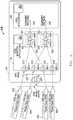
- FIG. 6is a diagram of an example embodiment 600 for encapsulated packet data forwarded to a client packet monitor application 130 within a VM platform 124 using GRE encapsulation headers and GRE key identifiers representing packet classifications.
- packet data 602 and packet data 604are received by VM platform 124 from a first client packet monitor application designated with 1.1.1.1 as an IP address
- packet data 606 and packet data 608are received by VM platform 124 from a second client packet monitor application designated with 1.1.1.2 as an IP address.
- the VM platform 124is designated with 2.1.1.1 as an IP address.
- packet data 602is encapsulated with a GRE header that includes a first GRE key (KEY 1)
- packet data 604is encapsulated with a GRE header that includes a second GRE key (KEY 2).
- packet data 606is encapsulated with a GRE header that includes the first GRE key (KEY 1)
- packet data 608is encapsulated with a GRE header that includes the second GRE key (KEY 2).
- the first GRE key (KEY 1)is associated with web traffic
- the second GRE key (KEY 2)is associated with email traffic.
- IP addressesare included as a simplified example, and different IP and/or other source addresses could be assigned depending upon the network environment.
- the GRE encapsulated packet data 602 / 604 / 606 / 608is received by a virtual network interface card (vNIC) 610 for the VM platform (eth0) 124 .
- the monitor application 130receives the GRE encapsulated packets from the vNIC 610 and de-encapsulates the GRE encapsulation. Based upon this GRE de-encapsulation (GRE DECAP), the monitor application 130 effectively processes the different flows of packet data 602 , 604 , 606 , and 608 using different vNICs 612 , 614 , 616 , and 618 that together provide the functionality of the vNIC 610 .
- the first vNIC (pktc0.1) 612receives and de-encapsulates the packet data 602 , identifies the tag to be the first GRE key (KEY 1), maps the first GRE key (KEY 1) to web traffic as the packet classification, and sends the classified packets to a packet aggregator 620 for web traffic.
- the second vNIC (pktc0.2) 614receives and de-encapsulates the packet data 604 , identifies the tag to be the second GRE key (KEY 2), maps the second GRE key (KEY 2) to mail traffic as the packet classification, and sends the classified packets to a packet aggregator 630 for mail traffic.
- the third vNIC (pktc1.1) 616receives and de-encapsulates the packet data 606 , identifies the tag to be the first GRE key (KEY 1), maps the first GRE key (KEY 1) to web traffic as the packet classification, and sends the classified packets to a packet aggregator 620 for web traffic.
- the fourth vNIC (pktc1.2) 618receives and de-encapsulates the packet data 608 , identifies the tag to be the second GRE key (KEY 2), maps the second GRE key (KEY 2) to mail traffic as the packet classification, and sends the classified packets to a packet aggregator 630 for mail traffic.
- the first packet aggregator 620aggregates the web related traffic and outputs the aggregated web traffic 626 to a first port for a tool application 302 , for example, using a promiscuous raw socket.
- the first packet aggregator 620includes an input vNIC (web0.in) 622 that aggregates the incoming packets from the vNICs 612 / 616 and outputs the aggregated web packets to an output vNIC (web0) 624 .
- the second packet aggregator 630aggregates the web related traffic and outputs the aggregated web traffic to a second port for the tool application 302 , for example, using a promiscuous raw socket.
- the second packet aggregator 630includes an input vNIC (mail0.in) 632 that aggregates the incoming packets from the vNICs 614 / 618 and outputs the aggregated mail packets to an output vNIC (mail0) 634 .
- the tool application 302then processes the web traffic 626 and the mail traffic 636 .
- the tool application 302an also be multiple tool applications that are used to process the aggregated web/mail traffic 626 / 636 .
- example embodiment 600 of FIG. 6shows a single tool monitor application 130 and a single tool application or VM platform 302
- multiple tool monitor applications 130can receive the encapsulated traffic and multiple tool applications.
- additional tool monitor applications 130 as well as additional tool applications 302can be dynamically added where additional processing resources are needed.
- U.S. patent application Ser. No. 14/873,896entitled “DIRECT NETWORK TRAFFIC MONITORING WITHIN VM PLATFORMS IN VIRTUAL PROCESSING ENVIRONMENTS” and filed Oct. 2, 2015, describes various embodiments that provide load balancing and dynamic application resources related to source/destination groups. This U.S. patent application Ser. No. 14/873,896 is again hereby incorporated by reference in its entirety.
- FIG. 7Ais a diagram of an example embodiment 700 where web traffic from multiple client monitor applications 110 A-E within a source group 702 is provided to multiple destination monitor applications 130 A-B with a destination group 704 .
- the packets within the flows for packet data 706 , 708 , 710 , 712 , and 714are encapsulated with GRE headers and all include a first GRE key (KEY 1) that identifies web traffic as the packet classification.
- Web trafficcan be identified, for example, through a filter that identifies packets directed to TCP Port 80 .
- a first source groupincludes client monitor applications 110 A, 110 B, and 110 C.
- the client monitor application 110 A with IP address 1.1.1.1sends packet data 706 that is received by a first destination monitor application 130 A with IP address 2.1.1.1.
- the client monitor application 110 B with IP address 1.1.1.2sends packet data 708 that is also received by the first destination monitor application 130 A.
- the client monitor application 110 C with IP address 1.1.1.3sends packet data 710 that is also received by the first destination monitor application 130 A.
- the packet data 706 , 708 , and 710are all encapsulated with GRE headers that include the first GRE key (KEY 1) as a tag that identifies web traffic as the packet classification.
- the first destination monitor application 130 Aaggregates the web packet traffic from the client monitor applications 110 A/ 110 B/ 110 C and then outputs the aggregated web traffic through a network interface (web0) to a destination for further packet processing.
- a second source groupincludes client monitor applications 110 D and 110 E.
- the client monitor application 110 D with IP address 1.1.1.4sends packet data 712 that is received by a second destination monitor application 130 B with IP address 2.1.1.2.
- the client monitor application 110 E with IP address 1.1.1.5sends packet data 714 that is also received by the second destination monitor application 130 B.
- the packet data 712 and 714are all encapsulated with GRE headers that include the second GRE key (KEY 2) as a tag that identifies mail traffic as the packet classification.
- the second destination monitor application 130 Baggregates the web packet traffic from the client monitor applications 110 C/ 110 D and then outputs the aggregated web traffic through a network interface (web0) to a destination for further packet processing.
- FIG. 7Bis a diagram of an example embodiment 750 where mail traffic from multiple client monitor applications 110 A-E within a source group 702 is provided to multiple destination monitor applications 130 A-B with a destination group 704 .
- Example embodiment 750operates the same as example embodiment 700 of FIG. 7A except that the packet traffic being forwarded is mail traffic instead of web traffic.
- the packets within packet data tunnels 706 , 708 , 710 , 712 , and 714are encapsulated with GRE headers and all include a second GRE key (KEY 2) that identifies mail traffic as the packet classification.
- Mail trafficcan be identified, for example, through a filter that identifies and passes packets director to TCP Port 25 .
- a first source groupincludes client monitor applications 110 A, 110 B, and 110 C.
- the client monitor application 110 A with IP address 1.1.1.1sends packet data 706 that is received by a first destination monitor application 130 A with IP address 2.1.1.1.
- the client monitor application 110 B with IP address 1.1.1.2sends packet data 708 that is also received by the first destination monitor application 130 A.
- the client monitor application 110 C with IP address 1.1.1.3sends packet data 710 that is also received by the first destination monitor application 130 A.
- the packet data 706 , 708 , and 710are all encapsulated with GRE headers that include the first GRE key (KEY 1) as a tag that identifies mail traffic as the packet classification.
- the first destination monitor application 130 Aaggregates the mail packet traffic from the client monitor applications 110 A/ 110 B/ 110 C and then outputs the aggregated mail traffic through a network interface (mail0) to a destination for further packet processing.
- a second source groupincludes client monitor applications 110 D and 110 E.
- the client monitor application 110 D with IP address 1.1.1.4sends packet data 712 that is received by a second destination monitor application 130 B with IP address 2.1.1.2.
- the client monitor application 110 E with IP address 1.1.1.5sends packet data 714 that is also received by the second destination monitor application 130 B.
- the packet data 712 and 714are all encapsulated with GRE headers that include the second GRE key (KEY 2) as a tag that identifies mail traffic as the packet classification.
- the second destination monitor application 130 Baggregates the mail packet traffic from the client monitor applications 110 C/ 110 D and then outputs the aggregated mail traffic through a network interface (mail0) to a destination for further packet processing.
- FIG. 8is a block diagram of an example embodiment for a VM host server 102 / 122 / 142 .
- the VM host server 102 / 122 / 142includes one or processors 802 or other programmable integrated circuits to provide a virtualization layer 112 / 132 / 152 including a plurality of virtual machine (VM) platforms 812 , 814 , . . . 816 that run one or more applications as described herein.
- VMvirtual machine
- the VM host server 102 / 122 / 142also includes one or more network interface cards (NICs) 804 , one or more input/output (I/O) ports 806 , one or more data storage systems 808 , and memory 803 coupled to communicate with each other through a system bus interconnect 810 .
- NICsnetwork interface cards
- I/Oinput/output
- memory 803coupled to communicate with each other through a system bus interconnect 810 .
- virtualization layer 112 / 132 / 152 and the VM platforms (VM1, VM2 . . . VM(N)) 812 , 814 , . . . 816run on top of a VM host operating system (OS) 114 / 134 / 154 .
- OSVM host operating system
- the VM host operating system 114 / 134 / 154 , the virtualization layer 112 / 132 / 152 , and the VM platforms 812 , 814 , . . . 816can be initialized, controlled, and operated by the processors or programmable integrated circuits 802 which load and execute software code and/or programming instructions stored in the data storage systems 808 to perform the functions described herein.
- the VM platforms 812 , 814 , . . . 816can be client VM platforms, tool VM platforms, and/or traffic management VM platforms, as described above.
- the memory 803can include one or more memory devices that store program instructions and/or data used for operation of the VM host server 102 / 122 / 142 .
- the processor(s) 802can load software or program instructions stored in the data storage systems 808 into the memory 803 and then execute the software or program instructions to perform the operations and functions described herein.
- one or more of the processors 802 or other programmable integrated circuit(s)can also be programmed with code or logic instructions stored in the data storage systems 808 to perform the operations and functions described herein.
- data storage system(s) 808 and the memory 803can be implemented using one or more non-transitory tangible computer-readable mediums, such as for example, data storage devices, FLASH memory devices, random access memory (RAM) devices, read only memory (ROM) devices, other programmable memory devices, reprogrammable storage devices, hard drives, floppy disks, DVDs, CD-ROMs, and/or other non-transitory data storage mediums.
- non-transitory tangible computer-readable mediumssuch as for example, data storage devices, FLASH memory devices, random access memory (RAM) devices, read only memory (ROM) devices, other programmable memory devices, reprogrammable storage devices, hard drives, floppy disks, DVDs, CD-ROMs, and/or other non-transitory data storage mediums.
- the programmable integrated circuitscan include one or more processors (e.g., central processing units (CPUs), controllers, microcontrollers, microprocessors, hardware accelerators, ASICs (application specific integrated circuit), and/or other integrated processing devices) and/or one or more programmable logic devices (e.g., CPLDs (complex programmable logic devices), FPGAs (field programmable gate arrays), PLAs (programmable logic array), reconfigurable logic circuits, and/or other integrated logic devices).
- processorse.g., central processing units (CPUs), controllers, microcontrollers, microprocessors, hardware accelerators, ASICs (application specific integrated circuit), and/or other integrated processing devices
- programmable logic devicese.g., CPLDs (complex programmable logic devices), FPGAs (field programmable gate arrays), PLAs (programmable logic array), reconfigurable logic circuits, and/or other integrated logic devices.
- CPLDscomplex programmable logic devices
- the virtualization layer 112 / 132 / 152 for the VM platforms described hereincan be implemented using any desired virtualization layer, such as using a hypervisor or a container engine, that provides a virtual processing environment for the VM platforms.
- a hypervisoras shown in FIG. 9A below, the client/tool packet monitor application 110 / 130 operates in addition to an application 902 / 912 on a guest operating system within one of the VM platforms 812 / 814 which in turn run on top of the hypervisor as the virtualization layer 112 / 132 / 152 .
- a container engineas shown in FIG.
- the client/tool packet monitor application 110 / 130operates along with applications 902 / 912 within a VM platform 812 that operates on top of the container engine.
- the VM platform 812 for this embodimentoperates as a virtual computing platform without the emulated hardware (HW) 908 and without the guest operating system (OS) 906 that are shown with respect to the embodiment of FIG. 9A .
- the applications 902 / 912 as well as the client/tool packet monitor application 110 / 130are containers or other software components within a single VM platform 812 .
- the container enginecan be implemented as a DOCKER container for a Linux operating system configured to execute DOCKER containers, which are software components that are designed to be compatible with a Linux-based DOCKER container engine. Other variations could also be implemented.
- FIG. 9Ais a block diagram of an example embodiment 900 for a VM host server 102 / 122 / 132 that uses a hypervisor to provide a virtualization layer 112 / 132 / 152 .
- VM platforms 812 and 814operate on top of hypervisor 112 / 132 / 152 which in turn operates on top of host operating system (OS) 114 / 134 / 154 which in turn operates on top of server hardware 116 / 136 / 156 .
- OShost operating system
- the VM host server 102 / 122 / 142provides emulated hardware (HW) resources 908 and a guest operating system (OS) 906 for VM platform 812 , and VM platform 812 executes binary code (BINS) or libraries (LIBS) 904 on top of the guest operating system 906 to provide a first application (APP A) 902 .
- the VM host server 102 / 122 / 142provides emulated hardware (HW) resources 918 and a guest operating system (OS) 916 for VM platform 814 , and VM platform 814 executes binary code (BINS) or libraries (LIBS) 914 on top of guest operating system 916 to provide a second application (APP B) 912 .
- HWhardware
- OSguest operating system
- LIBSlibraries
- each of the VM platforms 812 and 814have separate emulated hardware resources 908 / 918 and guest operating systems 906 / 916 .
- a client/tool packet monitor application 110 / 130when installed can operate within one of the VM platforms 812 / 814 on top of the guest OS 906 / 916 along with one of the application 902 / 912 .
- FIG. 9Bis a block diagram of an example embodiment 950 for a VM host server 102 / 122 / 132 that uses a container engine to provide a virtualization layer 112 / 132 / 152 .
- VM platform 812operates on top of container engine 112 / 132 / 152 which in turn operates on top of host operating system (OS) 114 / 134 / 154 which in turn operates on top of server hardware 116 / 136 / 156 .
- OShost operating system
- the VM platform 812executes binary code (BINS) or libraries (LIBS) 904 directly on top of the container engine 112 / 132 / 152 to provide a first application (APP A) 902 and executes binary code (BINS) or libraries (LIBS) 914 directly on top of the container engine 112 / 132 / 152 to provide a second application (APP B) 912 .
- the container engine 112 / 132 / 152provides a direct interface to the host operating system 114 / 134 / 154 without need for emulated hardware (HW) resources 908 / 918 and/or guest operating systems 906 / 916 as used in FIG. 9A .
- HWemulated hardware
- a client/tool packet monitor application 110 / 130when installed can operate along with the other applications 902 / 912 on top of the container engine 112 / 132 / 152 within the VM platform 812 .
- the functional blocks, components, systems, devices, and/or circuitry described hereincan be implemented using hardware, software, or a combination of hardware and software.
- the disclosed embodimentscan be implemented using one or more programmable integrated circuits that are programmed to perform the functions, tasks, methods, actions, and/or other operational features described herein for the disclosed embodiments.
- the one or more programmable integrated circuitscan include, for example, one or more processors and/or PLDs (programmable logic devices).
- the one or more processorscan be, for example, one or more central processing units (CPUs), controllers, microcontrollers, microprocessors, hardware accelerators, ASICs (application specific integrated circuit), and/or other integrated processing devices.
- the one or more PLDscan be, for example, one or more CPLDs (complex programmable logic devices), FPGAs (field programmable gate arrays), PLAs (programmable logic array), reconfigurable logic circuits, and/or other integrated logic devices.
- the programmable integrated circuitsincluding the one or more processors, can be configured to execute software, firmware, code, and/or other program instructions that are embodied in one or more non-transitory tangible computer-readable mediums to perform the functions, tasks, methods, actions, and/or other operational features described herein for the disclosed embodiments.
- the programmable integrated circuitscan also be programmed using logic code, logic definitions, hardware description languages, configuration files, and/or other logic instructions that are embodied in one or more non-transitory tangible computer-readable mediums to perform the functions, tasks, methods, actions, and/or other operational features described herein for the disclosed embodiments.
- the one or more non-transitory tangible computer-readable mediumscan include, for example, one or more data storage devices, memory devices, flash memories, random access memories, read only memories, programmable memory devices, reprogrammable storage devices, hard drives, floppy disks, DVDs, CD-ROMs, and/or any other non-transitory tangible computer-readable mediums.
- Other variationscan also be implemented while still taking advantage of the client monitor application pre-classification techniques described herein.
Landscapes
- Engineering & Computer Science (AREA)
- Computer Networks & Wireless Communication (AREA)
- Signal Processing (AREA)
- Computer Security & Cryptography (AREA)
- Data Exchanges In Wide-Area Networks (AREA)
Abstract
Description
Claims (26)
Priority Applications (1)
| Application Number | Priority Date | Filing Date | Title |
|---|---|---|---|
| US15/342,170US10652112B2 (en) | 2015-10-02 | 2016-11-03 | Network traffic pre-classification within VM platforms in virtual processing environments |
Applications Claiming Priority (2)
| Application Number | Priority Date | Filing Date | Title |
|---|---|---|---|
| US14/873,896US10116528B2 (en) | 2015-10-02 | 2015-10-02 | Direct network traffic monitoring within VM platforms in virtual processing environments |
| US15/342,170US10652112B2 (en) | 2015-10-02 | 2016-11-03 | Network traffic pre-classification within VM platforms in virtual processing environments |
Related Parent Applications (1)
| Application Number | Title | Priority Date | Filing Date |
|---|---|---|---|
| US14/873,896Continuation-In-PartUS10116528B2 (en) | 2015-10-02 | 2015-10-02 | Direct network traffic monitoring within VM platforms in virtual processing environments |
Publications (2)
| Publication Number | Publication Date |
|---|---|
| US20170099197A1 US20170099197A1 (en) | 2017-04-06 |
| US10652112B2true US10652112B2 (en) | 2020-05-12 |
Family
ID=58446938
Family Applications (1)
| Application Number | Title | Priority Date | Filing Date |
|---|---|---|---|
| US15/342,170Active2036-02-10US10652112B2 (en) | 2015-10-02 | 2016-11-03 | Network traffic pre-classification within VM platforms in virtual processing environments |
Country Status (1)
| Country | Link |
|---|---|
| US (1) | US10652112B2 (en) |
Cited By (1)
| Publication number | Priority date | Publication date | Assignee | Title |
|---|---|---|---|---|
| US20220232111A1 (en)* | 2019-05-23 | 2022-07-21 | Hewlett Packard Enterprise Development Lp | Systems and methods for per traffic class routing |
Families Citing this family (42)
| Publication number | Priority date | Publication date | Assignee | Title |
|---|---|---|---|---|
| US10033693B2 (en) | 2013-10-01 | 2018-07-24 | Nicira, Inc. | Distributed identity-based firewalls |
| US9891940B2 (en) | 2014-12-29 | 2018-02-13 | Nicira, Inc. | Introspection method and apparatus for network access filtering |
| US10652112B2 (en) | 2015-10-02 | 2020-05-12 | Keysight Technologies Singapore (Sales) Pte. Ltd. | Network traffic pre-classification within VM platforms in virtual processing environments |
| US10116528B2 (en) | 2015-10-02 | 2018-10-30 | Keysight Technologies Singapore (Holdings) Ptd Ltd | Direct network traffic monitoring within VM platforms in virtual processing environments |
| US10324746B2 (en) | 2015-11-03 | 2019-06-18 | Nicira, Inc. | Extended context delivery for context-based authorization |
| US10135702B2 (en) | 2015-11-12 | 2018-11-20 | Keysight Technologies Singapore (Holdings) Pte. Ltd. | Methods, systems, and computer readable media for testing network function virtualization (NFV) |
| US10579792B2 (en)* | 2015-11-23 | 2020-03-03 | Armor Defense Inc. | Extracting malicious instructions on a virtual machine |
| US9967165B2 (en)* | 2015-12-07 | 2018-05-08 | Keysight Technologies Singapore (Holdings) Pte. Ltd. | Methods, systems, and computer readable media for packet monitoring in a virtual environment |
| KR102389028B1 (en)* | 2016-01-04 | 2022-04-22 | 한국전자통신연구원 | Apparatus and method for high speed data transfer between virtual desktop |
| US10938837B2 (en) | 2016-08-30 | 2021-03-02 | Nicira, Inc. | Isolated network stack to manage security for virtual machines |
| US10193863B2 (en)* | 2016-10-07 | 2019-01-29 | Microsoft Technology Licensing, Llc | Enforcing network security policy using pre-classification |
| WO2018106612A1 (en)* | 2016-12-06 | 2018-06-14 | Nicira, Inc. | Performing context-rich attribute-based services on a host |
| US11032246B2 (en) | 2016-12-22 | 2021-06-08 | Nicira, Inc. | Context based firewall services for data message flows for multiple concurrent users on one machine |
| US10581960B2 (en) | 2016-12-22 | 2020-03-03 | Nicira, Inc. | Performing context-rich attribute-based load balancing on a host |
| US10812451B2 (en) | 2016-12-22 | 2020-10-20 | Nicira, Inc. | Performing appID based firewall services on a host |
| US10803173B2 (en) | 2016-12-22 | 2020-10-13 | Nicira, Inc. | Performing context-rich attribute-based process control services on a host |
| US10805332B2 (en) | 2017-07-25 | 2020-10-13 | Nicira, Inc. | Context engine model |
| US10503536B2 (en) | 2016-12-22 | 2019-12-10 | Nicira, Inc. | Collecting and storing threat level indicators for service rule processing |
| US10142263B2 (en) | 2017-02-21 | 2018-11-27 | Keysight Technologies Singapore (Holdings) Pte Ltd | Packet deduplication for network packet monitoring in virtual processing environments |
| US11012327B2 (en)* | 2017-06-19 | 2021-05-18 | Keysight Technologies Singapore (Sales) Pte. Ltd. | Drop detection and protection for network packet monitoring in virtual processing environments |
| US10862904B2 (en) | 2017-07-21 | 2020-12-08 | Red Hat, Inc. | Container intrusion detection and prevention system |
| KR101981334B1 (en)* | 2017-09-14 | 2019-05-22 | 에스케이텔레콤 주식회사 | Mobile communication system and method applying distributed data packet handling |
| US10778651B2 (en) | 2017-11-15 | 2020-09-15 | Nicira, Inc. | Performing context-rich attribute-based encryption on a host |
| CN108173676A (en)* | 2017-12-13 | 2018-06-15 | 浙江工商职业技术学院 | A data intelligent filtering method |
| US10862773B2 (en) | 2018-01-26 | 2020-12-08 | Nicira, Inc. | Performing services on data messages associated with endpoint machines |
| US10802893B2 (en) | 2018-01-26 | 2020-10-13 | Nicira, Inc. | Performing process control services on endpoint machines |
| CN110351160B (en)* | 2018-04-08 | 2021-12-14 | 华为技术有限公司 | Method and apparatus for monitoring service quality |
| US11991061B2 (en) | 2018-06-25 | 2024-05-21 | British Telecommunications Public Limited Company | Processing local area network diagnostic data |
| US11196649B2 (en) | 2018-06-25 | 2021-12-07 | British Telecommunications Public Limited Company | Processing local area network diagnostic data |
| GB2575245B (en)* | 2018-06-25 | 2020-11-25 | British Telecomm | Processing local area network diagnostic data |
| US11398968B2 (en) | 2018-07-17 | 2022-07-26 | Keysight Technologies, Inc. | Methods, systems, and computer readable media for testing virtualized network functions and related infrastructure |
| CN110784835A (en)* | 2018-07-31 | 2020-02-11 | 中兴通讯股份有限公司 | Data traffic processing method and device, terminal and computer storage medium |
| WO2021063671A1 (en) | 2019-09-30 | 2021-04-08 | British Telecommunications Public Limited Company | Processing local area network diagnostic data |
| US11539718B2 (en) | 2020-01-10 | 2022-12-27 | Vmware, Inc. | Efficiently performing intrusion detection |
| US11641316B2 (en)* | 2020-06-29 | 2023-05-02 | Lenovo Enterprise Solutions (Singapore) Pte. Ltd. | Capturing data packets for analysis using a virtual machine |
| US11108728B1 (en) | 2020-07-24 | 2021-08-31 | Vmware, Inc. | Fast distribution of port identifiers for rule processing |
| US11323354B1 (en) | 2020-10-09 | 2022-05-03 | Keysight Technologies, Inc. | Methods, systems, and computer readable media for network testing using switch emulation |
| US11483227B2 (en) | 2020-10-13 | 2022-10-25 | Keysight Technologies, Inc. | Methods, systems and computer readable media for active queue management |
| US11853254B1 (en) | 2022-10-07 | 2023-12-26 | Keysight Technologies, Inc. | Methods, systems, and computer readable media for exposing data processing unit (DPU) traffic in a smartswitch |
| US12407600B2 (en) | 2022-11-03 | 2025-09-02 | Keysight Technologies, Inc. | Methods, systems, and computer readable media for smartswitch service chaining |
| US20250211505A1 (en)* | 2023-12-20 | 2025-06-26 | Arista Networks, Inc. | Using Generic Routing Encapsulation (GRE) for Carrying Monitored Network Traffic |
| US20250274368A1 (en)* | 2024-02-28 | 2025-08-28 | Arista Networks, Inc. | Metadata Preservation for Network Traffic |
Citations (82)
| Publication number | Priority date | Publication date | Assignee | Title |
|---|---|---|---|---|
| US5515376A (en) | 1993-07-19 | 1996-05-07 | Alantec, Inc. | Communication apparatus and methods |
| US20010022786A1 (en) | 1998-04-20 | 2001-09-20 | Wai King | Receive processing for dedicated bandwidth data communication switch backplane |
| US6321259B1 (en) | 1998-10-02 | 2001-11-20 | Nortel Networks Limited | Attribute inheritance schema for network switches |
| US20010055274A1 (en) | 2000-02-22 | 2001-12-27 | Doug Hegge | System and method for flow mirroring in a network switch |
| US20020186259A1 (en) | 2001-04-20 | 2002-12-12 | General Instrument Corporation | Graphical user interface for a transport multiplexer |
| US20030046657A1 (en) | 2001-08-15 | 2003-03-06 | Jason White | Creating a graphical program to configure one or more switch devices |
| US20030074421A1 (en) | 2001-08-14 | 2003-04-17 | Mieko Kusano | Internet access via specific server and via proprietary application for selecting and controlling content: remote and local |
| US6578147B1 (en) | 1999-01-15 | 2003-06-10 | Cisco Technology, Inc. | Parallel intrusion detection sensors with load balancing for high speed networks |
| US20040003094A1 (en) | 2002-06-27 | 2004-01-01 | Michael See | Method and apparatus for mirroring traffic over a network |
| US20040042470A1 (en) | 2000-06-16 | 2004-03-04 | Geoffrey Cooper | Method and apparatus for rate limiting |
| US20040103321A1 (en) | 1996-02-06 | 2004-05-27 | Wesinger Ralph E. | Firewall providing enhanced network security and user transparency |
| US20040107361A1 (en) | 2002-11-29 | 2004-06-03 | Redan Michael C. | System for high speed network intrusion detection |
| US6785286B1 (en) | 1999-05-25 | 2004-08-31 | 3Com Corporation | Port mirroring across a trunked stack of multi-port communication devices |
| US20040196841A1 (en) | 2003-04-04 | 2004-10-07 | Tudor Alexander L. | Assisted port monitoring with distributed filtering |
| US6839349B2 (en) | 1999-12-07 | 2005-01-04 | Broadcom Corporation | Mirroring in a stacked network switch configuration |
| US6853623B2 (en) | 1999-03-05 | 2005-02-08 | Cisco Technology, Inc. | Remote monitoring of switch network |
| US20050053073A1 (en) | 2003-09-03 | 2005-03-10 | Andiamo Systems, Inc. A Delaware Corporation | Switch port analyzers |
| US6901517B1 (en) | 1999-07-16 | 2005-05-31 | Marconi Communications, Inc. | Hardware based security groups, firewall load sharing, and firewall redundancy |
| US6920112B1 (en) | 1998-06-29 | 2005-07-19 | Cisco Technology, Inc. | Sampling packets for network monitoring |
| US20050182950A1 (en) | 2004-02-13 | 2005-08-18 | Lg N-Sys Inc. | Network security system and method |
| US6954775B1 (en) | 1999-01-15 | 2005-10-11 | Cisco Technology, Inc. | Parallel intrusion detection sensors with load balancing for high speed networks |
| US7016980B1 (en) | 2000-01-18 | 2006-03-21 | Lucent Technologies Inc. | Method and apparatus for analyzing one or more firewalls |
| US7027437B1 (en) | 1999-05-21 | 2006-04-11 | Advanced Micro Devices, Inc. | Network switch multiple-port sniffing |
| US20060256788A1 (en) | 2001-12-28 | 2006-11-16 | Donahue David B | System and method for content filtering using static source routes |
| US7142518B2 (en) | 2001-09-03 | 2006-11-28 | Agilent Technologies, Inc. | Monitoring communications networks |
| US7143196B2 (en) | 2002-05-06 | 2006-11-28 | Silverstorm Technologies, Inc | System and method for span port configuration |
| US7245620B2 (en) | 2002-03-15 | 2007-07-17 | Broadcom Corporation | Method and apparatus for filtering packet data in a network device |
| US7254114B1 (en) | 2002-08-26 | 2007-08-07 | Juniper Networks, Inc. | Network router having integrated flow accounting and packet interception |
| US7310306B1 (en) | 2001-10-16 | 2007-12-18 | Cisco Technology, Inc. | Method and apparatus for ingress port filtering for packet switching systems |
| US20080008202A1 (en) | 2002-10-31 | 2008-01-10 | Terrell William C | Router with routing processors and methods for virtualization |
| US20080072292A1 (en) | 2006-09-01 | 2008-03-20 | Narjala Ranjit S | Secure device introduction with capabilities assessment |
| US20080201455A1 (en) | 2007-02-15 | 2008-08-21 | Husain Syed M Amir | Moving Execution of a Virtual Machine Across Different Virtualization Platforms |
| US7424018B2 (en) | 2004-05-05 | 2008-09-09 | Gigamon Systems Llc | Asymmetric packet switch and a method of use |
| US20080222731A1 (en) | 2000-01-14 | 2008-09-11 | Secure Computing Corporation | Network security modeling system and method |
| US20090007021A1 (en) | 2007-06-28 | 2009-01-01 | Richard Hayton | Methods and systems for dynamic generation of filters using a graphical user interface |
| US20090013052A1 (en) | 1998-12-18 | 2009-01-08 | Microsoft Corporation | Automated selection of appropriate information based on a computer user's context |
| US20090150996A1 (en) | 2007-12-11 | 2009-06-11 | International Business Machines Corporation | Application protection from malicious network traffic |
| US7554984B2 (en) | 2004-11-30 | 2009-06-30 | Broadcom Corporation | Fast filter processor metering and chaining |
| US20090172148A1 (en) | 2007-12-26 | 2009-07-02 | Verizon Business Network Services Inc. | Method and system for monitoring and analyzing of ip networks elements |
| US20090238192A1 (en)* | 2008-03-21 | 2009-09-24 | Alcatel Lucent | In-band DPI application awareness propagation enhancements |
| US20090327903A1 (en) | 2006-07-06 | 2009-12-31 | Referentia Systems, Inc. | System and Method for Network Topology and Flow Visualization |
| US20100017801A1 (en) | 2008-07-18 | 2010-01-21 | Vmware, Inc. | Profile based creation of virtual machines in a virtualization environment |
| US20100027554A1 (en) | 2008-07-30 | 2010-02-04 | Jiri Kuthan | Methods, systems, and computer readable media for implementing a policy for a router |
| US7688727B1 (en) | 2000-04-17 | 2010-03-30 | Juniper Networks, Inc. | Filtering and route lookup in a switching device |
| US7769873B1 (en) | 2002-10-25 | 2010-08-03 | Juniper Networks, Inc. | Dynamically inserting filters into forwarding paths of a network device |
| US20100332618A1 (en) | 2007-11-09 | 2010-12-30 | Norton Richard Elliott | Method and apparatus for filtering streaming data |
| US20110004698A1 (en) | 2009-07-01 | 2011-01-06 | Riverbed Technology, Inc. | Defining Network Traffic Processing Flows Between Virtual Machines |
| US7889711B1 (en) | 2005-07-29 | 2011-02-15 | Juniper Networks, Inc. | Filtering traffic based on associated forwarding equivalence classes |
| US8018943B1 (en) | 2009-07-31 | 2011-09-13 | Anue Systems, Inc. | Automatic filter overlap processing and related systems and methods |
| US8098677B1 (en) | 2009-07-31 | 2012-01-17 | Anue Systems, Inc. | Superset packet forwarding for overlapping filters and related systems and methods |
| US20120079107A1 (en) | 2003-02-14 | 2012-03-29 | Preventsys, Inc. | System and Method for Interfacing with Heterogeneous Network Data Gathering Tools |
| US8151348B1 (en)* | 2004-06-30 | 2012-04-03 | Cisco Technology, Inc. | Automatic detection of reverse tunnels |
| US8156209B1 (en)* | 2001-02-15 | 2012-04-10 | Cisco Technology, Inc. | Aggregation devices processing keep-alive messages of point-to-point sessions |
| US20120099602A1 (en) | 2010-10-25 | 2012-04-26 | Brocade Communications Systems, Inc. | End-to-end virtualization |
| US8200203B1 (en) | 2003-03-21 | 2012-06-12 | Stratosaudio, Inc. | Broadcast response method and system |
| US20120210318A1 (en) | 2011-02-10 | 2012-08-16 | Microsoft Corporation | Virtual switch interceptor |
| US20130031233A1 (en) | 2011-07-29 | 2013-01-31 | International Business Machines Corporation | Network filtering in a virtualized environment |
| US20130060940A1 (en)* | 2010-07-06 | 2013-03-07 | Teemu Koponen | Network virtualization |
| US20130291109A1 (en) | 2008-11-03 | 2013-10-31 | Fireeye, Inc. | Systems and Methods for Scheduling Analysis of Network Content for Malware |
| US20130297769A1 (en)* | 2012-05-02 | 2013-11-07 | Cisco Technology, Inc. | System and method for simulating virtual machine migration in a network environment |
| US20140105216A1 (en)* | 2012-10-17 | 2014-04-17 | Verizon Patent And Licensing Inc. | Network devices with feature peer network logic |
| US20140115584A1 (en)* | 2011-06-07 | 2014-04-24 | Hewlett-Packard Development Company L.P. | Scalable multi-tenant network architecture for virtualized datacenters |
| US20140229605A1 (en) | 2013-02-12 | 2014-08-14 | Sharon Shalom Besser | Arrangements for monitoring network traffic on a cloud-computing environment and methods thereof |
| US8914406B1 (en)* | 2012-02-01 | 2014-12-16 | Vorstack, Inc. | Scalable network security with fast response protocol |
| US8934495B1 (en) | 2009-07-31 | 2015-01-13 | Anue Systems, Inc. | Filtering path view graphical user interfaces and related systems and methods |
| US20150124828A1 (en)* | 2013-11-06 | 2015-05-07 | Citrix Systems, Inc | Systems and methods for port allocation |
| US20150180769A1 (en)* | 2013-12-20 | 2015-06-25 | Alcatel-Lucent Usa Inc. | Scale-up of sdn control plane using virtual switch based overlay |
| US9075642B1 (en) | 2011-09-30 | 2015-07-07 | Emc Corporation | Controlling access to resources using independent and nested hypervisors in a storage system environment |
| US9110703B2 (en) | 2011-06-07 | 2015-08-18 | Hewlett-Packard Development Company, L.P. | Virtual machine packet processing |
| US20150263889A1 (en) | 2014-03-14 | 2015-09-17 | Network Critical Solutions Limited | Network packet broker |
| US20150319030A1 (en) | 2014-04-30 | 2015-11-05 | Youval Nachum | Smartap arrangement and methods thereof |
| US20150334628A1 (en) | 2012-12-13 | 2015-11-19 | Samsung Electronics Co., Ltd. | Method and device for transferring data traffic |
| US20160065386A1 (en)* | 2014-08-29 | 2016-03-03 | Alcatel -Lucent Usa, Inc. | Scalable virutal networks in sdn-based ethernet networks using vlans |
| US20160094418A1 (en) | 2014-09-30 | 2016-03-31 | Anue Systems, Inc. | Selective Scanning of Network Packet Traffic Using Cloud-Based Virtual Machine Tool Platforms |
| US20160110211A1 (en) | 2014-10-15 | 2016-04-21 | Anue Systems, Inc. | Methods And Systems For Forwarding Network Packets Within Virtual Machine Host Systems |
| US20160359872A1 (en)* | 2015-06-05 | 2016-12-08 | Cisco Technology, Inc. | System for monitoring and managing datacenters |
| US20170083354A1 (en)* | 2015-09-22 | 2017-03-23 | Amazon Technologies, Inc. | Connection-based resource management for virtual desktop instances |
| US20170099195A1 (en) | 2015-10-02 | 2017-04-06 | Ixia | Direct Network Traffic Monitoring Within VM Platforms In Virtual Processing Environments |
| US20170099197A1 (en) | 2015-10-02 | 2017-04-06 | Ixia | Network Traffic Pre-Classification Within VM Platforms In Virtual Processing Environments |
| US20170149670A1 (en)* | 2014-03-31 | 2017-05-25 | Telefonaktiebolaget Lm Ericsson (Publ) | Handling of traffic flows in a communications system |
| US20170163510A1 (en) | 2015-12-07 | 2017-06-08 | Ixia | Methods, systems, and computer readable media for packet monitoring in a virtual environment |
| US20170208037A1 (en)* | 2014-06-23 | 2017-07-20 | Yissum Research Development Company Of The Hebrew University Of Jerusalem Ltd. | Method and system for providing deep packet inspection as a service |
- 2016
- 2016-11-03USUS15/342,170patent/US10652112B2/enactiveActive
Patent Citations (92)
| Publication number | Priority date | Publication date | Assignee | Title |
|---|---|---|---|---|
| US5515376A (en) | 1993-07-19 | 1996-05-07 | Alantec, Inc. | Communication apparatus and methods |
| US20040103321A1 (en) | 1996-02-06 | 2004-05-27 | Wesinger Ralph E. | Firewall providing enhanced network security and user transparency |
| US20010022786A1 (en) | 1998-04-20 | 2001-09-20 | Wai King | Receive processing for dedicated bandwidth data communication switch backplane |
| US6920112B1 (en) | 1998-06-29 | 2005-07-19 | Cisco Technology, Inc. | Sampling packets for network monitoring |
| US6321259B1 (en) | 1998-10-02 | 2001-11-20 | Nortel Networks Limited | Attribute inheritance schema for network switches |
| US20090013052A1 (en) | 1998-12-18 | 2009-01-08 | Microsoft Corporation | Automated selection of appropriate information based on a computer user's context |
| US6954775B1 (en) | 1999-01-15 | 2005-10-11 | Cisco Technology, Inc. | Parallel intrusion detection sensors with load balancing for high speed networks |
| US6578147B1 (en) | 1999-01-15 | 2003-06-10 | Cisco Technology, Inc. | Parallel intrusion detection sensors with load balancing for high speed networks |
| US6853623B2 (en) | 1999-03-05 | 2005-02-08 | Cisco Technology, Inc. | Remote monitoring of switch network |
| US7027437B1 (en) | 1999-05-21 | 2006-04-11 | Advanced Micro Devices, Inc. | Network switch multiple-port sniffing |
| US6785286B1 (en) | 1999-05-25 | 2004-08-31 | 3Com Corporation | Port mirroring across a trunked stack of multi-port communication devices |
| US6901517B1 (en) | 1999-07-16 | 2005-05-31 | Marconi Communications, Inc. | Hardware based security groups, firewall load sharing, and firewall redundancy |
| US6839349B2 (en) | 1999-12-07 | 2005-01-04 | Broadcom Corporation | Mirroring in a stacked network switch configuration |
| US20080222731A1 (en) | 2000-01-14 | 2008-09-11 | Secure Computing Corporation | Network security modeling system and method |
| US7016980B1 (en) | 2000-01-18 | 2006-03-21 | Lucent Technologies Inc. | Method and apparatus for analyzing one or more firewalls |
| US20010055274A1 (en) | 2000-02-22 | 2001-12-27 | Doug Hegge | System and method for flow mirroring in a network switch |
| US7688727B1 (en) | 2000-04-17 | 2010-03-30 | Juniper Networks, Inc. | Filtering and route lookup in a switching device |
| US7917647B2 (en) | 2000-06-16 | 2011-03-29 | Mcafee, Inc. | Method and apparatus for rate limiting |
| US20040042470A1 (en) | 2000-06-16 | 2004-03-04 | Geoffrey Cooper | Method and apparatus for rate limiting |
| US8156209B1 (en)* | 2001-02-15 | 2012-04-10 | Cisco Technology, Inc. | Aggregation devices processing keep-alive messages of point-to-point sessions |
| US20020186259A1 (en) | 2001-04-20 | 2002-12-12 | General Instrument Corporation | Graphical user interface for a transport multiplexer |
| US6996779B2 (en) | 2001-04-20 | 2006-02-07 | General Instrument Corporation | Graphical user interface for a transport multiplexer |
| US20030074421A1 (en) | 2001-08-14 | 2003-04-17 | Mieko Kusano | Internet access via specific server and via proprietary application for selecting and controlling content: remote and local |
| US20030046657A1 (en) | 2001-08-15 | 2003-03-06 | Jason White | Creating a graphical program to configure one or more switch devices |
| US7142518B2 (en) | 2001-09-03 | 2006-11-28 | Agilent Technologies, Inc. | Monitoring communications networks |
| US7310306B1 (en) | 2001-10-16 | 2007-12-18 | Cisco Technology, Inc. | Method and apparatus for ingress port filtering for packet switching systems |
| US20060256788A1 (en) | 2001-12-28 | 2006-11-16 | Donahue David B | System and method for content filtering using static source routes |
| US7245620B2 (en) | 2002-03-15 | 2007-07-17 | Broadcom Corporation | Method and apparatus for filtering packet data in a network device |
| US7143196B2 (en) | 2002-05-06 | 2006-11-28 | Silverstorm Technologies, Inc | System and method for span port configuration |
| US20040003094A1 (en) | 2002-06-27 | 2004-01-01 | Michael See | Method and apparatus for mirroring traffic over a network |
| US7254114B1 (en) | 2002-08-26 | 2007-08-07 | Juniper Networks, Inc. | Network router having integrated flow accounting and packet interception |
| US7769873B1 (en) | 2002-10-25 | 2010-08-03 | Juniper Networks, Inc. | Dynamically inserting filters into forwarding paths of a network device |
| US20080008202A1 (en) | 2002-10-31 | 2008-01-10 | Terrell William C | Router with routing processors and methods for virtualization |
| US20040107361A1 (en) | 2002-11-29 | 2004-06-03 | Redan Michael C. | System for high speed network intrusion detection |
| US20120079107A1 (en) | 2003-02-14 | 2012-03-29 | Preventsys, Inc. | System and Method for Interfacing with Heterogeneous Network Data Gathering Tools |
| US8200203B1 (en) | 2003-03-21 | 2012-06-12 | Stratosaudio, Inc. | Broadcast response method and system |
| US20040196841A1 (en) | 2003-04-04 | 2004-10-07 | Tudor Alexander L. | Assisted port monitoring with distributed filtering |
| US20050053073A1 (en) | 2003-09-03 | 2005-03-10 | Andiamo Systems, Inc. A Delaware Corporation | Switch port analyzers |
| US20050182950A1 (en) | 2004-02-13 | 2005-08-18 | Lg N-Sys Inc. | Network security system and method |
| US7424018B2 (en) | 2004-05-05 | 2008-09-09 | Gigamon Systems Llc | Asymmetric packet switch and a method of use |
| US8151348B1 (en)* | 2004-06-30 | 2012-04-03 | Cisco Technology, Inc. | Automatic detection of reverse tunnels |
| US7554984B2 (en) | 2004-11-30 | 2009-06-30 | Broadcom Corporation | Fast filter processor metering and chaining |
| US7889711B1 (en) | 2005-07-29 | 2011-02-15 | Juniper Networks, Inc. | Filtering traffic based on associated forwarding equivalence classes |
| US20090327903A1 (en) | 2006-07-06 | 2009-12-31 | Referentia Systems, Inc. | System and Method for Network Topology and Flow Visualization |
| US20080072292A1 (en) | 2006-09-01 | 2008-03-20 | Narjala Ranjit S | Secure device introduction with capabilities assessment |
| US20080201455A1 (en) | 2007-02-15 | 2008-08-21 | Husain Syed M Amir | Moving Execution of a Virtual Machine Across Different Virtualization Platforms |
| US20090007021A1 (en) | 2007-06-28 | 2009-01-01 | Richard Hayton | Methods and systems for dynamic generation of filters using a graphical user interface |
| US20100332618A1 (en) | 2007-11-09 | 2010-12-30 | Norton Richard Elliott | Method and apparatus for filtering streaming data |
| US8447718B2 (en) | 2007-11-09 | 2013-05-21 | Vantrix Corporation | Method and apparatus for filtering streaming data |
| US20090150996A1 (en) | 2007-12-11 | 2009-06-11 | International Business Machines Corporation | Application protection from malicious network traffic |
| US20090172148A1 (en) | 2007-12-26 | 2009-07-02 | Verizon Business Network Services Inc. | Method and system for monitoring and analyzing of ip networks elements |
| US20090238192A1 (en)* | 2008-03-21 | 2009-09-24 | Alcatel Lucent | In-band DPI application awareness propagation enhancements |
| US20100017801A1 (en) | 2008-07-18 | 2010-01-21 | Vmware, Inc. | Profile based creation of virtual machines in a virtualization environment |
| US20100027554A1 (en) | 2008-07-30 | 2010-02-04 | Jiri Kuthan | Methods, systems, and computer readable media for implementing a policy for a router |
| US20130291109A1 (en) | 2008-11-03 | 2013-10-31 | Fireeye, Inc. | Systems and Methods for Scheduling Analysis of Network Content for Malware |
| US20110004698A1 (en) | 2009-07-01 | 2011-01-06 | Riverbed Technology, Inc. | Defining Network Traffic Processing Flows Between Virtual Machines |
| US8098677B1 (en) | 2009-07-31 | 2012-01-17 | Anue Systems, Inc. | Superset packet forwarding for overlapping filters and related systems and methods |
| US20110317694A1 (en) | 2009-07-31 | 2011-12-29 | Anue Systems, Inc. | Automatic filter overlap processing and related systems and methods |
| US8902895B2 (en) | 2009-07-31 | 2014-12-02 | Anue Systems, Inc. | Automatic filter overlap processing and related systems and methods |
| US20120106354A1 (en) | 2009-07-31 | 2012-05-03 | Anue Systems, Inc. | Superset packet forwarding for overlapping filters and related systems and methods |
| US8018943B1 (en) | 2009-07-31 | 2011-09-13 | Anue Systems, Inc. | Automatic filter overlap processing and related systems and methods |
| US8842548B2 (en) | 2009-07-31 | 2014-09-23 | Anue Systems, Inc. | Superset packet forwarding for overlapping filters and related systems and methods |
| US8934495B1 (en) | 2009-07-31 | 2015-01-13 | Anue Systems, Inc. | Filtering path view graphical user interfaces and related systems and methods |
| US20130060940A1 (en)* | 2010-07-06 | 2013-03-07 | Teemu Koponen | Network virtualization |
| US20120099602A1 (en) | 2010-10-25 | 2012-04-26 | Brocade Communications Systems, Inc. | End-to-end virtualization |
| US20120210318A1 (en) | 2011-02-10 | 2012-08-16 | Microsoft Corporation | Virtual switch interceptor |
| US9110703B2 (en) | 2011-06-07 | 2015-08-18 | Hewlett-Packard Development Company, L.P. | Virtual machine packet processing |
| US20140115584A1 (en)* | 2011-06-07 | 2014-04-24 | Hewlett-Packard Development Company L.P. | Scalable multi-tenant network architecture for virtualized datacenters |
| US20130031233A1 (en) | 2011-07-29 | 2013-01-31 | International Business Machines Corporation | Network filtering in a virtualized environment |
| US9075642B1 (en) | 2011-09-30 | 2015-07-07 | Emc Corporation | Controlling access to resources using independent and nested hypervisors in a storage system environment |
| US8914406B1 (en)* | 2012-02-01 | 2014-12-16 | Vorstack, Inc. | Scalable network security with fast response protocol |
| US20130297769A1 (en)* | 2012-05-02 | 2013-11-07 | Cisco Technology, Inc. | System and method for simulating virtual machine migration in a network environment |
| US20140105216A1 (en)* | 2012-10-17 | 2014-04-17 | Verizon Patent And Licensing Inc. | Network devices with feature peer network logic |
| US20150334628A1 (en) | 2012-12-13 | 2015-11-19 | Samsung Electronics Co., Ltd. | Method and device for transferring data traffic |
| US20140229605A1 (en) | 2013-02-12 | 2014-08-14 | Sharon Shalom Besser | Arrangements for monitoring network traffic on a cloud-computing environment and methods thereof |
| US9680728B2 (en) | 2013-02-12 | 2017-06-13 | Ixia | Arrangements for monitoring network traffic on a cloud-computing environment and methods thereof |
| US20150124828A1 (en)* | 2013-11-06 | 2015-05-07 | Citrix Systems, Inc | Systems and methods for port allocation |
| US20150180769A1 (en)* | 2013-12-20 | 2015-06-25 | Alcatel-Lucent Usa Inc. | Scale-up of sdn control plane using virtual switch based overlay |
| US20150263889A1 (en) | 2014-03-14 | 2015-09-17 | Network Critical Solutions Limited | Network packet broker |
| US20170149670A1 (en)* | 2014-03-31 | 2017-05-25 | Telefonaktiebolaget Lm Ericsson (Publ) | Handling of traffic flows in a communications system |
| US20150319030A1 (en) | 2014-04-30 | 2015-11-05 | Youval Nachum | Smartap arrangement and methods thereof |
| US20170208037A1 (en)* | 2014-06-23 | 2017-07-20 | Yissum Research Development Company Of The Hebrew University Of Jerusalem Ltd. | Method and system for providing deep packet inspection as a service |
| US20160065386A1 (en)* | 2014-08-29 | 2016-03-03 | Alcatel -Lucent Usa, Inc. | Scalable virutal networks in sdn-based ethernet networks using vlans |
| WO2016053666A1 (en) | 2014-09-30 | 2016-04-07 | Anue Systems, Inc. | Selective scanning of network packet traffic using cloud-based virtual machine tool platforms |
| US20160094418A1 (en) | 2014-09-30 | 2016-03-31 | Anue Systems, Inc. | Selective Scanning of Network Packet Traffic Using Cloud-Based Virtual Machine Tool Platforms |
| US20160110211A1 (en) | 2014-10-15 | 2016-04-21 | Anue Systems, Inc. | Methods And Systems For Forwarding Network Packets Within Virtual Machine Host Systems |
| US20160359872A1 (en)* | 2015-06-05 | 2016-12-08 | Cisco Technology, Inc. | System for monitoring and managing datacenters |
| US20170083354A1 (en)* | 2015-09-22 | 2017-03-23 | Amazon Technologies, Inc. | Connection-based resource management for virtual desktop instances |
| US20170099195A1 (en) | 2015-10-02 | 2017-04-06 | Ixia | Direct Network Traffic Monitoring Within VM Platforms In Virtual Processing Environments |
| US20170099197A1 (en) | 2015-10-02 | 2017-04-06 | Ixia | Network Traffic Pre-Classification Within VM Platforms In Virtual Processing Environments |
| US10116528B2 (en) | 2015-10-02 | 2018-10-30 | Keysight Technologies Singapore (Holdings) Ptd Ltd | Direct network traffic monitoring within VM platforms in virtual processing environments |
| US20170163510A1 (en) | 2015-12-07 | 2017-06-08 | Ixia | Methods, systems, and computer readable media for packet monitoring in a virtual environment |
Non-Patent Citations (34)
| Title |
|---|
| A. Esson and J. Mannos, "Broadcom BCM5600 StrataSwitch; A Highly Integrated Ethernet Switch on a Chip," Broadcom Corporation, Hot Chips Aug. 17, 1999. |
| Advisory Action dated Mar. 7, 2018, Kristopher Raney, "Direct Network Traffic Monitoring Within VM Platforms in Virtual Processing Environments" U.S. Appl. No. 14/873,896, filed Oct. 2, 2015, 4 pgs. |
| Advisory Action mailed Mar. 7, 2018, Kristopher Raney, "Direct Network Traffic Monitoring Within VM Platforms in Virtual Processing Environments" U.S. Appl. No. 14/873,896, filed Oct. 2, 2015, 4 pgs. |
| European Search Report; Application No. 16852312.4; dated Jan. 3, 2019, 8 pgs. |
| European Search Report; Application No. 16852312.4; dated Mar. 1, 2019, 8 pgs. |
| F. Muhtar, "Appliances to Boost Network Defence," CyberSecurity Malaysia, Nov. 26, 2001. |
| Final Office Action dated Dec. 1, 2017, Kristopher Raney, "Direct Network Traffic Monitoring Within VM Platforms in Virtual Processing Environments" U.S. Appl. No. 14/873,896, filed Oct. 2, 2015, 29 pgs. |
| G. Marshall, SC Magazine Reprint, "Attack Mitigator," Aug. 2002. |
| Hofstede et al., "Flow Monitoring Explained: From Packet Capture to Data Analysis With NetFlow and IPFIX", IEEE, 31 pgs. (May 2014). |
| Ixia, "A Paradigm Shift for Network Visibility: Delivering Better Data for Better Decisions", Rev. A. May 2014, 14 pgs. |
| Ixia, "Ixia Application and Threat Intelligence Processor", Data Sheet, May 2014, 3 pgs. |
| Ixia, "Ixia xFilter", Data Sheet, May 2015, 5 pgs. |
| Ixia, Ixia Flex Tap, Data Sheet, 5 pgs. (Oct. 2015). |
| Ixia, Ixia Phantom vTap With TapFlow Filtering, Data Sheet, 4 pgs. (Jul. 2015). |
| J. Magee, "The Case for IDS Balancing vs. a Switch," Top Layer Networks, Inc., May 2003. |
| Kristopher Raney, "Selective Scanning of Network Packet Traffic Using Cloud-Based Virtual Machine Tool Platforms," U.S. Appl. No. 14/501,717, filed Sep. 30, 2014. |
| National Information Assurance Partnership, Common Criteria Evaluation and Validation Scheme, Validation Report; Top Layer Networks; IDS BalancerTM Version 2.2 Appliance (IDSB3531-CCV1.0, IDSB3532-CCV1.0, IDSB4508-CCV1.0), Report No. CCEVS-VR-04-0074, National Institute of Standards and Technology; National Security Agency, Sep. 3, 2004. |
| Notice of Allowance dated Jun. 15, 2018, Kristopher Raney, "Direct Network Traffic Monitoring Within VM Platforms in Virtual Processing Environments" U.S. Appl. No. 14/873,896, filed Oct. 2, 2015, 5 pgs. |
| Notice of Allowance dated Jun. 17, 2018, Kristopher Raney, "Direct Network Traffic Monitoring Within VM Platforms in Virtual Processing Environments" U.S. Appl. No. 14/873,896, filed Oct. 2, 2015, 5 pgs. |
| Office Action dated Jun. 15, 2017, Kristopher Raney, "Direct Network Traffic Monitoring Within VM Platforms in Virtual Processing Environments" U.S. Appl. No. 14/873,896, filed Oct. 2, 2015, 21 pgs. |
| Radware, "Radware's Smart IDS Management; FireProof and Intrusion Detection Systems; Deployment and ROI," North America Radware, Inc.; International Radware, Ltd., Aug. 21, 2002. |
| Response to Advisory Action filed Apr. 2, 2018, Kristopher Raney, "Direct Network Traffic Monitoring Within VM Platforms in Virtual Processing Environments" U.S. Appl. No. 14/873,896, filed Oct. 2, 2015, 11 pgs. |
| Response to Final Office Action filed Feb. 1, 2018, Kristopher Raney, "Direct Network Traffic Monitoring Within VM Platforms in Virtual Processing Environments" U.S. Appl. No. 14/873,896, filed Oct. 2, 2015, 10 pgs. |
| Response to Office Action filed Sep. 14, 2017, Kristopher Raney, "Direct Network Traffic Monitoring Within VM Platforms in Virtual Processing Environments" U.S. Appl. No. 14/873,896, filed Oct. 2, 2015, 12 pgs. |
| S. Edwards, "Vulnerabilities of Network Intrusion Detection Systems: Realizing and Overcoming the Risks; The Case for Flow Mirroring," Top Layer Networks, Inc., May 1, 2002. |
| SC Magazine Reprint, "IDS Balancer 3500 Appliance," Jul. 2002. |
| Search Report and Written Opinion, PCT/US2016/052589; dated Nov. 18, 2016, 13 pgs. |
| Top Layer Networks, Inc., "APP Switch 2500; The Original Top Layer Device to Perfect the Art of Network Security," internet advertisement, www.TopLayer.com. 2001. |
| Top Layer Networks, Inc., "Case Study-IDS Balancer; Building an Intelligent Monitoring Layer Using the Top Layer IDS Balancer Ensures Full Security Coverage for University of California, Irvine," www.TopLayer.com; 2003. |
| Top Layer Networks, Inc., "IDS Balancer 3.0 Delivers Ultimate Flexibility in Selecting, Filtering and Distributing Network Traffic," Press Release, Oct. 20, 2004. |
| Top Layer Networks, Inc., "IDS Balancer; Aggregation, Filtering, & Load Appliance," internet advertisement, ww.TopLayer.com., 2004. |
| Top Layer Networks, Inc., "Product Enhancements Optimize Existing Network Intrusion Detection and Prevention Environments," Press Release, Aug. 18, 2003. |
| Top Layer Networks, Inc., "Top Layer Advances Scaleable Intrusion Detection With Industry Leading Multi-Gigabit Offering," Press Release, Mar. 10, 2003. |
| Top Layer Networks, Inc., "Case Study—IDS Balancer; Building an Intelligent Monitoring Layer Using the Top Layer IDS Balancer Ensures Full Security Coverage for University of California, Irvine," www.TopLayer.com; 2003. |
Cited By (2)
| Publication number | Priority date | Publication date | Assignee | Title |
|---|---|---|---|---|
| US20220232111A1 (en)* | 2019-05-23 | 2022-07-21 | Hewlett Packard Enterprise Development Lp | Systems and methods for per traffic class routing |
| US11962490B2 (en)* | 2019-05-23 | 2024-04-16 | Hewlett Packard Enterprise Development Lp | Systems and methods for per traffic class routing |
Also Published As
| Publication number | Publication date |
|---|---|
| US20170099197A1 (en) | 2017-04-06 |
Similar Documents
| Publication | Publication Date | Title |
|---|---|---|
| US10652112B2 (en) | Network traffic pre-classification within VM platforms in virtual processing environments | |
| US10116528B2 (en) | Direct network traffic monitoring within VM platforms in virtual processing environments | |
| US10177936B2 (en) | Quality of service (QoS) for multi-tenant-aware overlay virtual networks | |
| CN108540381B (en) | Computing method, computing device, and computer-readable storage medium | |
| CN114189571B (en) | Apparatus and method for implementing accelerated network packet processing | |
| US9838277B2 (en) | Packet copy management for service chain processing within virtual processing systems | |
| US10887361B2 (en) | Port mirroring in overlay networks | |
| US9971619B2 (en) | Methods and systems for forwarding network packets within virtual machine host systems | |
| US9729512B2 (en) | Use of stateless marking to speed up stateful firewall rule processing | |
| US9825913B2 (en) | Use of stateless marking to speed up stateful firewall rule processing | |
| US8804747B2 (en) | Network interface controller for virtual and distributed services | |
| US10142263B2 (en) | Packet deduplication for network packet monitoring in virtual processing environments | |
| EP3419221B1 (en) | Drop detection and protection for network packet monitoring in virtual processing environments | |
| US10877822B1 (en) | Zero-copy packet transmission between virtualized computing instances | |
| US20180191680A1 (en) | Intercepting network traffic routed by virtual switches for selective security processing | |
| US10178003B2 (en) | Instance based management and control for VM platforms in virtual processing environments | |
| US10581730B2 (en) | Packet processing using service chains | |
| US20160110212A1 (en) | Methods And Systems For Network Packet Impairment Within Virtual Machine Host Systems | |
| US12081336B2 (en) | Packet drop monitoring in a virtual router | |
| WO2015187201A1 (en) | Use of stateless marking to speed up stateful firewall rule processing | |
| CN111163004B (en) | Service chain data processing method and device and computer equipment | |
| US10541842B2 (en) | Methods and apparatus for enhancing virtual switch capabilities in a direct-access configured network interface card | |
| US9473396B1 (en) | System for steering data packets in communication network | |
| US11811559B2 (en) | Logical network packet handling on physical network interface controller (PNIC) | |
| US11750532B2 (en) | Logical network packet handling on physical network interface controller (PNIC) |
Legal Events
| Date | Code | Title | Description |
|---|---|---|---|
| AS | Assignment | Owner name:IXIA, CALIFORNIA Free format text:ASSIGNMENT OF ASSIGNORS INTEREST;ASSIGNOR:RANEY, KRISTOPHER;REEL/FRAME:040207/0998 Effective date:20161102 | |
| AS | Assignment | Owner name:KEYSIGHT TECHNOLOGIES SINGAPORE (HOLDINGS) PTE. LTD., SINGAPORE Free format text:ASSIGNMENT OF ASSIGNORS INTEREST;ASSIGNOR:IXIA;REEL/FRAME:044222/0695 Effective date:20170930 Owner name:KEYSIGHT TECHNOLOGIES SINGAPORE (HOLDINGS) PTE. LT Free format text:ASSIGNMENT OF ASSIGNORS INTEREST;ASSIGNOR:IXIA;REEL/FRAME:044222/0695 Effective date:20170930 | |
| AS | Assignment | Owner name:KEYSIGHT TECHNOLOGIES SINGAPORE (SALES) PTE. LTD., Free format text:ASSIGNMENT OF ASSIGNORS INTEREST;ASSIGNOR:KEYSIGHT TECHNOLOGIES SINGAPORE (HOLDINGS) PTE. LTD.;REEL/FRAME:048225/0065 Effective date:20181001 Owner name:KEYSIGHT TECHNOLOGIES SINGAPORE (SALES) PTE. LTD., SINGAPORE Free format text:ASSIGNMENT OF ASSIGNORS INTEREST;ASSIGNOR:KEYSIGHT TECHNOLOGIES SINGAPORE (HOLDINGS) PTE. LTD.;REEL/FRAME:048225/0065 Effective date:20181001 | |
| STPP | Information on status: patent application and granting procedure in general | Free format text:FINAL REJECTION MAILED | |
| STPP | Information on status: patent application and granting procedure in general | Free format text:NON FINAL ACTION MAILED | |
| STPP | Information on status: patent application and granting procedure in general | Free format text:RESPONSE TO NON-FINAL OFFICE ACTION ENTERED AND FORWARDED TO EXAMINER | |
| STPP | Information on status: patent application and granting procedure in general | Free format text:NOTICE OF ALLOWANCE MAILED -- APPLICATION RECEIVED IN OFFICE OF PUBLICATIONS | |
| STCF | Information on status: patent grant | Free format text:PATENTED CASE | |
| MAFP | Maintenance fee payment | Free format text:PAYMENT OF MAINTENANCE FEE, 4TH YEAR, LARGE ENTITY (ORIGINAL EVENT CODE: M1551); ENTITY STATUS OF PATENT OWNER: LARGE ENTITY Year of fee payment:4 |