US10651147B2 - Signal isolator having bidirectional communication between die - Google Patents
Signal isolator having bidirectional communication between dieDownload PDFInfo
- Publication number
- US10651147B2 US10651147B2US15/702,937US201715702937AUS10651147B2US 10651147 B2US10651147 B2US 10651147B2US 201715702937 AUS201715702937 AUS 201715702937AUS 10651147 B2US10651147 B2US 10651147B2
- Authority
- US
- United States
- Prior art keywords
- die
- sensing element
- magnetic sensing
- coil
- transmitter
- Prior art date
- Legal status (The legal status is an assumption and is not a legal conclusion. Google has not performed a legal analysis and makes no representation as to the accuracy of the status listed.)
- Active
Links
Images


Classifications
- H—ELECTRICITY
- H04—ELECTRIC COMMUNICATION TECHNIQUE
- H04B—TRANSMISSION
- H04B5/00—Near-field transmission systems, e.g. inductive or capacitive transmission systems
- H04B5/20—Near-field transmission systems, e.g. inductive or capacitive transmission systems characterised by the transmission technique; characterised by the transmission medium
- H04B5/24—Inductive coupling
- H—ELECTRICITY
- H01—ELECTRIC ELEMENTS
- H01L—SEMICONDUCTOR DEVICES NOT COVERED BY CLASS H10
- H01L25/00—Assemblies consisting of a plurality of semiconductor or other solid state devices
- H01L25/03—Assemblies consisting of a plurality of semiconductor or other solid state devices all the devices being of a type provided for in a single subclass of subclasses H10B, H10D, H10F, H10H, H10K or H10N, e.g. assemblies of rectifier diodes
- H01L25/04—Assemblies consisting of a plurality of semiconductor or other solid state devices all the devices being of a type provided for in a single subclass of subclasses H10B, H10D, H10F, H10H, H10K or H10N, e.g. assemblies of rectifier diodes the devices not having separate containers
- H01L25/065—Assemblies consisting of a plurality of semiconductor or other solid state devices all the devices being of a type provided for in a single subclass of subclasses H10B, H10D, H10F, H10H, H10K or H10N, e.g. assemblies of rectifier diodes the devices not having separate containers the devices being of a type provided for in group H10D89/00
- H01L25/0655—Assemblies consisting of a plurality of semiconductor or other solid state devices all the devices being of a type provided for in a single subclass of subclasses H10B, H10D, H10F, H10H, H10K or H10N, e.g. assemblies of rectifier diodes the devices not having separate containers the devices being of a type provided for in group H10D89/00 the devices being arranged next to each other
- H01L43/02—
- H—ELECTRICITY
- H04—ELECTRIC COMMUNICATION TECHNIQUE
- H04B—TRANSMISSION
- H04B17/00—Monitoring; Testing
- H04B17/10—Monitoring; Testing of transmitters
- H04B17/15—Performance testing
- H04B17/17—Detection of non-compliance or faulty performance, e.g. response deviations
- H—ELECTRICITY
- H04—ELECTRIC COMMUNICATION TECHNIQUE
- H04B—TRANSMISSION
- H04B17/00—Monitoring; Testing
- H04B17/20—Monitoring; Testing of receivers
- H04B17/29—Performance testing
- H04B5/0031—
- H04B5/0075—
- H04B5/0093—
- H04B5/02—
- H—ELECTRICITY
- H04—ELECTRIC COMMUNICATION TECHNIQUE
- H04B—TRANSMISSION
- H04B5/00—Near-field transmission systems, e.g. inductive or capacitive transmission systems
- H04B5/20—Near-field transmission systems, e.g. inductive or capacitive transmission systems characterised by the transmission technique; characterised by the transmission medium
- H04B5/24—Inductive coupling
- H04B5/26—Inductive coupling using coils
- H04B5/266—One coil at each side, e.g. with primary and secondary coils
- H—ELECTRICITY
- H04—ELECTRIC COMMUNICATION TECHNIQUE
- H04B—TRANSMISSION
- H04B5/00—Near-field transmission systems, e.g. inductive or capacitive transmission systems
- H04B5/40—Near-field transmission systems, e.g. inductive or capacitive transmission systems characterised by components specially adapted for near-field transmission
- H04B5/48—Transceivers
- H—ELECTRICITY
- H10—SEMICONDUCTOR DEVICES; ELECTRIC SOLID-STATE DEVICES NOT OTHERWISE PROVIDED FOR
- H10N—ELECTRIC SOLID-STATE DEVICES NOT OTHERWISE PROVIDED FOR
- H10N50/00—Galvanomagnetic devices
- H10N50/80—Constructional details
- H—ELECTRICITY
- H01—ELECTRIC ELEMENTS
- H01L—SEMICONDUCTOR DEVICES NOT COVERED BY CLASS H10
- H01L2224/00—Indexing scheme for arrangements for connecting or disconnecting semiconductor or solid-state bodies and methods related thereto as covered by H01L24/00
- H01L2224/01—Means for bonding being attached to, or being formed on, the surface to be connected, e.g. chip-to-package, die-attach, "first-level" interconnects; Manufacturing methods related thereto
- H01L2224/42—Wire connectors; Manufacturing methods related thereto
- H01L2224/47—Structure, shape, material or disposition of the wire connectors after the connecting process
- H01L2224/48—Structure, shape, material or disposition of the wire connectors after the connecting process of an individual wire connector
- H01L2224/481—Disposition
- H01L2224/48135—Connecting between different semiconductor or solid-state bodies, i.e. chip-to-chip
- H01L2224/48137—Connecting between different semiconductor or solid-state bodies, i.e. chip-to-chip the bodies being arranged next to each other, e.g. on a common substrate
- H—ELECTRICITY
- H04—ELECTRIC COMMUNICATION TECHNIQUE
- H04B—TRANSMISSION
- H04B17/00—Monitoring; Testing
- H04B17/10—Monitoring; Testing of transmitters
- H04B17/15—Performance testing
- H04B17/18—Monitoring during normal operation
Definitions
- signal isolatorscan be used to transfer information without a physical connection.
- optocouplerscan include a LED that emits light through an optically transparent insulating film (or dielectric) and strikes a photo detector that generates a current flow that corresponds to the emitted light.
- RF carrierscan also be used to transmit information through a barrier. Data can be transferred from input to output using on/off keying (OOK) or other techniques.
- OOKon/off keying
- a non-optical signal isolatorincludes first and second dies, which may be matched, mounted on a split-paddle leadframe. In embodiments, the dies may be rotated 180 degrees from each other in order to allow for relatively direct connections between the dies.
- the signal isolatormay comprise pairs of transmitters (TX) and receivers (RX), where each of the die contain both the drive (TX) and receive (RX) circuitry for each channel. With this arrangement, each functional channel can be set to convey signals in either direction, such as by selective wire-bonding, device programming, or the like.
- wire-bonding both the transmit and receive circuits for any given channelallows for bidirectional communication in that channel. This can be used to implement bidirectional channels for hand-shaking, error checking, etc., across the isolation barrier.
- the receivercan communicate to the transmitter that it received a signal. In this way, the transmitter can be informed that transmitted messages have been received.
- a signal isolatorincludes channels having transistor bridges on a first die driving coils on the second die, which generate a signal across a barrier that is picked up by magnetic sensors on the second die.
- capacitive and/or inductive elementscan be used to transmit and receive information across a barrier.
- a devicecomprises: a first die; and a second die with a voltage barrier region between the first and second die, wherein transmit and receive paths of the first and second dies provide bi-directional communication between the first and second die for feedback and/or diagnostic signals.
- the devicecan further include one or more of the following features: the first path includes a first transmit path comprising, in order, a first transmitter bridge, a first coil, a first voltage isolation barrier and a first magnetic sensing element and a first receive path comprising, in order, a second magnetic sensing element, a second voltage isolation barrier, a second coil, and a second transmitter bridge,
- the magnetic sensing element of the ordered transmit pathcomprises a magnetoresistive (MR) element
- the magnetic sensing element of the ordered transmit pathcomprises a giant magnetoresistive (GMR) element
- the magnetic sensing element of the ordered transmit pathcomprises a tunneling magnetoresistive (TMR) element
- the first and second diesare substantially identical, the first and second dies are identical and rotated one-hundred and eighty degrees with respect to each other
- the first and second pathsare programmable to transfer information in either direction
- the first dieis disposed on a first leadframe portion and the second die is disposed on a second leadframe portion, wherein the first
- devicecomprises: a first die; a second die; and a voltage barrier means between the first and second die; and an encoding/decoding means for providing transmit and receive paths between the first and second sets of input/output pins, wherein the transmit and receive paths of the first and second dies provide bi-directional feedback and/or diagnostic signal transfer between the first and second die.
- the devicecan further include one or more of the following features: the first path includes a first transmit path comprising, in order, a first transmitter bridge, a first coil, a first voltage isolation barrier and a first magnetic sensing element and a first receive path comprising, in order, a second magnetic sensing element, a second voltage isolation barrier, a second coil, and a second transmitter bridge, the first magnetic sensing element of the ordered transmit path comprises a magnetoresistive (MR) element, the first and second dies are substantially identical, the first and second dies are rotated one-hundred and eighty degrees with respect to each other, and/or a leadframe including a first leadframe portion having a dimple array on which the first die is disposed.
- MRmagnetoresistive
- a methodcomprises: employing a first die; employing a second die; configuring the first and second dies for a voltage barrier region between the first and second dies; and selectively configuring the transmit and receive paths of the first and second dies to provide bi-directional feedback and/or diagnostic signal transfer between the first and second die.
- the first pathincludes a first transmit path comprising, in order, a first transmitter bridge, a first coil, a first voltage isolation barrier and a first magnetic sensing element and a first receive path comprising, in order, a second magnetic sensing element, a second voltage isolation barrier, a second coil, and a second transmitter bridge
- the first magnetic sensing element of the ordered transmit pathcomprises a magnetoresistive (MR) element
- the first and second diesare substantially identical, the first and second dies are rotated one-hundred and eighty degrees with respect to each other
- the first transmitter bridgeis located on or about the first die
- the first coilis located on or about the second die
- the first magnetic sensing elementis located on or about the second die
- the second transmitter bridgeis located on or about the second die
- the second coilis located on or about the first die
- the second magnetic sensing elementis located on or about the first die
- the transmit path of the first diecomprises the first transmitter bridge, and the transmit path of the second die
- a methodcomprises: employing first and second dies having a voltage barrier region between the first and second dies, and wherein transmit and receive paths of the first and second dies provide bi-directional transfer of feedback and/or diagnostic signals between the first and second die; and sending, by a transmitter on the first die, transmitter refresh signals to a receiver on the second die; sending, by the receiver, receiver refresh signals to the transmitter in response to the transmitter refresh signals; determining that the transmitter refresh signals have not been received by the receiver for a first period of time; and transitioning a receiver data valid signal after determining that the transmitter refresh signals have not been received for the first period of time.
- the methodcan further include one or more of the following features: transitioning a transmitter data valid signal after detecting that the receiver refresh signals have not been received by the transmitter for a second period of time, the transmitter data valid signal transitions state when the transmitter has a fault, the fault comprises loss of power, the receiver data valid signal transitions state when the receiver has a fault, intervals between the transmitter refresh signals increase when the receiver refresh signals have not been detected by the transmitter for a period of time, the transmitter data valid signal transitions state when transmit refresh signals are not received by the receiver and the receiver does not send receiver refresh signals, transitioning a state of the receiver data valid signal when the transmitter refresh signals are not received by the receiver for some period of time, after a communication failure between the transmitter and the receiver, re-establishing transmission of transmitter refresh signals and receiver refresh signals, the transmitter includes a transmitter transistor bridge and a transmitter coil in the first path, the receiver includes a receiver sensing element in the first path coupled with the transmitter coil, the receiver includes a receiver transistor bridge and a receiver coil, and/or the transmitter further includes a transmitter sens
- a signal isolator IC packagecomprises: first and second dies having a voltage barrier region between the first and second dies, and wherein transmit and receive paths of the first and second dies provide bi-directional data transfer between the first and second; and a diagnostic module configured to: send, by a transmitter on the first die, transmitter refresh signals to a receiver on the second die; send, by the receiver, receiver refresh signals to the transmitter in response to the transmitter refresh signals; determine that the transmitter refresh signals have not been received by the receiver for a first period of time; and transition a receiver data valid signal after determining that the transmitter refresh signals have not been received for the first period of time.
- the IC packagecan further include one or more of the following features: the diagnostic module is further configured to transition a transmitter data valid signal after detecting that the receiver refresh signals have not been received by the transmitter for a second period of time, the transmitter data valid signal transitions state when the transmitter has a fault, intervals between the transmitter refresh signals increase when the receiver refresh signals have not been detected by the transmitter for a period of time, the transmitter data valid signal transitions state when transmit refresh signals are not received by the receiver and the receiver does not send receiver refresh signals, transitioning a state of the receiver data valid signal when the transmitter refresh signals are not received by the receiver for some period of time, after a communication failure between the transmitter and the receiver, re-establishing transmission of transmitter refresh signals and receiver refresh signals, the transmitter includes a transmitter transistor bridge and a transmitter coil in the first path, the receiver includes a receiver sensing element in the first path coupled with the transmitter coil, the receiver includes a receiver transistor bridge and a receiver coil, and/or the transmitter further includes a transmitter sensing element coupled to the receiver coil.
- FIG. 1is a schematic representation of a signal isolator having bidirectional data transfer in accordance with example embodiments of the invention
- FIG. 2is a schematic representation of the isolator of FIG. 1 having matching first and second dies;
- FIG. 3is a cross-sectional side view of the isolator of FIG. 1 ;
- FIG. 4is a pictorial representation of a prior art isolation having multiple dies and different dies
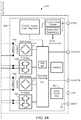
- FIGS. 5A and 5Bare a schematic representation of a signal isolator having a coil/GMR sensing in accordance with example embodiments of the invention.
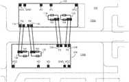
- FIG. 6is a perspective representation of a signal isolator having matching dies on a split leadframe in accordance with example embodiments of the invention.
- FIG. 6Ais a top view of a leadframe for a signal isolator having matching dies on a split leadframe in accordance with example embodiments of the invention
- FIG. 6Bshows a perspective representation of matching dies of a signal isolator on the split leadframe of FIG. 6A ;
- FIG. 7is a schematic representation of a signal isolator coupled to systems that may want to communicate with each other;
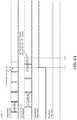
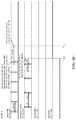
- FIGS. 8A-Fare example waveform diagrams showing fault detection and reporting in accordance with embodiments of the invention.
- FIG. 9is a schematic representation of an example computer that may perform at least a portion of the processing described herein.
- FIG. 1shows an example of a signal isolator 100 including first and second dies 102 , 104 that form part of an integrated circuit package 106 providing signal isolation.
- the IC package 106includes a first input/output (I/O) signal I/OA and a second I/O signal I/OB connected to the first die 102 .
- the IC package 106further includes a third I/O signal I/OC and a fourth I/O signal I/OD connected to the second die 104 .
- the first and second dies 102 , 104are separated by a barrier region 108 , such as a high voltage barrier.
- the first and second I/O signals I/OA,Bare coupled to respective transmit/receive modules 110 , 112 , each of which includes a transmitter 114 , 116 and a receiver 118 , 120 .
- the transmit/receive modules 110 , 112are located on, in, or about the first die 102 .
- the third and fourth I/O signals I/OC,Dare coupled to respective transmit/receive modules 122 , 124 , each of which includes a transmitter 126 , 128 and a receiver 130 , 132 .
- the transmit/receive modules 122 , 124are located on, in, or about the second die 104 .
- the first transmit/receive module 110can function as a transmitter or a receiver.
- the third transmit/receive module 122can function as a transmitter or a receiver.
- the first I/O signal I/OAcan be provided as an input signal to the IC 106 and the third I/O signal I/OC can be provided as an output signal of the IC for communication in a first direction, and vice-versa for communication in the opposite direction.
- an input signal to I/OAcan be received by the IC 106 and output on I/OC with isolation across the barrier region 108 .
- an input signal to I/ODcan be received by the IC 106 and output on I/OB and vice-versa.
- transmit, receive, and transmit/receive modulescan be formed on the first and/or second die to meet the needs of a particular application. It is further understood that transmit, receive, and transmit/receive modules can comprise the same or different components.
- FIG. 2shows an example implementation of the IC 106 in which the first die 102 and the second die 104 are substantially identical and rotated 180 degrees in order to facilitate connections between the transmitters 114 , 116 of the first die 102 and the receivers 130 , 132 of the second die 104 , as well as transmitters 126 , 128 of the second die 104 and receivers 118 , 120 of the first die 102 .
- the pinout (VCC, GND I/Os, VCC) of the IC 106 and transmit and receive moduleswill line up so as to facilitate a series of relatively direct connections, such as wirebonds, between the first and second dies 102 , 104 .
- the first and second die 102 , 104may be identical and rotated 180 degrees from each other, with the correct designation of transmit and receive channels, one can achieve a desired transfer of information to each die with connections nearly straight across the barrier between the dies.
- the IC 106can include a split die paddle in which a leadframe includes a first portion 130 a on which the first die 102 is disposed and a second portion 130 b on which the second die 104 is disposed. It will be appreciated that the first and second portions 130 a,b of the leadframe isolates the first and second dies 102 , 104 . In embodiments, the first and second portions of the leadframe 130 a,b are physically and electrically isolated. In embodiments, separate voltage supply signals and ground connections can be provided to each of the first and second dies 102 , 104 of the IC 106 to promote isolation.
- digital signalscan be provided as inputs to the IC 106 which can generate digital output signals that are isolated to enable systems to communicate with each other via the IC, for example.
- the ground potential connections to the first and second diescan vary by hundreds of volts, for example. Isolation can be provided by capacitive, inductive, and/or coil to magnetic sensing elements for transferring information across the barrier.
- FIG. 3shows one particular implementation of an IC 106 having first and second dies 102 , 104 on separate leadframe portions 130 a,b .
- Polyimide, SiO2 or other insulating layer(s) 140 , 142 for example,can be disposed on the dies 102 , 104 .
- Wirebonds 146can connect the first and second dies 102 , 104 to form the transmit/receive paths across the barrier. In embodiments, the wirebonds go up and down in opposite directions, as shown.
- a diecan be wire-bonded to terminals of a transmitter, such as a coil, which can be driven to create signals that are picked up by a sensing element, such as a GMR.
- a sensing elementsuch as a GMR.
- the left die 102is transmitting to the right die 104 .
- the wire bond 146is oriented to achieve a desired spacing between the wire bond and the edge of the die to mitigate breakdown from the wire-bond to the edge of the die.
- diesare either a receive die or a transmit die, as shown in FIG. 4 , which shows a NVE digital isolator that uses coil to GMR for isolated signal transfer.
- FIG. 4shows a NVE digital isolator that uses coil to GMR for isolated signal transfer.
- Four dieare used to create a device with signals going in both directions.
- the top left and bottom right dieare receiver dies, and the bottom left and top right are transmitter dies.
- FIGS. 5A and 5Bshow an embodiment of an IC package 500 for a signal isolator having matched dies with transmit/receive programmability in accordance with example embodiments of the invention.
- a first power supply input VDD 1provides power to a first die 502 and a second power supply input VDD 2 provides power to a second die 504 .
- a first ground pin GND 1provides a ground reference for the first die 502 and a second ground pin GND 2 provides a ground references for the second die 504 .
- the ground pins GND 1 , GND 2are isolated from each other.
- Signal pinsinclude IN/OUTA and OUT/INB connected to the first die 502 and OUT/INA and IN/OUTB connected to the second die 504 .
- each of IN/OUTA OUT/INB, OUT/INA and IN/OUTBcan be programmed as an input or output signal.
- these signalsmay be programmed in pairs to provide a signal path through the barrier region 508 between the first and second dies 502 , 504 .
- the first die 502can include a first encoding/decoding module 510 coupled to signal pins include IN/OUTA and OUT/INB and the second die 504 can include a second encoding/decoding module 511 coupled to signal pins include OUT/INA and IN/OUTB.
- the first die 502includes a first transmitter 512 that can be provided as a transistor bridge circuit coupled to the first encoding/decoding module 510 .
- the first die 502can further include a second transmitter 514 .
- the first dieincludes a first receiver 516 that can be provided as a sensing element, such as a magnetic sensing element, which is shown as a GMR bridge.
- the first die 502can further include a second receiver 518 .
- the second die 504includes a third transmitter 520 that can be provided as a transistor bridge circuit coupled to the second encoding/decoding module 511 .
- the second die 504can further include a fourth transmitter 522 .
- the second die 504includes a third receiver 524 that can be provided as a sensing element, such as a GMR bridge.
- the first diecan further include a fourth receiver 526 .
- the first die 502includes a first coil 530 positioned in relation to the first GMR bridge 516 to detect signal information from the coil 530 and a second coil 532 for the second GMR bridge.
- the second die 504can include coils 534 , 536 for respective bridges 524 , 526 on the die for detecting signals from transmitters 512 , 514 on the first die 502 .
- the coil 530is energized by the first transmitter 520 of the second die 504 and sensed by the GMR bridge 516 .
- an input signal received on OUT/INAis received and provided to transmitter 520 in accordance with a path configuration of the second encoding/decoding module 511 .
- the transmitter 520energizes the coil 530 on the first die 502 for sensing by bridge 516 .
- the sensed signalis provided to the IN/OUTA pin of the IC 500 .
- the first and second encoding/decoding modules 510 , 511selectively configure a path between one of IN/OUTA and OUT/INB for the first die 502 and one of OUT/INA and IN/OUTB for the second die 504 .
- the programmability of the pathsenables each of IN/OUTA, OUT/INB, OUT/INA and IN/OUTB to be an input signal or an output signal with desired signal isolation.
- the first and second encoding/decoding modules 510 , 511can each include a respective diagnostic module 560 , 561 for generating refresh signals, such as pulses between transmit and receive paths, as described more fully below.
- transmitter 512 , coil 534 , and sensing element 524 , and transmitter 520 , coil 530 and sensing element 516can provide bi-directional communication between the first and second die for feedback and diagnostic signals, as described below.
- FIG. 6shows a schematic representation of first and second die 602 , 604 on a split leadframe having isolated first and second portions 606 , 608 with wirebonds 610 providing transmit/receive paths between the dies and power/ground connections.
- the first and second die 602 , 604are substantially identical and rotated 180 degrees with respect to each other to facilitate the transmitter-receiver wirebond connections between the first and second dies.
- Embodiments of the inventionmay allow for a single die configuration to be used to provide isolated transmitter-receiver channels between first and second dies housed in a single IC package. With this arrangement, a single die design can be developed, produced, and tested to simplify and lower the cost of the process and the supply chain. In contrast to conventional isolator ICs that require multiple die designs, embodiments of the invention may utilize two substantially identical die for a bidirectional isolator IC package.
- wire bondscan be connected across a barrier between first and second die to enable selection of a direction of each channel through programming, such as during final test. This simplifies the supply chain since all of the versions of the IC package may be the same up until final test.
- directionalitycan be determined during assembly, for example by the wire bonds.
- pull up/down wire-bondingcan be used to program the devices instead of configuration data in non-volatile memory, for example.
- bi-directionality on each channelallows for hand-shaking and error checking as data is transmitted and received.
- a transmittercan receive information from a receiver that data is being received.
- conventional isolatorssuch as optical isolators, do not allow for a receiver to send information to the transmitter.
- FIG. 6Ashows an example split leadframe 650 having isolated first and second portions 652 a,b and FIG. 6B shows the split leadframe 650 having matched first and dies 654 a,b disposed on the respective first and second leadframe portions 652 a,b .
- the first portion 652 a of the leadframecan include dimples 656 in an array configuration.
- the dimple arrayis a 3 ⁇ 6 array. It is understood that dimples 656 comprise a protrusion of some sort above the planar surface of the leadframe to mitigate delamination of the die from the leadframe. It is further understood that the array can include columns and rows of dimples, a random distribution of dimples, and/or a combination thereof.
- pin numbersare shown from pin 1 in the top right to pin 16 in the bottom right.
- pins 2 , 8 , 9 , and 15are configured for connection to ground.
- pins 2 and 8form one ground that is different from another ground formed by pins 9 and 16
- the leadframe portionscan include respective tails 658 a, b to enhance clamping during wirebonding 662 to the leadframe fingers.
- one or more anchor holes 660can be stamped or etched in one or more pins to facilitate mold adhesion on floating leads, for example.
- FIG. 6Bshows connections 664 between transmitters and receivers on the respective dies 654 a,b as shown and described above.
- FIG. 7shows an example isolator 700 IC in accordance with illustrative embodiments coupled to first, second, third, and fourth systems S 1 , S 2 . S 3 , S 4 .
- the first system S 1can transmit and receive data with the second system S 2 and the third system S 3 can communicate with the fourth system S 4 .
- the first system S 1can communicate with the fourth system S 4 with control of the data paths by the first and second encoding/decoding modules 510 , 511 ( FIG. 5 ).
- the third system S 3can communicate with the second system S 2 and/or fourth system S 4 .
- the second system S 2can communicate with the first and/or third systems S 1 , S 3
- the fourth system S 4can communicate with the first and/or third systems S 1 , S 3
- a systemcan communicate with one or more systems coupled across the barrier via first and second dies.
- a signal isolatorincludes diagnostic functionality to determine if signals are transferring correctly.
- an internal return communication channel on a unidirectional external communication channelcan be used for implementing diagnostics to determine if signals are transferring correctly. Diagnostic results may be provided to systems coupled to the isolation IC package on each side the isolation barrier.
- an isolator IC packagecan include a data valid pin associated with each of the first and second dies to provide diagnostic results indicating whether data was successfully transferred over the channels.
- a diagnostic failurecan be communicated via one of the communication channels on one or both sides of the barrier.
- a diagnostic failurecan cause the signal isolator to enter a pre-determined state, such as data transmission/reception stoppage. Output(s) may enter a predetermined state or signal level or become high-impedance.
- first and second data valid pads 550 , 552may be provided for the respective first and second dies 502 , 504 .
- Data valid signalscan be provided as pins DVA and DVB on the IC package and controlled by the respective first and second encoding/decoding modules 510 , 511 , which can monitor transmit and receive signal, as described more fully below.
- each channel between the first and second diesthere is a driver, coil, and GMR signal path in each direction.
- channel A(upper channel) may transfer information from left to right, such that bridge 512 to coil 534 to GMR 524 can be used for signal transfer.
- the path of bridge 520 to coil 530 to GMR 516 for channel A(the lower path for channel A), provides data flow in the opposite direction for enabling a receiver to indicate to the transmitter that the message was received.
- Similar upper and lower pathscan be formed for channel B to enable bi-directional data flow.
- the receivercan indicate that the message was received and/or echo the message back and/or periodically indicate that messages are being received.
- the transmitter and receivercan both determine that communications are flowing between the first and second die.
- the status of the data flows for the upper and lower channel Ais indicated with the respective data valid pins DVA, DVB. In this way, the systems on both sides of the isolation barrier are able to know whether the information they are sending is being received and/or whether information is being sent.
- signal edgesare transmitted across the barrier between the first and second dies.
- a pulse of currentis injected in the coil in the direction of change in order to indicate this change to the receiver. For example, a high to low transition results in a negative pulse of current.
- the transmitterrepeats the last transition at a fixed interval Trefresh if there is no change on the input.
- the receiversends a similar refresh pulse. In example embodiments, every 1.5*Trefresh, as long as the receiver has received a pulse from the transmitter, the receiver issues a pulse to the transmitter. The receiver issues a positive pulse if its output is high and a negative pulse if its output is low.
- receiver and transmitter refresh signals and example times and edgesare monitored to determine the health of the transmit and receive paths between the die. It is understood that a wide range of signal types, characteristics, timing, durations, etc., can be used to monitors signals along the transmit and receive paths without departing from the scope of the invention.
- the receiverconstantly reflects received pulses back to the transmitter to allow for fast checking of the communication, as well as bit by bit correctness.
- the receivermay de-assert its data valid pin to indicate to the system on that side that the receiver has stopped receiving information from the transmitter.
- the transmitterde-asserts its data valid pin, indicating to the system on that side that the information being sent is no longer being received.
- the transmittercan also slow its refresh pulses to 3*Trefresh, for example.
- the transmittermay stop transmitting pulses on that channel and de-assert its data valid pin.
- the ICmay stop sending pulses across the barrier and de-assert its data valid pin.
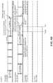
- FIG. 8Ashows an example waveform in which refresh pulses are generated by a transmitter with an edge at a given intervals t_refresh and receiver refresh pulses are generated at intervals of 1.5*t_refresh.
- a transmitter data valid signal and a receiver data valid signalare initially at a level corresponding to valid data while the data and refresh pulses are being timely transmitted.
- a transmittermay refer to a signal source, such as bridge 512 in FIG. 5 , which may include coil 534
- a receivermay refer to a sensing element, such as sensing element 524 in FIG. 5 , which is coupled to coil 534 .
- datamay go in one direction from a transmitter to a receiver and refresh/diagnostic signals flow in both directions.
- refresh signalsare transmitted by a transmitter when there is no data to be transmitted to the receiver.
- the transmitterloses power causing the transmitter data valid signal to transition indicating that data is no longer valid. Refresh pulses cease being transmitted and nothing is transmitted to the receiver.
- time t TRLwhich is 1.5*Trefresh from the last transmitter refresh pulse edge, the receiver de-asserts its data-valid pin.
- FIG. 8Bshows the same signals as FIG. 8A when the receiver loses power or enable pin is logic low at time t RPL : In this case, the transmitter will not receive any return pulses from the receiver. After time 2*Trefresh, for example, from the last receiver refresh pulse edge, the transmitter de-asserts its data-valid pin at time t RRL . The transmitter may also slow down its refresh pulses to 3*t_refresh but continue to issue them, in order to recover in the case that the receiver regains power.
- FIG. 8Cshows waveforms corresponding to broken transmit/receive circuitry on the forward path (e.g., wire bond breaks, GMR breaks, etc. . . . ):
- the transmitteris not aware that the transmitted pulses are not being received.
- the receiverdoes not receive any information.
- time t BRKwhich corresponds to 1.5*Trefresh, for example, from the last transmitter refresh pulse edge, the receiver de-asserts its data-valid pin.
- the receiverdoes not send any reverse refresh pulses, so that the transmitter de-asserts its data-valid pin at time t DA and slows down its refresh rate.
- a reverse pulsemay refer to a situation in which the receiver is looking for refresh pulses every Trefresh, and the transmitter is looking for refresh pulses (reverse refresh pulse) every 2*Trefresh, for example. If the transmitter does not see a reverse pulse, for example, it is determined that the receiver is having problems.
- FIG. 8Dshows waveforms corresponding to a break in the transmit/receive circuitry on the reverse path (e.g., wire bond breaks, GMR breaks, etc.).
- the receiveris receiving the correct information, but the receiver is not able to provide an indication of this to the transmitter.
- the transmitterwill not receive any reverse pulses, so it will de-assert its data-valid pin at time t RBRK and start sending pulses at 3*Trefresh, for example. In this way, the receiver will then time-out on the other side and de-assert its data-valid pin at time t RDA .
- FIG. 8Eshows waveforms corresponding to the transmitter input not being driven.
- the transmitterdetects this situation at time tip, stops sending refresh pulses across the barrier, and de-asserts its data valid pin.
- the receiverdoes not see any transmitter refresh pulses and de-asserts its data valid pin at time t RDA , which can correspond to 1.5*t_refresh from the edge of the last transmitter refresh pulse.
- the waveformscan also correspond to a failure of built-in-self-test (BIST) of the transmitter.
- BISTbuilt-in-self-test
- the transmitterstops sending pulses and de-asserts its data valid pin.
- the receiverwill not see any pulses and de-asserts its data valid pin.
- FIG. 8Fshows waveforms corresponding to BIST failure on the receiver.
- the receiverdetects a problem at time t RDB and stops sending refresh pulses and de-asserts its data valid pin.
- the transmitterstops seeing pulses in return and de-assert its data valid pin at time t TDA , which can correspond to 2*t_refresh since the edge of the last receiver refresh pulse.
- the transmittermay also slow down its refresh pulses until it sees a return pulse.
- magnetic field sensing elementis used to describe a variety of electronic elements that can sense a magnetic field.
- the magnetic field sensing elementcan comprise, but is not limited to, a Hall Effect element, a magnetoresistance element, and/or a magnetotransistor.
- Hall Effect elementsfor example, a planar Hall element, a vertical Hall element, and a Circular Vertical Hall (CVH) element.
- magnetoresistance elementsfor example, a semiconductor magnetoresistance element such as Indium Antimonide (InSb), a giant magnetoresistance (GMR) element, for example, a spin valve, an anisotropic magnetoresistance element (AMR), a tunneling magnetoresistance (TMR) element, a magnetic tunnel junction (MTJ), and a spin-valve.
- the magnetic field sensing elementmay be a single element or, alternatively, may include two or more magnetic field sensing elements arranged in various configurations, e.g., a half bridge or full (Wheatstone) bridge.
- the magnetic field sensing elementmay be a device made of a type IV semiconductor material such as Silicon (Si) or Germanium (Ge), or a type III-V semiconductor material like Gallium-Arsenide (GaAs) or an Indium compound, e.g., Indium-Antimonide (InSb).
- a type IV semiconductor materialsuch as Silicon (Si) or Germanium (Ge)
- a type III-V semiconductor materiallike Gallium-Arsenide (GaAs) or an Indium compound, e.g., Indium-Antimonide (InSb).
- some of the above-described magnetic field sensing elementstend to have an axis of maximum sensitivity parallel to a substrate that supports the magnetic field sensing element, and others of the above-described magnetic field sensing elements tend to have an axis of maximum sensitivity perpendicular to a substrate that supports the magnetic field sensing element.
- planar Hall elementstend to have axes of sensitivity perpendicular to a substrate
- metal based or metallic magnetoresistance elementse.g., GMR, TMR, AMR
- vertical Hall elementstend to have axes of sensitivity parallel to a substrate.
- magnetic field sensoris used to describe a circuit that uses a magnetic field sensing element, generally in combination with other circuits.
- Magnetic field sensorsare used in a variety of applications, including, but not limited to, an angle sensor that senses an angle of a direction of a magnetic field, a current sensor that senses a magnetic field generated by a current carried by a current-carrying conductor, a magnetic switch that senses the proximity of a ferromagnetic object, a rotation detector that senses passing ferromagnetic articles, for example, magnetic domains of a ring magnet or a ferromagnetic target (e.g., gear teeth) where the magnetic field sensor is used in combination with a back-biased or other magnet, and a magnetic field sensor that senses a magnetic field density of a magnetic field.
- an angle sensorthat senses an angle of a direction of a magnetic field
- a current sensorthat senses a magnetic field generated by a current carried by a current-carrying conductor
- a magnetic switchthat
- FIG. 9shows an exemplary computer 900 that can perform at least part of the processing described herein.
- the computer 900includes a processor 902 , a volatile memory 904 , a non-volatile memory 906 (e.g., hard disk), an output device 907 and a graphical user interface (GUI) 908 (e.g., a mouse, a keyboard, a display, for example).
- the non-volatile memory 906stores computer instructions 912 , an operating system 916 and data 918 .
- the computer instructions 912are executed by the processor 902 out of volatile memory 904 .
- an article 920comprises non-transitory computer-readable instructions.
- Processingmay be implemented in hardware, software, or a combination of the two. Processing may be implemented in computer programs executed on programmable computers/machines that each includes a processor, a storage medium or other article of manufacture that is readable by the processor (including volatile and non-volatile memory and/or storage elements), at least one input device, and one or more output devices. Program code may be applied to data entered using an input device to perform processing and to generate output information.
- the systemcan perform processing, at least in part, via a computer program product, (e.g., in a machine-readable storage device), for execution by, or to control the operation of, data processing apparatus (e.g., a programmable processor, a computer, or multiple computers).
- a computer program producte.g., in a machine-readable storage device
- data processing apparatuse.g., a programmable processor, a computer, or multiple computers.
- Each such programmay be implemented in a high level procedural or object-oriented programming language to communicate with a computer system.
- the programsmay be implemented in assembly or machine language.
- the languagemay be a compiled or an interpreted language and it may be deployed in any form, including as a stand-alone program or as a module, component, subroutine, or other unit suitable for use in a computing environment.
- a computer programmay be deployed to be executed on one computer or on multiple computers at one site or distributed across multiple sites and interconnected by a communication network.
- a computer programmay be stored on a storage medium or device (e.g., CD-ROM, hard disk, or magnetic diskette) that is readable by a general or special purpose programmable computer for configuring and operating the computer when the storage medium or device is read by the computer.
- Processingmay also be implemented as a machine-readable storage medium, configured with a computer program, where upon execution, instructions in the computer program cause the computer to operate.
- Processingmay be performed by one or more programmable processors executing one or more computer programs to perform the functions of the system. All or part of the system may be implemented as, special purpose logic circuitry (e.g., an FPGA (field programmable gate array) and/or an ASIC (application-specific integrated circuit)).
- special purpose logic circuitrye.g., an FPGA (field programmable gate array) and/or an ASIC (application-specific integrated circuit)
Landscapes
- Engineering & Computer Science (AREA)
- Computer Networks & Wireless Communication (AREA)
- Signal Processing (AREA)
- Physics & Mathematics (AREA)
- Power Engineering (AREA)
- Electromagnetism (AREA)
- Microelectronics & Electronic Packaging (AREA)
- Condensed Matter Physics & Semiconductors (AREA)
- General Physics & Mathematics (AREA)
- Computer Hardware Design (AREA)
- Semiconductor Integrated Circuits (AREA)
- Near-Field Transmission Systems (AREA)
Abstract
Description
Claims (59)
Priority Applications (1)
| Application Number | Priority Date | Filing Date | Title |
|---|---|---|---|
| US15/702,937US10651147B2 (en) | 2016-09-13 | 2017-09-13 | Signal isolator having bidirectional communication between die |
Applications Claiming Priority (2)
| Application Number | Priority Date | Filing Date | Title |
|---|---|---|---|
| US201662393805P | 2016-09-13 | 2016-09-13 | |
| US15/702,937US10651147B2 (en) | 2016-09-13 | 2017-09-13 | Signal isolator having bidirectional communication between die |
Publications (2)
| Publication Number | Publication Date |
|---|---|
| US20180076176A1 US20180076176A1 (en) | 2018-03-15 |
| US10651147B2true US10651147B2 (en) | 2020-05-12 |
Family
ID=59997052
Family Applications (2)
| Application Number | Title | Priority Date | Filing Date |
|---|---|---|---|
| US15/702,937ActiveUS10651147B2 (en) | 2016-09-13 | 2017-09-13 | Signal isolator having bidirectional communication between die |
| US15/702,940ActiveUS10290608B2 (en) | 2016-09-13 | 2017-09-13 | Signal isolator having bidirectional diagnostic signal exchange |
Family Applications After (1)
| Application Number | Title | Priority Date | Filing Date |
|---|---|---|---|
| US15/702,940ActiveUS10290608B2 (en) | 2016-09-13 | 2017-09-13 | Signal isolator having bidirectional diagnostic signal exchange |
Country Status (2)
| Country | Link |
|---|---|
| US (2) | US10651147B2 (en) |
| EP (2) | EP3293888B1 (en) |
Cited By (4)
| Publication number | Priority date | Publication date | Assignee | Title |
|---|---|---|---|---|
| US11326903B1 (en) | 2020-11-13 | 2022-05-10 | Allegro Microsystems, Llc | Rotary inductive sensor |
| US11460286B2 (en) | 2020-11-13 | 2022-10-04 | Allegro Microsystems, Llc | Rotary inductive sensor |
| US12107710B2 (en) | 2020-11-19 | 2024-10-01 | Allegro Microsystems, Llc | Sensor signaling of absolute and incremental data |
| US12104900B2 (en) | 2022-09-29 | 2024-10-01 | Allegro Microsystems, Llc | Sensor with estimated real-time parameter data |
Families Citing this family (22)
| Publication number | Priority date | Publication date | Assignee | Title |
|---|---|---|---|---|
| US10488456B2 (en)* | 2017-05-31 | 2019-11-26 | Silicon Laboratories Inc. | Test interface with access across isolation barrier |
| US10236932B1 (en)* | 2017-11-02 | 2019-03-19 | Allegro Microsystems, Llc | Signal isolator having magnetic signal latching |
| US10816597B2 (en) | 2017-12-08 | 2020-10-27 | Silicon Laboratories Inc. | Single pin test interface for pin limited systems |
| US11199424B2 (en) | 2018-01-31 | 2021-12-14 | Allegro Microsystems, Llc | Reducing angle error in a magnetic field angle sensor |
| US10753968B2 (en) | 2018-02-27 | 2020-08-25 | Allegro Microsystems, Llc | Integrated circuit having insulation breakdown detection |
| US11115084B2 (en) | 2018-11-27 | 2021-09-07 | Allegro Microsystems, Llc | Isolated data transfer system |
| US11112465B2 (en) | 2019-02-05 | 2021-09-07 | Allegro Microsystems, Llc | Integrated circuit having insulation monitoring with frequency discrimination |
| JP7338204B2 (en)* | 2019-04-01 | 2023-09-05 | 富士電機株式会社 | semiconductor equipment |
| US11152288B2 (en)* | 2019-04-25 | 2021-10-19 | Infineon Technologies Ag | Lead frames for semiconductor packages |
| US20210057330A1 (en)* | 2019-08-22 | 2021-02-25 | Allegro Microsystems, Llc | Single chip signal isolator |
| US11175359B2 (en) | 2019-08-28 | 2021-11-16 | Allegro Microsystems, Llc | Reducing voltage non-linearity in a bridge having tunneling magnetoresistance (TMR) elements |
| US11115244B2 (en) | 2019-09-17 | 2021-09-07 | Allegro Microsystems, Llc | Signal isolator with three state data transmission |
| US11024576B1 (en)* | 2019-12-31 | 2021-06-01 | Texas Instruments Incorporated | Semiconductor package with underfill between a sensor coil and a semiconductor die |
| US11467233B2 (en) | 2020-03-18 | 2022-10-11 | Allegro Microsystems, Llc | Linear bridges having nonlinear elements |
| US11408948B2 (en) | 2020-03-18 | 2022-08-09 | Allegro Microsystems, Llc | Linear bridge having nonlinear elements for operation in high magnetic field intensities |
| JP7527916B2 (en)* | 2020-09-29 | 2024-08-05 | ローム株式会社 | Semiconductor Device |
| US11515246B2 (en) | 2020-10-09 | 2022-11-29 | Allegro Microsystems, Llc | Dual circuit digital isolator |
| CN113097082B (en)* | 2021-03-31 | 2023-05-16 | 重庆线易电子科技有限责任公司 | Welding method for digital isolator and bonding wire |
| CN113358137B (en)* | 2021-06-04 | 2023-03-03 | 蚌埠希磁科技有限公司 | Magnetism resistance module and magnetic sensor |
| US11630169B1 (en) | 2022-01-17 | 2023-04-18 | Allegro Microsystems, Llc | Fabricating a coil above and below a magnetoresistance element |
| US11782105B2 (en) | 2022-01-17 | 2023-10-10 | Allegro Microsystems, Llc | Fabricating planarized coil layer in contact with magnetoresistance element |
| US12364163B2 (en) | 2022-08-30 | 2025-07-15 | Allegro Microsystems, Llc | Fabricating an electroconductive contact on a top layer of a tunneling magnetoresistance element using two hard masks |
Citations (190)
| Publication number | Priority date | Publication date | Assignee | Title |
|---|---|---|---|---|
| US3058078A (en) | 1956-02-21 | 1962-10-09 | Siegfried R Hoh | Low capacitance transformer |
| US3537022A (en) | 1968-01-10 | 1970-10-27 | Hewlett Packard Co | Signal translating circuit |
| US3713148A (en) | 1970-05-21 | 1973-01-23 | Communications Services Corp I | Transponder apparatus and system |
| US3714540A (en) | 1970-11-10 | 1973-01-30 | Oxy Metal Finishing Corp | Isolation and transforming circuit |
| US3760198A (en) | 1970-11-06 | 1973-09-18 | Yokogawa Electric Works Ltd | Circuitry for transmitting pulses with ground isolation but without pulse waveform distortion |
| US3798608A (en) | 1972-12-15 | 1974-03-19 | Johnson Service Co | Digital signal transmission apparatus |
| US3859624A (en) | 1972-09-05 | 1975-01-07 | Thomas A Kriofsky | Inductively coupled transmitter-responder arrangement |
| US4024452A (en) | 1976-03-10 | 1977-05-17 | Bell Telephone Laboratories, Incorporated | Integrated solid state isolator circuit |
| US4027152A (en) | 1975-11-28 | 1977-05-31 | Hewlett-Packard Company | Apparatus and method for transmitting binary-coded information |
| US4118603A (en) | 1977-05-31 | 1978-10-03 | Noramco, Inc. | DC signaling circuit for use in conjunction with isolation transformers |
| US4188927A (en) | 1978-01-12 | 1980-02-19 | Valleylab, Inc. | Multiple source electrosurgical generator |
| US4227045A (en) | 1978-06-28 | 1980-10-07 | Honeywell Inc. | Data processing protocol system |
| US4302807A (en) | 1980-08-04 | 1981-11-24 | Burroughs Corporation | Controlled current base drive circuit |
| JPS57123460A (en) | 1981-01-23 | 1982-07-31 | Hitachi Ltd | Hardware monitor system |
| US4360784A (en) | 1980-08-13 | 1982-11-23 | Automation Systems, Inc. | Transformer coupled isolation amplifier |
| US4425647A (en) | 1979-07-12 | 1984-01-10 | Zenith Radio Corporation | IR Remote control system |
| US4459591A (en) | 1981-02-05 | 1984-07-10 | Robert Bosch Gmbh | Remote-control operating system and method for selectively addressing code-addressable receivers, particularly to execute switching function in automotive vehicles |
| US4526128A (en) | 1984-02-13 | 1985-07-02 | Advanced Tech Tool, Ltd. | High-speed indexing feed screw conveyer |
| US4538136A (en) | 1981-03-30 | 1985-08-27 | Amtel Systems Corporation | Power line communication system utilizing a local oscillator |
| US4547961A (en) | 1980-11-14 | 1985-10-22 | Analog Devices, Incorporated | Method of manufacture of miniaturized transformer |
| GB2173956A (en) | 1985-03-29 | 1986-10-22 | Plessey Co Plc | Integrated electrical transformer |
| US4650981A (en) | 1984-01-26 | 1987-03-17 | Foletta Wayne S | Credit card with active electronics |
| US4660014A (en) | 1985-06-19 | 1987-04-21 | Jaycor | Electromagnetic pulse isolation transformer |
| US4675579A (en) | 1985-03-18 | 1987-06-23 | General Electric Company | Coupling of carrier signal from power line |
| US4703283A (en) | 1986-02-24 | 1987-10-27 | Howard Samuels | Isolation amplifier with T-type modulator |
| US4748419A (en) | 1986-04-28 | 1988-05-31 | Burr-Brown Corporation | Isolation amplifier with precise timing of signals coupled across isolation barrier |
| US4763075A (en) | 1984-08-20 | 1988-08-09 | Siemens Aktiengesellschaft | Electro-optical isolator for magnetic resonance tomography |
| US4780795A (en) | 1986-04-28 | 1988-10-25 | Burr-Brown Corporation | Packages for hybrid integrated circuit high voltage isolation amplifiers and method of manufacture |
| US4785345A (en) | 1986-05-08 | 1988-11-15 | American Telephone And Telegraph Co., At&T Bell Labs. | Integrated transformer structure with primary winding in substrate |
| US4791326A (en) | 1987-01-22 | 1988-12-13 | Intel Corporation | Current controlled solid state switch |
| US4818855A (en) | 1985-01-11 | 1989-04-04 | Indala Corporation | Identification system |
| US4817865A (en) | 1988-03-17 | 1989-04-04 | Racal Data Communications Inc. | Ventilation system for modular electronic housing |
| US4825450A (en) | 1987-03-12 | 1989-04-25 | The Boeing Company | Binary data communication system |
| US4835486A (en) | 1986-04-28 | 1989-05-30 | Burr-Brown Corporation | Isolation amplifier with precise timing of signals coupled across isolation barrier |
| US4853654A (en) | 1986-07-17 | 1989-08-01 | Kabushiki Kaisha Toshiba | MOS semiconductor circuit |
| US4859877A (en) | 1988-01-04 | 1989-08-22 | Gte Laboratories Incorporated | Bidirectional digital signal transmission system |
| US4864437A (en) | 1988-03-07 | 1989-09-05 | Syquest Technology | Head loading velocity control |
| US4868647A (en) | 1987-09-14 | 1989-09-19 | Olympus Optical Co., Ltd. | Electronic endoscopic apparatus isolated by differential type drive means |
| US4885582A (en) | 1987-09-28 | 1989-12-05 | The Grass Valley Group, Inc. | "Simple code" encoder/decoder |
| US4922883A (en) | 1987-10-29 | 1990-05-08 | Aisin Seiki Kabushiki Kaisha | Multi spark ignition system |
| US4924210A (en) | 1987-03-17 | 1990-05-08 | Omron Tateisi Electronics Company | Method of controlling communication in an ID system |
| US4931867A (en) | 1988-03-01 | 1990-06-05 | Olympus Optical Co., Ltd. | Electronic endoscope apparatus having an isolation circuit for isolating a patient circuit from a secondary circuit |
| US4937468A (en) | 1989-01-09 | 1990-06-26 | Sundstrand Corporation | Isolation circuit for pulse waveforms |
| US4945264A (en) | 1989-01-05 | 1990-07-31 | Acer Incorporated | Interface control circuit with active circuit charge or discharge |
| US4959631A (en) | 1987-09-29 | 1990-09-25 | Kabushiki Kaisha Toshiba | Planar inductor |
| US5041780A (en) | 1988-09-13 | 1991-08-20 | California Institute Of Technology | Integrable current sensors |
| US5057968A (en) | 1989-10-16 | 1991-10-15 | Lockheed Corporation | Cooling system for electronic modules |
| US5095357A (en) | 1989-08-18 | 1992-03-10 | Mitsubishi Denki Kabushiki Kaisha | Inductive structures for semiconductor integrated circuits |
| US5102040A (en) | 1991-03-28 | 1992-04-07 | At&T Bell Laboratories | Method and apparatus for fan control to achieve enhanced cooling |
| US5125111A (en) | 1990-09-04 | 1992-06-23 | Rockwell International Corporation | Resistive planar ring double-balanced mixer |
| US5142432A (en) | 1991-10-21 | 1992-08-25 | General Motors Corporation | Fault detection apparatus for a transformer isolated transistor drive circuit for a power device |
| US5164621A (en) | 1990-11-06 | 1992-11-17 | Mitsubishi Denki Kabushiki Kaisha | Delay device including generator compensating for power supply fluctuations |
| US5168863A (en) | 1990-08-27 | 1992-12-08 | Medical Concepts, Inc. | Sterile endoscopic system |
| FR2679670A1 (en) | 1991-07-23 | 1993-01-29 | Serbanescu Dan | System of contactless two-way communication for microprocessor-based credit cards |
| US5204551A (en) | 1991-07-01 | 1993-04-20 | Motorola, Inc. | Method and apparatus for high power pulse modulation |
| US5270882A (en) | 1992-07-15 | 1993-12-14 | International Business Machines Corporation | Low-voltage, low-power amplifier for magnetoresistive sensor |
| US5293400A (en) | 1990-05-18 | 1994-03-08 | Centre National Du Machinisme Agricole, Du Genie Rural, Des Eaux Et Des Forets | Contactless linking device for interconnecting data bus sections |
| US5369666A (en) | 1992-06-09 | 1994-11-29 | Rockwell International Corporation | Modem with digital isolation |
| US5384808A (en) | 1992-12-31 | 1995-01-24 | Apple Computer, Inc. | Method and apparatus for transmitting NRZ data signals across an isolation barrier disposed in an interface between adjacent devices on a bus |
| US5396394A (en) | 1990-02-06 | 1995-03-07 | International Business Machines Corp. | ISDN device line protection circuit |
| US5404545A (en) | 1992-07-29 | 1995-04-04 | Hewlett-Packard Company | Interface isolation and selection circuit for a local area network |
| JPH0744515B2 (en) | 1990-05-31 | 1995-05-15 | 日本電気株式会社 | Interference wave removal method |
| US5418933A (en) | 1990-02-20 | 1995-05-23 | Sharp Kabushiki Kaisha | Bidirectional tri-state data bus buffer control circuit for delaying direction switching at I/O pins of semiconductor integrated circuit |
| US5424709A (en) | 1988-06-17 | 1995-06-13 | Ixys Corporation | Circuit for providing isolation between components of a power control system and for communicating power and data through the isolation media |
| US5442303A (en) | 1992-07-16 | 1995-08-15 | The Nippon Signal Co., Ltd. | Electromagnetically coupled fail-safe logic circuit |
| US5444740A (en) | 1992-09-18 | 1995-08-22 | Hitachi, Ltd. | A ternary signal transmission circuit and method |
| US5448469A (en) | 1990-02-15 | 1995-09-05 | Deutsche Thomson-Brandt Gmbh | Switch mode power supply with output feedback isolation |
| US5469098A (en) | 1993-03-29 | 1995-11-21 | Exide Electronics Corporation | Isolated gate drive |
| US5467607A (en) | 1994-02-22 | 1995-11-21 | At&T Corp. | Air conditioning control system |
| US5484012A (en) | 1994-03-15 | 1996-01-16 | Fujitsu Limited | Electronic apparatus having cooling system |
| US5533054A (en) | 1993-07-09 | 1996-07-02 | Technitrol, Inc. | Multi-level data transmitter |
| US5539598A (en) | 1994-12-08 | 1996-07-23 | International Business Machines Corporation | Electrostatic protection for a shielded MR sensor |
| US5555421A (en) | 1993-11-23 | 1996-09-10 | Kistler Instrument Company | Bidirectional interface for interconnecting two devices and the interface having first optical isolator and second optical isolator being powered by first and second device ports |
| US5568333A (en) | 1994-06-20 | 1996-10-22 | Samsung Electronics Co., Ltd. | Actuator latching device of hard disk drive |
| US5572179A (en) | 1992-05-27 | 1996-11-05 | Fuji Electric Co., Ltd. | Thin film transformer |
| US5588021A (en) | 1992-09-25 | 1996-12-24 | Light & Sound Design Limited | Repeater for use in a control network |
| US5591996A (en) | 1995-03-24 | 1997-01-07 | Analog Devices, Inc. | Recirculating charge transfer magnetic field sensor |
| US5596466A (en) | 1995-01-13 | 1997-01-21 | Ixys Corporation | Intelligent, isolated half-bridge power module |
| US5615091A (en) | 1995-10-11 | 1997-03-25 | Biochem International, Inc. | Isolation transformer for medical equipment |
| US5615229A (en) | 1993-07-02 | 1997-03-25 | Phonic Ear, Incorporated | Short range inductively coupled communication system employing time variant modulation |
| US5625265A (en) | 1995-06-07 | 1997-04-29 | Kollmorgen Corporation | Compact, high efficiency electronic motor controller with isolated gate drive for power transistors |
| US5627488A (en) | 1994-06-23 | 1997-05-06 | Kabushiki Kaisha Toshiba | Delay circuit, oscillation circuit and semiconductor memory device |
| US5627480A (en) | 1996-02-08 | 1997-05-06 | Xilinx, Inc. | Tristatable bidirectional buffer for tristate bus lines |
| US5650357A (en) | 1992-12-03 | 1997-07-22 | Linear Technology Corporation | Process for manufacturing a lead frame capacitor and capacitively-coupled isolator circuit using same |
| US5654984A (en) | 1993-12-03 | 1997-08-05 | Silicon Systems, Inc. | Signal modulation across capacitors |
| US5663672A (en) | 1995-11-17 | 1997-09-02 | Sundstrand Corporation | Transistor gate drive circuit providing dielectric isolation and protection |
| US5701037A (en) | 1994-11-15 | 1997-12-23 | Siemens Aktiengesellschaft | Arrangement for inductive signal transmission between the chip layers of a vertically integrated circuit |
| US5714938A (en) | 1996-11-19 | 1998-02-03 | Cae Electronics Ltd. | Temperature protection device for air cooled electronics housing |
| US5716323A (en) | 1995-04-05 | 1998-02-10 | Karl Storz Imaging | Electrical isolation of endoscopic video camera |
| US5731727A (en) | 1994-11-01 | 1998-03-24 | Mitsubishi Denki Kabushiki Kaisha | Voltage control type delay circuit and internal clock generation circuit using the same |
| US5731954A (en) | 1996-08-22 | 1998-03-24 | Cheon; Kioan | Cooling system for computer |
| US5774791A (en) | 1993-07-02 | 1998-06-30 | Phonic Ear Incorporated | Low power wireless communication system employing magnetic control zones |
| US5781077A (en) | 1997-01-28 | 1998-07-14 | Burr-Brown Corporation | Reducing transformer interwinding capacitance |
| US5781071A (en) | 1994-12-17 | 1998-07-14 | Sony Corporation | Transformers and amplifiers |
| US5786763A (en) | 1996-06-20 | 1998-07-28 | Sensormatic Electronics Corporation | Antenna multiplexer with isolation of switching elements |
| US5786979A (en) | 1995-12-18 | 1998-07-28 | Douglass; Barry G. | High density inter-chip connections by electromagnetic coupling |
| US5801602A (en) | 1996-04-30 | 1998-09-01 | 3Com Corporation | Isolation and signal filter transformer |
| US5812597A (en) | 1994-09-21 | 1998-09-22 | Tut Systems, Inc. | Circuit for preventing base line wander of digital signals in a network receiver |
| US5825259A (en) | 1994-08-03 | 1998-10-20 | Madge Networks Limited | Electromagnetic interference isolator with common mode choke |
| US5831525A (en) | 1997-09-18 | 1998-11-03 | Harvey; James C. | Filtered air, temperature controlled removable computer cartridge devices |
| US5831426A (en) | 1996-08-16 | 1998-11-03 | Nonvolatile Electronics, Incorporated | Magnetic current sensor |
| US5845190A (en) | 1996-02-28 | 1998-12-01 | Ericsson Raynet | Cable access device and method |
| US5844743A (en) | 1996-12-20 | 1998-12-01 | Seagate Technology, Inc. | Velocity sensing using actuator coil back-emf voltage |
| US5850436A (en) | 1996-08-23 | 1998-12-15 | Compaq Computer Corporation | Communication between a telephone and a computer system |
| US5864607A (en) | 1996-08-23 | 1999-01-26 | Compaq Computer Corp. | Communication with a computer using telephones |
| US5900683A (en) | 1997-12-23 | 1999-05-04 | Ford Global Technologies, Inc. | Isolated gate driver for power switching device and method for carrying out same |
| WO1999022307A1 (en) | 1997-10-27 | 1999-05-06 | Mitsubishi Denki Kabushiki Kaisha | Data interface and high-speed communication system using the same |
| US5907481A (en) | 1997-10-31 | 1999-05-25 | Telefonaktiebolaget Lm Ericsson | Double ended isolated D.C.--D.C. converter |
| US5913817A (en) | 1995-04-05 | 1999-06-22 | Karl Storz Imaging | Electrical isolation of endoscopic video camera |
| US6054780A (en) | 1997-10-23 | 2000-04-25 | Analog Devices, Inc. | Magnetically coupled signal isolator using a Faraday shielded MR or GMR receiving element |
| US6061009A (en) | 1998-03-30 | 2000-05-09 | Silicon Laboratories, Inc. | Apparatus and method for resetting delta-sigma modulator state variables using feedback impedance |
| US6069802A (en) | 1998-07-31 | 2000-05-30 | Priegnitz; Robert A. | Transformer isolated driver and isolated forward converter |
| JP2000174666A (en) | 1998-12-03 | 2000-06-23 | Sanyo Electric Co Ltd | Spread spectrum signal receiver |
| US6081112A (en) | 1998-08-17 | 2000-06-27 | Stmicroelectronics, Inc. | Method and circuit for determining the velocity of a data detector mechanism of a mass storage device, or the like, using a BEMF voltage in the associated voice coil |
| US6082744A (en) | 1997-10-24 | 2000-07-04 | K-2 Corporation | Double hinged skate |
| US6097564A (en) | 1996-06-05 | 2000-08-01 | Mobile Storage Technology Inc. | Method for precise velocity feedback control in an actuator system of a disk drive |
| US6104003A (en) | 1998-10-09 | 2000-08-15 | Ericsson, Inc. | Electronics cabinet cooling system |
| US6124756A (en) | 1996-04-08 | 2000-09-26 | Texas Instruments Incorporated | Method and apparatus for galvanically isolating two integrated circuits from each other |
| US6137372A (en) | 1998-05-29 | 2000-10-24 | Silicon Laboratories Inc. | Method and apparatus for providing coarse and fine tuning control for synthesizing high-frequency signals for wireless communications |
| US6222922B1 (en) | 1997-04-22 | 2001-04-24 | Silicon Laboratories, Inc. | Loop current monitor circuitry and method for a communication system |
| US6232902B1 (en) | 1998-09-22 | 2001-05-15 | Yokogawa Electric Corporation | Sigma-delta analog-to-digital converter |
| US6262600B1 (en) | 2000-02-14 | 2001-07-17 | Analog Devices, Inc. | Isolator for transmitting logic signals across an isolation barrier |
| US6307497B1 (en) | 2000-06-19 | 2001-10-23 | Cygnal Integrated Products, Inc. | Programmable gain ADC |
| US6384763B1 (en) | 2000-05-31 | 2002-05-07 | Cygnal Integrated Products, Inc. | Segemented D/A converter with enhanced dynamic range |
| US6389063B1 (en) | 1997-10-31 | 2002-05-14 | Hitachi, Ltd. | Signal transmission apparatus using an isolator, modem, and information processor |
| US6396652B1 (en) | 1998-08-12 | 2002-05-28 | Kabushiki Kaisha Toshiba | Apparatus and method for control head unloading on power down in a disk drive |
| DE10100282A1 (en) | 2001-01-04 | 2002-07-18 | Infineon Technologies Ag | Transformer comprises a first coil and a second coil formed in displaced surfaces of a semiconductor device |
| US6452519B1 (en) | 1999-10-22 | 2002-09-17 | Silicon Laboratories, Inc. | Analog to digital converter utilizing a highly stable resistor string |
| US20020135236A1 (en)* | 1997-10-23 | 2002-09-26 | Haigh Geoffrey T. | Non-optical signal isolator |
| US20030042571A1 (en)* | 1997-10-23 | 2003-03-06 | Baoxing Chen | Chip-scale coils and isolators based thereon |
| US6535858B1 (en) | 1997-08-28 | 2003-03-18 | Sony Dadc Austria Ag | Optical disc copy management system |
| US6538136B1 (en) | 1999-06-29 | 2003-03-25 | Eli Lilly And Company | Preparation of substituted piperidin-4-ones |
| WO2003050376A2 (en) | 2001-12-07 | 2003-06-19 | Halliburton Energy Services, Inc. | Burst qam downhole telemetry system |
| US6603807B1 (en) | 1998-02-27 | 2003-08-05 | Hitachi, Ltd. | Isolator and a modem device using the isolator |
| US6611051B2 (en) | 2001-03-08 | 2003-08-26 | Hitachi, Ltd. | Semiconductor device and communication terminal using thereof |
| US6670861B1 (en) | 2002-08-29 | 2003-12-30 | Analog Devices, Inc. | Method of modulation gain calibration and system thereof |
| US6728320B1 (en) | 1999-09-23 | 2004-04-27 | Texas Instruments Incorporated | Capacitive data and clock transmission between isolated ICs |
| US6747522B2 (en) | 2002-05-03 | 2004-06-08 | Silicon Laboratories, Inc. | Digitally controlled crystal oscillator with integrated coarse and fine control |
| US6833800B1 (en) | 2003-09-17 | 2004-12-21 | Analog Devices, Inc. | Differential comparator systems with enhanced dynamic range |
| US6902967B2 (en) | 2001-10-12 | 2005-06-07 | Intersil Americas Inc. | Integrated circuit with a MOS structure having reduced parasitic bipolar transistor action |
| US6914547B1 (en) | 2004-05-04 | 2005-07-05 | Analog Devices, Inc. | Triple resistor string DAC architecture |
| US6927662B2 (en) | 2002-07-18 | 2005-08-09 | Infineon Technologies Ag | Integrated transformer configuration |
| US20050185640A1 (en) | 2004-02-19 | 2005-08-25 | Adam Joel F. | Serial line circuit |
| US6940445B2 (en) | 2002-12-27 | 2005-09-06 | Analog Devices, Inc. | Programmable input range ADC |
| US6956727B1 (en) | 2004-01-21 | 2005-10-18 | Analog Devices, Inc. | High side current monitor with extended voltage range |
| US6967513B1 (en) | 2002-08-29 | 2005-11-22 | Analog Devices, Inc. | Phase-locked loop filter with out of band rejection in low bandwidth mode |
| US6977522B1 (en) | 1999-12-15 | 2005-12-20 | Hitachi, Ltd. | Interface device and information processing system |
| US7012388B2 (en) | 2003-09-03 | 2006-03-14 | Ampson Technology. Inc | Method and circuit for driving a DC motor |
| US7016490B2 (en) | 2001-05-21 | 2006-03-21 | Conexant Systems, Inc. | Circuit board capacitor structure for forming a high voltage isolation barrier |
| US7023372B1 (en) | 2005-02-09 | 2006-04-04 | Analog Devices, Inc. | Method and apparatus for segmented, switched analog/digital converter |
| US7053831B2 (en) | 2003-10-20 | 2006-05-30 | Radianse, Inc. | Location system |
| US7053807B1 (en) | 2005-03-03 | 2006-05-30 | Analog Devices, Inc. | Apparatus and method for controlling the state variable of an integrator stage in a modulator |
| US20060117232A1 (en) | 2004-10-28 | 2006-06-01 | Seagate Technology Llc | Testing device and method for an integrated circuit |
| US7064442B1 (en) | 2003-07-02 | 2006-06-20 | Analog Devices, Inc. | Integrated circuit package device |
| US7075329B2 (en) | 2003-04-30 | 2006-07-11 | Analog Devices, Inc. | Signal isolators using micro-transformers |
| US7110531B2 (en) | 2000-02-17 | 2006-09-19 | Analog Devices, Inc. | Isolation system with analog communication across an isolation barrier |
| US7259545B2 (en) | 2003-02-11 | 2007-08-21 | Allegro Microsystems, Inc. | Integrated sensor |
| US20070252247A1 (en)* | 2006-04-28 | 2007-11-01 | Young-Gon Kim | Leadframe structures for semiconductor packages |
| US7315592B2 (en) | 2003-09-08 | 2008-01-01 | Aktino, Inc. | Common mode noise cancellation |
| US20080025450A1 (en)* | 2004-06-03 | 2008-01-31 | Silicon Laboratories Inc. | Multiplexed rf isolator circuit |
| US20080031286A1 (en) | 2004-06-03 | 2008-02-07 | Silicon Laboratories Inc. | Multiplexed rf isolator |
| US20080267301A1 (en) | 2004-06-03 | 2008-10-30 | Silicon Laboratories Inc. | Bidirectional multiplexed rf isolator |
| US7447492B2 (en) | 2004-06-03 | 2008-11-04 | Silicon Laboratories Inc. | On chip transformer isolator |
| US20080299904A1 (en)* | 2007-06-04 | 2008-12-04 | Seagate Technology Llc | Wireless communication system |
| US7709754B2 (en) | 2003-08-26 | 2010-05-04 | Allegro Microsystems, Inc. | Current sensor |
| US7719305B2 (en) | 2006-07-06 | 2010-05-18 | Analog Devices, Inc. | Signal isolator using micro-transformers |
| US7768083B2 (en) | 2006-01-20 | 2010-08-03 | Allegro Microsystems, Inc. | Arrangements for an integrated sensor |
| US7796076B2 (en) | 2008-02-26 | 2010-09-14 | Cirrus Logic, Inc. | Transformer-isolated analog-to-digital converter (ADC) feedback apparatus and method |
| US20100250820A1 (en) | 2009-03-30 | 2010-09-30 | Analog Devices, Inc. | Usb isolator with advanced control features |
| US20100259909A1 (en)* | 2006-08-28 | 2010-10-14 | Avago Technologies Ecbu (Singapore) Pte. Ltd. | Widebody Coil Isolators |
| US7871865B2 (en) | 2007-01-24 | 2011-01-18 | Analog Devices, Inc. | Stress free package and laminate-based isolator package |
| US7902627B2 (en) | 2004-06-03 | 2011-03-08 | Silicon Laboratories Inc. | Capacitive isolation circuitry with improved common mode detector |
| US7923996B2 (en) | 2008-02-26 | 2011-04-12 | Allegro Microsystems, Inc. | Magnetic field sensor with automatic sensitivity adjustment |
| US7948067B2 (en) | 2009-06-30 | 2011-05-24 | Avago Technologies Ecbu Ip (Singapore) Pte. Ltd. | Coil transducer isolator packages |
| US7973527B2 (en) | 2008-07-31 | 2011-07-05 | Allegro Microsystems, Inc. | Electronic circuit configured to reset a magnetoresistance element |
| US8063634B2 (en) | 2008-07-31 | 2011-11-22 | Allegro Microsystems, Inc. | Electronic circuit and method for resetting a magnetoresistance element |
| US20110298116A1 (en)* | 2010-06-03 | 2011-12-08 | Renesas Electronics Corporation | Semiconductor device and production method thereof |
| US20120002377A1 (en) | 2010-06-30 | 2012-01-05 | William French | Galvanic isolation transformer |
| US8138593B2 (en) | 2007-10-22 | 2012-03-20 | Analog Devices, Inc. | Packaged microchip with spacer for mitigating electrical leakage between components |
| US8169108B2 (en) | 2004-06-03 | 2012-05-01 | Silicon Laboratories Inc. | Capacitive isolator |
| US20120168901A1 (en) | 2010-12-29 | 2012-07-05 | Stmicroelectronics S.R.L. | Semiconductor electronic device with an integrated device with an integrated galvanic isolator element and related assembly process |
| US8447556B2 (en) | 2009-02-17 | 2013-05-21 | Allegro Microsystems, Inc. | Circuits and methods for generating a self-test of a magnetic field sensor |
| US8542010B2 (en) | 2009-07-22 | 2013-09-24 | Allegro Microsystems, Llc | Circuits and methods for generating a diagnostic mode of operation in a magnetic field sensor |
| US8680846B2 (en) | 2011-04-27 | 2014-03-25 | Allegro Microsystems, Llc | Circuits and methods for self-calibrating or self-testing a magnetic field sensor |
| US20140266332A1 (en) | 2013-03-14 | 2014-09-18 | Analog Devices, Inc. | Isolator-based transmission system with side isolator channel for refresh signals |
| US20140346887A1 (en) | 2013-05-24 | 2014-11-27 | Texas Instruments Incorported | Galvanic isolator |
| US20150004902A1 (en) | 2013-06-28 | 2015-01-01 | John M. Pigott | Die-to-die inductive communication devices and methods |
| US20150325501A1 (en) | 2014-05-12 | 2015-11-12 | Texas Instruments Incorporated | Cantilevered Leadframe Support Structure for Magnetic Wireless Transfer Between Integrated Circuit Dies |
| US9741677B1 (en)* | 2016-03-01 | 2017-08-22 | Infineon Technologies Ag | Semiconductor device including antistatic die attach material |
| US9817078B2 (en) | 2012-05-10 | 2017-11-14 | Allegro Microsystems Llc | Methods and apparatus for magnetic sensor having integrated coil |
- 2017
- 2017-09-13USUS15/702,937patent/US10651147B2/enactiveActive
- 2017-09-13USUS15/702,940patent/US10290608B2/enactiveActive
- 2017-09-13EPEP17190972.4Apatent/EP3293888B1/enactiveActive
- 2017-09-13EPEP17190974.0Apatent/EP3293889B1/enactiveActive
Patent Citations (203)
| Publication number | Priority date | Publication date | Assignee | Title |
|---|---|---|---|---|
| US3058078A (en) | 1956-02-21 | 1962-10-09 | Siegfried R Hoh | Low capacitance transformer |
| US3537022A (en) | 1968-01-10 | 1970-10-27 | Hewlett Packard Co | Signal translating circuit |
| US3713148A (en) | 1970-05-21 | 1973-01-23 | Communications Services Corp I | Transponder apparatus and system |
| US3760198A (en) | 1970-11-06 | 1973-09-18 | Yokogawa Electric Works Ltd | Circuitry for transmitting pulses with ground isolation but without pulse waveform distortion |
| US3714540A (en) | 1970-11-10 | 1973-01-30 | Oxy Metal Finishing Corp | Isolation and transforming circuit |
| US3859624A (en) | 1972-09-05 | 1975-01-07 | Thomas A Kriofsky | Inductively coupled transmitter-responder arrangement |
| US3798608A (en) | 1972-12-15 | 1974-03-19 | Johnson Service Co | Digital signal transmission apparatus |
| US4027152A (en) | 1975-11-28 | 1977-05-31 | Hewlett-Packard Company | Apparatus and method for transmitting binary-coded information |
| US4024452A (en) | 1976-03-10 | 1977-05-17 | Bell Telephone Laboratories, Incorporated | Integrated solid state isolator circuit |
| US4118603A (en) | 1977-05-31 | 1978-10-03 | Noramco, Inc. | DC signaling circuit for use in conjunction with isolation transformers |
| US4188927A (en) | 1978-01-12 | 1980-02-19 | Valleylab, Inc. | Multiple source electrosurgical generator |
| US4227045A (en) | 1978-06-28 | 1980-10-07 | Honeywell Inc. | Data processing protocol system |
| US4425647A (en) | 1979-07-12 | 1984-01-10 | Zenith Radio Corporation | IR Remote control system |
| US4302807A (en) | 1980-08-04 | 1981-11-24 | Burroughs Corporation | Controlled current base drive circuit |
| US4360784A (en) | 1980-08-13 | 1982-11-23 | Automation Systems, Inc. | Transformer coupled isolation amplifier |
| US4547961A (en) | 1980-11-14 | 1985-10-22 | Analog Devices, Incorporated | Method of manufacture of miniaturized transformer |
| JPS57123460A (en) | 1981-01-23 | 1982-07-31 | Hitachi Ltd | Hardware monitor system |
| US4459591A (en) | 1981-02-05 | 1984-07-10 | Robert Bosch Gmbh | Remote-control operating system and method for selectively addressing code-addressable receivers, particularly to execute switching function in automotive vehicles |
| US4538136A (en) | 1981-03-30 | 1985-08-27 | Amtel Systems Corporation | Power line communication system utilizing a local oscillator |
| US4650981A (en) | 1984-01-26 | 1987-03-17 | Foletta Wayne S | Credit card with active electronics |
| US4526128A (en) | 1984-02-13 | 1985-07-02 | Advanced Tech Tool, Ltd. | High-speed indexing feed screw conveyer |
| US4763075A (en) | 1984-08-20 | 1988-08-09 | Siemens Aktiengesellschaft | Electro-optical isolator for magnetic resonance tomography |
| US4818855A (en) | 1985-01-11 | 1989-04-04 | Indala Corporation | Identification system |
| US4675579A (en) | 1985-03-18 | 1987-06-23 | General Electric Company | Coupling of carrier signal from power line |
| GB2173956A (en) | 1985-03-29 | 1986-10-22 | Plessey Co Plc | Integrated electrical transformer |
| US4660014A (en) | 1985-06-19 | 1987-04-21 | Jaycor | Electromagnetic pulse isolation transformer |
| US4703283A (en) | 1986-02-24 | 1987-10-27 | Howard Samuels | Isolation amplifier with T-type modulator |
| US4748419A (en) | 1986-04-28 | 1988-05-31 | Burr-Brown Corporation | Isolation amplifier with precise timing of signals coupled across isolation barrier |
| US4780795A (en) | 1986-04-28 | 1988-10-25 | Burr-Brown Corporation | Packages for hybrid integrated circuit high voltage isolation amplifiers and method of manufacture |
| US4835486A (en) | 1986-04-28 | 1989-05-30 | Burr-Brown Corporation | Isolation amplifier with precise timing of signals coupled across isolation barrier |
| US4785345A (en) | 1986-05-08 | 1988-11-15 | American Telephone And Telegraph Co., At&T Bell Labs. | Integrated transformer structure with primary winding in substrate |
| US4853654A (en) | 1986-07-17 | 1989-08-01 | Kabushiki Kaisha Toshiba | MOS semiconductor circuit |
| US4791326A (en) | 1987-01-22 | 1988-12-13 | Intel Corporation | Current controlled solid state switch |
| US4825450A (en) | 1987-03-12 | 1989-04-25 | The Boeing Company | Binary data communication system |
| US4924210A (en) | 1987-03-17 | 1990-05-08 | Omron Tateisi Electronics Company | Method of controlling communication in an ID system |
| US4868647A (en) | 1987-09-14 | 1989-09-19 | Olympus Optical Co., Ltd. | Electronic endoscopic apparatus isolated by differential type drive means |
| US4885582A (en) | 1987-09-28 | 1989-12-05 | The Grass Valley Group, Inc. | "Simple code" encoder/decoder |
| US4959631A (en) | 1987-09-29 | 1990-09-25 | Kabushiki Kaisha Toshiba | Planar inductor |
| US4922883A (en) | 1987-10-29 | 1990-05-08 | Aisin Seiki Kabushiki Kaisha | Multi spark ignition system |
| US4859877A (en) | 1988-01-04 | 1989-08-22 | Gte Laboratories Incorporated | Bidirectional digital signal transmission system |
| US4931867A (en) | 1988-03-01 | 1990-06-05 | Olympus Optical Co., Ltd. | Electronic endoscope apparatus having an isolation circuit for isolating a patient circuit from a secondary circuit |
| US4864437A (en) | 1988-03-07 | 1989-09-05 | Syquest Technology | Head loading velocity control |
| US4817865A (en) | 1988-03-17 | 1989-04-04 | Racal Data Communications Inc. | Ventilation system for modular electronic housing |
| US5424709A (en) | 1988-06-17 | 1995-06-13 | Ixys Corporation | Circuit for providing isolation between components of a power control system and for communicating power and data through the isolation media |
| US5041780A (en) | 1988-09-13 | 1991-08-20 | California Institute Of Technology | Integrable current sensors |
| US4945264A (en) | 1989-01-05 | 1990-07-31 | Acer Incorporated | Interface control circuit with active circuit charge or discharge |
| US4937468A (en) | 1989-01-09 | 1990-06-26 | Sundstrand Corporation | Isolation circuit for pulse waveforms |
| US5095357A (en) | 1989-08-18 | 1992-03-10 | Mitsubishi Denki Kabushiki Kaisha | Inductive structures for semiconductor integrated circuits |
| US5057968A (en) | 1989-10-16 | 1991-10-15 | Lockheed Corporation | Cooling system for electronic modules |
| US5396394A (en) | 1990-02-06 | 1995-03-07 | International Business Machines Corp. | ISDN device line protection circuit |
| US5448469A (en) | 1990-02-15 | 1995-09-05 | Deutsche Thomson-Brandt Gmbh | Switch mode power supply with output feedback isolation |
| US5418933A (en) | 1990-02-20 | 1995-05-23 | Sharp Kabushiki Kaisha | Bidirectional tri-state data bus buffer control circuit for delaying direction switching at I/O pins of semiconductor integrated circuit |
| US5293400A (en) | 1990-05-18 | 1994-03-08 | Centre National Du Machinisme Agricole, Du Genie Rural, Des Eaux Et Des Forets | Contactless linking device for interconnecting data bus sections |
| JPH0744515B2 (en) | 1990-05-31 | 1995-05-15 | 日本電気株式会社 | Interference wave removal method |
| US5168863A (en) | 1990-08-27 | 1992-12-08 | Medical Concepts, Inc. | Sterile endoscopic system |
| US5125111A (en) | 1990-09-04 | 1992-06-23 | Rockwell International Corporation | Resistive planar ring double-balanced mixer |
| US5164621A (en) | 1990-11-06 | 1992-11-17 | Mitsubishi Denki Kabushiki Kaisha | Delay device including generator compensating for power supply fluctuations |
| US5102040A (en) | 1991-03-28 | 1992-04-07 | At&T Bell Laboratories | Method and apparatus for fan control to achieve enhanced cooling |
| US5204551A (en) | 1991-07-01 | 1993-04-20 | Motorola, Inc. | Method and apparatus for high power pulse modulation |
| FR2679670A1 (en) | 1991-07-23 | 1993-01-29 | Serbanescu Dan | System of contactless two-way communication for microprocessor-based credit cards |
| US5142432A (en) | 1991-10-21 | 1992-08-25 | General Motors Corporation | Fault detection apparatus for a transformer isolated transistor drive circuit for a power device |
| US5572179A (en) | 1992-05-27 | 1996-11-05 | Fuji Electric Co., Ltd. | Thin film transformer |
| US5369666A (en) | 1992-06-09 | 1994-11-29 | Rockwell International Corporation | Modem with digital isolation |
| US5270882A (en) | 1992-07-15 | 1993-12-14 | International Business Machines Corporation | Low-voltage, low-power amplifier for magnetoresistive sensor |
| US5442303A (en) | 1992-07-16 | 1995-08-15 | The Nippon Signal Co., Ltd. | Electromagnetically coupled fail-safe logic circuit |
| US5404545A (en) | 1992-07-29 | 1995-04-04 | Hewlett-Packard Company | Interface isolation and selection circuit for a local area network |
| US5444740A (en) | 1992-09-18 | 1995-08-22 | Hitachi, Ltd. | A ternary signal transmission circuit and method |
| US5588021A (en) | 1992-09-25 | 1996-12-24 | Light & Sound Design Limited | Repeater for use in a control network |
| US5926358A (en) | 1992-12-03 | 1999-07-20 | Linear Technology Corporation | Lead frame capacitor and capacitively-coupled isolator circuit using same |
| US5945728A (en) | 1992-12-03 | 1999-08-31 | Linear Technology Corporation | Lead frame capacitor and capacitively coupled isolator circuit |
| US5650357A (en) | 1992-12-03 | 1997-07-22 | Linear Technology Corporation | Process for manufacturing a lead frame capacitor and capacitively-coupled isolator circuit using same |
| US5384808A (en) | 1992-12-31 | 1995-01-24 | Apple Computer, Inc. | Method and apparatus for transmitting NRZ data signals across an isolation barrier disposed in an interface between adjacent devices on a bus |
| US5469098A (en) | 1993-03-29 | 1995-11-21 | Exide Electronics Corporation | Isolated gate drive |
| US5774791A (en) | 1993-07-02 | 1998-06-30 | Phonic Ear Incorporated | Low power wireless communication system employing magnetic control zones |
| US5812598A (en) | 1993-07-02 | 1998-09-22 | Phonic Ear Incorporated | Hearing assist system employing time variant modulation transmission to hearing aid |
| US5615229A (en) | 1993-07-02 | 1997-03-25 | Phonic Ear, Incorporated | Short range inductively coupled communication system employing time variant modulation |
| US5533054A (en) | 1993-07-09 | 1996-07-02 | Technitrol, Inc. | Multi-level data transmitter |
| US5555421A (en) | 1993-11-23 | 1996-09-10 | Kistler Instrument Company | Bidirectional interface for interconnecting two devices and the interface having first optical isolator and second optical isolator being powered by first and second device ports |
| US5654984A (en) | 1993-12-03 | 1997-08-05 | Silicon Systems, Inc. | Signal modulation across capacitors |
| US5467607A (en) | 1994-02-22 | 1995-11-21 | At&T Corp. | Air conditioning control system |
| US5484012A (en) | 1994-03-15 | 1996-01-16 | Fujitsu Limited | Electronic apparatus having cooling system |
| US5568333A (en) | 1994-06-20 | 1996-10-22 | Samsung Electronics Co., Ltd. | Actuator latching device of hard disk drive |
| US5627488A (en) | 1994-06-23 | 1997-05-06 | Kabushiki Kaisha Toshiba | Delay circuit, oscillation circuit and semiconductor memory device |
| US5825259A (en) | 1994-08-03 | 1998-10-20 | Madge Networks Limited | Electromagnetic interference isolator with common mode choke |
| US5812597A (en) | 1994-09-21 | 1998-09-22 | Tut Systems, Inc. | Circuit for preventing base line wander of digital signals in a network receiver |
| US5731727A (en) | 1994-11-01 | 1998-03-24 | Mitsubishi Denki Kabushiki Kaisha | Voltage control type delay circuit and internal clock generation circuit using the same |
| US5701037A (en) | 1994-11-15 | 1997-12-23 | Siemens Aktiengesellschaft | Arrangement for inductive signal transmission between the chip layers of a vertically integrated circuit |
| US5539598A (en) | 1994-12-08 | 1996-07-23 | International Business Machines Corporation | Electrostatic protection for a shielded MR sensor |
| US5781071A (en) | 1994-12-17 | 1998-07-14 | Sony Corporation | Transformers and amplifiers |
| US5596466A (en) | 1995-01-13 | 1997-01-21 | Ixys Corporation | Intelligent, isolated half-bridge power module |
| US5591996A (en) | 1995-03-24 | 1997-01-07 | Analog Devices, Inc. | Recirculating charge transfer magnetic field sensor |
| US5913817A (en) | 1995-04-05 | 1999-06-22 | Karl Storz Imaging | Electrical isolation of endoscopic video camera |
| US5716323A (en) | 1995-04-05 | 1998-02-10 | Karl Storz Imaging | Electrical isolation of endoscopic video camera |
| US5625265A (en) | 1995-06-07 | 1997-04-29 | Kollmorgen Corporation | Compact, high efficiency electronic motor controller with isolated gate drive for power transistors |
| US5615091A (en) | 1995-10-11 | 1997-03-25 | Biochem International, Inc. | Isolation transformer for medical equipment |
| US5663672A (en) | 1995-11-17 | 1997-09-02 | Sundstrand Corporation | Transistor gate drive circuit providing dielectric isolation and protection |
| US5786979A (en) | 1995-12-18 | 1998-07-28 | Douglass; Barry G. | High density inter-chip connections by electromagnetic coupling |
| US5627480A (en) | 1996-02-08 | 1997-05-06 | Xilinx, Inc. | Tristatable bidirectional buffer for tristate bus lines |
| US5845190A (en) | 1996-02-28 | 1998-12-01 | Ericsson Raynet | Cable access device and method |
| US6249171B1 (en) | 1996-04-08 | 2001-06-19 | Texas Instruments Incorporated | Method and apparatus for galvanically isolating two integrated circuits from each other |
| US6124756A (en) | 1996-04-08 | 2000-09-26 | Texas Instruments Incorporated | Method and apparatus for galvanically isolating two integrated circuits from each other |
| US5801602A (en) | 1996-04-30 | 1998-09-01 | 3Com Corporation | Isolation and signal filter transformer |
| US6049258A (en) | 1996-04-30 | 2000-04-11 | 3Com Corporation | Isolation and signal filter transformer |
| US6097564A (en) | 1996-06-05 | 2000-08-01 | Mobile Storage Technology Inc. | Method for precise velocity feedback control in an actuator system of a disk drive |
| US5786763A (en) | 1996-06-20 | 1998-07-28 | Sensormatic Electronics Corporation | Antenna multiplexer with isolation of switching elements |
| US5831426A (en) | 1996-08-16 | 1998-11-03 | Nonvolatile Electronics, Incorporated | Magnetic current sensor |
| US5731954A (en) | 1996-08-22 | 1998-03-24 | Cheon; Kioan | Cooling system for computer |
| US5864607A (en) | 1996-08-23 | 1999-01-26 | Compaq Computer Corp. | Communication with a computer using telephones |
| US5850436A (en) | 1996-08-23 | 1998-12-15 | Compaq Computer Corporation | Communication between a telephone and a computer system |
| US5714938A (en) | 1996-11-19 | 1998-02-03 | Cae Electronics Ltd. | Temperature protection device for air cooled electronics housing |
| US5844743A (en) | 1996-12-20 | 1998-12-01 | Seagate Technology, Inc. | Velocity sensing using actuator coil back-emf voltage |
| US5781077A (en) | 1997-01-28 | 1998-07-14 | Burr-Brown Corporation | Reducing transformer interwinding capacitance |
| US6222922B1 (en) | 1997-04-22 | 2001-04-24 | Silicon Laboratories, Inc. | Loop current monitor circuitry and method for a communication system |
| US6535858B1 (en) | 1997-08-28 | 2003-03-18 | Sony Dadc Austria Ag | Optical disc copy management system |
| US5831525A (en) | 1997-09-18 | 1998-11-03 | Harvey; James C. | Filtered air, temperature controlled removable computer cartridge devices |
| US6054780A (en) | 1997-10-23 | 2000-04-25 | Analog Devices, Inc. | Magnetically coupled signal isolator using a Faraday shielded MR or GMR receiving element |
| US20030042571A1 (en)* | 1997-10-23 | 2003-03-06 | Baoxing Chen | Chip-scale coils and isolators based thereon |
| US20020135236A1 (en)* | 1997-10-23 | 2002-09-26 | Haigh Geoffrey T. | Non-optical signal isolator |
| US6291907B1 (en) | 1997-10-23 | 2001-09-18 | Analog Devices, Inc. | Magnetically coupled signal isolator using a faraday shielded MR or GMR receiving element |
| US6873065B2 (en) | 1997-10-23 | 2005-03-29 | Analog Devices, Inc. | Non-optical signal isolator |
| US6082744A (en) | 1997-10-24 | 2000-07-04 | K-2 Corporation | Double hinged skate |
| WO1999022307A1 (en) | 1997-10-27 | 1999-05-06 | Mitsubishi Denki Kabushiki Kaisha | Data interface and high-speed communication system using the same |
| US6389063B1 (en) | 1997-10-31 | 2002-05-14 | Hitachi, Ltd. | Signal transmission apparatus using an isolator, modem, and information processor |
| US5907481A (en) | 1997-10-31 | 1999-05-25 | Telefonaktiebolaget Lm Ericsson | Double ended isolated D.C.--D.C. converter |
| US5900683A (en) | 1997-12-23 | 1999-05-04 | Ford Global Technologies, Inc. | Isolated gate driver for power switching device and method for carrying out same |
| US6603807B1 (en) | 1998-02-27 | 2003-08-05 | Hitachi, Ltd. | Isolator and a modem device using the isolator |
| US6061009A (en) | 1998-03-30 | 2000-05-09 | Silicon Laboratories, Inc. | Apparatus and method for resetting delta-sigma modulator state variables using feedback impedance |
| US6137372A (en) | 1998-05-29 | 2000-10-24 | Silicon Laboratories Inc. | Method and apparatus for providing coarse and fine tuning control for synthesizing high-frequency signals for wireless communications |
| US6069802A (en) | 1998-07-31 | 2000-05-30 | Priegnitz; Robert A. | Transformer isolated driver and isolated forward converter |
| US6396652B1 (en) | 1998-08-12 | 2002-05-28 | Kabushiki Kaisha Toshiba | Apparatus and method for control head unloading on power down in a disk drive |
| US6081112A (en) | 1998-08-17 | 2000-06-27 | Stmicroelectronics, Inc. | Method and circuit for determining the velocity of a data detector mechanism of a mass storage device, or the like, using a BEMF voltage in the associated voice coil |
| US6232902B1 (en) | 1998-09-22 | 2001-05-15 | Yokogawa Electric Corporation | Sigma-delta analog-to-digital converter |
| US6104003A (en) | 1998-10-09 | 2000-08-15 | Ericsson, Inc. | Electronics cabinet cooling system |
| JP2000174666A (en) | 1998-12-03 | 2000-06-23 | Sanyo Electric Co Ltd | Spread spectrum signal receiver |
| US6538136B1 (en) | 1999-06-29 | 2003-03-25 | Eli Lilly And Company | Preparation of substituted piperidin-4-ones |
| US6728320B1 (en) | 1999-09-23 | 2004-04-27 | Texas Instruments Incorporated | Capacitive data and clock transmission between isolated ICs |
| US6452519B1 (en) | 1999-10-22 | 2002-09-17 | Silicon Laboratories, Inc. | Analog to digital converter utilizing a highly stable resistor string |
| US6977522B1 (en) | 1999-12-15 | 2005-12-20 | Hitachi, Ltd. | Interface device and information processing system |
| US7102388B2 (en) | 1999-12-15 | 2006-09-05 | Hitachi, Ltd. | Interface device and information processing system |
| US6525566B2 (en) | 2000-02-14 | 2003-02-25 | Analog Devices, Inc. | Isolator for transmitting logic signals across an isolation barrier |
| US6922080B2 (en) | 2000-02-14 | 2005-07-26 | Analog Devices, Inc. | Logic isolator for transmitting periodic signals across an isolation barrier |
| US6903578B2 (en) | 2000-02-14 | 2005-06-07 | Analog Devices, Inc. | Logic isolator |
| US6262600B1 (en) | 2000-02-14 | 2001-07-17 | Analog Devices, Inc. | Isolator for transmitting logic signals across an isolation barrier |
| US7110531B2 (en) | 2000-02-17 | 2006-09-19 | Analog Devices, Inc. | Isolation system with analog communication across an isolation barrier |
| US6384763B1 (en) | 2000-05-31 | 2002-05-07 | Cygnal Integrated Products, Inc. | Segemented D/A converter with enhanced dynamic range |
| US6307497B1 (en) | 2000-06-19 | 2001-10-23 | Cygnal Integrated Products, Inc. | Programmable gain ADC |
| DE10100282A1 (en) | 2001-01-04 | 2002-07-18 | Infineon Technologies Ag | Transformer comprises a first coil and a second coil formed in displaced surfaces of a semiconductor device |
| US6611051B2 (en) | 2001-03-08 | 2003-08-26 | Hitachi, Ltd. | Semiconductor device and communication terminal using thereof |
| US7016490B2 (en) | 2001-05-21 | 2006-03-21 | Conexant Systems, Inc. | Circuit board capacitor structure for forming a high voltage isolation barrier |
| US6902967B2 (en) | 2001-10-12 | 2005-06-07 | Intersil Americas Inc. | Integrated circuit with a MOS structure having reduced parasitic bipolar transistor action |
| WO2003050376A2 (en) | 2001-12-07 | 2003-06-19 | Halliburton Energy Services, Inc. | Burst qam downhole telemetry system |
| US6747522B2 (en) | 2002-05-03 | 2004-06-08 | Silicon Laboratories, Inc. | Digitally controlled crystal oscillator with integrated coarse and fine control |
| US6927662B2 (en) | 2002-07-18 | 2005-08-09 | Infineon Technologies Ag | Integrated transformer configuration |
| US6670861B1 (en) | 2002-08-29 | 2003-12-30 | Analog Devices, Inc. | Method of modulation gain calibration and system thereof |
| US6967513B1 (en) | 2002-08-29 | 2005-11-22 | Analog Devices, Inc. | Phase-locked loop filter with out of band rejection in low bandwidth mode |
| US6940445B2 (en) | 2002-12-27 | 2005-09-06 | Analog Devices, Inc. | Programmable input range ADC |
| US7259545B2 (en) | 2003-02-11 | 2007-08-21 | Allegro Microsystems, Inc. | Integrated sensor |
| US7920010B2 (en) | 2003-04-30 | 2011-04-05 | Analog Devices, Inc. | Signal isolators using micro-transformers |
| US7075329B2 (en) | 2003-04-30 | 2006-07-11 | Analog Devices, Inc. | Signal isolators using micro-transformers |
| US7064442B1 (en) | 2003-07-02 | 2006-06-20 | Analog Devices, Inc. | Integrated circuit package device |
| US7709754B2 (en) | 2003-08-26 | 2010-05-04 | Allegro Microsystems, Inc. | Current sensor |
| US7012388B2 (en) | 2003-09-03 | 2006-03-14 | Ampson Technology. Inc | Method and circuit for driving a DC motor |
| US7315592B2 (en) | 2003-09-08 | 2008-01-01 | Aktino, Inc. | Common mode noise cancellation |
| US6833800B1 (en) | 2003-09-17 | 2004-12-21 | Analog Devices, Inc. | Differential comparator systems with enhanced dynamic range |
| US7053831B2 (en) | 2003-10-20 | 2006-05-30 | Radianse, Inc. | Location system |
| US6956727B1 (en) | 2004-01-21 | 2005-10-18 | Analog Devices, Inc. | High side current monitor with extended voltage range |
| US20050185640A1 (en) | 2004-02-19 | 2005-08-25 | Adam Joel F. | Serial line circuit |
| US6914547B1 (en) | 2004-05-04 | 2005-07-05 | Analog Devices, Inc. | Triple resistor string DAC architecture |
| US20080025450A1 (en)* | 2004-06-03 | 2008-01-31 | Silicon Laboratories Inc. | Multiplexed rf isolator circuit |
| US8064872B2 (en) | 2004-06-03 | 2011-11-22 | Silicon Laboratories Inc. | On chip transformer isolator |
| US20080031286A1 (en) | 2004-06-03 | 2008-02-07 | Silicon Laboratories Inc. | Multiplexed rf isolator |
| US20080267301A1 (en) | 2004-06-03 | 2008-10-30 | Silicon Laboratories Inc. | Bidirectional multiplexed rf isolator |
| US7447492B2 (en) | 2004-06-03 | 2008-11-04 | Silicon Laboratories Inc. | On chip transformer isolator |
| US7902627B2 (en) | 2004-06-03 | 2011-03-08 | Silicon Laboratories Inc. | Capacitive isolation circuitry with improved common mode detector |
| US8169108B2 (en) | 2004-06-03 | 2012-05-01 | Silicon Laboratories Inc. | Capacitive isolator |
| US20060117232A1 (en) | 2004-10-28 | 2006-06-01 | Seagate Technology Llc | Testing device and method for an integrated circuit |
| US7023372B1 (en) | 2005-02-09 | 2006-04-04 | Analog Devices, Inc. | Method and apparatus for segmented, switched analog/digital converter |
| US7053807B1 (en) | 2005-03-03 | 2006-05-30 | Analog Devices, Inc. | Apparatus and method for controlling the state variable of an integrator stage in a modulator |
| US7768083B2 (en) | 2006-01-20 | 2010-08-03 | Allegro Microsystems, Inc. | Arrangements for an integrated sensor |
| US20070252247A1 (en)* | 2006-04-28 | 2007-11-01 | Young-Gon Kim | Leadframe structures for semiconductor packages |
| US7719305B2 (en) | 2006-07-06 | 2010-05-18 | Analog Devices, Inc. | Signal isolator using micro-transformers |
| US20100259909A1 (en)* | 2006-08-28 | 2010-10-14 | Avago Technologies Ecbu (Singapore) Pte. Ltd. | Widebody Coil Isolators |
| US7871865B2 (en) | 2007-01-24 | 2011-01-18 | Analog Devices, Inc. | Stress free package and laminate-based isolator package |
| US20080299904A1 (en)* | 2007-06-04 | 2008-12-04 | Seagate Technology Llc | Wireless communication system |
| US8138593B2 (en) | 2007-10-22 | 2012-03-20 | Analog Devices, Inc. | Packaged microchip with spacer for mitigating electrical leakage between components |
| US7796076B2 (en) | 2008-02-26 | 2010-09-14 | Cirrus Logic, Inc. | Transformer-isolated analog-to-digital converter (ADC) feedback apparatus and method |
| US7923996B2 (en) | 2008-02-26 | 2011-04-12 | Allegro Microsystems, Inc. | Magnetic field sensor with automatic sensitivity adjustment |
| US8063634B2 (en) | 2008-07-31 | 2011-11-22 | Allegro Microsystems, Inc. | Electronic circuit and method for resetting a magnetoresistance element |
| US7973527B2 (en) | 2008-07-31 | 2011-07-05 | Allegro Microsystems, Inc. | Electronic circuit configured to reset a magnetoresistance element |
| US8447556B2 (en) | 2009-02-17 | 2013-05-21 | Allegro Microsystems, Inc. | Circuits and methods for generating a self-test of a magnetic field sensor |
| US20100250820A1 (en) | 2009-03-30 | 2010-09-30 | Analog Devices, Inc. | Usb isolator with advanced control features |
| US7948067B2 (en) | 2009-06-30 | 2011-05-24 | Avago Technologies Ecbu Ip (Singapore) Pte. Ltd. | Coil transducer isolator packages |
| US8542010B2 (en) | 2009-07-22 | 2013-09-24 | Allegro Microsystems, Llc | Circuits and methods for generating a diagnostic mode of operation in a magnetic field sensor |
| US20110298116A1 (en)* | 2010-06-03 | 2011-12-08 | Renesas Electronics Corporation | Semiconductor device and production method thereof |
| US20120002377A1 (en) | 2010-06-30 | 2012-01-05 | William French | Galvanic isolation transformer |
| US20120168901A1 (en) | 2010-12-29 | 2012-07-05 | Stmicroelectronics S.R.L. | Semiconductor electronic device with an integrated device with an integrated galvanic isolator element and related assembly process |
| US8680846B2 (en) | 2011-04-27 | 2014-03-25 | Allegro Microsystems, Llc | Circuits and methods for self-calibrating or self-testing a magnetic field sensor |
| US9817078B2 (en) | 2012-05-10 | 2017-11-14 | Allegro Microsystems Llc | Methods and apparatus for magnetic sensor having integrated coil |
| US20140266332A1 (en) | 2013-03-14 | 2014-09-18 | Analog Devices, Inc. | Isolator-based transmission system with side isolator channel for refresh signals |
| US20140346887A1 (en) | 2013-05-24 | 2014-11-27 | Texas Instruments Incorported | Galvanic isolator |
| US20150004902A1 (en) | 2013-06-28 | 2015-01-01 | John M. Pigott | Die-to-die inductive communication devices and methods |
| US20150325501A1 (en) | 2014-05-12 | 2015-11-12 | Texas Instruments Incorporated | Cantilevered Leadframe Support Structure for Magnetic Wireless Transfer Between Integrated Circuit Dies |
| US9741677B1 (en)* | 2016-03-01 | 2017-08-22 | Infineon Technologies Ag | Semiconductor device including antistatic die attach material |
Non-Patent Citations (15)
| Title |
|---|
| Communication under Rule 71(3) EPC dated Nov. 20, 2018 for European Application No. 17190974.0; 7 Pages. |
| European Decision to Grant dated Jan. 31, 2019 for European Application No. 17190974.0; 2 Pages. |
| European Examination Report dated Nov. 28, 2019 for European Application No. 17190972.4; 5 Pages. |
| European Search Report dated Jan. 15, 2018 corresponding to European Application No. 17190974.0; 6 Pages. |
| European Search Report dated Jan. 16, 2018 corresponding to European Application No. 17190972.4; 6 Pages. |
| Jim Daughton: "Spin-Dependent Sensors", Proceedings of the IEEE, vol. 91, No. 5; May 2003; pp. 681-686; 6 Pages. |
| Non-Final Office Action dated Dec. 12, 2018 for U.S. Appl. No. 15/702,940; 7 Pages. |
| Response (with Amended Claims) to European Communication dated Mar. 19, 2018 for European Application No. 17190972.4; Response filed Sep. 4, 2018; 12 Pages. |
| Response (with Amended Claims) to European Communication dated Mar. 19, 2018 for European Application No. 17190974.0; Response filed Sep. 3, 2018; 13 Pages. |
| Response (with Amended Claims) to European Examination Report dated Nov. 28, 2019 for European Application No. 17190972.4; Response filed Jan. 27, 2020; 10 Pages. |
| Response to Non-Final Office Action dated Dec. 12, 2018 for U.S. Appl. No. 15/702,940 filed Dec. 21, 2018; 7 Pages. |
| U.S. Appl. No. 15/363,285, filed Nov. 29, 2016, Milano et al. |
| U.S. Appl. No. 15/653,820, filed Jul. 19, 2017, Latham. |
| U.S. Appl. No. 15/702,940, filed Sep. 13, 2017, Latham et al. |
| U.S. Notice of Allowance dated Mar. 18, 2019 for U.S. Appl. No. 15/702,940; 11 Pages. |
Cited By (4)
| Publication number | Priority date | Publication date | Assignee | Title |
|---|---|---|---|---|
| US11326903B1 (en) | 2020-11-13 | 2022-05-10 | Allegro Microsystems, Llc | Rotary inductive sensor |
| US11460286B2 (en) | 2020-11-13 | 2022-10-04 | Allegro Microsystems, Llc | Rotary inductive sensor |
| US12107710B2 (en) | 2020-11-19 | 2024-10-01 | Allegro Microsystems, Llc | Sensor signaling of absolute and incremental data |
| US12104900B2 (en) | 2022-09-29 | 2024-10-01 | Allegro Microsystems, Llc | Sensor with estimated real-time parameter data |
Also Published As
| Publication number | Publication date |
|---|---|
| EP3293889B1 (en) | 2019-02-27 |
| EP3293889A1 (en) | 2018-03-14 |
| US10290608B2 (en) | 2019-05-14 |
| US20180076909A1 (en) | 2018-03-15 |
| EP3293888B1 (en) | 2020-08-26 |
| US20180076176A1 (en) | 2018-03-15 |
| EP3293888A1 (en) | 2018-03-14 |
Similar Documents
| Publication | Publication Date | Title |
|---|---|---|
| US10651147B2 (en) | Signal isolator having bidirectional communication between die | |
| US20160097825A1 (en) | Magnetic Field Sensors With Self Test | |
| US10156461B2 (en) | Methods and apparatus for error detection in a magnetic field sensor | |
| US10142052B2 (en) | Methods and apparatus for communication over an isolation barrier with monitoring | |
| US10495700B2 (en) | Method and system for providing information about a target object in a formatted output signal | |
| US10747708B2 (en) | Communication system between electronic devices | |
| JP6018093B2 (en) | Single package bridge type magnetic angle sensor | |
| US10502589B2 (en) | XMR angle sensor arrangement with safety mechanism and method for monitoring the same | |
| US20190120914A1 (en) | Magnetic field sensor arrangement and method for measuring an external magnetic field | |
| US8957715B2 (en) | Output driver having improved electromagnetic compatibility (EMC) and associated methods | |
| CN108474827A (en) | Circuit and technology for executing self-test diagnostic in magnetic field sensor | |
| CN101369009A (en) | Magnetic sensor and method for manufacturing the same | |
| US10498384B2 (en) | Signal isolator having magnetic signal latching | |
| WO2020112225A1 (en) | Isolated data transfer system | |
| US20190107587A1 (en) | Multi-channel sensor output signal protocols | |
| US9824774B2 (en) | Magnetic field programming of electronic devices on a wafer | |
| CN105372488B (en) | Period measurement circuit and semiconductor device including the same | |
| US20160274188A1 (en) | Wafer-level magnetic field programming of magnetic field sensors | |
| US20240426862A1 (en) | Magnetic Field Speed Sensor Output Signal Protocol | |
| US20250251430A1 (en) | Integrated circuit pin for reference voltage and fault communication | |
| US20190131215A1 (en) | Symmetric Input Circuitry for IC in Two-Pin Package |
Legal Events
| Date | Code | Title | Description |
|---|---|---|---|
| FEPP | Fee payment procedure | Free format text:ENTITY STATUS SET TO UNDISCOUNTED (ORIGINAL EVENT CODE: BIG.); ENTITY STATUS OF PATENT OWNER: LARGE ENTITY | |
| AS | Assignment | Owner name:ALLEGRO MICROSYSTEMS, LLC, MASSACHUSETTS Free format text:ASSIGNMENT OF ASSIGNORS INTEREST;ASSIGNORS:LATHAM, ALEXANDER;JUDKINS, JOSEPH JAMES, III;TAN, NEIL;SIGNING DATES FROM 20171013 TO 20171018;REEL/FRAME:043929/0547 | |
| STPP | Information on status: patent application and granting procedure in general | Free format text:NON FINAL ACTION MAILED | |
| STPP | Information on status: patent application and granting procedure in general | Free format text:RESPONSE TO NON-FINAL OFFICE ACTION ENTERED AND FORWARDED TO EXAMINER | |
| STPP | Information on status: patent application and granting procedure in general | Free format text:FINAL REJECTION MAILED | |
| STPP | Information on status: patent application and granting procedure in general | Free format text:NON FINAL ACTION MAILED | |
| STPP | Information on status: patent application and granting procedure in general | Free format text:RESPONSE TO NON-FINAL OFFICE ACTION ENTERED AND FORWARDED TO EXAMINER | |
| STPP | Information on status: patent application and granting procedure in general | Free format text:NOTICE OF ALLOWANCE MAILED -- APPLICATION RECEIVED IN OFFICE OF PUBLICATIONS | |
| STCF | Information on status: patent grant | Free format text:PATENTED CASE | |
| AS | Assignment | Owner name:MIZUHO BANK LTD., AS COLLATERAL AGENT, NEW YORK Free format text:PATENT SECURITY AGREEMENT;ASSIGNOR:ALLEGRO MICROSYSTEMS, LLC;REEL/FRAME:053957/0620 Effective date:20200930 Owner name:CREDIT SUISSE AG, CAYMAN ISLANDS BRANCH, AS COLLATERAL AGENT, NEW YORK Free format text:PATENT SECURITY AGREEMENT;ASSIGNOR:ALLEGRO MICROSYSTEMS, LLC;REEL/FRAME:053957/0874 Effective date:20200930 | |
| MAFP | Maintenance fee payment | Free format text:PAYMENT OF MAINTENANCE FEE, 4TH YEAR, LARGE ENTITY (ORIGINAL EVENT CODE: M1551); ENTITY STATUS OF PATENT OWNER: LARGE ENTITY Year of fee payment:4 | |
| AS | Assignment | Owner name:ALLEGRO MICROSYSTEMS, LLC, NEW HAMPSHIRE Free format text:RELEASE OF SECURITY INTEREST IN PATENTS (R/F 053957/0620);ASSIGNOR:MIZUHO BANK, LTD., AS COLLATERAL AGENT;REEL/FRAME:064068/0360 Effective date:20230621 Owner name:MORGAN STANLEY SENIOR FUNDING, INC., AS THE COLLATERAL AGENT, MARYLAND Free format text:PATENT SECURITY AGREEMENT;ASSIGNOR:ALLEGRO MICROSYSTEMS, LLC;REEL/FRAME:064068/0459 Effective date:20230621 | |
| AS | Assignment | Owner name:ALLEGRO MICROSYSTEMS, LLC, NEW HAMPSHIRE Free format text:RELEASE OF SECURITY INTEREST IN PATENTS AT REEL 053957/FRAME 0874;ASSIGNOR:CREDIT SUISSE AG, CAYMAN ISLANDS BRANCH, AS COLLATERAL AGENT;REEL/FRAME:065420/0572 Effective date:20231031 |