US10647573B2 - Reformer device comprising a CO2 membrane - Google Patents
Reformer device comprising a CO2 membraneDownload PDFInfo
- Publication number
- US10647573B2 US10647573B2US15/564,521US201615564521AUS10647573B2US 10647573 B2US10647573 B2US 10647573B2US 201615564521 AUS201615564521 AUS 201615564521AUS 10647573 B2US10647573 B2US 10647573B2
- Authority
- US
- United States
- Prior art keywords
- reaction
- reformer
- membrane
- reaction chamber
- reformer device
- Prior art date
- Legal status (The legal status is an assumption and is not a legal conclusion. Google has not performed a legal analysis and makes no representation as to the accuracy of the status listed.)
- Active, expires
Links
- 239000012528membraneSubstances0.000titleclaimsabstractdescription95
- 238000006243chemical reactionMethods0.000claimsabstractdescription209
- 239000007789gasSubstances0.000claimsabstractdescription141
- 239000001257hydrogenSubstances0.000claimsabstractdescription63
- 229910052739hydrogenInorganic materials0.000claimsabstractdescription63
- UFHFLCQGNIYNRP-UHFFFAOYSA-NHydrogenChemical compound[H][H]UFHFLCQGNIYNRP-UHFFFAOYSA-N0.000claimsabstractdescription57
- XLYOFNOQVPJJNP-UHFFFAOYSA-NwaterSubstancesOXLYOFNOQVPJJNP-UHFFFAOYSA-N0.000claimsabstractdescription38
- 238000010438heat treatmentMethods0.000claimsabstractdescription35
- 230000015572biosynthetic processEffects0.000claimsabstractdescription31
- 238000003786synthesis reactionMethods0.000claimsabstractdescription30
- 239000000463materialSubstances0.000claimsabstractdescription27
- 239000000376reactantSubstances0.000claimsabstractdescription27
- 229930195733hydrocarbonNatural products0.000claimsabstractdescription24
- 150000002430hydrocarbonsChemical class0.000claimsabstractdescription24
- 239000003054catalystSubstances0.000claimsabstractdescription23
- 238000001991steam methane reformingMethods0.000claimsabstractdescription22
- 239000004215Carbon black (E152)Substances0.000claimsabstractdescription21
- 239000007795chemical reaction productSubstances0.000claimsabstractdescription12
- 238000009792diffusion processMethods0.000claimsdescription51
- 238000000629steam reformingMethods0.000claimsdescription11
- 238000000034methodMethods0.000abstractdescription5
- CURLTUGMZLYLDI-UHFFFAOYSA-NCarbon dioxideChemical compoundO=C=OCURLTUGMZLYLDI-UHFFFAOYSA-N0.000description93
- 239000001569carbon dioxideSubstances0.000description74
- 229910002092carbon dioxideInorganic materials0.000description74
- VNWKTOKETHGBQD-UHFFFAOYSA-NmethaneChemical compoundCVNWKTOKETHGBQD-UHFFFAOYSA-N0.000description45
- 238000004519manufacturing processMethods0.000description18
- 230000003247decreasing effectEffects0.000description17
- UGFAIRIUMAVXCW-UHFFFAOYSA-NCarbon monoxideChemical compound[O+]#[C-]UGFAIRIUMAVXCW-UHFFFAOYSA-N0.000description9
- 229910002091carbon monoxideInorganic materials0.000description9
- 239000000047productSubstances0.000description9
- 150000002431hydrogenChemical class0.000description6
- QGZKDVFQNNGYKY-UHFFFAOYSA-NAmmoniaChemical compoundNQGZKDVFQNNGYKY-UHFFFAOYSA-N0.000description5
- 238000004364calculation methodMethods0.000description5
- 238000002485combustion reactionMethods0.000description5
- 239000000446fuelSubstances0.000description5
- 239000003345natural gasSubstances0.000description5
- 229910052760oxygenInorganic materials0.000description5
- 239000001301oxygenSubstances0.000description5
- BVKZGUZCCUSVTD-UHFFFAOYSA-LCarbonateChemical compound[O-]C([O-])=OBVKZGUZCCUSVTD-UHFFFAOYSA-L0.000description4
- 239000000919ceramicSubstances0.000description4
- -1airChemical compound0.000description3
- QVGXLLKOCUKJST-UHFFFAOYSA-Natomic oxygenChemical compound[O]QVGXLLKOCUKJST-UHFFFAOYSA-N0.000description3
- 230000008901benefitEffects0.000description3
- 238000000746purificationMethods0.000description3
- 238000004088simulationMethods0.000description3
- 238000001179sorption measurementMethods0.000description3
- OKTJSMMVPCPJKN-UHFFFAOYSA-NCarbonChemical compound[C]OKTJSMMVPCPJKN-UHFFFAOYSA-N0.000description2
- 229910002136La0.6Sr0.4Co0.8Fe0.2O3−δInorganic materials0.000description2
- PXHVJJICTQNCMI-UHFFFAOYSA-NNickelChemical compound[Ni]PXHVJJICTQNCMI-UHFFFAOYSA-N0.000description2
- NINIDFKCEFEMDL-UHFFFAOYSA-NSulfurChemical compound[S]NINIDFKCEFEMDL-UHFFFAOYSA-N0.000description2
- 229910021529ammoniaInorganic materials0.000description2
- 229910052799carbonInorganic materials0.000description2
- 125000004432carbon atomChemical groupC*0.000description2
- 238000001816coolingMethods0.000description2
- 238000010304firingMethods0.000description2
- 239000000203mixtureSubstances0.000description2
- 238000002407reformingMethods0.000description2
- 229910052717sulfurInorganic materials0.000description2
- 239000011593sulfurSubstances0.000description2
- 238000011144upstream manufacturingMethods0.000description2
- 239000002918waste heatSubstances0.000description2
- 239000002028BiomassSubstances0.000description1
- 229910002439Ce0.8Sm0.2O1.9Inorganic materials0.000description1
- YZCKVEUIGOORGS-OUBTZVSYSA-NDeuteriumChemical compound[2H]YZCKVEUIGOORGS-OUBTZVSYSA-N0.000description1
- KJTLSVCANCCWHF-UHFFFAOYSA-NRutheniumChemical compound[Ru]KJTLSVCANCCWHF-UHFFFAOYSA-N0.000description1
- 150000001336alkenesChemical class0.000description1
- BRPQOXSCLDDYGP-UHFFFAOYSA-Ncalcium oxideChemical compound[O-2].[Ca+2]BRPQOXSCLDDYGP-UHFFFAOYSA-N0.000description1
- 239000000292calcium oxideSubstances0.000description1
- ODINCKMPIJJUCX-UHFFFAOYSA-Ncalcium oxideInorganic materials[Ca]=OODINCKMPIJJUCX-UHFFFAOYSA-N0.000description1
- 239000003610charcoalSubstances0.000description1
- 150000001805chlorine compoundsChemical class0.000description1
- 239000003245coalSubstances0.000description1
- 238000004939cokingMethods0.000description1
- 239000000470constituentSubstances0.000description1
- 230000002950deficientEffects0.000description1
- 230000000694effectsEffects0.000description1
- 238000005265energy consumptionMethods0.000description1
- 239000012530fluidSubstances0.000description1
- 230000004907fluxEffects0.000description1
- 238000002309gasificationMethods0.000description1
- XLYOFNOQVPJJNP-ZSJDYOACSA-Nheavy waterSubstances[2H]O[2H]XLYOFNOQVPJJNP-ZSJDYOACSA-N0.000description1
- 230000010354integrationEffects0.000description1
- 239000000395magnesium oxideSubstances0.000description1
- CPLXHLVBOLITMK-UHFFFAOYSA-Nmagnesium oxideInorganic materials[Mg]=OCPLXHLVBOLITMK-UHFFFAOYSA-N0.000description1
- AXZKOIWUVFPNLO-UHFFFAOYSA-Nmagnesium;oxygen(2-)Chemical compound[O-2].[Mg+2]AXZKOIWUVFPNLO-UHFFFAOYSA-N0.000description1
- 229910052759nickelInorganic materials0.000description1
- 229910000069nitrogen hydrideInorganic materials0.000description1
- 239000003921oilSubstances0.000description1
- 239000007800oxidant agentSubstances0.000description1
- 230000001590oxidative effectEffects0.000description1
- TWNQGVIAIRXVLR-UHFFFAOYSA-Noxo(oxoalumanyloxy)alumaneChemical compoundO=[Al]O[Al]=OTWNQGVIAIRXVLR-UHFFFAOYSA-N0.000description1
- 238000011084recoveryMethods0.000description1
- 238000006057reforming reactionMethods0.000description1
- 229910052702rheniumInorganic materials0.000description1
- WUAPFZMCVAUBPE-UHFFFAOYSA-Nrhenium atomChemical compound[Re]WUAPFZMCVAUBPE-UHFFFAOYSA-N0.000description1
- 229910052707rutheniumInorganic materials0.000description1
Images


Classifications
- C—CHEMISTRY; METALLURGY
- C01—INORGANIC CHEMISTRY
- C01B—NON-METALLIC ELEMENTS; COMPOUNDS THEREOF; METALLOIDS OR COMPOUNDS THEREOF NOT COVERED BY SUBCLASS C01C
- C01B3/00—Hydrogen; Gaseous mixtures containing hydrogen; Separation of hydrogen from mixtures containing it; Purification of hydrogen
- C01B3/02—Production of hydrogen or of gaseous mixtures containing a substantial proportion of hydrogen
- C01B3/32—Production of hydrogen or of gaseous mixtures containing a substantial proportion of hydrogen by reaction of gaseous or liquid organic compounds with gasifying agents, e.g. water, carbon dioxide, air
- C01B3/34—Production of hydrogen or of gaseous mixtures containing a substantial proportion of hydrogen by reaction of gaseous or liquid organic compounds with gasifying agents, e.g. water, carbon dioxide, air by reaction of hydrocarbons with gasifying agents
- C01B3/38—Production of hydrogen or of gaseous mixtures containing a substantial proportion of hydrogen by reaction of gaseous or liquid organic compounds with gasifying agents, e.g. water, carbon dioxide, air by reaction of hydrocarbons with gasifying agents using catalysts
- C—CHEMISTRY; METALLURGY
- C01—INORGANIC CHEMISTRY
- C01B—NON-METALLIC ELEMENTS; COMPOUNDS THEREOF; METALLOIDS OR COMPOUNDS THEREOF NOT COVERED BY SUBCLASS C01C
- C01B3/00—Hydrogen; Gaseous mixtures containing hydrogen; Separation of hydrogen from mixtures containing it; Purification of hydrogen
- C01B3/02—Production of hydrogen or of gaseous mixtures containing a substantial proportion of hydrogen
- C01B3/32—Production of hydrogen or of gaseous mixtures containing a substantial proportion of hydrogen by reaction of gaseous or liquid organic compounds with gasifying agents, e.g. water, carbon dioxide, air
- C01B3/34—Production of hydrogen or of gaseous mixtures containing a substantial proportion of hydrogen by reaction of gaseous or liquid organic compounds with gasifying agents, e.g. water, carbon dioxide, air by reaction of hydrocarbons with gasifying agents
- C01B3/36—Production of hydrogen or of gaseous mixtures containing a substantial proportion of hydrogen by reaction of gaseous or liquid organic compounds with gasifying agents, e.g. water, carbon dioxide, air by reaction of hydrocarbons with gasifying agents using oxygen or mixtures containing oxygen as gasifying agents
- C—CHEMISTRY; METALLURGY
- C01—INORGANIC CHEMISTRY
- C01B—NON-METALLIC ELEMENTS; COMPOUNDS THEREOF; METALLOIDS OR COMPOUNDS THEREOF NOT COVERED BY SUBCLASS C01C
- C01B3/00—Hydrogen; Gaseous mixtures containing hydrogen; Separation of hydrogen from mixtures containing it; Purification of hydrogen
- C01B3/02—Production of hydrogen or of gaseous mixtures containing a substantial proportion of hydrogen
- C01B3/32—Production of hydrogen or of gaseous mixtures containing a substantial proportion of hydrogen by reaction of gaseous or liquid organic compounds with gasifying agents, e.g. water, carbon dioxide, air
- C01B3/34—Production of hydrogen or of gaseous mixtures containing a substantial proportion of hydrogen by reaction of gaseous or liquid organic compounds with gasifying agents, e.g. water, carbon dioxide, air by reaction of hydrocarbons with gasifying agents
- C01B3/48—Production of hydrogen or of gaseous mixtures containing a substantial proportion of hydrogen by reaction of gaseous or liquid organic compounds with gasifying agents, e.g. water, carbon dioxide, air by reaction of hydrocarbons with gasifying agents followed by reaction of water vapour with carbon monoxide
- C—CHEMISTRY; METALLURGY
- C01—INORGANIC CHEMISTRY
- C01B—NON-METALLIC ELEMENTS; COMPOUNDS THEREOF; METALLOIDS OR COMPOUNDS THEREOF NOT COVERED BY SUBCLASS C01C
- C01B3/00—Hydrogen; Gaseous mixtures containing hydrogen; Separation of hydrogen from mixtures containing it; Purification of hydrogen
- C01B3/50—Separation of hydrogen or hydrogen containing gases from gaseous mixtures, e.g. purification
- C01B3/501—Separation of hydrogen or hydrogen containing gases from gaseous mixtures, e.g. purification by diffusion
- C01B3/503—Separation of hydrogen or hydrogen containing gases from gaseous mixtures, e.g. purification by diffusion characterised by the membrane
- C—CHEMISTRY; METALLURGY
- C01—INORGANIC CHEMISTRY
- C01B—NON-METALLIC ELEMENTS; COMPOUNDS THEREOF; METALLOIDS OR COMPOUNDS THEREOF NOT COVERED BY SUBCLASS C01C
- C01B2203/00—Integrated processes for the production of hydrogen or synthesis gas
- C01B2203/02—Processes for making hydrogen or synthesis gas
- C01B2203/0205—Processes for making hydrogen or synthesis gas containing a reforming step
- C01B2203/0227—Processes for making hydrogen or synthesis gas containing a reforming step containing a catalytic reforming step
- C01B2203/0233—Processes for making hydrogen or synthesis gas containing a reforming step containing a catalytic reforming step the reforming step being a steam reforming step
- C—CHEMISTRY; METALLURGY
- C01—INORGANIC CHEMISTRY
- C01B—NON-METALLIC ELEMENTS; COMPOUNDS THEREOF; METALLOIDS OR COMPOUNDS THEREOF NOT COVERED BY SUBCLASS C01C
- C01B2203/00—Integrated processes for the production of hydrogen or synthesis gas
- C01B2203/02—Processes for making hydrogen or synthesis gas
- C01B2203/0283—Processes for making hydrogen or synthesis gas containing a CO-shift step, i.e. a water gas shift step
- C—CHEMISTRY; METALLURGY
- C01—INORGANIC CHEMISTRY
- C01B—NON-METALLIC ELEMENTS; COMPOUNDS THEREOF; METALLOIDS OR COMPOUNDS THEREOF NOT COVERED BY SUBCLASS C01C
- C01B2203/00—Integrated processes for the production of hydrogen or synthesis gas
- C01B2203/04—Integrated processes for the production of hydrogen or synthesis gas containing a purification step for the hydrogen or the synthesis gas
- C01B2203/0405—Purification by membrane separation
- C01B2203/041—In-situ membrane purification during hydrogen production
- C—CHEMISTRY; METALLURGY
- C01—INORGANIC CHEMISTRY
- C01B—NON-METALLIC ELEMENTS; COMPOUNDS THEREOF; METALLOIDS OR COMPOUNDS THEREOF NOT COVERED BY SUBCLASS C01C
- C01B2203/00—Integrated processes for the production of hydrogen or synthesis gas
- C01B2203/04—Integrated processes for the production of hydrogen or synthesis gas containing a purification step for the hydrogen or the synthesis gas
- C01B2203/0465—Composition of the impurity
- C01B2203/0475—Composition of the impurity the impurity being carbon dioxide
- C—CHEMISTRY; METALLURGY
- C01—INORGANIC CHEMISTRY
- C01B—NON-METALLIC ELEMENTS; COMPOUNDS THEREOF; METALLOIDS OR COMPOUNDS THEREOF NOT COVERED BY SUBCLASS C01C
- C01B2203/00—Integrated processes for the production of hydrogen or synthesis gas
- C01B2203/16—Controlling the process
- C01B2203/1614—Controlling the temperature
- C—CHEMISTRY; METALLURGY
- C01—INORGANIC CHEMISTRY
- C01B—NON-METALLIC ELEMENTS; COMPOUNDS THEREOF; METALLOIDS OR COMPOUNDS THEREOF NOT COVERED BY SUBCLASS C01C
- C01B2203/00—Integrated processes for the production of hydrogen or synthesis gas
- C01B2203/16—Controlling the process
- C01B2203/1628—Controlling the pressure
Definitions
- the inventionrelates to a reformer device comprising a reaction chamber for carrying out a reaction having a hydrocarbon stream as a reactant gas and with hydrogen rich synthesis gas as a reaction product, wherein a membrane is provided within the reaction chamber, said reformer device further comprising a heating reactor for heating the reaction chamber.
- the inventionmoreover relates to a method for carrying out a reaction having a hydrocarbon stream as a reactant gas and with hydrogen rich synthesis gas as reaction product, in a reformer device, where the reformer device comprises a reaction chamber, said reaction chamber comprising a semi-permeable membrane, and a heating reactor.
- the reaction (3)only takes place in the case where the feed gas comprises higher hydrocarbons.
- WO2007/142518relates to a reactor device and a method for carrying out a reaction with hydrogen as reaction product.
- the reactor devicecomprises a reaction chamber for carrying out a reaction with hydrogen (H 2 ) as reaction product.
- the reactor devicecomprises a combustion chamber and a hydrogen-permeable membrane, which is provided between the reaction chamber and the combustion chamber.
- a supply channelis provided in the combustion chamber, for supplying a fluid containing oxygen (O 2 ), such as air, to the combustion chamber.
- U.S. Pat. No. 8,163,065relates to a carbon dioxide permeable membrane.
- the membraneincludes a body having a first side and an opposite second side, and the body is configured to allow carbon dioxide to pass from the first side to the second side.
- U.S. Pat. No. 8,163,065describes, column 10, lines 43-51, that the carbon dioxide membrane could be used for steam methane reforming.
- the systemcan be limited to low-pressure operation, and that gasification of a more carbon rich fuel, such as biomass, oil, coal or charcoal, with oxygen or steam can contain a larger concentration of carbon dioxide product gas that would favor the use of a high temperature and pressure membrane.
- An object of the inventionis to provide a reformer device and a method for increasing the yield of hydrogen from a hydrocarbon reactant gas. Another object of the invention is to reduce the operating costs of a reformer device and a method for producing hydrogen. Another object of the invention is to reduce the capital expenditures for a hydrogen producing plant.
- One aspect of the inventionrelates to a reformer device comprising a reaction chamber for carrying out a reaction having a hydrocarbon stream as a reactant gas and with hydrogen rich synthesis gas as a reaction product.
- a membraneis provided within the reaction chamber, and the reformer device further comprises a heating reactor for heating the reaction chamber.
- the membraneis a semi-permeable membrane arranged to allow CO 2 pass through it.
- the reaction chambercomprises a catalyst material arranged to catalyze a steam methane reforming reaction and to catalyze a water gas shift reaction.
- the reformer deviceis arranged to carry out the steam methane reforming reaction at a pressure between about 15 and about 50 barg within the reaction chamber.
- the semi-permeable membraneis arranged to allow carbon dioxide to pass through it and to hinder the other components of the reactions, viz. hydrogen, CO, from permeating through it.
- Such a catalyst materialcould be a nickel based steam reforming catalyst with a ceramic carrier made of oxides, such as for example aluminum oxide, magnesium oxide or calcium oxide.
- the catalystmay also include ruthenium and/or rhenium as active phase.
- the membrane materialmay be any appropriate membrane material, advantageously a dual-phase ceramic carbonate membrane.
- Examplescould be ceramic phases as SDC (Ce 0.8 Sm 0.2 O 1.9 ), LSCF (La 0.6 Sr 0.4 Co 0.8 Fe 0.2 O 3- ⁇ ), or LCGFA (La 0.85 Ce 0.1 Ga 0.3 Fe 0.6 Al 0.05 O 3- ⁇ ) or a carbonate phase of a mixture of Li/Na/K carbonate.
- the dual-phase ceramic-carbonate membraneis a non-porous type membrane where CO 2 is transported through the membrane. CO 2 reacts with oxygen ions in the membrane and can then diffuse in the carbonate phase to the CO2-deficient side. Oxygen ions are then transported back to the CO 2 -rich side in the ceramic oxide.
- These membraneshave absolute selectivity for CO 2 if they can be ensured leak tight and can additionally be used at high temperature operation (up to 1000° C.).
- Typical reformersare operated at a medium pressure, such as at between 15 and 50 barg, in order to avoid reformers from being inadvertently big.
- a medium pressuresuch as at between 15 and 50 barg
- the use of a separate compressor for pressurizing the hydrogen rich synthesis gasis superfluous.
- this pressure within the reformeris disadvantageous from a reaction point of view.
- a hydrogen permeable membranein a reformer.
- the CO 2 rich gasis typically delivered at the medium pressure, e.g. 30 barg, whilst the hydrogen H 2 will be at low pressure, e.g. 1 bar.
- the hydrogen rich synthesis gasmay be output at a medium pressure, corresponding to the pressure within the reaction chamber, whilst the CO 2 is provided at about 1 bar.
- the hydrogen rich synthesis gasmay be output at a medium pressure without the use of a compressor.
- both steam methane reforming and water gas shiftcan take place within the reaction chamber.
- COcarbon monoxide
- CO 2carbon dioxide
- a separate water gas shift unit and/or pressure swing adsorption unitmay be spared or at least reduced in size.
- a product with high purity hydrogenis obtained with little or no content of carbon monoxide and/or carbon dioxide.
- the hydrogen yield per consumed hydrocarbon reactant gasis also increased in a reaction device with a CO 2 membrane in the reaction chamber compared to a reaction device operated at the same conditions but without the membrane.
- CO 2is delivered as or can relatively easy be converted into a relative pure, possibly valuable, product.
- Methane reformingis a strongly endothermic reaction requiring high energy input and typically it results a high CO 2 footprint.
- the CO 2 footprintis in particular large in hydrogen plants where the C-atoms in the hydrocarbon feed stream is neither collected in a CO 2 product (which is traditionally done in NH 3 plants) nor a part of a downstream C-containing product, but is vented in a stack.
- Removing CO 2 with a membrane in the reformer devicewill facilitate a major reduction in required heat input due to lower required reforming temperature and an inherent reduction in CO 2 emission. Additionally, collecting the C-atoms in the hydrocarbon feed streams in a CO 2 footprint rich product leads to substantial additional reduction in CO 2 footprint from hydrogen plants.
- the inventionis not limited to a reformer device with only one reaction chamber; instead, any appropriate number of reaction chambers may be present within the reformer device.
- the membranedefines an inner diffusion chamber, the inner diffusion chamber having an inlet to admit a sweep gas arranged to sweep CO 2 diffused into the diffusion chamber out through an outlet from the diffusion chamber.
- the sweep gasmay be N 2 or H 2 O.
- the membranemay be placed internally as an inner tube within the reaction chamber so that during operation of the reformer device of the invention, CO 2 will diffuse from outside the inner tube into the inner tube.
- the membranedefines an inner reaction chamber and an outer diffusion chamber, the outer diffusion chamber having an inlet to admit a sweep gas arranged to sweep CO 2 diffused into the outer diffusion chamber through the diffusion chamber and out through an outlet from the outer diffusion chamber.
- the membranemay be placed internally as an inner tube, which then hosts the catalyst material, and the outer diffusion chamber is defined by the space between the inner tube formed by the membrane and the reaction chamber.
- the diameter of the inner tube formed by the membranehas influence on the production of hydrogen rich synthesis gas. Increasing the membrane diameter or the inner tube diameter will cause an increase in the production of hydrogen rich synthesis gas.
- the reformer deviceis arranged to allow the sweep gas and the reactant gas to flow in countercurrent. Calculations have shown that when the sweep gas flows in countercurrent to the reactant gas flow, the production in hydrogen rich synthesis gas is increased (see FIG. 5 ) compared to the case where the sweep gas flows concurrently with the reactant gas flow. This is due to the saturation of the sweep gas with CO 2 when the sweep gas flows concurrently with the reactant gas flow. Such a saturation is avoided in countercurrent flow.
- the permeance of the CO 2 membraneis above about 1 kmol/m 2 /h/atm, preferably above about 3 kmol/m 2 /h/atm, more preferably above about 8 kmol/m 2 /h/atm.
- the permeance of the CO 2 membranehas a significant effect on the production of hydrogen rich synthesis gas, at least up to about 2 kmol/m 2 /h/atm.
- the membraneis only provided in the most downstream part of the reaction chamber, such as the most downstream half of the reaction chamber, the most downstream third or most downstream fourth of the reaction chamber. Simulations have revealed that intensive removal of CO 2 from the upstream part of the reaction chamber leads to decreasing production of hydrogen rich synthesis gas, especially in the case of a sweep gas in co-current with the reactant gas. This is because CO 2 removal in this part shifts the water gas swift reaction toward the “CO 2 +H 2 ” side (see reaction (4)), resulting in removal of water and therefore a decreasing potential for methane conversion in the steam reforming reaction (see reaction (1)).
- the temperature within the reformer device during steam reformingis below about 800° C., preferably at about 700° C.
- the operating temperature of the reformer device during steam reformingis decreased from e.g. 950° C. to below about 800° C., e.g. at about 700° C., several benefits are achievable:
- the reformer deviceis a fired reformer, a radiant wall reformer, a convective reformer, e.g. a heat exchange reformer or a tubular bayonet reformer, or an autothermal reformer.
- a convective reformere.g. a heat exchange reformer or a tubular bayonet reformer
- autothermal reformerthe heating reactor and the reaction chamber are integrated into one chamber.
- Another aspect of the inventionrelates to a method for carrying out a reaction having a hydrocarbon stream as a reactant gas and with hydrogen rich synthesis gas as reaction product, in a reformer device, where the reformer device comprises a reaction chamber, said reaction chamber comprising a semi-permeable membrane, and a heating reactor for heating the reaction chamber.
- the hydrocarbon streamis admitted into the reformer device and brought into contact with a catalyst material arranged to catalyze a steam methane reforming reaction and arranged to catalyze a water gas shift reaction within the reaction chamber.
- CO 2passes through the semi-permeable membrane.
- the pressure within the reaction chamberis between about 15 and about 50 barg. As an example only, the pressure within the reaction chamber is 35 barg.
- CO 2is removed from the reaction chamber continuously.
- the catalyst materialalso catalyzes a water gas shift reaction within the reaction chamber.
- the membranedefines an inner diffusion chamber, and wherein a sweep gas is admitted into the inner diffusion chamber through an inlet, where the sweep gas sweeps CO 2 diffused into the diffusion chamber out through an outlet from the diffusion chamber.
- the membranemay be placed internally as an inner tube within the reaction chamber so that during operation of the reformer device of the invention, CO 2 will diffuse from outside the inner tube into the inner tube.
- the sweep gas and the reactant gas to flow in countercurrentare calculated. Calculations have shown that when the sweep gas flows in countercurrent to the reactant gas flow, the production in hydrogen rich synthesis gas is increased (see FIG. 5 ) compared to the case where the sweep gas flows concurrently with the reactant gas flow. This is due to the saturation of the sweep gas with CO 2 when the sweep gas flows concurrently with the reactant gas flow. Such a saturation is avoided in countercurrent flow.
- the temperature within the reformer device during steam reformingis below about 800° C., preferably at about 700° C.
- the operating temperature of the reformer device during steam reformingis decreased from e.g. 950° C. to below about 800° C., e.g. at about 700° C., several benefits are achievable:
- medium pressureis meant to denote a pressure between the normal meaning of the terms “low pressure” and “high pressure”, where the term “low pressure” typically means a pressure of 0-5 barg and the term “high pressure” typically means a pressure of about 100 barg or above. Thus, “medium pressure” will be between 5 barg and 100 barg.
- bargdenotes a pressure gauge zero-referenced to atmospheric pressure and thus denotes a pressure above atmospheric pressure.
- FIG. 1is a schematic drawing of an example of a hydrogen plant
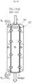
- FIG. 2is a schematic drawing of an example of a reformer device 20 .
- FIGS. 3 a -3 dare schematic drawings of exemplary reaction chambers of a reformer device according to the invention.
- FIG. 4is a graph depicting the reactor temperature within an embodiment of a reaction chamber of the invention as a function of the efficiency of a membrane in a reaction chamber of the invention.
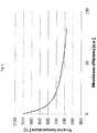
- FIG. 5is a graph depicting an increase in H 2 production as a function of the CO 2 permeance of the membrane in an embodiment of a reaction chamber of the invention.
- the orientation of the reformer device of the inventionis not limited to the orientation shown in the FIGS. 2 and 3 a - 3 d .
- the feedstock steamcould be input into the reformer device at the lower side thereof instead of at the upper side thereof, if appropriate.
- FIG. 1is a schematic drawing of a hydrogen plant 50 , comprising a feed purification unit 10 , a reformer 20 , a water gas shift unit 30 and a pressure swing adsorption unit 40 .
- Feedstock stream 1is input to the feed purification unit 10 .
- the feed purification unit 10is arranged to remove sulfur and/or chlorine compounds and/or to saturate olefins, including di-olefins in hydrocarbon feedstock streams.
- the feedstock streamis a hydrocarbon stream, such as for example natural gas/methane CH 4 .
- the reaction product 2is hydrogen (H 2 ).
- a prereforming unitmay be present (not shown in FIG. 1 ) for steam reforming of all higher hydrocarbons in the feedstock in order to provide more stable and mild operating conditions for the reformer device in carrying out the steam methane reforming.
- a prereformerWith a prereformer, the risk of carbon formation from higher hydrocarbons in the reaction chamber of the reformer device is reduced and the operating parameters, such as maximum average flux and temperature, can be optimized.
- heat integration and heat recoverycan be improved as the prereformed hydrocarbon/steam mixture can be preheated to a high temperature (typically 625-650° C.) without the risk of coking in the preheat coil.
- the reformer 20is a reformer device having one or more reaction chambers, e.g. reformer tubes, for carrying out a steam methane reforming reaction. Since the steam methane reforming reaction is endothermic, heat needs to be supplied, and therefore the one or more reaction chambers are placed within a heating reactor for heating the one or more reaction chambers. In order to provide the heat, fuel 4 is input into the heating reactor. An oxidant stream, such as oxygen or atmospheric air, may be input into the heating reactor together with the fuel 4 or via a separate input into the heating reactor.
- oxidant streamsuch as oxygen or atmospheric air
- the reformermay e.g. be a fired reformer, such as a top fired reformer or a bottom fired reformer, a radiant wall reformer, a convective reformer, a heat exchange reformer or a bayonet reformer.
- a fired reformersuch as a top fired reformer or a bottom fired reformer, a radiant wall reformer, a convective reformer, a heat exchange reformer or a bayonet reformer.
- An off-gas stream 3 from the PSA 40may also be input to the reformer 20 .
- the off-gas stream 3typically comprises CO 2 , H 2 and CH 4 , and is recycled to the heating reactor of the reformer 20 in order to use its fuel value.
- the streams 3 and 4are mixed into one stream 5 .
- the streams 3 and 4were input into separate inputs to the heating reactor.
- the catalyst material within the reformer deviceis arranged to carry out water gas shift in addition to steam methane reforming.
- a separate water gas shift unitmay be done without or at least reduced in size, if the water gas shift reaction carried out by the catalyst material within the reformer device is sufficient.
- a separate water gas shift unit 30may be present within the plant 50 .
- the water gas shift unit 30may be smaller than conventional water gas shift units if the catalyst within the reformer 20 is arranged to carry out water gas shift as well.
- the stream from the reformer 20comprises CO, CO 2 and H 2 .
- the stream output from the reformermainly comprises carbon dioxide CO 2 and hydrogen H 2
- the stream from the water gas shift unit 30(or the stream from the combined reformer and water gas shift unit 20 , in case of a hydrogen plant 50 without a separate water gas shift unit) mainly comprises carbon dioxide CO 2 and hydrogen H 2 .
- the stream from the water gas shift unit 30(or the stream from the combined reformer and water gas shift unit 20 , in case of a hydrogen plant 50 without a separate water gas shift unit) is input into a pressure swing adsorption (PSA) unit 40 arranged to separate carbon dioxide from hydrogen 2 .
- PSApressure swing adsorption
- the carbon dioxideis removed from the PSA unit 40 , and some of it is recycled as stream 3 to the heating reactor of the reformer 2 for temperature control.
- FIG. 1shows a hydrogen plant
- the inventionis not limited to hydrogen plants.
- the inventionis also advantageous in ammonia plants, since ammonia plants typically comprise expensive CO 2 removal units, which can be done without or at least reduced considerably in size in a plant with a reformer device of the invention.
- FIG. 2is a schematic drawing of an example of a reformer device 20 .
- the reformer device 20is a steam methane reformer and comprises a reaction chamber 22 and a surrounding heating reactor 24 .
- the reaction chamber 22comprises catalyst material 26 .
- the reaction chamber 22is shown as a single unit in FIG. 2 ; however, the reaction chamber 22 could be a plurality of reaction tubes instead of a single unit.
- a hydrocarbon stream 1 as a reactant gasis input into the reaction chamber 22 , and a hydrogen rich synthesis gas is output as a reaction product 7 .
- the hydrogen rich synthesis gas 7typically comprises H 2 and CO 2 .
- the hydrogen rich synthesis gas 7may also comprise carbon monoxide CO if only a partial or no water gas shift reaction takes place within the reaction chamber 22 .
- the hydrogen rich synthesis gasmay also comprise further constituents.
- the reaction chamber 22is surrounded by a heating reactor 24 , at least along majority of its length.
- the heating reactor 24 of FIG. 2 acomprises burners (not shown in FIG. 2 a ) for heating the reaction chamber, either directly or by heating the outer walls of the heating reactor 24 .
- the burnersuse fuel 5 (see FIG. 1 ) input into the reaction chamber, and effluent gas from the combustion is output as output stream 8 .
- a heating reactor 24may heat the reaction chamber 22 by convection or heat exchange with hot gas.
- the membrane within the reformer device 20is not shown in FIG. 2 ; the membrane is shown in FIGS. 3 a - 3 d.
- FIGS. 3 a -3 dare schematic drawings of exemplary reaction chambers of a reformer device according to the invention. It should be noted that the relative dimensions of the reaction chambers are not to scale in FIGS. 3 a -3 d . Instead the dimensions of FIGS. 3 a -3 d are changed in order to show the features thereof most clearly.
- FIG. 3 ais a schematic drawing of an exemplary reaction chamber 22 of a reformer device according 20 to the invention.
- the reaction chamber of the reformer device of the inventionmay be one out of a plurality of reaction chambers, e.g. one out of a plurality of steam reformer tubes.
- the embodiment shown in FIG. 3 ais an inner diffusion chamber with a co-current flow of sweep gas.
- the reaction chamber 22comprises a membrane 25 extending along all of a longitudinal axis (not shown in FIG. 3 a ) of the reaction chamber 22 .
- the membrane 25is placed as an inner tube within the reaction chamber so that during operation of the reformer device of the invention, CO 2 will diffuse from outside the inner tube into the inner tube as indicated by the horizontal arrows in FIG. 3 a .
- the membrane 25thus defines an inner diffusion chamber 28 .
- the reaction chamber 22 surrounding the inner diffusion chamber 28comprises catalyst material 26 arranged to catalyze both a steam methane reforming reaction and a water gas shift reaction.
- the catalyst material 26is thus confined to the space between the membrane 25 and the inner wall of the reaction 22 . In a cross-section perpendicular to the longitudinal axis of the reaction chamber 22 , this space is an annular space.
- the inner diffusion chamber 28has an inlet 1 ′ to admit a sweep gas arranged to sweep CO 2 diffused into the diffusion chamber through the diffusion chamber 28 and out through an outlet 7 ′ from the diffusion chamber 28 .
- the sweep gasmay be N 2 or H 2 O.
- the sweep gascould be any appropriate gas.
- the diameter of the inner tube formed by the membrane 25influences the production of hydrogen rich synthesis gas. Increasing the membrane diameter or the inner tube diameter will cause an increase in the production of hydrogen rich synthesis gas (syngas).
- the reaction chamber 22moreover comprises an inlet 1 for supply stream of hydrocarbon stream, e.g. natural gas CH 4 and H 2 O, and an outlet 7 for outletting hydrogen rich synthesis gas (syngas).
- FIG. 3 bis a schematic drawing of an exemplary reaction chamber 22 ′ of a reformer device 20 according to the invention.
- the reaction chamber 22 ′ of the reformer device of the inventionmay be one out of a plurality of reaction chambers, e.g. one out of a plurality of steam reformer tubes.
- the embodiment shown in FIG. 3 bis an outer diffusion chamber with a co-current flow of sweep gas.
- the reaction chamber 22 ′comprises a membrane 25 ′ extending along all of a longitudinal axis (not shown in FIG. 3 b ) of the reaction chamber 22 ′.
- the membrane 25 ′is placed as an inner tube within the reaction chamber.
- the inner tube of the reaction chamber 22 ′ as confined by the membrane 25 ′comprises catalyst material 26 ′ arranged to catalyze both a steam methane reforming reaction and a water gas shift reaction.
- the inner tube of the reaction chamber 22 ′ as confined by the membrane 25 ′is the reaction zone of the reaction chamber 22 ′, whilst the space as defined between the membrane 25 ′ and the inner wall of the reaction chamber 22 ′ along the longitudinal axis of the reaction chamber 22 ′ constitutes the diffusion chamber 28 ′.
- the inlet 1 for inletting a hydrocarbon streame.g. natural gas CH 4 and H 2 O
- a hydrocarbon streame.g. natural gas CH 4 and H 2 O
- an outlet 7 for outletting hydrogen rich synthesis gas (syngas)is also from the inner tube, since in the embodiment of FIG. 3 b CO 2 diffuses out from inside the inner tube, as indicated by the horizontal arrows in FIG. 3 b , into the diffusion chamber 28 ′ between the inner tube and the inside of the reaction chamber 22 ′.
- the membrane 25 ′defines a outer diffusion chamber 28 ′, the outer diffusion chamber 28 ′ having an inlet 1 ′ to admit a sweep gas arranged to sweep CO 2 diffused into the diffusion chamber out through the diffusion chamber 28 ′ and out through an outlet 7 ′ from the diffusion chamber 28 ′.
- the sweep gasmay be N 2 or H 2 O.
- the diameter of the inner tube formed by the membrane 25 ′influences the production of hydrogen rich synthesis gas. Increasing the membrane diameter or the inner tube diameter will cause an increase in the production of hydrogen rich synthesis gas (syngas).
- FIG. 3 cis a schematic drawing of an exemplary reaction chamber 22 ′′ of a reformer device according to the invention.
- the reaction chamber 22 ′′ of the reformer device 20 of the inventionmay be one out of a plurality of reaction chambers, e.g. one out of a plurality of steam reformer tubes.
- the reaction chamber 22 ′′comprises a membrane 25 ′′ extending along all of a longitudinal axis (not shown in FIG. 3 c ) of the reaction chamber 22 ′′.
- the embodiment shown in FIG. 3 cis an inner diffusion chamber with a counter-current flow of sweep gas.
- the membrane 25 ′′is placed as an inner tube within the reaction chamber so that during operation of the reformer device of the invention, CO 2 will diffuse from outside the inner tube into the inner tube as indicated with the horizontal arrows.
- the membrane 25 ′′thus defines an inner diffusion chamber 28 ′′.
- the reaction chamber 22 ′′ surrounding the inner diffusion chamber 28 ′′comprises catalyst material 26 ′′ arranged to catalyze both a steam methane reforming reaction and a water gas shift reaction.
- the catalyst material 26 ′′is thus confined to the space between the membrane 25 ′′ and the inner wall of the reaction 22 ′′. In a cross-section perpendicular to the longitudinal axis of the reaction chamber 22 ′′, this space with catalyst material 26 ′′ is an annular space.
- the inner diffusion chamber 28 ′′has an inlet 1 ′′ to admit a sweep gas arranged to sweep CO 2 diffused into the diffusion chamber out through an outlet 7 ′′ from the diffusion chamber 28 ′′.
- the sweep gasmay be N 2 or H 2 O.
- the reaction chamber 22 ′′moreover comprises an inlet 1 for supply stream of hydrocarbon stream, e.g. natural gas CH 4 and H 2 O, and an outlet 7 for outletting hydrogen rich synthesis gas (syngas).
- FIG. 3 dis a schematic drawing of an exemplary reaction chamber 22 ′′′ of a reformer device according to the invention.
- the reaction chamber 22 ′′′ of the reformer device 20 of the inventionmay be one out of a plurality of reaction chambers, e.g. one out of a plurality of steam reformer tubes.
- the reaction chamber 22 ′′′comprises a membrane 25 ′′′ extending along all of a longitudinal axis (not shown in FIG. 3 d ) of the reaction chamber 22 ′′′.
- the embodiment shown in FIG. 3 dis an outer diffusion chamber with a counter-current flow of sweep gas.
- the inner tube of the reaction chamber 22 ′′′ as confined by the membrane 25 ′′′comprises catalyst material 26 ′′′ arranged to catalyze both a steam methane reforming reaction and a water gas shift reaction.
- the inner tube of the reaction chamber 22 ′′′ as confined by the membrane 25 ′′′is the reaction zone of the reaction chamber 22 ′′′, whilst the space as defined between the membrane 25 ′′′ and the inner wall of the reaction chamber 22 ′′′ along the longitudinal axis of the reaction chamber 22 ′′′ constitutes the diffusion chamber 28 ′′′.
- the membrane 25 ′′′defines a outer diffusion chamber 28 ′′′, the outer diffusion chamber 28 ′′′ having an inlet 1 ′′′ to admit a sweep gas arranged to sweep CO 2 diffused into the diffusion chamber through the outer diffusion chamber 28 ′′′ and out through an outlet 7 ′′′ from the outer diffusion chamber 28 ′′′.
- the sweep gasmay be N 2 or H 2 O.
- the reaction chamber 22 ′′′moreover comprises an inlet 1 for supply stream of hydrocarbon stream, e.g. natural gas CH 4 and H 2 O, and an outlet 7 for outletting hydrogen rich synthesis gas (syngas).
- syngashydrogen rich synthesis gas
- CO 2diffuses out from inside the reaction zone or inner tube as defined by the membrane 25 ′′′, as indicated by the horizontal arrows in FIG. 3 d , into the outer diffusion chamber 28 ′′′ defined between the inner tube and the inside of the reaction chamber 22 ′′′.
- FIG. 4is a graph depicting the reactor temperature within a reaction chamber of the invention as a function of the efficiency of a membrane in the reaction chamber of the invention.
- the graph of FIG. 4shows the result of a simulation of how the exit temperature from the reaction chamber can be decreased from 950° C., which is a typical outlet temperature from a conventional reformer, to a temperature of below 700° C. in a reformer of the invention, operating with an efficient membrane which continuously removes CO 2 from the product gas and still produces the same amount of hydrogen.
- the membrane efficiencyis indicated in arbitrary units ([a.u.]).
- FIG. 5is a graph depicting an increase in H 2 production as a function of the CO 2 permeance of the membrane in a reaction chamber of the invention.
- FIG. 5shows that the hydrogen production yield can be increased in a reaction chamber of a reformer device, with a CO 2 membrane, compared to a reaction chamber operated at similar conditions, but without the membrane.
- FIG. 5also shows calculations of the increase in hydrogen production yield in a case, where the membrane is only provided in the most downstream one third of the reaction chamber. Simulations have revealed that intensive removal of CO 2 from the upstream part of the reaction chamber leads to decreasing production of hydrogen rich synthesis gas, especially in the case of a sweep gas in co-current with the reactant gas.
- FIG. 5show that a design where the membrane is provided in the most downstream one third of the reaction chamber has the same efficiency as a similar reaction chamber with a membrane throughout the whole length of the reaction chamber for permeance values above 7.5 kmol/m 2 /h/atm. This is noteworthy in relation to cost considerations in that expenses for a CO 2 membrane can be high.
Landscapes
- Chemical & Material Sciences (AREA)
- Chemical Kinetics & Catalysis (AREA)
- Organic Chemistry (AREA)
- Engineering & Computer Science (AREA)
- Combustion & Propulsion (AREA)
- Inorganic Chemistry (AREA)
- Health & Medical Sciences (AREA)
- General Health & Medical Sciences (AREA)
- Hydrogen, Water And Hydrids (AREA)
- Separation Using Semi-Permeable Membranes (AREA)
- Carbon And Carbon Compounds (AREA)
Abstract
Description
CH4+H2O=CO+3H2 (1)
CO+H2O=CO2+H2 (2)
CnHm+nH2O=nCO+(n+½m)H2 (3)
CH4+2H2O=CO2+4H2 (4)
- The heat to be provided by the heating reactor is decreased. In case the heating reactor is a fired reactor, the firing intensity is decreased.
- The size of a waste heat section for cooling down an effluent from the heating reactor is decreased due to the decreased requirements for heat provided by the heating reactor.
- The demands on the material of the reaction chamber are decreased, which allows for thinner walls of the reaction chamber and/or and less expensive types of material, compared to current reaction chambers.
Claims (12)
Applications Claiming Priority (4)
| Application Number | Priority Date | Filing Date | Title |
|---|---|---|---|
| DKPA201500214 | 2015-04-08 | ||
| DK201500214 | 2015-04-08 | ||
| DKPA201500214 | 2015-04-08 | ||
| PCT/EP2016/057092WO2016162263A1 (en) | 2015-04-08 | 2016-03-31 | Reformer device comprising a co2 membrane |
Publications (2)
| Publication Number | Publication Date |
|---|---|
| US20180079643A1 US20180079643A1 (en) | 2018-03-22 |
| US10647573B2true US10647573B2 (en) | 2020-05-12 |
Family
ID=55642493
Family Applications (1)
| Application Number | Title | Priority Date | Filing Date |
|---|---|---|---|
| US15/564,521Active2036-06-06US10647573B2 (en) | 2015-04-08 | 2016-03-31 | Reformer device comprising a CO2 membrane |
Country Status (8)
| Country | Link |
|---|---|
| US (1) | US10647573B2 (en) |
| EP (1) | EP3280679B1 (en) |
| JP (2) | JP2018512368A (en) |
| KR (1) | KR102341960B1 (en) |
| CN (1) | CN107428528B (en) |
| EA (1) | EA038495B1 (en) |
| SA (1) | SA517390108B1 (en) |
| WO (1) | WO2016162263A1 (en) |
Families Citing this family (17)
| Publication number | Priority date | Publication date | Assignee | Title |
|---|---|---|---|---|
| AT517934B1 (en)* | 2016-04-28 | 2017-06-15 | Mair Christian | Plant and process for the gas compression-free recovery and storage of carbon in energy storage systems |
| WO2019181687A1 (en)* | 2018-03-23 | 2019-09-26 | 住友精化株式会社 | Hydrogen production device and hydrogen production method |
| JP2021017380A (en)* | 2019-07-18 | 2021-02-15 | 株式会社デンソー | Fuel reforming system |
| MX2022010245A (en)* | 2020-02-28 | 2022-09-19 | Topsoe As | METHOD FOR THE PREPARATION OF SYNTHESIS GAS. |
| US11492255B2 (en) | 2020-04-03 | 2022-11-08 | Saudi Arabian Oil Company | Steam methane reforming with steam regeneration |
| US11322766B2 (en) | 2020-05-28 | 2022-05-03 | Saudi Arabian Oil Company | Direct hydrocarbon metal supported solid oxide fuel cell |
| US11639290B2 (en) | 2020-06-04 | 2023-05-02 | Saudi Arabian Oil Company | Dry reforming of methane with carbon dioxide at elevated pressure |
| US11492254B2 (en) | 2020-06-18 | 2022-11-08 | Saudi Arabian Oil Company | Hydrogen production with membrane reformer |
| US11583824B2 (en) | 2020-06-18 | 2023-02-21 | Saudi Arabian Oil Company | Hydrogen production with membrane reformer |
| US11999619B2 (en) | 2020-06-18 | 2024-06-04 | Saudi Arabian Oil Company | Hydrogen production with membrane reactor |
| US12220666B2 (en) | 2021-01-12 | 2025-02-11 | Saudi Arabian Oil Company | Ultrathin membrane fabrication |
| US11787759B2 (en) | 2021-08-12 | 2023-10-17 | Saudi Arabian Oil Company | Dimethyl ether production via dry reforming and dimethyl ether synthesis in a vessel |
| US12258272B2 (en) | 2021-08-12 | 2025-03-25 | Saudi Arabian Oil Company | Dry reforming of methane using a nickel-based bi-metallic catalyst |
| US11718575B2 (en) | 2021-08-12 | 2023-08-08 | Saudi Arabian Oil Company | Methanol production via dry reforming and methanol synthesis in a vessel |
| US11578016B1 (en) | 2021-08-12 | 2023-02-14 | Saudi Arabian Oil Company | Olefin production via dry reforming and olefin synthesis in a vessel |
| US11617981B1 (en) | 2022-01-03 | 2023-04-04 | Saudi Arabian Oil Company | Method for capturing CO2 with assisted vapor compression |
| KR20250032129A (en)* | 2023-08-30 | 2025-03-07 | (주)부흥산업사 | A method for reforming any reducing gas for production of syngas and its reforming process system |
Citations (29)
| Publication number | Priority date | Publication date | Assignee | Title |
|---|---|---|---|---|
| WO1999006138A1 (en) | 1997-08-01 | 1999-02-11 | Exxon Research And Engineering Company | Co2-selective membrane process and system for reforming a fuel to hydrogen for a fuel cell |
| US6090312A (en) | 1996-01-31 | 2000-07-18 | Ziaka; Zoe D. | Reactor-membrane permeator process for hydrocarbon reforming and water gas-shift reactions |
| US20030066239A1 (en)* | 2001-10-05 | 2003-04-10 | Iraj Parchamazad | Portable cogeneration fuel-cell power generator with high-yield, low pressure reformer for recreational vehicles |
| WO2003072493A1 (en) | 2002-02-27 | 2003-09-04 | Volvo Technology Corporation | System for generating hydrogen fuel to a fuel cell |
| WO2004069739A1 (en) | 2003-02-05 | 2004-08-19 | Siemens Aktiengesellschaft | Method and device for separating co2 contained in an h2-based gaseous mixture |
| JP2004244275A (en) | 2003-02-14 | 2004-09-02 | Corona Corp | Method and apparatus for producing high-purity hydrogen from hydrocarbon fuel |
| US20070024057A1 (en) | 2005-07-28 | 2007-02-01 | Jaswinder Sehmbi | Conduit assembly and method of making same |
| WO2007142518A1 (en) | 2006-05-04 | 2007-12-13 | Stichting Energieonderzoek Centrum Nederland | A reactor device, and a method for carrying out a reaction with hydrogen as reaction product |
| US20090101008A1 (en) | 2007-10-18 | 2009-04-23 | Lackner Klaus S | Carbon dioxide permeable membrane |
| US20100129284A1 (en)* | 2007-03-29 | 2010-05-27 | Nippon Oil Corporation | Method and apparatus for producing hydrogen and recovering carbon dioxide |
| US20100152900A1 (en)* | 2008-10-10 | 2010-06-17 | Exxonmobil Research And Engineering Company | Optimizing refinery hydrogen gas supply, distribution and consumption in real time |
| US20100260657A1 (en)* | 2007-07-27 | 2010-10-14 | Nippon Oil Corporation | Method and apparatus for hydrogen production and carbon dioxide recovery |
| US7938893B2 (en) | 2006-04-18 | 2011-05-10 | Gas Technology Institute | Membrane reactor for H2S, CO2 and H2 separation |
| US20110168572A1 (en) | 2010-01-12 | 2011-07-14 | University Of South Carolina | Composite Mixed Carbonate Ion and Electron Conducting Membranes and Reactant Gas Assisted Chemical Reactors for CO2 Separation and Capture |
| US20120014852A1 (en) | 2010-07-13 | 2012-01-19 | Kevin Huang | Membranes and Reactors for CO2 Separation |
| US20120039794A1 (en) | 2009-01-30 | 2012-02-16 | Johnson Matthey Plc | Hydrogen process |
| US20120121497A1 (en)* | 2010-11-11 | 2012-05-17 | Air Liquide Large Industries U.S. Lp | Process For Recovering Hydrogen And Carbon Dioxide |
| US20120118011A1 (en)* | 2010-11-11 | 2012-05-17 | Air Liquide Large Industries U.S. Lp | Process For The Production Of Hydrogen And Carbon Dioxide |
| WO2012086836A1 (en) | 2010-12-24 | 2012-06-28 | 株式会社ルネッサンス・エナジー・リサーチ | Gas separation device, membrane reactor, and hydrogen production device |
| US20120291483A1 (en)* | 2011-05-18 | 2012-11-22 | Air Liquide Large Industries U.S. Lp | Process For Recovering Hydrogen And Carbon Dioxide |
| US20120292574A1 (en)* | 2011-05-18 | 2012-11-22 | Air Liquide Large Industries U.S. Lp | Process For The Production Of Hydrogen And Carbon Dioxide |
| US20130072583A1 (en)* | 2010-05-10 | 2013-03-21 | Neste Oil Oyi | Method of producing a hydrocarbon composition |
| US8430938B1 (en)* | 2006-07-13 | 2013-04-30 | The United States Of America As Represented By The Secretary Of The Navy | Control algorithm for autothermal reformer |
| US20140170061A1 (en)* | 2012-12-18 | 2014-06-19 | L'Air Liquide Societe Anonyme Pour l'Etude et l'Exploitation des Precedes Georges Claude | Staged membrane process for high pressure hydrogen production |
| US20140264176A1 (en) | 2013-03-14 | 2014-09-18 | Membrane Technology And Research, Inc. | Membrane-Based Gas Separation Processes to Produce Synthesis Gas With a High CO Content |
| US20140357737A1 (en)* | 2011-09-15 | 2014-12-04 | Peter Edward James Abbott | Synthesis gas and fischer tropsch integrated process |
| US20150047989A1 (en) | 2013-08-16 | 2015-02-19 | University Of South Carolina | Combined co2 capture and conversion method and system |
| US20150090125A1 (en) | 2013-09-05 | 2015-04-02 | The Arizona Board Of Regents For And On Behalf Of Arizona State University | Tubular ceramic-carbonate dual-phase membranes and methods of manufacture thereof |
| US20150323248A1 (en)* | 2012-04-07 | 2015-11-12 | L'air Liquide, Societe Anonyme Pour I'etude Et I'exploitation Des Procedes Georges Claude | Process for recovering hydrogen and capturing carbon dioxide |
Family Cites Families (6)
| Publication number | Priority date | Publication date | Assignee | Title |
|---|---|---|---|---|
| US7572318B2 (en)* | 2006-04-18 | 2009-08-11 | Gas Technology Institute | High-temperature membrane for CO2 and/or H2S separation |
| WO2009042244A1 (en)* | 2007-09-28 | 2009-04-02 | The Trustees Of Columbia University In The City Of New York | Methods and systems for generating hydgrogen and separating carbon dioxide |
| EP2199254A1 (en)* | 2008-12-11 | 2010-06-23 | BP p.l.c. | Integrated gas refinery |
| JP2010189217A (en)* | 2009-02-17 | 2010-09-02 | Keio Gijuku | Reformer and reforming method |
| JP2010235736A (en)* | 2009-03-31 | 2010-10-21 | Toyota Motor Corp | Synthetic fuel production system |
| JP2012066961A (en)* | 2010-09-22 | 2012-04-05 | Idemitsu Kosan Co Ltd | Method of generating hydrogen from hydrocarbon compound |
- 2016
- 2016-03-31USUS15/564,521patent/US10647573B2/enactiveActive
- 2016-03-31EAEA201792192Apatent/EA038495B1/enunknown
- 2016-03-31CNCN201680020638.9Apatent/CN107428528B/enactiveActive
- 2016-03-31JPJP2017552985Apatent/JP2018512368A/enactivePending
- 2016-03-31EPEP16712912.1Apatent/EP3280679B1/enactiveActive
- 2016-03-31KRKR1020177029211Apatent/KR102341960B1/enactiveActive
- 2016-03-31WOPCT/EP2016/057092patent/WO2016162263A1/ennot_activeCeased
- 2017
- 2017-10-05SASA517390108Apatent/SA517390108B1/enunknown
- 2020
- 2020-12-01JPJP2020199490Apatent/JP7096317B2/enactiveActive
Patent Citations (38)
| Publication number | Priority date | Publication date | Assignee | Title |
|---|---|---|---|---|
| US6090312A (en) | 1996-01-31 | 2000-07-18 | Ziaka; Zoe D. | Reactor-membrane permeator process for hydrocarbon reforming and water gas-shift reactions |
| WO1999006138A1 (en) | 1997-08-01 | 1999-02-11 | Exxon Research And Engineering Company | Co2-selective membrane process and system for reforming a fuel to hydrogen for a fuel cell |
| JP2001511430A (en) | 1997-08-01 | 2001-08-14 | エクソンモービル リサーチ アンド エンジニアリング カンパニー | CO2 selective membrane process and system for reforming fuel to hydrogen for fuel cells |
| US6579331B1 (en) | 1997-08-01 | 2003-06-17 | Exxonmobil Research And Engineering Company | CO2-Selective membrane process and system for reforming a fuel to hydrogen for a fuel cell |
| US20030066239A1 (en)* | 2001-10-05 | 2003-04-10 | Iraj Parchamazad | Portable cogeneration fuel-cell power generator with high-yield, low pressure reformer for recreational vehicles |
| US20050000161A1 (en) | 2002-02-27 | 2005-01-06 | Volvo Technology Corporation | System for generating hydrogen fuel for a fuel cell |
| JP2005519012A (en) | 2002-02-27 | 2005-06-30 | ボルボ テクノロジー コーポレイション | Hydrogen fuel generation system for fuel cells |
| CN1639057A (en) | 2002-02-27 | 2005-07-13 | 沃尔沃技术公司 | System for generating hydrogen fuel to a fuel cell |
| WO2003072493A1 (en) | 2002-02-27 | 2003-09-04 | Volvo Technology Corporation | System for generating hydrogen fuel to a fuel cell |
| JP2009179555A (en) | 2002-02-27 | 2009-08-13 | Volvo Technology Corp | System for generating hydrogen fuel for fuel cell |
| WO2004069739A1 (en) | 2003-02-05 | 2004-08-19 | Siemens Aktiengesellschaft | Method and device for separating co2 contained in an h2-based gaseous mixture |
| JP2004244275A (en) | 2003-02-14 | 2004-09-02 | Corona Corp | Method and apparatus for producing high-purity hydrogen from hydrocarbon fuel |
| US8163065B2 (en) | 2005-04-18 | 2012-04-24 | The Trustees Of Columbia University In The City Of New York | Carbon dioxide permeable membrane |
| US20070024057A1 (en) | 2005-07-28 | 2007-02-01 | Jaswinder Sehmbi | Conduit assembly and method of making same |
| US7938893B2 (en) | 2006-04-18 | 2011-05-10 | Gas Technology Institute | Membrane reactor for H2S, CO2 and H2 separation |
| WO2007142518A1 (en) | 2006-05-04 | 2007-12-13 | Stichting Energieonderzoek Centrum Nederland | A reactor device, and a method for carrying out a reaction with hydrogen as reaction product |
| US20100044642A1 (en) | 2006-05-04 | 2010-02-25 | Stichting Energieonderzoek Centrum Nederland | Reactor device, and a method for carrying out a reaction with hydrogen as reaction product |
| US8430938B1 (en)* | 2006-07-13 | 2013-04-30 | The United States Of America As Represented By The Secretary Of The Navy | Control algorithm for autothermal reformer |
| US20100129284A1 (en)* | 2007-03-29 | 2010-05-27 | Nippon Oil Corporation | Method and apparatus for producing hydrogen and recovering carbon dioxide |
| US20100260657A1 (en)* | 2007-07-27 | 2010-10-14 | Nippon Oil Corporation | Method and apparatus for hydrogen production and carbon dioxide recovery |
| US20090101008A1 (en) | 2007-10-18 | 2009-04-23 | Lackner Klaus S | Carbon dioxide permeable membrane |
| US20100152900A1 (en)* | 2008-10-10 | 2010-06-17 | Exxonmobil Research And Engineering Company | Optimizing refinery hydrogen gas supply, distribution and consumption in real time |
| US20120039794A1 (en) | 2009-01-30 | 2012-02-16 | Johnson Matthey Plc | Hydrogen process |
| US20110168572A1 (en) | 2010-01-12 | 2011-07-14 | University Of South Carolina | Composite Mixed Carbonate Ion and Electron Conducting Membranes and Reactant Gas Assisted Chemical Reactors for CO2 Separation and Capture |
| US20130072583A1 (en)* | 2010-05-10 | 2013-03-21 | Neste Oil Oyi | Method of producing a hydrocarbon composition |
| US20120014852A1 (en) | 2010-07-13 | 2012-01-19 | Kevin Huang | Membranes and Reactors for CO2 Separation |
| US20120121497A1 (en)* | 2010-11-11 | 2012-05-17 | Air Liquide Large Industries U.S. Lp | Process For Recovering Hydrogen And Carbon Dioxide |
| US20120118011A1 (en)* | 2010-11-11 | 2012-05-17 | Air Liquide Large Industries U.S. Lp | Process For The Production Of Hydrogen And Carbon Dioxide |
| WO2012086836A1 (en) | 2010-12-24 | 2012-06-28 | 株式会社ルネッサンス・エナジー・リサーチ | Gas separation device, membrane reactor, and hydrogen production device |
| US20130287678A1 (en) | 2010-12-24 | 2013-10-31 | Renaissance Energy Corporation | Gas separation apparatus, membrane reactor, and hydrogen production apparatus |
| US20120292574A1 (en)* | 2011-05-18 | 2012-11-22 | Air Liquide Large Industries U.S. Lp | Process For The Production Of Hydrogen And Carbon Dioxide |
| US20120291483A1 (en)* | 2011-05-18 | 2012-11-22 | Air Liquide Large Industries U.S. Lp | Process For Recovering Hydrogen And Carbon Dioxide |
| US20140357737A1 (en)* | 2011-09-15 | 2014-12-04 | Peter Edward James Abbott | Synthesis gas and fischer tropsch integrated process |
| US20150323248A1 (en)* | 2012-04-07 | 2015-11-12 | L'air Liquide, Societe Anonyme Pour I'etude Et I'exploitation Des Procedes Georges Claude | Process for recovering hydrogen and capturing carbon dioxide |
| US20140170061A1 (en)* | 2012-12-18 | 2014-06-19 | L'Air Liquide Societe Anonyme Pour l'Etude et l'Exploitation des Precedes Georges Claude | Staged membrane process for high pressure hydrogen production |
| US20140264176A1 (en) | 2013-03-14 | 2014-09-18 | Membrane Technology And Research, Inc. | Membrane-Based Gas Separation Processes to Produce Synthesis Gas With a High CO Content |
| US20150047989A1 (en) | 2013-08-16 | 2015-02-19 | University Of South Carolina | Combined co2 capture and conversion method and system |
| US20150090125A1 (en) | 2013-09-05 | 2015-04-02 | The Arizona Board Of Regents For And On Behalf Of Arizona State University | Tubular ceramic-carbonate dual-phase membranes and methods of manufacture thereof |
Non-Patent Citations (10)
| Title |
|---|
| Danish Search Report dated Oct. 21, 2015, issued by the Danish Patent Office in the corresponding Danish Patent Application No. PA 2015 00214. (7 pages). |
| International Search Report (PCT/ISA/210) dated Jul. 8, 2016, by the European Patent Office as the International Searching Authority for International Application No. PCT/EP2016/057092. |
| Lima, A.A.G. et al., "Composition effects on the activity of Cu-Zn0-Al203 based catalysts for the water gas shift reaction: A statistical approach", Applied Catalysis A: General, vol. 171, No. 1, pp. 31-43, Jun. 29, 1998, XP004271466. |
| LIMA, A.A.G. NELE, M. MORENO, E.L. ANDRADE, H.M.C.: "Composition effects on the activity of Cu-ZnO-Al"2O"3 based catalysts for the water gas shift reaction: A statistical approach", APPLIED CATALYSIS A: GENERAL, ELSEVIER, AMSTERDAM, NL, vol. 171, no. 1, 29 June 1998 (1998-06-29), AMSTERDAM, NL, pages 31 - 43, XP004271466, ISSN: 0926-860X, DOI: 10.1016/S0926-860X(98)00072-6 |
| Office Action (First Office Action) dated Jun. 26, 2019, by the China National Intellectual Property Administration (CNIPA) in corresponding Chinese Patent Application No. 201680020638.9 and an English Translation of the Office Action. (18 pages). |
| Office Action (Notice of Reasons for Refusal) dated Oct. 23, 2019, by the Japanese Patent Office in corresponding Japanese Patent Application No. 2017-552985, and an English Translation of the Office Action. (10 pages). |
| Written Opinion (PCT/ISA/237) dated Jul. 8, 2016, by the European Patent Office as the International Searching Authority for International Application No. PCT/EP2016/057092. |
| Wu, Exhibition 1: Flow chart for hydrogen production by methane steam reforming, in Hydrogen Energy and Hydrogen Producing Technologies, Zhejiang University Press, Sep. 30, 2014, pp. 65-66, (7 pages). |
| ZOU J, HUANG J, WINSTON W S: "CO2-Selective Water Gas Shift Membrane Reactor for Fuel Cell Hydrogen Processing", INDUSTRIAL & ENGINEERING CHEMISTRY RESEARCH, vol. 46, no. 8, 11 April 2007 (2007-04-11), pages 2272 - 2279, XP002571135, ISSN: 0888-5885, DOI: 10.1021/ie0611453 |
| Zou, J. et al., "C02-Selective Water Gas Shift Membrane Reactor for Fuel Cell Hydrogen Processing", Industrial & Engineering Chemistry Research, American Chemical Society, vol. 46, No. 8, pp. 2272-2279, Apr. 11, 2007, XP-002571135. |
Also Published As
| Publication number | Publication date |
|---|---|
| JP2021054714A (en) | 2021-04-08 |
| EA201792192A1 (en) | 2018-05-31 |
| KR102341960B1 (en) | 2021-12-23 |
| KR20170134484A (en) | 2017-12-06 |
| JP7096317B2 (en) | 2022-07-05 |
| CN107428528A (en) | 2017-12-01 |
| US20180079643A1 (en) | 2018-03-22 |
| EP3280679B1 (en) | 2021-01-13 |
| SA517390108B1 (en) | 2022-02-16 |
| JP2018512368A (en) | 2018-05-17 |
| WO2016162263A1 (en) | 2016-10-13 |
| EA038495B1 (en) | 2021-09-07 |
| EP3280679A1 (en) | 2018-02-14 |
| CN107428528B (en) | 2021-09-10 |
Similar Documents
| Publication | Publication Date | Title |
|---|---|---|
| US10647573B2 (en) | Reformer device comprising a CO2 membrane | |
| US11591214B2 (en) | Process and system for producing synthesis gas | |
| US12172896B2 (en) | ATR-based hydrogen process and plant | |
| US8580153B2 (en) | Hydrogen production with reduced carbon dioxide generation and complete capture | |
| IL271938B2 (en) | A method for making synthesis gas | |
| US9114352B2 (en) | Staged membrane process for high pressure hydrogen production | |
| AU2018308586A1 (en) | Method for the preparation of ammonia synthesis gas | |
| US9458013B1 (en) | Process for the production of hydrogen | |
| US20240101417A1 (en) | Method for preparing a synthesis gas | |
| KR102674399B1 (en) | Systems and methods for producing synthesis gas | |
| KR102517055B1 (en) | Systems and methods for producing syngas | |
| CN119894815A (en) | ATR reforming | |
| US10093541B2 (en) | Process for producing synthesis gas | |
| RU2664516C2 (en) | Method and system for producing methanol using integrated oxygen transport membrane based reforming system | |
| EP1441981B1 (en) | Reactor for reformation of natural gas and simultaneous production of hydrogen | |
| TW202502646A (en) | Plant and process for producing hydrogen from hydrocarbons with reduced co emissions | |
| EA040289B1 (en) | SYSTEM AND METHOD FOR PRODUCING SYNTHESIS GAS | |
| EP3098197B1 (en) | Process for the production of hydrogen | |
| WO2025012699A1 (en) | Plant and process for producing hydrogen from hydrocarbons with reduced co2 emissions | |
| EA044781B1 (en) | METHOD AND SYSTEM FOR PRODUCING SYNTHESIS GAS |
Legal Events
| Date | Code | Title | Description |
|---|---|---|---|
| FEPP | Fee payment procedure | Free format text:ENTITY STATUS SET TO UNDISCOUNTED (ORIGINAL EVENT CODE: BIG.); ENTITY STATUS OF PATENT OWNER: LARGE ENTITY | |
| AS | Assignment | Owner name:HALDOR TOPSOEE A/S, DENMARK Free format text:ASSIGNMENT OF ASSIGNORS INTEREST;ASSIGNORS:OESTBERG, MARTIN;MORTENSEN, PETER MOELGAARD;SIGNING DATES FROM 20150428 TO 20150430;REEL/FRAME:043805/0117 | |
| AS | Assignment | Owner name:HALDOR TOPSOEE A/S, DENMARK Free format text:CHANGE OF ADDRESS OF ASSIGNEE;ASSIGNOR:HALDOR TOPSOEE A/S;REEL/FRAME:044169/0097 Effective date:20171010 | |
| STPP | Information on status: patent application and granting procedure in general | Free format text:DOCKETED NEW CASE - READY FOR EXAMINATION | |
| STPP | Information on status: patent application and granting procedure in general | Free format text:NON FINAL ACTION MAILED | |
| STPP | Information on status: patent application and granting procedure in general | Free format text:RESPONSE TO NON-FINAL OFFICE ACTION ENTERED AND FORWARDED TO EXAMINER | |
| STPP | Information on status: patent application and granting procedure in general | Free format text:NON FINAL ACTION MAILED | |
| STPP | Information on status: patent application and granting procedure in general | Free format text:NOTICE OF ALLOWANCE MAILED -- APPLICATION RECEIVED IN OFFICE OF PUBLICATIONS | |
| STCF | Information on status: patent grant | Free format text:PATENTED CASE | |
| AS | Assignment | Owner name:TOPSOE A/S, DENMARK Free format text:CHANGE OF NAME;ASSIGNOR:HALDOR TOPSOEE A/S;REEL/FRAME:065385/0395 Effective date:20220412 | |
| MAFP | Maintenance fee payment | Free format text:PAYMENT OF MAINTENANCE FEE, 4TH YEAR, LARGE ENTITY (ORIGINAL EVENT CODE: M1551); ENTITY STATUS OF PATENT OWNER: LARGE ENTITY Year of fee payment:4 |