US10647569B2 - Methods of manufacture for MEMS switches with reduced switching voltage - Google Patents
Methods of manufacture for MEMS switches with reduced switching voltageDownload PDFInfo
- Publication number
- US10647569B2 US10647569B2US15/717,187US201715717187AUS10647569B2US 10647569 B2US10647569 B2US 10647569B2US 201715717187 AUS201715717187 AUS 201715717187AUS 10647569 B2US10647569 B2US 10647569B2
- Authority
- US
- United States
- Prior art keywords
- electrode
- voltage
- cantilevered
- cantilever
- forming
- Prior art date
- Legal status (The legal status is an assumption and is not a legal conclusion. Google has not performed a legal analysis and makes no representation as to the accuracy of the status listed.)
- Expired - Fee Related, expires
Links
- 238000004519manufacturing processMethods0.000titleclaimsabstractdescription15
- 238000000034methodMethods0.000titleclaimsdescription47
- 150000004767nitridesChemical class0.000claimsdescription18
- 230000008021depositionEffects0.000claimsdescription11
- 239000000463materialSubstances0.000claimsdescription7
- 238000000151depositionMethods0.000description15
- 238000000059patterningMethods0.000description8
- 239000012212insulatorSubstances0.000description6
- 229910052751metalInorganic materials0.000description6
- 239000002184metalSubstances0.000description6
- 235000012431wafersNutrition0.000description6
- 230000015556catabolic processEffects0.000description5
- 239000003989dielectric materialSubstances0.000description5
- 239000011800void materialSubstances0.000description4
- IAZDPXIOMUYVGZ-UHFFFAOYSA-NDimethylsulphoxideChemical compoundCS(C)=OIAZDPXIOMUYVGZ-UHFFFAOYSA-N0.000description3
- SECXISVLQFMRJM-UHFFFAOYSA-NN-MethylpyrrolidoneChemical compoundCN1CCCC1=OSECXISVLQFMRJM-UHFFFAOYSA-N0.000description3
- 238000005452bendingMethods0.000description3
- 238000005229chemical vapour depositionMethods0.000description3
- 239000010949copperSubstances0.000description3
- 238000005530etchingMethods0.000description3
- 229910001092metal group alloyInorganic materials0.000description3
- 238000012986modificationMethods0.000description3
- 230000004048modificationEffects0.000description3
- JBRZTFJDHDCESZ-UHFFFAOYSA-NAsGaChemical compound[As]#[Ga]JBRZTFJDHDCESZ-UHFFFAOYSA-N0.000description2
- 229910001218Gallium arsenideInorganic materials0.000description2
- ATJFFYVFTNAWJD-UHFFFAOYSA-NTinChemical compound[Sn]ATJFFYVFTNAWJD-UHFFFAOYSA-N0.000description2
- 238000007792additionMethods0.000description2
- 239000007795chemical reaction productSubstances0.000description2
- 239000004020conductorSubstances0.000description2
- 229910052802copperInorganic materials0.000description2
- 238000005516engineering processMethods0.000description2
- 239000010408filmSubstances0.000description2
- 229910052737goldInorganic materials0.000description2
- 239000010931goldSubstances0.000description2
- 150000002739metalsChemical class0.000description2
- 229920002120photoresistant polymerPolymers0.000description2
- 238000005240physical vapour depositionMethods0.000description2
- 238000001020plasma etchingMethods0.000description2
- 239000000047productSubstances0.000description2
- 229910052710siliconInorganic materials0.000description2
- 239000010703siliconSubstances0.000description2
- 239000010409thin filmSubstances0.000description2
- 229910052721tungstenInorganic materials0.000description2
- 229910016570AlCuInorganic materials0.000description1
- RYGMFSIKBFXOCR-UHFFFAOYSA-NCopperChemical compound[Cu]RYGMFSIKBFXOCR-UHFFFAOYSA-N0.000description1
- 229910001030Iron–nickel alloyInorganic materials0.000description1
- 229910052581Si3N4Inorganic materials0.000description1
- 229910004541SiNInorganic materials0.000description1
- 229910000577Silicon-germaniumInorganic materials0.000description1
- QVGXLLKOCUKJST-UHFFFAOYSA-Natomic oxygenChemical compound[O]QVGXLLKOCUKJST-UHFFFAOYSA-N0.000description1
- 230000015572biosynthetic processEffects0.000description1
- 239000000919ceramicSubstances0.000description1
- 230000003247decreasing effectEffects0.000description1
- 230000007812deficiencyEffects0.000description1
- 230000001419dependent effectEffects0.000description1
- 238000005137deposition processMethods0.000description1
- 238000007667floatingMethods0.000description1
- 239000011521glassSubstances0.000description1
- PCHJSUWPFVWCPO-UHFFFAOYSA-NgoldChemical compound[Au]PCHJSUWPFVWCPO-UHFFFAOYSA-N0.000description1
- 238000003384imaging methodMethods0.000description1
- 239000013067intermediate productSubstances0.000description1
- 238000002955isolationMethods0.000description1
- 238000001459lithographyMethods0.000description1
- 239000012528membraneSubstances0.000description1
- 238000001465metallisationMethods0.000description1
- 229910052760oxygenInorganic materials0.000description1
- 239000001301oxygenSubstances0.000description1
- 230000002035prolonged effectEffects0.000description1
- 239000010453quartzSubstances0.000description1
- 239000003870refractory metalSubstances0.000description1
- 238000007789sealingMethods0.000description1
- 230000035945sensitivityEffects0.000description1
- VYPSYNLAJGMNEJ-UHFFFAOYSA-Nsilicon dioxideInorganic materialsO=[Si]=OVYPSYNLAJGMNEJ-UHFFFAOYSA-N0.000description1
- 239000007787solidSubstances0.000description1
- 238000004528spin coatingMethods0.000description1
- 239000000758substrateSubstances0.000description1
- WFKWXMTUELFFGS-UHFFFAOYSA-NtungstenChemical compound[W]WFKWXMTUELFFGS-UHFFFAOYSA-N0.000description1
- 239000010937tungstenSubstances0.000description1
- 238000001039wet etchingMethods0.000description1
Images


Classifications
- B—PERFORMING OPERATIONS; TRANSPORTING
- B81—MICROSTRUCTURAL TECHNOLOGY
- B81C—PROCESSES OR APPARATUS SPECIALLY ADAPTED FOR THE MANUFACTURE OR TREATMENT OF MICROSTRUCTURAL DEVICES OR SYSTEMS
- B81C1/00—Manufacture or treatment of devices or systems in or on a substrate
- B81C1/00642—Manufacture or treatment of devices or systems in or on a substrate for improving the physical properties of a device
- B81C1/00698—Electrical characteristics, e.g. by doping materials
- B—PERFORMING OPERATIONS; TRANSPORTING
- B81—MICROSTRUCTURAL TECHNOLOGY
- B81C—PROCESSES OR APPARATUS SPECIALLY ADAPTED FOR THE MANUFACTURE OR TREATMENT OF MICROSTRUCTURAL DEVICES OR SYSTEMS
- B81C1/00—Manufacture or treatment of devices or systems in or on a substrate
- B81C1/00015—Manufacture or treatment of devices or systems in or on a substrate for manufacturing microsystems
- B81C1/00134—Manufacture or treatment of devices or systems in or on a substrate for manufacturing microsystems comprising flexible or deformable structures
- B81C1/0015—Cantilevers
- B—PERFORMING OPERATIONS; TRANSPORTING
- B81—MICROSTRUCTURAL TECHNOLOGY
- B81C—PROCESSES OR APPARATUS SPECIALLY ADAPTED FOR THE MANUFACTURE OR TREATMENT OF MICROSTRUCTURAL DEVICES OR SYSTEMS
- B81C1/00—Manufacture or treatment of devices or systems in or on a substrate
- B81C1/00015—Manufacture or treatment of devices or systems in or on a substrate for manufacturing microsystems
- B81C1/00134—Manufacture or treatment of devices or systems in or on a substrate for manufacturing microsystems comprising flexible or deformable structures
- B81C1/00166—Electrodes
- B—PERFORMING OPERATIONS; TRANSPORTING
- B81—MICROSTRUCTURAL TECHNOLOGY
- B81C—PROCESSES OR APPARATUS SPECIALLY ADAPTED FOR THE MANUFACTURE OR TREATMENT OF MICROSTRUCTURAL DEVICES OR SYSTEMS
- B81C1/00—Manufacture or treatment of devices or systems in or on a substrate
- B81C1/00436—Shaping materials, i.e. techniques for structuring the substrate or the layers on the substrate
- B81C1/00523—Etching material
- H—ELECTRICITY
- H01—ELECTRIC ELEMENTS
- H01H—ELECTRIC SWITCHES; RELAYS; SELECTORS; EMERGENCY PROTECTIVE DEVICES
- H01H1/00—Contacts
- H01H1/0036—Switches making use of microelectromechanical systems [MEMS]
- H—ELECTRICITY
- H01—ELECTRIC ELEMENTS
- H01H—ELECTRIC SWITCHES; RELAYS; SELECTORS; EMERGENCY PROTECTIVE DEVICES
- H01H11/00—Apparatus or processes specially adapted for the manufacture of electric switches
- H—ELECTRICITY
- H01—ELECTRIC ELEMENTS
- H01H—ELECTRIC SWITCHES; RELAYS; SELECTORS; EMERGENCY PROTECTIVE DEVICES
- H01H49/00—Apparatus or processes specially adapted to the manufacture of relays or parts thereof
- H—ELECTRICITY
- H01—ELECTRIC ELEMENTS
- H01H—ELECTRIC SWITCHES; RELAYS; SELECTORS; EMERGENCY PROTECTIVE DEVICES
- H01H59/00—Electrostatic relays; Electro-adhesion relays
- H—ELECTRICITY
- H01—ELECTRIC ELEMENTS
- H01H—ELECTRIC SWITCHES; RELAYS; SELECTORS; EMERGENCY PROTECTIVE DEVICES
- H01H59/00—Electrostatic relays; Electro-adhesion relays
- H01H59/0009—Electrostatic relays; Electro-adhesion relays making use of micromechanics
- B—PERFORMING OPERATIONS; TRANSPORTING
- B81—MICROSTRUCTURAL TECHNOLOGY
- B81C—PROCESSES OR APPARATUS SPECIALLY ADAPTED FOR THE MANUFACTURE OR TREATMENT OF MICROSTRUCTURAL DEVICES OR SYSTEMS
- B81C2201/00—Manufacture or treatment of microstructural devices or systems
- B81C2201/01—Manufacture or treatment of microstructural devices or systems in or on a substrate
- B81C2201/0101—Shaping material; Structuring the bulk substrate or layers on the substrate; Film patterning
- B81C2201/0128—Processes for removing material
- B81C2201/013—Etching
- B81C2201/0132—Dry etching, i.e. plasma etching, barrel etching, reactive ion etching [RIE], sputter etching or ion milling
- B—PERFORMING OPERATIONS; TRANSPORTING
- B81—MICROSTRUCTURAL TECHNOLOGY
- B81C—PROCESSES OR APPARATUS SPECIALLY ADAPTED FOR THE MANUFACTURE OR TREATMENT OF MICROSTRUCTURAL DEVICES OR SYSTEMS
- B81C2201/00—Manufacture or treatment of microstructural devices or systems
- B81C2201/01—Manufacture or treatment of microstructural devices or systems in or on a substrate
- B81C2201/0101—Shaping material; Structuring the bulk substrate or layers on the substrate; Film patterning
- B81C2201/0128—Processes for removing material
- B81C2201/013—Etching
- B81C2201/0133—Wet etching
- B—PERFORMING OPERATIONS; TRANSPORTING
- B81—MICROSTRUCTURAL TECHNOLOGY
- B81C—PROCESSES OR APPARATUS SPECIALLY ADAPTED FOR THE MANUFACTURE OR TREATMENT OF MICROSTRUCTURAL DEVICES OR SYSTEMS
- B81C2201/00—Manufacture or treatment of microstructural devices or systems
- B81C2201/01—Manufacture or treatment of microstructural devices or systems in or on a substrate
- B81C2201/0101—Shaping material; Structuring the bulk substrate or layers on the substrate; Film patterning
- B81C2201/0128—Processes for removing material
- B81C2201/013—Etching
- B81C2201/0135—Controlling etch progression
- B—PERFORMING OPERATIONS; TRANSPORTING
- B81—MICROSTRUCTURAL TECHNOLOGY
- B81C—PROCESSES OR APPARATUS SPECIALLY ADAPTED FOR THE MANUFACTURE OR TREATMENT OF MICROSTRUCTURAL DEVICES OR SYSTEMS
- B81C2201/00—Manufacture or treatment of microstructural devices or systems
- B81C2201/01—Manufacture or treatment of microstructural devices or systems in or on a substrate
- B81C2201/0101—Shaping material; Structuring the bulk substrate or layers on the substrate; Film patterning
- B81C2201/0128—Processes for removing material
- B81C2201/0145—Spark erosion
- B—PERFORMING OPERATIONS; TRANSPORTING
- B81—MICROSTRUCTURAL TECHNOLOGY
- B81C—PROCESSES OR APPARATUS SPECIALLY ADAPTED FOR THE MANUFACTURE OR TREATMENT OF MICROSTRUCTURAL DEVICES OR SYSTEMS
- B81C2201/00—Manufacture or treatment of microstructural devices or systems
- B81C2201/01—Manufacture or treatment of microstructural devices or systems in or on a substrate
- B81C2201/0101—Shaping material; Structuring the bulk substrate or layers on the substrate; Film patterning
- B81C2201/0147—Film patterning
- B81C2201/0154—Film patterning other processes for film patterning not provided for in B81C2201/0149 - B81C2201/015
- B—PERFORMING OPERATIONS; TRANSPORTING
- B81—MICROSTRUCTURAL TECHNOLOGY
- B81C—PROCESSES OR APPARATUS SPECIALLY ADAPTED FOR THE MANUFACTURE OR TREATMENT OF MICROSTRUCTURAL DEVICES OR SYSTEMS
- B81C2203/00—Forming microstructural systems
- B81C2203/01—Packaging MEMS
- B81C2203/0145—Hermetically sealing an opening in the lid
- H—ELECTRICITY
- H01—ELECTRIC ELEMENTS
- H01H—ELECTRIC SWITCHES; RELAYS; SELECTORS; EMERGENCY PROTECTIVE DEVICES
- H01H1/00—Contacts
- H01H1/58—Electric connections to or between contacts; Terminals
- H—ELECTRICITY
- H01—ELECTRIC ELEMENTS
- H01H—ELECTRIC SWITCHES; RELAYS; SELECTORS; EMERGENCY PROTECTIVE DEVICES
- H01H1/00—Contacts
- H01H1/64—Protective enclosures, baffle plates, or screens for contacts
- H01H1/66—Contacts sealed in an evacuated or gas-filled envelope, e.g. magnetic dry-reed contacts
- H—ELECTRICITY
- H01—ELECTRIC ELEMENTS
- H01H—ELECTRIC SWITCHES; RELAYS; SELECTORS; EMERGENCY PROTECTIVE DEVICES
- H01H59/00—Electrostatic relays; Electro-adhesion relays
- H01H59/0009—Electrostatic relays; Electro-adhesion relays making use of micromechanics
- H01H2059/0018—Special provisions for avoiding charge trapping, e.g. insulation layer between actuating electrodes being permanently polarised by charge trapping so that actuating or release voltage is altered
- H—ELECTRICITY
- H01—ELECTRIC ELEMENTS
- H01H—ELECTRIC SWITCHES; RELAYS; SELECTORS; EMERGENCY PROTECTIVE DEVICES
- H01H50/00—Details of electromagnetic relays
- H01H50/005—Details of electromagnetic relays using micromechanics
- Y—GENERAL TAGGING OF NEW TECHNOLOGICAL DEVELOPMENTS; GENERAL TAGGING OF CROSS-SECTIONAL TECHNOLOGIES SPANNING OVER SEVERAL SECTIONS OF THE IPC; TECHNICAL SUBJECTS COVERED BY FORMER USPC CROSS-REFERENCE ART COLLECTIONS [XRACs] AND DIGESTS
- Y10—TECHNICAL SUBJECTS COVERED BY FORMER USPC
- Y10T—TECHNICAL SUBJECTS COVERED BY FORMER US CLASSIFICATION
- Y10T29/00—Metal working
- Y10T29/49—Method of mechanical manufacture
- Y10T29/49002—Electrical device making
- Y10T29/49105—Switch making
Definitions
- the inventionrelates to MEMS switches and methods of manufacturing MEMS switches and, more particularly, MEMS switches with reduced switching voltage and methods of manufacture.
- Integrated circuit switches used in 3D and other integrated circuitscan be formed from solid state structures (e.g., transistors) or passive wires (MEMS). MEMS switches are typically employed because of their almost ideal isolation, which is a critical requirement for wireless radio applications where they are used for mode switching of power amplifiers (PAs).
- PAspower amplifiers
- MEMScan be manufactured in a number of ways using a number of different tools. In general, though, the methodologies and tools are used to form small structures with dimensions in the micrometer scale. Also, many of the methodologies, i.e., technologies, employed to manufacture MEMS have been adopted from integrated circuit (IC) technology. For example, almost all MEMS are built on wafers and are realized in thin films of materials patterned by photolithographic processes. More specifically, the fabrication of MEMS use three basic building blocks: (i) deposition of thin films of material on a substrate, (ii) applying a patterned mask on top of the films by photolithographic imaging, and (iii) etching the films selectively to the mask.
- ICintegrated circuit
- MEMS structurescan come in many different forms.
- MEMScan be realized in the form of a single cantilever structure such as, for example, shown in U.S. Pat. No. 7,265,492.
- a single cantilever arm(suspended electrode) is pulled toward a fixed electrode by application of a voltage.
- the voltage required to pull the suspended electrode down to the fixed electrode by electrostatic forcemay be high, which has been seen to cause unwanted charging on insulator after prolonged use and eventual failure of the switch.
- the high voltagee.g., 100 volts
- the minimum voltage requiredis called pull-in voltage, which is dependent on area of the electrode, spacing or gap between the suspended and fixed electrodes, and spring constant of the membrane or springs.
- U.S. Pat. No. 7,265,492a pair of side parallel-plate electrostatic actuators is implemented for lowering or eliminating of the bias voltages. These additional electrostatic actuators are used to reduce or eliminate the bias voltage to be applied on the fixed signal electrode.
- the fixed electrode of the side parallel-plate electrostatic actuatorscan be elevated above a fixed signal electrode. Thus due to a smaller gap, the pull-in voltage required to pull the suspended electrode down to the fixed electrode can be lowered.
- the MEMS shown in U.S. Pat. No. 7,265,492are not hermetically sealed, and the additional electrostatic actuators can increase fabrication costs.
- a structurecomprises at least two cantilevered electrodes having ends which overlap and which are structured and operable to contact one another upon an application of a voltage by at least one fixed electrode.
- a method of fabricating a switchcomprises forming at least two cantilever electrodes and at least one fixed electrode through a series of resist deposition and patterning steps.
- a method of forming a switchcomprises: depositing layers of resist on a structure; patterning the resist to form sequential openings; sequentially depositing metal or metal alloy within the sequential openings until at least two cantilever electrodes and at least one voltage applying electrode are formed within the layers of resist; depositing a liner over an uppermost layer of the layers of resist; forming openings in the liner; etching the layers of the resist through the opening until the cantilever electrodes and the at least one voltage applying electrode are in a void; and sealing the void with additional liner material to form a hermetically sealed dome.
- FIGS. 1 a -1 ishow intermediate structures and respective fabrication processes in accordance with the invention
- FIG. 2shows a MEMS structure in accordance with a first aspect of the invention
- FIG. 3shows a MEMS structure in accordance with a second aspect of the invention
- FIG. 4shows a MEMS structure in accordance with a third aspect of the invention
- FIG. 5shows a MEMS structure in accordance with a fourth aspect of the invention.
- FIG. 6shows a MEMS structure in accordance with a fifth aspect of the invention.
- the inventionrelates to MEMS switches and methods of manufacturing MEMS switches and, more particularly, MEMS switches with reduced switching voltage and methods of manufacture.
- the inventionincludes methods and structures of several novel MEMS switches optimized for (1) switching voltage (i.e. reducing it) and (2) reliability.
- the MEMS switches of the inventioninclude at least a double cantilever arrangement hermetically sealed within a nitride type liner, for example.
- a gap between the electrodesis reduced, compared to conventional MEMS switches.
- This arrangementwill reduce the minimum switching voltage required to pull the electrodes together (i.e., reduced pull-in voltage) and/or the on time of the voltage. Accordingly, unwanted charging on insulator and failure of the switch can be reduced, compared to known conventional switches.
- the MEMS switchessubstantially eliminate arcing, as well as large dielectric breakdown attributable to higher switching voltages.
- MEMS switchesare shown with a nitride hermetic seal
- MEMS switches fabricated using the same methodologyeither without nitride heremetic seals or with other methods of hermetic seals, such as a MEMS switch inside a cavity with a bonded chip or wafer cap, are contemplated by the present invention.
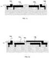
- FIGS. 1 a -1 ishow intermediate structures and respective fabrication processes in accordance with the invention. More specifically, the processes shown and described with reference to FIGS. 1 a -1 h are directed to the embodiment of FIG. 2 . However, it should be recognized by those of skill in the art that with some modifications and/or additions to the processes described herein, e.g., patterning, metallization and/or deposition processes, the processes of FIGS. 1 a -1 i can be used to fabricate any of the embodiments described herein. Although such modifications and/or additions should become obvious to those of skill in the art after an explanation of each of the embodiments, some further explanation of the additional and/or modified processes are described herein as necessary for a more thorough understanding of the invention.
- FIG. 1 ashows a beginning structure in accordance with the invention.
- the beginning structureincludes a dielectric material 10 with a plurality of vias 12 .
- the dielectric material 10may be an M+1 wiring layer in an integrated circuit.
- the dielectric material 10may be provided on a wafer of any known type used with the formation of integrated circuits.
- the wafercan be silicon, BULK, SOI, SiGe; quartz; glass; or Gallium arsenide, to name a few.
- the vias 12can be metallized using any combination of methods known in the art, such as physical vapor deposition (PVD), chemical vapor deposition (CVD), electroplated deposition (ECP), metal-organo chemical vapor deposition (MOCVD), etc.
- the viasare tungsten plugs, with TiN liners.
- the viasare formed using copper with TaN/Ta liners.
- the viasare ‘tapered vias’ which are metallized with the conductor layer used to form 16 a and 18 a shown in FIG. 1 b.
- the plurality of vias 12are formed using conventional lithographic processes. For example, a resist is deposited on the dielectric material 10 and selective portions of the resist are exposed to form openings. In subsequent processes, the dielectric material 10 is etched using a conventional process such as, for example, reactive ion etching (RIE) to form vias. The vias are filled with known metals or metal alloys to form the vias 12 . The resist can be stripped away. The vias 12 can act as conductive pads as noted in more detail below.
- RIEreactive ion etching
- the lower conductive MEMS switch electrodesare formed. These can be formed using any known method, such as by depositing the conductor, lithographically patterning it, etching it, and removing the photoresist used for lithographic patterning. Alternatively, other known methods, such as lift-off or damascene could be used.
- FIG. 1 bshows a damascene method in which a sacrificial resist layer 14 is deposited over the structure of FIG. 1 a .
- the sacrificial resist layer 14comprises Polymethylglutarimide (PMGI).
- PMGIis compatible with most g-line, i-line, and DUV photoresists and has excellent adhesion to Si, SiN, NiFe, Cu, Au, GaAs, and other III-V/III-VI materials.
- PMGIalso exhibits a high thermal stability and can be applied in any conventional manner such as, for example, spin-coating.
- the PMGIcan be stripped in NMP and DMSO-based removers.
- PMGIis DUV, E-beam, and x-ray sensitivity, as well as exhibits a high etch rate in oxygen plasma.
- the sacrificial resist layer 14is patterned to form openings.
- the openingsare filled with a metal such as gold; although, other metals or metal alloys are also contemplated by the invention such as AlCu, W, or Cu.
- a metalsuch as gold
- other metals or metal alloysare also contemplated by the invention such as AlCu, W, or Cu.
- one or more refractory metalssuch as Ti, TiN, Ta, TaN, Ru, etc. can be used to line the vias.
- the metalwill form fixed electrodes 16 a and 16 b and cantilevered electrodes 18 a and 18 b.
- FIGS. 1 c -1 fadditional deposition and patterning processes are sequentially shown to build the fixed electrodes 16 a and 16 b and cantilevered electrodes 18 a and 18 b .
- the deposition and patterning processesare similar to that described with reference to FIG. 1 b and, as such, additional explanation is not required for a complete understanding of the invention.
- the processes described hereinresult in the arm (beam) of the cantilever electrode 18 b being formed in the processes shown in FIG. 1 d and the arm of the cantilever electrode 18 a being formed in the processes shown in FIG. 1 f . Also, as shown in FIG.
- the electrodes 18 a and 18 bhave respective end portions 18 a 1 and 18 b 2 that overlap.
- the overlapping end portions 18 a 1 and 18 b 2upon application of a voltage, will close the switch, as discussed in greater detail below.
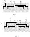
- a hermetic dielectric, such as Si 3 N 4 (nitride) liner 20is deposited over the structure of FIG. 1 h .
- the liner 20can be SiN.
- holes 22are etched into the liner 20 to form openings, exposing the sacrificial resist.
- a wet etching using, for example, NMP (N-methylpyrrolidone)is used to dissolve the sacrificial resist encapsulated within the liner 20 , creating a void 24 .
- the void 24is hermetically sealed by a deposition of Nitride 23 in order to close the holes 22 and form a hermetically sealed dome, as shown in FIG.
- the nitride domeis used to hermetically seal the MEMS switch and is optional.
- the method used for forming the freestanding cantilever beamsuses the sacrificial PMGI resist, any known method of forming cantilever beams, such as using sacrificial ⁇ -silicon, subtractive-etch wiring, tapered via wiring, etc. could also be used.
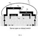
- FIG. 2shows a MEMS structure in accordance with a first aspect of the invention.
- the electrodes 16 a and 16 b and 18 a and 18 bare hermetically sealed within the nitride layer 25 .
- the nitride dome 25can be oval shaped, as shown in FIG. 2 , rectangular shaped, as shown in FIG. 1 , or any other known shape.
- the arms of the cantilever electrodes 18 a and 18 bare about 50 microns long, 9 microns high and 20 microns long; although other dimensions are also contemplated by the invention.
- a distance “X” between the respective overlapping end portions 18 a 1 and 18 b 2is about two microns; although, other distances are also contemplated by the invention.
- vertically extending portions(as shown in the embodiment of FIG. 5 ) can extend from each of the cantilever electrodes 18 a and 18 b.
- the cantilever electrode 18 aIn operation, upon the application of a positive voltage to the fixed electrode 16 a , the cantilever electrode 18 a will be pulled down towards the cantilever electrode 18 b . Also, upon a negative voltage applied to the fixed electrode 16 b , the cantilever electrode 18 b will be pushed up towards the cantilever electrode 18 a . At a predetermined designed voltage, the respective overlapping end portions 18 a 1 and 18 b 2 will make contact with one another, i.e., travel the distance “X”, thereby closing the switch. In the off state (0 voltage), the cantilever electrodes 18 a and 18 b will return to their original position, with a space “X” between the respective ends.
- the voltage applied to the fixed electrode 16 ais about 30 volts and the fixed electrode 16 b is about ⁇ 30 volts.
- This design voltagecan be significantly lower than known conventional systems as the two cantilever arms are each designed and arranged to move a smaller distance than a single arm in a conventional system. More specifically, there can be a reduced switching voltage due to bending of both arms and the use of two voltage electrodes (e.g., 16 a and 16 b ).
- This reduced voltageis a minimum switching voltage required to pull the electrodes together (i.e., pull-in voltage).
- This reduced voltagecan result in many advantages such as, for example, reduced on time voltage, unwanted charging on insulator and reduced failure of the switch (compared to known conventional switches).
- the MEMS switch of FIG. 2substantially eliminates arcing, as well as large dielectric breakdown attributable to higher switching voltages.
- FIG. 3shows a MEMS structure in accordance with a second aspect of the invention.
- the fixed electrode 16 bhas been eliminated.
- the fixed electrode 16 a and the cantilever electrodes 18 a and 18 bare hermetically sealed within the nitride layer 22 .
- the arms of the cantilever electrodes 18 a and 18 bare about 50 microns long, 9 microns high and 20 microns long; although other dimensions are also contemplated by the invention.
- a distance “X” between the overlapping respective end portions 18 a 1 and 18 b 1is about two microns; although, other distances are also contemplated by the invention.
- vertically extending portions(as shown in the embodiment of FIG. 5 ) can extend from one or both of the cantilever electrodes 18 a and 18 b.
- the cantilever electrode 18 aIn operation, upon the application of a positive voltage to the fixed electrode 16 a , the cantilever electrode 18 a will be pulled down towards the cantilever electrode 18 b . At a predetermined designed voltage, the respective overlapping end portions 18 a 1 and 18 b 1 will make contact with one another, i.e., travel the distance “X”, thereby closing the switch. In one design, the voltage applied to the fixed electrode 16 a is about 100 volts. In the off state (0 voltage), the cantilever electrode 18 a will return to its original position, with a space “X” between the respective end portions 18 a 1 and 18 b 2 . In this embodiment, the cantilever electrode 18 b is designed to remain stationary.
- This arrangementalso provides advantages such as, for example, reduced sticktion of the electrodes 18 a and 18 b . More specifically, as there are two cantilever arms 18 a and 18 b , it is theorized that that switch will stayed in the closed position, upon the application of a voltage, better than conventional MEMS switches. This will ensure that the switch will not fail.
- FIG. 4shows a MEMS structure in accordance with a third aspect of the invention.
- the electrodes 16 a and 16 b and 18 a and 18 bare hermetically sealed within the nitride layer 22 .
- the arms of the cantilever electrodes 18 a and 18 bhave different lengths, such that 18 b does not extent over 16 a , where the arm of the cantilever electrode 18 a is longer than the arm of the cantilever electrode 18 b (although this can be reversed).
- vertically extending portions(as shown in the embodiment of FIG. 5 ) can extend from one or both of the cantilever electrodes 18 a and 18 b.
- the arm of the cantilever electrode 18 aextends over both of the fixed electrodes 16 a and 16 b .
- the cantilever electrode 18 bis fixed, i.e., embedded, to the nitride layer 22 . This can be achieved by depositing the nitride layer 22 directly onto an upper surface of the cantilever electrode 18 b .
- the cantilever electrode 18 bcan also be floating by adding an upper layer of sacrificial material (PMGI) prior to the deposition of the nitride layer 22 .
- PMGIsacrificial material
- a distance “X” between the overlapping cantilevers 18 a and 18 bis about two microns; although, other distances are also contemplated by the invention.
- vertically extending portions(as shown in the embodiment of FIG. 5 ) can extend from the cantilever electrode 18 a or the fixed electrode 16 b.
- the cantilever electrode 18 aIn operation, upon the application of a positive voltage to the fixed electrode 16 a , the cantilever electrode 18 a will be pulled down towards the fixed electrode 16 b . Also, upon a negative voltage applied to the cantilever electrode 18 b , the cantilever electrode 18 a will be pushed down towards the fixed electrode 16 b . At a predetermined designed voltage, the end portion 18 a 1 will make contact with the fixed electrode 16 b , i.e., travel the distance “Y”, thereby closing the switch. In the off state (0 voltage), the cantilever electrode 18 a will return to its original position, with a space “Y” between the cantilever electrode 18 a and the fixed electrode 16 b . In this design, the cantilever electrode 18 b remains stationary, as it is fixed to the nitride liner 22 .
- the voltage applied to the fixed electrode 16 ais about 50 volts and the voltage applied to the cantilever electrode 18 b is about ⁇ 50 volts.
- This design voltagecan be significantly lower than known conventional systems as the arm of the cantilever electrode 18 a is being pushed and pulled by the use of two voltage electrodes (e.g., 16 a and 18 b ).
- This reduced voltageis a minimum switching voltage required to pull the electrodes together (i.e., pull-in voltage).
- This reduced voltagecan result in many advantages such as, for example, reduced on time voltage, unwanted charging on insulator and reduced failure of the switch (compared to known conventional switches).
- the MEMS switch of FIG. 4substantially eliminates arcing, as well as large dielectric breakdown attributable to higher switching voltages.
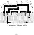
- FIG. 5shows a MEMS structure in accordance with a fourth aspect of the invention.
- an additional cantilever electrode 18 cis formed using the processes described above, e.g., adding an additional deposition layer of resist and additional patterning steps.
- the electrodes 16 a , 16 b and 18 a - 18 care hermetically sealed within the nitride layer 22 .
- the arm of the cantilever electrode 18 aalso includes a vertical extending protrusion (nub) 18 a 2 .
- the cantilever electrodes 18 a and 18 bare about 50 microns long, 9 microns high and 20 microns long; although other dimensions are also contemplated by the invention.
- a distance “X” between the respective portions 18 a 2 and 18 b 1is about two microns; although, other distances are also contemplated by the invention.
- vertically extending portionscan extend from each of the cantilever electrodes 18 a and 18 b.
- the cantilever electrode 18 bIn operation, upon the application of a positive voltage to the fixed electrode 16 b , the cantilever electrode 18 b will be pulled down towards the cantilever electrode 18 a . Also, upon a negative voltage applied to the fixed electrode 16 a and a positive voltage applied to the cantilever electrode 18 c , the cantilever electrode 18 a will be pushed upwards toward the cantilever electrode 18 b . At a predetermined designed voltage, the respective nub portion 18 a 2 and the end portion 18 b 1 will make contact with one another, i.e., travel the distance “X”, thereby closing the switch. In the off state (0 voltage), the cantilever electrodes 18 a and 18 b will return to their original position, with a space “X” between the respective ends.
- the voltage applied to the fixed electrode 16 b and the cantilever electrode 18 cis about 30 volts. Also, the voltage applied to the fixed electrode 16 a is about ⁇ 30 volts.
- This design voltagecan be significantly lower than known conventional systems as the two cantilever arms ( 18 a and 18 b ) are each designed and arranged to move a smaller distance than a single arm in a conventional system. More specifically, there can be a reduced switching voltage due to bending of both arms and the use of three voltage electrodes (e.g., 16 a , 16 b and 18 c ).
- This reduced voltageis a minimum switching voltage required to pull the electrodes together (i.e., pull-in voltage).
- This reduced voltagecan result in many advantages such as, for example, reduced on time voltage, unwanted charging on insulator and reduced failure of the switch (compared to known conventional switches).
- the MEMS switch of FIG. 5substantially eliminates arcing, as well as large dielectric breakdown attributable to higher switching voltages.
- FIG. 6shows a MEMS structure in accordance with a fifth aspect of the invention.
- an additional cantilever electrode 18 cis formed using the processes described above, e.g., adding an additional deposition layer of resist and additional patterning steps.
- the fixed electrode 16 bcan be raised to be closer to the cantilever electrode 18 b which, in turn, provides an improved response time (as the space between the fixed electrode 16 b and the cantilever electrode 18 b is closed).
- the height of the fixed electrode 16 bis higher than the height of the fixed electrode 16 a .
- a vertically extending portioncan also extend from the cantilever electrodes 18 b .
- a gapis approximately 5 to 10 microns between the electrode 16 b and the cantilever electrode 18 b .
- the electrodes 16 a , 16 b and 18 a - 18 care hermetically sealed within the nitride layer 22 .
- the arm of the cantilever electrode 18 aalso includes a vertical extending protrusion (nub) 18 a 2 .
- the cantilever electrodes 18 a and 18 bare about 50 microns long, 9 microns high and 20 microns long; although other dimensions are also contemplated by the invention.
- a distance “X” between the respective end portions 18 a 1 and 18 b 2 that overlapis about two microns; although, other distances are also contemplated by the invention.
- the cantilever electrode 18 bIn operation, upon the application of a positive voltage to the fixed electrode 16 b , the cantilever electrode 18 b will be pulled down towards the cantilever electrode 18 a . Also, upon a negative voltage applied to the fixed electrode 16 a and a positive voltage applied to the cantilever electrode 18 c , the cantilever electrode 18 a will be pushed upwards toward the cantilever electrode 18 b . At a predetermined designed voltage, the respective nub portion 18 a 2 and the end portion 18 b 1 will make contact with one another, i.e., travel the distance “X”, thereby closing the switch. In the off state (0 voltage), the cantilever electrodes 18 a and 18 b will return to their original position, with a space “X” between the respective ends.
- the voltage applied to the fixed electrode 16 b and the cantilever electrode 18 cis about 30 volts. Also, the voltage applied to the fixed electrode 16 a is about ⁇ 30 volts.
- This design voltagecan be significantly lower than known conventional systems as the two cantilever arms ( 18 a and 18 b ) are each designed and arranged to move a smaller distance, than a single arm in a conventional system. More specifically, there can be a reduced switching voltage due to bending of both arms and the use of three voltage electrodes (e.g., 16 a , 16 b and 18 c ).
- This reduced voltageis a minimum switching voltage required to pull the electrodes together (i.e., pull-in voltage).
- This reduced voltagecan result in many advantages such as, for example, reduced on time voltage, unwanted charging on insulator and reduced failure of the switch (compared to known conventional switches).
- the MEMS switch of FIG. 6substantially eliminates arcing, as well as large dielectric breakdown attributable to higher switching voltages.
- the structures as described aboveare used in the fabrication of integrated circuit chips.
- the resulting integrated circuit chipscan be distributed by the fabricator in raw wafer form (that is, as a single wafer that has multiple unpackaged chips), as a bare die, or in a packaged form.
- the chipis mounted in a single chip package (such as a plastic carrier, with leads that are affixed to a motherboard or other higher level carrier) or in a multichip package (such as a ceramic carrier that has either or both surface interconnections or buried interconnections).
- the chipis then integrated with other chips, discrete circuit elements, and/or other signal processing devices as part of either (a) an intermediate product, such as a motherboard, or (b) an end product.
- the end productcan be any product that includes integrated circuit chips, ranging from toys and other low-end applications to advanced computer products having a display, a keyboard or other input device, and a central processor.
Landscapes
- Engineering & Computer Science (AREA)
- Manufacturing & Machinery (AREA)
- Microelectronics & Electronic Packaging (AREA)
- Physics & Mathematics (AREA)
- Electromagnetism (AREA)
- Micromachines (AREA)
Abstract
Description
Claims (11)
Priority Applications (1)
| Application Number | Priority Date | Filing Date | Title |
|---|---|---|---|
| US15/717,187US10647569B2 (en) | 2008-04-22 | 2017-09-27 | Methods of manufacture for MEMS switches with reduced switching voltage |
Applications Claiming Priority (5)
| Application Number | Priority Date | Filing Date | Title |
|---|---|---|---|
| US12/107,118US8451077B2 (en) | 2008-04-22 | 2008-04-22 | MEMS switches with reduced switching voltage and methods of manufacture |
| US13/826,070US9019049B2 (en) | 2008-04-22 | 2013-03-14 | MEMS switches with reduced switching voltage and methods of manufacture |
| US14/670,671US9287075B2 (en) | 2008-04-22 | 2015-03-27 | MEMS switches with reduced switching voltage and methods of manufacture |
| US14/883,843US9944518B2 (en) | 2008-04-22 | 2015-10-15 | Method of manufacture MEMS switches with reduced voltage |
| US15/717,187US10647569B2 (en) | 2008-04-22 | 2017-09-27 | Methods of manufacture for MEMS switches with reduced switching voltage |
Related Parent Applications (1)
| Application Number | Title | Priority Date | Filing Date |
|---|---|---|---|
| US14/883,843ContinuationUS9944518B2 (en) | 2008-04-22 | 2015-10-15 | Method of manufacture MEMS switches with reduced voltage |
Publications (2)
| Publication Number | Publication Date |
|---|---|
| US20180016137A1 US20180016137A1 (en) | 2018-01-18 |
| US10647569B2true US10647569B2 (en) | 2020-05-12 |
Family
ID=41200209
Family Applications (13)
| Application Number | Title | Priority Date | Filing Date |
|---|---|---|---|
| US12/107,118Expired - Fee RelatedUS8451077B2 (en) | 2008-04-22 | 2008-04-22 | MEMS switches with reduced switching voltage and methods of manufacture |
| US13/826,070ActiveUS9019049B2 (en) | 2008-04-22 | 2013-03-14 | MEMS switches with reduced switching voltage and methods of manufacture |
| US14/670,671Expired - Fee RelatedUS9287075B2 (en) | 2008-04-22 | 2015-03-27 | MEMS switches with reduced switching voltage and methods of manufacture |
| US14/883,836Expired - Fee RelatedUS9824834B2 (en) | 2008-04-22 | 2015-10-15 | Method of manufacturing MEMS switches with reduced voltage |
| US14/883,745ActiveUS9944517B2 (en) | 2008-04-22 | 2015-10-15 | Method of manufacturing MEMS switches with reduced switching volume |
| US14/883,843ActiveUS9944518B2 (en) | 2008-04-22 | 2015-10-15 | Method of manufacture MEMS switches with reduced voltage |
| US14/883,825Active2028-07-13US10017383B2 (en) | 2008-04-22 | 2015-10-15 | Method of manufacturing MEMS switches with reduced switching voltage |
| US15/012,314Expired - Fee RelatedUS9718681B2 (en) | 2008-04-22 | 2016-02-01 | Method of manufacturing a switch |
| US15/627,673Expired - Fee RelatedUS10745273B2 (en) | 2008-04-22 | 2017-06-20 | Method of manufacturing a switch |
| US15/717,187Expired - Fee RelatedUS10647569B2 (en) | 2008-04-22 | 2017-09-27 | Methods of manufacture for MEMS switches with reduced switching voltage |
| US15/717,234Expired - Fee RelatedUS10640373B2 (en) | 2008-04-22 | 2017-09-27 | Methods of manufacturing for MEMS switches with reduced switching voltage |
| US15/807,661Expired - Fee RelatedUS10836632B2 (en) | 2008-04-22 | 2017-11-09 | Method of manufacturing MEMS switches with reduced switching voltage |
| US15/809,066Expired - Fee RelatedUS10941036B2 (en) | 2008-04-22 | 2017-11-10 | Method of manufacturing MEMS switches with reduced switching voltage |
Family Applications Before (9)
| Application Number | Title | Priority Date | Filing Date |
|---|---|---|---|
| US12/107,118Expired - Fee RelatedUS8451077B2 (en) | 2008-04-22 | 2008-04-22 | MEMS switches with reduced switching voltage and methods of manufacture |
| US13/826,070ActiveUS9019049B2 (en) | 2008-04-22 | 2013-03-14 | MEMS switches with reduced switching voltage and methods of manufacture |
| US14/670,671Expired - Fee RelatedUS9287075B2 (en) | 2008-04-22 | 2015-03-27 | MEMS switches with reduced switching voltage and methods of manufacture |
| US14/883,836Expired - Fee RelatedUS9824834B2 (en) | 2008-04-22 | 2015-10-15 | Method of manufacturing MEMS switches with reduced voltage |
| US14/883,745ActiveUS9944517B2 (en) | 2008-04-22 | 2015-10-15 | Method of manufacturing MEMS switches with reduced switching volume |
| US14/883,843ActiveUS9944518B2 (en) | 2008-04-22 | 2015-10-15 | Method of manufacture MEMS switches with reduced voltage |
| US14/883,825Active2028-07-13US10017383B2 (en) | 2008-04-22 | 2015-10-15 | Method of manufacturing MEMS switches with reduced switching voltage |
| US15/012,314Expired - Fee RelatedUS9718681B2 (en) | 2008-04-22 | 2016-02-01 | Method of manufacturing a switch |
| US15/627,673Expired - Fee RelatedUS10745273B2 (en) | 2008-04-22 | 2017-06-20 | Method of manufacturing a switch |
Family Applications After (3)
| Application Number | Title | Priority Date | Filing Date |
|---|---|---|---|
| US15/717,234Expired - Fee RelatedUS10640373B2 (en) | 2008-04-22 | 2017-09-27 | Methods of manufacturing for MEMS switches with reduced switching voltage |
| US15/807,661Expired - Fee RelatedUS10836632B2 (en) | 2008-04-22 | 2017-11-09 | Method of manufacturing MEMS switches with reduced switching voltage |
| US15/809,066Expired - Fee RelatedUS10941036B2 (en) | 2008-04-22 | 2017-11-10 | Method of manufacturing MEMS switches with reduced switching voltage |
Country Status (1)
| Country | Link |
|---|---|
| US (13) | US8451077B2 (en) |
Families Citing this family (11)
| Publication number | Priority date | Publication date | Assignee | Title |
|---|---|---|---|---|
| TWI444323B (en)* | 2010-02-03 | 2014-07-11 | Prime View Int Co Ltd | Driving memberand driving member array module |
| CN102211752A (en)* | 2010-04-08 | 2011-10-12 | 元太科技工业股份有限公司 | Drive element, drive element array module and its structure |
| US8635765B2 (en)* | 2011-06-15 | 2014-01-28 | International Business Machines Corporation | Method of forming micro-electrical-mechanical structure (MEMS) |
| US9165723B2 (en) | 2012-08-23 | 2015-10-20 | Harris Corporation | Switches for use in microelectromechanical and other systems, and processes for making same |
| US9053873B2 (en)* | 2012-09-20 | 2015-06-09 | Harris Corporation | Switches for use in microelectromechanical and other systems, and processes for making same |
| US10418918B2 (en)* | 2015-02-18 | 2019-09-17 | Sony Corporation | Electrostatic actuator, switch device and power supply device |
| CN106829852B (en)* | 2017-01-18 | 2018-05-04 | 中国科学院深圳先进技术研究院 | L-type electrostatic driving micro robot, manufacture method and control method |
| JP6950613B2 (en)* | 2018-04-11 | 2021-10-13 | Tdk株式会社 | Magnetically actuated MEMS switch |
| CN114444365B (en)* | 2022-04-08 | 2023-02-24 | 淄博高新技术产业开发区Mems研究院 | Method and system for calculating pull-in voltage of electrostatic driving micro actuator and storage medium |
| WO2023206154A1 (en)* | 2022-04-27 | 2023-11-02 | 京东方科技集团股份有限公司 | Mems switch and preparation method therefor, and electronic device |
| CN118098844B (en)* | 2024-04-22 | 2024-09-13 | 荣耀终端有限公司 | MEMS switch and electronic equipment |
Citations (67)
| Publication number | Priority date | Publication date | Assignee | Title |
|---|---|---|---|---|
| US3974468A (en) | 1974-02-07 | 1976-08-10 | Goran Ygfors | Contact carriers for relays |
| JPS5473508A (en) | 1977-11-24 | 1979-06-12 | Nec Corp | Multi-contact enclosure type electromagnetic switch |
| USRE33587E (en) | 1984-12-21 | 1991-05-14 | General Electric Company | Method for (prepolarizing and centering) operating a piezoceramic power switching device |
| US5430421A (en) | 1992-12-15 | 1995-07-04 | Asulab S.A. | Reed contactor and process of fabricating suspended tridimensional metallic microstructure |
| US5578976A (en) | 1995-06-22 | 1996-11-26 | Rockwell International Corporation | Micro electromechanical RF switch |
| JPH10134683A (en) | 1996-11-02 | 1998-05-22 | Ubukata Seisakusho:Kk | Thermally-actuated switch |
| JPH11162309A (en) | 1997-11-26 | 1999-06-18 | Fujitsu Takamisawa Component Ltd | Reed switch and reed relay |
| US6046659A (en) | 1998-05-15 | 2000-04-04 | Hughes Electronics Corporation | Design and fabrication of broadband surface-micromachined micro-electro-mechanical switches for microwave and millimeter-wave applications |
| US6054745A (en) | 1999-01-04 | 2000-04-25 | International Business Machines Corporation | Nonvolatile memory cell using microelectromechanical device |
| US6127744A (en) | 1998-11-23 | 2000-10-03 | Raytheon Company | Method and apparatus for an improved micro-electrical mechanical switch |
| US6143997A (en) | 1999-06-04 | 2000-11-07 | The Board Of Trustees Of The University Of Illinois | Low actuation voltage microelectromechanical device and method of manufacture |
| US6276205B1 (en) | 1998-09-12 | 2001-08-21 | The Secretary Of State For Defence In Her Britanic Majesty's Government Of The United Kingdom Of Great Britain And Northern Ireland | Micro-machining |
| US6310526B1 (en) | 1999-09-21 | 2001-10-30 | Lap-Sum Yip | Double-throw miniature electromagnetic microwave (MEM) switches |
| US6373007B1 (en) | 2000-04-19 | 2002-04-16 | The United States Of America As Represented By The Secretary Of The Air Force | Series and shunt mems RF switch |
| US6384353B1 (en) | 2000-02-01 | 2002-05-07 | Motorola, Inc. | Micro-electromechanical system device |
| US6410360B1 (en) | 1999-01-26 | 2002-06-25 | Teledyne Industries, Inc. | Laminate-based apparatus and method of fabrication |
| US6426687B1 (en) | 2001-05-22 | 2002-07-30 | The Aerospace Corporation | RF MEMS switch |
| US20020131228A1 (en) | 2001-03-13 | 2002-09-19 | Potter Michael D. | Micro-electro-mechanical switch and a method of using and making thereof |
| US6465280B1 (en) | 2001-03-07 | 2002-10-15 | Analog Devices, Inc. | In-situ cap and method of fabricating same for an integrated circuit device |
| US6469603B1 (en) | 1999-09-23 | 2002-10-22 | Arizona State University | Electronically switching latching micro-magnetic relay and method of operating same |
| US20020158746A1 (en) | 2000-12-04 | 2002-10-31 | Texas Instruments Incorporated | Hermetic single phase motor protector |
| US6529093B2 (en)* | 2001-07-06 | 2003-03-04 | Intel Corporation | Microelectromechanical (MEMS) switch using stepped actuation electrodes |
| US20030080839A1 (en) | 2001-10-31 | 2003-05-01 | Wong Marvin Glenn | Method for improving the power handling capacity of MEMS switches |
| US6570750B1 (en) | 2000-04-19 | 2003-05-27 | The United States Of America As Represented By The Secretary Of The Air Force | Shunted multiple throw MEMS RF switch |
| US20030116417A1 (en) | 2001-11-09 | 2003-06-26 | Coventor, Inc. | MEMS device having contact and standoff bumps and related methods |
| US20030122640A1 (en) | 2001-12-31 | 2003-07-03 | International Business Machines Corporation | Lateral microelectromechanical system switch |
| US20030132823A1 (en) | 2000-10-27 | 2003-07-17 | Hyman Daniel J. | Microfabricated double-throw relay with multimorph actuator and electrostatic latch mechanism |
| US20030151479A1 (en) | 2001-09-17 | 2003-08-14 | John Stafford | Latching micro magnetic relay packages and methods of packaging |
| US6621390B2 (en) | 2001-02-28 | 2003-09-16 | Samsung Electronics Co., Ltd. | Electrostatically-actuated capacitive MEMS (micro electro mechanical system) switch |
| US20030210116A1 (en) | 2002-05-08 | 2003-11-13 | Motorola, Inc. | Micro electro-mechanical system with one or more moving parts method and apparatus |
| US6657324B1 (en) | 1999-04-27 | 2003-12-02 | Nec Corporation | Micromachine switch and method of manufacture thereof |
| US20030222740A1 (en) | 2002-03-18 | 2003-12-04 | Microlab, Inc. | Latching micro-magnetic switch with improved thermal reliability |
| US6750742B2 (en) | 2002-11-01 | 2004-06-15 | Electronics And Telecommunications Research Institute | Radio frequency device using micro-electronic-mechanical system technology |
| US20040113727A1 (en) | 2002-12-12 | 2004-06-17 | Murata Manufacturing Co., Ltd. | RF-mems switch |
| US6761829B2 (en) | 2001-04-26 | 2004-07-13 | Rockwell Automation Technologies, Inc. | Method for fabricating an isolated microelectromechanical system (MEMS) device using an internal void |
| US6768403B2 (en) | 2002-03-12 | 2004-07-27 | Hrl Laboratories, Llc | Torsion spring for electro-mechanical switches and a cantilever-type RF micro-electromechanical switch incorporating the torsion spring |
| US6798315B2 (en) | 2001-12-04 | 2004-09-28 | Mayo Foundation For Medical Education And Research | Lateral motion MEMS Switch |
| JP2004327441A (en)* | 2003-04-25 | 2004-11-18 | Lg Electronics Inc | Low voltage micro switch |
| US6833985B2 (en) | 2002-03-08 | 2004-12-21 | Murata Manufacturing Co., Ltd. | Variable capacitance element |
| US6841839B2 (en) | 2002-09-24 | 2005-01-11 | Maxim Integrated Products, Inc. | Microrelays and microrelay fabrication and operating methods |
| US20050007219A1 (en) | 2002-07-11 | 2005-01-13 | Qing Ma | Microelectromechanical (MEMS) switching apparatus |
| US20050057329A1 (en) | 2003-09-17 | 2005-03-17 | Magfusion, Inc. | Laminated relays with multiple flexible contacts |
| US6891454B1 (en) | 2002-07-26 | 2005-05-10 | Matsushita Electric Industrial Co., Ltd. | Switch |
| US20050099252A1 (en) | 2003-11-10 | 2005-05-12 | Hitachi Media Electronics Co., Ltd. | RF-MEMS switch and its fabrication method |
| US6894592B2 (en) | 2001-05-18 | 2005-05-17 | Magfusion, Inc. | Micromagnetic latching switch packaging |
| US20050121298A1 (en) | 2002-09-24 | 2005-06-09 | Uppili Sridhar | Microrelays and microrelay fabrication and operating methods |
| US20050168306A1 (en) | 2000-11-29 | 2005-08-04 | Cohn Michael B. | MEMS device with integral packaging |
| US7042319B2 (en) | 2001-08-16 | 2006-05-09 | Denso Corporation | Thin film electromagnet and switching device comprising it |
| US20060181379A1 (en) | 2001-09-21 | 2006-08-17 | Hrl Laboratories, Llc | Stress bimorph MEMS switches and methods of making same |
| US7145213B1 (en) | 2004-05-24 | 2006-12-05 | The United States Of America As Represented By The Secretary Of The Air Force | MEMS RF switch integrated process |
| US20070040637A1 (en) | 2005-08-19 | 2007-02-22 | Yee Ian Y K | Microelectromechanical switches having mechanically active components which are electrically isolated from components of the switch used for the transmission of signals |
| US7250838B2 (en) | 2002-01-08 | 2007-07-31 | Schneider Electric Industries Sas | Packaging of a micro-magnetic switch with a patterned permanent magnet |
| JP2007207498A (en) | 2006-01-31 | 2007-08-16 | Oki Sensor Device Corp | Mechanism device |
| US7265429B2 (en) | 2002-08-07 | 2007-09-04 | Chang-Feng Wan | System and method of fabricating micro cavities |
| US20070236307A1 (en) | 2006-04-10 | 2007-10-11 | Lianjun Liu | Methods and apparatus for a packaged MEMS switch |
| US7299538B2 (en) | 2002-07-18 | 2007-11-27 | Wispry, Inc. | Method for fabricating micro-electro-mechanical systems |
| US7372348B2 (en) | 2004-08-20 | 2008-05-13 | Palo Alto Research Center Incorporated | Stressed material and shape memory material MEMS devices and methods for manufacturing |
| US7477884B2 (en) | 2005-04-08 | 2009-01-13 | Samsung Electronics Co., Ltd. | Tri-state RF switch |
| US7653985B1 (en) | 2004-10-07 | 2010-02-02 | Hrl Laboratories, Llc | Method of fabricating an RF MEMS switch with spring-loaded latching mechanism |
| US7692519B2 (en) | 2007-12-21 | 2010-04-06 | General Electric Company | MEMS switch with improved standoff voltage control |
| US7759591B2 (en) | 2005-12-15 | 2010-07-20 | Samsung Electronics Co., Ltd. | Pneumatic MEMS switch and method of fabricating the same |
| US8159056B1 (en) | 2008-01-15 | 2012-04-17 | Rf Micro Devices, Inc. | Package for an electronic device |
| US20120318650A1 (en) | 2007-12-13 | 2012-12-20 | Dimitrios Peroulis | Low-cost process-independent rf mems switch |
| US8450625B2 (en) | 2009-09-28 | 2013-05-28 | Kabushiki Kaisha Toshiba | Switch device and circuit including switch device |
| US8736404B2 (en) | 2009-10-01 | 2014-05-27 | Cavendish Kinetics Inc. | Micromechanical digital capacitor with improved RF hot switching performance and reliability |
| US8791778B2 (en) | 2009-04-20 | 2014-07-29 | International Business Machines Corporation | Vertical integrated circuit switches, design structure and methods of fabricating same |
| US9123493B2 (en) | 2014-01-23 | 2015-09-01 | Harris Corporation | Microelectromechanical switches for steering of RF signals |
Family Cites Families (8)
| Publication number | Priority date | Publication date | Assignee | Title |
|---|---|---|---|---|
| JP2867314B2 (en)* | 1993-12-30 | 1999-03-08 | 松尾電器産業株式会社 | Cantilever switchgear |
| GB2291769A (en) | 1994-07-27 | 1996-01-31 | Motorola Inc | Bidirectional communication system using volatage and current signals |
| US6495905B2 (en) | 2000-11-09 | 2002-12-17 | Texas Instruments Incorporated | Nanomechanical switches and circuits |
| DE10159821A1 (en)* | 2001-12-06 | 2003-06-18 | Basf Ag | Device and method for carrying out heterogeneously catalyzed reactive distillation, in particular for producing pseudo ions |
| US6940363B2 (en) | 2002-12-17 | 2005-09-06 | Intel Corporation | Switch architecture using MEMS switches and solid state switches in parallel |
| JP4561072B2 (en) | 2003-09-30 | 2010-10-13 | 株式会社日立製作所 | Semiconductor device having MEMS switch |
| US7233776B2 (en) | 2004-06-29 | 2007-06-19 | Intel Corporation | Low voltage microelectromechanical RF switch architecture |
| US7602261B2 (en) | 2005-12-22 | 2009-10-13 | Intel Corporation | Micro-electromechanical system (MEMS) switch |
- 2008
- 2008-04-22USUS12/107,118patent/US8451077B2/ennot_activeExpired - Fee Related
- 2013
- 2013-03-14USUS13/826,070patent/US9019049B2/enactiveActive
- 2015
- 2015-03-27USUS14/670,671patent/US9287075B2/ennot_activeExpired - Fee Related
- 2015-10-15USUS14/883,836patent/US9824834B2/ennot_activeExpired - Fee Related
- 2015-10-15USUS14/883,745patent/US9944517B2/enactiveActive
- 2015-10-15USUS14/883,843patent/US9944518B2/enactiveActive
- 2015-10-15USUS14/883,825patent/US10017383B2/enactiveActive
- 2016
- 2016-02-01USUS15/012,314patent/US9718681B2/ennot_activeExpired - Fee Related
- 2017
- 2017-06-20USUS15/627,673patent/US10745273B2/ennot_activeExpired - Fee Related
- 2017-09-27USUS15/717,187patent/US10647569B2/ennot_activeExpired - Fee Related
- 2017-09-27USUS15/717,234patent/US10640373B2/ennot_activeExpired - Fee Related
- 2017-11-09USUS15/807,661patent/US10836632B2/ennot_activeExpired - Fee Related
- 2017-11-10USUS15/809,066patent/US10941036B2/ennot_activeExpired - Fee Related
Patent Citations (74)
| Publication number | Priority date | Publication date | Assignee | Title |
|---|---|---|---|---|
| US3974468A (en) | 1974-02-07 | 1976-08-10 | Goran Ygfors | Contact carriers for relays |
| JPS5473508A (en) | 1977-11-24 | 1979-06-12 | Nec Corp | Multi-contact enclosure type electromagnetic switch |
| USRE33587E (en) | 1984-12-21 | 1991-05-14 | General Electric Company | Method for (prepolarizing and centering) operating a piezoceramic power switching device |
| US5430421A (en) | 1992-12-15 | 1995-07-04 | Asulab S.A. | Reed contactor and process of fabricating suspended tridimensional metallic microstructure |
| US5578976A (en) | 1995-06-22 | 1996-11-26 | Rockwell International Corporation | Micro electromechanical RF switch |
| JPH10134683A (en) | 1996-11-02 | 1998-05-22 | Ubukata Seisakusho:Kk | Thermally-actuated switch |
| JPH11162309A (en) | 1997-11-26 | 1999-06-18 | Fujitsu Takamisawa Component Ltd | Reed switch and reed relay |
| US6046659A (en) | 1998-05-15 | 2000-04-04 | Hughes Electronics Corporation | Design and fabrication of broadband surface-micromachined micro-electro-mechanical switches for microwave and millimeter-wave applications |
| US6276205B1 (en) | 1998-09-12 | 2001-08-21 | The Secretary Of State For Defence In Her Britanic Majesty's Government Of The United Kingdom Of Great Britain And Northern Ireland | Micro-machining |
| US6127744A (en) | 1998-11-23 | 2000-10-03 | Raytheon Company | Method and apparatus for an improved micro-electrical mechanical switch |
| US6054745A (en) | 1999-01-04 | 2000-04-25 | International Business Machines Corporation | Nonvolatile memory cell using microelectromechanical device |
| US6410360B1 (en) | 1999-01-26 | 2002-06-25 | Teledyne Industries, Inc. | Laminate-based apparatus and method of fabrication |
| US6657324B1 (en) | 1999-04-27 | 2003-12-02 | Nec Corporation | Micromachine switch and method of manufacture thereof |
| US6143997A (en) | 1999-06-04 | 2000-11-07 | The Board Of Trustees Of The University Of Illinois | Low actuation voltage microelectromechanical device and method of manufacture |
| US6310526B1 (en) | 1999-09-21 | 2001-10-30 | Lap-Sum Yip | Double-throw miniature electromagnetic microwave (MEM) switches |
| US6469603B1 (en) | 1999-09-23 | 2002-10-22 | Arizona State University | Electronically switching latching micro-magnetic relay and method of operating same |
| US6384353B1 (en) | 2000-02-01 | 2002-05-07 | Motorola, Inc. | Micro-electromechanical system device |
| US6373007B1 (en) | 2000-04-19 | 2002-04-16 | The United States Of America As Represented By The Secretary Of The Air Force | Series and shunt mems RF switch |
| US6570750B1 (en) | 2000-04-19 | 2003-05-27 | The United States Of America As Represented By The Secretary Of The Air Force | Shunted multiple throw MEMS RF switch |
| US20040207498A1 (en) | 2000-10-27 | 2004-10-21 | Xcom Wireless, Inc. | Microfabricated double-throw relay with multimorph actuator and electrostatic latch mechanism |
| US20030132823A1 (en) | 2000-10-27 | 2003-07-17 | Hyman Daniel J. | Microfabricated double-throw relay with multimorph actuator and electrostatic latch mechanism |
| US20050168306A1 (en) | 2000-11-29 | 2005-08-04 | Cohn Michael B. | MEMS device with integral packaging |
| US20020158746A1 (en) | 2000-12-04 | 2002-10-31 | Texas Instruments Incorporated | Hermetic single phase motor protector |
| US6621390B2 (en) | 2001-02-28 | 2003-09-16 | Samsung Electronics Co., Ltd. | Electrostatically-actuated capacitive MEMS (micro electro mechanical system) switch |
| US6465280B1 (en) | 2001-03-07 | 2002-10-15 | Analog Devices, Inc. | In-situ cap and method of fabricating same for an integrated circuit device |
| US7280014B2 (en) | 2001-03-13 | 2007-10-09 | Rochester Institute Of Technology | Micro-electro-mechanical switch and a method of using and making thereof |
| US20020131228A1 (en) | 2001-03-13 | 2002-09-19 | Potter Michael D. | Micro-electro-mechanical switch and a method of using and making thereof |
| US6761829B2 (en) | 2001-04-26 | 2004-07-13 | Rockwell Automation Technologies, Inc. | Method for fabricating an isolated microelectromechanical system (MEMS) device using an internal void |
| US6894592B2 (en) | 2001-05-18 | 2005-05-17 | Magfusion, Inc. | Micromagnetic latching switch packaging |
| US6426687B1 (en) | 2001-05-22 | 2002-07-30 | The Aerospace Corporation | RF MEMS switch |
| US6529093B2 (en)* | 2001-07-06 | 2003-03-04 | Intel Corporation | Microelectromechanical (MEMS) switch using stepped actuation electrodes |
| US7042319B2 (en) | 2001-08-16 | 2006-05-09 | Denso Corporation | Thin film electromagnet and switching device comprising it |
| US20030151479A1 (en) | 2001-09-17 | 2003-08-14 | John Stafford | Latching micro magnetic relay packages and methods of packaging |
| US20060181379A1 (en) | 2001-09-21 | 2006-08-17 | Hrl Laboratories, Llc | Stress bimorph MEMS switches and methods of making same |
| US20030080839A1 (en) | 2001-10-31 | 2003-05-01 | Wong Marvin Glenn | Method for improving the power handling capacity of MEMS switches |
| US20030116417A1 (en) | 2001-11-09 | 2003-06-26 | Coventor, Inc. | MEMS device having contact and standoff bumps and related methods |
| US6876047B2 (en) | 2001-11-09 | 2005-04-05 | Turnstone Systems, Inc. | MEMS device having a trilayered beam and related methods |
| US6798315B2 (en) | 2001-12-04 | 2004-09-28 | Mayo Foundation For Medical Education And Research | Lateral motion MEMS Switch |
| US6977569B2 (en) | 2001-12-31 | 2005-12-20 | International Business Machines Corporation | Lateral microelectromechanical system switch |
| US20030122640A1 (en) | 2001-12-31 | 2003-07-03 | International Business Machines Corporation | Lateral microelectromechanical system switch |
| US6917268B2 (en) | 2001-12-31 | 2005-07-12 | International Business Machines Corporation | Lateral microelectromechanical system switch |
| US7250838B2 (en) | 2002-01-08 | 2007-07-31 | Schneider Electric Industries Sas | Packaging of a micro-magnetic switch with a patterned permanent magnet |
| US6833985B2 (en) | 2002-03-08 | 2004-12-21 | Murata Manufacturing Co., Ltd. | Variable capacitance element |
| US6768403B2 (en) | 2002-03-12 | 2004-07-27 | Hrl Laboratories, Llc | Torsion spring for electro-mechanical switches and a cantilever-type RF micro-electromechanical switch incorporating the torsion spring |
| US20030222740A1 (en) | 2002-03-18 | 2003-12-04 | Microlab, Inc. | Latching micro-magnetic switch with improved thermal reliability |
| US20030210116A1 (en) | 2002-05-08 | 2003-11-13 | Motorola, Inc. | Micro electro-mechanical system with one or more moving parts method and apparatus |
| US20050007219A1 (en) | 2002-07-11 | 2005-01-13 | Qing Ma | Microelectromechanical (MEMS) switching apparatus |
| US7299538B2 (en) | 2002-07-18 | 2007-11-27 | Wispry, Inc. | Method for fabricating micro-electro-mechanical systems |
| US6891454B1 (en) | 2002-07-26 | 2005-05-10 | Matsushita Electric Industrial Co., Ltd. | Switch |
| US7265429B2 (en) | 2002-08-07 | 2007-09-04 | Chang-Feng Wan | System and method of fabricating micro cavities |
| US20050121298A1 (en) | 2002-09-24 | 2005-06-09 | Uppili Sridhar | Microrelays and microrelay fabrication and operating methods |
| US7463125B2 (en) | 2002-09-24 | 2008-12-09 | Maxim Integrated Products, Inc. | Microrelays and microrelay fabrication and operating methods |
| US6841839B2 (en) | 2002-09-24 | 2005-01-11 | Maxim Integrated Products, Inc. | Microrelays and microrelay fabrication and operating methods |
| US6750742B2 (en) | 2002-11-01 | 2004-06-15 | Electronics And Telecommunications Research Institute | Radio frequency device using micro-electronic-mechanical system technology |
| US20040113727A1 (en) | 2002-12-12 | 2004-06-17 | Murata Manufacturing Co., Ltd. | RF-mems switch |
| JP2004327441A (en)* | 2003-04-25 | 2004-11-18 | Lg Electronics Inc | Low voltage micro switch |
| US20050057329A1 (en) | 2003-09-17 | 2005-03-17 | Magfusion, Inc. | Laminated relays with multiple flexible contacts |
| US7215229B2 (en) | 2003-09-17 | 2007-05-08 | Schneider Electric Industries Sas | Laminated relays with multiple flexible contacts |
| US20050099252A1 (en) | 2003-11-10 | 2005-05-12 | Hitachi Media Electronics Co., Ltd. | RF-MEMS switch and its fabrication method |
| US7145213B1 (en) | 2004-05-24 | 2006-12-05 | The United States Of America As Represented By The Secretary Of The Air Force | MEMS RF switch integrated process |
| US7372348B2 (en) | 2004-08-20 | 2008-05-13 | Palo Alto Research Center Incorporated | Stressed material and shape memory material MEMS devices and methods for manufacturing |
| US7653985B1 (en) | 2004-10-07 | 2010-02-02 | Hrl Laboratories, Llc | Method of fabricating an RF MEMS switch with spring-loaded latching mechanism |
| US7477884B2 (en) | 2005-04-08 | 2009-01-13 | Samsung Electronics Co., Ltd. | Tri-state RF switch |
| US20070040637A1 (en) | 2005-08-19 | 2007-02-22 | Yee Ian Y K | Microelectromechanical switches having mechanically active components which are electrically isolated from components of the switch used for the transmission of signals |
| US7759591B2 (en) | 2005-12-15 | 2010-07-20 | Samsung Electronics Co., Ltd. | Pneumatic MEMS switch and method of fabricating the same |
| JP2007207498A (en) | 2006-01-31 | 2007-08-16 | Oki Sensor Device Corp | Mechanism device |
| US20070236307A1 (en) | 2006-04-10 | 2007-10-11 | Lianjun Liu | Methods and apparatus for a packaged MEMS switch |
| US20120318650A1 (en) | 2007-12-13 | 2012-12-20 | Dimitrios Peroulis | Low-cost process-independent rf mems switch |
| US7692519B2 (en) | 2007-12-21 | 2010-04-06 | General Electric Company | MEMS switch with improved standoff voltage control |
| US8159056B1 (en) | 2008-01-15 | 2012-04-17 | Rf Micro Devices, Inc. | Package for an electronic device |
| US8791778B2 (en) | 2009-04-20 | 2014-07-29 | International Business Machines Corporation | Vertical integrated circuit switches, design structure and methods of fabricating same |
| US8450625B2 (en) | 2009-09-28 | 2013-05-28 | Kabushiki Kaisha Toshiba | Switch device and circuit including switch device |
| US8736404B2 (en) | 2009-10-01 | 2014-05-27 | Cavendish Kinetics Inc. | Micromechanical digital capacitor with improved RF hot switching performance and reliability |
| US9123493B2 (en) | 2014-01-23 | 2015-09-01 | Harris Corporation | Microelectromechanical switches for steering of RF signals |
Non-Patent Citations (10)
| Title |
|---|
| Final Office Action dated Dec. 27, 2017 in related U.S. Appl. No. 14/883,825, 13 pages. |
| Notice of Allowance dated Dec. 15, 2017 in related U.S. Appl. No. 14/883,745, 12 pages. |
| Notice of Allowance dated Dec. 15, 2017 in related U.S. Appl. No. 14/883,843, 14 pages. |
| Notice of Allowance dated Dec. 27, 2019 in related U.S. Appl. No. 15/717,234, 7 pages. |
| Notice of Allowance dated Mar. 5, 2018 in related U.S. Appl. No. 14/883,825, 7 pages. |
| Notice of Allowance dated May 29, 2019 in related U.S. Appl. No. 15/627,673, 6 pages. |
| Office Action dated Jun. 26, 2019 in related U.S. Appl. No. 15/717,234, 12 pages. |
| Office Action dated Nov. 29, 2018 for related U.S. Appl. No. 15/627,673, 11 pages. |
| Office Action dated Oct. 21, 2019 in related U.S. Appl. No. 15/807,661, 10 pages. |
| Office Action dated Oct. 4, 2019 in related U.S. Appl. No. 15/809,066, 11 pages. |
Also Published As
| Publication number | Publication date |
|---|---|
| US20090260961A1 (en) | 2009-10-22 |
| US9944517B2 (en) | 2018-04-17 |
| US9287075B2 (en) | 2016-03-15 |
| US9019049B2 (en) | 2015-04-28 |
| US20180016138A1 (en) | 2018-01-18 |
| US8451077B2 (en) | 2013-05-28 |
| US20160145097A1 (en) | 2016-05-26 |
| US9718681B2 (en) | 2017-08-01 |
| US20160035511A1 (en) | 2016-02-04 |
| US20160035513A1 (en) | 2016-02-04 |
| US10941036B2 (en) | 2021-03-09 |
| US20130192964A1 (en) | 2013-08-01 |
| US10745273B2 (en) | 2020-08-18 |
| US9944518B2 (en) | 2018-04-17 |
| US20150200069A1 (en) | 2015-07-16 |
| US20160035510A1 (en) | 2016-02-04 |
| US9824834B2 (en) | 2017-11-21 |
| US10836632B2 (en) | 2020-11-17 |
| US20160035512A1 (en) | 2016-02-04 |
| US10640373B2 (en) | 2020-05-05 |
| US20180065847A1 (en) | 2018-03-08 |
| US10017383B2 (en) | 2018-07-10 |
| US20180093884A1 (en) | 2018-04-05 |
| US20170294274A1 (en) | 2017-10-12 |
| US20180016137A1 (en) | 2018-01-18 |
Similar Documents
| Publication | Publication Date | Title |
|---|---|---|
| US10941036B2 (en) | Method of manufacturing MEMS switches with reduced switching voltage | |
| US9284185B2 (en) | Integrated circuit switches, design structure and methods of fabricating the same | |
| US8748207B2 (en) | Hybrid MEMS RF switch and method of fabricating same | |
| US8791778B2 (en) | Vertical integrated circuit switches, design structure and methods of fabricating same | |
| US10589992B2 (en) | Micro-electro-mechanical system (MEMS) structures and design structures | |
| US8609450B2 (en) | MEMS switches and fabrication methods | |
| US8878315B2 (en) | Horizontal coplanar switches and methods of manufacture |
Legal Events
| Date | Code | Title | Description |
|---|---|---|---|
| AS | Assignment | Owner name:INTERNATIONAL BUSINESS MACHINES CORPORATION, NEW YORK Free format text:ASSIGNMENT OF ASSIGNORS INTEREST;ASSIGNORS:LUCE, STEPHEN E.;STAMPER, ANTHONY K.;SIGNING DATES FROM 20130227 TO 20130312;REEL/FRAME:043716/0396 Owner name:INTERNATIONAL BUSINESS MACHINES CORPORATION, NEW Y Free format text:ASSIGNMENT OF ASSIGNORS INTEREST;ASSIGNORS:LUCE, STEPHEN E.;STAMPER, ANTHONY K.;SIGNING DATES FROM 20130227 TO 20130312;REEL/FRAME:043716/0396 | |
| FEPP | Fee payment procedure | Free format text:ENTITY STATUS SET TO UNDISCOUNTED (ORIGINAL EVENT CODE: BIG.); ENTITY STATUS OF PATENT OWNER: LARGE ENTITY | |
| STPP | Information on status: patent application and granting procedure in general | Free format text:DOCKETED NEW CASE - READY FOR EXAMINATION | |
| STPP | Information on status: patent application and granting procedure in general | Free format text:NON FINAL ACTION MAILED | |
| STPP | Information on status: patent application and granting procedure in general | Free format text:RESPONSE TO NON-FINAL OFFICE ACTION ENTERED AND FORWARDED TO EXAMINER | |
| STPP | Information on status: patent application and granting procedure in general | Free format text:NOTICE OF ALLOWANCE MAILED -- APPLICATION RECEIVED IN OFFICE OF PUBLICATIONS | |
| ZAAA | Notice of allowance and fees due | Free format text:ORIGINAL CODE: NOA | |
| ZAAB | Notice of allowance mailed | Free format text:ORIGINAL CODE: MN/=. | |
| STCF | Information on status: patent grant | Free format text:PATENTED CASE | |
| FEPP | Fee payment procedure | Free format text:MAINTENANCE FEE REMINDER MAILED (ORIGINAL EVENT CODE: REM.); ENTITY STATUS OF PATENT OWNER: LARGE ENTITY | |
| LAPS | Lapse for failure to pay maintenance fees | Free format text:PATENT EXPIRED FOR FAILURE TO PAY MAINTENANCE FEES (ORIGINAL EVENT CODE: EXP.); ENTITY STATUS OF PATENT OWNER: LARGE ENTITY | |
| STCH | Information on status: patent discontinuation | Free format text:PATENT EXPIRED DUE TO NONPAYMENT OF MAINTENANCE FEES UNDER 37 CFR 1.362 | |
| FP | Lapsed due to failure to pay maintenance fee | Effective date:20240512 |