US10646235B2 - Guide wire seal for reamer irrigator aspirator system - Google Patents
Guide wire seal for reamer irrigator aspirator systemDownload PDFInfo
- Publication number
- US10646235B2 US10646235B2US15/794,115US201715794115AUS10646235B2US 10646235 B2US10646235 B2US 10646235B2US 201715794115 AUS201715794115 AUS 201715794115AUS 10646235 B2US10646235 B2US 10646235B2
- Authority
- US
- United States
- Prior art keywords
- drive shaft
- seal
- carrier
- proximal end
- reamer
- Prior art date
- Legal status (The legal status is an assumption and is not a legal conclusion. Google has not performed a legal analysis and makes no representation as to the accuracy of the status listed.)
- Active, expires
Links
Images


Classifications
- A—HUMAN NECESSITIES
- A61—MEDICAL OR VETERINARY SCIENCE; HYGIENE
- A61B—DIAGNOSIS; SURGERY; IDENTIFICATION
- A61B17/00—Surgical instruments, devices or methods
- A61B17/16—Instruments for performing osteoclasis; Drills or chisels for bones; Trepans
- A61B17/164—Instruments for performing osteoclasis; Drills or chisels for bones; Trepans intramedullary
- A—HUMAN NECESSITIES
- A61—MEDICAL OR VETERINARY SCIENCE; HYGIENE
- A61B—DIAGNOSIS; SURGERY; IDENTIFICATION
- A61B17/00—Surgical instruments, devices or methods
- A61B17/16—Instruments for performing osteoclasis; Drills or chisels for bones; Trepans
- A61B17/1613—Component parts
- A61B17/1615—Drill bits, i.e. rotating tools extending from a handpiece to contact the worked material
- A—HUMAN NECESSITIES
- A61—MEDICAL OR VETERINARY SCIENCE; HYGIENE
- A61B—DIAGNOSIS; SURGERY; IDENTIFICATION
- A61B17/00—Surgical instruments, devices or methods
- A61B17/16—Instruments for performing osteoclasis; Drills or chisels for bones; Trepans
- A61B17/1613—Component parts
- A61B17/1631—Special drive shafts, e.g. flexible shafts
- A—HUMAN NECESSITIES
- A61—MEDICAL OR VETERINARY SCIENCE; HYGIENE
- A61B—DIAGNOSIS; SURGERY; IDENTIFICATION
- A61B17/00—Surgical instruments, devices or methods
- A61B17/16—Instruments for performing osteoclasis; Drills or chisels for bones; Trepans
- A61B17/1613—Component parts
- A61B17/1633—Sleeves, i.e. non-rotating parts surrounding the bit shaft, e.g. the sleeve forming a single unit with the bit shaft
- A—HUMAN NECESSITIES
- A61—MEDICAL OR VETERINARY SCIENCE; HYGIENE
- A61B—DIAGNOSIS; SURGERY; IDENTIFICATION
- A61B17/00—Surgical instruments, devices or methods
- A61B17/16—Instruments for performing osteoclasis; Drills or chisels for bones; Trepans
- A61B17/1644—Instruments for performing osteoclasis; Drills or chisels for bones; Trepans using fluid other than turbine drive fluid
- A61B17/1646—Instruments for performing osteoclasis; Drills or chisels for bones; Trepans using fluid other than turbine drive fluid with sealing means
- A—HUMAN NECESSITIES
- A61—MEDICAL OR VETERINARY SCIENCE; HYGIENE
- A61B—DIAGNOSIS; SURGERY; IDENTIFICATION
- A61B17/00—Surgical instruments, devices or methods
- A61B17/16—Instruments for performing osteoclasis; Drills or chisels for bones; Trepans
- A61B17/17—Guides or aligning means for drills, mills, pins or wires
- F—MECHANICAL ENGINEERING; LIGHTING; HEATING; WEAPONS; BLASTING
- F16—ENGINEERING ELEMENTS AND UNITS; GENERAL MEASURES FOR PRODUCING AND MAINTAINING EFFECTIVE FUNCTIONING OF MACHINES OR INSTALLATIONS; THERMAL INSULATION IN GENERAL
- F16C—SHAFTS; FLEXIBLE SHAFTS; ELEMENTS OR CRANKSHAFT MECHANISMS; ROTARY BODIES OTHER THAN GEARING ELEMENTS; BEARINGS
- F16C1/00—Flexible shafts; Mechanical means for transmitting movement in a flexible sheathing
- F16C1/10—Means for transmitting linear movement in a flexible sheathing, e.g. "Bowden-mechanisms"
- F16C1/107—Sealing details
- A—HUMAN NECESSITIES
- A61—MEDICAL OR VETERINARY SCIENCE; HYGIENE
- A61B—DIAGNOSIS; SURGERY; IDENTIFICATION
- A61B17/00—Surgical instruments, devices or methods
- A61B17/16—Instruments for performing osteoclasis; Drills or chisels for bones; Trepans
- A61B17/1635—Instruments for performing osteoclasis; Drills or chisels for bones; Trepans for grafts, harvesting or transplants
- A—HUMAN NECESSITIES
- A61—MEDICAL OR VETERINARY SCIENCE; HYGIENE
- A61B—DIAGNOSIS; SURGERY; IDENTIFICATION
- A61B17/00—Surgical instruments, devices or methods
- A61B17/16—Instruments for performing osteoclasis; Drills or chisels for bones; Trepans
- A61B17/17—Guides or aligning means for drills, mills, pins or wires
- A61B17/1717—Guides or aligning means for drills, mills, pins or wires for applying intramedullary nails or pins
- A—HUMAN NECESSITIES
- A61—MEDICAL OR VETERINARY SCIENCE; HYGIENE
- A61B—DIAGNOSIS; SURGERY; IDENTIFICATION
- A61B18/00—Surgical instruments, devices or methods for transferring non-mechanical forms of energy to or from the body
- A61B2018/00571—Surgical instruments, devices or methods for transferring non-mechanical forms of energy to or from the body for achieving a particular surgical effect
- A61B2018/0063—Sealing
- A—HUMAN NECESSITIES
- A61—MEDICAL OR VETERINARY SCIENCE; HYGIENE
- A61B—DIAGNOSIS; SURGERY; IDENTIFICATION
- A61B2217/00—General characteristics of surgical instruments
- A61B2217/002—Auxiliary appliance
- A61B2217/005—Auxiliary appliance with suction drainage system
- A—HUMAN NECESSITIES
- A61—MEDICAL OR VETERINARY SCIENCE; HYGIENE
- A61B—DIAGNOSIS; SURGERY; IDENTIFICATION
- A61B2217/00—General characteristics of surgical instruments
- A61B2217/002—Auxiliary appliance
- A61B2217/007—Auxiliary appliance with irrigation system
Definitions
- Reamer Irrigator Aspirator (MA) systemsare used to ream and remove material from a medullary canal of a bone such as, for example, a femur. Material from the medullary canal may be removed to prepare the bone for an intramedullary implant and/or to collect bone material for bone grafting treatments.
- the RIA systemreams a bone while simultaneously providing irrigation and aspiration of the medullary canal. Irrigation reduces heat generated by the reamer device and emulsifies the reamed bone material. Aspiration removes the emulsified bone material from the medullary canal via a negative pressure applied through the MA system.
- the present embodimentsare directed to a system for reaming a medullary canal of a bone, comprising a reamer device including an elongated member and a reamer head rotatably coupled to a distal end of the elongated member, the elongated member including a lumen extending therethrough and a drive shaft sized and shaped to be inserted through the lumen of the elongated member so that a first connector at a distal end of the drive shaft is engagable with the reamer head, the drive shaft extending longitudinally from a proximal end coupleable to a driving tool to the distal end including the first connector so that rotation of the drive shaft via the driving tool rotates the reamer head relative to the elongated member, the drive shaft including a channel extending longitudinally therethrough and a hole extending laterally therethrough from a first opening through a first side wall of the drive shaft to a second opening through a second side wall opposite the first side wall in combination with a
- FIG. 1shows a perspective view of a system according to an exemplary embodiment of the present disclosure
- FIG. 2shows a longitudinal cross-sectional view of a reamer device according to the system of FIG. 1 ;
- FIG. 3shows a perspective view of a drive shaft assembly according to the system of FIG. 1 ;
- FIG. 4shows an enlarged perspective view of a portion of the drive shaft assembly of FIG. 1 ;
- FIG. 5shows a perspective view of a drive shaft of the drive shaft assembly of FIG. 1 ;
- FIG. 6shows a cross-sectional view of the drive shaft according to FIG. 1 ;
- FIG. 7shows a cross-sectional view of the drive shaft assembly of FIG. 1 ;
- FIG. 8shows a perspective view of a seal of the drive shaft assembly according to FIG. 1 ;
- FIG. 9shows a perspective view of a drive shaft assembly according to another exemplary embodiment of the present disclosure.
- FIG. 10shows a longitudinal cross-sectional view of the drive shaft assembly of FIG. 9 ;
- FIG. 11shows a perspective view of a drive shaft assembly according to another exemplary embodiment of the present disclosure.
- FIG. 12shows a cross-sectional view of the drive shaft assembly of FIG. 11 ;
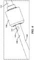
- FIG. 13shows a perspective view of yet another exemplary embodiment of the present disclosure
- FIG. 14shows a perspective view of another exemplary embodiment of the present disclosure
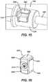
- FIG. 15shows a perspective view of yet another exemplary embodiment of the present disclosure
- FIG. 16shows a perspective view of a carrier and seal of the drive shaft assembly according to FIG. 15 ;
- FIG. 17shows a cross-sectional view of the carrier and seal of the drive shaft assembly of FIG. 15 ;
- FIG. 18shows a perspective view of a portion of the carrier of the drive shaft assembly of FIG. 15 .
- the present disclosuremay be further understood with reference to the following description and the appended drawings, wherein like elements are referred to with the same reference numerals.
- the present embodimentsrelate to the treatment of a bone and, in particular, relates the intramedullary reaming of a bone to remove bone material from the medullary canal of the bone. Material from the medullary canal may be removed to prepare the bone for an intramedullary implant and/or to collect material for bone grafting.
- Exemplary embodimentsdescribe a drive shaft assembly configured to be connected to a reamer device to drive or rotate a reamer head of the reamer device.
- the drive shaft assemblyincludes a drive shaft inserted into the reamer device and a seal coupleable to a portion of the drive shaft so that irrigation fluid supplied to the medullary canal via the reamer device is prevented from leaking therefrom as the assembled reamer device and drive shaft assembly are moved over a guide wire in the medullary canal.
- the sealis configured to be coupled to the drive shaft assembly to prevent the seal from being inadvertently disengaged from the drive shaft during use. Proper connection between the drive shaft and the seal prevents damage to the seal, reducing the likelihood of leakage.
- Aproximal@ and Adistal@are intended to refer to a direction toward (proximal) and away from (distal) a user of the device.
- a system 100comprises a reamer device 102 including a rotatable reamer head 104 sized and shaped to be inserted into a medullary canal of a long bone (e.g., femur) to ream and remove material from the medullary canal.
- the reamer device 102is configured to provide both irrigation and aspiration to the medullary canal while the medullary canal is being reamed to reduce heat generated by the reamer device 102 and to aid in the removal of material from the medullary canal.
- a drive shaft assembly 106is coupleable to the reamer device 102 and a driving tool (not shown) to drive (i.e., rotate) the reamer head 104 .
- the drive shaft assembly 106may be coupled to the reamer device 102 by inserting a drive shaft 108 of the drive shaft assembly 106 into the reamer device 102 to couple a distal end 110 of the drive shaft 108 to the reamer head 104 .
- a proximal end 112 of the drive shaft 108is then coupled to the driving tool, which rotates the drive shaft 108 to rotate the reamer head 104 .
- the assembled reamer device 102 and drive shaft assembly 106may then be inserted into the medullary canal by sliding the assembled reamer device 102 and drive shaft assembly 106 over a guide wire 170 positioned within the medullary canal.
- the drive shaft assembly 106includes a seal 114 that may be positioned along a portion of the drive shaft 108 .
- Current RIA systemsinclude a seal mounted over a proximal end of a drive shaft, which is connected to the driving tool.
- a proximal force of a guidewire on the seal and/or a continued longitudinal motion of the drive shaft over the guide wiredisengage the seal from the proximal end of the drive shaft allowing irrigation fluid to leak and/or increasing the risk that the seal may be left behind within the patient.
- the seal 114 of the drive shaft assembly 106is configured to be laterally inserted into a seal area 116 positioned along the drive shaft 108 .
- the reamer device 102includes a tubular member 118 extending from a proximal end 120 connected to a proximal housing 126 to a distal end 122 connectable to the reamer head 104 .
- the tubular member 118is sufficiently flexible to be inserted through a medullary canal of a bone despite a curvature of the bone.
- the distal end 122 of the tubular member 118is coupled to the reamer head 104 via a head connector 124 .
- the head connector 124allows the reamer head 104 to be rotatably coupled to the tubular member 118 .
- the reamer head 104is coupled to the tubular member 118 in a way that it permits the reamer head 104 to be rotated about a longitudinal axis of the reamer device 102 relative to the tubular member 118 and/or the head connector 124 .
- the reamer head 104includes a channel 105 extending therethrough and a plurality of blades 164 configured to ream the medullary canal as the reamer head 104 rotates relative to the flexible member 118 .
- an axis of the channel 106is substantially aligned with an axis of the lumen 138 .
- the reamer head 104further includes a plurality of openings through which irrigation fluid may be passed into the medullary canal during the reaming process.
- the head connector 124also includes a plurality of openings through which aspiration is achieved as would be understood by those skilled in the art.
- the reamer head 104may be releasably coupleable to the head connector 124 so that a reamer head 104 having a desired size suitable for the particular bone being treated may be selected from, for example, a plurality of heads 104 of different sizes.
- the proximal housing 126is connected to the proximal end of the tubular member 118 and includes an irrigation port 128 for connection to an irrigation fluid source, an aspiration port 130 for connection to an aspiration source and a drive shaft connector 132 at a proximal end 134 of the proximal housing 126 for connection to the drive shaft 108 .
- Each of the irrigation and aspiration ports 128 , 130is in communication with a corresponding lumen 138 of the tubular member 118 and may include features facilitating connection with tubes for connecting to irrigation/aspiration sources.
- the irrigation and aspiration ports 128 , 130may include barbs.
- the drive shaft connector 132includes a coupling feature for facilitating connection of the reamer device 102 and the drive shaft assembly 106 .
- the drive shaft assembly 106includes the drive shaft 108 and the seal 114 , which is laterally insertable into the seal area 116 .
- the drive shaft 108extends longitudinally from the proximal end 112 to a distal end 110 and includes a channel 154 extending therethrough.
- the drive shaft 108also includes a reamer connection portion 136 which may be configured as an increased diameter portion of the drive shaft 108 .
- the distal end 110 of the drive shaft 108includes a head engaging feature 142 for engaging a corresponding feature of the reamer head 104 .
- the head engaging feature 142includes a hex-shaped structure for engaging a correspondingly hexagonally shaped groove of the reamer head 104 .
- a length of a portion of the drive shaft 108 extending from the reamer connection portion 136 to the distal end 110is therefore selected to correspond to a distance from the reamer connector 132 to the reamer head 104 of the reamer device 102 .
- the reamer engagement feature 142 at the distal end 110 of the drive shaft 108must engage the corresponding engagement feature of the reamer head 104 .
- the proximal end 112 of the drive shaft 108may be similarly configured to be engaged to a driving tool such as, for example, a drill.
- the drive shaft 108also includes a lateral opening 160 extending laterally through a wall 162 thereof so that, when the drive shaft 108 is inserted into the reamer device 102 , the lateral opening 160 is aligned with the irrigation port 128 of the proximal housing 126 .
- irrigation fluid received through the irrigation portion 128is passed into the channel 154 of the drive shaft 108 via the lateral opening 160 so that irrigation fluid is supplied to the medullary canal via the openings of the reamer head 104 .
- the seal area 116may be configured as a hole extending laterally through the drive shaft 108 from a first wall opening 144 to a second wall opening 146 which, in this embodiment, substantially diametrically opposes the first wall opening 144 .
- the seal area 116is in communication with the channel 154 of the drive shaft 108 .
- Each of the first and second wall openings 144 , 146may include beveled or angled edges 148 along an exterior surface 150 of the drive shaft 108 for engaging a lip 152 of the seal 114 , as will be described in further detail below.
- the first and second wall openings 144 , 146include a groove or recess around a periphery thereof, along the exterior surface 150 .
- the seal areamay be positioned distally of the reamer connection portion 136 of the drive shaft 108 but proximally of the lateral opening 160 so that, when the drive shaft 108 is inserted into the reamer device 102 , the seal area 116 is covered by a portion of the reamer device 102 , preventing the seal 114 inserted therein, from being inadvertently disengaged therefrom.
- the seal 114is sized and shaped to be inserted into the seal area 116 so that the seal 114 extends across the channel 154 of the drive shaft 108 , covering the entire cross-sectional area of the channel 154 .
- the seal 114is sized and shaped so that, when the seal 114 is inserted into the seal area 116 , exterior surfaces 156 of the seal 114 are substantially flush with an exterior surface 150 of the drive shaft 108 .
- Exterior surfaces 156 of the seal 114may also include lips 158 (e.g., a larger cross-sectional area) for engaging the beveled edges 148 of the seal area 116 .
- the seal 114may have any of a variety of configurations so long as the seal 114 is insertable into the seal area 116 to seal the channel 154 .
- the seal 114may be configured as a bivalve formed of an elastomer and/or silicone material.
- the drive shaft assembly 106is assembled by inserting the seal 114 into the seal area 116 of the drive shaft 108 so that the lips 158 thereof engage the beveled edges 148 of the first and second openings 144 , 146 of the seal area 116 .
- the drive shaft 108is then inserted into the lumen 138 of the tubular member 118 of the reamer device 102 via the drive shaft connector 132 .
- the drive shaft 108may be inserted into the reamer device 102 until the reamer connection 136 engages or is configured to be engaged with the drive shaft connector 132 .
- the drive shaft connector 132 and the reamer connection portion 136may be coupled to one another in any of a variety of ways.
- a locking clip(not shown) is mounted over the reamer engagement portion 136 and the coupling feature of drive shaft connector 132 to lock the reamer engagement portion 136 and the drive shaft connector 132 relative to one another.
- An irrigation fluid source and an aspiration source(e.g., vacuum source) are also connected to the irrigation and aspiration ports 128 , 130 , respectively.
- the bonePrior to insertion of the reamer device 102 into the medullary canal, the bone is prepared by, for example, drilling an insertion opening into the bone and inserting the guide wire 170 into the medullary canal via the insertion opening.
- the reamer device 102(assembled with the drive shaft assembly 106 ) is then inserted into the medullary canal over the guide wire 170 so that the guide wire 170 is received within the channel 154 of the drive shaft 108 via the channel 105 of the reamer head 104 .
- the medullary canalis reamed while irrigation fluid is provided to the medullary canal via the irrigation port 128 .
- Irrigation fluidflows space through the channel 154 of the drive shaft 108 , around the guide wire 170 , and into the medullary canal via the openings of the reamer head 104 .
- Aspiration of tissue and/or fluidsmay be simultaneously provided through a space between an exterior surface 150 of the drive shaft 108 and interior of the tubular member 118 so that, for example, bone material for use in grafting may be suctioned therethrough via openings of the head connector 124 .
- a proximal end 172 of the guide wire 170is eventually pressed proximally into the seal 114 , piercing the seal 114 while also preventing irrigation fluid from flowing proximally past the seal 114 .
- the correspondingly sized and shapes seal 114 and seal area 116 along with a position of the seal area 116 distal of the reamer connection portion 136prevents from being inadvertently dislodged or disengaged from the seal area 116 , thereby reducing the likelihood of fluid leakage.
- the seal 114may simply be replaced with a new seal 114 so that the same drive shaft 108 may be reused for a second reaming process.
- a drive shaft assembly 206may be substantially similar to the drive shaft assembly 106 , and may be similarly utilized with the reamer device 102 described above with respect to the system 100 .
- a drive shaft assembly 206may include a seal 214 that is coupleable to a proximal end 212 of a drive shaft 208 via a carrier 280 formed of, for example, a hard, plastic material such as Acrylonitrile Butadiene Styrene (ABS).
- ABSAcrylonitrile Butadiene Styrene
- This carrier 280provides a stronger engagement with the proximal end 212 of the drive shaft 208 than a rubber or elastomer seal that is directly coupled to a proximal end of a drive shaft, as is available in current MA systems.
- the drive shaft 208may be substantially similar to the drive shaft 108 described above with respect to the system 100 . Rather than a seal area formed via lateral openings through the drive shaft, however, the proximal end 212 of the drive shaft 208 includes barbs 216 or other coupling features for engaging the carrier 280 .
- the carrier 280extends from a proximal end 282 to a distal end 284 and includes a channel 286 extending therethrough so that, when the carrier 280 is coupled to the drive shaft 208 , the channel 286 is substantially aligned with a channel of the drive shaft 208 .
- the channel 286includes a shoulder 288 therealong which prevents the seal 214 , which is received within the channel 286 , from being moved proximally therepast.
- a cross-sectional area of a proximal portion 290 of the channel 286 proximal of the shoulder 288is smaller than a cross-sectional are of a distal portion 292 of the channel 286 distal of the shoulder 288 .
- the distal portion 292is sized and shaped to receive the proximal end 212 of the drive shaft 208 therein so that the seal 214 is fixed between the shoulder 288 and the proximal end 212 of the drive shaft 208 .
- a diameter of the distal portion 292 of the channel 286may be smaller than a diameter of the proximal end 212 of the drive shaft 208 so that the carrier 280 is stretched thereover to engage the proximal end 212 .
- the carrier 280further includes a plurality of longitudinally extending perforations 294 extending from the distal end 284 toward the proximal end 282 along a portion of a length of the carrier 280 .
- Each of the longitudinally extending perforations 294extend substantially parallel to a longitudinal axis of the carrier 280 .
- the seal 214is sized and shaped to be received within the distal portion 292 of the channel 286 .
- the carrier 280is substantially tubular, having a substantially circular cross-section.
- the seal 214may be substantially disk-shaped. Pressing the seal 214 against the proximal end 212 of the drive shaft 208 via the carrier 280 during engagement thereof causes the seal 214 to expand over the barbs 216 of the proximal end 212 , sealing the channel of the drive shaft 208 .
- a drive shaft assembly 206 ′substantially similar to the drive shaft assembly 206 similarly comprises a seal 214 ′ engaged with a proximal end 212 ′ of a drive shaft 208 ′ via a carrier 280 ′.
- the carrier 280 ′ and the proximal end 212 ′include corresponding engaging features such as, for example, a circumferential notch 216 ′ about the proximal end 212 ′, which is sized and shaped to receive a correspondingly sized and shaped radially inwardly projecting tabs 298 ′ at the distal end 284 ′ of the carrier 280 ′.
- the carrier 280 ′in place of the plurality of longitudinally extending perforations 294 , the carrier 280 ′ includes a plurality of longitudinal slots 294 ′, which define distal arm segments 296 ′. These distal arm segments 296 ′ may be movable from a first biased configuration to a second radially outwardly deflected configuration as the carrier 280 ′ is pushed into a locked configuration along the proximal end 212 ′. Once the tabs 298 ′ are received within the notch 216 ′, the arm segments 296 ′ revert to their initial biased configuration, fixing the carrier 280 ′ to the proximal end 212 ′.
- a drive shaft assembly 306may be substantially similar to the drive shaft assemblies 206 , 206 ′.
- the drive shaft assembly 306comprises a seal 314 configured to be directly coupled to a proximal end 312 of a drive shaft 308 .
- the seal 314includes a distal portion 392 sized to be received within a channel 354 of the proximal end 312 and a proximal portion 390 formed of a soft polymer extending across a proximal opening 394 of the distal portion 392 .
- the proximal portion 390is configured to be pierced or broken via a guide wire passing therethrough, but is formed of material which may be compressed over the guide wired to prevent leaks thereabout.
- a drive shaft assembly 406may be substantially similar to the drive shaft assemblies 206 - 306 described above.
- the drive shaft assembly 406includes a carrier 480 for fixing an O-ring 414 , between a proximal end 412 of the shaft 408 and the carrier 480 .
- the carrier 480may be substantially similar to the carrier 280 described above with respect to the drive shaft assembly 206 .
- a channel 486extends from an opening at a distal end 484 of the carrier 480 to a closed proximal end 482 .
- the proximal end 482is configured to be broken via passage of a guide wire therethrough. Before the guide wire passes proximally through the proximal end 482 , however, the guide wire is inserted through the O-ring 414 which seals against an exterior surface of the guide wire to prevent passage of fluid thereabout.
- a drive shaft assembly 506may be substantially similar to the drive shaft assemblies described above.
- the drive shaft assembly 506similarly to the drive shaft assembles 206 - 406 described above, the drive shaft assembly 506 includes a carrier 580 for fixing a seal 514 to a drive shaft 508 .
- the carrier 580which includes the seal 514 mounted therein, however, is laterally inserted into a seal area 516 , substantially similarly to the drive shaft assembly 106 , as described above with respect to the system 100 .
- the drive shaft 508is substantially similar to the drive shaft 108 , including a seal area 516 defined via a hole extending laterally therethrough from a first wall opening 544 to a second wall opening (not shown).
- the seal area 516is open to and in communication with a channel of the drive shaft 508 .
- the seal area 516may extend through a reamer connecting portion 536 , which may be configured as an increased diameter portion of the drive shaft 508 .
- the seal area 516is sized and shaped to receive the carrier 580 therein.
- exterior edges 548e.g., edges of the seal area 516 along an exterior surface of the drive shaft 508 .
- exterior edges 548e.g., edges of the seal area 516 along an exterior surface of the drive shaft 508
- first and second openings 544may be beveled, angled and/or may include a groove extending about a periphery thereof for engaging biasing elements 558 of the carrier 580 .
- the carrier 580is sized and shaped to be received within the seal area 516 and houses the seal 514 therein so that, when the carrier 580 engages the seal area 516 , the seal 514 is aligned within the channel of the drive shaft 508 .
- the carrier 580may be sized and shaped so that, when the carrier 580 engages the seal area 516 , exterior surfaces 556 thereof extend substantially flush with an exterior surface 550 of the drive shaft 508 .
- the carrier 580may include a first set of biasing elements 558 proximate the exterior surfaces 556 of the carrier 580 so that the first set of biasing elements 558 are movable between a first configuration toward which they are biased and a second configuration in which the biasing elements 558 are deflected toward edges of the exterior surfaces 556 .
- the biasing elements 558are moved toward the second configuration.
- the first biasing elements 558are permitted to revert to the first configuration (under their natural bias) to engage the edges 548 of the first and second openings 544 .
- the seal 514may have any of a variety of configurations so long as the seal 514 is housed within the carrier 514 and extends across the channel of the drive shaft 508 , when the carrier 580 is inserted into the seal area 516 , to seal about a guide wire passed therethrough.
- the seal 514may be substantially similar to the seal 314 described above with respect to the drive shaft assembly 306 .
- a proximal end 590 of the seal 514may substantially align with the proximal end 582 of the carrier 580 .
- the carrier 580may further include a second biasing element 559 along a distal end 584 of the carrier 580 which, when the carrier 580 is received within the seal area 516 , biases the carrier 580 toward a proximal direction.
- the seal 514is further pressed against a proximal mating surface of the seal area 516 within the channel of the drive shaft 508 .
Landscapes
- Health & Medical Sciences (AREA)
- Surgery (AREA)
- Life Sciences & Earth Sciences (AREA)
- Engineering & Computer Science (AREA)
- Oral & Maxillofacial Surgery (AREA)
- Medical Informatics (AREA)
- Public Health (AREA)
- Nuclear Medicine, Radiotherapy & Molecular Imaging (AREA)
- Dentistry (AREA)
- Veterinary Medicine (AREA)
- Biomedical Technology (AREA)
- Heart & Thoracic Surgery (AREA)
- Orthopedic Medicine & Surgery (AREA)
- Molecular Biology (AREA)
- Animal Behavior & Ethology (AREA)
- General Health & Medical Sciences (AREA)
- General Engineering & Computer Science (AREA)
- Mechanical Engineering (AREA)
- Surgical Instruments (AREA)
Abstract
Description
Claims (20)
Priority Applications (8)
| Application Number | Priority Date | Filing Date | Title |
|---|---|---|---|
| US15/794,115US10646235B2 (en) | 2017-10-26 | 2017-10-26 | Guide wire seal for reamer irrigator aspirator system |
| JP2020523243AJP7322010B2 (en) | 2017-10-26 | 2018-10-26 | Guide wire sealing part of reamer irrigation aspiration system |
| AU2018354348AAU2018354348B2 (en) | 2017-10-26 | 2018-10-26 | Guide wire seal for reamer irrigator aspirator system |
| CA3078532ACA3078532A1 (en) | 2017-10-26 | 2018-10-26 | Guide wire seal for reamer irrigator aspirator system |
| CN201880069491.1ACN111278371B (en) | 2017-10-26 | 2018-10-26 | Guide wire seals for reamer irrigator aspirator systems |
| PCT/US2018/057624WO2019084352A2 (en) | 2017-10-26 | 2018-10-26 | Guide wire seal for reamer irrigator aspirator system |
| BR112020006558-7ABR112020006558A2 (en) | 2017-10-26 | 2018-10-26 | guide wire seal for aspiration milling system with irrigation |
| EP18801164.7AEP3700438B1 (en) | 2017-10-26 | 2018-10-26 | Guide wire seal for reamer irrigator aspirator system |
Applications Claiming Priority (1)
| Application Number | Priority Date | Filing Date | Title |
|---|---|---|---|
| US15/794,115US10646235B2 (en) | 2017-10-26 | 2017-10-26 | Guide wire seal for reamer irrigator aspirator system |
Publications (2)
| Publication Number | Publication Date |
|---|---|
| US20190125363A1 US20190125363A1 (en) | 2019-05-02 |
| US10646235B2true US10646235B2 (en) | 2020-05-12 |
Family
ID=64277853
Family Applications (1)
| Application Number | Title | Priority Date | Filing Date |
|---|---|---|---|
| US15/794,115Active2038-02-13US10646235B2 (en) | 2017-10-26 | 2017-10-26 | Guide wire seal for reamer irrigator aspirator system |
Country Status (8)
| Country | Link |
|---|---|
| US (1) | US10646235B2 (en) |
| EP (1) | EP3700438B1 (en) |
| JP (1) | JP7322010B2 (en) |
| CN (1) | CN111278371B (en) |
| AU (1) | AU2018354348B2 (en) |
| BR (1) | BR112020006558A2 (en) |
| CA (1) | CA3078532A1 (en) |
| WO (1) | WO2019084352A2 (en) |
Families Citing this family (2)
| Publication number | Priority date | Publication date | Assignee | Title |
|---|---|---|---|---|
| WO2019188918A1 (en)* | 2018-03-28 | 2019-10-03 | テルモ株式会社 | Medical device and usage for treatment |
| ES2949043B2 (en)* | 2022-02-21 | 2024-03-11 | Nela Biodynamics Sl | LONG BONE INTERNAL MILLING DEVICE |
Citations (39)
| Publication number | Priority date | Publication date | Assignee | Title |
|---|---|---|---|---|
| GB1458886A (en) | 1973-06-18 | 1976-12-15 | Kirschner H | Drilling or milling apparatus for the treatment of liv ing bone especially for dentistry |
| EP0420395A2 (en) | 1989-09-26 | 1991-04-03 | Interventional Technologies Inc | Seal for rotating torque tube with seal valve |
| US5403317A (en) | 1990-06-28 | 1995-04-04 | Bonutti; Peter M. | Apparatus and method for tissue removal |
| US5540707A (en) | 1992-11-13 | 1996-07-30 | Scimed Life Systems, Inc. | Expandable intravascular occlusion material removal devices and methods of use |
| US5695468A (en) | 1994-09-16 | 1997-12-09 | Scimed Life Systems, Inc. | Balloon catheter with improved pressure source |
| US6022354A (en) | 1998-12-04 | 2000-02-08 | Mercuri; Gregory M. | Bone harvesting collection and delivery system |
| US6024729A (en) | 1998-03-10 | 2000-02-15 | Vernay Laboratories, Inc. | Hemostasis valve assembly including guide wire seal |
| US6231543B1 (en) | 1999-04-15 | 2001-05-15 | Intella Interventional Systems, Inc. | Single lumen balloon catheter |
| US6332886B1 (en) | 1999-02-03 | 2001-12-25 | Synthes (Usa) | Surgical reamer and method of using same |
| US6387070B1 (en) | 1999-09-17 | 2002-05-14 | Nuvasive, Inc. | Bone slurry recovery |
| DE10130897C1 (en) | 2001-06-27 | 2003-01-09 | Bahner Feinwerktechnik Gmbh | Handpiece for a medical or cosmetic device comprises a clamping sleeve having a dirt-collecting chamber in a clamping sleeve section on the end of a collet chuck facing away from a tool insertion opening |
| US6565588B1 (en) | 2000-04-05 | 2003-05-20 | Pathway Medical Technologies, Inc. | Intralumenal material removal using an expandable cutting device |
| US6648854B1 (en) | 1999-05-14 | 2003-11-18 | Scimed Life Systems, Inc. | Single lumen balloon-tipped micro catheter with reinforced shaft |
| US6783533B2 (en) | 2001-11-21 | 2004-08-31 | Sythes Ag Chur | Attachable/detachable reaming head for surgical reamer |
| US20040230213A1 (en) | 2000-04-05 | 2004-11-18 | Pathway Medical Technologies, Inc. | Liquid seal assembly for a rotating torque tube |
| US20050156387A1 (en) | 2004-01-15 | 2005-07-21 | Medical Instrument Development Laboratories, Inc. | Vented seal having redundant sealing components |
| WO2005096952A1 (en) | 2004-04-05 | 2005-10-20 | Nippon Cable System Inc. | Method of collecting bone marrow and medical device for use therein |
| US7081123B2 (en) | 2002-06-18 | 2006-07-25 | Musculoskeletal Transplant Foundation | Bone marrow aspiration instrument |
| US20070021752A1 (en) | 2005-07-25 | 2007-01-25 | Rogers William G | Motorized surgical handpiece |
| US7198632B2 (en) | 2004-03-02 | 2007-04-03 | Boston Scientific Scimed, Inc. | Occlusion balloon catheter with longitudinally expandable balloon |
| US7204810B2 (en) | 2002-01-02 | 2007-04-17 | Sdgi Holdings, Inc. | Autogenous bone collection and delivery system |
| US7214059B2 (en) | 2001-03-06 | 2007-05-08 | Atsushi Takahashi | Bone collecting device |
| US20070276352A1 (en) | 2002-06-04 | 2007-11-29 | Stemcor Systems, Inc. | Removable device and method for tissue disruption |
| US7462181B2 (en) | 2002-06-04 | 2008-12-09 | Stanford Office Of Technology Licensing | Device and method for rapid aspiration and collection of body tissue from within an enclosed body space |
| US7497340B2 (en) | 2004-02-19 | 2009-03-03 | Stryker Corporation | Manifold and filter assembly with filter basket |
| US7771445B2 (en) | 1998-04-10 | 2010-08-10 | Ev3 Endovascular, Inc. | Rotational atherectomy system with stationary cutting elements |
| CN201701257U (en) | 2010-05-29 | 2011-01-12 | 张永强 | Chip cleaning bone drill for bone surgery |
| US8740908B2 (en) | 2010-11-02 | 2014-06-03 | Thompson Mis | Bone collection system |
| US8790349B2 (en) | 2005-03-15 | 2014-07-29 | Atsushi Takahashi | Autologous bone collection device having enhanced suction efficiency |
| US8790321B2 (en) | 2010-04-21 | 2014-07-29 | Genesis Medical Devices, LLC | Apparatus, system, and method for harvesting improved bone graft material with reamer-irrigator-aspirator (RIA) device |
| CN203898409U (en) | 2014-05-09 | 2014-10-29 | 山东恒一能源装备有限公司 | Skeletal fragment collector |
| US8920393B2 (en) | 2011-05-08 | 2014-12-30 | H & M Innovations, Llc | Autologous surgical bone collection and filtration |
| US9005163B2 (en) | 2010-08-03 | 2015-04-14 | Bayer Pharma Aktiengesellschaft | Balloon catheter with external delivery tube |
| US20150216539A1 (en) | 2014-02-06 | 2015-08-06 | Stryker European Holdings I, Llc | Bone marrow harvesting and storage |
| US20150359998A1 (en)* | 2013-01-15 | 2015-12-17 | A.V. Medical Technologies, Ltd. | Infusion catheter with guidewire valving |
| US20160278790A1 (en) | 2015-03-24 | 2016-09-29 | Stryker European Holdings I, Llc | Bone marrow harvesting device and storage methods |
| US20160325018A1 (en) | 2015-05-08 | 2016-11-10 | Fortus Medical, Inc. | Bone fragment and tissue processing system |
| WO2017023542A1 (en) | 2015-07-31 | 2017-02-09 | DePuy Synthes Products, Inc. | Method of preparing an osteogenic bone graft |
| US20170087349A1 (en) | 2011-02-28 | 2017-03-30 | Gmedix, Inc. | Hemostasis sealing device |
Family Cites Families (3)
| Publication number | Priority date | Publication date | Assignee | Title |
|---|---|---|---|---|
| US7951110B2 (en)* | 2008-11-10 | 2011-05-31 | Onset Medical Corporation | Expandable spinal sheath and method of use |
| CA2815186C (en)* | 2010-10-28 | 2015-12-29 | Covidien Lp | Material removal device and method of use |
| DK2941209T3 (en)* | 2013-01-07 | 2020-01-06 | Taryag Medical Ltd | Expandable atherectomy device |
- 2017
- 2017-10-26USUS15/794,115patent/US10646235B2/enactiveActive
- 2018
- 2018-10-26WOPCT/US2018/057624patent/WO2019084352A2/ennot_activeCeased
- 2018-10-26CACA3078532Apatent/CA3078532A1/enactivePending
- 2018-10-26AUAU2018354348Apatent/AU2018354348B2/enactiveActive
- 2018-10-26JPJP2020523243Apatent/JP7322010B2/enactiveActive
- 2018-10-26CNCN201880069491.1Apatent/CN111278371B/enactiveActive
- 2018-10-26BRBR112020006558-7Apatent/BR112020006558A2/ennot_activeIP Right Cessation
- 2018-10-26EPEP18801164.7Apatent/EP3700438B1/enactiveActive
Patent Citations (52)
| Publication number | Priority date | Publication date | Assignee | Title |
|---|---|---|---|---|
| GB1458886A (en) | 1973-06-18 | 1976-12-15 | Kirschner H | Drilling or milling apparatus for the treatment of liv ing bone especially for dentistry |
| EP0420395A2 (en) | 1989-09-26 | 1991-04-03 | Interventional Technologies Inc | Seal for rotating torque tube with seal valve |
| US6543455B2 (en) | 1990-06-28 | 2003-04-08 | Peter M. Bonutti | Cell harvesting method |
| US5403317A (en) | 1990-06-28 | 1995-04-04 | Bonutti; Peter M. | Apparatus and method for tissue removal |
| US5694951A (en) | 1990-06-28 | 1997-12-09 | Bonutti; Peter M. | Method for tissue removal and transplantation |
| US6174313B1 (en) | 1990-06-28 | 2001-01-16 | Peter M. Bonutti | Apparatus and method for tissue removal |
| US5540707A (en) | 1992-11-13 | 1996-07-30 | Scimed Life Systems, Inc. | Expandable intravascular occlusion material removal devices and methods of use |
| US5695468A (en) | 1994-09-16 | 1997-12-09 | Scimed Life Systems, Inc. | Balloon catheter with improved pressure source |
| US6024729A (en) | 1998-03-10 | 2000-02-15 | Vernay Laboratories, Inc. | Hemostasis valve assembly including guide wire seal |
| US7771445B2 (en) | 1998-04-10 | 2010-08-10 | Ev3 Endovascular, Inc. | Rotational atherectomy system with stationary cutting elements |
| US6022354A (en) | 1998-12-04 | 2000-02-08 | Mercuri; Gregory M. | Bone harvesting collection and delivery system |
| US6332886B1 (en) | 1999-02-03 | 2001-12-25 | Synthes (Usa) | Surgical reamer and method of using same |
| US6231543B1 (en) | 1999-04-15 | 2001-05-15 | Intella Interventional Systems, Inc. | Single lumen balloon catheter |
| US6648854B1 (en) | 1999-05-14 | 2003-11-18 | Scimed Life Systems, Inc. | Single lumen balloon-tipped micro catheter with reinforced shaft |
| US6387070B1 (en) | 1999-09-17 | 2002-05-14 | Nuvasive, Inc. | Bone slurry recovery |
| US6565588B1 (en) | 2000-04-05 | 2003-05-20 | Pathway Medical Technologies, Inc. | Intralumenal material removal using an expandable cutting device |
| US20040230213A1 (en) | 2000-04-05 | 2004-11-18 | Pathway Medical Technologies, Inc. | Liquid seal assembly for a rotating torque tube |
| US7214059B2 (en) | 2001-03-06 | 2007-05-08 | Atsushi Takahashi | Bone collecting device |
| DE10130897C1 (en) | 2001-06-27 | 2003-01-09 | Bahner Feinwerktechnik Gmbh | Handpiece for a medical or cosmetic device comprises a clamping sleeve having a dirt-collecting chamber in a clamping sleeve section on the end of a collet chuck facing away from a tool insertion opening |
| US6783533B2 (en) | 2001-11-21 | 2004-08-31 | Sythes Ag Chur | Attachable/detachable reaming head for surgical reamer |
| US8622953B2 (en) | 2002-01-02 | 2014-01-07 | Richard A. Hynes | Autogenous bone collection and delivery system |
| US7204810B2 (en) | 2002-01-02 | 2007-04-17 | Sdgi Holdings, Inc. | Autogenous bone collection and delivery system |
| US7462181B2 (en) | 2002-06-04 | 2008-12-09 | Stanford Office Of Technology Licensing | Device and method for rapid aspiration and collection of body tissue from within an enclosed body space |
| US8002733B2 (en) | 2002-06-04 | 2011-08-23 | Daniel Kraft | Device and method for rapid aspiration and collection of body tissue from within an enclosed body space |
| US20160000991A1 (en) | 2002-06-04 | 2016-01-07 | The Board Of Trustees Of The Leland Stanford Junior University | Device and method for rapid aspiration and collection of body tissue from within an enclosed body space |
| US20070276352A1 (en) | 2002-06-04 | 2007-11-29 | Stemcor Systems, Inc. | Removable device and method for tissue disruption |
| US9131925B2 (en) | 2002-06-04 | 2015-09-15 | The Board Of Trustees Of The Leland Stanford Junior University | Device and method for rapid aspiration and collection of body tissue from within an enclosed body space |
| US8109919B2 (en) | 2002-06-04 | 2012-02-07 | Daniel Kraft | Device and method for rapid aspiration and collection of body tissue from within an enclosed body space |
| US8043253B2 (en) | 2002-06-04 | 2011-10-25 | Daniel Kraft | Device and method for rapid aspiration and collection of body tissue from within an enclosed body space |
| US7081123B2 (en) | 2002-06-18 | 2006-07-25 | Musculoskeletal Transplant Foundation | Bone marrow aspiration instrument |
| US20050156387A1 (en) | 2004-01-15 | 2005-07-21 | Medical Instrument Development Laboratories, Inc. | Vented seal having redundant sealing components |
| US8088291B2 (en) | 2004-02-19 | 2012-01-03 | Stryker Corporation | Method of collecting medical waste in a waste collection unit using disposable manifold with staged waste filtering/processing |
| US7497340B2 (en) | 2004-02-19 | 2009-03-03 | Stryker Corporation | Manifold and filter assembly with filter basket |
| US7198632B2 (en) | 2004-03-02 | 2007-04-03 | Boston Scientific Scimed, Inc. | Occlusion balloon catheter with longitudinally expandable balloon |
| WO2005096952A1 (en) | 2004-04-05 | 2005-10-20 | Nippon Cable System Inc. | Method of collecting bone marrow and medical device for use therein |
| US20090187116A1 (en) | 2004-04-05 | 2009-07-23 | Yasuharu Noishiki | Method for harvesting bone marrow and its medical apparatus |
| US8790349B2 (en) | 2005-03-15 | 2014-07-29 | Atsushi Takahashi | Autologous bone collection device having enhanced suction efficiency |
| US20070021752A1 (en) | 2005-07-25 | 2007-01-25 | Rogers William G | Motorized surgical handpiece |
| US20170112978A1 (en) | 2010-04-21 | 2017-04-27 | Genesis Medical Devices, LLC | Removable biocompatible substrate filter for a reaming and collection device |
| US8790321B2 (en) | 2010-04-21 | 2014-07-29 | Genesis Medical Devices, LLC | Apparatus, system, and method for harvesting improved bone graft material with reamer-irrigator-aspirator (RIA) device |
| US9555169B2 (en) | 2010-04-21 | 2017-01-31 | Genesis Medical Devices, LLC | Apparatus for harvesting improved bone graft material utilizing an implantable biodegradable filter |
| CN201701257U (en) | 2010-05-29 | 2011-01-12 | 张永强 | Chip cleaning bone drill for bone surgery |
| US9005163B2 (en) | 2010-08-03 | 2015-04-14 | Bayer Pharma Aktiengesellschaft | Balloon catheter with external delivery tube |
| US8740908B2 (en) | 2010-11-02 | 2014-06-03 | Thompson Mis | Bone collection system |
| US20170087349A1 (en) | 2011-02-28 | 2017-03-30 | Gmedix, Inc. | Hemostasis sealing device |
| US8920393B2 (en) | 2011-05-08 | 2014-12-30 | H & M Innovations, Llc | Autologous surgical bone collection and filtration |
| US20150359998A1 (en)* | 2013-01-15 | 2015-12-17 | A.V. Medical Technologies, Ltd. | Infusion catheter with guidewire valving |
| US20150216539A1 (en) | 2014-02-06 | 2015-08-06 | Stryker European Holdings I, Llc | Bone marrow harvesting and storage |
| CN203898409U (en) | 2014-05-09 | 2014-10-29 | 山东恒一能源装备有限公司 | Skeletal fragment collector |
| US20160278790A1 (en) | 2015-03-24 | 2016-09-29 | Stryker European Holdings I, Llc | Bone marrow harvesting device and storage methods |
| US20160325018A1 (en) | 2015-05-08 | 2016-11-10 | Fortus Medical, Inc. | Bone fragment and tissue processing system |
| WO2017023542A1 (en) | 2015-07-31 | 2017-02-09 | DePuy Synthes Products, Inc. | Method of preparing an osteogenic bone graft |
Non-Patent Citations (2)
| Title |
|---|
| International Search Report and Written Opinion (PCT/US2018/057624) dated Jul. 15, 2019, 10 pages. |
| Written Opinion (PCT/US2018/057624) dated Jul. 23, 2019, 14 pages. |
Also Published As
| Publication number | Publication date |
|---|---|
| AU2018354348A1 (en) | 2020-03-19 |
| JP7322010B2 (en) | 2023-08-07 |
| WO2019084352A3 (en) | 2019-08-15 |
| CN111278371B (en) | 2024-01-30 |
| AU2018354348B2 (en) | 2024-10-24 |
| WO2019084352A2 (en) | 2019-05-02 |
| JP2021500952A (en) | 2021-01-14 |
| EP3700438B1 (en) | 2024-06-05 |
| CA3078532A1 (en) | 2019-05-02 |
| EP3700438A2 (en) | 2020-09-02 |
| CN111278371A (en) | 2020-06-12 |
| BR112020006558A2 (en) | 2020-10-13 |
| US20190125363A1 (en) | 2019-05-02 |
Similar Documents
| Publication | Publication Date | Title |
|---|---|---|
| US12121262B2 (en) | Arthroscopic flexible portal cannula device and delivery system | |
| JP6735787B2 (en) | Sheath assembly for inserting a cord-shaped element, in particular a catheter, into the body of a patient | |
| JP5480484B2 (en) | Bladeless obturator for use in a surgical trocar assembly | |
| US8926508B2 (en) | Access assembly with dual anchor and seal capabilities | |
| US20070282268A1 (en) | Thoracentesis catheter system with self-sealing valve | |
| EP3010431B1 (en) | Transapical introducer | |
| US11701137B2 (en) | Reusable blade hub assembly | |
| CN103079483A (en) | Powered surgical tissue cutting instrument having an irrigation system | |
| AU2018354348B2 (en) | Guide wire seal for reamer irrigator aspirator system | |
| MX2013011273A (en) | Medical device with interference members to prevent re -use. | |
| US20230105857A1 (en) | Obturator for cannula with internal features | |
| HK40035024B (en) | Guide wire seal for reamer irrigator aspirator system | |
| HK40035024A (en) | Guide wire seal for reamer irrigator aspirator system | |
| US7632254B1 (en) | Device for splitting the tubular body of a catheter or sheath | |
| HK40021315A (en) | Guide wire seal for reamer irrigator aspirator system | |
| US20120004644A1 (en) | Pleural drainage system locking dilator | |
| US12082841B2 (en) | Declogging method and system | |
| CN111479526A (en) | Thin cannula trocar and method | |
| US20200205853A1 (en) | Arthroscopic Cannula with Removable Fluid Seal System | |
| KR102070904B1 (en) | Trocar for chest |
Legal Events
| Date | Code | Title | Description |
|---|---|---|---|
| FEPP | Fee payment procedure | Free format text:ENTITY STATUS SET TO UNDISCOUNTED (ORIGINAL EVENT CODE: BIG.); ENTITY STATUS OF PATENT OWNER: LARGE ENTITY | |
| STPP | Information on status: patent application and granting procedure in general | Free format text:DOCKETED NEW CASE - READY FOR EXAMINATION | |
| AS | Assignment | Owner name:MEDICAL DEVICE BUSINESS SERVICES, INC., INDIANA Free format text:ASSIGNMENT OF ASSIGNORS INTEREST;ASSIGNOR:MOSES, TIMOTHY P.;REEL/FRAME:045447/0756 Effective date:20171027 Owner name:SYNTHES USA PRODUCTS, LLC, PENNSYLVANIA Free format text:ASSIGNMENT OF ASSIGNORS INTEREST;ASSIGNORS:KIERSH, JEFF;SHANE, CHRISTOPHER;KERR, SEAN;SIGNING DATES FROM 20171102 TO 20171113;REEL/FRAME:045447/0630 Owner name:DEPUY SYNTHES PRODUCTS, INC., MASSACHUSETTS Free format text:ASSIGNMENT OF ASSIGNORS INTEREST;ASSIGNORS:MEDICAL DEVICE BUSINESS SERVICES, INC.;SYNTHES USA PRODUCTS, LLC;REEL/FRAME:045447/0831 Effective date:20180122 | |
| STPP | Information on status: patent application and granting procedure in general | Free format text:NON FINAL ACTION MAILED | |
| STPP | Information on status: patent application and granting procedure in general | Free format text:NOTICE OF ALLOWANCE MAILED -- APPLICATION RECEIVED IN OFFICE OF PUBLICATIONS | |
| STPP | Information on status: patent application and granting procedure in general | Free format text:NOTICE OF ALLOWANCE MAILED -- APPLICATION RECEIVED IN OFFICE OF PUBLICATIONS | |
| STPP | Information on status: patent application and granting procedure in general | Free format text:DOCKETED NEW CASE - READY FOR EXAMINATION | |
| STPP | Information on status: patent application and granting procedure in general | Free format text:NOTICE OF ALLOWANCE MAILED -- APPLICATION RECEIVED IN OFFICE OF PUBLICATIONS | |
| STCF | Information on status: patent grant | Free format text:PATENTED CASE | |
| MAFP | Maintenance fee payment | Free format text:PAYMENT OF MAINTENANCE FEE, 4TH YEAR, LARGE ENTITY (ORIGINAL EVENT CODE: M1551); ENTITY STATUS OF PATENT OWNER: LARGE ENTITY Year of fee payment:4 |