US10644761B2 - Distributed antenna system for MIMO communications - Google Patents
Distributed antenna system for MIMO communicationsDownload PDFInfo
- Publication number
- US10644761B2 US10644761B2US15/707,826US201715707826AUS10644761B2US 10644761 B2US10644761 B2US 10644761B2US 201715707826 AUS201715707826 AUS 201715707826AUS 10644761 B2US10644761 B2US 10644761B2
- Authority
- US
- United States
- Prior art keywords
- simulated
- mimo
- location
- mimo signal
- environment
- Prior art date
- Legal status (The legal status is an assumption and is not a legal conclusion. Google has not performed a legal analysis and makes no representation as to the accuracy of the status listed.)
- Active
Links
Images


Classifications
- H—ELECTRICITY
- H04—ELECTRIC COMMUNICATION TECHNIQUE
- H04B—TRANSMISSION
- H04B7/00—Radio transmission systems, i.e. using radiation field
- H04B7/02—Diversity systems; Multi-antenna system, i.e. transmission or reception using multiple antennas
- H04B7/04—Diversity systems; Multi-antenna system, i.e. transmission or reception using multiple antennas using two or more spaced independent antennas
- H04B7/0413—MIMO systems
- H—ELECTRICITY
- H04—ELECTRIC COMMUNICATION TECHNIQUE
- H04B—TRANSMISSION
- H04B17/00—Monitoring; Testing
- H04B17/30—Monitoring; Testing of propagation channels
- H04B17/309—Measuring or estimating channel quality parameters
- H—ELECTRICITY
- H04—ELECTRIC COMMUNICATION TECHNIQUE
- H04B—TRANSMISSION
- H04B7/00—Radio transmission systems, i.e. using radiation field
- H04B7/02—Diversity systems; Multi-antenna system, i.e. transmission or reception using multiple antennas
- H04B7/022—Site diversity; Macro-diversity
- H—ELECTRICITY
- H04—ELECTRIC COMMUNICATION TECHNIQUE
- H04B—TRANSMISSION
- H04B7/00—Radio transmission systems, i.e. using radiation field
- H04B7/02—Diversity systems; Multi-antenna system, i.e. transmission or reception using multiple antennas
- H04B7/022—Site diversity; Macro-diversity
- H04B7/026—Co-operative diversity, e.g. using fixed or mobile stations as relays
- H—ELECTRICITY
- H04—ELECTRIC COMMUNICATION TECHNIQUE
- H04B—TRANSMISSION
- H04B7/00—Radio transmission systems, i.e. using radiation field
- H04B7/02—Diversity systems; Multi-antenna system, i.e. transmission or reception using multiple antennas
- H04B7/04—Diversity systems; Multi-antenna system, i.e. transmission or reception using multiple antennas using two or more spaced independent antennas
- H04B7/06—Diversity systems; Multi-antenna system, i.e. transmission or reception using multiple antennas using two or more spaced independent antennas at the transmitting station
- H04B7/0686—Hybrid systems, i.e. switching and simultaneous transmission
- H04B7/0691—Hybrid systems, i.e. switching and simultaneous transmission using subgroups of transmit antennas
- H—ELECTRICITY
- H04—ELECTRIC COMMUNICATION TECHNIQUE
- H04B—TRANSMISSION
- H04B7/00—Radio transmission systems, i.e. using radiation field
- H04B7/02—Diversity systems; Multi-antenna system, i.e. transmission or reception using multiple antennas
- H04B7/04—Diversity systems; Multi-antenna system, i.e. transmission or reception using multiple antennas using two or more spaced independent antennas
- H04B7/0413—MIMO systems
- H04B7/0426—Power distribution
- H—ELECTRICITY
- H04—ELECTRIC COMMUNICATION TECHNIQUE
- H04B—TRANSMISSION
- H04B7/00—Radio transmission systems, i.e. using radiation field
- H04B7/02—Diversity systems; Multi-antenna system, i.e. transmission or reception using multiple antennas
- H04B7/04—Diversity systems; Multi-antenna system, i.e. transmission or reception using multiple antennas using two or more spaced independent antennas
- H04B7/0413—MIMO systems
- H04B7/0452—Multi-user MIMO systems
- H—ELECTRICITY
- H04—ELECTRIC COMMUNICATION TECHNIQUE
- H04B—TRANSMISSION
- H04B7/00—Radio transmission systems, i.e. using radiation field
- H04B7/02—Diversity systems; Multi-antenna system, i.e. transmission or reception using multiple antennas
- H04B7/10—Polarisation diversity; Directional diversity
Definitions
- Embodiments of the inventionare directed to wireless communication systems, and specifically directed to a distributed antenna system for wireless MIMO communications.
- a contemporary wireless communication systemsuch as distributed antenna system, includes a plurality of remote units distributed throughout a service area (e.g., a building) to provide coverage within the service area of the system.
- each remote antenna unitis typically coupled to a master unit, which, in turn, is coupled to at least one single-input- and single-output (“SISO”) base transceiver station (“BTS,” or more simply, “base station”).
- SISOsingle-input- and single-output
- BTSbase transceiver station
- Each remote unitgenerally transceives wireless signals with a number of wireless devices, such as a telephone devices or computing devices in the proximity of the remote unit.
- the wireless signals from each remote unitare associated with one or more BTSs.
- the wireless devicesmay communicate with the system BTS's through any of the wireless signals from the remote units.
- MIMOMultiple-Input/Multiple-Output
- MIMO systemshave capabilities that allow them to fully exploit the multi-path richness of a wireless channel. This is in contrast with traditional techniques that try to counteract multi-path effects rather than embrace them.
- MIMO systemsgenerally rely upon multi-element antennas at both of the ends of the communication links, such as at the base station and also in the mobile device.
- MIMO systemsalso may provide multiplexing gain, which allows multi data streams to be transmitted over spatially-independent parallel sub-channels. This may lead to a significant increase either in the system capacity or in the data throughput to each wireless device.
- distributed antenna systemscannot take advantage of MIMO technology because they are just designed to provide SISO wireless coverage.
- a wireless devicecommunicates with only one of the remote units, the signals of which are typically isolated from signals of other remote units using base station sectorization techniques. In this manner, the signals from different remote units avoid interference due to overlap of coverage areas.
- the wireless signals from each remote unitare typically at the same frequency and carry the same data.
- Additional problemsoccur with a distributed antenna system disposed within an indoor environment.
- indoor environmentsare often associated with increased amounts of multipath richness.
- internal building componentse.g., columns, pipes, walls, doors
- objects inside that buildinge.g., computers, desks, fixtures
- SISO distributed antenna systemsare typically designed to provide wireless coverage within a particular indoor environment.
- antenna shadowingcan occur depending upon the particular layout, user position, and obstacles within that indoor environment.
- Embodiments of the inventionprovide a method of deploying a distributed antenna system.
- the methodcomprises outputting at least a first signal and a second signal from a multiple-input and multiple-output (MIMO) base station and coupling first and second master units to the MIMO base station, the first and second master units configured to receive the first and second signal, respectively.
- the methodfurther comprises coupling a first remote unit to the first master unit, the first remote unit communicating the first signal a first air interface located within an environment at a first location and coupling a second remote unit to the second master unit, the second remote unit communicating the second signal over a second air interface within the environment at a second location.
- the methodthen comprises analyzing at least an imbalance of received power between the first and second signals determined within the environment at a third location to determine whether a predetermined capacity for MIMO communications with the system has been achieved.
- Alternative embodiments of the inventionalso provide a method for determining the placement of a plurality of antennas of a distributed antenna system with a computing system of the type that includes one or more processors and a memory.
- the methodcomprises simulating a first remote unit communicating a first signal over a first air interface located within an environment at a first location and simulating a second remote unit communicating a second signal over a second interface located within an environment at a second location.
- the methodfurther comprises analyzing at least a simulated imbalance of received power between the first and second signals determined within the environment at a third location to determine whether a predetermined capacity for MIMO communications with the system has been achieved.
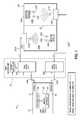
- FIG. 1is a block diagram of a distributed antenna system consistent with embodiments of the invention.
- FIG. 2is a detailed block diagram of a master unit utilized in embodiments of the invention.
- FIGS. 3A and 3Bare a detailed block diagram of a portion of a remote unit utilized in embodiments of the invention.
- FIG. 4is a detailed block diagram of an alternate portion of a remote unit utilized in embodiments of the invention.
- FIG. 5is a data plot illustrating the channel capacity increase as a function of SNIR, and that further illustrates that, for a given environment, the optimization of MIMO channel capacity depends upon the optimization of the SNIR and the CCN consistent with embodiments of the invention.
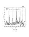
- FIG. 6is a data plot illustrating the typical CCN distribution in a “dense” indoor environment with co-polarized antennas consistent with embodiments of the invention.
- FIG. 7is a data plot illustrating the typical CCN distribution in an “open” indoor environment with co-polarized antennas consistent with embodiments of the invention.
- FIG. 8is a data plot illustrating the typical CCN distribution in a “large” indoor environment with co-polarized antennas consistent with embodiments of the invention.
- FIG. 9is an illustration of an indoor environment in which four remote units have been distributed and in which various imbalances between two signals of a 2 ⁇ 2 MIMO scheme have been determined consistent with embodiments of the invention.
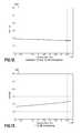
- FIG. 10is a data plot illustrating the effect of an imbalance of the received power of two signals on the CCN when that imbalance is from about 5 dB to about 10 dB.
- FIG. 11is a data plot illustrating the effect of an imbalance of the received power of two signals on the CCN when that imbalance is from about 5 dB to about 10 dB.
- FIG. 12is a data plot illustrating the effect of an imbalance of the received power of two signals on the CCN when that imbalance is from about 10 dB to about 15 dB.
- FIG. 13is a data plot illustrating the effect of an imbalance of the received power of two signals on the CCN when that imbalance is greater than about 15 dB.
- FIG. 14is a data plot illustrating the effect of the CCN and SNIR on the capacity of a MIMO system consistent with embodiments of the invention.
- FIG. 15is a flowchart illustrating a sequence of operations to selectively determine a location to deploy a plurality of remote units, or a plurality of antennas of remote units, to optimize the capacity of a MIMO DAS in an environment consistent with embodiments of the invention.
- FIG. 16is a flowchart illustrating a sequence of operations for a user to selectively tune the operation of a MIMO DAS in either a SU-MIMO mode of operation or a MU-MIMO mode of operation based upon a power imbalance consistent with embodiments of the invention.
- FIG. 17is a diagrammatic illustration of a MIMO DAS that includes co-located remote antennas within an indoor environment consistent with embodiments of the invention.
- FIG. 18is a diagrammatic illustration of the MIMO DAS of FIG. 17 in which the remote antennas have been located in different areas of the indoor environment and have overlapping coverage.
- FIG. 19is a diagrammatic illustration of the MIMO DAS of FIG. 17 in which the remote antennas have been located in different areas of the indoor environment and do not have overlapping coverage.
- FIG. 1illustrates a schematic view of one possible implementation of a Multiple-Input/Multiple-Output (“MIMO”) distributed antenna system 10 , wherein a MIMO base station (“BTS”) 12 is incorporated in or proximate to an environment in accordance with the invention.
- MIMOMultiple-Input/Multiple-Output
- the system 10includes a MIMO BTS 12 that might be configured with at least two antennas 14 and 16 . While a 2 ⁇ 2 MIMO BTS is illustrated, one of skill in the art would understand that additional antennas might be used for a different MIMO scheme.
- the first antenna 14is coupled to a first master unit 18 a through a first signal link 20 a
- the second antenna 16is coupled to a second master unit 18 b through a second signal link 20 b
- the MIMO BTS 12might not be configured with antennas.
- the MIMO BTS 12includes at least two antenna ports (not shown) in place of the antennas 14 and 16 .
- the antennas 15 and 16may be implemented elsewhere to capture the MIMO signals from another BTS to forward to the MIMO BTS 12 .
- a first antenna portis coupled to the first master unit 18 a through the first signal link 20 a
- a second antenna portis coupled to the second master unit 18 b through the second signal link 20 b .
- the signal linksare any appropriate form for passing signals between the components.
- the first and second master units 18 a - bmight be configured as first and second sub-master units 18 a - b of a MIMO master unit 19 .
- the master units 18 a - bare coupled through respective broad band transport mediums or links 22 a - b to a plurality of respective remote units 24 a - b .
- Each link 22 a - bmight be a high-speed digital link or a wideband analogue signal transmission link.
- an analog transport medium/linkmay be used for connecting the remote units 24 a - b with respective master units 18 a - b .
- the transport linksmay be implemented as optical links using optical fiber as discussed below. With such fiber, the traffic between the remote units 24 a - b and the master units 18 a - b may be implemented using a radio-over-fiber (“RoF”) format, for example.
- RoFradio-over-fiber
- each of the links 22 a - bmay be a wideband digitally modulated optical interface, such as fiber optic cable.
- each master unit 18 a - bmay be configured to digitize their respective input signals and output those digital signals for their respective remote units 24 a - b .
- the remote units 24 a - bmay be configured to receive the digital output signals from their respective master units 18 a - b , convert the digital output signals into electrical signals, if necessary, de-frame various time slots and/or de-serialize the electrical signals, and transmit the electrical signals via respective local antennas 25 a - b .
- the master units 18 a - b and remote units 22 a - bmay be controlled by a system controller 27 , which may provide overall supervision and control of the master units 18 a - b and remote units 22 a - b , as well as alarm forwarding.
- FIG. 1illustrates that the remote units 24 a - b , or at least the respective antennas 25 a - b for the remote units 24 a - b , are disposed within an indoor environment 26 .
- an indoor environment 26includes structures that can cause obstruction (partial or total) of the radio transmissions. These include walls, partitions, structural components, electrical conduits, plumbing, doors, computers, and people, for example.
- the indoor environment 26is illustrated for discussion purposes as including two areas 28 a - b that are provided with signals by the respective remote units 24 a - b and that may be at least somewhat electromagnetically isolated.
- the areas 28 a - bare illustrated as separated by an illustrative separator 30 , such as at least one partition or wall 30 , though one having ordinary skill in the art will appreciate that the areas 28 a - b may be at least somewhat electromagnetically isolated by way of other structures within the indoor environment 26 , by the distance between the two areas 28 a - b , or in some other manner as will be appreciated by one having ordinary skill in the art.
- environment 26might include other areas in addition to 28 a - b that affect the signals of other remote units of the plurality in addition to the remote unites 24 a - b that are illustrated for discussion purposes.
- remote units 24 a - bcan provide signals to wireless device 32 a in its respective area 28 a , but there is a power imbalance between the signals received by device 32 a from the respective remote units 24 a - b .
- remote units 24 a - bcan provide signals to wireless device 32 b in its respective area 28 b , but there is a power imbalance between the signals received by device 32 b from the respective remote units 24 a - b .
- Each wireless device 32 a - bmay be configured with at least two antennas 34 a - d to communicate signals to and/or from the remote units 24 a - b according to MIMO schemes. As illustrated in FIG. 1 , a first wireless device 32 a is configured with at least two antennas 34 a - b , while a second wireless device 32 b is configured with at least two antennas 34 c - d.
- the remote units 24 a - bare configured to send and/or receive digital RF voice and/or data signals to and/or from the wireless devices 32 a - b via their local antennas 25 a - b .
- the master units 18 a - bconvert a signal from their respective remote units 24 a - b from an optical signal to an electrical signal and send the electrical signal to the antennas 14 and/or 16 of the MIMO BTS 12 , which may be configured to detect and receive their respective portions thereof.
- the master units 18 a - bmay convert a signal from their respective remote units 24 a - b from an optical signal to an analog electrical signal, separate the electrical signal into a plurality of electrical signals in a plurality of bands corresponding to those utilized by the MIMO BTS 12 , convert the plurality of electrical signals into a plurality of analog signals, and send the plurality of analog signals to the MIMO BTS 12 .
- a master unit 18 a - bmay be selectively connected to respective remote units 24 a - b in a number of ways.
- master unit 18 ais illustrated as connected to remote unit 24 a through full-duplex link 22 a (e.g., a time-division multiplexed link) for uplink and downlink to and from the remote unit 24 a .
- Master unit 18 bis connected to remote unit 24 b in a similar manner.
- the master units 18 a - bmay be connected through two half-duplex links to each respective remote unit 24 a - b .
- the master unit 18 acan be connected through a first half-duplex link (not shown) to remote unit 24 a for uplink to the remote unit 24 a , and be connected through a second half-duplex link (not shown) to remote unit 24 a for downlink from the remote unit 24 a .
- Master unit 18 bmay be similarly connected to remote unit 24 b .
- the uplink signals and downlink signalsare carried on different wavelengths and a wavelength division multiplexer (“WDM”) is employed to combine and/or split the two optical signals at the master units 18 a - b and remote units 24 a - b .
- WDMwavelength division multiplexer
- the master units 18 a - b and remote units 24 a - bmay communicate through a different analog or digital transceiver for high data rate media such as coax cable, twisted pair copper wires, free space RF or optics, or shared networks such as Ethernet, SONET, SDH, ATM and/or PDH, among others, including one that exploits WDM.
- high data rate mediasuch as coax cable, twisted pair copper wires, free space RF or optics, or shared networks such as Ethernet, SONET, SDH, ATM and/or PDH, among others, including one that exploits WDM.
- portions of the system 10might be coupled to a SISO BTS. Accordingly, embodiments of the invention may be used to retrofit such SISO distributed antenna systems, allowing substantial costs savings using existing SISO equipment to implement MIMO distributed antenna systems to implement MIMO modes of operation in accordance with the aspects of the invention.
- a systemmight include two SISO BTSs that can be replaced with one MIMO BTS 12 consistent with embodiments of the invention.
- the signals provided by the respective remote units 24 a - b to the mobile devices 32 a - b in the environment 26may be associated with a power imbalance or be at least somewhat electromagnetically isolated.
- the system 10in the areas where the signals from the respective remote units 24 a - b are isolated, the system 10 is configured to utilize multi-user (“MU”) MIMO techniques to communicate with the wireless devices 32 a - b in those isolated areas.
- MUmulti-user
- the system 10is configured to utilize single-user (“SU”) MIMO techniques to communicate with the wireless devices 32 a - b in those overlapping areas.
- the system 10is configured to dynamically switch between SU-MIMO modes of operation and MU-MIMO modes of operation for sending signals to the wireless devices 32 a - b based upon signal quality indicators provided by those wireless devices 32 a - b .
- 3GPP LTE MIMO featuressuch as TX diversity, DL SU-MIMO, as well as DL/UL MU-MIMO may be dynamically used.
- each remote unit 24 a - bprovides signals to, and receives signals from, respective wireless devices 32 a - b present within the respective areas 28 a - b .
- uplink collaborative MIMOfor WiMAX
- uplink MU-MIMOfor LTE
- each of the wireless devices 32 a - bmay share resources (e.g., DL/UL MU-MIMO resources) as well as be associated with a high sector capacity (e.g., again, DL/UL MU-MIMO).
- the MIMO BTS 12is configured with at least one central processing unit (“CPU”) 36 coupled to a memory 38 .
- CPU 36is typically implemented in hardware using circuit logic disposed on one or more physical integrated circuit devices or chips.
- Each CPU 36may be one or more microprocessors, micro-controllers, field programmable gate arrays, or ASICs, while memory 38 may include random access memory (RAM), dynamic random access memory (DRAM), static random access memory (SRAM), flash memory, and/or another digital storage medium, and also typically implemented using circuit logic disposed on one or more physical integrated circuit devices, or chips.
- RAMrandom access memory
- DRAMdynamic random access memory
- SRAMstatic random access memory
- flash memoryand/or another digital storage medium
- memory 38may be considered to include memory storage physically located elsewhere in the MIMO BTS 12 , e.g., any cache memory in the at least one CPU 36 .
- Memory 38includes a scheduler 40 that can be executed by the CPU 36 to dynamically switch the operation of the system 10 from a SU-
- the wireless device 32may provide feedback to the MIMO BTS 12 about the signals to and/or from that wireless device 32 .
- the uplink feedback provided by the wireless device 32 for support of downlink signals from the MIMO BTS 12can include one or more performance metrics related to that signal, including a Rank Indicator (RI), a Pre-coding Matrix Indicator (PMI), and a Channel Quality Indicator (CQI).
- RIindicates the number of layers (data streams), which can be supported by the spatial channel experienced at the wireless device 32 .
- the PMIis then calculated conditioned on the associated RI, and the CQI is calculated conditioned on the associated RI and PMI.
- a high value CQIis indicative of a channel of high quality.
- For an RI1, only one CQI is reported for each reporting unit in frequency because in such a condition only one layer (data stream) can be transmitted by the MIMO BTS 12 .
- On the other hand for RI2, two CQI are reported for the spatial multiplexing (DL SU-MIMO) as different data streams experience different spatial channels.
- the PMIindicates the preferred pre-coding candidate for the corresponding frequency unit and is selected from the possible pre-coding candidates of Table 1 for the case of two transmitting antennas according to the RI.
- the CQImight represent a measure of Signal to Interference plus Noise Ratio (SINR), but in fact it is coded in terms of the Modulation and Coding Scheme (MCS) required for a particular error rate probability, as highlighted in Table 2.
- SINRSignal to Interference plus Noise Ratio
- MCSModulation and Coding Scheme
- the CQIindicates the combination of the maximum information data size and the modulation scheme among QPSK, 16QAM, and 64QAM, which can provide block error rate not exceeding 0.1 (i.e. 10 ⁇ 1 ) assuming that the reported rank and the reported pre-coding matrix are applied in the time-frequency resource.
- the user equipment or mobile devicecan report the maximum data size that it can receive and demodulate, taking into account its receiver ability.
- the scheduler 40 of the MIMO BTS 12is configured to adapt the downlink transmission mode in order to accommodate the data reception of a wireless device 32 .
- the scheduler 40might chose either the DL SU-MIMO or the DL MU-MIMO modes of operation for one or more wireless devices 32 .
- the scheduler's 40 selection among these two MIMO schemesmostly relies upon the RI reported by the wireless devices 32 , but may instead rely upon the CQI reported by the wireless devices 32 or calculated from the RI and PMI as discussed above.
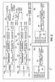
- FIGS. 2-4illustrate components of an exemplary distributed antenna system for implementing embodiments of the invention.
- FIG. 2contains a detailed block diagram of the master unit 18 .
- Each master unit 18may contain one or more radio channels 110 (typically from one to six radio channels 110 , each hereinafter referred to as a “path”), one or more digitally modulated optical channels 112 (typically from one to four digitally modulated optical channels 112 ), a controller 114 , a clock generator 116 , and an Ethernet switch 118 .
- each pathsuch as 110 a
- each pathmay be configured to handle a signal to and from the MIMO BTS 12 , for example.
- the paths 110 aemploy a combiner and a duplexer 120 to handle the uplink signal and the downlink signal.
- An RF downconverter 122may amplify the received signal from the combiner/duplexer 120 to ensure that an A/D converter 124 is fully loaded.
- the RF downconverter 122sets a center frequency of a band within the A/D converter pass band.
- the wideband A/D 124digitizes the entire downlink band of the air interface to ensure all downlink channels are digitized.
- a resampler 126converts the signal to a complex format, digitally downconverts the frequency band in some cases, decimates and filters the signal, and resamples it. This reduces the amount of data associated with a downlink signal, such as 128 a , that has to be transferred over the optical lines and synchronizes the rate of the digitized data to the optical network bit rate.
- the uplink section of the radio channel 110 asums 120 the uplink signals, such as signals 129 a - d , for its assigned band from remote units 24 coupled to the master unit 18 after they are converted to an electrical signal.
- the summation 130is resampled, interpolated to change to a different data rate in some cases, and upconverted by the resampler 132 and then converted to an analog form by the D/A converter 134 .
- the RF upconverter 136translates the center frequency of the analog signal to the appropriate frequency for the air interface and amplifies it.
- the amplified signalis applied to the combiner/duplexer 120 and is routed back to the MIMO BTS 12 .
- the combiner and duplexerare replaced by a switching function 138 shown in FIG. 2 for example in radio channel 110 b .
- a RF amplifier in the RF upconverteris disabled and a shunt switch in the switching function 138 may shunt the RF amplifier to ground to further reduce leakage.
- the RF amplifieris enabled, the shunt switch is opened and a series switch in the switching function 138 may be opened to protect the RF downconverter from damage due to high power levels.
- the switch control timing 144is determined by a master unit controller 114 from the downlink signal 128 b .
- a formatter 146may apply a data compression to reduce the redundant digital information included in the serial data stream before it is sent to the transmitter in an electro-optical transceiver 148 .
- the compressionmay allow for saving bandwidth or for using a less costly transceiver with lower bit rate.
- the compressed serial datamay be converted into an uncompressed data stream after being received on the opposite ends in the optical received of 148 by the receiver side formatter 146 .
- Each digitally modulated optical channel 112 a - bis composed of a formatter 146 and an electro-optical transceiver 148 .
- the formatter 146blocks, into time division multiplexed frames, the digitized downlink signal 128 a - b along with a customer Ethernet in Reduced Media Independent Interface (“RMII”) format 150 a - b , operation and maintenance (“O&M”) data 152 a - c and synchronization information.
- RMIIReduced Media Independent Interface
- O&Moperation and maintenance
- other interfacessuch as MII, RMII, GMII, SGMII, XGMII, among others may be used in place of the RMII interface.
- the framed datamay be randomized by exclusive or'ing (XOR) it with the output of a linear feedback shift register to remove long strings of logic ones or zeros.
- XORexclusive or'ing
- Other known coding formatssuch as 8 bit/10 bit or 64 bit/66 bit coding may also be used, but may result in a decrease in efficiency in the use of the digital serial link.
- This digital datais then converted to a serial stream which is used to modulate an optical transmitter within the electro-optical transceiver 148 .
- a wavelength division multiplexer (WDM) 149may be employed to combine or split the two optical signals.
- the electro-optical transceiver 148converts the optical signal to an electrical signal.
- the formatter 146phaselocks to the incoming bit stream and generates a bit clock that is phaselocked to the data rate and aligned with the serial data stream.
- the formatter 146then converts the serial stream to a parallel digital data stream, de-randomizes it and performs frame synchronization. It then breaks out the digitized uplink signal for each band, buffers each band and routes the bands to the appropriate radio channel 110 a , 110 b , if necessary.
- the formatter 146breaks out the buffers and O&M Ethernet data 152 a - c and the user Ethernet data 150 a - b and routes them to the controller 114 and the Ethernet switch 118 , respectively.
- the master unit controller 114uses locally stored information and information from the O&M Ethernet data to configure and control the other blocks in the master unit 18 . It also passes this information to the remote units 24 and reports status of the remote units 24 and the master unit 18 to the system controller 27 .
- a radio channelsuch as 110 b
- the master unit controller 114also uses the corresponding downlink signal 128 b to derive TDD switch control timing 144 .
- the master unit controller 114functions to configure individual modules as well as supervise individual modules. As part of the configuration and supervision functions, the master unit controller 114 is operable to determine the uplink/downlink switch timing in TDD systems by decoding the downlink signaling or acquiring it from a different source such as the time variant uplink Received Signal Strength Indication (“RSSI”), or some base station clock signal provided from an external source.
- RSSItime variant uplink Received Signal Strength Indication
- the downlink frame clock in TDMA systemsmay be determined and distributed by decoding the downlink signaling to allow time slot based functions such as uplink or downlink muting, uplink or downlink RSSI measurements within time slots, uplink and downlink traffic analysis, etc.
- the master unit controller 114may detect active channels in the RF spectrum to assist in or automatically configure the filter configuration in the resampler 126 , 132 . Optimal leveling of the individual signals in the resampler may also be determined by measurement of the RSSI of the various signals in the downlink RF band. A remote unit controller may perform similar tasks in the uplink of the remote unit 24 .
- the clock generator 116may use a stable temperature compensated voltage controlled crystal (“TCVXO”) to generate stable clocks and reference signals 154 for master unit 18 functional blocks.
- TCVXOtemperature compensated voltage controlled crystal
- other devices or crystalsmay also be used to generate clocking signals as long as they are capable of producing the stable clocks required by the system.
- FIG. 3A and FIG. 3Bcontain a detailed block diagram of a remote unit 24 consistent with embodiments of the invention.
- Each unit 24may contain one or more radio channels 160 (typically from one to six radio channels 160 ), one or more DMOCs 162 (typically one or two DMOCs 162 ), a remote unit controller 164 and an Ethernet switch 166 .
- the DMOCs 162may be designated as the downstream 168 and upstream channels 170 .
- the downstream channel 168is connected to a remote unit 24 that precedes this remote unit 24 in a daisy chain, if so configured.
- the upstream channel 170is connected to a master unit 18 or another remote unit 24 .
- the DMOC 162 functional blocksare similar to those in the master unit 18 . Both consist of a formatter 172 and electro-optical transceiver 174 . Outgoing data is buffered, formatted into frames, randomized, parallel to serial converted and used to modulate an optical transmitter in the electro-optical transceiver 174 .
- Incoming datais converted from an optical to electrical format, bit synchronized, de-randomized, frame synchronized and converted to a parallel format.
- the various data typesare then broken out buffered and distributed to other function blocks within the remote unit 24 .
- formatter 172may implement compression and decompression schemes to reduce bandwidth over the digital optical link.
- Radio channels in the remote unit 24are functionally similar to those in the master unit 18 . Each radio channel is configured to handle a single RF band. Unlike the master unit 18 radio channels 110 , the remote unit 24 radio channels 160 are connected via a cross band coupler 176 to its antenna 25 . For FDD air interfaces, the radio channels, such as radio channel 160 a , employ a duplexer 178 to split the uplink and the downlink signal. Duplexers, cross-band combiners and couplers may be optional for some embodiments of either the master unit 18 or remote units 24 . In these embodiments, additional antennas may replace the duplexer 178 and cross-coupler 176 in the remote units 42 . Extra cables would be required in the master unit 18 .
- An RF downconverter 180amplifies the received uplink signal from the antenna 25 to ensure an A/D converter 182 is fully loaded and sets the center frequency of the band within the A/D converter pass band.
- the wideband A/D 182digitizes the entire uplink band of the air interface to ensure all uplink channels are digitized.
- a resampler 184converts the uplink signal to a complex format, digitally downconverts the signal in some cases, decimates and filters the signal, and resamples it with a multi-rate filter bank. This reduces the amount of data that has to be transferred over the optical links and synchronizes the rate of the digitized data to the optical network bit rate.
- the output of the resampler 184is added to the uplink signals 186 a from the downstream remote units 24 in summer 187 .
- the summed uplink signal 188 a for each bandis then sent to a formatter 172 in the upstream channel 170 in the DMOC 162 .
- the downlink signal 190 for each band( 190 a , 190 b ) is interpolated and frequency shifted in the resampler 192 .
- the group delay of individual spectral componentscan be adjusted via filters or delay elements in the resampler 192 .
- the signalis then converted to an analog form by the D/A converter 194 .
- the RF upconverter 196translates the center frequency of the analog downlink band to the appropriate frequency for the air interface and amplifies it.
- the amplified signalis then applied to the antenna 25 and transmitted to a wireless device 32 .
- the duplexer 178is replaced by the switching function 138 shown in radio channel 160 b and FIG. 3A .
- the RF power amplifier in the RF upconverter 196is disabled and a shunt switch in the switching function 138 shunts the RF power amplifier to ground to further reduce leakage.
- the RF power amplifieris enabled, the shunt switch is opened to permit the downlink signal to reach the antenna 25 and a series switch in the switching function 138 is opened to protect the RF downconverter 180 from damage due to high power levels.
- the switch control timing 144is determined by the controller 164 from the downlink signal 190 a , 190 b.
- the clock generator 198includes a voltage-controlled crystal oscillator (“VCXO”) that is phaselocked to the incoming serial data stream bit rate via a narrowband phaselocked loop (“PLL”).
- the VCXO outputis split and is used as the frequency reference 200 for the local oscillators in each radio channel 160 a - b , the sampling clocks for the A/D 182 and D/A 194 converters, and a clock for the other blocks in the remote unit 24 .
- VCXOvoltage-controlled crystal oscillator
- PLLnarrowband phaselocked loop
- the remote unit 24does not require an expensive oven compensated oscillator or a GPS disciplining scheme to maintain long term frequency accuracy, thereby, making the more numerous remote units 24 less expensive.
- the use of a narrow band PLL and a crystal controlled oscillatormay assist in reducing short term jitter for the A/D and D/A converter clocks.
- jitter reduced clocks 202to re-clock the transmit data in the optical links at each remote unit 24 reduces jitter accumulation which may assist in improving A/D and D/A converter clocks in the downstream remote units 24 and may assist in reducing the bit error rate (“BER”) of the optical communication channels 162 .
- BERbit error rate
- the remote unit controller (RUC) 164uses locally stored information and information from the O&M Ethernet to configure and control the other blocks in the remote unit 24 .
- Downstream RMII 152 d and upstream RMII 152 emay also be supplied to the formatter 172 .
- local O&M data 206may be configured at a local O&M terminal 204 .
- Remote unit 24also passes this information to the up and downstream remote units 24 and/or master unit 18 .
- the RUC 164additionally uses the appropriate downlink signal to derive TDD switch control timing 144 when required.
- the radio channel 160 cmay also employ digital pre-distortion to linearize the power amplifier.
- This embodiment of the radio channel 160 c in a remote unit 24is shown in the block diagram of FIG. 4 .
- a third signal pathmay be added to one or more radio channels 160 c .
- the third pathcouples off the downlink signal after power amplification and digitizes it.
- the signal from the antenna 25is received in an RF downconverter 208 , which amplifies the received signal to ensure an A/D converter 210 is fully loaded and sets the center frequency of the band within the A/D converter pass band.
- the wideband A/D 210digitizes the entire uplink band of the air interface to ensure all uplink channels are digitized.
- the digitized signalis compared to a delayed version of the downlink signal in the digital pre-distortion unit 212 and the difference is used to adaptively adjust the gain and the phase of the signal prior to D/A conversion to correct for non-linearity in the power amplifier.
- the topology of a system 10can be adjusted to optimize MIMO channel capacity.
- Eq. 1illustrates a MIMO channel capacity formula for an N ⁇ M MIMO system with equal power allocation to each antenna 25 :
- the MIMO channel capacitydepends on several parameters that have to be taken into account for its optimization.
- prepresents the signal-to-noise and interference ration (SNIR) averaged over the receiving antennas.
- the H MIMO channel matrixincludes the different H ij channel transfer functions between the “i” receiving and “j” transmitting antennas.
- the MIMO channel matrixis normalized so that the path-loss effect on its coefficients is removed and included into the SNIR parameter. As a result, the MIMO channel matrix is only affected by the level of correlation experienced at the antennas.
- the MIMO capacity formulacan also be written in terms of the Eigen-values ⁇ k of the MIMO channel matrix, with k ranging from 1 to the MIMO channel matrix rank R.
- the Eigen-valuesrepresent an indicator of the correlation affecting the MIMO channel. As such, they provide a measure of the MIMO channel's ability to support multiple spatial streams in order to increase the resulting capacity.
- the channel condition number(CCN), which is the ratio between the smallest Eigen-value and largest Eigen-value, can be exploited as an additional parameter to measure how conditioned the MIMO channel matrix is.
- the CCNapproaches the 0 dB value, which means the Eigen-values are all equal and spatial multiplexing can be successfully exploited by virtue of low correlation (e.g., the system can utilize SU-MIMO modes of operation).
- the CCNcan jump to 20 dB or even more, which means the channel is highly correlated and it is not able to support spatial multiplexing (e.g., the system cannot utilize SU-MIMO modes of operation).
- FIG. 5is a graph 300 illustrating the channel capacity percentage increase as a function of the SNIR, and that further illustrates, for a given environment, that the optimization of MIMO channel capacity depends upon the optimization of the SNIR and the CCN.
- the graph 300was generated with a 2 ⁇ 2 MIMO system deployed in an indoor environment, such as illustrated in FIG. 1 .
- the CCNprovides an indication on the correlation level affecting the MIMO channel and depends upon several factors, including the scattering properties of the specific environment involved (e.g., rich or poor), the MIMO Tx antenna array spacing (e.g., ranging from ⁇ /2 up), the antenna polarization, the Tx and Rx position (e.g., Line of Sight [LoS] positioning, Not Line of Sight [NLoS] positioning), as well as other factors.
- three general indoor environmentsinclude dense environments (e.g., filled with objects), open environment (e.g., generally devoid of objects), and large environments (e.g., associated with large distances between antennas).
- FIG. 6is an illustration of a graph 310 that shows the typical CCN distribution in a “dense” indoor environment with co-polarized antennas
- FIG. 7is an illustration of a graph 320 that shows the typical CCN distribution in an “open” indoor environment with co-polarized antennas
- FIG. 8is an illustration of a graph 330 that shows the typical CCN distribution in a “large” indoor environment with co-polarized antennas.
- embodiments of the inventionare utilized to keep the channel correlation and resulting CCN low by selectively placing antennas (e.g., remote units) in an environment based on the imbalance of received power and SNIR associated with those antennas.
- the antennasare placed in an environment such that wireless devices can receive power contributions from at least two antennas throughout the environment. More specifically, embodiments of the invention specify the power imbalance as well as the SNIR required to have a particular capacity within that area.
- wireless devicesreceive substantial power contributions from several antennas deployed throughout the environment.
- the antenna deploymentprovides wireless devices with LoS channel conditions from each antenna throughout the environment such that both low spatial correlation and high SNIR conditions are achieved.
- this solutionis often associated with high costs due to the large number of antennas that may be necessary.
- FIG. 9is an illustration of an indoor environment 400 in which four antennas 25 a , 25 a ′, 25 b and 25 b ′ have been distributed, and in which various imbalances between two signals of a 2 ⁇ 2 MIMO DAS (e.g., such as the system 10 of FIG. 1 ) have been measured.
- the power imbalance of received signalsis determined by a wireless device or a mobile test set-up (or equivalent equipment). Specifically, the device or test set-up determines the received power of a first signal, the received power of a second signal, and determines the absolute value of the difference of the received power of those two signals to determine the power imbalance of the received signals.
- like reference numeralsare utilized in FIG. 9 where applicable.
- Antennas 25 a and 25 a ′are configured to communicate a first MIMO signal, while antennas 25 b and 25 b ′ are configured to communicate a second MIMO signal.
- each antenna 25 a , 25 a ′, 25 b and 25 b ′are connected to a respective remote units 24 (not shown), while in alternative embodiments antennas 25 a and 25 a ′ are connected to a first remote unit 24 a and antennas 25 b and 25 b ′ are connected to a second remote unit 24 b .
- a wireless device or mobile test set-up (or equivalent equipment)may then determine the power imbalance between the first and second received signals as shown at the illustrated data points. As illustrated in FIG.
- the interleaved antennas 25 a , 25 a ′, 25 b and 25 b ′provide good coverage uniformity and substantial overlapping between coverage areas.
- the relation between the received power imbalances from the signals from the antennas 25 a or 25 a ′ and the antennas 25 b or 25 b ′correspond to a particular CCN.
- FIG. 10is a graph 410 illustrating the effect of an imbalance of the received power of two signals on the CCN when that imbalance is less than about 5 dB
- FIG. 11is a graph 420 illustrating the effect of an imbalance of the received power of two signals on the CCN when that imbalance is from about 5 dB to about 10 dB
- FIG. 12is a graph 430 illustrating the effect of an imbalance of the received power of two signals on the CCN when that imbalance is from about 10 dB to about 15 dB
- FIG. 13is a graph 440 illustrating the effect of an imbalance of the received power of two signals on the CCN when that imbalance is greater than about 15 dB.
- the CCNassumes a low value, while a high power imbalance (e.g., more than 15 dB) is associated with a CCN of 20 dB or more.
- a low power imbalancee.g., less than 5 dB
- a high power imbalancee.g., more than 15 dB
- the CCNis driven by the power imbalance parameter rather than channel correlation.
- embodiments of the inventiondetermines the imbalance of the received power from two interleaved antennas, as well as the SNIR experienced at that point.
- a userdetermines the CCN from that power imbalance, then correlates the CCN and SNIR to a datastore (e.g., a database, graph, or other collection) of information to determine the MIMO capacity of a MIMO system with the antennas at their selected locations.
- FIG. 14is datastore in the form of a graph 450 illustrating the effect of the CCN and SNIR with the capacity of a MIMO system with interleaved antennas according to the invention.
- FIG. 15is a flowchart 500 illustrating a sequence of operations to selectively determine a location to deploy a plurality of remote units, or a plurality of antennas of remote units, to optimize the capacity of a MIMO DAS in an environment consistent with embodiments of the invention.
- a userdeploys a first antenna at a first location that may be desirable from a signal coverage standpoint (block 502 ).
- a userdeploys a second antenna at a second location (block 504 ).
- An imbalance between the received power of signals from the first antenna and the received power of signals from the second antennais then determined at a predetermined location (e.g., a “power imbalance”) (block 506 ).
- a predetermined locatione.g., a “power imbalance”
- a CCN and SNIR for the signals at the predetermined locationis determined (block 508 ) and the capacity of the MIMO DAS with the first antenna at the first location and the second antenna at the second location is determined (block 510 ).
- a datastore of the relationship between the CCN and the SNIRmay be utilized to determine the capacity of the MIMO DAS.
- the capacityis not acceptable (e.g., the capacity of the MIMO DAS is not high enough for a desired installation) (“No” branch of decision block 512 )
- the useradjusts the location of deployment of the second antenna (block 514 ) and the sequence of operations returns to block 506 .
- the capacityis acceptable (e.g., the capacity of the MIMO DAS is high enough for a desired installation) (“Yes” branch of decision block 512 ) the sequence of operations ends.
- FIG. 16is a flowchart 520 illustrating a sequence of operations for a user to selectively tune the operation of a MIMO DAS in either a SU-MIMO mode of operation or a MU-MIMO mode of operation based upon a power imbalance consistent with embodiments of the invention.
- the userdeploys a first antenna at a first location (block 522 ) and deploys a second antenna at a second location (block 524 ).
- a power imbalance between signals from the first and second antennasis then determined at a predetermined location (block 526 ).
- the power imbalance between signals from the first and second antennascan be used to tune a MIMO DAS to more efficiently utilize SU-MIMO and MU-MIMO modes of operation. As such, it is determined whether the power imbalance is below a predetermined threshold, such as about 15 dB (block 528 ). When the power imbalance is below the predetermined threshold (“Yes” branch of decision block 528 ) it is determined whether the MIMO DAS is configured to utilize SU-MIMO modes of operation (block 530 ). When the MIMO DAS is not going to be utilized with SU-MIMO modes of operation (“No” branch of decision block 530 ), the location of the deployment of the second antenna is adjusted to increase the power imbalance (block 532 ) and the sequence of operations returns to block 526 .
- a predetermined thresholdsuch as about 15 dB
- the MIMO DASWhen the MIMO DAS is configured to utilize SU-MIMO modes of operation (“Yes” branch of decision block 530 ), it is determined whether the capacity for the MIMO DAS is acceptable (block 534 ). When the capacity is not acceptable (“No” branch of decision block 534 ) the location of the deployment of the second antenna is adjusted to increase the capacity of the MIMO DAS (block 536 ). However, when the capacity is acceptable (“Yes” branch of decision block 534 ) the sequence of operations ends.
- the CCNcorresponds to the RF power imbalance of two signals.
- the interleaving of antennas using a DAS signalgives an advantage in terms of the capacity, C, when compared to classical MIMO deployments based on coverage with a plurality of antennas as well as co-located antenna arrays.
- the position of each remote unit or antennais the driver for building radio coverage within an environment to exploit the maximum capacity C in accordance with the invention.
- userscan employ a ray-tracing simulator, algorithm, or other equivalent simulation to determine the optimized position of each antenna to provide a maximum C within an environment or to optimize the operation of a system for either MU-MIMO or SU-MIMO modes of operation.
- a ray-tracing simulator, algorithm, or other equivalent simulationcan be performed by a computing system, or otherwise integrated into program code executed by the computing system.
- Such a computing systemtypically includes one or more processors coupled to a memory.
- the computing systemalso typically includes at least one network interface coupled to at least one network, as well as at least one input/output device interface coupled to at least one peripheral device, such as a user interface (including, for example, a keyboard, mouse, a microphone, and/or other user interface) and/or at least one output device (including, for example, a display, speakers, a printer, and/or another output device).
- a user interfaceincluding, for example, a keyboard, mouse, a microphone, and/or other user interface
- at least one output deviceincluding, for example, a display, speakers, a printer, and/or another output device.
- Such computer systemsare often under the control of an operating system and execute, or otherwise rely upon, various computer software applications, sequences of operations, components, programs, files, objects, modules, etc., consistent with embodiments of the invention.
- a first remote unit or antennamay be placed inside an environment according to well know radio coverage design rules (e.g., for example, in an already installed SISO system).
- a second remote unitmay be placed in a different position to achieve, from the two different paths and for the whole in-building area or other environment under consideration, an RF power imbalance below to a given limit, such as about 15 dB, for example.
- the proper placement of the second remote unitcan be determined at least three different ways: (1) exploiting SISO radio coverage design rules with the goal to maximize the area of the environment where the RF power imbalance is below a predetermined limit (for example, using a SISO radio coverage SW tool); (2) running different trials in which different locations for the second antenna are attempted and exploiting a wireless device or other mobile test-set (or equivalent equipment) to maximize the coverage area where the RF power imbalance is below the predetermined limit, including finding the location for the second antenna that takes advantage of the scattering or shadowing effect of the environment; or (3) if it is infeasible to try several locations for the second antenna, an approximate location for the second antenna can be used and, from the same wireless device or other mobile test-set (or equivalent equipment), information on the RF power imbalance and SNIR from the first remote unit can be gathered in order to delimit/analyze the coverage area where a particular capacity C for the MIMO system can be guaranteed.
- a predetermined limitfor example, using a SISO radio coverage SW tool
- a usermay determine a desired layout of antennas and/or remote units throughout the target environment based upon the existing coverage of that environment, the coverage that can be provided by antennas and/or remote units, and cost considerations. In some embodiments, this determination can be made by analyzing known and/or potential coverages, capacities, and costs of purchasing, installing, and maintaining equipment (remote units, cabling therefore, etc.). The user then selects a layout that provides the desired coverage with the desired capacity within a desired budget.
- FIG. 17is a diagrammatic illustration of a MIMO DAS 600 that includes co-located remote antennas 25 a - b within an environment 602 .
- the MIMO DAS 600includes a 2 ⁇ 2 MIMO BTS 12 that provides respective MIMO signals to respective master units 18 a - b .
- the antennas 25 a - bcan be connected to respective remote units 24 a - b (not shown) or connected directly to the master units 18 a - b .
- the MIMO DAS 600provides a particular coverage area 604 with the antennas 25 a - b.
- the coverage area 604 in the environment 602may provide signals to only one of three wireless devices 606 a - c , with wireless devices 606 a and 606 c unable to receive signals from either antenna 602 a - b (as they are both outside of coverage area 604 ) and wireless device 606 b receiving signals from both antennas 25 a - b .
- the wireless device 606 bcan utilize SU-MIMO modes of operation, and thus experience a data rate boost, as well as experience transmit diversity against fast fading.
- this particular setupprovides the smallest coverage for the environment 602 , provides no coverage for wireless devices 606 a and 606 c , results in a high correlation, and also has a limited sector capacity for either DL or UL MU-MIMO.
- FIG. 18is a diagrammatic illustration of a MIMO DAS 610 in which the remote antennas 25 a - b are distributed within the environment 602 but have overlapping coverage areas 612 a - b .
- FIG. 18illustrates that wireless devices 606 a and 606 b are within the coverage area 612 a for the first antenna 25 a
- wireless devices 606 b and 606 care within the coverage area 612 b for the second antenna 25 b .
- there is low correlation and transmit diversity against slow fading for wireless device 606 bwhich can utilize SU-MIMO modes of operation.
- FIG. 18illustrates that a high sector capacity for MU-MIMO is achieved by distributing the antennas 25 a - b .
- this configurationresults in a limited data rate boost for wireless device 606 b and does not provide transmit diversity against fast fading.
- FIG. 19is a diagrammatic illustration of a MIMO DAS 620 in which the remote antennas 25 a - b are distributed within the environment 602 but do not have overlapping coverage areas 622 a - b .
- FIG. 19illustrates that wireless devices 606 a is within coverage area 622 a , that wireless device 606 b is within either coverage area 622 a or 622 b (but not both at the same time), and that wireless device 606 c is within coverage area 622 b .
- the coverage areas 622 a and 622 bdo not overlap.
- the largest SISO coverage for the environment 602is provided.
- wireless devices 606 a and 606 ccan share resources and utilize MU-MIMO modes of operation.
- the MIMO DAS 620also has a higher sector capacity for MU-MIMO modes of operation than either the MIMO DAS 600 of FIG. 17 or the MIMO DAS 610 of FIG. 18 .
- wireless device 606 bdoes not have a data rate boost and cannot operate in SU-MIMO modes of operation, as it only receives signals from one antenna 252 a or 252 b .
- a distributed antenna systemconsistent with embodiments of the invention may have more or fewer MIMO BTSs 12 , master units 18 , remote units 24 , and/or system controllers 27 than those illustrated.
- each MIMO BTS 12may include more or fewer antennas 14 and/or 16 .
- each master unit 18may be connected to more or fewer remote units 24 than those illustrated. As such, a plurality of remote units 24 may be connected to each master unit 18 through two links and/or along a single link as discussed above. Alternatively, each remote unit 24 may be connected to a master unit 18 through a dedicated link. In some embodiments, a plurality of remote units 24 may be connected in series from a master unit 18 . As such, remote units 24 may be positioned to optimize coverage within a coverage area consistent with embodiments of the invention. Moreover, one having ordinary skill in the art will appreciate that a master unit 18 may be incorporated with a remote unit 24 , and thus operate as an active (or passive) distribution point as is well known in the art.
- each such master unit 18may be connected directly to at least one antenna 25 .
- a passive (or active) power splittercan be inserted in order to deploy additional remote units.
- each such master unit 18 input/output portmay be coupled with a plurality of remote units 24 consistent with embodiments of the invention.
- the master unit controller 114may measure a pilot signal strength of CDMA or Orthogonal Frequency-Division Multiplexing (“OFDM”) signals to properly set the level of the downlink signals, as the RSSI can vary at different capacity loading.
- the pilot signalsgenerally remain constant with a configured ratio between pilot level and a maximum composite for full loading, the required headroom for the signals may be maintained.
- the master unit controller 114may also measure and supervise the signal quality of the provided downlink channels. In case of signal degradation, an alarm may be set and the operator can focus on a base station (e.g., the MIMO BTS 12 ) without having to troubleshoot the entire system 10 .
- the master unit controller 114determines the amount of channels for a narrowband base station standard such as Global System for Mobile communications (“GSM”). Together with the measurement of the Broadcast Control Channel (“BCCH”), which is constant in power, the proper headroom that is required for a multichannel subband may be determined and overdrive or underdrive conditions may be avoided.
- GSMGlobal System for Mobile communications
- BCCHBroadcast Control Channel
- the master unit controller 114monitors the crest factor of a transmitted spectrum in the presence of multiple channels. The crest factor may provide input to the leveling of the transmit power or the power back-off of particular gain stages of the system.
- the configured headroomis generally higher than the measured crest factor to avoid signal degradation due to clipping or distortion.
- a crest factor reduction mechanismmay be employed in the resampler in some of the embodiments to reduce the crest factor and make more efficient use of the RF power amplifier in the remote unit 24 or assist in reducing the number of required bits per sample that need to be transmitted over the link.
- Some embodiments of the inventionprovide benefits in regard to the uplink path of a MIMO communication system.
- WiMAX and LTE wireless standardsencompass uplink MIMO features.
- the “Uplink Collaborative MIMO”is implemented in Mobile WiMAX
- “Uplink MU-MIMO”is the term adopted in LTE for indicating the same technique.
- the peculiarity of this MIMO schemeis to increase the total uplink sector capacity by reusing time/frequency resources allocated to different wireless devices 32 , rather than to boost the data rate per single user as for downlink SU-MIMO (Spatial Multiplexing).
- routines executed to implement embodiments of the inventionwhether implemented as part of an operating system or a specific application, component, scheduler, program, object, module or sequence of instructions executed by one or more computing systems have been referred to herein as a “sequence of operations,” a “program product,” or, more simply, “program code.”
- the program codetypically comprises one or more instructions that are resident at various times in various memory and storage devices, and that, when read and executed by one or more processors, cause that a system associated with that processor to perform the steps necessary to execute steps, elements, and/or blocks embodying the various aspects of the invention.
- computer readable signal bearing mediainclude but are not limited to physical and tangible recordable type media such as volatile and nonvolatile memory devices, floppy and other removable disks, hard disk drives, optical disks (e.g., CD-ROM's, DVD's, etc.), among others, and transmission type media such as digital and analog communication links.
- the system 10 of FIG. 1may be configured with an extension unit (not shown) disposed between a master unit 18 and its corresponding remote units 24 .
- the extension unitmay provide additional links for coupling a master unit 18 to additional remote units 24 and/or the extension unit may extend the range of coupling between a master unit 18 and remote units 24 .
- the environments 26 , 400 , and 602are merely included to show operation of embodiments of the invention therewith, and that embodiments of the invention may be used with indoor or outdoor environments without departing from the scope of the applicants' general inventive concept.
- the indoor environment 26 of FIG. 1 and the indoor environment 400 of FIG. 9are configured in alternative manners than those illustrated.
Landscapes
- Engineering & Computer Science (AREA)
- Computer Networks & Wireless Communication (AREA)
- Signal Processing (AREA)
- Quality & Reliability (AREA)
- Physics & Mathematics (AREA)
- Electromagnetism (AREA)
- Mobile Radio Communication Systems (AREA)
- Radio Transmission System (AREA)
Abstract
Description
| TABLE 1 |
| Pre-Coding Codebook for Transmission on Two Antennas |
| Number of layers υ |
| 1 | 2 | |
| 0 | ||
| 1 | ||
| 2 | ||
| 3 | — | |
| TABLE 2 |
| CQI Table |
| CQI | Code Rate × | ||||
| Index | Modulation | 1024 | |||
| 0 | out of |
| 1 | QPSK | 78 | 0.1523 | ||
| 2 | QPSK | 120 | 0.2344 | ||
| 3 | QPSK | 193 | 0.3770 | ||
| 4 | QPSK | 308 | 0.6016 | ||
| 5 | QPSK | 449 | 0.8770 | ||
| 6 | QPSK | 602 | 1.1758 | ||
| 7 | 16QAM | 378 | 1.4766 | ||
| 8 | 16QAM | 490 | 1.9141 | ||
| 9 | 16QAM | 616 | 2.4063 | ||
| 10 | 64QAM | 466 | 2.7305 | ||
| 11 | 64QAM | 567 | 3.3223 | ||
| 12 | 64QAM | 666 | 3.9023 | ||
| 13 | 64QAM | 772 | 4.5234 | ||
| 14 | 64QAM | 873 | 5.1152 | ||
| 15 | 64QAM | 948 | 5.5547 | ||
Claims (20)
Priority Applications (1)
| Application Number | Priority Date | Filing Date | Title |
|---|---|---|---|
| US15/707,826US10644761B2 (en) | 2010-02-12 | 2017-09-18 | Distributed antenna system for MIMO communications |
Applications Claiming Priority (7)
| Application Number | Priority Date | Filing Date | Title |
|---|---|---|---|
| ITBO2010A000077AIT1398025B1 (en) | 2010-02-12 | 2010-02-12 | DISTRIBUTED ANTENNA SYSTEM FOR MIMO COMMUNICATIONS. |
| ITBO2010A000077 | 2010-02-12 | ||
| PCT/US2011/023991WO2011100219A1 (en) | 2010-02-12 | 2011-02-08 | Distributed antenna system for mimo communications |
| US13/025,697US8744504B2 (en) | 2010-02-12 | 2011-02-11 | Distributed antenna system for MIMO communications |
| US14/291,321US9413439B2 (en) | 2010-02-12 | 2014-05-30 | Distributed antenna system for MIMO communications |
| US15/231,596US9768840B2 (en) | 2010-02-12 | 2016-08-08 | Distributed antenna system for MIMO communications |
| US15/707,826US10644761B2 (en) | 2010-02-12 | 2017-09-18 | Distributed antenna system for MIMO communications |
Related Parent Applications (1)
| Application Number | Title | Priority Date | Filing Date |
|---|---|---|---|
| US15/231,596ContinuationUS9768840B2 (en) | 2010-02-12 | 2016-08-08 | Distributed antenna system for MIMO communications |
Publications (2)
| Publication Number | Publication Date |
|---|---|
| US20180069607A1 US20180069607A1 (en) | 2018-03-08 |
| US10644761B2true US10644761B2 (en) | 2020-05-05 |
Family
ID=42237435
Family Applications (4)
| Application Number | Title | Priority Date | Filing Date |
|---|---|---|---|
| US13/025,697Active2032-06-18US8744504B2 (en) | 2010-02-12 | 2011-02-11 | Distributed antenna system for MIMO communications |
| US14/291,321Expired - Fee RelatedUS9413439B2 (en) | 2010-02-12 | 2014-05-30 | Distributed antenna system for MIMO communications |
| US15/231,596ActiveUS9768840B2 (en) | 2010-02-12 | 2016-08-08 | Distributed antenna system for MIMO communications |
| US15/707,826ActiveUS10644761B2 (en) | 2010-02-12 | 2017-09-18 | Distributed antenna system for MIMO communications |
Family Applications Before (3)
| Application Number | Title | Priority Date | Filing Date |
|---|---|---|---|
| US13/025,697Active2032-06-18US8744504B2 (en) | 2010-02-12 | 2011-02-11 | Distributed antenna system for MIMO communications |
| US14/291,321Expired - Fee RelatedUS9413439B2 (en) | 2010-02-12 | 2014-05-30 | Distributed antenna system for MIMO communications |
| US15/231,596ActiveUS9768840B2 (en) | 2010-02-12 | 2016-08-08 | Distributed antenna system for MIMO communications |
Country Status (4)
| Country | Link |
|---|---|
| US (4) | US8744504B2 (en) |
| EP (3) | EP3364553B1 (en) |
| IT (1) | IT1398025B1 (en) |
| WO (1) | WO2011100219A1 (en) |
Cited By (1)
| Publication number | Priority date | Publication date | Assignee | Title |
|---|---|---|---|---|
| US11690135B2 (en)* | 2019-09-26 | 2023-06-27 | Commscope Technologies Llc | Passive backplane architecture for master unit of distributed antenna system |
Families Citing this family (148)
| Publication number | Priority date | Publication date | Assignee | Title |
|---|---|---|---|---|
| IT1403065B1 (en) | 2010-12-01 | 2013-10-04 | Andrew Wireless Systems Gmbh | DISTRIBUTED ANTENNA SYSTEM FOR MIMO SIGNALS. |
| US8873585B2 (en) | 2006-12-19 | 2014-10-28 | Corning Optical Communications Wireless Ltd | Distributed antenna system for MIMO technologies |
| US9276656B2 (en) | 2007-02-19 | 2016-03-01 | Corning Optical Communications Wireless Ltd | Method and system for improving uplink performance |
| US20100054746A1 (en) | 2007-07-24 | 2010-03-04 | Eric Raymond Logan | Multi-port accumulator for radio-over-fiber (RoF) wireless picocellular systems |
| US8175459B2 (en) | 2007-10-12 | 2012-05-08 | Corning Cable Systems Llc | Hybrid wireless/wired RoF transponder and hybrid RoF communication system using same |
| US8594133B2 (en) | 2007-10-22 | 2013-11-26 | Corning Mobileaccess Ltd. | Communication system using low bandwidth wires |
| US8175649B2 (en) | 2008-06-20 | 2012-05-08 | Corning Mobileaccess Ltd | Method and system for real time control of an active antenna over a distributed antenna system |
| US8644844B2 (en) | 2007-12-20 | 2014-02-04 | Corning Mobileaccess Ltd. | Extending outdoor location based services and applications into enclosed areas |
| JP2010109631A (en)* | 2008-10-29 | 2010-05-13 | Kyocera Corp | Wireless communication system, transmission device, and communication signal transmission method |
| CN102369678B (en) | 2009-02-03 | 2015-08-19 | 康宁光缆系统有限责任公司 | Optical fiber based distributed antenna systems, assemblies and related methods for calibrating optical fiber based distributed antenna systems, assemblies |
| CN102396171B (en) | 2009-02-03 | 2015-09-30 | 康宁光缆系统有限责任公司 | Based on the distributing antenna system of optical fiber, assembly and the correlation technique for monitoring and configure distributing antenna system based on optical fiber, assembly |
| US9673904B2 (en) | 2009-02-03 | 2017-06-06 | Corning Optical Communications LLC | Optical fiber-based distributed antenna systems, components, and related methods for calibration thereof |
| WO2010089719A1 (en) | 2009-02-08 | 2010-08-12 | Mobileaccess Networks Ltd. | Communication system using cables carrying ethernet signals |
| US8346091B2 (en) | 2009-04-29 | 2013-01-01 | Andrew Llc | Distributed antenna system for wireless network systems |
| US9590733B2 (en) | 2009-07-24 | 2017-03-07 | Corning Optical Communications LLC | Location tracking using fiber optic array cables and related systems and methods |
| US8548330B2 (en) | 2009-07-31 | 2013-10-01 | Corning Cable Systems Llc | Sectorization in distributed antenna systems, and related components and methods |
| US8280259B2 (en) | 2009-11-13 | 2012-10-02 | Corning Cable Systems Llc | Radio-over-fiber (RoF) system for protocol-independent wired and/or wireless communication |
| IT1398025B1 (en) | 2010-02-12 | 2013-02-07 | Andrew Llc | DISTRIBUTED ANTENNA SYSTEM FOR MIMO COMMUNICATIONS. |
| US8275265B2 (en) | 2010-02-15 | 2012-09-25 | Corning Cable Systems Llc | Dynamic cell bonding (DCB) for radio-over-fiber (RoF)-based networks and communication systems and related methods |
| WO2011123336A1 (en) | 2010-03-31 | 2011-10-06 | Corning Cable Systems Llc | Localization services in optical fiber-based distributed communications components and systems, and related methods |
| US20110268446A1 (en) | 2010-05-02 | 2011-11-03 | Cune William P | Providing digital data services in optical fiber-based distributed radio frequency (rf) communications systems, and related components and methods |
| US9525488B2 (en) | 2010-05-02 | 2016-12-20 | Corning Optical Communications LLC | Digital data services and/or power distribution in optical fiber-based distributed communications systems providing digital data and radio frequency (RF) communications services, and related components and methods |
| US8570914B2 (en) | 2010-08-09 | 2013-10-29 | Corning Cable Systems Llc | Apparatuses, systems, and methods for determining location of a mobile device(s) in a distributed antenna system(s) |
| WO2012024247A1 (en) | 2010-08-16 | 2012-02-23 | Corning Cable Systems Llc | Remote antenna clusters and related systems, components, and methods supporting digital data signal propagation between remote antenna units |
| KR20130099984A (en) | 2010-10-01 | 2013-09-06 | 앤드류 엘엘씨 | Distributed antenna system for mimo singnals |
| US9252874B2 (en) | 2010-10-13 | 2016-02-02 | Ccs Technology, Inc | Power management for remote antenna units in distributed antenna systems |
| US9160449B2 (en) | 2010-10-13 | 2015-10-13 | Ccs Technology, Inc. | Local power management for remote antenna units in distributed antenna systems |
| US11296504B2 (en) | 2010-11-24 | 2022-04-05 | Corning Optical Communications LLC | Power distribution module(s) capable of hot connection and/or disconnection for wireless communication systems, and related power units, components, and methods |
| EP2643947B1 (en) | 2010-11-24 | 2018-09-19 | Corning Optical Communications LLC | Power distribution module(s) capable of hot connection and/or disconnection for distributed antenna systems, and related power units, components, and methods |
| EP2678972B1 (en) | 2011-02-21 | 2018-09-05 | Corning Optical Communications LLC | Providing digital data services as electrical signals and radio-frequency (rf) communications over optical fiber in distributed communications systems, and related components and methods |
| WO2012148940A1 (en) | 2011-04-29 | 2012-11-01 | Corning Cable Systems Llc | Systems, methods, and devices for increasing radio frequency (rf) power in distributed antenna systems |
| WO2012148938A1 (en) | 2011-04-29 | 2012-11-01 | Corning Cable Systems Llc | Determining propagation delay of communications in distributed antenna systems, and related components, systems and methods |
| US9203586B2 (en)* | 2011-06-15 | 2015-12-01 | Lg Electronics Inc. | Method for transmitting and receiving data unit based on uplink multiple user multiple input multiple output transmission and apparatus for the same |
| MX2014000310A (en)* | 2011-08-04 | 2014-02-19 | Ericsson Telefon Ab L M | An outdoor-indoor mimo communication system using multiple repeaters and leaky cables. |
| EP2748938A4 (en)* | 2011-08-26 | 2015-01-28 | Rogers Communications Inc | Vertically interleaved distributed antenna system |
| US8669916B2 (en) | 2011-08-26 | 2014-03-11 | Rogers Communications Inc. | Vertically interleaved distributed antenna system |
| US8817848B2 (en) | 2011-09-02 | 2014-08-26 | Dali Systems Co. Ltd. | Software configurable distributed antenna system and method for reducing uplink noise |
| US9209950B2 (en) | 2011-10-03 | 2015-12-08 | Qualcomm Incorporated | Antenna time offset in multiple-input-multiple-output and coordinated multipoint transmissions |
| US9276685B2 (en) | 2011-10-14 | 2016-03-01 | Qualcomm Incorporated | Distributed antenna systems and methods of wireless communications for facilitating simulcasting and de-simulcasting of downlink transmissions |
| US9312941B2 (en)* | 2011-10-14 | 2016-04-12 | Qualcomm Incorporated | Base stations and methods for facilitating dynamic simulcasting and de-simulcasting in a distributed antenna system |
| US11564110B2 (en) | 2011-11-07 | 2023-01-24 | Dali Wireless, Inc. | Soft hand-off and routing data in a virtualized distributed antenna system |
| US9451488B2 (en)* | 2012-01-20 | 2016-09-20 | Lg Electronics Inc. | Method and apparatus for channel state information feedback in wireless communication system |
| EP3422589B1 (en)* | 2012-02-02 | 2024-07-24 | CommScope Technologies LLC | Optimized telecommunications distribution system |
| US9712235B2 (en)* | 2012-02-28 | 2017-07-18 | Spatial Digital Systems, Inc. | Resource allocation in PON networks via wave-front multiplexing and de-multiplexing |
| US8824586B2 (en) | 2012-03-05 | 2014-09-02 | Taqua Wbh, Llc | Antenna pointing for multiple-input-multiple-out (MIMO) devices |
| EP2829152A2 (en)* | 2012-03-23 | 2015-01-28 | Corning Optical Communications Wireless Ltd. | Radio-frequency integrated circuit (rfic) chip(s) for providing distributed antenna system functionalities, and related components, systems, and methods |
| EP2832012A1 (en) | 2012-03-30 | 2015-02-04 | Corning Optical Communications LLC | Reducing location-dependent interference in distributed antenna systems operating in multiple-input, multiple-output (mimo) configuration, and related components, systems, and methods |
| US9781553B2 (en) | 2012-04-24 | 2017-10-03 | Corning Optical Communications LLC | Location based services in a distributed communication system, and related components and methods |
| WO2013162988A1 (en) | 2012-04-25 | 2013-10-31 | Corning Cable Systems Llc | Distributed antenna system architectures |
| WO2013181247A1 (en) | 2012-05-29 | 2013-12-05 | Corning Cable Systems Llc | Ultrasound-based localization of client devices with inertial navigation supplement in distributed communication systems and related devices and methods |
| EP2873164A4 (en) | 2012-07-11 | 2016-03-02 | Adc Telecommunications Inc | Distributed antenna system with managed connectivity |
| US9154222B2 (en) | 2012-07-31 | 2015-10-06 | Corning Optical Communications LLC | Cooling system control in distributed antenna systems |
| WO2014024192A1 (en) | 2012-08-07 | 2014-02-13 | Corning Mobile Access Ltd. | Distribution of time-division multiplexed (tdm) management services in a distributed antenna system, and related components, systems, and methods |
| DE202013012858U1 (en) | 2012-08-09 | 2021-05-07 | Axel Wireless Ltd. | Capacity-centered digital distributed antenna system |
| US9439242B2 (en) | 2012-08-13 | 2016-09-06 | Dali Systems Co., Ltd. | Time synchronized routing in a distributed antenna system |
| US9112549B2 (en) | 2012-10-05 | 2015-08-18 | Dali Systems Co. Ltd. | DAS integrated digital off-air repeater |
| US9455784B2 (en) | 2012-10-31 | 2016-09-27 | Corning Optical Communications Wireless Ltd | Deployable wireless infrastructures and methods of deploying wireless infrastructures |
| US9008728B2 (en)* | 2012-11-21 | 2015-04-14 | Google Technology Holdings LLC | Antenna arrangement for 3G/4G SVLTE and MIMO to enable thin narrow boardered display phones |
| TWI467936B (en) | 2012-11-22 | 2015-01-01 | Ind Tech Res Inst | Method and apparatus for interference suppression in radio-over-fiber communication systems |
| US10257056B2 (en) | 2012-11-28 | 2019-04-09 | Corning Optical Communications LLC | Power management for distributed communication systems, and related components, systems, and methods |
| CN105308876B (en) | 2012-11-29 | 2018-06-22 | 康宁光电通信有限责任公司 | Remote unit antennas in distributing antenna system combines |
| US9647758B2 (en) | 2012-11-30 | 2017-05-09 | Corning Optical Communications Wireless Ltd | Cabling connectivity monitoring and verification |
| US9158864B2 (en) | 2012-12-21 | 2015-10-13 | Corning Optical Communications Wireless Ltd | Systems, methods, and devices for documenting a location of installed equipment |
| WO2014124432A1 (en) | 2013-02-11 | 2014-08-14 | Andrew Llc | Automatic configuration sub-system for distributed antenna systems |
| US9287956B2 (en)* | 2013-02-16 | 2016-03-15 | Cable Television Laboratories, Inc. | Multiple-input multiple-output (MIMO) communication system |
| US9497706B2 (en) | 2013-02-20 | 2016-11-15 | Corning Optical Communications Wireless Ltd | Power management in distributed antenna systems (DASs), and related components, systems, and methods |
| WO2014199380A1 (en) | 2013-06-12 | 2014-12-18 | Corning Optical Communications Wireless, Ltd. | Time-division duplexing (tdd) in distributed communications systems, including distributed antenna systems (dass) |
| CN105452951B (en) | 2013-06-12 | 2018-10-19 | 康宁光电通信无线公司 | Voltage type optical directional coupler |
| US11425579B2 (en)* | 2013-07-09 | 2022-08-23 | Commscope Technologies Llc | Signal distribution interface |
| US9247543B2 (en) | 2013-07-23 | 2016-01-26 | Corning Optical Communications Wireless Ltd | Monitoring non-supported wireless spectrum within coverage areas of distributed antenna systems (DASs) |
| US9661781B2 (en) | 2013-07-31 | 2017-05-23 | Corning Optical Communications Wireless Ltd | Remote units for distributed communication systems and related installation methods and apparatuses |
| EP3039814B1 (en) | 2013-08-28 | 2018-02-21 | Corning Optical Communications Wireless Ltd. | Power management for distributed communication systems, and related components, systems, and methods |
| US9385810B2 (en) | 2013-09-30 | 2016-07-05 | Corning Optical Communications Wireless Ltd | Connection mapping in distributed communication systems |
| DE202014011142U1 (en)* | 2013-10-03 | 2018-02-12 | Andrew Wireless Systems Gmbh | Interface device that provides power management and load termination in distributed antenna system |
| US9787457B2 (en)* | 2013-10-07 | 2017-10-10 | Commscope Technologies Llc | Systems and methods for integrating asynchronous signals in distributed antenna system with direct digital interface to base station |
| WO2015063758A1 (en) | 2013-10-28 | 2015-05-07 | Corning Optical Communications Wireless Ltd. | Unified optical fiber-based distributed antenna systems (dass) for supporting small cell communications deployment from multiple small cell service providers, and related devices and methods |
| US9271289B2 (en) | 2013-10-30 | 2016-02-23 | Andrew Wireless Systems Gmbh | Switching sub-system for distributed antenna systems using time division duplexing |
| WO2015079435A1 (en) | 2013-11-26 | 2015-06-04 | Corning Optical Communications Wireless Ltd. | Selective activation of communications services on power-up of a remote unit(s) in a distributed antenna system (das) based on power consumption |
| US20170250927A1 (en) | 2013-12-23 | 2017-08-31 | Dali Systems Co. Ltd. | Virtual radio access network using software-defined network of remotes and digital multiplexing switches |
| SG11201605115VA (en)* | 2013-12-23 | 2016-07-28 | Dali Systems Co Ltd | Digital multiplexer in a distributed antenna system |
| US9178635B2 (en) | 2014-01-03 | 2015-11-03 | Corning Optical Communications Wireless Ltd | Separation of communication signal sub-bands in distributed antenna systems (DASs) to reduce interference |
| EP3609215B1 (en)* | 2014-02-11 | 2022-01-19 | Guangdong Oppo Mobile Telecommunications Corp., Ltd. | A method for coverage determination using predefined paths |
| EP3105864B1 (en)* | 2014-02-13 | 2019-07-24 | CommScope Technologies LLC | Spatial separation sub-system for supporting multiple-input/multiple-output operations in distributed antenna systems |
| US9577922B2 (en) | 2014-02-18 | 2017-02-21 | Commscope Technologies Llc | Selectively combining uplink signals in distributed antenna systems |
| WO2015126520A1 (en)* | 2014-02-21 | 2015-08-27 | Commscope Technologies Llc | Optimizing network resources in a telecommunications system |
| EP3123641B1 (en) | 2014-03-28 | 2019-03-13 | CommScope Technologies LLC | Power management for distributed antenna system |
| US9775123B2 (en) | 2014-03-28 | 2017-09-26 | Corning Optical Communications Wireless Ltd. | Individualized gain control of uplink paths in remote units in a distributed antenna system (DAS) based on individual remote unit contribution to combined uplink power |
| EP3644520B1 (en) | 2014-04-09 | 2021-05-05 | Commscope Technologies LLC | Multistage combining sub-system for distributed antenna system |
| US9705609B2 (en) | 2014-04-15 | 2017-07-11 | Commscope Technologies Llc | Wideband remote unit for distributed antenna system |
| US9357551B2 (en) | 2014-05-30 | 2016-05-31 | Corning Optical Communications Wireless Ltd | Systems and methods for simultaneous sampling of serial digital data streams from multiple analog-to-digital converters (ADCS), including in distributed antenna systems |
| US9509133B2 (en) | 2014-06-27 | 2016-11-29 | Corning Optical Communications Wireless Ltd | Protection of distributed antenna systems |
| US9525472B2 (en) | 2014-07-30 | 2016-12-20 | Corning Incorporated | Reducing location-dependent destructive interference in distributed antenna systems (DASS) operating in multiple-input, multiple-output (MIMO) configuration, and related components, systems, and methods |
| US9730228B2 (en) | 2014-08-29 | 2017-08-08 | Corning Optical Communications Wireless Ltd | Individualized gain control of remote uplink band paths in a remote unit in a distributed antenna system (DAS), based on combined uplink power level in the remote unit |
| US9653861B2 (en) | 2014-09-17 | 2017-05-16 | Corning Optical Communications Wireless Ltd | Interconnection of hardware components |
| CA2961696A1 (en) | 2014-09-23 | 2016-03-31 | Axell Wireless Ltd. | Automatic mapping and handling pim and other uplink interferences in digital distributed antenna systems |
| US9602210B2 (en) | 2014-09-24 | 2017-03-21 | Corning Optical Communications Wireless Ltd | Flexible head-end chassis supporting automatic identification and interconnection of radio interface modules and optical interface modules in an optical fiber-based distributed antenna system (DAS) |
| US9420542B2 (en) | 2014-09-25 | 2016-08-16 | Corning Optical Communications Wireless Ltd | System-wide uplink band gain control in a distributed antenna system (DAS), based on per band gain control of remote uplink paths in remote units |
| US9184960B1 (en) | 2014-09-25 | 2015-11-10 | Corning Optical Communications Wireless Ltd | Frequency shifting a communications signal(s) in a multi-frequency distributed antenna system (DAS) to avoid or reduce frequency interference |
| US10659163B2 (en) | 2014-09-25 | 2020-05-19 | Corning Optical Communications LLC | Supporting analog remote antenna units (RAUs) in digital distributed antenna systems (DASs) using analog RAU digital adaptors |
| CN105578423A (en)* | 2014-10-24 | 2016-05-11 | 中兴通讯股份有限公司 | Method and device for sharing resources of wireless local area network stations |
| WO2016071902A1 (en) | 2014-11-03 | 2016-05-12 | Corning Optical Communications Wireless Ltd. | Multi-band monopole planar antennas configured to facilitate improved radio frequency (rf) isolation in multiple-input multiple-output (mimo) antenna arrangement |
| EP3764558A1 (en)* | 2014-11-06 | 2021-01-13 | CommScope Technologies LLC | Allocating bandwidth among communication links in a telecommunication system |
| WO2016075696A1 (en) | 2014-11-13 | 2016-05-19 | Corning Optical Communications Wireless Ltd. | Analog distributed antenna systems (dass) supporting distribution of digital communications signals interfaced from a digital signal source and analog radio frequency (rf) communications signals |
| US9729267B2 (en) | 2014-12-11 | 2017-08-08 | Corning Optical Communications Wireless Ltd | Multiplexing two separate optical links with the same wavelength using asymmetric combining and splitting |
| WO2016092543A1 (en)* | 2014-12-11 | 2016-06-16 | Corning Optical Communications Wireless Ltd. | Broad band and narrow band frequency response equalization in a distributed antenna system |
| WO2016098111A1 (en) | 2014-12-18 | 2016-06-23 | Corning Optical Communications Wireless Ltd. | Digital- analog interface modules (da!ms) for flexibly.distributing digital and/or analog communications signals in wide-area analog distributed antenna systems (dass) |
| WO2016098109A1 (en) | 2014-12-18 | 2016-06-23 | Corning Optical Communications Wireless Ltd. | Digital interface modules (dims) for flexibly distributing digital and/or analog communications signals in wide-area analog distributed antenna systems (dass) |
| EP3238352A4 (en) | 2014-12-23 | 2018-08-22 | Axell Wireless Ltd. | Harmonizing noise aggregation and noise management in distributed antenna system |
| KR20160081122A (en)* | 2014-12-30 | 2016-07-08 | 주식회사 쏠리드 | Distributed antenna system for multiple-input multiple-output signal |
| US20160249365A1 (en) | 2015-02-19 | 2016-08-25 | Corning Optical Communications Wireless Ltd. | Offsetting unwanted downlink interference signals in an uplink path in a distributed antenna system (das) |
| DK3275204T3 (en) | 2015-03-24 | 2020-09-21 | Carrier Corp | SYSTEM AND METHOD FOR COLLECTING AND ANALYZING MULTI-DIMENSIONAL BUILDING INFORMATION |
| EP3274976A1 (en) | 2015-03-24 | 2018-01-31 | Carrier Corporation | Systems and methods for providing a graphical user interface indicating intruder threat levels for a building |
| CN107660299B (en) | 2015-03-24 | 2021-02-26 | 开利公司 | Floor plan based planning for building systems |
| CN107646118B (en) | 2015-03-24 | 2022-04-15 | 开利公司 | System and method for determining RF sensor performance in relation to floor plans |
| EP3274932A1 (en) | 2015-03-24 | 2018-01-31 | Carrier Corporation | Integrated system for sales, installation, and maintenance of building systems |
| WO2016154326A1 (en) | 2015-03-24 | 2016-09-29 | Carrier Corporation | Floor plan coverage based auto pairing and parameter setting |
| US10230326B2 (en) | 2015-03-24 | 2019-03-12 | Carrier Corporation | System and method for energy harvesting system planning and performance |
| WO2016154321A1 (en) | 2015-03-24 | 2016-09-29 | Carrier Corporation | Floor-plan based learning and registration of distributed devices |
| WO2016153404A1 (en)* | 2015-03-25 | 2016-09-29 | Telefonaktiebolaget Lm Ericsson (Publ) | Preparing transmission signals for transmission |
| US9785175B2 (en) | 2015-03-27 | 2017-10-10 | Corning Optical Communications Wireless, Ltd. | Combining power from electrically isolated power paths for powering remote units in a distributed antenna system(s) (DASs) |
| US9681313B2 (en) | 2015-04-15 | 2017-06-13 | Corning Optical Communications Wireless Ltd | Optimizing remote antenna unit performance using an alternative data channel |
| US9948349B2 (en) | 2015-07-17 | 2018-04-17 | Corning Optical Communications Wireless Ltd | IOT automation and data collection system |
| US11637612B2 (en) | 2015-08-25 | 2023-04-25 | Cellium Technologies, Ltd. | Macro-diversity using hybrid transmissions via twisted pairs |
| US11303346B2 (en) | 2015-08-25 | 2022-04-12 | Cellium Technologies, Ltd. | Systems and methods for transporting signals inside vehicles |
| US10177832B2 (en)* | 2015-08-25 | 2019-01-08 | Cellium Technologies, Ltd. | Using a coaxial cable for distributing MIMO signals in-house |
| US10560214B2 (en) | 2015-09-28 | 2020-02-11 | Corning Optical Communications LLC | Downlink and uplink communication path switching in a time-division duplex (TDD) distributed antenna system (DAS) |
| KR101746799B1 (en)* | 2015-11-04 | 2017-06-14 | 주식회사 쏠리드 | distributed antenna system |
| US9648580B1 (en) | 2016-03-23 | 2017-05-09 | Corning Optical Communications Wireless Ltd | Identifying remote units in a wireless distribution system (WDS) based on assigned unique temporal delay patterns |
| US10236924B2 (en) | 2016-03-31 | 2019-03-19 | Corning Optical Communications Wireless Ltd | Reducing out-of-channel noise in a wireless distribution system (WDS) |
| CN109314555A (en)* | 2016-06-16 | 2019-02-05 | 瑞典爱立信有限公司 | Flexible analog architectures for sectorization |
| US10312979B2 (en) | 2016-07-27 | 2019-06-04 | Cisco Technology, Inc. | Enabling distributed access points on high bandwidth cables for band and antenna splitting |
| US10846076B2 (en)* | 2016-10-11 | 2020-11-24 | Barfield, Inc. | Remote application update of measurement device field firmware |
| EP3560108B1 (en) | 2016-12-23 | 2024-07-24 | CommScope Technologies LLC | Distributed mimo and/or transmit diversity in a cloud-ran system |
| IT201600131387A1 (en)* | 2016-12-27 | 2018-06-27 | Teko Telecom S R L | RECONFIGURABLE REMOTE RADIO UNIT FOR ANTENNA DISTRIBUTED SYSTEMS |
| US10382847B2 (en) | 2017-04-24 | 2019-08-13 | Andrew Wireless Systems Gmbh | Systems and methods for communicating signaling over an optical distributed antenna system |
| WO2018216106A1 (en)* | 2017-05-23 | 2018-11-29 | 三菱電機株式会社 | Base station apparatus, terrestrial station device and terrestrial antenna device |
| US10056948B1 (en) | 2017-05-31 | 2018-08-21 | Corning Research & Development Corporation | Distributing multiple-input, multiple-output (MIMO) communications streams to remove units in a distributed communication system (DCS) to support configuration of interleaved MIMO communications services |
| US10187127B2 (en)* | 2017-05-31 | 2019-01-22 | Corning Research & Development Corporation | Automated analysis of multiple-input, multiple-output (MIMO) communications stream distribution to remote units in a distributed communication system (DCS) to support configuration of interleaved MIMO communications services |
| US10153814B1 (en)* | 2017-06-13 | 2018-12-11 | Corning Incorporated | Massive multiple-input multiple-output (M-MIMO) wireless distribution system (WDS) and related methods for optimizing the M-MIMO WDS |
| TWI617151B (en)* | 2017-08-01 | 2018-03-01 | 泓博無線通訊技術有限公司 | Control method and control module for multiple-antenna device |
| CN108024370B (en)* | 2017-12-20 | 2022-10-04 | 哈尔滨工业大学 | A Cognitive-Based Allocation Method of Primitive Resources and Detected Hole Resources |
| US11212008B2 (en)* | 2018-05-09 | 2021-12-28 | University Of Virginia Patent Foundation | Power allocation for visible light communication |
| WO2020102752A1 (en) | 2018-11-16 | 2020-05-22 | Commscope Technologies Llc | Interference suppression for multi-user multiple-input-multiple-output (mu-mimo) pre-coders using coordination among one or more radio points |
| EP3895345A4 (en) | 2019-02-20 | 2022-10-05 | CommScope Technologies LLC | DISTRIBUTED ANTENNA SYSTEMS OVER NETWORK INFRASTRUCTURES FOR GENERAL USE |
| US11411778B2 (en) | 2019-07-12 | 2022-08-09 | XCOM Labs, Inc. | Time-division duplex multiple input multiple output calibration |
| US11483722B2 (en)* | 2019-09-17 | 2022-10-25 | Corning Research & Development Corporation | Multi-band remote unit in a wireless communications system (WCS) |
| WO2021067309A1 (en) | 2019-09-30 | 2021-04-08 | Magic Leap, Inc. | Antenna switching on mimo devices |
| US11996890B2 (en) | 2021-06-24 | 2024-05-28 | Electronics And Telecommunications Research Institute | RoF-based distributed antenna system |
Citations (174)
| Publication number | Priority date | Publication date | Assignee | Title |
|---|---|---|---|---|
| US3665316A (en) | 1970-07-06 | 1972-05-23 | Jerrold Electronics Corp | Maximum channel utilization using single ended amplifiers in a frequency band greater than one octave |
| US3740756A (en) | 1971-03-26 | 1973-06-19 | Marconi Co Ltd | Switching system for plural antennas connected to plural inputs |
| US3778716A (en) | 1966-01-28 | 1973-12-11 | Hughes Aircraft Co | Coherent catv transmission system |
| US3898566A (en) | 1972-10-02 | 1975-08-05 | Phasecom Corp | Method and apparatus for reducing distortion in multicarrier communication systems |
| US4092596A (en) | 1976-04-13 | 1978-05-30 | Dickinson Robert V C | Data transmission and reception system |
| US4213132A (en) | 1978-07-19 | 1980-07-15 | Motorola, Inc. | Antenna system with multiple frequency inputs |
| US4238779A (en) | 1976-04-13 | 1980-12-09 | Intech Laboratories, Inc. | Data transmission and reception system |
| US4615040A (en) | 1984-06-14 | 1986-09-30 | Coenco Ltd. | High speed data communications system |
| US4709418A (en) | 1983-09-14 | 1987-11-24 | British Telecommunications Public Limited Company | Wideband cable network |
| US4763317A (en) | 1985-12-13 | 1988-08-09 | American Telephone And Telegraph Company, At&T Bell Laboratories | Digital communication network architecture for providing universal information services |
| US4827270A (en) | 1986-12-22 | 1989-05-02 | Mitsubishi Denki Kabushiki Kaisha | Antenna device |
| US4849811A (en) | 1988-07-06 | 1989-07-18 | Ben Kleinerman | Simultaneous audio and video transmission with restricted bandwidth |
| US4949340A (en) | 1988-07-21 | 1990-08-14 | Xyplex, Inc. | Redundant repeater |
| US5025485A (en) | 1989-01-12 | 1991-06-18 | General Electric Company | Multi-feed, multi-channel communication system |
| US5153763A (en) | 1989-12-01 | 1992-10-06 | Scientific-Atlanta, Inc. | CATV distribution networks using light wave transmission lines |
| US5239667A (en) | 1990-01-31 | 1993-08-24 | Nec Corporation | Method of controlling handoff in cellular mobile radio communications system |
| US5263175A (en) | 1990-09-28 | 1993-11-16 | Motorola, Inc. | Diversity repeater diagnostic method and apparatus |
| US5428817A (en) | 1992-06-09 | 1995-06-27 | Nec Corporation | Mobile communication system having variable coverage areas |
| US5444697A (en) | 1993-08-11 | 1995-08-22 | The University Of British Columbia | Method and apparatus for frame synchronization in mobile OFDM data communication |
| US5519735A (en) | 1994-04-28 | 1996-05-21 | Lockheed Missiles & Space Co., Inc. | Reconstructing a primary signal from many secondary signals |
| US5627879A (en) | 1992-09-17 | 1997-05-06 | Adc Telecommunications, Inc. | Cellular communications system with centralized base stations and distributed antenna units |
| US5715275A (en) | 1995-04-13 | 1998-02-03 | Sanyo Electric Co., Ltd. | Spectrum communication method and apparatus for delaying read sequence series |
| US5719867A (en) | 1995-06-30 | 1998-02-17 | Scientific-Atlanta, Inc. | Plural telephony channel baseband signal demodulator for a broadband communications system |
| US5745858A (en) | 1993-11-08 | 1998-04-28 | Nec Corporation | Base station transmitter/receiver capable of varying composite directivity of antennas |
| US5854986A (en) | 1995-05-19 | 1998-12-29 | Northern Telecom Limited | Cellular communication system having device coupling distribution of antennas to plurality of transceivers |
| US5867292A (en) | 1996-03-22 | 1999-02-02 | Wireless Communications Products, Llc | Method and apparatus for cordless infrared communication |
| US5881095A (en) | 1997-05-01 | 1999-03-09 | Motorola, Inc. | Repeater assisted channel hopping system and method therefor |
| US5930293A (en) | 1997-03-10 | 1999-07-27 | Lucent Technologies Inc. | Method and apparatus for achieving antenna receive diversity with wireless repeaters |
| US5930231A (en) | 1995-06-30 | 1999-07-27 | Scientific-Atlanta, Inc. | Block spectrum receiver for a broadband communications system |
| WO1999055012A2 (en) | 1998-04-22 | 1999-10-28 | Koninklijke Philips Electronics N.V. | Antenna diversity system |
| US6064665A (en) | 1997-10-22 | 2000-05-16 | U S West, Inc. | System and method for single to two-band personal communication service base station conversion |
| WO2001010156A1 (en) | 1999-07-30 | 2001-02-08 | Iospan Wireless, Inc. | Spatial multiplexing in a cellular network |
| US6208841B1 (en)* | 1999-05-03 | 2001-03-27 | Qualcomm Incorporated | Environmental simulator for a wireless communication device |
| US6215777B1 (en) | 1997-09-15 | 2001-04-10 | Qualcomm Inc. | Method and apparatus for transmitting and receiving data multiplexed onto multiple code channels, frequencies and base stations |
| US6222503B1 (en) | 1997-01-10 | 2001-04-24 | William Gietema | System and method of integrating and concealing antennas, antenna subsystems and communications subsystems |
| US6236363B1 (en)* | 1998-01-30 | 2001-05-22 | Micronetics Wireless | Smart antenna channel simulator and test system |
| WO2002025506A1 (en) | 2000-09-22 | 2002-03-28 | Wireless Valley Communications, Inc. | Method and system for automated selection of optimal communication network equipment model, position and configuration in 3-d |
| US6366789B1 (en) | 1999-03-29 | 2002-04-02 | Telefonaktiebolaget L M Ericsson (Publ) | Exploring radio base station configurations |
| US6405341B1 (en) | 1998-10-09 | 2002-06-11 | Nec Corporation | Multi-dimensional pseudo noise generating circuit for soft-decision decoding |
| US6418558B1 (en) | 1994-09-26 | 2002-07-09 | Adc Telecommunications, Inc. | Hybrid fiber/coax video and telephony communication |
| US20030002604A1 (en) | 2001-06-27 | 2003-01-02 | Koninklijke Philips Electronics N.V. | Frequency offset diversity receiver |
| US6571082B1 (en)* | 1999-10-29 | 2003-05-27 | Verizon Laboratories Inc. | Wireless field test simulator |
| US6590871B1 (en) | 1998-06-26 | 2003-07-08 | Hitachi Denshi Kabushiki Kaisha | Multi-carrier modulation apparatus and transmitter using the same |
| US6594496B2 (en) | 2000-04-27 | 2003-07-15 | Lgc Wireless Inc. | Adaptive capacity management in a centralized basestation architecture |
| US20040047426A1 (en)* | 2002-09-09 | 2004-03-11 | Nissani Nissensohn Daniel Nathan | Multi input multi output wireless communication method and apparatus providing extended range and extended rate across imperfectly estimated channels |
| US6715349B2 (en) | 2001-05-30 | 2004-04-06 | Smiths Group Plc | Fluid-gauging systems and methods |
| US20040106435A1 (en) | 2002-12-03 | 2004-06-03 | Adc Telecommunications, Inc. | Distributed digital antenna system |
| CN1523371A (en) | 2003-02-21 | 2004-08-25 | 株式会社Ntt都科摩 | Multipath generation device, multipath fading simulator and multipath generation method |
| US6801767B1 (en) | 2001-01-26 | 2004-10-05 | Lgc Wireless, Inc. | Method and system for distributing multiband wireless communications signals |
| US6831901B2 (en) | 2002-05-31 | 2004-12-14 | Opencell Corporation | System and method for retransmission of data |
| US6870515B2 (en) | 2000-12-28 | 2005-03-22 | Nortel Networks Limited | MIMO wireless communication system |
| WO2005048401A1 (en) | 2003-11-07 | 2005-05-26 | Quintel Technology Limited | Phased array antenna system with controllable electrical tilt |
| US6906681B2 (en) | 2002-09-27 | 2005-06-14 | Andrew Corporation | Multicarrier distributed active antenna |
| US6925578B2 (en) | 2001-09-29 | 2005-08-02 | Hewlett-Packard Development Company, L.P. | Fault-tolerant switch architecture |
| US6961388B2 (en) | 2001-02-01 | 2005-11-01 | Qualcomm, Incorporated | Coding scheme for a wireless communication system |
| US6963552B2 (en) | 2000-03-27 | 2005-11-08 | Adc Telecommunications, Inc. | Multi-protocol distributed wireless system architecture |
| US20050266902A1 (en) | 2002-07-11 | 2005-12-01 | Khatri Bhavin S | Multiple transmission channel wireless communication systems |
| US20050267715A1 (en)* | 2004-05-25 | 2005-12-01 | Elektrobit Oy | Radio channel simulation |
| US20060063494A1 (en) | 2004-10-04 | 2006-03-23 | Xiangdon Zhang | Remote front-end for a multi-antenna station |
| US7024231B2 (en) | 2002-10-28 | 2006-04-04 | Allen Cohen | Booster system in a cellular phone base station |
| US7043270B2 (en) | 2001-08-13 | 2006-05-09 | Andrew Corporation | Shared tower system for accomodating multiple service providers |
| US20060202890A1 (en) | 2005-02-10 | 2006-09-14 | Interdigital Technology Corporation | Adaptive antenna/combiner for reception of satellite signals and associated methods |
| US20070093273A1 (en) | 2005-10-08 | 2007-04-26 | Alcatel | Distributed base station, communication system, and signal transmission method thereof |
| US20070104165A1 (en) | 2005-11-09 | 2007-05-10 | Hitachi Communications Technologies, Ltd. | MIMO system with plural access points |
| WO2007054945A2 (en) | 2005-11-14 | 2007-05-18 | Mobile Access Networks Ltd. | Multi band indoor antenna |
| US20070127559A1 (en)* | 2005-12-02 | 2007-06-07 | Chang Paul C | Systems and methods for testing the performance of and simulating a wireless communication device |
| US7233771B2 (en) | 2004-05-13 | 2007-06-19 | Widefi, Inc. | Non-frequency translating repeater with downlink detection for uplink and downlink synchronization |
| US20070201536A1 (en) | 2006-02-28 | 2007-08-30 | Julien Nicolas | Apparatus, system and method for providing a multiple input/multiple output (MIMO) channel interface |
| WO2007133630A2 (en) | 2006-05-10 | 2007-11-22 | Mobileaccess Networks Ltd. | Transmission of information to a gps device |
| US20070274279A1 (en) | 2005-12-19 | 2007-11-29 | Wood Steven A | Distributed antenna system employing digital forward deployment of wireless transmit/receive locations |
| WO2008004955A2 (en) | 2006-07-07 | 2008-01-10 | Teliasonera Ab | Indoor radio planning |
| US7328033B2 (en) | 2003-10-01 | 2008-02-05 | Rappaport Theodore S | Wireless network system and method |
| US7339897B2 (en) | 2002-02-22 | 2008-03-04 | Telefonaktiebolaget Lm Ericsson (Publ) | Cross-layer integrated collision free path routing |
| US20080056333A1 (en) | 2001-12-06 | 2008-03-06 | Ismail Lakkis | Ultra-wideband communication apparatus and methods |
| US20080056332A1 (en) | 2001-12-06 | 2008-03-06 | Ismail Lakkis | Ultra-wideband communication systems and methods |
| WO2008027531A2 (en) | 2006-09-01 | 2008-03-06 | Qualcomm Incorporated | Repeater having dual receiver or transmitter antenna configuration with adaptation for increased isolation |
| US20080056340A1 (en) | 2006-07-24 | 2008-03-06 | Michael Foegelle | Systems and methods for over the air performance testing of wireless devices with multiple antennas |
| US7346040B2 (en) | 2003-02-24 | 2008-03-18 | Avalonrf, Inc. | Providing a high speed data modem based on MIMO technology using a cable or single antenna |
| US20080095259A1 (en) | 2006-10-23 | 2008-04-24 | Dyer Justin S | Pre-coding for multiple-input-multiple-output communications |
| US20080107202A1 (en) | 2006-11-07 | 2008-05-08 | Samsung Electronics Co.; Ltd | Multiple-input multiple-output communication system |
| US20080114580A1 (en) | 2006-11-09 | 2008-05-15 | Agilent Technologies, Inc. | Mimo channel simulator |
| US20080112499A1 (en) | 2006-11-09 | 2008-05-15 | Broadcom Corporation, A California Corporation | Wireless network that utilizes concurrent interfering transmission and MIMO techniques |
| WO2008076432A1 (en) | 2006-12-19 | 2008-06-26 | Mobileaccess Networks Ltd. | Distributed antenna system for mimo technologies |
| US20080150514A1 (en) | 2006-12-21 | 2008-06-26 | Nokia Corporation | Communication method and system |
| US7395040B2 (en) | 2005-03-29 | 2008-07-01 | Broadcom Corporation | Multiple band multiple input multiple output transceiver integrated circuit |
| US7403576B2 (en) | 2001-12-06 | 2008-07-22 | Pulse-Link, Inc. | Systems and methods for receiving data in a wireless communication network |
| US20080175175A1 (en) | 2007-01-18 | 2008-07-24 | Yair Oren | Hybrid Passive Active Broadband Antenna for a Distributed Antenna System |
| US20080180190A1 (en) | 2007-01-31 | 2008-07-31 | National Taiwan University | Phase shifter circuit |
| WO2008097651A1 (en) | 2007-02-09 | 2008-08-14 | Mobileaccess Networks Ltd. | Transmission of information to a system utilizing a gps device |
| US20080191941A1 (en) | 2007-02-12 | 2008-08-14 | Mobileaccess Networks Ltd. | Indoor location determination |
| WO2008099383A2 (en) | 2007-02-12 | 2008-08-21 | Mobileaccess Networks Ltd. | Mimo-adapted distributed antenna system |
| US20080200117A1 (en) | 2007-02-19 | 2008-08-21 | Yair Oren | Method and system for improving uplink performance |
| US7430397B2 (en) | 2003-12-05 | 2008-09-30 | Ntt Docomo, Inc. | Radio repeater and radio relay transmission method |
| US7440436B2 (en) | 2005-05-13 | 2008-10-21 | Natural Lighting Systems, Inc. | Self-organizing multi-channel mesh network |
| US7443708B2 (en) | 2006-03-09 | 2008-10-28 | Texas Instruments Incorporated | Low resistance plate line bus architecture |
| US20080270098A1 (en) | 2005-01-12 | 2008-10-30 | Timo Sarkkinen | Method and Device for Performing Channel Simulation |
| US7450637B2 (en) | 2001-12-06 | 2008-11-11 | Pulse-Link, Inc. | Ultra-wideband communication apparatus and methods |
| US7469015B2 (en) | 2002-12-16 | 2008-12-23 | France Telecom | Signal transmission multiple antenna method and device |
| WO2009002938A2 (en) | 2007-06-22 | 2008-12-31 | Clariton Networks, Ltd. | Method and apparatus for proividing wimax over catv, dbs, pon infrastructure |
| US20090005096A1 (en) | 2007-06-26 | 2009-01-01 | Stefan Scheinert | Distributed antenna communications system |
| US7483483B2 (en) | 2001-12-06 | 2009-01-27 | Pulse-Link, Inc. | Ultra-wideband communication apparatus and methods |
| US20090061939A1 (en) | 2007-08-29 | 2009-03-05 | Telefonaktiebolaget Lm Ericsson (Publ) | System and method for indoor coverage of user equipment terminals |
| US20090080547A1 (en) | 2005-08-22 | 2009-03-26 | Matsushita Electric Industrial Co., Ltd. | Base station apparatus and mobile station apparatus |
| US20090094492A1 (en) | 2007-10-04 | 2009-04-09 | Veriwave, Inc. | Channel impairment emulator systems and methods |
| WO2009053910A2 (en) | 2007-10-22 | 2009-04-30 | Mobileaccess Networks Ltd. | Communication system using low bandwidth wires |
| US20090122899A1 (en) | 2005-03-01 | 2009-05-14 | Elektrobit System Test Oy | Method, Device, Arrangement, Transmitter Unit and Receiver Unit for Generating Data Characterising Mimo Environment |
| US20090135944A1 (en) | 2006-10-23 | 2009-05-28 | Dyer Justin S | Cooperative-MIMO Communications |
| US20090141691A1 (en) | 2007-11-30 | 2009-06-04 | Raj Kumar Jain | Access Point for Wireless Local Area Network |
| US7555261B2 (en) | 2003-03-04 | 2009-06-30 | O'neill Frank P | Repeater system for strong signal environments |
| WO2009081376A2 (en) | 2007-12-20 | 2009-07-02 | Mobileaccess Networks Ltd. | Extending outdoor location based services and applications into enclosed areas |
| US20090180426A1 (en) | 2007-12-21 | 2009-07-16 | John Sabat | Digital distributed antenna system |
| US20090186658A1 (en) | 2007-12-21 | 2009-07-23 | University Of New Brunswick | Joint communication and electromagnetic optimization of a multiple-input multiple-output ultra wideband base station antenna |
| US7573945B2 (en) | 2002-03-01 | 2009-08-11 | Ipr Licensing, Inc. | System and method for joint maximal ratio combining using time-domain based signal processing |
| US7603141B2 (en) | 2005-06-02 | 2009-10-13 | Qualcomm, Inc. | Multi-antenna station with distributed antennas |
| US7613423B2 (en) | 2004-09-10 | 2009-11-03 | Samsung Electronics Co., Ltd. | Method of creating active multipaths for mimo wireless systems |
| US20090279624A1 (en) | 2008-05-06 | 2009-11-12 | Industrial Technology Research Institute | Method and apparatus for spatial mapping matrix searching |
| US20090279442A1 (en) | 2008-05-09 | 2009-11-12 | Vodafone Holding Gmbh | Method and system for data communication |
| WO2009138876A2 (en) | 2008-05-13 | 2009-11-19 | Mobileaccess Networks Ltd. | Multiple data services over a distributed antenna system |
| WO2009155602A1 (en) | 2008-06-20 | 2009-12-23 | Mobileaccess Networks Ltd. | Method and system for real time control of an active antenna over a distributed antenna system |
| US20090316608A1 (en) | 2008-06-24 | 2009-12-24 | Lgc Wireless, Inc. | System and method for configurable time-division duplex interface |
| US20090316609A1 (en) | 2008-06-24 | 2009-12-24 | Lgc Wireless, Inc. | System and method for synchronized time-division duplex signal switching |
| US7653148B2 (en) | 2005-09-06 | 2010-01-26 | Liquid Xstream Systems Inc. | System and method for delivery of video, content on demand and IP packets |
| US7653083B2 (en) | 2004-07-13 | 2010-01-26 | Utstarcom Telecom Co., Ltd. | Interface method between remote radio unit and centralized base transceiver station |
| US7656842B2 (en) | 2004-09-30 | 2010-02-02 | Motorola, Inc. | Method and apparatus for MIMO transmission optimized for successive cancellation receivers |
| US20100027940A1 (en) | 2008-07-30 | 2010-02-04 | Carmi Shapiro | Method and System for Coupling Multimode Optical Fiber to an Optical Detector |
| US20100029320A1 (en) | 2006-11-06 | 2010-02-04 | Qualcomm Incorporated | Methods and apparatus for power allocation and/or rate selection for UL MIMO/SIMO operations with PAR considerations |
| US7672739B2 (en) | 2005-08-11 | 2010-03-02 | University Of South Florida | System for multiresolution analysis assisted reinforcement learning approach to run-by-run control |
| US7720036B2 (en) | 2005-10-26 | 2010-05-18 | Intel Corporation | Communication within a wireless network using multiple frequency bands |
| WO2010059103A1 (en) | 2008-11-24 | 2010-05-27 | Telefonaktiebolaget L M Ericsson (Publ) | Method and device in an over-the-air test environment |
| WO2010060490A1 (en) | 2008-11-26 | 2010-06-03 | Andrew Wireless Systems Gmbh | Single input single output repeater for relaying a multiple input multiple output signal |
| US7751775B2 (en) | 2003-05-28 | 2010-07-06 | Nokia Siemens Networks Gmbh & Co. Kg | Method for transmitting messages by radio while using a repeater |
| US20100171650A1 (en) | 2008-10-20 | 2010-07-08 | Ntt Docomo, Inc. | Multi-antenna measurement method and multi-antenna measurement system |
| WO2010075865A1 (en) | 2008-12-30 | 2010-07-08 | Telecom Italia S.P.A. | A method for adaptive distributed mobile communications, corresponding system and computer program product |
| US7760699B1 (en) | 2006-08-05 | 2010-07-20 | Sandeep Malik | System and method for efficient transmission of electronic information |
| US7761050B2 (en) | 2003-02-14 | 2010-07-20 | Kabushiki Kaisha Toshiba | Communication network for indoor environment |
| US7787823B2 (en) | 2006-09-15 | 2010-08-31 | Corning Cable Systems Llc | Radio-over-fiber (RoF) optical fiber cable system with transponder diversity and RoF wireless picocellular system using same |
| US7809073B2 (en) | 2004-04-14 | 2010-10-05 | Utstarcom Telecom Co., Ltd. | Multiple input/multiple output communication method based on distributed transmission sources |
| US7817603B2 (en) | 2004-04-23 | 2010-10-19 | Utstarcom Telecom Co., Ltd. | Method and apparatus for multi-antenna signal transmission in RF long-distance wireless BS |
| US20100285753A1 (en) | 2009-05-06 | 2010-11-11 | Michael Foegelle | Systems and methods for simulating a multipath radio frequency environment |
| US7840190B2 (en) | 2007-07-26 | 2010-11-23 | Mobile Access Networks Ltd. | Frequency source synchronization and redundancy |
| US20100316163A1 (en) | 2004-04-02 | 2010-12-16 | Antonio Forenza | System and method for DIDO precoding interpolation in multicarrier systems |
| US20110003608A1 (en) | 2004-04-02 | 2011-01-06 | Antonio Forenza | System and method for managing handoff of a client between different distributed-input-distributed-output (DIDO) networks based on detected velocity of the client |
| US20110002371A1 (en) | 2004-04-02 | 2011-01-06 | Antonio Forenza | System and method for adjusting DIDO interference cancellation based on signal strength measurements |
| US20110002410A1 (en) | 2004-04-02 | 2011-01-06 | Antonio Forenza | System and method for power control and antenna grouping in a distributed-input-distributed-output (DIDO) network |
| US20110002411A1 (en) | 2004-04-02 | 2011-01-06 | Antonio Forenza | System and method for link adaptation in DIDO multicarrier systems |
| US20110077044A1 (en) | 2008-08-20 | 2011-03-31 | Qualcomm Incorporated | Power control for wireless lan stations |
| US20110124295A1 (en) | 2009-11-24 | 2011-05-26 | Spirent Communications, Inc. | Methods and systems for testing cell phones with multiple antennas |
| US20110135308A1 (en) | 2009-12-09 | 2011-06-09 | Luigi Tarlazzi | Distributed antenna system for mimo signals |
| US7965990B2 (en) | 2007-12-06 | 2011-06-21 | Motorola Mobility, Inc. | Wireless backhaul power amplification using fourier transform matricies |
| WO2011100219A1 (en) | 2010-02-12 | 2011-08-18 | Andrew Llc | Distributed antenna system for mimo communications |
| US8023826B2 (en) | 2006-09-26 | 2011-09-20 | Extenet Systems Inc. | Method and apparatus for using distributed antennas |
| US20110243291A1 (en) | 2010-03-31 | 2011-10-06 | Andrew Llc | Synchronous transfer of streaming data in a distributed antenna system |
| US20110299570A1 (en) | 2009-02-13 | 2011-12-08 | Spirent Communications, Inc. | Emulation and controlled testing of mimo ota channels |
| US20110306306A1 (en) | 2009-02-13 | 2011-12-15 | Spirent Communications, Inc. | Method and Apparatus for Virtual Desktop OTA |
| US8121535B2 (en) | 2007-03-02 | 2012-02-21 | Qualcomm Incorporated | Configuration of a repeater |
| US8131218B2 (en) | 2007-04-13 | 2012-03-06 | General Dynamics C4 Systems, Inc. | Methods and apparatus for wirelessly communicating signals that include embedded synchronization/pilot sequences |
| US8135273B2 (en) | 2006-04-28 | 2012-03-13 | Adc Telecommunications, Inc. | Systems and methods of optical path protection for distributed antenna systems |
| WO2012044969A1 (en) | 2010-10-01 | 2012-04-05 | Andrew Llc | Distributed antenna system for mimo signals |
| US8156535B2 (en) | 2002-02-12 | 2012-04-10 | Finsar Corporation | Data rate compression device for cable television return path using bandpass puncturing |
| US8160121B2 (en) | 2007-08-20 | 2012-04-17 | Rearden, Llc | System and method for distributed input-distributed output wireless communications |
| US8159954B2 (en) | 2005-03-08 | 2012-04-17 | Telefonaktiebolaget Lm Ericsson (Publ) | Method and arragement for advanced routing metrics in multihop networks |
| US8175459B2 (en) | 2007-10-12 | 2012-05-08 | Corning Cable Systems Llc | Hybrid wireless/wired RoF transponder and hybrid RoF communication system using same |
| WO2012075137A1 (en) | 2010-12-01 | 2012-06-07 | Andrew Wireless Systems Gmbh | Distributed antenna system for mimo signals |
| US8289910B2 (en) | 2009-04-24 | 2012-10-16 | Kathrein-Werke Kg | Device for receiving and transmitting mobile telephony signals with multiple transmit-receive branches |
| US8351531B2 (en) | 2007-06-26 | 2013-01-08 | Samsung Electronics Co., Ltd. | Apparatus and method for canceling interference in wireless communication system |
| US20130129009A1 (en) | 2010-06-18 | 2013-05-23 | Andrew Llc | Transport data reduction for das systems |
| US8472367B2 (en) | 2008-11-12 | 2013-06-25 | Telefonaktiebolaget Lm Ericsson (Publ) | Enhancing outage capacity based on adaptive mode switching between on-frequency and frequency translation |
| US8515862B2 (en) | 2008-05-29 | 2013-08-20 | Sas Institute Inc. | Computer-implemented systems and methods for integrated model validation for compliance and credit risk |
| US8626238B2 (en) | 2008-06-24 | 2014-01-07 | Adc Telecommunications, Inc. | Method and apparatus for switching in a TDD system |
| US8654815B1 (en) | 2004-04-02 | 2014-02-18 | Rearden, Llc | System and method for distributed antenna wireless communications |
| US20140079112A1 (en) | 2010-06-18 | 2014-03-20 | Andrew LLC, a Division of CommScope, Inc. of North Carolina | Transport data reduction for das systems |
| US8681916B2 (en) | 2009-11-12 | 2014-03-25 | Andrew Wireless Systems Gmbh | Master unit, remote unit and multiband transmission system |
| US8730848B2 (en) | 2008-04-09 | 2014-05-20 | Andrew Llc | TDD repeater for a wireless network and method for operating said repeater |
| US8774079B2 (en) | 2006-10-26 | 2014-07-08 | Qualcomm Incorporated | Repeater techniques for multiple input multiple output utilizing beam formers |
- 2010
- 2010-02-12ITITBO2010A000077Apatent/IT1398025B1/enactive
- 2011
- 2011-02-08EPEP18166505.0Apatent/EP3364553B1/enactiveActive
- 2011-02-08WOPCT/US2011/023991patent/WO2011100219A1/enactiveApplication Filing
- 2011-02-08EPEP19208597.5Apatent/EP3629489B1/enactiveActive
- 2011-02-08EPEP11704002.2Apatent/EP2534765B1/enactiveActive
- 2011-02-11USUS13/025,697patent/US8744504B2/enactiveActive
- 2014
- 2014-05-30USUS14/291,321patent/US9413439B2/ennot_activeExpired - Fee Related
- 2016
- 2016-08-08USUS15/231,596patent/US9768840B2/enactiveActive
- 2017
- 2017-09-18USUS15/707,826patent/US10644761B2/enactiveActive
Patent Citations (233)
| Publication number | Priority date | Publication date | Assignee | Title |
|---|---|---|---|---|
| US3778716A (en) | 1966-01-28 | 1973-12-11 | Hughes Aircraft Co | Coherent catv transmission system |
| US3665316A (en) | 1970-07-06 | 1972-05-23 | Jerrold Electronics Corp | Maximum channel utilization using single ended amplifiers in a frequency band greater than one octave |
| US3740756A (en) | 1971-03-26 | 1973-06-19 | Marconi Co Ltd | Switching system for plural antennas connected to plural inputs |
| US3898566A (en) | 1972-10-02 | 1975-08-05 | Phasecom Corp | Method and apparatus for reducing distortion in multicarrier communication systems |
| US4092596A (en) | 1976-04-13 | 1978-05-30 | Dickinson Robert V C | Data transmission and reception system |
| US4238779A (en) | 1976-04-13 | 1980-12-09 | Intech Laboratories, Inc. | Data transmission and reception system |
| US4213132A (en) | 1978-07-19 | 1980-07-15 | Motorola, Inc. | Antenna system with multiple frequency inputs |
| US4709418A (en) | 1983-09-14 | 1987-11-24 | British Telecommunications Public Limited Company | Wideband cable network |
| US4615040A (en) | 1984-06-14 | 1986-09-30 | Coenco Ltd. | High speed data communications system |
| US4763317A (en) | 1985-12-13 | 1988-08-09 | American Telephone And Telegraph Company, At&T Bell Laboratories | Digital communication network architecture for providing universal information services |
| US4827270A (en) | 1986-12-22 | 1989-05-02 | Mitsubishi Denki Kabushiki Kaisha | Antenna device |
| US4849811A (en) | 1988-07-06 | 1989-07-18 | Ben Kleinerman | Simultaneous audio and video transmission with restricted bandwidth |
| US4949340A (en) | 1988-07-21 | 1990-08-14 | Xyplex, Inc. | Redundant repeater |
| US5025485A (en) | 1989-01-12 | 1991-06-18 | General Electric Company | Multi-feed, multi-channel communication system |
| US5153763A (en) | 1989-12-01 | 1992-10-06 | Scientific-Atlanta, Inc. | CATV distribution networks using light wave transmission lines |
| US5239667A (en) | 1990-01-31 | 1993-08-24 | Nec Corporation | Method of controlling handoff in cellular mobile radio communications system |
| US5263175A (en) | 1990-09-28 | 1993-11-16 | Motorola, Inc. | Diversity repeater diagnostic method and apparatus |
| US5428817A (en) | 1992-06-09 | 1995-06-27 | Nec Corporation | Mobile communication system having variable coverage areas |
| USRE40564E1 (en) | 1992-09-17 | 2008-11-04 | Adc Telecommunications, Inc. | Cellular communications system with sectorization |
| US5627879A (en) | 1992-09-17 | 1997-05-06 | Adc Telecommunications, Inc. | Cellular communications system with centralized base stations and distributed antenna units |
| US5657374A (en) | 1992-09-17 | 1997-08-12 | Adc Telecommunications, Inc. | Cellular communications system with centralized base stations and distributed antenna units |
| US5444697A (en) | 1993-08-11 | 1995-08-22 | The University Of British Columbia | Method and apparatus for frame synchronization in mobile OFDM data communication |
| US5745858A (en) | 1993-11-08 | 1998-04-28 | Nec Corporation | Base station transmitter/receiver capable of varying composite directivity of antennas |
| US5519735A (en) | 1994-04-28 | 1996-05-21 | Lockheed Missiles & Space Co., Inc. | Reconstructing a primary signal from many secondary signals |
| US6418558B1 (en) | 1994-09-26 | 2002-07-09 | Adc Telecommunications, Inc. | Hybrid fiber/coax video and telephony communication |
| US5715275A (en) | 1995-04-13 | 1998-02-03 | Sanyo Electric Co., Ltd. | Spectrum communication method and apparatus for delaying read sequence series |
| US5854986A (en) | 1995-05-19 | 1998-12-29 | Northern Telecom Limited | Cellular communication system having device coupling distribution of antennas to plurality of transceivers |
| US5930231A (en) | 1995-06-30 | 1999-07-27 | Scientific-Atlanta, Inc. | Block spectrum receiver for a broadband communications system |
| US5719867A (en) | 1995-06-30 | 1998-02-17 | Scientific-Atlanta, Inc. | Plural telephony channel baseband signal demodulator for a broadband communications system |
| US5867292A (en) | 1996-03-22 | 1999-02-02 | Wireless Communications Products, Llc | Method and apparatus for cordless infrared communication |
| US6222503B1 (en) | 1997-01-10 | 2001-04-24 | William Gietema | System and method of integrating and concealing antennas, antenna subsystems and communications subsystems |
| US5930293A (en) | 1997-03-10 | 1999-07-27 | Lucent Technologies Inc. | Method and apparatus for achieving antenna receive diversity with wireless repeaters |
| US5881095A (en) | 1997-05-01 | 1999-03-09 | Motorola, Inc. | Repeater assisted channel hopping system and method therefor |
| US6215777B1 (en) | 1997-09-15 | 2001-04-10 | Qualcomm Inc. | Method and apparatus for transmitting and receiving data multiplexed onto multiple code channels, frequencies and base stations |
| US6064665A (en) | 1997-10-22 | 2000-05-16 | U S West, Inc. | System and method for single to two-band personal communication service base station conversion |
| US6236363B1 (en)* | 1998-01-30 | 2001-05-22 | Micronetics Wireless | Smart antenna channel simulator and test system |
| WO1999055012A2 (en) | 1998-04-22 | 1999-10-28 | Koninklijke Philips Electronics N.V. | Antenna diversity system |
| US6590871B1 (en) | 1998-06-26 | 2003-07-08 | Hitachi Denshi Kabushiki Kaisha | Multi-carrier modulation apparatus and transmitter using the same |
| US6405341B1 (en) | 1998-10-09 | 2002-06-11 | Nec Corporation | Multi-dimensional pseudo noise generating circuit for soft-decision decoding |
| US6366789B1 (en) | 1999-03-29 | 2002-04-02 | Telefonaktiebolaget L M Ericsson (Publ) | Exploring radio base station configurations |
| US6208841B1 (en)* | 1999-05-03 | 2001-03-27 | Qualcomm Incorporated | Environmental simulator for a wireless communication device |
| WO2001010156A1 (en) | 1999-07-30 | 2001-02-08 | Iospan Wireless, Inc. | Spatial multiplexing in a cellular network |
| US6571082B1 (en)* | 1999-10-29 | 2003-05-27 | Verizon Laboratories Inc. | Wireless field test simulator |
| US6963552B2 (en) | 2000-03-27 | 2005-11-08 | Adc Telecommunications, Inc. | Multi-protocol distributed wireless system architecture |
| US6594496B2 (en) | 2000-04-27 | 2003-07-15 | Lgc Wireless Inc. | Adaptive capacity management in a centralized basestation architecture |
| WO2002025506A1 (en) | 2000-09-22 | 2002-03-28 | Wireless Valley Communications, Inc. | Method and system for automated selection of optimal communication network equipment model, position and configuration in 3-d |
| US6870515B2 (en) | 2000-12-28 | 2005-03-22 | Nortel Networks Limited | MIMO wireless communication system |
| US6801767B1 (en) | 2001-01-26 | 2004-10-05 | Lgc Wireless, Inc. | Method and system for distributing multiband wireless communications signals |
| US6961388B2 (en) | 2001-02-01 | 2005-11-01 | Qualcomm, Incorporated | Coding scheme for a wireless communication system |
| US6715349B2 (en) | 2001-05-30 | 2004-04-06 | Smiths Group Plc | Fluid-gauging systems and methods |
| US20030002604A1 (en) | 2001-06-27 | 2003-01-02 | Koninklijke Philips Electronics N.V. | Frequency offset diversity receiver |
| US7043270B2 (en) | 2001-08-13 | 2006-05-09 | Andrew Corporation | Shared tower system for accomodating multiple service providers |
| US6925578B2 (en) | 2001-09-29 | 2005-08-02 | Hewlett-Packard Development Company, L.P. | Fault-tolerant switch architecture |
| US7483483B2 (en) | 2001-12-06 | 2009-01-27 | Pulse-Link, Inc. | Ultra-wideband communication apparatus and methods |
| US7450637B2 (en) | 2001-12-06 | 2008-11-11 | Pulse-Link, Inc. | Ultra-wideband communication apparatus and methods |
| US7929596B2 (en) | 2001-12-06 | 2011-04-19 | Pulse-Link, Inc. | Ultra-wideband communication apparatus and methods |
| US7403576B2 (en) | 2001-12-06 | 2008-07-22 | Pulse-Link, Inc. | Systems and methods for receiving data in a wireless communication network |
| US7391815B2 (en) | 2001-12-06 | 2008-06-24 | Pulse-Link, Inc. | Systems and methods to recover bandwidth in a communication system |
| US20080056332A1 (en) | 2001-12-06 | 2008-03-06 | Ismail Lakkis | Ultra-wideband communication systems and methods |
| US20080056333A1 (en) | 2001-12-06 | 2008-03-06 | Ismail Lakkis | Ultra-wideband communication apparatus and methods |
| US8156535B2 (en) | 2002-02-12 | 2012-04-10 | Finsar Corporation | Data rate compression device for cable television return path using bandpass puncturing |
| US7339897B2 (en) | 2002-02-22 | 2008-03-04 | Telefonaktiebolaget Lm Ericsson (Publ) | Cross-layer integrated collision free path routing |
| US7573945B2 (en) | 2002-03-01 | 2009-08-11 | Ipr Licensing, Inc. | System and method for joint maximal ratio combining using time-domain based signal processing |
| US7215651B2 (en) | 2002-05-31 | 2007-05-08 | Adc Wireless Solutions Llc | System and method for retransmission of data |
| US6831901B2 (en) | 2002-05-31 | 2004-12-14 | Opencell Corporation | System and method for retransmission of data |
| US20050266902A1 (en) | 2002-07-11 | 2005-12-01 | Khatri Bhavin S | Multiple transmission channel wireless communication systems |
| US7260153B2 (en) | 2002-09-09 | 2007-08-21 | Mimopro Ltd. | Multi input multi output wireless communication method and apparatus providing extended range and extended rate across imperfectly estimated channels |
| US20040047426A1 (en)* | 2002-09-09 | 2004-03-11 | Nissani Nissensohn Daniel Nathan | Multi input multi output wireless communication method and apparatus providing extended range and extended rate across imperfectly estimated channels |
| US6906681B2 (en) | 2002-09-27 | 2005-06-14 | Andrew Corporation | Multicarrier distributed active antenna |
| US7024231B2 (en) | 2002-10-28 | 2006-04-04 | Allen Cohen | Booster system in a cellular phone base station |
| US20040106435A1 (en) | 2002-12-03 | 2004-06-03 | Adc Telecommunications, Inc. | Distributed digital antenna system |
| US7469015B2 (en) | 2002-12-16 | 2008-12-23 | France Telecom | Signal transmission multiple antenna method and device |
| US7761050B2 (en) | 2003-02-14 | 2010-07-20 | Kabushiki Kaisha Toshiba | Communication network for indoor environment |
| US7650261B2 (en) | 2003-02-21 | 2010-01-19 | Ntt Docomo, Inc. | Multi-path generating apparatus, a multi-path fading simulator, and a multi-path generating method |
| CN1523371A (en) | 2003-02-21 | 2004-08-25 | 株式会社Ntt都科摩 | Multipath generation device, multipath fading simulator and multipath generation method |
| US7346040B2 (en) | 2003-02-24 | 2008-03-18 | Avalonrf, Inc. | Providing a high speed data modem based on MIMO technology using a cable or single antenna |
| US7555261B2 (en) | 2003-03-04 | 2009-06-30 | O'neill Frank P | Repeater system for strong signal environments |
| US7751775B2 (en) | 2003-05-28 | 2010-07-06 | Nokia Siemens Networks Gmbh & Co. Kg | Method for transmitting messages by radio while using a repeater |
| US7328033B2 (en) | 2003-10-01 | 2008-02-05 | Rappaport Theodore S | Wireless network system and method |
| WO2005048401A1 (en) | 2003-11-07 | 2005-05-26 | Quintel Technology Limited | Phased array antenna system with controllable electrical tilt |
| US7430397B2 (en) | 2003-12-05 | 2008-09-30 | Ntt Docomo, Inc. | Radio repeater and radio relay transmission method |
| US20110002371A1 (en) | 2004-04-02 | 2011-01-06 | Antonio Forenza | System and method for adjusting DIDO interference cancellation based on signal strength measurements |
| US20110002411A1 (en) | 2004-04-02 | 2011-01-06 | Antonio Forenza | System and method for link adaptation in DIDO multicarrier systems |
| US20110003608A1 (en) | 2004-04-02 | 2011-01-06 | Antonio Forenza | System and method for managing handoff of a client between different distributed-input-distributed-output (DIDO) networks based on detected velocity of the client |
| US20100316163A1 (en) | 2004-04-02 | 2010-12-16 | Antonio Forenza | System and method for DIDO precoding interpolation in multicarrier systems |
| US20110002410A1 (en) | 2004-04-02 | 2011-01-06 | Antonio Forenza | System and method for power control and antenna grouping in a distributed-input-distributed-output (DIDO) network |
| US8654815B1 (en) | 2004-04-02 | 2014-02-18 | Rearden, Llc | System and method for distributed antenna wireless communications |
| US7809073B2 (en) | 2004-04-14 | 2010-10-05 | Utstarcom Telecom Co., Ltd. | Multiple input/multiple output communication method based on distributed transmission sources |
| US7817603B2 (en) | 2004-04-23 | 2010-10-19 | Utstarcom Telecom Co., Ltd. | Method and apparatus for multi-antenna signal transmission in RF long-distance wireless BS |
| US7233771B2 (en) | 2004-05-13 | 2007-06-19 | Widefi, Inc. | Non-frequency translating repeater with downlink detection for uplink and downlink synchronization |
| US20050267715A1 (en)* | 2004-05-25 | 2005-12-01 | Elektrobit Oy | Radio channel simulation |
| US7653083B2 (en) | 2004-07-13 | 2010-01-26 | Utstarcom Telecom Co., Ltd. | Interface method between remote radio unit and centralized base transceiver station |
| US7613423B2 (en) | 2004-09-10 | 2009-11-03 | Samsung Electronics Co., Ltd. | Method of creating active multipaths for mimo wireless systems |
| US7656842B2 (en) | 2004-09-30 | 2010-02-02 | Motorola, Inc. | Method and apparatus for MIMO transmission optimized for successive cancellation receivers |
| US20090124214A1 (en) | 2004-10-04 | 2009-05-14 | Qualcomm Incorporated | Remote front-end for a multi-antenna station |
| US20060063494A1 (en) | 2004-10-04 | 2006-03-23 | Xiangdon Zhang | Remote front-end for a multi-antenna station |
| US8509708B2 (en) | 2004-10-04 | 2013-08-13 | Qualcomm Incorporated | Remote front-end for a multi-antenna station |
| US20080270098A1 (en) | 2005-01-12 | 2008-10-30 | Timo Sarkkinen | Method and Device for Performing Channel Simulation |
| US8401830B2 (en) | 2005-01-12 | 2013-03-19 | Elektrobit System Test Oy | Method and device for performing channel simulation |
| US20060202890A1 (en) | 2005-02-10 | 2006-09-14 | Interdigital Technology Corporation | Adaptive antenna/combiner for reception of satellite signals and associated methods |
| US20090122899A1 (en) | 2005-03-01 | 2009-05-14 | Elektrobit System Test Oy | Method, Device, Arrangement, Transmitter Unit and Receiver Unit for Generating Data Characterising Mimo Environment |
| US8159954B2 (en) | 2005-03-08 | 2012-04-17 | Telefonaktiebolaget Lm Ericsson (Publ) | Method and arragement for advanced routing metrics in multihop networks |
| US7395040B2 (en) | 2005-03-29 | 2008-07-01 | Broadcom Corporation | Multiple band multiple input multiple output transceiver integrated circuit |
| US7440436B2 (en) | 2005-05-13 | 2008-10-21 | Natural Lighting Systems, Inc. | Self-organizing multi-channel mesh network |
| US7603141B2 (en) | 2005-06-02 | 2009-10-13 | Qualcomm, Inc. | Multi-antenna station with distributed antennas |
| US7672739B2 (en) | 2005-08-11 | 2010-03-02 | University Of South Florida | System for multiresolution analysis assisted reinforcement learning approach to run-by-run control |
| US20090080547A1 (en) | 2005-08-22 | 2009-03-26 | Matsushita Electric Industrial Co., Ltd. | Base station apparatus and mobile station apparatus |
| US7653148B2 (en) | 2005-09-06 | 2010-01-26 | Liquid Xstream Systems Inc. | System and method for delivery of video, content on demand and IP packets |
| US8509342B2 (en) | 2005-09-06 | 2013-08-13 | Commscope Canada Inc. | System and method for delivery of video, content on demand and IP packets |
| US7653146B2 (en) | 2005-09-06 | 2010-01-26 | Liquid Xstream Systems Inc. | System and method for delivery of video, content on demand and IP packets |
| US20070093273A1 (en) | 2005-10-08 | 2007-04-26 | Alcatel | Distributed base station, communication system, and signal transmission method thereof |
| US8248993B2 (en) | 2005-10-18 | 2012-08-21 | Alcatel Lucent | Distributed base station, communication system, and signal transmission method thereof |
| US7720036B2 (en) | 2005-10-26 | 2010-05-18 | Intel Corporation | Communication within a wireless network using multiple frequency bands |
| US20070104165A1 (en) | 2005-11-09 | 2007-05-10 | Hitachi Communications Technologies, Ltd. | MIMO system with plural access points |
| CN1964216A (en) | 2005-11-09 | 2007-05-16 | 日立通讯技术株式会社 | MIMO system with multiple base station |
| US7710327B2 (en) | 2005-11-14 | 2010-05-04 | Mobile Access Networks Ltd. | Multi band indoor antenna |
| WO2007054945A2 (en) | 2005-11-14 | 2007-05-18 | Mobile Access Networks Ltd. | Multi band indoor antenna |
| US20070127559A1 (en)* | 2005-12-02 | 2007-06-07 | Chang Paul C | Systems and methods for testing the performance of and simulating a wireless communication device |
| US20070274279A1 (en) | 2005-12-19 | 2007-11-29 | Wood Steven A | Distributed antenna system employing digital forward deployment of wireless transmit/receive locations |
| US20070201536A1 (en) | 2006-02-28 | 2007-08-30 | Julien Nicolas | Apparatus, system and method for providing a multiple input/multiple output (MIMO) channel interface |
| US8331425B2 (en) | 2006-02-28 | 2012-12-11 | Kyocera Corporation | Apparatus, system and method for providing a multiple input/multiple output (MIMO) channel interface |
| US7443708B2 (en) | 2006-03-09 | 2008-10-28 | Texas Instruments Incorporated | Low resistance plate line bus architecture |
| US8135273B2 (en) | 2006-04-28 | 2012-03-13 | Adc Telecommunications, Inc. | Systems and methods of optical path protection for distributed antenna systems |
| WO2007133630A2 (en) | 2006-05-10 | 2007-11-22 | Mobileaccess Networks Ltd. | Transmission of information to a gps device |
| US20090219976A1 (en) | 2006-05-10 | 2009-09-03 | Mobileaccess Networks Ltd. | Transmission of Information to a GPS Device |
| WO2008004955A2 (en) | 2006-07-07 | 2008-01-10 | Teliasonera Ab | Indoor radio planning |
| US20080056340A1 (en) | 2006-07-24 | 2008-03-06 | Michael Foegelle | Systems and methods for over the air performance testing of wireless devices with multiple antennas |
| US7760699B1 (en) | 2006-08-05 | 2010-07-20 | Sandeep Malik | System and method for efficient transmission of electronic information |
| WO2008027531A2 (en) | 2006-09-01 | 2008-03-06 | Qualcomm Incorporated | Repeater having dual receiver or transmitter antenna configuration with adaptation for increased isolation |
| US7787823B2 (en) | 2006-09-15 | 2010-08-31 | Corning Cable Systems Llc | Radio-over-fiber (RoF) optical fiber cable system with transponder diversity and RoF wireless picocellular system using same |
| US8023826B2 (en) | 2006-09-26 | 2011-09-20 | Extenet Systems Inc. | Method and apparatus for using distributed antennas |
| US20090135944A1 (en) | 2006-10-23 | 2009-05-28 | Dyer Justin S | Cooperative-MIMO Communications |
| US20080095259A1 (en) | 2006-10-23 | 2008-04-24 | Dyer Justin S | Pre-coding for multiple-input-multiple-output communications |
| US8774079B2 (en) | 2006-10-26 | 2014-07-08 | Qualcomm Incorporated | Repeater techniques for multiple input multiple output utilizing beam formers |
| US20100029320A1 (en) | 2006-11-06 | 2010-02-04 | Qualcomm Incorporated | Methods and apparatus for power allocation and/or rate selection for UL MIMO/SIMO operations with PAR considerations |
| US8655396B2 (en) | 2006-11-06 | 2014-02-18 | Qualcomm Incorporated | Methods and apparatus for power allocation and/or rate selection for UL MIMO/SIMO operations with PAR considerations |
| US20080107202A1 (en) | 2006-11-07 | 2008-05-08 | Samsung Electronics Co.; Ltd | Multiple-input multiple-output communication system |
| US20080114580A1 (en) | 2006-11-09 | 2008-05-15 | Agilent Technologies, Inc. | Mimo channel simulator |
| US20080112499A1 (en) | 2006-11-09 | 2008-05-15 | Broadcom Corporation, A California Corporation | Wireless network that utilizes concurrent interfering transmission and MIMO techniques |
| US8126396B2 (en) | 2006-11-09 | 2012-02-28 | Broadcom Corporation | Wireless network that utilizes concurrent interfering transmission and MIMO techniques |
| US20080232305A1 (en) | 2006-12-19 | 2008-09-25 | Yair Oren | Distributed Antenna System for MIMO Technologies |
| WO2008076432A1 (en) | 2006-12-19 | 2008-06-26 | Mobileaccess Networks Ltd. | Distributed antenna system for mimo technologies |
| US8208963B2 (en) | 2006-12-21 | 2012-06-26 | Nokia Corporation | Communication method and system |
| US20080150514A1 (en) | 2006-12-21 | 2008-06-26 | Nokia Corporation | Communication method and system |
| US20080175175A1 (en) | 2007-01-18 | 2008-07-24 | Yair Oren | Hybrid Passive Active Broadband Antenna for a Distributed Antenna System |
| WO2008088862A1 (en) | 2007-01-18 | 2008-07-24 | Mobileaccess Networks Ltd. | Method and system for equalizing cable losses in a distributed antenna system |
| US20080174502A1 (en) | 2007-01-18 | 2008-07-24 | Yair Oren | Method and System for Equalizing Cable Losses in a Distributed Antenna System |
| WO2008088859A2 (en) | 2007-01-18 | 2008-07-24 | Mobileaccess Networks Ltd. | Hybrid passive active broadband antenna for a distributed antenna system |
| US8121646B2 (en) | 2007-01-18 | 2012-02-21 | Corning Mobileaccess Ltd | Method and system for equalizing cable losses in a distributed antenna system |
| US20080180190A1 (en) | 2007-01-31 | 2008-07-31 | National Taiwan University | Phase shifter circuit |
| US20080284647A1 (en) | 2007-02-09 | 2008-11-20 | Yair Oren | Transmission of Information to a System Utilizing a GPS Device |
| WO2008097651A1 (en) | 2007-02-09 | 2008-08-14 | Mobileaccess Networks Ltd. | Transmission of information to a system utilizing a gps device |
| US7483504B2 (en) | 2007-02-12 | 2009-01-27 | Mobile Access Networks Ltd. | MIMO-adapted distributed antenna system |
| US20080191941A1 (en) | 2007-02-12 | 2008-08-14 | Mobileaccess Networks Ltd. | Indoor location determination |
| WO2008099383A2 (en) | 2007-02-12 | 2008-08-21 | Mobileaccess Networks Ltd. | Mimo-adapted distributed antenna system |
| WO2008099390A2 (en) | 2007-02-12 | 2008-08-21 | Mobileaccess Networks Ltd. | Indoor location determination |
| US7822148B2 (en) | 2007-02-12 | 2010-10-26 | Mobile Access Networks Ltd. | MIMO-adapted distributed antenna system |
| WO2008103375A2 (en) | 2007-02-19 | 2008-08-28 | Mobileaccess Networks Ltd. | Method and system for improving uplink performance |
| WO2008103374A2 (en) | 2007-02-19 | 2008-08-28 | Mobile Access Networks Ltd. | Method and system for improving uplink performance |
| US20080200117A1 (en) | 2007-02-19 | 2008-08-21 | Yair Oren | Method and system for improving uplink performance |
| US20080198955A1 (en) | 2007-02-19 | 2008-08-21 | Yair Oren | Method and system for improving uplink performance |
| US8121535B2 (en) | 2007-03-02 | 2012-02-21 | Qualcomm Incorporated | Configuration of a repeater |
| US8131218B2 (en) | 2007-04-13 | 2012-03-06 | General Dynamics C4 Systems, Inc. | Methods and apparatus for wirelessly communicating signals that include embedded synchronization/pilot sequences |
| WO2009002938A2 (en) | 2007-06-22 | 2008-12-31 | Clariton Networks, Ltd. | Method and apparatus for proividing wimax over catv, dbs, pon infrastructure |
| US20090005096A1 (en) | 2007-06-26 | 2009-01-01 | Stefan Scheinert | Distributed antenna communications system |
| US8010116B2 (en) | 2007-06-26 | 2011-08-30 | Lgc Wireless, Inc. | Distributed antenna communications system |
| US8351531B2 (en) | 2007-06-26 | 2013-01-08 | Samsung Electronics Co., Ltd. | Apparatus and method for canceling interference in wireless communication system |
| US7840190B2 (en) | 2007-07-26 | 2010-11-23 | Mobile Access Networks Ltd. | Frequency source synchronization and redundancy |
| US8160121B2 (en) | 2007-08-20 | 2012-04-17 | Rearden, Llc | System and method for distributed input-distributed output wireless communications |
| US20090061939A1 (en) | 2007-08-29 | 2009-03-05 | Telefonaktiebolaget Lm Ericsson (Publ) | System and method for indoor coverage of user equipment terminals |
| US8055300B2 (en) | 2007-08-29 | 2011-11-08 | Telefonaktiebolaget Lm Ericsson (Publ) | System and method for indoor coverage of user equipment terminals |
| US20090094492A1 (en) | 2007-10-04 | 2009-04-09 | Veriwave, Inc. | Channel impairment emulator systems and methods |
| US8175459B2 (en) | 2007-10-12 | 2012-05-08 | Corning Cable Systems Llc | Hybrid wireless/wired RoF transponder and hybrid RoF communication system using same |
| WO2009053910A2 (en) | 2007-10-22 | 2009-04-30 | Mobileaccess Networks Ltd. | Communication system using low bandwidth wires |
| US20090141691A1 (en) | 2007-11-30 | 2009-06-04 | Raj Kumar Jain | Access Point for Wireless Local Area Network |
| US20110317679A1 (en) | 2007-11-30 | 2011-12-29 | Lantiq Beteiligungs-GmbH & Co. KG | Access Point for Wireless Local Area Network |
| US7965990B2 (en) | 2007-12-06 | 2011-06-21 | Motorola Mobility, Inc. | Wireless backhaul power amplification using fourier transform matricies |
| WO2009081376A2 (en) | 2007-12-20 | 2009-07-02 | Mobileaccess Networks Ltd. | Extending outdoor location based services and applications into enclosed areas |
| US20090186658A1 (en) | 2007-12-21 | 2009-07-23 | University Of New Brunswick | Joint communication and electromagnetic optimization of a multiple-input multiple-output ultra wideband base station antenna |
| US20090180426A1 (en) | 2007-12-21 | 2009-07-16 | John Sabat | Digital distributed antenna system |
| US8730848B2 (en) | 2008-04-09 | 2014-05-20 | Andrew Llc | TDD repeater for a wireless network and method for operating said repeater |
| US20090279624A1 (en) | 2008-05-06 | 2009-11-12 | Industrial Technology Research Institute | Method and apparatus for spatial mapping matrix searching |
| US20090279442A1 (en) | 2008-05-09 | 2009-11-12 | Vodafone Holding Gmbh | Method and system for data communication |
| US8412260B2 (en) | 2008-05-09 | 2013-04-02 | Vodafone Holding Gmbh | Method and system for data communication |
| WO2009138876A2 (en) | 2008-05-13 | 2009-11-19 | Mobileaccess Networks Ltd. | Multiple data services over a distributed antenna system |
| US20100093391A1 (en) | 2008-05-13 | 2010-04-15 | Ofer Saban | Multiple Data Services Over a Distributed Antenna System |
| US8195224B2 (en) | 2008-05-13 | 2012-06-05 | Corning Mobileaccess Ltd | Multiple data services over a distributed antenna system |
| US8515862B2 (en) | 2008-05-29 | 2013-08-20 | Sas Institute Inc. | Computer-implemented systems and methods for integrated model validation for compliance and credit risk |
| US20100099451A1 (en) | 2008-06-20 | 2010-04-22 | Mobileaccess Networks Ltd. | Method and System for Real Time Control of an Active Antenna Over a Distributed Antenna System |
| US8175649B2 (en) | 2008-06-20 | 2012-05-08 | Corning Mobileaccess Ltd | Method and system for real time control of an active antenna over a distributed antenna system |
| WO2009155602A1 (en) | 2008-06-20 | 2009-12-23 | Mobileaccess Networks Ltd. | Method and system for real time control of an active antenna over a distributed antenna system |
| US20090316609A1 (en) | 2008-06-24 | 2009-12-24 | Lgc Wireless, Inc. | System and method for synchronized time-division duplex signal switching |
| US20090316608A1 (en) | 2008-06-24 | 2009-12-24 | Lgc Wireless, Inc. | System and method for configurable time-division duplex interface |
| US8310963B2 (en) | 2008-06-24 | 2012-11-13 | Adc Telecommunications, Inc. | System and method for synchronized time-division duplex signal switching |
| US8208414B2 (en) | 2008-06-24 | 2012-06-26 | Lgc Wireless, Inc. | System and method for configurable time-division duplex interface |
| US8626238B2 (en) | 2008-06-24 | 2014-01-07 | Adc Telecommunications, Inc. | Method and apparatus for switching in a TDD system |
| WO2010013142A1 (en) | 2008-07-30 | 2010-02-04 | Mobileaccess Networks Ltd. | Method and system for coupling multimode optical fiber to an optical detector |
| US20100027940A1 (en) | 2008-07-30 | 2010-02-04 | Carmi Shapiro | Method and System for Coupling Multimode Optical Fiber to an Optical Detector |
| US8111959B2 (en) | 2008-07-30 | 2012-02-07 | Corning Mobileaccess Ltd | Method and system for coupling multimode optical fiber to an optical detector |
| US20110077044A1 (en) | 2008-08-20 | 2011-03-31 | Qualcomm Incorporated | Power control for wireless lan stations |
| US20100171650A1 (en) | 2008-10-20 | 2010-07-08 | Ntt Docomo, Inc. | Multi-antenna measurement method and multi-antenna measurement system |
| US8472367B2 (en) | 2008-11-12 | 2013-06-25 | Telefonaktiebolaget Lm Ericsson (Publ) | Enhancing outage capacity based on adaptive mode switching between on-frequency and frequency translation |
| US20110263215A1 (en) | 2008-11-24 | 2011-10-27 | Telefonaktiebolaget Lm Ericsson (Publ) | Method and Device in Over-the-Air Test Environment |
| US20110230143A1 (en)* | 2008-11-24 | 2011-09-22 | Telefonaktiebolaget Lm Ericsson (Publ) | Method and Device in Over-the-Air Test Environment |
| WO2010059103A1 (en) | 2008-11-24 | 2010-05-27 | Telefonaktiebolaget L M Ericsson (Publ) | Method and device in an over-the-air test environment |
| WO2010060490A1 (en) | 2008-11-26 | 2010-06-03 | Andrew Wireless Systems Gmbh | Single input single output repeater for relaying a multiple input multiple output signal |
| US20110292863A1 (en) | 2008-11-26 | 2011-12-01 | Oliver Braz | Single input single output repeater for relaying a multiple input multiple output signal |
| WO2010075865A1 (en) | 2008-12-30 | 2010-07-08 | Telecom Italia S.P.A. | A method for adaptive distributed mobile communications, corresponding system and computer program product |
| US20110306306A1 (en) | 2009-02-13 | 2011-12-15 | Spirent Communications, Inc. | Method and Apparatus for Virtual Desktop OTA |
| US20110299570A1 (en) | 2009-02-13 | 2011-12-08 | Spirent Communications, Inc. | Emulation and controlled testing of mimo ota channels |
| US8289910B2 (en) | 2009-04-24 | 2012-10-16 | Kathrein-Werke Kg | Device for receiving and transmitting mobile telephony signals with multiple transmit-receive branches |
| US20100285753A1 (en) | 2009-05-06 | 2010-11-11 | Michael Foegelle | Systems and methods for simulating a multipath radio frequency environment |
| US8681916B2 (en) | 2009-11-12 | 2014-03-25 | Andrew Wireless Systems Gmbh | Master unit, remote unit and multiband transmission system |
| US20110124295A1 (en) | 2009-11-24 | 2011-05-26 | Spirent Communications, Inc. | Methods and systems for testing cell phones with multiple antennas |
| US20110135308A1 (en) | 2009-12-09 | 2011-06-09 | Luigi Tarlazzi | Distributed antenna system for mimo signals |
| US20130188753A1 (en) | 2009-12-09 | 2013-07-25 | Andrew Llc | Distributed antenna system for mimo signals |
| US8396368B2 (en)* | 2009-12-09 | 2013-03-12 | Andrew Llc | Distributed antenna system for MIMO signals |
| US9184962B2 (en) | 2009-12-09 | 2015-11-10 | Andrew Wireless Systems Gmbh | Distributed antenna system for MIMO signals |
| WO2011071870A1 (en) | 2009-12-09 | 2011-06-16 | Andrew Llc | Distributed antenna system for mimo signals |
| US8744504B2 (en) | 2010-02-12 | 2014-06-03 | Andrew Llc | Distributed antenna system for MIMO communications |
| US9768840B2 (en) | 2010-02-12 | 2017-09-19 | Andrew Wireless Systems Gmbh | Distributed antenna system for MIMO communications |
| US20160352397A1 (en) | 2010-02-12 | 2016-12-01 | Andrew Wireless Systems Gmbh | Distributed antenna system for mimo communications |
| US9413439B2 (en) | 2010-02-12 | 2016-08-09 | Commscope Technologies Llc | Distributed antenna system for MIMO communications |
| US20140269966A1 (en) | 2010-02-12 | 2014-09-18 | Andrew Llc | Distributed antenna system for mimo communications |
| US20110201368A1 (en) | 2010-02-12 | 2011-08-18 | Pier Faccin | Distributed antenna system for mimo communications |
| WO2011100219A1 (en) | 2010-02-12 | 2011-08-18 | Andrew Llc | Distributed antenna system for mimo communications |
| US8681917B2 (en) | 2010-03-31 | 2014-03-25 | Andrew Llc | Synchronous transfer of streaming data in a distributed antenna system |
| US20110243291A1 (en) | 2010-03-31 | 2011-10-06 | Andrew Llc | Synchronous transfer of streaming data in a distributed antenna system |
| US20140079112A1 (en) | 2010-06-18 | 2014-03-20 | Andrew LLC, a Division of CommScope, Inc. of North Carolina | Transport data reduction for das systems |
| US20130129009A1 (en) | 2010-06-18 | 2013-05-23 | Andrew Llc | Transport data reduction for das systems |
| US20130195467A1 (en) | 2010-10-01 | 2013-08-01 | Andrew Llc | Distributed antenna system for mimo signals |
| WO2012044969A1 (en) | 2010-10-01 | 2012-04-05 | Andrew Llc | Distributed antenna system for mimo signals |
| WO2012075137A1 (en) | 2010-12-01 | 2012-06-07 | Andrew Wireless Systems Gmbh | Distributed antenna system for mimo signals |
Non-Patent Citations (24)
| Title |
|---|
| "Search Report from IT Application No. B020100077 dated Jun. 18, 2010" from Foreign Counterpart to U.S. Appl. No. 13/025,697, filed Jun. 18, 2010, pp. 1-12, Published: IT. |
| Cho et al., "Practical Scheme to Enable MIMO Communications in Distributed Antenna Systems for Efficient Indoor Coverage", Department of Wireless Communications Engineering, 2009, pp. 25-28, Publisher: IEEE. |
| European Patent Office, "Communication pursuant to Article 94(3) for EP Application No. 11704002.2", "from Foreign Counterpart of U.S. Appl. No. 13/025,697", dated May 17, 2016, pp. 1-6, Published in: EP. |
| European Patent Office, "Communication pursuant to Article 94(3) from EP Application No. 11704002.2 dated Apr. 24, 2014", from Foreign Counterpart to U.S. Appl. No. 13/025,697, filed Apr. 24, 2014, pp. 1-6, Published: EP. |
| European Patent Office, "Communication pursuant to Article 94(3) from EP Application No. 11704002.2 dated May 24, 2013", from Foreign Counterpart to U.S. Appl. No. 13/025,697, filed May 24, 2013, pp. 1-6, Published: EP. |
| European Patent Office, "Communication under Rule 71(3) from EP Application No. 11704002.2 dated Aug. 21, 2017", from Foreign Counterpart to U.S. Appl. No. 13/025,697, filed Aug. 21, 2017, pp. 1-136, Published: EP. |
| European Patent Office, "Extended European Search Report from EP Application No. 18166505.0 dated May 30, 2018" from Foreign Counterpart to U.S. Appl. No. 13/025,697, filed May 30, 2018, pp. 1-8, Published: EP. |
| International Bureau, "International Preliminary Report on Patentability from PCT Application No. PCT/US2011/023991 dated Aug. 14, 2012", from Foreign Counterpart to U.S. Appl. No. 13/025,697, pp. 112, Published: WO. |
| International Search Authority, "International Search Report from PCT Application No. PCT/US2011/023991", "from Foreign Counterpart of U.S. Appl. No. 13/025,697", dated Apr. 14, 2011, pp. 1-19, Published in: WO. |
| International Search Authority, "International Search Report from PCT Application No. PCT/US2011/023991", "from Foreign Counterpart of U.S. Appl. No. 13/025,697", dated Mar. 15, 2011, pp. 1-4, Published in: WO. |
| International Searching Authority, "International Search Report and Written Opinion from PCT Application No. PCT/US2011/023991 dated Apr. 14, 2011", from Foreign Counterpart to U.S. Appl. No. 13/025,697, pp. 1-19 Published: WO. |
| Tarlazzi, "Characterization of an Interleaved F-DAS MIMO Indoor Propagation Channel", 2010 Loughborough Antennas and Propagation Conference, Nov. 2010, pp. 505-508, IEEE, Loughborough, UK. |
| U.S. Patent and Trademark Application, "Response to Rule 312 Communication from U.S. Appl. No. 13/025,697 dated May 7, 2014"; pp. 1-4; Published in U.S. |
| U.S. Patent and Trademark Office, "Final Office Action", "from U.S. Appl. No. 14/291,321", dated Dec. 9, 2015, pp. 1-9, Published in: US. |
| U.S. Patent and Trademark Office, "Notice of Allowability", "from U.S. Appl. No. 14/291,321", dated Jul. 11, 2016, pp. 1-4, Published in: US. |
| U.S. Patent and Trademark Office, "Notice of Allowance", "from U.S. Appl. No. 14/291,321", dated Apr. 4, 2016, pp. 1-5, Published in: US. |
| U.S. Patent and Trademark Office, "Notice of Allowance", from U.S. Appl. No. 13/025,697, dated Dec. 10. 2013, pp. 1-11, Published in: US. |
| U.S. Patent and Trademark Office, "Office Action", "from U.S. Appl. No. 13/025,697", dated Aug. 6, 2013, p. 1-12, Published in: US. |
| U.S. Patent and Trademark Office, "Office Action", "from U.S. Appl. No. 14/291,321", dated Jul. 16, 2015, pp. 1-35, Published in: US. |
| U.S. Patent and Trademark Office, "Response to Rule 312 Communication from U.S. Appl. No. 13/025,697 dated Mar. 31, 2014"; pp. 1-2; Published in U.S. |
| U.S. Patent and Trademark Office, "Restriction Requirement", "from U.S. Appl. No. 13/025,697", dated May 31, 2013, pp. 1-19, Published in: US. |
| U.S. Patent Office; "Response to Rule 312 Communication from U.S. Appl. No. 15/231,596 dated Aug. 15, 2017"; pp. 1-3; Published in U.S. |
| United States Patent and Trademark Office, Notice of Allowance, From U.S. Appl. No. 15/231,596, dated May 5, 2017, pp. 1-36, Published: U.S. |
| United States Patent and Trademark Office, Office Action, From U.S. Appl. No. 15/231,596, dated Jan. 17, 2017, pp. 1-7, Published: US. |
Cited By (2)
| Publication number | Priority date | Publication date | Assignee | Title |
|---|---|---|---|---|
| US11690135B2 (en)* | 2019-09-26 | 2023-06-27 | Commscope Technologies Llc | Passive backplane architecture for master unit of distributed antenna system |
| US12160932B2 (en) | 2019-09-26 | 2024-12-03 | Outdoor Wireless Networks LLC | Passive backplane architecture for master unit of distributed antenna system |
Also Published As
| Publication number | Publication date |
|---|---|
| US8744504B2 (en) | 2014-06-03 |
| IT1398025B1 (en) | 2013-02-07 |
| US20110201368A1 (en) | 2011-08-18 |
| US20180069607A1 (en) | 2018-03-08 |
| EP2534765A1 (en) | 2012-12-19 |
| EP2534765B1 (en) | 2018-04-11 |
| EP3629489B1 (en) | 2024-04-03 |
| ITBO20100077A1 (en) | 2011-08-13 |
| US9413439B2 (en) | 2016-08-09 |
| EP3364553A1 (en) | 2018-08-22 |
| US9768840B2 (en) | 2017-09-19 |
| EP3629489A1 (en) | 2020-04-01 |
| EP3364553B1 (en) | 2019-11-13 |
| US20160352397A1 (en) | 2016-12-01 |
| WO2011100219A1 (en) | 2011-08-18 |
| US20140269966A1 (en) | 2014-09-18 |
Similar Documents
| Publication | Publication Date | Title |
|---|---|---|
| US10644761B2 (en) | Distributed antenna system for MIMO communications | |
| US10700754B2 (en) | Distributed antenna system for MIMO signals | |
| US8396368B2 (en) | Distributed antenna system for MIMO signals | |
| KR101967925B1 (en) | Distributed antenna system for MIMO signals | |
| US20100278530A1 (en) | Distributed antenna system for wireless network systems | |
| US20130273854A1 (en) | Communication method, apparatus, and system for distributed antenna system |
Legal Events
| Date | Code | Title | Description |
|---|---|---|---|
| FEPP | Fee payment procedure | Free format text:ENTITY STATUS SET TO UNDISCOUNTED (ORIGINAL EVENT CODE: BIG.); ENTITY STATUS OF PATENT OWNER: LARGE ENTITY | |
| AS | Assignment | Owner name:ANDREW WIRELESS SYSTEMS GMBH, GERMANY Free format text:ASSIGNMENT OF ASSIGNORS INTEREST;ASSIGNOR:COMMSCOPE TECHNOLOGIES LLC;REEL/FRAME:047468/0235 Effective date:20151014 Owner name:ANDREW LLC, NORTH CAROLINA Free format text:ASSIGNMENT OF ASSIGNORS INTEREST;ASSIGNORS:FACCIN, PEIR;TARLAZZI, LUIGI;REEL/FRAME:047468/0223 Effective date:20110214 Owner name:COMMSCOPE TECHNOLOGIES LLC, NORTH CAROLINA Free format text:CHANGE OF NAME;ASSIGNOR:ANDREW LLC;REEL/FRAME:047498/0607 Effective date:20150227 | |
| STPP | Information on status: patent application and granting procedure in general | Free format text:NOTICE OF ALLOWANCE MAILED -- APPLICATION RECEIVED IN OFFICE OF PUBLICATIONS | |
| STPP | Information on status: patent application and granting procedure in general | Free format text:DOCKETED NEW CASE - READY FOR EXAMINATION | |
| STPP | Information on status: patent application and granting procedure in general | Free format text:NOTICE OF ALLOWANCE MAILED -- APPLICATION RECEIVED IN OFFICE OF PUBLICATIONS | |
| AS | Assignment | Owner name:JPMORGAN CHASE BANK, N.A., NEW YORK Free format text:TERM LOAN SECURITY AGREEMENT;ASSIGNORS:COMMSCOPE, INC. OF NORTH CAROLINA;COMMSCOPE TECHNOLOGIES LLC;ARRIS ENTERPRISES LLC;AND OTHERS;REEL/FRAME:049905/0504 Effective date:20190404 Owner name:JPMORGAN CHASE BANK, N.A., NEW YORK Free format text:ABL SECURITY AGREEMENT;ASSIGNORS:COMMSCOPE, INC. OF NORTH CAROLINA;COMMSCOPE TECHNOLOGIES LLC;ARRIS ENTERPRISES LLC;AND OTHERS;REEL/FRAME:049892/0396 Effective date:20190404 Owner name:WILMINGTON TRUST, NATIONAL ASSOCIATION, AS COLLATE Free format text:PATENT SECURITY AGREEMENT;ASSIGNOR:COMMSCOPE TECHNOLOGIES LLC;REEL/FRAME:049892/0051 Effective date:20190404 Owner name:WILMINGTON TRUST, NATIONAL ASSOCIATION, AS COLLATERAL AGENT, CONNECTICUT Free format text:PATENT SECURITY AGREEMENT;ASSIGNOR:COMMSCOPE TECHNOLOGIES LLC;REEL/FRAME:049892/0051 Effective date:20190404 | |
| STPP | Information on status: patent application and granting procedure in general | Free format text:PUBLICATIONS -- ISSUE FEE PAYMENT VERIFIED | |
| STCF | Information on status: patent grant | Free format text:PATENTED CASE | |
| CC | Certificate of correction | ||
| AS | Assignment | Owner name:WILMINGTON TRUST, DELAWARE Free format text:SECURITY INTEREST;ASSIGNORS:ARRIS SOLUTIONS, INC.;ARRIS ENTERPRISES LLC;COMMSCOPE TECHNOLOGIES LLC;AND OTHERS;REEL/FRAME:060752/0001 Effective date:20211115 | |
| RF | Reissue application filed | Effective date:20220505 | |
| MAFP | Maintenance fee payment | Free format text:PAYMENT OF MAINTENANCE FEE, 4TH YEAR, LARGE ENTITY (ORIGINAL EVENT CODE: M1551); ENTITY STATUS OF PATENT OWNER: LARGE ENTITY Year of fee payment:4 | |
| AS | Assignment | Owner name:RUCKUS WIRELESS, LLC (F/K/A RUCKUS WIRELESS, INC.), NORTH CAROLINA Free format text:RELEASE OF SECURITY INTEREST AT REEL/FRAME 049905/0504;ASSIGNOR:JPMORGAN CHASE BANK, N.A., AS COLLATERAL AGENT;REEL/FRAME:071477/0255 Effective date:20241217 Owner name:COMMSCOPE TECHNOLOGIES LLC, NORTH CAROLINA Free format text:RELEASE OF SECURITY INTEREST AT REEL/FRAME 049905/0504;ASSIGNOR:JPMORGAN CHASE BANK, N.A., AS COLLATERAL AGENT;REEL/FRAME:071477/0255 Effective date:20241217 Owner name:COMMSCOPE, INC. OF NORTH CAROLINA, NORTH CAROLINA Free format text:RELEASE OF SECURITY INTEREST AT REEL/FRAME 049905/0504;ASSIGNOR:JPMORGAN CHASE BANK, N.A., AS COLLATERAL AGENT;REEL/FRAME:071477/0255 Effective date:20241217 Owner name:ARRIS SOLUTIONS, INC., NORTH CAROLINA Free format text:RELEASE OF SECURITY INTEREST AT REEL/FRAME 049905/0504;ASSIGNOR:JPMORGAN CHASE BANK, N.A., AS COLLATERAL AGENT;REEL/FRAME:071477/0255 Effective date:20241217 Owner name:ARRIS TECHNOLOGY, INC., NORTH CAROLINA Free format text:RELEASE OF SECURITY INTEREST AT REEL/FRAME 049905/0504;ASSIGNOR:JPMORGAN CHASE BANK, N.A., AS COLLATERAL AGENT;REEL/FRAME:071477/0255 Effective date:20241217 Owner name:ARRIS ENTERPRISES LLC (F/K/A ARRIS ENTERPRISES, INC.), NORTH CAROLINA Free format text:RELEASE OF SECURITY INTEREST AT REEL/FRAME 049905/0504;ASSIGNOR:JPMORGAN CHASE BANK, N.A., AS COLLATERAL AGENT;REEL/FRAME:071477/0255 Effective date:20241217 |