US10642233B2 - Device enrollment in a building automation system aided by audio input - Google Patents
Device enrollment in a building automation system aided by audio inputDownload PDFInfo
- Publication number
- US10642233B2 US10642233B2US14/987,477US201614987477AUS10642233B2US 10642233 B2US10642233 B2US 10642233B2US 201614987477 AUS201614987477 AUS 201614987477AUS 10642233 B2US10642233 B2US 10642233B2
- Authority
- US
- United States
- Prior art keywords
- sensor
- security system
- enrollment
- phrase
- central controller
- Prior art date
- Legal status (The legal status is an assumption and is not a legal conclusion. Google has not performed a legal analysis and makes no representation as to the accuracy of the status listed.)
- Active, expires
Links
Images


Classifications
- G—PHYSICS
- G05—CONTROLLING; REGULATING
- G05B—CONTROL OR REGULATING SYSTEMS IN GENERAL; FUNCTIONAL ELEMENTS OF SUCH SYSTEMS; MONITORING OR TESTING ARRANGEMENTS FOR SUCH SYSTEMS OR ELEMENTS
- G05B15/00—Systems controlled by a computer
- G05B15/02—Systems controlled by a computer electric
- G—PHYSICS
- G08—SIGNALLING
- G08B—SIGNALLING OR CALLING SYSTEMS; ORDER TELEGRAPHS; ALARM SYSTEMS
- G08B13/00—Burglar, theft or intruder alarms
- G08B13/22—Electrical actuation
- G—PHYSICS
- G08—SIGNALLING
- G08B—SIGNALLING OR CALLING SYSTEMS; ORDER TELEGRAPHS; ALARM SYSTEMS
- G08B25/00—Alarm systems in which the location of the alarm condition is signalled to a central station, e.g. fire or police telegraphic systems
- G08B25/003—Address allocation methods and details
- G—PHYSICS
- G10—MUSICAL INSTRUMENTS; ACOUSTICS
- G10L—SPEECH ANALYSIS TECHNIQUES OR SPEECH SYNTHESIS; SPEECH RECOGNITION; SPEECH OR VOICE PROCESSING TECHNIQUES; SPEECH OR AUDIO CODING OR DECODING
- G10L15/00—Speech recognition
- G10L15/08—Speech classification or search
- G10L15/083—Recognition networks
- G—PHYSICS
- G10—MUSICAL INSTRUMENTS; ACOUSTICS
- G10L—SPEECH ANALYSIS TECHNIQUES OR SPEECH SYNTHESIS; SPEECH RECOGNITION; SPEECH OR VOICE PROCESSING TECHNIQUES; SPEECH OR AUDIO CODING OR DECODING
- G10L15/00—Speech recognition
- G10L15/22—Procedures used during a speech recognition process, e.g. man-machine dialogue
- H—ELECTRICITY
- H04—ELECTRIC COMMUNICATION TECHNIQUE
- H04W—WIRELESS COMMUNICATION NETWORKS
- H04W4/00—Services specially adapted for wireless communication networks; Facilities therefor
- H04W4/80—Services using short range communication, e.g. near-field communication [NFC], radio-frequency identification [RFID] or low energy communication
- G—PHYSICS
- G10—MUSICAL INSTRUMENTS; ACOUSTICS
- G10L—SPEECH ANALYSIS TECHNIQUES OR SPEECH SYNTHESIS; SPEECH RECOGNITION; SPEECH OR VOICE PROCESSING TECHNIQUES; SPEECH OR AUDIO CODING OR DECODING
- G10L15/00—Speech recognition
- G10L15/08—Speech classification or search
- G10L2015/088—Word spotting
- G—PHYSICS
- G10—MUSICAL INSTRUMENTS; ACOUSTICS
- G10L—SPEECH ANALYSIS TECHNIQUES OR SPEECH SYNTHESIS; SPEECH RECOGNITION; SPEECH OR VOICE PROCESSING TECHNIQUES; SPEECH OR AUDIO CODING OR DECODING
- G10L15/00—Speech recognition
- G10L15/22—Procedures used during a speech recognition process, e.g. man-machine dialogue
- G10L2015/223—Execution procedure of a spoken command
Definitions
- the disclosuregenerally relates to building automation systems, and more particularly to device enrollment techniques in a building automation system.
- a Building Automation Systemcan include, for example, an HVAC system, a lighting control system, a fire suppression systems, a security system, and/or any other suitable building automation system.
- a Building Automation Systemtypically includes one or more sensors and/or other devices that are operatively coupled to a central controller or the like, often via wireless communication. During installation of the Building Automation System, an installer typically must enroll each of the sensors and/or other devices so that the central controller recognizes each device and places each device under the control of the central controller.
- enrollmentis initiated by pressing an “enroll” button on the central controller. This causes the central controller to enter an enrollment mode and to listen for new devices to enroll. The installer then typically moves about the building and individually places each of the new sensor/devices into an enrollment mode. In some cases, this is accomplished by press an “enroll” button or the like on each of the new sensor/devices.
- the new sensor/devicestypically transmit a new device message, which is received by the central controller.
- the central controllermay automatically enroll the associated new devices into the Building Automation System, which in many cases includes assigning a Building Automation System address to the new sensor/devices and transmitting the assigned addresses to the new sensor/devices.
- the Building Automation Systemincludes a central controller and one or more remote sensors/devices.
- the central controlleris initially placed into its enrollment mode.
- An installermay then walk around the building uttering a predetermined verbal word or phrase.
- the corresponding sensor/devicemay automatically enter its enrollment mode, and then becomes enrolled with the central controller of the Building Automation System.
- the Building Automation Systemmay include a security system.
- the senor/devicemay include a communication port, a microphone and a controller operatively coupled to the communication port and the microphone.
- the controllermay be configured to: receive an audio signal via the microphone; determine if the received audio signal matches a predetermined audio signal template; and enter an enrollment mode if the received auto signal matches the predetermined audio signal template. This is just one example.
- FIG. 1is a block diagram of an illustrative security system
- FIG. 2is a schematic view of an illustrative control panel and sensor
- FIG. 3is a block diagram of an illustrative security system sensor
- FIG. 4is a schematic view of voice enrolling one or more sensors
- FIG. 5is a flow chart of an illustrative method for installing a building automation system such as security system.
- FIG. 6is a flow chart of an illustrative method for performing a system check of a building automation system such as security system.
- the Building Automation Systemmay include one or more of an HVAC system, a lighting control system, a fire suppression systems, a security system and any other suitable building automation system.
- HVACBuilding Automation System
- a lighting control systemmay include one or more of an HVAC system, a lighting control system, a fire suppression systems, a security system and any other suitable building automation system.
- BASBuilding Control System
- FIG. 1depicts an illustrative security system 10 that includes a central controller 12 and a number of sensors/devices 14 a - 14 d .
- the sensor/devices 14 a - 14 dmay be configured to detect threats within a secured area 16 .
- some of the sensor/devices 14 a - 14 dmay be constructed to detect different threats.
- some of the sensor/devices 14 a - 14 dmay be limit switches located on doors and windows of the secured area 16 , which are activated by entry of an intruder into the secured area 16 through the doors and windows.
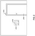
- FIG. 2shows a door sensor 214 (e.g. limit switch) that can detects the opening/closing of door 216 .
- FIG. 1depicts an illustrative security system 10 that includes a central controller 12 and a number of sensors/devices 14 a - 14 d .
- the sensor/devices 14 a - 14 dmay be configured to detect threats
- a control panel 210that includes the central controller 12 or is operatively connected to the central controller 12 .
- Other suitable security sensor/devices 14 a - 14 dmay include fire, smoke, carbon monoxide and/or natural gas detectors, to name a few. Still others suitable security system sensor/devices 14 a - 14 d may include motion sensors that detect motion of intruders in the secured area 16 . In some cases, one or more of the sensor/devices 14 a - 14 d may include a video camera. In some cases, the sensor/devices 14 a - 14 d may include a horn or alarm, a damper actuator controller (e.g.
- the sensor/devices 14 a - 14 dmay be any type of sensor or device suitable for operation in a building automation system.
- the central controller 12monitors the status of each of the sensor/devices 14 a - 14 d . Upon detecting a change of status in one of the sensor/devices 14 a - 14 d , the central controller may activate an alarm device, record and/or transmit live video from one of the sensor/devices 14 a - 14 d , operate an actuator, contact an off-site central monitoring station (not shown), and/or perform any other suitable action.
- Each of the sensor/devices 14 a - 14 dmay be operatively connected to the central controller 12 via a corresponding communications port 314 (see FIG. 3 ).
- the communications port 314may be wired and/or wireless.
- the communications port 314may include a wireless transceiver
- the central controller 12may include a compatible wireless transceiver.
- the wireless transceiversmay communicate using a standard and/or a proprietary communication protocol. Suitable standard wireless protocols may include, for example, cellular communication, ZigBee, Bluetooth, WiFi, IrDA, dedicated short range communication (DSRC), EnOcean, or any other suitable wireless protocols, as desired.
- each of the sensor/devices 14 a - 14 dPrior to operation of the security system 10 , each of the sensor/devices 14 a - 14 d must be enrolled with the central controller 12 so that the central controller 12 recognizes each of the sensor/devices 14 a - 14 d and places each of the sensor/devices 14 a - 14 d under the control of the central controller 12 .
- enrollmentis initiated by placing the central controller 12 into an enrollment mode. This can be accomplished by, for example, pressing an “enrollment” button on the central controller 12 , interacting with a user interface (e.g. control panel 210 , cell phone, tablet computer, etc.) that is operatively connected to the central controller 12 to place the central controller 12 into the enrollment mode, or in any other suitable manner.
- the central controllermay listen for new sensor/devices 14 a - 14 d for enrollment into the security system 10 .
- the installerthen may moves about the building and places each of the new devices into its enrollment mode. In some cases, this is accomplished by walking around the building and annunciating a predetermined enrollment trigger word or phrase.
- a microphone associated with a new sensor/device 14 a - 14 d that is in audible range of the installermay receive the spoken word or phrase of the installer as the installer walks near the new sensor/devices 14 a - 14 d .
- a controller of the new sensor/device 14 a - 14 dmay then determine if the received spoken word or phrase corresponds to the predetermined enrollment trigger word or phrase. If so, the controller of the new sensor/device 14 a - 14 d may enter its enrollment mode.
- the controller 312 of the new sensor/device 14 a - 14 dmay transmit a new device message to the central controller 12 , which may include a unique sensor/device identifier such as a MAC address or the like.
- the new device messagemay be received by the central controller 12 .
- the central controller 12may enroll the new sensor/device 14 a - 14 d into the security system 10 . This may include, for example, assigning a security system address to the new sensor/device and transmitting the assigned security system address to the new sensor/device 14 a - 14 d .
- the new sensor/device 14 a - 14 dmay provide an enrollment acknowledgment to the installer, such as a beep, a flash or the like.
- each of the new sensor/devices 14 a - 14 dmay enter its enrollment mode in response to other trigger stimulus provided by the installer.
- the new sensor/devices 14 a - 14 dmay enter the enrollment mode in response to a predetermined pattern of audio tones, sometimes generated by a mobile device such as a smartphone, tablet computer, laptop computer and/or any other suitable device.
- the predetermined pattern of audio tonesmay include a plurality of audio tones spaced along in a predetermined time pattern, a plurality of audio tones of different amplitudes, a plurality of audio tones of different frequencies, a plurality of audio tones of different amplitudes, different frequencies and spaced along a predetermined time pattern, a predetermined song, and/or any other suitable audio trigger.
- the trigger stimulusmay be optical.
- a new sensor/devices 14 a - 14 dmay include a light sensor 318 , IR sensor (e.g. passive infrared based motion sensor), 320 or any other suitable optical sensor.
- the trigger stimulusmay include a predetermined pattern of optical pulses.
- the predetermined pattern of optical pulsesmay include a plurality of optical pulses spaced along in a predetermined time pattern, a plurality of optical pulses of different amplitudes, a plurality of optical pulses of different frequencies, a plurality of optical pulses of different amplitudes, different frequencies and spaced along in a predetermined time pattern, and/or any other suitable optical trigger.
- the new sensor/devices 14 a - 14 dmay be enrolled in a particular order such that the central controller 12 associates each new sensor/devices 14 a - 14 d with a location in which it is installed.
- a voice commandcan be recognized by each new sensor/devices 14 a - 14 d that also names or identifies the particular new sensor/devices 14 a - 14 d .
- the installermay say the phrase “Begin sensor enrollment, front door.”
- the first part of the phrase(“begin sensor enrollment”) may be the predetermined enrollment trigger word or phrase to begin the enrollment process, while the second part of the phrase (“front door”) may be the assigned name of the new sensor/devices 14 a - 14 d.
- FIG. 3is a block diagram of an illustrative security system sensor 310 , which may correspond to one of sensor/devices 14 a - 14 d of FIG. 1 .
- Illustrative sensor 310includes a controller 312 , a communication port 314 and a trigger stimulus sensor.
- the trigger stimulus sensormay be any sensor that is suitable for detecting a predetermined trigger stimulus.
- the trigger stimulus sensormay include a microphone 316 , a light sensor 318 , and/or an IR sensor 320 as shown.
- the communications port 314may be a wired and/or a wireless communication port. In either case, the communications port 314 is configured to operatively communicate, either directly or indirectly, with a central controller such as central controller 12 of FIG. 1 .
- the communications port 314may include a wireless transceiver that is compatible with the wireless transceiver of a central controller 12 .
- the wireless transceiversmay communicate using a standard and/or a proprietary communication protocol. Suitable standard wireless protocols may include, for example, cellular communication, ZigBee, Bluetooth, WiFi, IrDA, dedicated short range communication (DSRC), EnOcean, or any other suitable wireless protocols, as desired.
- the controller 312is configured to receive a trigger stimulus from a trigger stimulus sensor. For example, when the sensor 310 includes the microphone 316 as a trigger stimulus sensor, the controller may receive an audio signal from the microphone 316 . For example, the microphone 316 may pick up a spoken word or phrase of an installer as the installer walks near the sensor 310 . The controller 312 may process the received audio signal and determine if the received spoken word or phrase corresponds to a predetermined enrollment trigger word or phrase. The predetermined enrollment trigger word or phrase, and/or a predetermined audio signal template that corresponds to the predetermined enrollment trigger word or phrase, may be stored in a memory 322 of the controller 312 .
- determine if the received spoken word or phrase corresponds to the predetermined enrollment trigger word or phrasemay be aided by a voice recognition engine 324 .
- the voice recognition engine 324may use natural language processing to recognize spoken words.
- voice recognition engine 324may use voice biometrics to help reduce interference and to reduce false triggers during the enrollment process.
- An example predetermined enrollment trigger word or phrasemay be “Begin sensor enrollment”.
- the installermay enter a custom predetermined enrollment trigger word or phrase by entering a programming mode of the sensor 310 .
- the controller 312may deactivate the voice recognition engine 324 so that the controller 312 does not consume power determining if subsequent received spoken words or phrases corresponds to the predetermined enrollment trigger word or phrase, but this is not required.
- the voice recognition engine 324may remain active after a successful enrollment, so that other audible commands can be recognized and executed, such as a system check command (see FIG. 6 ).
- the predetermined enrollment trigger word or phrase that is used to initiate the enrollment process of the sensor 310may also be used to name or identify the sensor 310 in the security system.
- the installermay say the phrase “Begin sensor enrollment, front door.”
- the first part of the phrase (“begin sensor enrollment”)may be the verbal command to begin the enrollment process, while the second part of the phrase (“front door”) may be the assigned name of the sensor 310 .
- the voice recognition engine 324 of the controller 312may parse the predetermined enrollment trigger word or phrase to separately identify the first and second part of the phrase.
- the assigned name of the sensor 310may be provided as a separate verbal command, with a different prefix like “Name Sensor, Front Door”.
- the prefix “Name Sensor”may be a recognizable trigger phrase, which is immediately followed by the desired name of the sensor 310 .
- the sensor namemay be communicated to the central controller 12 via the communications port 314 of sensor 310 , and the central controller 12 may associate the sensor name with the sensor 310 as the sensor 310 is enrolled.
- the sensor namemay be displayed on a control panel, such as control panel 210 , when the sensor 310 is triggered during subsequent operation of the security system 10 .
- the sensor 310may include one or more additional sensors 330 a - 3300 b beyond the trigger sensor(s) 316 , 318 , 320 .
- additional sensors 330 a - 330 bmay include a motion sensor, a video camera, a temperature sensor, a smoke sensor, a gas sensor, and/or any other sensor suitable for sensing one or more conditions within the secured area 16 .
- such additional sensors 330 a - 3300 bmay not be needed or desired.
- one or more of the trigger sensor(s) 316 , 318 , 320may function as one or more of the sensors for sensing one or more conditions within the secured area 16 .
- the microphone 316may be used during enrollment of the sensor 310 to pick up an audible trigger stimulus as the installer walks near the sensor 310 . However, after enrollment of the sensor 310 , the microphone 316 may be used to detect glass breakage in the secured area 16 , and in response to a detected glass breakage event, the controller 312 of the sensor 310 may communicate a glass breakage event to the central controller 12 .
- the IR sensor 320may be used during enrollment of the sensor 310 to detect an optical trigger stimulus. However, after enrollment of the sensor 310 , the IR sensor 320 may be used to detect motion in the secured area 16 , and in response to a detected motion event, the controller 312 of the sensor 310 may communicate a motion event to the central controller 12 . These are just some examples.
- the senor 310may include an actuator 332 .
- the actuatormay be, for example, a horn, a damper actuator, a valve actuator, garage door actuator, and/or any other suitable actuator.
- the controller 312may be configured to actuate actuator 332 , such as close a damper in response to a smoke event detected by a smoke sensor.
- the central controller 12may monitor the status of each of the sensor/devices 14 a - 14 d . Upon detecting a change of status of one of the sensor/devices 14 a - 14 d , the central controller 12 may activate an alarm device, record and/or transmit live video from one of the sensor/devices 14 a - 14 d , operate an actuator, contact an off-site central monitoring station (not shown), and/or perform any other suitable action.
- the installermay install a control panel 210 and one or more sensor/devices 214 , as shown in FIG. 2 .
- the control panel 210may be mounted near a commonly used entry/exit point, such as a door 216 .
- the control panel 210may include a display 212 , and may also accept inputs from the user. It is contemplated that the control panel 210 may include the central controller 12 or may be operatively connected to the central controller 12 .
- the illustrative security systemmay include a plurality of sensor/devices configured to monitor a state of the secured area 16 .
- a limit-switch 214is placed adjacent to the door 216 to detect the opening of said door 216 . This is just one example sensor.
- the systemmay include any number of sensors and in any configuration desired.
- the installermay use the user interface 212 of the control panel 210 to place the central controller 12 into an enrollment mode.
- the installer 218may walk around the premises saying out loud the predetermined enrollment trigger word or phrase (e.g. a spoken verbal command). As shown in FIG. 4 , the installer may walk around saying out loud the predetermined enrollment trigger word or phrase to each sensor/devices 214 a - 214 d , which causes each of the sensor/devices 214 a - 214 d to enter the enrollment mode as they pick up the audible enrollment trigger word or phrase.
- the installermay walk to each sensor/devices 214 a - 214 d location prior to speaking the predetermined enrollment trigger word or phrase.
- the distance the installer must stand from the sensor/devices 214 a - 214 dmay be determined by the sensitivity of the microphone/sensors 214 a - 214 d .
- an installermay need to stand within a few feet or within a few yards of a sensor for the spoken verbal command to be properly picked up and recognized by the corresponding sensor.
- the corresponding sensor/device 214 a - 214 dmay enter its enrollment mode and initiate a wireless communication 220 with the central controller 12 to enroll or register the corresponding sensor/device 214 a - 214 d with the central controller 12 .
- the security system 10may be functional and ready for service.
- the central controller 12may be placed in a checkout mode after all of the sensor/devices 214 a - 214 d are enrolled.
- the installer 218may walk around the premises saying out loud a predetermined checkout trigger word or phrase to trip each of the sensor/devices 214 a - 214 d .
- the installerOnce the installer has verified that each of the sensor/devices 214 a - 214 d can be tripped and the central controller 12 recognize the trip events, the installer can feel comfortable that each of the sensor/devices 214 a - 214 d has been properly enrolled and is functioning properly. The installer may then exit the enrollment and/or checkout mode.
- FIG. 5is a flow chart of an illustrative method for installing a building automation system such as security system in a building.
- the methodis generally shown at 500 , and begins by installing a building automation system that includes a central controller and one or more system sensors as shown at 510 . Once installed, the central controller is placed into an enrollment mode, as shown at 512 . Then, the installer may walk around the building uttering a predetermined audible enrollment trigger word or phrase. One of the system sensors may receive the uttered audible enrollment trigger word or phrase as an audio signal, as shown at 514 . The system sensor may then determine if the received audio signal matches a predetermined audio signal template, as shown at 516 .
- the predetermined audio signal templatemay correspond to the predetermined enrollment trigger word or phrase discussed above.
- controlis passed back to 514 , wherein the system sensor may continue to receive audio signals. If, however, the system sensor determines that the received audio signal does match the predetermined audio signal template, control is passed to 520 and the system sensor enters its enrollment mode. In the enrollment mode, the system sensor may communicate with the central controller of the building automation system, and receive a building automation system address that may then be stored in a memory of the system sensor. The building automation system address may be used during subsequent communication between the system sensor and the central controller. This may be continued until all of the system sensors have enrolled in the building automation system.
- FIG. 6is a flow chart of an illustrative method for initiate checkout mode in a building automation system such as security system in a building.
- the methodis generally shown at 600 .
- the central controllermay be placed into a checkout mode, as shown at 612 .
- the installermay walk around the building uttering a predetermined audible checkout trigger word or phrase.
- One of the system sensorsmay receive the uttered audible checkout trigger word or phrase as an audio signal, as shown at 614 .
- the system sensormay then determine if the received audio signal matches a predetermined audio signal template, as shown at 616 .
- the predetermined audio signal templatemay correspond to the predetermined checkout trigger word or phrase discussed above.
- controlis passed back to 614 , wherein the system sensor may continue to receive audio signals. If, however, the system sensor determines that the received audio signal does match the predetermined audio signal template, control is passed to 620 and the system sensor performs a system check.
- the system checkmay include sending a trigger event (e.g. an alarm event) to the central controller, which may then be confirmed by an audio beep, a flash or some other feedback if desired. This may be continued until all of the system sensors have performed a system check.
- a trigger evente.g. an alarm event
Landscapes
- Engineering & Computer Science (AREA)
- Physics & Mathematics (AREA)
- General Physics & Mathematics (AREA)
- Computational Linguistics (AREA)
- Health & Medical Sciences (AREA)
- Audiology, Speech & Language Pathology (AREA)
- Human Computer Interaction (AREA)
- Acoustics & Sound (AREA)
- Multimedia (AREA)
- Computer Networks & Wireless Communication (AREA)
- Signal Processing (AREA)
- Business, Economics & Management (AREA)
- Emergency Management (AREA)
- General Engineering & Computer Science (AREA)
- Automation & Control Theory (AREA)
- Alarm Systems (AREA)
Abstract
Description
Claims (10)
Priority Applications (4)
| Application Number | Priority Date | Filing Date | Title |
|---|---|---|---|
| US14/987,477US10642233B2 (en) | 2016-01-04 | 2016-01-04 | Device enrollment in a building automation system aided by audio input |
| EP16204901.9AEP3193329B1 (en) | 2016-01-04 | 2016-12-16 | Device enrollment in a building automation system aided by audio input |
| CA2952364ACA2952364A1 (en) | 2016-01-04 | 2016-12-19 | Device enrollment in a building automation system aided by audio input |
| CN201710001096.7ACN107025907B (en) | 2016-01-04 | 2017-01-03 | Device registration in a building automation system by means of audio input |
Applications Claiming Priority (1)
| Application Number | Priority Date | Filing Date | Title |
|---|---|---|---|
| US14/987,477US10642233B2 (en) | 2016-01-04 | 2016-01-04 | Device enrollment in a building automation system aided by audio input |
Publications (2)
| Publication Number | Publication Date |
|---|---|
| US20170192399A1 US20170192399A1 (en) | 2017-07-06 |
| US10642233B2true US10642233B2 (en) | 2020-05-05 |
Family
ID=57994998
Family Applications (1)
| Application Number | Title | Priority Date | Filing Date |
|---|---|---|---|
| US14/987,477Active2037-03-12US10642233B2 (en) | 2016-01-04 | 2016-01-04 | Device enrollment in a building automation system aided by audio input |
Country Status (4)
| Country | Link |
|---|---|
| US (1) | US10642233B2 (en) |
| EP (1) | EP3193329B1 (en) |
| CN (1) | CN107025907B (en) |
| CA (1) | CA2952364A1 (en) |
Cited By (1)
| Publication number | Priority date | Publication date | Assignee | Title |
|---|---|---|---|---|
| US11756531B1 (en) | 2020-12-18 | 2023-09-12 | Vivint, Inc. | Techniques for audio detection at a control system |
Families Citing this family (16)
| Publication number | Priority date | Publication date | Assignee | Title |
|---|---|---|---|---|
| DE102016201883A1 (en)* | 2016-02-09 | 2017-08-10 | Siemens Schweiz Ag | Method and arrangement for commissioning a building automation system |
| US10353480B2 (en)* | 2017-04-17 | 2019-07-16 | Essential Products, Inc. | Connecting assistant device to devices |
| US10176807B2 (en) | 2017-04-17 | 2019-01-08 | Essential Products, Inc. | Voice setup instructions |
| US10355931B2 (en) | 2017-04-17 | 2019-07-16 | Essential Products, Inc. | Troubleshooting voice-enabled home setup |
| US11636870B2 (en) | 2020-08-20 | 2023-04-25 | Denso International America, Inc. | Smoking cessation systems and methods |
| US11760170B2 (en) | 2020-08-20 | 2023-09-19 | Denso International America, Inc. | Olfaction sensor preservation systems and methods |
| US12017506B2 (en) | 2020-08-20 | 2024-06-25 | Denso International America, Inc. | Passenger cabin air control systems and methods |
| US11828210B2 (en) | 2020-08-20 | 2023-11-28 | Denso International America, Inc. | Diagnostic systems and methods of vehicles using olfaction |
| US12377711B2 (en) | 2020-08-20 | 2025-08-05 | Denso International America, Inc. | Vehicle feature control systems and methods based on smoking |
| US11881093B2 (en) | 2020-08-20 | 2024-01-23 | Denso International America, Inc. | Systems and methods for identifying smoking in vehicles |
| US12251991B2 (en) | 2020-08-20 | 2025-03-18 | Denso International America, Inc. | Humidity control for olfaction sensors |
| US11932080B2 (en) | 2020-08-20 | 2024-03-19 | Denso International America, Inc. | Diagnostic and recirculation control systems and methods |
| US12269315B2 (en) | 2020-08-20 | 2025-04-08 | Denso International America, Inc. | Systems and methods for measuring and managing odor brought into rental vehicles |
| US11813926B2 (en) | 2020-08-20 | 2023-11-14 | Denso International America, Inc. | Binding agent and olfaction sensor |
| US11760169B2 (en) | 2020-08-20 | 2023-09-19 | Denso International America, Inc. | Particulate control systems and methods for olfaction sensors |
| US12354591B2 (en)* | 2022-12-23 | 2025-07-08 | The Adt Security Corporation | Voice activated premises device enrollment in a security system |
Citations (33)
| Publication number | Priority date | Publication date | Assignee | Title |
|---|---|---|---|---|
| US5481714A (en) | 1993-10-18 | 1996-01-02 | International Business Machines Corporation | Method and system for installing an operating system on a data processing system with abort capability and voice input feature |
| WO2000021053A1 (en) | 1998-10-06 | 2000-04-13 | Slc Technologies, Inc. | Wireless home fire and security alarm system |
| US6477493B1 (en) | 1999-07-15 | 2002-11-05 | International Business Machines Corporation | Off site voice enrollment on a transcription device for speech recognition |
| US20040215750A1 (en) | 2003-04-28 | 2004-10-28 | Stilp Louis A. | Configuration program for a security system |
| WO2006033760A2 (en) | 2004-09-20 | 2006-03-30 | Honeywell International, Inc. | Network communication for a security system |
| US7042349B2 (en) | 2002-08-30 | 2006-05-09 | General Electric Company | Testing and installing sensors in a security system |
| US7113090B1 (en) | 2001-04-24 | 2006-09-26 | Alarm.Com Incorporated | System and method for connecting security systems to a wireless device |
| US7119658B2 (en) | 2003-02-03 | 2006-10-10 | Ingrid, Inc. | Device enrollment in a security system |
| US20060282649A1 (en)* | 2005-06-10 | 2006-12-14 | Malamud Mark A | Device pairing via voice commands |
| US7183907B2 (en) | 2004-10-20 | 2007-02-27 | Honeywell International, Inc. | Central station monitoring with real-time status and control |
| US20070247301A1 (en)* | 2006-04-20 | 2007-10-25 | Browne Michael A | Voice protector security alarm system |
| US20080072314A1 (en) | 2006-09-15 | 2008-03-20 | Tyco Safety Products Canada Ltd. | Method and apparatus for automated activation of a security system |
| US7634504B2 (en) | 2003-12-02 | 2009-12-15 | Honeywell International Inc. | Natural language installer setup for controller |
| US20110260832A1 (en)* | 2010-04-27 | 2011-10-27 | Joe Ross | Secure voice biometric enrollment and voice alert delivery system |
| US20120116748A1 (en)* | 2010-11-08 | 2012-05-10 | Sling Media Pvt Ltd | Voice Recognition and Feedback System |
| US20130035774A1 (en) | 2011-08-04 | 2013-02-07 | 2Gig Technologies, Inc. | System automation via an alarm system |
| US20130077797A1 (en)* | 2009-07-29 | 2013-03-28 | Innovalarm Corporation | Signal processing system and methods for reliably detecting audible alarms |
| WO2014004911A2 (en) | 2012-06-27 | 2014-01-03 | Icontrol Networks, Inc. | Control system user interface |
| US20140153281A1 (en) | 2012-12-04 | 2014-06-05 | Beijing Boe Chatani Electronics Co., Ltd. | Backlight unit and display device |
| US20140195233A1 (en)* | 2013-01-08 | 2014-07-10 | Spansion Llc | Distributed Speech Recognition System |
| US20140266687A1 (en) | 2013-03-12 | 2014-09-18 | Digital Monitoring Products, Inc. | Wireless security sensor registration |
| US8918219B2 (en) | 2010-11-19 | 2014-12-23 | Google Inc. | User friendly interface for control unit |
| US8976937B2 (en) | 2008-06-27 | 2015-03-10 | Adt Us Holding, Inc. | Method and apparatus for communication between a security system and a monitoring center |
| US20150077553A1 (en) | 2005-03-16 | 2015-03-19 | Paul J. Dawes | Controlling data routing in integrated security systems |
| US9043210B1 (en)* | 2012-10-02 | 2015-05-26 | Voice Security Systems, Inc. | Biometric voice command and control switching device and method of use |
| US20150187354A1 (en)* | 2012-08-20 | 2015-07-02 | Lg Innotek Co., Ltd. | Voice recognition apparatus and method of recognizing voice |
| US20150279134A1 (en)* | 2014-03-31 | 2015-10-01 | Vivint, Inc. | Mobile device based authentication |
| US20150276254A1 (en) | 2013-08-21 | 2015-10-01 | Honeywell International Inc. | User interaction with building controller device using a remote server and a duplex connection |
| US20150324179A1 (en)* | 2014-05-07 | 2015-11-12 | Vivint, Inc. | Voice control component installation |
| US20160134632A1 (en)* | 2014-11-12 | 2016-05-12 | Smartlabs, Inc. | Secure installation of network devices using beaconing systems and methods |
| US20160360526A1 (en)* | 2015-06-05 | 2016-12-08 | Apple Inc. | Simultaneous wireless connections with improved efficiency |
| US20170019362A1 (en)* | 2015-07-17 | 2017-01-19 | Motorola Mobility Llc | Voice Controlled Multimedia Content Creation |
| US20180367944A1 (en)* | 2015-06-25 | 2018-12-20 | Lg Electronics Inc. | Watch type mobile terminal and operation method thereof |
Family Cites Families (2)
| Publication number | Priority date | Publication date | Assignee | Title |
|---|---|---|---|---|
| US10505751B2 (en)* | 2011-08-25 | 2019-12-10 | Siemens Industry, Inc. | Synergistic interface system for a building network |
| US10089976B2 (en)* | 2013-10-14 | 2018-10-02 | Honeywell International Inc. | Building automation systems with voice control |
- 2016
- 2016-01-04USUS14/987,477patent/US10642233B2/enactiveActive
- 2016-12-16EPEP16204901.9Apatent/EP3193329B1/enactiveActive
- 2016-12-19CACA2952364Apatent/CA2952364A1/ennot_activeAbandoned
- 2017
- 2017-01-03CNCN201710001096.7Apatent/CN107025907B/enactiveActive
Patent Citations (36)
| Publication number | Priority date | Publication date | Assignee | Title |
|---|---|---|---|---|
| US5481714A (en) | 1993-10-18 | 1996-01-02 | International Business Machines Corporation | Method and system for installing an operating system on a data processing system with abort capability and voice input feature |
| WO2000021053A1 (en) | 1998-10-06 | 2000-04-13 | Slc Technologies, Inc. | Wireless home fire and security alarm system |
| US6624750B1 (en) | 1998-10-06 | 2003-09-23 | Interlogix, Inc. | Wireless home fire and security alarm system |
| US6477493B1 (en) | 1999-07-15 | 2002-11-05 | International Business Machines Corporation | Off site voice enrollment on a transcription device for speech recognition |
| US7113090B1 (en) | 2001-04-24 | 2006-09-26 | Alarm.Com Incorporated | System and method for connecting security systems to a wireless device |
| US7042349B2 (en) | 2002-08-30 | 2006-05-09 | General Electric Company | Testing and installing sensors in a security system |
| US7119658B2 (en) | 2003-02-03 | 2006-10-10 | Ingrid, Inc. | Device enrollment in a security system |
| US20040215750A1 (en) | 2003-04-28 | 2004-10-28 | Stilp Louis A. | Configuration program for a security system |
| US7634504B2 (en) | 2003-12-02 | 2009-12-15 | Honeywell International Inc. | Natural language installer setup for controller |
| WO2006033760A2 (en) | 2004-09-20 | 2006-03-30 | Honeywell International, Inc. | Network communication for a security system |
| US7675402B2 (en) | 2004-09-20 | 2010-03-09 | Honeywell International Inc. | Network communication for a security system |
| US7183907B2 (en) | 2004-10-20 | 2007-02-27 | Honeywell International, Inc. | Central station monitoring with real-time status and control |
| US20150077553A1 (en) | 2005-03-16 | 2015-03-19 | Paul J. Dawes | Controlling data routing in integrated security systems |
| US20060282649A1 (en)* | 2005-06-10 | 2006-12-14 | Malamud Mark A | Device pairing via voice commands |
| US8699944B2 (en)* | 2005-06-10 | 2014-04-15 | The Invention Science Fund I, Llc | Device pairing using device generated sound |
| US20070247301A1 (en)* | 2006-04-20 | 2007-10-25 | Browne Michael A | Voice protector security alarm system |
| US20080072314A1 (en) | 2006-09-15 | 2008-03-20 | Tyco Safety Products Canada Ltd. | Method and apparatus for automated activation of a security system |
| US8976937B2 (en) | 2008-06-27 | 2015-03-10 | Adt Us Holding, Inc. | Method and apparatus for communication between a security system and a monitoring center |
| US20130077797A1 (en)* | 2009-07-29 | 2013-03-28 | Innovalarm Corporation | Signal processing system and methods for reliably detecting audible alarms |
| US20110260832A1 (en)* | 2010-04-27 | 2011-10-27 | Joe Ross | Secure voice biometric enrollment and voice alert delivery system |
| US20120116748A1 (en)* | 2010-11-08 | 2012-05-10 | Sling Media Pvt Ltd | Voice Recognition and Feedback System |
| US8918219B2 (en) | 2010-11-19 | 2014-12-23 | Google Inc. | User friendly interface for control unit |
| US20130035774A1 (en) | 2011-08-04 | 2013-02-07 | 2Gig Technologies, Inc. | System automation via an alarm system |
| WO2014004911A2 (en) | 2012-06-27 | 2014-01-03 | Icontrol Networks, Inc. | Control system user interface |
| US20150187354A1 (en)* | 2012-08-20 | 2015-07-02 | Lg Innotek Co., Ltd. | Voice recognition apparatus and method of recognizing voice |
| US9043210B1 (en)* | 2012-10-02 | 2015-05-26 | Voice Security Systems, Inc. | Biometric voice command and control switching device and method of use |
| US20140153281A1 (en) | 2012-12-04 | 2014-06-05 | Beijing Boe Chatani Electronics Co., Ltd. | Backlight unit and display device |
| US20140195233A1 (en)* | 2013-01-08 | 2014-07-10 | Spansion Llc | Distributed Speech Recognition System |
| US20140266687A1 (en) | 2013-03-12 | 2014-09-18 | Digital Monitoring Products, Inc. | Wireless security sensor registration |
| US20150276254A1 (en) | 2013-08-21 | 2015-10-01 | Honeywell International Inc. | User interaction with building controller device using a remote server and a duplex connection |
| US20150279134A1 (en)* | 2014-03-31 | 2015-10-01 | Vivint, Inc. | Mobile device based authentication |
| US20150324179A1 (en)* | 2014-05-07 | 2015-11-12 | Vivint, Inc. | Voice control component installation |
| US20160134632A1 (en)* | 2014-11-12 | 2016-05-12 | Smartlabs, Inc. | Secure installation of network devices using beaconing systems and methods |
| US20160360526A1 (en)* | 2015-06-05 | 2016-12-08 | Apple Inc. | Simultaneous wireless connections with improved efficiency |
| US20180367944A1 (en)* | 2015-06-25 | 2018-12-20 | Lg Electronics Inc. | Watch type mobile terminal and operation method thereof |
| US20170019362A1 (en)* | 2015-07-17 | 2017-01-19 | Motorola Mobility Llc | Voice Controlled Multimedia Content Creation |
Non-Patent Citations (2)
| Title |
|---|
| 2 gig Technologies, "Go Control Wireless Security System, Installation & Programming Instructions," 52 pages, 2010. |
| The Extended European Search Report for EP Application Serial No. 16204901.9, dated Apr. 28, 2017. |
Cited By (1)
| Publication number | Priority date | Publication date | Assignee | Title |
|---|---|---|---|---|
| US11756531B1 (en) | 2020-12-18 | 2023-09-12 | Vivint, Inc. | Techniques for audio detection at a control system |
Also Published As
| Publication number | Publication date |
|---|---|
| US20170192399A1 (en) | 2017-07-06 |
| EP3193329B1 (en) | 2018-09-26 |
| CA2952364A1 (en) | 2017-07-04 |
| CN107025907B (en) | 2023-10-13 |
| EP3193329A1 (en) | 2017-07-19 |
| CN107025907A (en) | 2017-08-08 |
Similar Documents
| Publication | Publication Date | Title |
|---|---|---|
| US10642233B2 (en) | Device enrollment in a building automation system aided by audio input | |
| US11346143B1 (en) | Garage door authentication and automation | |
| US7106193B2 (en) | Integrated alarm detection and verification device | |
| US8730029B2 (en) | Tablet computer as user interface of security system | |
| WO2020096969A1 (en) | System and apparatus for a home security system | |
| US10455271B1 (en) | Voice control component installation | |
| US20240420563A1 (en) | Security system automatic bypass reset | |
| US9734697B1 (en) | Automatic notify mode for security system | |
| US20190392691A1 (en) | Entry security system and method | |
| US20200312121A1 (en) | Alarm system supervisory by zone | |
| KR20190024254A (en) | Doorbell | |
| US11961349B1 (en) | Biometric authentication for security sensor bypass | |
| KR20110012048A (en) | Integrated control system and its monitoring method | |
| US10197983B2 (en) | Fast replacement Z-wave device in home automation | |
| US10825332B2 (en) | Home smart listening device linking to transport vehicle | |
| US20210158030A1 (en) | Accessibility features for monitoring systems | |
| US10726689B1 (en) | Systems and methods for leveraging internet-of-things devices in security systems | |
| CA2868172C (en) | Ambient condition detector with processing of incoming audible commands followed by speech recognition | |
| EP4092643B1 (en) | A security monitoring system | |
| US20250037522A1 (en) | Multi-factor authentication for premises monitoring systems | |
| EP4552930A1 (en) | Commanding an action of a vehicle | |
| US20250218233A1 (en) | Multi-factor authentication for premises monitoring systems | |
| WO2025029490A1 (en) | Multi-factor authentication for premises monitoring systems |
Legal Events
| Date | Code | Title | Description |
|---|---|---|---|
| AS | Assignment | Owner name:HONEYWELL INTERNATIONAL INC, NEW JERSEY Free format text:ASSIGNMENT OF ASSIGNORS INTEREST;ASSIGNORS:RAMAKRISHNAPPA, HARISH M;ASWATH, RAVIKUMAR VEMAGAL;REEL/FRAME:037508/0603 Effective date:20151201 | |
| AS | Assignment | Owner name:JPMORGAN CHASE BANK, N.A., AS ADMINISTRATIVE AGENT, NEW YORK Free format text:SECURITY INTEREST;ASSIGNOR:ADEMCO INC.;REEL/FRAME:047337/0577 Effective date:20181025 Owner name:JPMORGAN CHASE BANK, N.A., AS ADMINISTRATIVE AGENT Free format text:SECURITY INTEREST;ASSIGNOR:ADEMCO INC.;REEL/FRAME:047337/0577 Effective date:20181025 | |
| AS | Assignment | Owner name:ADEMCO INC., MINNESOTA Free format text:ASSIGNMENT OF ASSIGNORS INTEREST;ASSIGNOR:HONEYWELL INTERNATIONAL INC.;REEL/FRAME:047909/0425 Effective date:20181029 | |
| STPP | Information on status: patent application and granting procedure in general | Free format text:RESPONSE TO NON-FINAL OFFICE ACTION ENTERED AND FORWARDED TO EXAMINER | |
| STPP | Information on status: patent application and granting procedure in general | Free format text:FINAL REJECTION MAILED | |
| AS | Assignment | Owner name:ADEMCO INC., MINNESOTA Free format text:CORRECTIVE ASSIGNMENT TO CORRECT THE PREVIOUS RECORDING BY NULLIFICATION. THE INCORRECTLY RECORDED PATENT NUMBERS 8545483, 8612538 AND 6402691 PREVIOUSLY RECORDED AT REEL: 047909 FRAME: 0425. ASSIGNOR(S) HEREBY CONFIRMS THE ASSIGNMENT;ASSIGNOR:HONEYWELL INTERNATIONAL INC.;REEL/FRAME:050431/0053 Effective date:20190215 | |
| STPP | Information on status: patent application and granting procedure in general | Free format text:DOCKETED NEW CASE - READY FOR EXAMINATION | |
| STPP | Information on status: patent application and granting procedure in general | Free format text:NON FINAL ACTION MAILED | |
| STPP | Information on status: patent application and granting procedure in general | Free format text:RESPONSE TO NON-FINAL OFFICE ACTION ENTERED AND FORWARDED TO EXAMINER | |
| STPP | Information on status: patent application and granting procedure in general | Free format text:NOTICE OF ALLOWANCE MAILED -- APPLICATION RECEIVED IN OFFICE OF PUBLICATIONS | |
| STCF | Information on status: patent grant | Free format text:PATENTED CASE | |
| MAFP | Maintenance fee payment | Free format text:PAYMENT OF MAINTENANCE FEE, 4TH YEAR, LARGE ENTITY (ORIGINAL EVENT CODE: M1551); ENTITY STATUS OF PATENT OWNER: LARGE ENTITY Year of fee payment:4 | |
| AS | Assignment | Owner name:RESIDEO LLC, DELAWARE Free format text:CHANGE OF NAME;ASSIGNOR:ADEMCO INC.;REEL/FRAME:071546/0001 Effective date:20241227 |