US10641644B2 - System and method for estimating an amount of a blood component in a volume of fluid - Google Patents
System and method for estimating an amount of a blood component in a volume of fluidDownload PDFInfo
- Publication number
- US10641644B2 US10641644B2US15/389,365US201615389365AUS10641644B2US 10641644 B2US10641644 B2US 10641644B2US 201615389365 AUS201615389365 AUS 201615389365AUS 10641644 B2US10641644 B2US 10641644B2
- Authority
- US
- United States
- Prior art keywords
- canister
- fluid
- image
- recess
- window
- Prior art date
- Legal status (The legal status is an assumption and is not a legal conclusion. Google has not performed a legal analysis and makes no representation as to the accuracy of the status listed.)
- Active
Links
Images


Classifications
- G—PHYSICS
- G01—MEASURING; TESTING
- G01G—WEIGHING
- G01G17/00—Apparatus for or methods of weighing material of special form or property
- G01G17/04—Apparatus for or methods of weighing material of special form or property for weighing fluids, e.g. gases, pastes
- A61M1/0001—
- A61M1/0039—
- A—HUMAN NECESSITIES
- A61—MEDICAL OR VETERINARY SCIENCE; HYGIENE
- A61M—DEVICES FOR INTRODUCING MEDIA INTO, OR ONTO, THE BODY; DEVICES FOR TRANSDUCING BODY MEDIA OR FOR TAKING MEDIA FROM THE BODY; DEVICES FOR PRODUCING OR ENDING SLEEP OR STUPOR
- A61M1/00—Suction or pumping devices for medical purposes; Devices for carrying-off, for treatment of, or for carrying-over, body-liquids; Drainage systems
- A61M1/60—Containers for suction drainage, adapted to be used with an external suction source
- A—HUMAN NECESSITIES
- A61—MEDICAL OR VETERINARY SCIENCE; HYGIENE
- A61M—DEVICES FOR INTRODUCING MEDIA INTO, OR ONTO, THE BODY; DEVICES FOR TRANSDUCING BODY MEDIA OR FOR TAKING MEDIA FROM THE BODY; DEVICES FOR PRODUCING OR ENDING SLEEP OR STUPOR
- A61M1/00—Suction or pumping devices for medical purposes; Devices for carrying-off, for treatment of, or for carrying-over, body-liquids; Drainage systems
- A61M1/71—Suction drainage systems
- A61M1/76—Handpieces
- A—HUMAN NECESSITIES
- A61—MEDICAL OR VETERINARY SCIENCE; HYGIENE
- A61M—DEVICES FOR INTRODUCING MEDIA INTO, OR ONTO, THE BODY; DEVICES FOR TRANSDUCING BODY MEDIA OR FOR TAKING MEDIA FROM THE BODY; DEVICES FOR PRODUCING OR ENDING SLEEP OR STUPOR
- A61M5/00—Devices for bringing media into the body in a subcutaneous, intra-vascular or intramuscular way; Accessories therefor, e.g. filling or cleaning devices, arm-rests
- A61M5/14—Infusion devices, e.g. infusing by gravity; Blood infusion; Accessories therefor
- A61M5/168—Means for controlling media flow to the body or for metering media to the body, e.g. drip meters, counters ; Monitoring media flow to the body
- A61M5/16831—Monitoring, detecting, signalling or eliminating infusion flow anomalies
- A61M5/1684—Monitoring, detecting, signalling or eliminating infusion flow anomalies by detecting the amount of infusate remaining, e.g. signalling end of infusion
- A61M5/1685—Monitoring, detecting, signalling or eliminating infusion flow anomalies by detecting the amount of infusate remaining, e.g. signalling end of infusion by detection of position of a floating member
- G—PHYSICS
- G01—MEASURING; TESTING
- G01G—WEIGHING
- G01G21/00—Details of weighing apparatus
- G01G21/28—Frames, Housings
- G—PHYSICS
- G01—MEASURING; TESTING
- G01N—INVESTIGATING OR ANALYSING MATERIALS BY DETERMINING THEIR CHEMICAL OR PHYSICAL PROPERTIES
- G01N33/00—Investigating or analysing materials by specific methods not covered by groups G01N1/00 - G01N31/00
- G01N33/48—Biological material, e.g. blood, urine; Haemocytometers
- G01N33/483—Physical analysis of biological material
- G01N33/487—Physical analysis of biological material of liquid biological material
- G01N33/49—Blood
- G01N33/4925—Blood measuring blood gas content, e.g. O2, CO2, HCO3
- H—ELECTRICITY
- H04—ELECTRIC COMMUNICATION TECHNIQUE
- H04N—PICTORIAL COMMUNICATION, e.g. TELEVISION
- H04N23/00—Cameras or camera modules comprising electronic image sensors; Control thereof
- H04N23/50—Constructional details
- H04N23/54—Mounting of pick-up tubes, electronic image sensors, deviation or focusing coils
- H—ELECTRICITY
- H04—ELECTRIC COMMUNICATION TECHNIQUE
- H04N—PICTORIAL COMMUNICATION, e.g. TELEVISION
- H04N23/00—Cameras or camera modules comprising electronic image sensors; Control thereof
- H04N23/57—Mechanical or electrical details of cameras or camera modules specially adapted for being embedded in other devices
- H04N5/2253—
- H04N5/2257—
- A—HUMAN NECESSITIES
- A61—MEDICAL OR VETERINARY SCIENCE; HYGIENE
- A61M—DEVICES FOR INTRODUCING MEDIA INTO, OR ONTO, THE BODY; DEVICES FOR TRANSDUCING BODY MEDIA OR FOR TAKING MEDIA FROM THE BODY; DEVICES FOR PRODUCING OR ENDING SLEEP OR STUPOR
- A61M2205/00—General characteristics of the apparatus
- A61M2205/33—Controlling, regulating or measuring
- A61M2205/3306—Optical measuring means
- A—HUMAN NECESSITIES
- A61—MEDICAL OR VETERINARY SCIENCE; HYGIENE
- A61M—DEVICES FOR INTRODUCING MEDIA INTO, OR ONTO, THE BODY; DEVICES FOR TRANSDUCING BODY MEDIA OR FOR TAKING MEDIA FROM THE BODY; DEVICES FOR PRODUCING OR ENDING SLEEP OR STUPOR
- A61M2205/00—General characteristics of the apparatus
- A61M2205/33—Controlling, regulating or measuring
- A61M2205/3379—Masses, volumes, levels of fluids in reservoirs, flow rates
- A61M2205/3393—Masses, volumes, levels of fluids in reservoirs, flow rates by weighing the reservoir
- A—HUMAN NECESSITIES
- A61—MEDICAL OR VETERINARY SCIENCE; HYGIENE
- A61M—DEVICES FOR INTRODUCING MEDIA INTO, OR ONTO, THE BODY; DEVICES FOR TRANSDUCING BODY MEDIA OR FOR TAKING MEDIA FROM THE BODY; DEVICES FOR PRODUCING OR ENDING SLEEP OR STUPOR
- A61M2205/00—General characteristics of the apparatus
- A61M2205/35—Communication
- A61M2205/3576—Communication with non implanted data transmission devices, e.g. using external transmitter or receiver
- A61M2205/3592—Communication with non implanted data transmission devices, e.g. using external transmitter or receiver using telemetric means, e.g. radio or optical transmission
- A—HUMAN NECESSITIES
- A61—MEDICAL OR VETERINARY SCIENCE; HYGIENE
- A61M—DEVICES FOR INTRODUCING MEDIA INTO, OR ONTO, THE BODY; DEVICES FOR TRANSDUCING BODY MEDIA OR FOR TAKING MEDIA FROM THE BODY; DEVICES FOR PRODUCING OR ENDING SLEEP OR STUPOR
- A61M2205/00—General characteristics of the apparatus
- A61M2205/50—General characteristics of the apparatus with microprocessors or computers
- A—HUMAN NECESSITIES
- A61—MEDICAL OR VETERINARY SCIENCE; HYGIENE
- A61M—DEVICES FOR INTRODUCING MEDIA INTO, OR ONTO, THE BODY; DEVICES FOR TRANSDUCING BODY MEDIA OR FOR TAKING MEDIA FROM THE BODY; DEVICES FOR PRODUCING OR ENDING SLEEP OR STUPOR
- A61M2205/00—General characteristics of the apparatus
- A61M2205/70—General characteristics of the apparatus with testing or calibration facilities
- A—HUMAN NECESSITIES
- A61—MEDICAL OR VETERINARY SCIENCE; HYGIENE
- A61M—DEVICES FOR INTRODUCING MEDIA INTO, OR ONTO, THE BODY; DEVICES FOR TRANSDUCING BODY MEDIA OR FOR TAKING MEDIA FROM THE BODY; DEVICES FOR PRODUCING OR ENDING SLEEP OR STUPOR
- A61M2230/00—Measuring parameters of the user
- A61M2230/20—Blood composition characteristics
- A—HUMAN NECESSITIES
- A61—MEDICAL OR VETERINARY SCIENCE; HYGIENE
- A61M—DEVICES FOR INTRODUCING MEDIA INTO, OR ONTO, THE BODY; DEVICES FOR TRANSDUCING BODY MEDIA OR FOR TAKING MEDIA FROM THE BODY; DEVICES FOR PRODUCING OR ENDING SLEEP OR STUPOR
- A61M5/00—Devices for bringing media into the body in a subcutaneous, intra-vascular or intramuscular way; Accessories therefor, e.g. filling or cleaning devices, arm-rests
- A61M5/14—Infusion devices, e.g. infusing by gravity; Blood infusion; Accessories therefor
- A61M5/168—Means for controlling media flow to the body or for metering media to the body, e.g. drip meters, counters ; Monitoring media flow to the body
- A61M5/16886—Means for controlling media flow to the body or for metering media to the body, e.g. drip meters, counters ; Monitoring media flow to the body for measuring fluid flow rate, i.e. flowmeters
- A61M5/16895—Means for controlling media flow to the body or for metering media to the body, e.g. drip meters, counters ; Monitoring media flow to the body for measuring fluid flow rate, i.e. flowmeters by monitoring weight change, e.g. of infusion container
- G—PHYSICS
- G01—MEASURING; TESTING
- G01G—WEIGHING
- G01G19/00—Weighing apparatus or methods adapted for special purposes not provided for in the preceding groups
- G01G19/52—Weighing apparatus combined with other objects, e.g. furniture
Definitions
- This inventionrelates generally to the field of blood loss management and more specifically to a new and useful system and method for estimating an amount of a blood component in a volume of fluid in the field of blood loss management.
- a system for assessing a fluid canistercomprising a mounting structure with a canister recess and an imaging device recess, an inter recess wall between the canister recess and the imaging device recess, a scale coupled to the mounting structure and configured with at least one measurement element in communication with the canister recess, and a scale communication module configured to transmit weight information from the scale to a computing device.
- the measurement elementmay comprise a piezoelectric element.
- the imaging device recessmay comprise a data interface in wired communication with the communication module.
- the systemmay further comprise a first aperture located in the inter-recess wall. The first aperture may include a window and seal between the window and the inter-recess wall.
- the systemmay further comprise a second aperture located in the inter-recess wall.
- the inter-recess wallmay comprise a curved portion with a concave surface facing the canister recess.
- the inter-recess wallmay further comprise a flat portion facing the imaging device recess.
- the canister recessmay comprise a movable surface.
- the systemmay further comprise a fluid canister configured to removably reside in the canister recess, and wherein the reflective insert may be configured to reside inside the fluid canister.
- the systemmay further comprise a reflective insert configured to reside within the fluid canister.
- the inter-recess wallmay comprise a first aperture located at a vertical height corresponding to the reflective insert when placed at a bottom of the fluid canister when the fluid canister may be fully seated in the canister recess.
- the fluid canistermay have a frusto-conical shape.
- the inter-recess wallhas a vertical angle matching a frusto-conical angle of the fluid canister.
- the systemmay further comprise an imaging device configured to be removably inserted into the imaging device recess.
- the imaging devicemay be a computing device comprising an imaging assembly configured to acquire canister images from canister located in the canister recess and a processor configured to receive weight information from the communication module.
- the processormay be further configured to acquire a canister image with the imaging assembly upon detecting a weight change using the weight information.
- the computing devicemay further comprise a computing communication module configured to transmit the canister images and weight information from the computing device.
- the fluid canistermay comprise an inlet and an outlet, wherein the outlet may be configured to be coupled to a vacuum source.
- the computing devicemay be configured to acquire canister images at the same acquisition rate that the processor may be configured to acquire weight information.
- the acquisition ratemay be in the range of about one acquisition every 1 to 5 seconds.
- a method of assessing a fluid canistercomprising detecting the weight a fluid canister attached to a vacuum system, generating an image of the fluid canister, and determining a hemoglobin value of the fluid canister using the image.
- the imagingmay be initiated upon detecting a change in the weight of the fluid canister.
- the methodmay further comprise modifying the hemoglobin value using the weight.
- the methodmay further comprise draining the fluid canister, and setting a tare weight of the fluid canister after draining the fluid canister.
- a blood monitoring systemcomprising a canister, a mount, a weighing scale, an imaging system, and a processor, wherein the canister defines an internal volume and comprises a translucent section.
- the blood monitoring systemmay further comprise a reflective insert arranged within the internal volume and adjacent and offset from the translucent section.
- the mountmay be configured to engage an exterior surface of the canister.
- the mountmay define a first window configured to seal over the exterior surface of the canister proximal the translucent section.
- the mountmay further define a second window adjacent the first window and configured to seal over the exterior surface of the canister proximal the translucent section.
- the first windowmay be substantially optically isolated from the second window.
- the weighing scalemay be coupled to the mount and may be configured to output a signal corresponding to a weight of contents in the canister.
- the imaging systemmay comprise an optical emitter aligned with the first window and configured to illuminate the reflective insert through the translucent section of the canister.
- the imaging systemmay further comprise a camera aligned with the second window.
- the processormay be configured to transform an image captured by the camera into an estimated concentration of a blood component in a fluid within the canister and to estimate an amount of the blood component in the canister based on the estimated concentration of the blood component and an output of the weighing scale.
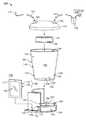
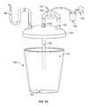
- FIG. 1is a schematic representation of a canister assessment system
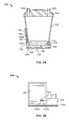
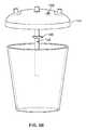
- FIGS. 2A and 2Bare schematic representations of one variation of a system described herein;
- FIG. 3is a schematic representation of a method for assessing a canister
- FIG. 4A to 4Care schematic examples of a fluid canister with an integrally formed reflective surface
- FIG. 5Ais an example of a fluid canister with a sump pickup
- FIGS. 5B and 5Care examples of fluid canisters with a sump pickup and integrated float sensor and fluid level sensor, respectively;
- FIG. 6Ais a side cross-sectional view of a fluid canister with a magnetic agitator
- FIG. 6Bis a superior schematic view of the reflective insert in FIG. 6A
- FIG. 6Cis a side cross-sectional view of another fluid canister with a magnetic agitator
- FIG. 6Dis a is superior schematic view of the reflective insert in FIG. 6C
- FIG. 6Eis a side cross-sectional view of another fluid canister with a mechanical agitator.
- the system 100includes a canister 102 configured to collect and hold fluid, an optical emitter 128 that illuminates fluid in the canister 102 , a camera 130 that captures images of illuminated fluid, and a processor 132 that transforms color values contained in images captured by the camera 130 into estimations of a quality of fluid contained in the canister 102 , such as a concentration of total hemoglobin, free hemoglobin, whole red blood cells, or whole blood, etc. in the fluid in the canister 102 .
- a quality of fluid contained in the canister 102such as a concentration of total hemoglobin, free hemoglobin, whole red blood cells, or whole blood, etc.
- the systemalso includes a weighing scale 106 , and the system 100 can generate an estimation of a mass or volume of one or more blood components in the canister by merging an output of the weighing scale 106 with a blood component concentration thus estimated from color values in an image of the canister 102 .
- an estimate of the total hemoglobin content of the fluid in the canistermay be calculated using the combination of the estimated concentration and volume of a blood component generated from the image and weight information from the scale, respectively.
- a system 100 for estimating an amount of a blood component in a volume of fluidincludes a canister 102 , a mount 104 , a weighing scale 106 , an imaging system 126 , and a processor 132 .
- the canister 102defines an internal volume 112 and a translucent section 114 or wall, and may include a reflective insert 116 arranged within the internal volume 112 and adjacent and offset from the translucent section 114 .
- the mount 104is configured to engage an exterior surface 118 of the canister 102 , and may comprise a first window 120 with a first seal 122 a/b configured to seal over the exterior surface 118 of the canister 102 proximal the translucent section 114 , and may further comprise a second window 124 adjacent the first window 120 and configured to seal over the exterior surface 118 of the canister 102 proximal the translucent section 114 , wherein the first window 120 is substantially optically isolated from the second window 124 , by the first seal 122 a/b .
- the weighing scale 106is coupled to the mount 104 and is configured to output a signal corresponding to a weight of contents in the canister 102 .
- the imaging system 126includes an optical emitter 128 aligned with the first window 120 and configured to illuminate the reflective insert 116 through the translucent section 114 of the canister 102 , and also includes a camera 130 aligned with the second window.
- the imaging system componentsmay be provided on a computing device 131 .
- the processor 132is in communication with the imaging system of the computing device 131 and is configured to transform an image captured by the camera 130 into an estimated concentration of a blood component in a fluid within the canister 102 and to estimate an amount or volume of the blood component in the canister 102 based on the estimated concentration of the blood component and an output of the weighing scale 106 .
- the processor 132may be located in a remote computing system or cloud-based system, but in other examples, the processor 132 may be located or incorporated into the computing device 131 .
- the scale 106may also be used to detect other activity relating to the canister 102 and/or the fluid in the canister 102 .
- removal of the canister 102may be detected so that the processor 132 can store the last or final concentration and volume information from the removed canister 102 and reset any counter(s) or register(s) for measuring any new canister.
- the system 100can be integrated into a surgical suction system within an operating room, surgical or procedure suite, emergency room, medical clinic, or other medical or health-related setting.
- the systemcan interface with a primary canister and a suction wand in a surgical suction system to intermittently accumulate fluid collected with the suction wand, to capture an image of this fluid, to transform this image into an estimation of a quality of the fluid, and to then release its contents into the primary canister.
- a vacuum pump 134 and regulator 136 coupled to a primary canister 138can draw vacuum on the primary canister 138 ; the primary canister 138 can be fluidly coupled to the (intermediate) canister 102 of the system 100 , and the suction wand 140 can be fluidly coupled to the (intermediate) canister 102 of the system 100 such that, when the vacuum pump 134 draws a vacuum on the primary canister 138 , vacuum is communicated to the suction wand 140 via the (intermediate) canister 102 of the system 100 .
- a nurse, anesthesiologist, surgeon, or other operatorcan thus manipulate the suction wand 140 to collect fluids from within and around a patient during a surgery and to dispense these fluids into the (intermediate) canister 102 .
- the system 100repeatedly captures and processes images of fluid in the canister 102 and samples the weighing scale 106 to generate updated fluid quality and quantity estimations throughout operations or procedures.
- the (intermediate) canister 102once the (intermediate) canister 102 is full, its contents can be dispensed into the primary canister 138 for holding; the (intermediate) canister 102 can then be refilled via the suction wand 140 and its contents analyzed optically and/or by weight.
- the system 100can therefore be implemented in conjunction with a surgical wand and/or a primary (suction) canister within a surgical or other medical, clinical, or hospital setting to collect and image discrete volumes of blood and other bodily fluids.
- Components in the system that contact hazardous wastee.g., blood, mucus, urine, etc.
- canister and the reflective insertcan be used during a single operation or surgery and then disposed of, and the mount, weighing scale, imaging system, and processor can installed on multiple canisters across multiple surgeries over time to optically analyze qualities of fluids captured in these one-time-use canisters.
- the suction systemmay be attached to other vacuum systems, such as a negative pressure wound therapy system or a chest tube system, or an indwelling surgical draining tube, for assessing the amount and/or type of fluid loss or accumulation at those anatomical sites.
- other vacuum systemssuch as a negative pressure wound therapy system or a chest tube system, or an indwelling surgical draining tube, for assessing the amount and/or type of fluid loss or accumulation at those anatomical sites.
- the intermediate canister 102defines an internal volume 112 and a translucent section 114 or sidewall; and may include a reflective insert 116 configured to be inserted or arranged within the internal volume 112 and adjacent and offset from the translucent section 114 .
- the canister 102defines a vessel configured to collect fluid over time, includes a translucent or transparent material through which the imaging system 126 can illuminate contents of the vessel and capture images of contents of the vessel, and may include a reflective insert 116 (or reflective surface) that reflects and spreads light output from the imaging system 126 across a local volume of fluid to be imaged.
- the reflective insert 116may cooperate with the wall 142 of the canister 102 to constrain a local volume of fluid in the canister 102 to a relatively shallow depth such that the imaging system 126 can capture color data through the full depth of this local volume of fluid (substantially) despite a concentration of red blood cells in the canister that may progressively block light transmission at greater depths.
- the reflective insert 116 and the canister 102may comprise recesses 195 and projections 197 configured to set the rotational orientation of the insert 116 and the canister 102 .
- the canisterhas a frusto-conical shape and is comprised of a substantially transparent polymer (e.g., polyethylene terephthalate, polymethyl methacrylate, polycarbonate, cellulose acetate butyrate) and may be configured to hold 3,000 milliliters of fluid.
- the canistermay have a capacity in the range of about 500 ml to 10,000 ml, or about 1,000 ml to about 5,000 ml, or about 1,000 ml to 3,000 ml.
- the reflective insertmay be comprised of any suitable material, for example, a polymer (e.g., white nylon, polycarbonate, polyethylene, polymethyl methacrylate) structure configured to sit in, or couple to, the bottom of the canister.
- the canistercan include an engagement feature in its base or in the wall of the vessel proximal its base and configured to retain the reflective insert.
- the canistermay comprise a polygonal shape, a cylindrical shape, or other shape, including one with at least one planar side surface or wall.
- the canister 400may include a column 402 within the internal volume 404 of the canister 400 and extending upwardly from the base 406 of the frusto-conical vessel, offset inwardly from the interior wall 408 of the frusto-conical vessel, and backed or covered with a reflective material 410 , or formed from a reflective material.
- the frusto-conical vessel and the column 402can define a unitary structure (e.g., a drawn or molded polymer structure) with the base 406 , and the column can thus function like the reflective insert to constrain a local volume of fluid in the canister to a shallow depth relative to the imaging system.
- the canister and the reflective insertcan define any other geometry or include any other suitable material.
- the columnmay comprise a cylindrical shape, or may comprise a polygonal cross-sectional shape with at least one planar surface, such as a rectangle or square.
- the canister 412 , 414may comprise a projection or outwardly facing interior wall 416 , 418 within internal volume 420 , 422 that is integrally formed with or attached to the sidewall 424 or lid 426 of the canister, 412 , 414 , respectively.
- FIG. 4Bcomprises a flanged arcuate wall 416 that is offset from the base 428 of the canister 412 and the sidewall 424 but attached at one or both edges 426 to the sidewall 424 .
- the offsetmay permit the fluid level in the canister to rise between the sidewall 424 and the arcuate wall 416 , while still permitting agitation of the base 428 of the canister 412 .
- the wall 428is attached to the underside of the lid 426 , and permits unimpeded fluid flow around the wall 428 as the internal volume 422 is filled, and also permits unimpeded agitation of the base 430 of the canister 414 .
- the system 100can also include a lid 144 configured to cover and/or seal an upper opening 146 in the canister 102 .
- the lid 144includes an inlet port 148 configured to couple to a suction wand 140 ; and an outlet port 150 configured to couple to a vacuum pump 134 (via an optional primary canister 138 ) using vacuum lines 152 , 154 .
- a vacuum pump 134via an optional primary canister 138
- the lid 144is also depicted with an optional sump pickup 156 extending from the lid 144 to the base 158 of the canister 102 and in fluid communication with the vacuum port 160 ; and a two-way valve 162 configured to selectively connect the outlet port 150 to an upper volume 152 of the canister 102 in a first position and to the vacuum port 160 of the sump pickup 156 in a second position.
- the lid 144can communicate vacuum from an external vacuum source 134 into the canister 102 just below lid 144 .
- the canistercan communicate vacuum to the suction wand 140 to draw fluid into the canister 102 .
- the lid 144communicates vacuum from the external source 134 to the sump pickup 156 such that fluid is drawn up the sump pickup 156 , through the vacuum port 160 in fluid communication with the sump pickup 156 , and into a remote fluid collector (e.g., to a primary canister 138 ).
- the valve 162can be manually actuated by a user on a switch 164 or button (or other mechanical mechanism on the valve 162 ) when the canister is sufficiently full of fluid in order to drain the contents of the canister into another container (e.g., a primary canister), or the system can automatically switch the valve between the first and second positions via a solenoid or other valve control mechanism, such as when the weighing scale 106 indicates that a threshold mass of fluid (corresponding to an approximate threshold volume of fluid in the canister based on an 160 estimated fluid density of ⁇ 1030 kg/m 3 ) is contained in the canister 102 or when an output state of a float sensor in the lid changes, thereby indicating that a preset fill level limit has been reached.
- a threshold mass of fluidcorresponding to an approximate threshold volume of fluid in the canister based on an 160 estimated fluid density of ⁇ 1030 kg/m 3
- the usermay also control the valve electronically via the processor or other user interface.
- the valve 162 in FIG. 5Ais depicted as separate from the lid 144 , in other variations, the valve, the vacuum port to the sump pickup, and the fluid line therebetween may be integrally formed or housed within the lid, such that only an inlet to be attached to a suction wand or catheter, and an outlet port from the integrated valve, are provided on the lid.
- a wired data interfacemay be provided on the lid, or a wireless communication module to the computer device may be provided.
- the fluid level sensormay comprise a float sensor mechanism 166 configured to travel up and down along the sump pickup 156 .
- the float sensor mechanism 166may be configured to close electrodes on the underside of the lid 144 upon reaching a designated fluid level, to provide a signal via a float signal interface 168 in communication with the processor to detect canister volume.
- the float sensor mechanismmay be a visual aid for the imaging system to detect the fluid level.
- the fluid level sensormay be comprise a series of fluid contact electrodes 170 as shown in FIG. 5C along the length of the sump pickup 156 .
- Different pairings of the electrodes 168may be checked via the float signal interface 168 in communication with the processor to determine the fluid level based upon the closed electrode loop formed by the fluid.
- the fluid level sensormay also be provided on a vertical structure separate from the sump pickup, including but not limited to the inner wall of the canister.
- the scale 106may also be used to detect other activity relating to the canister 102 For example, removal of the canister 102 may be detected so that the processor 132 can store the last or final concentration and volume information from the removed canister 102 and reset any counter(s) or register(s) for measuring any new canister. Weight oscillations resulting from intermittent suctioning of fluid when the suction wand 140 is adjacent to fluid-air interface may occur, and the processor may be configured omit or correct for transient peaks in the detected weight.
- the canistercan also include a disposable agitator element configured to be remotely actuated by an agitator driver in the mount.
- a disposable agitator elementconfigured to be remotely actuated by an agitator driver in the mount.
- the canister 600 depicted in FIG. 6Acan include a magnetic stirring element 602 configured to run between the wall 604 of the canister 600 and the reflective insert 606 (or between the column extending from the base of the canister, as described above).
- the agitator driver 608when the agitator driver 608 in the mount 610 is actuated, the agitator driver 608 (e.g., a motor) can be magnetically coupled to the magnetic stirring element 602 through the wall 604 and can translate or draw the magnetic stirring element in an arc about the axis of the canister 600 , between the wall of the canister and the reflective insert—to disrupt and redistribute sediment that may have collected in the bottom of the canister.
- FIG. 6Bdepicts a top view of the reflective insert 606 with a low-profile base 612 configured to sit on the base of the canister and a protruding reflective segment 614 .
- the agitator drive 608may also be configured to spin the stirring element 602 as it translates the stirring element 602 back and forth along an arc path along the wall 604 of the canister 600 .
- the agitator driver 608is positioned about a sidewall of the mount 610 , but in other examples, the agitator driver may be positioned about the lower wall of the mount.
- the agitator drive 608may also be configured to spin the stirring element 602 as it translates the stirring element 602 back and forth along an arc path along the wall 604 of the canister 600 .
- the agitator driver 608is positioned about a sidewall of the mount 610 , but in other examples, the agitator motor may be positioned about the lower wall of the mount or even on its base.
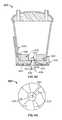
- the canister 620may include a centrally spinning magnetic stirring element 622 configured to reside in a central recess 624 of a ring-shaped reflective insert 626 .
- the insert 626may comprise segmented reflective structures 628 with radial flow spaces 530 therebetween to facilitate indirect mixing of the canister contents located in imaging region 632 of the canister 610 between the inner wall 634 and the segmented reflective structures 628 .
- the agitator motor or driver 636may be located in the bottom wall 638 of the mount 640 , surrounded by the scale 642 .
- the scalemay be mounted below the agitator driver, and essentially monitors of the weight of the entire mount, computing device, canister and canister contents, such that prior to initiating blood monitoring, the tare weight of mount, computing device and empty canister is measured to provide a corrective value and zero the measured weight prior to fluid collection.
- the mount 640includes an agitator driver 636 configured to couple to an agitator element 622 arranged within the canister 620 .
- the agitator driver 636can include a magnetic element 644 (e.g., an electromagnet, a rare-earth magnetic) eccentrically mounted to a rotary motor 646 arranged below the base 638 of the mount 640 .
- the systemcan intermittently actuate the rotary motor 646 , thereby rotating the magnetic element 644 , which magnetically couples to and rotates the agitator element 622 , thereby dispersing sediment collected on the base of the canister and/or agitating contents in the canister to achieve a more uniform mixture of fluid, solids, particulate, etc. (e.g., red blood cells, plasma, saline, fat, clotted blood, etc.) in the canister prior to imaging.
- fluid, solids, particulate, etc.e.g., red blood cells, plasma, saline, fat, clotted blood, etc.
- the centrally spinning magnetic stirring element 622may be configured to reside in a central recess 624 of a ring-shaped reflective insert 626 .
- the insert 626may comprise segmented reflective structures 628 with radial flow spaces 530 therebetween to facilitate indirect mixing of the canister contents located in imaging region 632 of the canister 610 between the inner wall 634 and the segmented reflective structures 628 .
- the agitator driver 636may be located in the bottom wall 638 of the mount 640 , surrounded by the scale 642 .
- the scalemay be mounted below the agitator driver, and essentially monitors of the weight of the entire mount, computing device, canister and canister contents, such that prior to initiating blood monitoring, the tare weight of mount, computing device and empty canister is measured to provide a corrective value and zero the measured weight prior to fluid collection.
- the canister 650comprises a rotatable paddle 652 with a central drive shaft 654 and vertical paddle elements 656 attached to the central drive shaft 644 via horizontal paddle elements 658 .
- the vertical paddle elements 656are configured to directly agitate the imaging space 660 between the wall 662 and the reflective structure 664 .
- the drive shaft 644protrudes from the base 666 of the canister 650 and a seal 688 is provided to resist canister leakage.
- the drive shaft 644is received in a drive shaft recess 670 rotated by a motor 672 .
- the canistercan include any other suitable type of agitator element remotely configured to be remotely actuated to stir or redistribute contents of the canister. Additional examples are provided below.
- the imaging systemmay generally include: an optical emitter 128 configured to illuminate the reflective insert 116 through the translucent section 114 of the canister 102 ; and a camera 130 configured to capture a digital photographic image of a volume of fluid contained in the canister 102 .
- the camera 130functions to capture digital color (e.g., photographic) images of a volume of fluid in the canister 102 .
- the camera 130can include a digital (e.g., CMOS or CCD) RGB camera.
- the optical emitter 128is typically offset (e.g., laterally) from the camera 130 and configured to illuminate a volume of fluid contained in the canister 102 for imaging by the camera 130 .
- the optical emitter 128may be configured to output a controlled amount of light (e.g., light flux, lumens) such that the camera 130 can repeatedly capture color data through a depth of the fluid in the canister 102 despite ambient lighting conditions.
- the optical emitter 128may output sufficient light and camera 130 may capture images with sufficiently fast shutter speeds such that images captured by the camera contain color data of sufficiently quality to be transformed into sufficiently accurate estimations of the concentration of one or more blood components in the canister 102 , and such that the effect of ambient light on the color of the volume of fluid recorded in an image is relatively insignificant.
- the imaging system 126may include a camera 130 and a flash element or optical emitter 128 integrated into a standalone computing device, such as a smartphone, a tablet, or a personal media player.
- the computing devicecan execute a native image processing application that locally performs the method described below.
- the computing devicecan also include a display 180 , opposite the camera 130 and an optical emitter 128 , and configured to display or render a weight or volume of contents of the canister 102 , a composition of fluid contained in the canister 102 (e.g., a concentration or volume fraction of hemoglobin, red bloods cells, or whole blood, etc.
- a prompt to empty the canister if fluid in the canister is approaching a maximum fill levela prompt to empty the canister or to stir the contents of the canister if sediment is obscuring the camera, or a prompt to salvage red blood cells from the contents of the canister, such as described below.
- the mount 104is typically configured to engage an exterior surface 118 of the canister 102 .
- the mount 104may also comprise or define a first window 120 configured with a first surrounding seal 122 a/b to seal over the exterior surface 118 of the canister 102 proximal the translucent section 114 , and to further comprise or define a second window 124 adjacent the first window 120 and configured with a second surrounding seal 182 a/b to seal over the exterior surface 118 of the canister proximal the translucent section, wherein the first window is substantially optically isolated from the second window.
- the mountis configured to support the optical emitter 128 and the camera 130 adjacent and facing the canister 102 and to isolate the camera 130 from light outside of the canister, e.g., ambient light, light output by the optical emitter 128 but not reflected by or refracted through fluid in the canister 102 .
- the mount 104is configured to receive and support the base 158 of the canister 102 .
- the mount 104defines a frusto-conical receptacle 184 sized to fit the canister 102 , as shown in FIG. 2A , and includes an optional latch 186 configured to transiently mate with a recess or an engagement feature 188 on the vessel 102 , thereby constraining the canister 102 in the mount.
- the canister 102can be inserted into the receptacle 184 , and the latch 186 can engage the canister 102 once the base 158 of the canister 102 meets the base 190 of the receptacle 184 ; the latch 186 can then be withdrawn to release the canister 102 for disposal or emptying.
- the mountcan include a conical receptacle defining a conical angle matched to the conical angle of the canister.
- the canistercan be inserted into the conical receptacle, and the weight of the canister can compress the walls of the canister against the interior surface of the conical receptacle.
- the mountincludes a belted or elastic strap configured to wrap around a canister and to retain an interior surface of the mount against an exterior surface of the canister.
- the canistermay also be configured with a groove or recess to receive the strap.
- the mountcan define first and second windows—for the optical emitter and the camera, respectively—that intersect the interior surface of the receptacle to meet the exterior surface of a canister when the canister is installed in the mount.
- the mount 104comprises a computing device receptacle 192 that is configured to transiently receive a standalone computing device 131 (as described above) and to support the computing device 131 with its camera 130 and optical emitter 128 or flash element facing the canister 102 , as shown in FIG. 1 .
- the mount 104can support the computing device 131 in a vertical orientation such that the optical axis of the camera 130 is substantially normal to an adjacent exterior surface 118 of the canister 102 ; proximal the base 158 of the canister 102 to optically detect and analyze a relatively small volume of fluid in the canister through the transparent region 114 of the canister 102 located between the canister wall 142 and the reflective insert 116 , and vertically offset above the base 158 of the canister 102 such that a volume of sediment may collect on the base 158 of the canister 102 without immediately obscuring the optical emitter and/or the camera, as shown in FIG. 2A .
- the mount 104can also support the computing device 131 at an offset from the wall 142 of the canister 102 such that a minimum width and/or height of the reflective insert 116 remains within the field of view of the camera 130 .
- the mountcan define any other geometry or function in any other way to transiently couple the optical emitter and the camera to the canister, and vice versa.
- the computing device receptaclemay be a modular or adjustable receptacle, to permit the use of different computing devices with the system, e.g. an IOS, Android, Windows or Linux tablet/cellphone, or camera system.
- a lensmay be provided in the optical path of the second window corresponding to the camera 130 . A lens may facilitate focused image capture, which may be used to detect and/or characterize sediment or other materials found in the canister.
- the mount 104defines a first window 120 configured to align with the optical emitter 128 and a second window 124 configured to align with the camera 130 .
- the first window 120is configured to pass light from the optical emitter 128 to the wall 142 of the canister 102 , which passes light into fluid in the canister 102 and onto the reflective insert 116 , thereby illuminating the fluid and the reflective insert 116 ;
- the second window 124is configured to pass light reflected and refracted out of the wall 142 of the canister 102 by the reflective insert 116 and the fluid into the camera 130 .
- the mount 104can include a first seal 122 a around a perimeter of a first side of the first window 120 and configured to seal the first window 120 against the exterior surface 118 of the canister 102 when the canister 102 is installed in the mount 104 ; a second seal 122 b around a perimeter of the opposite side of the first window 120 and configured to seal the first window 120 against an exterior surface of the computing device 131 —around the optical emitter 128 —when the computing device 131 is installed in the mount 104 , as shown in FIG. 2B .
- the first seal 122 a and the second seal 122 bmay an integrally formed window seal or grommet spanning both surfaces of the window 120 .
- the mountcan include: a third seal 182 a around a perimeter of a first side of the second window 124 and configured to seal the second window 124 against the exterior surface 118 of the canister 102 when the canister 102 is installed in the mount 104 ; a fourth seal 182 b around a perimeter of the opposite side of the second window 124 and configured to seal the second window 124 against an exterior surface 118 of the computing device 131 —around the camera 130 —when the computing device 131 is installed in the computing device receptacle 184 of the mount 104 .
- the third and fourth seals 182 a/bmay be separate seals or an integrally formed window seal or grommet spanning both surfaces of the second windows 124 .
- a single figure-eight sealmay be used for the optical emitter 128 and camera 130 .
- the seals 122 a/b and 182 a/bcan include opaque flexible seals to minimize crosstalk (e.g., light bleed) between the optical emitter 128 and the camera 130 outside of the canister 102 .
- the mount 104can include soft, black silicone O-rings configured to abut and compress between the inter-recess wall structure 194 of the mount 104 and the canister 102 (e.g., the first and third seals 122 a , 182 a ) and to abut and compress between the inter-recess wall structure 194 of the mount 104 and the computing device 131 (e.g., the second and fourth seals 122 b , 182 b ).
- the mount 104can include soft, black silicone O-rings configured to abut and compress between the inter-recess wall structure 194 of the mount 104 and the canister 102 (e.g., the first and third seals 122 a , 182 a ) and to abut and compress between the inter-recess wall structure 194 of the mount 104 and the computing device 131 (e.g., the second and fourth seals 122 b , 182 b ).
- the weighing scale 106may be coupled to the mount 104 and be configured to output a signal corresponding to a weight of contents in the canister 102 .
- the mount 104 of the system 100is configured to rest on a horizontal surface
- the weighing scale 106is coupled to the mount 104 opposite the canister 102 and outputs a signal corresponding to the weight of the mount 104 , the computing device 131 , the canister 102 , fluid in the canister, etc. above, as shown in FIG. 2A .
- the weighing scale 104can include a footing or resilient friction pad 196 configured to sit on a horizontal surface and a strain gauge 198 interposed between the mount 104 and the footing 196 .
- the systemis configured to hang, such as from a hook on the operating room table or IV pole, and the weighing scale is arranged between the lid and the hook and configured to output a signal corresponding to the weight of the mount, the computing device, the canister, the lid, fluid in the canister, etc. below.
- the systemcan include a weighing scale of any other type and coupled to the mount or to the canister in any other suitable way.
- the processormay receive weight information from the scale in a continuous or a variable manner.
- the sampling rate for the weightmay be in the range of about 1000 Hz to about once every 5 minutes, or about 60 Hz to about 1 Hz.
- the sampling rate of the scalemay be increased, as well as image capture rate or illumination rate of the imaging system.
- the scalemay also be used to indicate other states of events relating to canister use.
- the complete unweighting of the scale, or reduction of weight below the tare weight of the canistermay be used to indicate removal of the canister.
- the detected weightmay increase in a generally linear fashion while suctioning liquid material, but may exhibit some variation when suctioning mixtures of liquid and solid or semi-solid materials or tissue.
- the weightmay also oscillate when the suction device is used at a liquid/air interface and the processor of the system may be configured to detect such states and to wait for the oscillations to stop before reporting any weight changes.
- the systemtypically comprises a processor that may be configured to transform an image captured by the color camera into an estimated concentration of a blood component in a fluid within the canister and to estimate an amount of the blood component in the canister based on the estimated concentration of the blood component and an output of the weighing scale.
- the processingfunctions to locally execute one or more aspects of the method described below.
- the processor 132can be similarly integrated into the computing device 131 .
- the computing device 131can communicate with the weighing scale 106 and/or with an electromechanical valve coupled to the lid or in the lid via a wired connection to a port in the computing device.
- the systemcan include a short-range wireless communication module, such as NFC or Bluetooth or wireless USB, electrically coupled to the weighing scale and/or to the electromechanical valve, and the computing device 131 can wirelessly pair with the wireless communication module to receive outputs from the weighing scale and/or to control the state of the valve.
- the camera, the optical emitter, the digital display, and the processorare integrated into the mount.
- the systemcan include any other integrated or discrete elements that cooperate to collect fluid from a suction wand, to weigh the fluid, to image the fluid, to transform images of the fluid into estimations of the quality of the fluid, and to generate estimations of the quantity of one or more blood components in the fluid over time.
- FIG. 3depicts an illustrative method that may be suitable for use with the systems described herein.
- a method S 100 for estimating an amount of a blood component in a volume of fluidmay include illuminating an insert 116 within a canister 102 according to an illumination schedule; capturing an image of the insert (via an optical detector or camera offset from the optical emitter), estimating a concentration of a blood component in a fluid within the canister e.g., based on the illumination schedule, color intensities of pixels in the image, and a color gradient from a first region to a second region in the image, where the first region corresponds to proximity to the optical emitter, and the second region corresponds to remoteness from the optical emitter.
- the methodmay be executed locally by the system 100 described above to automatically capture an image of a (sub-)volume of fluid contained in a canister 102 and to transform absolute color values in the image and/or color gradients across pixels in the image into a quantitative estimation of a concentration of a blood component in the canister 102 .
- the system 100may transform an image into an estimation of a mass per unit volume of hemoglobin, a volume fraction of red blood cells, or a volume fraction of whole blood, etc. of fluid contained in the canister.
- the system 100may actuate an optical emitter to illuminate the volume of fluid in S 110 , triggers a camera to capture an image in S 120 , and processes the image to generate a blood component concentration estimation in S 130 .
- the light source or optical emitter and the camera or optical detectormay be provided in the computing device 131 , or may be integrated into the mount 104 .
- the method described hereinmay be executed locally by the system, e.g. the computing device 131 , for estimating an amount of a blood component in a volume of fluid described above. However, portions of the method may additionally or alternatively be executed remotely from the system, such as by another local computing device connected to the system, by a local distributed network, or by a remote server.
- the methodmay further comprise at S 110 illuminating an insert 116 within a canister 104 according to an illumination schedule (e.g., using an optical emitter); and at S 120 , capturing an image of the insert 116 (e.g., using an optical detector).
- an illumination schedulee.g., using an optical emitter
- capturing an image of the insert 116e.g., using an optical detector.
- the systemis configured to illuminate the reflective insert 116 within the canister 102 —and therefore a volume of fluid between the reflective insert and the camera—and to capture an image of the illuminated volume of fluid located between the insert 116 and the wall 142 of the canister 102 .
- the system 100powers on the optical emitter at a static, preset illumination power in S 110 , triggers the camera to capture an image in S 120 , and then deactivates the optical emitter.
- the power levelmay be in the range of 1 lumen to 1,000 lumens, or about 3 lumens to about 100 lumens, or about 3 lumens to about 50 lumens, or about 5 lumens to about 20 lumens, or about 15 lumens to 30 lumens, about or may be anywhere from 1% to 100% or about 30% to about 100%, or about 70% to about 100% of the light source's maximum power.
- the system 100first activates the optical emitter at a select illumination power, such as by pulse-width modulating the optical emitter at a selected duty cycle, in order to achieve target brightness in an image subsequently captured by the camera.
- the system 100can pulse-width modulate the optical emitter at frequency greater than a fastest shutter speed implemented by the camera (e.g., 500 Hz for a camera operable at a maximum shutter speed of 1/100 s).
- the systemthen triggers the camera to capture an image in Block S 120 , such as 0.002 second after the optical emitter is activated in Block S 110 .
- the systemcan deactivate the optical emitter.
- the processormay be configured to initiate image capture upon a signal from the scale indicating a change in the weight of the canister contents.
- the system 100can progress through a set of duty cycles—such as down from 100% duty or up from 0% in 1%, 5%, 10%, 20% duty increments—and capture an image at each duty until the camera captures an image that meets one or more target color parameters, such as a lightest color limit, a darkest color limit, or target color gradient between the first region and the second region of the image.
- the systemcan increase the duty cycle of the optical emitter—starting at 0%—and capture an image for each duty cycle through the camera until a captured image contains a contiguous horizontal line of pixels containing less than a threshold number of black pixels or pixels darker than a threshold dark color value.
- the systemcan scan a single horizontal line of pixels centered vertically in the image and count a number of consecutive pixels (or a total number of pixels) along the scan line containing the color black or containing a color value less than (i.e., darker than) a threshold darkness value.
- the systemcan reject the image, increase the duty cycle of the optical emitter, capture a subsequent image through the camera, and similarly process the subsequent image.
- the systemcan repeat this process until a final image with a number of consecutive pixels (or total number of pixels) along a scan line less than the threshold count is captured.
- the systemcan then process this final image in Block S 130 , as described below.
- the systemcan decrease the duty cycle of the optical emitter—starting from 100%—and capture an image for each duty cycle through the camera until a captured image contains a contiguous horizontal line of pixels containing less than a threshold number of white pixels or pixels lighter than a threshold light color value.
- the systemcan repeat the foregoing process, starting with a low duty cycle (e.g., 0%) or a high duty cycle (e.g., 100%) at the optical emitter and then increase or decrease the duty cycle, respectively, until a suitable image is captured at the camera.
- a low duty cyclee.g., 0%
- a high duty cyclee.g., 100%
- the systemcan begin a new imaging period by setting the optical emitter to implement a last duty cycle from the preceding imaging period.
- the systemcan then capture a first image in the new imaging period through the camera, either increase or decrease the duty cycle of the optical emitter if the first image contains an excess number of black or dark pixels or if the first image contains an excess number of white or light pixels, respectively, capture and process a subsequent image, and then repeat the foregoing until an image containing color data of suitable quality is achieved.
- the systemcan thus vary the illumination power output by the optical emitter and process images captured under various illumination powers in order to identify and record an image containing a suitable quality of color data that can be transformed into a quality (e.g., a blood component concentration) of a volume of fluid in the canister.
- a qualitye.g., a blood component concentration
- the systemmay set an illumination power (by setting a duty cycle) of the optical emitter and then vary the shutter speed of the camera—and therefore an exposure of an image captured with the camera—to achieve an image with a quality of color data suitable for transformation into a quality of the volume of fluid in the canister.
- the systemmay operate the optical emitter at a duty cycle of 100%; decrease the shutter speed of the camera (e.g., from 1/200 s to 1/100 s, then 1/30 s, 1/20 s, 1/15 s, 1/12 s, etc.); and capture an image through the camera for each shutter speed until a captured image contains a contiguous horizontal line of pixels containing less than a threshold number of black pixels or pixels darker than a threshold dark color value.
- the systemmay implement any other method or technique to set an illumination power, a shutter speed, or any other illumination or image-capture parameter for the imaging system.
- the systemmay implement any other method or technique to confirm that an image captured by the camera—for a given set of illumination and image-capture parameters—contains sufficient color data for transformation into a quality of fluid within the canister.
- the systemmay also manipulate multiple illumination and image capture parameters—such as both a duty of the optical emitter and a shutter speed of the camera—to achieve a target color quality in an image.
- the systemcan therefore capture multiple images during a single imaging period and discard all but a single image containing sufficient color data for transformation into a quality (e.g., a blood component concentration) of a volume of fluid contained in the canister.
- the systemmay tag this select image with illumination and/or image capture parameters executed by the imaging system to capture the select image, such as the duty implemented by the optical emitter and/or the shutter speed implemented by the camera when the select image was captured.
- the systemcan then select a set of template images based on these illumination and image capture parameters for comparison to the select image or insert these illumination and image capture parameters into a parametric model that is then applied to color values in select images, as described below.
- the systemcaptures multiple images at different illumination and/or image-capture parameters in Blocks S 110 and S 120 .
- the systemmay: set the optical emitter at 0% duty and capture a first image; set the optical emitter at 50% duty and capture a second image; and then set the optical emitter at 100% duty and capture a third image.
- the systemmay: step the duty of the optical emitter upward from a minimum duty (e.g., 0%); capture an image at each duty step; store a first image including a total number of black pixels less than a threshold number of black pixels; and store a last image including a total number of white pixels less than a threshold number of white pixels (or vice versa).
- the systemmay: set the duty cycle of the optical emitter (e.g., at a static value of 80%); step the shutter speed downward from a maximum shutter speed (e.g., 1/200 s); capture an image at each shutter speed; store a first image including a total number of black pixels less than a threshold number of black pixels; and store a last image including a total number of white pixels less than a threshold number of white pixels (or vice versa).
- a maximum shutter speede.g. 1/200 s
- the systemmay manipulate any other illumination and/or image capture parameter across a set of images.
- the systemmay then process this set of images in Block S 130 to estimate a quality of the fluid within the canister during the corresponding imaging period.
- Block S 130 of the methoddepicts, color intensities of pixels in the image 300 , and a color gradient 302 from a first region 304 to a second region 306 in the image 300 , estimating a concentration of a blood component in a fluid within the canister, the first region 304 corresponding to proximity to the optical emitter, and the second region 306 corresponding to remoteness from the optical emitter.
- the systemtransforms color values contained in pixels in an image 300 captured by the camera into one or more of: a concentration of red bloods cells; a concentration of hemoglobin; a proportion of whole blood cells to lysed red blood cells (or free hemoglobin); a concentration of whole blood; a concentration of plasma; a concentration of white blood cells; etc.
- the systemcan implement parametric and/or non-parametric (e.g., template-matching) techniques to transform color data contained in an image 300 captured by the camera into a blood component concentration value for a volume of fluid contained in the canister, such as described, for example, in U.S. patent application Ser. Nos. 13/544,664 and 13/738,919.
- parametric and/or non-parametrice.g., template-matching
- the systemimplements template matching techniques to match one or more color values (e.g., intensity in the red color space) in an image captured by the camera to a template image of a fluid of known blood component concentration and stored in (local or remote) memory.
- the systemcan match a color gradient from a first side of the image (corresponding to a shortest distance to the optical emitter) to an opposite side of the image (corresponding to a greatest distance from the optical emitter) to a template gradient of one or more known blood component proportions.
- the systemmay select a single template image containing a lightest color, a darkest color, and/or a linear or non-linear color gradient nearest the lightest color, darkest color, and/or color gradient represented in the current image and assign one or more blood component concentration values associated with the template image to the current image.
- the systemmay select two or more template images exhibiting lightest colors, darkest colors, and/or color gradients nearest those of the current image and then average blood component concentration values associated with these template images to generate an estimation of a blood component concentration in the canister at a time the current image was captured.
- the systemmay apply template images from multiple template image sets—each image template set corresponding to a subset of known blood component concentration values—to the current image in order to generate estimations of multiple blood component concentrations representative of a volume of fluid contained in the canister from a single image of the canister.
- the systemmay match a difference between a lightest color value and a darkest color value in the current image to a template image in a first template image set to generate an estimation of the concentration of hemoglobin in the volume of fluid in the canister; the system may then match a non-linear color gradient between the first side of the image and the second side of the image to a template image in a second template image set to generate an estimation of the proportion of lysed red blood cells in the volume of fluid in the canister.
- the systemmay select or filter available template images based on illumination and image-capture parameters implemented by the imaging system to capture the current image. For example, the system may set the duty of the optical emitter at 70% percent, capture an image, and then select a template image set containing template images captured by similar systems with optical emitters operating at 70% duty. In another example, the system may set the duty of the optical emitter at 100% percent, set the shutter speed of the camera at 1/20 s, capture an image, and then select a template image set containing template images captured by similar systems with optical emitters operating at 100% duty and cameras operating at a shutter speed of 1/20 s.
- the systemmay implement any other method or technique to select a template image of known blood component concentration and to match the template image to a current image captured by the camera to generate an estimation of a blood component concentration in a volume of fluid contained in the canister at a time the current image was captured.
- the systempasses quantitative data represented in one or more pixels in the current image into a parametric model that outputs a quantitative estimation of the concentration of one or more blood components in a volume of fluid contained in the canister, as shown in FIG. 3 .
- the systemmay pass a color value in a single lightest pixel (or in a small cluster of lightly-colored pixels) and a color value in a single darkest pixel (or in a small cluster of relatively dark pixels) in the current image into the parametric model.
- the systemcan: separate the current image into ten 200-pixel-wide, 1000-pixel tall columns; average the intensity of each column in the red, green, and blue component spaces; and pass these thirty intensity values into a parametric model that transforms these values into an estimation of the concentration of one or more blood components in the volume of fluid in the canister at the time the current image was captured.
- the systemmay also calculate coefficients of a linear, logarithmic, polynomial, power, or other trendline of the color gradient from the first region of the image (e.g., a pixel or pixel cluster of lightest color) to the second region of the image (e.g., a pixel or pixel cluster of darkest color) and pass these coefficient values into a parametric model.
- the systemmay also identify a trendline type (e.g., linear, logarithmic, or polynomial, etc.) that best fits the color gradient represented in the current image, select a parametric model for the identified trendline type, and then pass coefficients of a trendline of the identified trendline type into the selected parametric model to generate an estimation of the concentration of the blood component in the canister.
- a trendline typee.g., linear, logarithmic, or polynomial, etc.
- the systemmay also pass illumination and/or image-capture parameters implemented by the imaging system to capture the current image—such as a duty of the optical emitter or the shutter speed of the camera—into the parametric model.
- the systemmay select a particular parametric model from a set of available parametric models based on the illumination and/or image-capture parameters implemented by the imaging system to capture the current image; the system may then pass color values of pixels in the current image into the selected parametric model to output an estimation of a blood component concentration in the canister.
- the systemmay also implement any of the foregoing methods and techniques to compare absolute color values or color gradients across two or more images in a set of images.
- the systemmay capture two images of the volume of fluid in the canister under two distinct lighting conditions (e.g., 20% duty and 80% duty at the optical emitter) and then characterize a difference in the color gradients across both images as a concentration of whole red blood cells and a concentration of free hemoglobin in the volume of fluid in the canister.
- the systemmay implement any other parametric or non-parametric techniques to transform color data contained in one or more images captured by the camera into an estimation of a quality of a volume of fluid contained in the canister.
- the systemdetermines a quality of an image output, as depicted in Block S 120 , and selectively discards this image or passes this image on to the next step of the process.
- the systemscans the image vertically (e.g., along one or more vertical columns of pixels in the image) for a sharp shift in color value from a lower region of the image to an upper region of the image. The system may then correlate this color shift with collection of sediment on the bottom of the vessel, discard the image, and/or trigger manual or automatic removal of sediment from the field of view of the camera if such a color shift is detected in the image.
- an image captured by the camera after sediment has collected in the field of view of the cameramay contain a contiguous column of relatively dark pixels corresponding to a segment, extending upwardly from the bottom of the image, and rapidly transitioning into a contiguous column of relatively bright pixels corresponding to the reflective insert (and to fluid between the wall of the canister and the reflective insert).
- the systemmay scan one or more vertical columns of pixels in an image captured by the camera and then discard the image as containing insufficient color data of the fluid if a column of pixels in the image includes a transition from a line of dark pixels to a line of light pixels (or if the image includes more than a threshold number of dark pixels in a vertical column of dark pixels below a line of light pixels).
- the systemcan issue an audible or visual prompt (e.g., through the display) to agitate the contents of the vessel.
- the systemcan then sample an integrated accelerometer to determine if the canister has been agitated or continue to capture and analyze images to determine if sediment has been removed from the field of view of the camera.
- the systemcan automatically activate an agitator—as described above—to mix contents and redistribute sediment within the canister prior to capturing.
- the systemcan activate the agitator for a preset period of time (e.g., 10 seconds) or until images captured by the camera no longer exhibit such a sharp shift in color value.
- a preset period of timee.g. 10 seconds
- the systemcan deactivate the agitator, pause for a period of time (e.g., five seconds) to allow fluid within the canister to slow, and then execute Blocks S 110 , S 120 , and S 130 as described above to capture and process an image of fluid in canister.
- the systemcan remove (e.g., crop) a region of the current image correlated with obscuration by sediment and pass the remainder of the current image to Block S 130 for processing.
- the systemmay implement any other method or technique to confirm the quality of images captured by the camera and selectively pass on and/or reject these images.
- the systemmay also sample the weighing scale and apply a value output by the weighing scale to the blood component concentration value to estimate a quantity (e.g., a volume, a mass) of the blood component in the canister in Block S 140 .
- the system 100continuously samples the weighing scale and records outputs of the weighing scale 106 with corresponding timestamps in memory.
- the system 100can retrieve—from memory—a weighing scale output value (e.g., weight) recorded at a time nearest a time that the image 300 was captured.
- the system 100can also retrieve multiple weighing scale outputs recorded around the time that the image was captured and then average these values.
- the system 100can then divide this weighing scale output value for the imaging period by a static estimated density of fluid collected in the canister 102 (e.g., 1030 kg/m 3 for a mixture of saline and blood) to estimate the volume of fluid in the canister.
- a static estimated density of fluid collected in the canister 102e.g., 1030 kg/m 3 for a mixture of saline and blood
- the systemcan estimate the volume (or mass) of the blood component (e.g., hemoglobin, red blood cells) in the canister, as depicted in Block S 150 .
- the blood componente.g., hemoglobin, red blood cells
- the systemcan repeat Blocks S 110 , S 120 , S 130 , S 140 , and S 150 throughout an operation—such as at a rate of 1 Hz—in order to update estimations of a volume of fluid in the canister, a quality of the volume of fluid, and/or a quantity of a blood component in the canister over time.
- the system 100may update an integrated display 180 over time to visually indicate a current estimated volume of fluid in the canister 102 , a current estimated quality of the volume of fluid, and/or a current estimated quantity of the blood component in the canister 102 , as shown in FIG. 3 .
- the system 100may also render prompts on the display 180 , such as a prompt to empty the canister 102 or a prompt to agitate the canister 102 due to collection of sediment in front of the imaging system.
- the systems and methods described hereincan be embodied and/or implemented at least in part as a machine configured to receive a computer-readable medium storing computer-readable instructions.
- the instructionscan be executed by computer-executable components integrated with the application, applet, host, server, network, website, communication service, communication interface, hardware/firmware/software elements of a user computer or mobile device, wristband, smartphone, or any suitable combination thereof.
- systemmay comprise, inter alia, components such as software modules, general-purpose CPU, RAM, etc. found in general-purpose computers, and/or FPGAs and/or ASICs found in more specialized computing devices.
- a servermay comprise components such as CPU, RAM, etc.
- the embodimentcan be embodied and/or implemented at least in part as a machine configured to receive a computer-readable medium storing computer-readable instructions.
- the instructionscan be executed by computer-executable components integrated by computer-executable components integrated with apparatuses and networks of the type described above.
- the computer-readable mediumcan be stored on any suitable computer readable media such as RAMs, ROMs, flash memory, EEPROMs, optical devices (CD or DVD), hard drives, floppy drives, or any suitable device.
- the computer-executable componentcan be a processor but any suitable dedicated hardware device can (alternatively or additionally) execute the instructions.
- the terms component, module, device, etc.may refer to any type of logical or functional circuits, blocks and/or processes that may be implemented in a variety of ways.
- the functions of various circuits and/or blockscan be combined with one another into any other number of devices.
- the devicescan comprise programming instructions transmitted to a general purpose computer or to processing/graphics hardware via a transmission carrier wave.
- the devicescan be implemented as hardware logic circuitry implementing the functions encompassed by the innovations herein.
- the devicescan be implemented using special purpose instructions (SIMD instructions), field programmable logic arrays or any mix thereof which provides the desired level performance and cost.
- aspects of the method and system described herein, such as the logicmay also be implemented as functionality programmed into any of a variety of circuitry, including programmable logic devices (“PLDs”), such as field programmable gate arrays (“FPGAs”), programmable array logic (“PAL”) devices, electrically programmable logic and memory devices and standard cell-based devices, as well as application specific integrated circuits.
- PLDsprogrammable logic devices
- FPGAsfield programmable gate arrays
- PALprogrammable array logic
- Some other possibilities for implementing aspectsinclude: memory devices, microcontrollers with memory (such as EEPROM), embedded microprocessors, firmware, software, etc.
- aspectsmay be embodied in microprocessors having software-based circuit emulation, discrete logic (sequential and combinatorial), custom devices, fuzzy (neural) logic, quantum devices, and hybrids of any of the above device types.
- the underlying device technologiesmay be provided in a variety of component types, e.g., metal-oxide semiconductor field-effect transistor (“MOSFET”) technologies like complementary metal-oxide semiconductor (“CMOS”), bipolar technologies like emitter-coupled logic (“ECL”), polymer technologies (e.g., silicon-conjugated polymer and metal-conjugated polymer-metal structures), mixed analog and digital, and so on
- MOSFETmetal-oxide semiconductor field-effect transistor
- CMOScomplementary metal-oxide semiconductor
- ECLemitter-coupled logic
- polymer technologiese.g., silicon-conjugated polymer and metal-conjugated polymer-metal structures
- mixed analog and digitaland so on
Landscapes
- Health & Medical Sciences (AREA)
- Engineering & Computer Science (AREA)
- Life Sciences & Earth Sciences (AREA)
- Biomedical Technology (AREA)
- Hematology (AREA)
- Physics & Mathematics (AREA)
- Heart & Thoracic Surgery (AREA)
- General Health & Medical Sciences (AREA)
- General Physics & Mathematics (AREA)
- Chemical & Material Sciences (AREA)
- Veterinary Medicine (AREA)
- Public Health (AREA)
- Animal Behavior & Ethology (AREA)
- Anesthesiology (AREA)
- Vascular Medicine (AREA)
- Signal Processing (AREA)
- Multimedia (AREA)
- Analytical Chemistry (AREA)
- Biophysics (AREA)
- Immunology (AREA)
- Pathology (AREA)
- Biochemistry (AREA)
- Molecular Biology (AREA)
- Medicinal Chemistry (AREA)
- Food Science & Technology (AREA)
- Ecology (AREA)
- Urology & Nephrology (AREA)
- External Artificial Organs (AREA)
- Investigating Or Analysing Materials By Optical Means (AREA)
- Investigating Or Analysing Biological Materials (AREA)
Abstract
Description
Claims (39)
Priority Applications (4)
| Application Number | Priority Date | Filing Date | Title |
|---|---|---|---|
| US15/389,365US10641644B2 (en) | 2012-07-09 | 2016-12-22 | System and method for estimating an amount of a blood component in a volume of fluid |
| US16/841,464US11333545B2 (en) | 2015-12-23 | 2020-04-06 | System and method for estimating an amount of a blood component in a volume of fluid |
| US17/725,686US12209899B2 (en) | 2015-12-23 | 2022-04-21 | Systems and methods for estimating a blood volume within a canister |
| US19/029,263US20250164305A1 (en) | 2015-12-23 | 2025-01-17 | Systems And Methods For Estimating A Blood Component Within A Canister |
Applications Claiming Priority (4)
| Application Number | Priority Date | Filing Date | Title |
|---|---|---|---|
| US13/544,664US9652655B2 (en) | 2011-07-09 | 2012-07-09 | System and method for estimating extracorporeal blood volume in a physical sample |
| US13/738,919US8983167B2 (en) | 2012-05-14 | 2013-01-10 | System and method for estimating a quantity of a blood component in a fluid canister |
| US201562387234P | 2015-12-23 | 2015-12-23 | |
| US15/389,365US10641644B2 (en) | 2012-07-09 | 2016-12-22 | System and method for estimating an amount of a blood component in a volume of fluid |
Related Child Applications (1)
| Application Number | Title | Priority Date | Filing Date |
|---|---|---|---|
| US16/841,464ContinuationUS11333545B2 (en) | 2015-12-23 | 2020-04-06 | System and method for estimating an amount of a blood component in a volume of fluid |
Publications (2)
| Publication Number | Publication Date |
|---|---|
| US20170184442A1 US20170184442A1 (en) | 2017-06-29 |
| US10641644B2true US10641644B2 (en) | 2020-05-05 |
Family
ID=59087053
Family Applications (4)
| Application Number | Title | Priority Date | Filing Date |
|---|---|---|---|
| US15/389,365ActiveUS10641644B2 (en) | 2012-07-09 | 2016-12-22 | System and method for estimating an amount of a blood component in a volume of fluid |
| US16/841,464Active2037-02-19US11333545B2 (en) | 2015-12-23 | 2020-04-06 | System and method for estimating an amount of a blood component in a volume of fluid |
| US17/725,686Active2038-01-26US12209899B2 (en) | 2015-12-23 | 2022-04-21 | Systems and methods for estimating a blood volume within a canister |
| US19/029,263PendingUS20250164305A1 (en) | 2015-12-23 | 2025-01-17 | Systems And Methods For Estimating A Blood Component Within A Canister |
Family Applications After (3)
| Application Number | Title | Priority Date | Filing Date |
|---|---|---|---|
| US16/841,464Active2037-02-19US11333545B2 (en) | 2015-12-23 | 2020-04-06 | System and method for estimating an amount of a blood component in a volume of fluid |
| US17/725,686Active2038-01-26US12209899B2 (en) | 2015-12-23 | 2022-04-21 | Systems and methods for estimating a blood volume within a canister |
| US19/029,263PendingUS20250164305A1 (en) | 2015-12-23 | 2025-01-17 | Systems And Methods For Estimating A Blood Component Within A Canister |
Country Status (4)
| Country | Link |
|---|---|
| US (4) | US10641644B2 (en) |
| EP (1) | EP3393539B1 (en) |
| JP (2) | JP6968427B2 (en) |
| WO (1) | WO2017112913A1 (en) |
Cited By (9)
| Publication number | Priority date | Publication date | Assignee | Title |
|---|---|---|---|---|
| US11333545B2 (en) | 2015-12-23 | 2022-05-17 | Gauss Surgical, Inc. | System and method for estimating an amount of a blood component in a volume of fluid |
| US11617625B2 (en) | 2019-03-12 | 2023-04-04 | Medline Industries, Lp | Systems, apparatus and methods for properly locating items |
| US11727572B2 (en) | 2015-05-15 | 2023-08-15 | Gauss Surgical Inc. | Methods and systems for characterizing fluids from a patient |
| WO2023244824A2 (en) | 2022-06-17 | 2023-12-21 | Stryker Corporation | Estimation of blood loss within a waste container of a medical waste collection system |
| US11925422B2 (en) | 2017-05-26 | 2024-03-12 | Medline Industries, Lp | Systems, apparatus and methods for continuously tracking medical items throughout a procedure |
| US12059276B2 (en) | 2019-08-21 | 2024-08-13 | Medline Industries, Lp | Systems, apparatus and methods for automatically counting medical objects, estimating blood loss and/or communicating between medical equipment |
| US12207924B2 (en) | 2015-05-15 | 2025-01-28 | Stryker Corporation | Systems and methods for assessing fluids from a patient |
| US12322275B2 (en) | 2011-07-09 | 2025-06-03 | Stryker Corporation | Method for estimating a quantity of a blood component in a fluid receiver and corresponding error |
| WO2025137440A1 (en) | 2023-12-20 | 2025-06-26 | Stryker Corporation | Estimation of blood loss within a waste container of a medical waste collection system |
Families Citing this family (47)
| Publication number | Priority date | Publication date | Assignee | Title |
|---|---|---|---|---|
| US11806266B2 (en) | 2014-03-19 | 2023-11-07 | Purewick Corporation | Apparatus and methods for receiving discharged urine |
| US10952889B2 (en) | 2016-06-02 | 2021-03-23 | Purewick Corporation | Using wicking material to collect liquid for transport |
| US11376152B2 (en) | 2014-03-19 | 2022-07-05 | Purewick Corporation | Apparatus and methods for receiving discharged urine |
| US10390989B2 (en) | 2014-03-19 | 2019-08-27 | Purewick Corporation | Apparatus and methods for receiving discharged urine |
| US10226376B2 (en) | 2014-03-19 | 2019-03-12 | Purewick Corporation | Apparatus and methods for receiving discharged urine |
| US10376406B2 (en) | 2016-07-27 | 2019-08-13 | Purewick Corporation | Male urine collection device using wicking material |
| US10973678B2 (en) | 2016-07-27 | 2021-04-13 | Purewick Corporation | Apparatus and methods for receiving discharged urine |
| US10288471B2 (en)* | 2016-09-01 | 2019-05-14 | Aaron Adams | Process, application and scale to be used in the measurement of the amount harvested organic plants |
| US10292511B2 (en)* | 2016-10-06 | 2019-05-21 | Anatoliy TKACH | Methods, system and apparatus to improve motivation and control when taking meals and to automate the process of monitoring nutrition |
| JP2020510464A (en) | 2017-01-31 | 2020-04-09 | ピュアウィック コーポレイション | Apparatus and method for receiving excreted urine |
| JP6959104B2 (en)* | 2017-11-02 | 2021-11-02 | 日東電工株式会社 | Drainage drainage management system |
| JP7098112B2 (en)* | 2017-11-28 | 2022-07-11 | 学校法人自治医科大学 | Drain drainage management support system |
| KR102513810B1 (en) | 2018-05-01 | 2023-03-24 | 퓨어윅 코포레이션 | Fluid collection devices, systems and methods |
| WO2019212952A1 (en) | 2018-05-01 | 2019-11-07 | Purewick Corporation | Fluid collection devices, related systems, and related methods |
| KR102492111B1 (en) | 2018-05-01 | 2023-01-27 | 퓨어윅 코포레이션 | Fluid Collection Devices and Methods of Using The Same |
| WO2019212950A1 (en) | 2018-05-01 | 2019-11-07 | Purewick Corporation | Fluid collection devices, related systems, and related methods |
| JP7093851B2 (en) | 2018-05-01 | 2022-06-30 | ピュアウィック コーポレイション | Fluid collecting clothing |
| CN111241889B (en)* | 2018-11-29 | 2023-05-12 | 荣耀终端有限公司 | Method and device for detecting and evaluating dark circles |
| US10915680B2 (en)* | 2018-12-21 | 2021-02-09 | Dassault Systemes Simulia Corp. | Local control of design patterns on surfaces for enhanced physical properties |
| WO2020256865A1 (en) | 2019-06-21 | 2020-12-24 | Purewick Corporation | Fluid collection devices including a base securement area, and related systems and methods |
| US12329364B2 (en) | 2019-07-19 | 2025-06-17 | Purewick Corporation | Fluid collection devices including at least one shape memory material |
| US12350190B2 (en) | 2020-01-03 | 2025-07-08 | Purewick Corporation | Urine collection devices having a relatively wide portion and an elongated portion and related methods |
| ES2969642T3 (en) | 2020-04-10 | 2024-05-21 | Purewick Corp | Fluid collection assemblies that include one or more leak prevention features |
| US12048643B2 (en) | 2020-05-27 | 2024-07-30 | Purewick Corporation | Fluid collection assemblies including at least one inflation device and methods and systems of using the same |
| USD967409S1 (en) | 2020-07-15 | 2022-10-18 | Purewick Corporation | Urine collection apparatus cover |
| US20220047410A1 (en) | 2020-08-11 | 2022-02-17 | Purewick Corporation | Fluid collection assemblies defining waist and leg openings |
| US12156792B2 (en) | 2020-09-10 | 2024-12-03 | Purewick Corporation | Fluid collection assemblies including at least one inflation device |
| US11801186B2 (en) | 2020-09-10 | 2023-10-31 | Purewick Corporation | Urine storage container handle and lid accessories |
| US12042423B2 (en) | 2020-10-07 | 2024-07-23 | Purewick Corporation | Fluid collection systems including at least one tensioning element |
| US12257174B2 (en) | 2020-10-21 | 2025-03-25 | Purewick Corporation | Fluid collection assemblies including at least one of a protrusion or at least one expandable material |
| US12208031B2 (en) | 2020-10-21 | 2025-01-28 | Purewick Corporation | Adapters for fluid collection devices |
| US12048644B2 (en) | 2020-11-03 | 2024-07-30 | Purewick Corporation | Apparatus for receiving discharged urine |
| US12070432B2 (en) | 2020-11-11 | 2024-08-27 | Purewick Corporation | Urine collection system including a flow meter and related methods |
| US12245967B2 (en) | 2020-11-18 | 2025-03-11 | Purewick Corporation | Fluid collection assemblies including an adjustable spine |
| US12268627B2 (en) | 2021-01-06 | 2025-04-08 | Purewick Corporation | Fluid collection assemblies including at least one securement body |
| CA3162613A1 (en) | 2021-01-19 | 2022-07-19 | Purewick Corporation | Variable fit fluid collection devices, systems, and methods |
| US12178735B2 (en) | 2021-02-09 | 2024-12-31 | Purewick Corporation | Noise reduction for a urine suction system |
| EP4274524B1 (en) | 2021-02-26 | 2024-08-28 | Purewick Corporation | A male fluid collection device configured as a male urine collection device |
| US12029677B2 (en) | 2021-04-06 | 2024-07-09 | Purewick Corporation | Fluid collection devices having a collection bag, and related systems and methods |
| FR3121993B1 (en) | 2021-04-16 | 2024-02-16 | Quantmetry | Electronic measuring and recording device for evaluating drained body fluid |
| US12233003B2 (en) | 2021-04-29 | 2025-02-25 | Purewick Corporation | Fluid collection assemblies including at least one length adjusting feature |
| US12251333B2 (en) | 2021-05-21 | 2025-03-18 | Purewick Corporation | Fluid collection assemblies including at least one inflation device and methods and systems of using the same |
| US12324767B2 (en) | 2021-05-24 | 2025-06-10 | Purewick Corporation | Fluid collection assembly including a customizable external support and related methods |
| US12150885B2 (en) | 2021-05-26 | 2024-11-26 | Purewick Corporation | Fluid collection system including a cleaning system and methods |
| AU2023236138A1 (en)* | 2022-03-18 | 2024-09-19 | Stryker Corporation | Devices and methods for estimating a blood component in fluid within a canister of a medical waste collection system |
| CN119497634A (en)* | 2022-06-08 | 2025-02-21 | 史赛克公司 | Device for image-based analysis of waste in tanks |
| CN120420530B (en)* | 2025-07-08 | 2025-09-19 | 江苏昱邦医械科技有限公司 | Wound negative pressure sealing drainage device |
Citations (203)
| Publication number | Priority date | Publication date | Assignee | Title |
|---|---|---|---|---|
| US2707955A (en) | 1953-07-17 | 1955-05-10 | Frederic W Borden | Blood-loss meter |
| US3182252A (en) | 1960-12-16 | 1965-05-04 | Berg Janwillem Van Den | Blood loss meter |
| US3199507A (en) | 1963-04-24 | 1965-08-10 | Michael L Kamm | Blood loss measure |
| US3367431A (en)* | 1965-12-16 | 1968-02-06 | Dorothy H. Prindle Baker | Surgical sponge collector with means for counting and weighing sponges |
| US3646938A (en) | 1970-07-27 | 1972-03-07 | John N Haswell | Postpartum blood loss receptacle |
| US3687209A (en)* | 1971-12-16 | 1972-08-29 | Revlon | Weighing device |
| US3832135A (en) | 1972-04-05 | 1974-08-27 | Becton Dickinson Co | Automatic clinical analyzer |
| US3864571A (en) | 1971-02-10 | 1975-02-04 | Wheeler International Inc | Method and Apparatus for Automatically, Identifying and Counting Various Cells in Body Fluids |
| US3863724A (en)* | 1973-09-20 | 1975-02-04 | Jr Nichola Dalia | Inventory control system |
| US3948390A (en) | 1974-10-18 | 1976-04-06 | Ferreri John G | Laparotomy sponge package and counter |
| US4105019A (en) | 1976-02-11 | 1978-08-08 | Haswell John N | Method for collecting postpartum fluid loss |
| US4244369A (en) | 1979-02-26 | 1981-01-13 | The Kendall Company | Surgical sponge with visually detectable element |
| US4402373A (en) | 1982-01-26 | 1983-09-06 | Comeau Perry J | Blood loss analyzer |
| US4422548A (en) | 1982-01-18 | 1983-12-27 | Ritmed Limited | Surgical sponge counter and blood loss determination system |
| US4429789A (en) | 1982-11-22 | 1984-02-07 | Meridian Industries, Inc. | Surgical sponge counter |
| JPS59161801U (en) | 1983-04-14 | 1984-10-30 | 株式会社 大協器械製作所 | Bleeding measurement device |
| US4512431A (en) | 1983-08-29 | 1985-04-23 | Pennwalt Corporation | Weight sensing apparatus employing polymeric piezoelectric film |
| US4562842A (en)* | 1984-02-21 | 1986-01-07 | Diane E. Morfeld | Blood-loss measurement apparatus |
| US4583546A (en) | 1983-11-18 | 1986-04-22 | Garde Patria P | Blood loss monitor |
| JPS61176357A (en) | 1985-01-29 | 1986-08-08 | シレイ・インコーポレーテツド | Vein return vessel used in incision of heart |
| JPS62144652A (en) | 1985-12-20 | 1987-06-27 | オリンパス光学工業株式会社 | Apparatus for measuring bleeding amount |
| US4681571A (en) | 1981-04-23 | 1987-07-21 | C. R. Bard, Inc. | Suction canister with disposable liner and check valve |
| US4773423A (en)* | 1986-04-18 | 1988-09-27 | Northstar Research Institute, Ltd. | Blood loss measurement |
| US4784267A (en) | 1987-07-20 | 1988-11-15 | Gessler Annette L | Surgical sponge counter and disposal container |
| US4832198A (en) | 1987-06-15 | 1989-05-23 | Raza Alikhan | Container for packaging and counting surgical sponges |
| US4917694A (en) | 1982-05-19 | 1990-04-17 | The Kendall Company | Surgical sponge |
| US4922922A (en)* | 1988-04-12 | 1990-05-08 | Pollock Richard A | Fluid monitoring apparatus |
| US4961533A (en)* | 1989-09-27 | 1990-10-09 | Viac Inc. | Inventory control system |
| US5014798A (en)* | 1989-12-26 | 1991-05-14 | Tenax-Glynn Corporation | Patient compliance medicine cap |
| US5029584A (en) | 1989-09-21 | 1991-07-09 | Cornelius Smith | Method and apparatus for measuring patient blood loss |
| US5031642A (en) | 1989-04-06 | 1991-07-16 | Nosek Bettie L | Integrator - collector for surgical/medical procedures |
| US5048683A (en) | 1990-05-10 | 1991-09-17 | The Kendall Company | Sponge counter bag |
| JPH03223629A (en) | 1990-01-29 | 1991-10-02 | Olympus Optical Co Ltd | Specimen-quantity measuring apparatus |
| US5119830A (en) | 1991-04-03 | 1992-06-09 | Code Blue Medical Corporation | Analytical specimen cup with testing means |
| US5119814A (en) | 1990-07-25 | 1992-06-09 | Minnich Thomas E | Method and apparatus for monitoring blood loss via retinal venous oxygen saturation |
| US5128036A (en) | 1990-09-24 | 1992-07-07 | Ron Svensson | Water container assembly for use on a water stand |
| US5132087A (en) | 1989-10-16 | 1992-07-21 | Kristen L Manion | Apparatus for measuring blood constituent counts |
| WO1992017787A1 (en) | 1991-04-08 | 1992-10-15 | University Of South Alabama | Method and apparatus for monitoring blood loss |
| US5190059A (en) | 1989-11-16 | 1993-03-02 | Fabian Carl E | Surgical implement detector utilizing a powered marker |
| US5231032A (en) | 1991-04-08 | 1993-07-27 | University Of South Alabama | Method of monitoring blood loss |
| US5285682A (en) | 1991-04-09 | 1994-02-15 | Micklish Clara J | Sponge absorbed fluid measuring unit |
| US5348533A (en) | 1992-08-27 | 1994-09-20 | Haemoentics Corporation | Pheresis apparatus |
| US5369713A (en) | 1992-07-09 | 1994-11-29 | Schwartz; Nira | Inspection method using area of interest (AOI) analysis |
| US5458566A (en) | 1993-03-24 | 1995-10-17 | Haemonetics, Inc. | Reservoir volume sensing systems for autologous blood recovery |
| JPH07308312A (en) | 1993-09-03 | 1995-11-28 | Ken Ishihara | Apparatus for noninvasive hemanalysis and method therefor |
| US5492537A (en) | 1994-05-03 | 1996-02-20 | Aquintel, Inc. | Surgical fluid monitor |
| US5522805A (en) | 1994-05-03 | 1996-06-04 | Aquintel, Inc. | Surgical fluid monitor |
| US5568262A (en) | 1994-05-31 | 1996-10-22 | Lachapelle; Joseph G. | Non-destructive fill volume measurement system |
| WO1996039927A1 (en) | 1995-06-07 | 1996-12-19 | Blackbox, Inc. | Method for noninvasive intermittent and/or continuous hemoglobin, arterial oxygen content, and hematocrit determination |
| US5595456A (en) | 1995-05-09 | 1997-01-21 | Xerxes Corporation | Water-tight riser for underground storage tank manway |
| WO1997010856A1 (en) | 1995-09-18 | 1997-03-27 | Pollock Richard A | Devices for monitoring fluids removed by suction |
| US5629498A (en)* | 1995-01-18 | 1997-05-13 | Richard A. Pollock | Intraoperative tracking devices and processes |
| US5633166A (en) | 1995-01-19 | 1997-05-27 | Mds Health Group Limited | Method of analyzing medical specimens with improved length of analytical run determination |
| US5646788A (en) | 1995-04-06 | 1997-07-08 | Eastman Kodak Company | Dual aperture lens |
| US5650596A (en) | 1994-08-05 | 1997-07-22 | Surgical Resources, L.L.C. | Automatic surgical sponge counter and blood loss determination system |
| US5709670A (en) | 1994-05-03 | 1998-01-20 | Aquintel, Inc. | Surgical fluid and tissue loss monitor |
| US5807358A (en) | 1995-03-13 | 1998-09-15 | Atrium Medical Corporation | Dry suction regulator blood collection device |
| US5851835A (en) | 1995-12-18 | 1998-12-22 | Center For Laboratory Technology, Inc. | Multiparameter hematology apparatus and method |
| JPH1137845A (en) | 1997-07-22 | 1999-02-12 | Matsushita Electric Ind Co Ltd | Serum volume measurement device |
| US5923001A (en) | 1994-08-05 | 1999-07-13 | Surgical Resources, L.L.C. | Automatic surgical sponge counter and blood loss determination system |
| US5931824A (en) | 1996-09-04 | 1999-08-03 | Stewart; William W. | Identification and accountability system for surgical sponges |
| US5971948A (en) | 1995-12-13 | 1999-10-26 | Haemonetics Corporation | Apparatus for collection, washing, and reinfusion of shed blood |
| US5984893A (en) | 1997-03-27 | 1999-11-16 | Ward; Roger T. | Blood infusion control system |
| US5996889A (en) | 1996-04-15 | 1999-12-07 | Aesculap Ag & Co. Kg | Process and device for the monitoring and control of the flow of material in a hospital |
| US6006119A (en)* | 1998-02-04 | 1999-12-21 | Polestar Technologies, Inc. | Non-invasive optical measurement of blood hematocrit |
| US6061583A (en)* | 1995-12-27 | 2000-05-09 | Sysmex Corporation And Ken Ishihara | Noninvasive blood analyzer |
| JP2000227390A (en) | 1999-02-05 | 2000-08-15 | New Cosmos Electric Corp | Nozzle of gas sampling and supply tool for inspection |
| US6294999B1 (en)* | 1999-12-29 | 2001-09-25 | Becton, Dickinson And Company | Systems and methods for monitoring patient compliance with medication regimens |
| US6359683B1 (en) | 2000-04-27 | 2002-03-19 | Becton, Dickinson And Company | Method for determining the volume of particles suspended in liquids |
| US20020124017A1 (en)* | 2000-09-22 | 2002-09-05 | Mault James R. | Personal digital assistant with food scale accessory |
| JP2002331031A (en) | 2001-05-09 | 2002-11-19 | Univ Nihon | Appropriate blood transfusion support device, method and program |
| US6510330B1 (en)* | 1998-11-30 | 2003-01-21 | Gambro Ab | Method and device for measuring blood parameters |
| JP2003075436A (en) | 2001-09-04 | 2003-03-12 | Daiken Iki Kk | Bleeding volume measurement device |
| US20030069509A1 (en) | 2001-10-10 | 2003-04-10 | David Matzinger | Devices for physiological fluid sampling and methods of using the same |
| US20030095197A1 (en) | 2001-09-20 | 2003-05-22 | Eastman Kodak Company | System and method for deciding when to correct image-specific defects based on camera, scene, display and demographic data |
| US20030130596A1 (en) | 2000-01-25 | 2003-07-10 | Von Der Goltz Volker Freiherr | Device and method for detecting the coagulation functions of global, especially primary hemostasis |
| US6641039B2 (en) | 2002-03-21 | 2003-11-04 | Alcon, Inc. | Surgical procedure identification system |
| US20040031626A1 (en) | 1994-08-05 | 2004-02-19 | Morris Sharon L. | Automatic surgical sponge counter and blood loss determination system |
| US6699231B1 (en) | 1997-12-31 | 2004-03-02 | Heartport, Inc. | Methods and apparatus for perfusion of isolated tissue structure |
| US6704500B2 (en) | 2001-11-05 | 2004-03-09 | Inon, Inc. | Control of light emission from flash lamp externally attached to digital camera |
| US6728561B2 (en) | 2001-08-14 | 2004-04-27 | University Of Alabama In Huntsville | Multispectral image processing method, apparatus and computer program product for determining the blood oxygen saturation in a vessel |
| US6730054B2 (en)* | 1999-10-16 | 2004-05-04 | Baxter International Inc. | Blood collection systems and methods that derive estimated effects upon the donor's blood volume and hematocrit |
| US20040129678A1 (en) | 2002-09-07 | 2004-07-08 | Timothy Crowley | Integrated apparatus and methods for treating liquids |
| US6777623B2 (en)* | 2002-04-17 | 2004-08-17 | M. Daniel Ballard | System and method of tracking surgical sponges |
| JP2005052288A (en) | 2003-08-01 | 2005-03-03 | Sanyo Electric Industries Co Ltd | Gauze counter for operation |
| US20050051466A1 (en) | 2003-07-02 | 2005-03-10 | Carter Lee F. | Monitoring and control system for blood processing |
| US20050163354A1 (en)* | 2002-01-19 | 2005-07-28 | Michael Ziegler | Method and device for the analysis of body fluids |
| US20050209585A1 (en)* | 2002-08-21 | 2005-09-22 | Biodrain Medical, Inc. | Method and apparatus for disposing of liquid surgical waste for protection of healthcare workers |
| US20050265996A1 (en) | 2004-04-30 | 2005-12-01 | Biopheresis Technologies, Inc. | Method and system to remove soluble TNFR1, TNFR2, and IL2 in patients |
| US20060058593A1 (en) | 2004-09-02 | 2006-03-16 | Drinan Darrel D | Monitoring platform for detection of hypovolemia, hemorrhage and blood loss |
| WO2006053208A1 (en) | 2004-11-10 | 2006-05-18 | Becton, Dickinson And Company | System and method for determining sample volume in a container |
| US20060178578A1 (en)* | 2005-02-10 | 2006-08-10 | Dennis Tribble | Vision system to calculate a fluid volume in a container |
| US7112273B2 (en) | 2002-09-27 | 2006-09-26 | Nxstage Medical, Inc. | Volumetric fluid balance control for extracorporeal blood treatment |
| US20060224086A1 (en) | 2005-03-13 | 2006-10-05 | Harty Robert D | Device for collecting and measuring fluid loss |
| JP2006280445A (en) | 2005-03-31 | 2006-10-19 | Toshiba Corp | Indwelling prevention system and gauze |
| US20060241453A1 (en) | 2005-04-08 | 2006-10-26 | Vermon | Ultrasonic probe for scanning a volume |
| US7147626B2 (en) | 2004-09-23 | 2006-12-12 | Celgene Corporation | Cord blood and placenta collection kit |
| US7158030B2 (en) | 2001-09-19 | 2007-01-02 | Avante International Technology | Medical assistance and tracking system and method employing smart tags |
| US20070004959A1 (en) | 2003-05-11 | 2007-01-04 | Michel Carrier | Blood pump with frusto-conical bearing structure |
| US20070008622A1 (en) | 2004-08-12 | 2007-01-11 | Sommer Christopher W | Water viewing device and method for alternating depth perspectives |
| US7180014B2 (en) | 2003-03-20 | 2007-02-20 | Boris Farber | Method and equipment for automated tracking and identification of nonuniform items |
| US20070108129A1 (en) | 2005-11-11 | 2007-05-17 | Nikkiso Co., Ltd. | Hemodialysis apparatus and method for hemodialysis |
| US7274947B2 (en) | 2002-11-26 | 2007-09-25 | Interdigital Technology Corporation | Bias error compensated initial transmission power control for data services |
| US20070243137A1 (en) | 2006-04-18 | 2007-10-18 | Nanoprobes, Inc. | Cell and sub-cell methods for imaging and therapy |
| WO2007129948A1 (en) | 2006-05-05 | 2007-11-15 | Hemocue Ab | A method and a system for quantitative hemoglobin determination |
| US7297834B1 (en) | 2004-01-26 | 2007-11-20 | Michael Evan Shapiro | Surgical sponge identification system and method |
| US7299981B2 (en) | 2001-05-21 | 2007-11-27 | Scott Laboratories, Inc. | Smart supplies, components and capital equipment |
| US20070287182A1 (en)* | 2006-08-08 | 2007-12-13 | Morris David A N | Method and apparatus for analyzing solutions |
| US20080029416A1 (en) | 2006-08-04 | 2008-02-07 | Denise Paxton | Surgical sponge counting device and method |
| US20080030303A1 (en) | 2006-08-04 | 2008-02-07 | Myles Kobren | Surgical pad accounting system and method |
| US20080045845A1 (en) | 2006-06-21 | 2008-02-21 | Iprm Intellectual Property Rights Management | Apparatus and computer program for determining a patient's volemic status represented by cardiopulmonary blood volume |
| US7364545B2 (en) | 2005-04-20 | 2008-04-29 | Klein Jeffrey A | Method of measuring bleeding volume |
| US7384399B2 (en) | 2004-02-11 | 2008-06-10 | Jamshid Ghajar | Cognition and motor timing diagnosis and training system and method |
| WO2008094703A2 (en) | 2007-01-31 | 2008-08-07 | Allegiance Corporation | Liquid collection system and related methods |
| US20080194906A1 (en) | 2004-10-27 | 2008-08-14 | General Electric Company | Measurement and treatment system and method |
| US7430047B2 (en) | 2004-03-09 | 2008-09-30 | Gerald Walter Budd | Small container fluid dynamics to produce optimized inspection conditions |
| US7430478B2 (en) | 2000-03-01 | 2008-09-30 | Caridian Bct, Inc. | Blood processing information system with blood loss equivalency tracking |
| US7557710B2 (en) | 2006-03-17 | 2009-07-07 | Med Wave, Llc | System for tracking surgical items in an operating room environment |
| CN101505813A (en) | 2006-08-23 | 2009-08-12 | B布劳恩阿维图姆公司 | Medical device for extracorporeal blood treatment |
| WO2009117652A1 (en) | 2008-03-21 | 2009-09-24 | Abbott Point Of Care, Inc. | Method and apparatus for determining the hematocrit of a blood sample utilizing the intrinsic pigmentation of hemoglobin contained within the red blood cells |
| US20090257632A1 (en) | 2008-04-09 | 2009-10-15 | Abbott Point Of Care, Inc. | Method for measuring the area of a sample disposed within an analysis chamber |
| US20090310123A1 (en) | 2008-06-16 | 2009-12-17 | Robert John Thomson | Blood concentrate detector |
| US20090317002A1 (en) | 2008-06-23 | 2009-12-24 | John Richard Dein | Intra-operative system for identifying and tracking surgical sharp objects, instruments, and sponges |
| US7641612B1 (en) | 2006-01-17 | 2010-01-05 | Mccall Kenneth Shawn | Blood loss detection for hemodialysis system |
| US20100007727A1 (en) | 2003-04-10 | 2010-01-14 | Torre-Bueno Jose De La | Automated measurement of concentration and/or amount in a biological sample |
| US20100027868A1 (en) | 2008-08-01 | 2010-02-04 | Sysmex Corporation | Blood sample analyzing apparatus, blood sample coagulation determining apparatus, blood sample coagulation determining method and computer program product |
| USD611731S1 (en) | 2007-03-12 | 2010-03-16 | Ian Levine | Sponge counter unit |
| US20100066996A1 (en) | 2008-08-01 | 2010-03-18 | Sysmex Corporation | Sample analyzer |
| US7703674B2 (en) | 2005-10-11 | 2010-04-27 | Patient Safety Technologies, Inc. | Systems and methods for counting surgical implements |
| US7711403B2 (en) | 2001-04-05 | 2010-05-04 | Rhode Island Hospital | Non-invasive determination of blood components |
| US20100150759A1 (en) | 2005-12-01 | 2010-06-17 | Mazur Daniel E | Pulsatile rotary ventricular pump |
| US7749217B2 (en) | 2002-05-06 | 2010-07-06 | Covidien Ag | Method and system for optically detecting blood and controlling a generator during electrosurgery |
| DE102009007733A1 (en)* | 2009-02-05 | 2010-08-12 | Sartorius Ag | Scale i.e. portable pocket scale, for weighing goods e.g. gold, has weighing module comprising supporting surface for weighing goods, and display and operating part formed by mobile phone with wireless interface |
| US7819818B2 (en) | 2004-02-11 | 2010-10-26 | Jamshid Ghajar | Cognition and motor timing diagnosis using smooth eye pursuit analysis |
| US20100280117A1 (en) | 2009-04-30 | 2010-11-04 | Xanodyne Pharmaceuticals, Inc. | Menorrhagia Instrument and Method for the Treatment of Menstrual Bleeding Disorders |
| WO2011019576A1 (en) | 2009-08-13 | 2011-02-17 | Siemens Healthcare Diagnostics Inc. | Methods and apparatus for ascertaining interferents and physical dimensions in liquid samples and containers to be analyzed by a clinical analyzer |
| JP2011036371A (en) | 2009-08-10 | 2011-02-24 | Tohoku Otas Kk | Medical image recording apparatus |
| US20110066182A1 (en) | 2009-04-07 | 2011-03-17 | Biomedica Management Corp | Tissue Sealant for Use in Non Compressible Hemorrhage |
| US7909806B2 (en) | 2004-09-23 | 2011-03-22 | Anthrogenesis Corporation | Cord blood and placenta collection kit |
| US20110118647A1 (en) | 2008-07-09 | 2011-05-19 | Gambro Lundia Ab | extracorporeal blood treatment apparatus |
| US20110144595A1 (en)* | 2009-12-11 | 2011-06-16 | Ting-Yuan Cheng | Intravenous drip monitoring method and related intravenous drip monitoring system |
| US7966269B2 (en) | 2005-10-20 | 2011-06-21 | Bauer James D | Intelligent human-machine interface |
| US7995816B2 (en) | 2007-09-24 | 2011-08-09 | Baxter International Inc. | Detecting access disconnect by pattern recognition |
| US20110196321A1 (en) | 2009-06-10 | 2011-08-11 | Tyco Healthcare Group Lp | Fluid Collection Canister Including Canister Top with Filter Membrane and Negative Pressure Wound Therapy Systems Including Same |
| US20110192745A1 (en) | 2010-02-05 | 2011-08-11 | Kyungyoon Min | Medical containers for use in blood collection and processing and medical systems, methods and apparatus for use in blood collection and processing |
| US20110200239A1 (en) | 2010-02-17 | 2011-08-18 | Levine Joshua D | Method and apparatus for remotely performing hematologic analysis utilizing a transmitted image of a centrifuged analysis tube |
| US8025173B2 (en)* | 2006-09-07 | 2011-09-27 | Allegiance Corporation | Collapsible canister liner for medical fluid collection |
| US20110275957A1 (en) | 2010-05-06 | 2011-11-10 | Sachin Bhandari | Inertial Sensor Based Surgical Navigation System for Knee Replacement Surgery |
| WO2011145351A1 (en) | 2010-05-20 | 2011-11-24 | パナソニック株式会社 | Drug solution determination device and drug solution determination method |
| US20110305376A1 (en) | 2010-06-14 | 2011-12-15 | Siemens Medical Solutions Usa, Inc. | Automatic Patient and Device Recognition and Association System |
| JP2011252804A (en) | 2010-06-02 | 2011-12-15 | Hitachi High-Technologies Corp | Analysis method and analyzer of biological sample |
| US20110316973A1 (en) | 2009-03-10 | 2011-12-29 | Miller J Scott | Extended dynamic range and extended dimensionality image signal conversion and/or delivery via legacy video interfaces |
| US20120000297A1 (en) | 2009-03-19 | 2012-01-05 | Nobuya Hashizume | Liquid collecting system and a method therefor |
| US20120065482A1 (en) | 2005-04-08 | 2012-03-15 | Mark Ries Robinson | Determination of blood pump system performance and sample dilution using a property of fluid being transported |
| US20120064132A1 (en) | 2009-05-20 | 2012-03-15 | Keio University | Antibacterial medical equipment and method for producing the same |
| US8181860B2 (en) | 2006-09-13 | 2012-05-22 | Clearcount Medical Solutions, Inc. | Apparatus and methods for monitoring objects in a surgical field |
| US8241238B2 (en) | 2006-05-22 | 2012-08-14 | Hamamatsu Photonics K.K. | Cell selection apparatus |
| US20120210778A1 (en)* | 2010-11-19 | 2012-08-23 | Becton, Dickinson And Company | Specimen Container Label for Automated Clinical Laboratory Processing Systems |
| US20120257188A1 (en) | 2011-04-08 | 2012-10-11 | William Marsh Rice University | Paper based spectrophotometric detection of blood hemoglobin concentration |
| US20120262704A1 (en) | 2011-04-15 | 2012-10-18 | Constitution Medical, Inc. | Measuring Volume and Constituents of Cells |
| US20120271170A1 (en) | 2009-11-02 | 2012-10-25 | Board Of Regents, The University Of Texas System | Catheter for intravascular ultrasound and photoacoustic imaging |
| US20120309636A1 (en) | 2011-01-21 | 2012-12-06 | Ian Gibbons | Systems and methods for sample use maximization |
| US20120327365A1 (en) | 2010-03-12 | 2012-12-27 | Canon Kabushiki Kaisha | Ophthalmologic apparatus and control method for the same |
| US20130010094A1 (en) | 2011-07-09 | 2013-01-10 | Siddarth Satish | System and method for estimating extracorporeal blood volume in a physical sample |
| WO2013009709A2 (en) | 2011-07-09 | 2013-01-17 | Gauss Surgical | Systems and methods for estimating extracorporeal blood volume and for counting surgical samples |
| US8398546B2 (en) | 2000-06-16 | 2013-03-19 | Bodymedia, Inc. | System for monitoring and managing body weight and other physiological conditions including iterative and personalized planning, intervention and reporting capability |
| US20130094996A1 (en) | 2011-10-13 | 2013-04-18 | Heartware Bvba | Cardiopulmonary bypass or cpb monitoring tool |
| US8472693B2 (en) | 2010-03-18 | 2013-06-25 | Abbott Point Of Care, Inc. | Method for determining at least one hemoglobin related parameter of a whole blood sample |
| US20130170729A1 (en) | 2008-03-21 | 2013-07-04 | Abbott Point Of Care, Inc. | Method and apparatus for identifying reticulocytes within a blood sample |
| US20130245599A1 (en) | 2009-03-09 | 2013-09-19 | Thermedx, Llc | Fluid management system |
| CA2870635A1 (en) | 2012-04-17 | 2013-10-24 | Joel R. L. Ehrenkranz | Device for performing a diagnostic test and methods for use thereof |
| US20130303870A1 (en)* | 2012-05-14 | 2013-11-14 | Gauss Sergical | System and methods for managing blood loss of a patient |
| US20130301901A1 (en)* | 2012-05-14 | 2013-11-14 | Gauss Surgical | System and method for estimating a quantity of a blood component in a fluid canister |
| US20130308852A1 (en) | 2012-03-15 | 2013-11-21 | Qualcomm Incorporated | System and method for robust estimation of color dependent measurements |
| US8626268B2 (en) | 2001-03-14 | 2014-01-07 | Given Imaging Ltd. | Method and system for detecting colorimetric abnormalities in vivo |
| WO2014009629A1 (en) | 2012-07-12 | 2014-01-16 | Snecma | Device for spraying a dye penetration inspection product onto a component |
| WO2014013213A1 (en) | 2012-07-19 | 2014-01-23 | Berger Blackwell Devices Limited | Apparatus for testing a liquid specimen |
| US20140063180A1 (en)* | 2012-09-06 | 2014-03-06 | Bby Solutions, Inc. | Connected food scale system and method |
| US20140079297A1 (en) | 2012-09-17 | 2014-03-20 | Saied Tadayon | Application of Z-Webs and Z-factors to Analytics, Search Engine, Learning, Recognition, Natural Language, and Other Utilities |
| US8693753B2 (en) | 2011-09-30 | 2014-04-08 | Fujifilm Corporation | Medical image processing device, method and program |
| US8704178B1 (en) | 2013-03-15 | 2014-04-22 | Surgitrac Corporation | Container for surgical object and fluid monitoring system |
| US20140128838A1 (en)* | 2011-07-09 | 2014-05-08 | Gauss Surgical | Method for setting a blood transfusion parameter |
| US20140207091A1 (en) | 2009-01-09 | 2014-07-24 | Smith & Nephew, Inc. | Canister for receiving wound exudate in a negative pressure therapy system |
| US8797439B1 (en) | 2011-06-22 | 2014-08-05 | Rawles Llc | High frame rate interleaved imagers |
| US9047663B2 (en)* | 2011-07-09 | 2015-06-02 | Gauss Surgical | Method for triggering blood salvage |
| US20150294461A1 (en) | 2014-04-15 | 2015-10-15 | Gauss Surgical, Inc. | Method for estimating a quantity of a blood component in a fluid canister |
| US20150294460A1 (en)* | 2014-04-15 | 2015-10-15 | Gauss Surgical, Inc. | Method for estimating a quantity of a blood component in a fluid canister |
| US20150310634A1 (en) | 2014-02-13 | 2015-10-29 | James Bennett Babcock | Cloud-based system for water analysis |
| US20150354780A1 (en) | 2013-01-10 | 2015-12-10 | Aurora Limited | Lens having densely-distributed convex facets on its entrance and exit surfaces |
| US20160015602A1 (en)* | 2014-07-01 | 2016-01-21 | Philippe Panzini | Method and Apparatus for Medication Storage and Delivery |
| US20160123998A1 (en) | 2013-05-10 | 2016-05-05 | University Of Utah Research Foundation | Devices, Systems, and Methods for Measuring Blood Loss |
| US20160228639A1 (en)* | 2015-02-10 | 2016-08-11 | Hyeon Cheol ZIN | System and method of giving an injection of ringer |
| US20160243314A1 (en)* | 2013-10-31 | 2016-08-25 | José Javier RODIERA OLIVE | Device with cameras for monitoring the manual administration of medication |
| US20160327427A1 (en)* | 2015-05-07 | 2016-11-10 | Performance Designed Products Llc | Load cell for smart cap |
| US20160331282A1 (en) | 2015-05-15 | 2016-11-17 | Gauss Surgical, Inc. | Systems and methods for assessing fluids from a patient |
| US20170011276A1 (en) | 2015-07-08 | 2017-01-12 | Intelleflex Corporation | Photo analytics calibration |
| US20170023446A1 (en) | 2015-02-20 | 2017-01-26 | Neoteryx, Llc. | Method and apparatus for acquiring blood for testing |
| WO2017111324A1 (en)* | 2015-12-22 | 2017-06-29 | 서울대학교산학협력단 | Method for determining blood alcohol concentration, user terminal for performing same, and recording medium for recording same |
| WO2017112913A1 (en) | 2015-12-23 | 2017-06-29 | Gauss Surgical, Inc. | System and method for estimating an amount of a blood component in a volume of fluid |
| US20170189621A1 (en)* | 2014-09-23 | 2017-07-06 | Romaltek Medical, S.L. | Monitoring Manually Operated Syringes |
| US20180104681A1 (en)* | 2016-10-19 | 2018-04-19 | Bonraybio Co., Ltd. | Collection bottle and method for detecting characteristic of sample |
| US9981790B1 (en)* | 2014-11-29 | 2018-05-29 | Isaac Ost | Container lid with electronic sensors system |
| US20180154088A1 (en)* | 2016-12-01 | 2018-06-07 | Ebroselow, Llc | Method of verifying and logging syringe drug dosages in real time |
Family Cites Families (24)
| Publication number | Priority date | Publication date | Assignee | Title |
|---|---|---|---|---|
| JPS62144652U (en) | 1986-03-06 | 1987-09-11 | ||
| US5774865A (en)* | 1996-04-19 | 1998-06-30 | Ideal Ideas, Inc. | Patient compliance and monitoring system for multiple regimens using a movable bar code reader |
| JP2001050792A (en)* | 1999-08-10 | 2001-02-23 | Sefa Technology Kk | Method and device for measuring quantity of sample inside transparent container |
| WO2010068038A2 (en)* | 2008-12-09 | 2010-06-17 | Kim Hwa Joong | Device for controlling injection of ringer’s solution |
| US9870625B2 (en) | 2011-07-09 | 2018-01-16 | Gauss Surgical, Inc. | Method for estimating a quantity of a blood component in a fluid receiver and corresponding error |
| US10426356B2 (en) | 2011-07-09 | 2019-10-01 | Gauss Surgical, Inc. | Method for estimating a quantity of a blood component in a fluid receiver and corresponding error |
| AU2012381985A1 (en)* | 2012-06-05 | 2015-01-29 | Dairy Quality Inc. | Biological fluid analysis system and method |
| US10424060B2 (en) | 2012-07-09 | 2019-09-24 | Gauss Surgical, Inc. | Method for estimating blood component quantities in surgical textiles |
| WO2014099629A1 (en)* | 2012-12-21 | 2014-06-26 | The Regents Of The University Of California | Rapid blood testing platform for use with mobile electronic devices |
| MX375392B (en)* | 2013-01-18 | 2025-03-06 | Biomeme Incorporated | Analytic device |
| EP2781910B1 (en)* | 2013-03-21 | 2024-05-15 | Microdiscovery Gmbh | Portable reader module, portable reader, and method for quantitative analysis of an assay |
| US20170239402A1 (en) | 2014-09-04 | 2017-08-24 | Werd, Llc | System for determining components of matter removed from a living body and related methods |
| DK3191809T3 (en)* | 2014-09-08 | 2021-09-13 | Becton Dickinson Co | SYSTEM AND METHOD FOR MAKING A PHARMACEUTICAL COMPOUND |
| US10555675B2 (en) | 2015-05-15 | 2020-02-11 | Gauss Surgical, Inc. | Method for projecting blood loss of a patient during a surgery |
| US10789710B2 (en) | 2015-05-15 | 2020-09-29 | Gauss Surgical, Inc. | Methods and systems for characterizing fluids from a patient |
| US11185236B2 (en) | 2015-12-28 | 2021-11-30 | Cerner Innovation, Inc. | Methods and system for hemorrhage-specific determinations |
| WO2018125812A1 (en) | 2017-01-02 | 2018-07-05 | Gauss Surgical, Inc. | Tracking surgical items with prediction of duplicate imaging of items |
| US11229368B2 (en) | 2017-01-13 | 2022-01-25 | Gauss Surgical, Inc. | Fluid loss estimation based on weight of medical items |
| US10935596B2 (en) | 2018-07-20 | 2021-03-02 | Rohde & Schwarz Gmbh & Co. Kg | Test system and method with a thermally isolated hollow body inside an over the air measurement chamber |
| CN119366875A (en) | 2018-09-27 | 2025-01-28 | 史赛克公司 | System and method for pipeline fluid characterization |
| CA3115811C (en) | 2018-10-15 | 2024-03-26 | Gauss Surgical, Inc. | Methods and systems for processing an image in which a machine-readable code is at least partially obscured |
| KR20220058490A (en) | 2019-06-03 | 2022-05-09 | 가우스 서지컬, 인크. | Surgical article tracking system and method |
| CA3144778A1 (en) | 2019-07-03 | 2021-01-07 | Gauss Surgical, Inc. | Providing guidance during a medical procedure |
| CA3169587A1 (en) | 2020-01-31 | 2021-08-05 | Gauss Surgical, Inc. | Instrument tracking machine |
- 2016
- 2016-12-22EPEP16880130.6Apatent/EP3393539B1/enactiveActive
- 2016-12-22JPJP2018532640Apatent/JP6968427B2/enactiveActive
- 2016-12-22WOPCT/US2016/068452patent/WO2017112913A1/ennot_activeCeased
- 2016-12-22USUS15/389,365patent/US10641644B2/enactiveActive
- 2020
- 2020-04-06USUS16/841,464patent/US11333545B2/enactiveActive
- 2021
- 2021-10-20JPJP2021171359Apatent/JP7421229B2/enactiveActive
- 2022
- 2022-04-21USUS17/725,686patent/US12209899B2/enactiveActive
- 2025
- 2025-01-17USUS19/029,263patent/US20250164305A1/enactivePending
Patent Citations (255)
| Publication number | Priority date | Publication date | Assignee | Title |
|---|---|---|---|---|
| US2707955A (en) | 1953-07-17 | 1955-05-10 | Frederic W Borden | Blood-loss meter |
| US3182252A (en) | 1960-12-16 | 1965-05-04 | Berg Janwillem Van Den | Blood loss meter |
| US3199507A (en) | 1963-04-24 | 1965-08-10 | Michael L Kamm | Blood loss measure |
| US3367431A (en)* | 1965-12-16 | 1968-02-06 | Dorothy H. Prindle Baker | Surgical sponge collector with means for counting and weighing sponges |
| US3646938A (en) | 1970-07-27 | 1972-03-07 | John N Haswell | Postpartum blood loss receptacle |
| US3864571A (en) | 1971-02-10 | 1975-02-04 | Wheeler International Inc | Method and Apparatus for Automatically, Identifying and Counting Various Cells in Body Fluids |
| US3687209A (en)* | 1971-12-16 | 1972-08-29 | Revlon | Weighing device |
| US3832135A (en) | 1972-04-05 | 1974-08-27 | Becton Dickinson Co | Automatic clinical analyzer |
| US3863724A (en)* | 1973-09-20 | 1975-02-04 | Jr Nichola Dalia | Inventory control system |
| US3948390A (en) | 1974-10-18 | 1976-04-06 | Ferreri John G | Laparotomy sponge package and counter |
| US4105019A (en) | 1976-02-11 | 1978-08-08 | Haswell John N | Method for collecting postpartum fluid loss |
| US4149537A (en) | 1976-02-11 | 1979-04-17 | Haswell John N | Postpartum fluid loss receptacle |
| US4244369A (en) | 1979-02-26 | 1981-01-13 | The Kendall Company | Surgical sponge with visually detectable element |
| US4681571A (en) | 1981-04-23 | 1987-07-21 | C. R. Bard, Inc. | Suction canister with disposable liner and check valve |
| US4422548A (en) | 1982-01-18 | 1983-12-27 | Ritmed Limited | Surgical sponge counter and blood loss determination system |
| US4402373A (en) | 1982-01-26 | 1983-09-06 | Comeau Perry J | Blood loss analyzer |
| US4917694A (en) | 1982-05-19 | 1990-04-17 | The Kendall Company | Surgical sponge |
| US4429789A (en) | 1982-11-22 | 1984-02-07 | Meridian Industries, Inc. | Surgical sponge counter |
| JPS59161801U (en) | 1983-04-14 | 1984-10-30 | 株式会社 大協器械製作所 | Bleeding measurement device |
| US4512431A (en) | 1983-08-29 | 1985-04-23 | Pennwalt Corporation | Weight sensing apparatus employing polymeric piezoelectric film |
| US4583546A (en) | 1983-11-18 | 1986-04-22 | Garde Patria P | Blood loss monitor |
| US4562842A (en)* | 1984-02-21 | 1986-01-07 | Diane E. Morfeld | Blood-loss measurement apparatus |
| JPS61176357A (en) | 1985-01-29 | 1986-08-08 | シレイ・インコーポレーテツド | Vein return vessel used in incision of heart |
| US4642089A (en) | 1985-01-29 | 1987-02-10 | Shiley, Inc. | Unitary venous return reservoir with cardiotomy filter |
| JPS62144652A (en) | 1985-12-20 | 1987-06-27 | オリンパス光学工業株式会社 | Apparatus for measuring bleeding amount |
| US4773423A (en)* | 1986-04-18 | 1988-09-27 | Northstar Research Institute, Ltd. | Blood loss measurement |
| US4832198A (en) | 1987-06-15 | 1989-05-23 | Raza Alikhan | Container for packaging and counting surgical sponges |
| US4784267A (en) | 1987-07-20 | 1988-11-15 | Gessler Annette L | Surgical sponge counter and disposal container |
| US4922922A (en)* | 1988-04-12 | 1990-05-08 | Pollock Richard A | Fluid monitoring apparatus |
| US5031642A (en) | 1989-04-06 | 1991-07-16 | Nosek Bettie L | Integrator - collector for surgical/medical procedures |
| US5029584A (en) | 1989-09-21 | 1991-07-09 | Cornelius Smith | Method and apparatus for measuring patient blood loss |
| US4961533A (en)* | 1989-09-27 | 1990-10-09 | Viac Inc. | Inventory control system |
| US5132087A (en) | 1989-10-16 | 1992-07-21 | Kristen L Manion | Apparatus for measuring blood constituent counts |
| US5190059A (en) | 1989-11-16 | 1993-03-02 | Fabian Carl E | Surgical implement detector utilizing a powered marker |
| US5014798A (en)* | 1989-12-26 | 1991-05-14 | Tenax-Glynn Corporation | Patient compliance medicine cap |
| JPH03223629A (en) | 1990-01-29 | 1991-10-02 | Olympus Optical Co Ltd | Specimen-quantity measuring apparatus |
| US5048683A (en) | 1990-05-10 | 1991-09-17 | The Kendall Company | Sponge counter bag |
| US5119814A (en) | 1990-07-25 | 1992-06-09 | Minnich Thomas E | Method and apparatus for monitoring blood loss via retinal venous oxygen saturation |
| US5128036A (en) | 1990-09-24 | 1992-07-07 | Ron Svensson | Water container assembly for use on a water stand |
| US5119830A (en) | 1991-04-03 | 1992-06-09 | Code Blue Medical Corporation | Analytical specimen cup with testing means |
| JPH06510210A (en) | 1991-04-08 | 1994-11-17 | ユニヴァーシティ オヴ サウスアラバマ | Blood loss monitoring method and device |
| US5231032A (en) | 1991-04-08 | 1993-07-27 | University Of South Alabama | Method of monitoring blood loss |
| US5236664A (en) | 1991-04-08 | 1993-08-17 | University Of South Alabama | Apparatus for monitoring blood loss |
| WO1992017787A1 (en) | 1991-04-08 | 1992-10-15 | University Of South Alabama | Method and apparatus for monitoring blood loss |
| US5285682A (en) | 1991-04-09 | 1994-02-15 | Micklish Clara J | Sponge absorbed fluid measuring unit |
| US5369713A (en) | 1992-07-09 | 1994-11-29 | Schwartz; Nira | Inspection method using area of interest (AOI) analysis |
| US5348533A (en) | 1992-08-27 | 1994-09-20 | Haemoentics Corporation | Pheresis apparatus |
| US5458566A (en) | 1993-03-24 | 1995-10-17 | Haemonetics, Inc. | Reservoir volume sensing systems for autologous blood recovery |
| JPH07308312A (en) | 1993-09-03 | 1995-11-28 | Ken Ishihara | Apparatus for noninvasive hemanalysis and method therefor |
| US5492537A (en) | 1994-05-03 | 1996-02-20 | Aquintel, Inc. | Surgical fluid monitor |
| US5522805A (en) | 1994-05-03 | 1996-06-04 | Aquintel, Inc. | Surgical fluid monitor |
| US5944668A (en) | 1994-05-03 | 1999-08-31 | Aquintel Corporation | Surgical fluid and tissue loss monitor |
| US5522805B1 (en) | 1994-05-03 | 1998-06-16 | Aquintel Inc | Surgical fluid monitor |
| US5709670A (en) | 1994-05-03 | 1998-01-20 | Aquintel, Inc. | Surgical fluid and tissue loss monitor |
| US5956130A (en) | 1994-05-03 | 1999-09-21 | Aquintel Corporation | Method of surgical fluid analysis |
| US5568262A (en) | 1994-05-31 | 1996-10-22 | Lachapelle; Joseph G. | Non-destructive fill volume measurement system |
| US5650596A (en) | 1994-08-05 | 1997-07-22 | Surgical Resources, L.L.C. | Automatic surgical sponge counter and blood loss determination system |
| US8576076B2 (en) | 1994-08-05 | 2013-11-05 | Clearcount Medical Solutions, Inc. | Automatic surgical sponge counter and blood loss determination system |
| US6998541B2 (en) | 1994-08-05 | 2006-02-14 | Clearcount Medical Solutions, Inc. | Automatic surgical sponge counter and blood loss determination system |
| US8279068B2 (en) | 1994-08-05 | 2012-10-02 | Clearcount Medical Solutions, Inc. | Automatic surgical sponge counter and blood loss determination system |
| US20040031626A1 (en) | 1994-08-05 | 2004-02-19 | Morris Sharon L. | Automatic surgical sponge counter and blood loss determination system |
| US8105296B2 (en) | 1994-08-05 | 2012-01-31 | Clearcount Medical Solutions, Inc. | Automatic surgical sponge counter and blood loss determination system |
| US5923001A (en) | 1994-08-05 | 1999-07-13 | Surgical Resources, L.L.C. | Automatic surgical sponge counter and blood loss determination system |
| US5629498A (en)* | 1995-01-18 | 1997-05-13 | Richard A. Pollock | Intraoperative tracking devices and processes |
| US5633166A (en) | 1995-01-19 | 1997-05-27 | Mds Health Group Limited | Method of analyzing medical specimens with improved length of analytical run determination |
| US5807358A (en) | 1995-03-13 | 1998-09-15 | Atrium Medical Corporation | Dry suction regulator blood collection device |
| US5646788A (en) | 1995-04-06 | 1997-07-08 | Eastman Kodak Company | Dual aperture lens |
| US5595456A (en) | 1995-05-09 | 1997-01-21 | Xerxes Corporation | Water-tight riser for underground storage tank manway |
| WO1996039927A1 (en) | 1995-06-07 | 1996-12-19 | Blackbox, Inc. | Method for noninvasive intermittent and/or continuous hemoglobin, arterial oxygen content, and hematocrit determination |
| WO1997010856A1 (en) | 1995-09-18 | 1997-03-27 | Pollock Richard A | Devices for monitoring fluids removed by suction |
| US5971948A (en) | 1995-12-13 | 1999-10-26 | Haemonetics Corporation | Apparatus for collection, washing, and reinfusion of shed blood |
| US5851835A (en) | 1995-12-18 | 1998-12-22 | Center For Laboratory Technology, Inc. | Multiparameter hematology apparatus and method |
| US6061583A (en)* | 1995-12-27 | 2000-05-09 | Sysmex Corporation And Ken Ishihara | Noninvasive blood analyzer |
| JP3701031B2 (en) | 1995-12-27 | 2005-09-28 | シスメックス株式会社 | Noninvasive blood test equipment |
| US5996889A (en) | 1996-04-15 | 1999-12-07 | Aesculap Ag & Co. Kg | Process and device for the monitoring and control of the flow of material in a hospital |
| US5931824A (en) | 1996-09-04 | 1999-08-03 | Stewart; William W. | Identification and accountability system for surgical sponges |
| US5984893A (en) | 1997-03-27 | 1999-11-16 | Ward; Roger T. | Blood infusion control system |
| JPH1137845A (en) | 1997-07-22 | 1999-02-12 | Matsushita Electric Ind Co Ltd | Serum volume measurement device |
| US6699231B1 (en) | 1997-12-31 | 2004-03-02 | Heartport, Inc. | Methods and apparatus for perfusion of isolated tissue structure |
| US6006119A (en)* | 1998-02-04 | 1999-12-21 | Polestar Technologies, Inc. | Non-invasive optical measurement of blood hematocrit |
| US6510330B1 (en)* | 1998-11-30 | 2003-01-21 | Gambro Ab | Method and device for measuring blood parameters |
| JP2000227390A (en) | 1999-02-05 | 2000-08-15 | New Cosmos Electric Corp | Nozzle of gas sampling and supply tool for inspection |
| US6730054B2 (en)* | 1999-10-16 | 2004-05-04 | Baxter International Inc. | Blood collection systems and methods that derive estimated effects upon the donor's blood volume and hematocrit |
| US6294999B1 (en)* | 1999-12-29 | 2001-09-25 | Becton, Dickinson And Company | Systems and methods for monitoring patient compliance with medication regimens |
| US20030130596A1 (en) | 2000-01-25 | 2003-07-10 | Von Der Goltz Volker Freiherr | Device and method for detecting the coagulation functions of global, especially primary hemostasis |
| US7430478B2 (en) | 2000-03-01 | 2008-09-30 | Caridian Bct, Inc. | Blood processing information system with blood loss equivalency tracking |
| US6359683B1 (en) | 2000-04-27 | 2002-03-19 | Becton, Dickinson And Company | Method for determining the volume of particles suspended in liquids |
| US20140330094A1 (en) | 2000-06-16 | 2014-11-06 | Bodymedia, Inc. | System for monitoring and presenting health, wellness and fitness utilizng multiple user trend data having user selectable parameters |
| US8398546B2 (en) | 2000-06-16 | 2013-03-19 | Bodymedia, Inc. | System for monitoring and managing body weight and other physiological conditions including iterative and personalized planning, intervention and reporting capability |
| US20020124017A1 (en)* | 2000-09-22 | 2002-09-05 | Mault James R. | Personal digital assistant with food scale accessory |
| US8626268B2 (en) | 2001-03-14 | 2014-01-07 | Given Imaging Ltd. | Method and system for detecting colorimetric abnormalities in vivo |
| US7711403B2 (en) | 2001-04-05 | 2010-05-04 | Rhode Island Hospital | Non-invasive determination of blood components |
| JP2002331031A (en) | 2001-05-09 | 2002-11-19 | Univ Nihon | Appropriate blood transfusion support device, method and program |
| US7299981B2 (en) | 2001-05-21 | 2007-11-27 | Scott Laboratories, Inc. | Smart supplies, components and capital equipment |
| US6728561B2 (en) | 2001-08-14 | 2004-04-27 | University Of Alabama In Huntsville | Multispectral image processing method, apparatus and computer program product for determining the blood oxygen saturation in a vessel |
| JP2003075436A (en) | 2001-09-04 | 2003-03-12 | Daiken Iki Kk | Bleeding volume measurement device |
| US7158030B2 (en) | 2001-09-19 | 2007-01-02 | Avante International Technology | Medical assistance and tracking system and method employing smart tags |
| US20030095197A1 (en) | 2001-09-20 | 2003-05-22 | Eastman Kodak Company | System and method for deciding when to correct image-specific defects based on camera, scene, display and demographic data |
| US20030069509A1 (en) | 2001-10-10 | 2003-04-10 | David Matzinger | Devices for physiological fluid sampling and methods of using the same |
| US6704500B2 (en) | 2001-11-05 | 2004-03-09 | Inon, Inc. | Control of light emission from flash lamp externally attached to digital camera |
| US20050163354A1 (en)* | 2002-01-19 | 2005-07-28 | Michael Ziegler | Method and device for the analysis of body fluids |
| US6641039B2 (en) | 2002-03-21 | 2003-11-04 | Alcon, Inc. | Surgical procedure identification system |
| US7001366B2 (en) | 2002-04-17 | 2006-02-21 | Ballard M Daniel | Radiologically trackable surgical sponges |
| US6777623B2 (en)* | 2002-04-17 | 2004-08-17 | M. Daniel Ballard | System and method of tracking surgical sponges |
| US7749217B2 (en) | 2002-05-06 | 2010-07-06 | Covidien Ag | Method and system for optically detecting blood and controlling a generator during electrosurgery |
| US7469727B2 (en) | 2002-08-21 | 2008-12-30 | Biodrain Medical, Inc. | Method and apparatus for disposing of liquid surgical waste for protection of healthcare workers |
| US20090076470A1 (en) | 2002-08-21 | 2009-03-19 | Biodrain Medical, Inc. | Method and apparatus for disposing of liquid surgical waste for protection of healthcare workers |
| US20050209585A1 (en)* | 2002-08-21 | 2005-09-22 | Biodrain Medical, Inc. | Method and apparatus for disposing of liquid surgical waste for protection of healthcare workers |
| US20040129678A1 (en) | 2002-09-07 | 2004-07-08 | Timothy Crowley | Integrated apparatus and methods for treating liquids |
| US7112273B2 (en) | 2002-09-27 | 2006-09-26 | Nxstage Medical, Inc. | Volumetric fluid balance control for extracorporeal blood treatment |
| US7274947B2 (en) | 2002-11-26 | 2007-09-25 | Interdigital Technology Corporation | Bias error compensated initial transmission power control for data services |
| US7180014B2 (en) | 2003-03-20 | 2007-02-20 | Boris Farber | Method and equipment for automated tracking and identification of nonuniform items |
| US20100007727A1 (en) | 2003-04-10 | 2010-01-14 | Torre-Bueno Jose De La | Automated measurement of concentration and/or amount in a biological sample |
| US20070004959A1 (en) | 2003-05-11 | 2007-01-04 | Michel Carrier | Blood pump with frusto-conical bearing structure |
| US20050051466A1 (en) | 2003-07-02 | 2005-03-10 | Carter Lee F. | Monitoring and control system for blood processing |
| US20100025336A1 (en) | 2003-07-02 | 2010-02-04 | Caridianbct, Inc. | Predictive Method for Controlling a Blood Processing System |
| JP2005052288A (en) | 2003-08-01 | 2005-03-03 | Sanyo Electric Industries Co Ltd | Gauze counter for operation |
| US7297834B1 (en) | 2004-01-26 | 2007-11-20 | Michael Evan Shapiro | Surgical sponge identification system and method |
| US7819818B2 (en) | 2004-02-11 | 2010-10-26 | Jamshid Ghajar | Cognition and motor timing diagnosis using smooth eye pursuit analysis |
| US7708700B2 (en) | 2004-02-11 | 2010-05-04 | Jamshid Ghajar | Training system and method for improving cognition and motor timing |
| US7384399B2 (en) | 2004-02-11 | 2008-06-10 | Jamshid Ghajar | Cognition and motor timing diagnosis and training system and method |
| US7430047B2 (en) | 2004-03-09 | 2008-09-30 | Gerald Walter Budd | Small container fluid dynamics to produce optimized inspection conditions |
| US20050265996A1 (en) | 2004-04-30 | 2005-12-01 | Biopheresis Technologies, Inc. | Method and system to remove soluble TNFR1, TNFR2, and IL2 in patients |
| US20070008622A1 (en) | 2004-08-12 | 2007-01-11 | Sommer Christopher W | Water viewing device and method for alternating depth perspectives |
| US20060058593A1 (en) | 2004-09-02 | 2006-03-16 | Drinan Darrel D | Monitoring platform for detection of hypovolemia, hemorrhage and blood loss |
| US7909806B2 (en) | 2004-09-23 | 2011-03-22 | Anthrogenesis Corporation | Cord blood and placenta collection kit |
| US7147626B2 (en) | 2004-09-23 | 2006-12-12 | Celgene Corporation | Cord blood and placenta collection kit |
| US20080194906A1 (en) | 2004-10-27 | 2008-08-14 | General Electric Company | Measurement and treatment system and method |
| JP2008519604A (en) | 2004-11-10 | 2008-06-12 | ベクトン・ディキンソン・アンド・カンパニー | System and method for determining the amount of sample in a container |
| WO2006053208A1 (en) | 2004-11-10 | 2006-05-18 | Becton, Dickinson And Company | System and method for determining sample volume in a container |
| US20100003714A1 (en) | 2004-11-10 | 2010-01-07 | Becton, Dickinson And Company | System and Method for Determining Fill Volume in a Container |
| US7499581B2 (en) | 2005-02-10 | 2009-03-03 | Forhealth Technologies, Inc. | Vision system to calculate a fluid volume in a container |
| US20060178578A1 (en)* | 2005-02-10 | 2006-08-10 | Dennis Tribble | Vision system to calculate a fluid volume in a container |
| US20060224086A1 (en) | 2005-03-13 | 2006-10-05 | Harty Robert D | Device for collecting and measuring fluid loss |
| JP2006280445A (en) | 2005-03-31 | 2006-10-19 | Toshiba Corp | Indwelling prevention system and gauze |
| US20120065482A1 (en) | 2005-04-08 | 2012-03-15 | Mark Ries Robinson | Determination of blood pump system performance and sample dilution using a property of fluid being transported |
| US20060241453A1 (en) | 2005-04-08 | 2006-10-26 | Vermon | Ultrasonic probe for scanning a volume |
| US7364545B2 (en) | 2005-04-20 | 2008-04-29 | Klein Jeffrey A | Method of measuring bleeding volume |
| US7703674B2 (en) | 2005-10-11 | 2010-04-27 | Patient Safety Technologies, Inc. | Systems and methods for counting surgical implements |
| US7795491B2 (en) | 2005-10-11 | 2010-09-14 | Patient Safety Technologies, Inc. | Systems and methods for counting surgical implements |
| US7966269B2 (en) | 2005-10-20 | 2011-06-21 | Bauer James D | Intelligent human-machine interface |
| US20070108129A1 (en) | 2005-11-11 | 2007-05-17 | Nikkiso Co., Ltd. | Hemodialysis apparatus and method for hemodialysis |
| US20100150759A1 (en) | 2005-12-01 | 2010-06-17 | Mazur Daniel E | Pulsatile rotary ventricular pump |
| US7641612B1 (en) | 2006-01-17 | 2010-01-05 | Mccall Kenneth Shawn | Blood loss detection for hemodialysis system |
| US7670289B1 (en) | 2006-01-17 | 2010-03-02 | Mccall Kenneth Shawn | Dressing and integrated system for detection of fluid loss |
| US7557710B2 (en) | 2006-03-17 | 2009-07-07 | Med Wave, Llc | System for tracking surgical items in an operating room environment |
| US20070243137A1 (en) | 2006-04-18 | 2007-10-18 | Nanoprobes, Inc. | Cell and sub-cell methods for imaging and therapy |
| WO2007129948A1 (en) | 2006-05-05 | 2007-11-15 | Hemocue Ab | A method and a system for quantitative hemoglobin determination |
| JP2009535639A (en) | 2006-05-05 | 2009-10-01 | ヘモク アクチボラゲット | Method and system for quantitative determination of hemoglobin |
| US8241238B2 (en) | 2006-05-22 | 2012-08-14 | Hamamatsu Photonics K.K. | Cell selection apparatus |
| US20080045845A1 (en) | 2006-06-21 | 2008-02-21 | Iprm Intellectual Property Rights Management | Apparatus and computer program for determining a patient's volemic status represented by cardiopulmonary blood volume |
| JP2008055142A (en) | 2006-06-21 | 2008-03-13 | Iprm Intellectual Property Rights Management Ag | Apparatus and computer program for measuring a patient's volomic status indicated by cardiopulmonary blood volume |
| US20080029416A1 (en) | 2006-08-04 | 2008-02-07 | Denise Paxton | Surgical sponge counting device and method |
| US20080030303A1 (en) | 2006-08-04 | 2008-02-07 | Myles Kobren | Surgical pad accounting system and method |
| US20070287182A1 (en)* | 2006-08-08 | 2007-12-13 | Morris David A N | Method and apparatus for analyzing solutions |
| US20100087770A1 (en) | 2006-08-23 | 2010-04-08 | B. Braun Avitum Ag | Medical apparatus for extracorporeal blood treatment |
| CN101505813A (en) | 2006-08-23 | 2009-08-12 | B布劳恩阿维图姆公司 | Medical device for extracorporeal blood treatment |
| US8025173B2 (en)* | 2006-09-07 | 2011-09-27 | Allegiance Corporation | Collapsible canister liner for medical fluid collection |
| US8181860B2 (en) | 2006-09-13 | 2012-05-22 | Clearcount Medical Solutions, Inc. | Apparatus and methods for monitoring objects in a surgical field |
| US8479989B2 (en) | 2006-09-13 | 2013-07-09 | Clearcount Medical Solutions, Inc. | Apparatus and methods for monitoring objects in a surgical field |
| JP2010516429A (en) | 2007-01-31 | 2010-05-20 | アリージャンス コーポレーション | Liquid collection system and related methods |
| WO2008094703A2 (en) | 2007-01-31 | 2008-08-07 | Allegiance Corporation | Liquid collection system and related methods |
| WO2008094703A3 (en) | 2007-01-31 | 2009-08-06 | Allegiance Corp | Liquid collection system and related methods |
| USD611731S1 (en) | 2007-03-12 | 2010-03-16 | Ian Levine | Sponge counter unit |
| US7995816B2 (en) | 2007-09-24 | 2011-08-09 | Baxter International Inc. | Detecting access disconnect by pattern recognition |
| WO2009117652A1 (en) | 2008-03-21 | 2009-09-24 | Abbott Point Of Care, Inc. | Method and apparatus for determining the hematocrit of a blood sample utilizing the intrinsic pigmentation of hemoglobin contained within the red blood cells |
| JP2011515681A (en) | 2008-03-21 | 2011-05-19 | アボット ポイント オブ ケア インコーポレイテッド | Method and apparatus for measuring the hematocrit of a blood sample using the inherent dye of hemoglobin contained in erythrocytes |
| US20130170729A1 (en) | 2008-03-21 | 2013-07-04 | Abbott Point Of Care, Inc. | Method and apparatus for identifying reticulocytes within a blood sample |
| US20090257632A1 (en) | 2008-04-09 | 2009-10-15 | Abbott Point Of Care, Inc. | Method for measuring the area of a sample disposed within an analysis chamber |
| US20090310123A1 (en) | 2008-06-16 | 2009-12-17 | Robert John Thomson | Blood concentrate detector |
| US20090317002A1 (en) | 2008-06-23 | 2009-12-24 | John Richard Dein | Intra-operative system for identifying and tracking surgical sharp objects, instruments, and sponges |
| US20110118647A1 (en) | 2008-07-09 | 2011-05-19 | Gambro Lundia Ab | extracorporeal blood treatment apparatus |
| US20100027868A1 (en) | 2008-08-01 | 2010-02-04 | Sysmex Corporation | Blood sample analyzing apparatus, blood sample coagulation determining apparatus, blood sample coagulation determining method and computer program product |
| US8194235B2 (en) | 2008-08-01 | 2012-06-05 | Sysmex Corporation | Sample analyzer |
| US20100066996A1 (en) | 2008-08-01 | 2010-03-18 | Sysmex Corporation | Sample analyzer |
| US20140207091A1 (en) | 2009-01-09 | 2014-07-24 | Smith & Nephew, Inc. | Canister for receiving wound exudate in a negative pressure therapy system |
| DE102009007733A1 (en)* | 2009-02-05 | 2010-08-12 | Sartorius Ag | Scale i.e. portable pocket scale, for weighing goods e.g. gold, has weighing module comprising supporting surface for weighing goods, and display and operating part formed by mobile phone with wireless interface |
| US20130245599A1 (en) | 2009-03-09 | 2013-09-19 | Thermedx, Llc | Fluid management system |
| US20110316973A1 (en) | 2009-03-10 | 2011-12-29 | Miller J Scott | Extended dynamic range and extended dimensionality image signal conversion and/or delivery via legacy video interfaces |
| US20120000297A1 (en) | 2009-03-19 | 2012-01-05 | Nobuya Hashizume | Liquid collecting system and a method therefor |
| US20110066182A1 (en) | 2009-04-07 | 2011-03-17 | Biomedica Management Corp | Tissue Sealant for Use in Non Compressible Hemorrhage |
| US20100280117A1 (en) | 2009-04-30 | 2010-11-04 | Xanodyne Pharmaceuticals, Inc. | Menorrhagia Instrument and Method for the Treatment of Menstrual Bleeding Disorders |
| US20120064132A1 (en) | 2009-05-20 | 2012-03-15 | Keio University | Antibacterial medical equipment and method for producing the same |
| US20110196321A1 (en) | 2009-06-10 | 2011-08-11 | Tyco Healthcare Group Lp | Fluid Collection Canister Including Canister Top with Filter Membrane and Negative Pressure Wound Therapy Systems Including Same |
| JP2011036371A (en) | 2009-08-10 | 2011-02-24 | Tohoku Otas Kk | Medical image recording apparatus |
| WO2011019576A1 (en) | 2009-08-13 | 2011-02-17 | Siemens Healthcare Diagnostics Inc. | Methods and apparatus for ascertaining interferents and physical dimensions in liquid samples and containers to be analyzed by a clinical analyzer |
| US20120271170A1 (en) | 2009-11-02 | 2012-10-25 | Board Of Regents, The University Of Texas System | Catheter for intravascular ultrasound and photoacoustic imaging |
| US20110144595A1 (en)* | 2009-12-11 | 2011-06-16 | Ting-Yuan Cheng | Intravenous drip monitoring method and related intravenous drip monitoring system |
| US20110192745A1 (en) | 2010-02-05 | 2011-08-11 | Kyungyoon Min | Medical containers for use in blood collection and processing and medical systems, methods and apparatus for use in blood collection and processing |
| US20110200239A1 (en) | 2010-02-17 | 2011-08-18 | Levine Joshua D | Method and apparatus for remotely performing hematologic analysis utilizing a transmitted image of a centrifuged analysis tube |
| US20120327365A1 (en) | 2010-03-12 | 2012-12-27 | Canon Kabushiki Kaisha | Ophthalmologic apparatus and control method for the same |
| US8472693B2 (en) | 2010-03-18 | 2013-06-25 | Abbott Point Of Care, Inc. | Method for determining at least one hemoglobin related parameter of a whole blood sample |
| US20110275957A1 (en) | 2010-05-06 | 2011-11-10 | Sachin Bhandari | Inertial Sensor Based Surgical Navigation System for Knee Replacement Surgery |
| WO2011145351A1 (en) | 2010-05-20 | 2011-11-24 | パナソニック株式会社 | Drug solution determination device and drug solution determination method |
| US20120127290A1 (en) | 2010-05-20 | 2012-05-24 | Tsuyoshi Tojo | Liquid medicine identification apparatus and liquid medicine identification method |
| JP2011252804A (en) | 2010-06-02 | 2011-12-15 | Hitachi High-Technologies Corp | Analysis method and analyzer of biological sample |
| US20110305376A1 (en) | 2010-06-14 | 2011-12-15 | Siemens Medical Solutions Usa, Inc. | Automatic Patient and Device Recognition and Association System |
| US20120210778A1 (en)* | 2010-11-19 | 2012-08-23 | Becton, Dickinson And Company | Specimen Container Label for Automated Clinical Laboratory Processing Systems |
| US20120309636A1 (en) | 2011-01-21 | 2012-12-06 | Ian Gibbons | Systems and methods for sample use maximization |
| US20120257188A1 (en) | 2011-04-08 | 2012-10-11 | William Marsh Rice University | Paper based spectrophotometric detection of blood hemoglobin concentration |
| US20120262704A1 (en) | 2011-04-15 | 2012-10-18 | Constitution Medical, Inc. | Measuring Volume and Constituents of Cells |
| US8797439B1 (en) | 2011-06-22 | 2014-08-05 | Rawles Llc | High frame rate interleaved imagers |
| US9652655B2 (en) | 2011-07-09 | 2017-05-16 | Gauss Surgical, Inc. | System and method for estimating extracorporeal blood volume in a physical sample |
| US20170351894A1 (en) | 2011-07-09 | 2017-12-07 | Gauss Surgical, Inc. | System and method for estimating extracorporeal blood volume in a physical sample |
| WO2013009709A3 (en) | 2011-07-09 | 2014-05-08 | Gauss Surgical | Systems and methods for estimating extracorporeal blood volume and for counting surgical samples |
| US9646375B2 (en)* | 2011-07-09 | 2017-05-09 | Gauss Surgical, Inc. | Method for setting a blood transfusion parameter |
| US20140128838A1 (en)* | 2011-07-09 | 2014-05-08 | Gauss Surgical | Method for setting a blood transfusion parameter |
| US8792693B2 (en) | 2011-07-09 | 2014-07-29 | Gauss Surgical | System and method for estimating extracorporeal blood volume in a physical sample |
| US9047663B2 (en)* | 2011-07-09 | 2015-06-02 | Gauss Surgical | Method for triggering blood salvage |
| US8897523B2 (en) | 2011-07-09 | 2014-11-25 | Gauss Surgical | System and method for counting surgical samples |
| WO2013009709A2 (en) | 2011-07-09 | 2013-01-17 | Gauss Surgical | Systems and methods for estimating extracorporeal blood volume and for counting surgical samples |
| US20130010094A1 (en) | 2011-07-09 | 2013-01-10 | Siddarth Satish | System and method for estimating extracorporeal blood volume in a physical sample |
| US8693753B2 (en) | 2011-09-30 | 2014-04-08 | Fujifilm Corporation | Medical image processing device, method and program |
| US20130094996A1 (en) | 2011-10-13 | 2013-04-18 | Heartware Bvba | Cardiopulmonary bypass or cpb monitoring tool |
| US20130308852A1 (en) | 2012-03-15 | 2013-11-21 | Qualcomm Incorporated | System and method for robust estimation of color dependent measurements |
| CA2870635A1 (en) | 2012-04-17 | 2013-10-24 | Joel R. L. Ehrenkranz | Device for performing a diagnostic test and methods for use thereof |
| US9595104B2 (en) | 2012-05-14 | 2017-03-14 | Gauss Surgical, Inc. | System and method for estimating a quantity of a blood component in a fluid canister |
| WO2013172874A1 (en) | 2012-05-14 | 2013-11-21 | Gauss Surgical | System and method for estimating a quantity of a blood component in a fluid canister |
| US20130303870A1 (en)* | 2012-05-14 | 2013-11-14 | Gauss Sergical | System and methods for managing blood loss of a patient |
| US9936906B2 (en) | 2012-05-14 | 2018-04-10 | Gauss Surgical, Inc. | System and methods for managing blood loss of a patient |
| US20190008427A1 (en) | 2012-05-14 | 2019-01-10 | Gauss Surgical, Inc. | System and methods for managing blood loss of a patient |
| US8983167B2 (en) | 2012-05-14 | 2015-03-17 | Gauss Surgical | System and method for estimating a quantity of a blood component in a fluid canister |
| US20160027173A1 (en) | 2012-05-14 | 2016-01-28 | Gauss Surgical | System and method for estimating a quantity of a blood component in a fluid canister |
| US20130301901A1 (en)* | 2012-05-14 | 2013-11-14 | Gauss Surgical | System and method for estimating a quantity of a blood component in a fluid canister |
| WO2013173356A1 (en) | 2012-05-14 | 2013-11-21 | Gauss Surgical | System and methods for managing blood loss of a patient |
| US20170352152A1 (en) | 2012-05-14 | 2017-12-07 | Gauss Surgical, Inc. | System and method for estimating a quantity of a blood component in a fluid canister |
| US9171368B2 (en) | 2012-05-14 | 2015-10-27 | Gauss Surgical | System and method for estimating a quantity of a blood component in a fluid canister |
| WO2014009629A1 (en) | 2012-07-12 | 2014-01-16 | Snecma | Device for spraying a dye penetration inspection product onto a component |
| WO2014013213A1 (en) | 2012-07-19 | 2014-01-23 | Berger Blackwell Devices Limited | Apparatus for testing a liquid specimen |
| US20140063180A1 (en)* | 2012-09-06 | 2014-03-06 | Bby Solutions, Inc. | Connected food scale system and method |
| US20140079297A1 (en) | 2012-09-17 | 2014-03-20 | Saied Tadayon | Application of Z-Webs and Z-factors to Analytics, Search Engine, Learning, Recognition, Natural Language, and Other Utilities |
| US20150354780A1 (en) | 2013-01-10 | 2015-12-10 | Aurora Limited | Lens having densely-distributed convex facets on its entrance and exit surfaces |
| US8704178B1 (en) | 2013-03-15 | 2014-04-22 | Surgitrac Corporation | Container for surgical object and fluid monitoring system |
| US20160123998A1 (en) | 2013-05-10 | 2016-05-05 | University Of Utah Research Foundation | Devices, Systems, and Methods for Measuring Blood Loss |
| US20160243314A1 (en)* | 2013-10-31 | 2016-08-25 | José Javier RODIERA OLIVE | Device with cameras for monitoring the manual administration of medication |
| US20150310634A1 (en) | 2014-02-13 | 2015-10-29 | James Bennett Babcock | Cloud-based system for water analysis |
| US20150294461A1 (en) | 2014-04-15 | 2015-10-15 | Gauss Surgical, Inc. | Method for estimating a quantity of a blood component in a fluid canister |
| US9773320B2 (en) | 2014-04-15 | 2017-09-26 | Gauss Surgical, Inc. | Method for estimating a quantity of a blood component in a fluid canister |
| WO2015161003A1 (en) | 2014-04-15 | 2015-10-22 | Gauss Surgical, Inc. | Method for estimating a quantity of a blood component in a fluid canister |
| US20150294460A1 (en)* | 2014-04-15 | 2015-10-15 | Gauss Surgical, Inc. | Method for estimating a quantity of a blood component in a fluid canister |
| US20160015602A1 (en)* | 2014-07-01 | 2016-01-21 | Philippe Panzini | Method and Apparatus for Medication Storage and Delivery |
| US20170189621A1 (en)* | 2014-09-23 | 2017-07-06 | Romaltek Medical, S.L. | Monitoring Manually Operated Syringes |
| US9981790B1 (en)* | 2014-11-29 | 2018-05-29 | Isaac Ost | Container lid with electronic sensors system |
| US20160228639A1 (en)* | 2015-02-10 | 2016-08-11 | Hyeon Cheol ZIN | System and method of giving an injection of ringer |
| US20170023446A1 (en) | 2015-02-20 | 2017-01-26 | Neoteryx, Llc. | Method and apparatus for acquiring blood for testing |
| US20160327427A1 (en)* | 2015-05-07 | 2016-11-10 | Performance Designed Products Llc | Load cell for smart cap |
| WO2016187071A1 (en) | 2015-05-15 | 2016-11-24 | Gauss Surgical, Inc. | Systems and methods for assessing fluids from a patient |
| US20160331282A1 (en) | 2015-05-15 | 2016-11-17 | Gauss Surgical, Inc. | Systems and methods for assessing fluids from a patient |
| US20170011276A1 (en) | 2015-07-08 | 2017-01-12 | Intelleflex Corporation | Photo analytics calibration |
| WO2017111324A1 (en)* | 2015-12-22 | 2017-06-29 | 서울대학교산학협력단 | Method for determining blood alcohol concentration, user terminal for performing same, and recording medium for recording same |
| EP3393539A1 (en) | 2015-12-23 | 2018-10-31 | Gauss Surgical, Inc. | System and method for estimating an amount of a blood component in a volume of fluid |
| WO2017112913A1 (en) | 2015-12-23 | 2017-06-29 | Gauss Surgical, Inc. | System and method for estimating an amount of a blood component in a volume of fluid |
| JP2019507615A (en) | 2015-12-23 | 2019-03-22 | ガウス サージカル, インコーポレイテッドGauss Surgical, Inc. | System and method for estimating the amount of blood components in a volume of fluid |
| US20180104681A1 (en)* | 2016-10-19 | 2018-04-19 | Bonraybio Co., Ltd. | Collection bottle and method for detecting characteristic of sample |
| US20180154088A1 (en)* | 2016-12-01 | 2018-06-07 | Ebroselow, Llc | Method of verifying and logging syringe drug dosages in real time |
Non-Patent Citations (62)
| Title |
|---|
| ACOG (2012). "Optimizing protocols in obstetrics," Series 2, 25 total pages. |
| Adkins, A.R. et al. (2014). "Accuracy of blood loss estimations among anesthesia providers," AANA Journal 82(4):300-306. |
| Aklilu, A. Gauss Surgical Measures Blood Loss with a Smartphone. Jun. 14, 2012.<http://www.health2con.com/news/2012/06/14/gauss-surgical-measures-blood-loss-with-a-smartphone/>, 6 pages. |
| Al-Kadri, H.M. et al. (2014). "Effect of education and clinical assessment on the accuracy of post partum blood loss estimation," BMC Preg. Childbirth 14:110, 7 total pages. |
| AWHONN Practice Brief (2014). "Quantification of blood loss: AWHONN practice brief No. 1," AWHONN p. 1-3. |
| Bellad, M.B. et al. (2009). "Standardized Visual Estimation of Blood Loss during Vaginal Delivery with Its Correlation Hematocrit Changes—A Descriptive Study." South Asian Federation of Obstetrics and Gynecology 1:29-34. |
| Bose, P. et al. (2006). "Improving the accuracy of estimated blood loss at obstetric haemorrhage using clinical reconstructions," BJOG 113(8):919-924. |
| Eipe, N. et al. (2006). "Perioperative blood loss assessment—How accurate?" Indian J. Anaesth. 50(1):35-38. |
| Extended European Search Report dated Apr. 1, 2015, for EP Application No. 12 810 640.8, filed on Jul. 9, 2012, 8 pages. |
| Extended European Search Report dated Jul. 12, 2019, for EP Application No. 19 156 549.8, filed on Jul. 9, 2012, 8 pages. |
| Extended European Search Report dated Nov. 17, 2015, for EP Application No. 13 790 449.6, filed on Jan. 10, 2013, 8 pages. |
| Extended European Search Report dated Nov. 23, 2015, for EP Application No. 13 790 688.9, filed on May 14, 2013, 9 pages. |
| Extended European Search Report dated Nov. 4, 2016, for EP Application No. 16 183 350.4, filed on Jul. 9, 2012, 9 pages. |
| Extended European Search Report dated Sep. 18, 2017, for EP Application No. 15 780 590.4, filed on Apr. 15, 2015, 8 pages. |
| Final Office Action dated Aug. 26, 2016, for U.S. Appl. No. 13/894,054, filed May 14, 2013, 7 pages. |
| Final Office Action dated Feb. 12, 2016, for U.S. Appl. No. 13/544,664, filed Jul. 9, 2012, 9 pages. |
| Final Office Action dated Jul. 26, 2016, for U.S. Appl. No. 14/876,628, filed Oct. 6, 2015, 5 pages. |
| Habak, P.J. et al. (2016). "A comparison of visual estimate versus calculated estimate of blood loss at vaginal delivery," British J. Med. Medical Res. 11(4):1-7. |
| Holmes, A.A. et al. (2014). "Clinical evaluation of a novel system for monitoring surgical hemoglobin loss," Anesth. Analg. 119(3):588-594. |
| International Search Report dated Aug. 18, 2016, for PCT Application No. PCT/US2016/032561, filed on May 13, 2016, 2 pages. |
| International Search Report dated Jul. 8, 2015, for PCT Application No. PCT/US2015/026042, filed on Apr. 15, 2015, 2 pages. |
| International Search Report dated Mar. 26, 2013, for PCT Application No. PCT/US2013/021075, filed on Jan. 10, 2013, 2 pages. |
| International Search Report dated Mar. 8, 2017, for PCT Application No. PCT/US2016/068452, filed on Dec. 22, 2016, 3 pages. |
| International Search Report dated Sep. 17, 2012, for PCT Application No. PCT/US2012/045969, filed on Jul. 9, 2012, 2 pages. |
| International Search Report dated Sep. 24, 2013, for PCT Application No. PCT/US2013/040976, filed on May 14, 2013, 2 pages. |
| Jones, R. (2015). "Quantitative measurement of blood loss during delivery," AWHONN p. S41. |
| Kamiyoshihara, M. et al. (2008). "The Utility of an Autologous Blood Salvage System in Emergency Thoracotomy for a Hemothorax After Chest Trauma," Gen. Thorac. Cardiovasc. Surg. 56:222. |
| Lyndon, A. et al. (2010). "Blood loss: Clinical techniques for ongoing quantitative measurement," CMQCC Obstetric Hemorrhage Toolkit, pp. 1-7. |
| Lyndon, A. et al. (2015). "Cumulative quantitative assessment of blood loss," CMQCC Obstetric Hemorrhage Toolkit Version 2.0, pp. 80-85. |
| Manikandan, D. et al. (2015). "Measurement of blood loss during adenotonsillectomy in children and factors affecting it," Case Reports in Clinical Medicine 4:151-156. |
| Merck for Mother's Program (2012). Blood loss measurement: Technology opportunity assessment, 9 total pages. |
| Non-Final Office Action dated Apr. 11, 2018, for U.S. Appl. No. 15/416,986, filed Jan. 26, 2017, 6 pages. |
| Non-Final Office Action dated Apr. 20, 2017, for U.S. Appl. No. 13/894,054, filed May 14, 2013, 7 pages. |
| Non-Final Office Action dated Aug. 13, 2015, for U.S. Appl. No. 13/544,664, filed Jul. 9, 2012, 8 pages. |
| Non-Final Office Action dated Aug. 2, 2016, for U.S. Appl. No. 13/544,664, filed Jul. 9, 2012, 6 pages. |
| Non-Final Office Action dated Dec. 15, 2015, for U.S. Appl. No. 14/876,628, filed Oct. 6, 2015, 8 pages. |
| Non-Final Office Action dated Feb. 21, 2019, for U.S. Appl. No. 15/594,017, filed May 12, 2017, 23 pages. |
| Non-Final Office Action dated Mar. 20, 2015, for U.S. Appl. No. 14/613,807, filed Feb. 4, 2015, 8 pages. |
| Non-Final Office Action dated Mar. 24, 2017, for U.S. Appl. No. 14/687,862, filed Apr. 15, 2015, 22 pages. |
| Non-Final Office Action dated Mar. 30, 2016, for U.S. Appl. No. 13/894,054, filed May 14, 2013, 9 pages. |
| Non-Final Office Action dated May 9, 2014, for U.S. Appl. No. 13/544,679, filed Jul. 9, 2012, 7 pages. |
| Non-Final Office Action dated May 9, 2019, for U.S. Appl. No. 15/154,917, filed May 13, 2016, 7 pages. |
| Non-Final Office Action dated Sep. 5, 2014, for U.S. Appl. No. 13/738,919, filed Jan. 10, 2013, 8 pages. |
| Notice of Allowance dated Aug. 8, 2017, for U.S. Appl. No. 14/687,862, filed Apr. 15, 2015, 6 pages. |
| Notice of Allowance dated Feb. 15, 2017, for U.S. Appl. No. 13/544,664, filed Jul. 9, 2012, 10 pages. |
| Notice of Allowance dated Jun. 25, 2015, for U.S. Appl. No. 14/613,807, filed Feb. 4, 2015, 10 pages. |
| Notice of Allowance dated May 12, 2014, for U.S. Appl. No. 13/544,646, filed Jul. 9, 2012, 10 pages. |
| Notice of Allowance dated Nov. 10, 2014, for U.S. Appl. No. 13/738,919, filed Jan. 10, 2013, 10 pages. |
| Notice of Allowance dated Oct. 26, 2016, for U.S. Appl. No. 14/876,628, filed Oct. 6, 2015, 11 pages. |
| Notice of Allowance dated Sep. 3, 2014, for U.S. Appl. No. 13/544,679, filed Jul. 9, 2012, 8 pages. |
| Pogorelc, D. iPads in the OR: New Mobile Platform to Monitor Blood Loss During Surgery. MedCityNews, Jun. 6, 2012. http://medcitynews.com/2012/06/ipads-in-the-or-new-mobile-platform-to-monitor-blood-loss-during-surgery, 4 pages. |
| Roston, A.B. et al. (2012). "Chapter 9: Blood loss: Accuracy of visual estimation," in A comprehensive textbook of postpartum hemorrhage: An essential clinical reference for effective management, 2nd edition, Sapiens publishing, pp. 71-72. |
| Sant et al. (2012). "Exsanguinated Blood Volume Estimation Using Fractal Analysis of Digital Images," Journal of Forensic Sciences 57:610-617. |
| Schorn, M.N. (2010). "Measurement of blood loss: Review of the literature," J. Midwifery and Women's Health 55(1):20-27. |
| Sukprasert, M. et al. (2006). "Increase accuracy of visual estimation of blood loss from education programme," J. Med. Assoc. Thai 89(suppl. 4):S54-S59. |
| U.S. Appl. No. 15/943,561, filed Apr. 2, 2018, by Satish et al. |
| Written Opinion of the International Searching Authority dated Aug. 18, 2016, for PCT Application No. PCT/US2016/032561, filed on May 13, 2016, 5 pages. |
| Written Opinion of the International Searching Authority dated Jul. 8, 2015, for PCT Application No. PCT/US2015/026042, filed on Apr. 15, 2015, 4 pages. |
| Written Opinion of the International Searching Authority dated Mar. 26, 2013, for PCT Application No. PCT/US2013/021075, filed on Jan. 10, 2013, 6 pages. |
| Written Opinion of the International Searching Authority dated Mar. 8, 2017, for PCT Application No. PCT/US2016/068452, filed on Dec. 22, 2016, 9 pages. |
| Written Opinion of the International Searching Authority dated Sep. 17, 2012, for PCT Application No. PCT/US2012/045969, filed on Jul. 9, 2012, 4 pages. |
| Written Opinion of the International Searching Authority dated Sep. 24, 2013, for PCT Application No. PCT/US2013/040976, filed on May 14, 2013, 4 pages. |
Cited By (11)
| Publication number | Priority date | Publication date | Assignee | Title |
|---|---|---|---|---|
| US12322275B2 (en) | 2011-07-09 | 2025-06-03 | Stryker Corporation | Method for estimating a quantity of a blood component in a fluid receiver and corresponding error |
| US11727572B2 (en) | 2015-05-15 | 2023-08-15 | Gauss Surgical Inc. | Methods and systems for characterizing fluids from a patient |
| US12002211B2 (en) | 2015-05-15 | 2024-06-04 | Gauss Surgical Inc. | Methods and systems for characterizing fluids from a patient |
| US12207924B2 (en) | 2015-05-15 | 2025-01-28 | Stryker Corporation | Systems and methods for assessing fluids from a patient |
| US11333545B2 (en) | 2015-12-23 | 2022-05-17 | Gauss Surgical, Inc. | System and method for estimating an amount of a blood component in a volume of fluid |
| US12209899B2 (en) | 2015-12-23 | 2025-01-28 | Stryker Corporation | Systems and methods for estimating a blood volume within a canister |
| US11925422B2 (en) | 2017-05-26 | 2024-03-12 | Medline Industries, Lp | Systems, apparatus and methods for continuously tracking medical items throughout a procedure |
| US11617625B2 (en) | 2019-03-12 | 2023-04-04 | Medline Industries, Lp | Systems, apparatus and methods for properly locating items |
| US12059276B2 (en) | 2019-08-21 | 2024-08-13 | Medline Industries, Lp | Systems, apparatus and methods for automatically counting medical objects, estimating blood loss and/or communicating between medical equipment |
| WO2023244824A2 (en) | 2022-06-17 | 2023-12-21 | Stryker Corporation | Estimation of blood loss within a waste container of a medical waste collection system |
| WO2025137440A1 (en) | 2023-12-20 | 2025-06-26 | Stryker Corporation | Estimation of blood loss within a waste container of a medical waste collection system |
Also Published As
| Publication number | Publication date |
|---|---|
| JP2022020676A (en) | 2022-02-01 |
| US11333545B2 (en) | 2022-05-17 |
| JP2019507615A (en) | 2019-03-22 |
| US20200232841A1 (en) | 2020-07-23 |
| WO2017112913A1 (en) | 2017-06-29 |
| EP3393539A4 (en) | 2019-10-02 |
| EP3393539B1 (en) | 2023-12-27 |
| US20250164305A1 (en) | 2025-05-22 |
| JP7421229B2 (en) | 2024-01-24 |
| JP6968427B2 (en) | 2021-11-17 |
| US20220244092A1 (en) | 2022-08-04 |
| EP3393539A1 (en) | 2018-10-31 |
| US20170184442A1 (en) | 2017-06-29 |
| US12209899B2 (en) | 2025-01-28 |
Similar Documents
| Publication | Publication Date | Title |
|---|---|---|
| US12209899B2 (en) | Systems and methods for estimating a blood volume within a canister | |
| US12207924B2 (en) | Systems and methods for assessing fluids from a patient | |
| JP2022516157A (en) | Emission monitoring system and method based on image recognition | |
| CN104662559B (en) | System and method for estimating the amount of blood components in a liquid tank | |
| CN109310807B (en) | Body drainage device | |
| NO328037B1 (en) | System for real-time long-term regulation and / or real-time spectroscopy of a given amount of urine in patients | |
| TW201717158A (en) | Tele-care management systems and methods for peritoneal dialysis | |
| US12083354B2 (en) | Treatment support device | |
| US20170239402A1 (en) | System for determining components of matter removed from a living body and related methods | |
| CN113029970A (en) | Online detection method and device for peritoneal dialysis waste liquid | |
| CN106290169A (en) | A kind of cancer detection equipment | |
| CN111166288B (en) | Endocrine detecting system based on Internet of things | |
| US11464895B2 (en) | Body drainage apparatus | |
| TWI897244B (en) | Intelligent recognition method and device of waste fluid dialysis | |
| CN112964678B (en) | Peritoneal dialysis waste liquid drainage detection device | |
| US12239438B2 (en) | Blood analysis devices, systems and methods | |
| US20240058808A1 (en) | Apparatus for testing a liquid specimen | |
| TW202534699A (en) | Intelligent recognition method and device of waste fluid dialysis | |
| CN113029275A (en) | Online detection method and device for peritoneal dialysis waste liquid |
Legal Events
| Date | Code | Title | Description |
|---|---|---|---|
| AS | Assignment | Owner name:GAUSS SURGICAL, INC., CALIFORNIA Free format text:ASSIGNMENT OF ASSIGNORS INTEREST;ASSIGNORS:SATISH, SIDDARTH;MILLER, KEVIN J.;HYOUNG, PETER S.;AND OTHERS;SIGNING DATES FROM 20170112 TO 20170125;REEL/FRAME:041230/0368 | |
| STPP | Information on status: patent application and granting procedure in general | Free format text:FINAL REJECTION MAILED | |
| STPP | Information on status: patent application and granting procedure in general | Free format text:DOCKETED NEW CASE - READY FOR EXAMINATION | |
| STPP | Information on status: patent application and granting procedure in general | Free format text:NOTICE OF ALLOWANCE MAILED -- APPLICATION RECEIVED IN OFFICE OF PUBLICATIONS | |
| STCF | Information on status: patent grant | Free format text:PATENTED CASE | |
| FEPP | Fee payment procedure | Free format text:ENTITY STATUS SET TO UNDISCOUNTED (ORIGINAL EVENT CODE: BIG.); ENTITY STATUS OF PATENT OWNER: LARGE ENTITY | |
| MAFP | Maintenance fee payment | Free format text:PAYMENT OF MAINTENANCE FEE, 4TH YEAR, LARGE ENTITY (ORIGINAL EVENT CODE: M1551); ENTITY STATUS OF PATENT OWNER: LARGE ENTITY Year of fee payment:4 | |
| AS | Assignment | Owner name:STRYKER CORPORATION, MICHIGAN Free format text:ASSIGNMENT OF ASSIGNORS INTEREST;ASSIGNOR:GAUSS SURGICAL, INC.;REEL/FRAME:068412/0122 Effective date:20240826 | |
| AS | Assignment | Owner name:STRYKER CORPORATION, MICHIGAN Free format text:CHANGE OF ADDRESS;ASSIGNOR:STRYKER CORPORATION;REEL/FRAME:069737/0184 Effective date:20241217 |