US10641627B2 - Magnetic flowmeter with automatic operating setpoint selection - Google Patents
Magnetic flowmeter with automatic operating setpoint selectionDownload PDFInfo
- Publication number
- US10641627B2 US10641627B2US14/136,955US201314136955AUS10641627B2US 10641627 B2US10641627 B2US 10641627B2US 201314136955 AUS201314136955 AUS 201314136955AUS 10641627 B2US10641627 B2US 10641627B2
- Authority
- US
- United States
- Prior art keywords
- coil
- transmitter
- flowtube
- operating setpoint
- setpoint
- Prior art date
- Legal status (The legal status is an assumption and is not a legal conclusion. Google has not performed a legal analysis and makes no representation as to the accuracy of the status listed.)
- Active, expires
Links
Images


Classifications
- G—PHYSICS
- G01—MEASURING; TESTING
- G01F—MEASURING VOLUME, VOLUME FLOW, MASS FLOW OR LIQUID LEVEL; METERING BY VOLUME
- G01F1/00—Measuring the volume flow or mass flow of fluid or fluent solid material wherein the fluid passes through a meter in a continuous flow
- G01F1/56—Measuring the volume flow or mass flow of fluid or fluent solid material wherein the fluid passes through a meter in a continuous flow by using electric or magnetic effects
- G01F1/58—Measuring the volume flow or mass flow of fluid or fluent solid material wherein the fluid passes through a meter in a continuous flow by using electric or magnetic effects by electromagnetic flowmeters
- G01F1/584—Measuring the volume flow or mass flow of fluid or fluent solid material wherein the fluid passes through a meter in a continuous flow by using electric or magnetic effects by electromagnetic flowmeters constructions of electrodes, accessories therefor
- G—PHYSICS
- G01—MEASURING; TESTING
- G01F—MEASURING VOLUME, VOLUME FLOW, MASS FLOW OR LIQUID LEVEL; METERING BY VOLUME
- G01F1/00—Measuring the volume flow or mass flow of fluid or fluent solid material wherein the fluid passes through a meter in a continuous flow
- G01F1/56—Measuring the volume flow or mass flow of fluid or fluent solid material wherein the fluid passes through a meter in a continuous flow by using electric or magnetic effects
- G01F1/58—Measuring the volume flow or mass flow of fluid or fluent solid material wherein the fluid passes through a meter in a continuous flow by using electric or magnetic effects by electromagnetic flowmeters
- G01F1/60—Circuits therefor
- G01F25/0007—
- G—PHYSICS
- G01—MEASURING; TESTING
- G01F—MEASURING VOLUME, VOLUME FLOW, MASS FLOW OR LIQUID LEVEL; METERING BY VOLUME
- G01F25/00—Testing or calibration of apparatus for measuring volume, volume flow or liquid level or for metering by volume
- G01F25/10—Testing or calibration of apparatus for measuring volume, volume flow or liquid level or for metering by volume of flowmeters
- G—PHYSICS
- G01—MEASURING; TESTING
- G01D—MEASURING NOT SPECIALLY ADAPTED FOR A SPECIFIC VARIABLE; ARRANGEMENTS FOR MEASURING TWO OR MORE VARIABLES NOT COVERED IN A SINGLE OTHER SUBCLASS; TARIFF METERING APPARATUS; MEASURING OR TESTING NOT OTHERWISE PROVIDED FOR
- G01D21/00—Measuring or testing not otherwise provided for
- G—PHYSICS
- G05—CONTROLLING; REGULATING
- G05B—CONTROL OR REGULATING SYSTEMS IN GENERAL; FUNCTIONAL ELEMENTS OF SUCH SYSTEMS; MONITORING OR TESTING ARRANGEMENTS FOR SUCH SYSTEMS OR ELEMENTS
- G05B13/00—Adaptive control systems, i.e. systems automatically adjusting themselves to have a performance which is optimum according to some preassigned criterion
- G—PHYSICS
- G06—COMPUTING OR CALCULATING; COUNTING
- G06F—ELECTRIC DIGITAL DATA PROCESSING
- G06F17/00—Digital computing or data processing equipment or methods, specially adapted for specific functions
- G06F17/40—Data acquisition and logging
- G06F19/00—
- G—PHYSICS
- G16—INFORMATION AND COMMUNICATION TECHNOLOGY [ICT] SPECIALLY ADAPTED FOR SPECIFIC APPLICATION FIELDS
- G16Z—INFORMATION AND COMMUNICATION TECHNOLOGY [ICT] SPECIALLY ADAPTED FOR SPECIFIC APPLICATION FIELDS, NOT OTHERWISE PROVIDED FOR
- G16Z99/00—Subject matter not provided for in other main groups of this subclass
Definitions
- Magnetic flowmetersmeasure flow by Faraday induction, an electromagnetic effect.
- the magnetic flowmetertypically includes a flowtube and a transmitter.
- the flowtubeincludes a pipe, a field coil (which may include multiple coils) mounted on the pipe, and electrodes that extend through the pipe.
- the transmitterenergizes the field coil to generate a magnetic field across a pipe section, and the magnetic field induces an electromotive force (EMF) across the process flow.
- EMFelectromotive force
- the resulting potential difference(or voltage) is sensed using a pair of electrodes that extend through the pipe section and into contact with the process flow, or via capacitive coupling.
- the flow velocityis proportional to the induced EMF
- the volumetric flow rateis proportional to the flow velocity and flow cross-sectional area.
- the transmitterreceives the sensed voltage from the electrodes and produces a signal representing measured flow.
- electromagnetic flow measurement techniquesare applicable to water-based fluids, ionic solutions and other conducting flows. Specific uses include water treatment facilities, high-purity pharmaceutical manufacturing, hygienic food and beverage production, and chemical processing, including hazardous and corrosive process flows. Magnetic flowmeters are also employed in the hydrocarbon fuel industry, including hydraulic fracturing techniques utilizing abrasive and corrosive slurries, and in other hydrocarbon extraction and processing methods.
- Magnetic flowmetersprovide fast, accurate flow measurements in applications where differential pressure-based techniques are disfavored because of the associated permanent pressure loss (for example, across an orifice plate or Venturi tube). Magnetic flowmeters can also be used when it is difficult or impractical to introduce a mechanical element into the process flow, such as a turbine rotor, vortex-shedding element or Pitot tube.
- Some magnetic flowmetersuse a field coil driven directly by AC line power.
- Another type of magnetic flowmetercommonly referred to as a pulsed DC magnetic flowmeter, excites or powers the field coil periodically with a low frequency square wave.
- Pulsed DC magnetic flowmetersutilize a magnetic field which changes direction at a frequency determined by the square wave excitation.
- the coil current and the number of windings of the field coildetermine strength of the magnetic field perpendicular to the conductive process fluid flowing through the flowtube.
- the flow rate of the process fluid cutting across this magnetic fieldproduces a small potential on the electrodes exposed to the process fluid.
- the signal produced on the electrodesis directly (linearly) proportional to flow rate for a given number of windings (turns) and the given coil current in the windings.
- the typical noise spectrum produced by fluid flow through a magnetic flowmeterexhibits a magnitude proportional to 1/frequency (often referred to as “1/f noise” or “pink noise”).
- the noise levelalso increases with higher flow velocities. It is often advantageous, therefore, for magnetic flowmeters to be able to operate at a higher excitation frequency in order to improve signal-to-noise ratio. It is also desirable to be able to operate at a higher coil current in order to improve signal-to-noise ratio, because the signal level produced at the electrodes of the magnetic flowmeter is directly proportional to amp turns of the field coil (i.e., the product of the coil current in amps times the number of windings or turns of the field coil).
- the magnetic fieldchanges direction at the excitation frequency.
- a spike in the voltage sensed by the electrodesis created by the rapidly changing magnetic field.
- the electrode voltage measurement circuitry of the flowmetermust wait until the electrode voltage spike settles before making a measurement.
- Another source of potential erroris that if the current in the coils has not stabilized, or if changes in the magnetic field lag behind the current and are still slowly changing, the resulting voltage coupled into the electrode signal will appear as an erroneous flow reading.
- the coil drive circuitis unable to get the coil current or the magnetic flux density to settle, and consequently the changing coil current induces changes in the electrode voltage which are not related to flow. Operating above that maximum excitation frequency will cause accuracy and repeatability of the flow measurement to suffer. An unsettled current drive reduces the zero accuracy of the flow measurement.
- the rate at which the coil current settlesis different for flowtubes of different diameters and constructions.
- a smaller diameter flowtubecan be operated at higher excitation frequency than a larger diameter flowtube, because coil current will settle more rapidly with a smaller diameter flowtube.
- the magnetic and electrical properties of some materials used for flowtube constructionmay cause the magnetic flux density to lag behind the current in the coils. This is especially important for coils operating at higher frequencies.
- the primary influences on the drive current waveformare the inductance and resistance of the field coil together with the leads between the coil drive circuitry and the flowtube.
- Magnetic flowtubeshave a wide variety of different inductance and resistance values, depending on flow diameter and vendor. Different installations of the same flowtube may have sensor resistance that varies by more than a factor of two, depending upon the amount of resistance in the wires used to connect the transmitter to the flowtube. Even within a single vendor's product line, there may not be a direct relationship between inductance of the field coil and the flow diameter of the flowtube. New flowtubes, as well as design changes in existing models of flowtubes can result in different coil inductance and resistance values that were not available when a particular transmitter was manufactured.
- a magnetic flowmeterincludes a flowtube together with a transmitter that provides excitation to the flowtube based upon an operating setpoint.
- the transmitterautomatically determines the operating setpoint based upon field coil resistance, field coil inductance, a power rating (of the transmitter, the flowtube, or both), and a performance criteria selection.
- the transmitterprovides excitation to the flowtube based upon the determined operating setpoint, and provides a flow measurement based upon sensed voltage signals produced by the flowtube.
- FIG. 1is a block diagram of a magnetic flowmeter.
- FIG. 2is a block diagram showing coil driver and associated measurement circuitry for the magnetic flowmeter of FIG. 1 .
- FIG. 3is a flow diagram illustrating automatic setpoint selection by the transmitter.
- FIG. 1shows an exemplary magnetic flowmeter 10 , which includes primary section (flowtube or sensor) 10 A and secondary section (transmitter) 10 B.
- Flowtube 10 Aincludes pipe 12 , insulating liner 14 , electrodes 16 A and 16 B, and field coil 18 formed by series-connected coils 18 A and 18 B.
- the primary function of flowtube 10 Ais to produce a voltage proportional to the velocity of the fluid being measured.
- Coils 18 A and 18 Bare energized by passing a current through them to develop a magnetic field.
- the direction of the coil drive currentis reversed periodically so that the magnetic field produced by coils 18 A and 18 B changes direction.
- the process fluid flowing through the interior of flow pipe 10 Afunctions as a moving conductor such that the magnetic field induces a voltage in the fluid.
- Flush mounted electrodes 16 A, 16 B inside flowtube 10 Aare in direct electrical contact with the conductive process fluid, thereby picking up voltages present in the fluid.
- the fluidmust be contained in an electrically insulating material.
- liner 14is a non-conducting material such as polyurethane, polytetrafluoroethylene (PTFE), or another insulating material.
- Transmitter 10 Binterprets the voltage generated at electrode 16 A and 16 B and transmits a standardized signal to a monitoring or control system. Secondary section 10 B is commonly referred to as a transmitter or signal converter.
- Transmitter 10 Btypically includes signal processor 20 , digital processor 22 , coil driver 24 , communication interface 26 , and local operator interface 28 . Signal conversion, conditioning, and transmission are the principal functions of transmitter 10 B.
- Digital processor 22controls the pulse frequency of the pulsed DC coil drive current supplied by coil driver 24 to coils 18 A and 18 B.
- the current waveform provided by coil driver 24is a square wave having a frequency referred to as the pulse or excitation frequency.
- the square wavecan have a variable duty cycle selected by digital processor 22 .
- Signal processor 20is connected to electrodes 16 A and 16 B and to ground.
- the ground connectionmay be to pipe 12 , or may be to a flange or pipe section upstream or downstream of pipe 12 .
- signal processor 20monitors potential VA at electrode 16 A and potential VB at electrode 16 B.
- Signal processor 20produces a voltage representing the difference in potential between electrode 16 A and 16 B and converts that voltage into a digital signal representing the electrode voltage during the electrode voltage sampling period.
- Digital processor 22may perform further signal processing and filtering of the digital signals received from signal processor 20 .
- Digital processor 22supplies a flow measurement value to communication interface 26 , which communicates that value to a monitoring or control system (not shown) which may be located at a control room.
- the communication by communication interface 26can be in the form of an analog current level which varies between 4 and 20 mA; a HART® communication protocol in which digital information is modulated upon a 4-20 mA current; a communication protocol over a digital bus such as, for example, Fieldbus digital bus (IEC 61158); or wireless communication over a wireless network using a wireless protocol such as, for example, WirelessHART® wireless protocol (IEC 62951).
- a communication protocol over a digital bussuch as, for example, Fieldbus digital bus (IEC 61158)
- wireless communication over a wireless network using a wireless protocolsuch as, for example, WirelessHART® wireless protocol (IEC 62951).
- Flowmeter 10provides an automatic method for selecting an operating setpoint representing the best combination of excitation frequency, coil drive current, and optionally coil drive duty cycle based upon the characteristics of flowtube 10 A and the power ratings of flowtube 10 A and transmitter 10 B.
- This automatic selection of operating frequency, current, and duty cyclecan be performed in the field at the time of installation, automatically on transmitter power up, or continuously in the background as flowtube 10 A and transmitter 10 B are in operation.
- the automatic setpoint selectionis performed by digital processor 22 based upon an algorithm that uses parameters as inputs together with a criteria selection made by the operator to determine a setpoint configuration for transmitter 10 B on site at a specific installation.
- the parameters used as inputscan include coil inductance, coil resistance, flowtube gain (i.e., in millivolts output per amps of excitation current), flowtube power rating, transmitter power rating, and magnetic flux density.
- the criteria used by digital processor 22can include, for example, fastest response, highest signal-to-noise ratio based on frequency, highest signal-to-noise ratio based upon accuracy, and power efficiency. An operator can select a criteria through local operator interface 28 .
- the different choices of criteria to be usedcan be displayed at local operator interface 28 , and a selection can be made and supplied as an input from the operator to digital processor 22 .
- the criteria selection made by the operatormay represent a single criterion, or a combination of two or more criteria.
- the parametersinclude measured values of coil inductance and coil resistance, and optionally flowtube gain and/or magnetic flux density. These measured values may be measured automatically by transmitter 10 B at the time of installation, at transmitter power up, or continuously during operation of flowmeter 10 . Alternatively, the coil inductance, coil resistance, and flowtube gain values can be measured prior to installation (e.g., at the factory) and then provided as inputs to digital processor 22 through local operator interface 28 or from a configuration device (not shown) that is coupled to communication interface 26 .
- transmitter 10 BBy allowing transmitter 10 B to select a drive current frequency duty cycle operating setpoint based on gain of flowtube 10 A and measured parameters of coil inductance and coil resistance, each installation can be tailored to the specific combination of flowtube 10 A and transmitter 10 B. Depending on the criteria selection made by the operator, transmitter 10 B will tailor the drive current, drive frequency, and duty cycle setpoint to best achieve the desired criteria such as best signal-to-noise ratio, best power conservation, or best (fastest) response time, depending on the criteria selection made by the operator.
- additional inputscan be provided, such as coil current (or current stability), electrode noise, and electrode voltage shift characteristics. These additional inputs can enhance the capability of processor 22 in selecting an operating setpoint.
- the automatic setpoint selectionprovides greater flexibility and better operating setpoint selection because the operating setpoint is selected based on the actual characteristics of flowtube 10 A. Thus, if a new flowtube becomes available that has different characteristics (e.g., less inductance and more gain), digital processor 22 can select the operating setpoint based upon the characteristics of that new flowtube even though the new flowtube may not have been in existence at the time that transmitter 10 B was manufactured.
- the automatic setpoint selectionalso provides a wider range of choices of operating frequency and operating current. Rather than having only one or a limited number of operating current setpoint values and only a limited number of frequency setpoint values, the automatic setpoint selection provided by digital processor 22 can select from a larger number of combinations of different frequencies, current, and duty cycle setpoint values. This provides greater flexibility in combining transmitters with new flowtube designs having electrical parameters that are different than those previously on the market.
- the automatic setpoint selectioncan operate in background as a continuous adjustment. This allows transmitter 10 B to maintain optimal performance for the selected criteria during operation when environmental conditions may change. In particular, during operation, temperature changes can affect the resistance of both coils 18 A, 18 B and the cable that connects coil drive 24 to coils 18 A, 18 B.
- Transmitter 10 Bwill adapt to the new parameters associated with the replacement flowtube and once again select an operating setpoint based upon those parameters that will best meet the criteria selection provided by the operator.
- digital processor 22can display to the operator, through local operator interface 28 , alternative setpoint selections for the same criteria selection, or setpoint selections for each of a number of different possible criteria selections. This can allow the operator to make a criteria selection that will provide the performance desired for magnetic flowmeter 10 .
- a minimum duty cyclecan be determined that can be used for the most efficient operation. Power could be conserved down to the point where a minimum specified signal-to-noise ratio is present. This would mean that the power consumption could be reduced as process flow increases. Alternatively, when flow increases, faster updates could be made with the same amount of power. These adjustments can be made on an automatic basis by digital processor 22 operating continuously in background during operation of magnetic flowmeter 10 .
- Additional parameterscan be used by digital processor 22 include electrode noise and zero shift of electrode voltage as a function of coil drive frequency. These inputs may factor into the selection of drive frequency setpoint.
- FIG. 2is a block diagram of coil driver 24 , together with field coil 18 (coils 18 A and 18 B and digital processor 22 .
- Coil driver 24includes H-bridge 30 formed by field effect transistors 32 , 34 , 36 , and 38 , digital to analog converter (DAC) 40 , current controller 42 , clock logic 44 , coil voltage amplifier and conditioning circuitry 46 , coil current amplifier and conditioning circuitry 48 , and sense resistor 50 .
- Coils 18 A and 18 B that form field coil 18are connected in series between nodes 52 and 54 of H-bridge 30 . As shown in FIG. 2 , coils 18 A, 18 B together present coil inductance L and coil resistance R between nodes 52 and 54 .
- Digital processor 22controls the coil current setpoint, the pulse frequency and the duty cycle of the drive signal supplied through H-bridge 30 to coils 18 A, 18 B.
- the frequency and duty cycle of the drive signalis controlled by digital processor 22 through clock logic 44 , which produces clock signals CH and CL.
- Clock signal CHturns transistors 32 and 38 of H-bridge 30 on and off.
- Clock signal CLturns transistors 34 and 36 of H-bridge on and off.
- the current delivered to H-bridge 30is controlled by digital processor 22 through DAC 40 .
- a digital control signal from digital processor 22causes DAC 40 to produce an analog voltage representing a setpoint current to the input of current controller 42 .
- Coil current I Cwhich is a function of the current setpoint signal supplied to current controller 42 , flows from current controller 42 to node 56 of H-bridge 30 and then flows through coils 18 A, 18 B in either a first direction when transistors 32 and 38 are turned on or a second direction when transistors 34 and 36 are turned on.
- Coil current I Cthen flows through sense resistor 50 to ground.
- Coil driver 24includes amplifier and conditioning circuitry 46 to sense coil voltage, and amplifier and conditioning circuitry 48 to sense coil current.
- the inputs to amplifier and conditioning circuitry 46are connected to nodes 56 and 58 of H-bridge 30 .
- the output of amplifier and conditioning circuitry 46is supplied to an input of an onboard analog-to-digital converter (ADC) of digital processor 22 .
- the inputs of amplifier and conditioning circuitry 48are connected to node 58 of H-bridge 30 and to ground.
- digital processor 22Based upon signals received from amplifier and conditioning circuitry 46 and amplifier and conditioning circuitry 48 , digital processor 22 produces digital values representing coil voltage V C and coil current I C . With these values, digital processor 22 can determine coil resistance and coil inductance.
- the power used by coils 18 A, 18 Bcan be calculated using coil current and coil voltage measurements by digital processor 22 in conjunction with amplifier and conditioning circuitry 46 and 48 .
- Coil current I CV 2 /R S .
- Coil voltage V CV 1 ⁇ V 2 .
- the coil settling time of current along with resistance Rcan be used by digital processor 22 to calculate coil inductance L (which includes any inductance contributed by the cabling between coils 18 A, 18 B and coil driver 24 ).
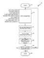
- FIG. 3is a flow diagram illustrating automatic setpoint selection process 70 performed by digital processor 22 .
- Process 70begins at start up 72 .
- Digital processor 22obtains input parameters (step 74 ), which can include, for example, a coil inductance value, a coil resistance value, flowtube gain, flowtube power rating, transmitter power rating, coil current, electrode noise, magnetic flux density, and zero shift characteristics as a function of frequency.
- the coil inductance and resistance valuescan be a result of measurements performed by digital processor 22 in conjunction with the circuitry of coil driver 24 , or may be input values applied to digital processor 22 through local operator interface 28 or communication interface 26 .
- Digital processor 22can also initiate testing to measure flowtube gain, or to prompt the operator to supply a measured gain value through local operator interface 28 or by a message sent through communication interface 26 .
- Digital processor 22may also prompt the operator to provide other parameters to use in setpoint selection, such as power rating of flowtube 10 A, and power rating of transmitter 10 B. In some cases, digital processor 22 may also prompt the operator to provide one or more of coil current, electrode noise, signal-to-noise ratio, and electrode voltage zero shift characteristics. Other parameters can also be obtained by measurement or operator input if needed in order to make use of particular criteria selections.
- Digital processor 22will prompt the operator to provide a criteria selection (step 76 ) that will be used in the automatic setpoint determination (step 78 ).
- criteria selectionsmay involve a choice of fastest response, highest signal-to-noise ratio for a particular frequency or for a particular desired accuracy, power efficiency based upon a particular desired signal-to-noise ratio, etc.
- the criteria selectionmay also include an option of continuous setpoint adjustment in background during operation of transmitter 10 or, alternatively, selection of an operating point to be used without continuous adjustment until the operator requests a new setpoint selection.
- digital processor 22calculates a selected setpoint for the coil drive frequency, current, and duty cycle (step 78 ). Digital processor 22 then sets the operating point coil frequency value, current value, and duty cycle value to be applied by coil drive 24 (step 80 ).
- Digital processor 22then checks whether the operator has chosen continuous adjustment in background (step 82 ). If the answer is no, then the automatic setpoint selection process is done (step 84 ). In that case, process 70 will not be repeated until the operator provides an input to digital processor 22 requesting a new setpoint selection. Process 70 can also be configured to restart each time transmitter 10 B powers up following a period when it has been powered down.
- Process 70returns to step 74 , and steps 74 - 82 are repeated.
- the automatic setpoint selectionallows flowmeter 10 to take into account the characteristics of both flowtube 10 A and transmitter 10 B when determining an operating point for a given installation.
- the automatic setpoint selectioncan be achieved without adding additional operating overhead or adding sophisticated signal processing. Dramatic improvement in performance of some installations can be achieved by better matching the parameters of flowtube and transmitter with the particular performance criteria desired by the operator.
- the automatic setpoint selectionallows transmitter 10 B the capability of better matching this operation with flowtubes that were not in existence at the time transmitter 10 B was manufactured.
- the automatic setpoint selectioncan adjust coil current amplitude, coil current frequency, coil current duty cycle, or any combination of those parameters based on coil inductance, coil resistance, as well as a number of other parameters such as flowtube gain, signal-to-noise ratio data, power ratings of the transmitter and flowtube, current stability and electrode characteristics.
- the coil drive operating setpointis not dependent on sensor data known at the time of transmitter manufacture. It can be continually adjusted if desired to account for changing temperatures that can affect coil resistance.
- the automatic setpoint selectionsimplifies configuration of the flowmeter for the operator, because it allows the operator to select the particular criteria to be used, and then digital processor automatically selects the setpoint based upon the characteristics of the flowmeter and the performance criteria chosen by the operator.
Landscapes
- Physics & Mathematics (AREA)
- Fluid Mechanics (AREA)
- General Physics & Mathematics (AREA)
- Electromagnetism (AREA)
- Measuring Volume Flow (AREA)
Abstract
Description
Claims (25)
Priority Applications (6)
| Application Number | Priority Date | Filing Date | Title |
|---|---|---|---|
| US14/136,955US10641627B2 (en) | 2013-12-20 | 2013-12-20 | Magnetic flowmeter with automatic operating setpoint selection |
| EP14870970.2AEP3084362B1 (en) | 2013-12-20 | 2014-08-14 | Magnetic flowmeter with automatic operating setpoint selection |
| JP2016539986AJP6457531B2 (en) | 2013-12-20 | 2014-08-14 | Electromagnetic flow meter with automatic operation setpoint selection function |
| PCT/US2014/051075WO2015094419A1 (en) | 2013-12-20 | 2014-08-14 | Magnetic flowmeter with automatic operating setpoint selection |
| CN201420499620.XUCN204142302U (en) | 2013-12-20 | 2014-09-01 | Magnetic flowmeter and transmitter |
| CN201410441382.1ACN104729594B (en) | 2013-12-20 | 2014-09-01 | The magnetic flowmeter of operational set-points can be automatically selected |
Applications Claiming Priority (1)
| Application Number | Priority Date | Filing Date | Title |
|---|---|---|---|
| US14/136,955US10641627B2 (en) | 2013-12-20 | 2013-12-20 | Magnetic flowmeter with automatic operating setpoint selection |
Publications (2)
| Publication Number | Publication Date |
|---|---|
| US20150177035A1 US20150177035A1 (en) | 2015-06-25 |
| US10641627B2true US10641627B2 (en) | 2020-05-05 |
Family
ID=52418982
Family Applications (1)
| Application Number | Title | Priority Date | Filing Date |
|---|---|---|---|
| US14/136,955Active2038-08-13US10641627B2 (en) | 2013-12-20 | 2013-12-20 | Magnetic flowmeter with automatic operating setpoint selection |
Country Status (5)
| Country | Link |
|---|---|
| US (1) | US10641627B2 (en) |
| EP (1) | EP3084362B1 (en) |
| JP (1) | JP6457531B2 (en) |
| CN (2) | CN204142302U (en) |
| WO (1) | WO2015094419A1 (en) |
Families Citing this family (13)
| Publication number | Priority date | Publication date | Assignee | Title |
|---|---|---|---|---|
| DE102014007426B4 (en)* | 2013-07-01 | 2022-07-07 | Krohne Messtechnik Gmbh | Electromagnetic flow measuring device and method for operating a magnetic inductive flow measuring device |
| US10641627B2 (en) | 2013-12-20 | 2020-05-05 | Rosemount Inc. | Magnetic flowmeter with automatic operating setpoint selection |
| US9810559B2 (en)* | 2015-03-16 | 2017-11-07 | Invensys Systems, Inc. | Systems and methods for detecting leaks in an electromagnetic flowmeter |
| DE102015116771B4 (en)* | 2015-10-02 | 2021-07-01 | Krohne Messtechnik Gmbh | Method for setting a constant magnetic field strength of a magnetic field in a magneto-inductive flow measuring device and related magneto-inductive flow measuring device |
| US10386214B2 (en)* | 2015-11-30 | 2019-08-20 | Analog Devices Global | Electromagnetic flow sensor interface allowing dc coupling |
| US9664547B1 (en)* | 2016-01-05 | 2017-05-30 | Medtronic Xomed, Inc. | Flow management system |
| DE102016211577A1 (en)* | 2016-06-28 | 2017-12-28 | Siemens Aktiengesellschaft | Magnetic-inductive flowmeter |
| JP6739616B2 (en)* | 2016-07-20 | 2020-08-12 | マイクロ モーション インコーポレイテッド | Method for Performing Temperature Compensation for Maximum Sensor Current and Test Tone Amplitude During Meter Verification |
| US11204267B2 (en) | 2019-09-05 | 2021-12-21 | Micro Motion, Inc. | Continuously adaptive digital coil driver for magnetic flowmeter |
| US11204268B2 (en)* | 2019-09-05 | 2021-12-21 | Micro Motion, Inc. | Magnetic flowmeter having a programmable bi-directional current generator |
| US11333537B2 (en) | 2019-09-05 | 2022-05-17 | Micro Motion, Inc. | Load leveling boost supply for magnetic flowmeter |
| US11181404B2 (en) | 2019-09-05 | 2021-11-23 | Micro Motion, Inc. | Magnetic flowmeter with a current sampling circuit sampling coil current pulses at a sampling frequency |
| DE102019133462A1 (en)* | 2019-12-06 | 2021-06-10 | Endress+Hauser Flowtec Ag | Method for operating a magneto-inductive flow meter and magneto-inductive flow meter |
Citations (37)
| Publication number | Priority date | Publication date | Assignee | Title |
|---|---|---|---|---|
| US3002383A (en)* | 1956-12-28 | 1961-10-03 | Mittelmann Eugene | Electromagnetic induction flowmeter |
| US3006188A (en)* | 1954-09-14 | 1961-10-31 | Foxboro Co | Magnetic flowmeter system |
| US3101615A (en)* | 1960-02-02 | 1963-08-27 | Dresser Ind | Flowmeter |
| US3977246A (en)* | 1974-06-28 | 1976-08-31 | Hokushin Electric Works, Ltd. | Magnetic flowmeter having in phase noise compensation |
| US3996797A (en)* | 1975-01-24 | 1976-12-14 | Hokushin Electric Works, Ltd. | Magnetic flowmeter |
| US4019385A (en)* | 1974-10-30 | 1977-04-26 | Hokushin Electric Works, Ltd. | Noise compensation in electromagnetic flowmeter |
| US4651286A (en) | 1983-06-23 | 1987-03-17 | Yokogawa Hokushin Electric Corporation | Electromagnetic flowmeter |
| US4658653A (en) | 1984-12-28 | 1987-04-21 | Kabushiki Kaisha Toshiba | Electromagnetic flowmeter |
| US4663976A (en)* | 1985-07-04 | 1987-05-12 | Yokogawa Hokushin Electric Corporation | Electromagnetic flowmeter |
| US5090250A (en)* | 1989-09-07 | 1992-02-25 | Kabushiki Kaisha Toshiba | Electromagnetic flowmeter utilizing magnetic fields of a plurality of frequencies |
| US5133644A (en)* | 1991-01-17 | 1992-07-28 | Halliburton Company | Multi-pressure compensation of variable displacement pump |
| JPH04318424A (en) | 1991-04-18 | 1992-11-10 | Toshiba Corp | Electromagnetic flowmeter |
| JPH06137889A (en) | 1992-10-22 | 1994-05-20 | Yamatake Honeywell Co Ltd | Spike noise filter |
| JPH07324959A (en) | 1994-06-01 | 1995-12-12 | Yamatake Honeywell Co Ltd | Electromagnetic flow meter |
| JPH08105774A (en) | 1994-10-03 | 1996-04-23 | Yamatake Honeywell Co Ltd | Electromagnetic flow meter |
| US5621177A (en) | 1995-03-02 | 1997-04-15 | Yokogawa Electric Corporation | Electromagnetic flowmeter |
| US6237424B1 (en) | 1997-04-25 | 2001-05-29 | Abb Metering Limited | Electromagnetic flowmeter having low power consumption |
| JP2002340638A (en) | 2001-05-14 | 2002-11-27 | Yokogawa Electric Corp | Electromagnetic flow meter |
| JP2004325208A (en) | 2003-04-24 | 2004-11-18 | Yokogawa Electric Corp | Electromagnetic flow meter |
| US20060095217A1 (en)* | 2004-11-01 | 2006-05-04 | Rosemount Inc. | Magnetic flowmeter with built-in simulator |
| US7197408B2 (en) | 2004-01-29 | 2007-03-27 | Invensys Systems, Inc. | Flowmeter specification and ordering system |
| WO2008042290A2 (en) | 2006-09-29 | 2008-04-10 | Rosemount Inc. | Magnetic flowmeter with verification |
| CN101263367A (en) | 2005-07-05 | 2008-09-10 | 恩德斯+豪斯流量技术股份有限公司 | Method for determining the operating point of a magneto-inductive flowmeter |
| US20080282766A1 (en)* | 2007-03-13 | 2008-11-20 | Yokogawa Electric Corporation | Electromagnetic flowmeter and zero point measurement method thereof |
| US20090015236A1 (en)* | 2007-07-10 | 2009-01-15 | Foss Scot R | Noise diagnosis of operating conditions for an electromagnetic flowmeter |
| WO2009154110A1 (en) | 2008-06-20 | 2009-12-23 | 株式会社キーエンス | Electromagnetic flow meter, electromagnetic flow measurement system, converter for electromagnetic flow meter |
| US20100024568A1 (en)* | 2008-07-29 | 2010-02-04 | Rosemount Inc. | High pressure magnetic flowmeter with stress resistant electrode assembly |
| CN101688798A (en) | 2007-04-19 | 2010-03-31 | 罗斯蒙德公司 | Output verification for magnetic flowmeters |
| CN102203569A (en) | 2008-11-03 | 2011-09-28 | 罗斯蒙德公司 | Flow disturbance compensation for magnetic flowmeter |
| CN102365530A (en) | 2009-05-04 | 2012-02-29 | 罗斯蒙德公司 | Magnetic flowmeter for measuring flow |
| CN102388532A (en)* | 2009-01-02 | 2012-03-21 | 罗伯特·博世有限公司 | Method for operating a brushless DC motor |
| CN102410847A (en) | 2010-08-11 | 2012-04-11 | 罗斯蒙德公司 | Noise detection and avoidance |
| CN102853869A (en) | 2011-06-28 | 2013-01-02 | 罗斯蒙德公司 | Variable frequency magnetic flowmeter |
| US20130201316A1 (en)* | 2012-01-09 | 2013-08-08 | May Patents Ltd. | System and method for server based control |
| CN203349879U (en) | 2013-03-14 | 2013-12-18 | 罗斯蒙德公司 | Magnetic flow meter with connecting PTFE (Polytetrafluoroethylene) electrodes |
| US20140083199A1 (en)* | 2012-09-26 | 2014-03-27 | Rosemount Inc. | Magnetic flowmeter with multiple coils |
| CN204142302U (en) | 2013-12-20 | 2015-02-04 | 罗斯蒙特公司 | Magnetic flowmeter and transmitter |
- 2013
- 2013-12-20USUS14/136,955patent/US10641627B2/enactiveActive
- 2014
- 2014-08-14JPJP2016539986Apatent/JP6457531B2/enactiveActive
- 2014-08-14EPEP14870970.2Apatent/EP3084362B1/enactiveActive
- 2014-08-14WOPCT/US2014/051075patent/WO2015094419A1/enactiveApplication Filing
- 2014-09-01CNCN201420499620.XUpatent/CN204142302U/ennot_activeExpired - Lifetime
- 2014-09-01CNCN201410441382.1Apatent/CN104729594B/enactiveActive
Patent Citations (44)
| Publication number | Priority date | Publication date | Assignee | Title |
|---|---|---|---|---|
| US3006188A (en)* | 1954-09-14 | 1961-10-31 | Foxboro Co | Magnetic flowmeter system |
| US3002383A (en)* | 1956-12-28 | 1961-10-03 | Mittelmann Eugene | Electromagnetic induction flowmeter |
| US3101615A (en)* | 1960-02-02 | 1963-08-27 | Dresser Ind | Flowmeter |
| US3977246A (en)* | 1974-06-28 | 1976-08-31 | Hokushin Electric Works, Ltd. | Magnetic flowmeter having in phase noise compensation |
| US4019385A (en)* | 1974-10-30 | 1977-04-26 | Hokushin Electric Works, Ltd. | Noise compensation in electromagnetic flowmeter |
| US3996797A (en)* | 1975-01-24 | 1976-12-14 | Hokushin Electric Works, Ltd. | Magnetic flowmeter |
| US4651286A (en) | 1983-06-23 | 1987-03-17 | Yokogawa Hokushin Electric Corporation | Electromagnetic flowmeter |
| US4658653A (en) | 1984-12-28 | 1987-04-21 | Kabushiki Kaisha Toshiba | Electromagnetic flowmeter |
| US4663976A (en)* | 1985-07-04 | 1987-05-12 | Yokogawa Hokushin Electric Corporation | Electromagnetic flowmeter |
| US5090250A (en)* | 1989-09-07 | 1992-02-25 | Kabushiki Kaisha Toshiba | Electromagnetic flowmeter utilizing magnetic fields of a plurality of frequencies |
| US5133644A (en)* | 1991-01-17 | 1992-07-28 | Halliburton Company | Multi-pressure compensation of variable displacement pump |
| JPH04318424A (en) | 1991-04-18 | 1992-11-10 | Toshiba Corp | Electromagnetic flowmeter |
| JPH06137889A (en) | 1992-10-22 | 1994-05-20 | Yamatake Honeywell Co Ltd | Spike noise filter |
| JPH07324959A (en) | 1994-06-01 | 1995-12-12 | Yamatake Honeywell Co Ltd | Electromagnetic flow meter |
| JPH08105774A (en) | 1994-10-03 | 1996-04-23 | Yamatake Honeywell Co Ltd | Electromagnetic flow meter |
| US5621177A (en) | 1995-03-02 | 1997-04-15 | Yokogawa Electric Corporation | Electromagnetic flowmeter |
| US6237424B1 (en) | 1997-04-25 | 2001-05-29 | Abb Metering Limited | Electromagnetic flowmeter having low power consumption |
| JP2002340638A (en) | 2001-05-14 | 2002-11-27 | Yokogawa Electric Corp | Electromagnetic flow meter |
| JP2004325208A (en) | 2003-04-24 | 2004-11-18 | Yokogawa Electric Corp | Electromagnetic flow meter |
| US7197408B2 (en) | 2004-01-29 | 2007-03-27 | Invensys Systems, Inc. | Flowmeter specification and ordering system |
| US7516023B2 (en) | 2004-01-29 | 2009-04-07 | Invensys Systems, Inc. | Flowmeter specification and ordering system |
| US20060095217A1 (en)* | 2004-11-01 | 2006-05-04 | Rosemount Inc. | Magnetic flowmeter with built-in simulator |
| CN101263367A (en) | 2005-07-05 | 2008-09-10 | 恩德斯+豪斯流量技术股份有限公司 | Method for determining the operating point of a magneto-inductive flowmeter |
| WO2008042290A3 (en) | 2006-09-29 | 2008-07-24 | Rosemount Inc | Magnetic flowmeter with verification |
| WO2008042290A2 (en) | 2006-09-29 | 2008-04-10 | Rosemount Inc. | Magnetic flowmeter with verification |
| US20080282766A1 (en)* | 2007-03-13 | 2008-11-20 | Yokogawa Electric Corporation | Electromagnetic flowmeter and zero point measurement method thereof |
| CN101688798A (en) | 2007-04-19 | 2010-03-31 | 罗斯蒙德公司 | Output verification for magnetic flowmeters |
| US20090015236A1 (en)* | 2007-07-10 | 2009-01-15 | Foss Scot R | Noise diagnosis of operating conditions for an electromagnetic flowmeter |
| WO2009008974A1 (en) | 2007-07-10 | 2009-01-15 | Rosemount Inc. | Noise diagnosis of operating conditions for an electromagnetic flowmeter |
| US7688057B2 (en) | 2007-07-10 | 2010-03-30 | Rosemount Inc. | Noise diagnosis of operating conditions for an electromagnetic flowmeter |
| JP2010533295A (en) | 2007-07-10 | 2010-10-21 | ローズマウント インコーポレイテッド | Noise diagnosis of electromagnetic flow meter operating conditions |
| WO2009154110A1 (en) | 2008-06-20 | 2009-12-23 | 株式会社キーエンス | Electromagnetic flow meter, electromagnetic flow measurement system, converter for electromagnetic flow meter |
| US20100024568A1 (en)* | 2008-07-29 | 2010-02-04 | Rosemount Inc. | High pressure magnetic flowmeter with stress resistant electrode assembly |
| CN102105766A (en) | 2008-07-29 | 2011-06-22 | 罗斯蒙德公司 | High pressure magnetic flowmeter with stress resistant electrode assembly |
| CN102203569A (en) | 2008-11-03 | 2011-09-28 | 罗斯蒙德公司 | Flow disturbance compensation for magnetic flowmeter |
| CN102388532A (en)* | 2009-01-02 | 2012-03-21 | 罗伯特·博世有限公司 | Method for operating a brushless DC motor |
| CN102365530A (en) | 2009-05-04 | 2012-02-29 | 罗斯蒙德公司 | Magnetic flowmeter for measuring flow |
| JP2012526279A (en) | 2009-05-04 | 2012-10-25 | ローズマウント インコーポレイテッド | Electromagnetic flow meter for flow velocity measurement |
| CN102410847A (en) | 2010-08-11 | 2012-04-11 | 罗斯蒙德公司 | Noise detection and avoidance |
| CN102853869A (en) | 2011-06-28 | 2013-01-02 | 罗斯蒙德公司 | Variable frequency magnetic flowmeter |
| US20130201316A1 (en)* | 2012-01-09 | 2013-08-08 | May Patents Ltd. | System and method for server based control |
| US20140083199A1 (en)* | 2012-09-26 | 2014-03-27 | Rosemount Inc. | Magnetic flowmeter with multiple coils |
| CN203349879U (en) | 2013-03-14 | 2013-12-18 | 罗斯蒙德公司 | Magnetic flow meter with connecting PTFE (Polytetrafluoroethylene) electrodes |
| CN204142302U (en) | 2013-12-20 | 2015-02-04 | 罗斯蒙特公司 | Magnetic flowmeter and transmitter |
Non-Patent Citations (5)
| Title |
|---|
| Extended European Search Report dated Dec. 12, 2019, received for corresponding European Application No. 14870970.2, 6 pages. |
| First Chinese Office Action dated Jul. 2, 2018, for corresponding Chinese Application No. 201410441382.1. |
| First Japanese Office Action, for Japanese Patent Application No. 2016-539986, dated Mar. 28, 2018, 7 pages. |
| International Preliminary Report on Patentability for PCT/US2014/051075, dated Jun. 21, 2016, 6 pages. |
| International Search Report and Written Opinion, dated Nov. 26, 2014, for PCT Application No. PCT/US2014/051075, 9 pages. |
Also Published As
| Publication number | Publication date |
|---|---|
| CN104729594B (en) | 2019-11-12 |
| US20150177035A1 (en) | 2015-06-25 |
| EP3084362A4 (en) | 2017-08-09 |
| EP3084362A1 (en) | 2016-10-26 |
| CN104729594A (en) | 2015-06-24 |
| CN204142302U (en) | 2015-02-04 |
| EP3084362B1 (en) | 2021-03-17 |
| WO2015094419A1 (en) | 2015-06-25 |
| JP6457531B2 (en) | 2019-01-23 |
| JP2016540985A (en) | 2016-12-28 |
Similar Documents
| Publication | Publication Date | Title |
|---|---|---|
| US10641627B2 (en) | Magnetic flowmeter with automatic operating setpoint selection | |
| US9696188B2 (en) | Magnetic flowmeter with automatic adjustment based on sensed complex impedance | |
| EP2726826B1 (en) | Variable frequency magnetic flowmeter | |
| US10663331B2 (en) | Magnetic flowmeter with power limit and over-current detection | |
| US5639970A (en) | Current selection circuitry for magnetic flowmeter | |
| EP3120116B1 (en) | Magnetic core configuration for magnetic flowmeters | |
| EP4025882B1 (en) | Continuously adaptive digital coil driver for magnetic flowmeter | |
| EP4025881B1 (en) | Magnetic flowmeter having a programmable bi-directional current generator | |
| KR102616224B1 (en) | Flowmeter resistant to environmental changes and flow measurement method | |
| WO2021045930A1 (en) | Magnetic flowmeter having a programmable bi-directional current generator |
Legal Events
| Date | Code | Title | Description |
|---|---|---|---|
| AS | Assignment | Owner name:ROSEMOUNT INC., MINNESOTA Free format text:ASSIGNMENT OF ASSIGNORS INTEREST;ASSIGNORS:ROVNER, BRUCE D.;FOSS, SCOT RONALD;ROGERS, STEVEN B.;REEL/FRAME:035074/0470 Effective date:20140107 | |
| AS | Assignment | Owner name:MICRO MOTION, INC., COLORADO Free format text:ASSIGNMENT OF ASSIGNORS INTEREST;ASSIGNOR:ROSEMOUNT INC.;REEL/FRAME:038879/0810 Effective date:20160415 | |
| STCV | Information on status: appeal procedure | Free format text:NOTICE OF APPEAL FILED | |
| STCV | Information on status: appeal procedure | Free format text:APPEAL BRIEF (OR SUPPLEMENTAL BRIEF) ENTERED AND FORWARDED TO EXAMINER | |
| STPP | Information on status: patent application and granting procedure in general | Free format text:NON FINAL ACTION MAILED | |
| STPP | Information on status: patent application and granting procedure in general | Free format text:RESPONSE TO NON-FINAL OFFICE ACTION ENTERED AND FORWARDED TO EXAMINER | |
| STPP | Information on status: patent application and granting procedure in general | Free format text:NOTICE OF ALLOWANCE MAILED -- APPLICATION RECEIVED IN OFFICE OF PUBLICATIONS | |
| STCF | Information on status: patent grant | Free format text:PATENTED CASE | |
| MAFP | Maintenance fee payment | Free format text:PAYMENT OF MAINTENANCE FEE, 4TH YEAR, LARGE ENTITY (ORIGINAL EVENT CODE: M1551); ENTITY STATUS OF PATENT OWNER: LARGE ENTITY Year of fee payment:4 |