US10640878B2 - Ozone generator for a faucet - Google Patents
Ozone generator for a faucetDownload PDFInfo
- Publication number
- US10640878B2 US10640878B2US15/336,048US201615336048AUS10640878B2US 10640878 B2US10640878 B2US 10640878B2US 201615336048 AUS201615336048 AUS 201615336048AUS 10640878 B2US10640878 B2US 10640878B2
- Authority
- US
- United States
- Prior art keywords
- ozone generator
- housing
- valve
- current spreader
- anode
- Prior art date
- Legal status (The legal status is an assumption and is not a legal conclusion. Google has not performed a legal analysis and makes no representation as to the accuracy of the status listed.)
- Active, expires
Links
- CBENFWSGALASAD-UHFFFAOYSA-NOzoneChemical compound[O-][O+]=OCBENFWSGALASAD-UHFFFAOYSA-N0.000titleclaimsdescription158
- XLYOFNOQVPJJNP-UHFFFAOYSA-NwaterSubstancesOXLYOFNOQVPJJNP-UHFFFAOYSA-N0.000claimsdescription142
- 238000004891communicationMethods0.000claimsdescription41
- 239000012530fluidSubstances0.000claimsdescription31
- 238000007789sealingMethods0.000claimsdescription12
- 239000012528membraneSubstances0.000claimsdescription9
- 239000011248coating agentSubstances0.000claimsdescription8
- 238000000576coating methodMethods0.000claimsdescription8
- 229910003460diamondInorganic materials0.000claimsdescription6
- 239000010432diamondSubstances0.000claimsdescription6
- 238000010276constructionMethods0.000claimsdescription4
- 230000004913activationEffects0.000claimsdescription3
- 238000000708deep reactive-ion etchingMethods0.000claimsdescription3
- 229910052710siliconInorganic materials0.000claimsdescription3
- 239000010703siliconSubstances0.000claimsdescription3
- 239000005518polymer electrolyteSubstances0.000claimsdescription2
- 239000007787solidSubstances0.000claimsdescription2
- 239000000463materialSubstances0.000description7
- -1polytetrafluoroethylenePolymers0.000description7
- 238000013461designMethods0.000description6
- 239000001257hydrogenSubstances0.000description5
- 229910052739hydrogenInorganic materials0.000description5
- 238000000034methodMethods0.000description5
- 239000001301oxygenSubstances0.000description5
- 229910052760oxygenInorganic materials0.000description5
- 229920000642polymerPolymers0.000description5
- 239000004020conductorSubstances0.000description4
- 230000000249desinfective effectEffects0.000description4
- RYGMFSIKBFXOCR-UHFFFAOYSA-NCopperChemical compound[Cu]RYGMFSIKBFXOCR-UHFFFAOYSA-N0.000description3
- RTAQQCXQSZGOHL-UHFFFAOYSA-NTitaniumChemical compound[Ti]RTAQQCXQSZGOHL-UHFFFAOYSA-N0.000description3
- 239000010949copperSubstances0.000description3
- 229910052802copperInorganic materials0.000description3
- 239000012777electrically insulating materialSubstances0.000description3
- 239000002210silicon-based materialSubstances0.000description3
- ZOXJGFHDIHLPTG-UHFFFAOYSA-NBoronChemical compound[B]ZOXJGFHDIHLPTG-UHFFFAOYSA-N0.000description2
- QVGXLLKOCUKJST-UHFFFAOYSA-Natomic oxygenChemical compound[O]QVGXLLKOCUKJST-UHFFFAOYSA-N0.000description2
- 230000004888barrier functionEffects0.000description2
- 230000008901benefitEffects0.000description2
- 229910052796boronInorganic materials0.000description2
- 238000005229chemical vapour depositionMethods0.000description2
- 238000009792diffusion processMethods0.000description2
- 238000005868electrolysis reactionMethods0.000description2
- 239000008151electrolyte solutionSubstances0.000description2
- UQSQSQZYBQSBJZ-UHFFFAOYSA-Nfluorosulfonic acidChemical compoundOS(F)(=O)=OUQSQSQZYBQSBJZ-UHFFFAOYSA-N0.000description2
- 150000002431hydrogenChemical class0.000description2
- 239000004033plasticSubstances0.000description2
- 229920003023plasticPolymers0.000description2
- 229920002492poly(sulfone)Polymers0.000description2
- 229920001343polytetrafluoroethylenePolymers0.000description2
- 239000004810polytetrafluoroethyleneSubstances0.000description2
- 230000008569processEffects0.000description2
- 230000004044responseEffects0.000description2
- 238000003860storageMethods0.000description2
- 239000010936titaniumSubstances0.000description2
- 229910052719titaniumInorganic materials0.000description2
- 241000894006BacteriaSpecies0.000description1
- 239000004593EpoxySubstances0.000description1
- 229920000557Nafion®Polymers0.000description1
- XUIMIQQOPSSXEZ-UHFFFAOYSA-NSiliconChemical compound[Si]XUIMIQQOPSSXEZ-UHFFFAOYSA-N0.000description1
- 238000009825accumulationMethods0.000description1
- 230000006978adaptationEffects0.000description1
- WYTGDNHDOZPMIW-RCBQFDQVSA-NalstonineNatural productsC1=CC2=C3C=CC=CC3=NC2=C2N1C[C@H]1[C@H](C)OC=C(C(=O)OC)[C@H]1C2WYTGDNHDOZPMIW-RCBQFDQVSA-N0.000description1
- 230000009286beneficial effectEffects0.000description1
- 239000006229carbon blackSubstances0.000description1
- 230000015556catabolic processEffects0.000description1
- 239000012459cleaning agentSubstances0.000description1
- 230000006835compressionEffects0.000description1
- 238000007906compressionMethods0.000description1
- 229920001577copolymerPolymers0.000description1
- 238000006731degradation reactionMethods0.000description1
- 230000018044dehydrationEffects0.000description1
- 238000006297dehydration reactionMethods0.000description1
- 238000000151depositionMethods0.000description1
- 239000000645desinfectantSubstances0.000description1
- 238000009826distributionMethods0.000description1
- 239000003651drinking waterSubstances0.000description1
- 235000020188drinking waterNutrition0.000description1
- 239000013505freshwaterSubstances0.000description1
- 239000007789gasSubstances0.000description1
- 230000036571hydrationEffects0.000description1
- 238000006703hydration reactionMethods0.000description1
- 230000003116impacting effectEffects0.000description1
- 150000002500ionsChemical class0.000description1
- 238000004519manufacturing processMethods0.000description1
- 238000005259measurementMethods0.000description1
- 238000000465mouldingMethods0.000description1
- 244000052769pathogenSpecies0.000description1
- 230000010287polarizationEffects0.000description1
- 230000008439repair processEffects0.000description1
- 238000012546transferMethods0.000description1
- 230000007704transitionEffects0.000description1
- 238000011144upstream manufacturingMethods0.000description1
Images


Classifications
- C—CHEMISTRY; METALLURGY
- C25—ELECTROLYTIC OR ELECTROPHORETIC PROCESSES; APPARATUS THEREFOR
- C25B—ELECTROLYTIC OR ELECTROPHORETIC PROCESSES FOR THE PRODUCTION OF COMPOUNDS OR NON-METALS; APPARATUS THEREFOR
- C25B15/00—Operating or servicing cells
- C25B15/08—Supplying or removing reactants or electrolytes; Regeneration of electrolytes
- C—CHEMISTRY; METALLURGY
- C25—ELECTROLYTIC OR ELECTROPHORETIC PROCESSES; APPARATUS THEREFOR
- C25B—ELECTROLYTIC OR ELECTROPHORETIC PROCESSES FOR THE PRODUCTION OF COMPOUNDS OR NON-METALS; APPARATUS THEREFOR
- C25B1/00—Electrolytic production of inorganic compounds or non-metals
- C25B1/01—Products
- C25B1/13—Ozone
- C—CHEMISTRY; METALLURGY
- C25—ELECTROLYTIC OR ELECTROPHORETIC PROCESSES; APPARATUS THEREFOR
- C25B—ELECTROLYTIC OR ELECTROPHORETIC PROCESSES FOR THE PRODUCTION OF COMPOUNDS OR NON-METALS; APPARATUS THEREFOR
- C25B11/00—Electrodes; Manufacture thereof not otherwise provided for
- C25B11/02—Electrodes; Manufacture thereof not otherwise provided for characterised by shape or form
- C25B11/03—Electrodes; Manufacture thereof not otherwise provided for characterised by shape or form perforated or foraminous
- C—CHEMISTRY; METALLURGY
- C25—ELECTROLYTIC OR ELECTROPHORETIC PROCESSES; APPARATUS THEREFOR
- C25B—ELECTROLYTIC OR ELECTROPHORETIC PROCESSES FOR THE PRODUCTION OF COMPOUNDS OR NON-METALS; APPARATUS THEREFOR
- C25B15/00—Operating or servicing cells
- C25B15/02—Process control or regulation
- C25B9/08—
- C25B9/10—
- C—CHEMISTRY; METALLURGY
- C25—ELECTROLYTIC OR ELECTROPHORETIC PROCESSES; APPARATUS THEREFOR
- C25B—ELECTROLYTIC OR ELECTROPHORETIC PROCESSES FOR THE PRODUCTION OF COMPOUNDS OR NON-METALS; APPARATUS THEREFOR
- C25B9/00—Cells or assemblies of cells; Constructional parts of cells; Assemblies of constructional parts, e.g. electrode-diaphragm assemblies; Process-related cell features
- C25B9/17—Cells comprising dimensionally-stable non-movable electrodes; Assemblies of constructional parts thereof
- C25B9/19—Cells comprising dimensionally-stable non-movable electrodes; Assemblies of constructional parts thereof with diaphragms
- C25B9/23—Cells comprising dimensionally-stable non-movable electrodes; Assemblies of constructional parts thereof with diaphragms comprising ion-exchange membranes in or on which electrode material is embedded
- Y—GENERAL TAGGING OF NEW TECHNOLOGICAL DEVELOPMENTS; GENERAL TAGGING OF CROSS-SECTIONAL TECHNOLOGIES SPANNING OVER SEVERAL SECTIONS OF THE IPC; TECHNICAL SUBJECTS COVERED BY FORMER USPC CROSS-REFERENCE ART COLLECTIONS [XRACs] AND DIGESTS
- Y02—TECHNOLOGIES OR APPLICATIONS FOR MITIGATION OR ADAPTATION AGAINST CLIMATE CHANGE
- Y02E—REDUCTION OF GREENHOUSE GAS [GHG] EMISSIONS, RELATED TO ENERGY GENERATION, TRANSMISSION OR DISTRIBUTION
- Y02E60/00—Enabling technologies; Technologies with a potential or indirect contribution to GHG emissions mitigation
- Y02E60/30—Hydrogen technology
- Y02E60/36—Hydrogen production from non-carbon containing sources, e.g. by water electrolysis
Definitions
- the present disclosurerelates to an ozone generator. More particularly, the present disclosure relates to an electrolytic ozone generator for use with a faucet, and to methods for assembling and using the same.
- An electrolytic ozone generatormay be used to produce ozone in water.
- the ozonemay perform a beneficial disinfecting function by destroying bacteria and pathogens in the water or surfaces it contacts.
- existing ozone generatorsare often difficult to assemble, repair, have limited life, and may suffer from low water flow or reduced dissolved ozone concentration
- the present disclosureprovides an electrolytic ozone generator for use with a faucet and to methods for assembling and using the same.
- an ozone generatorfor use with a faucet, the ozone generator including an outer cartridge and an electrolytic cell assembly received within the outer cartridge.
- the electrolytic cell assemblyincludes a first housing, an anode coupled to the first housing, a second housing, a cathode coupled to the second housing, a separator positioned between the anode and the cathode, and a holder that couples the first housing to the second housing independently of the outer cartridge.
- an ozone generatorfor use with a faucet, the ozone generator including a first housing, a first current spreader overmolded by the first housing, an anode in electrical communication with the first current spreader, a second housing, a second current spreader overmolded by the second housing, a cathode in electrical communication with the second current spreader, and a separator between the anode and the cathode.
- an ozone generator system for use with a faucetincludes a mixing valve having a cold water inlet fluidly coupled to a cold water source, a hot water inlet fluidly coupled to a hot water source, and an outlet in selective fluid communication with the cold water inlet and the hot water inlet, and a valve body having a first valve receiving chamber, a second valve receiving chamber, and an ozone generator receiving chamber, and an outlet passageway.
- the ozone generator systemfurther includes an ozone generator received within the ozone generator receiving chamber, a first electrically operable valve received within the first valve receiving chamber and configured to control water flow from the outlet of the mixing valve to the outlet passageway of the valve body, and a second electrically operably valve received within the second valve receiving chamber and configured to control water flow from the cold water source to the ozone generator.
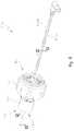
- FIG. 1is an assembled perspective view of an exemplary ozone generator of the present disclosure
- FIG. 2is a cross-sectional view of the ozone generator of FIG. 1 , taken along line 2 - 2 of FIG. 1 ;
- FIG. 3is another cross-sectional view of the ozone generator of FIG. 1 , taken along line 3 - 3 of FIG. 1 , and showing the fluid pipe;
- FIG. 4is an exploded perspective view of the ozone generator of FIG. 1 , the ozone generator including first and second housings, first and second current spreaders, first and second frames, first and second electrodes, and a separator;
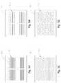
- FIGS. 5A-5Dare plan views of exemplary electrodes for use in the ozone generator of FIG. 1 ;
- FIG. 6is an exploded perspective view of the first housing, the first current spreader, the first frame, the first electrode, and the separator of FIG. 4 ;
- FIG. 7is a perspective view of the first and second housings of FIG. 4 ;
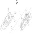
- FIG. 8is a perspective view of the first and second current spreaders of FIG. 4 ;
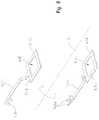
- FIG. 9is a perspective view of the first and second frames of FIG. 4 ;
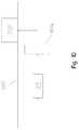
- FIG. 10is a schematic view of the ozone generator of FIG. 1 in fluid communication with a faucet.
- FIG. 11is an assembled perspective view of a further exemplary ozone generator of the present disclosure.
- FIG. 12is a cross-sectional view of the ozone generator of FIG. 11 , taken along line 12 - 12 of FIG. 11 ;
- FIG. 13is another cross-sectional view of the ozone generator of FIG. 11 , taken along line 13 - 13 of FIG. 11 ;
- FIG. 14is an exploded perspective view of the ozone generator of FIG. 11 , the ozone generator including first and second housings, first and second current spreaders, first and second frames, first and second electrodes, and a separator;
- FIG. 15is an exploded perspective view of the first housing, the first current spreader, the first frame, the first electrode, and the separator of FIG. 14 ;
- FIG. 16is a right perspective view of an illustrative system including an ozone generator of the present disclosure
- FIG. 17is left perspective view of the illustrative system of FIG. 16 ;
- FIG. 18is an exploded perspective view of the illustrative system of FIG. 17 ;
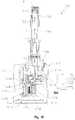
- FIG. 19is a cross-sectional view taken along line 19 - 19 of FIG. 16 ;
- FIG. 19Ais detail view of FIG. 19 , showing the cold water solenoid valve in a closed position
- FIG. 19Bis a detail view of FIG. 19 , showing the cold water solenoid valve in an open position
- FIG. 20is a cross-sectional view taken along line 20 - 20 of FIG. 16 ;
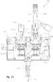
- FIG. 21is a cross-sectional view taken along line 21 - 21 of FIG. 16 ;
- FIG. 22is a cross-sectional view taken along line 22 - 22 of FIG. 16 ;
- FIG. 23is a cross-sectional view taken along line 23 - 23 of FIG. 17 ;
- FIG. 24is a cross-sectional view taken along line 24 - 24 of FIG. 16 ;
- FIG. 25is a first partially exploded perspective view of the system of FIG. 17 ;
- FIG. 26is a second partially exploded perspective view of the system of FIG. 17 ;
- FIG. 27is a side view, in partial cross-section, of the solenoid housing of FIG. 25 .
- FIGS. 1-4An exemplary ozone generator 100 of the present disclosure is shown in FIGS. 1-4 .
- the illustrative ozone generator 100has an inlet end 102 , an outlet end 104 , and a longitudinal axis L extending therebetween.
- the ozone generator 100includes an outer pipe fitting 110 , an outer cylindrical cartridge 112 , and one or more outer sealing rings 114 surrounding the cartridge 112 .
- the pipe fitting 110 and the cartridge 112define a space 116 therebetween for receiving a fluid pipe 117 ( FIG. 3 ). More particularly, the pipe fitting 110 is internally threaded to mate with externally threaded fluid pipe 117 .
- the sealing rings 114illustratively elastomeric o-rings, promote a sealed connection between the pipe fitting 110 , the cartridge 112 , and the fluid pipe 117 .
- the ozone generator 100further includes an electrolytic cell assembly 120 located inside the cartridge 112 .
- the illustrative electrolytic cell assembly 120includes a first housing or carrier 130 a and a second housing or carrier 130 b , a first current spreader 140 a and a second current spreader 140 b , a first frame 150 a and a second frame 150 a , a first electrode 160 a and a second electrode 160 b , and an electrolytic separator 170 .
- Each component of the electrolytic cell assembly 120is described further below with continued reference to FIG. 4 .
- the first and second housings 130 a , 130 b of the electrolytic cell assembly 120are compressed together with the other components of the electrolytic cell assembly 120 being mechanically and electrically sandwiched therebetween.
- one or more sealing rings 132illustratively elastomeric o-rings, are positioned around the housings 130 a , 130 b to hold the housings 130 a , 130 b together.
- Each housing 130 a , 130 bmay be generally rectangular in cross-section except for the areas of rings 132 , which may be generally semi-circular in cross-section.
- the housings 130 a , 130 bare held together by the sealing rings 132 independently of the outer cartridge 112 to facilitate storage and assembly of the electrolytic cell assembly 112 , with or without cartridge 112 in place. It is also within the scope of the present disclosure that the first and second housings 130 a , 130 b may be clamped, fastened, or otherwise held together.
- the housings 130 a , 130 bare constructed of an electrically insulating material, such as a polymer.
- An exemplary polymeris the Udel® P-1700 polysulfone material available from Solvay Plastics.
- the first and second current spreaders 140 a , 140 b of the electrolytic cell assembly 120mate with the first and second housings 130 a , 130 b , respectively.
- the first and second housings 130 a , 130 bare overmolded onto the first and second current spreaders 140 a , 140 b , respectively, to form integral, pre-assembled, water-tight, hermetically-sealed components without the need for additional seals (e.g., epoxy).
- the current spreaders 140 a , 140 bare constructed of an electrically conductive material, such as titanium or another suitable material.
- the first current spreader 140 aincludes a first terminal 142 a that extends out of the first housing 130 a in a sealed manner for electrical communication with a first wire lead 144 a .
- the first terminal 142 ais illustratively planar and supports tabs 143 a which are configured to be crimped onto the first wire lead 144 a .
- the second current spreader 140 bincludes a second terminal 142 b that extends out of the second housing 130 b in a sealed manner for electrical communication with a second wire lead 144 b .
- the second terminal 142 bis illustratively planar and supports tabs 143 b which are configured to be crimped onto the second wire lead 144 b.
- the first current spreader 140 aalso includes a first rectangular body 145 a defining a first opening 146 a that is sized and shaped to receive and expose the first electrode 160 a , as discussed further below.
- the second current spreader 140 bincludes a second rectangular body 145 b defining a second opening 146 b that is sized and shaped to receive and expose the second electrode 160 b , as discussed further below.
- the bodies 145 a and 145 bare illustratively planar wherein the openings 146 a , 146 b in the current spreaders 140 a , 140 b may be flush with the surrounding housings 130 a , 130 b .
- the first current spreader 140 amay be surrounded by the overmolded material of the first housing 130 a in a sealed manner, as shown in FIG. 3 .
- the second current spreader 140 bmay be surrounded by the overmolded material of the second housing 130 b in a sealed manner.
- the first and second frames 150 a , 150 b of the electrolytic cell assembly 120mate with the first and second housings 130 a , 130 b , respectively.
- the frames 150 a , 150 bare constructed of an electrically insulating material, such as a polymer.
- An exemplary polymeris the Udel® P-1700 polysulfone material available from Solvay Plastics.
- the first frame 150 aincludes a first scalloped opening 152 a that is sized and shaped to receive the first electrode 160 a in electrical communication with the first current spreader 140 a .
- the second frame 150 bincludes a second scalloped opening 152 b that is sized and shaped to receive the second electrode 160 b in electrical communication with the second current spreader 140 b .
- the first and second frames 150 a , 150 bmay cooperate with the first and second overmolded housings 130 a , 130 b to otherwise shield or insulate the first and second current spreaders 140 a , 140 b , respectively, to prevent electrical contact between the first and second current spreaders 140 a , 140 b.
- the first and second electrodes 160 a , 160 b of the electrolytic cell assembly 120are received within the first and second frames 150 a , 150 b , respectively.
- Each electrode 160 a , 160 bmay have a back side 162 a , 162 b that interacts with the adjacent current spreader 140 a , 140 b , respectively, and a front side 164 a , 164 b that interacts with the separator 170 .
- An exemplary electrode 160 a , 160 bis constructed of boron-doped silicon or another suitable material.
- the boron doped silicon materialserves as a conductor to pass current between the current spreader and boron doped,
- the depoed silicon materialmay be about 200-800 microns thick, such as about 500 microns thick.
- the front side 164 a , 164 b of each electrode 160 a , 160 bmay have a boron-doped diamond coating or another suitable coating.
- the coatingmay be about 2-10 microns thick.
- the coatingmay be applied to the underlying silicon material by chemical vapor deposition (CVD) or another suitable deposition technique.
- the illustrative electrodes 160 a , 160 bare generally rectangular in shape, having a width of about 8 millimeters and a length of about 10 millimeters, although the size and shape of the electrodes 160 a , 160 b may vary.
- each electrode 160 a , 160 bcommunicate with the water flowing through the electrolytic cell assembly 120 .
- Each electrode 160 a , 160 bmay include a plurality of water passageways 166 (e.g., slots) to increase the exposed surface area of each electrode 160 a , 160 b for communication with water and to allow water flow through each electrode 160 a , 160 b .
- the water passageways 166may be formed using deep reactive ion etching (DRIE) or another suitable technique.
- DRIEdeep reactive ion etching
- Electrode 160 - 160 ′′′having different configurations of water passageways 166 - 166 ′′′ are shown in FIGS. 5A-5D .
- the electrode 160includes a relatively large number of (specifically 34) straight water passageways 166 .
- Electrode 160may be referenced as having a “fine” design.
- the electrode 160 ′includes a relatively small number of (specifically 22) straight water passageways 166 ′.
- Electrode 160 ′may be referenced as having a “sparse” design.
- FIG. 5Athe electrode 160 includes a relatively large number of (specifically 34) straight water passageways 166 .
- Electrode 160may be referenced as having a “fine” design.
- the electrode 160 ′includes a relatively small number of (specifically 22) straight water passageways 166 ′.
- Electrode 160 ′may be referenced as having a “sparse” design.
- FIG. 5Athe electrode 160 includes a relatively large number of (specifically 34) straight water passage
- the electrode 160 ′′includes an intermediate number of (specifically 26) water passageways 166 ′′ that vary in width repeatedly across their length from a widened bulbous shape to a narrowed straight shape. Electrode 160 ′′ may be referenced as having a “knotted” design. In FIG. 5D , the electrode 160 ′′′ includes a relatively small number of (specifically 22) water passageways 166 ′′′ that deviate side-to-side in a zig-zag or wave-like pattern across their length. Electrode 160 ′′′ may be referenced as a “serpentine” design.
- the separator 170 of the electrolytic cell assembly 120is positioned between the first and second electrodes 160 a , 160 b .
- the separator 170is a proton exchange membrane (PEM) designed to conduct protons between the electrodes 160 a , 160 b .
- the separator 170may be constructed of a solid polymer electrolyte (SPE) membrane.
- An exemplary SPE membraneis a polytetrafluoroethylene (PTFE)/perfluorosulfonic acid (PFSA) copolymer membrane, which is commercially available from DuPontTM as a Nafion® membrane. Because pressures on the separator 170 are balanced, the separator 170 may be a thin, cast film.
- the thin separator 170may allow for some cross-diffusion of water, hydrogen, and/or oxygen without negatively impacting the performance of the electrolytic cell assembly 120 . In fact, such diffusion may promote efficiency and output by reducing polarization voltage associated with dehydration and reducing bulk ion resistance.
- An exemplary separator 170may be about 20-30 microns thick, such as about 25 microns thick.
- the components of the electrolytic cell assembly 120may include registration features to facilitate the assembly process and, once assembled, to produce stable mechanical connections between the components.
- the first housing 130 amay include one or more posts 180 that register with corresponding holes 182 in the second housing 130 b .
- the first frame 150 amay include one or more posts 190 that register with corresponding holes 192 in the separator 170 , corresponding notches 194 in the second frame 150 b , and corresponding holes 196 in both housings 130 a , 130 b
- the outer perimeter of the electrodes 160 a , 160 bmay be smaller than the area defined by the posts 190 in the frames 150 a , 150 b to avoid the need for forming corresponding registration holes in the electrodes 160 a , 160 b , which could risk damage to the fragile electrodes 160 a , 160 b and reduce the active area of the electrodes 160 a , 160 b.
- Corresponding components of the electrolytic cell assembly 120may be identical in construction and rotated into the desired orientation.
- the same housing componentmay be placed in a first orientation for use as the first housing 130 a or rotated 180 degrees about the longitudinal axis L for use as the second housing 130 b .
- the housing componentmay have opposite registration features located on opposite sides of the longitudinal axis L such that, when rotated, the registration posts 180 on the first housing 130 a correspond with the registration holes 182 in the second housing 130 b , and vice versa.
- the same current spreader componentmay be placed in a first orientation for use as the first current spreader 140 a or rotated 180 degrees about the longitudinal axis L for use as the second current spreader 140 b .
- the same frame componentmay be placed in a first orientation for use as the first frame 150 a or rotated 180 degrees about the longitudinal axis L for use as the second frame 150 b .
- the frame componentmay have opposite registration features located on opposite sides of the longitudinal axis L such that, when rotated, the registration posts 190 on the first frame 150 a correspond with notches 194 in the second frame 150 b , and vice versa.
- these identical constructionsmay reduce manufacturing, inventory, and replacement costs and may facilitate the assembly process.
- the ozone generator 100defines a first water flow path 200 a in fluid communication with the first electrode 160 a and a second water flow path 200 b in fluid communication with the second electrode 160 b .
- the first water flow path 200 ais illustratively formed between the outer cartridge 112 and the first housing 130 a
- the second water flow path 200 bis illustratively formed between the outer cartridge 112 and the second housing 130 b .
- forming the flow paths 200 a , 200 b between the cartridge 112 and the housings 130 a , 130 bmay ease mold design, tooling, and molding.
- forming the flow paths 200 a , 200 b between the cartridge 112 and the housings 130 a , 130 bmay take advantage of the sealing rings 132 around the housings 130 a , 130 b to force the water flow through the desired flow paths 200 a , 200 b , not freely around the housings 130 a , 130 b.
- the first water flow path 200 ais described further herein, but the same description may apply to the second water flow path 200 b .
- the first water flow path 200 abegins at a first inlet 202 a located in the cylindrical sidewall of the cartridge 112 . From the first inlet 202 a , the first water flow path 200 a travels around a first ribbed barrier 204 a that projects inwardly from the first housing 130 a .
- the first water flow path 200 atravels: (1) toward the back side 162 a of the first electrode 160 a in a direction perpendicular to the first electrode 160 a and the longitudinal axis L, (2) around a 90 degree bend, (3) across the back side 162 a of the first electrode 160 a in a direction parallel to the first electrode 160 a and the longitudinal axis L, (4) around another 90 degree bend, and (5) away from the back side 162 a of the first electrode 160 a in a direction perpendicular to the first electrode 160 a and the longitudinal axis L.
- the first water flow path 200 atravels to a first outlet 206 a located in the longitudinal end of the cartridge 112 .
- the first water flow path 200 amay re-combine with the second water flow path 200 b.
- the water flow paths 200 a , 200 bmay be designed to create high water velocity with low turbulence across the electrodes 160 a , 160 b .
- Creating a high water velocitymay help flush away bubbles from the electrodes 160 a , 160 b when the bubbles are still small in size, before they have time to rest and expand, thereby making room for more water to contact the electrodes 160 a , 160 b , avoiding bubble attachment on the electrodes 160 a , 160 b , and avoiding entrapment of gas products in large bubbles.
- Creating a high water velocitymay also promote hydration of the separator 170 .
- the height of the gap or clearance 208 a between the first barrier 204 a in the first housing 130 a and the back side 162 a of the first electrode 160 amay be controlled to optimize the water flow therebetween.
- electric currentis applied to the electrodes 160 a , 160 b causing electrolysis to occur in the electrolytic cell assembly 120 .
- a positive electric potentialis applied to one electrode (e.g., the first electrode 160 a ) to form an anode
- a negative electric potentialis applied to the other electrode (e.g., the second electrode 160 b ) to form a cathode.
- a voltage differentialmay be produced across the first electrode 160 a and the second electrode 160 b .
- the electric potentialmay be applied using a power source (not shown), which may be coupled to the first and second terminals 142 a , 142 b via first and second leads 144 a , 144 b , respectively.
- the water flowing through the electrolytic cell assembly 120may serve as the electrolytic solution without the need for an additional electrolytic solution.
- the wateris electrolyzed and broken down into oxygen ions and hydrogen ions. At least some of the oxygen ions are converted to ozone (O 3 ) due to the higher over-potential voltage of the conductive diamond coating on the anode.
- the ozonemay dissolve into the water to perform a disinfecting function in the water.
- the remaining oxygen ionsmay be converted to more stable oxygen (O 2 ), which may have little value in this application.
- Electrons from the electrolyzed waterare transported to the cathode (e.g., the second electrode 160 b ) via the leads 144 a , 144 b , while hydrogen ions (i.e., protons) from the electrolyzed water are transported to the cathode across the separator 170 .
- the hydrogen ions and the electrons from the electrolyzed waterrecombine to form hydrogen (H 2 ) bubbles.
- the water streams passing over the electrodes 160 a , 160 bsweep away the O 3 and O 2 from the anode and the H 2 from the cathode.
- the same water streamsalso supply fresh water to replenish the water consumed during electrolysis.
- the polarity of the electrolytic cell assembly 120may be selectively reversed to reduce scale build-up.
- the first electrode 160 amay serve as the anode
- the second electrode 160 bmay serve as the cathode, for example.
- the first electrode 160 amay be switched from the anode to the cathode
- the second electrode 160 bmay be switched from the cathode to the anode.
- the reversed statemay also force water through the separator 170 to pre-hydrate the anode upon return to the first state.
- the duration of the reversed statemay be relatively short, such as about 20 seconds or less.
- the ozone generator 100may be installed in fluid communication with a faucet 1000 .
- the ozone generator 100may be installed beneath a sink deck 1002 in fluid communication with the faucet 1000 .
- the ozone generated by the ozone generator 100may remain in the water upon reaching the faucet 1000 to continue performing the disinfecting function.
- the ozone-containing water from the faucet 1000may be used as a disinfectant or a cleaning agent, for example.
- the ozone generated by the ozone generator 100may perform an initial disinfecting function in the water but, before reaching the faucet 1000 , the ozone may be destroyed or otherwise removed from the water. For example, as shown in FIG.
- a filter 1004(e.g., a carbon black filter) may be provided downstream of the ozone generator 100 and upstream of the faucet 1000 , which gives the ozone from the ozone generator 100 time to initially treat the water before being removed by the filter 1004 .
- the treated water from the faucet 1000may be used as drinking water, for example.
- FIGS. 11-14a further illustrative ozone generator 1100 is shown as including many of the same components as ozone generator 100 detailed above. In the following description, similar components to those of ozone generator 100 are identified with like reference numbers.
- the ozone generator 1100includes an electrolytic cell assembly 1120 located inside a cartridge 1112 .
- the illustrative electrolytic cell assembly 1120includes a first housing or carrier 1130 a and a second housing or carrier 1130 b , a first current spreader 1140 a and a second current spreader 1140 b , a first frame 150 a and a second frame 150 b , a first electrode 160 a and a second electrode 160 b , and a separator 170 .
- the first and second housings 1130 a , 1130 b of the electrolytic cell assembly 120are compressed together with the other components of the electrolytic cell assembly 1120 being mechanically and electrically sandwiched therebetween.
- Sealing rings 132illustratively elastomeric o-rings, are positioned around the housings 1130 a , 1130 b to hold the housings 1130 a , 1130 b together.
- the housings 1130 a , 1130 bmay be held together by the sealing rings 132 independently of the outer cartridge 1112 to facilitate storage and assembly of the electrolytic cell assembly 1112 , with or without cartridge 1112 in place.
- first and second housings 1130 a , 1130 bmay be clamped, fastened, or otherwise held together.
- the housings 1130 a , 1130 bare constructed of an electrically insulating material, such as a polymer.
- End caps 1131 and 1133may be secured to opposing ends of the cartridge 1112 .
- End cap 1131is illustratively a flow restrictor configured to limit flow rate into the ozone generator 1100 .
- End cap 1133is illustratively an elastomeric seal through which the wire leads 1144 a and 1144 b extend.
- the first and second current spreaders 1140 a , 1140 b of the electrolytic cell assembly 120mate with the first and second housings 1130 a , 1130 b , respectively.
- the current spreaders 1140 a , 1140 bare constructed of an electrically conductive material, such as a wire formed of titanium or another suitable material.
- the first current spreader 1140 aincludes a first terminal 1142 a that extends out of the first housing 1130 a in a sealed manner for electrical communication with a first wire lead 1144 a .
- the first terminal 1142 ais illustratively circular in cross-section to define a pin connector for electrical communication with a conventional socket 1145 a supported by the end cap 1133 .
- the second current spreader 1140 bincludes a second terminal 1142 b that extends out of the second housing 1130 b in a sealed manner for electrical communication with a second wire lead 1144 b .
- the second terminal 1142 bis illustratively circular in cross-section to define a pin connector for electrical communication with a conventional socket 1145 b supported by the end cap 1133 .
- An o-ring 1143 bis received on the second terminal 1142 b.
- the first current spreader 1140 aalso includes a first rectangular body 1147 a defining a first opening 1146 a that is sized and shaped to receive and expose the first electrode 160 a .
- the second current spreader 1140 bincludes a second rectangular body 1147 b defining a second opening 1146 b that is sized and shaped to receive and expose the second electrode 160 b .
- the bodies 1147 a and 1147 bare illustratively planar wherein the openings 1146 a , 1146 b in the current spreaders 1140 a , 1140 b may be flush with the surrounding housings 1130 a , 1130 b .
- the bodies 1147 a and 1147 bdefine a closed loop to provide enhanced contact with the electrodes 160 a and 160 b , respectively.
- an illustrative ozone system 1200 for use with faucet 1000is shown as including ozone generator 1100 .
- ozone generator 1100similar components to those of ozone generator 1100 detailed above are identified with like reference numbers. It should be appreciated that other ozone generators, such as ozone generator 100 , may be also used in the ozone system 1200 .
- a solenoid valve body 1202includes an ozone generator receiving chamber 1204 receiving the ozone generator 1100 .
- External threads 1206 of the solenoid valve body 1202cooperate with the internally threaded pipe fitting 110 of the ozone generator 1100 .
- Sealing rings 114promote a sealed connection between the pipe fitting 110 , the cartridge 1112 , and the solenoid valve body 1202 ( FIG. 21 ).
- first, or mixed water, pilot operated diaphragm solenoid valve 1210 ais received within a first valve receiving chamber 1212 a of the valve body 1202 .
- a second, or ozone, pilot operated diaphragm solenoid valve 1210 bis received within a second valve receiving chamber 1212 b of the valve body 1202 .
- the valve receiving chamber 1212 bis in fluid communication with the ozone generator receiving chamber 1204 through the valve body 1202 .
- Inlet housings or retainers 1214 a and 1214 bsecure the solenoid valves 1210 a and 1210 b within the valve receiving chambers 1212 a and 1212 b .
- the inlet retainers 1214 a , 1214 beach include a retainer body 1215 a , 1215 b supporting external threads 1216 a , 1216 b that mate with internal threads 1218 a , 1218 b of the valve body 1202 to secure the inlet retainers 1214 a , 1214 b within the valve receiving chambers 1212 a , 1212 b .
- the retainer bodies 1215 a , 1215 binclude connector tubes 1219 a , 1219 b extend outwardly from valve body 1202 .
- Fluid passageways 1220 a , 1220 bextend through the inlet retainers 1214 a , 1214 b . Sealing rings 1222 a , 1222 b promote sealed connections between the retainers 1214 a , 1214 b and the solenoid valve body 1202 .
- each valve receiving chamber 1212 a , 1212 b of the valve body 1202includes a cylindrical side wall 1224 a , 1224 b extending upwardly from a base 1226 a , 1226 b .
- a first radial opening or slot 1228 a in the side wall 1224 aprovides fluid communication between the valve receiving chamber 1212 a (and the first solenoid valve 1210 a ) and an outlet passageway 1230 ( FIG. 24 ).
- a second radial opening or slot 1228 b in the side wall 1224 bprovides fluid communication between the valve receiving chamber 1212 b (and the first solenoid valve 1210 a ) and the ozone generator receiving chamber 1204 (and the ozone generator 1100 ). After passing through the ozone generator 100 in the manner further detailed above, water flows to the outlet passageway 1230 ( FIG. 24 ).
- a supportillustratively a printed circuit board 1232 supports the solenoid valves 1210 a and 1210 b .
- Each of the solenoid valves 1210 a and 1210 bare substantially identical and illustratively includes a main valve disc or diaphragm 1234 a , 1234 b , a diaphragm housing 1236 a , 1236 b , a solenoid pole 1238 a , 1238 b , a seal 1240 a , 1240 b , a solenoid armature 1242 a , 1242 b , a helical compression spring 1244 a , 1244 b , and a magnet 1246 a , 1246 b .
- the diaphragm housing 1236 a , 1236 bincludes a base 1250 a , 1250 b having an upper surface 1252 a , 1252 b and a lower surface 1254 a , 1254 b .
- An o-ring 1255 a , 1255 bis positioned between the lower surface 1254 a , 1254 b of the diaphragm housing 1236 a , 1236 b and the base 1226 a , 1226 b of the valve receiving chamber 1212 a , 1212 b . As shown in FIGS.
- a cylindrical side wall 1256 a , 1256 bextends upwardly from the upper surface 1252 a , 1252 b of the base 1250 a , 1250 b .
- a center post 1258 a , 1258 bextends upwardly from the upper surface 1252 a , 1252 b of the base 1250 a , 1250 b and includes an axial water slot 1260 a , 1260 b.
- a valve seat 1262 a , 1262 bis supported by the lower surface 1254 a , 1254 b of the base 1250 a , 1250 b .
- An opening 1264 a , 1264 bextends within the valve seat 1262 a , 1262 b and is in fluid communication with a lateral passageway 1266 a , 1266 b within the diaphragm housing 1236 a , 1236 b .
- a T-shaped protrusion 1268 a , 1268 bextends downwardly from the lower surface 1254 a , 1254 b of the base 1250 a , 1250 b and is received within locating slots 1270 a , 1270 b in the respective base 1226 a , 1226 b to orient and rotationally secure the diaphragm housing 1236 a , 1236 b relative to the receiving chamber 1212 a , 1212 b of the valve body 1202 .
- solenoid coils 1276 a and 1276 b and supporting brackets 1278 a and 1278 bare fixed to the printed circuit board 1232 .
- activation of the solenoid coil 1276 a , 1276 bcauses axial movement of the solenoid armature 1242 a , 1242 b and the seal 1240 a , 1240 b away from the valve seat 1262 a , 1262 b and opening 1264 a , 1264 b of the diaphragm housing 1236 a , 1236 b .
- Spring 1244 a , 1244 bbiases the armature 1242 a , 1242 b and seal 1240 a , 1240 b into sealing engagement with the valve seat 1262 a , 1262 b to prevent fluid flow through opening 1264 a , 1264 b of the diaphragm housing 1236 a , 1236 b.
- a power supply(not shown) is illustratively electrically coupled to the printed circuit board 1232 through an electrical cable 1280 including a wall plug 1282 at a first end and a connector 1284 at a second end.
- the wall plug 1282illustratively includes an AC to DC 24 volt switching power supply.
- the connector 1284is received within a socket 1286 supported by the printed circuit board 1232 .
- Electrical cable 1244 of the ozone generator 1100includes a connector 1290 coupled to a socket 1292 supported by the printed circuit board 1232 .
- a controller 1294is illustratively supported by the printed circuit board 1232 , and may include a constant current light emitting diode (LED) power integrated circuit (IC) chip.
- the IC chipis illustratively configured to maintain the current constant as the resistance of the ozone generator 1100 changes over its life (e.g., due to accumulation on and/or degradation of the electrodes).
- a conventional mixing valve 1300is illustratively in fluid communication with the first and second solenoid valves 1210 a and 1210 b . More particularly, an outlet 1302 of the mixing valve 1300 is fluidly coupled to the first solenoid valve 1210 a through conventional fluid line 1303 . More particularly, the fluid line 1303 is fluidly coupled to the connector tube 1219 a of the inlet retainer 1214 a .
- a wye fitting 1304is fluidly coupled to the second retainer 1214 b .
- the wye fitting 1304includes an inlet tube 1306 including an inlet port 1308 , and an outlet tube 1310 including a first outlet port 1312 and a second outlet port 1314 .
- the inlet port 1308 of the inlet tube 1306is illustratively fluidly coupled to a cold water source 1316 through a conventional fluid line 1317
- the first outlet port 1312 of the outlet tube 1310is illustratively fluidly coupled to the first solenoid valve 1210 a through connector tube 1219 b of the inlet retainer 1214 b
- the second outlet port 1314 of the outlet tube 1310 ais illustratively fluidly coupled to a cold water inlet 1318 of the mixing valve 1300 through a conventional fluid line 1319
- a hot water source 1320is fluidly coupled to a hot water inlet 1321 of the mixing valve 1300 through a conventional fluid line 1322 .
- a first screen filter 1324is illustratively positioned within the inlet port 1308 .
- a flow regulator or restrictor 1326is illustratively positioned to regulate water flow through the first outlet port 1312 and sealed by an o-ring 1327 . In one illustrative embodiment, the flow restrictor 1326 restricts flow to 0.5 gallons per minute (gpm).
- a check valve 1328is positioned within the second outlet port 1314 to prevent backflow of water from the mixing valve 1300 to the second solenoid valve 1210 b and sealed with o-rings 1330 .
- a second screen filter 1332is illustratively positioned within the connector tube 1219 a of the inlet retainer 1214 a.
- An outlet fitting 1334is fluidly coupled to the outlet passageway 1230 in the solenoid valve body 1202 .
- a fluid delivery deviceillustratively a conventional pullout wand 1336 is fluidly coupled to the outlet fitting 1334 .
- O-rings 1338are illustratively supported by the outlet fitting 1334 .
- a water flow meter 1340illustratively a flow turbine 1342 rotatably supported by flow meter bearings 1344 supported within the outlet fitting 1334 .
- the flow turbine 1342measures the water flow rate through the outlet fitting 1334 and is in electrical communication with a sensor 1345 supported on the printed circuit board 1232 .
- the sensor 1345provides a signal to the controller 1294 indicative of the measured water flow rate.
- the controller 1294may control the current supplied to the ozone generator 1100 and the resulting ozone concentration in the water exiting therefrom.
- a rivet 1346illustratively formed of an electrically conductive material (e.g., copper) is supported by the valve body 1202 .
- the rivet 1346includes a shaft 1348 sealed with an o-ring 1350 and in thermal communication with water flowing through the outlet passageway 1230 .
- a temperature sensorillustratively a thermistor 1351 , is illustratively supported by the printed circuit board 1232 and is in electrical communication with the rivet 1346 .
- the thermistor 1351measures water temperature and provides a signal indicative thereof to the controller 1294 .
- the controller 1294may control the current supplied to the ozone generator 1100 and the resulting ozone concentration in the water exiting therefrom.
- a cover 1352illustratively supports the solenoid valve body 1202 and the printed circuit board 1232 .
- the fluid connector tubes 1219 a , 1219 b of the inlet housings 1214 a , 1214 bextend in a first direction (upwardly in FIGS. 16-18 ), and the outlet fitting 1330 extends in a second direction (downwardly in FIGS. 16-18 ).
- FIGS. 18-24An illustrative operation of the ozone system 1200 is further detailed below in connection with FIGS. 18-24 .
- reference to the illustrative operationwill be with the ozone system 1200 oriented such that the outlet fitting 1330 extends vertically downwardly and the ozone generator 1100 extends horizontally forwardly. It should be appreciated that orientation of the ozone system 1200 may vary.
- the first and second pilot operated diaphragm solenoid valves 1210 a and 1210 bare illustratively positioned side by side.
- the first (or ozone) solenoid valve 1210 a(illustratively on the right) is used to control the flow of cold water for the ozone generator 1100 .
- the second (or mixed water) solenoid valve 1210 b(illustratively on the left) controls the flow of mixed water from the faucet mixing valve 1290 for normal operation of the faucet 1000 (for example, through capacitive touch operation of the faucet 1000 ).
- the cold water going to mixing valve 1300passes through check valve 1328 that prevents hot water, which may be at a higher pressure than the cold water, from traveling backwards through faucet mixing valve 1300 and entering the ozone solenoid valve 1210 b .
- the ozone solenoid valve 1210 aBefore the water enters the ozone solenoid valve 1210 a , it passes through pressure compensating flow restrictor 1326 that illustratively limits the ozone water flow to 0.5 gpm. This relatively low flow allows the ozone generator 1100 to achieve a desired ozone concentration in the discharged water.
- FIG. 19Aillustrates the second solenoid valve 1210 b in a closed position, where the seal 1240 b contacts the valve seat 1262 b and prevents water flow to the ozone generator 1100 .
- FIG. 19Billustrates the second solenoid valve 1210 b in an open position, where the seal 1240 b is spaced apart from the valve seat 1262 b such that water flows to the ozone generator 1100 .
- the ozone solenoid valve 1210 bis opened by the coil 1276 b on the printed circuit board 1232 , water flows along slot 1260 b of post 1258 b , through an opening 1347 between the seal 1240 b and the valve seat 1262 b , out of the ozone solenoid valve 1210 b via slot 1228 b in the valve receiving chamber 1212 b , and then passes around the periphery of the ozone generator 1100 (represented by arrows 1354 in FIGS. 19B-21 and 24 ). As represented by arrows 1354 in FIG. 24 , the water flow through the ozone generator 1100 is parallel to the longitudinal axis L.
- waterthen passes by the copper rivet 1346 , which is used to transfer heat to the thermistor 1351 mounted on the printed circuit board 1232 , which in turn, measures the water temperature.
- the thermistor 1351provides a signal indicative of the measured water temperature to the controller.
- the waterpasses through the water flow turbine 1342 which measures the flow rate via sensor 1345 mounted on the printed circuit board 1232 that detects the changing field of the magnetic flow turbine 1342 .
- the sensor 1345provides a signal indicative of the measured flow rate to the controller 1294 .
- the controller 1294may vary the power supplied to the ozone generator 1100 based on the temperature and/or flow rate of the water, thereby altering the amount of ozone generated.
- the hot and cold water from the hot and cold water fluid lines 1319 and 1322are combined in faucet mixing valve 1300 and enter into the first (left) solenoid valve 1210 a through the inlet housing 1214 a (where water flow is represented by arrows 1362 in FIGS. 20, 23 and 24 ).
- Screen filter 1332removes debris. It should be appreciated that operation of the first solenoid valve 1210 a is similar to the second solenoid valve 1210 b . More particularly, the first solenoid valve 1210 a opens and closes via coil 1276 a on the printed circuit board 1232 .
- the ozone generator 1100has current supplied to the diamond electrodes 160 via titanium wire current spreaders 1140 . These current spreaders 1140 are illustratively flattened to allow for good contact with the electrode 160 . The wire of the current spreaders 1140 transitions to a round section 1142 that allows the use of an o-ring 134 to seal the water inside the ozone generator 1100 .
- the current spreader 1140is illustratively connected to the wire harness 1144 via connector 1145 and wire harness plugs into the printed circuit board 1232 via a coaxial power connector. Power is supplied to the printed circuit board 1232 by an AC to DC 24 switching power supply. The 24 volt power is directed through a constant current LED power IC chip.
- the IC chipholds the current constant as the resistance of the ozone generator 100 changes over the life of the ozone generator 1100 .
- the IC chipalso has the ability to increase or decrease the constant current level supplied to the ozone generator 1100 based on the temperature of the water, which affects the amount of ozone that can be generated.
Landscapes
- Chemical & Material Sciences (AREA)
- Engineering & Computer Science (AREA)
- Chemical Kinetics & Catalysis (AREA)
- Electrochemistry (AREA)
- Materials Engineering (AREA)
- Metallurgy (AREA)
- Organic Chemistry (AREA)
- Automation & Control Theory (AREA)
- Inorganic Chemistry (AREA)
- Electrolytic Production Of Non-Metals, Compounds, Apparatuses Therefor (AREA)
- Water Treatment By Electricity Or Magnetism (AREA)
Abstract
Description
The present application claims priority to U.S. Provisional Patent Application Ser. No. 62/254,667, filed Nov. 12, 2015, the disclosure of which is expressly incorporated herein by reference.
The present disclosure relates to an ozone generator. More particularly, the present disclosure relates to an electrolytic ozone generator for use with a faucet, and to methods for assembling and using the same.
An electrolytic ozone generator may be used to produce ozone in water. The ozone may perform a beneficial disinfecting function by destroying bacteria and pathogens in the water or surfaces it contacts. However, existing ozone generators are often difficult to assemble, repair, have limited life, and may suffer from low water flow or reduced dissolved ozone concentration
The present disclosure provides an electrolytic ozone generator for use with a faucet and to methods for assembling and using the same.
According to an illustrative embodiment of the present disclosure, an ozone generator is provided for use with a faucet, the ozone generator including an outer cartridge and an electrolytic cell assembly received within the outer cartridge. The electrolytic cell assembly includes a first housing, an anode coupled to the first housing, a second housing, a cathode coupled to the second housing, a separator positioned between the anode and the cathode, and a holder that couples the first housing to the second housing independently of the outer cartridge.
According to another illustrative embodiment of the present disclosure, an ozone generator is provided for use with a faucet, the ozone generator including a first housing, a first current spreader overmolded by the first housing, an anode in electrical communication with the first current spreader, a second housing, a second current spreader overmolded by the second housing, a cathode in electrical communication with the second current spreader, and a separator between the anode and the cathode.
According to a further illustrative embodiment of the present disclosure, an ozone generator system for use with a faucet includes a mixing valve having a cold water inlet fluidly coupled to a cold water source, a hot water inlet fluidly coupled to a hot water source, and an outlet in selective fluid communication with the cold water inlet and the hot water inlet, and a valve body having a first valve receiving chamber, a second valve receiving chamber, and an ozone generator receiving chamber, and an outlet passageway. The ozone generator system further includes an ozone generator received within the ozone generator receiving chamber, a first electrically operable valve received within the first valve receiving chamber and configured to control water flow from the outlet of the mixing valve to the outlet passageway of the valve body, and a second electrically operably valve received within the second valve receiving chamber and configured to control water flow from the cold water source to the ozone generator.
The above-mentioned and other features and advantages of this disclosure, and the manner of attaining them, will become more apparent and the invention itself will be better understood by reference to the following description of embodiments of the invention taken in conjunction with the accompanying drawings, wherein:
Corresponding reference characters indicate corresponding parts throughout the several views. The exemplifications set out herein illustrate exemplary embodiments of the invention and such exemplifications are not to be construed as limiting the scope of the invention in any manner.
Anexemplary ozone generator 100 of the present disclosure is shown inFIGS. 1-4 . Theillustrative ozone generator 100 has aninlet end 102, anoutlet end 104, and a longitudinal axis L extending therebetween.
As shown inFIGS. 1-3 , theozone generator 100 includes anouter pipe fitting 110, an outercylindrical cartridge 112, and one or moreouter sealing rings 114 surrounding thecartridge 112. The pipe fitting110 and thecartridge 112 define aspace 116 therebetween for receiving a fluid pipe117 (FIG. 3 ). More particularly, thepipe fitting 110 is internally threaded to mate with externally threadedfluid pipe 117. The sealingrings 114, illustratively elastomeric o-rings, promote a sealed connection between the pipe fitting110, thecartridge 112, and thefluid pipe 117.
As shown inFIG. 4 , theozone generator 100 further includes anelectrolytic cell assembly 120 located inside thecartridge 112. The illustrativeelectrolytic cell assembly 120 includes a first housing orcarrier 130aand a second housing orcarrier 130b, a firstcurrent spreader 140aand a secondcurrent spreader 140b, afirst frame 150aand asecond frame 150a, afirst electrode 160aand asecond electrode 160b, and anelectrolytic separator 170. Each component of theelectrolytic cell assembly 120 is described further below with continued reference toFIG. 4 .
The first andsecond housings electrolytic cell assembly 120 are compressed together with the other components of theelectrolytic cell assembly 120 being mechanically and electrically sandwiched therebetween. InFIG. 4 , one ormore sealing rings 132, illustratively elastomeric o-rings, are positioned around thehousings housings housing rings 132, which may be generally semi-circular in cross-section. According to an exemplary embodiment of the present disclosure, thehousings outer cartridge 112 to facilitate storage and assembly of theelectrolytic cell assembly 112, with or withoutcartridge 112 in place. It is also within the scope of the present disclosure that the first andsecond housings housings
The first and secondcurrent spreaders electrolytic cell assembly 120 mate with the first andsecond housings second housings current spreaders current spreaders current spreader 140aincludes a first terminal142athat extends out of thefirst housing 130ain a sealed manner for electrical communication with a first wire lead144a. The first terminal142ais illustratively planar and supportstabs 143awhich are configured to be crimped onto the first wire lead144a. Likewise, the secondcurrent spreader 140bincludes asecond terminal 142bthat extends out of thesecond housing 130bin a sealed manner for electrical communication with asecond wire lead 144b. Thesecond terminal 142bis illustratively planar and supportstabs 143bwhich are configured to be crimped onto thesecond wire lead 144b.
The firstcurrent spreader 140aalso includes a firstrectangular body 145adefining afirst opening 146athat is sized and shaped to receive and expose thefirst electrode 160a, as discussed further below. Likewise, the secondcurrent spreader 140bincludes a secondrectangular body 145bdefining asecond opening 146bthat is sized and shaped to receive and expose thesecond electrode 160b, as discussed further below. Thebodies openings current spreaders housings first opening 146a, the firstcurrent spreader 140amay be surrounded by the overmolded material of thefirst housing 130ain a sealed manner, as shown inFIG. 3 . Likewise, between thesecond terminal 142band thesecond opening 146b, the secondcurrent spreader 140bmay be surrounded by the overmolded material of thesecond housing 130bin a sealed manner.
The first andsecond frames electrolytic cell assembly 120 mate with the first andsecond housings frames first frame 150aincludes a first scalloped opening152athat is sized and shaped to receive thefirst electrode 160ain electrical communication with the firstcurrent spreader 140a. Likewise, thesecond frame 150bincludes a secondscalloped opening 152bthat is sized and shaped to receive thesecond electrode 160bin electrical communication with the secondcurrent spreader 140b. The first andsecond frames overmolded housings current spreaders current spreaders
The first andsecond electrodes electrolytic cell assembly 120 are received within the first andsecond frames electrode back side current spreader front side separator 170. Anexemplary electrode front side electrode illustrative electrodes electrodes
As discussed further below, theelectrodes electrolytic cell assembly 120. Eachelectrode electrode electrode water passageways 166 may be formed using deep reactive ion etching (DRIE) or another suitable technique.
Various electrodes160-160′″ having different configurations of water passageways166-166′″ are shown inFIGS. 5A-5D . InFIG. 5A , theelectrode 160 includes a relatively large number of (specifically 34)straight water passageways 166.Electrode 160 may be referenced as having a “fine” design. InFIG. 5B , theelectrode 160′ includes a relatively small number of (specifically 22)straight water passageways 166′.Electrode 160′ may be referenced as having a “sparse” design. InFIG. 5C , theelectrode 160″ includes an intermediate number of (specifically 26)water passageways 166″ that vary in width repeatedly across their length from a widened bulbous shape to a narrowed straight shape.Electrode 160″ may be referenced as having a “knotted” design. InFIG. 5D , theelectrode 160′″ includes a relatively small number of (specifically 22)water passageways 166′″ that deviate side-to-side in a zig-zag or wave-like pattern across their length.Electrode 160′″ may be referenced as a “serpentine” design.
Additional details ofillustrative electrodes 160 are provided in U.S. Provisional Patent Application Ser. No. 62/191,741, filed Jul. 13, 2015, entitled “Electrode for an Ozone Generator”, the entire disclosure of which is expressly incorporated herein by reference.
Theseparator 170 of theelectrolytic cell assembly 120 is positioned between the first andsecond electrodes separator 170 is a proton exchange membrane (PEM) designed to conduct protons between theelectrodes separator 170 may be constructed of a solid polymer electrolyte (SPE) membrane. An exemplary SPE membrane is a polytetrafluoroethylene (PTFE)/perfluorosulfonic acid (PFSA) copolymer membrane, which is commercially available from DuPont™ as a Nafion® membrane. Because pressures on theseparator 170 are balanced, theseparator 170 may be a thin, cast film. Thethin separator 170 may allow for some cross-diffusion of water, hydrogen, and/or oxygen without negatively impacting the performance of theelectrolytic cell assembly 120. In fact, such diffusion may promote efficiency and output by reducing polarization voltage associated with dehydration and reducing bulk ion resistance. Anexemplary separator 170 may be about 20-30 microns thick, such as about 25 microns thick.
Referring next toFIGS. 6-9 , the components of theelectrolytic cell assembly 120 may include registration features to facilitate the assembly process and, once assembled, to produce stable mechanical connections between the components. For example, thefirst housing 130amay include one ormore posts 180 that register withcorresponding holes 182 in thesecond housing 130b. As another example, thefirst frame 150amay include one ormore posts 190 that register withcorresponding holes 192 in theseparator 170, correspondingnotches 194 in thesecond frame 150b, and correspondingholes 196 in bothhousings electrodes posts 190 in theframes electrodes fragile electrodes electrodes
Corresponding components of theelectrolytic cell assembly 120 may be identical in construction and rotated into the desired orientation. As shown inFIG. 7 , the same housing component may be placed in a first orientation for use as thefirst housing 130aor rotated 180 degrees about the longitudinal axis L for use as thesecond housing 130b. The housing component may have opposite registration features located on opposite sides of the longitudinal axis L such that, when rotated, the registration posts180 on thefirst housing 130acorrespond with the registration holes182 in thesecond housing 130b, and vice versa. As shown inFIG. 8 , the same current spreader component may be placed in a first orientation for use as the firstcurrent spreader 140aor rotated 180 degrees about the longitudinal axis L for use as the secondcurrent spreader 140b. As shown inFIG. 9 , the same frame component may be placed in a first orientation for use as thefirst frame 150aor rotated 180 degrees about the longitudinal axis L for use as thesecond frame 150b. The frame component may have opposite registration features located on opposite sides of the longitudinal axis L such that, when rotated, the registration posts190 on thefirst frame 150acorrespond withnotches 194 in thesecond frame 150b, and vice versa. Advantageously, these identical constructions may reduce manufacturing, inventory, and replacement costs and may facilitate the assembly process.
Returning toFIG. 3 , theozone generator 100 defines a firstwater flow path 200ain fluid communication with thefirst electrode 160aand a secondwater flow path 200bin fluid communication with thesecond electrode 160b. The firstwater flow path 200ais illustratively formed between theouter cartridge 112 and thefirst housing 130a, and the secondwater flow path 200bis illustratively formed between theouter cartridge 112 and thesecond housing 130b. Advantageously, forming theflow paths cartridge 112 and thehousings flow paths cartridge 112 and thehousings housings flow paths housings
The firstwater flow path 200ais described further herein, but the same description may apply to the secondwater flow path 200b. InFIG. 3 , the firstwater flow path 200abegins at afirst inlet 202alocated in the cylindrical sidewall of thecartridge 112. From thefirst inlet 202a, the firstwater flow path 200atravels around a firstribbed barrier 204athat projects inwardly from thefirst housing 130a. Specifically, the firstwater flow path 200atravels: (1) toward theback side 162aof thefirst electrode 160ain a direction perpendicular to thefirst electrode 160aand the longitudinal axis L, (2) around a 90 degree bend, (3) across theback side 162aof thefirst electrode 160ain a direction parallel to thefirst electrode 160aand the longitudinal axis L, (4) around another 90 degree bend, and (5) away from theback side 162aof thefirst electrode 160ain a direction perpendicular to thefirst electrode 160aand the longitudinal axis L. Finally, the firstwater flow path 200atravels to afirst outlet 206alocated in the longitudinal end of thecartridge 112. Upon exiting thecartridge 112, the firstwater flow path 200amay re-combine with the secondwater flow path 200b.
Thewater flow paths electrodes electrodes electrodes electrodes separator 170. In certain embodiments, the height of the gap orclearance 208abetween thefirst barrier 204ain thefirst housing 130aand theback side 162aof thefirst electrode 160amay be controlled to optimize the water flow therebetween.
In operation, electric current is applied to theelectrodes electrolytic cell assembly 120. Specifically, a positive electric potential is applied to one electrode (e.g., thefirst electrode 160a) to form an anode, and a negative electric potential is applied to the other electrode (e.g., thesecond electrode 160b) to form a cathode. As a result, a voltage differential may be produced across thefirst electrode 160aand thesecond electrode 160b. The electric potential may be applied using a power source (not shown), which may be coupled to the first andsecond terminals second leads 144a,144b, respectively. The water flowing through theelectrolytic cell assembly 120 may serve as the electrolytic solution without the need for an additional electrolytic solution.
At the positive anode (e.g., thefirst electrode 160a), the water is electrolyzed and broken down into oxygen ions and hydrogen ions. At least some of the oxygen ions are converted to ozone (O3) due to the higher over-potential voltage of the conductive diamond coating on the anode. The ozone may dissolve into the water to perform a disinfecting function in the water. The remaining oxygen ions may be converted to more stable oxygen (O2), which may have little value in this application. Electrons from the electrolyzed water are transported to the cathode (e.g., thesecond electrode 160b) via theleads 144a,144b, while hydrogen ions (i.e., protons) from the electrolyzed water are transported to the cathode across theseparator 170. At the cathode, the hydrogen ions and the electrons from the electrolyzed water recombine to form hydrogen (H2) bubbles. The water streams passing over theelectrodes
In certain embodiments, the polarity of theelectrolytic cell assembly 120 may be selectively reversed to reduce scale build-up. In a first state, thefirst electrode 160amay serve as the anode, and thesecond electrode 160bmay serve as the cathode, for example. In a second state, thefirst electrode 160amay be switched from the anode to the cathode, and thesecond electrode 160bmay be switched from the cathode to the anode. The reversed state may also force water through theseparator 170 to pre-hydrate the anode upon return to the first state. The duration of the reversed state may be relatively short, such as about 20 seconds or less.
Referring next toFIG. 10 , theozone generator 100 may be installed in fluid communication with afaucet 1000. For example, theozone generator 100 may be installed beneath asink deck 1002 in fluid communication with thefaucet 1000. In certain embodiments, the ozone generated by theozone generator 100 may remain in the water upon reaching thefaucet 1000 to continue performing the disinfecting function. In this embodiment, the ozone-containing water from thefaucet 1000 may be used as a disinfectant or a cleaning agent, for example. In other embodiments, the ozone generated by theozone generator 100 may perform an initial disinfecting function in the water but, before reaching thefaucet 1000, the ozone may be destroyed or otherwise removed from the water. For example, as shown inFIG. 10 , a filter1004 (e.g., a carbon black filter) may be provided downstream of theozone generator 100 and upstream of thefaucet 1000, which gives the ozone from theozone generator 100 time to initially treat the water before being removed by thefilter 1004. In this embodiment, the treated water from thefaucet 1000 may be used as drinking water, for example.
Additional information regarding an illustrative use of theozone generator 100 is disclosed in U.S. Patent Application Publication No. 2014/352799 to Rosko et al., entitled “Ozone Distribution in a Faucet”, the entire disclosure of which is expressly incorporated herein by reference.
Referring now toFIGS. 11-14 , a furtherillustrative ozone generator 1100 is shown as including many of the same components asozone generator 100 detailed above. In the following description, similar components to those ofozone generator 100 are identified with like reference numbers.
Theozone generator 1100 includes anelectrolytic cell assembly 1120 located inside acartridge 1112. The illustrativeelectrolytic cell assembly 1120 includes a first housing orcarrier 1130aand a second housing orcarrier 1130b, a firstcurrent spreader 1140aand a secondcurrent spreader 1140b, afirst frame 150aand asecond frame 150b, afirst electrode 160aand asecond electrode 160b, and aseparator 170.
The first andsecond housings electrolytic cell assembly 120 are compressed together with the other components of theelectrolytic cell assembly 1120 being mechanically and electrically sandwiched therebetween. Sealing rings132, illustratively elastomeric o-rings, are positioned around thehousings housings housings outer cartridge 1112 to facilitate storage and assembly of theelectrolytic cell assembly 1112, with or withoutcartridge 1112 in place. It is also within the scope of the present disclosure that the first andsecond housings housings cartridge 1112.End cap 1131 is illustratively a flow restrictor configured to limit flow rate into theozone generator 1100.End cap 1133 is illustratively an elastomeric seal through which the wire leads1144aand1144bextend.
The first and secondcurrent spreaders electrolytic cell assembly 120 mate with the first andsecond housings current spreaders current spreader 1140aincludes a first terminal1142athat extends out of thefirst housing 1130ain a sealed manner for electrical communication with afirst wire lead 1144a. The first terminal1142ais illustratively circular in cross-section to define a pin connector for electrical communication with aconventional socket 1145asupported by theend cap 1133. An o-ring 1143ais received on the first terminal1142a. Likewise, the secondcurrent spreader 1140bincludes a second terminal1142bthat extends out of thesecond housing 1130bin a sealed manner for electrical communication with asecond wire lead 1144b. The second terminal1142bis illustratively circular in cross-section to define a pin connector for electrical communication with aconventional socket 1145bsupported by theend cap 1133. An o-ring 1143bis received on the second terminal1142b.
The firstcurrent spreader 1140aalso includes a firstrectangular body 1147adefining afirst opening 1146athat is sized and shaped to receive and expose thefirst electrode 160a. Likewise, the secondcurrent spreader 1140bincludes a secondrectangular body 1147bdefining asecond opening 1146bthat is sized and shaped to receive and expose thesecond electrode 160b. Thebodies openings current spreaders housings bodies electrodes
With reference now toFIGS. 16-27 , anillustrative ozone system 1200 for use withfaucet 1000 is shown as includingozone generator 1100. In the following description, similar components to those ofozone generator 1100 detailed above are identified with like reference numbers. It should be appreciated that other ozone generators, such asozone generator 100, may be also used in theozone system 1200.
Referring toFIGS. 16-18 and 21 , asolenoid valve body 1202 includes an ozonegenerator receiving chamber 1204 receiving theozone generator 1100.External threads 1206 of thesolenoid valve body 1202 cooperate with the internally threaded pipe fitting110 of theozone generator 1100. Sealing rings114 promote a sealed connection between the pipe fitting110, thecartridge 1112, and the solenoid valve body1202 (FIG. 21 ).
With reference toFIGS. 18 and 22 , first, or mixed water, pilot operateddiaphragm solenoid valve 1210ais received within a firstvalve receiving chamber 1212aof thevalve body 1202. A second, or ozone, pilot operateddiaphragm solenoid valve 1210bis received within a secondvalve receiving chamber 1212bof thevalve body 1202. As further detailed herein, thevalve receiving chamber 1212bis in fluid communication with the ozonegenerator receiving chamber 1204 through thevalve body 1202. Inlet housings orretainers solenoid valves valve receiving chambers inlet retainers retainer body external threads internal threads valve body 1202 to secure theinlet retainers valve receiving chambers retainer bodies connector tubes valve body 1202.Fluid passageways inlet retainers retainers solenoid valve body 1202.
Referring now toFIGS. 22-24 , eachvalve receiving chamber valve body 1202 includes acylindrical side wall slot 1228ain theside wall 1224aprovides fluid communication between thevalve receiving chamber 1212a(and thefirst solenoid valve 1210a) and an outlet passageway1230 (FIG. 24 ). A second radial opening orslot 1228bin theside wall 1224bprovides fluid communication between thevalve receiving chamber 1212b(and thefirst solenoid valve 1210a) and the ozone generator receiving chamber1204 (and the ozone generator1100). After passing through theozone generator 100 in the manner further detailed above, water flows to the outlet passageway1230 (FIG. 24 ).
With reference toFIGS. 18 and 19 , a support, illustratively a printedcircuit board 1232 supports thesolenoid valves solenoid valves diaphragm diaphragm housing solenoid pole seal solenoid armature helical compression spring magnet diaphragm housing upper surface lower surface ring lower surface diaphragm housing valve receiving chamber FIGS. 25 and 26 , acylindrical side wall upper surface center post upper surface axial water slot
Referring now toFIGS. 19-19B, 26 and 27 , avalve seat lower surface opening valve seat lateral passageway 1266a,1266bwithin thediaphragm housing protrusion lower surface slots respective base diaphragm housing chamber valve body 1202.
With reference toFIGS. 18 and 19 ,solenoid coils brackets circuit board 1232. As further detailed herein, activation of thesolenoid coil solenoid armature seal valve seat opening diaphragm housing Spring armature valve seat diaphragm housing
With reference toFIGS. 16-18 , a power supply (not shown) is illustratively electrically coupled to the printedcircuit board 1232 through anelectrical cable 1280 including awall plug 1282 at a first end and aconnector 1284 at a second end. Thewall plug 1282 illustratively includes an AC toDC 24 volt switching power supply. Theconnector 1284 is received within asocket 1286 supported by the printedcircuit board 1232.Electrical cable 1244 of theozone generator 1100 includes aconnector 1290 coupled to asocket 1292 supported by the printedcircuit board 1232. Acontroller 1294 is illustratively supported by the printedcircuit board 1232, and may include a constant current light emitting diode (LED) power integrated circuit (IC) chip. The IC chip is illustratively configured to maintain the current constant as the resistance of theozone generator 1100 changes over its life (e.g., due to accumulation on and/or degradation of the electrodes).
Referring now toFIG. 17 , aconventional mixing valve 1300 is illustratively in fluid communication with the first andsecond solenoid valves outlet 1302 of the mixingvalve 1300 is fluidly coupled to thefirst solenoid valve 1210athroughconventional fluid line 1303. More particularly, thefluid line 1303 is fluidly coupled to theconnector tube 1219aof theinlet retainer 1214a. Awye fitting 1304 is fluidly coupled to thesecond retainer 1214b. Thewye fitting 1304 includes aninlet tube 1306 including aninlet port 1308, and anoutlet tube 1310 including afirst outlet port 1312 and asecond outlet port 1314. Theinlet port 1308 of theinlet tube 1306 is illustratively fluidly coupled to acold water source 1316 through aconventional fluid line 1317, thefirst outlet port 1312 of theoutlet tube 1310 is illustratively fluidly coupled to thefirst solenoid valve 1210athroughconnector tube 1219bof theinlet retainer 1214b, and thesecond outlet port 1314 of the outlet tube1310ais illustratively fluidly coupled to acold water inlet 1318 of the mixingvalve 1300 through aconventional fluid line 1319. Ahot water source 1320 is fluidly coupled to ahot water inlet 1321 of the mixingvalve 1300 through aconventional fluid line 1322.
Afirst screen filter 1324 is illustratively positioned within theinlet port 1308. A flow regulator or restrictor1326 is illustratively positioned to regulate water flow through thefirst outlet port 1312 and sealed by an o-ring 1327. In one illustrative embodiment, theflow restrictor 1326 restricts flow to 0.5 gallons per minute (gpm). Acheck valve 1328 is positioned within thesecond outlet port 1314 to prevent backflow of water from the mixingvalve 1300 to thesecond solenoid valve 1210band sealed with o-rings 1330. Asecond screen filter 1332 is illustratively positioned within theconnector tube 1219aof theinlet retainer 1214a.
An outlet fitting1334 is fluidly coupled to theoutlet passageway 1230 in thesolenoid valve body 1202. A fluid delivery device, illustratively aconventional pullout wand 1336 is fluidly coupled to theoutlet fitting 1334. O-rings 1338 are illustratively supported by theoutlet fitting 1334. Awater flow meter 1340, illustratively aflow turbine 1342 rotatably supported byflow meter bearings 1344 supported within theoutlet fitting 1334. Theflow turbine 1342 measures the water flow rate through theoutlet fitting 1334 and is in electrical communication with a sensor1345 supported on the printedcircuit board 1232. The sensor1345 provides a signal to thecontroller 1294 indicative of the measured water flow rate. In response, thecontroller 1294 may control the current supplied to theozone generator 1100 and the resulting ozone concentration in the water exiting therefrom.
Arivet 1346, illustratively formed of an electrically conductive material (e.g., copper) is supported by thevalve body 1202. Therivet 1346 includes ashaft 1348 sealed with an o-ring 1350 and in thermal communication with water flowing through theoutlet passageway 1230. A temperature sensor, illustratively a thermistor1351, is illustratively supported by the printedcircuit board 1232 and is in electrical communication with therivet 1346. The thermistor1351 measures water temperature and provides a signal indicative thereof to thecontroller 1294. In response, thecontroller 1294 may control the current supplied to theozone generator 1100 and the resulting ozone concentration in the water exiting therefrom.
Acover 1352 illustratively supports thesolenoid valve body 1202 and the printedcircuit board 1232. Illustratively, thefluid connector tubes inlet housings FIGS. 16-18 ), and the outlet fitting1330 extends in a second direction (downwardly inFIGS. 16-18 ).
An illustrative operation of theozone system 1200 is further detailed below in connection withFIGS. 18-24 . In the following description, reference to the illustrative operation will be with theozone system 1200 oriented such that the outlet fitting1330 extends vertically downwardly and theozone generator 1100 extends horizontally forwardly. It should be appreciated that orientation of theozone system 1200 may vary.
The first and second pilot operateddiaphragm solenoid valves solenoid valve 1210a(illustratively on the right) is used to control the flow of cold water for theozone generator 1100. The second (or mixed water)solenoid valve 1210b(illustratively on the left) controls the flow of mixed water from thefaucet mixing valve 1290 for normal operation of the faucet1000 (for example, through capacitive touch operation of the faucet1000).
Cold water enters into the wye fitting1304 through the inlet port1308 (on the far right inFIG. 17 ) and passes throughscreen filter 1324 to remove debris. The cold water splits, either going down through thefirst outlet port 1312 and to thesecond solenoid 1210b(represented byarrows 1354 inFIG. 19 ), or up through thesecond outlet port 1314 and to the cold water inlet for the faucet mixing valve1300 (represented byarrows 1356 inFIG. 19 ). The cold water going to mixingvalve 1300 passes throughcheck valve 1328 that prevents hot water, which may be at a higher pressure than the cold water, from traveling backwards throughfaucet mixing valve 1300 and entering theozone solenoid valve 1210b. Before the water enters theozone solenoid valve 1210a, it passes through pressure compensating flow restrictor1326 that illustratively limits the ozone water flow to 0.5 gpm. This relatively low flow allows theozone generator 1100 to achieve a desired ozone concentration in the discharged water.
After water passes over thediamond electrodes 160, it exits though center opening1358 of theozone generator 1100. As may be appreciated, the water flow through theozone generator 1100 is parallel to the longitudinal axis L. After exiting theozone generator 1100, the water path is common for either ozone water flow or normal mixed water flow (where water flow is represented byarrows 1360 inFIGS. 21 and 24 ).
In theoutlet passageway 1230, water then passes by thecopper rivet 1346, which is used to transfer heat to the thermistor1351 mounted on the printedcircuit board 1232, which in turn, measures the water temperature. The thermistor1351 provides a signal indicative of the measured water temperature to the controller. Finally, the water passes through thewater flow turbine 1342 which measures the flow rate via sensor1345 mounted on the printedcircuit board 1232 that detects the changing field of themagnetic flow turbine 1342. The sensor1345 provides a signal indicative of the measured flow rate to thecontroller 1294. Thecontroller 1294 may vary the power supplied to theozone generator 1100 based on the temperature and/or flow rate of the water, thereby altering the amount of ozone generated.
The hot and cold water from the hot and coldwater fluid lines faucet mixing valve 1300 and enter into the first (left)solenoid valve 1210athrough theinlet housing 1214a(where water flow is represented byarrows 1362 inFIGS. 20, 23 and 24 ).Screen filter 1332 removes debris. It should be appreciated that operation of thefirst solenoid valve 1210ais similar to thesecond solenoid valve 1210b. More particularly, thefirst solenoid valve 1210aopens and closes viacoil 1276aon the printedcircuit board 1232. The water exits thefirst solenoid valve 1210aviaslot 1228ain thevalve receiving chamber 1212aand enters thecommon outlet passageway 1230 with the ozone water from theozone generator 1100. The mixed water (from the mixing valve1300) passes by thesame copper rivet 1346 andmagnetic flow meter 1340 as the ozone water (from the ozone generator1100), allowing the measurement of water temperature and flow.
Illustratively, theozone generator 1100 has current supplied to thediamond electrodes 160 via titanium wire current spreaders1140. These current spreaders1140 are illustratively flattened to allow for good contact with theelectrode 160. The wire of the current spreaders1140 transitions to a round section1142 that allows the use of an o-ring134 to seal the water inside theozone generator 1100.
The current spreader1140 is illustratively connected to the wire harness1144 via connector1145 and wire harness plugs into the printedcircuit board 1232 via a coaxial power connector. Power is supplied to the printedcircuit board 1232 by an AC toDC 24 switching power supply. The 24 volt power is directed through a constant current LED power IC chip. The IC chip holds the current constant as the resistance of theozone generator 100 changes over the life of theozone generator 1100. The IC chip also has the ability to increase or decrease the constant current level supplied to theozone generator 1100 based on the temperature of the water, which affects the amount of ozone that can be generated.
While this invention has been described as having exemplary designs, the present invention can be further modified within the spirit and scope of this disclosure. This application is therefore intended to cover any variations, uses, or adaptations of the invention using its general principles. Further, this application is intended to cover such departures from the present disclosure as come within known or customary practice in the art to which this invention pertains and which fall within the limits of the appended claims.
Claims (31)
1. An ozone generator for use with a faucet, the ozone generator comprising:
an outer cartridge;
an electrolytic cell assembly received within the outer cartridge, the electrolytic cell assembly comprising:
a first housing;
an anode coupled to the first housing;
a second housing;
a cathode coupled to the second housing;
a separator positioned between the anode and the cathode, the separator comprising a proton exchange membrane;
a holder that couples the first housing to the second housing independently of the outer cartridge;
a first end cap secured to an end of the outer cartridge, wherein water is configured to flow through the first end cap;
a second end cap secured to an opposing end of the outer cartridge; and
wire leads extending through the second end cap.
2. The ozone generator ofclaim 1 , wherein the separator has a thickness of about 20-30 microns.
3. The ozone generator ofclaim 2 , wherein the separator has a thickness of about 25 microns.
4. The ozone generator ofclaim 1 , wherein the anode and the cathode each comprises an underlayer of boron-doped silicon and a coating of boron-doped diamond.
5. The ozone generator ofclaim 4 , wherein the underlayer has a thickness of about 400-600 microns.
6. The ozone generator ofclaim 4 , wherein the coating has a thickness of about 3-8 microns.
7. The ozone generator ofclaim 1 , wherein the holder comprises at least one sealing ring around the first and second housings.
8. An ozone generator for use with a faucet, the ozone generator comprising:
an outer cartridge;
an electrolytic cell assembly received within the outer cartridge, the electrolytic cell assembly comprising:
a first housing;
an anode coupled to the first housing;
a second housing;
a cathode coupled to the second housing;
a separator positioned between the anode and the cathode; and
a holder that couples the first housing to the second housing independently of the outer cartridge;
wherein:
the first housing and the outer cartridge cooperate to define a first water flow path across the anode; and
the second housing and the outer cartridge cooperate to define a second water flow path across the cathode.
9. The ozone generator ofclaim 1 , further comprising a first current spreader positioned intermediate the first housing and the anode, and a second current spreader positioned intermediate the second housing and the cathode.
10. The ozone generator ofclaim 9 , wherein each of the first current spreader and the second current spreader includes a rectangular body and a terminal configured to be in electrical communication with a wire lead, the rectangular body of the first current spreader being overmolded with the first housing, and the rectangular body of the second current spreader being overmolded with the second housing.
11. The ozone generator ofclaim 9 , wherein each of the first current spreader and the second current spreader includes a rectangular body and a terminal configured to be in electrical communication with a wire lead, each terminal having a round cross-section and an o-ring received on the terminal.
12. An ozone generator for use with a faucet, the ozone generator comprising:
an outer cartridge;
an electrolytic cell received within the outer cartridge, the electrolytic cell assembly including:
a first housing;
a first current spreader overmolded by the first housing,
an anode in electrical communication with the first current spreader;
a second housing;
a second current spreader overmolded by the second housing,
a cathode in electrical communication with the second current spreader; and
a separator between the anode and the cathode, the separator comprising a proton exchange membrane.
13. The ozone generator ofclaim 12 , wherein the anode and the cathode each comprises a plurality of water passageways.
14. The ozone generator ofclaim 12 , wherein the water passageways are formed by deep reactive ion etching.
15. The ozone generator ofclaim 12 , wherein the first housing and the second housing are identical in construction.
16. The ozone generator ofclaim 12 , further comprising a first frame that receives the anode and a second frame that receives the cathode, wherein the first frame and the second frame are identical in construction.
17. An ozone generator for use with a faucet, the ozone generator comprising:
an outer cartridge;
an electrolytic cell received within the outer cartridge, the electrolytic cell assembly including:
a first housing;
a first current spreader overmolded by the first housing,
an anode in electrical communication with the first current spreader;
a second housing;
a second current spreader overmolded by the second housing,
a cathode in electrical communication with the second current spreader; and
a separator between the anode and the cathode;
wherein:
the first current spreader includes a first terminal and a first opening that receives the anode, the first housing surrounding the first current spreader in a sealed manner between the first terminal and the first opening; and
the second current spreader includes a second terminal and a second opening that receives the cathode, the second housing surrounding the second current spreader in a sealed manner between the second terminal and the second opening.
18. The ozone generator ofclaim 17 , wherein the first terminal includes tabs configured to be crimped on a first wire lead, and the second terminal includes tabs configured to be crimped on a second wire lead.
19. An ozone generator system for use with a faucet, the ozone generator system comprising:
a mixing valve having a cold water inlet fluidly coupled to a cold water source, a hot water inlet fluidly coupled to a hot water source, and an outlet in selective fluid communication with the cold water inlet and the hot water inlet;
a valve body including a first valve receiving chamber, a second valve receiving chamber, an ozone generator receiving chamber, and an outlet passageway;
an ozone generator received within the ozone generator receiving chamber, and an electrolytic cell assembly received within the outer cartridge;
a first electrically operable valve received within the first valve receiving chamber and configured to control water flow from the outlet of the mixing valve to the outlet passageway of the valve body; and
a second electrically operable valve received within the second valve receiving chamber and configured to control water flow from the cold water source to the ozone generator;
wherein the electrolytic cell assembly includes:
a first housing;
an anode coupled to the first housing;
a second housing;
a cathode coupled to the second housing;
a separator positioned between the anode and the cathode, the separator comprising a proton exchange membrane; and
a holder that couples the first housing to the second housing independently of the outer cartridge.
20. An ozone generator system for use with a faucet, the ozone generator system comprising:
a mixing valve having a cold water inlet fluidly coupled to a cold water source, a hot water inlet fluidly coupled to a hot water source, and an outlet in selective fluid communication with the cold water inlet and the hot water inlet;
a valve body including a first valve receiving chamber, a second valve receiving chamber, an ozone generator receiving chamber, and an outlet passageway;
an ozone generator received within the ozone generator receiving chamber;
a first electrically operable valve received within the first valve receiving chamber and configured to control water flow from the outlet of the mixing valve to the outlet passageway of the valve body;
a second electrically operable valve received within the second valve receiving chamber and configured to control water flow from the cold water source to the ozone generator;
wherein the first electrically operable valve is a first pilot operated diaphragm solenoid valve, and the second electrically operable valve is a second pilot operated diaphragm solenoid valve; and
a printed circuit board supported by the valve body, wherein the first pilot operated diaphragm solenoid valve includes a first solenoid armature supporting a seal movable by activation of a first solenoid coil coupled to the printed circuit board, and the second pilot operated diaphragm solenoid valve includes a second solenoid armature supporting a seal movable by activation of a second solenoid coil coupled to the printed circuit board.
21. The ozone generator system ofclaim 19 , wherein the ozone generator includes:
a first housing;
a first current spreader overmolded by the first housing;
an anode in electrical communication with the first current spreader;
a second housing;
a second current spreader overmolded by the second housing;
a cathode in electrical communication with the second current spreader; and
a separator between the anode and the cathode.
22. The ozone generator system ofclaim 19 , further comprising a wye fitting including an inlet in fluid communication with the cold water source, a first outlet in fluid communication with the cold water inlet of the mixing valve, and a second outlet in fluid communication with the second electrically operable valve.
23. The ozone generator system ofclaim 19 , further comprising a pullout wand in fluid communication with the outlet passageway of the valve body.
24. The ozone generator system ofclaim 21 , wherein the ozone generator further includes an outer cartridge, and a holder that couples the first housing to the second housing independently of the outer cartridge.
25. The ozone generator system ofclaim 24 , wherein the holder comprises at least one sealing ring around the first and second housings.
26. The ozone generator system ofclaim 24 , wherein:
the first housing and the outer cartridge cooperate to define a first water flow path across the anode; and
the second housing and the outer cartridge cooperate to define a second water flow path across the cathode.
27. The ozone generator system ofclaim 21 , wherein the anode and the cathode each comprises an underlayer of boron-doped silicon and a coating of boron-doped diamond.
28. The ozone generator system ofclaim 21 , wherein each of the first current spreader and the second current spreader includes a rectangular body and a terminal configured to be in electrical communication with a wire lead, the rectangular body of the first current spreader being overmolded with the first housing, and the rectangular body of the second current spreader being overmolded with the second housing.
29. The ozone generator system ofclaim 21 , wherein each of the first current spreader and the second current spreader includes a rectangular body and a terminal configured to be in electrical communication with a wire lead, each terminal having a round cross-section and an o-ring received on the terminal.
30. The ozone generator ofclaim 1 , wherein the separator is constructed from a solid polymer electrolyte membrane.
31. The ozone generator system ofclaim 19 , further comprising a printed circuit board supported by the valve body, wherein the first solenoid valve, the first solenoid coil, the second solenoid valve, and the second solenoid coil are coupled to the printed circuit board.
Priority Applications (4)
| Application Number | Priority Date | Filing Date | Title |
|---|---|---|---|
| US15/336,048US10640878B2 (en) | 2015-11-12 | 2016-10-27 | Ozone generator for a faucet |
| US16/866,029US11220754B2 (en) | 2015-11-12 | 2020-05-04 | Ozone generator for a faucet |
| US17/556,186US11634828B2 (en) | 2015-11-12 | 2021-12-20 | Ozone generator for a faucet |
| US18/137,184US20230257894A1 (en) | 2015-11-12 | 2023-04-20 | Ozone generator for a faucet |
Applications Claiming Priority (2)
| Application Number | Priority Date | Filing Date | Title |
|---|---|---|---|
| US201562254667P | 2015-11-12 | 2015-11-12 | |
| US15/336,048US10640878B2 (en) | 2015-11-12 | 2016-10-27 | Ozone generator for a faucet |
Related Child Applications (1)
| Application Number | Title | Priority Date | Filing Date |
|---|---|---|---|
| US16/866,029ContinuationUS11220754B2 (en) | 2015-11-12 | 2020-05-04 | Ozone generator for a faucet |
Publications (2)
| Publication Number | Publication Date |
|---|---|
| US20170137953A1 US20170137953A1 (en) | 2017-05-18 |
| US10640878B2true US10640878B2 (en) | 2020-05-05 |
Family
ID=58690877
Family Applications (4)
| Application Number | Title | Priority Date | Filing Date |
|---|---|---|---|
| US15/336,048Active2037-11-23US10640878B2 (en) | 2015-11-12 | 2016-10-27 | Ozone generator for a faucet |
| US16/866,029ActiveUS11220754B2 (en) | 2015-11-12 | 2020-05-04 | Ozone generator for a faucet |
| US17/556,186ActiveUS11634828B2 (en) | 2015-11-12 | 2021-12-20 | Ozone generator for a faucet |
| US18/137,184PendingUS20230257894A1 (en) | 2015-11-12 | 2023-04-20 | Ozone generator for a faucet |
Family Applications After (3)
| Application Number | Title | Priority Date | Filing Date |
|---|---|---|---|
| US16/866,029ActiveUS11220754B2 (en) | 2015-11-12 | 2020-05-04 | Ozone generator for a faucet |
| US17/556,186ActiveUS11634828B2 (en) | 2015-11-12 | 2021-12-20 | Ozone generator for a faucet |
| US18/137,184PendingUS20230257894A1 (en) | 2015-11-12 | 2023-04-20 | Ozone generator for a faucet |
Country Status (3)
| Country | Link |
|---|---|
| US (4) | US10640878B2 (en) |
| CN (2) | CN106967994B (en) |
| CA (1) | CA2946465C (en) |
Cited By (3)
| Publication number | Priority date | Publication date | Assignee | Title |
|---|---|---|---|---|
| US11220754B2 (en) | 2015-11-12 | 2022-01-11 | Delta Faucet Company | Ozone generator for a faucet |
| US11382995B2 (en) | 2020-07-24 | 2022-07-12 | 3Oe Scientific, LLC | Hand sanitizing aqueous ozone spray chamber |
| US11458214B2 (en) | 2015-12-21 | 2022-10-04 | Delta Faucet Company | Fluid delivery system including a disinfectant device |
Families Citing this family (12)
| Publication number | Priority date | Publication date | Assignee | Title |
|---|---|---|---|---|
| WO2017011506A1 (en) | 2015-07-13 | 2017-01-19 | Delta Faucet Company | Electrode for an ozone generator |
| CN107314147B (en)* | 2017-07-31 | 2023-08-04 | 湖南长翔实业有限公司 | Solenoid valve for water-gas mixer and water-gas mixer |
| CN108374912B (en)* | 2018-01-31 | 2023-05-23 | 广州海鸥住宅工业股份有限公司 | Device integrating cold and hot tap water and cold and hot purified water |
| EP3775320B1 (en)* | 2018-03-29 | 2024-02-07 | Northstar Medical Radioisotopes LLC | Ozone water generation system |
| US12012661B2 (en) | 2020-06-27 | 2024-06-18 | Aquamox Inc. | Electrolytic generators |
| CN112032332A (en)* | 2020-09-25 | 2020-12-04 | 深圳欧赛技术有限公司 | Sterilizing tap |
| CA3195220A1 (en)* | 2020-10-01 | 2022-04-07 | Dentsply Sirona Inc. | Manifold compatible electrolytic cell (eo cell) with coplanar fluidic and electrical connection scheme |
| US12257357B2 (en) | 2020-12-21 | 2025-03-25 | Professional Server Certification Corporation | Apparatus and method for modifying a sprayer bottle into an ozonating and ionizing water sprayer bottle and for providing humidification with ozonated and ionized water |
| US12091332B2 (en)* | 2020-12-21 | 2024-09-17 | Professional Server Certification Corporation | Apparatus and method for modifying a sprayer bottle into an ozonating sprayer bottle and for making a water reservoir into an ozonated water reservoir |
| CN113088996A (en)* | 2021-03-23 | 2021-07-09 | 厦门建霖健康家居股份有限公司 | Ozone water outlet device and ozone spraying device thereof |
| US11862828B2 (en)* | 2021-08-02 | 2024-01-02 | Aquamox Inc. | Power management of electrolytic cells |
| WO2025038730A1 (en)* | 2023-08-16 | 2025-02-20 | Delta Faucet Company | Ozone generator reservoir |
Citations (342)
| Publication number | Priority date | Publication date | Assignee | Title |
|---|---|---|---|---|
| US1000206A (en) | 1911-01-10 | 1911-08-08 | Edward Charles Spurge | Sterilizer-faucet. |
| US2778800A (en) | 1953-06-11 | 1957-01-22 | John F Sheahan | Ozone faucet |
| US3653514A (en) | 1970-12-07 | 1972-04-04 | King Holler International | Water softener |
| US3805481A (en) | 1964-04-23 | 1974-04-23 | E Armstrong | Apparatus for and process of treating liquids with a gas |
| US4214962A (en) | 1978-07-21 | 1980-07-29 | Pincon Andrew J | Activated oxygen product and water treatment using same |
| US4352740A (en) | 1980-02-08 | 1982-10-05 | Linde Aktiengesellschaft | Water ozonation method |
| US4599166A (en) | 1984-05-18 | 1986-07-08 | Rudolf Gesslauer | Ozone drinking water purification apparatus |
| US4650573A (en) | 1985-01-14 | 1987-03-17 | Nathanson Roger T | Ozone generator water treatment |
| JPS636666A (en) | 1986-06-27 | 1988-01-12 | Fuji Photo Film Co Ltd | Medical picture retrieving device |
| US4955535A (en) | 1987-09-30 | 1990-09-11 | Toto Ltd. | Automatically operating valve for regulating water flow and faucet provided with said valve |
| US4971687A (en) | 1987-11-06 | 1990-11-20 | John B. Knight, Jr. | Apparatus for water treatment |
| US5103856A (en) | 1991-02-11 | 1992-04-14 | Kohler Co. | Anti-siphoning valve assembly |
| US5173178A (en) | 1991-09-24 | 1992-12-22 | Osaki Electric Co., Ltd. | Water purifying apparatus with timed discharge after non-use periods |
| US5199639A (en) | 1991-02-12 | 1993-04-06 | Toto, Ltd. | Shower with a micromotor operated revolving shower head |
| US5205994A (en) | 1990-09-06 | 1993-04-27 | Permelec Electrode, Ltd. | Electrolytic ozone generator |
| EP0544744A1 (en) | 1991-06-25 | 1993-06-09 | Saitra, S.A. | Ozonized water generator for sterilization and ozonotherapy |
| US5354541A (en) | 1993-06-09 | 1994-10-11 | Louis Sali | Ozone generator |
| US5368815A (en) | 1992-12-07 | 1994-11-29 | Oxidyn, Incorporated | Process and apparatus for sanitizing articles |
| JPH0760265A (en) | 1993-08-26 | 1995-03-07 | Matsushita Electric Ind Co Ltd | Circulator for bath |
| US5405631A (en) | 1994-02-23 | 1995-04-11 | Rosenthal; Richard | Apparatus and method for sanitizing fruits |
| US5460705A (en) | 1993-07-13 | 1995-10-24 | Lynntech, Inc. | Method and apparatus for electrochemical production of ozone |
| JPH07290073A (en) | 1994-04-25 | 1995-11-07 | Matsushita Electric Ind Co Ltd | Bath water purifying device and operating method thereof |
| JPH0871566A (en) | 1994-09-07 | 1996-03-19 | Matsushita Electric Ind Co Ltd | Circulating hot bath and bath water sterilization method |
| US5503890A (en) | 1992-12-31 | 1996-04-02 | Cheil Synthetics Inc. | Optical recording medium |
| JPH08108017A (en) | 1994-10-12 | 1996-04-30 | Matsushita Electric Ind Co Ltd | Circulating bath |
| KR960014038B1 (en) | 1994-01-26 | 1996-10-11 | 정찬모 | Water Purifier Using Ozone |
| US5566702A (en) | 1994-12-30 | 1996-10-22 | Philipp; Harald | Adaptive faucet controller measuring proximity and motion |
| JPH08281281A (en) | 1995-04-14 | 1996-10-29 | Kojima Seisakusho:Kk | Device for producing ozone water and method for producing ozone water |
| US5578280A (en) | 1995-04-28 | 1996-11-26 | Americal Environmental Technologies, Inc. | Ozone generator with a generally spherical corona chamber |
| JPH0975958A (en) | 1995-09-06 | 1997-03-25 | Daiei Kogyo Kk | Ozone water discharge device |
| US5635059A (en) | 1994-10-20 | 1997-06-03 | Aqua-Ion Systems, Inc. | Method and apparatus for water treatment and purification using gas ion plasma source and disinfectant metal ion complexes |
| US5670094A (en) | 1995-01-30 | 1997-09-23 | Ebara Corporation | Method of and apparatus for producing ozonized water |
| US5680658A (en) | 1996-12-18 | 1997-10-28 | Liu Chang International Co., Ltd. | Urinal flushing control device |
| JPH105148A (en) | 1996-06-24 | 1998-01-13 | Hamamatsu Shinri Kyoiku Kenkyusho:Kk | Apparatus and method for supplying ozone air at shower outlet |
| US5728287A (en) | 1996-10-31 | 1998-03-17 | H2 O Technologies, Ltd. | Method and apparatus for generating oxygenated water |
| WO1998016473A2 (en) | 1996-10-16 | 1998-04-23 | Ron Long | Ozone treatment system |
| US5766462A (en) | 1993-12-01 | 1998-06-16 | Golview Pty Ltd | Water treatment apparatus |
| US5793653A (en) | 1994-07-12 | 1998-08-11 | Segal; Noel B. | Apparatus and method for monitoring compliance with handsink use regimen |
| JPH10219786A (en) | 1997-02-02 | 1998-08-18 | Bridgestone Corp | Hand washing faucet system |
| US5803139A (en) | 1997-06-13 | 1998-09-08 | Kennedy; Kirk R. | Pressurized ozone disinfected water delivery system and method |
| US5807473A (en) | 1994-04-12 | 1998-09-15 | Berrett Pty Ltd | Electrolytic water treatment |
| US5843307A (en) | 1994-01-26 | 1998-12-01 | Gie Anjou Recherche | Unit for the treatment of water by ozonization, and a corresponding installation for the production of ozonized water |
| US5843291A (en) | 1994-08-23 | 1998-12-01 | Toto Ltd. | Water electrolyzer |
| JPH10328274A (en) | 1997-06-04 | 1998-12-15 | Inax Corp | Sterilizing device of storage |
| US5853562A (en) | 1994-06-30 | 1998-12-29 | Toto Ltd. | Method and apparatus for electrolyzing water |
| US5858215A (en) | 1996-12-06 | 1999-01-12 | Moen Incorporated | Water filter containing faucet and display therefor |
| US5858201A (en) | 1994-07-29 | 1999-01-12 | Toto, Ltd. | Strong acid sterilizing liquid containing hypochlorous acid at a low concentration, method and apparatus for generating same, and apparatus for generating and dispensing same |
| US5858435A (en) | 1996-04-10 | 1999-01-12 | Gallo; John B. | Method of cleaning and preparing a quantity of produce for sale |
| JPH119481A (en) | 1997-06-24 | 1999-01-19 | Inax Corp | Bathroom cleaning device |
| JPH1121960A (en) | 1997-06-27 | 1999-01-26 | Narumi China Corp | Washhand device of ozonized water |
| US5868311A (en) | 1997-09-03 | 1999-02-09 | Cretu-Petra; Eugen | Water faucet with touchless controls |
| JPH1136394A (en) | 1997-07-15 | 1999-02-09 | Inax Corp | Lavatory dresser with ozone water generator |
| US5871701A (en) | 1997-04-01 | 1999-02-16 | Long; Ron | Ozone generator with small-diameter dielectric tubes |
| JPH1147773A (en) | 1997-07-31 | 1999-02-23 | Inax Corp | Apparatus for adjusting concentration of ozone in ozone water |
| JPH1147774A (en) | 1997-08-07 | 1999-02-23 | Mitsubishi Heavy Ind Ltd | Ozone water making apparatus |
| US5900143A (en) | 1996-04-17 | 1999-05-04 | Michael Bedford Brotchie | Portable container for purifying drinking water |
| JPH11140929A (en) | 1997-11-05 | 1999-05-25 | Kawai Musical Instr Mfg Co Ltd | Hand washing equipment |
| JPH11157808A (en) | 1997-12-01 | 1999-06-15 | Mecs Corp | Ozone generating device |
| US5911870A (en) | 1997-04-11 | 1999-06-15 | H20 Technologies, Ltd. | Housing and method that provide extended resident time for dissolving generated oxygen into water |
| US5932171A (en) | 1997-08-13 | 1999-08-03 | Steris Corporation | Sterilization apparatus utilizing catholyte and anolyte solutions produced by electrolysis of water |
| US5939030A (en) | 1997-05-08 | 1999-08-17 | Moxley; Douglas A. | System and method for generating ozonated water |
| JPH11236692A (en) | 1998-02-20 | 1999-08-31 | Matsushita Refrig Co Ltd | Electrolytic ozone generator |
| US5945068A (en) | 1996-01-26 | 1999-08-31 | Ferone; Daniel A. | Ozone hand sterilizer |
| US5948374A (en) | 1994-04-28 | 1999-09-07 | Mitsubishi Denki Kabushiki Kaisha | Ozone generating apparatus |
| JPH11247258A (en) | 1998-03-04 | 1999-09-14 | Inax Corp | Wash water feeder |
| US5961920A (en) | 1994-12-28 | 1999-10-05 | Benrad Aktiebolag | Method and apparatus for treatment of fluids |
| US5979500A (en) | 1999-01-19 | 1999-11-09 | Arichel Technologies, Inc. | Duration-indicating automatic faucet |
| US5985108A (en) | 1991-10-11 | 1999-11-16 | Miz Co., Ltd. | Controlling apparatus for continuous electrolytic ion water producing apparatus |
| US5989407A (en) | 1997-03-31 | 1999-11-23 | Lynntech, Inc. | Generation and delivery device for ozone gas and ozone dissolved in water |
| US5992431A (en) | 1996-04-24 | 1999-11-30 | Steag Microtech Gmbh | Device for treating substrates in a fluid container |
| US6019950A (en) | 1998-09-04 | 2000-02-01 | Lai; Fute | Ozone and water mixing device |
| US6024882A (en) | 1997-08-08 | 2000-02-15 | Applied Process Technology, Inc. | Process and apparatus for water decontamination |
| US6030586A (en) | 1998-10-30 | 2000-02-29 | Kuan; Yu-Hung | Ozone generating and ozone/water mixing apparatus |
| US6039884A (en) | 1998-03-04 | 2000-03-21 | Alab, Llc | Reversible flow circuit for batch liquid purifier |
| WO2000035813A1 (en) | 1998-12-16 | 2000-06-22 | Lynntech, Inc. | Microorganism control of point-of-use potable water sources |
| US6086833A (en) | 1997-09-08 | 2000-07-11 | Air Liquide America Corporation | Process and equipment for sanitizing and packaging food using ozone |
| JP2000197891A (en) | 1999-01-08 | 2000-07-18 | Buraniko:Kk | Apparatus for producing ozone water |
| US6110292A (en) | 1997-08-12 | 2000-08-29 | Warren R. Jewett | Oscillating liquid jet washing system |
| US6132629A (en) | 1998-10-20 | 2000-10-17 | Roger J. Boley | Method and apparatus for continuous or intermittent supply of ozonated water |
| US6135146A (en) | 1998-07-06 | 2000-10-24 | Take-One Office, Ltd. | Automatic faucet device for cleaning human body with ozone-water |
| JP2000317474A (en) | 1999-03-09 | 2000-11-21 | Fuji Electric Co Ltd | Ozone treatment apparatus and operation control method thereof |
| US6171469B1 (en) | 1996-10-31 | 2001-01-09 | H2O Technologies, Ltd. | Method and apparatus for increasing the oxygen content of water |
| JP2001040731A (en) | 1999-08-03 | 2001-02-13 | Kawasaki Heavy Ind Ltd | Method and apparatus for preventing scale adhesion of toilet piping with ozone water |
| JP2001070770A (en) | 1999-09-08 | 2001-03-21 | Seiwa Kagaku:Kk | Ozone water generating device |
| US6217833B1 (en) | 1999-06-17 | 2001-04-17 | 1357784 Ontario Inc. | High efficiency corona discharge device for generating ozone |
| WO2001033529A1 (en) | 1999-10-29 | 2001-05-10 | Hill-Rom Services, Inc. | Hygiene monitoring system |
| US6231769B1 (en) | 1997-06-17 | 2001-05-15 | L'air Liquide, Societe Anonyme Pour L'etude Et L'exploitation Des Procedes Georges Claude | Installation for producing ozonized water |
| US6236953B1 (en) | 1994-07-12 | 2001-05-22 | Compliance Control, Inc. | System for monitoring compliance with apparatuses having predetermined operating parameters |
| US6245229B1 (en) | 1998-07-31 | 2001-06-12 | Amway Corporation | Point-of-use water treatment system |
| US6251172B1 (en) | 1999-07-14 | 2001-06-26 | Fantom Technologies Inc. | Portable water recovery and dispensing apparatus |
| JP2001205059A (en) | 2000-01-26 | 2001-07-31 | Ybm Co Ltd | Sterilization system |
| JP2001276666A (en) | 2000-03-29 | 2001-10-09 | Chuen Electronics Co Ltd | Ozone-bubbled water jetting device and ozone-bubbled water jetting nozzle |
| US20010040133A1 (en) | 1999-10-13 | 2001-11-15 | Ozonaid International, Inc. | Water purifier system |
| US6319390B1 (en) | 1994-08-19 | 2001-11-20 | Toto Ltd. | Method of and system for cleansing a toilet or urinal |
| US6328044B1 (en) | 1998-09-03 | 2001-12-11 | L'air Liquide, Societe Anonyme Pour L'etude Et L'exploitation Des Procedes Georges Claude | Process and plant for the controlled washing of food products with ozonized water |
| US20020019709A1 (en) | 1994-07-12 | 2002-02-14 | Segal Noel B. | System for controlling operation of a sink |
| JP2002052327A (en) | 2000-08-10 | 2002-02-19 | Max Co Ltd | Ozone water generator |
| WO2002014226A1 (en) | 2000-08-18 | 2002-02-21 | Kim Se Ham | A process for producing ozone-containing sterilizing water and an apparatus used therefor |
| WO2002021475A1 (en) | 2000-09-07 | 2002-03-14 | Smith Judson L | Hand washing compliance measurement and recording system |
| US6357727B1 (en) | 2000-06-22 | 2002-03-19 | Dong Woo Tech Co., Ltd. | Ozonized water generating apparatus |
| US6365026B1 (en) | 2000-06-20 | 2002-04-02 | Lynntech, Inc. | Limited use components for an electrochemical device and method |
| US6368503B1 (en) | 1999-06-29 | 2002-04-09 | Kimberly-Clark Worldwide, Inc. | Filtered fluid dispensing system |
| US20020040867A1 (en) | 2000-10-06 | 2002-04-11 | Conrad Wayne Ernest | Continuous water cycle water treatment apparatus |
| US6375038B1 (en) | 1999-10-28 | 2002-04-23 | Daansen Usa, Inc. | Dispenser having timing means, multisensory output and means of tracking usage number |
| US20020048539A1 (en) | 2000-05-18 | 2002-04-25 | Richard Mackay | Ozone generator with water cooled glass dielectric |
| JP2002126481A (en) | 2000-10-31 | 2002-05-08 | Toyota Auto Body Co Ltd | Ozonized water manufacturing apparatus |
| US6391191B2 (en) | 1999-10-14 | 2002-05-21 | Fantom Technologies Inc. | Domestic water treatment appliance |
| US20020060189A1 (en) | 2000-11-22 | 2002-05-23 | Wayne Conrad | Method and apparatus for controlling a household water purifier |
| US20020071795A1 (en) | 2000-12-12 | 2002-06-13 | Jensen Lonald H. | Apparatus and method for generating ozone |
| US6428710B1 (en) | 1999-10-20 | 2002-08-06 | L'air Liquide Societe Anonyme A Directoire Et Conseil De Surveillance Pour L'etude Et L'exploitation Des Procedes Georges Claude | Process and plant for the preparation and delivery of ozonated water to a user point |
| US6431189B1 (en) | 1997-06-02 | 2002-08-13 | 700303 Alberta Ltd. | Apparatus for and method of disinfecting hands |
| US20020130091A1 (en) | 1998-03-09 | 2002-09-19 | Otre Ab | System for preparation of a solution and use of the solution |
| US6455017B1 (en) | 1999-02-04 | 2002-09-24 | John R. Kasting, Jr. | Method and mobile apparatus for washdown and sanitizing |
| US20020134736A1 (en) | 2001-02-16 | 2002-09-26 | Burris William A. | Operatory water disinfection system |
| US6458257B1 (en) | 1999-02-09 | 2002-10-01 | Lynntech International Ltd | Microorganism control of point-of-use potable water sources |
| US6461487B1 (en) | 1998-01-05 | 2002-10-08 | Lynntech International Ltd. | Generation and delivery device for ozone gas |
| US20020146357A1 (en) | 2001-04-06 | 2002-10-10 | Kuo-Chung Yeh | Ozone-generating faucet |
| US6482370B2 (en) | 2001-01-29 | 2002-11-19 | Marco Equipment Distributors, Inc. | Apparatus and method for generating and circulating ozone for disinfection/sterilization of dental waterlines |
| JP2002331233A (en) | 2001-05-08 | 2002-11-19 | Seiwa Kagaku:Kk | Ozone water making apparatus |
| US6491879B2 (en) | 2000-11-22 | 2002-12-10 | Fantom Technologies Inc. | Ozone generator |
| US6506309B1 (en) | 2000-11-16 | 2003-01-14 | Awois, Llc | Ozone dissolving system for a reservoir |
| US6523193B2 (en) | 2000-10-17 | 2003-02-25 | Saraya Co., Ltd. | Prevention system and preventing method against infectious diseases, and apparatus for supplying fluids |
| WO2003033402A2 (en) | 2001-10-15 | 2003-04-24 | Pure O3 Tech, Inc. | Dissolved ozone generation and delivery system |
| JP2003135944A (en) | 2001-11-01 | 2003-05-13 | Toyota Auto Body Co Ltd | Ozonized water producing apparatus |
| WO2003040032A1 (en) | 2001-10-17 | 2003-05-15 | Sam-Bong Min | Faucet direct-connection type ozone apparatus, ozone generator and ozone melter for ozone apparatus |
| US20030099584A1 (en) | 2001-11-28 | 2003-05-29 | Liang-Kuang Diang | Aqueous ozone generator with reverse osmosis or deionization function |
| US20030108460A1 (en) | 2001-12-11 | 2003-06-12 | Andreev Sergey I. | Method for surface corona/ozone making, devices utilizing the same and methods for corona and ozone applications |
| US6581215B1 (en) | 2000-08-03 | 2003-06-24 | Kuo-Cheng Tai | Sterilizing and air conditioning electronic urinal |
| US6585867B1 (en) | 1998-03-09 | 2003-07-01 | Hoshizaki Denki Kabushiki Kaisha | Production system of electrolyzed water |
| US6595440B2 (en) | 2001-04-27 | 2003-07-22 | Brian P. Moriarty | Handheld fluid powered spray device with detachable accessories |
| WO2003068375A1 (en) | 2002-02-12 | 2003-08-21 | Passcon Co., Ltd. | Ozone water producing device |
| JP2003247255A (en) | 2002-02-25 | 2003-09-05 | Toyota Auto Body Co Ltd | Circulation type flush toilet system |
| WO2003079278A1 (en) | 2002-03-12 | 2003-09-25 | Johnson Raymond C | Pattern recognition system and method for monitoring hand washing or application of a disinfectant |
| US6638364B2 (en) | 2000-09-08 | 2003-10-28 | Electric Aquagenics Unlimited | System to clean and disinfect carpets, fabrics, and hard surfaces using electrolyzed alkaline water produced from a solution of NaCl |
| JP2003320278A (en) | 2002-04-26 | 2003-11-11 | Fuji Electric Co Ltd | Ozone water spray nozzle device |
| US6645874B1 (en) | 1999-08-31 | 2003-11-11 | Micron Technology, Inc. | Delivery of dissolved ozone |
| US6652816B2 (en) | 2000-09-23 | 2003-11-25 | Hyeon-Bae Hwang | Apparatus for generating ozone and anion |
| US20030226751A1 (en) | 2002-06-11 | 2003-12-11 | Kasten Stephen P. | Corona discharge ozone generator |
| US6673248B2 (en) | 2000-02-02 | 2004-01-06 | S C Trade & Consult Ab | Apparatus and method of purifying water with ozone |
| JP2004084445A (en) | 2002-08-27 | 2004-03-18 | Okuda Yukihiro | Rotor type ozone water dispenser |
| US6712951B2 (en) | 1997-03-21 | 2004-03-30 | Lynntech International, Ltd. | Integrated ozone generator process |
| US20040065623A1 (en) | 2002-10-02 | 2004-04-08 | Shih-Ping Lee | Reservoir for reverse omission type water filtering system |
| US6723233B1 (en) | 1999-09-10 | 2004-04-20 | Ronald L. Barnes | Ozone generator retrofit apparatus for jetted tubs and spas |
| WO2004033376A1 (en) | 2002-10-09 | 2004-04-22 | Benrad Ab | Method and apparatus for liquid purification |
| US6727818B1 (en) | 1999-10-29 | 2004-04-27 | Hill-Rom Services, Inc. | Hygiene monitoring system |
| TW586920B (en) | 2003-06-12 | 2004-05-11 | Cashido Corp | Switch device with negative pressure for washing hand with ozone |
| US6738996B1 (en) | 2002-11-08 | 2004-05-25 | Moen Incorporated | Pullout spray head with pause button |
| US6757921B2 (en) | 2002-07-16 | 2004-07-06 | Kohler Co. | Pull-out faucet |
| US20040140269A1 (en) | 2003-01-22 | 2004-07-22 | Chang Steven Shih-Yi | Ultraviolet-and-ozone disinfection apparatus having improvement on disinfection effect |
| US6797156B2 (en) | 2001-12-21 | 2004-09-28 | Yiu Chau Chau | Faucet water treatment |
| US6800206B2 (en) | 2000-03-15 | 2004-10-05 | Ozcent Pty Ltd. | Electrolysis based water treatment |
| US6808637B2 (en) | 2002-03-29 | 2004-10-26 | Dong Woo Kiyoun Inc. | System for producing ozone water and control method thereof |
| US6814876B1 (en) | 2001-03-06 | 2004-11-09 | Vortech Latinoamerica | Versatile, modular, multi-stage water purification system |
| JP2004324190A (en) | 2003-04-24 | 2004-11-18 | Shinko Plant Kensetsu Kk | Hand washing device using ozone water, and ozone water concentration maintaining device |
| US6821443B2 (en) | 2000-08-18 | 2004-11-23 | Se-Ham Kim | Process for producing ozone-containing sterilizing water and an apparatus used therefor |
| US20050000911A1 (en) | 2003-05-05 | 2005-01-06 | Thorpe George W. | Internal UV treatment of potable water systems |
| CN1565960A (en) | 2003-07-02 | 2005-01-19 | 华仕德科技股份有限公司 | ozone tube |
| JP2005021718A (en) | 2004-09-27 | 2005-01-27 | Ishikawajima Shibaura Mach Co Ltd | Washing and sterilizing device |
| US6860976B2 (en) | 2000-06-20 | 2005-03-01 | Lynntech International, Ltd. | Electrochemical apparatus with retractable electrode |
| US6874535B2 (en) | 2000-11-20 | 2005-04-05 | Arichell Technologies, Inc. | Device and method for operating at least two valves |
| US6882278B2 (en) | 2002-03-22 | 2005-04-19 | Path-X International, Inc. | Apparatus and methods for monitoring compliance with recommended hand-washing practices |
| TW200516060A (en) | 2003-11-13 | 2005-05-16 | United States Filter Corp | Water treatment system and method |
| JP2005124797A (en) | 2003-10-23 | 2005-05-19 | Koichi Arai | Sterilizer |
| JP2005131489A (en) | 2003-10-29 | 2005-05-26 | Toyota Auto Body Co Ltd | Ozone water making apparatus |
| WO2005054545A1 (en) | 2003-12-04 | 2005-06-16 | Dirk Schulze | Electrochemical ozone generator |
| JP2005169297A (en) | 2003-12-12 | 2005-06-30 | Nissho Engineering:Kk | Faucet-directly-connectable ozone water producer equipped with water flow power generator |
| TWM270172U (en) | 2003-06-12 | 2005-07-11 | Cashido Corp | Ozone pipe |
| US20050199484A1 (en) | 2004-02-10 | 2005-09-15 | Franek Olstowski | Ozone generator with dual dielectric barrier discharge and methods for using same |
| US20050214182A1 (en) | 2004-03-23 | 2005-09-29 | Hong Chi Technology Co., Ltd. | Small ozone generator module |
| US6964739B2 (en) | 2000-12-12 | 2005-11-15 | Tersano Inc. | Device and method for generating and applying ozonated water |
| US6970574B1 (en) | 2001-03-13 | 2005-11-29 | Johnson Raymond C | Pattern recognition system and method for monitoring hand washing or application of a disinfectant |
| US20050279686A1 (en) | 2004-06-21 | 2005-12-22 | Maxwell Hsu | Multifunctional oxygenaged water generation system |
| US6982006B1 (en) | 1999-10-19 | 2006-01-03 | Boyers David G | Method and apparatus for treating a substrate with an ozone-solvent solution |
| US6984295B2 (en) | 2002-02-06 | 2006-01-10 | Luxon Energy Devices Corporation | Electrolytic cell for ozone generation |
| US20060021923A1 (en) | 2004-07-30 | 2006-02-02 | Yu-Yueh Lin | Electric jar pot with ozone disinfection function |
| US7008592B2 (en) | 1999-05-06 | 2006-03-07 | Intecon Systems, Inc. | Decontamination apparatus and method using an activated cleaning fluid mist |
| US7008523B2 (en) | 2001-07-16 | 2006-03-07 | Miox Corporation | Electrolytic cell for surface and point of use disinfection |
| US20060051259A1 (en) | 2004-09-07 | 2006-03-09 | Shih-Lan Chiu | Ozone generator |
| US20060053546A1 (en) | 2000-04-06 | 2006-03-16 | Cary Gloodt | Method and apparatus for automatically disinfecting plumbing fixtures |
| US7022225B1 (en) | 2003-04-18 | 2006-04-04 | Del Industries, Inc. | Water ozonation mixing and degassing system |
| US20060078661A1 (en) | 2004-10-12 | 2006-04-13 | Ching-Hua Wang | Sterilization machine on vegetable and fruit |
| US7029637B2 (en) | 2003-01-09 | 2006-04-18 | H203, Inc. | Apparatus for ozone production, employing line and grooved electrodes |
| JP2006136862A (en) | 2004-11-15 | 2006-06-01 | Matsushita Electric Works Ltd | Apparatus for generating ozone microbubble |
| US20060130907A1 (en) | 2004-01-12 | 2006-06-22 | Marty Garry R | Spout assembly for an electronic faucet |
| US7070125B2 (en) | 2003-05-16 | 2006-07-04 | Newfrey Llc | Multi-pattern pull-out spray head |
| US20060151803A1 (en) | 2002-07-08 | 2006-07-13 | Wolfgang Wesner | Diamond electrode and method for production thereof |
| WO2006076149A1 (en) | 2005-01-13 | 2006-07-20 | American Standard International Inc. | Proximity faucet having selective automatic and manual modes |
| CN1809655A (en) | 2003-06-25 | 2006-07-26 | 勒特勒公司 | An apparatus for producing ozone by electrolysis |
| US20060163169A1 (en) | 2004-12-13 | 2006-07-27 | Eckhardt Richard A | Methods and apparatus for the treatment of fluids |
| US7087123B2 (en) | 2004-01-09 | 2006-08-08 | Ozone International Llc | Cleaning and sanitizing system |
| US20060186215A1 (en) | 2005-05-17 | 2006-08-24 | Logan James D | Personalized control of water faucet functions |
| WO2006096991A1 (en) | 2005-03-18 | 2006-09-21 | Tersano Inc. | Ozonated water dispenser |
| US7135108B1 (en) | 1999-10-15 | 2006-11-14 | Barnes Ronald L | Water purifyer with extruded body having circumferentially arranged tubes |
| US20060266683A1 (en) | 2005-05-30 | 2006-11-30 | Wei-Ming Sung | Ozone water faucet |
| US7150293B2 (en) | 2004-01-12 | 2006-12-19 | Masco Corporation Of Indiana | Multi-mode hands free automatic faucet |
| US20070020212A1 (en) | 2005-07-19 | 2007-01-25 | Jesse Bernal | System and method to promote proper handwashing |
| US20070028975A1 (en) | 2005-08-08 | 2007-02-08 | Herring William P | Mixer valve |
| JP2007111689A (en) | 2005-10-22 | 2007-05-10 | Natuence:Kk | Spout installation-type gas-liquid mixer |
| US20070108135A1 (en) | 2004-04-21 | 2007-05-17 | Davis Kenneth A | Method and apparatus for programably treating water in a water cooler |
| US20070125230A1 (en) | 2005-12-01 | 2007-06-07 | Powell George P | Air purification apparatus and method |
| US7238278B2 (en) | 2001-10-26 | 2007-07-03 | Zodiac Pool Care, Inc. | Apparatus for purifying water |
| US20070154364A1 (en) | 2006-01-03 | 2007-07-05 | Rosace International Co., Ltd. | Sterilizing Instrument |
| US7244354B2 (en) | 2001-01-12 | 2007-07-17 | Alab, Llc | Ozone irrigator |
| US20070204925A1 (en) | 2002-06-24 | 2007-09-06 | Fok Bolderheij | Multifunctional faucet |
| JP2007236706A (en) | 2006-03-09 | 2007-09-20 | Hiroshima Univ | Cleaning apparatus and method for cleaning an object to be cleaned in a food production facility |
| US7275551B2 (en) | 2000-04-25 | 2007-10-02 | Kabushiki Kaisha Kobe Seiko Sho | Device for cleaning food with ozone water, and method of cleaning food using cleaning device |
| US7278434B2 (en) | 2004-11-05 | 2007-10-09 | Shu Fen Huang | Cleaning device with toggle for increasing ozone dissolution in water for cleaning vegetables and fruits |
| US20070235065A1 (en) | 2006-04-11 | 2007-10-11 | King Star Enterprise Inc. | Food cleaning device |
| US20070246564A1 (en) | 2006-04-20 | 2007-10-25 | Masco Corporation Of Indiana | Pull-out wand |
| TWM323278U (en) | 2007-02-06 | 2007-12-11 | Cashido Corp | Voice activated ozone and water mixing device |
| US7314600B2 (en) | 2001-03-29 | 2008-01-01 | Robert De La Torre Stone | Apparatus for generating ozone |
| JP2008000666A (en) | 2006-06-21 | 2008-01-10 | Kobe Steel Ltd | Method and apparatus for producing ozone water and detergent to be used therein |
| US7322535B2 (en) | 2005-01-24 | 2008-01-29 | Newfrey, Llc | Faucet spray head |
| US20080023411A1 (en) | 2006-07-28 | 2008-01-31 | Huei-Tarng Liou | Device for on-line light radiation in gas-containing liquid |
| JP2008018327A (en) | 2006-07-12 | 2008-01-31 | Matsushita Electric Works Ltd | Apparatus for generating electrolytic water, and sink equipped with the same |
| US20080035580A1 (en) | 2004-09-27 | 2008-02-14 | De Rijk Jan | Methods and Compositions for Treatment of Water |
| US20080039176A1 (en) | 2006-08-11 | 2008-02-14 | Aruze Gaming America, Inc. | Slot machine and playing method thereof |
| US20080067078A1 (en) | 2006-09-20 | 2008-03-20 | Permelec Electrode Ltd. | Membrane-electrode assembly, electrolytic unit using the same, electrolytic water ejecting apparatus, and method of sterilization |
| JP2008086960A (en) | 2006-10-04 | 2008-04-17 | Nikka Micron Kk | Washing apparatus |
| WO2008044262A1 (en) | 2006-10-05 | 2008-04-17 | Nissho Engineering Co., Ltd | Faucet-directly-connectable self-power generating ozone water generator |
| US20080105764A1 (en) | 2006-10-25 | 2008-05-08 | Yan Jianglin | Faucet spray head |
| US20080156642A1 (en) | 2005-03-04 | 2008-07-03 | Matthias Fryda | System for the Disinfection of Low-Conductivity Liquids |
| US20080181832A1 (en) | 2007-01-30 | 2008-07-31 | Lih-Ren Shiue | Pocket-size ozone generator |
| US20080203195A1 (en) | 2007-02-23 | 2008-08-28 | Randall Paul Schmitt | Energy autonomous hand shower interface |
| US20080202994A1 (en) | 2005-07-21 | 2008-08-28 | Gavin Hsu | Spray Atomizing Ozone Water Generating Apparatus With Gas Storage Ability |
| US7422684B1 (en) | 2003-10-16 | 2008-09-09 | S.I.P. Technologies, L.L.C. | Method and apparatus for sanitizing water dispensed from a water dispenser having a reservoir |
| JP2008229491A (en) | 2007-03-20 | 2008-10-02 | Hamanetsu:Kk | Ozone water spray apparatus |
| CA2682361A1 (en) | 2007-03-30 | 2008-10-09 | Toronto Rehabilitation Institute | Hand hygiene compliance system |
| US20080251373A1 (en) | 2004-10-21 | 2008-10-16 | Ecozone Pty. Ltd. | Potable Water Purifier For Pressurised Systems For Buildings |
| US20080267840A1 (en) | 2007-04-25 | 2008-10-30 | Kuo-Chung Yeh | Ozone-water generator |
| US20080271238A1 (en) | 2005-11-11 | 2008-11-06 | Reeder Ryan A | Integrated bathroom electronic system |
| US7488419B1 (en) | 2007-05-16 | 2009-02-10 | Hsiang-Shih Wang | Water faucet containing water mixed with ozone |
| US20090039032A1 (en) | 2007-08-07 | 2009-02-12 | Whirlpool Corporation | Portable filtration and ozonation apparatus |
| US20090039176A1 (en) | 2006-04-20 | 2009-02-12 | Masco Corporation Of Indiana | User Interface for a Faucet |
| US7494074B2 (en) | 2006-05-01 | 2009-02-24 | Newfrey Llc | Faucet sprayhead with mode and volume controls |
| WO2009028845A1 (en) | 2007-08-30 | 2009-03-05 | Rtor, Inc. | Device for washing line of apparatus for supplying beverage |
| KR20090027908A (en) | 2007-09-13 | 2009-03-18 | 재단법인서울대학교산학협력재단 | Tap water discharge device with a disinfection unit to disinfect pathogenic microorganisms in tap water |
| KR20090030783A (en) | 2007-09-21 | 2009-03-25 | (주)알투알 | Water purifier including reservoir sterilizer and reservoir sterilizer of water purifier |
| US7524466B2 (en) | 2004-01-07 | 2009-04-28 | Longmark Industries, L.L.C. | Environmental sanitizer and odor remover for purification of foods, surfaces, air and water with disposable ozone generation electrode, pressure/flow adaptable venturi injector and aqueous phase filter device |
| US20090114605A1 (en) | 2006-05-17 | 2009-05-07 | Ozomax Inc. | Portable ozone generator and use thereof for purifying water |
| US20090113619A1 (en) | 2007-11-05 | 2009-05-07 | Tichenor Clyde L | Dual spout-type faucet with controllable conventional-flow and mister-flow rates |
| US7531710B2 (en) | 2002-09-10 | 2009-05-12 | Scimist, Inc. | Mediated electrochemical oxidation of inorganic materials |
| US7537023B2 (en) | 2004-01-12 | 2009-05-26 | Masco Corporation Of Indiana | Valve body assembly with electronic switching |
| US7542586B2 (en) | 2001-03-13 | 2009-06-02 | Johnson Raymond C | Touchless identification system for monitoring hand washing or application of a disinfectant |
| CN101509576A (en) | 2009-03-30 | 2009-08-19 | 黄光智 | Water saving and mixing tap for water supply power generation |
| JP2009189279A (en) | 2008-02-13 | 2009-08-27 | Univ Of Miyazaki | Control method of microorganisms in food materials by ultrasonic treatment and ozone-containing microbubble treatment |
| JP2009209378A (en) | 2008-02-29 | 2009-09-17 | Nikka Micron Kk | Ozone water production apparatus |
| US7605704B2 (en) | 2006-05-03 | 2009-10-20 | Duke University & Duke University Health Systems | RF controlled devices to increase compliance with handwashing protocols |
| US7604735B1 (en) | 1999-09-10 | 2009-10-20 | Barnes Ronald L | Combined chlorine and ozone generator sterilization system |
| US7607443B2 (en) | 2006-10-31 | 2009-10-27 | Resurgent Health & Medical, Llc | Wash chamber for automated appendage-washing apparatus |
| US20090271238A1 (en) | 2008-04-04 | 2009-10-29 | Eagle Intelligence Llc | System and method of managing a workflow within and between a criminal case management side and a criminal intelligence management side in the justice and public safety domain |
| US20090269240A1 (en) | 2005-12-26 | 2009-10-29 | Toshiharu Tanaka | Fluid Purification Device and Fluid Purification Method |
| US20090266383A1 (en) | 2005-07-07 | 2009-10-29 | Ching Hua Wang | Economizing On Water Type Washing and Sterilizing Method for Vegetables and Fruits |
| US20090273477A1 (en) | 2008-04-29 | 2009-11-05 | Meritech, Inc. | Hygiene compliance monitoring |
| US20090301865A1 (en) | 2005-11-24 | 2009-12-10 | Sumitomo Electric Hardmetal Corp. | Diamond electrode, method for producing same, and electrolytic bath |
| US7631372B2 (en) | 2005-03-14 | 2009-12-15 | Masco Corporation Of Indiana | Method and apparatus for providing strain relief of a cable |
| US20100006450A1 (en) | 2006-11-10 | 2010-01-14 | Element Six Limited | Diamond electrode |
| WO2010011887A1 (en) | 2008-07-24 | 2010-01-28 | Food Safety Technology, Llc | Ozonated liquid dispensing unit |
| US20100018927A1 (en) | 2008-07-25 | 2010-01-28 | David Forsyth | Water ionizer faucet and methodology for its use |
| US7659824B2 (en) | 2006-10-31 | 2010-02-09 | Resurgent Health & Medical, Llc | Sanitizer dispensers with compliance verification |
| US7690395B2 (en) | 2004-01-12 | 2010-04-06 | Masco Corporation Of Indiana | Multi-mode hands free automatic faucet |
| US20100089765A1 (en) | 2005-08-10 | 2010-04-15 | Central Japan Railway Company | Method and apparatus for producing ozone-water |
| JP2010090586A (en) | 2008-10-07 | 2010-04-22 | Mizutani Valve Kogyo Kk | Faucet device |
| US20100100242A1 (en) | 2005-01-21 | 2010-04-22 | Bernard Frank | System, method, and apparatus for end-to-end control of water quality |
| US7708958B2 (en) | 2003-06-26 | 2010-05-04 | Tersano Inc. | System and containers for water filtration and item sanitization |
| US20100116369A1 (en) | 2008-11-10 | 2010-05-13 | Access Business Group International Llc | Faucet valve system |
| US20100119670A1 (en) | 2008-11-11 | 2010-05-13 | Francesco Mazzariello | Method and apparatus for sanitizing foodstuffs contaminated with mycotoxins |
| US7722874B2 (en) | 1993-09-02 | 2010-05-25 | Trustees Of Dartmouth College | Methods for reducing T cell responsiveness to an autoantigen with anti-gp39 antibodies and antigen presenting cells |
| US20100143201A1 (en) | 2007-03-21 | 2010-06-10 | Long Ronald B | Maintenance free oxidizer generation and applicatio device for environmental microbiological control |
| US20100139779A1 (en) | 2008-11-10 | 2010-06-10 | Access Business Group International Llc | Valve system |
| JP2010150630A (en) | 2008-12-26 | 2010-07-08 | Kobe Steel Ltd | Ozone water producing apparatus |
| US20100170570A1 (en) | 2007-12-11 | 2010-07-08 | Masco Corporation Of Indiana | Capacitive coupling arrangement for a faucet |
| US7753074B2 (en) | 2006-07-28 | 2010-07-13 | Masco Corporation Of Indiana | Mixing valve |
| US7767095B2 (en) | 2002-07-16 | 2010-08-03 | Zentox Corporation | Pathogen reduction using chloramines |
| US7767168B2 (en) | 2003-06-26 | 2010-08-03 | Tersano Inc. | Sanitization system and system components |
| US7768146B2 (en) | 2008-03-21 | 2010-08-03 | Alfiero Balzano | Flow generator for use in connection with a utility conduit |
| US20100193977A1 (en) | 2007-09-03 | 2010-08-05 | Sharp Kabushiki Kaisha | Ozone water production apparatus |
| US20100192987A1 (en) | 2007-09-25 | 2010-08-05 | Hanspeter Steffen | Method and technical embodiment for the cleaning of surfaces by means of a high-pressure cleaning device using electrolyzed water by using oxidative free radicals |
| WO2010099397A1 (en) | 2009-02-27 | 2010-09-02 | Masco Corporation Of Indiana | Faucet manifold |
| WO2010104564A2 (en) | 2009-03-09 | 2010-09-16 | Johnson Raymond C | System for monitoring hand cleaning compliance |
| US20100252415A1 (en) | 2008-07-24 | 2010-10-07 | Lynn Daniel W | Ozonated liquid dispensing unit |
| US7818083B2 (en) | 2006-10-31 | 2010-10-19 | Resurgent Health & Medical, Llc | Automated washing system with compliance verification and automated compliance monitoring reporting |
| US7819136B1 (en) | 2007-12-10 | 2010-10-26 | Eddy Zachary P | Hand washing timer |
| US7850098B2 (en) | 2005-05-13 | 2010-12-14 | Masco Corporation Of Indiana | Power sprayer |
| US20100320082A1 (en) | 2009-06-23 | 2010-12-23 | Chlorine Engineers Corp., Ltd. | Conductive diamond electrode and ozone generator using the same |
| JP2011004990A (en) | 2009-06-25 | 2011-01-13 | Panasonic Electric Works Co Ltd | Apparatus and method for ozone sterilization |
| US7875173B1 (en) | 1997-11-21 | 2011-01-25 | Barnes Ronald L | Ozone generator retrofit apparatus for jetted tubs, spas, and other water circulation facilities |
| US20110030823A1 (en) | 2007-04-16 | 2011-02-10 | Triflow Concepts Limited | Diverter valve |
| US20110036761A1 (en) | 2009-08-14 | 2011-02-17 | Cashido Corporation | Automatic ozone water output device |
| US7909269B2 (en) | 2006-09-19 | 2011-03-22 | Kohler Co. | Faucet spray control assembly |
| US20110068060A1 (en) | 2009-09-22 | 2011-03-24 | Anue Water Technologies, Inc. | Waste water treatment systems and methods |
| US20110079519A1 (en) | 2009-10-06 | 2011-04-07 | Geberit International Ag | Water outflow fitting and method for operating such a water outflow fitting |
| KR101026415B1 (en) | 2009-04-02 | 2011-04-07 | 건국대학교 산학협력단 | Nozzle unit to prevent microbial growth of bidet nozzle |
| US7922668B2 (en) | 2007-03-16 | 2011-04-12 | Aerobic Water Works LLC | Aerobic spa system |
| US7922890B2 (en) | 2006-11-28 | 2011-04-12 | Miox Corporation | Low maintenance on-site generator |
| US7931813B2 (en) | 2007-12-14 | 2011-04-26 | General Electric Company | Process for the reduction of biofouling using electric fields |
| US7932618B2 (en) | 2003-10-09 | 2011-04-26 | Access Business Group International Llc | Miniature hydro-power generation system power management |
| TW201117887A (en) | 2009-11-25 | 2011-06-01 | Cashido Corp | Ozonated water spraying system with energy resource conversion, and ozonated water spraying apparatus thereof |
| US7956481B2 (en) | 2003-10-09 | 2011-06-07 | Access Business Group International Llc | Miniature hydro-power generation system |
| US7956480B2 (en) | 2007-11-02 | 2011-06-07 | Toto Ltd. | Faucet generator |
| US7967800B2 (en) | 2003-05-23 | 2011-06-28 | Bioquell Uk Limited | Apparatus and methods for disinfecting a surface |
| US8029726B2 (en) | 2007-05-22 | 2011-10-04 | .Vapex Technologies, Inc. | Disinfection methods for surfaces and enclosed spaces |
| US20110253220A1 (en) | 2010-04-20 | 2011-10-20 | Masco Corporation Of Indiana | Capacitive sensing system and method for operating a faucet |
| US20110256027A1 (en) | 2010-04-19 | 2011-10-20 | Shih-Chang Chen | Ozonated water spraying system with energy resource conversion, and ozonated water spraying apparatus thereof |
| WO2011144285A1 (en) | 2010-05-18 | 2011-11-24 | Anton Henssen | Hand disinfection device |
| US20110316703A1 (en) | 2010-04-29 | 2011-12-29 | Andy Butler | System and Method for Ensuring Sanitation Procedures in Restrooms |
| US20110320134A1 (en) | 2010-04-29 | 2011-12-29 | Andy Butler | Smart Faucet and Water Filtration System and Method |
| US8099802B2 (en) | 2005-07-26 | 2012-01-24 | Panasonic Electric Works Co., Ltd. | Flush toilet equipment |
| WO2012075425A2 (en) | 2010-12-03 | 2012-06-07 | Electrolytic Ozone Inc. | Electrolytic cell for ozone production |
| US20120167926A1 (en) | 2010-06-18 | 2012-07-05 | Shoichi Nakamura | Cleaning sterilization apparatus |
| US20120216828A1 (en) | 2009-10-27 | 2012-08-30 | Sharp Kabushiki Kaisha | Substrate cleaning device and substrate cleaning method |
| CN102671559A (en) | 2011-03-17 | 2012-09-19 | 华仕德科技股份有限公司 | Ozone water generating device with negative pressure sound induction |
| US8276603B2 (en) | 2007-02-09 | 2012-10-02 | Stat Medical Systems, L.L.C. | Medical equipment washer system and method |
| US20120266983A1 (en) | 2011-04-25 | 2012-10-25 | Cashido Corporation | Faucet device with touch control and display capabilities |
| WO2013045508A1 (en) | 2011-09-28 | 2013-04-04 | Scandinavian Innovation Group Oy | Sterilization system for a water-intake finger and an air space of a bottle for a water dispenser |
| US20130136669A1 (en) | 2010-01-14 | 2013-05-30 | Bernard Feldain | Appliance for disinfecting the hands of a user |
| US20130146516A1 (en) | 2009-08-14 | 2013-06-13 | Cashido Corporation | Automatic ozone water output device |
| WO2013086217A1 (en) | 2011-12-06 | 2013-06-13 | Masco Corporation Of Indiana | Ozone distribution in a faucet |
| US20130206654A1 (en) | 2011-09-07 | 2013-08-15 | Electrolytic Ozone Inc. | Hub and removable cartridge for producing and delivering ozonated water |
| US8525666B2 (en) | 2007-06-08 | 2013-09-03 | University Of Florida Research Foundation, Inc. | Handwashing compliance detection system |
| US8545695B2 (en) | 2010-10-04 | 2013-10-01 | Cashido Corporation | Water provisioning system for kitchen |
| US20130269733A1 (en) | 2010-12-24 | 2013-10-17 | Amit Chakrabortty | Device for washing hands |
| TW201350624A (en) | 2012-06-13 | 2013-12-16 | Cashido Corp | Cell module, ozone generator thereof, and methods for generating ozone using the same |
| US20140076724A1 (en) | 2012-09-14 | 2014-03-20 | Cashido Corporation | Cell module, ozone generator thereof and methods for generating ozone using the same |
| US8734626B2 (en) | 2004-04-28 | 2014-05-27 | Central Japan Railway Company | Electrode, ozone generator, and ozone production method |
| US8742932B2 (en) | 2010-06-07 | 2014-06-03 | Carlos Maxwell Casares | Hand wash and sanitation device |
| WO2014113699A1 (en) | 2013-01-17 | 2014-07-24 | Food Safety Technology, Llc | Ozonated liquid dispensing unit |
| US20140251795A1 (en) | 2013-03-07 | 2014-09-11 | Cashido Corporation | Manufacturing method of cathode catalyst and ozone-generating device |
| US20140322096A1 (en) | 2012-04-06 | 2014-10-30 | EP Technologies LLC | Sanitization station using plasma activated fluid |
| US8932408B2 (en) | 2007-01-22 | 2015-01-13 | Lam Research Ag | Method for cleaning a surface |
| US8951477B2 (en) | 2011-05-12 | 2015-02-10 | Arcaqua (Pty) Ltd. | Ozone-based disinfecting device comprising a flow sensor |
| US20150059085A1 (en) | 2013-08-30 | 2015-03-05 | Airbus Operations Gmbh | Hand treatment device |
| US8999261B2 (en) | 2010-01-28 | 2015-04-07 | Industrie De Nora S.P.A. | Device for hand disinfection |
| US20150157754A1 (en) | 2013-12-11 | 2015-06-11 | Gojo Industries, Inc. | Dispensers for, and methods of, disinfecting hands |
| US20150191381A1 (en) | 2014-01-07 | 2015-07-09 | Hsiang-Shih Wang | Ozone Faucet |
| US20150308084A1 (en) | 2014-04-23 | 2015-10-29 | Kohler Mira Limited | Systems and methods for programming and controlling water delivery devices |
| US20150376804A1 (en) | 2014-06-26 | 2015-12-31 | Vapor Technologies, Inc. | Diamond Coated Electrodes for Electrochemical Processing and Applications Thereof |
| US9303394B2 (en) | 2005-11-29 | 2016-04-05 | Creaholic S.A. | Washing device |
| US9340918B2 (en) | 2009-12-03 | 2016-05-17 | Haier Group Corporation | Washing machine for auto-added washing agent by negative pressure and controlling method thereof |
| WO2016112922A1 (en) | 2015-01-16 | 2016-07-21 | Scan Unic Aps | Apparatus, method and software product for hand sanitisation by application of ozonated water |
| US20160220714A1 (en) | 2013-09-06 | 2016-08-04 | Inp Greifswald E. V. | Hand Disinfection Device Having a Plasma and Aerosol Generator |
| WO2017011506A1 (en) | 2015-07-13 | 2017-01-19 | Delta Faucet Company | Electrode for an ozone generator |
Family Cites Families (13)
| Publication number | Priority date | Publication date | Assignee | Title |
|---|---|---|---|---|
| NL7405724A (en) | 1974-04-29 | 1975-10-31 | Philips Nv | DISPLAY DEVICE FOR A COUNTER SUCH AS A CLOCK OR WATCH. |
| US5034323A (en) | 1989-03-30 | 1991-07-23 | Dna Plant Technology Corporation | Genetic engineering of novel plant phenotypes |
| JP2636670B2 (en)* | 1993-04-26 | 1997-07-30 | 日本電池株式会社 | Water electrolyzer |
| US5622750A (en) | 1994-10-31 | 1997-04-22 | Lucent Technologies Inc. | Aerosol process for the manufacture of planar waveguides |
| KR101023415B1 (en) | 2004-06-24 | 2011-03-28 | 주식회사 대우일렉트로닉스 | CD camera of display device and user authentication method using same |
| CN201363485Y (en)* | 2009-03-09 | 2009-12-16 | 黄跃辉 | Direct water-cooled ozone faucet |
| JP5113891B2 (en)* | 2010-04-30 | 2013-01-09 | アクアエコス株式会社 | Ozone water production apparatus, ozone water production method, sterilization method, and wastewater / waste liquid treatment method |
| US9683682B2 (en)* | 2012-08-03 | 2017-06-20 | Lincoln Global, Inc. | Methods and systems of joining pipes |
| JP5897496B2 (en)* | 2013-04-02 | 2016-03-30 | アクアエコス株式会社 | Ozone water production apparatus, ozone water production method, sterilization method, and wastewater / waste liquid treatment method |
| CA2946465C (en) | 2015-11-12 | 2022-03-29 | Delta Faucet Company | Ozone generator for a faucet |
| CN115093008B (en) | 2015-12-21 | 2024-05-14 | 德尔塔阀门公司 | Fluid delivery system including a sterilizing device |
| EP3529397A4 (en) | 2016-10-20 | 2020-06-24 | Advanced Diamond Technologies, Inc. | Ozone generators, methods of making ozone generators, and methods of generating ozone |
| JP7060265B2 (en) | 2020-06-29 | 2022-04-26 | 敏 岩渕 | Running water power generator |
- 2016
- 2016-10-26CACA2946465Apatent/CA2946465C/enactiveActive
- 2016-10-27USUS15/336,048patent/US10640878B2/enactiveActive
- 2016-11-11CNCN201610995733.2Apatent/CN106967994B/enactiveActive
- 2016-11-11CNCN202110067750.0Apatent/CN112899713B/enactiveActive
- 2020
- 2020-05-04USUS16/866,029patent/US11220754B2/enactiveActive
- 2021
- 2021-12-20USUS17/556,186patent/US11634828B2/enactiveActive
- 2023
- 2023-04-20USUS18/137,184patent/US20230257894A1/enactivePending
Patent Citations (400)
| Publication number | Priority date | Publication date | Assignee | Title |
|---|---|---|---|---|
| US1000206A (en) | 1911-01-10 | 1911-08-08 | Edward Charles Spurge | Sterilizer-faucet. |
| US2778800A (en) | 1953-06-11 | 1957-01-22 | John F Sheahan | Ozone faucet |
| US3805481A (en) | 1964-04-23 | 1974-04-23 | E Armstrong | Apparatus for and process of treating liquids with a gas |
| US3653514A (en) | 1970-12-07 | 1972-04-04 | King Holler International | Water softener |
| US4214962A (en) | 1978-07-21 | 1980-07-29 | Pincon Andrew J | Activated oxygen product and water treatment using same |
| US4352740B1 (en) | 1980-02-08 | 1986-04-22 | ||
| US4352740A (en) | 1980-02-08 | 1982-10-05 | Linde Aktiengesellschaft | Water ozonation method |
| US4599166A (en) | 1984-05-18 | 1986-07-08 | Rudolf Gesslauer | Ozone drinking water purification apparatus |
| US4650573A (en) | 1985-01-14 | 1987-03-17 | Nathanson Roger T | Ozone generator water treatment |
| JPS636666A (en) | 1986-06-27 | 1988-01-12 | Fuji Photo Film Co Ltd | Medical picture retrieving device |
| US4955535A (en) | 1987-09-30 | 1990-09-11 | Toto Ltd. | Automatically operating valve for regulating water flow and faucet provided with said valve |
| US4971687A (en) | 1987-11-06 | 1990-11-20 | John B. Knight, Jr. | Apparatus for water treatment |
| US5205994A (en) | 1990-09-06 | 1993-04-27 | Permelec Electrode, Ltd. | Electrolytic ozone generator |
| US5103856A (en) | 1991-02-11 | 1992-04-14 | Kohler Co. | Anti-siphoning valve assembly |
| US5199639A (en) | 1991-02-12 | 1993-04-06 | Toto, Ltd. | Shower with a micromotor operated revolving shower head |
| EP0544744A1 (en) | 1991-06-25 | 1993-06-09 | Saitra, S.A. | Ozonized water generator for sterilization and ozonotherapy |
| US5173178A (en) | 1991-09-24 | 1992-12-22 | Osaki Electric Co., Ltd. | Water purifying apparatus with timed discharge after non-use periods |
| US5985108A (en) | 1991-10-11 | 1999-11-16 | Miz Co., Ltd. | Controlling apparatus for continuous electrolytic ion water producing apparatus |
| US5368815A (en) | 1992-12-07 | 1994-11-29 | Oxidyn, Incorporated | Process and apparatus for sanitizing articles |
| US5503890A (en) | 1992-12-31 | 1996-04-02 | Cheil Synthetics Inc. | Optical recording medium |
| US5354541A (en) | 1993-06-09 | 1994-10-11 | Louis Sali | Ozone generator |
| US5460705A (en) | 1993-07-13 | 1995-10-24 | Lynntech, Inc. | Method and apparatus for electrochemical production of ozone |
| JPH0760265A (en) | 1993-08-26 | 1995-03-07 | Matsushita Electric Ind Co Ltd | Circulator for bath |
| US7722874B2 (en) | 1993-09-02 | 2010-05-25 | Trustees Of Dartmouth College | Methods for reducing T cell responsiveness to an autoantigen with anti-gp39 antibodies and antigen presenting cells |
| US5766462A (en) | 1993-12-01 | 1998-06-16 | Golview Pty Ltd | Water treatment apparatus |
| KR960014038B1 (en) | 1994-01-26 | 1996-10-11 | 정찬모 | Water Purifier Using Ozone |
| US5843307A (en) | 1994-01-26 | 1998-12-01 | Gie Anjou Recherche | Unit for the treatment of water by ozonization, and a corresponding installation for the production of ozonized water |
| US5405631A (en) | 1994-02-23 | 1995-04-11 | Rosenthal; Richard | Apparatus and method for sanitizing fruits |
| US5807473A (en) | 1994-04-12 | 1998-09-15 | Berrett Pty Ltd | Electrolytic water treatment |
| JPH07290073A (en) | 1994-04-25 | 1995-11-07 | Matsushita Electric Ind Co Ltd | Bath water purifying device and operating method thereof |
| US5948374A (en) | 1994-04-28 | 1999-09-07 | Mitsubishi Denki Kabushiki Kaisha | Ozone generating apparatus |
| US5853562A (en) | 1994-06-30 | 1998-12-29 | Toto Ltd. | Method and apparatus for electrolyzing water |
| US5793653A (en) | 1994-07-12 | 1998-08-11 | Segal; Noel B. | Apparatus and method for monitoring compliance with handsink use regimen |
| US20020019709A1 (en) | 1994-07-12 | 2002-02-14 | Segal Noel B. | System for controlling operation of a sink |
| US6236953B1 (en) | 1994-07-12 | 2001-05-22 | Compliance Control, Inc. | System for monitoring compliance with apparatuses having predetermined operating parameters |
| US5858201A (en) | 1994-07-29 | 1999-01-12 | Toto, Ltd. | Strong acid sterilizing liquid containing hypochlorous acid at a low concentration, method and apparatus for generating same, and apparatus for generating and dispensing same |
| US6319390B1 (en) | 1994-08-19 | 2001-11-20 | Toto Ltd. | Method of and system for cleansing a toilet or urinal |
| US5843291A (en) | 1994-08-23 | 1998-12-01 | Toto Ltd. | Water electrolyzer |
| JPH0871566A (en) | 1994-09-07 | 1996-03-19 | Matsushita Electric Ind Co Ltd | Circulating hot bath and bath water sterilization method |
| JPH08108017A (en) | 1994-10-12 | 1996-04-30 | Matsushita Electric Ind Co Ltd | Circulating bath |
| US5635059A (en) | 1994-10-20 | 1997-06-03 | Aqua-Ion Systems, Inc. | Method and apparatus for water treatment and purification using gas ion plasma source and disinfectant metal ion complexes |
| US5961920A (en) | 1994-12-28 | 1999-10-05 | Benrad Aktiebolag | Method and apparatus for treatment of fluids |
| US5566702A (en) | 1994-12-30 | 1996-10-22 | Philipp; Harald | Adaptive faucet controller measuring proximity and motion |
| US5670094A (en) | 1995-01-30 | 1997-09-23 | Ebara Corporation | Method of and apparatus for producing ozonized water |
| JPH08281281A (en) | 1995-04-14 | 1996-10-29 | Kojima Seisakusho:Kk | Device for producing ozone water and method for producing ozone water |
| US5578280A (en) | 1995-04-28 | 1996-11-26 | Americal Environmental Technologies, Inc. | Ozone generator with a generally spherical corona chamber |
| JPH0975958A (en) | 1995-09-06 | 1997-03-25 | Daiei Kogyo Kk | Ozone water discharge device |
| US5945068A (en) | 1996-01-26 | 1999-08-31 | Ferone; Daniel A. | Ozone hand sterilizer |
| US5858435A (en) | 1996-04-10 | 1999-01-12 | Gallo; John B. | Method of cleaning and preparing a quantity of produce for sale |
| US5900143A (en) | 1996-04-17 | 1999-05-04 | Michael Bedford Brotchie | Portable container for purifying drinking water |
| US5992431A (en) | 1996-04-24 | 1999-11-30 | Steag Microtech Gmbh | Device for treating substrates in a fluid container |
| JPH105148A (en) | 1996-06-24 | 1998-01-13 | Hamamatsu Shinri Kyoiku Kenkyusho:Kk | Apparatus and method for supplying ozone air at shower outlet |
| WO1998016473A2 (en) | 1996-10-16 | 1998-04-23 | Ron Long | Ozone treatment system |
| US5824274A (en) | 1996-10-16 | 1998-10-20 | Long; Ron | Ozone treatment system for point of use purification of water and sanitizing agent for surfaces, articles and foods |
| US6171469B1 (en) | 1996-10-31 | 2001-01-09 | H2O Technologies, Ltd. | Method and apparatus for increasing the oxygen content of water |
| US5728287A (en) | 1996-10-31 | 1998-03-17 | H2 O Technologies, Ltd. | Method and apparatus for generating oxygenated water |
| US5858215A (en) | 1996-12-06 | 1999-01-12 | Moen Incorporated | Water filter containing faucet and display therefor |
| US5680658A (en) | 1996-12-18 | 1997-10-28 | Liu Chang International Co., Ltd. | Urinal flushing control device |
| JPH10219786A (en) | 1997-02-02 | 1998-08-18 | Bridgestone Corp | Hand washing faucet system |
| US6712951B2 (en) | 1997-03-21 | 2004-03-30 | Lynntech International, Ltd. | Integrated ozone generator process |
| US5989407A (en) | 1997-03-31 | 1999-11-23 | Lynntech, Inc. | Generation and delivery device for ozone gas and ozone dissolved in water |
| US6551490B2 (en) | 1997-03-31 | 2003-04-22 | Lynntech International, Ltd. | Generation and delivery device for ozone gas and ozone dissolved in water |
| US5871701A (en) | 1997-04-01 | 1999-02-16 | Long; Ron | Ozone generator with small-diameter dielectric tubes |
| US5911870A (en) | 1997-04-11 | 1999-06-15 | H20 Technologies, Ltd. | Housing and method that provide extended resident time for dissolving generated oxygen into water |
| US5939030A (en) | 1997-05-08 | 1999-08-17 | Moxley; Douglas A. | System and method for generating ozonated water |
| US6153151A (en) | 1997-05-08 | 2000-11-28 | Moxley; Douglas A. | System and method for generating ozonated water |
| US6431189B1 (en) | 1997-06-02 | 2002-08-13 | 700303 Alberta Ltd. | Apparatus for and method of disinfecting hands |
| JPH10328274A (en) | 1997-06-04 | 1998-12-15 | Inax Corp | Sterilizing device of storage |
| US5803139A (en) | 1997-06-13 | 1998-09-08 | Kennedy; Kirk R. | Pressurized ozone disinfected water delivery system and method |
| US6231769B1 (en) | 1997-06-17 | 2001-05-15 | L'air Liquide, Societe Anonyme Pour L'etude Et L'exploitation Des Procedes Georges Claude | Installation for producing ozonized water |
| JPH119481A (en) | 1997-06-24 | 1999-01-19 | Inax Corp | Bathroom cleaning device |
| JPH1121960A (en) | 1997-06-27 | 1999-01-26 | Narumi China Corp | Washhand device of ozonized water |
| JPH1136394A (en) | 1997-07-15 | 1999-02-09 | Inax Corp | Lavatory dresser with ozone water generator |
| JPH1147773A (en) | 1997-07-31 | 1999-02-23 | Inax Corp | Apparatus for adjusting concentration of ozone in ozone water |
| JPH1147774A (en) | 1997-08-07 | 1999-02-23 | Mitsubishi Heavy Ind Ltd | Ozone water making apparatus |
| US6024882A (en) | 1997-08-08 | 2000-02-15 | Applied Process Technology, Inc. | Process and apparatus for water decontamination |
| US6110292A (en) | 1997-08-12 | 2000-08-29 | Warren R. Jewett | Oscillating liquid jet washing system |
| US5932171A (en) | 1997-08-13 | 1999-08-03 | Steris Corporation | Sterilization apparatus utilizing catholyte and anolyte solutions produced by electrolysis of water |
| WO1999012084A1 (en) | 1997-09-03 | 1999-03-11 | Wonder E.C., L.L.C. | Water faucet with touchless controls |
| US5868311A (en) | 1997-09-03 | 1999-02-09 | Cretu-Petra; Eugen | Water faucet with touchless controls |
| US6086833A (en) | 1997-09-08 | 2000-07-11 | Air Liquide America Corporation | Process and equipment for sanitizing and packaging food using ozone |
| JPH11140929A (en) | 1997-11-05 | 1999-05-25 | Kawai Musical Instr Mfg Co Ltd | Hand washing equipment |
| US7875173B1 (en) | 1997-11-21 | 2011-01-25 | Barnes Ronald L | Ozone generator retrofit apparatus for jetted tubs, spas, and other water circulation facilities |
| JPH11157808A (en) | 1997-12-01 | 1999-06-15 | Mecs Corp | Ozone generating device |
| US6461487B1 (en) | 1998-01-05 | 2002-10-08 | Lynntech International Ltd. | Generation and delivery device for ozone gas |
| US6576096B1 (en) | 1998-01-05 | 2003-06-10 | Lynntech International, Ltd. | Generation and delivery device for ozone gas and ozone dissolved in water |
| US6746580B2 (en) | 1998-01-05 | 2004-06-08 | Lynntech International, Ltd. | Generation and delivery device for ozone gas and ozone dissolved in water |
| JPH11236692A (en) | 1998-02-20 | 1999-08-31 | Matsushita Refrig Co Ltd | Electrolytic ozone generator |
| US6039884A (en) | 1998-03-04 | 2000-03-21 | Alab, Llc | Reversible flow circuit for batch liquid purifier |
| JPH11247258A (en) | 1998-03-04 | 1999-09-14 | Inax Corp | Wash water feeder |
| US20020130091A1 (en) | 1998-03-09 | 2002-09-19 | Otre Ab | System for preparation of a solution and use of the solution |
| US6585867B1 (en) | 1998-03-09 | 2003-07-01 | Hoshizaki Denki Kabushiki Kaisha | Production system of electrolyzed water |
| US6135146A (en) | 1998-07-06 | 2000-10-24 | Take-One Office, Ltd. | Automatic faucet device for cleaning human body with ozone-water |
| US6245229B1 (en) | 1998-07-31 | 2001-06-12 | Amway Corporation | Point-of-use water treatment system |
| US6328044B1 (en) | 1998-09-03 | 2001-12-11 | L'air Liquide, Societe Anonyme Pour L'etude Et L'exploitation Des Procedes Georges Claude | Process and plant for the controlled washing of food products with ozonized water |
| US6019950A (en) | 1998-09-04 | 2000-02-01 | Lai; Fute | Ozone and water mixing device |
| US6132629A (en) | 1998-10-20 | 2000-10-17 | Roger J. Boley | Method and apparatus for continuous or intermittent supply of ozonated water |
| US6030586A (en) | 1998-10-30 | 2000-02-29 | Kuan; Yu-Hung | Ozone generating and ozone/water mixing apparatus |
| WO2000035813A1 (en) | 1998-12-16 | 2000-06-22 | Lynntech, Inc. | Microorganism control of point-of-use potable water sources |
| EP1149054A1 (en) | 1998-12-16 | 2001-10-31 | Lynntech, Inc. | Microorganism control of point-of-use potable water sources |
| JP2000197891A (en) | 1999-01-08 | 2000-07-18 | Buraniko:Kk | Apparatus for producing ozone water |
| US5979500A (en) | 1999-01-19 | 1999-11-09 | Arichel Technologies, Inc. | Duration-indicating automatic faucet |
| US6455017B1 (en) | 1999-02-04 | 2002-09-24 | John R. Kasting, Jr. | Method and mobile apparatus for washdown and sanitizing |
| US20030080467A1 (en) | 1999-02-09 | 2003-05-01 | Andrews Craig C. | Microorganism control of point of use potable water sources |
| US6458257B1 (en) | 1999-02-09 | 2002-10-01 | Lynntech International Ltd | Microorganism control of point-of-use potable water sources |
| US6866806B2 (en) | 1999-02-09 | 2005-03-15 | Lynntech International, Ltd. | Methods for assembling an electrochemical cell |
| JP2000317474A (en) | 1999-03-09 | 2000-11-21 | Fuji Electric Co Ltd | Ozone treatment apparatus and operation control method thereof |
| US7008592B2 (en) | 1999-05-06 | 2006-03-07 | Intecon Systems, Inc. | Decontamination apparatus and method using an activated cleaning fluid mist |
| US6217833B1 (en) | 1999-06-17 | 2001-04-17 | 1357784 Ontario Inc. | High efficiency corona discharge device for generating ozone |
| US6368503B1 (en) | 1999-06-29 | 2002-04-09 | Kimberly-Clark Worldwide, Inc. | Filtered fluid dispensing system |
| US6251172B1 (en) | 1999-07-14 | 2001-06-26 | Fantom Technologies Inc. | Portable water recovery and dispensing apparatus |
| JP2001040731A (en) | 1999-08-03 | 2001-02-13 | Kawasaki Heavy Ind Ltd | Method and apparatus for preventing scale adhesion of toilet piping with ozone water |
| US6645874B1 (en) | 1999-08-31 | 2003-11-11 | Micron Technology, Inc. | Delivery of dissolved ozone |
| JP2001070770A (en) | 1999-09-08 | 2001-03-21 | Seiwa Kagaku:Kk | Ozone water generating device |
| US6723233B1 (en) | 1999-09-10 | 2004-04-20 | Ronald L. Barnes | Ozone generator retrofit apparatus for jetted tubs and spas |
| US7604735B1 (en) | 1999-09-10 | 2009-10-20 | Barnes Ronald L | Combined chlorine and ozone generator sterilization system |
| US20010040133A1 (en) | 1999-10-13 | 2001-11-15 | Ozonaid International, Inc. | Water purifier system |
| US6419831B2 (en) | 1999-10-13 | 2002-07-16 | Ozonaid International, Inc. | Water purifier method |
| US6391191B2 (en) | 1999-10-14 | 2002-05-21 | Fantom Technologies Inc. | Domestic water treatment appliance |
| US7135108B1 (en) | 1999-10-15 | 2006-11-14 | Barnes Ronald L | Water purifyer with extruded body having circumferentially arranged tubes |
| US6982006B1 (en) | 1999-10-19 | 2006-01-03 | Boyers David G | Method and apparatus for treating a substrate with an ozone-solvent solution |
| US6428710B1 (en) | 1999-10-20 | 2002-08-06 | L'air Liquide Societe Anonyme A Directoire Et Conseil De Surveillance Pour L'etude Et L'exploitation Des Procedes Georges Claude | Process and plant for the preparation and delivery of ozonated water to a user point |
| US6375038B1 (en) | 1999-10-28 | 2002-04-23 | Daansen Usa, Inc. | Dispenser having timing means, multisensory output and means of tracking usage number |
| US6727818B1 (en) | 1999-10-29 | 2004-04-27 | Hill-Rom Services, Inc. | Hygiene monitoring system |
| WO2001033529A1 (en) | 1999-10-29 | 2001-05-10 | Hill-Rom Services, Inc. | Hygiene monitoring system |
| JP2001205059A (en) | 2000-01-26 | 2001-07-31 | Ybm Co Ltd | Sterilization system |
| US6673248B2 (en) | 2000-02-02 | 2004-01-06 | S C Trade & Consult Ab | Apparatus and method of purifying water with ozone |
| US6800206B2 (en) | 2000-03-15 | 2004-10-05 | Ozcent Pty Ltd. | Electrolysis based water treatment |
| JP2001276666A (en) | 2000-03-29 | 2001-10-09 | Chuen Electronics Co Ltd | Ozone-bubbled water jetting device and ozone-bubbled water jetting nozzle |
| US20060053546A1 (en) | 2000-04-06 | 2006-03-16 | Cary Gloodt | Method and apparatus for automatically disinfecting plumbing fixtures |
| US7275551B2 (en) | 2000-04-25 | 2007-10-02 | Kabushiki Kaisha Kobe Seiko Sho | Device for cleaning food with ozone water, and method of cleaning food using cleaning device |
| US20020048539A1 (en) | 2000-05-18 | 2002-04-25 | Richard Mackay | Ozone generator with water cooled glass dielectric |
| US6860976B2 (en) | 2000-06-20 | 2005-03-01 | Lynntech International, Ltd. | Electrochemical apparatus with retractable electrode |
| US7449090B2 (en) | 2000-06-20 | 2008-11-11 | Lynntech, Inc. | Electrochemical apparatus with retractable electrode |
| US6365026B1 (en) | 2000-06-20 | 2002-04-02 | Lynntech, Inc. | Limited use components for an electrochemical device and method |
| US6357727B1 (en) | 2000-06-22 | 2002-03-19 | Dong Woo Tech Co., Ltd. | Ozonized water generating apparatus |
| US6581215B1 (en) | 2000-08-03 | 2003-06-24 | Kuo-Cheng Tai | Sterilizing and air conditioning electronic urinal |
| JP2002052327A (en) | 2000-08-10 | 2002-02-19 | Max Co Ltd | Ozone water generator |
| WO2002014226A1 (en) | 2000-08-18 | 2002-02-21 | Kim Se Ham | A process for producing ozone-containing sterilizing water and an apparatus used therefor |
| US6821443B2 (en) | 2000-08-18 | 2004-11-23 | Se-Ham Kim | Process for producing ozone-containing sterilizing water and an apparatus used therefor |
| WO2002021475A1 (en) | 2000-09-07 | 2002-03-14 | Smith Judson L | Hand washing compliance measurement and recording system |
| US6392546B1 (en) | 2000-09-07 | 2002-05-21 | Judson L. Smith | Hand washing compliance measurement and recording system |
| US6638364B2 (en) | 2000-09-08 | 2003-10-28 | Electric Aquagenics Unlimited | System to clean and disinfect carpets, fabrics, and hard surfaces using electrolyzed alkaline water produced from a solution of NaCl |
| US6652816B2 (en) | 2000-09-23 | 2003-11-25 | Hyeon-Bae Hwang | Apparatus for generating ozone and anion |
| US20020040867A1 (en) | 2000-10-06 | 2002-04-11 | Conrad Wayne Ernest | Continuous water cycle water treatment apparatus |
| US6523193B2 (en) | 2000-10-17 | 2003-02-25 | Saraya Co., Ltd. | Prevention system and preventing method against infectious diseases, and apparatus for supplying fluids |
| JP2002126481A (en) | 2000-10-31 | 2002-05-08 | Toyota Auto Body Co Ltd | Ozonized water manufacturing apparatus |
| US6506309B1 (en) | 2000-11-16 | 2003-01-14 | Awois, Llc | Ozone dissolving system for a reservoir |
| US6874535B2 (en) | 2000-11-20 | 2005-04-05 | Arichell Technologies, Inc. | Device and method for operating at least two valves |
| US6491879B2 (en) | 2000-11-22 | 2002-12-10 | Fantom Technologies Inc. | Ozone generator |
| US20020060189A1 (en) | 2000-11-22 | 2002-05-23 | Wayne Conrad | Method and apparatus for controlling a household water purifier |
| US6964739B2 (en) | 2000-12-12 | 2005-11-15 | Tersano Inc. | Device and method for generating and applying ozonated water |
| US20020071795A1 (en) | 2000-12-12 | 2002-06-13 | Jensen Lonald H. | Apparatus and method for generating ozone |
| US7244354B2 (en) | 2001-01-12 | 2007-07-17 | Alab, Llc | Ozone irrigator |
| US6482370B2 (en) | 2001-01-29 | 2002-11-19 | Marco Equipment Distributors, Inc. | Apparatus and method for generating and circulating ozone for disinfection/sterilization of dental waterlines |
| US20020134736A1 (en) | 2001-02-16 | 2002-09-26 | Burris William A. | Operatory water disinfection system |
| US6814876B1 (en) | 2001-03-06 | 2004-11-09 | Vortech Latinoamerica | Versatile, modular, multi-stage water purification system |
| US6970574B1 (en) | 2001-03-13 | 2005-11-29 | Johnson Raymond C | Pattern recognition system and method for monitoring hand washing or application of a disinfectant |
| US7542586B2 (en) | 2001-03-13 | 2009-06-02 | Johnson Raymond C | Touchless identification system for monitoring hand washing or application of a disinfectant |
| US8249295B2 (en) | 2001-03-13 | 2012-08-21 | Johnson Raymond C | System for monitoring hand cleaning compliance |
| US7314600B2 (en) | 2001-03-29 | 2008-01-01 | Robert De La Torre Stone | Apparatus for generating ozone |
| US6521194B2 (en) | 2001-04-06 | 2003-02-18 | Kuo-Chung Yeh | Ozone-generating faucet |
| US20020146357A1 (en) | 2001-04-06 | 2002-10-10 | Kuo-Chung Yeh | Ozone-generating faucet |
| US6595440B2 (en) | 2001-04-27 | 2003-07-22 | Brian P. Moriarty | Handheld fluid powered spray device with detachable accessories |
| JP2002331233A (en) | 2001-05-08 | 2002-11-19 | Seiwa Kagaku:Kk | Ozone water making apparatus |
| US7008523B2 (en) | 2001-07-16 | 2006-03-07 | Miox Corporation | Electrolytic cell for surface and point of use disinfection |
| WO2003033402A2 (en) | 2001-10-15 | 2003-04-24 | Pure O3 Tech, Inc. | Dissolved ozone generation and delivery system |
| WO2003040032A1 (en) | 2001-10-17 | 2003-05-15 | Sam-Bong Min | Faucet direct-connection type ozone apparatus, ozone generator and ozone melter for ozone apparatus |
| US7238278B2 (en) | 2001-10-26 | 2007-07-03 | Zodiac Pool Care, Inc. | Apparatus for purifying water |
| JP2003135944A (en) | 2001-11-01 | 2003-05-13 | Toyota Auto Body Co Ltd | Ozonized water producing apparatus |
| US20030099584A1 (en) | 2001-11-28 | 2003-05-29 | Liang-Kuang Diang | Aqueous ozone generator with reverse osmosis or deionization function |
| US20030108460A1 (en) | 2001-12-11 | 2003-06-12 | Andreev Sergey I. | Method for surface corona/ozone making, devices utilizing the same and methods for corona and ozone applications |
| US6797156B2 (en) | 2001-12-21 | 2004-09-28 | Yiu Chau Chau | Faucet water treatment |
| US6984295B2 (en) | 2002-02-06 | 2006-01-10 | Luxon Energy Devices Corporation | Electrolytic cell for ozone generation |
| WO2003068375A1 (en) | 2002-02-12 | 2003-08-21 | Passcon Co., Ltd. | Ozone water producing device |
| JP2003247255A (en) | 2002-02-25 | 2003-09-05 | Toyota Auto Body Co Ltd | Circulation type flush toilet system |
| WO2003079278A1 (en) | 2002-03-12 | 2003-09-25 | Johnson Raymond C | Pattern recognition system and method for monitoring hand washing or application of a disinfectant |
| US6882278B2 (en) | 2002-03-22 | 2005-04-19 | Path-X International, Inc. | Apparatus and methods for monitoring compliance with recommended hand-washing practices |
| US6808637B2 (en) | 2002-03-29 | 2004-10-26 | Dong Woo Kiyoun Inc. | System for producing ozone water and control method thereof |
| JP2003320278A (en) | 2002-04-26 | 2003-11-11 | Fuji Electric Co Ltd | Ozone water spray nozzle device |
| US20030226751A1 (en) | 2002-06-11 | 2003-12-11 | Kasten Stephen P. | Corona discharge ozone generator |
| US20070204925A1 (en) | 2002-06-24 | 2007-09-06 | Fok Bolderheij | Multifunctional faucet |
| US20060151803A1 (en) | 2002-07-08 | 2006-07-13 | Wolfgang Wesner | Diamond electrode and method for production thereof |
| US6757921B2 (en) | 2002-07-16 | 2004-07-06 | Kohler Co. | Pull-out faucet |
| CN1675435A (en) | 2002-07-16 | 2005-09-28 | 科勒公司 | Pull-out faucet |
| US7767095B2 (en) | 2002-07-16 | 2010-08-03 | Zentox Corporation | Pathogen reduction using chloramines |
| JP2004084445A (en) | 2002-08-27 | 2004-03-18 | Okuda Yukihiro | Rotor type ozone water dispenser |
| US7531710B2 (en) | 2002-09-10 | 2009-05-12 | Scimist, Inc. | Mediated electrochemical oxidation of inorganic materials |
| US20040065623A1 (en) | 2002-10-02 | 2004-04-08 | Shih-Ping Lee | Reservoir for reverse omission type water filtering system |
| WO2004033376A1 (en) | 2002-10-09 | 2004-04-22 | Benrad Ab | Method and apparatus for liquid purification |
| US20060108293A1 (en) | 2002-10-09 | 2006-05-25 | Anders Brolin | Method and apparatus for liquid purification |
| US7662293B2 (en) | 2002-10-09 | 2010-02-16 | Benrad Ab | Method and apparatus for liquid purification |
| US6738996B1 (en) | 2002-11-08 | 2004-05-25 | Moen Incorporated | Pullout spray head with pause button |
| US7029637B2 (en) | 2003-01-09 | 2006-04-18 | H203, Inc. | Apparatus for ozone production, employing line and grooved electrodes |
| US20040140269A1 (en) | 2003-01-22 | 2004-07-22 | Chang Steven Shih-Yi | Ultraviolet-and-ozone disinfection apparatus having improvement on disinfection effect |
| US7022225B1 (en) | 2003-04-18 | 2006-04-04 | Del Industries, Inc. | Water ozonation mixing and degassing system |
| JP2004324190A (en) | 2003-04-24 | 2004-11-18 | Shinko Plant Kensetsu Kk | Hand washing device using ozone water, and ozone water concentration maintaining device |
| US20050000911A1 (en) | 2003-05-05 | 2005-01-06 | Thorpe George W. | Internal UV treatment of potable water systems |
| US7070125B2 (en) | 2003-05-16 | 2006-07-04 | Newfrey Llc | Multi-pattern pull-out spray head |
| US7967800B2 (en) | 2003-05-23 | 2011-06-28 | Bioquell Uk Limited | Apparatus and methods for disinfecting a surface |
| TWM270172U (en) | 2003-06-12 | 2005-07-11 | Cashido Corp | Ozone pipe |
| TW586920B (en) | 2003-06-12 | 2004-05-11 | Cashido Corp | Switch device with negative pressure for washing hand with ozone |
| US7566387B2 (en) | 2003-06-25 | 2009-07-28 | R to R, Inc. | Apparatus for producing ozone by electrolysis |
| CN1809655A (en) | 2003-06-25 | 2006-07-26 | 勒特勒公司 | An apparatus for producing ozone by electrolysis |
| US7708958B2 (en) | 2003-06-26 | 2010-05-04 | Tersano Inc. | System and containers for water filtration and item sanitization |
| US7767168B2 (en) | 2003-06-26 | 2010-08-03 | Tersano Inc. | Sanitization system and system components |
| CN1565960A (en) | 2003-07-02 | 2005-01-19 | 华仕德科技股份有限公司 | ozone tube |
| US7956481B2 (en) | 2003-10-09 | 2011-06-07 | Access Business Group International Llc | Miniature hydro-power generation system |
| US7932618B2 (en) | 2003-10-09 | 2011-04-26 | Access Business Group International Llc | Miniature hydro-power generation system power management |
| US20110175351A1 (en) | 2003-10-09 | 2011-07-21 | Access Business Group International, Llc: | Miniature hydro-power generation system power management |
| US8343341B2 (en) | 2003-10-16 | 2013-01-01 | S.I.P. Technologies L.L.C. | Method and apparatus for sanitizing water dispensed from a water dispenser having a reservoir |
| US7422684B1 (en) | 2003-10-16 | 2008-09-09 | S.I.P. Technologies, L.L.C. | Method and apparatus for sanitizing water dispensed from a water dispenser having a reservoir |
| US8007666B1 (en) | 2003-10-16 | 2011-08-30 | S.I.P. Technologies L.L.C. | Apparatus for sanitizing water dispensed from a water dispenser having a reservoir |
| JP2005124797A (en) | 2003-10-23 | 2005-05-19 | Koichi Arai | Sterilizer |
| JP2005131489A (en) | 2003-10-29 | 2005-05-26 | Toyota Auto Body Co Ltd | Ozone water making apparatus |
| TW200516060A (en) | 2003-11-13 | 2005-05-16 | United States Filter Corp | Water treatment system and method |
| US20050103722A1 (en) | 2003-11-13 | 2005-05-19 | United States Filter Corporation | Water treatment system and method |
| WO2005054545A1 (en) | 2003-12-04 | 2005-06-16 | Dirk Schulze | Electrochemical ozone generator |
| JP2005169297A (en) | 2003-12-12 | 2005-06-30 | Nissho Engineering:Kk | Faucet-directly-connectable ozone water producer equipped with water flow power generator |
| US20090202396A1 (en) | 2004-01-07 | 2009-08-13 | Longmark Industries, Llc | Environmental sanitizer and odor remover for purification of foods, surfaces, air and water with disposable ozone generation electrode, pressure/flow adaptable venturi injector and aqueous phase filter device |
| US7524466B2 (en) | 2004-01-07 | 2009-04-28 | Longmark Industries, L.L.C. | Environmental sanitizer and odor remover for purification of foods, surfaces, air and water with disposable ozone generation electrode, pressure/flow adaptable venturi injector and aqueous phase filter device |
| US7086407B2 (en) | 2004-01-09 | 2006-08-08 | Ozone International Llc | Cleaning and sanitizing system |
| US7188632B2 (en) | 2004-01-09 | 2007-03-13 | Ozone International Llc | Cleaning and sanitizing system |
| US7087124B2 (en) | 2004-01-09 | 2006-08-08 | Ozone International Llc | Cleaning and sanitizing system |
| US7087123B2 (en) | 2004-01-09 | 2006-08-08 | Ozone International Llc | Cleaning and sanitizing system |
| US7690395B2 (en) | 2004-01-12 | 2010-04-06 | Masco Corporation Of Indiana | Multi-mode hands free automatic faucet |
| US7150293B2 (en) | 2004-01-12 | 2006-12-19 | Masco Corporation Of Indiana | Multi-mode hands free automatic faucet |
| US7997301B2 (en) | 2004-01-12 | 2011-08-16 | Masco Corporation Of Indiana | Spout assembly for an electronic faucet |
| US20140000733A1 (en) | 2004-01-12 | 2014-01-02 | Masco Corporation Of Indiana | Multi-mode hands free automatic faucet |
| US8528579B2 (en) | 2004-01-12 | 2013-09-10 | Masco Corporation Of Indiana | Multi-mode hands free automatic faucet |
| US7537023B2 (en) | 2004-01-12 | 2009-05-26 | Masco Corporation Of Indiana | Valve body assembly with electronic switching |
| US20060130907A1 (en) | 2004-01-12 | 2006-06-22 | Marty Garry R | Spout assembly for an electronic faucet |
| US20050199484A1 (en) | 2004-02-10 | 2005-09-15 | Franek Olstowski | Ozone generator with dual dielectric barrier discharge and methods for using same |
| US20050214182A1 (en) | 2004-03-23 | 2005-09-29 | Hong Chi Technology Co., Ltd. | Small ozone generator module |
| US20070108135A1 (en) | 2004-04-21 | 2007-05-17 | Davis Kenneth A | Method and apparatus for programably treating water in a water cooler |
| US8734626B2 (en) | 2004-04-28 | 2014-05-27 | Central Japan Railway Company | Electrode, ozone generator, and ozone production method |
| US20050279686A1 (en) | 2004-06-21 | 2005-12-22 | Maxwell Hsu | Multifunctional oxygenaged water generation system |
| US20060021923A1 (en) | 2004-07-30 | 2006-02-02 | Yu-Yueh Lin | Electric jar pot with ozone disinfection function |
| US20060051259A1 (en) | 2004-09-07 | 2006-03-09 | Shih-Lan Chiu | Ozone generator |
| JP2005021718A (en) | 2004-09-27 | 2005-01-27 | Ishikawajima Shibaura Mach Co Ltd | Washing and sterilizing device |
| US20080035580A1 (en) | 2004-09-27 | 2008-02-14 | De Rijk Jan | Methods and Compositions for Treatment of Water |
| US20060078661A1 (en) | 2004-10-12 | 2006-04-13 | Ching-Hua Wang | Sterilization machine on vegetable and fruit |
| US20080251373A1 (en) | 2004-10-21 | 2008-10-16 | Ecozone Pty. Ltd. | Potable Water Purifier For Pressurised Systems For Buildings |
| US7278434B2 (en) | 2004-11-05 | 2007-10-09 | Shu Fen Huang | Cleaning device with toggle for increasing ozone dissolution in water for cleaning vegetables and fruits |
| JP2006136862A (en) | 2004-11-15 | 2006-06-01 | Matsushita Electric Works Ltd | Apparatus for generating ozone microbubble |
| US20060163169A1 (en) | 2004-12-13 | 2006-07-27 | Eckhardt Richard A | Methods and apparatus for the treatment of fluids |
| WO2006076149A1 (en) | 2005-01-13 | 2006-07-20 | American Standard International Inc. | Proximity faucet having selective automatic and manual modes |
| EP1841924A1 (en) | 2005-01-13 | 2007-10-10 | American Standard International Inc. | Proximity faucet having selective automatic and manual modes |
| US7464418B2 (en) | 2005-01-13 | 2008-12-16 | Ideal Standard International Bvba | Proximity faucet having selective automatic and manual modes |
| CN101137797A (en) | 2005-01-13 | 2008-03-05 | 美标国际公司 | Proximity faucet having selective automatic and manual modes |
| US20100100242A1 (en) | 2005-01-21 | 2010-04-22 | Bernard Frank | System, method, and apparatus for end-to-end control of water quality |
| US7322535B2 (en) | 2005-01-24 | 2008-01-29 | Newfrey, Llc | Faucet spray head |
| US20080156642A1 (en) | 2005-03-04 | 2008-07-03 | Matthias Fryda | System for the Disinfection of Low-Conductivity Liquids |
| US7631372B2 (en) | 2005-03-14 | 2009-12-15 | Masco Corporation Of Indiana | Method and apparatus for providing strain relief of a cable |
| US20080237368A1 (en) | 2005-03-18 | 2008-10-02 | Tersano Inc. | Ozonated Water Dispenser |
| WO2006096991A1 (en) | 2005-03-18 | 2006-09-21 | Tersano Inc. | Ozonated water dispenser |
| US7850098B2 (en) | 2005-05-13 | 2010-12-14 | Masco Corporation Of Indiana | Power sprayer |
| US20060186215A1 (en) | 2005-05-17 | 2006-08-24 | Logan James D | Personalized control of water faucet functions |
| US20060266683A1 (en) | 2005-05-30 | 2006-11-30 | Wei-Ming Sung | Ozone water faucet |
| US20090266383A1 (en) | 2005-07-07 | 2009-10-29 | Ching Hua Wang | Economizing On Water Type Washing and Sterilizing Method for Vegetables and Fruits |
| US20070020212A1 (en) | 2005-07-19 | 2007-01-25 | Jesse Bernal | System and method to promote proper handwashing |
| US20080202994A1 (en) | 2005-07-21 | 2008-08-28 | Gavin Hsu | Spray Atomizing Ozone Water Generating Apparatus With Gas Storage Ability |
| US8099802B2 (en) | 2005-07-26 | 2012-01-24 | Panasonic Electric Works Co., Ltd. | Flush toilet equipment |
| US20070028975A1 (en) | 2005-08-08 | 2007-02-08 | Herring William P | Mixer valve |
| US8431006B2 (en) | 2005-08-10 | 2013-04-30 | Central Japan Railway Company | Method and apparatus for producing ozone-water |
| US20100089765A1 (en) | 2005-08-10 | 2010-04-15 | Central Japan Railway Company | Method and apparatus for producing ozone-water |
| JP2007111689A (en) | 2005-10-22 | 2007-05-10 | Natuence:Kk | Spout installation-type gas-liquid mixer |
| US20080271238A1 (en) | 2005-11-11 | 2008-11-06 | Reeder Ryan A | Integrated bathroom electronic system |
| US20090301865A1 (en) | 2005-11-24 | 2009-12-10 | Sumitomo Electric Hardmetal Corp. | Diamond electrode, method for producing same, and electrolytic bath |
| US9303394B2 (en) | 2005-11-29 | 2016-04-05 | Creaholic S.A. | Washing device |
| US20070125230A1 (en) | 2005-12-01 | 2007-06-07 | Powell George P | Air purification apparatus and method |
| US20090269240A1 (en) | 2005-12-26 | 2009-10-29 | Toshiharu Tanaka | Fluid Purification Device and Fluid Purification Method |
| US20070154364A1 (en) | 2006-01-03 | 2007-07-05 | Rosace International Co., Ltd. | Sterilizing Instrument |
| JP2007236706A (en) | 2006-03-09 | 2007-09-20 | Hiroshima Univ | Cleaning apparatus and method for cleaning an object to be cleaned in a food production facility |
| US20070235065A1 (en) | 2006-04-11 | 2007-10-11 | King Star Enterprise Inc. | Food cleaning device |
| US20070246564A1 (en) | 2006-04-20 | 2007-10-25 | Masco Corporation Of Indiana | Pull-out wand |
| US20090039176A1 (en) | 2006-04-20 | 2009-02-12 | Masco Corporation Of Indiana | User Interface for a Faucet |
| US7494074B2 (en) | 2006-05-01 | 2009-02-24 | Newfrey Llc | Faucet sprayhead with mode and volume controls |
| US7605704B2 (en) | 2006-05-03 | 2009-10-20 | Duke University & Duke University Health Systems | RF controlled devices to increase compliance with handwashing protocols |
| US20090114605A1 (en) | 2006-05-17 | 2009-05-07 | Ozomax Inc. | Portable ozone generator and use thereof for purifying water |
| CN101448744A (en) | 2006-05-17 | 2009-06-03 | 奥佐迈克斯公司 | Portable ozone generator and application thereof for purifying water |
| JP2008000666A (en) | 2006-06-21 | 2008-01-10 | Kobe Steel Ltd | Method and apparatus for producing ozone water and detergent to be used therein |
| JP2008018327A (en) | 2006-07-12 | 2008-01-31 | Matsushita Electric Works Ltd | Apparatus for generating electrolytic water, and sink equipped with the same |
| US7753074B2 (en) | 2006-07-28 | 2010-07-13 | Masco Corporation Of Indiana | Mixing valve |
| US20080023411A1 (en) | 2006-07-28 | 2008-01-31 | Huei-Tarng Liou | Device for on-line light radiation in gas-containing liquid |
| US20080039176A1 (en) | 2006-08-11 | 2008-02-14 | Aruze Gaming America, Inc. | Slot machine and playing method thereof |
| US7909269B2 (en) | 2006-09-19 | 2011-03-22 | Kohler Co. | Faucet spray control assembly |
| US20080067078A1 (en) | 2006-09-20 | 2008-03-20 | Permelec Electrode Ltd. | Membrane-electrode assembly, electrolytic unit using the same, electrolytic water ejecting apparatus, and method of sterilization |
| JP2008086960A (en) | 2006-10-04 | 2008-04-17 | Nikka Micron Kk | Washing apparatus |
| KR20090086962A (en) | 2006-10-05 | 2009-08-14 | 가부시키가이샤 닛소엔지니아링구 | Faucet Directly Powered Ozone Water Generator |
| US20100001418A1 (en) | 2006-10-05 | 2010-01-07 | Kenzo Hirakui | Service water pipe faucet direct-connected ozone water producer with self-power generator |
| US8152142B2 (en) | 2006-10-05 | 2012-04-10 | Nissho Engineering Co., Ltd. | Service water pipe faucet direct-connected ozone water producer with self-power generator |
| WO2008044262A1 (en) | 2006-10-05 | 2008-04-17 | Nissho Engineering Co., Ltd | Faucet-directly-connectable self-power generating ozone water generator |
| US20080105764A1 (en) | 2006-10-25 | 2008-05-08 | Yan Jianglin | Faucet spray head |
| US8110047B2 (en) | 2006-10-31 | 2012-02-07 | Resurgent Health & Medical, Llc | Automated washing system with compliance verification |
| US7682464B2 (en) | 2006-10-31 | 2010-03-23 | Resurgent Health & Medical, Llc | Automated washing system with compliance verification |
| US7659824B2 (en) | 2006-10-31 | 2010-02-09 | Resurgent Health & Medical, Llc | Sanitizer dispensers with compliance verification |
| US7818083B2 (en) | 2006-10-31 | 2010-10-19 | Resurgent Health & Medical, Llc | Automated washing system with compliance verification and automated compliance monitoring reporting |
| US7607443B2 (en) | 2006-10-31 | 2009-10-27 | Resurgent Health & Medical, Llc | Wash chamber for automated appendage-washing apparatus |
| US8085155B2 (en) | 2006-10-31 | 2011-12-27 | Resurgent Health & Medical, Llc | Sanitizer dispensers with compliance verification |
| US8361289B2 (en) | 2006-11-10 | 2013-01-29 | Andrew John Whitehead | Diamond electrode |
| US20100006450A1 (en) | 2006-11-10 | 2010-01-14 | Element Six Limited | Diamond electrode |
| US7922890B2 (en) | 2006-11-28 | 2011-04-12 | Miox Corporation | Low maintenance on-site generator |
| US8844564B2 (en) | 2006-12-19 | 2014-09-30 | Masco Corporation Of Indiana | Multi-mode hands free automatic faucet |
| US8127782B2 (en) | 2006-12-19 | 2012-03-06 | Jonte Patrick B | Multi-mode hands free automatic faucet |
| US8932408B2 (en) | 2007-01-22 | 2015-01-13 | Lam Research Ag | Method for cleaning a surface |
| US20080181832A1 (en) | 2007-01-30 | 2008-07-31 | Lih-Ren Shiue | Pocket-size ozone generator |
| TWM323278U (en) | 2007-02-06 | 2007-12-11 | Cashido Corp | Voice activated ozone and water mixing device |
| US8276603B2 (en) | 2007-02-09 | 2012-10-02 | Stat Medical Systems, L.L.C. | Medical equipment washer system and method |
| US20080203195A1 (en) | 2007-02-23 | 2008-08-28 | Randall Paul Schmitt | Energy autonomous hand shower interface |
| US7922668B2 (en) | 2007-03-16 | 2011-04-12 | Aerobic Water Works LLC | Aerobic spa system |
| JP2008229491A (en) | 2007-03-20 | 2008-10-02 | Hamanetsu:Kk | Ozone water spray apparatus |
| US20100143201A1 (en) | 2007-03-21 | 2010-06-10 | Long Ronald B | Maintenance free oxidizer generation and applicatio device for environmental microbiological control |
| CA2682361A1 (en) | 2007-03-30 | 2008-10-09 | Toronto Rehabilitation Institute | Hand hygiene compliance system |
| US20110030823A1 (en) | 2007-04-16 | 2011-02-10 | Triflow Concepts Limited | Diverter valve |
| US20080267840A1 (en) | 2007-04-25 | 2008-10-30 | Kuo-Chung Yeh | Ozone-water generator |
| US7488419B1 (en) | 2007-05-16 | 2009-02-10 | Hsiang-Shih Wang | Water faucet containing water mixed with ozone |
| US8029726B2 (en) | 2007-05-22 | 2011-10-04 | .Vapex Technologies, Inc. | Disinfection methods for surfaces and enclosed spaces |
| US8525666B2 (en) | 2007-06-08 | 2013-09-03 | University Of Florida Research Foundation, Inc. | Handwashing compliance detection system |
| US20090039032A1 (en) | 2007-08-07 | 2009-02-12 | Whirlpool Corporation | Portable filtration and ozonation apparatus |
| WO2009028845A1 (en) | 2007-08-30 | 2009-03-05 | Rtor, Inc. | Device for washing line of apparatus for supplying beverage |
| US20100193977A1 (en) | 2007-09-03 | 2010-08-05 | Sharp Kabushiki Kaisha | Ozone water production apparatus |
| KR20090027908A (en) | 2007-09-13 | 2009-03-18 | 재단법인서울대학교산학협력재단 | Tap water discharge device with a disinfection unit to disinfect pathogenic microorganisms in tap water |
| KR20090030783A (en) | 2007-09-21 | 2009-03-25 | (주)알투알 | Water purifier including reservoir sterilizer and reservoir sterilizer of water purifier |
| US20100192987A1 (en) | 2007-09-25 | 2010-08-05 | Hanspeter Steffen | Method and technical embodiment for the cleaning of surfaces by means of a high-pressure cleaning device using electrolyzed water by using oxidative free radicals |
| US7956480B2 (en) | 2007-11-02 | 2011-06-07 | Toto Ltd. | Faucet generator |
| US20090113619A1 (en) | 2007-11-05 | 2009-05-07 | Tichenor Clyde L | Dual spout-type faucet with controllable conventional-flow and mister-flow rates |
| US7819136B1 (en) | 2007-12-10 | 2010-10-26 | Eddy Zachary P | Hand washing timer |
| US20100170570A1 (en) | 2007-12-11 | 2010-07-08 | Masco Corporation Of Indiana | Capacitive coupling arrangement for a faucet |
| US7931813B2 (en) | 2007-12-14 | 2011-04-26 | General Electric Company | Process for the reduction of biofouling using electric fields |
| JP2009189279A (en) | 2008-02-13 | 2009-08-27 | Univ Of Miyazaki | Control method of microorganisms in food materials by ultrasonic treatment and ozone-containing microbubble treatment |
| JP2009209378A (en) | 2008-02-29 | 2009-09-17 | Nikka Micron Kk | Ozone water production apparatus |
| US7768146B2 (en) | 2008-03-21 | 2010-08-03 | Alfiero Balzano | Flow generator for use in connection with a utility conduit |
| US20090271238A1 (en) | 2008-04-04 | 2009-10-29 | Eagle Intelligence Llc | System and method of managing a workflow within and between a criminal case management side and a criminal intelligence management side in the justice and public safety domain |
| US8294585B2 (en) | 2008-04-29 | 2012-10-23 | Resurgent Health & Medical, Llc | Complete hand care |
| US20090273477A1 (en) | 2008-04-29 | 2009-11-05 | Meritech, Inc. | Hygiene compliance monitoring |
| US8377229B2 (en) | 2008-04-29 | 2013-02-19 | Resurgent Health & Medical, Llc | Ingress/egress system for hygiene compliance |
| US8400309B2 (en) | 2008-04-29 | 2013-03-19 | Resurgent Health & Medical, Llc | Hygiene compliance |
| WO2010011887A1 (en) | 2008-07-24 | 2010-01-28 | Food Safety Technology, Llc | Ozonated liquid dispensing unit |
| US20100021598A1 (en) | 2008-07-24 | 2010-01-28 | Lynn Daniel W | Ozonated liquid dispensing unit |
| US9174845B2 (en) | 2008-07-24 | 2015-11-03 | Food Safety Technology, Llc | Ozonated liquid dispensing unit |
| US20100252415A1 (en) | 2008-07-24 | 2010-10-07 | Lynn Daniel W | Ozonated liquid dispensing unit |
| US20100018927A1 (en) | 2008-07-25 | 2010-01-28 | David Forsyth | Water ionizer faucet and methodology for its use |
| JP2010090586A (en) | 2008-10-07 | 2010-04-22 | Mizutani Valve Kogyo Kk | Faucet device |
| US20100116369A1 (en) | 2008-11-10 | 2010-05-13 | Access Business Group International Llc | Faucet valve system |
| US20100139779A1 (en) | 2008-11-10 | 2010-06-10 | Access Business Group International Llc | Valve system |
| US20100119670A1 (en) | 2008-11-11 | 2010-05-13 | Francesco Mazzariello | Method and apparatus for sanitizing foodstuffs contaminated with mycotoxins |
| JP2010150630A (en) | 2008-12-26 | 2010-07-08 | Kobe Steel Ltd | Ozone water producing apparatus |
| WO2010099397A1 (en) | 2009-02-27 | 2010-09-02 | Masco Corporation Of Indiana | Faucet manifold |
| WO2010104564A2 (en) | 2009-03-09 | 2010-09-16 | Johnson Raymond C | System for monitoring hand cleaning compliance |
| CN101509576A (en) | 2009-03-30 | 2009-08-19 | 黄光智 | Water saving and mixing tap for water supply power generation |
| KR101026415B1 (en) | 2009-04-02 | 2011-04-07 | 건국대학교 산학협력단 | Nozzle unit to prevent microbial growth of bidet nozzle |
| US20100320082A1 (en) | 2009-06-23 | 2010-12-23 | Chlorine Engineers Corp., Ltd. | Conductive diamond electrode and ozone generator using the same |
| JP2011004990A (en) | 2009-06-25 | 2011-01-13 | Panasonic Electric Works Co Ltd | Apparatus and method for ozone sterilization |
| US20130146516A1 (en) | 2009-08-14 | 2013-06-13 | Cashido Corporation | Automatic ozone water output device |
| US20110036761A1 (en) | 2009-08-14 | 2011-02-17 | Cashido Corporation | Automatic ozone water output device |
| US20110068060A1 (en) | 2009-09-22 | 2011-03-24 | Anue Water Technologies, Inc. | Waste water treatment systems and methods |
| US20150197432A1 (en) | 2009-10-06 | 2015-07-16 | Geberit International Ag | Water outflow fitting and method for operating such a water outflow fitting |
| US20110079519A1 (en) | 2009-10-06 | 2011-04-07 | Geberit International Ag | Water outflow fitting and method for operating such a water outflow fitting |
| US20120216828A1 (en) | 2009-10-27 | 2012-08-30 | Sharp Kabushiki Kaisha | Substrate cleaning device and substrate cleaning method |
| TW201117887A (en) | 2009-11-25 | 2011-06-01 | Cashido Corp | Ozonated water spraying system with energy resource conversion, and ozonated water spraying apparatus thereof |
| US9340918B2 (en) | 2009-12-03 | 2016-05-17 | Haier Group Corporation | Washing machine for auto-added washing agent by negative pressure and controlling method thereof |
| US20130136669A1 (en) | 2010-01-14 | 2013-05-30 | Bernard Feldain | Appliance for disinfecting the hands of a user |
| US8999261B2 (en) | 2010-01-28 | 2015-04-07 | Industrie De Nora S.P.A. | Device for hand disinfection |
| US20110256027A1 (en) | 2010-04-19 | 2011-10-20 | Shih-Chang Chen | Ozonated water spraying system with energy resource conversion, and ozonated water spraying apparatus thereof |
| US20110253220A1 (en) | 2010-04-20 | 2011-10-20 | Masco Corporation Of Indiana | Capacitive sensing system and method for operating a faucet |
| US20110320134A1 (en) | 2010-04-29 | 2011-12-29 | Andy Butler | Smart Faucet and Water Filtration System and Method |
| US20110316703A1 (en) | 2010-04-29 | 2011-12-29 | Andy Butler | System and Method for Ensuring Sanitation Procedures in Restrooms |
| WO2011144285A1 (en) | 2010-05-18 | 2011-11-24 | Anton Henssen | Hand disinfection device |
| US8742932B2 (en) | 2010-06-07 | 2014-06-03 | Carlos Maxwell Casares | Hand wash and sanitation device |
| US20120167926A1 (en) | 2010-06-18 | 2012-07-05 | Shoichi Nakamura | Cleaning sterilization apparatus |
| US8545695B2 (en) | 2010-10-04 | 2013-10-01 | Cashido Corporation | Water provisioning system for kitchen |
| WO2012075425A2 (en) | 2010-12-03 | 2012-06-07 | Electrolytic Ozone Inc. | Electrolytic cell for ozone production |
| CN103328690A (en) | 2010-12-03 | 2013-09-25 | 电解臭氧有限公司 | Electrolytic cells for ozone generation |
| US8980079B2 (en) | 2010-12-03 | 2015-03-17 | Electrolytic Ozone, Inc. | Electrolytic cell for ozone production |
| US20120138478A1 (en) | 2010-12-03 | 2012-06-07 | Electrolytic Ozone Inc. | Electrolytic Cell for Ozone Production |
| US20130269733A1 (en) | 2010-12-24 | 2013-10-17 | Amit Chakrabortty | Device for washing hands |
| CN102671559A (en) | 2011-03-17 | 2012-09-19 | 华仕德科技股份有限公司 | Ozone water generating device with negative pressure sound induction |
| US20120266983A1 (en) | 2011-04-25 | 2012-10-25 | Cashido Corporation | Faucet device with touch control and display capabilities |
| US8951477B2 (en) | 2011-05-12 | 2015-02-10 | Arcaqua (Pty) Ltd. | Ozone-based disinfecting device comprising a flow sensor |
| US20130206654A1 (en) | 2011-09-07 | 2013-08-15 | Electrolytic Ozone Inc. | Hub and removable cartridge for producing and delivering ozonated water |
| US20140255257A1 (en) | 2011-09-28 | 2014-09-11 | Scandinavian Innovation Group Oy | Sterilization system for a water-intake finger and an air space of a bottle for a water dispenser |
| WO2013045508A1 (en) | 2011-09-28 | 2013-04-04 | Scandinavian Innovation Group Oy | Sterilization system for a water-intake finger and an air space of a bottle for a water dispenser |
| CN103987664A (en) | 2011-12-06 | 2014-08-13 | 印地安纳马斯科公司 | Ozone distribution in taps |
| US20140352799A1 (en) | 2011-12-06 | 2014-12-04 | Masco Corporation Of Indiana | Ozone distribution in a faucet |
| WO2013086217A1 (en) | 2011-12-06 | 2013-06-13 | Masco Corporation Of Indiana | Ozone distribution in a faucet |
| US20140322096A1 (en) | 2012-04-06 | 2014-10-30 | EP Technologies LLC | Sanitization station using plasma activated fluid |
| TW201350624A (en) | 2012-06-13 | 2013-12-16 | Cashido Corp | Cell module, ozone generator thereof, and methods for generating ozone using the same |
| US20140076724A1 (en) | 2012-09-14 | 2014-03-20 | Cashido Corporation | Cell module, ozone generator thereof and methods for generating ozone using the same |
| WO2014113699A1 (en) | 2013-01-17 | 2014-07-24 | Food Safety Technology, Llc | Ozonated liquid dispensing unit |
| US20140251795A1 (en) | 2013-03-07 | 2014-09-11 | Cashido Corporation | Manufacturing method of cathode catalyst and ozone-generating device |
| US20150059085A1 (en) | 2013-08-30 | 2015-03-05 | Airbus Operations Gmbh | Hand treatment device |
| US20160220714A1 (en) | 2013-09-06 | 2016-08-04 | Inp Greifswald E. V. | Hand Disinfection Device Having a Plasma and Aerosol Generator |
| US20150157754A1 (en) | 2013-12-11 | 2015-06-11 | Gojo Industries, Inc. | Dispensers for, and methods of, disinfecting hands |
| US20150191381A1 (en) | 2014-01-07 | 2015-07-09 | Hsiang-Shih Wang | Ozone Faucet |
| US20150308084A1 (en) | 2014-04-23 | 2015-10-29 | Kohler Mira Limited | Systems and methods for programming and controlling water delivery devices |
| US20150376804A1 (en) | 2014-06-26 | 2015-12-31 | Vapor Technologies, Inc. | Diamond Coated Electrodes for Electrochemical Processing and Applications Thereof |
| WO2016112922A1 (en) | 2015-01-16 | 2016-07-21 | Scan Unic Aps | Apparatus, method and software product for hand sanitisation by application of ozonated water |
| WO2017011506A1 (en) | 2015-07-13 | 2017-01-19 | Delta Faucet Company | Electrode for an ozone generator |
| US20180171491A1 (en)* | 2015-07-13 | 2018-06-21 | Delta Faucet Company | Electrode for an ozone generator |
Non-Patent Citations (3)
| Title |
|---|
| Medi-Flo3 Sink, available at www.franke-commercial.com, available at least as early as Nov. 27, 2015, 1 page. |
| Ozone Boy, www.cleanwaterstore.com/OS001630-p-ozone-faucet.html; Jun. 11, 2012. |
| Ozone Generator, www.alibaba.com/product-gs/267935887/small-ozone_generator_water_sterilizer_w . . . , Jun. 11, 2012. |
Cited By (8)
| Publication number | Priority date | Publication date | Assignee | Title |
|---|---|---|---|---|
| US11220754B2 (en) | 2015-11-12 | 2022-01-11 | Delta Faucet Company | Ozone generator for a faucet |
| US11634828B2 (en) | 2015-11-12 | 2023-04-25 | Delta Faucet Company | Ozone generator for a faucet |
| US11458214B2 (en) | 2015-12-21 | 2022-10-04 | Delta Faucet Company | Fluid delivery system including a disinfectant device |
| US11382995B2 (en) | 2020-07-24 | 2022-07-12 | 3Oe Scientific, LLC | Hand sanitizing aqueous ozone spray chamber |
| US11389555B2 (en) | 2020-07-24 | 2022-07-19 | 3Oe Scientific, LLC | Aqueous ozone sanitizing system with ozone generator cartridge docking station |
| US11534514B2 (en) | 2020-07-24 | 2022-12-27 | 3Oe Scientific, LLC | Aqueous ozone generator cartridge with a water treatment manifold |
| US11534513B2 (en) | 2020-07-24 | 2022-12-27 | 3Oe Scientific, LLC | Docking ozone generator cartridge for ozonating water |
| US11638768B2 (en) | 2020-07-24 | 2023-05-02 | 3Oe Scientific, LLC | Aqueous ozone generator controller and methods |
Also Published As
| Publication number | Publication date |
|---|---|
| CN106967994A (en) | 2017-07-21 |
| CN112899713B (en) | 2024-09-17 |
| CA2946465A1 (en) | 2017-05-12 |
| CN112899713A (en) | 2021-06-04 |
| CA2946465C (en) | 2022-03-29 |
| US20200263312A1 (en) | 2020-08-20 |
| US11634828B2 (en) | 2023-04-25 |
| US20230257894A1 (en) | 2023-08-17 |
| US20220112615A1 (en) | 2022-04-14 |
| CN106967994B (en) | 2021-02-02 |
| US20170137953A1 (en) | 2017-05-18 |
| US11220754B2 (en) | 2022-01-11 |
Similar Documents
| Publication | Publication Date | Title |
|---|---|---|
| US11634828B2 (en) | Ozone generator for a faucet | |
| JP6948384B2 (en) | Water electrolysis system, water electrolysis method, hydrogen production method | |
| US6866806B2 (en) | Methods for assembling an electrochemical cell | |
| JP5670889B2 (en) | Tubular electrolysis cell including concentric electrodes and corresponding method | |
| JPH06339683A (en) | Electrolyzed water generation device | |
| CN107428567B (en) | Electrolyzed water generation device | |
| CN111032919B (en) | Electrolytic cell and electrode plate for electrolytic cell | |
| JP5804103B2 (en) | Fuel cell system | |
| KR101474868B1 (en) | Electrolyzer improving electrolvte diffusion efficiency and gas-exhaust efficiency | |
| JP5210455B1 (en) | Wash water generator | |
| JP5140123B2 (en) | Water electrolysis system | |
| WO2025023115A1 (en) | Space purification device | |
| KR102283295B1 (en) | Portable Type Hydrogen Water Generator | |
| KR101433131B1 (en) | Unit for creating sterilized water having electrode plate support bar for maintaining distance between electrode plates | |
| KR101404691B1 (en) | Hydrogen and oxygen generating device | |
| KR20210026118A (en) | RED stack assembling apparatus and RED stack using the same | |
| JP7228846B2 (en) | Electrolyte liquid generator | |
| JP7369974B2 (en) | Electrolyte liquid generation device | |
| CN219024274U (en) | Reactor and activated water preparation device | |
| US20250236971A1 (en) | Electrolyser system and design | |
| JP2024176534A (en) | Electrolytic liquid generator | |
| WO2025038730A1 (en) | Ozone generator reservoir | |
| CN116065174A (en) | A stacked ozone water generator | |
| WO2025094641A1 (en) | Separator and electrolytic device | |
| JP5134153B1 (en) | Ozone water generator |
Legal Events
| Date | Code | Title | Description |
|---|---|---|---|
| AS | Assignment | Owner name:DELTA FAUCET COMPANY, INDIANA Free format text:ASSIGNMENT OF ASSIGNORS INTEREST;ASSIGNORS:JONTE, PATRICK B.;ROSKO, MICHAEL SCOT;HUFFINGTON, TODD ANDREW;AND OTHERS;SIGNING DATES FROM 20161019 TO 20161025;REEL/FRAME:041862/0028 | |
| STPP | Information on status: patent application and granting procedure in general | Free format text:NON FINAL ACTION MAILED | |
| STPP | Information on status: patent application and granting procedure in general | Free format text:RESPONSE TO NON-FINAL OFFICE ACTION ENTERED AND FORWARDED TO EXAMINER | |
| STPP | Information on status: patent application and granting procedure in general | Free format text:NOTICE OF ALLOWANCE MAILED -- APPLICATION RECEIVED IN OFFICE OF PUBLICATIONS | |
| STCF | Information on status: patent grant | Free format text:PATENTED CASE | |
| MAFP | Maintenance fee payment | Free format text:PAYMENT OF MAINTENANCE FEE, 4TH YEAR, LARGE ENTITY (ORIGINAL EVENT CODE: M1551); ENTITY STATUS OF PATENT OWNER: LARGE ENTITY Year of fee payment:4 |