US10640760B2 - Therapeutic cell washing, concentration, and separation utilizing acoustophoresis - Google Patents
Therapeutic cell washing, concentration, and separation utilizing acoustophoresisDownload PDFInfo
- Publication number
- US10640760B2 US10640760B2US15/586,116US201715586116AUS10640760B2US 10640760 B2US10640760 B2US 10640760B2US 201715586116 AUS201715586116 AUS 201715586116AUS 10640760 B2US10640760 B2US 10640760B2
- Authority
- US
- United States
- Prior art keywords
- cells
- media
- acoustophoretic
- standing wave
- wash
- Prior art date
- Legal status (The legal status is an assumption and is not a legal conclusion. Google has not performed a legal analysis and makes no representation as to the accuracy of the status listed.)
- Expired - Fee Related, expires
Links
- 238000005406washingMethods0.000titleclaimsdescription24
- 230000001225therapeutic effectEffects0.000titledescription10
- 238000000926separation methodMethods0.000titledescription4
- 238000000034methodMethods0.000claimsabstractdescription55
- 239000012530fluidSubstances0.000claimsabstractdescription44
- 210000004027cellAnatomy0.000claimsdescription160
- 239000000463materialSubstances0.000claimsdescription67
- 239000002245particleSubstances0.000claimsdescription59
- 239000012141concentrateSubstances0.000claimsdescription48
- 239000000203mixtureSubstances0.000claimsdescription37
- 238000001816coolingMethods0.000claimsdescription24
- 239000002699waste materialSubstances0.000claimsdescription23
- 210000001744T-lymphocyteAnatomy0.000claimsdescription22
- 238000011144upstream manufacturingMethods0.000claimsdescription9
- 102000004190EnzymesHuman genes0.000claimsdescription6
- 108090000790EnzymesProteins0.000claimsdescription6
- 239000007853buffer solutionSubstances0.000claimsdescription6
- 210000003819peripheral blood mononuclear cellAnatomy0.000claimsdescription4
- 238000007789sealingMethods0.000claimsdescription4
- 102000004142TrypsinHuman genes0.000claimsdescription3
- 108090000631TrypsinProteins0.000claimsdescription3
- 210000003719b-lymphocyteAnatomy0.000claimsdescription3
- 238000002156mixingMethods0.000claimsdescription3
- 210000000822natural killer cellAnatomy0.000claimsdescription3
- 239000012588trypsinSubstances0.000claimsdescription3
- 241000894006BacteriaSpecies0.000claimsdescription2
- 241000699800CricetinaeSpecies0.000claimsdescription2
- 241000699802Cricetulus griseusSpecies0.000claimsdescription2
- 241000195493CryptophytaSpecies0.000claimsdescription2
- 241000700605VirusesSpecies0.000claimsdescription2
- 210000005260human cellAnatomy0.000claimsdescription2
- 210000004408hybridomaAnatomy0.000claimsdescription2
- 210000003734kidneyAnatomy0.000claimsdescription2
- 210000001672ovaryAnatomy0.000claimsdescription2
- 210000003289regulatory T cellAnatomy0.000claimsdescription2
- 239000012466permeateSubstances0.000description33
- 230000008569processEffects0.000description32
- 239000013078crystalSubstances0.000description19
- 230000009467reductionEffects0.000description13
- 230000001413cellular effectEffects0.000description10
- 238000004382pottingMethods0.000description10
- 239000002826coolantSubstances0.000description9
- IAZDPXIOMUYVGZ-UHFFFAOYSA-NDimethylsulphoxideChemical compoundCS(C)=OIAZDPXIOMUYVGZ-UHFFFAOYSA-N0.000description8
- 230000005855radiationEffects0.000description8
- 239000000872bufferSubstances0.000description6
- -1polyethylenePolymers0.000description6
- 210000002966serumAnatomy0.000description6
- 238000012360testing methodMethods0.000description6
- 238000001914filtrationMethods0.000description5
- 229920000642polymerPolymers0.000description5
- 239000003755preservative agentSubstances0.000description5
- 238000002835absorbanceMethods0.000description4
- 238000011026diafiltrationMethods0.000description4
- 230000006870functionEffects0.000description4
- 239000005020polyethylene terephthalateSubstances0.000description4
- 229920000139polyethylene terephthalatePolymers0.000description4
- 230000002335preservative effectEffects0.000description4
- 238000012545processingMethods0.000description4
- 238000012546transferMethods0.000description4
- LFQSCWFLJHTTHZ-UHFFFAOYSA-NEthanolChemical compoundCCOLFQSCWFLJHTTHZ-UHFFFAOYSA-N0.000description3
- 230000002776aggregationEffects0.000description3
- 229960000074biopharmaceuticalDrugs0.000description3
- 238000004113cell cultureMethods0.000description3
- 238000005119centrifugationMethods0.000description3
- 230000009977dual effectEffects0.000description3
- 238000004519manufacturing processMethods0.000description3
- QGZKDVFQNNGYKY-UHFFFAOYSA-NAmmoniaChemical compoundNQGZKDVFQNNGYKY-UHFFFAOYSA-N0.000description2
- 239000004593EpoxySubstances0.000description2
- 239000004698PolyethyleneSubstances0.000description2
- 239000004743PolypropyleneSubstances0.000description2
- 238000005054agglomerationMethods0.000description2
- 230000004075alterationEffects0.000description2
- 239000006285cell suspensionSubstances0.000description2
- 238000002659cell therapyMethods0.000description2
- 230000008859changeEffects0.000description2
- 230000002301combined effectEffects0.000description2
- 238000005520cutting processMethods0.000description2
- 238000011038discontinuous diafiltration by volume reductionMethods0.000description2
- 230000000694effectsEffects0.000description2
- 238000004520electroporationMethods0.000description2
- 230000005484gravityEffects0.000description2
- 238000010438heat treatmentMethods0.000description2
- HFGPZNIAWCZYJU-UHFFFAOYSA-Nlead zirconate titanateChemical compound[O-2].[O-2].[O-2].[O-2].[O-2].[Ti+4].[Zr+4].[Pb+2]HFGPZNIAWCZYJU-UHFFFAOYSA-N0.000description2
- 238000012986modificationMethods0.000description2
- 230000004048modificationEffects0.000description2
- 244000052769pathogenSpecies0.000description2
- 229920000573polyethylenePolymers0.000description2
- 229920001155polypropylenePolymers0.000description2
- 238000011084recoveryMethods0.000description2
- 239000000243solutionSubstances0.000description2
- 238000010408sweepingMethods0.000description2
- XLYOFNOQVPJJNP-UHFFFAOYSA-NwaterSubstancesOXLYOFNOQVPJJNP-UHFFFAOYSA-N0.000description2
- 240000004808Saccharomyces cerevisiaeSpecies0.000description1
- 239000004708Very-low-density polyethyleneSubstances0.000description1
- 230000009471actionEffects0.000description1
- 230000004931aggregating effectEffects0.000description1
- 238000004220aggregationMethods0.000description1
- 229910021529ammoniaInorganic materials0.000description1
- 230000003190augmentative effectEffects0.000description1
- 230000008901benefitEffects0.000description1
- 239000010796biological wasteSubstances0.000description1
- 229910010293ceramic materialInorganic materials0.000description1
- 238000004581coalescenceMethods0.000description1
- 239000002131composite materialSubstances0.000description1
- 239000012809cooling fluidSubstances0.000description1
- 238000010586diagramMethods0.000description1
- 238000005516engineering processMethods0.000description1
- 230000002255enzymatic effectEffects0.000description1
- 239000004715ethylene vinyl alcoholSubstances0.000description1
- 230000005284excitationEffects0.000description1
- 206010016256fatigueDiseases0.000description1
- 239000000989food dyeSubstances0.000description1
- 238000007710freezingMethods0.000description1
- 230000008014freezingEffects0.000description1
- 239000007789gasSubstances0.000description1
- 239000000499gelSubstances0.000description1
- 238000000227grindingMethods0.000description1
- 239000001963growth mediumSubstances0.000description1
- 239000012535impuritySubstances0.000description1
- 239000012212insulatorSubstances0.000description1
- 229910052451lead zirconate titanateInorganic materials0.000description1
- 239000007788liquidSubstances0.000description1
- 229920001684low density polyethylenePolymers0.000description1
- 239000004702low-density polyethyleneSubstances0.000description1
- 238000000691measurement methodMethods0.000description1
- 239000003607modifierSubstances0.000description1
- 239000011236particulate materialSubstances0.000description1
- 230000010412perfusionEffects0.000description1
- 229920000306polymethylpentenePolymers0.000description1
- 239000011116polymethylpenteneSubstances0.000description1
- 239000011118polyvinyl acetateSubstances0.000description1
- 230000001698pyrogenic effectEffects0.000description1
- 238000011946reduction processMethods0.000description1
- 238000005057refrigerationMethods0.000description1
- 239000002904solventSubstances0.000description1
- 238000002560therapeutic procedureMethods0.000description1
- 238000010361transductionMethods0.000description1
- 230000026683transductionEffects0.000description1
- 239000012780transparent materialSubstances0.000description1
- 229920001866very low density polyethylenePolymers0.000description1
- 230000035899viabilityEffects0.000description1
- 239000011534wash bufferSubstances0.000description1
- 239000002918waste heatSubstances0.000description1
Images


Classifications
- C—CHEMISTRY; METALLURGY
- C12—BIOCHEMISTRY; BEER; SPIRITS; WINE; VINEGAR; MICROBIOLOGY; ENZYMOLOGY; MUTATION OR GENETIC ENGINEERING
- C12N—MICROORGANISMS OR ENZYMES; COMPOSITIONS THEREOF; PROPAGATING, PRESERVING, OR MAINTAINING MICROORGANISMS; MUTATION OR GENETIC ENGINEERING; CULTURE MEDIA
- C12N13/00—Treatment of microorganisms or enzymes with electrical or wave energy, e.g. magnetism, sonic waves
- A—HUMAN NECESSITIES
- A61—MEDICAL OR VETERINARY SCIENCE; HYGIENE
- A61J—CONTAINERS SPECIALLY ADAPTED FOR MEDICAL OR PHARMACEUTICAL PURPOSES; DEVICES OR METHODS SPECIALLY ADAPTED FOR BRINGING PHARMACEUTICAL PRODUCTS INTO PARTICULAR PHYSICAL OR ADMINISTERING FORMS; DEVICES FOR ADMINISTERING FOOD OR MEDICINES ORALLY; BABY COMFORTERS; DEVICES FOR RECEIVING SPITTLE
- A61J3/00—Devices or methods specially adapted for bringing pharmaceutical products into particular physical or administering forms
- C—CHEMISTRY; METALLURGY
- C12—BIOCHEMISTRY; BEER; SPIRITS; WINE; VINEGAR; MICROBIOLOGY; ENZYMOLOGY; MUTATION OR GENETIC ENGINEERING
- C12M—APPARATUS FOR ENZYMOLOGY OR MICROBIOLOGY; APPARATUS FOR CULTURING MICROORGANISMS FOR PRODUCING BIOMASS, FOR GROWING CELLS OR FOR OBTAINING FERMENTATION OR METABOLIC PRODUCTS, i.e. BIOREACTORS OR FERMENTERS
- C12M23/00—Constructional details, e.g. recesses, hinges
- C12M23/02—Form or structure of the vessel
- C12M23/14—Bags
- C—CHEMISTRY; METALLURGY
- C12—BIOCHEMISTRY; BEER; SPIRITS; WINE; VINEGAR; MICROBIOLOGY; ENZYMOLOGY; MUTATION OR GENETIC ENGINEERING
- C12M—APPARATUS FOR ENZYMOLOGY OR MICROBIOLOGY; APPARATUS FOR CULTURING MICROORGANISMS FOR PRODUCING BIOMASS, FOR GROWING CELLS OR FOR OBTAINING FERMENTATION OR METABOLIC PRODUCTS, i.e. BIOREACTORS OR FERMENTERS
- C12M25/00—Means for supporting, enclosing or fixing the microorganisms, e.g. immunocoatings
- C12M25/14—Scaffolds; Matrices
- C—CHEMISTRY; METALLURGY
- C12—BIOCHEMISTRY; BEER; SPIRITS; WINE; VINEGAR; MICROBIOLOGY; ENZYMOLOGY; MUTATION OR GENETIC ENGINEERING
- C12M—APPARATUS FOR ENZYMOLOGY OR MICROBIOLOGY; APPARATUS FOR CULTURING MICROORGANISMS FOR PRODUCING BIOMASS, FOR GROWING CELLS OR FOR OBTAINING FERMENTATION OR METABOLIC PRODUCTS, i.e. BIOREACTORS OR FERMENTERS
- C12M47/00—Means for after-treatment of the produced biomass or of the fermentation or metabolic products, e.g. storage of biomass
- C12M47/02—Separating microorganisms from the culture medium; Concentration of biomass
- C—CHEMISTRY; METALLURGY
- C12—BIOCHEMISTRY; BEER; SPIRITS; WINE; VINEGAR; MICROBIOLOGY; ENZYMOLOGY; MUTATION OR GENETIC ENGINEERING
- C12M—APPARATUS FOR ENZYMOLOGY OR MICROBIOLOGY; APPARATUS FOR CULTURING MICROORGANISMS FOR PRODUCING BIOMASS, FOR GROWING CELLS OR FOR OBTAINING FERMENTATION OR METABOLIC PRODUCTS, i.e. BIOREACTORS OR FERMENTERS
- C12M47/00—Means for after-treatment of the produced biomass or of the fermentation or metabolic products, e.g. storage of biomass
- C12M47/04—Cell isolation or sorting
- C—CHEMISTRY; METALLURGY
- C12—BIOCHEMISTRY; BEER; SPIRITS; WINE; VINEGAR; MICROBIOLOGY; ENZYMOLOGY; MUTATION OR GENETIC ENGINEERING
- C12N—MICROORGANISMS OR ENZYMES; COMPOSITIONS THEREOF; PROPAGATING, PRESERVING, OR MAINTAINING MICROORGANISMS; MUTATION OR GENETIC ENGINEERING; CULTURE MEDIA
- C12N1/00—Microorganisms, e.g. protozoa; Compositions thereof; Processes of propagating, maintaining or preserving microorganisms or compositions thereof; Processes of preparing or isolating a composition containing a microorganism; Culture media therefor
- C12N1/02—Separating microorganisms from their culture media
Definitions
- DMSOdimethyl sulfoxide
- the cellsare typically recovered from a bioreactor, concentrated, and transferred from culture media into an electroporation buffer prior to transduction, such as in manufacturing CAR-T cells. After expansion of cells at the final manufacturing step, they are concentrated and transferred into an appropriate solvent depending on the desired application.
- Therapeutic cellsare stored in specialized media to prolong the viability of these cells either through refrigeration and or freezing processes.
- Such specialized mediamay not be compatible when the therapeutic cells are introduced into a patient. It may thus be helpful to both wash and concentrate the therapeutic cells in a buffer or wash media that is biocompatible with both the therapeutic cells and with the patient.
- These washing and concentration processesconventionally involve the use of centrifugation and physical filtration. The washing step may be repeated a number of times.
- the specialized media(which can be pyrogenic or otherwise harmful) may be fully removed with multiple wash steps, and the cells may be suspended in a new buffer or wash solution. During this washing process, many of the cells are degraded or destroyed through the centrifugation and physical filtration processes.
- the filtration processcan be rather inefficient and may entail a non-sterile intrusion into the environment for batch processing, whereby the cell culture is exposed to possible pathogens or outside cellular influences that would be harmful to the target cell culture.
- biological wasteis generated through the use of multiple physical filters which may incur additional steps for proper disposal.
- the cost and timeliness of this processis also not conducive to a fast or low-cost process of preparing the cells for introduction to the patient.
- the present disclosureprovides methods and systems for replacing or augmenting conventional centrifugation and physical filtration processes along with the multiple washing steps with a simpler, lower cost, and more friendly process for particles such as therapeutic cells.
- the methods/processescan be performed in a sterile environment and in a continuous form.
- the acoustophoretic devicealso comprises at least one ultrasonic transducer that includes a piezoelectric material that is configured to be driven to create a multi-dimensional acoustic standing wave in the flow chamber.
- DMSOdimethyl sulfoxide
- the at least one ultrasonic transduceris driven to create a multi-dimensional acoustic standing wave in the flow chamber, such that at least a portion of the particles are trapped in the multi-dimensional acoustic standing wave.
- the trapped particlesare subsequently mixed with a second media to wash the trapped particles (e.g. remove the first media from the particles).
- the initial mixtureis run through the flow chamber to obtain an intermediate mixture of the particles in a reduced volume of the first media.
- the intermediate mixtureis then collected, and mixed together with the second media to form a secondary mixture.
- the secondary mixtureis then fed through the flow chamber to obtain a final mixture of particles in a reduced volume of the second media.
- the second mediais fed into the flow chamber after the initial mixture is fed through the flow chamber.
- the second mediadisplaces the first media, or gradually replaces the first media.
- the acoustophoretic devicefurther comprises a collector located below the at least one ultrasonic transducer so that as the trapped particles form clusters and grow to a critical size and subsequently fall out of the multi-dimensional acoustic standing wave, the clusters fall into the collector.
- the collectorleads to a collection container that contains the second media, mixing the clusters of particles together with the second media.
- the second mediacan be a biocompatible wash or a buffer solution.
- the particlesmay be cells.
- the cellsmay be Chinese hamster ovary (CHO) cells, NSO hybridoma cells, baby hamster kidney (BHK) cells, human cells, regulatory T-cells, Jurkat T-cells, CAR-T cells, B cells, or NK cells, peripheral blood mononuclear cells (PBMCs), algae, plant cells, bacteria, or viruses.
- CHOChinese hamster ovary
- BHKbaby hamster kidney
- human cellshuman cells
- regulatory T-cellsIL-cells
- Jurkat T-cellsJurkat T-cells
- CAR-T cellsCAR-T cells
- B cellsor NK cells
- PBMCsperipheral blood mononuclear cells
- algaeplant cells
- bacteriaor viruses.
- virusesmay be attached to m icrocarriers.
- the piezoelectric material of the at least one ultrasonic transduceris in the form of a piezoelectric array formed from a plurality of piezoelectric elements.
- Each piezoelectric elementcan be physically separated from surrounding piezoelectric elements by a potting material.
- the piezoelectric arraycan be present on a single crystal, with one or more channels separating the piezoelectric elements from each other.
- Each piezoelectric elementcan be individually connected to its own pair of electrodes.
- the piezoelectric elementscan be operated in phase with each other, or operated out of phase with each other.
- the acoustophoretic devicemay further comprise a cooling unit for cooling the at least one ultrasonic transducer.
- the acoustophoretic devicealso comprises at least one ultrasonic transducer including a piezoelectric material that is configured to be driven to create a multi-dimensional acoustic standing wave in the flow chamber.
- the at least one ultrasonic transduceris driven to create a multi-dimensional acoustic standing wave in the flow chamber, and to trap at least a portion of the microcarriers with attached cells in the multi-dimensional acoustic standing wave.
- the trapped microcarriers with attached cellsare then washed by flowing a second media through the flow chamber to remove the first media.
- a third media containing an enzymeis flowed through the flow chamber to separate the cells from the microcarriers.
- the microcarriersremain trapped in the multi-dimensional acoustic standing wave, and the cells are separated from the microcarriers and/or the fluid.
- the cellsremain trapped in the multi-dimensional acoustic standing wave, and the microcarriers flow through the device.
- the mixture of the cells and the third mediacan then be recovered.
- the second media and the third mediacan be the same, or can be different.
- the enzymeis trypsin.
- culture bagscomprising: a sidewall that surrounds an internal volume, the internal volume including an upper portion and a lower portion; a fill port at an upper end of the culture bag in the upper portion; a drain port at a lower end of the culture bag in the lower portion; and a wash outlet located at a bottom end of the upper portion between the fill port and the drain port; wherein the upper portion may have a larger diameter than the lower portion.
- the wash outletmay be connected to a wash inlet located in the lower portion of the culture bag.
- the lower portionmay comprise from about 1% to about 5% of the internal volume.
- the systemsalso include at least one ultrasonic transducer including a piezoelectric material that is configured to be driven to create a multi-dimensional acoustic standing wave in the culture bag; and means for moving the at least one ultrasonic transducer relative to the culture bag between the upper end and the lower end thereof.
- the acoustophoretic systemmay further comprise a tank into which the culture bag can be placed.
- the means for moving the at least one ultrasonic transducermay be a conveyor system located outside of the tank.
- the acoustophoretic systemmay further comprise means for sealing the culture bag between the upper portion and the lower portion thereof.
- a heating barcould be used to melt two opposite sides of the culture bag together, separating the upper portion from the lower portion.
- acoustophoretic systemscomprising: an acoustophoretic device comprising a feed port, a drain port located below the feed port and configured to operate as both a wash inlet and a concentrate outlet, a wash outlet, and at least one ultrasonic transducer including a piezoelectric material that is configured to be driven to create a multi-dimensional acoustic standing wave; a feed line leading to the feed port of the acoustophoretic device; a waste line leading away from the waste outlet of the acoustophoretic device; and a wash line leading to the drain port of the acoustophoretic device; and a concentrate line leading away from the drain port of the acoustophoretic device.
- the various lineslead to containers that provide or receive various materials to/from the acoustophoretic device.
- the acoustophoretic systemcan further comprise a valve to switch between the wash line and the concentrate line.
- the feed line and the wash linecan pass through an inflow selector valve.
- the acoustophoretic systemmay further comprise a feed selector valve upstream of the inflow selector valve.
- the waste line and the concentrate linecan also pass through an outflow selector valve.
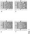
- FIG. 1illustrates an example acoustophoresis process using a transducer and reflector to create an acoustic standing wave for trapping particles and separating them from a fluid by enhanced gravitational settling.
- FIG. 2illustrates an example cell concentration and washing process (“diafiltration”) according to the present disclosure using acoustophoresis.
- FIG. 3illustrates another example cell concentration and washing process (push through) according to the present disclosure using acoustophoresis.
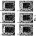
- FIG. 4shows six photographs that, from left to right and top to bottom, show the progression of cells being trapped in an acoustophoretic device before a second media mixture (dyed blue) is flowed into the device and gradually replaces the first media (dyed red).
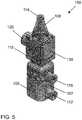
- FIG. 5is a perspective view of an example acoustophoretic device according to the present disclosure.
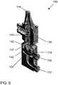
- FIG. 6is a cross-sectional illustration of the acoustophoretic device of FIG. 5 .
- FIG. 7is a graph showing the performance of the acoustophoretic device of FIG. 5 .
- the x-axisis elapsed time (minutes) and runs from 0 to 40 in increments of 5.
- the left-side y-axisis permeate density reduction (%) and runs from 0 to 100 in increments of 10.
- the right-side y-axisis permeate cell density ( ⁇ 10 6 cells/mL) and runs from 0.00 to 2.00 in increments of 0.20.
- the uppermost solid linerepresents permeate reduction density (%).
- the lowermost solid linerepresents permeate cell density.
- the middle line running substantially horizontally across the pagerepresents feed cell density for reference purposes.
- FIG. 8is a conventional single-piece monolithic piezoelectric material used in an ultrasonic transducer.
- FIG. 9is an example rectangular piezoelectric array having 16 piezoelectric elements used in the transducers of the present disclosure.
- FIG. 10is another example rectangular piezoelectric array having 25 piezoelectric elements used in the transducers of the present disclosure.
- FIG. 11is a diagram illustrating a piezoelectric material having 16 piezoelectric elements operated in out-of-phase modes. Dark elements indicate a 0° phase angle and light elements indicate a 180° phase angle.
- FIG. 12illustrates a kerfed piezoelectric material (top) versus a transducer array that has piezoelectric elements joined together by a potting material (bottom).
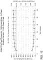
- FIG. 13is a graph showing the performance of an acoustophoretic device according to the present disclosure having a 16-element piezoelectric array, with the elements operated in-phase with one another.
- the x-axisis elapsed time (minutes) and runs from 0 to 60 in increments of 10.
- the left-side y-axisis permeate density reduction (%) and runs from 0 to 100 in increments of 10.
- the right-side y-axisis permeate cell density ( ⁇ 10 6 cells/mL) and runs from 0.00 to 2.50 in increments of 0.50.
- the uppermost solid linerepresents permeate reduction density (%).
- the lowermost solid linerepresents permeate cell density.
- the middle line running substantially horizontally across the pagerepresents feed cell density for reference purposes.
- FIG. 14is a graph showing the T-cell concentration performance of an acoustophoretic process according to the present disclosure with a low cell density culture.
- the x-axisis elapsed time (minutes) and runs from 0 to 25 in increments of 5.
- the left-side y-axisis percent reduction (%) and runs from 0 to 100 in increments of 10.
- the right-side y-axisis cell density ( ⁇ 10 6 cells/mL) and runs from 0.00 to 1.60 in increments of 0.20.
- the upper solid linerepresents permeate reduction (%).
- the lower solid linerepresents permeate cell density.
- the dashed linerepresents feed cell density for reference purposes.
- FIG. 15is a graph showing the percent density reduction (PDR) dependency on concentration and flow rate for an acoustophoretic process according to the present disclosure.
- the x-axisis time (minutes) and runs from 0 to 40 in increments of 5.
- the y-axisis permeate density reduction (%) and runs from 0 to 100 in increments of 10.
- the line having circle-shaped data pointsrepresents a mixture having an initial cell concentration of 5 ⁇ 10 6 cells/mL.
- the line having x-shaped data pointsrepresents a mixture having an initial cell concentration of 3 ⁇ 10 6 cells/mL.
- the line having triangle-shaped data pointsrepresents a mixture having an initial cell concentration of 1 ⁇ 10 6 cells/mL at a flow rate of 20 mL/minute.
- the line having diamond-shaped data pointsrepresents a mixture having an initial cell concentration of 1 ⁇ 10 6 cells/mL at a flow rate of 10 mL/minute.
- FIG. 16is a graph showing the T-cell performance for an acoustophoretic process according to the present disclosure with a high cell density culture.
- the x-axisis elapsed time (minutes) and runs from 0 to 25 in increments of 5.
- the left-side y-axisis percent reduction (%) and runs from 0 to 100 in increments of 10.
- the right-side y-axisis cell density ( ⁇ 10 6 cells/mL) and runs from 0.00 to 3.00 in increments of 0.50.
- the upper solid linerepresents permeate density reduction (%).
- the lower solid linerepresents permeate cell density.
- the dashed linerepresents feed cell density for reference purposes.
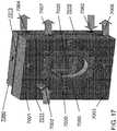
- FIG. 17is a perspective view of an example acoustophoretic device according to the present disclosure including a cooling unit for cooling the transducer.
- FIG. 18is a graph showing the temperature profile of an acoustophoretic device without active cooling.
- the x-axisis elapsed time (minutes) and runs from 0.00 to 20.00 in increments of 2.00.
- the y-axisis temperature (° C.) and runs from 17.00 to 33.00 in increments of 2.00.
- the lowermost line along the right side of the graphrepresents the feed temperature (° C.).
- the uppermost line along the right side of the graphrepresents the core temperature (° C.).
- the middle line along the right side of the graphrepresents the permeate temperature (° C.).
- FIG. 19is a graph showing the temperature profile of an acoustophoretic device with active cooling of the transducer.
- the x-axisis elapsed time (minutes) and runs from 0.00 to 20.00 in increments of 2.00.
- the y-axisis temperature (° C.) and runs from 17.00 to 33.00 in increments of 2.00.
- the lowermost line along the right side of the graphrepresents the feed temperature (° C.).
- the uppermost line along the right side of the graphrepresents the core temperature (° C.).
- the middle line along the right side of the graphrepresents the permeate temperature (° C.).
- FIG. 20illustrates a process for concentrating, washing, and/or separating microcarriers and cells according to the present disclosure.
- the leftmost portionrepresents a first step of receiving microcarriers and cells surrounded by a bioreactor serum from a bioreactor and concentrating the microcarriers with attached cells in an acoustophoretic device according to the present disclosure.
- the middle portionrepresents a second step of washing the concentrated microcarriers with attached cells to remove the bioreactor serum.
- the rightmost portionrepresents a third step of trypsinizing the microcarriers and separating the microcarriers from the cells in a fourth step.
- the bottom portionrepresents a final wash and concentrate step that can be employed as needed.
- FIG. 21shows media exchange in an acoustophoretic device according to the present disclosure.
- the “Concentrate” photographshows the concentrate (e.g., concentrated microcarriers with attached T cells) surrounded by a first media (dyed red).
- the “Wash Pass 1” photographshows the microcarriers with attached T cells after a first wash pass using a second media (dyed blue).
- the “Wash Pass 2” photographshows the microcarriers with attached T cells after a second wash pass.
- the rightmost “Wash Pass 3” photographshows the microcarriers with attached T cells after a third wash pass, and is almost completely blue.
- FIG. 22shows microscopic images of the media exchange shown in FIG. 21 .
- FIG. 22shows a microscopic image of the microcarriers with T attached cells in the feed and during the three wash passes, and the concentration of separated microcarriers and T cells in the permeate.
- FIG. 23shows the concentration of T cells in the acoustophoretic device before acoustophoresis (top row of photographs) and after one acoustophoresis pass (bottom row of photographs).
- FIG. 24shows the concentration of microcarriers with attached T cells in the feed into the acoustophoretic device (top row of photographs) and the concentration of separated microcarriers and T cells in the permeate drawn out of the acoustophoretic device (bottom row of photographs).
- the dark circular itemsindicate microcarriers, and the lighter area indicates T cells.
- FIG. 25shows microscopic images of the concentration of microcarriers with attached T cells in the feed and the concentration of separated microcarriers and T cells in the permeate.
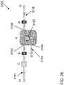
- FIG. 26is a schematic of an example acoustophoretic system according to the present disclosure.
- FIG. 27is a schematic of another example acoustophoretic system according to the present disclosure including waste and concentrate transfer bags.
- FIG. 28is a schematic of an example acoustophoretic system according to the present disclosure showing the flow path of the feed material through the system.
- FIG. 29is a schematic of the example acoustophoretic system of FIG. 28 showing the flow path of the wash material through the system.
- FIG. 30is a schematic of the example acoustophoretic system of FIG. 28 showing draining of the system.
- FIG. 31illustrates a culture bag for use in the acoustophoretic systems according to the present disclosure.
- FIG. 32illustrates the concentrate transfer bag of FIG. 31 disposed within a tank filled with fluid and a conveyor system for moving the transducer relative to the bag.
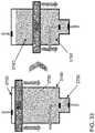
- FIG. 33illustrates moving the transducer from an upper portion of the bag to a lower portion of the bag to concentrate cellular material in the lower portion of the bag.
- FIG. 34illustrates concentrating the cellular material in the lower portion of the bag and sealing the bag between the upper and lower portions.
- FIG. 35illustrates removing the waste from the lower portion of the bag via the waste outlet, introducing a new wash buffer via the drain port, and then separating the lower portion of the bag containing the concentrated cellular material from the upper portion of the bag.
- the term “comprising”may include the embodiments “consisting of” and “consisting essentially of.”
- the terms “comprise(s),” “include(s),” “having,” “has,” “can,” “contain(s),” and variants thereof, as used herein,are intended to be open-ended transitional phrases, terms, or words that require the presence of the named components/steps and permit the presence of other components/steps.
- compositions or processesas “consisting of” and “consisting essentially of” the enumerated components/steps, which allows the presence of only the named components/steps, along with any impurities that might result therefrom, and excludes other components/steps.
- a value modified by a term or terms, such as “about” and “substantially,”may not be limited to the precise value specified.
- the approximating languagemay correspond to the precision of an instrument for measuring the value.
- the modifier “about”should also be considered as disclosing the range defined by the absolute values of the two endpoints. For example, the expression “from about 2 to about 4” also discloses the range “from 2 to 4.”
- the terms “upper” and “lower”are relative to each other in location, e.g. an upper component is located at a higher elevation than a lower component in a given orientation, but these terms can change if the device is flipped.
- the terms “inlet” and “outlet”are relative to a fluid flowing through them with respect to a given structure, e.g. a fluid flows through the inlet into the structure and flows through the outlet out of the structure.
- upstream and “downstream”are relative to the direction in which a fluid flows through various components, e.g. the flow fluids through an upstream component prior to flowing through the downstream component. It should be noted that in a loop, a first component can be described as being both upstream of and downstream of a second component.
- horizontal and verticalare used to indicate direction relative to an absolute reference, e.g. ground level.
- upwards and downwardsare also relative to an absolute reference; an upwards flow is always against the gravity of the earth.
- Two numbersare of the same order of magnitude if the quotient of the larger number divided by the smaller number is a value of at least 1 and less than 10.
- the acoustophoretic technology of the present disclosureemploys acoustic standing waves to concentrate, wash, and/or separate materials (such as particles or a secondary fluid) in a primary or host fluid.
- acoustic standing wavesto concentrate, wash, and/or separate materials (such as particles or a secondary fluid) in a primary or host fluid.
- an ultrasonic transducer Tcreates an acoustic wave in the fluid, which interacts with a reflector R positioned across from the ultrasonic transducer to create an acoustic standing wave.
- a reflector Ris illustrated in FIG. 1
- another transducermay be used to reflect and/or generate acoustic energy to form the acoustic standing wave.
- the acoustic standing wave(s)traps (retains or holds) the material (e.g., secondary phase materials, including fluids and/or particles).
- the scattering of the acoustic field off the materialresults in a three-dimensional acoustic radiation force, which acts as a three-dimensional trapping field.
- the three-dimensional acoustic radiation force generated in conjunction with an ultrasonic standing waveis referred to in the present disclosure as a three-dimensional or multi-dimensional standing wave.
- the acoustic radiation forceis proportional to the particle volume (e.g. the cube of the radius) of the material when the particle is small relative to the wavelength.
- the acoustic radiation forceis proportional to frequency and the acoustic contrast factor.
- the acoustic radiation forcescales with acoustic energy (e.g. the square of the acoustic pressure amplitude). For harmonic excitation, the sinusoidal spatial variation of the force drives the particles to the stable positions within the standing waves.
- the particleWhen the acoustic radiation force exerted on the particles is stronger than the combined effect of fluid drag force and buoyancy and gravitational force, the particle can be trapped within the acoustic standing wave field, as shown in the upper right image (B) of FIG. 1 .
- this trappingresults in coalescing, clumping, aggregating, agglomerating, and/or clustering of the trapped particles. Additionally, secondary inter-particle forces, such as Bjerkness forces, aid in particle agglomeration.
- the particlescan grow to a certain size at which gravitational forces on the particle cluster overcome the acoustic radiation force. At such size, the particle cluster can fall out of the acoustic standing wave, as shown in the lower right image (D) of FIG. 1 .
- the ultrasonic transducer(s)generate a three-dimensional or multi-dimensional acoustic standing wave in the fluid that exerts a lateral force on the suspended particles to accompany the axial force so as to increase the particle trapping capabilities of the standing wave.
- a planar or one-dimensional acoustic standing wavemay provide acoustic forces in the axial or wave propagation direction.
- the lateral force in planar or one-dimensional acoustic wave generationmay be two orders of magnitude smaller than the axial force.
- the multi-dimensional acoustic standing wavemay provide a lateral force that is significantly greater than that of the planar acoustic standing wave.
- the lateral forcemay be of the same order of magnitude as the axial force in the multi-dimensional acoustic standing wave.
- the acoustic standing waves of the present disclosurecan be used to trap particles (e.g. therapeutic cells such as T cells, B cells, NK cells) suspended in a first media in the standing wave.
- the first mediacan then be replaced with a second media (e.g., a biocompatible wash or buffer solution).
- a second mediae.g., a biocompatible wash or buffer solution.
- the host fluid of the particlescan be replaced.
- acoustophoresisPrior to replacing the first media with the second media, acoustophoresis can be used to perform a diafiltration process, as shown in FIG. 2 .
- acoustophoresiscan be used to reduce the volume of the initial mixture, for example by at least 10 ⁇ , including 20 ⁇ and up to 100 ⁇ or more.
- the cell concentrationmay be increased by at least 10 ⁇ , including 20 ⁇ and up to 100 ⁇ or more.
- This initial reduction processis the first volume reduction step (A).
- the second mediae.g., a biocompatible wash or buffer solution
- the new mixture of the cells and second mediacan be subjected to an acoustophoretic volume reduction step (C). This series of operations is referred to as a “diafiltration” process.
- FIG. 3illustrates a single-step, push-through process in which particles/cells are trapped in the acoustic standing wave and held in the acoustophoretic device.
- the second mediae.g., a biocompatible wash or buffer solution
- the push-through processmore than 90%, including up to 99% or more, of the first media can be removed from the particles/cells.
- the push-through processcan be employed as a continuous, single-use process that uses less buffer solution and less time than the diafiltration process of FIG. 2 .
- FIG. 4shows six photographs that, from left to right and top to bottom, show the progression of cells being trapped in an acoustophoretic device before a second media mixture (dyed blue) is flowed into the device and gradually replaces the first media (dyed red).
- a 150 mL feed volumewas used with 80 mL of electroporation media wash for the second media.
- the concentratewas drawn off at a flow rate of 10 mL/minute. As can be seen in these pictures, over time the first media is replaced with the second media.
- the acoustophoretic device 100includes a flow chamber 110 having at least one inlet and at least one outlet.
- the flow chamber 110includes inlet 112 , permeate outlet 114 , concentrate outlet 116 , an ultrasonic transducer 120 , and a reflector 130 .
- the inlet 112can, in certain embodiments, serve the dual function of introducing the cells surrounded by the first media into the flow chamber 110 in addition to introducing the second media into the flow chamber 110 .
- separate inletscan be used for introducing the first and second media.
- the flow chamber 110is the region of the device 100 through which is flowed the cells surrounded by the first media.
- the flow chamber 110is defined by inlet 112 , permeate outlet 114 , and concentrate outlet 116 .
- the flow chamber 110is further defined by a sidewall 115 to which the ultrasonic transducer 120 and the reflector 130 are coupled. As seen here, the sidewall is shaped so that the ultrasonic transducer and reflector are located on opposite sides thereof.
- Inlet 112is located at a first end 106 of the flow chamber 110 .
- the ingress of material through the inlet 112can be configured to occur toward the bottom end of the inlet 112 , such that the inflow of fluid into the flow chamber 110 occurs closer to the bottom end of the flow chamber 110 than the top end thereof.
- the inlet 112is located along a first side 107 of the device 100 .
- the first side 107 of the devicealso houses the reflector 130 , while a second side 109 of the device, opposite the first side thereof, houses the ultrasonic transducer 120 .
- the inlet 112could alternatively be located along the second side 109 of the device (e.g., on the same side as the ultrasonic transducer) or on another side of the device.
- the permeate outlet 114is located at a second end 108 of the flow chamber 100 .
- the permeate outlet 114is generally used to recover the first media and residual cells from the flow chamber 110 .
- the concentrate outlet 116is located between the inlet 112 and the permeate outlet 114 , below the ultrasonic transducer 120 and the reflector 130 .
- the concentrate outlet 116is generally configured to recover the cells from the flow chamber 110 . In certain embodiments, however, it may be desired to recover other material (e.g., microcarriers) from the device, in which case the microcarriers can be recovered by the concentrate outlet and the cells can be recovered via the permeate outlet along with the media).
- the permeate outlet 114is generally located above the ultrasonic transducer 120 and the reflector 130
- the concentrate outlet 116is generally located below the ultrasonic transducer 120 and the reflector 130 .
- the device 100is vertically oriented, such that the first end 106 of the device is the bottom end thereof and the second end 108 of the device is the top end thereof. In this way, the cells surrounded by the first media is introduced at the bottom end of the device 100 and flows vertically upwards through the flow chamber from the inlet 112 toward the permeate outlet 114 .
- the device 100also includes a collector 140 .
- the collector 140is located in the flow chamber 110 between the inlet 112 and the ultrasonic transducer 120 and the reflector 130 .
- the collector 140is located above the concentrate outlet 116 and, in particular, is defined by angled walls 142 that lead to the concentrate outlet 116 .
- the collector 140leads into a common well defined by angled walls 142 that taper downwards in cross-sectional area (i.e. larger area to smaller area) to a vertex at the bottom of the collector, which is fluidically connected to and drains off one side into the concentrate outlet 116 via flowpath 119 .
- the multi-dimensional acoustic standing wavecan direct the concentrated cells to the collector 140 for collection and removal from the flow chamber 110 via the concentrate outlet 116 .
- An annular plenum 117surrounds the collector 140 , permitting the mixture of host fluid/cells to flow from the inlet 112 around the collector 140 into the flow chamber 110 .
- the collectorleads to a collection container that is filled with the second media.
- the second mediais not flowed through the flow chamber of the device. Instead, as the cells are trapped in the acoustic standing wave and form clusters that grow to a critical size and subsequently fall out of the multi-dimensional acoustic standing wave, the cell clusters fall into the collector and are led to the collection container.
- the collection containercan be separable from the rest of the device.
- fluidflows through the device upwards.
- the cells surrounded by the first mediaenters the device through inlet 112 at a bottom end of the device and then makes a sharp turn to flow upwards. This change in direction desirably reduces turbulence, producing near plug flow upwards through the device.
- Flowcontinues upwards through the annular plenum 117 and up into the flow chamber 110 .
- the cellsencounter the multi-dimensional acoustic standing wave(s), which traps the cells, as explained herein. Concentration of the cells occurs within the acoustic standing wave(s), which can also cause coalescence, clumping, aggregation, agglomeration and/or clustering of the cells.
- the cellsAs the cells are concentrated, they eventually overcome the combined effect of the fluid flow drag forces and acoustic radiation force, and they fall downwards into collector 140 . They can then be flowed through flowpath 119 and collected at concentrate outlet 116 . A much higher number of cells is obtained in a smaller volume (i.e., the target cells are concentrated).
- FIG. 7is a graph showing the performance of the acoustophoretic device of FIG. 5 .
- the devicewas operated at a fixed frequency of 2.234 MHz for a mixture having a feed cell density of about 1.5 ⁇ 10 6 cells/mL.
- the deviceachieved a permeate density reduction (PDR) of greater than 95% over about 35 minutes and a permeate cell density of less than 0.10 ⁇ 10 6 cells/mL over the same time period.
- PDRpermeate density reduction
- the piezoelectric transducer(s) of the acoustophoretic devices and systems of the present disclosurecan be single monolithic piezoelectric materials or can be made from an array of piezoelectric materials.
- the piezoelectric materialcan be a ceramic material, a crystal or a polycrystal, such as PZT-8 (lead zirconate titanate).
- FIG. 8shows a monolithic, one-piece, single electrode piezoelectric crystal 200 .
- the piezoelectric crystalhas a substantially square shape, with a length 203 and a width 205 that are substantially equal to each other (e.g. about one inch).
- the crystal 200has an inner surface 202 , and the crystal also has an outer surface 204 on an opposite side of the crystal which is usually exposed to fluid flowing through the acoustophoretic device.
- the outer surface and the inner surfaceare relatively large in area, and the crystal is relatively thin (e.g. about 0.040 inches for a 2 MHz crystal).
- FIG. 9shows a piezoelectric crystal 200 ′ made from an array of piezoelectric materials.
- the inner surface 202 of this piezoelectric crystal 200 ′is divided into a piezoelectric array 206 with a plurality of (i.e. at least two) piezoelectric elements 208 .
- the arrayis still a single crystal.
- the piezoelectric elements 208are separated from each other by one or more channels or kerfs 210 in the inner surface 202 .
- the width of the channeli.e. between piezoelectric elements
- the depth of the channelcan be from about 0.001 inches to about 0.02 inches.
- a potting material 212e.g., epoxy, Sil-Gel, and the like
- the potting material 212is non-conducting, acts as an insulator between adjacent piezoelectric elements 208 , and also acts to hold the separate piezoelectric elements 208 together.
- the array 206contains sixteen piezoelectric elements 208 (although any number of piezoelectric elements is possible), arranged in a rectangular 4 ⁇ 4 configuration (square is a subset of rectangular). Each of the piezoelectric elements 208 has substantially the same dimensions as each other.
- the overall array 200 ′has the same length 203 and width 205 as the single crystal illustrated in FIG. 8 .
- FIG. 10shows another embodiment of a transducer 200 ′′.
- the transducer 200 ′′is substantially similar to the transducer 200 ′ of FIG. 9 , except that the array 206 is formed from twenty-five piezoelectric elements 208 in a 5x5 configuration. Again, the overall array 200 ′′ has the same length 203 and width 205 as the single crystal illustrated in FIG. 8 .
- Each piezoelectric element in the piezoelectric array of the present disclosuremay have individual electrical attachments (e.g. electrodes), so that each piezoelectric element can be individually controlled for frequency and power. These elements can share a common ground electrode.
- This configurationallows for not only the generation of a multi-dimensional acoustic standing wave, but also improved control of the acoustic standing wave. In this way, it is possible to drive individual piezoelectric elements (or multiple, separate ultrasonic transducers) with arbitrary phasing and/or different or variable frequencies and/or in various out-of-phase modes.
- FIG. 11illustrates an exemplary 0-180-0-180 mode, though additional modes can be employed as desired, such as a 0-180-180-0 mode.
- additional modescan be employed as desired, such as a 0-180-0-180-0 mode, a 0-0-180-0-0 mode, a 0-180-180-180-0 mode, or a 0-90-180-90-0 mode.
- the arraycould also be driven, for example, such that a checkerboard pattern of phases is employed, such as is shown in FIG. 11 .
- a single ultrasonic transducer that has been divided into an ordered arraycan be operated such that some components of the array are out of phase with other components of the array.
- the piezoelectric arraycan be formed from a monolithic piezoelectric crystal by making cuts across one surface so as to divide the surface of the piezoelectric crystal into separate elements.
- the cutting of the surfacemay be performed through the use of a saw, an end mill, or other means to remove material from the surface and leave discrete elements of the piezoelectric crystal between the channels/grooves that are thus formed.
- a potting materialmay be incorporated into the channels/grooves between the elements to form a composite material.
- the potting materialcan be a polymer, such as epoxy.
- the piezoelectric elements 208are individually physically isolated from each other. This structure can be obtained by filling the channels 210 with the potting material, then cutting, sanding or grinding the outer surface 204 down to the channels. As a result, the piezoelectric elements are joined to each other through the potting material, and each element is an individual component of the array. Put another way, each piezoelectric element is physically separated from surrounding piezoelectric elements by the potting material.
- FIG. 12is a cross-sectional view comparing these two embodiments.
- FIG. 9On top, a crystal as illustrated in FIG. 9 is shown. The crystal is kerfed into four separate piezoelectric elements 208 on the inner surface 202 , but the four elements share a common outer surface 204 . On the bottom, the four piezoelectric elements 208 are physically isolated from each other by potting material 212 . No common surface is shared between the four elements.
- FIG. 13is a graph showing the performance of an acoustophoretic device according to the present disclosure having a 16-element piezoelectric array.
- the piezoelectric arraywas operated at a fixed frequency of 2.244 MHz for a mixture having a feed cell density of about 2.00 ⁇ 10 6 cells/mL.
- the deviceachieved a permeate density reduction (PDR) of about 95% over about 60 minutes and a permeate cell density of about 0.10 ⁇ 10 6 cells/mL over the same time period.
- PDRpermeate density reduction
- the concentration efficiency of the acoustophoretic devicewas tested. First, a T-cell suspension having a cell density of 1 ⁇ 10 6 cells/mL was used. A feed volume of between about 500 and 1000 mL was used at a flow rate of 10-15 mL/minute. The results are graphically depicted in FIG. 14 . The device exhibited a concentration factor of between 10 ⁇ and 20 ⁇ , a 90% cell recovery, and a 77% washout efficiency (i.e., the amount of the first media that was displaced by the second media) over ten minutes of testing. A 10° C. temperature increase was observed.
- a yeast mixturewas then used to test the dependency of the percent density reduction (PDR) on concentration and flow rate. The results are graphically depicted in FIG. 15 . As seen here, the higher initial cell concentrations generally resulted in a greater PDR. Additionally, the varied flow rate (from 20 mL/min to 10 mL/min) did not have an observed effect on the PDR.
- the concentration efficiency of the acoustophoretic devicewas again tested with a higher cell density.
- a T-cell suspension having a cell density of 5 ⁇ 106 cells/mLwas used.
- a feed volume of 1000 mLwas used at a flow rate of 10-15 mL/minute.
- the resultsare graphically depicted in FIG. 16 .
- the deviceexhibited a concentration factor of better than 10 ⁇ , a 90% cell recovery, and a 77% washout efficiency over one hour of testing. A 10° C. temperature increase was again observed.
- a cooling unitwas developed for actively cooling the transducer, such as cooling unit 7060 coupled to the rear wall 7013 of acoustophoretic device 7000 depicted in FIG. 17 .
- the cooling unit 7060includes an independent flow path that is separate from the flow path through the device containing the fluid that is to be exposed to the multi-dimensional acoustic standing wave.
- a coolant inlet 7062is adapted to permit the ingress of a cooling fluid into the cooling unit.
- a coolant outlet 7064serves as the outlet through which the coolant and waste heat exit the cooling unit.
- the coolant inletis located below the coolant outlet, though this path can be varied as desired.
- the coolant that flows through the cooling unitcan be any appropriate fluid.
- the coolantcan be water, air, alcohol, ethanol, ammonia, or some combination thereof.
- the coolantcan, in certain embodiments, be a liquid, gas, or gel.
- the coolantcan be an electrically non-conductive fluid to prevent electric short-circuits.
- the cooling unitcan be used to cool the ultrasonic transducer, which can be particularly advantageously when the device is to be run continuously with repeated processing and recirculation for an extended period of time (e.g., perfusion).
- the cooling unitcan also be used to cool the host fluid running through the device 7000 , if desired.
- FIG. 18graphically shows the temperature profile of the acoustophoretic device without any active cooling (e.g., without a cooling unit for the transducer).
- the temperature difference between the feed and the coree.g., the transducer
- the temperature difference between the feed and the corewas 8.6° C.
- FIG. 19graphically shows the temperature profile of the acoustophoretic device with active cooling (e.g., with a cooling unit for the transducer). As seen in FIG. 19 , through the use of active cooling the temperature difference between the feed and the core was reduced to 6.1° C.
- FIG. 20illustrates a four-step process (with an optional fifth step) for concentrating, washing, and separating microcarriers from cells.
- the first step in the processinvolves concentrating the microcarriers with attached cells in an acoustophoretic device, such as those described herein.
- the microcarriers and attached cellscan be introduced to the acoustophoretic device by receiving the microcarriers with attached cells from a bioreactor.
- the microcarriers and cellsare suspended in a first media (e.g., growth serum or preservative material used to keep the cells viable in the bioreactor).
- the microcarriers with attached cells surrounded by the first mediaare concentrated by the acoustic standing wave(s) generated in the acoustophoretic device.
- the concentrated microcarriers with attached cellsare then washed with a second media to remove the first media (e.g., bioreactor growth serum or preservative material).
- the third stepis to then introduce a third media containing an enzyme into the acoustophoretic device to detach the cells from the microcarriers through enzymatic action of the second media.
- trypsinis the enzyme used to enzymatically detach the cells from the microcarriers.
- the multi-dimensional acoustic standing wavecan then be used to separate the cells from the microcarriers. Usually, this is done by trapping the microcarriers in the multi-dimensional acoustic standing wave, while the detached cells pass through with the third media. However, the cells can be trapped instead, if desired.
- the separated cellsmay optionally be concentrated and washed again, as desired.
- the microcarriersAfter being concentrated and trapped/held in the multi-dimensional acoustic standing wave, the microcarriers can coalesce, clump, aggregate, agglomerate, and/or cluster to a critical size at which point the microcarriers fall out of the acoustic standing wave due to enhanced gravitational settling.
- the microcarrierscan fall into a collector of the acoustophoretic device located below the acoustic standing wave, to be removed from the flow chamber.
- steps one and twowere performed using red and blue food dye to make colored fluid.
- the concentration mixtureincluded SoloHill microcarriers in red fluid.
- the wash mixtureincluded blue fluid and was passed through the device three times.
- the concentratewas observed under a microscope, as shown in the leftmost image of FIG. 21 .
- the concentration stepwas shown to have a 99% efficiency.
- the remaining three images in FIG. 21show microscopic images after the first, second, and third wash passes, respectively. As seen from left to right in FIG. 21 , the first media (dyed red) is progressively washed out by a second media (dyed blue) over a series of wash passes.
- the light absorbance datais shown in the table below.
- FIG. 22shows microscopic images of the microcarriers and attached cells during the concentration and washing steps.
- the leftmost image in the top rowshows the microcarriers and attached cells in the feed, prior to introduction into the acoustophoretic device.
- the rightmost image in the top rowshows the microcarriers and attached cells in the permeate, after concentration in the acoustophoretic device.
- the bottom row of imagesshow the microcarriers and attached cells in the device during the washing step, namely during the first, second, and third wash passes, from left to right.
- FIG. 23shows the concentration of T-cells after being separated in the acoustophoretic device.
- the top row of imagesshow the T-cells before acoustophoresis with a concentration of 1.14 ⁇ 0.03 ⁇ 10 6 cells/mL.
- the bottom row of imagesshow the T-cells after acoustophoresis with a concentration of 1.13 ⁇ 0.02 ⁇ 10 6 cells/mL.
- the comparable concentrationsevidence that substantially all of the cells pass through the acoustophoretic device, as the concentration was substantially unchanged by acoustophoresis.
- FIG. 24shows the presence of SoloHill microcarriers and T-Cells in the acoustophoretic device under 4 ⁇ magnification.
- the top row of imagesshow the microcarriers and cells in the feed before acoustophoresis.
- the bottom row of imagesshow the microcarriers and cells in the permeate after the cells have been separated out by acoustophoresis.
- the difference in the number of microcarriers with the application of acoustophoresisevidences the feasibility of using the device for trapping the microcarriers in the device and separating the cells therefrom.
- the feasibility of this technique and the resultsare further evidenced by the images in FIG. 25 , which show microscopic images of the microcarriers and cells in the feed (top row of images) and permeate (bottom row of images) after concentration and the first, second, and third washes, from left to right.
- the testing of the acoustophoretic concentrating, washing, and separating processshowed that the process is appropriate for cell therapy and microcarrier applications.
- the concentrate and wash stepswere performed with a resulting efficiency of greater than 99%, and the separating step e.g., separating the cells from the microcarriers, was performed with greater than 98% efficiency.
- FIG. 26depicts an example embodiment of an acoustophoretic system/process 3100 employing an acoustophoretic device A, such as the acoustophoretic devices previously described.
- the device Aincludes a feed port 3102 , a drain port 3104 , a wash outlet 3108 , and an ultrasonic transducer 3120 configured to create a multi-dimensional acoustic standing wave in the device, as explained in great detail herein.
- the feed port 3102 of this example embodimentis generally configured to operate as an inlet to introduce a fluid into the device, with the fluid typically including material entrained therein, such as cells and/or microcarriers.
- the feed port 3102is connected to feed line 3112 .
- feed line 3112begins with a swabable barb valve D (Halkey Roberts) upstream of the feed port 3102 .
- a swabable barb valve DHalkey Roberts
- Also included in the feed line 3112 upstream of the feed port 3102 in this example embodimentare a disposable pump head C (NaoPump) and a temperature sensor B (SciLog SciTemp).
- the pump Ccan be used, for example, to regulate the flow rate of the acoustophoretic device so that gravity/buoyancy can act on cell clusters.
- the feed line 3112generally terminates at the feed port 3102 of the device A.
- the drain port 3104 of this example embodimentis generally configured to operate as a concentrate outlet for drawing off concentrate from the device A. As can be seen here, the drain port 3104 is connected to concentrate line 3114 . In this example embodiment, concentrate line 3114 begins at the drain port 3104 of the device A and terminates with a swabable barb valve D (Halkey Roberts) downstream of the drain port 3104 .
- Dswabable barb valve
- the wash outlet 3108 of this example embodimentis generally configured to remove material from the device A, such as separated cells and washed-out fluid and media. As can be seen here, the wash outlet 3108 is connected to wash line 3118 . In this example embodiment, wash line 3118 begins at the wash outlet 3108 of the device A. Also included in the waste line 3118 downstream of the waste outlet 3108 in this example embodiment is a temperature sensor B (SciLog SciTemp) and a swabable barb valve D (Halkey Roberts).
- the feed line 3112 , concentrate line 3114 , and waste line 3118 of this example embodimentare customarily made of tubing, preferably biopharmaceutical grade tubing (e.g., AdvantaHex Biopharmaceutical Grade TPE tubing having a 3.18 mm inner diameter and 6.35 mm outer diameter).
- biopharmaceutical grade tubinge.g., AdvantaHex Biopharmaceutical Grade TPE tubing having a 3.18 mm inner diameter and 6.35 mm outer diameter.
- FIG. 27another example embodiment of an acoustophoretic system/process 3200 is depicted.
- the acoustophoretic device 3200 of FIG. 27is very similar to the acoustophoretic system/process 3100 of FIG. 26 .
- the acoustophoretic system/process 3200 depicted in FIG. 32includes a drain port 3104 configured to operate as both a wash inlet and a concentrate outlet.
- the drain port 3104is used to introduce a wash media/buffer into the device A and to draw off concentrate from the device A. Because of the dual purpose of the drain port 3104 , as can be seen here, the drain port 3104 is connected to both a concentrate line 3114 and a wash line 3116 .
- wash line 3116 of this example embodimentbegins at swabable barb valve D (Halkey Roberts), runs through the stopcock F (Halkey Roberts), and terminates at the drain port 3104 .
- the concentrate line 3114begins at the drain port 3104 , runs through the stopcock F, and terminates at a collection container E (Charter Medical transfer bag, 400 mL). In this way, the concentrate line 3114 and the wash line 3116 share the valve/stopcock F, where the two lines are joined and share a common tubing between the stopcock F and the drain port 3104 .
- this acoustophoretic system/process 3200differs from the acoustophoretic system/process 3100 depicted in FIG. 31 by the replacement of the barb valve at the end of the waste line 1318 in system 3100 with a collection container E (Charter Medical transfer bag, 400 mL) in system 3200 .
- the feed line 3112 , concentrate line 3114 , wash line 3116 , and waste line 3118are customarily made of tubing, preferably biopharmaceutical grade tubing (e.g., Escelero RNT Clean Flexible PVC tubing tubing having a 3.18 mm inner diameter and 4.76 mm outer diameter).
- collection containers E at the ends of the concentrate and waste linesadvantageously creates an enclosed primary environment within which concentration, washing, and/or separation of cells and cellular materials can occur, which helps to prevent the cells/cell culture/cellular material from being exposed to possible intrusions, pathogens, or outside cellular influences that would be harmful.
- FIGS. 28-30illustrate another example embodiment of an acoustophoretic system/process 2800 including a disposable acoustophoretic device 2810 with solenoid pinch valves that control the flow of fluid therethrough.
- the systemincludes a feed tank 2820 , a wash tank 2830 , and an air intake 2805 .
- the air intake 2805runs through an air intake valve 2804 .
- Feed line 2821runs from the feed tank 2820 .
- the air intake and the feed line 2821are joined together by a Y-connector into common feed line 2811 , which runs into feed selector valve 2801 .
- a wash line 2831runs from the wash tank 2830 , and also runs into feed selector valve 2801 .
- Feed selector valve 2801permits only one line to be open at a given time (valves 2802 , 2803 also operate in this manner). Wash line 2831 and feed line 2811 are joined together by a Y-connector downstream of the feed selector valve 2801 into input line 2812 .
- Input line 2812passes through pump 2806 to inflow selector valve 2802 , which is downstream of the feed selector valve 2801 and upstream of the acoustophoretic device 2810 .
- the inflow selector valve 2802selectively controls the inflow of feed or wash into the acoustophoretic device 2810 through either feed port 2602 or wash/drain port 2604 .
- a feed line 2813runs from the inflow selector valve 2802 to feed port 2602 .
- a wash line 2814runs from the inflow selector valve 2802 to common line 2815 and into wash/drain port 2604 .
- an outflow selector valve 2803is located downstream of the acoustophoretic device 2810 and controls the outflow of fluid therefrom.
- a waste line 2816runs from waste port 2608 through outflow selector valve 2803 and subsequently to waste tank 2850 .
- the common line 2815runs into drain line 2817 , which then passes through outflow selector valve 2803 and subsequently to concentrate tank 2840 .
- These tanks 2840 , 2850can be, for example, bags such as the culture bag that will be described further herein in FIG. 31 .
- the outflow selector 2803thereby selectively controls the flow of fluid to the concentrate tank and waste tank.
- FIG. 28also illustrates the flow path of the feed material through the system.
- feed selector valve 2801is operated with the bottom open (and top closed), so that the feed from feed tank 2820 flows through.
- Inflow selector valve 2802is operated with the top open (and bottom closed), so that the feed material enters the acoustophoretic device 2810 via feed port 2602 .
- the outflow selector valve 2803is also operated with the top open (and bottom closed) so that the fluid/first media of the feed material flows through to waste tank 2850 .
- the targeted particles in the feed materiale.g., microcarriers or cells
- FIG. 29illustrates the flow path of the wash material through the system.
- Feed selector valve 2801is operated with the top open (and bottom closed), so that the wash material from wash tank 2830 flows through.
- the inflow selector valve 2802is operated with the bottom open (and top closed) and the outflow selector valve 2803 is operated with the top open (and bottom closed).
- the wash materialenters the acoustophoretic device 2810 via wash/drain port 2604 , which operates as a wash inlet.
- the closed outflow selector valve 2803prevents the wash material from entering concentrate tank 2840 .
- the wash materialcan then pass through the acoustophoretic device 2810 and remove the first media (e.g., bioreactor serum or preservative material).
- the wash materialthen exits via waste port 2608 , and flows to waste tank 2850 .
- the target particlesremain trapped in the acoustophoretic device 2810 .
- FIG. 30illustrates the draining of the system (e.g., the collection of the target particles).
- Air intake valve 2804is opened.
- the feed selector valve 2801is operated with the bottom open (and top closed), and the inflow selector valve 2802 is operated with the top open (and bottom closed), so that air enters the acoustophoretic device 2810 via feed port 2602 .
- the airgenerally aids in dislodging the clusters of target particles from the acoustophoretic device 2810 .
- the outflow selector valve 2803is operated with the bottom open (and top closed).
- the target particlesflow out of wash/drain port 2604 through common line 2815 , through drain line 2817 and subsequently to concentrate tank 2840 .
- FIG. 31depicts an example embodiment of a culture bag 3700 that can be used in the acoustophoretic device 2810 of FIG. 28 .
- the culture bagis formed from a sidewall 3710 that surrounds an internal volume 3705 .
- the bag 3700can be thought of as having an upper portion 3740 and a lower portion 3750 .
- the culture bag 3700includes a fill port 3702 at an upper end 3701 thereof, and a drain port 3704 at a lower end 3703 of the bag 3700 .
- the upper end 3701 and lower end 3703 of the bag 3700are located opposite one another.
- the bag 3700further includes a wash outlet 3706 at a bottom end 3705 of the upper portion 3740 . As seen here, the wash outlet 3706 is generally located above the drain port 3704 of the bag 3700 . A pipe connects the wash outlet 3706 to a wash inlet 3708 that is located in the lower portion 3750 of the bag.
- the upper portion 3740 of the bagincludes the fill port 3702 and the wash outlet 3708 .
- the lower portion 3750includes the wash inlet 3708 and the drain port 3704 .
- the upper portion 3740can have a volume of about 880 mL and the lower portion 3740 can have a volume of about 20 mL, although it is to be understood that the size and volume of the bag 3700 can be varied as desired and/or in accordance with a particular application.
- the lower portioncomprises from about 1% to about 5% of the internal volume, with the upper portion comprising from about 95% to about 99% of the internal volume.
- the bag 3700is generally formed from a substantially acoustically transparent material, such as a polymeric material.
- the bagmay be made from at least one polymer layer (e.g., polyethylene, polypropylene, polyethylene terephthalate (PET), polymethylpentene and the like).
- the bagcan be a multilayer bag (e.g., made from multiple layers of differentially functioning polymer layers). Those polymer layers may function as a waterproof layer, as a layer that provides strength, etc.
- the exterior (i.e. outermost layer) of the bagis a polyethylene terephthalate (PET) polymer.
- a middle or central layer of the bagcan be typically ethylene vinyl alcohol (EVOH) or polyvinyl acetate (PVA).
- the interior layercan be typically a polyethylene polypropylene such as low-density polyethylene or very low density polyethylene.
- the baghas a large interior volume, generally of at least one liter, up to 1000 liters, and even larger as desired.
- the bag 3700may be formed from any material suitable for allowing the passage of the acoustic standing wave(s) generated by the transducer(s) of the present disclosure therethrough.
- the culture bag 3700can be used in the acoustophoretic device 2810 of FIG. 28 , or can be used in the concentrate tank 2840 or the waste tank 2850 . If used in the concentrate tank, the culture bag 3700 can be further processed to concentrate the target particles even more. This additional processing is illustrated in a system as shown in FIG. 32 .
- the systemincludes a container 3800 that is filled with a fluid, such as water.
- a fluidsuch as water.
- An ultrasonic transducer 3820is also provided.
- means for moving the transducer 3820 (along with a reflector, when desired) relative to the interior of the containerare provided.
- the transducer 3820is cooperatively attached to a conveyor system 3850 that is configured to move the transducer 3820 vertically relative to the container 3800 and as indicated by the arrow.
- the transducercan produce a multi-dimensional acoustic standing wave as previously described.
- the right-side image of FIG. 32shows the culture bag 3700 in use disposed within the container 3800 .
- the movement of the transducer relative to the bagcreates a “sweeping effect” through the media and particles in the bag 3700 from the upper end 3701 to the lower end 3703 (i.e., from the upper portion 3740 to the lower portion 3750 of the bag 3700 ) or vice versa, depending on the direction of the vertical movement.
- This “sweeping” of the media in the bagimproves the settling or buoyancy of particulate material (e.g., cells, cellular material) that is disposed within the media.
- particulate materiale.g., cells, cellular material
- FIG. 33illustrates the process of causing material in the bag 3700 to settle into the lower portion 3750 .
- the ultrasonic transducer 3820begins at the top of the container, and moves downwards towards the lower portion 3750 .
- the ultrasonic transducer 3820generates an acoustic standing wave that causes the particles 3790 to settle out.
- the movement of the ultrasonic transducer 3820 while generating an acoustic standing waveresults in the upper portion 3740 containing media with a reduced concentration of particles, and the lower portion 3750 containing media with an increased concentration of particles.
- means 4000may be provided in the system for sealing the culture bag between the upper portion 3740 and the lower portion 3750 .
- the means 4000may be a heating bar that pinches the two sides of the culture bag together and heats the bag so as to form a seal between the upper portion and the lower portion.
- the means 4000can be a radio frequency (RF) sealer or an ultrasonic sealer.
- a wash fluid or buffercan be introduced into the lower portion 3750 of the bag 3700 via the wash/drain port 3704 .
- This wash fluid or bufferdisplaces the media that was originally present in the lower portion 3750 .
- the original mediaexits via wash inlet 3708 and wash outlet 3706 .
- the wash/drain port 3704can serve the dual function of acting as both a concentrate outlet and a wash inlet, as previously explained.
- the upper and lower portions of the bagcan be separated from one another as illustrated on the right-hand side of FIG. 35 .
- the upper portion 3740generally contains residual media, while the lower portion 3750 contains the target particles, which can be removed. After removal, the target particles (e.g. therapeutic cells) in the lower portion can be further processed and prepared for use with a patient.
- target particlese.g. therapeutic cells
Landscapes
- Health & Medical Sciences (AREA)
- Life Sciences & Earth Sciences (AREA)
- Engineering & Computer Science (AREA)
- Chemical & Material Sciences (AREA)
- Bioinformatics & Cheminformatics (AREA)
- Organic Chemistry (AREA)
- Wood Science & Technology (AREA)
- Zoology (AREA)
- Biotechnology (AREA)
- Genetics & Genomics (AREA)
- General Health & Medical Sciences (AREA)
- Microbiology (AREA)
- Biochemistry (AREA)
- Biomedical Technology (AREA)
- General Engineering & Computer Science (AREA)
- Sustainable Development (AREA)
- Medicinal Chemistry (AREA)
- Clinical Laboratory Science (AREA)
- Immunology (AREA)
- Tropical Medicine & Parasitology (AREA)
- Virology (AREA)
- Cell Biology (AREA)
- Molecular Biology (AREA)
- Pharmacology & Pharmacy (AREA)
- Animal Behavior & Ethology (AREA)
- Public Health (AREA)
- Veterinary Medicine (AREA)
- Apparatus Associated With Microorganisms And Enzymes (AREA)
- Micro-Organisms Or Cultivation Processes Thereof (AREA)
Abstract
Description
| Light Absorbance | |||
| Sample | Red (510 nm) | Blue (630 nm) | ||
| Feed | 0.138 | 0.041 | ||
| 0.080 | 0.066 | |||
| 0.063 | 0.080 | |||
| 0.054 | 0.084 | |||
Claims (27)
Priority Applications (6)
| Application Number | Priority Date | Filing Date | Title |
|---|---|---|---|
| US15/586,116US10640760B2 (en) | 2016-05-03 | 2017-05-03 | Therapeutic cell washing, concentration, and separation utilizing acoustophoresis |
| US15/942,427US11085035B2 (en) | 2016-05-03 | 2018-03-30 | Therapeutic cell washing, concentration, and separation utilizing acoustophoresis |
| US16/010,296US20180362918A1 (en) | 2016-05-03 | 2018-06-15 | Cell Therapy Processes Utilizing Acoustophoresis |
| US16/124,184US11214789B2 (en) | 2016-05-03 | 2018-09-06 | Concentration and washing of particles with acoustics |
| US16/421,459US11708572B2 (en) | 2015-04-29 | 2019-05-23 | Acoustic cell separation techniques and processes |
| US17/378,085US20210340521A1 (en) | 2016-05-03 | 2021-07-16 | Therapeutic cell washing, concentration, and separation utilizing acoustophoresis |
Applications Claiming Priority (4)
| Application Number | Priority Date | Filing Date | Title |
|---|---|---|---|
| US201662330947P | 2016-05-03 | 2016-05-03 | |
| US201662359182P | 2016-07-06 | 2016-07-06 | |
| US201662374910P | 2016-08-15 | 2016-08-15 | |
| US15/586,116US10640760B2 (en) | 2016-05-03 | 2017-05-03 | Therapeutic cell washing, concentration, and separation utilizing acoustophoresis |
Related Parent Applications (1)
| Application Number | Title | Priority Date | Filing Date |
|---|---|---|---|
| US15/788,784Continuation-In-PartUS11420136B2 (en) | 2015-04-29 | 2017-10-19 | Affinity cell extraction by acoustics |
Related Child Applications (3)
| Application Number | Title | Priority Date | Filing Date |
|---|---|---|---|
| US15/916,270Continuation-In-PartUS11377651B2 (en) | 2015-04-29 | 2018-03-08 | Cell therapy processes utilizing acoustophoresis |
| US15/942,427Continuation-In-PartUS11085035B2 (en) | 2016-05-03 | 2018-03-30 | Therapeutic cell washing, concentration, and separation utilizing acoustophoresis |
| US16/421,459Continuation-In-PartUS11708572B2 (en) | 2015-04-29 | 2019-05-23 | Acoustic cell separation techniques and processes |
Publications (2)
| Publication Number | Publication Date |
|---|---|
| US20170321208A1 US20170321208A1 (en) | 2017-11-09 |
| US10640760B2true US10640760B2 (en) | 2020-05-05 |
Family
ID=58709595
Family Applications (1)
| Application Number | Title | Priority Date | Filing Date |
|---|---|---|---|
| US15/586,116Expired - Fee RelatedUS10640760B2 (en) | 2015-04-29 | 2017-05-03 | Therapeutic cell washing, concentration, and separation utilizing acoustophoresis |
Country Status (5)
| Country | Link |
|---|---|
| US (1) | US10640760B2 (en) |
| EP (1) | EP3481361A1 (en) |
| CN (2) | CN114891635A (en) |
| CA (1) | CA3023090A1 (en) |
| WO (1) | WO2017192760A1 (en) |
Cited By (6)
| Publication number | Priority date | Publication date | Assignee | Title |
|---|---|---|---|---|
| WO2021011907A1 (en) | 2019-07-18 | 2021-01-21 | Gpb Scientific, Inc. | Ordered processing of blood products to produce therapeutically active cells |
| US20210340521A1 (en)* | 2016-05-03 | 2021-11-04 | Flodesign Sonics, Inc. | Therapeutic cell washing, concentration, and separation utilizing acoustophoresis |
| US11291756B2 (en)* | 2016-07-28 | 2022-04-05 | The Charles Stark Draper Laboratory, Inc. | Acoustic separation for bioprocessing |
| US11420136B2 (en) | 2016-10-19 | 2022-08-23 | Flodesign Sonics, Inc. | Affinity cell extraction by acoustics |
| US11708572B2 (en)* | 2015-04-29 | 2023-07-25 | Flodesign Sonics, Inc. | Acoustic cell separation techniques and processes |
| US11835513B2 (en) | 2017-04-28 | 2023-12-05 | The Charles Stark Draper Laboratory, Inc. | Acoustic separation of particles for bioprocessing |
Families Citing this family (16)
| Publication number | Priority date | Publication date | Assignee | Title |
|---|---|---|---|---|
| US10704021B2 (en) | 2012-03-15 | 2020-07-07 | Flodesign Sonics, Inc. | Acoustic perfusion devices |
| WO2015105955A1 (en) | 2014-01-08 | 2015-07-16 | Flodesign Sonics, Inc. | Acoustophoresis device with dual acoustophoretic chamber |
| US11377651B2 (en) | 2016-10-19 | 2022-07-05 | Flodesign Sonics, Inc. | Cell therapy processes utilizing acoustophoresis |
| US11214789B2 (en) | 2016-05-03 | 2022-01-04 | Flodesign Sonics, Inc. | Concentration and washing of particles with acoustics |
| CN107628670B (en)* | 2017-11-13 | 2020-09-08 | 哈尔滨工业大学 | Algae inhibiting and algae removing ultrasonic device and method for slow flow area of water delivery open channel |
| CN111480345B (en) | 2017-12-14 | 2022-04-29 | 弗洛设计声能学公司 | Acoustophoretic system, method for operating acoustophoretic system, and method for controlling acoustic transducer and acoustic system |
| EP3737738A4 (en)* | 2018-01-09 | 2021-05-05 | FloDesign Sonics, Inc. | ACOUSTIC PROCESSING FOR CELL AND GENE THERAPY |
| WO2019173800A1 (en)* | 2018-03-08 | 2019-09-12 | Flodesign Sonics, Inc. | Cell therapy processes utilizing acoustophoresis |
| DE102018008259A1 (en)* | 2018-10-18 | 2020-04-23 | Smart Material Printing B.V. | Filter systems for suspended particles with particle sizes from 400 pm to ≤500 μm and their use |
| JP7122950B2 (en)* | 2018-12-11 | 2022-08-22 | 株式会社日立製作所 | Analysis sample pretreatment device, analysis sample pretreatment method, and analysis sample pretreatment system |
| SG11202107453WA (en)* | 2019-01-21 | 2021-08-30 | Flodesign Sonics Inc | Parameters for concentration and washing of particles with acoustics |
| CN114502717A (en)* | 2019-08-30 | 2022-05-13 | 弗洛设计声能学公司 | Acoustic affinity cell selection for multi-target receptors |
| WO2021102304A1 (en)* | 2019-11-22 | 2021-05-27 | The Charles Stark Draper Laboratory Inc. | System for electroporation of particles |
| US20230036073A1 (en)* | 2020-01-17 | 2023-02-02 | Flodesign Sonics, Inc. | Enhanced acoustic particle processing with seeding particles |
| WO2022187319A2 (en)* | 2021-03-02 | 2022-09-09 | University Of Louisville Research Foundation, Inc. | Acoustofluidic separation of cells and particles via acoustic radiation force dynamics |
| EP4101534A1 (en)* | 2021-06-10 | 2022-12-14 | AcouSort AB | Methods and systems for performing acoustically enhanced sedimentation |
Citations (265)
| Publication number | Priority date | Publication date | Assignee | Title |
|---|---|---|---|---|
| US2473971A (en) | 1944-02-25 | 1949-06-21 | Donald E Ross | Underwater transducer |
| US2667944A (en) | 1949-12-10 | 1954-02-02 | Combustion Eng | Cyclone separator |
| US3372370A (en) | 1965-09-22 | 1968-03-05 | Aquasonics Engineering Company | Electroacoustic transducer |
| US3555311A (en) | 1969-01-23 | 1971-01-12 | Marquardt Corp | High pressure piezoelectric transducer |
| US4055491A (en) | 1976-06-02 | 1977-10-25 | Porath Furedi Asher | Apparatus and method for removing fine particles from a liquid medium by ultrasonic waves |
| US4065875A (en) | 1976-09-17 | 1978-01-03 | University Of Delaware | Selective destruction of certain algae |
| US4118649A (en) | 1977-05-25 | 1978-10-03 | Rca Corporation | Transducer assembly for megasonic cleaning |
| SU629496A1 (en) | 1976-08-01 | 1978-10-25 | Институт Радиофизики И Электроники Ан Украинской Сср | Acousto-electric ultrasound transducer |
| US4158629A (en) | 1974-08-12 | 1979-06-19 | Vernon D. Beehler | Dynamic self-cleaning filter for liquids |
| US4165273A (en) | 1977-12-20 | 1979-08-21 | Azarov Nikolai N | Device for producing deeply desalted water |
| US4173725A (en) | 1977-03-07 | 1979-11-06 | Kabushiki Kaisha Toyota Chuo Kenkyusho | Piezoelectrically driven ultrasonic transducer |
| US4204096A (en) | 1974-12-02 | 1980-05-20 | Barcus Lester M | Sonic transducer mounting |
| US4254661A (en) | 1978-04-19 | 1981-03-10 | The Commonwealth Of Australia | Ultrasonic transducer array |
| DE3027433A1 (en) | 1980-07-19 | 1982-02-18 | Messerschmitt-Bölkow-Blohm GmbH, 8000 München | Pressure diffusion sepn. method for mixts. - uses perpendicular identical frequency wave fields with differing phases |
| US4320659A (en) | 1978-02-27 | 1982-03-23 | Panametrics, Inc. | Ultrasonic system for measuring fluid impedance or liquid level |
| US4344448A (en) | 1979-07-31 | 1982-08-17 | Convey Systems Div. Of Export Tool & Welding Co. Ltd. | Machine for cleaning receptacles |
| US4398325A (en) | 1980-06-25 | 1983-08-16 | Commissariat A L'energie Atomique | Process for producing ultrasonic transducers having complex shapes |
| DE3218488A1 (en) | 1982-05-15 | 1983-11-17 | Battelle-Institut E.V., 6000 Frankfurt | Process and apparatus for sorting particles according to different density ranges |
| US4552669A (en) | 1983-04-18 | 1985-11-12 | Mott Metallurgical Corporation | Pneumatic hydro-pulse filter system and method of operation |
| US4666595A (en) | 1985-09-16 | 1987-05-19 | Coulter Electronics, Inc. | Apparatus for acoustically removing particles from a magnetic separation matrix |
| US4673512A (en) | 1984-07-06 | 1987-06-16 | Internationale Octrooi Maatschappij "Octropfa" Bv | Particle separation |
| US4699588A (en) | 1986-03-06 | 1987-10-13 | Sonotech, Inc. | Method and apparatus for conducting a process in a pulsating environment |
| WO1987007178A1 (en) | 1986-05-27 | 1987-12-03 | Unilever Nv | Manipulating particulate matter |
| US4743361A (en) | 1983-10-31 | 1988-05-10 | Internationale Octrooi Maatschappij "Octropa" Bv | Manipulation of particles |
| US4759775A (en) | 1986-02-21 | 1988-07-26 | Utah Bioresearch, Inc. | Methods and apparatus for moving and separating materials exhibiting different physical properties |
| US4800316A (en) | 1985-04-01 | 1989-01-24 | Shanghai Lamp Factory | Backing material for the ultrasonic transducer |
| US4821838A (en) | 1987-10-30 | 1989-04-18 | Hewlett-Packard Company | Acoustic damper |
| US4836684A (en) | 1988-02-18 | 1989-06-06 | Ultrasonic Power Corporation | Ultrasonic cleaning apparatus with phase diversifier |
| US4860993A (en) | 1988-01-14 | 1989-08-29 | Teledyne Industries, Inc. | Valve design to reduce cavitation and noise |
| US4878210A (en) | 1987-11-19 | 1989-10-31 | Agency Of Industrial Science & Technology, Ministry Of International Trade & Industry | Visualizing method for three dimensional standing wave sound field |
| WO1989011899A1 (en) | 1988-06-08 | 1989-12-14 | Invitron Corporation | Tandem hollow fiber cell culture product harvest system |
| WO1990005008A1 (en) | 1988-11-03 | 1990-05-17 | Ewald Benes | Process and device for separating particles |
| US4983189A (en) | 1986-02-21 | 1991-01-08 | Technical Research Associates, Inc. | Methods and apparatus for moving and separating materials exhibiting different physical properties |
| EP0292470B1 (en) | 1987-05-19 | 1991-10-16 | Wolfgang Dipl.-Ing. Stuckart | Process for separating substances from liquids and apparatus for carrying out the process |
| US5059811A (en) | 1990-08-30 | 1991-10-22 | Great Lakes Instruments, Inc. | Turbidimeter having a baffle assembly for removing entrained gas |
| US5062965A (en) | 1988-11-07 | 1991-11-05 | Framatome | Filtration apparatus comprising an ultrasonic cleaning device and corresponding cleaning process |
| US5085783A (en) | 1990-08-16 | 1992-02-04 | Case Western Reserve University | Acoustically driven particle separation method and apparatus |
| US5371429A (en) | 1993-09-28 | 1994-12-06 | Misonix, Inc. | Electromechanical transducer device |
| US5395592A (en) | 1993-10-04 | 1995-03-07 | Bolleman; Brent | Acoustic liquid processing device |
| EP0641606A2 (en) | 1993-09-07 | 1995-03-08 | Acuson Corporation | Broadband phased array transducer design with frequency controlled two dimension capability and methods for manufacture thereof |
| US5431817A (en) | 1993-09-13 | 1995-07-11 | W. R. Grace & Co.-Conn. | Bleach resistant polysulfone/polyurethane composite membranes |
| US5443985A (en) | 1993-07-22 | 1995-08-22 | Alberta Research Council | Cell culture bioreactor |
| US5452267A (en) | 1994-01-27 | 1995-09-19 | Magnetrol International, Inc. | Midrange ultrasonic transducer |
| US5475486A (en) | 1994-10-21 | 1995-12-12 | Hach Company | Flow cell system for turbidimeter |
| US5484537A (en) | 1990-03-14 | 1996-01-16 | Public Health Laboratory Service Board | Particle manipulation in an ultrasonic field |
| US5527460A (en) | 1993-05-11 | 1996-06-18 | Sonosep Biotech Inc. | Multilayered piezoelectric resonator for the separation of suspended particles |
| US5560362A (en) | 1994-06-13 | 1996-10-01 | Acuson Corporation | Active thermal control of ultrasound transducers |
| US5594165A (en) | 1994-06-07 | 1997-01-14 | Trustees Of Boston | Method and apparatus for detection of particles in ultra-pure liquids using acoustic scattering and cavitation |
| US5604301A (en) | 1992-04-06 | 1997-02-18 | Mountford; Norman D. G. | Ultrasound detection techniques |
| US5626767A (en) | 1993-07-02 | 1997-05-06 | Sonosep Biotech Inc. | Acoustic filter for separating and recycling suspended particles |
| JPH09136090A (en) | 1995-11-14 | 1997-05-27 | Kyowa Exeo Corp | Wastewater treatment method and device |
| RU2085933C1 (en) | 1991-08-14 | 1997-07-27 | Кирпиченко Борис Иванович | Device for ultrasonic inspection of solution density |
| WO1997034643A1 (en) | 1996-03-19 | 1997-09-25 | Ozone Sterilization Products, Inc. | Ozone sterilizer and generator |
| US5688405A (en) | 1996-02-28 | 1997-11-18 | The United States Of America As Represented By The Secretary Of The Navy | Method and apparatus for separating particulate matter from a fluid |
| US5711888A (en) | 1993-05-11 | 1998-01-27 | Sonosep Biotech, Inc. | Multilayered piezoelectric resonator for the separation of suspended particles |
| WO1998017373A1 (en) | 1996-10-19 | 1998-04-30 | University College Cardiff Consultants Limited | Method and apparatus for removing particles from suspension |
| DE19648519A1 (en) | 1996-11-23 | 1998-06-04 | Preussag Noell Wassertech | Waste water membrane filtration process |
| US5831166A (en) | 1996-01-23 | 1998-11-03 | Agency Of Industrial Science & Technology, Ministry Of International Trade & Industry | Method of non-contact micromanipulation using ultrasound |
| US5834871A (en) | 1996-08-05 | 1998-11-10 | Puskas; William L. | Apparatus and methods for cleaning and/or processing delicate parts |
| WO1998050133A1 (en) | 1997-05-03 | 1998-11-12 | University College Cardiff Consultants Ltd. | Particle manipulation |
| US5902489A (en) | 1995-11-08 | 1999-05-11 | Hitachi, Ltd. | Particle handling method by acoustic radiation force and apparatus therefore |
| US5912182A (en) | 1992-03-10 | 1999-06-15 | University College Cardiff Consultants Limited | Particle aggregation method and apparatus |
| US5947299A (en) | 1996-10-18 | 1999-09-07 | Servicios Condumex | Hydraulic reactor and classifier for solid particles with ultrasonic application |
| US5951456A (en) | 1997-05-16 | 1999-09-14 | Scott; Harold W. | Ultrasonic methods and apparatus for separating materials in a fluid mixture |
| US6090295A (en) | 1998-08-11 | 2000-07-18 | University Technology Corporation | Method and apparatus for acoustically demixing aqueous solutions |
| US6166231A (en) | 1998-12-15 | 2000-12-26 | Martek Biosciences Corporation | Two phase extraction of oil from biomass |
| US6205848B1 (en) | 1996-04-10 | 2001-03-27 | Nederlandse Organisatie Voor Toengepast-Natuurwetenschappelijk Onderzoek Tno | Method and equipment for the characterization of suspensions |
| US6216538B1 (en) | 1992-12-02 | 2001-04-17 | Hitachi, Ltd. | Particle handling apparatus for handling particles in fluid by acoustic radiation pressure |
| US6273262B1 (en) | 1998-07-14 | 2001-08-14 | Hitachi, Ltd. | Particle concentration device |
| EP1175931A1 (en) | 2000-07-25 | 2002-01-30 | Computer Cell Culture Center S.A. | Integration of high cell density bioreactor operation with ultra fast on-line downstream processing |
| US20020038662A1 (en) | 1999-06-28 | 2002-04-04 | Intersil Corporation | Potted transducer array with matching network in a multiple pass configuration |
| US6391653B1 (en) | 1998-02-09 | 2002-05-21 | The Board Of Governors For Higher Education, State Of Rhode Island And Providence Plantations | Acoustic standing-wave enhancement of a fiber-optic salmonella biosensor |
| WO2002072234A1 (en) | 2001-03-09 | 2002-09-19 | Erysave Ab | System and method for treating whole blood |
| US20020134734A1 (en) | 2000-08-28 | 2002-09-26 | Ocean Power Corporation | Method for pretreating water for desalination |
| US6475151B2 (en) | 1997-11-19 | 2002-11-05 | Scimed Life Systems, Inc. | Aerogel backed ultrasound transducer |
| US6482327B1 (en) | 1998-11-20 | 2002-11-19 | Proudo Co., Ltd. | Liquid treating process and apparatus, as well as liquid treating system |
| US6487095B1 (en) | 2001-10-31 | 2002-11-26 | International Business Machines Corporation | Multiphase zero-volt-switching resonant DC-DC regulator |
| US20030015035A1 (en) | 2001-03-15 | 2003-01-23 | Gregory Kaduchak | Cylindrical acoustic levitator/concentrator having non-circular cross-section |
| US20030028108A1 (en) | 2001-07-31 | 2003-02-06 | Miller David G. | System for attaching an acoustic element to an integrated circuit |
| US6592821B1 (en) | 1999-05-17 | 2003-07-15 | Caliper Technologies Corp. | Focusing of microparticles in microfluidic systems |
| US20030195496A1 (en) | 2000-05-16 | 2003-10-16 | Maguire Mark A. | Apparatus and method incorporating an ultrasound transducer onto a delivery member |
| WO2003089567A2 (en) | 2002-04-19 | 2003-10-30 | Henogen S.A. | Apparatus and method for a cell culture in a bioreactor at high cell concentration |
| US6641708B1 (en) | 1996-01-31 | 2003-11-04 | Board Of Regents, The University Of Texas System | Method and apparatus for fractionation using conventional dielectrophoresis and field flow fractionation |
| US20030209500A1 (en) | 2000-06-20 | 2003-11-13 | Kock Allen De | Pressure liquid filtration with ultrasonic bridging prevention |
| US6649069B2 (en) | 2002-01-23 | 2003-11-18 | Bae Systems Information And Electronic Systems Integration Inc | Active acoustic piping |
| US20030230535A1 (en) | 2002-06-03 | 2003-12-18 | Affeld Christian Jeremy | Downhole desalination of aquifer water |
| US20040016699A1 (en) | 2002-07-29 | 2004-01-29 | Michael Bayevsky | Systems and methods for ultrasonic cleaning of cross-flow membrane filters |
| US20040035208A1 (en) | 2002-08-21 | 2004-02-26 | Diaz Aaron A. | Acoustic inspection device |
| US6699711B1 (en) | 1998-05-07 | 2004-03-02 | Fraunhofer-Gesellschaft Zur Forderung Der Angewandten Forschung E.V. | Device and method for selective exposure of a biological sample to sound waves |
| US6727451B1 (en) | 1998-04-08 | 2004-04-27 | Evotec Technologies Gmbh | Method and device for manipulating microparticles in fluid flows |
| US20040112841A1 (en) | 2002-12-17 | 2004-06-17 | Scott Harold W. | System and apparatus for removing dissolved and suspended solids from a fluid stream |
| US20040124155A1 (en) | 2002-11-01 | 2004-07-01 | Meegan G. Douglas | Acoustical stimulation of vapor diffusion system and method |
| US6763722B2 (en) | 2001-07-13 | 2004-07-20 | Transurgical, Inc. | Ultrasonic transducers |
| DE10319467B3 (en) | 2003-04-29 | 2004-07-22 | Miele & Cie. Kg | Device for preventing foam or air bubbles in measuring zone of turbidity sensor for dishwasher or laundry machine with turbulence region incorporated in bypass line across main flow line |
| US20040149039A1 (en) | 2003-02-05 | 2004-08-05 | Maquet Critical Care Ab | Acoustic meter assembly |
| WO2004079716A1 (en) | 2003-03-06 | 2004-09-16 | Oberti, Stefano | Method for positioning small particles in a fluid |
| US20050031499A1 (en) | 2001-10-04 | 2005-02-10 | Meier Beatrix Christa | Ultrasound device |
| US6881314B1 (en) | 2000-09-30 | 2005-04-19 | Aviva Biosciences Corporation | Apparatuses and methods for field flow fractionation of particles using acoustic and other forces |
| US20050121269A1 (en) | 2003-12-08 | 2005-06-09 | Namuduri Chandra S. | Fluid damper having continuously variable damping response |
| US20050145567A1 (en) | 2004-01-05 | 2005-07-07 | Quintel Mark A. | Crossflow pressure liquid filtration with ultrasonic enhancement |
| US6929750B2 (en) | 2001-03-09 | 2005-08-16 | Erysave Ab | Device and method for separation |
| US6936151B1 (en) | 1999-07-20 | 2005-08-30 | University Of Wales, Bangor | Manipulation of particles in liquid media |
| US20050196725A1 (en) | 2004-03-05 | 2005-09-08 | Liang Fu | Ultrasound oral hygiene and therapeutic device |
| EP1254669B1 (en) | 2001-05-04 | 2005-11-02 | The Minister Of National Defence Of Her Majesty's Canadian Government | Flow through device for the ultrasonic destruction of micro organisms in fluids |
| US20060037916A1 (en) | 2004-08-19 | 2006-02-23 | Felix Trampler | Apparatus for separating dispersed particles |
| US20060037915A1 (en) | 2002-06-04 | 2006-02-23 | Protasis Corporation | Method and device for ultrasonically manipulating particles within a fluid |
| US7008540B1 (en) | 2003-04-07 | 2006-03-07 | The Ohio State University | Ultrasonically cleaned membrane filtration system |
| US20060050615A1 (en) | 2004-09-03 | 2006-03-09 | Lowrance Electronics, Inc. | Transducer support and associated lock |
| US7010979B2 (en) | 2000-12-18 | 2006-03-14 | E.I. Du Pont De Nemours And Company | Method and apparatus for ultrasonic sizing of particles in suspensions |
| GB2420510A (en) | 2004-11-25 | 2006-05-31 | Cyclotech Ltd | Methods and apparatus for conditioning and degassing liquids and gases in suspension |
| US7061163B2 (en) | 2002-01-28 | 2006-06-13 | Matsushita Electric Industrial Co., Ltd. | Ultrasonic transducer and ultrasonic flowmeter |
| US7081192B1 (en) | 2000-08-08 | 2006-07-25 | Aviva Biosciences Corporation | Methods for manipulating moieties in microfluidic systems |
| US7093482B2 (en) | 2003-07-28 | 2006-08-22 | Becton, Dickinson And Company | System and method for detecting particles |
| US7108137B2 (en) | 2002-10-02 | 2006-09-19 | Wisconsin Alumni Research Foundation | Method and apparatus for separating particles by size |
| US7150779B2 (en) | 2002-04-26 | 2006-12-19 | Board Of Regents, The University Of Texas System | Modulated acoustic agglomeration system and method |
| US7186502B2 (en) | 2000-03-16 | 2007-03-06 | Btf Pty, Ltd. | Process for preparing control samples of particles such as microorganisms and cells |
| US20070053795A1 (en) | 2005-08-01 | 2007-03-08 | Covaris, Inc. | Methods and systems for compound management and sample preparation |
| US7191787B1 (en) | 2003-02-03 | 2007-03-20 | Lam Research Corporation | Method and apparatus for semiconductor wafer cleaning using high-frequency acoustic energy with supercritical fluid |
| US20070224676A1 (en) | 2006-03-21 | 2007-09-27 | Becton, Dickinson And Company | Expandable culture roller bottle |
| US20070267351A1 (en) | 2006-05-22 | 2007-11-22 | Traceguard Technologies Inc. | Low-frequency acoustic waves for collecting and/or moving particles inside articles |
| US20070272618A1 (en) | 2003-08-27 | 2007-11-29 | Shequan Gou | Method and Apparatus for Demulsifying an Oil-Water Emulsion Via Ultrasonic |
| US20070284299A1 (en) | 2006-05-16 | 2007-12-13 | Xiaoning Xu | Seawater desalination system using jet technique |
| US20080011693A1 (en) | 2006-07-12 | 2008-01-17 | Ming Li | Self-cleaning waste-water device and method |
| US7322431B2 (en) | 2002-09-27 | 2008-01-29 | Ultrasonic Processors Limited | Advanced ultrasonic processor |
| US7340957B2 (en) | 2004-07-29 | 2008-03-11 | Los Alamos National Security, Llc | Ultrasonic analyte concentration and application in flow cytometry |
| US20080067128A1 (en) | 2005-03-11 | 2008-03-20 | Centre National De La Recherche Scientifique | Fluid separation device |
| US20080105625A1 (en) | 2006-10-26 | 2008-05-08 | Yitzhak Rosenberg | System and method for ultrasonic cleaning of ultraviolet disinfection system |
| US7373805B2 (en) | 2002-09-16 | 2008-05-20 | The Secretary Of State For Defence | Apparatus for directing particles in a fluid |
| US20080181838A1 (en) | 2002-05-03 | 2008-07-31 | Samsung Electronics Co., Ltd. | Semiconductor carbon nanotubes fabricated by hydrogen functionalization and method for fabricating the same |
| US20080217259A1 (en) | 2004-09-24 | 2008-09-11 | Spectronic Ab | Method and Device for Separating Particles |
| DE102008006501A1 (en) | 2007-03-19 | 2008-09-25 | Sonja Lauterborn | Combined ultrasonic air backwash process to clean immersed membranes involves applying ultrasound to liquid during backwash and blowing gas over outer membrane surface |
| US20080245709A1 (en) | 2007-04-09 | 2008-10-09 | Gregory Kaduchak | Apparatus for separating particles utilizing engineered acoustic contrast capture particles |
| US20080245745A1 (en) | 2007-04-09 | 2008-10-09 | Ward Michael D | Acoustic concentration of particles in fluid flow |
| US20080264716A1 (en) | 2004-06-07 | 2008-10-30 | Koninklijke Philips Electronics N.V. | Acoustic Device With Variable Focal Length |
| US20080272034A1 (en) | 2004-08-16 | 2008-11-06 | Searete Llc, | Separation of particles from a fluid by wave action |
| US20080272065A1 (en) | 2004-01-30 | 2008-11-06 | Raymond Ford Johnson | Molecular separator |
| US20080316866A1 (en) | 2007-06-19 | 2008-12-25 | Goodemote John H | Lightweight acoustic array |
| US20090029870A1 (en) | 2007-04-02 | 2009-01-29 | Ward Michael D | Particle Analyzing Systems and Methods Using Acoustic Radiation Pressure |
| US20090087492A1 (en) | 2006-03-14 | 2009-04-02 | Merck & Co., Inc. | Processes and Apparatuses for the Production of Crystalline Organic Microparticle Compositions by Micro-Milling and Crystallization on Micro-Seed and Their Use |
| US20090098027A1 (en) | 2007-10-12 | 2009-04-16 | Fuji Xerox Co., Ltd. | Microreactor device |
| US20090104594A1 (en) | 2004-12-29 | 2009-04-23 | Biogen Idec | Bioreactor Process Control System and Method |
| US20090126481A1 (en) | 2007-11-19 | 2009-05-21 | Petroleum Recovery Services Llc | Fuel Inventory Monitoring System |
| WO2009063198A2 (en) | 2007-11-14 | 2009-05-22 | Prokyma Technologies Limited | Extraction and purification of biological cells using ultrasound |
| US7541166B2 (en) | 2003-09-19 | 2009-06-02 | Microfluidic Systems, Inc. | Sonication to selectively lyse different cell types |
| US20090178716A1 (en) | 2008-01-16 | 2009-07-16 | Acoustic Cytometry Systems, Inc. | System and Method for Acoustic Focusing Hardware and Implementations |
| US20090194420A1 (en) | 2008-02-01 | 2009-08-06 | Lawrence Livermore National Security, Llc. | Systems and Methods for Separating Particles and/or Substances from a Sample Fluid |
| US20090227042A1 (en) | 2005-10-19 | 2009-09-10 | Christoph Gauer | Coustic Concentration Method and Device and a Reaction Method |
| WO2009111276A1 (en) | 2008-03-03 | 2009-09-11 | 3M Innovative Properties Company | Process for audible acoustic frequency management in gas flow systems |
| WO2009144709A1 (en) | 2008-05-27 | 2009-12-03 | Kolmir Water Tech Ltd. | Apparatus and method for treatment of a contaminated water-based fluid |
| US20090295505A1 (en) | 2008-04-30 | 2009-12-03 | Georgia Tech Research Corporation | Phononic crystal wave structures |
| US20100000945A1 (en) | 2008-07-03 | 2010-01-07 | Lillian Susan Gavalas | Filtering Apparatus and Method of Use |
| WO2010024753A1 (en) | 2008-08-26 | 2010-03-04 | Sara Thorslund | Particle sorting |
| US7673516B2 (en) | 2006-12-28 | 2010-03-09 | Kimberly-Clark Worldwide, Inc. | Ultrasonic liquid treatment system |
| US20100078384A1 (en) | 2008-09-26 | 2010-04-01 | Abbott Laboratories | Apparatus and method for separation of particles suspended in a liquid from the liquid in which they are suspended |
| US20100078323A1 (en) | 2006-11-27 | 2010-04-01 | Panasonic Corporation | Component separating device and chemical analysis device using the same |
| WO2010040394A1 (en) | 2008-10-08 | 2010-04-15 | Foss Analytical A/S | Separation of particles in liquids by use of a standing ultrasonic wave |
| US20100124142A1 (en) | 1998-10-28 | 2010-05-20 | Covaris, Inc. | Method and apparatus for acoustically controlling liquid solutions in microfluidic devices |
| US20100139377A1 (en) | 2008-12-05 | 2010-06-10 | The Penn State Reserch Foundation | Particle focusing within a microfluidic device using surface acoustic waves |
| US20100192693A1 (en) | 2007-08-16 | 2010-08-05 | Peter Julian Mudge | Acoustic transducer assembly |
| US20100193407A1 (en) | 2006-01-19 | 2010-08-05 | Yeda Research And Development Co., Ltd. | Device and Method For Particle Manipulation in Fluid |
| US20100206818A1 (en) | 2009-02-19 | 2010-08-19 | Chartered Semiconductor Manufacturing, Ltd. | Ultrasonic filtration for cmp slurry |
| US20100261918A1 (en) | 2009-04-13 | 2010-10-14 | Board Of Regents, The University Of Texas System | Novel Process for Separating Lipids From a Biomass |
| US20100317088A1 (en) | 2009-06-15 | 2010-12-16 | Guido Radaelli | Systems and Methods for Extracting Lipids from Wet Algal Biomass |
| US20100323342A1 (en) | 2007-12-05 | 2010-12-23 | Gonzalez Gomez Maria Iciar | Micro-device and method for selective and non-invasive separation and extraction of particles in polydispersed suspensions, manufacturing process and applications thereof |
| US20100330633A1 (en) | 2009-06-26 | 2010-12-30 | Cobalt Technologies, Inc. | Integrated System and Process for Bioproduct Production |
| US20110003350A1 (en) | 2009-06-25 | 2011-01-06 | Old Dominion University Research Foundation | System and method for high-voltage pulse assisted aggregation of algae |
| WO2011023949A2 (en) | 2009-08-24 | 2011-03-03 | The University Court Of The University Of Glasgow | Fluidics apparatus and fluipics substrate |
| WO2011025890A1 (en) | 2009-08-26 | 2011-03-03 | Xcellerex, Inc. | Continuous recovery harvest bag |
| WO2011027146A2 (en) | 2009-09-01 | 2011-03-10 | Prokyma Technologies Limited | Ultrasound & magnetic method |
| US20110092726A1 (en) | 2008-06-12 | 2011-04-21 | William Severn Clarke | System for cultivation and processing of microorganisms, processing of products therefrom, and processing in drillhole reactors |
| US20110095225A1 (en) | 2009-04-20 | 2011-04-28 | Origin Oil, Inc. | Systems, apparatuses, and methods for extracting non-polar lipids from an aqueous algae slurry and lipids produced therefrom |
| US20110125024A1 (en) | 2009-10-29 | 2011-05-26 | Roland Mueller | Ultrasonic transducer for use in a fluid medium |
| US20110123392A1 (en) | 2009-11-16 | 2011-05-26 | Flodesign, Inc. | Ultrasound and acoustophoresis for water purification |
| US20110146678A1 (en) | 2008-07-18 | 2011-06-23 | Graham Ruecroft | Process for improving crystallinity |
| US7968049B2 (en) | 2005-04-25 | 2011-06-28 | Panasonic Corporation | Component separating device and method of separating component |
| US20110166551A1 (en) | 2009-12-04 | 2011-07-07 | Sound Surgical Technologies Llc | Selective lysing of cells using ultrasound |
| US20110189732A1 (en) | 2008-06-04 | 2011-08-04 | Evonik Degussa Gmbh | Process for the Fermentative Production of Erythropoietin |
| US20110207225A1 (en) | 2008-07-16 | 2011-08-25 | Sunil Mehta | Methods and Systems for Manipulating Particles Using a Fluidized Bed |
| US20110245750A1 (en) | 2008-09-11 | 2011-10-06 | John E Lynch | Method and apparatus for acoustically enhanced removal of bubbles from a fluid |
| WO2011131947A2 (en) | 2010-04-21 | 2011-10-27 | Hovione Inter Ltd | A process for particle processing of active pharmaceutical ingredients |
| US20110262990A1 (en) | 2010-04-21 | 2011-10-27 | Zhaowei Wang | Acoustic device and methods thereof for separation and concentration |
| US20110278218A1 (en) | 2010-04-12 | 2011-11-17 | Flodesign Sonics, Inc. | Ultrasound and Acoustophoresis Technology for Separation of Oil and Water, with Application to Produce Water |
| US20110281319A1 (en) | 2010-05-12 | 2011-11-17 | Swayze Jeffrey S | Tissue Processing Device with Ultrasonic Tissue Particle Separator |
| US8075786B2 (en) | 2006-09-05 | 2011-12-13 | The Board Of Regents Of The University Of Oklahoma | Acoustic/pressure wave-driven separation device |
| US20110309020A1 (en) | 2010-06-16 | 2011-12-22 | Rietman Edward A | Phononic Crystal Desalination System and Methods of Use |
| WO2011161463A2 (en) | 2010-06-25 | 2011-12-29 | Isis Innovation Limited | Acoustic separators |
| US20120088295A1 (en) | 2009-03-31 | 2012-04-12 | Kanagawa Academy Of Science And Technology | Device for concentrating and separating cells |
| US20120145633A1 (en) | 2010-12-09 | 2012-06-14 | General Electric Company | Ultra-sound enhanced centrifugal separation of oil from oily solids in water and wastewater |
| US20120163126A1 (en) | 2010-12-22 | 2012-06-28 | Ewan Fraser Campbell | Ultrasonic/acoustic transducer |
| US20120175012A1 (en) | 2011-01-07 | 2012-07-12 | Hyclone Laboratories, Inc. | Methods and apparatus for mixing and shipping fluids |
| US8256076B1 (en) | 2011-11-19 | 2012-09-04 | Murray F Feller | Method of making an ultrasonic transducer |
| US20120231504A1 (en) | 2011-04-24 | 2012-09-13 | Therapeutic Proteins Inc. | Multiuse reactors and related methods |
| US8266950B2 (en) | 2007-12-19 | 2012-09-18 | Los Alamos National Security, LLP | Particle analysis in an acoustic cytometer |
| US8273253B2 (en) | 2007-03-02 | 2012-09-25 | Smith & Nephew Plc | Apparatus and method for filter cleaning by ultrasound, backwashing and filter movement during the filtration of biological samples |
| US8273302B2 (en) | 2007-05-15 | 2012-09-25 | Panasonic Corporation | Component separation device |
| US20120267288A1 (en) | 2010-06-04 | 2012-10-25 | Empire Technology Development Llc | Acoustically driven nanoparticle concentrator |
| US8319398B2 (en) | 2008-04-04 | 2012-11-27 | Microsonic Systems Inc. | Methods and systems to form high efficiency and uniform fresnel lens arrays for ultrasonic liquid manipulation |
| US8334133B2 (en) | 2005-03-30 | 2012-12-18 | Georgia Tech Research Corporation | Electrosonic cell manipulation device |
| US20120329122A1 (en) | 2010-08-23 | 2012-12-27 | Flodesign Sonics, Inc. | Ultrasound and acoustophoresis for collection and processing of oleaginous microorganisms |
| US20120325727A1 (en) | 2010-08-23 | 2012-12-27 | Flodesign Sonics, Inc. | High-volume fast separation of multi-phase components in fluid suspensions |
| US20120328477A1 (en) | 2010-08-23 | 2012-12-27 | Flodesign Sonics, Inc. | Ultrasonic agglomeration of microalgae |
| US20120325747A1 (en) | 2010-08-23 | 2012-12-27 | Flodesign Sonics, Inc. | Combined acoustic micro filtration and phononic crystal membrane particle separation |
| US20130017577A1 (en) | 2009-11-17 | 2013-01-17 | Medarex, Inc. | Methods for enhanced protein production |
| WO2013049623A1 (en)* | 2011-09-30 | 2013-04-04 | Brian David Warner | Fluid exchange methods and devices |
| WO2013055517A1 (en) | 2011-09-29 | 2013-04-18 | Hyclone Laboratories, Inc. | Filter systems for separating microcarriers from cell culture solutions |
| US20130115664A1 (en) | 2009-12-03 | 2013-05-09 | Bard Holding, Inc. | Process and system for producing algal oil |
| US20130217113A1 (en) | 2010-07-15 | 2013-08-22 | Advanced Liquid Logic Inc. | System for and methods of promoting cell lysis in droplet actuators |
| WO2013138797A1 (en) | 2012-03-15 | 2013-09-19 | Flodesign Sonics, Inc. | Acoustophoretic multi-component separation technology platform |
| WO2013148376A1 (en) | 2012-03-26 | 2013-10-03 | Duke University | Acoustically responsive particles |
| WO2013159014A1 (en) | 2012-04-20 | 2013-10-24 | Flodesign Sonics Inc. | Acoustophoretic separation of lipid particles from red blood cells |
| US20130277317A1 (en) | 2012-04-20 | 2013-10-24 | Flodesign Sonics Inc. | Acoustophoretic enhanced system for use in tanks |
| US20130284271A1 (en) | 2012-03-15 | 2013-10-31 | Flodesign Sonics, Inc. | Acoustophoretic multi-component separation technology platform |
| US20140011240A1 (en) | 2012-03-15 | 2014-01-09 | Flodesign Sonics, Inc. | Acoustophoretic separation technology using multi-dimensional standing waves |
| US20140017758A1 (en) | 2012-07-12 | 2014-01-16 | Heliae Development, Llc | Tubular electro-acoustic aggregation device |
| WO2014014941A1 (en) | 2012-07-16 | 2014-01-23 | Flodesign Sonics, Inc. | Improved separation of multi-component fluid through ultrasonic acoustophoresis |
| WO2014029505A1 (en) | 2012-08-22 | 2014-02-27 | Eth Zurich | Acoustophoretic contactless transport and handling of matter in air |
| WO2014055219A2 (en) | 2012-10-02 | 2014-04-10 | Flodesign Sonics, Inc. | Acoustophoretic separation technology using multi-dimensional standing waves |
| US20140102947A1 (en) | 2012-10-12 | 2014-04-17 | Elwha Llc | Radiofrequency particle separator |
| US20140141413A1 (en) | 2012-11-16 | 2014-05-22 | Covaris, Inc. | System and method for processing paraffin embedded samples |
| WO2014124306A1 (en) | 2013-02-07 | 2014-08-14 | Flodesign Sonics, Inc. | Bioreactor using acoustic standing waves |
| WO2014153651A1 (en) | 2013-03-28 | 2014-10-02 | The University Of British Columbia | Microfluidic devices and methods for use thereof in multicellular assays of secretion |
| US20140319077A1 (en) | 2013-04-25 | 2014-10-30 | Flodesign Sonics, Inc. | Excipient removal from pharmacological samples |
| US20140377834A1 (en) | 2013-06-24 | 2014-12-25 | Flodesign Sonics, Inc. | Fluid dynamic sonic separator |
| WO2015006730A1 (en) | 2013-07-12 | 2015-01-15 | Flodesign Sonics, Inc. | Acoustic bioreactor processes |
| US20150060581A1 (en) | 2012-03-30 | 2015-03-05 | Hovione International Ltd | Production of Near Monodisperse Particles using Milling and Membrane Separation |
| US20150321129A1 (en) | 2014-05-08 | 2015-11-12 | Flodesign Sonics, Inc. | Acoustophoretic device with piezoelectric transducer array |
| CN105087788A (en) | 2015-08-03 | 2015-11-25 | 上海白泽医疗器械有限公司 | Immunomagnetic bead for sorting human cells and preparation and cutting-off method of immunomagnetic bead |
| US9272234B2 (en) | 2012-03-15 | 2016-03-01 | Flodesign Sonics, Inc. | Separation of multi-component fluid through ultrasonic acoustophoresis |
| US20160102284A1 (en) | 2012-03-15 | 2016-04-14 | Flodesign Sonics, Inc. | Acoustic perfusion devices |
| US20160121331A1 (en) | 2014-11-03 | 2016-05-05 | The General Hospital Corporation | Sorting particles in a microfluidic device |
| US20160145563A1 (en) | 2013-07-01 | 2016-05-26 | Olivier BERTEAU | Distributed perfusion bioreactor system for continuous culture of biological cells |
| US9357293B2 (en) | 2012-05-16 | 2016-05-31 | Siemens Aktiengesellschaft | Methods and systems for Doppler recognition aided method (DREAM) for source localization and separation |
| US20160153249A1 (en) | 2014-12-02 | 2016-06-02 | Chevron U.S.A. Inc. | Systems and Methods for Reducing Pipeline Erosion Using Acoustic Radiation |
| US9368110B1 (en) | 2015-07-07 | 2016-06-14 | Mitsubishi Electric Research Laboratories, Inc. | Method for distinguishing components of an acoustic signal |
| US9365815B2 (en) | 2011-11-11 | 2016-06-14 | National Institute Of Advanced Industrial Science And Technology | Particle separation device and method of separating particles |
| US20160184790A1 (en) | 2010-03-12 | 2016-06-30 | Los Alamos National Security, Llc | Material fabrication using acoustic radiation forces |
| US9388363B2 (en) | 2013-03-15 | 2016-07-12 | Megasonic Sweeping, Incorporated | Ultrasonic and megasonic method for extracting palm oil |
| US9391542B2 (en) | 2012-11-12 | 2016-07-12 | Physik Instrumente (Pi) Gmbh & Co. Kg | Ultrasonic actuator for a linear ultrasonic motor and linear ultrasonic motor having an ultrasonic actuator |
| US20160202237A1 (en) | 2015-01-12 | 2016-07-14 | Instrumentation Laboratory Company | Spatial Separation of Particles in a Particle Containing Solution for Biomedical Sensing and Detection |
| US20160208213A1 (en) | 2015-01-21 | 2016-07-21 | Utah Valley University | System and method for harmonic modulation of standing wavefields for spatial focusing, manipulation, and patterning |
| US9403114B2 (en) | 2010-11-26 | 2016-08-02 | Empire Technology Development Llc | Air purification system and method using an ultrasonic wave |
| US9416344B2 (en) | 2012-03-15 | 2016-08-16 | Flodesign Sonics, Inc. | Bioreactor using acoustic standing waves |
| US20160237394A1 (en) | 2012-03-15 | 2016-08-18 | Flodesign Sonics, Inc. | Acoustic perfusion devices |
| US20160237395A1 (en) | 2012-03-15 | 2016-08-18 | Flodesign Sonics, Inc. | Acoustic perfusion devices |
| US20160237110A1 (en) | 2015-02-16 | 2016-08-18 | Flodesign Sonics, Inc. | Acoustic microreactor and methods of use thereof |
| US9422328B2 (en) | 2012-03-15 | 2016-08-23 | Flodesign Sonics, Inc. | Acoustic bioreactor processes |
| US20160252445A1 (en) | 2012-10-26 | 2016-09-01 | Becton, Dickinson And Company | Devices and methods for manipulating components in a fluid sample |
| US20160279551A1 (en) | 2013-11-14 | 2016-09-29 | Biomerieux | Filter medium for obtaining plasma, and associated filtration device and method |
| US20160279540A1 (en) | 2015-03-24 | 2016-09-29 | Flodesign Sonics, Inc. | Methods and apparatus for particle aggregation using acoustic standing waves |
| US9464303B2 (en) | 2010-12-02 | 2016-10-11 | Dennis A. Burke | Applications of the rotating photobioreactor |
| US20160314868A1 (en) | 2015-04-21 | 2016-10-27 | The Florida International University Board Of Trustees | Anisotropic films templated using ultrasonic focusing |
| US20160312168A1 (en) | 2013-12-30 | 2016-10-27 | Ge Healthcare Bio-Sciences Corp. | Apparatus for cell cultivation |
| US9480375B2 (en) | 2011-02-09 | 2016-11-01 | The University Of Vermont & State Agricultural College | Aeroacoustic duster |
| US20160319270A1 (en) | 2015-04-29 | 2016-11-03 | Flodesign Sonics, Inc. | Acoustophoretic device for angled wave particle deflection |
| US20160325206A1 (en) | 2015-05-06 | 2016-11-10 | Flodesign Sonics, Inc. | Acoustic pre-conditioner |
| US20160332159A1 (en) | 2014-01-15 | 2016-11-17 | Eth Zurich | Acoustophoretic droplet handling in bulk acoustic wave devices |
| US20160339360A1 (en) | 2015-05-20 | 2016-11-24 | Flodesign Sonics, Inc. | Acoustic manipulation of particles in standing wave fields |
| US9504780B2 (en) | 2013-01-30 | 2016-11-29 | The Charles Stark Draper Laboratory, Inc. | Extracorporeal clearance of organophosphates from blood on an acoustic separation device |
| US9512395B2 (en) | 2013-11-05 | 2016-12-06 | Flodesign Sonics, Inc. | Acoustophoresis device with modular components |
| US9514924B2 (en) | 2011-11-22 | 2016-12-06 | Micromass Uk Limited | Droplet manipulation using gas-phase standing-wave ultrasound fields in MS sources |
| US20160355776A1 (en) | 2012-03-15 | 2016-12-08 | Flodesign Sonics, Inc. | Bioreactor using acoustic standing waves |
| US9517474B2 (en) | 2012-05-18 | 2016-12-13 | University Of Georgia Research Foundation, Inc. | Devices and methods for separating particles |
| US20160361670A1 (en) | 2014-07-02 | 2016-12-15 | Flodesign Sonics, Inc. | Large scale acoustic separation device |
| US20160363579A1 (en) | 2015-06-11 | 2016-12-15 | Flodesign Sonics, Inc. | Acoustic methods for separation of cells and pathogens |
| WO2017041102A1 (en) | 2015-09-04 | 2017-03-09 | Flodesign Sonics, Inc. | Acoustic blood separation processes and devices |
- 2017
- 2017-05-03EPEP17723852.4Apatent/EP3481361A1/ennot_activeWithdrawn
- 2017-05-03CNCN202210442023.2Apatent/CN114891635A/enactivePending
- 2017-05-03WOPCT/US2017/030903patent/WO2017192760A1/ennot_activeCeased
- 2017-05-03CACA3023090Apatent/CA3023090A1/enactivePending
- 2017-05-03USUS15/586,116patent/US10640760B2/ennot_activeExpired - Fee Related
- 2017-05-03CNCN201780039145.4Apatent/CN109715124B/ennot_activeExpired - Fee Related
Patent Citations (304)
| Publication number | Priority date | Publication date | Assignee | Title |
|---|---|---|---|---|
| US2473971A (en) | 1944-02-25 | 1949-06-21 | Donald E Ross | Underwater transducer |
| US2667944A (en) | 1949-12-10 | 1954-02-02 | Combustion Eng | Cyclone separator |
| US3372370A (en) | 1965-09-22 | 1968-03-05 | Aquasonics Engineering Company | Electroacoustic transducer |
| US3555311A (en) | 1969-01-23 | 1971-01-12 | Marquardt Corp | High pressure piezoelectric transducer |
| US4158629A (en) | 1974-08-12 | 1979-06-19 | Vernon D. Beehler | Dynamic self-cleaning filter for liquids |
| US4204096A (en) | 1974-12-02 | 1980-05-20 | Barcus Lester M | Sonic transducer mounting |
| US4055491A (en) | 1976-06-02 | 1977-10-25 | Porath Furedi Asher | Apparatus and method for removing fine particles from a liquid medium by ultrasonic waves |
| SU629496A1 (en) | 1976-08-01 | 1978-10-25 | Институт Радиофизики И Электроники Ан Украинской Сср | Acousto-electric ultrasound transducer |
| US4065875A (en) | 1976-09-17 | 1978-01-03 | University Of Delaware | Selective destruction of certain algae |
| US4173725A (en) | 1977-03-07 | 1979-11-06 | Kabushiki Kaisha Toyota Chuo Kenkyusho | Piezoelectrically driven ultrasonic transducer |
| US4118649A (en) | 1977-05-25 | 1978-10-03 | Rca Corporation | Transducer assembly for megasonic cleaning |
| US4165273A (en) | 1977-12-20 | 1979-08-21 | Azarov Nikolai N | Device for producing deeply desalted water |
| US4320659A (en) | 1978-02-27 | 1982-03-23 | Panametrics, Inc. | Ultrasonic system for measuring fluid impedance or liquid level |
| US4254661A (en) | 1978-04-19 | 1981-03-10 | The Commonwealth Of Australia | Ultrasonic transducer array |
| US4344448A (en) | 1979-07-31 | 1982-08-17 | Convey Systems Div. Of Export Tool & Welding Co. Ltd. | Machine for cleaning receptacles |
| US4398325A (en) | 1980-06-25 | 1983-08-16 | Commissariat A L'energie Atomique | Process for producing ultrasonic transducers having complex shapes |
| DE3027433A1 (en) | 1980-07-19 | 1982-02-18 | Messerschmitt-Bölkow-Blohm GmbH, 8000 München | Pressure diffusion sepn. method for mixts. - uses perpendicular identical frequency wave fields with differing phases |
| DE3218488A1 (en) | 1982-05-15 | 1983-11-17 | Battelle-Institut E.V., 6000 Frankfurt | Process and apparatus for sorting particles according to different density ranges |
| US4552669A (en) | 1983-04-18 | 1985-11-12 | Mott Metallurgical Corporation | Pneumatic hydro-pulse filter system and method of operation |
| US4743361A (en) | 1983-10-31 | 1988-05-10 | Internationale Octrooi Maatschappij "Octropa" Bv | Manipulation of particles |
| US4673512A (en) | 1984-07-06 | 1987-06-16 | Internationale Octrooi Maatschappij "Octropfa" Bv | Particle separation |
| US4800316A (en) | 1985-04-01 | 1989-01-24 | Shanghai Lamp Factory | Backing material for the ultrasonic transducer |
| US4666595A (en) | 1985-09-16 | 1987-05-19 | Coulter Electronics, Inc. | Apparatus for acoustically removing particles from a magnetic separation matrix |
| US4983189A (en) | 1986-02-21 | 1991-01-08 | Technical Research Associates, Inc. | Methods and apparatus for moving and separating materials exhibiting different physical properties |
| US4759775A (en) | 1986-02-21 | 1988-07-26 | Utah Bioresearch, Inc. | Methods and apparatus for moving and separating materials exhibiting different physical properties |
| US4699588A (en) | 1986-03-06 | 1987-10-13 | Sonotech, Inc. | Method and apparatus for conducting a process in a pulsating environment |
| WO1987007178A1 (en) | 1986-05-27 | 1987-12-03 | Unilever Nv | Manipulating particulate matter |
| US5164094A (en) | 1987-05-19 | 1992-11-17 | Wolfgang Stuckart | Process for the separation of substances from a liquid and device for effecting such a process |
| EP0292470B1 (en) | 1987-05-19 | 1991-10-16 | Wolfgang Dipl.-Ing. Stuckart | Process for separating substances from liquids and apparatus for carrying out the process |
| US4821838A (en) | 1987-10-30 | 1989-04-18 | Hewlett-Packard Company | Acoustic damper |
| US4878210A (en) | 1987-11-19 | 1989-10-31 | Agency Of Industrial Science & Technology, Ministry Of International Trade & Industry | Visualizing method for three dimensional standing wave sound field |
| US4860993A (en) | 1988-01-14 | 1989-08-29 | Teledyne Industries, Inc. | Valve design to reduce cavitation and noise |
| US4836684A (en) | 1988-02-18 | 1989-06-06 | Ultrasonic Power Corporation | Ultrasonic cleaning apparatus with phase diversifier |
| WO1989011899A1 (en) | 1988-06-08 | 1989-12-14 | Invitron Corporation | Tandem hollow fiber cell culture product harvest system |
| WO1990005008A1 (en) | 1988-11-03 | 1990-05-17 | Ewald Benes | Process and device for separating particles |
| US5225089A (en) | 1988-11-03 | 1993-07-06 | Ewald Benes | Method and apparatus for separating particles |
| US5062965A (en) | 1988-11-07 | 1991-11-05 | Framatome | Filtration apparatus comprising an ultrasonic cleaning device and corresponding cleaning process |
| US5484537A (en) | 1990-03-14 | 1996-01-16 | Public Health Laboratory Service Board | Particle manipulation in an ultrasonic field |
| US5085783A (en) | 1990-08-16 | 1992-02-04 | Case Western Reserve University | Acoustically driven particle separation method and apparatus |
| US5059811A (en) | 1990-08-30 | 1991-10-22 | Great Lakes Instruments, Inc. | Turbidimeter having a baffle assembly for removing entrained gas |
| RU2085933C1 (en) | 1991-08-14 | 1997-07-27 | Кирпиченко Борис Иванович | Device for ultrasonic inspection of solution density |
| US5912182A (en) | 1992-03-10 | 1999-06-15 | University College Cardiff Consultants Limited | Particle aggregation method and apparatus |
| US5604301A (en) | 1992-04-06 | 1997-02-18 | Mountford; Norman D. G. | Ultrasound detection techniques |
| US6216538B1 (en) | 1992-12-02 | 2001-04-17 | Hitachi, Ltd. | Particle handling apparatus for handling particles in fluid by acoustic radiation pressure |
| US5711888A (en) | 1993-05-11 | 1998-01-27 | Sonosep Biotech, Inc. | Multilayered piezoelectric resonator for the separation of suspended particles |
| US5527460A (en) | 1993-05-11 | 1996-06-18 | Sonosep Biotech Inc. | Multilayered piezoelectric resonator for the separation of suspended particles |
| US5626767A (en) | 1993-07-02 | 1997-05-06 | Sonosep Biotech Inc. | Acoustic filter for separating and recycling suspended particles |
| US5443985A (en) | 1993-07-22 | 1995-08-22 | Alberta Research Council | Cell culture bioreactor |
| EP0641606A2 (en) | 1993-09-07 | 1995-03-08 | Acuson Corporation | Broadband phased array transducer design with frequency controlled two dimension capability and methods for manufacture thereof |
| US5431817A (en) | 1993-09-13 | 1995-07-11 | W. R. Grace & Co.-Conn. | Bleach resistant polysulfone/polyurethane composite membranes |
| US5371429A (en) | 1993-09-28 | 1994-12-06 | Misonix, Inc. | Electromechanical transducer device |
| US5395592A (en) | 1993-10-04 | 1995-03-07 | Bolleman; Brent | Acoustic liquid processing device |
| US5452267A (en) | 1994-01-27 | 1995-09-19 | Magnetrol International, Inc. | Midrange ultrasonic transducer |
| US5594165A (en) | 1994-06-07 | 1997-01-14 | Trustees Of Boston | Method and apparatus for detection of particles in ultra-pure liquids using acoustic scattering and cavitation |
| US5560362A (en) | 1994-06-13 | 1996-10-01 | Acuson Corporation | Active thermal control of ultrasound transducers |
| US5475486A (en) | 1994-10-21 | 1995-12-12 | Hach Company | Flow cell system for turbidimeter |
| US5902489A (en) | 1995-11-08 | 1999-05-11 | Hitachi, Ltd. | Particle handling method by acoustic radiation force and apparatus therefore |
| JPH09136090A (en) | 1995-11-14 | 1997-05-27 | Kyowa Exeo Corp | Wastewater treatment method and device |
| US5831166A (en) | 1996-01-23 | 1998-11-03 | Agency Of Industrial Science & Technology, Ministry Of International Trade & Industry | Method of non-contact micromanipulation using ultrasound |
| US6641708B1 (en) | 1996-01-31 | 2003-11-04 | Board Of Regents, The University Of Texas System | Method and apparatus for fractionation using conventional dielectrophoresis and field flow fractionation |
| US5688405A (en) | 1996-02-28 | 1997-11-18 | The United States Of America As Represented By The Secretary Of The Navy | Method and apparatus for separating particulate matter from a fluid |
| WO1997034643A1 (en) | 1996-03-19 | 1997-09-25 | Ozone Sterilization Products, Inc. | Ozone sterilizer and generator |
| US6205848B1 (en) | 1996-04-10 | 2001-03-27 | Nederlandse Organisatie Voor Toengepast-Natuurwetenschappelijk Onderzoek Tno | Method and equipment for the characterization of suspensions |
| US5834871A (en) | 1996-08-05 | 1998-11-10 | Puskas; William L. | Apparatus and methods for cleaning and/or processing delicate parts |
| US5947299A (en) | 1996-10-18 | 1999-09-07 | Servicios Condumex | Hydraulic reactor and classifier for solid particles with ultrasonic application |
| WO1998017373A1 (en) | 1996-10-19 | 1998-04-30 | University College Cardiff Consultants Limited | Method and apparatus for removing particles from suspension |
| DE19648519A1 (en) | 1996-11-23 | 1998-06-04 | Preussag Noell Wassertech | Waste water membrane filtration process |
| US6332541B1 (en) | 1997-05-03 | 2001-12-25 | University College Cardiff Consultants Ltd | Particle manipulation |
| WO1998050133A1 (en) | 1997-05-03 | 1998-11-12 | University College Cardiff Consultants Ltd. | Particle manipulation |
| US5951456A (en) | 1997-05-16 | 1999-09-14 | Scott; Harold W. | Ultrasonic methods and apparatus for separating materials in a fluid mixture |
| US6475151B2 (en) | 1997-11-19 | 2002-11-05 | Scimed Life Systems, Inc. | Aerogel backed ultrasound transducer |
| US6391653B1 (en) | 1998-02-09 | 2002-05-21 | The Board Of Governors For Higher Education, State Of Rhode Island And Providence Plantations | Acoustic standing-wave enhancement of a fiber-optic salmonella biosensor |
| US6727451B1 (en) | 1998-04-08 | 2004-04-27 | Evotec Technologies Gmbh | Method and device for manipulating microparticles in fluid flows |
| US6699711B1 (en) | 1998-05-07 | 2004-03-02 | Fraunhofer-Gesellschaft Zur Forderung Der Angewandten Forschung E.V. | Device and method for selective exposure of a biological sample to sound waves |
| US6273262B1 (en) | 1998-07-14 | 2001-08-14 | Hitachi, Ltd. | Particle concentration device |
| US6090295A (en) | 1998-08-11 | 2000-07-18 | University Technology Corporation | Method and apparatus for acoustically demixing aqueous solutions |
| US20100124142A1 (en) | 1998-10-28 | 2010-05-20 | Covaris, Inc. | Method and apparatus for acoustically controlling liquid solutions in microfluidic devices |
| US6482327B1 (en) | 1998-11-20 | 2002-11-19 | Proudo Co., Ltd. | Liquid treating process and apparatus, as well as liquid treating system |
| US6166231A (en) | 1998-12-15 | 2000-12-26 | Martek Biosciences Corporation | Two phase extraction of oil from biomass |
| US6592821B1 (en) | 1999-05-17 | 2003-07-15 | Caliper Technologies Corp. | Focusing of microparticles in microfluidic systems |
| US20020038662A1 (en) | 1999-06-28 | 2002-04-04 | Intersil Corporation | Potted transducer array with matching network in a multiple pass configuration |
| US6936151B1 (en) | 1999-07-20 | 2005-08-30 | University Of Wales, Bangor | Manipulation of particles in liquid media |
| US7186502B2 (en) | 2000-03-16 | 2007-03-06 | Btf Pty, Ltd. | Process for preparing control samples of particles such as microorganisms and cells |
| US20030195496A1 (en) | 2000-05-16 | 2003-10-16 | Maguire Mark A. | Apparatus and method incorporating an ultrasound transducer onto a delivery member |
| US20030209500A1 (en) | 2000-06-20 | 2003-11-13 | Kock Allen De | Pressure liquid filtration with ultrasonic bridging prevention |
| EP1175931A1 (en) | 2000-07-25 | 2002-01-30 | Computer Cell Culture Center S.A. | Integration of high cell density bioreactor operation with ultra fast on-line downstream processing |
| US7081192B1 (en) | 2000-08-08 | 2006-07-25 | Aviva Biosciences Corporation | Methods for manipulating moieties in microfluidic systems |
| US20020134734A1 (en) | 2000-08-28 | 2002-09-26 | Ocean Power Corporation | Method for pretreating water for desalination |
| US6881314B1 (en) | 2000-09-30 | 2005-04-19 | Aviva Biosciences Corporation | Apparatuses and methods for field flow fractionation of particles using acoustic and other forces |
| US7331233B2 (en) | 2000-12-18 | 2008-02-19 | E.I. Du Pont De Nemours And Company | Method and apparatus for ultrasonic sizing of particles in suspensions |
| US7010979B2 (en) | 2000-12-18 | 2006-03-14 | E.I. Du Pont De Nemours And Company | Method and apparatus for ultrasonic sizing of particles in suspensions |
| WO2002072234A1 (en) | 2001-03-09 | 2002-09-19 | Erysave Ab | System and method for treating whole blood |
| US6929750B2 (en) | 2001-03-09 | 2005-08-16 | Erysave Ab | Device and method for separation |
| US20030015035A1 (en) | 2001-03-15 | 2003-01-23 | Gregory Kaduchak | Cylindrical acoustic levitator/concentrator having non-circular cross-section |
| EP1254669B1 (en) | 2001-05-04 | 2005-11-02 | The Minister Of National Defence Of Her Majesty's Canadian Government | Flow through device for the ultrasonic destruction of micro organisms in fluids |
| US6763722B2 (en) | 2001-07-13 | 2004-07-20 | Transurgical, Inc. | Ultrasonic transducers |
| US20030028108A1 (en) | 2001-07-31 | 2003-02-06 | Miller David G. | System for attaching an acoustic element to an integrated circuit |
| US20050031499A1 (en) | 2001-10-04 | 2005-02-10 | Meier Beatrix Christa | Ultrasound device |
| US6487095B1 (en) | 2001-10-31 | 2002-11-26 | International Business Machines Corporation | Multiphase zero-volt-switching resonant DC-DC regulator |
| US6649069B2 (en) | 2002-01-23 | 2003-11-18 | Bae Systems Information And Electronic Systems Integration Inc | Active acoustic piping |
| US7061163B2 (en) | 2002-01-28 | 2006-06-13 | Matsushita Electric Industrial Co., Ltd. | Ultrasonic transducer and ultrasonic flowmeter |
| WO2003089567A2 (en) | 2002-04-19 | 2003-10-30 | Henogen S.A. | Apparatus and method for a cell culture in a bioreactor at high cell concentration |
| US7150779B2 (en) | 2002-04-26 | 2006-12-19 | Board Of Regents, The University Of Texas System | Modulated acoustic agglomeration system and method |
| US20080181838A1 (en) | 2002-05-03 | 2008-07-31 | Samsung Electronics Co., Ltd. | Semiconductor carbon nanotubes fabricated by hydrogen functionalization and method for fabricating the same |
| US20030230535A1 (en) | 2002-06-03 | 2003-12-18 | Affeld Christian Jeremy | Downhole desalination of aquifer water |
| US20060037915A1 (en) | 2002-06-04 | 2006-02-23 | Protasis Corporation | Method and device for ultrasonically manipulating particles within a fluid |
| US7846382B2 (en) | 2002-06-04 | 2010-12-07 | Protasis Corporation | Method and device for ultrasonically manipulating particles within a fluid |
| US20040016699A1 (en) | 2002-07-29 | 2004-01-29 | Michael Bayevsky | Systems and methods for ultrasonic cleaning of cross-flow membrane filters |
| US20040035208A1 (en) | 2002-08-21 | 2004-02-26 | Diaz Aaron A. | Acoustic inspection device |
| US7373805B2 (en) | 2002-09-16 | 2008-05-20 | The Secretary Of State For Defence | Apparatus for directing particles in a fluid |
| US7322431B2 (en) | 2002-09-27 | 2008-01-29 | Ultrasonic Processors Limited | Advanced ultrasonic processor |
| US7108137B2 (en) | 2002-10-02 | 2006-09-19 | Wisconsin Alumni Research Foundation | Method and apparatus for separating particles by size |
| US20040124155A1 (en) | 2002-11-01 | 2004-07-01 | Meegan G. Douglas | Acoustical stimulation of vapor diffusion system and method |
| US20040112841A1 (en) | 2002-12-17 | 2004-06-17 | Scott Harold W. | System and apparatus for removing dissolved and suspended solids from a fluid stream |
| US7191787B1 (en) | 2003-02-03 | 2007-03-20 | Lam Research Corporation | Method and apparatus for semiconductor wafer cleaning using high-frequency acoustic energy with supercritical fluid |
| US20040149039A1 (en) | 2003-02-05 | 2004-08-05 | Maquet Critical Care Ab | Acoustic meter assembly |
| US7601267B2 (en) | 2003-03-06 | 2009-10-13 | Albrecht Haake | Method for positioning small particles in a fluid |
| WO2004079716A1 (en) | 2003-03-06 | 2004-09-16 | Oberti, Stefano | Method for positioning small particles in a fluid |
| US7008540B1 (en) | 2003-04-07 | 2006-03-07 | The Ohio State University | Ultrasonically cleaned membrane filtration system |
| DE10319467B3 (en) | 2003-04-29 | 2004-07-22 | Miele & Cie. Kg | Device for preventing foam or air bubbles in measuring zone of turbidity sensor for dishwasher or laundry machine with turbulence region incorporated in bypass line across main flow line |
| US7093482B2 (en) | 2003-07-28 | 2006-08-22 | Becton, Dickinson And Company | System and method for detecting particles |
| US20070272618A1 (en) | 2003-08-27 | 2007-11-29 | Shequan Gou | Method and Apparatus for Demulsifying an Oil-Water Emulsion Via Ultrasonic |
| US7541166B2 (en) | 2003-09-19 | 2009-06-02 | Microfluidic Systems, Inc. | Sonication to selectively lyse different cell types |
| US20050121269A1 (en) | 2003-12-08 | 2005-06-09 | Namuduri Chandra S. | Fluid damper having continuously variable damping response |
| US20050145567A1 (en) | 2004-01-05 | 2005-07-07 | Quintel Mark A. | Crossflow pressure liquid filtration with ultrasonic enhancement |
| US20080272065A1 (en) | 2004-01-30 | 2008-11-06 | Raymond Ford Johnson | Molecular separator |
| US20050196725A1 (en) | 2004-03-05 | 2005-09-08 | Liang Fu | Ultrasound oral hygiene and therapeutic device |
| US20080264716A1 (en) | 2004-06-07 | 2008-10-30 | Koninklijke Philips Electronics N.V. | Acoustic Device With Variable Focal Length |
| US7340957B2 (en) | 2004-07-29 | 2008-03-11 | Los Alamos National Security, Llc | Ultrasonic analyte concentration and application in flow cytometry |
| US20080272034A1 (en) | 2004-08-16 | 2008-11-06 | Searete Llc, | Separation of particles from a fluid by wave action |
| US20060037916A1 (en) | 2004-08-19 | 2006-02-23 | Felix Trampler | Apparatus for separating dispersed particles |
| US20060050615A1 (en) | 2004-09-03 | 2006-03-09 | Lowrance Electronics, Inc. | Transducer support and associated lock |
| US20080217259A1 (en) | 2004-09-24 | 2008-09-11 | Spectronic Ab | Method and Device for Separating Particles |
| GB2420510A (en) | 2004-11-25 | 2006-05-31 | Cyclotech Ltd | Methods and apparatus for conditioning and degassing liquids and gases in suspension |
| US20090104594A1 (en) | 2004-12-29 | 2009-04-23 | Biogen Idec | Bioreactor Process Control System and Method |
| US20080067128A1 (en) | 2005-03-11 | 2008-03-20 | Centre National De La Recherche Scientifique | Fluid separation device |
| US8334133B2 (en) | 2005-03-30 | 2012-12-18 | Georgia Tech Research Corporation | Electrosonic cell manipulation device |
| US7968049B2 (en) | 2005-04-25 | 2011-06-28 | Panasonic Corporation | Component separating device and method of separating component |
| US20070053795A1 (en) | 2005-08-01 | 2007-03-08 | Covaris, Inc. | Methods and systems for compound management and sample preparation |
| US20090227042A1 (en) | 2005-10-19 | 2009-09-10 | Christoph Gauer | Coustic Concentration Method and Device and a Reaction Method |
| US20100193407A1 (en) | 2006-01-19 | 2010-08-05 | Yeda Research And Development Co., Ltd. | Device and Method For Particle Manipulation in Fluid |
| US20090087492A1 (en) | 2006-03-14 | 2009-04-02 | Merck & Co., Inc. | Processes and Apparatuses for the Production of Crystalline Organic Microparticle Compositions by Micro-Milling and Crystallization on Micro-Seed and Their Use |
| US20070224676A1 (en) | 2006-03-21 | 2007-09-27 | Becton, Dickinson And Company | Expandable culture roller bottle |
| US20070284299A1 (en) | 2006-05-16 | 2007-12-13 | Xiaoning Xu | Seawater desalination system using jet technique |
| US20070267351A1 (en) | 2006-05-22 | 2007-11-22 | Traceguard Technologies Inc. | Low-frequency acoustic waves for collecting and/or moving particles inside articles |
| US20080011693A1 (en) | 2006-07-12 | 2008-01-17 | Ming Li | Self-cleaning waste-water device and method |
| US8075786B2 (en) | 2006-09-05 | 2011-12-13 | The Board Of Regents Of The University Of Oklahoma | Acoustic/pressure wave-driven separation device |
| US20080105625A1 (en) | 2006-10-26 | 2008-05-08 | Yitzhak Rosenberg | System and method for ultrasonic cleaning of ultraviolet disinfection system |
| US8080202B2 (en) | 2006-11-27 | 2011-12-20 | Panasonic Corporation | Component separating device and chemical analysis device using the same |
| US20100078323A1 (en) | 2006-11-27 | 2010-04-01 | Panasonic Corporation | Component separating device and chemical analysis device using the same |
| US7673516B2 (en) | 2006-12-28 | 2010-03-09 | Kimberly-Clark Worldwide, Inc. | Ultrasonic liquid treatment system |
| US8273253B2 (en) | 2007-03-02 | 2012-09-25 | Smith & Nephew Plc | Apparatus and method for filter cleaning by ultrasound, backwashing and filter movement during the filtration of biological samples |
| DE102008006501A1 (en) | 2007-03-19 | 2008-09-25 | Sonja Lauterborn | Combined ultrasonic air backwash process to clean immersed membranes involves applying ultrasound to liquid during backwash and blowing gas over outer membrane surface |
| US20090045107A1 (en) | 2007-04-02 | 2009-02-19 | Ward Michael D | Kits for Systems and Methods Using Acoustic Radiation Pressure |
| US20090053686A1 (en) | 2007-04-02 | 2009-02-26 | Ward Michael D | Particle Switching Systems and Methods Using Acoustic Radiation Pressure |
| US9476855B2 (en) | 2007-04-02 | 2016-10-25 | Life Technologies Corporation | Particle analyzing systems and methods using acoustic radiation pressure |
| US9457139B2 (en) | 2007-04-02 | 2016-10-04 | Life Technologies Corporation | Kits for systems and methods using acoustic radiation pressure |
| US8134705B2 (en) | 2007-04-02 | 2012-03-13 | Life Technologies Corporation | Particle imaging systems and methods using acoustic radiation pressure |
| US20150053561A1 (en) | 2007-04-02 | 2015-02-26 | Life Technologies Corporation | Particle Analyzing Systems and Methods Using Acoustic Radiation Pressure |
| US20090029870A1 (en) | 2007-04-02 | 2009-01-29 | Ward Michael D | Particle Analyzing Systems and Methods Using Acoustic Radiation Pressure |
| US8873051B2 (en) | 2007-04-02 | 2014-10-28 | Life Technologies Corporation | Methods and systems for controlling the flow of particles for detection |
| US8309408B2 (en) | 2007-04-02 | 2012-11-13 | Life Technologies Corporation | Particle quantifying systems and methods using acoustic radiation pressure |
| US20160230168A1 (en) | 2007-04-09 | 2016-08-11 | Los Alamos National Security, Llc | Apparatus for separating particles utilizing engineered acoustic contrast capture particles |
| US20080245745A1 (en) | 2007-04-09 | 2008-10-09 | Ward Michael D | Acoustic concentration of particles in fluid flow |
| US7837040B2 (en) | 2007-04-09 | 2010-11-23 | Los Alamos National Security, Llc | Acoustic concentration of particles in fluid flow |
| US20080245709A1 (en) | 2007-04-09 | 2008-10-09 | Gregory Kaduchak | Apparatus for separating particles utilizing engineered acoustic contrast capture particles |
| US20110024335A1 (en) | 2007-04-09 | 2011-02-03 | Los Alamos National Security, Llc | Acoustic Concentration of Particles in Fluid Flow |
| US8273302B2 (en) | 2007-05-15 | 2012-09-25 | Panasonic Corporation | Component separation device |
| US20080316866A1 (en) | 2007-06-19 | 2008-12-25 | Goodemote John H | Lightweight acoustic array |
| US20100192693A1 (en) | 2007-08-16 | 2010-08-05 | Peter Julian Mudge | Acoustic transducer assembly |
| US20090098027A1 (en) | 2007-10-12 | 2009-04-16 | Fuji Xerox Co., Ltd. | Microreactor device |
| WO2009063198A2 (en) | 2007-11-14 | 2009-05-22 | Prokyma Technologies Limited | Extraction and purification of biological cells using ultrasound |
| US20100255573A1 (en) | 2007-11-14 | 2010-10-07 | Damian Joseph Peter Bond | Extraction and purification of biologigal cells using ultrasound |
| US20090126481A1 (en) | 2007-11-19 | 2009-05-21 | Petroleum Recovery Services Llc | Fuel Inventory Monitoring System |
| US20100323342A1 (en) | 2007-12-05 | 2010-12-23 | Gonzalez Gomez Maria Iciar | Micro-device and method for selective and non-invasive separation and extraction of particles in polydispersed suspensions, manufacturing process and applications thereof |
| US9488621B2 (en) | 2007-12-19 | 2016-11-08 | Los Alamos National Security, Llc | Particle analysis in an acoustic cytometer |
| US8266950B2 (en) | 2007-12-19 | 2012-09-18 | Los Alamos National Security, LLP | Particle analysis in an acoustic cytometer |
| US20090178716A1 (en) | 2008-01-16 | 2009-07-16 | Acoustic Cytometry Systems, Inc. | System and Method for Acoustic Focusing Hardware and Implementations |
| US20090194420A1 (en) | 2008-02-01 | 2009-08-06 | Lawrence Livermore National Security, Llc. | Systems and Methods for Separating Particles and/or Substances from a Sample Fluid |
| US9480935B2 (en) | 2008-02-01 | 2016-11-01 | Lawrence Livermore National Security, Llc | Systems and methods for separating particles and/or substances from a sample fluid |
| WO2009111276A1 (en) | 2008-03-03 | 2009-09-11 | 3M Innovative Properties Company | Process for audible acoustic frequency management in gas flow systems |
| US8319398B2 (en) | 2008-04-04 | 2012-11-27 | Microsonic Systems Inc. | Methods and systems to form high efficiency and uniform fresnel lens arrays for ultrasonic liquid manipulation |
| US20090295505A1 (en) | 2008-04-30 | 2009-12-03 | Georgia Tech Research Corporation | Phononic crystal wave structures |
| WO2009144709A1 (en) | 2008-05-27 | 2009-12-03 | Kolmir Water Tech Ltd. | Apparatus and method for treatment of a contaminated water-based fluid |
| US20110189732A1 (en) | 2008-06-04 | 2011-08-04 | Evonik Degussa Gmbh | Process for the Fermentative Production of Erythropoietin |
| US20110092726A1 (en) | 2008-06-12 | 2011-04-21 | William Severn Clarke | System for cultivation and processing of microorganisms, processing of products therefrom, and processing in drillhole reactors |
| US20100000945A1 (en) | 2008-07-03 | 2010-01-07 | Lillian Susan Gavalas | Filtering Apparatus and Method of Use |
| US20110207225A1 (en) | 2008-07-16 | 2011-08-25 | Sunil Mehta | Methods and Systems for Manipulating Particles Using a Fluidized Bed |
| US20110146678A1 (en) | 2008-07-18 | 2011-06-23 | Graham Ruecroft | Process for improving crystallinity |
| US8387803B2 (en) | 2008-08-26 | 2013-03-05 | Ge Healthcare Bio-Sciences Ab | Particle sorting |
| WO2010024753A1 (en) | 2008-08-26 | 2010-03-04 | Sara Thorslund | Particle sorting |
| US20110245750A1 (en) | 2008-09-11 | 2011-10-06 | John E Lynch | Method and apparatus for acoustically enhanced removal of bubbles from a fluid |
| US20100078384A1 (en) | 2008-09-26 | 2010-04-01 | Abbott Laboratories | Apparatus and method for separation of particles suspended in a liquid from the liquid in which they are suspended |
| WO2010040394A1 (en) | 2008-10-08 | 2010-04-15 | Foss Analytical A/S | Separation of particles in liquids by use of a standing ultrasonic wave |
| US20110154890A1 (en) | 2008-10-08 | 2011-06-30 | Foss Analytical A/S | Separation of particles in liquids by use of a standing ultrasonic wave |
| US20100139377A1 (en) | 2008-12-05 | 2010-06-10 | The Penn State Reserch Foundation | Particle focusing within a microfluidic device using surface acoustic waves |
| US20100206818A1 (en) | 2009-02-19 | 2010-08-19 | Chartered Semiconductor Manufacturing, Ltd. | Ultrasonic filtration for cmp slurry |
| US20120088295A1 (en) | 2009-03-31 | 2012-04-12 | Kanagawa Academy Of Science And Technology | Device for concentrating and separating cells |
| US20100261918A1 (en) | 2009-04-13 | 2010-10-14 | Board Of Regents, The University Of Texas System | Novel Process for Separating Lipids From a Biomass |
| US20110095225A1 (en) | 2009-04-20 | 2011-04-28 | Origin Oil, Inc. | Systems, apparatuses, and methods for extracting non-polar lipids from an aqueous algae slurry and lipids produced therefrom |
| US20100317088A1 (en) | 2009-06-15 | 2010-12-16 | Guido Radaelli | Systems and Methods for Extracting Lipids from Wet Algal Biomass |
| US20110003350A1 (en) | 2009-06-25 | 2011-01-06 | Old Dominion University Research Foundation | System and method for high-voltage pulse assisted aggregation of algae |
| US20100330633A1 (en) | 2009-06-26 | 2010-12-30 | Cobalt Technologies, Inc. | Integrated System and Process for Bioproduct Production |
| WO2011023949A2 (en) | 2009-08-24 | 2011-03-03 | The University Court Of The University Of Glasgow | Fluidics apparatus and fluipics substrate |
| WO2011025890A1 (en) | 2009-08-26 | 2011-03-03 | Xcellerex, Inc. | Continuous recovery harvest bag |
| WO2011027146A2 (en) | 2009-09-01 | 2011-03-10 | Prokyma Technologies Limited | Ultrasound & magnetic method |
| US20110125024A1 (en) | 2009-10-29 | 2011-05-26 | Roland Mueller | Ultrasonic transducer for use in a fluid medium |
| US20110123392A1 (en) | 2009-11-16 | 2011-05-26 | Flodesign, Inc. | Ultrasound and acoustophoresis for water purification |
| US20160347628A1 (en) | 2009-11-16 | 2016-12-01 | Flodesign Sonics, Inc. | Ultrasound and acoustophoresis for water purification |
| US9410256B2 (en) | 2009-11-16 | 2016-08-09 | Flodesign Sonics, Inc. | Ultrasound and acoustophoresis for water purification |
| US8691145B2 (en) | 2009-11-16 | 2014-04-08 | Flodesign Sonics, Inc. | Ultrasound and acoustophoresis for water purification |
| US20130017577A1 (en) | 2009-11-17 | 2013-01-17 | Medarex, Inc. | Methods for enhanced protein production |
| US20130115664A1 (en) | 2009-12-03 | 2013-05-09 | Bard Holding, Inc. | Process and system for producing algal oil |
| US20110166551A1 (en) | 2009-12-04 | 2011-07-07 | Sound Surgical Technologies Llc | Selective lysing of cells using ultrasound |
| US20160184790A1 (en) | 2010-03-12 | 2016-06-30 | Los Alamos National Security, Llc | Material fabrication using acoustic radiation forces |
| US20110278218A1 (en) | 2010-04-12 | 2011-11-17 | Flodesign Sonics, Inc. | Ultrasound and Acoustophoresis Technology for Separation of Oil and Water, with Application to Produce Water |
| WO2011131947A2 (en) | 2010-04-21 | 2011-10-27 | Hovione Inter Ltd | A process for particle processing of active pharmaceutical ingredients |
| US20110262990A1 (en) | 2010-04-21 | 2011-10-27 | Zhaowei Wang | Acoustic device and methods thereof for separation and concentration |
| US8889388B2 (en) | 2010-04-21 | 2014-11-18 | Zhaowei Wang | Acoustic device and methods thereof for separation and concentration |
| US20110281319A1 (en) | 2010-05-12 | 2011-11-17 | Swayze Jeffrey S | Tissue Processing Device with Ultrasonic Tissue Particle Separator |
| US20120267288A1 (en) | 2010-06-04 | 2012-10-25 | Empire Technology Development Llc | Acoustically driven nanoparticle concentrator |
| US20110309020A1 (en) | 2010-06-16 | 2011-12-22 | Rietman Edward A | Phononic Crystal Desalination System and Methods of Use |
| WO2011161463A2 (en) | 2010-06-25 | 2011-12-29 | Isis Innovation Limited | Acoustic separators |
| US20130175226A1 (en) | 2010-06-25 | 2013-07-11 | Isis Innovation Limited | Acoustic separators |
| US20130217113A1 (en) | 2010-07-15 | 2013-08-22 | Advanced Liquid Logic Inc. | System for and methods of promoting cell lysis in droplet actuators |
| US20120325727A1 (en) | 2010-08-23 | 2012-12-27 | Flodesign Sonics, Inc. | High-volume fast separation of multi-phase components in fluid suspensions |
| US8679338B2 (en) | 2010-08-23 | 2014-03-25 | Flodesign Sonics, Inc. | Combined acoustic micro filtration and phononic crystal membrane particle separation |
| US20120329122A1 (en) | 2010-08-23 | 2012-12-27 | Flodesign Sonics, Inc. | Ultrasound and acoustophoresis for collection and processing of oleaginous microorganisms |
| US20120328477A1 (en) | 2010-08-23 | 2012-12-27 | Flodesign Sonics, Inc. | Ultrasonic agglomeration of microalgae |
| US9421553B2 (en) | 2010-08-23 | 2016-08-23 | Flodesign Sonics, Inc. | High-volume fast separation of multi-phase components in fluid suspensions |
| WO2013043297A1 (en) | 2010-08-23 | 2013-03-28 | Flodesign Sonics, Inc. | Ultrasound and acoustophoresis for collection and processing of oleaginous microorganisms |
| US8592204B2 (en) | 2010-08-23 | 2013-11-26 | Flodesign Sonics, Inc. | Ultrasound and acoustophoresis for collection and processing of oleaginous microorganisms |
| US20120325747A1 (en) | 2010-08-23 | 2012-12-27 | Flodesign Sonics, Inc. | Combined acoustic micro filtration and phononic crystal membrane particle separation |
| US9403114B2 (en) | 2010-11-26 | 2016-08-02 | Empire Technology Development Llc | Air purification system and method using an ultrasonic wave |
| US9464303B2 (en) | 2010-12-02 | 2016-10-11 | Dennis A. Burke | Applications of the rotating photobioreactor |
| US20120145633A1 (en) | 2010-12-09 | 2012-06-14 | General Electric Company | Ultra-sound enhanced centrifugal separation of oil from oily solids in water and wastewater |
| US20120163126A1 (en) | 2010-12-22 | 2012-06-28 | Ewan Fraser Campbell | Ultrasonic/acoustic transducer |
| US20120175012A1 (en) | 2011-01-07 | 2012-07-12 | Hyclone Laboratories, Inc. | Methods and apparatus for mixing and shipping fluids |
| US9480375B2 (en) | 2011-02-09 | 2016-11-01 | The University Of Vermont & State Agricultural College | Aeroacoustic duster |
| US20120231504A1 (en) | 2011-04-24 | 2012-09-13 | Therapeutic Proteins Inc. | Multiuse reactors and related methods |
| WO2013055517A1 (en) | 2011-09-29 | 2013-04-18 | Hyclone Laboratories, Inc. | Filter systems for separating microcarriers from cell culture solutions |
| US20160175198A1 (en) | 2011-09-30 | 2016-06-23 | Becton, Dickinson And Company | Fluid Exchange Methods and Devices |
| WO2013049623A1 (en)* | 2011-09-30 | 2013-04-04 | Brian David Warner | Fluid exchange methods and devices |
| US9365815B2 (en) | 2011-11-11 | 2016-06-14 | National Institute Of Advanced Industrial Science And Technology | Particle separation device and method of separating particles |
| US8256076B1 (en) | 2011-11-19 | 2012-09-04 | Murray F Feller | Method of making an ultrasonic transducer |
| US9514924B2 (en) | 2011-11-22 | 2016-12-06 | Micromass Uk Limited | Droplet manipulation using gas-phase standing-wave ultrasound fields in MS sources |
| US20160237395A1 (en) | 2012-03-15 | 2016-08-18 | Flodesign Sonics, Inc. | Acoustic perfusion devices |
| US20160102284A1 (en) | 2012-03-15 | 2016-04-14 | Flodesign Sonics, Inc. | Acoustic perfusion devices |
| US9416344B2 (en) | 2012-03-15 | 2016-08-16 | Flodesign Sonics, Inc. | Bioreactor using acoustic standing waves |
| US20130284271A1 (en) | 2012-03-15 | 2013-10-31 | Flodesign Sonics, Inc. | Acoustophoretic multi-component separation technology platform |
| US20160355776A1 (en) | 2012-03-15 | 2016-12-08 | Flodesign Sonics, Inc. | Bioreactor using acoustic standing waves |
| WO2013138797A1 (en) | 2012-03-15 | 2013-09-19 | Flodesign Sonics, Inc. | Acoustophoretic multi-component separation technology platform |
| US9272234B2 (en) | 2012-03-15 | 2016-03-01 | Flodesign Sonics, Inc. | Separation of multi-component fluid through ultrasonic acoustophoresis |
| US20160237394A1 (en) | 2012-03-15 | 2016-08-18 | Flodesign Sonics, Inc. | Acoustic perfusion devices |
| US9422328B2 (en) | 2012-03-15 | 2016-08-23 | Flodesign Sonics, Inc. | Acoustic bioreactor processes |
| US20140011240A1 (en) | 2012-03-15 | 2014-01-09 | Flodesign Sonics, Inc. | Acoustophoretic separation technology using multi-dimensional standing waves |
| US9458450B2 (en) | 2012-03-15 | 2016-10-04 | Flodesign Sonics, Inc. | Acoustophoretic separation technology using multi-dimensional standing waves |
| WO2013148376A1 (en) | 2012-03-26 | 2013-10-03 | Duke University | Acoustically responsive particles |
| US20150060581A1 (en) | 2012-03-30 | 2015-03-05 | Hovione International Ltd | Production of Near Monodisperse Particles using Milling and Membrane Separation |
| WO2013159014A1 (en) | 2012-04-20 | 2013-10-24 | Flodesign Sonics Inc. | Acoustophoretic separation of lipid particles from red blood cells |
| US20130277317A1 (en) | 2012-04-20 | 2013-10-24 | Flodesign Sonics Inc. | Acoustophoretic enhanced system for use in tanks |
| US20130277316A1 (en) | 2012-04-20 | 2013-10-24 | Flodesign Sonics Inc. | Acoustophoretic separation of lipid particles from red blood cells |
| US9357293B2 (en) | 2012-05-16 | 2016-05-31 | Siemens Aktiengesellschaft | Methods and systems for Doppler recognition aided method (DREAM) for source localization and separation |
| US9517474B2 (en) | 2012-05-18 | 2016-12-13 | University Of Georgia Research Foundation, Inc. | Devices and methods for separating particles |
| US20140017758A1 (en) | 2012-07-12 | 2014-01-16 | Heliae Development, Llc | Tubular electro-acoustic aggregation device |
| WO2014014941A1 (en) | 2012-07-16 | 2014-01-23 | Flodesign Sonics, Inc. | Improved separation of multi-component fluid through ultrasonic acoustophoresis |
| WO2014029505A1 (en) | 2012-08-22 | 2014-02-27 | Eth Zurich | Acoustophoretic contactless transport and handling of matter in air |
| WO2014055219A2 (en) | 2012-10-02 | 2014-04-10 | Flodesign Sonics, Inc. | Acoustophoretic separation technology using multi-dimensional standing waves |
| US20140102947A1 (en) | 2012-10-12 | 2014-04-17 | Elwha Llc | Radiofrequency particle separator |
| US20160252445A1 (en) | 2012-10-26 | 2016-09-01 | Becton, Dickinson And Company | Devices and methods for manipulating components in a fluid sample |
| US9513205B2 (en) | 2012-10-26 | 2016-12-06 | Becton, Dickinson And Company | Devices and methods for manipulating components in a fluid sample |
| US9391542B2 (en) | 2012-11-12 | 2016-07-12 | Physik Instrumente (Pi) Gmbh & Co. Kg | Ultrasonic actuator for a linear ultrasonic motor and linear ultrasonic motor having an ultrasonic actuator |
| US20140141413A1 (en) | 2012-11-16 | 2014-05-22 | Covaris, Inc. | System and method for processing paraffin embedded samples |
| US9504780B2 (en) | 2013-01-30 | 2016-11-29 | The Charles Stark Draper Laboratory, Inc. | Extracorporeal clearance of organophosphates from blood on an acoustic separation device |
| WO2014124306A1 (en) | 2013-02-07 | 2014-08-14 | Flodesign Sonics, Inc. | Bioreactor using acoustic standing waves |
| US9388363B2 (en) | 2013-03-15 | 2016-07-12 | Megasonic Sweeping, Incorporated | Ultrasonic and megasonic method for extracting palm oil |
| WO2014153651A1 (en) | 2013-03-28 | 2014-10-02 | The University Of British Columbia | Microfluidic devices and methods for use thereof in multicellular assays of secretion |
| US20140319077A1 (en) | 2013-04-25 | 2014-10-30 | Flodesign Sonics, Inc. | Excipient removal from pharmacological samples |
| US20140377834A1 (en) | 2013-06-24 | 2014-12-25 | Flodesign Sonics, Inc. | Fluid dynamic sonic separator |
| US20160145563A1 (en) | 2013-07-01 | 2016-05-26 | Olivier BERTEAU | Distributed perfusion bioreactor system for continuous culture of biological cells |
| WO2015006730A1 (en) | 2013-07-12 | 2015-01-15 | Flodesign Sonics, Inc. | Acoustic bioreactor processes |
| US9512395B2 (en) | 2013-11-05 | 2016-12-06 | Flodesign Sonics, Inc. | Acoustophoresis device with modular components |
| US20160279551A1 (en) | 2013-11-14 | 2016-09-29 | Biomerieux | Filter medium for obtaining plasma, and associated filtration device and method |
| US20160312168A1 (en) | 2013-12-30 | 2016-10-27 | Ge Healthcare Bio-Sciences Corp. | Apparatus for cell cultivation |
| US20160332159A1 (en) | 2014-01-15 | 2016-11-17 | Eth Zurich | Acoustophoretic droplet handling in bulk acoustic wave devices |
| US9457302B2 (en) | 2014-05-08 | 2016-10-04 | Flodesign Sonics, Inc. | Acoustophoretic device with piezoelectric transducer array |
| US20150321129A1 (en) | 2014-05-08 | 2015-11-12 | Flodesign Sonics, Inc. | Acoustophoretic device with piezoelectric transducer array |
| US20160361670A1 (en) | 2014-07-02 | 2016-12-15 | Flodesign Sonics, Inc. | Large scale acoustic separation device |
| US20160123858A1 (en) | 2014-11-03 | 2016-05-05 | The General Hospital Corporation | Concentrating particles in a microfluidic device |
| US20160121331A1 (en) | 2014-11-03 | 2016-05-05 | The General Hospital Corporation | Sorting particles in a microfluidic device |
| US20160153249A1 (en) | 2014-12-02 | 2016-06-02 | Chevron U.S.A. Inc. | Systems and Methods for Reducing Pipeline Erosion Using Acoustic Radiation |
| US20160202237A1 (en) | 2015-01-12 | 2016-07-14 | Instrumentation Laboratory Company | Spatial Separation of Particles in a Particle Containing Solution for Biomedical Sensing and Detection |
| US20160208213A1 (en) | 2015-01-21 | 2016-07-21 | Utah Valley University | System and method for harmonic modulation of standing wavefields for spatial focusing, manipulation, and patterning |
| US20160237110A1 (en) | 2015-02-16 | 2016-08-18 | Flodesign Sonics, Inc. | Acoustic microreactor and methods of use thereof |
| US20160279540A1 (en) | 2015-03-24 | 2016-09-29 | Flodesign Sonics, Inc. | Methods and apparatus for particle aggregation using acoustic standing waves |
| US20160314868A1 (en) | 2015-04-21 | 2016-10-27 | The Florida International University Board Of Trustees | Anisotropic films templated using ultrasonic focusing |
| US20160319270A1 (en) | 2015-04-29 | 2016-11-03 | Flodesign Sonics, Inc. | Acoustophoretic device for angled wave particle deflection |
| WO2016176663A1 (en) | 2015-04-29 | 2016-11-03 | Flodesign Sonics, Inc. | Acoustophoretic device for angled wave particle deflection |
| US20160325206A1 (en) | 2015-05-06 | 2016-11-10 | Flodesign Sonics, Inc. | Acoustic pre-conditioner |
| US20160339360A1 (en) | 2015-05-20 | 2016-11-24 | Flodesign Sonics, Inc. | Acoustic manipulation of particles in standing wave fields |
| US20160363579A1 (en) | 2015-06-11 | 2016-12-15 | Flodesign Sonics, Inc. | Acoustic methods for separation of cells and pathogens |
| US9368110B1 (en) | 2015-07-07 | 2016-06-14 | Mitsubishi Electric Research Laboratories, Inc. | Method for distinguishing components of an acoustic signal |
| CN105087788A (en) | 2015-08-03 | 2015-11-25 | 上海白泽医疗器械有限公司 | Immunomagnetic bead for sorting human cells and preparation and cutting-off method of immunomagnetic bead |
| WO2017041102A1 (en) | 2015-09-04 | 2017-03-09 | Flodesign Sonics, Inc. | Acoustic blood separation processes and devices |
Non-Patent Citations (64)
| Title |
|---|
| "Proceedings of the Acoustics 2012 Nantes Conference," Apr. 23-27, 2012, Nantes, France, pp. 278-282. |
| Alvarez et al.; Shock Waves, vol. 17, No. 6, pp. 441-447, 2008. |
| Annex to Form PCT/ISA/206—Communication Relating to the Results of the Partial International Search Report, dated Jul. 18, 2013. |
| Augustsson et al., Acoustophoretic microfluidic chip for sequential elution of surface bound molecules from beads or cells, Biomicrofluidics, Sep. 2012, 6(3):34115. |
| BART LIPKENS, MICHAEL RUST, DANIEL KENNEDY, LOUIS MASI, BART LIPKENS: "Macro-scale acoustophoretic separation of lipid particles from red blood cells", THE JOURNAL OF THE ACOUSTICAL SOCIETY OF AMERICA, AMERICAN INSTITUTE OF PHYSICS FOR THE ACOUSTICAL SOCIETY OF AMERICA, NEW YORK, NY, US, vol. 133, 2 June 2013 (2013-06-02), New York, NY, US, pages 045017 - 045017-7 (3279), XP055162509, ISSN: 0001-4966, DOI: 10.1121/1.4799371 |
| Benes et al.; Ultrasonic Separation of Suspended Particles, 2001 IEEE Ultrasonics Symposium; Oct. 7-10, 2001; pp. 649-659; Atlanta, Georgia. |
| Castilho et al.; Animal Cell Technology: From Biopharmaceuticals to Gene Therapy; 11—Animal Cell Separation; 2008. |
| Castro; Tunable gap and quantum quench dynamics in bilayer graphene; Jul. 13, 2010; Mathematica Summer School. |
| Cravotto et al.; Ultrasonics Sonochemistry, vol. 15, No. 5, pp. 898-902, 2008. |
| European Search Report of European Application No. 11769474.5, dated Sep. 5, 2013. |
| European Search Report of European Application No. 11796470.0 dated Jan. 5, 2016. |
| European Search Report of European Application No. 13721179.3 dated Feb. 23, 2016. |
| European Search Report of European Application No. 13760840.2, dated Feb. 4, 2016. |
| Extended European Search Report for Application No. EP 12833859.7 dated Mar. 20, 2015. |
| Garcia-Lopez, et al; Enhanced Acoustic Separation of Oil-Water Emulsion in Resonant Cavities. The Open Acoustics Journal. 2008, vol. 1, pp. 66-71. |
| Hill et al.; Ultrasonic Particle Manipulation; Microfluidic Technologies for Miniaturized Analysis Systems, Jan. 2007, pp. 359-378. |
| Ilinskii et al.; Acoustic Radiation Force on a Sphere in Tissue; AIP Conference Proceedings; 2012. |
| International Search Report and Written Opinion dated Dec. 20, 2011, for corresponding PCT application No. PCT/US2011/032181. |
| International Search Report and Written Opinion dated Feb. 27, 2012, for PCT application No. PCT/US2011/040787. |
| International Search Report and Written Opinion for International Application No. PCT/US2015/010595 dated Apr. 15, 2015. |
| International Search Report and Written Opinion for International Application No. PCT/US2015/024365 dated Oct. 13, 2016. |
| International Search Report and Written Opinion for International Application No. PCT/US2015/066884, dated Mar. 22, 2016. |
| International Search Report and Written Opinion for International Application No. PCT/US2016/024082 dated Jun. 27, 2016. |
| International Search Report and Written Opinion for International Application No. PCT/US2016/031357 dated Jul. 26, 2016. |
| International Search Report and Written Opinion for International Application No. PCT/US2016/037104 dated Dec. 16, 2016. |
| International Search Report and Written Opinion for International Application No. PCT/US2016/041664 dated Oct. 18, 2016. |
| International Search Report and Written Opinion for International Application No. PCT/US2016/044586 dated Oct. 21, 2016. |
| International Search Report and Written Opinion for International Application No. PCT/US2016/049088 dated Nov. 28, 2016. |
| International Search Report and Written Opinion for International Application No. PCT/US2016/050415 dated Nov. 28, 2016. |
| International Search Report and Written Opinion for International Application No. PCT/US2017/030903 dated Jul. 19, 2017. |
| International Search Report and Written Opinion for PCT Application Serial No. PCT/US2015/053200 dated Dec. 28, 2015. |
| International Search Report and Written Opinion of International Application No. PCT/US2012/051804 dated Nov. 16, 2012. |
| International Search Report and Written Opinion of International Application No. PCT/US2013/032705 dated Jul. 26, 2013. |
| International Search Report and Written Opinion of International Application No. PCT/US2013/037404 dated Jun. 21, 2013. |
| International Search Report and Written Opinion of International Application No. PCT/US2013/050729 dated Sep. 25, 2013. |
| International Search Report dated Feb. 18, 2014 in corresponding PCT Application No. PCT/US2013/059640. |
| International Search Report dated Jul. 30, 2015 for International Application No. PCT/US2015/030009. |
| International Search Report for corresponding PCT Application Serial No. PCT/US2014/015382 dated May 6, 2014. |
| International Search Report for PCT/US2014/035557 dated Aug. 27, 2014. |
| International Search Report for PCT/US2014/043930 dated Oct. 22, 2014. |
| International Search Report for PCT/US2014/046412 dated Oct. 27, 2014. |
| International Search Report for PCT/US2014/064088 dated Jan. 30, 2015. |
| International Search Report for PCT/US2015/019755 dated May 4, 2015. |
| International Search Report for PCT/US2015/039125 dated Sep. 30, 2015. |
| Kuznetsova et al.; Microparticle concentration in short path length ultrasonic resonators: Roles of radiation pressure and acoustic streaming; Journal of the Acoustical Society of America, American Institute of Physics for the Acoustical Society of America, vol. 116, No. 4, Oct. 1, 2004, pp. 1956-1966, DOI: 1.1121/1.1785831. |
| Latt et al.; Ultrasound-membrane hybrid processes for enhancement of filtration properties; Ultrasonics sonochemistry 13.4 (2006): 321-328. |
| Li et al.; Electromechanical behavior of PZT-brass unimorphs; J. Am. Ceram. Soc. vol. 82; No. 7; pp. 1733-1740, 1999. |
| Lipkens et al., Macro-scale acoustophoretic separation of lipid particles from red blood cells, The Journal of the Acoustical Society of America, vol. 133, Jun. 2, 2013, p. 045017, XP055162509, New York, NY. |
| Lipkens et al.; Frequency sweeping and fluid flow effects on particle trajectories ultrasonic standing waves; Acoustics 08, Paris, Jun. 29-Jul. 4, 2008. |
| Lipkens et al.; Prediction and measurement of particle velocities in ultrasonic standing waves; J. Acoust. Soc. Am., 124 No. 4, pp. 2492 (A) 2008. |
| Lipkens et al.; Separation of bacterial spores from flowering water in macro-scale cavities by ultrasonic standing waves; submitted/uploaded to http://arxiv.org/abs/1006.5467 on Jun. 28, 2010. |
| Lipkens et al.; Separation of micron-sized particles in macro-scale cavities by ultrasonic standing waves; Presented at the International Congress on Ultrasonics, Santiago; Jan. 11-17, 2009. |
| Lipkens et al.; The effect of frequency sweeping and fluid flow on particle trajectories in ultrasonic standing waves; IEEE Sensors Journal, vol. 8, No. 6, pp. 667-677, 2008. |
| Meribout et a.; An Industrial-Prototype Acoustic Array for Real-Time Emulsion Layer Detection in Oil Storage Tanks; IEEE Sensors Journal, vol. 9, No. 12, Dec. 2009. |
| Nilsson et al.; Review of cell and particle trapping in microfluidic systems; Department of Measurement Technology and Industrial Electrical Engineering, Div. of Nanobiotechnology, Lund University, P.O. Box 118. Lund, Sweden, Analytica Chimica Acta 649, Jul. 14, 2009, pp. 141-157. |
| Pangu et al.; Droplet transport and coalescence kinetics in emulsions subjected to acoustic fields; Ultrasonics 46, pp. 289-302 (2007). |
| Phys. Org. "Engineers develop revolutionary nanotech water desalination membrane." Nov. 6, 2006. http://phys.org/news82047372.html. |
| Ponomarenko et al.; Density of states and zero Landau level probed through capacitance of graphene; Nature Nanotechnology Letters, Jul. 5, 2009; DOI: 10.1038/NNANO.2009.177. |
| Ryll et al.; Performance of Small-Scale CHO Perfusion Cultures Using an Acoustic Cell Filtration Device for Cell Retention: Characterization of Separation Efficiency and Impact of Perfusion on Product Quality; Biotechnology and Bioengineering; vol. 69; Iss. 4; pp. 440-449; Aug. 2000. |
| Seymour et al, J. Chem. Edu., 1990, 67(9), p. 763, published Sep. 1990. |
| Sony New Release: <http://www.sony.net/SonyInfo/News/Press/201010/10-137E/index.html>. |
| Volpin et al.; Mesh simplification with smooth surface reconstruction; Computer-Aided Design; vol. 30; No. 11; 1998. |
| Wang et al.; Retention and Viability Characteristics of Mammalian Cells in an Acoustically Driven Polymer Mesh; Biotechnol. Prog. 2004, pp. 384-387 (2004). |
| Wicklund et al.; Ultrasonic Manipulation of Single Cells; Methods in Molecular Biology; vol. 853; pp. 1777-196; 2012. |
Cited By (8)
| Publication number | Priority date | Publication date | Assignee | Title |
|---|---|---|---|---|
| US11708572B2 (en)* | 2015-04-29 | 2023-07-25 | Flodesign Sonics, Inc. | Acoustic cell separation techniques and processes |
| US20210340521A1 (en)* | 2016-05-03 | 2021-11-04 | Flodesign Sonics, Inc. | Therapeutic cell washing, concentration, and separation utilizing acoustophoresis |
| US11291756B2 (en)* | 2016-07-28 | 2022-04-05 | The Charles Stark Draper Laboratory, Inc. | Acoustic separation for bioprocessing |
| US11420136B2 (en) | 2016-10-19 | 2022-08-23 | Flodesign Sonics, Inc. | Affinity cell extraction by acoustics |
| US11835513B2 (en) | 2017-04-28 | 2023-12-05 | The Charles Stark Draper Laboratory, Inc. | Acoustic separation of particles for bioprocessing |
| US12265077B2 (en) | 2017-04-28 | 2025-04-01 | The Charles Stark Draper Laboratory, Inc. | Acoustic separation of particles for bioprocessing |
| US12332235B2 (en) | 2017-04-28 | 2025-06-17 | The Charles Stark Draper Laboratory, Inc. | Acoustic separation of particles for bioprocessing |
| WO2021011907A1 (en) | 2019-07-18 | 2021-01-21 | Gpb Scientific, Inc. | Ordered processing of blood products to produce therapeutically active cells |
Also Published As
| Publication number | Publication date |
|---|---|
| CN109715124A (en) | 2019-05-03 |
| CN114891635A (en) | 2022-08-12 |
| WO2017192760A1 (en) | 2017-11-09 |
| CA3023090A1 (en) | 2017-11-09 |
| US20170321208A1 (en) | 2017-11-09 |
| CN109715124B (en) | 2022-04-22 |
| EP3481361A1 (en) | 2019-05-15 |
Similar Documents
| Publication | Publication Date | Title |
|---|---|---|
| US10640760B2 (en) | Therapeutic cell washing, concentration, and separation utilizing acoustophoresis | |
| US20210340521A1 (en) | Therapeutic cell washing, concentration, and separation utilizing acoustophoresis | |
| US9752114B2 (en) | Bioreactor using acoustic standing waves | |
| US9783775B2 (en) | Bioreactor using acoustic standing waves | |
| US10662404B2 (en) | Bioreactor using acoustic standing waves | |
| EP3200892B1 (en) | Acoustophoretic clarification of particle-laden non-flowing fluids | |
| US20170191022A1 (en) | Bioreactor using acoustic standing waves | |
| EP2953700B1 (en) | Bioreactor using acoustic standing waves | |
| EP3360955A1 (en) | Bioreactor using acoustic standing waves | |
| CN109844089B (en) | Bioreactor using acoustic standing waves | |
| ES2902047T3 (en) | Acoustic bioreactor procedures | |
| US10689609B2 (en) | Acoustic bioreactor processes | |
| CN111849765A (en) | Acoustic perfusion device | |
| WO2017132694A1 (en) | Acoustic perfusion devices | |
| US10737953B2 (en) | Acoustophoretic method for use in bioreactors | |
| EP3638765A1 (en) | Acoustic perfusion devices | |
| US11214789B2 (en) | Concentration and washing of particles with acoustics | |
| CN108138100A (en) | Acoustics device for casting | |
| US20210355479A1 (en) | Parameters for concentration and washing of particles with acoustics |
Legal Events
| Date | Code | Title | Description |
|---|---|---|---|
| AS | Assignment | Owner name:FLODESIGN SONICS, INC., MASSACHUSETTS Free format text:ASSIGNMENT OF ASSIGNORS INTEREST;ASSIGNORS:LIPKENS, BART;PRESZ, WALTER M., JR.;DUTRA, BRIAN;AND OTHERS;SIGNING DATES FROM 20170509 TO 20170615;REEL/FRAME:042774/0127 | |
| AS | Assignment | Owner name:FLODESIGN SONICS, INC., MASSACHUSETTS Free format text:ASSIGNMENT OF ASSIGNORS INTEREST;ASSIGNOR:CHITALE, KEDAR;REEL/FRAME:044787/0274 Effective date:20171113 | |
| FEPP | Fee payment procedure | Free format text:PETITION RELATED TO MAINTENANCE FEES GRANTED (ORIGINAL EVENT CODE: PTGR); ENTITY STATUS OF PATENT OWNER: LARGE ENTITY | |
| STPP | Information on status: patent application and granting procedure in general | Free format text:NON FINAL ACTION MAILED | |
| STPP | Information on status: patent application and granting procedure in general | Free format text:RESPONSE TO NON-FINAL OFFICE ACTION ENTERED AND FORWARDED TO EXAMINER | |
| STPP | Information on status: patent application and granting procedure in general | Free format text:FINAL REJECTION MAILED | |
| STPP | Information on status: patent application and granting procedure in general | Free format text:NOTICE OF ALLOWANCE MAILED -- APPLICATION RECEIVED IN OFFICE OF PUBLICATIONS | |
| STCF | Information on status: patent grant | Free format text:PATENTED CASE | |
| AS | Assignment | Owner name:FLODESIGN SONICS, INC., MASSACHUSETTS Free format text:CHANGE OF ADDRESS;ASSIGNOR:FLODESIGN SONICS, INC.;REEL/FRAME:059317/0507 Effective date:20211217 | |
| FEPP | Fee payment procedure | Free format text:MAINTENANCE FEE REMINDER MAILED (ORIGINAL EVENT CODE: REM.); ENTITY STATUS OF PATENT OWNER: LARGE ENTITY | |
| LAPS | Lapse for failure to pay maintenance fees | Free format text:PATENT EXPIRED FOR FAILURE TO PAY MAINTENANCE FEES (ORIGINAL EVENT CODE: EXP.); ENTITY STATUS OF PATENT OWNER: LARGE ENTITY | |
| STCH | Information on status: patent discontinuation | Free format text:PATENT EXPIRED DUE TO NONPAYMENT OF MAINTENANCE FEES UNDER 37 CFR 1.362 | |
| FP | Lapsed due to failure to pay maintenance fee | Effective date:20240505 |