US10640041B2 - Method for dynamically calibrating vehicular cameras - Google Patents
Method for dynamically calibrating vehicular camerasDownload PDFInfo
- Publication number
- US10640041B2 US10640041B2US16/266,178US201916266178AUS10640041B2US 10640041 B2US10640041 B2US 10640041B2US 201916266178 AUS201916266178 AUS 201916266178AUS 10640041 B2US10640041 B2US 10640041B2
- Authority
- US
- United States
- Prior art keywords
- vehicle
- forward viewing
- camera
- viewing camera
- image data
- Prior art date
- Legal status (The legal status is an assumption and is not a legal conclusion. Google has not performed a legal analysis and makes no representation as to the accuracy of the status listed.)
- Active
Links
Images


Classifications
- B—PERFORMING OPERATIONS; TRANSPORTING
- B60—VEHICLES IN GENERAL
- B60R—VEHICLES, VEHICLE FITTINGS, OR VEHICLE PARTS, NOT OTHERWISE PROVIDED FOR
- B60R1/00—Optical viewing arrangements; Real-time viewing arrangements for drivers or passengers using optical image capturing systems, e.g. cameras or video systems specially adapted for use in or on vehicles
- G—PHYSICS
- G06—COMPUTING OR CALCULATING; COUNTING
- G06T—IMAGE DATA PROCESSING OR GENERATION, IN GENERAL
- G06T7/00—Image analysis
- G06T7/80—Analysis of captured images to determine intrinsic or extrinsic camera parameters, i.e. camera calibration
- H—ELECTRICITY
- H04—ELECTRIC COMMUNICATION TECHNIQUE
- H04N—PICTORIAL COMMUNICATION, e.g. TELEVISION
- H04N17/00—Diagnosis, testing or measuring for television systems or their details
- H—ELECTRICITY
- H04—ELECTRIC COMMUNICATION TECHNIQUE
- H04N—PICTORIAL COMMUNICATION, e.g. TELEVISION
- H04N17/00—Diagnosis, testing or measuring for television systems or their details
- H04N17/002—Diagnosis, testing or measuring for television systems or their details for television cameras
- B—PERFORMING OPERATIONS; TRANSPORTING
- B60—VEHICLES IN GENERAL
- B60R—VEHICLES, VEHICLE FITTINGS, OR VEHICLE PARTS, NOT OTHERWISE PROVIDED FOR
- B60R2300/00—Details of viewing arrangements using cameras and displays, specially adapted for use in a vehicle
- B60R2300/10—Details of viewing arrangements using cameras and displays, specially adapted for use in a vehicle characterised by the type of camera system used
- B60R2300/105—Details of viewing arrangements using cameras and displays, specially adapted for use in a vehicle characterised by the type of camera system used using multiple cameras
- B—PERFORMING OPERATIONS; TRANSPORTING
- B60—VEHICLES IN GENERAL
- B60R—VEHICLES, VEHICLE FITTINGS, OR VEHICLE PARTS, NOT OTHERWISE PROVIDED FOR
- B60R2300/00—Details of viewing arrangements using cameras and displays, specially adapted for use in a vehicle
- B60R2300/40—Details of viewing arrangements using cameras and displays, specially adapted for use in a vehicle characterised by the details of the power supply or the coupling to vehicle components
- B60R2300/402—Image calibration
- B—PERFORMING OPERATIONS; TRANSPORTING
- B60—VEHICLES IN GENERAL
- B60R—VEHICLES, VEHICLE FITTINGS, OR VEHICLE PARTS, NOT OTHERWISE PROVIDED FOR
- B60R2300/00—Details of viewing arrangements using cameras and displays, specially adapted for use in a vehicle
- B60R2300/80—Details of viewing arrangements using cameras and displays, specially adapted for use in a vehicle characterised by the intended use of the viewing arrangement
- B60R2300/8086—Details of viewing arrangements using cameras and displays, specially adapted for use in a vehicle characterised by the intended use of the viewing arrangement for vehicle path indication
- B—PERFORMING OPERATIONS; TRANSPORTING
- B60—VEHICLES IN GENERAL
- B60R—VEHICLES, VEHICLE FITTINGS, OR VEHICLE PARTS, NOT OTHERWISE PROVIDED FOR
- B60R2300/00—Details of viewing arrangements using cameras and displays, specially adapted for use in a vehicle
- B60R2300/80—Details of viewing arrangements using cameras and displays, specially adapted for use in a vehicle characterised by the intended use of the viewing arrangement
- B60R2300/8093—Details of viewing arrangements using cameras and displays, specially adapted for use in a vehicle characterised by the intended use of the viewing arrangement for obstacle warning
- G—PHYSICS
- G06—COMPUTING OR CALCULATING; COUNTING
- G06T—IMAGE DATA PROCESSING OR GENERATION, IN GENERAL
- G06T2207/00—Indexing scheme for image analysis or image enhancement
- G06T2207/30—Subject of image; Context of image processing
- G06T2207/30248—Vehicle exterior or interior
- G06T2207/30252—Vehicle exterior; Vicinity of vehicle
Definitions
- the inventionrelates to the field of vehicular cameras, and more particularly to methods and systems for dynamically calibrating the position or alignment of a vehicular camera in the field.
- 360 degree vision systemswhich display a “bird's eye” view of the vehicle and its surroundings.
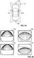
- Such 360 degree vision systemstypically utilize four wide angle cameras, one at the front of the vehicle, one at the rear and two at the sides. The outputs of these four cameras are displayed together on single display screen to provide a 360 degree image. See, for example, FIGS. 1A, 1B, and 1C , which show a vehicle 10 and the location of cameras 12 a - 12 d , respective camera images 14 a - 14 d , and 360 degree image 16 .
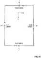
- the commercial 360 degree vision systemsare not seamless. Instead, to avoid having to deal with misalignment of and between the four cameras, the commercial systems basically display the images from the four cameras in four predetermined regions of the display, typically leaving buffer zones 17 between the four images as seen in FIG. 1C . In other words, the images from the four cameras are not seamlessly stitched together to provide a uniform composite 360 degree image 18 as shown in FIG. 1D , which is more visually appealing.
- An end of assembly line testermay be used to project predetermined targets in a controlled environment at known distances from the vehicle. Knowing the real physical position of various markers, it is possible to define a transfer function that maps camera pixel locations to real locations, and from this determine an offset to the nominal camera position.
- this end of line testing methoddoes not solve the problem of being able to independently calibrate the cameras in the field, where there is no controlled environment in which pre-designated markers are situated at known locations. Simply put, it is not possible to use end-of-line assembly line calibration based on predetermined targets in a controlled environment to calibrate a vehicular camera in the field.
- Each vehicular camerahas six degrees of freedom, three linear (up-down, right-left, forward-backward) and three rotational (roll, pitch, and yaw).
- three rotational degrees of freedomIn attempting to stitch together the images from the four cameras based on predetermined demarcation lines defined with respect to nominally positioned cameras, it was noticed that changes in the three rotational degrees of freedom in particular result in a noticeable visual distortion in the composite 360 degrees image. Thus, it is particularly desired to calibrate the cameras with respect to the three rotational degrees of freedom.
- the inventionpresents a method and system for dynamically ascertaining the position of a vehicular camera in the field, particularly with respect to its three rotational degrees of freedom, without manual intervention.
- the knowledge of the camera positionmay thus be used to calibrate the camera so as to seamlessly stitch together images from all four cameras. It will also be appreciated that the knowledge of camera position can also be used to calibrate the camera for a variety of other functions, for example, when one or more of the cameras are used for object detection, lane departure warning, automatic high beam control and other such driver assistance purposes.
- the inventiondynamically calibrates a vehicular camera to ascertain its position, in at least the three rotational degrees of freedom, with respect to a vehicular frame of reference or common coordinate system.
- a vehicular camerais independently calibrated using dynamic images obtained in the field.
- the calibrationis carried out by utilizing the principle of vanishing points, wherein parallel lines in a scene meet at a vanishing point.
- the inventionascertains a vanishing line based on a locus of such vanishing points.
- the position of the vanishing lineis correlated to the position of the vehicular camera, including in particular the angular positions thereof.
- FIG. 2Ashows a ground plane 20 , defined by X, Y coordinates.
- the ground planeis defined by the roadway.
- FIG. 3Ashows an image plane 20 ′ defined by x, y coordinates.
- the image plane 20 ′is provided in this example by the front facing camera 12 a.
- FIG. 2Aalso shows two lines 22 a , 22 b that are parallel with the Y-axis in the ground plane 20 . However, these two lines 22 a , 22 b will be seen in the image plane 20 ′ as non-parallel lines 22 a ′, 22 b ′ as shown in FIG. 3A . The non-parallel lines 22 a ′, 22 b ′ will meet at a central vanishing point VP 0 in the image plane 20 ′.
- non-parallel lines 32 a ′, 32 b ′ and 34 a ′, 34 b ′ in image plane 30 ′will be seen as non-parallel lines 32 a ′, 32 b ′ and 34 a ′, 34 b ′ in image plane 30 ′, as shown in FIG. 3B .
- the non-parallel lines 32 a ′, 32 b ′will meet at vanishing point VP 1 in the image plane 30 ′ and the non-parallel lines 34 a ′, 34 b ′ will meet at vanishing point VP 2 in the image plane 30 ′.
- the locus of vanishing points VP 0 , VP 1 , VP 2 in the image plane 30 ′will yield a vanishing line VL.
- the vanishing point VP 0will be located at a preordained pixel position (such as at the horizontal centre of the image) and the vanishing line VL will be perfectly horizontal in the image plane 30 ′ and located at a preordained vertical pixel height.
- FIG. 3Bshows the situation in the image plane when the front facing camera is situated at its nominal position.
- FIG. 2Cis identical to FIG. 2B
- the changes in the central vanishing point VP 0 and in the vanishing line VLcan be correlated in particular to changes in the angular positions or roll, pitch and yaw of the vehicular camera, enabling the camera to be independently calibrated.
- this aspect of the inventionselects a plurality of feature points in the scene and tracks the subsequent positions of these points in a set of image frames acquired from the camera video stream as the vehicle moves.
- feature point jthe base of a traffic sign pole on one side of the road
- feature point kthe base of a traffic sign pole on the other side of the road
- the pixel positions of these feature pointswill change over the subsequent image frames to yield, for example, vector J, comprising points (x 0 , y 0 ), (x 1 , y 1 ), . .
- the vehicleis shown moving in a straight line so as to enable the central vanishing point to be determined.
- the motion of the vehiclecan be approximated over relatively short distances (approximately 0.5 to 2 seconds of travel time, depending of vehicle speed) as a straight motion at an angle with respect to the ground Y-axis.
- one aspect of the inventionprovides a method of dynamically ascertaining the position or alignment of a vehicular camera relative to a vehicle to which the camera is attached.
- the methodincludes the steps of: (a) establishing a plurality of vehicular steering angle ranges; (b) acquiring a set of image frames in a video stream provided by the camera whilst the vehicle is in motion, the image frames defining an image plane; (c) measuring the steering angle of the vehicle and, for each steering angle range: (i) selecting a plurality of feature points in the image frames, (ii) tracking a motion trajectory of each selected feature point in the set of image frames, and (iii) determining a vanishing point in the image plane for the plurality of tracked motion trajectories; (d) determining a vanishing line in the image plane provided by the camera based on a locus of said vanishing points; and (e) determining the position or alignment of the camera based on the position of a central vanishing
- FIG. 1Ais a schematic diagram of a vehicle having front, rear, and side facing vehicular cameras and the fields of view provided thereby;
- FIG. 1Bis an example of images obtained by each of the four cameras shown in FIG. 1A ;
- FIG. 1Cis an image provided by a 360 degree vision system according to the prior art where the individual images provided by the cameras shown in FIG. 1B are not seamlessly stitched into a composite 360 degree image;
- FIG. 1Dis an image provided by a 360 degree vision system according to the preferred embodiment of the invention which seamlessly stitches together the individual images provided by the cameras as shown in FIG. 1B into a composite 360 degree image;
- FIG. 1Eis a diagram showing the relationships between individual camera coordinate systems and a vehicle coordinate system
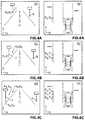
- FIG. 2Ais a diagram showing two lines parallel to a coordinate axis in a ground plane and FIG. 3A is a diagram showing the effect of these two parallel lines when projected onto an image plane provided by the camera in circumstances where the camera situated at its nominal position;
- FIG. 2Bis a diagram showing other parallel lines that are angled with respect to the coordinate axis in the ground plane of FIG. 2A and FIG. 3B is a diagram showing the effect of these other parallel lines when projected onto the image plane of FIG. 3A in circumstances where the camera situated at its nominal position;
- FIG. 2Cis identical to FIG. 2B
- FIG. 3Cis a diagram showing the sets of parallel lines in FIGS. 2A and 2B when projected onto the image plane provided by the camera in circumstances where the camera is NOT situated at its nominal position but has rotated;
- FIGS. 4A-4Care diagrams showing the motion trajectories of feature points over successive image frames in a video stream provided by the front camera;
- FIG. 5is a diagram showing vectors in the image plane derived from the motion trajectories of FIGS. 4A-4C ;
- FIGS. 6A-6Care diagrams showing the corresponding motion trajectories of the feature points in FIGS. 4A-4C in the ground plane;
- FIG. 7is a diagram showing vectors in the ground plane derived from the motion trajectories of FIGS. 6A-6C ;
- FIG. 8is a system block diagram from a hardware perspective of the 360 degree vision system
- FIG. 9is a block diagram of an online calibration algorithm executed by the 360 degree vision system for dynamically ascertaining the position, including angular rotations, of the front camera;
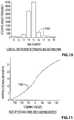
- FIG. 10is a histogram showing distribution of vehicle steering angle over normal driving conditions
- FIG. 11is a plot showing the size of steering angle bins over the range of steering angles
- FIG. 12is a flowchart of a vanishing point detection algorithm
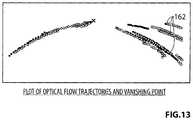
- FIG. 13is a diagram showing feature point motion trajectories in the image plane provided by the front camera
- FIG. 14is a diagram showing de-warped motion trajectories of FIG. 13 ;
- FIG. 15is a diagram showing linearly fitted, de-warped motion trajectories of FIG. 13 , and the location of a vanishing point based on the intersection of such trajectories;
- FIG. 16provides pseudo code for the algorithm shown in FIG. 12 ;
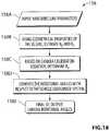
- FIG. 17is a flowchart of a vanishing line detection algorithm
- FIG. 18is a flowchart of a rotational angle estimation algorithm
- FIG. 19is a diagram showing various vanishing point and vanishing line parameters in the image plane which are used by the rotational angle estimation algorithm.
- ground planerefers to a real plane parallel to the roadway.
- image planerefers to a two-dimensional space provided as an output of a camera viewing a real three-dimensional space.
- plane at infinitymeans all points at infinity, and refers to a plane that is perpendicular to the ground plane.
- vanishing pointis a point at which parallel lines in the ground plane seem to converge in an image plane. If the camera is centered between two parallel lines in the ground plane which are parallel to the camera optical axis, the intersection of the two parallel lines is referred to as the “central vanishing point”.
- Principal pointrefers to the central vanishing point of a camera when the camera is at its nominal installed position and orientation. This principal point is an intrinsic camera parameter and provided as part of the manufacturing data.
- vanishing lineis a locus of estimated vanishing points.
- Camera rotational anglesare the angles that define the actual orientation of the camera.
- FIG. 1Eshows the position of the four cameras with respect to the vehicle coordinate system. The right hand system is assumed to be positive for the rotations.
- X axispitch or ⁇
- Y axisyaw or ⁇
- Z axisroll or ⁇
- the rotationsby definition, are not commutative and thus, the order in which the camera is rotated around the different axes is important. For our purpose, the camera is first rolled, followed by yaw and then pitch, making the order of rotations as Z axis (roll) ⁇ Y axis (yaw) ⁇ X axis (pitch).
- de-warpingrefers to a procedure for devolving distortions produced by a wide angle camera lens.
- the vehicular camera employed for the 360 degree composite imageis a very wide angle, omni-vision camera, so the original images are distorted.
- a de-warping procedure as known in the art per seis necessary to account for this distortion and to convert curvy trajectories to straight trajectories. Once the convergence point (vanishing point) is found, its coordinates are de-warped to give the final image coordinates.
- FIG. 8shows a hardware schematic for a preferred three-hundred-and-sixty degree vision system 100 , which includes the four vehicular cameras 12 a - 12 d , each of which includes a wide angle lens 102 coupled to an image sensor 104 , a memory 106 and a transmitter 108 .
- the camerasare coupled via the transmitters 108 to respective receivers 110 on a main electronic control unit (ECU) 112 .
- a floating point gate array (FPGA) 114functions as a multiplexer to provide one of the four camera video streams 116 (each stream comprising successive image frames captured by the camera at a rate of approximately 25-30 frames per second) to an output line 118 that is connected to a digital signal processor (DSP) 120 .
- DSPdigital signal processor
- the DSP 120in conjunction with an associated microcontroller 122 , processes the selected camera video stream and carries out the online calibration (OC) algorithms discussed in detail herein.
- the FPGA 114also provides a composite 360 degree view video output 124 to a display driver 126 based on stitching instructions provided by the DSP 120 via a command line 128 .
- the microcontroller 122is connected to the vehicle command area network (CAN) via a CAN transceiver 130 and thus can query the main vehicle controller (not shown) for information such as vehicle speed and steering angle.
- CANvehicle command area network
- main vehicle controllernot shown
- the OC algorithms according to the first aspect of the inventionare based on the concept of vanishing points because the estimation of the camera angles in these algorithms relies on the estimation of the vanishing line.
- the vanishing line in conjunction with the spatial position of the principal pointis used to determine the camera rotational angles.
- the OC algorithmutilizes the relative motion of the vehicle with respect to various feature points in order to generate motion trajectories to replicate the ideal situation in which there are parallel lines available in the input image. By selecting special features in the input images and tracking for short durations, these points move approximately parallel to the vehicle motion and thus are representative of parallel lines with respect to the coordinate system being considered. The intersection point of these trajectories lies on the vanishing point which is to be estimated.
- the trajectoriesWhen the vehicle turns, the trajectories have a different orientation depending on the angle of turn.
- the locus or collection of the various vanishing points in respect of the various steering anglescorresponds to different orientations of parallel lines, and enables the vanishing line to be estimated.
- FIG. 1Eshows a vehicle coordinate system that is used in conjunction with the example described in this publication.
- the vehicle X-axislies along the longitudinal axis of the vehicle.
- the vehicle Y-axislies along the cross-car direction or latitudinal axis of the vehicle.
- the vehicle Z-axisis the vertical axis (in/out of the page).
- the origin point (o)is midway along the front wheel drive axis.
- Each camera associated with the vehiclehas its own camera coordinate system where the X-axis always points to the right of the camera, the Y-axis always points away from the camera and the Z-axis is similar to the Z-axis of the vehicle coordinate system.
- the camera coordinate systemsare also illustrated in FIG. 1E .
- each camerais done so that its rotational angles are first estimated with respect to the camera coordinate system, where pitch ( ⁇ ), yaw ( ⁇ ) and roll ( ⁇ ) are the rotations around the X-, Y- and Z-axes of the camera coordinate system, respectively.
- pitch ( ⁇ ), yaw ( ⁇ ) and roll ( ⁇ )are the rotations around the X-, Y- and Z-axes of the camera coordinate system, respectively.
- these rotationscan be simply transformed to the equivalent rotations in the vehicle coordinate system as shown in Table 1 below.
- the rotations around the X-, Y- and Z-axes of the vehicle coordinate systemare termed as Rx, Ry and Rz, respectively.
- Table 2 belowshows an example of nominal angular positions of the front 12 a , rear 12 b and side facing cameras 12 c , 12 d in a sample vehicle. Note that the roll, pitch and yaw for each camera implies change about a different vehicular axis, e.g., for the front camera pitch is defined as the angle about the vehicle Y-axis and for the right side camera pitch is defined the angle about the vehicle X-axis.
- FIG. 9A system block diagram of an OC algorithm 150 for the front camera 12 a in accordance with the first aspect of the invention is shown in FIG. 9 .
- Inputs to the algorithm 150include: data confirming the active camera 12 (front 12 a , rear 12 b or side 12 c , 12 d camera); the intrinsic parameters (principal point, focal length, lens map) for the camera under consideration; and CAN bus data including the instantaneous vehicle speed and steering angle.
- the vehicle speed and steering angle informationis recorded for every image frame captured by the algorithm.
- the vanishing pointsare detected using a motion tracking method.
- the vanishing lineis estimated based on the locus or collection of the estimated vanishing points for the various steering angles.
- the estimated central vanishing point in conjunction with the vanishing lineleads to the final module 158 of the OC algorithm—the computation of the three camera rotational angles in the camera coordinate system, namely, ⁇ , ⁇ and ⁇ .
- the processing of successive image frames in step 152is conditioned upon two important inputs: steering angle and vehicle speed.
- the steering angleis one of the major inputs of the OC algorithm 150 .
- the inventorsascertained that during the different driving maneuvers the steering is held almost constant at different corresponding angles within a very small variation range for a computationally reasonable amount of time.
- FIG. 10shows a histogram of thirty consecutive frame sets lying in the same steering angle range observed during the normal driving along urban routes by multiple drivers.
- the steering anglehas been partitioned into bins 160 from ⁇ 180 degrees to +180 degrees in varying increments of 6 degrees or more for this experiment.
- FIG. 11shows an example of steering bin structure with linear increments for the bins 160 as the angles increase. Note that in alternative embodiments, nonlinear increments for the steering bins 160 may be used.
- the path of the vehicle with respect to any point being tracked on the groundcould be considered to be a straight line.
- the sharper the steering anglethe slower the movement of the car and the lesser the distance traveled in a curvature. This further helps to approximate the vehicle motion for very short durations by a straight path even for sharper turns.
- Thisallows for the detection of parallel trajectories in the same direction as the path of travel described by the wheels which is at an angle with respect to the vehicular coordinate system.
- a different set of vanishing pointscould be computed for these different set of parallel lines which are at different angles with respect to the vehicular coordinate axes and these vanishing points lie along the vanishing line.
- the change in the steering angle from the neutral (or 0 degree) locationcauses the wheels of the vehicle to move at an angle with respect to the body of the vehicle and thus any points tracked when steering is non-zero inscribe parallel trajectories which are at an angle to the X-axis of the vehicle coordinate system.
- the captured imagesare processed as a single set for small increments of steering angles.
- the estimation of the vanishing point within each steering binis thus conditioned upon the steering angle, whereby the input images are processed as a single set only if the steering angle is held within a particular range defined as steering bin. With any change in the steering out of the defined range, the previously computed trajectories are stored and the processing of a new set of images for the new steering bin is initiated
- the estimation of the vanishing point within each steering binis also conditioned upon the vehicle speed.
- the speed of the vehiclehas no effect in the path the trajectory follows in the image plane other than the fact the trajectory moves at a faster pixel rate across the frame at higher speeds. So, similar to the steering bin, if the speed values are held within a particular range, pre-defined in the algorithm, the speed bin remains constant. If the speed varies out of the defined range a new speed bin is introduced and several parameters such as tracking duration are updated. The new set of features is thus tracked according to the new set of parameters. For instance the increment in the speed bin causes the features to move faster and therefore the tracking duration will be shortened.
- a flow chart for the vanishing point detection module 154is shown in FIG. 12 .
- the main inputs 154 A to the vanishing point detection module 154include the image frames of the video stream, steering angle, and vehicle speed.
- the main goal of this moduleis to produce the vanishing point based on the available input data.
- a data structureis constructed for tracking trajectories across a variety of steering angles.
- the best features in a region of interest (ROI) that can lead to the determination of the vanishing pointare detected and stored.
- the ROIis close to the visible horizon line. Ideally the ROI should cover the road sides and not that much of the ground.
- steps 154 D- 154 Gvarious feature points are extracted and their motions tracked to generate trajectories.
- a pre-configured set of frameswhich is a function of speed and steering bin
- a new set of featuresare extracted and tracked over time.
- the tracking algorithmis based on motion vector estimation using block matching where, for each feature to be tracked in the current frame, a small 8 ⁇ 8 neighborhood around that feature is considered and the best possible match in a small window of pixels in the next frame is found. It is then assumed that the feature in the current frame has moved to the detected location in the next frame. Further information about block matching techniques may be found in Applicants' co-pending patent application PCT/CA2012/000057, filed Jan.
- step 154 Hthe collected trajectories are de-warped.
- Each trajectoryis then linearly fitted using robust regression techniques. If the fitted trajectories meet the criteria set by various threshold (such as sufficient length or time), they are saved. The intersection of these fitted trajectories gives the location of the vanishing point for each steering angle bin.
- FIG. 13shows an example in which trajectories 162 are shown in a warped image space (due to the wide angle lens used in the camera) and FIG. 14 shows trajectories 162 ′ in a de-warped space.
- FIG. 15shows the trajectories in the de-warped image linearly fitted to generate substantially linear trajectories 162 ′′, enabling a vanishing point VP to estimated. (Note that FIG. 15 is a mirror image of FIG. 14 utilizing a different scale.)
- Pseudo code for the vanishing point detection module 154is presented in FIG. 16 . Since the vanishing point is detected and recorded per different steering angle bin, and the threshold values as well as some processing data such as the location of ROI vary depending on the vehicle speed and steering angle, the vanishing point detection module stores the data necessary for the next module in a structured format called a ‘trajectory structure’. The number of elements in the trajectory structure depends on the number of steering bins. The most important elements of this structure are:
- the speed bin valueis checked and the trajectory structure is updated accordingly.
- the codechecks a few conditions and depending on the condition, different tasks are performed. If during the tracking process a speed bin change occurs, the trajectory structure is updated. The updated trajectory parameters are not applied to the tracking process, until the next set of tracking. This will not affect the performance since the speed bin does not vary in a shorter time frame than the tracking duration.
- FIG. 17A self-explanatory flowchart of the vanishing line detection module 156 is shown in FIG. 17 .
- This moduleis the intermediate step between the vanishing point and the camera rotational angle estimation modules 154 , 158 .
- the vanishing lineis estimated using a collection of vanishing points obtained during the different normal driving turning maneuvers of the vehicle. Since the estimated vanishing points lie on the visible vanishing line, the best vote vanishing points for each steering range can be used to estimate the vanishing line using a robust fitting scheme. The estimation of the vanishing point in each bin itself is preferably further refined by statistical voting. To estimate the vanishing line, a well-known robust regression technique in which the linear line parameters are iteratively estimated using least square method has been applied at step 156 D.
- FIG. 18shows a flowchart of the algorithm used in this module. Note that the initial output 158 E of this module is with respect to the camera coordinate system. The rotations in the camera coordinate system can then be transformed to the vehicle coordinate system as shown in Table 1.
- the vertical distance d 1 of this point to the vanishing line as well as the distance d 2 of a projection point to the central vanishing pointare computed.
- ⁇ and ⁇ anglesare estimated. Note that the X, Y, and Z coordinates are the camera coordinate system axes as shown in FIG. 1E .
- ⁇ and ⁇ anglesmap uniquely to the d 1 and d 2 distances, so in order to estimate these angles a lookup table is employed.
- This lookup tableis created by varying the front camera ⁇ and ⁇ angles and recording the resultant d 1 and d 2 distances for each combination of input ⁇ and ⁇ angles.
- Table 3A small portion of a sample lookup table is presented in Table 3 below.
- the d 1 and d 2 distancescan be used as indexes into the lookup table for the determination of the ⁇ and ⁇ angles. (It should also be understood that the exact relationship between ⁇ , ⁇ and d 1 , d 2 will differ depending on the particular arrangements and selection of cameras for each target vehicle.)
- the camera calibration equationis used to solve for the only unknown parameter.
- the camera calibration equationis defined as:
- [ x y z ]K ⁇ ⁇ R ⁇ ⁇ T ⁇ [ X Y Z ] ( 1 )
- X, Y, and Zare the camera coordinate system and the coordinates (x/z, y/z) are the image coordinates.
- the K parameteris the matrix of the camera intrinsic parameters as shown in equation (2):
- Equation (3)[ - f pixel ⁇ ⁇ Size 0 axis ⁇ ⁇ X 0 f pixel ⁇ ⁇ Size axis ⁇ ⁇ Y 0 0 1 ] ( 2 ) where f is the focal length, axisX and axisY are the coordinates of the principal point.
- the matrix Ris the combination of three rotational matrices shown in equation (3):
- the matrix Tis the translation matrix shown in equation (4):
- T[ 1 0 0 - t 1 0 1 0 - t 2 0 0 1 - t 3 ] ( 4 )
- t 1 , t 2 , and t 3are the translations along X, Y, and Z axes.
- the world coordinates of the central vanishing pointare independent of the camera's position with respect to the vehicle.
- the last rotation angle, roll or ⁇is estimated.
- the approach for the rear camera 12 bis similar to the approach for the front camera 12 a discussed above. However the ROI location will be different since the tracking direction is the opposite of the front camera. And the angle/distance lookup table will also be different due to the different geometries involved.
- the side cameras 12 c , 12 dwhich are installed in the mirrors on the side of the vehicle, also need to be calibrated online during the life cycle of the system 100 to assure the seamless stitching of the images captured by all four cameras. It is feasible to use an algorithm similar to the OC algorithm 150 for front and rear cameras to calibrate the side cameras.
Landscapes
- Engineering & Computer Science (AREA)
- Multimedia (AREA)
- Health & Medical Sciences (AREA)
- Biomedical Technology (AREA)
- General Health & Medical Sciences (AREA)
- Signal Processing (AREA)
- General Physics & Mathematics (AREA)
- Computer Vision & Pattern Recognition (AREA)
- Physics & Mathematics (AREA)
- Theoretical Computer Science (AREA)
- Image Analysis (AREA)
- Image Processing (AREA)
- Closed-Circuit Television Systems (AREA)
- Mechanical Engineering (AREA)
Abstract
Description
The present application is a continuation of U.S. patent application Ser. No. 15/161,711, filed May 23, 2016, now U.S. Pat. No. 10,202,077, which is a continuation of U.S. patent application Ser. No. 14/113,414, filed Oct. 23, 2013, now U.S. Pat. No. 9,357,208, which is a 371 national phase application of PCT Application No. PCT/CA2012/000056, filed Jan. 20, 2012, which claims priority to U.S. Provisional Application Ser. No. 61/478,711, filed Apr. 25, 2011, the contents of which are incorporated by reference herein in their entirety.
The invention relates to the field of vehicular cameras, and more particularly to methods and systems for dynamically calibrating the position or alignment of a vehicular camera in the field.
In an effort to provide drivers with a comprehensive view of their surroundings, vehicle manufacturers have recently proposed and marketed 360 degree vision systems which display a “bird's eye” view of the vehicle and its surroundings. Such 360 degree vision systems typically utilize four wide angle cameras, one at the front of the vehicle, one at the rear and two at the sides. The outputs of these four cameras are displayed together on single display screen to provide a 360 degree image. See, for example,FIGS. 1A, 1B, and 1C , which show avehicle 10 and the location ofcameras 12a-12d,respective camera images 14a-14d, and 360degree image 16.
A problem arises in attempting to stitch together the aforesaid camera images into a single composite image in that each camera is not absolutely fixed in position. There are tolerances during the manufacture of the cameras and assembly into the vehicle. In addition, and more importantly, the positioning of each camera will vary over the life of the vehicle as it is driven and subjected to the rigours of the real world. Vibrations from bumpy roads and door slams, the effects of car washes and repair and replacement of various parts, as well as the movement of the pivoting side view mirror housings, can all have an effect of the position (including angular orientation) of the vehicular cameras.
For this reason, the commercial 360 degree vision systems are not seamless. Instead, to avoid having to deal with misalignment of and between the four cameras, the commercial systems basically display the images from the four cameras in four predetermined regions of the display, typically leavingbuffer zones 17 between the four images as seen inFIG. 1C . In other words, the images from the four cameras are not seamlessly stitched together to provide a uniform composite 360degree image 18 as shown inFIG. 1D , which is more visually appealing.
It is possible to calibrate each camera when the vehicle leaves the factory production line. An end of assembly line tester may be used to project predetermined targets in a controlled environment at known distances from the vehicle. Knowing the real physical position of various markers, it is possible to define a transfer function that maps camera pixel locations to real locations, and from this determine an offset to the nominal camera position. However, this end of line testing method does not solve the problem of being able to independently calibrate the cameras in the field, where there is no controlled environment in which pre-designated markers are situated at known locations. Simply put, it is not possible to use end-of-line assembly line calibration based on predetermined targets in a controlled environment to calibrate a vehicular camera in the field.
Each vehicular camera has six degrees of freedom, three linear (up-down, right-left, forward-backward) and three rotational (roll, pitch, and yaw). In attempting to stitch together the images from the four cameras based on predetermined demarcation lines defined with respect to nominally positioned cameras, it was noticed that changes in the three rotational degrees of freedom in particular result in a noticeable visual distortion in the composite 360 degrees image. Thus, it is particularly desired to calibrate the cameras with respect to the three rotational degrees of freedom.
The invention presents a method and system for dynamically ascertaining the position of a vehicular camera in the field, particularly with respect to its three rotational degrees of freedom, without manual intervention. The knowledge of the camera position may thus be used to calibrate the camera so as to seamlessly stitch together images from all four cameras. It will also be appreciated that the knowledge of camera position can also be used to calibrate the camera for a variety of other functions, for example, when one or more of the cameras are used for object detection, lane departure warning, automatic high beam control and other such driver assistance purposes.
Generally speaking, the invention dynamically calibrates a vehicular camera to ascertain its position, in at least the three rotational degrees of freedom, with respect to a vehicular frame of reference or common coordinate system.
According to this aspect of the invention a vehicular camera is independently calibrated using dynamic images obtained in the field. The calibration is carried out by utilizing the principle of vanishing points, wherein parallel lines in a scene meet at a vanishing point. The invention ascertains a vanishing line based on a locus of such vanishing points. The position of the vanishing line is correlated to the position of the vehicular camera, including in particular the angular positions thereof.
The first aspect of the invention can be better appreciated with respect toFIGS. 2A-2C and 3A-3C .FIG. 2A shows aground plane 20, defined by X, Y coordinates. The ground plane is defined by the roadway.FIG. 3A shows animage plane 20′ defined by x, y coordinates. Theimage plane 20′ is provided in this example by thefront facing camera 12a.
Similarly, referring additionally toFIG. 2B , other sets of parallel lines such as32a,32band34a,34bthat are angled with respect to the Y-axis ground plane 30 will be seen asnon-parallel lines 32a′,32b′ and34a′,34b′ inimage plane 30′, as shown inFIG. 3B . Thenon-parallel lines 32a′,32b′ will meet at vanishing point VP1in theimage plane 30′ and thenon-parallel lines 34a′,34b′ will meet at vanishing point VP2in theimage plane 30′. The locus of vanishing points VP0, VP1, VP2in theimage plane 30′ will yield a vanishing line VL. In circumstances where the camera is perfectly aligned with no rotational error as shown inFIG. 3B , the vanishing point VP0will be located at a preordained pixel position (such as at the horizontal centre of the image) and the vanishing line VL will be perfectly horizontal in theimage plane 30′ and located at a preordained vertical pixel height. Thus,FIG. 3B shows the situation in the image plane when the front facing camera is situated at its nominal position.
However, if the position including the rotational angles of the front camera has shifted then, as shown in the ground andimage planes FIGS. 2C, and 3C , the same ground plane conditions (FIG. 2C is identical toFIG. 2B ) will generate shifted vanishing points VP0′, VP1′, VP2′ and a shifted (and angled with respect to the horizontal) vanishing line VL′ in the image plane. The changes in the central vanishing point VP0and in the vanishing line VL can be correlated in particular to changes in the angular positions or roll, pitch and yaw of the vehicular camera, enabling the camera to be independently calibrated.
To find parallel lines in a dynamic situation where the vehicle is in motion, this aspect of the invention selects a plurality of feature points in the scene and tracks the subsequent positions of these points in a set of image frames acquired from the camera video stream as the vehicle moves. Thus, for example, as shown in the schematic diagrams ofFIGS. 4A-4C , feature point j (the base of a traffic sign pole on one side of the road) and feature point k (the base of a traffic sign pole on the other side of the road) are tracked at subsequent image frames40,42,44. The pixel positions of these feature points will change over the subsequent image frames to yield, for example, vector J, comprising points (x0, y0), (x1, y1), . . . (xn, yn), in respect of feature point j, and vector K in respect of feature point k. The vectors J and K are graphed in animage plane 50 inFIG. 5 , and can be extrapolated to ascertain the central vanishing point VP0in theimage plane 50. The corresponding situation is shown in ground planes60,62,64 ofFIGS. 6A-6C , from which it should be appreciated that the motion of the vehicle relative to the feature points can be utilized to extract parallel lines J and K in theground plane 70 as shown inFIG. 7 .
In the situation just discussed, the vehicle is shown moving in a straight line so as to enable the central vanishing point to be determined. However, when the vehicle turns as a result of a change in its steering angle, the motion of the vehicle can be approximated over relatively short distances (approximately 0.5 to 2 seconds of travel time, depending of vehicle speed) as a straight motion at an angle with respect to the ground Y-axis. Repeating the foregoing process of extracting and tracking the trajectories of feature points for various steering angle ranges as the vehicle moves will enable other vanishing points to be determined, hence enabling the determination of the vanishing line.
Similar conditions and circumstances exist for the rear and side camera, but the exact relationship between changes in camera angular position and shifts in the central vanishing point and vanishing will differ.
From the foregoing then, it will be appreciated that one aspect of the invention provides a method of dynamically ascertaining the position or alignment of a vehicular camera relative to a vehicle to which the camera is attached. The method includes the steps of: (a) establishing a plurality of vehicular steering angle ranges; (b) acquiring a set of image frames in a video stream provided by the camera whilst the vehicle is in motion, the image frames defining an image plane; (c) measuring the steering angle of the vehicle and, for each steering angle range: (i) selecting a plurality of feature points in the image frames, (ii) tracking a motion trajectory of each selected feature point in the set of image frames, and (iii) determining a vanishing point in the image plane for the plurality of tracked motion trajectories; (d) determining a vanishing line in the image plane provided by the camera based on a locus of said vanishing points; and (e) determining the position or alignment of the camera based on the position of a central vanishing point (determined when the steering angle range encompasses 0 degrees) and the vanishing line.
The foregoing and other aspects of the invention will be better understood with respect to the attached drawings, wherein:
In this document, unless the context dictates otherwise, the following terms have the following meanings:
“ground plane” refers to a real plane parallel to the roadway.
“image plane” refers to a two-dimensional space provided as an output of a camera viewing a real three-dimensional space.
“plane at infinity” means all points at infinity, and refers to a plane that is perpendicular to the ground plane.
“horizon line” is the intersection of the ground plane with the plane at infinity.
“vanishing point” is a point at which parallel lines in the ground plane seem to converge in an image plane. If the camera is centered between two parallel lines in the ground plane which are parallel to the camera optical axis, the intersection of the two parallel lines is referred to as the “central vanishing point”.
“principal point” refers to the central vanishing point of a camera when the camera is at its nominal installed position and orientation. This principal point is an intrinsic camera parameter and provided as part of the manufacturing data.
“vanishing line” is a locus of estimated vanishing points.
“camera rotational angles” are the angles that define the actual orientation of the camera.FIG. 1E shows the position of the four cameras with respect to the vehicle coordinate system. The right hand system is assumed to be positive for the rotations. Consider the total rotation of each camera to be defined in terms of its rotation around the individual camera coordinates: X axis (pitch or α), Y axis (yaw or β) and Z axis (roll or γ). The rotations, by definition, are not commutative and thus, the order in which the camera is rotated around the different axes is important. For our purpose, the camera is first rolled, followed by yaw and then pitch, making the order of rotations as Z axis (roll)→Y axis (yaw)→X axis (pitch).
“de-warping” refers to a procedure for devolving distortions produced by a wide angle camera lens. In the preferred embodiment the vehicular camera employed for the 360 degree composite image is a very wide angle, omni-vision camera, so the original images are distorted. A de-warping procedure as known in the art per se is necessary to account for this distortion and to convert curvy trajectories to straight trajectories. Once the convergence point (vanishing point) is found, its coordinates are de-warped to give the final image coordinates.
Themicrocontroller 122 is connected to the vehicle command area network (CAN) via aCAN transceiver 130 and thus can query the main vehicle controller (not shown) for information such as vehicle speed and steering angle.
As summarized above, the OC algorithms according to the first aspect of the invention are based on the concept of vanishing points because the estimation of the camera angles in these algorithms relies on the estimation of the vanishing line. In order to determine the vanishing line, it is necessary to estimate vanishing points corresponding to different orientations of parallel lines in the image. The vanishing line in conjunction with the spatial position of the principal point is used to determine the camera rotational angles.
Ideally, in order to collect various vanishing points in different orientations, there should be various parallel lines with different orientations in the corresponding ground plane. However this is not available in reality since the surrounding view or scene is not a controlled environment. Additionally there exist various external environmental factors preventing a perfect projection of parallel lines into the image plane. Thus the OC algorithm utilizes the relative motion of the vehicle with respect to various feature points in order to generate motion trajectories to replicate the ideal situation in which there are parallel lines available in the input image. By selecting special features in the input images and tracking for short durations, these points move approximately parallel to the vehicle motion and thus are representative of parallel lines with respect to the coordinate system being considered. The intersection point of these trajectories lies on the vanishing point which is to be estimated. When the vehicle turns, the trajectories have a different orientation depending on the angle of turn. The locus or collection of the various vanishing points in respect of the various steering angles corresponds to different orientations of parallel lines, and enables the vanishing line to be estimated.
I. Coordinate System
| TABLE 1 | |||||
| Camera | Rz (degree) | Ry(degree) | Rx(degree) | ||
| Front | γ + 90 | α | −β | ||
| Left | γ + 180 | −β | −α | ||
| Rear | γ + 270 | −α | β | ||
| Right | γ | β | α | ||
Table 2 below shows an example of nominal angular positions of the front12a, rear12bandside facing cameras
| TABLE 2 | |||||
| Camera | Rz (degree) | Ry(degree) | Rx(degree) | ||
| Front | 90 | 62 | 0 | ||
| Left | 180 | 0 | −12 | ||
| Rear | 270 | −45 | 0 | ||
| 0 | 0 | 12 | |||
II. Front Camera
A system block diagram of anOC algorithm 150 for thefront camera 12ain accordance with the first aspect of the invention is shown inFIG. 9 . Inputs to thealgorithm 150 include: data confirming the active camera12 (front 12a, rear12borside initial module 152 the vehicle speed and steering angle information is recorded for every image frame captured by the algorithm. In afirst module 154, the vanishing points are detected using a motion tracking method. In a followingmodule 156, the vanishing line is estimated based on the locus or collection of the estimated vanishing points for the various steering angles. The estimated central vanishing point in conjunction with the vanishing line leads to thefinal module 158 of the OC algorithm—the computation of the three camera rotational angles in the camera coordinate system, namely, α, β and γ.
A. Inputs
The processing of successive image frames instep 152 is conditioned upon two important inputs: steering angle and vehicle speed. The steering angle is one of the major inputs of theOC algorithm 150. Using steering angle data captured during approximately ten hours of normal driving in a variety of scenarios using multiple drivers and with no special maneuvers, the inventors ascertained that during the different driving maneuvers the steering is held almost constant at different corresponding angles within a very small variation range for a computationally reasonable amount of time.FIG. 10 shows a histogram of thirty consecutive frame sets lying in the same steering angle range observed during the normal driving along urban routes by multiple drivers. The steering angle has been partitioned intobins 160 from −180 degrees to +180 degrees in varying increments of 6 degrees or more for this experiment. The way the angles are partitioned is determined by an external function in which the central angles are (−6 to +6 degrees) divided into two central bins with a width of six degrees. The bins have symmetrical structure. The width of the bins for positive and negative angles is the same. The larger the angle becomes the wider the corresponding steering bin.FIG. 11 shows an example of steering bin structure with linear increments for thebins 160 as the angles increase. Note that in alternative embodiments, nonlinear increments for thesteering bins 160 may be used.
Furthermore, although with a change in the steering angle the vehicle inscribes a circle, for a very short duration (˜<1-2 sec) the path of the vehicle with respect to any point being tracked on the ground could be considered to be a straight line. The sharper the steering angle, the slower the movement of the car and the lesser the distance traveled in a curvature. This further helps to approximate the vehicle motion for very short durations by a straight path even for sharper turns. This allows for the detection of parallel trajectories in the same direction as the path of travel described by the wheels which is at an angle with respect to the vehicular coordinate system. Thus, a different set of vanishing points could be computed for these different set of parallel lines which are at different angles with respect to the vehicular coordinate axes and these vanishing points lie along the vanishing line.
The change in the steering angle from the neutral (or 0 degree) location causes the wheels of the vehicle to move at an angle with respect to the body of the vehicle and thus any points tracked when steering is non-zero inscribe parallel trajectories which are at an angle to the X-axis of the vehicle coordinate system. To maintain linearity and constancy of the inclination of the trajectories, the captured images are processed as a single set for small increments of steering angles.
The estimation of the vanishing point within each steering bin is thus conditioned upon the steering angle, whereby the input images are processed as a single set only if the steering angle is held within a particular range defined as steering bin. With any change in the steering out of the defined range, the previously computed trajectories are stored and the processing of a new set of images for the new steering bin is initiated
The estimation of the vanishing point within each steering bin is also conditioned upon the vehicle speed. The speed of the vehicle has no effect in the path the trajectory follows in the image plane other than the fact the trajectory moves at a faster pixel rate across the frame at higher speeds. So, similar to the steering bin, if the speed values are held within a particular range, pre-defined in the algorithm, the speed bin remains constant. If the speed varies out of the defined range a new speed bin is introduced and several parameters such as tracking duration are updated. The new set of features is thus tracked according to the new set of parameters. For instance the increment in the speed bin causes the features to move faster and therefore the tracking duration will be shortened.
B. Vanishing Point Detection
A flow chart for the vanishingpoint detection module 154 is shown inFIG. 12 . Themain inputs 154A to the vanishingpoint detection module 154 include the image frames of the video stream, steering angle, and vehicle speed. The main goal of this module is to produce the vanishing point based on the available input data.
In aninitial step 154B a data structure is constructed for tracking trajectories across a variety of steering angles. In a following step154C the best features in a region of interest (ROI) that can lead to the determination of the vanishing point are detected and stored. For the front-facing camera, the ROI is close to the visible horizon line. Ideally the ROI should cover the road sides and not that much of the ground.
In the followingsteps 154D-154G, various feature points are extracted and their motions tracked to generate trajectories. For a pre-configured set of frames (which is a function of speed and steering bin), a new set of features are extracted and tracked over time. The tracking algorithm is based on motion vector estimation using block matching where, for each feature to be tracked in the current frame, a small 8×8 neighborhood around that feature is considered and the best possible match in a small window of pixels in the next frame is found. It is then assumed that the feature in the current frame has moved to the detected location in the next frame. Further information about block matching techniques may be found in Applicants' co-pending patent application PCT/CA2012/000057, filed Jan. 20, 2012 and entitled “Image Processing Method for Detecting Objects Using Relative Motion” and published Nov. 1, 2012 as International Publication No. WO 2012/145819, the contents of which are incorporated by reference herein in their entirety. The collected trajectories are stored and their spatial properties are evaluated per frame set insteps 154H and154I.
More particularly, instep 154H, the collected trajectories are de-warped. Each trajectory is then linearly fitted using robust regression techniques. If the fitted trajectories meet the criteria set by various threshold (such as sufficient length or time), they are saved. The intersection of these fitted trajectories gives the location of the vanishing point for each steering angle bin. For instance,FIG. 13 shows an example in whichtrajectories 162 are shown in a warped image space (due to the wide angle lens used in the camera) andFIG. 14 shows trajectories 162′ in a de-warped space.FIG. 15 shows the trajectories in the de-warped image linearly fitted to generate substantiallylinear trajectories 162″, enabling a vanishing point VP to estimated. (Note thatFIG. 15 is a mirror image ofFIG. 14 utilizing a different scale.)
Pseudo code for the vanishingpoint detection module 154 is presented inFIG. 16 . Since the vanishing point is detected and recorded per different steering angle bin, and the threshold values as well as some processing data such as the location of ROI vary depending on the vehicle speed and steering angle, the vanishing point detection module stores the data necessary for the next module in a structured format called a ‘trajectory structure’. The number of elements in the trajectory structure depends on the number of steering bins. The most important elements of this structure are:
(a) Steering bin width. Since it is not feasible to account for each single angle, the bins have been designed to include a group of angles. The range of angles allocated to each bin is determined by an external function.
(b) Pre-configured set of frames. The duration for which each feature is tracked is determined by this number of frames. After reaching this number a new set of features are selected and tracked. The estimation of vanishing points is also conditioned upon the number of frames. The duration of the tracking is dependent upon the steering angle range in consideration, with a sharper steering angle being accounted for by a shorter track length translated into smaller number of frames.
(c) ROI location. The image region in which the initial features are selected.
(d) Number of features threshold per trajectory. The minimum number of features each trajectory must have in order to be qualified for further processing.
(e) Number of trajectories for estimation of vanishing point. A minimum number of trajectories are preferably needed to find the vanishing point.
As shown, at the initial stage, the speed bin value is checked and the trajectory structure is updated accordingly. After this step, the code checks a few conditions and depending on the condition, different tasks are performed. If during the tracking process a speed bin change occurs, the trajectory structure is updated. The updated trajectory parameters are not applied to the tracking process, until the next set of tracking. This will not affect the performance since the speed bin does not vary in a shorter time frame than the tracking duration.
C. Vanishing Line Detection
A self-explanatory flowchart of the vanishingline detection module 156 is shown inFIG. 17 . This module is the intermediate step between the vanishing point and the camera rotationalangle estimation modules step 156D.
D. Rotation Angle Estimation
Once the vanishing line is estimated, the parameters of the vanishing line are used as inputs to the rotationalangle estimation module 158. The output of this module is the final OC output—the camera rotational angles.FIG. 18 shows a flowchart of the algorithm used in this module. Note that theinitial output 158E of this module is with respect to the camera coordinate system. The rotations in the camera coordinate system can then be transformed to the vehicle coordinate system as shown in Table 1.
Referring additionally toFIG. 19 , knowing the location of the principal point, the vertical distance d1of this point to the vanishing line as well as the distance d2of a projection point to the central vanishing point are computed. Based on the geometrical relationship between the vanishing line and the actual camera angles, α and β angles are estimated. Note that the X, Y, and Z coordinates are the camera coordinate system axes as shown inFIG. 1E .
It has been discovered that the α and β angles map uniquely to the d1and d2distances, so in order to estimate these angles a lookup table is employed. This lookup table is created by varying the front camera α and β angles and recording the resultant d1and d2distances for each combination of input α and β angles. A small portion of a sample lookup table is presented in Table 3 below. The d1and d2distances can be used as indexes into the lookup table for the determination of the α and β angles. (It should also be understood that the exact relationship between α, β and d1, d2will differ depending on the particular arrangements and selection of cameras for each target vehicle.)
| TABLE 3 | |||||
| d1 | d2 | α | β | ||
| 152.5087 | 3.2576 | 62.6000 | −0.5000 | ||
| 152.5114 | 2.6061 | 62.6000 | −0.4000 | ||
| 152.5134 | 1.9546 | 62.6000 | −0.3000 | ||
| 152.5149 | 1.3030 | 62.6000 | −0.2000 | ||
| 152.5158 | 0.6515 | 62.6000 | −0.1000 | ||
| 152.5161 | 0.0000 | 62.6000 | 0 | ||
| 152.5158 | 0.6515 | 62.6000 | 0.1000 | ||
| 152.5149 | 1.3030 | 62.6000 | 0.2000 | ||
| 152.5134 | 1.9546 | 62.6000 | 0.3000 | ||
| 152.5114 | 2.6061 | 62.6000 | 0.4000 | ||
| 152.5087 | 3.2576 | 62.6000 | 0.5000 | ||
To find the roll angle or γ, the camera calibration equation is used to solve for the only unknown parameter. The camera calibration equation is defined as:
where X, Y, and Z are the camera coordinate system and the coordinates (x/z, y/z) are the image coordinates. The K parameter is the matrix of the camera intrinsic parameters as shown in equation (2):
where f is the focal length, axisX and axisY are the coordinates of the principal point. The matrix R is the combination of three rotational matrices shown in equation (3):
where parameters α, β, and γ represent the angles of rotation around camera coordinate system axes X, Y, and Z, respectively. The matrix T is the translation matrix shown in equation (4):
where t1, t2, and t3are the translations along X, Y, and Z axes. Assuming the world coordinates of the central vanishing point on the ground plane of the camera coordinate system to be X=0, Y=∞, Z=0, the projection in the image plane (cvpX=image x coordinate of the central vanishing point in the image plane) is already estimated. Thus, for the projection of the central vanishing point onto the image plane, x=cvpX and y=cvpY. Note that the world coordinates of the central vanishing point are independent of the camera's position with respect to the vehicle.
Replacing K, R, and T in equation (1) with known α, β, X, Y, Z, x, and y, results in equation (5) in which only the angle γ in Ryis unknown.
Acos γ+Bsin γ=C
where,
A=fsin α sin β
B=fcos α
C=(cvpX−axisX)sin α cos β (5)
Acos γ+Bsin γ=C
where,
A=fsin α sin β
B=fcos α
C=(cvpX−axisX)sin α cos β (5)
By solving the sinusoidal equation, the last rotation angle, roll or γ, is estimated.
III. Rear Camera
The approach for therear camera 12bis similar to the approach for thefront camera 12adiscussed above. However the ROI location will be different since the tracking direction is the opposite of the front camera. And the angle/distance lookup table will also be different due to the different geometries involved.
IV. Side Camera
Theside cameras system 100 to assure the seamless stitching of the images captured by all four cameras. It is feasible to use an algorithm similar to theOC algorithm 150 for front and rear cameras to calibrate the side cameras.
Those skilled in the art will understand that a variety of modifications may be made to the particular embodiments discussed herein without departing from the fair scope of the invention as defined by the following claims.
Claims (24)
1. A method of dynamically calibrating without manual intervention a forward viewing vehicular camera with respect to its three rotational degrees of freedom, the method comprising:
disposing a forward viewing camera at a vehicle, the forward viewing camera, when disposed at the vehicle, having a field of view exterior and forward of the vehicle;
providing a control having a processor operable for processing image data captured by the forward viewing camera;
driving the vehicle so that the vehicle is in motion;
wherein driving the vehicle comprises steering the vehicle so as to establish a plurality of vehicle steering angles;
operating the forward viewing camera to acquire multiple frames of image data captured by the forward viewing camera while the vehicle is in motion and steered within at least two ranges of steering angles, wherein each frame of captured image data defines an image plane having a horizontal axis and a vertical axis;
determining, via processing at the control of a first image frame of image data captured by the forward viewing camera, first and second feature points in the first image frame of captured image data;
tracking, via processing at the control of image frames of image data captured by the forward viewing camera subsequent to the first image frame, a motion trajectory of the first feature point and of the second feature point while the vehicle is moving and steered within a first range of steering angles;
determining a first vanishing point based on the tracked first feature point and second feature point;
determining, via processing at the control of a second image frame of image data captured by the forward viewing camera, third and fourth feature points in the second image frame of captured image data;
tracking, via processing at the control of image frames of image data captured by the forward viewing camera subsequent to the second image frame, a motion trajectory of the third feature point and of the fourth feature point while the vehicle is moving and steered within a second range of steering angles that is different from the first range of steering angles;
determining a second vanishing point based on the tracked third feature point and fourth feature point;
determining a vanishing line based on the first and second vanishing points;
determining whether the vanishing line is non-parallel to the horizontal axis of the image plane; and
responsive to determining that the vanishing line is non-parallel to the horizontal axis of the image plane, adjusting at least one selected from the group consisting of pitch of the forward viewing camera, roll of the forward viewing camera and yaw of the forward viewing camera to correct for rotational misalignment of the forward viewing camera.
2. The method ofclaim 1 , wherein the first range of steering angles comprises steering angles close to or at zero degrees such that the vehicle is traveling in a straight line.
3. The method ofclaim 2 , wherein, when the vehicle turns, motion of the vehicle is approximated as straight line motion for a travel time of 0.5 to 2 seconds.
4. The method ofclaim 3 , wherein approximation to straight line motion when the vehicle turns is vehicle speed dependent.
5. The method ofclaim 4 , wherein approximation to straight line motion when the vehicle turns occurs for 0.5 to 2 seconds of travel time after turning from straight line travel.
6. The method ofclaim 1 , wherein image data captured by the forward viewing camera is processed at the control for at least one selected from the group consisting of (i) object detection, (ii) lane departure warning and (iii) automatic high beam control.
7. The method ofclaim 1 , wherein the forward viewing camera comprises a wide angle lens, and wherein the method comprises removing distortion caused by use of the wide angle lens.
8. The method ofclaim 1 , wherein the forward viewing camera is part of a multi-camera vision system of the vehicle.
9. The method ofclaim 8 , wherein the multi-camera vision system of the vehicle comprises the forward viewing camera and three other vehicular cameras.
10. The method ofclaim 9 , wherein image data captured by at least two of the four cameras of the multi-camera vision system is stitched together to provide a composite image for display to a driver of the vehicle.
11. The method ofclaim 1 , comprising receiving at the control vehicle data via a communication bus of the vehicle.
12. The method ofclaim 11 , wherein the received vehicle data includes vehicle speed data and vehicle steering angle data.
13. The method ofclaim 11 , wherein the communication bus of the vehicle comprised a CAN bus.
14. The method ofclaim 13 , wherein the forward viewing camera captures at least 25 frames of image data per second.
15. A method of dynamically calibrating without manual intervention a forward viewing vehicular camera with respect to its three rotational degrees of freedom, the method comprising:
disposing a forward viewing camera at a vehicle, the forward viewing camera, when disposed at the vehicle, having a field of view exterior and forward of the vehicle;
providing a control having a processor operable for processing image data captured by the forward viewing camera;
driving the vehicle so that the vehicle is in motion;
wherein driving the vehicle comprises steering the vehicle so as to establish a plurality of vehicle steering angles;
operating the forward viewing camera to acquire multiple frames of image data captured by the forward viewing camera while the vehicle is in motion and steered within at least two ranges of steering angles, wherein each frame of captured image data defines an image plane having a horizontal axis and a vertical axis;
determining, via processing at the control of a first image frame of image data captured by the forward viewing camera, first and second feature points in the first image frame of captured image data;
tracking, via processing at the control of image frames of image data captured by the forward viewing camera subsequent to the first image frame, a motion trajectory of the first feature point and of the second feature point while the vehicle is moving and steered within a first range of steering angles, wherein the first range of steering angles comprises steering angles close to or at zero degrees such that the vehicle is traveling in a straight line;
determining a first vanishing point based on the tracked first feature point and second feature point;
determining, via processing at the control of a second image frame of image data captured by the forward viewing camera, third and fourth feature points in the second image frame of captured image data;
tracking, via processing at the control of image frames of image data captured by the forward viewing camera subsequent to the second image frame, a motion trajectory of the third feature point and of the fourth feature point while the vehicle is moving and steered within a second range of steering angles, wherein the second range of steering angles comprises steering angles that do not include angles close to or at zero degrees such that the vehicle is traveling along a curve;
determining a second vanishing point based on the tracked third feature point and fourth feature point;
determining a vanishing line based on the first and second vanishing points;
determining whether the vanishing line is non-parallel to the horizontal axis of the image plane; and
responsive to determining that the vanishing line is non-parallel to the horizontal axis of the image plane, adjusting at least one selected from the group consisting of pitch of the forward viewing camera, roll of the forward viewing camera and yaw of the forward viewing camera to correct for rotational misalignment of the forward viewing camera.
16. The method ofclaim 15 , wherein image data captured by the forward viewing camera is processed at the control for at least one selected from the group consisting of (i) object detection, (ii) lane departure warning and (iii) automatic high beam control.
17. The method ofclaim 15 , wherein the forward viewing camera comprises a wide angle lens, and wherein the method comprises removing distortion caused by use of the wide angle lens.
18. The method ofclaim 15 , wherein the forward viewing camera is part of a multi-camera vision system of the vehicle, and wherein the multi-camera vision system of the vehicle comprises the forward viewing camera and three other vehicular cameras.
19. The method ofclaim 18 , wherein image data captured by at least two of the four cameras of the multi-camera vision system is stitched together to provide a composite image for display to a driver of the vehicle.
20. The method ofclaim 15 , comprising receiving at the control vehicle data via a communication bus of the vehicle, and wherein the received vehicle data includes vehicle speed data and vehicle steering angle data.
21. A method of dynamically calibrating without manual intervention a forward viewing vehicular camera with respect to its three rotational degrees of freedom, the method comprising:
disposing a forward viewing camera at a vehicle, the forward viewing camera, when disposed at the vehicle, having a field of view exterior and forward of the vehicle;
providing a control having a processor operable for processing image data captured by the forward viewing camera;
driving the vehicle so that the vehicle is in motion;
wherein driving the vehicle comprises steering the vehicle so as to establish a plurality of vehicle steering angles;
operating the forward viewing camera to acquire multiple frames of image data captured by the forward viewing camera while the vehicle is in motion and steered within at least two ranges of steering angles, wherein each frame of captured image data defines an image plane having a horizontal axis and a vertical axis;
determining, via processing at the control of a first image frame of image data captured by the forward viewing camera, first and second feature points in the first image frame of captured image data;
tracking, via processing at the control of image frames of image data captured by the forward viewing camera subsequent to the first image frame, a motion trajectory of the first feature point and of the second feature point while the vehicle is moving and steered within a first range of steering angles;
determining a first vanishing point based on the tracked first feature point and second feature point;
determining, via processing at the control of a second image frame of image data captured by the forward viewing camera, third and fourth feature points in the second image frame of captured image data;
tracking, via processing at the control of image frames of image data captured by the forward viewing camera subsequent to the second image frame, a motion trajectory of the third feature point and of the fourth feature point while the vehicle is moving and steered within a second range of steering angles that is different from the first range of steering angles;
determining a second vanishing point based on the tracked third feature point and fourth feature point;
determining a vanishing line based on the first and second vanishing points;
determining whether the vanishing line is non-parallel to the horizontal axis of the image plane;
receiving at the control vehicle data via a communication bus of the vehicle, and wherein the received vehicle data includes vehicle speed data and vehicle steering angle data;
responsive to determining that the vanishing line is non-parallel to the horizontal axis of the image plane, adjusting at least one selected from the group consisting of pitch of the forward viewing camera, roll of the forward viewing camera and yaw of the forward viewing camera to correct for rotational misalignment of the forward viewing camera; and
wherein image data captured by the forward viewing camera is processed at the control for at least one selected from the group consisting of (i) object detection, (ii) lane departure warning and (iii) automatic high beam control.
22. The method ofclaim 21 , wherein, when the vehicle turns, motion of the vehicle is approximated as straight line motion for a travel time of 0.5 to 2 seconds.
23. The method ofclaim 22 , wherein approximation to straight line motion when the vehicle turns is vehicle speed dependent.
24. The method ofclaim 23 , wherein, when the vehicle turns from steering angles close to or at zero degrees, approximation to straight line motion occurs for 0.5 to 2 seconds of travel time after the vehicle turns.
Priority Applications (3)
| Application Number | Priority Date | Filing Date | Title |
|---|---|---|---|
| US16/266,178US10640041B2 (en) | 2011-04-25 | 2019-02-04 | Method for dynamically calibrating vehicular cameras |
| US15/929,460US11007934B2 (en) | 2011-04-25 | 2020-05-04 | Method for dynamically calibrating a vehicular camera |
| US17/302,933US11554717B2 (en) | 2011-04-25 | 2021-05-17 | Vehicular vision system that dynamically calibrates a vehicular camera |
Applications Claiming Priority (5)
| Application Number | Priority Date | Filing Date | Title |
|---|---|---|---|
| US201161478711P | 2011-04-25 | 2011-04-25 | |
| PCT/CA2012/000056WO2012145818A1 (en) | 2011-04-25 | 2012-01-20 | Method and system for dynamically calibrating vehicular cameras |
| US201314113414A | 2013-10-23 | 2013-10-23 | |
| US15/161,711US10202077B2 (en) | 2011-04-25 | 2016-05-23 | Method for dynamically calibrating vehicular cameras |
| US16/266,178US10640041B2 (en) | 2011-04-25 | 2019-02-04 | Method for dynamically calibrating vehicular cameras |
Related Parent Applications (1)
| Application Number | Title | Priority Date | Filing Date |
|---|---|---|---|
| US15/161,711ContinuationUS10202077B2 (en) | 2011-04-25 | 2016-05-23 | Method for dynamically calibrating vehicular cameras |
Related Child Applications (1)
| Application Number | Title | Priority Date | Filing Date |
|---|---|---|---|
| US15/929,460ContinuationUS11007934B2 (en) | 2011-04-25 | 2020-05-04 | Method for dynamically calibrating a vehicular camera |
Publications (2)
| Publication Number | Publication Date |
|---|---|
| US20190168670A1 US20190168670A1 (en) | 2019-06-06 |
| US10640041B2true US10640041B2 (en) | 2020-05-05 |
Family
ID=47071510
Family Applications (5)
| Application Number | Title | Priority Date | Filing Date |
|---|---|---|---|
| US14/113,414Active2032-10-10US9357208B2 (en) | 2011-04-25 | 2012-01-20 | Method and system for dynamically calibrating vehicular cameras |
| US15/161,711Active2032-09-02US10202077B2 (en) | 2011-04-25 | 2016-05-23 | Method for dynamically calibrating vehicular cameras |
| US16/266,178ActiveUS10640041B2 (en) | 2011-04-25 | 2019-02-04 | Method for dynamically calibrating vehicular cameras |
| US15/929,460ActiveUS11007934B2 (en) | 2011-04-25 | 2020-05-04 | Method for dynamically calibrating a vehicular camera |
| US17/302,933Active2032-02-21US11554717B2 (en) | 2011-04-25 | 2021-05-17 | Vehicular vision system that dynamically calibrates a vehicular camera |
Family Applications Before (2)
| Application Number | Title | Priority Date | Filing Date |
|---|---|---|---|
| US14/113,414Active2032-10-10US9357208B2 (en) | 2011-04-25 | 2012-01-20 | Method and system for dynamically calibrating vehicular cameras |
| US15/161,711Active2032-09-02US10202077B2 (en) | 2011-04-25 | 2016-05-23 | Method for dynamically calibrating vehicular cameras |
Family Applications After (2)
| Application Number | Title | Priority Date | Filing Date |
|---|---|---|---|
| US15/929,460ActiveUS11007934B2 (en) | 2011-04-25 | 2020-05-04 | Method for dynamically calibrating a vehicular camera |
| US17/302,933Active2032-02-21US11554717B2 (en) | 2011-04-25 | 2021-05-17 | Vehicular vision system that dynamically calibrates a vehicular camera |
Country Status (2)
| Country | Link |
|---|---|
| US (5) | US9357208B2 (en) |
| WO (1) | WO2012145818A1 (en) |
Cited By (2)
| Publication number | Priority date | Publication date | Assignee | Title |
|---|---|---|---|---|
| US20200105017A1 (en)* | 2018-09-30 | 2020-04-02 | Boe Technology Group Co., Ltd. | Calibration method and calibration device of vehicle-mounted camera, vehicle and storage medium |
| US11007934B2 (en) | 2011-04-25 | 2021-05-18 | Magna Electronics Inc. | Method for dynamically calibrating a vehicular camera |
Families Citing this family (131)
| Publication number | Priority date | Publication date | Assignee | Title |
|---|---|---|---|---|
| US7720580B2 (en) | 2004-12-23 | 2010-05-18 | Donnelly Corporation | Object detection system for vehicle |
| US8017898B2 (en) | 2007-08-17 | 2011-09-13 | Magna Electronics Inc. | Vehicular imaging system in an automatic headlamp control system |
| WO2011085489A1 (en) | 2010-01-13 | 2011-07-21 | Magna Electronics Inc. | Vehicular camera and method for periodic calibration of vehicular camera |
| WO2012075250A1 (en) | 2010-12-01 | 2012-06-07 | Magna Electronics Inc. | System and method of establishing a multi-camera image using pixel remapping |
| US9264672B2 (en) | 2010-12-22 | 2016-02-16 | Magna Mirrors Of America, Inc. | Vision display system for vehicle |
| WO2012145819A1 (en) | 2011-04-25 | 2012-11-01 | Magna International Inc. | Image processing method for detecting objects using relative motion |
| US9834153B2 (en) | 2011-04-25 | 2017-12-05 | Magna Electronics Inc. | Method and system for dynamically calibrating vehicular cameras |
| US10793067B2 (en) | 2011-07-26 | 2020-10-06 | Magna Electronics Inc. | Imaging system for vehicle |
| US20140218535A1 (en) | 2011-09-21 | 2014-08-07 | Magna Electronics Inc. | Vehicle vision system using image data transmission and power supply via a coaxial cable |
| US9491451B2 (en) | 2011-11-15 | 2016-11-08 | Magna Electronics Inc. | Calibration system and method for vehicular surround vision system |
| US10099614B2 (en) | 2011-11-28 | 2018-10-16 | Magna Electronics Inc. | Vision system for vehicle |
| WO2013086249A2 (en) | 2011-12-09 | 2013-06-13 | Magna Electronics, Inc. | Vehicle vision system with customized display |
| WO2013126715A2 (en) | 2012-02-22 | 2013-08-29 | Magna Electronics, Inc. | Vehicle camera system with image manipulation |
| JP5938292B2 (en)* | 2012-08-03 | 2016-06-22 | 日立建機株式会社 | Transportation vehicle monitoring device |
| US9723272B2 (en) | 2012-10-05 | 2017-08-01 | Magna Electronics Inc. | Multi-camera image stitching calibration system |
| KR101896715B1 (en)* | 2012-10-31 | 2018-09-07 | 현대자동차주식회사 | Apparatus and method for position tracking of peripheral vehicle |
| CN103077523A (en)* | 2013-01-23 | 2013-05-01 | 天津大学 | Method for shooting and taking evidence through handheld camera |
| US10179543B2 (en) | 2013-02-27 | 2019-01-15 | Magna Electronics Inc. | Multi-camera dynamic top view vision system |
| US9688200B2 (en) | 2013-03-04 | 2017-06-27 | Magna Electronics Inc. | Calibration system and method for multi-camera vision system |
| US9508014B2 (en) | 2013-05-06 | 2016-11-29 | Magna Electronics Inc. | Vehicular multi-camera vision system |
| US9205776B2 (en) | 2013-05-21 | 2015-12-08 | Magna Electronics Inc. | Vehicle vision system using kinematic model of vehicle motion |
| US9563951B2 (en) | 2013-05-21 | 2017-02-07 | Magna Electronics Inc. | Vehicle vision system with targetless camera calibration |
| US9201424B1 (en)* | 2013-08-27 | 2015-12-01 | Google Inc. | Camera calibration using structure from motion techniques |
| EP2858035B1 (en)* | 2013-10-01 | 2020-04-22 | Application Solutions (Electronics and Vision) Limited | System, vehicle and method for online calibration of a camera on a vehicle |
| KR101510336B1 (en)* | 2013-11-14 | 2015-04-07 | 현대자동차 주식회사 | Device for inspecting driver assistance system of vehicle |
| KR101510338B1 (en)* | 2013-11-22 | 2015-04-07 | 현대자동차 주식회사 | Device for inspecting lane departure warning system of vehicle |
| US9915857B2 (en)* | 2013-12-09 | 2018-03-13 | Geo Semiconductor Inc. | System and method for automated test-pattern-free projection calibration |
| US11081008B2 (en) | 2013-12-20 | 2021-08-03 | Magna Electronics Inc. | Vehicle vision system with cross traffic detection |
| US10210399B2 (en) | 2013-12-20 | 2019-02-19 | Magna Electronics Inc. | Vehicle vision system with image processing |
| US10095935B2 (en) | 2013-12-20 | 2018-10-09 | Magna Electronics Inc. | Vehicle vision system with enhanced pedestrian detection |
| US10017114B2 (en) | 2014-02-19 | 2018-07-10 | Magna Electronics Inc. | Vehicle vision system with display |
| US9437000B2 (en)* | 2014-02-20 | 2016-09-06 | Google Inc. | Odometry feature matching |
| JP6326624B2 (en)* | 2014-04-02 | 2018-05-23 | パナソニックIpマネジメント株式会社 | CALIBRATION DEVICE, CALIBRATION METHOD, CAMERA HAVING CALIBRATION FUNCTION, AND PROGRAM |
| US9487235B2 (en) | 2014-04-10 | 2016-11-08 | Magna Electronics Inc. | Vehicle control system with adaptive wheel angle correction |
| DE102014209137B4 (en) | 2014-05-14 | 2023-02-02 | Volkswagen Aktiengesellschaft | Method and device for calibrating a camera system of a motor vehicle |
| CN103985131B (en)* | 2014-05-28 | 2017-01-18 | 大连理工大学 | A fast camera calibration method for expressway lane departure warning system |
| US9437055B2 (en) | 2014-08-13 | 2016-09-06 | Bendix Commercial Vehicle Systems Llc | Cabin and trailer body movement determination with camera at the back of the cabin |
| US20160048966A1 (en) | 2014-08-13 | 2016-02-18 | Bendix Commercial Vehicle Systems Llc | Learning the distance between cameras for articulated vehicles |
| JP6372696B2 (en) | 2014-10-14 | 2018-08-15 | ソニー株式会社 | Information processing apparatus, information processing method, and program |
| US9916660B2 (en) | 2015-01-16 | 2018-03-13 | Magna Electronics Inc. | Vehicle vision system with calibration algorithm |
| EP3057062A1 (en)* | 2015-02-16 | 2016-08-17 | Application Solutions (Electronics and Vision) Limited | Method and device for stabilization of a surround view image |
| US10652466B2 (en)* | 2015-02-16 | 2020-05-12 | Applications Solutions (Electronic and Vision) Ltd | Method and device for stabilization of a surround view image |
| DE102015202743A1 (en)* | 2015-02-16 | 2016-08-18 | Bayerische Motoren Werke Aktiengesellschaft | Face-neutral positioning of a camera on a vehicle |
| CN104835183B (en)* | 2015-04-15 | 2017-11-03 | 东南大学 | Road disappearance line detecting method based on NCC |
| US10946799B2 (en) | 2015-04-21 | 2021-03-16 | Magna Electronics Inc. | Vehicle vision system with overlay calibration |
| DE102015208228A1 (en)* | 2015-05-05 | 2016-11-10 | Bayerische Motoren Werke Aktiengesellschaft | Diagnostic method for a visual sensor of a vehicle and vehicle with a visual sensor |
| WO2016178335A1 (en)* | 2015-05-07 | 2016-11-10 | 株式会社日立製作所 | Lane detection apparatus and lane detection method |
| US9898671B2 (en) | 2015-05-11 | 2018-02-20 | Magna Electronics Inc. | Vehicle vision system with structure and motion estimation |
| US9955150B2 (en) | 2015-09-24 | 2018-04-24 | Qualcomm Incorporated | Testing of display subsystems |
| US10803600B2 (en)* | 2015-09-30 | 2020-10-13 | Sony Corporation | Information processing device, information processing method, and program |
| US9986150B2 (en)* | 2015-09-30 | 2018-05-29 | Ricoh Co., Ltd. | Algorithm to estimate yaw errors in camera pose |
| US11228700B2 (en) | 2015-10-07 | 2022-01-18 | Magna Electronics Inc. | Vehicle vision system camera with adaptive field of view |
| US10187590B2 (en) | 2015-10-27 | 2019-01-22 | Magna Electronics Inc. | Multi-camera vehicle vision system with image gap fill |
| KR101748269B1 (en)* | 2015-11-11 | 2017-06-27 | 현대자동차주식회사 | Apparatus and method for automatic steering control in vehicle |
| EP3173979A1 (en) | 2015-11-30 | 2017-05-31 | Delphi Technologies, Inc. | Method for identification of characteristic points of a calibration pattern within a set of candidate points in an image of the calibration pattern |
| EP3174007A1 (en)* | 2015-11-30 | 2017-05-31 | Delphi Technologies, Inc. | Method for calibrating the orientation of a camera mounted to a vehicle |
| EP3176035A1 (en)* | 2015-12-03 | 2017-06-07 | Fico Mirrors S.A. | A rear vision system for a motor vehicle |
| DE112016006081T5 (en)* | 2015-12-28 | 2018-09-06 | Intel Corporation | Automatic real-time vehicle camera calibration |
| US10906463B2 (en) | 2016-02-01 | 2021-02-02 | Magna Electronics Inc. | Vehicle adaptive lighting system |
| US11277558B2 (en) | 2016-02-01 | 2022-03-15 | Magna Electronics Inc. | Vehicle vision system with master-slave camera configuration |
| US11433809B2 (en) | 2016-02-02 | 2022-09-06 | Magna Electronics Inc. | Vehicle vision system with smart camera video output |
| WO2017145541A1 (en)* | 2016-02-23 | 2017-08-31 | 株式会社日立製作所 | Mobile object |
| US10453217B2 (en) | 2016-03-24 | 2019-10-22 | Magna Electronics Inc. | Targetless vehicle camera calibration system |
| KR102597435B1 (en)* | 2016-04-20 | 2023-11-03 | 엘지이노텍 주식회사 | Image acquiring device and methid of the same |
| US10027954B2 (en) | 2016-05-23 | 2018-07-17 | Microsoft Technology Licensing, Llc | Registering cameras in a multi-camera imager |
| US10339662B2 (en) | 2016-05-23 | 2019-07-02 | Microsoft Technology Licensing, Llc | Registering cameras with virtual fiducials |
| US10326979B2 (en) | 2016-05-23 | 2019-06-18 | Microsoft Technology Licensing, Llc | Imaging system comprising real-time image registration |
| JP6736362B2 (en)* | 2016-06-03 | 2020-08-05 | キヤノン株式会社 | Image processing device, image processing method, and program |
| US10300859B2 (en) | 2016-06-10 | 2019-05-28 | Magna Electronics Inc. | Multi-sensor interior mirror device with image adjustment |
| US11454719B2 (en) | 2016-07-08 | 2022-09-27 | Magna Electronics Inc. | 2D MIMO radar system for vehicle |
| US10380765B2 (en) | 2016-08-17 | 2019-08-13 | Magna Electronics Inc. | Vehicle vision system with camera calibration |
| KR102543523B1 (en) | 2016-09-09 | 2023-06-15 | 현대모비스 주식회사 | System and method for correcting error of camera |
| US10750119B2 (en) | 2016-10-17 | 2020-08-18 | Magna Electronics Inc. | Vehicle camera LVDS repeater |
| JP6536529B2 (en)* | 2016-10-17 | 2019-07-03 | 株式会社デンソー | Calibration apparatus for in-vehicle camera and calibration method for in-vehicle camera |
| US10230877B2 (en)* | 2016-10-25 | 2019-03-12 | GM Global Technology Operations LLC | Vehicle with multi-focal camera |
| US10134139B2 (en) | 2016-12-13 | 2018-11-20 | Qualcomm Incorporated | Data content integrity in display subsystem for safety critical use cases |
| US10504241B2 (en) | 2016-12-19 | 2019-12-10 | Magna Electronics Inc. | Vehicle camera calibration system |
| CN110832348B (en) | 2016-12-30 | 2023-08-15 | 辉达公司 | Point cloud data enrichment for high-definition maps of autonomous vehicles |
| US10452076B2 (en) | 2017-01-04 | 2019-10-22 | Magna Electronics Inc. | Vehicle vision system with adjustable computation and data compression |
| US9988048B1 (en)* | 2017-03-03 | 2018-06-05 | GM Global Technology Operations LLC | Lane detection systems and methods |
| JP2018164199A (en)* | 2017-03-27 | 2018-10-18 | ソニーセミコンダクタソリューションズ株式会社 | Image processing apparatus and image processing method |
| EP3392801A1 (en)* | 2017-04-21 | 2018-10-24 | Harman International Industries, Incorporated | Systems and methods for driver assistance |
| US10304210B2 (en)* | 2017-05-25 | 2019-05-28 | GM Global Technology Operations LLC | Method and apparatus for camera calibration |
| KR102202125B1 (en)* | 2017-06-02 | 2021-01-13 | 현대모비스 주식회사 | Apparatus and method for controlling light distribution using steering information |
| US10668883B2 (en)* | 2017-06-08 | 2020-06-02 | Gentex Corporation | Display device with level correction |
| CN109086650B (en)* | 2017-06-14 | 2022-04-12 | 现代摩比斯株式会社 | Calibration method and calibration apparatus |
| US10969785B2 (en)* | 2017-07-24 | 2021-04-06 | Motional Ad Llc | Automated vehicle operation to compensate for sensor field-of-view limitations |
| JP6958147B2 (en)* | 2017-09-07 | 2021-11-02 | トヨタ自動車株式会社 | Image display device |
| US11158088B2 (en) | 2017-09-11 | 2021-10-26 | Tusimple, Inc. | Vanishing point computation and online alignment system and method for image guided stereo camera optical axes alignment |
| US11089288B2 (en)* | 2017-09-11 | 2021-08-10 | Tusimple, Inc. | Corner point extraction system and method for image guided stereo camera optical axes alignment |
| US10744941B2 (en) | 2017-10-12 | 2020-08-18 | Magna Electronics Inc. | Vehicle vision system with bird's eye view display |
| KR102470298B1 (en)* | 2017-12-01 | 2022-11-25 | 엘지이노텍 주식회사 | A method of correcting cameras and device thereof |
| CN108045436B (en)* | 2017-12-06 | 2020-03-03 | 广州市安晓科技有限责任公司 | Automobile trajectory calibration method and system |
| US10482626B2 (en)* | 2018-01-08 | 2019-11-19 | Mediatek Inc. | Around view monitoring systems for vehicle and calibration methods for calibrating image capture devices of an around view monitoring system using the same |
| EP3531376B1 (en)* | 2018-02-21 | 2020-09-30 | Ficosa Adas, S.L.U. | Calibrating a camera of a vehicle |
| EP3534333A1 (en) | 2018-02-28 | 2019-09-04 | Aptiv Technologies Limited | Method for calibrating the position and orientation of a camera relative to a calibration pattern |
| EP3534334B1 (en) | 2018-02-28 | 2022-04-13 | Aptiv Technologies Limited | Method for identification of characteristic points of a calibration pattern within a set of candidate points derived from an image of the calibration pattern |
| JP2019191807A (en)* | 2018-04-23 | 2019-10-31 | 株式会社デンソーテン | Abnormality detection device and abnormality detection method |
| CN109188379B (en)* | 2018-06-11 | 2023-10-13 | 深圳市保途者科技有限公司 | Automatic calibration method for driving auxiliary radar working angle |
| US10989562B2 (en) | 2018-07-12 | 2021-04-27 | Toyota Research Institute, Inc. | Systems and methods for annotating maps to improve sensor calibration |
| DE112018007596T5 (en)* | 2018-08-29 | 2021-03-04 | Intel Corporation | DEVICE AND METHOD FOR FEATURE POINT TRACKING USING INTER-FRAME PREDICTION |
| US11340355B2 (en) | 2018-09-07 | 2022-05-24 | Nvidia Corporation | Validation of global navigation satellite system location data with other sensor data |
| CN112930557B (en)* | 2018-09-26 | 2025-09-02 | 相干逻辑公司 | Any world view generation |
| JP6731625B2 (en)* | 2018-09-28 | 2020-07-29 | パナソニックIpマネジメント株式会社 | Identification device, identification method, identification system, and program |
| KR102677513B1 (en) | 2018-10-23 | 2024-06-21 | 삼성전자주식회사 | Learning method of detecting vanishing point, method and apparatus of detecting vanishing point |
| JP7163729B2 (en)* | 2018-11-08 | 2022-11-01 | トヨタ自動車株式会社 | vehicle controller |
| US10460473B1 (en)* | 2018-12-14 | 2019-10-29 | Zoox, Inc. | Camera calibration system |
| JP7191671B2 (en)* | 2018-12-19 | 2022-12-19 | フォルシアクラリオン・エレクトロニクス株式会社 | CALIBRATION DEVICE, CALIBRATION METHOD |
| KR102686018B1 (en)* | 2018-12-20 | 2024-07-18 | 삼성전자주식회사 | Apparatus for controlling driving of vehicle and method for performing calibration thereof |
| JP7147546B2 (en)* | 2018-12-25 | 2022-10-05 | トヨタ自動車株式会社 | Slip angle estimator for vehicle |
| DE102018133693B3 (en) | 2018-12-28 | 2020-06-04 | Volkswagen Aktiengesellschaft | Procedure for calibrating the alignment of a moving object sensor |
| US10748032B1 (en)* | 2019-01-31 | 2020-08-18 | StradVision, Inc. | Method for providing robust object distance estimation based on camera by performing pitch calibration of camera more precisely with fusion of information acquired through camera and information acquired through V2V communication and device using the same |
| US10848744B2 (en) | 2019-02-27 | 2020-11-24 | Ford Global Technologies, Llc | Vehicle camera alignment |
| JP7217577B2 (en) | 2019-03-20 | 2023-02-03 | フォルシアクラリオン・エレクトロニクス株式会社 | CALIBRATION DEVICE, CALIBRATION METHOD |
| US10839568B2 (en)* | 2019-04-04 | 2020-11-17 | Optos Plc | Generation of dewarped OCT B-scan images |
| DE102019003238B4 (en)* | 2019-05-08 | 2023-04-20 | Mercedes-Benz Group AG | Vehicle location by map comparison taking into account a street profile |
| US11443452B2 (en)* | 2019-06-07 | 2022-09-13 | Pictometry International Corp. | Using spatial filter to reduce bundle adjustment block size |
| US10891747B1 (en)* | 2019-06-28 | 2021-01-12 | Baidu Usa Llc | Sensor calibration system for autonomous driving vehicles |
| CN110503604B (en)* | 2019-07-31 | 2022-04-29 | 武汉大学 | A Real-time Ortho-Mosaic Method of Aerial Area Array Image Based on High-precision POS |
| WO2021024712A1 (en)* | 2019-08-02 | 2021-02-11 | 日立オートモティブシステムズ株式会社 | Aiming device, drive control system, and method for calculating correction amount of sensor data |
| CN110751598B (en) | 2019-10-17 | 2023-09-26 | 长沙智能驾驶研究院有限公司 | Vehicle hinge point coordinate calibration method and device, computer equipment and storage medium |
| CN111489397A (en)* | 2019-12-19 | 2020-08-04 | 阿里巴巴集团控股有限公司 | Imaging device calibration method and device |
| US11402468B2 (en)* | 2019-12-30 | 2022-08-02 | Woven Planet North America, Inc. | Systems and methods for blind online calibration of radar systems on a vehicle |
| US11410334B2 (en) | 2020-02-03 | 2022-08-09 | Magna Electronics Inc. | Vehicular vision system with camera calibration using calibration target |
| CN111798431B (en)* | 2020-07-06 | 2023-09-15 | 苏州市职业大学 | A real-time vanishing point detection method, device, equipment and storage medium |
| CN111815719B (en)* | 2020-07-20 | 2023-12-22 | 阿波罗智能技术(北京)有限公司 | External parameter calibration method, device and equipment of image acquisition equipment and storage medium |
| CN116635739A (en)* | 2021-01-01 | 2023-08-22 | 同济大学 | Road side millimeter wave radar calibration method based on vehicle-mounted positioning device |
| KR102590863B1 (en)* | 2022-03-24 | 2023-10-19 | 주식회사 넥스트칩 | Method and apparatus for calculating steering angle of vehicle |
| US11967112B2 (en)* | 2022-09-07 | 2024-04-23 | AitronX Inc. | Method and apparatus for detecting calibration requirement for image sensors in vehicles |
| US12249102B2 (en)* | 2022-11-07 | 2025-03-11 | Dimaag-Ai, Inc. | Methods and systems for obtaining and processing images |
| KR20240103749A (en)* | 2022-12-27 | 2024-07-04 | 현대자동차주식회사 | Vehicle and control method thereof |
Citations (275)
| Publication number | Priority date | Publication date | Assignee | Title |
|---|---|---|---|---|
| JPS5539843A (en) | 1978-09-14 | 1980-03-21 | Nissan Motor Co Ltd | Automobile display device |
| JPS58110334A (en) | 1981-12-23 | 1983-06-30 | Hino Motors Ltd | Road-surface visual-range indicator |
| JPS6272245A (en) | 1985-09-25 | 1987-04-02 | Casio Comput Co Ltd | Mail system with access privilege change control mechanism |
| JPS62131837A (en) | 1985-12-05 | 1987-06-15 | Nippon Denso Co Ltd | Recognition device for driven vehicle |
| JPH01123587A (en) | 1987-11-09 | 1989-05-16 | Mitsubishi Motors Corp | Vehicle safety monitoring device |
| EP0353200A2 (en) | 1988-06-27 | 1990-01-31 | FIAT AUTO S.p.A. | Method and device for instrument-assisted vision in poor visibility, particularly for driving in fog |
| JPH0236417A (en) | 1988-07-26 | 1990-02-06 | Nec Corp | First-in first-out type semiconductor memory |
| EP0361914A2 (en) | 1988-09-28 | 1990-04-04 | Honda Giken Kogyo Kabushiki Kaisha | A driving way judging device and method |
| US4961625A (en) | 1987-09-18 | 1990-10-09 | Flight Dynamics, Inc. | Automobile head-up display system with reflective aspheric surface |
| US4967319A (en) | 1988-05-02 | 1990-10-30 | Nissan Motor Co., Ltd. | Headlight apparatus for automotive vehicle |
| US4966441A (en) | 1989-03-28 | 1990-10-30 | In Focus Systems, Inc. | Hybrid color display system |
| US4970653A (en) | 1989-04-06 | 1990-11-13 | General Motors Corporation | Vision method of detecting lane boundaries and obstacles |
| GB2233530A (en) | 1989-05-17 | 1991-01-09 | Fuji Heavy Ind Ltd | System for controlling a video display system of a motor vehicle |
| US5003288A (en) | 1988-10-25 | 1991-03-26 | Nartron Corporation | Ambient light sensing method and apparatus |
| US5059877A (en) | 1989-12-22 | 1991-10-22 | Libbey-Owens-Ford Co. | Rain responsive windshield wiper control |
| US5064274A (en) | 1987-08-26 | 1991-11-12 | Siegel-Robert, Inc. | Automatic automobile rear view mirror assembly |
| US5072154A (en) | 1990-03-13 | 1991-12-10 | Chen Min Hsiung | Automatic luminosity control device for car and motor bicycle headlamps |
| US5096287A (en) | 1990-03-15 | 1992-03-17 | Aisin Seiki K.K. | Video camera for an automobile |
| US5148014A (en) | 1990-08-10 | 1992-09-15 | Donnelly Corporation | Mirror system with remotely actuated continuously variable reflectant mirrors |
| US5166681A (en) | 1990-07-30 | 1992-11-24 | Bottesch H Werner | Passive vehicle presence detection system |
| US5177606A (en) | 1990-09-28 | 1993-01-05 | Isuzu Motors Limited | Image detection system for a car with adjustment for wiper image |
| US5182502A (en) | 1991-05-06 | 1993-01-26 | Lectron Products, Inc. | Automatic headlamp dimmer |
| US5193029A (en) | 1991-11-19 | 1993-03-09 | Donnelly Corporation | Single sensor adaptive drive circuit for rearview mirror system |
| US5204778A (en) | 1992-04-06 | 1993-04-20 | Gentex Corporation | Control system for automatic rearview mirrors |
| US5208701A (en) | 1991-12-24 | 1993-05-04 | Xerox Corporation | Wobble correction lens with binary diffractive optic surface and refractive cylindrical surface |
| US5208750A (en) | 1987-06-17 | 1993-05-04 | Nissan Motor Co., Ltd. | Control system for unmanned automotive vehicle |
| US5214408A (en) | 1990-10-25 | 1993-05-25 | Mitsubishi Denki Kabushiki Kaisha | Distance detecting apparatus for a vehicle |
| US5243524A (en) | 1990-03-15 | 1993-09-07 | Honda Giken Kogyo Kabushiki Kaisha | Method and apparatus for controlling a vehicle and accounting for side-slip angle |
| US5245422A (en) | 1991-06-28 | 1993-09-14 | Zexel Corporation | System and method for automatically steering a vehicle within a lane in a road |
| US5276389A (en) | 1991-12-14 | 1994-01-04 | Leopold Kostal Gmbh & Co. Kg | Method of controlling a windshield wiper system |
| US5289321A (en) | 1993-02-12 | 1994-02-22 | Secor James O | Consolidated rear view camera and display system for motor vehicle |
| US5305012A (en) | 1992-04-15 | 1994-04-19 | Reveo, Inc. | Intelligent electro-optical system and method for automatic glare reduction |
| US5307136A (en) | 1991-10-22 | 1994-04-26 | Fuji Jukogyo Kabushiki Kaisha | Distance detection system for vehicles |
| WO1994019212A2 (en) | 1993-02-26 | 1994-09-01 | Donnelly Corporation | Automatic rearview mirror and vehicle interior monitoring system using a photosensor array |
| US5351044A (en) | 1992-08-12 | 1994-09-27 | Rockwell International Corporation | Vehicle lane position detection system |
| US5355118A (en) | 1991-07-11 | 1994-10-11 | Nissan Motor Co., Ltd. | Vehicle collision alert system |
| US5386285A (en) | 1992-02-28 | 1995-01-31 | Mitsubishi Denki Kabushiki Kaisha | Obstacle detecting device for a vehicle |
| EP0640903A1 (en) | 1993-08-28 | 1995-03-01 | Lucas Industries Public Limited Company | A driver assistance system for a vehicle |
| US5406395A (en) | 1993-11-01 | 1995-04-11 | Hughes Aircraft Company | Holographic parking assistance device |
| US5408346A (en) | 1993-10-20 | 1995-04-18 | Kaiser Electro-Optics, Inc. | Optical collimating device employing cholesteric liquid crystal and a non-transmissive reflector |
| JPH07105496A (en) | 1993-10-01 | 1995-04-21 | Hino Motors Ltd | Backward picture display device |
| US5414461A (en) | 1991-11-15 | 1995-05-09 | Nissan Motor Co., Ltd. | Vehicle navigation apparatus providing simultaneous forward and rearward views |
| US5426294A (en) | 1992-05-27 | 1995-06-20 | Koito Manufacturing Co., Ltd. | Glare sensor for a vehicle |
| US5430431A (en) | 1994-01-19 | 1995-07-04 | Nelson; Louis J. | Vehicle protection system and method |
| US5434407A (en) | 1993-08-23 | 1995-07-18 | Gentex Corporation | Automatic rearview mirror incorporating light pipe |
| US5440428A (en) | 1993-09-30 | 1995-08-08 | Hughes Aircraft Company | Automotive instrument 3-D virtual image display |
| US5444478A (en) | 1992-12-29 | 1995-08-22 | U.S. Philips Corporation | Image processing method and device for constructing an image from adjacent images |
| US5451822A (en) | 1991-03-15 | 1995-09-19 | Gentex Corporation | Electronic control system |
| US5469298A (en) | 1991-08-14 | 1995-11-21 | Prince Corporation | Reflective display at infinity |
| EP0697641A2 (en) | 1994-07-12 | 1996-02-21 | Honda Giken Kogyo Kabushiki Kaisha | Lane image processing system for vehicle |
| US5530420A (en) | 1993-12-27 | 1996-06-25 | Fuji Jukogyo Kabushiki Kaisha | Running guide apparatus for vehicle capable of keeping safety at passing through narrow path and the method thereof |
| US5535314A (en) | 1991-11-04 | 1996-07-09 | Hughes Aircraft Company | Video image processor and method for detecting vehicles |
| US5535144A (en) | 1993-03-24 | 1996-07-09 | Fuji Jukogyo Kabushiki Kaisha | Distance detection method and system using a stereoscopical imaging apparatus |
| US5537003A (en) | 1994-04-08 | 1996-07-16 | Gentex Corporation | Control system for automotive vehicle headlamps and other vehicle equipment |
| US5539397A (en) | 1993-03-26 | 1996-07-23 | Honda Giken Kogyo Kabushiki Kaisha | Driving control system for vehicle |
| US5555555A (en) | 1993-01-19 | 1996-09-10 | Aisin Seiki Kabushiki Kaisha | Apparatus which detects lines approximating an image by repeatedly narrowing an area of the image to be analyzed and increasing the resolution in the analyzed area |
| US5568027A (en) | 1995-05-19 | 1996-10-22 | Libbey-Owens-Ford Co. | Smooth rain-responsive wiper control |
| US5574443A (en) | 1994-06-22 | 1996-11-12 | Hsieh; Chi-Sheng | Vehicle monitoring apparatus with broadly and reliably rearward viewing |
| WO1996038319A2 (en) | 1995-05-22 | 1996-12-05 | Donnelly Corporation | Rearview vision system for vehicle including panoramic view |
| US5648835A (en) | 1992-09-22 | 1997-07-15 | Olympus Optical Co., Ltd. | Optical system for monitor cameras to be mounted on vehicles |
| JP2630604B2 (en) | 1987-11-26 | 1997-07-16 | 本田技研工業株式会社 | Vehicle rear view display device |
| US5661303A (en) | 1996-05-24 | 1997-08-26 | Libbey-Owens-Ford Co. | Compact moisture sensor with collimator lenses and prismatic coupler |
| US5699044A (en) | 1988-12-05 | 1997-12-16 | Prince Corporation | Electrical control system for vehicle options |
| US5724316A (en) | 1995-09-26 | 1998-03-03 | Delco Electronics Corporation | GPS based time determining system and method |
| US5737226A (en) | 1995-06-05 | 1998-04-07 | Prince Corporation | Vehicle compass system with automatic calibration |
| US5757949A (en) | 1995-01-27 | 1998-05-26 | Fuji Jukogyo Kabushiki Kaisha | Warning system for vehicle |
| US5760826A (en) | 1996-05-10 | 1998-06-02 | The Trustees Of Columbia University | Omnidirectional imaging apparatus |
| US5761094A (en) | 1996-01-18 | 1998-06-02 | Prince Corporation | Vehicle compass system |
| US5781437A (en) | 1992-04-21 | 1998-07-14 | Ibp Pietzsch Gmbh | Control system for controlling vehicles |
| US5786772A (en) | 1996-03-22 | 1998-07-28 | Donnelly Corporation | Vehicle blind spot detection display system |
| US5790973A (en) | 1995-12-19 | 1998-08-04 | Prince Corporation | Last exit warning system |
| US5796094A (en) | 1993-02-26 | 1998-08-18 | Donnelly Corporation | Vehicle headlight control using imaging sensor |
| US5837994A (en) | 1997-04-02 | 1998-11-17 | Gentex Corporation | Control system to automatically dim vehicle head lamps |
| US5845000A (en) | 1992-05-05 | 1998-12-01 | Automotive Technologies International, Inc. | Optical identification and monitoring system using pattern recognition for use with vehicles |
| US5850254A (en) | 1994-07-05 | 1998-12-15 | Hitachi, Ltd. | Imaging system for a vehicle which compares a reference image which includes a mark which is fixed to said vehicle to subsequent images |
| US5848802A (en) | 1992-05-05 | 1998-12-15 | Automotive Technologies International, Inc. | Vehicle occupant position and velocity sensor |
| US5850176A (en) | 1996-07-10 | 1998-12-15 | Fuji Jukogyo Kabushiki Kaisha | Drive assist system for vehicle |
| US5867591A (en) | 1995-04-21 | 1999-02-02 | Matsushita Electric Industrial Co., Ltd. | Method of matching stereo images and method of measuring disparity between these image |
| US5877707A (en) | 1997-01-17 | 1999-03-02 | Kowalick; Thomas M. | GPS based seat belt monitoring system & method for using same |
| US5877897A (en) | 1993-02-26 | 1999-03-02 | Donnelly Corporation | Automatic rearview mirror, vehicle lighting control and vehicle interior monitoring system using a photosensor array |
| US5878370A (en) | 1995-12-01 | 1999-03-02 | Prince Corporation | Vehicle compass system with variable resolution |
| JPH1168538A (en) | 1997-08-19 | 1999-03-09 | Fujitsu Ltd | Starting circuit and semiconductor integrated circuit device |
| US5896085A (en) | 1995-09-07 | 1999-04-20 | Toyota Jidosha Kabushiki Kaisha | Apparatus for controlling light distributions of head lamps |
| US5920367A (en) | 1996-11-12 | 1999-07-06 | Sharp Kabushiki Kaisha | Liquid crystal display device |
| US5923027A (en) | 1997-09-16 | 1999-07-13 | Gentex Corporation | Moisture sensor and windshield fog detector using an image sensor |
| US5956181A (en) | 1997-07-18 | 1999-09-21 | Lin; William | Two way mirror with dual functions of rear view mirror and video displayer |
| US6049171A (en) | 1998-09-18 | 2000-04-11 | Gentex Corporation | Continuously variable headlamp control |
| US6052124A (en) | 1997-02-03 | 2000-04-18 | Yissum Research Development Company | System and method for directly estimating three-dimensional structure of objects in a scene and camera motion from three two-dimensional views of the scene |
| US6066933A (en) | 1998-10-02 | 2000-05-23 | Ponziana; Richard L. | Rain sensing system and method having automatically registered and oriented rain sensor |
| US6084519A (en) | 1993-05-07 | 2000-07-04 | Control Devices, Inc. | Multi-function light sensor for vehicle |
| US6091833A (en) | 1996-08-28 | 2000-07-18 | Matsushita Electric Industrial Co., Ltd. | Local positioning apparatus, and a method therefor |
| US6100811A (en) | 1997-12-22 | 2000-08-08 | Trw Inc. | Fingerprint actuation of customized vehicle features |
| US6175300B1 (en) | 1998-09-03 | 2001-01-16 | Byron K. Kendrick | Blind spot viewing system |
| US6201642B1 (en) | 1999-07-27 | 2001-03-13 | Donnelly Corporation | Vehicular vision system with a wide angle lens including a diffractive element |
| US6226061B1 (en) | 1997-03-25 | 2001-05-01 | Sharp Kabushiki Kaisha | Liquid crystal display device having phase different plates |
| US6259423B1 (en) | 1997-08-26 | 2001-07-10 | Kabushiki Kaisha Toyoto Chuo Kenkyusho | Display device using organic electroluminescent elements |
| EP1115250A1 (en) | 1998-07-31 | 2001-07-11 | Matsushita Electric Industrial Co., Ltd. | Method and apparatus for displaying image |
| US6266082B1 (en) | 1995-12-19 | 2001-07-24 | Canon Kabushiki Kaisha | Communication apparatus image processing apparatus communication method and image processing method |
| US6266442B1 (en) | 1998-10-23 | 2001-07-24 | Facet Technology Corp. | Method and apparatus for identifying objects depicted in a videostream |
| US6285778B1 (en) | 1991-09-19 | 2001-09-04 | Yazaki Corporation | Vehicle surroundings monitor with obstacle avoidance lighting |
| US6285393B1 (en) | 1993-09-08 | 2001-09-04 | Sumitomo Electric Industries, Ltd. | Object recognition apparatus and method |
| US6294989B1 (en) | 1998-12-16 | 2001-09-25 | Donnelly Corporation | Tire inflation assistance monitoring system |
| US6297781B1 (en) | 1999-02-16 | 2001-10-02 | Gentex Corporation | Rearview mirror with integrated microwave receiver |
| US6310611B1 (en) | 1996-12-10 | 2001-10-30 | Touchsensor Technologies, Llc | Differential touch sensor and control circuit therefor |
| US6313454B1 (en) | 1999-07-02 | 2001-11-06 | Donnelly Corporation | Rain sensor |
| US6317057B1 (en) | 2000-04-03 | 2001-11-13 | Hyundai Motor Company | Method for detecting lane deviation of vehicle |
| US6320282B1 (en) | 1999-01-19 | 2001-11-20 | Touchsensor Technologies, Llc | Touch switch with integral control circuit |
| US20020005778A1 (en) | 2000-05-08 | 2002-01-17 | Breed David S. | Vehicular blind spot identification and monitoring system |
| US20020011611A1 (en) | 2000-07-07 | 2002-01-31 | Sen-Huang Huang | CMOS image sensor and method of manufacture |
| US6353392B1 (en) | 1997-10-30 | 2002-03-05 | Donnelly Corporation | Rain sensor with fog discrimination |
| JP2002074339A (en) | 2000-08-31 | 2002-03-15 | Hitachi Ltd | In-vehicle imaging device |
| US20020036692A1 (en) | 2000-09-28 | 2002-03-28 | Ryuzo Okada | Image processing apparatus and image-processing method |
| US6370329B1 (en) | 1999-01-20 | 2002-04-09 | Zeiss Optronik Gmbh | Stabilized camera |
| US6396397B1 (en) | 1993-02-26 | 2002-05-28 | Donnelly Corporation | Vehicle imaging system with stereo imaging |
| US6411204B1 (en) | 1999-11-15 | 2002-06-25 | Donnelly Corporation | Deceleration based anti-collision safety light control for vehicle |
| US6424273B1 (en) | 2001-03-30 | 2002-07-23 | Koninklijke Philips Electronics N.V. | System to aid a driver to determine whether to change lanes |
| US20020113873A1 (en) | 2001-02-20 | 2002-08-22 | Williams Michael R. | Rear vision system for large vehicles |
| US6445287B1 (en) | 2000-02-28 | 2002-09-03 | Donnelly Corporation | Tire inflation assistance monitoring system |
| US6477464B2 (en) | 2000-03-09 | 2002-11-05 | Donnelly Corporation | Complete mirror-based global-positioning system (GPS) navigation solution |
| US6498620B2 (en) | 1993-02-26 | 2002-12-24 | Donnelly Corporation | Vision system for a vehicle including an image capture device and a display system having a long focal length |
| US20030021490A1 (en) | 2000-07-19 | 2003-01-30 | Shusaku Okamoto | Monitoring system |
| US6515378B2 (en) | 1997-01-09 | 2003-02-04 | Donnelly Mirrors Limited | Vehicle rearview mirror system |
| US6516664B2 (en) | 1998-01-07 | 2003-02-11 | Donnelly Corporation | Rain sensor mount for use in a vehicle |
| US6553130B1 (en) | 1993-08-11 | 2003-04-22 | Jerome H. Lemelson | Motor vehicle warning and control system and method |
| US6570998B1 (en) | 1998-07-22 | 2003-05-27 | Honda Elesys Co. Ltd. | Vehicle area detecting apparatus and vehicle area determining method |
| US6574033B1 (en) | 2002-02-27 | 2003-06-03 | Iridigm Display Corporation | Microelectromechanical systems device and method for fabricating same |
| US20030103142A1 (en) | 2001-12-03 | 2003-06-05 | Murakami Corporation | Camera built-in exterior rearview mirror |
| US6578017B1 (en) | 1999-02-26 | 2003-06-10 | Information Decision Technologies, Llc | Method to aid object detection in images by incorporating contextual information |
| US6587573B1 (en) | 2000-03-20 | 2003-07-01 | Gentex Corporation | System for controlling exterior vehicle lights |
| US6589625B1 (en) | 2001-08-01 | 2003-07-08 | Iridigm Display Corporation | Hermetic seal and method to create the same |
| US6593011B2 (en) | 2001-06-27 | 2003-07-15 | Lite-On Electronics, Inc. | Light emitting diode and method for making the same |
| US6593565B2 (en) | 1998-01-07 | 2003-07-15 | Donnelly Corporation | Vehicle interior rearview mirror assembly including an accessory-containing housing |
| US6594583B2 (en) | 2000-01-31 | 2003-07-15 | Yazaki Corporation | Side-monitoring apparatus for motor vehicle |
| US20030137586A1 (en) | 2002-01-22 | 2003-07-24 | Infinite Innovations, Inc. | Vehicle video switching system and method |
| US6611610B1 (en) | 1997-04-02 | 2003-08-26 | Gentex Corporation | Vehicle lamp control |
| US6627918B2 (en) | 2000-09-22 | 2003-09-30 | Donnelly Corporation | Spacer elements for interactive information devices and method for making same |
| US6631316B2 (en) | 2001-03-05 | 2003-10-07 | Gentex Corporation | Image processing system to control vehicle headlamps or other vehicle equipment |
| US6631994B2 (en) | 2000-05-10 | 2003-10-14 | Mitsubishi Denki Kabushiki Kaisha | Image display device and adjustment for alignment |
| US6636258B2 (en) | 2001-10-19 | 2003-10-21 | Ford Global Technologies, Llc | 360° vision system for a vehicle |
| US6650455B2 (en) | 1994-05-05 | 2003-11-18 | Iridigm Display Corporation | Photonic mems and structures |
| US6648477B2 (en) | 2000-07-06 | 2003-11-18 | Donnelly Corporation | Rearview mirror assembly with information display |
| US6650233B2 (en) | 1999-08-25 | 2003-11-18 | Donnelly Corporation | Mirror-based audio system for vehicle |
| US20030222982A1 (en) | 2002-03-28 | 2003-12-04 | Hamdan Majil M. | Integrated video/data information system and method for application to commercial vehicles to enhance driver awareness |
| US6674562B1 (en) | 1994-05-05 | 2004-01-06 | Iridigm Display Corporation | Interferometric modulation of radiation |
| US6672731B2 (en) | 2000-11-20 | 2004-01-06 | Donnelly Corporation | Vehicular rearview mirror with blind spot viewing system |
| JP2004001658A (en) | 2002-06-03 | 2004-01-08 | Nissan Motor Co Ltd | Optical axis deviation detector for in-vehicle camera |
| US6678056B2 (en) | 2000-07-27 | 2004-01-13 | Michael John Downs | Jamin-type interferometers and components therefor |
| US6680792B2 (en) | 1994-05-05 | 2004-01-20 | Iridigm Display Corporation | Interferometric modulation of radiation |
| US6690268B2 (en) | 2000-03-02 | 2004-02-10 | Donnelly Corporation | Video mirror systems incorporating an accessory module |
| US6700605B1 (en) | 1998-05-15 | 2004-03-02 | Matsushita Electric Industrial Co., Ltd. | Apparatus for monitoring |
| US6704621B1 (en) | 1999-11-26 | 2004-03-09 | Gideon P. Stein | System and method for estimating ego-motion of a moving vehicle using successive images recorded along the vehicle's path of motion |
| US6703925B2 (en) | 2000-01-28 | 2004-03-09 | Reitter & Schefenacker Gmbh & Co. Kg | Monitoring device for vehicles, in particular, motor vehicles |
| US6710908B2 (en) | 1994-05-05 | 2004-03-23 | Iridigm Display Corporation | Controlling micro-electro-mechanical cavities |
| US6711474B1 (en) | 2000-01-24 | 2004-03-23 | G. Victor Treyz | Automobile personal computer systems |
| US6714331B2 (en) | 2001-04-20 | 2004-03-30 | Microvision, Inc. | Scanned imaging apparatus with switched feeds |
| US6717610B1 (en) | 1998-11-25 | 2004-04-06 | Donnelly Corporation | Wide angle image capture system for vehicle |
| JP3099952U (en) | 2003-08-20 | 2004-04-22 | 野中建設株式会社 | Building temperature control structure using ground temperature |
| US6735506B2 (en) | 1992-05-05 | 2004-05-11 | Automotive Technologies International, Inc. | Telematics system |
| US6741377B2 (en) | 2002-07-02 | 2004-05-25 | Iridigm Display Corporation | Device having a light-absorbing mask and a method for fabricating same |
| US6744353B2 (en) | 1999-12-15 | 2004-06-01 | Sjoenell Goeran | Blind spot detector |
| US6757109B2 (en) | 1999-07-27 | 2004-06-29 | Donnelly Corporation | Plastic lens system for vehicle imaging system |
| US6762867B2 (en) | 1999-08-05 | 2004-07-13 | Microvision, Inc. | Scanned display with plurality of scanning assemblies |
| US20040164228A1 (en) | 2003-02-21 | 2004-08-26 | Fogg Jeremy A. | Automatic vehicle exterior light control system assemblies |
| US6794119B2 (en) | 2002-02-12 | 2004-09-21 | Iridigm Display Corporation | Method for fabricating a structure for a microelectromechanical systems (MEMS) device |
| US6795221B1 (en) | 1999-08-05 | 2004-09-21 | Microvision, Inc. | Scanned display with switched feeds and distortion correction |
| US6807287B1 (en) | 1998-02-27 | 2004-10-19 | Lucas Industries Limited | Road profile prediction |
| US6822563B2 (en) | 1997-09-22 | 2004-11-23 | Donnelly Corporation | Vehicle imaging system with accessory control |
| US6823241B2 (en) | 2000-10-02 | 2004-11-23 | Nissan Motor Co., Ltd. | Lane recognition apparatus for vehicle |
| US6824281B2 (en) | 2002-01-31 | 2004-11-30 | Donnelly Corporation | Vehicle accessory module |
| US6864930B2 (en) | 1998-04-01 | 2005-03-08 | Yazaki Corporation | Liquid crystal display device |
| US6882287B2 (en) | 2001-07-31 | 2005-04-19 | Donnelly Corporation | Automotive lane change aid |
| US6889161B2 (en) | 2001-04-12 | 2005-05-03 | Robert Bosch Gmbh | Method for recognizing a change in lane of a vehicle |
| US6909753B2 (en) | 2001-12-05 | 2005-06-21 | Koninklijke Philips Electronics, N.V. | Combined MPEG-4 FGS and modulation algorithm for wireless video transmission |
| US20050152580A1 (en) | 2003-12-16 | 2005-07-14 | Kabushiki Kaisha Toshiba | Obstacle detecting apparatus and method |
| US6946978B2 (en) | 2002-04-25 | 2005-09-20 | Donnelly Corporation | Imaging system for vehicle |
| US20050237385A1 (en) | 2003-05-29 | 2005-10-27 | Olympus Corporation | Stereo camera supporting apparatus, stereo camera supporting method, calibration detection apparatus, calibration correction apparatus, and stereo camera system |
| US6975775B2 (en) | 2002-03-06 | 2005-12-13 | Radiant Imaging, Inc. | Stray light correction method for imaging light and color measurement system |
| US7004606B2 (en) | 2002-04-23 | 2006-02-28 | Donnelly Corporation | Automatic headlamp control |
| US20060050018A1 (en) | 2002-12-20 | 2006-03-09 | Hutzel Barry W | Accessory system for vehicle |
| US7038577B2 (en) | 2002-05-03 | 2006-05-02 | Donnelly Corporation | Object detection system for vehicle |
| US20060103727A1 (en) | 2004-11-17 | 2006-05-18 | Huan-Chin Tseng | Vehicle back up camera |
| US7062300B1 (en) | 2000-11-09 | 2006-06-13 | Ki Il Kim | Cellular phone holder with charger mounted to vehicle dashboard |
| US7065432B2 (en) | 2003-10-02 | 2006-06-20 | Daimlerchrysler Ag | Device for improving the visibility conditions in a motor vehicle |
| US7085637B2 (en) | 1997-10-22 | 2006-08-01 | Intelligent Technologies International, Inc. | Method and system for controlling a vehicle |
| US7113867B1 (en) | 2000-11-26 | 2006-09-26 | Mobileye Technologies Limited | System and method for detecting obstacles to vehicle motion and determining time to contact therewith using sequences of images |
| US7116246B2 (en) | 2001-10-03 | 2006-10-03 | Maryann Winter | Apparatus and method for sensing the occupancy status of parking spaces in a parking lot |
| US7123168B2 (en) | 2002-04-25 | 2006-10-17 | Donnelly Corporation | Driving separation distance indicator |
| US7133661B2 (en) | 2001-02-19 | 2006-11-07 | Hitachi Kokusai Electric Inc. | Emergency information notifying system, and apparatus, method and moving object utilizing the emergency information notifying system |
| US20060250501A1 (en) | 2005-05-06 | 2006-11-09 | Widmann Glenn R | Vehicle security monitor system and method |
| US7151996B2 (en) | 2000-04-14 | 2006-12-19 | Mobileye Technologies Limited | System and method for generating a model of the path of a roadway from an image recorded by a camera |
| US7167796B2 (en) | 2000-03-09 | 2007-01-23 | Donnelly Corporation | Vehicle navigation system for use with a telematics system |
| US20070024724A1 (en) | 2005-07-25 | 2007-02-01 | Mobileye Technologies Ltd. | Gain Control Method For A Camera To Support Multiple Conflicting Applications Concurrently |
| US7195381B2 (en) | 2001-01-23 | 2007-03-27 | Donnelly Corporation | Vehicle interior LED lighting system |
| US7202776B2 (en) | 1997-10-22 | 2007-04-10 | Intelligent Technologies International, Inc. | Method and system for detecting objects external to a vehicle |
| US20070104476A1 (en) | 2005-11-04 | 2007-05-10 | Konica Minolta Photo Imaging, Inc. | Camera system and controller |
| US7227611B2 (en) | 2004-08-23 | 2007-06-05 | The Boeing Company | Adaptive and interactive scene illumination |
| US20070165909A1 (en) | 2006-01-19 | 2007-07-19 | Valeo Vision | Method for adjusting the orientation of a camera installed in a vehicle and system for carrying out this method |
| US20070165108A1 (en) | 2005-11-30 | 2007-07-19 | Mizuki Yuasa | Vehicle Surrounding Image Display Device |
| US20070242339A1 (en) | 2006-04-17 | 2007-10-18 | James Roy Bradley | System and Method for Vehicular Communications |
| US20080007619A1 (en) | 2006-06-29 | 2008-01-10 | Hitachi, Ltd. | Calibration Apparatus of On-Vehicle Camera, Program, and Car Navigation System |
| US20080043099A1 (en) | 2006-08-10 | 2008-02-21 | Mobileye Technologies Ltd. | Symmetric filter patterns for enhanced performance of single and concurrent driver assistance applications |
| US7338177B2 (en) | 2003-11-26 | 2008-03-04 | Donnelly Corporation | Mirror reflective element for a vehicle |
| US7375803B1 (en) | 2006-05-18 | 2008-05-20 | Canesta, Inc. | RGBZ (red, green, blue, z-depth) filter system usable with sensor systems, including sensor systems with synthetic mirror enhanced three-dimensional imaging |
| US7388182B2 (en) | 1993-02-26 | 2008-06-17 | Donnelly Corporation | Image sensing system for controlling an accessory or headlight of a vehicle |
| US20080147321A1 (en) | 2006-12-18 | 2008-06-19 | Damian Howard | Integrating Navigation Systems |
| US20080192132A1 (en) | 2007-02-09 | 2008-08-14 | Gentex Corporation | Imaging device |
| US7423821B2 (en) | 2006-03-24 | 2008-09-09 | Gentex Corporation | Vision system |
| US20080266396A1 (en) | 2007-04-30 | 2008-10-30 | Gideon Stein | Rear obstruction detection |
| US7502048B2 (en) | 2001-10-15 | 2009-03-10 | Panasonic Corporation | Method for arranging cameras in a vehicle surroundings monitoring system |
| US7526103B2 (en) | 2004-04-15 | 2009-04-28 | Donnelly Corporation | Imaging system for vehicle |
| US20090113509A1 (en) | 2007-10-30 | 2009-04-30 | Av Tech Corporation | Video system, video transmitter, video receiver and control method for the same |
| US7541743B2 (en) | 2002-12-13 | 2009-06-02 | Ford Global Technologies, Llc | Adaptive vehicle communication controlled lighting system |
| US20090160987A1 (en) | 2007-02-09 | 2009-06-25 | Gentex Corporation | Imaging device |
| US20090179916A1 (en) | 2008-01-10 | 2009-07-16 | Williams Steven A | Method and apparatus for calibrating a video display overlay |
| US7565006B2 (en) | 2002-08-21 | 2009-07-21 | Gentex Corporation | Image acquisition and processing methods for automatic vehicular exterior lighting control |
| US7566851B2 (en) | 2006-03-24 | 2009-07-28 | Mobileye Technologies Ltd. | Headlight, taillight and streetlight detection |
| US20090190015A1 (en) | 2008-01-30 | 2009-07-30 | Bechtel Jon H | Imaging device |
| US20090256938A1 (en) | 2008-04-09 | 2009-10-15 | Gentex Corporation | Imaging device |
| US7605856B2 (en) | 2003-09-08 | 2009-10-20 | Autonetworks Technologies, Ltd. | Camera unit and apparatus for monitoring vehicle periphery |
| US20090290032A1 (en) | 2008-05-22 | 2009-11-26 | Gm Global Technology Operations, Inc. | Self calibration of extrinsic camera parameters for a vehicle camera |
| US20100097455A1 (en) | 2008-04-24 | 2010-04-22 | Gm Global Technology Operations, Inc | Clear path detection using a vanishing point |
| US20100104137A1 (en) | 2008-04-24 | 2010-04-29 | Gm Global Technology Operations, Inc. | Clear path detection using patch approach |
| US7720580B2 (en) | 2004-12-23 | 2010-05-18 | Donnelly Corporation | Object detection system for vehicle |
| US20100165102A1 (en) | 2008-12-30 | 2010-07-01 | Hella Kgaa Hueck & Co. | Method and device for determining a change in the pitch angle of a camera of a vehicle |
| US20100201814A1 (en) | 2009-02-06 | 2010-08-12 | Gm Global Technology Operations, Inc. | Camera auto-calibration by horizon estimation |
| US20100214791A1 (en) | 2006-08-11 | 2010-08-26 | Donnelly Corporation | Automatic headlamp control system |
| US7786898B2 (en) | 2006-05-31 | 2010-08-31 | Mobileye Technologies Ltd. | Fusion of far infrared and visible images in enhanced obstacle detection in automotive applications |
| US20100295948A1 (en) | 2009-05-21 | 2010-11-25 | Vimicro Corporation | Method and device for camera calibration |
| US7843451B2 (en) | 2007-05-25 | 2010-11-30 | Google Inc. | Efficient rendering of panoramic images, and applications thereof |
| US7855778B2 (en) | 2007-04-27 | 2010-12-21 | Robert Bosch Company Limited | Method and apparatus for locating and measuring the distance to a target |
| WO2010146695A1 (en) | 2009-06-18 | 2010-12-23 | 富士通株式会社 | Image processing device and image processing method |
| US20100322476A1 (en) | 2007-12-13 | 2010-12-23 | Neeraj Krantiveer Kanhere | Vision based real time traffic monitoring |
| US20100329513A1 (en) | 2006-12-29 | 2010-12-30 | Fraunhofer-Gesellschaft Zur Foerderung Der Angewandten Forschung E.V. | Apparatus, method and computer program for determining a position on the basis of a camera image from a camera |
| US7881496B2 (en) | 2004-09-30 | 2011-02-01 | Donnelly Corporation | Vision system for vehicle |
| US7914187B2 (en) | 2007-07-12 | 2011-03-29 | Magna Electronics Inc. | Automatic lighting system with adaptive alignment function |
| US7914188B2 (en) | 1997-08-25 | 2011-03-29 | Donnelly Corporation | Interior rearview mirror system for a vehicle |
| US7930160B1 (en) | 2006-12-29 | 2011-04-19 | The Mathworks, Inc. | Electronic markup of executable models |
| US20110115912A1 (en) | 2007-08-31 | 2011-05-19 | Valeo Schalter Und Sensoren Gmbh | Method and system for online calibration of a video system |
| US7949486B2 (en) | 2005-10-28 | 2011-05-24 | Hi-Key Limited | Method and apparatus for calibrating an image capturing device, and a method and apparatus for outputting image frames from sequentially captured image frames with compensation for image capture device offset |
| US20110216201A1 (en) | 2008-10-01 | 2011-09-08 | Hi-Key Limited | method and a system for calibrating an image capture device |
| US8017898B2 (en) | 2007-08-17 | 2011-09-13 | Magna Electronics Inc. | Vehicular imaging system in an automatic headlamp control system |
| US8059154B1 (en) | 2008-10-06 | 2011-11-15 | Verint Systems Ltd. | Systems and methods for automatic camera calibration |
| US8064643B2 (en) | 2006-12-06 | 2011-11-22 | Mobileye Technologies Limited | Detecting and recognizing traffic signs |
| US8082101B2 (en) | 2004-04-08 | 2011-12-20 | Mobileye Technologies Ltd. | Collision warning system |
| US20120045112A1 (en) | 2009-04-28 | 2012-02-23 | Banqit Ab | Method for a banknote detector device, and a banknote detector device |
| US20120069185A1 (en) | 2010-09-21 | 2012-03-22 | Mobileye Technologies Limited | Barrier and guardrail detection using a single camera |
| US8164628B2 (en) | 2006-01-04 | 2012-04-24 | Mobileye Technologies Ltd. | Estimating distance to an object using a sequence of images recorded by a monocular camera |
| US8224031B2 (en) | 2005-04-26 | 2012-07-17 | Fuji Jukogyo Kabushiki Kaisha | Road line recognition apparatus |
| US8233045B2 (en) | 2007-07-16 | 2012-07-31 | Trw Automotive U.S. Llc | Method and apparatus for distortion correction and image enhancing of a vehicle rear viewing system |
| US8254635B2 (en) | 2007-12-06 | 2012-08-28 | Gideon Stein | Bundling of driver assistance systems |
| WO2012139636A1 (en) | 2011-04-13 | 2012-10-18 | Connaught Electronics Limited | Online vehicle camera calibration based on road surface texture tracking and geometric properties |
| WO2012139660A1 (en) | 2011-04-15 | 2012-10-18 | Connaught Electronics Limited | Online vehicle camera calibration based on road marking extractions |
| WO2012143036A1 (en) | 2011-04-18 | 2012-10-26 | Connaught Electronics Limited | Online vehicle camera calibration based on continuity of features |
| US8300886B2 (en) | 2004-12-23 | 2012-10-30 | Hella Kgaa Hueck & Co. | Method and device for determining a calibrating parameter of a stereo camera |
| US20120314071A1 (en) | 2011-04-27 | 2012-12-13 | Mobileye Technologies Ltd. | Pedestrian collision warning system |
| US20120320209A1 (en) | 2010-01-13 | 2012-12-20 | Magna Electronics Inc. | Vehicular camera and method for periodic calibration of vehicular camera |
| US8421865B2 (en) | 2008-10-24 | 2013-04-16 | Magna Electronics Europe Gmbh & Co. Kg | Method for calibrating a vehicular camera system |
| US20130141580A1 (en) | 2011-12-06 | 2013-06-06 | Mobileye Technologies Limited | Road vertical contour detection |
| US20130147957A1 (en) | 2011-12-12 | 2013-06-13 | Mobileye Technologies Ltd. | Detection of obstacles at night by analysis of shadows |
| US8553088B2 (en) | 2005-11-23 | 2013-10-08 | Mobileye Technologies Limited | Systems and methods for detecting obstructions in a camera field of view |
| US20130286193A1 (en) | 2012-03-21 | 2013-10-31 | Magna Electronics Inc. | Vehicle vision system with object detection via top view superposition |
| EP2667325A1 (en) | 2012-05-22 | 2013-11-27 | Connaught Electronics Ltd. | Method for determining an analysis region in a camera image, camera system and motor vehicle with a camera system |
| US20140043473A1 (en) | 2011-04-25 | 2014-02-13 | Nikhil Gupta | Method and system for dynamically calibrating vehicular cameras |
| US20140063254A1 (en) | 2007-03-07 | 2014-03-06 | Magna International Inc. | Method for calibrating vehicular vision system |
| US20140098229A1 (en) | 2012-10-05 | 2014-04-10 | Magna Electronics Inc. | Multi-camera image stitching calibration system |
| US20140169627A1 (en) | 2011-04-25 | 2014-06-19 | Magna International Inc. | Image processing method for detecting objects using relative motion |
| US20140247352A1 (en) | 2013-02-27 | 2014-09-04 | Magna Electronics Inc. | Multi-camera dynamic top view vision system |
| US20140247354A1 (en) | 2013-03-04 | 2014-09-04 | Magna Electronics Inc. | Calibration system and method for multi-camera vision system |
| US20140320658A1 (en) | 2011-11-15 | 2014-10-30 | Magna Electronics Inc. | Calibration system and method for vehicular surround vision system |
| US20140333729A1 (en) | 2011-12-09 | 2014-11-13 | Magna Electronics Inc. | Vehicle vision system with customized display |
| US20140347486A1 (en) | 2013-05-21 | 2014-11-27 | Magna Electronics Inc. | Vehicle vision system with targetless camera calibration |
| US20140350834A1 (en) | 2013-05-21 | 2014-11-27 | Magna Electronics Inc. | Vehicle vision system using kinematic model of vehicle motion |
| JP6216073B2 (en) | 2013-09-13 | 2017-10-18 | スヴェン・ライフ・サイエンシズ・リミテッド | Large-scale production method of 1H- [1,2,3] triazole and its intermediate 1-benzyl-1H- [1,2,3] triazole |
| JP6227318B2 (en) | 2013-07-31 | 2017-11-08 | ヤマハ発動機株式会社 | Detection device for detecting obstacles and steep slopes, and vehicle equipped with the same |
| JP6272245B2 (en) | 2015-01-23 | 2018-01-31 | 株式会社東海理化電機製作所 | Anchor for seat belt device |
Family Cites Families (11)
| Publication number | Priority date | Publication date | Assignee | Title |
|---|---|---|---|---|
| JPS5539843Y2 (en) | 1978-05-24 | 1980-09-18 | ||
| JPS58110334U (en) | 1982-01-21 | 1983-07-27 | 相生精機株式会社 | Workpiece changer for machine tools |
| JPS6216073A (en) | 1985-07-10 | 1987-01-24 | Origin Electric Co Ltd | Power converter |
| JPS6272245U (en) | 1985-10-28 | 1987-05-08 | ||
| JPS62131837U (en) | 1986-02-12 | 1987-08-20 | ||
| JPH07105496B2 (en) | 1989-04-28 | 1995-11-13 | 三菱電機株式会社 | Insulated gate bipolar transistor |
| JPH0399952A (en) | 1989-09-12 | 1991-04-25 | Nissan Motor Co Ltd | Vehicle ambient condition monitor |
| JPH0399952U (en) | 1990-01-26 | 1991-10-18 | ||
| JPH06227318A (en) | 1993-02-08 | 1994-08-16 | Hitachi Ltd | Vehicle rear monitor device and method |
| ES2184218T3 (en) | 1998-01-21 | 2003-04-01 | Wenger Sa | POCKET MULTIFUNCTIONAL TOOL. |
| JP4927654B2 (en) | 2006-07-14 | 2012-05-09 | 古河電気工業株式会社 | Method and apparatus for attaching terminals to electronic parts |
- 2012
- 2012-01-20USUS14/113,414patent/US9357208B2/enactiveActive
- 2012-01-20WOPCT/CA2012/000056patent/WO2012145818A1/enactiveApplication Filing
- 2016
- 2016-05-23USUS15/161,711patent/US10202077B2/enactiveActive
- 2019
- 2019-02-04USUS16/266,178patent/US10640041B2/enactiveActive
- 2020
- 2020-05-04USUS15/929,460patent/US11007934B2/enactiveActive
- 2021
- 2021-05-17USUS17/302,933patent/US11554717B2/enactiveActive
Patent Citations (311)
| Publication number | Priority date | Publication date | Assignee | Title |
|---|---|---|---|---|
| JPS5539843A (en) | 1978-09-14 | 1980-03-21 | Nissan Motor Co Ltd | Automobile display device |
| JPS58110334A (en) | 1981-12-23 | 1983-06-30 | Hino Motors Ltd | Road-surface visual-range indicator |
| JPS6272245A (en) | 1985-09-25 | 1987-04-02 | Casio Comput Co Ltd | Mail system with access privilege change control mechanism |
| JPS62131837A (en) | 1985-12-05 | 1987-06-15 | Nippon Denso Co Ltd | Recognition device for driven vehicle |
| US5208750A (en) | 1987-06-17 | 1993-05-04 | Nissan Motor Co., Ltd. | Control system for unmanned automotive vehicle |
| US5064274A (en) | 1987-08-26 | 1991-11-12 | Siegel-Robert, Inc. | Automatic automobile rear view mirror assembly |
| US4961625A (en) | 1987-09-18 | 1990-10-09 | Flight Dynamics, Inc. | Automobile head-up display system with reflective aspheric surface |
| JPH01123587A (en) | 1987-11-09 | 1989-05-16 | Mitsubishi Motors Corp | Vehicle safety monitoring device |
| JP2630604B2 (en) | 1987-11-26 | 1997-07-16 | 本田技研工業株式会社 | Vehicle rear view display device |
| US4967319A (en) | 1988-05-02 | 1990-10-30 | Nissan Motor Co., Ltd. | Headlight apparatus for automotive vehicle |
| EP0353200A2 (en) | 1988-06-27 | 1990-01-31 | FIAT AUTO S.p.A. | Method and device for instrument-assisted vision in poor visibility, particularly for driving in fog |
| JPH0236417A (en) | 1988-07-26 | 1990-02-06 | Nec Corp | First-in first-out type semiconductor memory |
| EP0361914A2 (en) | 1988-09-28 | 1990-04-04 | Honda Giken Kogyo Kabushiki Kaisha | A driving way judging device and method |
| US5003288A (en) | 1988-10-25 | 1991-03-26 | Nartron Corporation | Ambient light sensing method and apparatus |
| US5699044A (en) | 1988-12-05 | 1997-12-16 | Prince Corporation | Electrical control system for vehicle options |
| US4966441A (en) | 1989-03-28 | 1990-10-30 | In Focus Systems, Inc. | Hybrid color display system |
| US4970653A (en) | 1989-04-06 | 1990-11-13 | General Motors Corporation | Vision method of detecting lane boundaries and obstacles |
| GB2233530A (en) | 1989-05-17 | 1991-01-09 | Fuji Heavy Ind Ltd | System for controlling a video display system of a motor vehicle |
| US5059877A (en) | 1989-12-22 | 1991-10-22 | Libbey-Owens-Ford Co. | Rain responsive windshield wiper control |
| US5072154A (en) | 1990-03-13 | 1991-12-10 | Chen Min Hsiung | Automatic luminosity control device for car and motor bicycle headlamps |
| US5096287A (en) | 1990-03-15 | 1992-03-17 | Aisin Seiki K.K. | Video camera for an automobile |
| US5243524A (en) | 1990-03-15 | 1993-09-07 | Honda Giken Kogyo Kabushiki Kaisha | Method and apparatus for controlling a vehicle and accounting for side-slip angle |
| US5166681A (en) | 1990-07-30 | 1992-11-24 | Bottesch H Werner | Passive vehicle presence detection system |
| US5148014A (en) | 1990-08-10 | 1992-09-15 | Donnelly Corporation | Mirror system with remotely actuated continuously variable reflectant mirrors |
| US5177606A (en) | 1990-09-28 | 1993-01-05 | Isuzu Motors Limited | Image detection system for a car with adjustment for wiper image |
| US5214408A (en) | 1990-10-25 | 1993-05-25 | Mitsubishi Denki Kabushiki Kaisha | Distance detecting apparatus for a vehicle |
| US5451822A (en) | 1991-03-15 | 1995-09-19 | Gentex Corporation | Electronic control system |
| US5182502A (en) | 1991-05-06 | 1993-01-26 | Lectron Products, Inc. | Automatic headlamp dimmer |
| US5245422A (en) | 1991-06-28 | 1993-09-14 | Zexel Corporation | System and method for automatically steering a vehicle within a lane in a road |
| US5355118A (en) | 1991-07-11 | 1994-10-11 | Nissan Motor Co., Ltd. | Vehicle collision alert system |
| US5469298A (en) | 1991-08-14 | 1995-11-21 | Prince Corporation | Reflective display at infinity |
| US6285778B1 (en) | 1991-09-19 | 2001-09-04 | Yazaki Corporation | Vehicle surroundings monitor with obstacle avoidance lighting |
| US5307136A (en) | 1991-10-22 | 1994-04-26 | Fuji Jukogyo Kabushiki Kaisha | Distance detection system for vehicles |
| US5535314A (en) | 1991-11-04 | 1996-07-09 | Hughes Aircraft Company | Video image processor and method for detecting vehicles |
| US5414461A (en) | 1991-11-15 | 1995-05-09 | Nissan Motor Co., Ltd. | Vehicle navigation apparatus providing simultaneous forward and rearward views |
| US5193029A (en) | 1991-11-19 | 1993-03-09 | Donnelly Corporation | Single sensor adaptive drive circuit for rearview mirror system |
| US5276389A (en) | 1991-12-14 | 1994-01-04 | Leopold Kostal Gmbh & Co. Kg | Method of controlling a windshield wiper system |
| US5208701A (en) | 1991-12-24 | 1993-05-04 | Xerox Corporation | Wobble correction lens with binary diffractive optic surface and refractive cylindrical surface |
| US5386285A (en) | 1992-02-28 | 1995-01-31 | Mitsubishi Denki Kabushiki Kaisha | Obstacle detecting device for a vehicle |
| US5204778A (en) | 1992-04-06 | 1993-04-20 | Gentex Corporation | Control system for automatic rearview mirrors |
| US5305012A (en) | 1992-04-15 | 1994-04-19 | Reveo, Inc. | Intelligent electro-optical system and method for automatic glare reduction |
| US5781437A (en) | 1992-04-21 | 1998-07-14 | Ibp Pietzsch Gmbh | Control system for controlling vehicles |
| US5845000A (en) | 1992-05-05 | 1998-12-01 | Automotive Technologies International, Inc. | Optical identification and monitoring system using pattern recognition for use with vehicles |
| US5848802A (en) | 1992-05-05 | 1998-12-15 | Automotive Technologies International, Inc. | Vehicle occupant position and velocity sensor |
| US6735506B2 (en) | 1992-05-05 | 2004-05-11 | Automotive Technologies International, Inc. | Telematics system |
| US5426294A (en) | 1992-05-27 | 1995-06-20 | Koito Manufacturing Co., Ltd. | Glare sensor for a vehicle |
| US5351044A (en) | 1992-08-12 | 1994-09-27 | Rockwell International Corporation | Vehicle lane position detection system |
| US5648835A (en) | 1992-09-22 | 1997-07-15 | Olympus Optical Co., Ltd. | Optical system for monitor cameras to be mounted on vehicles |
| US5444478A (en) | 1992-12-29 | 1995-08-22 | U.S. Philips Corporation | Image processing method and device for constructing an image from adjacent images |
| US5555555A (en) | 1993-01-19 | 1996-09-10 | Aisin Seiki Kabushiki Kaisha | Apparatus which detects lines approximating an image by repeatedly narrowing an area of the image to be analyzed and increasing the resolution in the analyzed area |
| US5289321A (en) | 1993-02-12 | 1994-02-22 | Secor James O | Consolidated rear view camera and display system for motor vehicle |
| US7388182B2 (en) | 1993-02-26 | 2008-06-17 | Donnelly Corporation | Image sensing system for controlling an accessory or headlight of a vehicle |
| US7325934B2 (en) | 1993-02-26 | 2008-02-05 | Donnelly Corporation | Image sensing system for a vehicle |
| WO1994019212A2 (en) | 1993-02-26 | 1994-09-01 | Donnelly Corporation | Automatic rearview mirror and vehicle interior monitoring system using a photosensor array |
| US7325935B2 (en) | 1993-02-26 | 2008-02-05 | Donnelly Corporation | Image sensing system for a vehicle |
| US5550677A (en) | 1993-02-26 | 1996-08-27 | Donnelly Corporation | Automatic rearview mirror system using a photosensor array |
| US5760962A (en) | 1993-02-26 | 1998-06-02 | Donnelly Corporation | Automatic rearview mirror system using a photosensor array |
| US6396397B1 (en) | 1993-02-26 | 2002-05-28 | Donnelly Corporation | Vehicle imaging system with stereo imaging |
| US5796094A (en) | 1993-02-26 | 1998-08-18 | Donnelly Corporation | Vehicle headlight control using imaging sensor |
| US6498620B2 (en) | 1993-02-26 | 2002-12-24 | Donnelly Corporation | Vision system for a vehicle including an image capture device and a display system having a long focal length |
| US5877897A (en) | 1993-02-26 | 1999-03-02 | Donnelly Corporation | Automatic rearview mirror, vehicle lighting control and vehicle interior monitoring system using a photosensor array |
| US7380948B2 (en) | 1993-02-26 | 2008-06-03 | Donnelly Corporation | Image sensing system for a vehicle |
| US7227459B2 (en) | 1993-02-26 | 2007-06-05 | Donnelly Corporation | Vehicle imaging system |
| US5670935A (en) | 1993-02-26 | 1997-09-23 | Donnelly Corporation | Rearview vision system for vehicle including panoramic view |
| US7425076B2 (en) | 1993-02-26 | 2008-09-16 | Donnelly Corporation | Vision system for a vehicle |
| US5535144A (en) | 1993-03-24 | 1996-07-09 | Fuji Jukogyo Kabushiki Kaisha | Distance detection method and system using a stereoscopical imaging apparatus |
| US5539397A (en) | 1993-03-26 | 1996-07-23 | Honda Giken Kogyo Kabushiki Kaisha | Driving control system for vehicle |
| US6084519A (en) | 1993-05-07 | 2000-07-04 | Control Devices, Inc. | Multi-function light sensor for vehicle |
| US6553130B1 (en) | 1993-08-11 | 2003-04-22 | Jerome H. Lemelson | Motor vehicle warning and control system and method |
| US5434407A (en) | 1993-08-23 | 1995-07-18 | Gentex Corporation | Automatic rearview mirror incorporating light pipe |
| EP0640903A1 (en) | 1993-08-28 | 1995-03-01 | Lucas Industries Public Limited Company | A driver assistance system for a vehicle |
| US5765116A (en) | 1993-08-28 | 1998-06-09 | Lucas Industries Public Limited Company | Driver assistance system for a vehicle |
| US6285393B1 (en) | 1993-09-08 | 2001-09-04 | Sumitomo Electric Industries, Ltd. | Object recognition apparatus and method |
| US5440428A (en) | 1993-09-30 | 1995-08-08 | Hughes Aircraft Company | Automotive instrument 3-D virtual image display |
| JPH07105496A (en) | 1993-10-01 | 1995-04-21 | Hino Motors Ltd | Backward picture display device |
| US5408346A (en) | 1993-10-20 | 1995-04-18 | Kaiser Electro-Optics, Inc. | Optical collimating device employing cholesteric liquid crystal and a non-transmissive reflector |
| US5406395A (en) | 1993-11-01 | 1995-04-11 | Hughes Aircraft Company | Holographic parking assistance device |
| US5530420A (en) | 1993-12-27 | 1996-06-25 | Fuji Jukogyo Kabushiki Kaisha | Running guide apparatus for vehicle capable of keeping safety at passing through narrow path and the method thereof |
| US5430431A (en) | 1994-01-19 | 1995-07-04 | Nelson; Louis J. | Vehicle protection system and method |
| US5537003A (en) | 1994-04-08 | 1996-07-16 | Gentex Corporation | Control system for automotive vehicle headlamps and other vehicle equipment |
| US6674562B1 (en) | 1994-05-05 | 2004-01-06 | Iridigm Display Corporation | Interferometric modulation of radiation |
| US6680792B2 (en) | 1994-05-05 | 2004-01-20 | Iridigm Display Corporation | Interferometric modulation of radiation |
| US6710908B2 (en) | 1994-05-05 | 2004-03-23 | Iridigm Display Corporation | Controlling micro-electro-mechanical cavities |
| US6650455B2 (en) | 1994-05-05 | 2003-11-18 | Iridigm Display Corporation | Photonic mems and structures |
| US5574443A (en) | 1994-06-22 | 1996-11-12 | Hsieh; Chi-Sheng | Vehicle monitoring apparatus with broadly and reliably rearward viewing |
| US5850254A (en) | 1994-07-05 | 1998-12-15 | Hitachi, Ltd. | Imaging system for a vehicle which compares a reference image which includes a mark which is fixed to said vehicle to subsequent images |
| EP0697641A2 (en) | 1994-07-12 | 1996-02-21 | Honda Giken Kogyo Kabushiki Kaisha | Lane image processing system for vehicle |
| US5790403A (en) | 1994-07-12 | 1998-08-04 | Honda Giken Kogyo Kabushiki Kaisha | Lane image processing system for vehicle |
| US5757949A (en) | 1995-01-27 | 1998-05-26 | Fuji Jukogyo Kabushiki Kaisha | Warning system for vehicle |
| US5867591A (en) | 1995-04-21 | 1999-02-02 | Matsushita Electric Industrial Co., Ltd. | Method of matching stereo images and method of measuring disparity between these image |
| US5568027A (en) | 1995-05-19 | 1996-10-22 | Libbey-Owens-Ford Co. | Smooth rain-responsive wiper control |
| WO1996038319A2 (en) | 1995-05-22 | 1996-12-05 | Donnelly Corporation | Rearview vision system for vehicle including panoramic view |
| US5737226A (en) | 1995-06-05 | 1998-04-07 | Prince Corporation | Vehicle compass system with automatic calibration |
| US5896085A (en) | 1995-09-07 | 1999-04-20 | Toyota Jidosha Kabushiki Kaisha | Apparatus for controlling light distributions of head lamps |
| US5724316A (en) | 1995-09-26 | 1998-03-03 | Delco Electronics Corporation | GPS based time determining system and method |
| US5878370A (en) | 1995-12-01 | 1999-03-02 | Prince Corporation | Vehicle compass system with variable resolution |
| US5790973A (en) | 1995-12-19 | 1998-08-04 | Prince Corporation | Last exit warning system |
| US6266082B1 (en) | 1995-12-19 | 2001-07-24 | Canon Kabushiki Kaisha | Communication apparatus image processing apparatus communication method and image processing method |
| US5761094A (en) | 1996-01-18 | 1998-06-02 | Prince Corporation | Vehicle compass system |
| US6198409B1 (en) | 1996-03-22 | 2001-03-06 | Donnelly Corporation | Vehicle rearview mirror display system |
| US5786772A (en) | 1996-03-22 | 1998-07-28 | Donnelly Corporation | Vehicle blind spot detection display system |
| US5929786A (en) | 1996-03-22 | 1999-07-27 | Donnelly Corporation | Vehicle blind spot detection display system |
| US5760826A (en) | 1996-05-10 | 1998-06-02 | The Trustees Of Columbia University | Omnidirectional imaging apparatus |
| US5661303A (en) | 1996-05-24 | 1997-08-26 | Libbey-Owens-Ford Co. | Compact moisture sensor with collimator lenses and prismatic coupler |
| US5850176A (en) | 1996-07-10 | 1998-12-15 | Fuji Jukogyo Kabushiki Kaisha | Drive assist system for vehicle |
| US6091833A (en) | 1996-08-28 | 2000-07-18 | Matsushita Electric Industrial Co., Ltd. | Local positioning apparatus, and a method therefor |
| US5920367A (en) | 1996-11-12 | 1999-07-06 | Sharp Kabushiki Kaisha | Liquid crystal display device |
| US6310611B1 (en) | 1996-12-10 | 2001-10-30 | Touchsensor Technologies, Llc | Differential touch sensor and control circuit therefor |
| US6515378B2 (en) | 1997-01-09 | 2003-02-04 | Donnelly Mirrors Limited | Vehicle rearview mirror system |
| US5877707A (en) | 1997-01-17 | 1999-03-02 | Kowalick; Thomas M. | GPS based seat belt monitoring system & method for using same |
| US6052124A (en) | 1997-02-03 | 2000-04-18 | Yissum Research Development Company | System and method for directly estimating three-dimensional structure of objects in a scene and camera motion from three two-dimensional views of the scene |
| US6226061B1 (en) | 1997-03-25 | 2001-05-01 | Sharp Kabushiki Kaisha | Liquid crystal display device having phase different plates |
| US5837994A (en) | 1997-04-02 | 1998-11-17 | Gentex Corporation | Control system to automatically dim vehicle head lamps |
| US5837994C1 (en) | 1997-04-02 | 2001-10-16 | Gentex Corp | Control system to automatically dim vehicle head lamps |
| US20060091813A1 (en) | 1997-04-02 | 2006-05-04 | Stam Joseph S | Control system to automatically control vehicle headlamps |
| US6611610B1 (en) | 1997-04-02 | 2003-08-26 | Gentex Corporation | Vehicle lamp control |
| US5956181A (en) | 1997-07-18 | 1999-09-21 | Lin; William | Two way mirror with dual functions of rear view mirror and video displayer |
| JPH1168538A (en) | 1997-08-19 | 1999-03-09 | Fujitsu Ltd | Starting circuit and semiconductor integrated circuit device |
| US7914188B2 (en) | 1997-08-25 | 2011-03-29 | Donnelly Corporation | Interior rearview mirror system for a vehicle |
| US8534887B2 (en) | 1997-08-25 | 2013-09-17 | Magna Electronics Inc. | Interior rearview mirror assembly for a vehicle |
| US8100568B2 (en) | 1997-08-25 | 2012-01-24 | Donnelly Corporation | Interior rearview mirror system for a vehicle |
| US6259423B1 (en) | 1997-08-26 | 2001-07-10 | Kabushiki Kaisha Toyoto Chuo Kenkyusho | Display device using organic electroluminescent elements |
| US6097024A (en) | 1997-09-16 | 2000-08-01 | Gentex Corporation | Moisture sensor and windshield fog detector |
| US5923027A (en) | 1997-09-16 | 1999-07-13 | Gentex Corporation | Moisture sensor and windshield fog detector using an image sensor |
| US6822563B2 (en) | 1997-09-22 | 2004-11-23 | Donnelly Corporation | Vehicle imaging system with accessory control |
| US6806452B2 (en) | 1997-09-22 | 2004-10-19 | Donnelly Corporation | Interior rearview mirror system including a forward facing video device |
| US7202776B2 (en) | 1997-10-22 | 2007-04-10 | Intelligent Technologies International, Inc. | Method and system for detecting objects external to a vehicle |
| US7085637B2 (en) | 1997-10-22 | 2006-08-01 | Intelligent Technologies International, Inc. | Method and system for controlling a vehicle |
| US6353392B1 (en) | 1997-10-30 | 2002-03-05 | Donnelly Corporation | Rain sensor with fog discrimination |
| US6100811A (en) | 1997-12-22 | 2000-08-08 | Trw Inc. | Fingerprint actuation of customized vehicle features |
| US6968736B2 (en) | 1998-01-07 | 2005-11-29 | Donnelly Corporation | Rain sensor mounting system |
| US6516664B2 (en) | 1998-01-07 | 2003-02-11 | Donnelly Corporation | Rain sensor mount for use in a vehicle |
| US6593565B2 (en) | 1998-01-07 | 2003-07-15 | Donnelly Corporation | Vehicle interior rearview mirror assembly including an accessory-containing housing |
| US6807287B1 (en) | 1998-02-27 | 2004-10-19 | Lucas Industries Limited | Road profile prediction |
| US6864930B2 (en) | 1998-04-01 | 2005-03-08 | Yazaki Corporation | Liquid crystal display device |
| US6700605B1 (en) | 1998-05-15 | 2004-03-02 | Matsushita Electric Industrial Co., Ltd. | Apparatus for monitoring |
| US6570998B1 (en) | 1998-07-22 | 2003-05-27 | Honda Elesys Co. Ltd. | Vehicle area detecting apparatus and vehicle area determining method |
| EP1115250A1 (en) | 1998-07-31 | 2001-07-11 | Matsushita Electric Industrial Co., Ltd. | Method and apparatus for displaying image |
| US6175300B1 (en) | 1998-09-03 | 2001-01-16 | Byron K. Kendrick | Blind spot viewing system |
| US6593698B2 (en) | 1998-09-18 | 2003-07-15 | Gentex Corporation | Continuously variable headlamp control |
| US20050219852A1 (en) | 1998-09-18 | 2005-10-06 | Stam Joseph S | Automatic vehicle exterior light control |
| US6049171A (en) | 1998-09-18 | 2000-04-11 | Gentex Corporation | Continuously variable headlamp control |
| US6066933A (en) | 1998-10-02 | 2000-05-23 | Ponziana; Richard L. | Rain sensing system and method having automatically registered and oriented rain sensor |
| US6266442B1 (en) | 1998-10-23 | 2001-07-24 | Facet Technology Corp. | Method and apparatus for identifying objects depicted in a videostream |
| US7092548B2 (en) | 1998-10-23 | 2006-08-15 | Facet Technology Corporation | Method and apparatus for identifying objects depicted in a videostream |
| US6717610B1 (en) | 1998-11-25 | 2004-04-06 | Donnelly Corporation | Wide angle image capture system for vehicle |
| US6294989B1 (en) | 1998-12-16 | 2001-09-25 | Donnelly Corporation | Tire inflation assistance monitoring system |
| US6320282B1 (en) | 1999-01-19 | 2001-11-20 | Touchsensor Technologies, Llc | Touch switch with integral control circuit |
| US6370329B1 (en) | 1999-01-20 | 2002-04-09 | Zeiss Optronik Gmbh | Stabilized camera |
| US6297781B1 (en) | 1999-02-16 | 2001-10-02 | Gentex Corporation | Rearview mirror with integrated microwave receiver |
| US6578017B1 (en) | 1999-02-26 | 2003-06-10 | Information Decision Technologies, Llc | Method to aid object detection in images by incorporating contextual information |
| US6313454B1 (en) | 1999-07-02 | 2001-11-06 | Donnelly Corporation | Rain sensor |
| US6757109B2 (en) | 1999-07-27 | 2004-06-29 | Donnelly Corporation | Plastic lens system for vehicle imaging system |
| US6201642B1 (en) | 1999-07-27 | 2001-03-13 | Donnelly Corporation | Vehicular vision system with a wide angle lens including a diffractive element |
| US6762867B2 (en) | 1999-08-05 | 2004-07-13 | Microvision, Inc. | Scanned display with plurality of scanning assemblies |
| US6795221B1 (en) | 1999-08-05 | 2004-09-21 | Microvision, Inc. | Scanned display with switched feeds and distortion correction |
| US6650233B2 (en) | 1999-08-25 | 2003-11-18 | Donnelly Corporation | Mirror-based audio system for vehicle |
| US6411204B1 (en) | 1999-11-15 | 2002-06-25 | Donnelly Corporation | Deceleration based anti-collision safety light control for vehicle |
| US6678614B2 (en) | 1999-11-24 | 2004-01-13 | Donnelly Corporation | Navigation system for a vehicle |
| US6704621B1 (en) | 1999-11-26 | 2004-03-09 | Gideon P. Stein | System and method for estimating ego-motion of a moving vehicle using successive images recorded along the vehicle's path of motion |
| US6744353B2 (en) | 1999-12-15 | 2004-06-01 | Sjoenell Goeran | Blind spot detector |
| US6711474B1 (en) | 2000-01-24 | 2004-03-23 | G. Victor Treyz | Automobile personal computer systems |
| US6703925B2 (en) | 2000-01-28 | 2004-03-09 | Reitter & Schefenacker Gmbh & Co. Kg | Monitoring device for vehicles, in particular, motor vehicles |
| US6594583B2 (en) | 2000-01-31 | 2003-07-15 | Yazaki Corporation | Side-monitoring apparatus for motor vehicle |
| US6445287B1 (en) | 2000-02-28 | 2002-09-03 | Donnelly Corporation | Tire inflation assistance monitoring system |
| US6690268B2 (en) | 2000-03-02 | 2004-02-10 | Donnelly Corporation | Video mirror systems incorporating an accessory module |
| US6477464B2 (en) | 2000-03-09 | 2002-11-05 | Donnelly Corporation | Complete mirror-based global-positioning system (GPS) navigation solution |
| US7167796B2 (en) | 2000-03-09 | 2007-01-23 | Donnelly Corporation | Vehicle navigation system for use with a telematics system |
| US6587573B1 (en) | 2000-03-20 | 2003-07-01 | Gentex Corporation | System for controlling exterior vehicle lights |
| US6317057B1 (en) | 2000-04-03 | 2001-11-13 | Hyundai Motor Company | Method for detecting lane deviation of vehicle |
| US7151996B2 (en) | 2000-04-14 | 2006-12-19 | Mobileye Technologies Limited | System and method for generating a model of the path of a roadway from an image recorded by a camera |
| US20020005778A1 (en) | 2000-05-08 | 2002-01-17 | Breed David S. | Vehicular blind spot identification and monitoring system |
| US6631994B2 (en) | 2000-05-10 | 2003-10-14 | Mitsubishi Denki Kabushiki Kaisha | Image display device and adjustment for alignment |
| US6648477B2 (en) | 2000-07-06 | 2003-11-18 | Donnelly Corporation | Rearview mirror assembly with information display |
| US20020011611A1 (en) | 2000-07-07 | 2002-01-31 | Sen-Huang Huang | CMOS image sensor and method of manufacture |
| US20030021490A1 (en) | 2000-07-19 | 2003-01-30 | Shusaku Okamoto | Monitoring system |
| US6678056B2 (en) | 2000-07-27 | 2004-01-13 | Michael John Downs | Jamin-type interferometers and components therefor |
| JP2002074339A (en) | 2000-08-31 | 2002-03-15 | Hitachi Ltd | In-vehicle imaging device |
| US6627918B2 (en) | 2000-09-22 | 2003-09-30 | Donnelly Corporation | Spacer elements for interactive information devices and method for making same |
| US20020036692A1 (en) | 2000-09-28 | 2002-03-28 | Ryuzo Okada | Image processing apparatus and image-processing method |
| US6823241B2 (en) | 2000-10-02 | 2004-11-23 | Nissan Motor Co., Ltd. | Lane recognition apparatus for vehicle |
| US7062300B1 (en) | 2000-11-09 | 2006-06-13 | Ki Il Kim | Cellular phone holder with charger mounted to vehicle dashboard |
| US6672731B2 (en) | 2000-11-20 | 2004-01-06 | Donnelly Corporation | Vehicular rearview mirror with blind spot viewing system |
| US7113867B1 (en) | 2000-11-26 | 2006-09-26 | Mobileye Technologies Limited | System and method for detecting obstacles to vehicle motion and determining time to contact therewith using sequences of images |
| US7619508B2 (en) | 2001-01-23 | 2009-11-17 | Donnelly Corporation | Video mirror system for a vehicle |
| US7195381B2 (en) | 2001-01-23 | 2007-03-27 | Donnelly Corporation | Vehicle interior LED lighting system |
| US7133661B2 (en) | 2001-02-19 | 2006-11-07 | Hitachi Kokusai Electric Inc. | Emergency information notifying system, and apparatus, method and moving object utilizing the emergency information notifying system |
| US20020113873A1 (en) | 2001-02-20 | 2002-08-22 | Williams Michael R. | Rear vision system for large vehicles |
| US6631316B2 (en) | 2001-03-05 | 2003-10-07 | Gentex Corporation | Image processing system to control vehicle headlamps or other vehicle equipment |
| US7149613B2 (en) | 2001-03-05 | 2006-12-12 | Gentex Corporation | Image processing system to control vehicle headlamps or other vehicle equipment |
| US6424273B1 (en) | 2001-03-30 | 2002-07-23 | Koninklijke Philips Electronics N.V. | System to aid a driver to determine whether to change lanes |
| US6889161B2 (en) | 2001-04-12 | 2005-05-03 | Robert Bosch Gmbh | Method for recognizing a change in lane of a vehicle |
| US6714331B2 (en) | 2001-04-20 | 2004-03-30 | Microvision, Inc. | Scanned imaging apparatus with switched feeds |
| US6593011B2 (en) | 2001-06-27 | 2003-07-15 | Lite-On Electronics, Inc. | Light emitting diode and method for making the same |
| US6882287B2 (en) | 2001-07-31 | 2005-04-19 | Donnelly Corporation | Automotive lane change aid |
| US6589625B1 (en) | 2001-08-01 | 2003-07-08 | Iridigm Display Corporation | Hermetic seal and method to create the same |
| US7116246B2 (en) | 2001-10-03 | 2006-10-03 | Maryann Winter | Apparatus and method for sensing the occupancy status of parking spaces in a parking lot |
| US7502048B2 (en) | 2001-10-15 | 2009-03-10 | Panasonic Corporation | Method for arranging cameras in a vehicle surroundings monitoring system |
| US6636258B2 (en) | 2001-10-19 | 2003-10-21 | Ford Global Technologies, Llc | 360° vision system for a vehicle |
| US20030103142A1 (en) | 2001-12-03 | 2003-06-05 | Murakami Corporation | Camera built-in exterior rearview mirror |
| US6909753B2 (en) | 2001-12-05 | 2005-06-21 | Koninklijke Philips Electronics, N.V. | Combined MPEG-4 FGS and modulation algorithm for wireless video transmission |
| US20030137586A1 (en) | 2002-01-22 | 2003-07-24 | Infinite Innovations, Inc. | Vehicle video switching system and method |
| US6824281B2 (en) | 2002-01-31 | 2004-11-30 | Donnelly Corporation | Vehicle accessory module |
| US6794119B2 (en) | 2002-02-12 | 2004-09-21 | Iridigm Display Corporation | Method for fabricating a structure for a microelectromechanical systems (MEMS) device |
| US6574033B1 (en) | 2002-02-27 | 2003-06-03 | Iridigm Display Corporation | Microelectromechanical systems device and method for fabricating same |
| US6975775B2 (en) | 2002-03-06 | 2005-12-13 | Radiant Imaging, Inc. | Stray light correction method for imaging light and color measurement system |
| US20030222982A1 (en) | 2002-03-28 | 2003-12-04 | Hamdan Majil M. | Integrated video/data information system and method for application to commercial vehicles to enhance driver awareness |
| US7004606B2 (en) | 2002-04-23 | 2006-02-28 | Donnelly Corporation | Automatic headlamp control |
| US6946978B2 (en) | 2002-04-25 | 2005-09-20 | Donnelly Corporation | Imaging system for vehicle |
| US7123168B2 (en) | 2002-04-25 | 2006-10-17 | Donnelly Corporation | Driving separation distance indicator |
| US7038577B2 (en) | 2002-05-03 | 2006-05-02 | Donnelly Corporation | Object detection system for vehicle |
| JP2004001658A (en) | 2002-06-03 | 2004-01-08 | Nissan Motor Co Ltd | Optical axis deviation detector for in-vehicle camera |
| US6741377B2 (en) | 2002-07-02 | 2004-05-25 | Iridigm Display Corporation | Device having a light-absorbing mask and a method for fabricating same |
| US7565006B2 (en) | 2002-08-21 | 2009-07-21 | Gentex Corporation | Image acquisition and processing methods for automatic vehicular exterior lighting control |
| US7541743B2 (en) | 2002-12-13 | 2009-06-02 | Ford Global Technologies, Llc | Adaptive vehicle communication controlled lighting system |
| US20060050018A1 (en) | 2002-12-20 | 2006-03-09 | Hutzel Barry W | Accessory system for vehicle |
| US20040164228A1 (en) | 2003-02-21 | 2004-08-26 | Fogg Jeremy A. | Automatic vehicle exterior light control system assemblies |
| US20050237385A1 (en) | 2003-05-29 | 2005-10-27 | Olympus Corporation | Stereo camera supporting apparatus, stereo camera supporting method, calibration detection apparatus, calibration correction apparatus, and stereo camera system |
| JP3099952U (en) | 2003-08-20 | 2004-04-22 | 野中建設株式会社 | Building temperature control structure using ground temperature |
| US7605856B2 (en) | 2003-09-08 | 2009-10-20 | Autonetworks Technologies, Ltd. | Camera unit and apparatus for monitoring vehicle periphery |
| US7065432B2 (en) | 2003-10-02 | 2006-06-20 | Daimlerchrysler Ag | Device for improving the visibility conditions in a motor vehicle |
| US7338177B2 (en) | 2003-11-26 | 2008-03-04 | Donnelly Corporation | Mirror reflective element for a vehicle |
| US20050152580A1 (en) | 2003-12-16 | 2005-07-14 | Kabushiki Kaisha Toshiba | Obstacle detecting apparatus and method |
| US8082101B2 (en) | 2004-04-08 | 2011-12-20 | Mobileye Technologies Ltd. | Collision warning system |
| US8452055B2 (en) | 2004-04-08 | 2013-05-28 | Mobileye Technologies Limited | Collision warning system |
| US7526103B2 (en) | 2004-04-15 | 2009-04-28 | Donnelly Corporation | Imaging system for vehicle |
| US7792329B2 (en) | 2004-04-15 | 2010-09-07 | Donnelly Corporation | Imaging system for vehicle |
| US7227611B2 (en) | 2004-08-23 | 2007-06-05 | The Boeing Company | Adaptive and interactive scene illumination |
| US7881496B2 (en) | 2004-09-30 | 2011-02-01 | Donnelly Corporation | Vision system for vehicle |
| US20060103727A1 (en) | 2004-11-17 | 2006-05-18 | Huan-Chin Tseng | Vehicle back up camera |
| US7720580B2 (en) | 2004-12-23 | 2010-05-18 | Donnelly Corporation | Object detection system for vehicle |
| US8300886B2 (en) | 2004-12-23 | 2012-10-30 | Hella Kgaa Hueck & Co. | Method and device for determining a calibrating parameter of a stereo camera |
| US8224031B2 (en) | 2005-04-26 | 2012-07-17 | Fuji Jukogyo Kabushiki Kaisha | Road line recognition apparatus |
| US20060250501A1 (en) | 2005-05-06 | 2006-11-09 | Widmann Glenn R | Vehicle security monitor system and method |
| US20070024724A1 (en) | 2005-07-25 | 2007-02-01 | Mobileye Technologies Ltd. | Gain Control Method For A Camera To Support Multiple Conflicting Applications Concurrently |
| US7949486B2 (en) | 2005-10-28 | 2011-05-24 | Hi-Key Limited | Method and apparatus for calibrating an image capturing device, and a method and apparatus for outputting image frames from sequentially captured image frames with compensation for image capture device offset |
| US20070104476A1 (en) | 2005-11-04 | 2007-05-10 | Konica Minolta Photo Imaging, Inc. | Camera system and controller |
| US8553088B2 (en) | 2005-11-23 | 2013-10-08 | Mobileye Technologies Limited | Systems and methods for detecting obstructions in a camera field of view |
| US20070165108A1 (en) | 2005-11-30 | 2007-07-19 | Mizuki Yuasa | Vehicle Surrounding Image Display Device |
| US20120200707A1 (en) | 2006-01-04 | 2012-08-09 | Mobileye Technologies Ltd. | Estimating distance to an object using a sequence of images recorded by a monocular camera |
| US8164628B2 (en) | 2006-01-04 | 2012-04-24 | Mobileye Technologies Ltd. | Estimating distance to an object using a sequence of images recorded by a monocular camera |
| US20070165909A1 (en) | 2006-01-19 | 2007-07-19 | Valeo Vision | Method for adjusting the orientation of a camera installed in a vehicle and system for carrying out this method |
| US7566851B2 (en) | 2006-03-24 | 2009-07-28 | Mobileye Technologies Ltd. | Headlight, taillight and streetlight detection |
| US7423821B2 (en) | 2006-03-24 | 2008-09-09 | Gentex Corporation | Vision system |
| US20070242339A1 (en) | 2006-04-17 | 2007-10-18 | James Roy Bradley | System and Method for Vehicular Communications |
| US7375803B1 (en) | 2006-05-18 | 2008-05-20 | Canesta, Inc. | RGBZ (red, green, blue, z-depth) filter system usable with sensor systems, including sensor systems with synthetic mirror enhanced three-dimensional imaging |
| US7786898B2 (en) | 2006-05-31 | 2010-08-31 | Mobileye Technologies Ltd. | Fusion of far infrared and visible images in enhanced obstacle detection in automotive applications |
| US8378851B2 (en) | 2006-05-31 | 2013-02-19 | Mobileye Technologies Limited | Fusion of images in enhanced obstacle detection |
| US20080007619A1 (en) | 2006-06-29 | 2008-01-10 | Hitachi, Ltd. | Calibration Apparatus of On-Vehicle Camera, Program, and Car Navigation System |
| US20080043099A1 (en) | 2006-08-10 | 2008-02-21 | Mobileye Technologies Ltd. | Symmetric filter patterns for enhanced performance of single and concurrent driver assistance applications |
| US20100214791A1 (en) | 2006-08-11 | 2010-08-26 | Donnelly Corporation | Automatic headlamp control system |
| US8064643B2 (en) | 2006-12-06 | 2011-11-22 | Mobileye Technologies Limited | Detecting and recognizing traffic signs |
| US20080147321A1 (en) | 2006-12-18 | 2008-06-19 | Damian Howard | Integrating Navigation Systems |
| US7930160B1 (en) | 2006-12-29 | 2011-04-19 | The Mathworks, Inc. | Electronic markup of executable models |
| US20100329513A1 (en) | 2006-12-29 | 2010-12-30 | Fraunhofer-Gesellschaft Zur Foerderung Der Angewandten Forschung E.V. | Apparatus, method and computer program for determining a position on the basis of a camera image from a camera |
| US20090160987A1 (en) | 2007-02-09 | 2009-06-25 | Gentex Corporation | Imaging device |
| US20080192132A1 (en) | 2007-02-09 | 2008-08-14 | Gentex Corporation | Imaging device |
| US20140063254A1 (en) | 2007-03-07 | 2014-03-06 | Magna International Inc. | Method for calibrating vehicular vision system |
| US7855778B2 (en) | 2007-04-27 | 2010-12-21 | Robert Bosch Company Limited | Method and apparatus for locating and measuring the distance to a target |
| US20080266396A1 (en) | 2007-04-30 | 2008-10-30 | Gideon Stein | Rear obstruction detection |
| US7843451B2 (en) | 2007-05-25 | 2010-11-30 | Google Inc. | Efficient rendering of panoramic images, and applications thereof |
| US7914187B2 (en) | 2007-07-12 | 2011-03-29 | Magna Electronics Inc. | Automatic lighting system with adaptive alignment function |
| US8233045B2 (en) | 2007-07-16 | 2012-07-31 | Trw Automotive U.S. Llc | Method and apparatus for distortion correction and image enhancing of a vehicle rear viewing system |
| US20130169812A1 (en) | 2007-08-17 | 2013-07-04 | Magna Electronics, Inc. | Vehicular imaging system |
| US8017898B2 (en) | 2007-08-17 | 2011-09-13 | Magna Electronics Inc. | Vehicular imaging system in an automatic headlamp control system |
| US20110115912A1 (en) | 2007-08-31 | 2011-05-19 | Valeo Schalter Und Sensoren Gmbh | Method and system for online calibration of a video system |
| US20090113509A1 (en) | 2007-10-30 | 2009-04-30 | Av Tech Corporation | Video system, video transmitter, video receiver and control method for the same |
| US8254635B2 (en) | 2007-12-06 | 2012-08-28 | Gideon Stein | Bundling of driver assistance systems |
| US20100322476A1 (en) | 2007-12-13 | 2010-12-23 | Neeraj Krantiveer Kanhere | Vision based real time traffic monitoring |
| US20090179916A1 (en) | 2008-01-10 | 2009-07-16 | Williams Steven A | Method and apparatus for calibrating a video display overlay |
| US20090190015A1 (en) | 2008-01-30 | 2009-07-30 | Bechtel Jon H | Imaging device |
| US20090256938A1 (en) | 2008-04-09 | 2009-10-15 | Gentex Corporation | Imaging device |
| US8487991B2 (en) | 2008-04-24 | 2013-07-16 | GM Global Technology Operations LLC | Clear path detection using a vanishing point |
| US20100104137A1 (en) | 2008-04-24 | 2010-04-29 | Gm Global Technology Operations, Inc. | Clear path detection using patch approach |
| US20100097455A1 (en) | 2008-04-24 | 2010-04-22 | Gm Global Technology Operations, Inc | Clear path detection using a vanishing point |
| US20090290032A1 (en) | 2008-05-22 | 2009-11-26 | Gm Global Technology Operations, Inc. | Self calibration of extrinsic camera parameters for a vehicle camera |
| EP2377094A1 (en) | 2008-10-01 | 2011-10-19 | HI-KEY Limited | A method and a system for calibrating an image capture device |
| US20110216201A1 (en) | 2008-10-01 | 2011-09-08 | Hi-Key Limited | method and a system for calibrating an image capture device |
| US8059154B1 (en) | 2008-10-06 | 2011-11-15 | Verint Systems Ltd. | Systems and methods for automatic camera calibration |
| US8421865B2 (en) | 2008-10-24 | 2013-04-16 | Magna Electronics Europe Gmbh & Co. Kg | Method for calibrating a vehicular camera system |
| US20100165102A1 (en) | 2008-12-30 | 2010-07-01 | Hella Kgaa Hueck & Co. | Method and device for determining a change in the pitch angle of a camera of a vehicle |
| US20100201814A1 (en) | 2009-02-06 | 2010-08-12 | Gm Global Technology Operations, Inc. | Camera auto-calibration by horizon estimation |
| US20120045112A1 (en) | 2009-04-28 | 2012-02-23 | Banqit Ab | Method for a banknote detector device, and a banknote detector device |
| US20100295948A1 (en) | 2009-05-21 | 2010-11-25 | Vimicro Corporation | Method and device for camera calibration |
| WO2010146695A1 (en) | 2009-06-18 | 2010-12-23 | 富士通株式会社 | Image processing device and image processing method |
| US20120081512A1 (en) | 2009-06-18 | 2012-04-05 | Fujitsu Limited | Image processing device and image processing method |
| US20120320209A1 (en) | 2010-01-13 | 2012-12-20 | Magna Electronics Inc. | Vehicular camera and method for periodic calibration of vehicular camera |
| US20170177953A1 (en) | 2010-09-21 | 2017-06-22 | Mobileye Vision Technologies Ltd. | Barrier and guardrail detection using a single camera |
| US20120069185A1 (en) | 2010-09-21 | 2012-03-22 | Mobileye Technologies Limited | Barrier and guardrail detection using a single camera |
| WO2012139636A1 (en) | 2011-04-13 | 2012-10-18 | Connaught Electronics Limited | Online vehicle camera calibration based on road surface texture tracking and geometric properties |
| WO2012139660A1 (en) | 2011-04-15 | 2012-10-18 | Connaught Electronics Limited | Online vehicle camera calibration based on road marking extractions |
| WO2012143036A1 (en) | 2011-04-18 | 2012-10-26 | Connaught Electronics Limited | Online vehicle camera calibration based on continuity of features |
| US10202077B2 (en) | 2011-04-25 | 2019-02-12 | Magna Electronics Inc. | Method for dynamically calibrating vehicular cameras |
| US9357208B2 (en) | 2011-04-25 | 2016-05-31 | Magna Electronics Inc. | Method and system for dynamically calibrating vehicular cameras |
| US20140043473A1 (en) | 2011-04-25 | 2014-02-13 | Nikhil Gupta | Method and system for dynamically calibrating vehicular cameras |
| US20140169627A1 (en) | 2011-04-25 | 2014-06-19 | Magna International Inc. | Image processing method for detecting objects using relative motion |
| US20120314071A1 (en) | 2011-04-27 | 2012-12-13 | Mobileye Technologies Ltd. | Pedestrian collision warning system |
| US20140320658A1 (en) | 2011-11-15 | 2014-10-30 | Magna Electronics Inc. | Calibration system and method for vehicular surround vision system |
| US20130141580A1 (en) | 2011-12-06 | 2013-06-06 | Mobileye Technologies Limited | Road vertical contour detection |
| US20140333729A1 (en) | 2011-12-09 | 2014-11-13 | Magna Electronics Inc. | Vehicle vision system with customized display |
| US20130147957A1 (en) | 2011-12-12 | 2013-06-13 | Mobileye Technologies Ltd. | Detection of obstacles at night by analysis of shadows |
| US20130286193A1 (en) | 2012-03-21 | 2013-10-31 | Magna Electronics Inc. | Vehicle vision system with object detection via top view superposition |
| EP2667325A1 (en) | 2012-05-22 | 2013-11-27 | Connaught Electronics Ltd. | Method for determining an analysis region in a camera image, camera system and motor vehicle with a camera system |
| US20140098229A1 (en) | 2012-10-05 | 2014-04-10 | Magna Electronics Inc. | Multi-camera image stitching calibration system |
| US20140247352A1 (en) | 2013-02-27 | 2014-09-04 | Magna Electronics Inc. | Multi-camera dynamic top view vision system |
| US20140247354A1 (en) | 2013-03-04 | 2014-09-04 | Magna Electronics Inc. | Calibration system and method for multi-camera vision system |
| US20140347486A1 (en) | 2013-05-21 | 2014-11-27 | Magna Electronics Inc. | Vehicle vision system with targetless camera calibration |
| US20140350834A1 (en) | 2013-05-21 | 2014-11-27 | Magna Electronics Inc. | Vehicle vision system using kinematic model of vehicle motion |
| JP6227318B2 (en) | 2013-07-31 | 2017-11-08 | ヤマハ発動機株式会社 | Detection device for detecting obstacles and steep slopes, and vehicle equipped with the same |
| JP6216073B2 (en) | 2013-09-13 | 2017-10-18 | スヴェン・ライフ・サイエンシズ・リミテッド | Large-scale production method of 1H- [1,2,3] triazole and its intermediate 1-benzyl-1H- [1,2,3] triazole |
| JP6272245B2 (en) | 2015-01-23 | 2018-01-31 | 株式会社東海理化電機製作所 | Anchor for seat belt device |
Non-Patent Citations (21)
| Title |
|---|
| Achler et al., "Vehicle Wheel Detector using 2D Filter Banks," IEEE Intelligent Vehicles Symposium of Jun. 2004. |
| Behringer et al., "Simultaneous Estimation of Pitch Angle and Lane Width from the Video Image of a Marked Road," pp. 966-973, Sep. 12-16, 1994. |
| Borenstein et al., "Where am I? Sensors and Method for Mobile Robot Positioning", University of Michigan, Apr. 1996, pp. 2, 125-128. |
| Bow, Sing T., "Pattern Recognition and Image Preprocessing (Signal Processing and Communications)", CRC Press, Jan. 15, 2002, pp. 557-559. |
| Broggi et al., "Automatic Vehicle Guidance: The Experience of the ARGO Vehicle", World Scientific Publishing CO., 1999. |
| Broggi et al., "Multi-Resolution Vehicle Detection using Artificial Vision," IEEE Intelligent Vehicles Symposium of Jun. 2004. |
| Franke et al., "Autonomous driving approaches downtown", Intelligent Systems and Their Applications, IEEE 13 (6), 40-48, Nov./Dec. 1999. |
| IEEE 100—The Authoritative Dictionary of IEEE Standards Terms, 7th Ed. (2000). |
| International Search Report dated Apr. 30, 2012 from corresponding PCT Application No. PCT/CA2012/000056. |
| Kastrinaki et al., "A survey of video processing techniques for traffic applications". |
| Philomin et al., "Pedestrain Tracking from a Moving Vehicle". |
| Sahli et al., "A Kalman Filter-Based Update Scheme for Road Following," IAPR Workshop on Machine Vision Applications, pp. 5-9, Nov. 12-14, 1996. |
| Sun et al., "On-road vehicle detection using optical sensors: a review", IEEE Conference on Intelligent Transportation Systems, 2004. |
| Van Leeuwen et al., "Real-Time Vehicle Tracking in Image Sequences", IEEE, US, vol. 3, May 21, 2001, pp. 2049-2054, XP010547308. |
| Van Leeuwen et al., "Requirements for Motion Estimation in Image Sequences for Traffic Applications", IEEE, US, vol. 1, May 24, 1999, pp. 145-150, XP010340272. |
| Van Leeuwen et al., "Motion Estimation with a Mobile Camera for Traffic Applications", IEEE, US, vol. 1, Oct. 3, 2000, pp. 58-63. |
| Van Leeuwen et al., "Motion Interpretation for In-Car Vision Systems", IEEE, US, vol. 1, Sep. 30, 2002, p. 135-140. |
| VAN LEEUWEN M B, GROEN F C A, DEV A: "Requirements for motion estimation in image sequences for traffic applications", INSTRUMENTATION AND MEASUREMENT TECHNOLOGY CONFERENCE, 1999. IMTC/99. PROCEEDINGS OF THE 16TH IEEE VENICE, ITALY 24-26 MAY 1999, PISCATAWAY, NJ, USA,IEEE, US, vol. 1, no. 16TH, 24 May 1999 (1999-05-24) - 26 May 1999 (1999-05-26), US, pages 145 - 150, XP010340272, ISBN: 978-0-7803-5276-6 |
| VAN LEUVEN J., VAN LEEUWEN M.B., GROEN F.C.A.: "Real-time vehicle tracking in image sequences", IMTC 2001. PROCEEDINGS OF THE 18TH. IEEE INSTRUMENTATION AND MEASUREMENT TECHNOLOGY CONFERENCE. BUDAPEST, HUNGARY, MAY 21 - 23, 2001., NEW YORK, NY : IEEE., US, vol. 3, 21 May 2001 (2001-05-21) - 23 May 2001 (2001-05-23), US, pages 2049 - 2054, XP010547308, ISBN: 978-0-7803-6646-6, DOI: 10.1109/IMTC.2001.929558 |
| Vlacic et al. (Eds), "Intelligent Vehicle Tecnologies, Theory and Applications", Society of Automotive Engineers Inc., edited by SAE International, 2001. |
| Zheng et al., "An Adaptive System for Traffic Sign Recognition," IEEE Proceedings of the Intelligent Vehicles '94 Symposium, pp. 165-170 (Oct. 1994). |
Cited By (4)
| Publication number | Priority date | Publication date | Assignee | Title |
|---|---|---|---|---|
| US11007934B2 (en) | 2011-04-25 | 2021-05-18 | Magna Electronics Inc. | Method for dynamically calibrating a vehicular camera |
| US11554717B2 (en) | 2011-04-25 | 2023-01-17 | Magna Electronics Inc. | Vehicular vision system that dynamically calibrates a vehicular camera |
| US20200105017A1 (en)* | 2018-09-30 | 2020-04-02 | Boe Technology Group Co., Ltd. | Calibration method and calibration device of vehicle-mounted camera, vehicle and storage medium |
| US10922843B2 (en)* | 2018-09-30 | 2021-02-16 | Boe Technology Group Co., Ltd. | Calibration method and calibration device of vehicle-mounted camera, vehicle and storage medium |
Also Published As
| Publication number | Publication date |
|---|---|
| WO2012145818A1 (en) | 2012-11-01 |
| US20160267657A1 (en) | 2016-09-15 |
| US20140043473A1 (en) | 2014-02-13 |
| US11554717B2 (en) | 2023-01-17 |
| US20190168670A1 (en) | 2019-06-06 |
| US11007934B2 (en) | 2021-05-18 |
| US10202077B2 (en) | 2019-02-12 |
| US9357208B2 (en) | 2016-05-31 |
| US20210268962A1 (en) | 2021-09-02 |
| US20200262347A1 (en) | 2020-08-20 |
Similar Documents
| Publication | Publication Date | Title |
|---|---|---|
| US11554717B2 (en) | Vehicular vision system that dynamically calibrates a vehicular camera | |
| US10919458B2 (en) | Method and system for calibrating vehicular cameras | |
| CN109360245B (en) | Extrinsic parameter calibration method for multi-camera system of unmanned vehicle | |
| US9858639B2 (en) | Imaging surface modeling for camera modeling and virtual view synthesis | |
| US20180108150A1 (en) | Systems and methods for in-field stereocamera calibration | |
| US8134608B2 (en) | Imaging apparatus | |
| JP2021508815A (en) | Systems and methods for correcting high-definition maps based on the detection of obstructing objects | |
| CN110727009B (en) | High-precision visual map construction and positioning method based on vehicle-mounted all-around image | |
| WO2018202464A1 (en) | Calibration of a vehicle camera system in vehicle longitudinal direction or vehicle trans-verse direction | |
| CN110736472A (en) | An indoor high-precision map representation method based on the fusion of vehicle surround view image and millimeter-wave radar | |
| US12417642B2 (en) | System to integrate high distortion wide-angle camera recognition with low distortion normal-angle camera recognition | |
| CN111210386A (en) | Image shooting and splicing method and system | |
| US20220189065A1 (en) | Calibration device and calibration method | |
| CN117557944A (en) | Radar and video fusion target detection method, system, equipment and medium | |
| US20240394970A1 (en) | Positioning system and positioning method based on sector depth camera | |
| JP2018136739A (en) | Calibration device | |
| US11477371B2 (en) | Partial image generating device, storage medium storing computer program for partial image generation and partial image generating method | |
| CN119228904A (en) | A 360-degree vehicle-mounted surround view camera calibration method and device based on ground texture features | |
| CN113196341A (en) | Method for detecting and modeling objects on the surface of a road | |
| CN118196210A (en) | Panoramic camera external parameter verification method, system and vehicle | |
| Peng et al. | Cosec: A coaxial stereo event camera dataset for autonomous driving | |
| He et al. | Using thermal vision for extended VINS-Mono to localize vehicles in large-scale outdoor road environments | |
| CN108256484A (en) | A kind of vehicle movement parameter evaluation method | |
| CN109214984B (en) | Image acquisition method and device, autonomous positioning navigation system and computing equipment | |
| CN116071234A (en) | A method and device for surround view splicing correction based on body posture and vehicle |
Legal Events
| Date | Code | Title | Description |
|---|---|---|---|
| FEPP | Fee payment procedure | Free format text:ENTITY STATUS SET TO UNDISCOUNTED (ORIGINAL EVENT CODE: BIG.); ENTITY STATUS OF PATENT OWNER: LARGE ENTITY | |
| STPP | Information on status: patent application and granting procedure in general | Free format text:DOCKETED NEW CASE - READY FOR EXAMINATION | |
| STPP | Information on status: patent application and granting procedure in general | Free format text:NON FINAL ACTION MAILED | |
| STPP | Information on status: patent application and granting procedure in general | Free format text:RESPONSE TO NON-FINAL OFFICE ACTION ENTERED AND FORWARDED TO EXAMINER | |
| STPP | Information on status: patent application and granting procedure in general | Free format text:NOTICE OF ALLOWANCE MAILED -- APPLICATION RECEIVED IN OFFICE OF PUBLICATIONS | |
| STCF | Information on status: patent grant | Free format text:PATENTED CASE | |
| MAFP | Maintenance fee payment | Free format text:PAYMENT OF MAINTENANCE FEE, 4TH YEAR, LARGE ENTITY (ORIGINAL EVENT CODE: M1551); ENTITY STATUS OF PATENT OWNER: LARGE ENTITY Year of fee payment:4 |