US10639149B2 - Sutureless prosthetic heart valve - Google Patents
Sutureless prosthetic heart valveDownload PDFInfo
- Publication number
- US10639149B2 US10639149B2US15/743,131US201615743131AUS10639149B2US 10639149 B2US10639149 B2US 10639149B2US 201615743131 AUS201615743131 AUS 201615743131AUS 10639149 B2US10639149 B2US 10639149B2
- Authority
- US
- United States
- Prior art keywords
- valve
- stent
- prosthetic heart
- heart valve
- native
- Prior art date
- Legal status (The legal status is an assumption and is not a legal conclusion. Google has not performed a legal analysis and makes no representation as to the accuracy of the status listed.)
- Active
Links
Images


Classifications
- A—HUMAN NECESSITIES
- A61—MEDICAL OR VETERINARY SCIENCE; HYGIENE
- A61F—FILTERS IMPLANTABLE INTO BLOOD VESSELS; PROSTHESES; DEVICES PROVIDING PATENCY TO, OR PREVENTING COLLAPSING OF, TUBULAR STRUCTURES OF THE BODY, e.g. STENTS; ORTHOPAEDIC, NURSING OR CONTRACEPTIVE DEVICES; FOMENTATION; TREATMENT OR PROTECTION OF EYES OR EARS; BANDAGES, DRESSINGS OR ABSORBENT PADS; FIRST-AID KITS
- A61F2/00—Filters implantable into blood vessels; Prostheses, i.e. artificial substitutes or replacements for parts of the body; Appliances for connecting them with the body; Devices providing patency to, or preventing collapsing of, tubular structures of the body, e.g. stents
- A61F2/02—Prostheses implantable into the body
- A61F2/24—Heart valves ; Vascular valves, e.g. venous valves; Heart implants, e.g. passive devices for improving the function of the native valve or the heart muscle; Transmyocardial revascularisation [TMR] devices; Valves implantable in the body
- A61F2/2412—Heart valves ; Vascular valves, e.g. venous valves; Heart implants, e.g. passive devices for improving the function of the native valve or the heart muscle; Transmyocardial revascularisation [TMR] devices; Valves implantable in the body with soft flexible valve members, e.g. tissue valves shaped like natural valves
- A61F2/2418—Scaffolds therefor, e.g. support stents
- A—HUMAN NECESSITIES
- A61—MEDICAL OR VETERINARY SCIENCE; HYGIENE
- A61F—FILTERS IMPLANTABLE INTO BLOOD VESSELS; PROSTHESES; DEVICES PROVIDING PATENCY TO, OR PREVENTING COLLAPSING OF, TUBULAR STRUCTURES OF THE BODY, e.g. STENTS; ORTHOPAEDIC, NURSING OR CONTRACEPTIVE DEVICES; FOMENTATION; TREATMENT OR PROTECTION OF EYES OR EARS; BANDAGES, DRESSINGS OR ABSORBENT PADS; FIRST-AID KITS
- A61F2/00—Filters implantable into blood vessels; Prostheses, i.e. artificial substitutes or replacements for parts of the body; Appliances for connecting them with the body; Devices providing patency to, or preventing collapsing of, tubular structures of the body, e.g. stents
- A61F2/02—Prostheses implantable into the body
- A61F2/24—Heart valves ; Vascular valves, e.g. venous valves; Heart implants, e.g. passive devices for improving the function of the native valve or the heart muscle; Transmyocardial revascularisation [TMR] devices; Valves implantable in the body
- A61F2/2409—Support rings therefor, e.g. for connecting valves to tissue
- A—HUMAN NECESSITIES
- A61—MEDICAL OR VETERINARY SCIENCE; HYGIENE
- A61F—FILTERS IMPLANTABLE INTO BLOOD VESSELS; PROSTHESES; DEVICES PROVIDING PATENCY TO, OR PREVENTING COLLAPSING OF, TUBULAR STRUCTURES OF THE BODY, e.g. STENTS; ORTHOPAEDIC, NURSING OR CONTRACEPTIVE DEVICES; FOMENTATION; TREATMENT OR PROTECTION OF EYES OR EARS; BANDAGES, DRESSINGS OR ABSORBENT PADS; FIRST-AID KITS
- A61F2/00—Filters implantable into blood vessels; Prostheses, i.e. artificial substitutes or replacements for parts of the body; Appliances for connecting them with the body; Devices providing patency to, or preventing collapsing of, tubular structures of the body, e.g. stents
- A61F2/82—Devices providing patency to, or preventing collapsing of, tubular structures of the body, e.g. stents
- A61F2/86—Stents in a form characterised by the wire-like elements; Stents in the form characterised by a net-like or mesh-like structure
- A—HUMAN NECESSITIES
- A61—MEDICAL OR VETERINARY SCIENCE; HYGIENE
- A61F—FILTERS IMPLANTABLE INTO BLOOD VESSELS; PROSTHESES; DEVICES PROVIDING PATENCY TO, OR PREVENTING COLLAPSING OF, TUBULAR STRUCTURES OF THE BODY, e.g. STENTS; ORTHOPAEDIC, NURSING OR CONTRACEPTIVE DEVICES; FOMENTATION; TREATMENT OR PROTECTION OF EYES OR EARS; BANDAGES, DRESSINGS OR ABSORBENT PADS; FIRST-AID KITS
- A61F2/00—Filters implantable into blood vessels; Prostheses, i.e. artificial substitutes or replacements for parts of the body; Appliances for connecting them with the body; Devices providing patency to, or preventing collapsing of, tubular structures of the body, e.g. stents
- A61F2/82—Devices providing patency to, or preventing collapsing of, tubular structures of the body, e.g. stents
- A61F2/848—Devices providing patency to, or preventing collapsing of, tubular structures of the body, e.g. stents having means for fixation to the vessel wall, e.g. barbs
- A61F2002/8483—Barbs
- A—HUMAN NECESSITIES
- A61—MEDICAL OR VETERINARY SCIENCE; HYGIENE
- A61F—FILTERS IMPLANTABLE INTO BLOOD VESSELS; PROSTHESES; DEVICES PROVIDING PATENCY TO, OR PREVENTING COLLAPSING OF, TUBULAR STRUCTURES OF THE BODY, e.g. STENTS; ORTHOPAEDIC, NURSING OR CONTRACEPTIVE DEVICES; FOMENTATION; TREATMENT OR PROTECTION OF EYES OR EARS; BANDAGES, DRESSINGS OR ABSORBENT PADS; FIRST-AID KITS
- A61F2220/00—Fixations or connections for prostheses classified in groups A61F2/00 - A61F2/26 or A61F2/82 or A61F9/00 or A61F11/00 or subgroups thereof
- A61F2220/0008—Fixation appliances for connecting prostheses to the body
- A61F2220/0016—Fixation appliances for connecting prostheses to the body with sharp anchoring protrusions, e.g. barbs, pins, spikes
- A—HUMAN NECESSITIES
- A61—MEDICAL OR VETERINARY SCIENCE; HYGIENE
- A61F—FILTERS IMPLANTABLE INTO BLOOD VESSELS; PROSTHESES; DEVICES PROVIDING PATENCY TO, OR PREVENTING COLLAPSING OF, TUBULAR STRUCTURES OF THE BODY, e.g. STENTS; ORTHOPAEDIC, NURSING OR CONTRACEPTIVE DEVICES; FOMENTATION; TREATMENT OR PROTECTION OF EYES OR EARS; BANDAGES, DRESSINGS OR ABSORBENT PADS; FIRST-AID KITS
- A61F2250/00—Special features of prostheses classified in groups A61F2/00 - A61F2/26 or A61F2/82 or A61F9/00 or A61F11/00 or subgroups thereof
- A61F2250/0058—Additional features; Implant or prostheses properties not otherwise provided for
- A61F2250/0069—Sealing means
Definitions
- the present disclosurerelates to heart valve replacement and, in particular, to prosthetic heart valves. More particularly, the present disclosure relates to prosthetic heart valves with paravalvular leak prevention features.
- Prosthetic heart valvesmay generally belong to one of three categories: surgical valves, transcatheter valves, and sutureless valves.
- Surgical valvesgenerally are not collapsible, are implanted using full open-chest, open-heart surgery, and are held in place with sutures.
- Transcatheter valveson the other hand, are typically collapsible to a relatively small circumferential size and can be delivered into a patient by a minimally invasive procedure through the use of a tube-like delivery apparatus such as a catheter, a trocar, a laparoscopic instrument, or the like. This collapsibility can avoid the need for the more invasive procedures employed for surgical vales.
- transcatheter valvesdo not employ sutures to secure the valve in position
- sutureless valvesgenerally refer to valves that are surgically implanted using an open chest procedure, but, as the name implies, are held in place without sutures.
- Transcatheter prosthetic heart valvestypically take the form of a valve structure mounted on a stent.
- a stentThere are two common types of stents on which the valve structures are ordinarily mounted: a self-expanding stent and a balloon-expandable stent.
- a self-expanding stentTo place such valves into a delivery apparatus and ultimately into a patient, the valve is first collapsed or crimped to reduce its circumferential size.
- the prosthetic valveWhen a collapsed prosthetic valve has reached the desired implantation site in the patient (e.g., at or near the annulus of the patient's heart valve that is to be replaced by the prosthetic valve), the prosthetic valve can be deployed or released from the delivery apparatus and re-expanded to full operating size.
- thisgenerally involves releasing the valve, assuring its proper location, and then expanding a balloon positioned within the valve stent.
- the stentautomatically expands as a sheath covering the valve is withdrawn.
- surgical valves and sutureless valvesare typically delivered to a patient via open-heart surgery.
- Surgical valvesare usually delivered to the site of implantation and a portion of the surgical valve, typically an outer rim, is sutured to patient tissue.
- Sutureless valvestypically include a stent, with features such as radial expandability or other additional attachment features, to anchor the valve in place without the need for sutures. Because sutureless valves do not require lengthy suturing to patient anatomy, they are generally implanted in less time than surgical valves, resulting in less time on a bypass machine and a reduced risk of infection.
- a prosthetic heart valve for replacing a native valveincludes a stent extending between an inflow end and an outflow end, the stent including an annulus section adjacent the inflow end.
- a plurality of first strutsare connected to the stent and are configured to extend radially outwardly from the stent when in a relaxed condition.
- a plurality of second strutsare connected to the stent and are configured to extend radially outwardly form from the stent when in the relaxed condition.
- the plurality of first strutsare spaced from the plurality of second struts in a longitudinal direction of the stent.
- a valve assemblyis disposed within the stent.
- a prosthetic heart valveincludes a stent extending from an inflow end to an outflow end, and a first sealing ring coupled to the stent adjacent the inflow end of the stent.
- the first sealing ringincludes a first tube extending circumferentially around the stent.
- a second sealing ringis coupled the stent, the second sealing ring including a second tube extending circumferentially around the stent.
- the second sealing ringis spaced from the first sealing ring in a longitudinal direction of the stent.
- a valve assemblyis disposed within the stent.
- a prosthetic heart valveincludes a first valve anchoring feature spaced apart from a second valve anchoring feature.
- a method of implanting the prosthetic heart valve in a patientincludes inserting the prosthetic heart valve into the patient's cardiovascular system while coupled to a valve holder. The prosthetic heart valve is advanced to a position adjacent a native valve annulus in the patient so that the first valve anchoring feature is disposed on a first side of the native valve annulus and the second valve anchoring feature is disposed on a second side of the native valve annulus opposite the first side. The prosthetic heart valve is released from the valve holder, and the valve holder is removed from the patient.
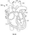
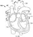
- FIG. 1is a highly schematic cutaway representation of a human heart showing a surgical delivery approach.
- FIG. 2Ais a highly schematic side view of one embodiment of a heart valve having a pair of sealing rings.
- FIG. 2Bis a highly schematic transverse cross-section through a sealing ring of FIG. 2A .
- FIGS. 2C-Dare highly schematic side views of the heart valve of FIG. 2A implanted into a native valve annulus with resected native valve leaflets.
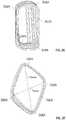
- FIG. 2Eis a front view of a rectangular coil of a sealing ring.
- FIG. 2Fis a front view of a diamond coil of a sealing ring.
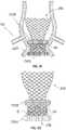
- FIG. 3Ais a highly schematic side view of one embodiment of a heart valve having bowed runners.
- FIG. 3Bis a developed view of the stent of the heart valve of FIG. 3A in the collapsed configuration.
- FIGS. 3C and 3Dare enlarged highly schematic partial plan views of a stent cell having a supra-annular runner in the collapsed configuration and bowed configuration, respectively.
- FIGS. 3E and 3Fare enlarged highly schematic partial plan views of a stent cell having a sub-annular runner in the collapsed configuration and bowed configuration, respectively.
- FIG. 3Gis a highly schematic side view of the heart valve of FIG. 3A implanted into a native valve annulus with resected native valve leaflets.
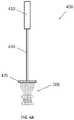
- FIG. 4Ais a highly schematic side view of a valve holder coupled to the prosthetic heart valve of FIG. 2A .
- FIGS. 4B-Dare highly schematic cutaway representations of a human heart showing a surgical method of delivering the prosthetic heart valve of FIG. 2A .
- FIG. 5is a highly schematic side view of the heart valve of FIG. 3A implanted into a native valve annulus with resected native valve leaflets after completion of the implantation procedure.
- FIG. 6Ais a developed view of a stent of another embodiment of a heart valve in the collapsed configuration.
- FIG. 6Bis a highly schematic side view of a heart valve incorporating the stent of FIG. 6A implanted into a native valve annulus with resected native valve leaflets after completion of the implantation procedure.
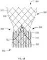
- FIG. 7is a highly schematic side view of a heart valve according to another embodiment implanted into a native valve annulus with resected native valve leaflets after completion of the implantation procedure.
- inflow endwhen used in connection with a prosthetic heart valve, refers to the end of the heart valve through which blood enters when the valve is functioning as intended.
- outlet flow endwhen used in connection with a prosthetic heart valve, refers to the end of the heart valve through which blood exits when the valve is functioning as intended.
- the terms “generally,” “substantially,” and “about”are intended to mean that slight deviations from absolute are included within the scope of the term so modified.
- Like numbersrefer to similar or identical elements throughout.
- the lengthwise or axial directionrefers to the direction along a longitudinal axis passing through the center of the stent or heart valve in the direction of blood flow.
- the circumferential directionrefers to the direction along the circumference of the prosthetic heart valve and about its longitudinal axis.
- the radial directionrefers a direction orthogonal to the longitudinal axis of the component (or otherwise to a direction having a component that is orthogonal to the longitudinal axis).
- FIG. 1is a highly schematic cutaway representation of human heart 100 .
- the human heartincludes two atria and two ventricles: right atrium 112 and left atrium 122 , and right ventricle 114 and left ventricle 124 .
- Heart 100further includes aorta 110 and aortic arch 120 .
- Disposed between left ventricle 124 and aorta 110is aortic valve 132 .
- Aortic valve 132is generally a three-leaflet valve that opens as a result of increased pressure in left ventricle 124 as it fills with blood.
- aortic valve 132opens and blood passes into aorta 110 . Blood flows through heart 100 in the direction shown by arrows “B”.
- a dashed arrow, labeled “DA,”indicates a direct aortic approach (or “surgical approach”) for implanting a prosthetic heart valve, in this case to replace aortic valve 132 .
- a prosthetic heart valvein this case to replace aortic valve 132 .
- an incisionsuch as an “L”-shaped aortotomy AT, is made in the aorta 110 .
- the prosthetic heart valveis generally coupled to a valve holder held by the surgeon, and the valve is manually inserted through the aortotomy AT and maneuvered to the site of implantation at aortic valve 132 .
- Other types of aortic incisionsmay also be appropriate, such as a transverse incision.
- Such methodsmay provide direct visualization of the implantation.
- the patientmay be placed on cardiopulmonary bypass.
- a prosthetic heart valvemay be sutured in place, using a sutureless prosthetic valve may provide for easier and faster placement, reducing the time the patient is kept on bypass.
- both sutureless valves and transcatheter valvesmay benefit from features that anchor the valve within the native valve annulus.
- hooks, barbs, or other structuresmay be coupled to the prosthetic heart valve to help maintain the position of the prosthetic heart valve in the native valve annulus, for example by hooking over a native heart valve leaflet.
- PV leakparavalvular leakage
- the prosthetic heart valvemay be provided with additional structures, some of which are described in greater detail below, that provide enhanced sealing between the prosthetic heart valve and the native valve annulus to minimize or prevent PV leak.
- Certain PV leak mitigation featuresmay provide an anchoring function in addition to the sealing function.
- the native aortic valve 132may have a diseased state which provides effective surfaces for anchoring.
- a patientmay have a native aortic valve 132 with thickened leaflets and/or calcific nodules on the leaflets. These diseased leaflets may provide a substrate suitable for anchoring a prosthetic heart valve.
- a prosthetic heart valve with hooks that hook over the diseased leafletmay provide suitable anchoring force to keep the prosthetic heart valve from migrating.
- the native leaflets of aortic valve 132may not provide a suitable substrate for anchoring.
- leaflets of native aortic valve 132may be partially or completely resected during the procedure of implanting the prosthetic heart valve. This may result in similar problems as are encountered in patients with aortic insufficiency in that it is more difficult to suitably anchor a prosthetic heart valve in a patient with partially or fully resected leaflets.
- an anchor feature that typically hooks over a native leafletmay be ineffective in anchoring when the native leaflets are partially or completely resected.
- FIG. 2Aillustrates a sutureless heart valve 200 according to one embodiment of the disclosure intended to reduce the likelihood and severity of PV leak between the heart valve and the native valve annulus and to provide effective anchoring in a variety of patient anatomies.
- Heart valve 200may have a stent 202 which extends between inflow end 230 and outflow end 232 , and a valve assembly 240 including a plurality of leaflets 208 and a cuff 206 .
- Stent 202may be wholly or partly formed of any biocompatible material, such as metals, synthetic polymers, or biopolymers capable of functioning as a stent.
- Suitable biopolymersinclude, but are not limited to, elastin, and mixtures or composites thereof.
- Suitable metalsinclude, but are not limited to, titanium, nickel, stainless steel, and alloys thereof, including nitinol.
- Other metals that have elastic and/or memory propertiesmay also be suitable, such as spring stainless steel, tradenamed alloys such as Elgiloy® and Hastelloy®, CoCrNi alloys (e.g., tradename Phynox), MP35N®, CoCrMo alloys, mixtures of such alloys or mixtures of metal and polymer fibers.
- Suitable synthetic polymers for use as a stentinclude, but are not limited to, thermoplastics, such as polyolefins, polyesters, polyamides, polysulfones, acrylics, polyacrylonitriles, polyetheretherketone (PEEK), and polyaramides.
- stent 202may be collapsible and expandable. This capability may allow prosthetic heart valve 200 to be delivered via a transcatheter approach while in a collapsed condition. Prosthetic heart valve 200 may also be delivered via a surgical approach without the use of sutures. Because stent 202 may tend to transition to the expanded condition in the absence of an applied restraining force, prosthetic heart valve 200 may be secured after implantation, at least in part, by radial force.
- stent 202need not be cylindrically shaped.
- stent 202may take the shape of an ellipse or other shapes, such as a general “D” shape with a substantially straight section and an arcuate section extending from one side of the straight section to the other.
- a “D” shapemay better conform to particular anatomies, such as the mitral valve, the tricuspid valve, or a diseased bicuspid valve.
- Other portions of the valvesuch as the sealing rings 250 A, 250 B, described in greater detail below, may take similar shapes including a general “D” shape, for example, depending on the stent 202 on which they are positioned.
- Valve assembly 240may be wholly or partly formed of any suitable biological material or polymer.
- biological materials suitable for valve assembly 240include, but are not limited to, porcine or bovine pericardial tissue.
- polymers suitable for valve assembly 240include, but are not limited to, polyurethane, silicone, PTFE, and polyester.
- portions of valve assembly 240including the cuff 206 and the suture used, may include an ultra-high molecular weight polyethylene.
- valve assembly 240typically includes one or more leaflets, other suitable valve assemblies without leaflets that work as one-way valves may be alternatively used.
- valve and stentmay take other forms.
- the valvecould be a bicuspid valve, i.e., a valve having two coapting leaflets, or other types of valves, including valves with a greater or lesser number of leaflets as well as non-leaflet valves.
- stent 202could have different shapes, such as a flared or conical annulus section, a more or less bulbous aortic section, a differently shaped transition section between the aortic section and the annulus section, or any other suitable shape, and may or may not be collapsible.
- Heart valve 200may include a pair of sealing elements, such as a sub-annular sealing ring 250 A at or near inflow end 230 of stent 202 , and a supra-annular sealing ring 250 B disposed closer to outflow end 232 than sub-annular sealing ring 250 A.
- the pair or sealing elementsmay help mitigate PV leak while simultaneously providing suitable anchoring force to anchor heart valve 200 in patients with various types of native anatomy.
- FIG. 2Billustrates an enlarged cross-sectional view of sealing ring 250 A taken along a cutting plane P transverse to the circumferential direction of sealing ring 250 A.
- Sealing ring 250 Bmay take a similar or identical form as sealing ring 250 A, with the main or only difference being the position of sealing ring 250 B with respect to stent 202 . As such, unless explicitly noted otherwise herein, sealing ring 250 B should be understood to be identical to sealing ring 250 A other than its position relative to stent 202 .
- sealing ring 250 Amay comprise tube 260 A with or without covering 270 A, with optional outer filler 280 A between covering 270 A and tube 260 A, and with optional inner filler 290 A inside tube 260 A.
- fillerrefers to outer filler 280 A and/or inner filler 290 A.
- Sealing ring 250 Amay include any combination of tube 260 A, covering 270 A, and filler. If outer filler 280 A is used, covering 270 A may be used to contain outer filler 280 A within sealing ring 250 A.
- FIGS. 2C-Dillustrate prosthetic heart valve 200 disposed within a native valve annulus VA from which the native valve leaflets have been resected.
- sealing ring 250 AWhen implanted within native valve annulus VA, sealing ring 250 A may be disposed, for example, below native valve annulus VA (i.e., in a sub-annular position). Sealing ring 250 B may be disposed, for example, above native valve annulus VA (i.e., in a supra-annular position). As shown in FIG. 2C , sealing ring 250 A is disposed such that it is in contact with the left ventricular outflow tract LVOT, while sealing ring 250 B is disposed between native valve annulus VA and coronary arteries CA.
- Such positioninghelps to provide a seal between prosthetic heart valve 200 and the native heart tissue. For example, as illustrated in FIG. 2D , despite gaps G between heart valve 200 and native valve annulus VA, sealing rings 250 A and 250 B help prevent retrograde blood flow around the outer circumference of valve 200 .
- sealing rings 250 A and 250 Balso provides robust anchoring on both sides of native valve annulus VA.
- sealing ring 250 Ahelps prevent heart valve 200 from migrating into aorta 110 while sealing ring 250 B helps prevent heart valve 200 from migrating into left ventricle 124 .
- the presence of both sub-annular sealing ring 250 A and supra-annular sealing ring 250 B to anchor prosthetic heart valve 200 on both sides of native valve annuls VAmay provide robust anchoring in a variety of patient populations, regardless of native valve anatomy.
- prosthetic heart valve 200may provide anchoring in patients that have their native aortic valve leaflets partially or fully resected, as well as in patients with conditions such as aortic insufficiency in which the native aortic valve leaflets are not resected but provide suboptimal substrate quality for anchoring. For example, in a patient that does not have the native valve leaflets resected, spacing the sub-annular sealing ring 250 A and supra-annular sealing ring 250 B between about 15 mm and about 20 mm apart may provide robust anchoring.
- spacingmay be between about 5 mm and about 15 mm, while in patients with fully resected leaflets may benefit from spacing of between about 2 mm and about 5 mm between sub-annular sealing ring 250 A and supra-annular sealing ring 250 B.
- the dimensions provided aboveare merely exemplary, and other dimensions may be suitable depending on the particular anatomy of a patient.
- sealing ring 250 Amay include elements such as tube 260 A, covering 270 A, and filler.
- Sealing ring 250 Bmay include similar or identical components.
- tube 260 Amay provide a structural support onto which covering 270 A may be attached and into which outer filler 280 A and/or inner filler 290 A may be inserted.
- Tube 260 Aalone may provide sealing and anchoring of prosthetic valve 200 , although such functions may be enhanced with the addition of covering 270 A and/or filler.
- Tube 260 A of sealing ring 250 Amay be formed of various materials, including any of those used to form stent 202 , and may have one or more of a variety of structures.
- the material of tube 260 Amay be individual strands braided into a generally tubular mesh structure, or may be an individual strand wound into a coil.
- the strands forming the braidmay have a particular relative orientation with respect to one another (e.g., a helical braid).
- Covering 270 Amay be formed of one or more materials having low permeability or no permeability to fluids, such as water and/or blood.
- covering 270 Amay be formed of tissue, including but not limited to pericardium or other sheet-like tissue obtained from animals or by tissue engineering.
- the covering 270 Amay be formed of a fabric-type material, such as a fabric formed of polytetrafluoroethylene (PTFE), polyethylene terephthalate (PET), or ultra-high molecular weight polyethylene (UHMWPE).
- the covering 270 Amay also be formed of synthetic or natural polymers, such as silicones, polyvinyl alcohol (PVA), or collagen sheets.
- the covering 270 Amay be formed of any one or any combination of the above-listed materials.
- the fillermay be formed of any of a variety of materials.
- the fillermay be composed of any of the materials used to form tube 260 A, such as a coil or mesh braid formed of Nitinol.
- the fillermay also be composed of any of the materials used to form covering 270 A, such as fabrics, tissues, and synthetic or natural polymers.
- the fillermay be composed of a water swellable material, such as natural sea sponge, swellable beads formed of, for example, PVA microspheres that expand upon contact with blood, or other materials that expand upon exposure to body conditions. Other materials that expand upon exposure to temperatures found in the body or to components of the blood may also be suitable for the filler.
- Another potential material for the filleris a highly compressible sponge, for example one made from alginate cross-linked at low temperatures. Such a highly compressible sponge may collapse to a large extent when shear forces are applied, while being able to return to its original shape upon removal of the forces.
- a single filler composed of a single material or a combination of materials described abovemay be used, or multiple fillers each composed of one or a combination of any of the above materials may be used.
- outer filler 280 Amay be formed of a first material while inner filler 290 A may be formed of a second material.
- a homogenous mixture of different materialsmay be used for outer filler 280 A and/or inner filler 290 A.
- fillers of different materialsmay be positioned in different sections of sealing ring 250 A, or fillers may be provided as layers of different materials.
- prosthetic heart valve 200may include sealing ring 250 A that includes tube 260 A formed of a braided mesh of a shape-memory material, of a super-elastic material, of a bio-compatible polymer, or of another material, including those that are capable of being collapsed and expanded into a desired shape.
- tube 260 Amay take the shape of a hollow torus wrapped around a portion of stent 202 . It should be understood that tube 260 A need not meet the precise mathematical definition of a torus or other toroid.
- Tube 260 Amay comprise a braided metal fabric that is both resilient and capable of heat treatment to substantially set a desired shape, such as Nitinol, or any other metal described above that is suitable for forming stent 202 .
- a desired shapesuch as Nitinol, or any other metal described above that is suitable for forming stent 202 .
- other materialssuch as braided polymers, including polypropylene, may be used for the braided mesh version of tube 260 A.
- the strand diameter, number of strands per area or strand density, and pitchmay be altered to achieve the desired properties for tube 260 A.
- sealing ring 250 Acomprises only braided mesh, the braided tube 260 A may help in reducing PV leak, for example by creating a seal as blood clots form in the braid.
- PV leakmay be further mitigated to the extent tissue in-growth occurs on sealing ring 250 A, such as by endothelialization and/or epithelialization.
- tissue in-growthoccurs on sealing ring 250 A, such as by endothelialization and/or epithelialization.
- Such sealing by clotting and/or thrombus formationmay take up to an hour or more to form, with tissue in-growth occurring over a longer time.
- faster sealingmay be desirable.
- rapid sealingmay provide a physician with immediate or near immediate feedback that PV leak is not occurring at unacceptable levels.
- Covering 270 A and/or fillermay be used in combination with braided tube 260 A (or a coiled tube 260 A as described below) to accelerate sealing and enhance tissue in-growth.
- One of the advantages of using braided Nitinol for tube 260 Ais that the structure relatively easily undergoes a transition into different shapes. This may provide benefits for delivery via a transcatheter approach or a surgical approach. For example, it may be easily collapsible for delivery, easily expandable upon implantation, and may change shape as appropriate to fill in gaps G in native annulus VA. However, as noted above, it may be desirable to add a covering 270 A and/or filler if tube 260 A is formed of braided mesh. The addition of such material may change the way the braided mesh changes shapes. In particular, if the braid is covered tightly with a covering 270 A, the braid may not expand as freely as it would without such a covering.
- One possible solution to this challengeis choosing a flexible material for covering 270 A, as well as loosely attaching covering 270 A to tube 260 A.
- suturesmay be used to form tacking stitches or expandable stitches to couple covering 270 A to tube 260 A.
- Another possible solutionis to use a different structure for tube 260 A.
- the ability of tube 260 A to change shapemay be less important than when implantation is accomplished using a transcatheter approach.
- tube 260 Amay be formed of a coiled material, such as coiled Nitinol (or any other material suitable for use in forming stent 202 ).
- tube 260 Amay be formed of a single strand or wire of material, or single stands or wires of material attached end-to-end, coiled into a desired shape.
- tube 260 Amay be formed of a strand or wire of Nitinol coiled into a circular shape, a rectangular shape, or a diamond shape.
- the strands of material forming the coilmay have various cross-sectional shapes, such as round, flat (e.g., a ribbon), rectangular, or others, all of which are referred to hereafter as “wires.” Still further, one or more wires may be wound into a coil having parallel windings, multiple wires may be wound together in different directions (e.g., to form a braid), or two or more wires may be wound together in the same direction (e.g., two or more wires wound as a double helix). In addition, the coil need not be a closed coil, but may be an open coil having, for example, a “U” or “C” shape.
- tube 260 Amay have different qualities when formed from a coil compared to those exhibited by a braided mesh. For example, a tube 260 A formed from a coil may collapse to a smaller profile than a similar tube formed of a braided mesh.
- sealing ring 250 Ais formed solely of a tube 260 A comprising a coil, sealing via clotting may be slower than with the braided mesh version, or may never occur at all. But when covering 270 A and/or filler is included with a tube 260 A formed of a coil, sealing ring 250 A may seal against PV leak rapidly.
- a covering 270 A and/or fillermay similarly be used in conjunction with a braided mesh version of tube 260 A, in which case the sealing quality may be similar to that achieved when a covering 270 A and/or filler is used with a coiled version of tube 260 A.
- tube 260 Awhen tube 260 A is formed of a coil, the coil may take different general shapes, such as that of a circle (not illustrated), of a rectangle ( FIG. 2E ), or of a diamond ( FIG. 2F ).
- the coils shown in FIGS. 2E-Fare viewed along the same cutting plane P shown in FIG. 2B . As such, multiple turns or iterations of each coil shape are visible in FIGS. 2E-F . Stated more precisely, the shape of each individual turn of the coils shown is a rectangle ( FIG. 2E ) or a diamond ( FIG. 2F ).
- the shape of the coilmay provide certain advantages, depending on the techniques used to implant the prosthetic heart valve.
- Prosthetic heart valve 200may alternatively be delivered via a transcatheter approach in which the prosthetic heart valve is collapsed, loaded into a delivery catheter, and delivered to the site of implantation.
- the shapes of the coil forming tube 260 A described abovemay be advantageous for a transcatheter delivery technique because, for example, the corners 264 A of rectangular coil 262 A and the peaks 268 A of diamond coil 266 A facilitate the collapse of the respective coils during loading, delivery, and/or resheathing of valve 200 .
- rectangular coil 262 Ais shown in FIG. 2E (and diamond coil 266 A in FIG. 2F ) not in the form of tube 260 A, but rather a segment thereof.
- rectangular coil 262 A or diamond coil 266 Awould extend along a circumferential path around inflow end 230 of valve 200 , forming tube 260 A.
- the term “tube”does not solely refer to an elongated cylindrical structure, as the rectangular coil 262 A and diamond coil 266 A extending circumferentially around stent 202 is still considered herein as a tube 260 A.
- the tube 260 Aneed not be a toroid at all.
- tube 260 A of sealing ring 250 Amay undulate such that points on its proximal (or distal) surface do not lie in the same plane as other points on its proximal (or distal) surface.
- sealing ring 250 Amay have an undulating quality as well.
- Varying the geometric of the shape of the coilmay provide for different effects in terms of profile and sealing.
- the lengths of the major axis X MAJOR and minor axis X MINORmay be, respectively, approximately 3 mm and approximately 2 mm, approximately 4 mm and approximately 2 mm, or approximately 4 mm and approximately 3 mm.
- These lengths of the major and minor axesshould be understood to be examples, and not requirements.
- the examples given abovemay be useful for achieving a bulge in sealing ring 250 A of between about 2 mm and about 5 mm from the outer circumference of the stent 202 , which may be particularly effective at reducing PV leak.
- the bulge formedwill be approximately the length of minor axis X MINOR .
- coil 268 Amay be attached at other locations so that the bulge is any size between X MINOR and X MAJOR .
- wires having cross-sections other than circular, including flat and/or rectangular,may be used to form coil tube 260 A. While the thickness of the wire forming the coil of tube 260 A may vary, one exemplary range of thicknesses is between about 0.05 mm and about 0.175 mm. Where the wire has a circular cross-section, the thickness of the wire will be equal to its diameter.
- the thickness of the wirewill be equal to its width. It should be noted that the above dimensions provided in relation to components of tube 260 A, as well as any other dimensions provided herein, are for illustrative purposes. Different dimensions may be used without departing from the scope of this disclosure.
- tube 260 Amay be modified and optimized to achieve a better seal against PV leak, including, for example, the coil or braid density, shape, and stiffness.
- the ratio of the thickness of the wire to the spacing between adjacent iterative windings of the coili.e., pitch
- a relatively large ratio of wire thickness to pitchmay lead to kinking or tenting (i.e., a deviation from a smooth circumference) in the tube 260 A, which may reduce the effectiveness of sealing against PV leak.
- sealing rings 250 A and 250 Bare described above as being substantially similar or identical, certain differences may enhance the performance of prosthetic heart valve 200 .
- sealing rings incorporating a tube formed from a coiled wirethe greater the thickness of the wire, the greater the radial force exerted by the tube will be.
- sealing rings 250 A and 250 Binclude tubes formed from a coiled wire
- the wire forming the coil of the tubemay be thicker for supra-annular sealing ring 250 B than for sub-annular sealing ring 250 A.
- the wire forming the coiled tube 260 A of sub-annular sealing ring 250 Amay have a thickness between about 0.05 mm and about 0.175 mm
- the thickness of the wire forming the coiled tube of supra-annular sealing ring 250 Bmay be between about 1.5 and about 2 times greater, or between about 0.075 mm and about 0.350 mm.
- coiled tubemay be manipulated to alter the radial force, including cross-sectional dimensions of the wire forming the coiled tube, the pitch and/or spacing of the coil, the shape of each turn of the coil, and material choice and/or processing of the material of the wire forming the coil. Still further, due to the positioning of supra-annular sealing ring 250 B near the coronary arteries CA, it may be important to size the supra-annular sealing ring to avoid occluding the coronary arteries CA.
- FIG. 3Aillustrates a heart valve 300 according to another embodiment intended to provide robust anchoring on each side of a native heart valve, such as native aortic valve 132 , while also reducing the occurrence of PV leak.
- Heart valve 300extends between inflow end 302 and outflow end 304 , and may generally include stent 306 and valve assembly 308 having a plurality of leaflets 310 and cuff 312 .
- Heart valve 300may be formed of any of the materials and in any of the configurations for forming heart valve 200 as described above.
- Stent 306may include a plurality of struts 320 .
- Struts 320may come together to form cells 322 connected to one another in one or more annular rows around the stent.
- Connected to struts 320are a plurality of sub-annular runners 330 and supra-annular runners 350 , which are additional struts that bow or bulge out radially when stent 306 is in a relaxed condition, as is described in greater detail with reference to FIGS. 3B and 3C .
- stent 306is shown in FIG. 3B in a collapsed and flattened condition (i.e., as if the stent had been cut longitudinally and flattened to a single layer thickness). It should be understood that although stent 306 may be collapsible and expandable, the method of delivery of prosthetic heart valve 300 is not limited to transcatheter delivery, but may alternatively be delivered via a surgical approach while in a partially or fully expanded condition, as described in greater detail in connection with FIGS. 4A-D . For the sake of clarity, valve assembly 308 is not shown in FIG. 3B .
- stent 306includes four annular rows of cells 370 a - d extending from inflow end 302 to outflow end 304 . In the collapsed configuration of stent 306 , each of cells 322 is also collapsed. Stent 306 extends from inflow or annulus end 302 of heart valve 300 to outflow or aortic end 304 , and includes annulus section 340 adjacent inflow end 302 , aortic section 342 adjacent outflow end 304 , and transition section 341 between annulus section 340 and aortic section 342 . Commissure attachment features 345 may be positioned entirely within annulus section 340 or at the juncture of annulus section 340 and transition section 341 .
- One or more cells 322 in the second annular row of cells 370 bmay include supra-annular runners 350 nested therein.
- An enlarged partial plan view of cell 322 including a supra-annular runner 350is shown in FIG. 3C .
- Four struts 320 a , 320 b , 320 c , 320 dmay join to form cell 322 , each strut being attached to two adjacent struts.
- cell 322In the collapsed configuration of stent 306 , cell 322 may be stadium-shaped as shown.
- cell 322In the expanded configuration of stent 306 , cell 322 may shorten in the length direction of stent 306 between inflow end 302 and outflow end 304 , and struts 320 may generally form a diamond shape ( FIG. 3D ).
- Supra-annular runners 350may extend across cell 322 from first attachment end 335 a where struts 320 a and 320 c meet to second attachment end 335 b where struts 320 b and 320 d meet, and may be affixed to stent 306 by welding, adhesive, or any other suitable technique known in the art. Rather than being separately formed and affixed to stent 306 at attachment ends 335 a and 335 b , runners 350 may be integrally formed with stent 306 , such as by laser cutting both stent 306 and runners 350 from the same tube. Runners 350 may be formed of a shape memory material such as those described above for forming stent 202 of FIG. 2A , and may have a substantially linear configuration in the collapsed configuration of heart valve 300 ( FIG. 3C ) and a curved or bowed configuration in the expanded configuration of heart valve 300 ( FIG. 3D ).
- runner 350may bisect cell 322 into first portion 360 a and second portion 360 b .
- runner 350bows or deflects outwardly of the surface defined by struts 320 a , 320 b , 320 c , and 320 d .
- Stent 306may also be heat set such that struts 320 and runner 350 return to a predetermined shape in the fully expanded or relaxed configuration (e.g., when no external forces are applied thereto).
- the cuffis substantially tubular when runners 350 are not bowed outwardly.
- runners 350bow outwardly on the expansion of heart valve 300 , they form protuberances in cuff 312 to help anchor and seal heart valve 300 within the native valve annulus VA.
- the runners 350may bow outwardly between about 3 mm and about 5 mm, with the length of runners 350 being between about 8 mm and about 10 mm.
- these dimensionsare merely exemplary and other dimensions may be suitable.
- FIG. 3Eshows an enlarged partial plan view of the inflow end 302 of stent 306 in the collapsed condition.
- each of cells 322is also collapsed.
- Each cell 322 in the first annular row of cells 370 a positioned nearest the inflow end 302 of stent 306may include four struts that join to form cell 322 , with two of the four struts 320 e and 320 f shown in FIG. 3E .
- Runners 330may be positioned in the space between adjacent cells 322 at the inflow end 302 of stent 306 .
- each runner 330is positioned in the space between strut 322 f of one cell 322 in the first row 370 a and strut 322 e of an adjacent cell 322 in the first row. More particularly, each runner 330 has a first end joined to stent 306 at the juncture of strut 322 e of one cell 322 and strut 322 e of an adjacent cell 322 , and a second free end extending toward inflow end 302 of the stent. As with supra-annular runners 350 , sub-annular runners 330 may be affixed to stent 306 or integrally formed with the stent.
- Runners 330may also be formed of a shape memory material such as those described above for forming stent 202 of FIG. 2A , and may have a substantially linear configuration in the collapsed configuration of heart valve 300 ( FIG. 3E ) and a curved or bowed configuration in the expanded configuration of heart valve 300 ( FIG. 3F ).
- sub-annular runners 330are attached to stent 302 at only one end. While supra-annular runners 350 may bow outwardly by virtue of a cell 322 shortening, the same is not true of sub-annular runners 330 .
- sub-annular runners 330may be shape-set, such as by heat setting, so that in the absence of externally applied forces, runners 330 deflect or bow outwardly of the surface defined by struts 320 e and 320 f .
- cuff 312FIG. 3A
- the cuffis substantially tubular when runners 330 are not bowed outwardly.
- runners 330When runners 330 bow outwardly on the expansion of heart valve 300 , they form protuberances in cuff 312 to help anchor and seal heart valve 300 within the native valve annulus VA.
- runners 330may extend between about 5 mm and about 10 mm radially outward from stent 302 in the absence of externally applied force.
- these dimensionsare merely exemplary and other dimensions may be suitable depending on the exact location
- FIG. 3Gillustrates prosthetic heart valve 300 disposed within a native valve annulus VA from which the native valve leaflets have been resected.
- runners 330bow outwardly, for example as defined by their pre-set shape, and may be disposed below native valve annulus VA (i.e., in a sub-annular position).
- Runners 350also bow outwardly and may be disposed, for example, above native valve annulus VA (i.e., in a supra-annular position).
- runners 330are disposed such that they are in contact with the left ventricular outflow tract LVOT, while runners 350 are disposed between native valve annulus VA and coronary arteries CA.
- prosthetic heart valve 300may provide anchoring in patients that have their native aortic valve leaflets partially or fully resected, as well as in patients with conditions such as aortic insufficiency in which the native aortic valve leaflets are not resected but provide suboptimal substrate quality for anchoring.
- FIGS. 4A-Dillustrate an exemplary sutureless method of replacing native aortic valve 132 with a prosthetic heart valve according to the present disclosure.
- the method illustrated and describedis with reference to prosthetic heart valve 200 , it should be understood that the method is equally applicable to the implantation of prosthetic heart valve 300 , or other prosthetic heart valves having sub-annular and supra-annular features for anchoring the prosthetic heart valve and mitigating PV leak.
- prosthetic heart valve 200is provided and is coupled to valve holder 400 .
- Valve holder 400may generally include a handle 410 for gripping by the surgeon, a base 420 for coupling to prosthetic heart valve 200 , and a shaft 430 connecting the handle to the base.
- Valve holder 400is merely one example of a valve holder, and other designs may be suitable for use with the prosthetic heart valves disclosed herein.
- valve holder 400may alternatively include a base that attaches to prosthetic heart valve 200 by means other than sutures, such as by corresponding releasable mating features on prosthetic heart valve 200 and base 420 .
- Valve holder 400may be provided with still other features, such as a base 420 that radially shrinks during delivery to provide the surgeon a better field of view of the implantation procedure.
- the patientBefore or after prosthetic heart valve 200 is coupled to valve holder 400 , the patient may be put on cardiopulmonary bypass and the beating of heart 100 may be ceased. The time during which the patient remains on bypass is preferably minimized to the extent possible. As shown in FIG. 4B , once the patient is on bypass, an incision may be made in aorta 110 to provide direct access to aortic valve 132 . For example, the surgeon may make an “L” shaped aortotomy AT in aorta 110 . It should be understood that the heart 100 and location of the aortotomy AT in aorta 110 is not to scale.
- the incision in aorta 110would preferably be closer to aortic valve 132 than shown to provide the least practical distance between the incision and the aortic valve.
- the surgeonmay partially or fully resect the native leaflets of aortic valve 132 , if the leaflets have not been resected in a prior procedure, such as a prior prosthetic valve implantation.
- the surgeonmay grasp handle 410 of valve holder 400 and advance prosthetic heart valve 200 into aorta 110 and toward the annulus of aortic valve 132 .
- the incision in aorta 110may provide full or nearly full visualization of the procedure to the surgeon.
- the surgeonmay advance prosthetic heart valve 200 until native valve annulus VA is captured between sealing ring 250 A and sealing ring 250 B, as shown in FIG. 4C (also shown in FIG. 2C ).
- the surgeonmay disconnect prosthetic heart valve 200 from the base 420 of valve holder 400 , for example by cutting one or more sutures connecting the prosthetic heart valve to the base.
- FIG. 4Dthe surgeon may remove valve holder 400 from the patient's heart 100 , suture aortotomy AT closed, take the patient off bypass, and restart the heart.
- the implantation procedurefrom the creation of aortotomy AT to the suturing of the aortotomy closed, is relatively simple and fast.
- This sutureless approachprovides the surgeon full visualization of the procedure, and the surgeon is able to secure the prosthetic heart valve in native valve annulus VA without the need for suturing the prosthetic heart valve to the anatomy or any other additional procedures.
- sub-annular sealing ring 250 A and supra-annular sealing ring 250 B in prosthetic heart valve 200helps ensure that there is no paravalvular leakage once the heart starts beating again, and that the prosthetic heart valve 200 remains robustly anchored in native valve annulus VA, even if the native valve leaflets have been resected or if the patient has native valve leaflets that do not provide a suitable substrate for anchoring.
- the identical or nearly identical procedurewould be used for prosthetic heart valve 300 , with the exception that sub-annular runners 330 and supra-annular runners 350 would provide the anchoring and sealing between native valve annulus VA and prosthetic heart valve 300 .
- prosthetic heart valves 200 and 300are collapsible and expandable, a transcatheter delivery approach may also be employed.
- a transcatheter approachmay provide, for example, a less invasive procedure and eliminate the need for a patient to be put on bypass.
- a transcatheter approachrequires imaging technology to determine where the prosthetic heart valve is in relation to the patient's anatomy.
- the sutureless approachmay provide for full visualization to the surgeon through the incision.
- prosthetic heart valves 200 and 300may be implanted using a full surgical approach in which the prosthetic heart valve is sutured in place in the native valve annulus. As noted previously, such procedure is much more time-consuming and creates a greater risk of infection
- FIGS. 4B-Dshow prosthetic heart valve 300 positioned in native valve annulus VA of a patient, after aortotomy AT has been closed with one or more sutures S.
- FIG. 5better illustrates the relative positioning between the incision made in aorta 110 and the implanted prosthetic heart valve 300 .
- a portion of prosthetic heart valve 300may abut or otherwise contact the closed aortotomy AT. This position may be undesirable because contact between prosthetic heart valve 300 and closed aortotomy AT may prevent healing of the incision site, or may cause injury such as interfering with sutures S or reopening of the incision.
- stent 306may be formed without aortic section 342 and some or all of transition section 341 .
- FIG. 6Aillustrates stent 306 ′ for use with a prosthetic heart valve 300 ′ according to another embodiment, the stent being in a collapsed and flattened configuration.
- prosthetic heart valves 300 and 300 ′may be identical in all respects, with the exception that stent 306 ′ has a shorter length than stent 306 .
- stent 306 ′includes first and second rows of cells 370 a - b .
- prosthetic heart valve 300 ′may include a valve assembly 308 ′ identical to valve assembly 308 and coupled to commissure attachment features 345 ′.
- Prosthetic heart valve 300 ′may also include a cuff 312 ′ identical to cuff 312 of prosthetic heart valve 300 .
- Stent 306 ′is configured so that it has an annulus section 340 ′, but no aortic section (flared or otherwise).
- stent 306 ′includes sub-annular runners 330 ′ and supra-annular runners 350 ′ that are similar or identical to sub-annular runners 330 and supra-annular runners 350 of stent 306 .
- FIG. 6Billustrates prosthetic heart valve 300 ′ implanted in native valve annulus VA, with runners 330 ′ and runners 350 ′ anchoring the prosthetic heart valve on each side of the native valve annulus.
- the axial length of stent 306 ′is shorter than that of stent 306 , and may reduce or eliminate the likelihood that any part of prosthetic heart valve 300 ′ rubs, contacts, or otherwise interferes with closed aortotomy AT after implantation.
- a flared aortic sectionsuch as aortic section 342 of stent 306 , may provide some amount of anchoring and resistance to migration of the stent into left ventricle 124 , and may further facilitate the axial centering of the stent with respect to the axial center of native valve annulus VA.
- the robust anchoring provided by runners 330 ′ and 350 ′ about native valve annulus VAmay make it unnecessary to have a flared aortic section.
- Prosthetic heart valve 300 ′may be delivered and implanted in the same manner as described above with respect to prosthetic heart valve 200 .
- FIG. 7shows prosthetic heart valve 200 ′ implanted in native valve annulus VA, with sub-annular sealing ring 250 A′ and supra-annular sealing ring 250 B′ capturing and anchoring the prosthetic heart valve to the native valve annulus.
- Prosthetic heart valve 200 ′may be identical to prosthetic heart valve 200 in all respects, with the exception that stent 202 ′ includes only an annulus section so that it is shorter than stent 202 , reducing the likelihood of prosthetic heart valve 200 ′ irritating or interfering with closed aortotomy AT.
- Prosthetic heart valve 200 ′may be delivered and implanted in the same manner as described above with respect to prosthetic heart valve 200 .
- a prosthetic heart valvemay include either the long stent of prosthetic heart valves 200 and 300 , or the short stent of prosthetic heart valves 200 ′ and 300 ′. Regardless of the type of stent employed, the prosthetic heart valve may have a supra-annular sealing and anchoring feature in the form of either the sealing ring 250 B of prosthetic heart valve 200 , or the runner 350 of prosthetic heart valve 300 . Similarly, the prosthetic heart valve may also include a sub-annular sealing and anchoring feature in the form of either the sealing ring 250 A of prosthetic heart valve 200 , or the runner 330 of prosthetic heart valve 300 .
- a prosthetic heart valvemay include a combination of a sealing ring 250 A and runners 350 or a combination of a sealing ring 250 B and runners 330 , and these combinations may be present on either a long stent or a short stent as described herein.
- a prosthetic heart valve for replacing a native valveincludes a stent extending between an inflow end and an outflow end, the stent including an annulus section adjacent the inflow end, a plurality of first struts connected to the stent and configured to extend radially outwardly from the stent when in a relaxed condition, and a plurality of second struts connected to the stent and configured to extend radially outwardly from the stent when in the relaxed condition, the plurality of first struts being spaced from the plurality of second struts in a longitudinal direction of the stent; and a valve assembly disposed within the stent; and/or
- valve assemblymay include a cuff disposed around an exterior of the annulus section and covering the plurality of first struts and the plurality of second struts; and/or
- the prosthetic heart valvemay include a plurality of third struts forming cells, each of the first struts being nested within one of the cells when the stent is in a collapsed condition; and/or
- the prosthetic heart valvemay include a plurality of third struts forming cells, each of the second struts having a first end connected to at least one of the third struts; and/or
- each of the second strutsmay have a free end
- the stentmay be collapsible and expandable; and/or
- the plurality of first strutsmay be positioned closer to the outflow end of the stent than the plurality of second struts.
- a prosthetic heart valveincludes a stent extending from an inflow end to an outflow end; a first sealing ring coupled to the stent adjacent the inflow end of the stent, the first sealing ring comprising a first tube extending circumferentially around the stent; a second sealing ring coupled the stent, the second sealing ring comprising a second tube extending circumferentially around the stent, the second sealing ring being spaced from the first sealing ring in a longitudinal direction of the stent; and a valve assembly disposed within the stent; and/or
- the first tubemay include a first wire coiled into a first repeating shape and the second tube may include a second wire coiled into a second repeating shape;
- the first and second repeating shapesmay be selected from the group consisting of a rectangular shape and a diamond shape; and/or
- the first wiremay have a first thickness and the second wire may have a second thickness less than the first thickness;
- one of the first and second tubesmay be formed of a braided mesh
- the stentmay be collapsible and expandable.
- a further embodiment of the disclosureprovides a method of implanting a prosthetic heart valve in a patient, the prosthetic heart valve including a first valve anchoring feature spaced apart from a second valve anchoring feature.
- the methodincludes inserting the prosthetic heart valve into the patient's cardiovascular system while coupled to a valve holder; advancing the prosthetic heart valve to a position adjacent a native valve annulus in the patient so that the first valve anchoring feature is disposed on a first side of the native valve annulus and the second valve anchoring feature is disposed on a second side of the native valve annulus opposite the first side; releasing the prosthetic heart valve from the valve holder; and removing the valve holder from the patient; and/or
- the methodmay further include making an incision in the aorta of the patient prior to inserting the prosthetic heart valve into the patient's cardiovascular system; and closing the incision after removing the valve holder from the patient, wherein, after the closing step, the prosthetic heart valve does not contact the closed incision; and/or
- the prosthetic heart valvemay have an expanded condition and a collapsed condition
- the inserting stepmay include inserting the prosthetic heart valve into the patient's cardiovascular system in the expanded condition
- the first valve anchoring featuremay be selected from the group consisting of a sealing ring attached to a stent of the prosthetic heart valve and configured to extend radially outward from the stent and a strut attached to the stent and configured to extend radially outward from the stent; and/or
- the second valve anchoring featuremay be selected from the group consisting of a sealing ring attached to the stent and configured to extend radially outward from the stent and a strut attached to the stent and configured to extend radially outward from the stent.
Landscapes
- Health & Medical Sciences (AREA)
- Engineering & Computer Science (AREA)
- Biomedical Technology (AREA)
- Cardiology (AREA)
- Oral & Maxillofacial Surgery (AREA)
- Transplantation (AREA)
- Heart & Thoracic Surgery (AREA)
- Vascular Medicine (AREA)
- Life Sciences & Earth Sciences (AREA)
- Animal Behavior & Ethology (AREA)
- General Health & Medical Sciences (AREA)
- Public Health (AREA)
- Veterinary Medicine (AREA)
- Prostheses (AREA)
Abstract
Description
Claims (9)
Priority Applications (1)
| Application Number | Priority Date | Filing Date | Title |
|---|---|---|---|
| US15/743,131US10639149B2 (en) | 2015-07-16 | 2016-06-30 | Sutureless prosthetic heart valve |
Applications Claiming Priority (3)
| Application Number | Priority Date | Filing Date | Title |
|---|---|---|---|
| US201562193184P | 2015-07-16 | 2015-07-16 | |
| US15/743,131US10639149B2 (en) | 2015-07-16 | 2016-06-30 | Sutureless prosthetic heart valve |
| PCT/US2016/040392WO2017011199A1 (en) | 2015-07-16 | 2016-06-30 | Sutureless prosthetic heart valve |
Publications (2)
| Publication Number | Publication Date |
|---|---|
| US20190099265A1 US20190099265A1 (en) | 2019-04-04 |
| US10639149B2true US10639149B2 (en) | 2020-05-05 |
Family
ID=56373204
Family Applications (1)
| Application Number | Title | Priority Date | Filing Date |
|---|---|---|---|
| US15/743,131ActiveUS10639149B2 (en) | 2015-07-16 | 2016-06-30 | Sutureless prosthetic heart valve |
Country Status (4)
| Country | Link |
|---|---|
| US (1) | US10639149B2 (en) |
| EP (1) | EP3322381B1 (en) |
| JP (1) | JP6600068B2 (en) |
| WO (1) | WO2017011199A1 (en) |
Families Citing this family (54)
| Publication number | Priority date | Publication date | Assignee | Title |
|---|---|---|---|---|
| US8579964B2 (en) | 2010-05-05 | 2013-11-12 | Neovasc Inc. | Transcatheter mitral valve prosthesis |
| US9308087B2 (en) | 2011-04-28 | 2016-04-12 | Neovasc Tiara Inc. | Sequentially deployed transcatheter mitral valve prosthesis |
| US9554897B2 (en) | 2011-04-28 | 2017-01-31 | Neovasc Tiara Inc. | Methods and apparatus for engaging a valve prosthesis with tissue |
| US9345573B2 (en) | 2012-05-30 | 2016-05-24 | Neovasc Tiara Inc. | Methods and apparatus for loading a prosthesis onto a delivery system |
| US9572665B2 (en) | 2013-04-04 | 2017-02-21 | Neovasc Tiara Inc. | Methods and apparatus for delivering a prosthetic valve to a beating heart |
| WO2015126711A1 (en)* | 2014-02-18 | 2015-08-27 | St. Jude Medical, Cardiology Division, Inc. | Bowed runners and corresponding valve assemblies for paravalvular leak protection |
| CA3007660A1 (en) | 2015-12-15 | 2017-06-22 | Neovasc Tiara Inc. | Transseptal delivery system |
| US10433952B2 (en) | 2016-01-29 | 2019-10-08 | Neovasc Tiara Inc. | Prosthetic valve for avoiding obstruction of outflow |
| CA3042588A1 (en) | 2016-11-21 | 2018-05-24 | Neovasc Tiara Inc. | Methods and systems for rapid retraction of a transcatheter heart valve delivery system |
| US10813749B2 (en)* | 2016-12-20 | 2020-10-27 | Edwards Lifesciences Corporation | Docking device made with 3D woven fabric |
| US10653523B2 (en) | 2017-01-19 | 2020-05-19 | 4C Medical Technologies, Inc. | Systems, methods and devices for delivery systems, methods and devices for implanting prosthetic heart valves |
| US10561495B2 (en) | 2017-01-24 | 2020-02-18 | 4C Medical Technologies, Inc. | Systems, methods and devices for two-step delivery and implantation of prosthetic heart valve |
| US12029647B2 (en) | 2017-03-07 | 2024-07-09 | 4C Medical Technologies, Inc. | Systems, methods and devices for prosthetic heart valve with single valve leaflet |
| US12036113B2 (en) | 2017-06-14 | 2024-07-16 | 4C Medical Technologies, Inc. | Delivery of heart chamber prosthetic valve implant |
| CA3073834A1 (en) | 2017-08-25 | 2019-02-28 | Neovasc Tiara Inc. | Sequentially deployed transcatheter mitral valve prosthesis |
| US11147667B2 (en)* | 2017-09-08 | 2021-10-19 | Edwards Lifesciences Corporation | Sealing member for prosthetic heart valve |
| US10874513B2 (en)* | 2018-02-12 | 2020-12-29 | 4C Medical Technologies, Inc. | Expandable frames and paravalvular leak mitigation systems for implantable prosthetic heart valve devices |
| WO2019195860A2 (en) | 2018-04-04 | 2019-10-10 | Vdyne, Llc | Devices and methods for anchoring transcatheter heart valve |
| US11857441B2 (en) | 2018-09-04 | 2024-01-02 | 4C Medical Technologies, Inc. | Stent loading device |
| US11278437B2 (en) | 2018-12-08 | 2022-03-22 | Vdyne, Inc. | Compression capable annular frames for side delivery of transcatheter heart valve replacement |
| US10595994B1 (en) | 2018-09-20 | 2020-03-24 | Vdyne, Llc | Side-delivered transcatheter heart valve replacement |
| US11071627B2 (en) | 2018-10-18 | 2021-07-27 | Vdyne, Inc. | Orthogonally delivered transcatheter heart valve frame for valve in valve prosthesis |
| US10321995B1 (en) | 2018-09-20 | 2019-06-18 | Vdyne, Llc | Orthogonally delivered transcatheter heart valve replacement |
| US11344413B2 (en) | 2018-09-20 | 2022-05-31 | Vdyne, Inc. | Transcatheter deliverable prosthetic heart valves and methods of delivery |
| US12186187B2 (en) | 2018-09-20 | 2025-01-07 | Vdyne, Inc. | Transcatheter deliverable prosthetic heart valves and methods of delivery |
| US11109969B2 (en) | 2018-10-22 | 2021-09-07 | Vdyne, Inc. | Guidewire delivery of transcatheter heart valve |
| CN113271890B (en) | 2018-11-08 | 2024-08-30 | 内奥瓦斯克迪亚拉公司 | Ventricular deployment of transcatheter mitral valve prosthesis |
| US11253359B2 (en) | 2018-12-20 | 2022-02-22 | Vdyne, Inc. | Proximal tab for side-delivered transcatheter heart valves and methods of delivery |
| US10653522B1 (en) | 2018-12-20 | 2020-05-19 | Vdyne, Inc. | Proximal tab for side-delivered transcatheter heart valve prosthesis |
| WO2020146842A1 (en) | 2019-01-10 | 2020-07-16 | Vdyne, Llc | Anchor hook for side-delivery transcatheter heart valve prosthesis |
| US11185409B2 (en) | 2019-01-26 | 2021-11-30 | Vdyne, Inc. | Collapsible inner flow control component for side-delivered transcatheter heart valve prosthesis |
| US11273032B2 (en) | 2019-01-26 | 2022-03-15 | Vdyne, Inc. | Collapsible inner flow control component for side-deliverable transcatheter heart valve prosthesis |
| WO2020181154A2 (en) | 2019-03-05 | 2020-09-10 | Vdyne, Inc. | Tricuspid regurgitation control devices for orthogonal transcatheter heart valve prosthesis |
| CA3132873A1 (en) | 2019-03-08 | 2020-09-17 | Neovasc Tiara Inc. | Retrievable prosthesis delivery system |
| US11076956B2 (en) | 2019-03-14 | 2021-08-03 | Vdyne, Inc. | Proximal, distal, and anterior anchoring tabs for side-delivered transcatheter mitral valve prosthesis |
| US10758346B1 (en) | 2019-03-14 | 2020-09-01 | Vdyne, Inc. | A2 clip for side-delivered transcatheter mitral valve prosthesis |
| US10631983B1 (en) | 2019-03-14 | 2020-04-28 | Vdyne, Inc. | Distal subannular anchoring tab for side-delivered transcatheter valve prosthesis |
| US11173027B2 (en) | 2019-03-14 | 2021-11-16 | Vdyne, Inc. | Side-deliverable transcatheter prosthetic valves and methods for delivering and anchoring the same |
| CA3135753C (en) | 2019-04-01 | 2023-10-24 | Neovasc Tiara Inc. | Controllably deployable prosthetic valve |
| US11491006B2 (en) | 2019-04-10 | 2022-11-08 | Neovasc Tiara Inc. | Prosthetic valve with natural blood flow |
| US11452628B2 (en) | 2019-04-15 | 2022-09-27 | 4C Medical Technologies, Inc. | Loading systems for collapsible prosthetic heart valve devices and methods thereof |
| CA3138875A1 (en) | 2019-05-04 | 2020-11-12 | Vdyne, Inc. | Cinch device and method for deployment of a side-delivered prosthetic heart valve in a native annulus |
| US11779742B2 (en) | 2019-05-20 | 2023-10-10 | Neovasc Tiara Inc. | Introducer with hemostasis mechanism |
| JP7520897B2 (en) | 2019-06-20 | 2024-07-23 | ニオバスク ティアラ インコーポレイテッド | Thin prosthetic mitral valve |
| EP4480458A3 (en) | 2019-08-20 | 2025-04-09 | Vdyne, Inc. | Delivery devices for side-deliverable transcatheter prosthetic valves |
| CN120531525A (en) | 2019-08-26 | 2025-08-26 | 维迪内股份有限公司 | Laterally deliverable transcatheter prosthetic valve and method for its delivery and anchoring |
| US11234813B2 (en) | 2020-01-17 | 2022-02-01 | Vdyne, Inc. | Ventricular stability elements for side-deliverable prosthetic heart valves and methods of delivery |
| US12133797B2 (en) | 2020-01-31 | 2024-11-05 | 4C Medical Technologies, Inc. | Prosthetic heart valve delivery system: paddle attachment feature |
| US11931253B2 (en) | 2020-01-31 | 2024-03-19 | 4C Medical Technologies, Inc. | Prosthetic heart valve delivery system: ball-slide attachment |
| US12053375B2 (en) | 2020-03-05 | 2024-08-06 | 4C Medical Technologies, Inc. | Prosthetic mitral valve with improved atrial and/or annular apposition and paravalvular leakage mitigation |
| US11992403B2 (en) | 2020-03-06 | 2024-05-28 | 4C Medical Technologies, Inc. | Devices, systems and methods for improving recapture of prosthetic heart valve device with stent frame having valve support with inwardly stent cells |
| US20220192824A1 (en)* | 2020-12-18 | 2022-06-23 | Cephea Valve Technologies, Inc. | Collapsible Gasket Seal For Heart Valve |
| CN116616962B (en)* | 2023-07-24 | 2023-12-19 | 乐普(北京)医疗器械股份有限公司 | Suture-free artificial heart valve |
| CN119015018A (en)* | 2024-10-17 | 2024-11-26 | 南京圣德医疗科技有限公司 | A universal heart valve interventional shaping system |
Citations (167)
| Publication number | Priority date | Publication date | Assignee | Title |
|---|---|---|---|---|
| US3657744A (en) | 1970-05-08 | 1972-04-25 | Univ Minnesota | Method for fixing prosthetic implants in a living body |
| US4275469A (en) | 1979-12-13 | 1981-06-30 | Shelhigh Inc. | Prosthetic heart valve |
| US4491986A (en) | 1976-05-12 | 1985-01-08 | Shlomo Gabbay | Heart valve |
| US4759758A (en) | 1984-12-07 | 1988-07-26 | Shlomo Gabbay | Prosthetic heart valve |
| US4878906A (en) | 1986-03-25 | 1989-11-07 | Servetus Partnership | Endoprosthesis for repairing a damaged vessel |
| US4922905A (en) | 1985-11-30 | 1990-05-08 | Strecker Ernst P | Dilatation catheter |
| US4994077A (en) | 1989-04-21 | 1991-02-19 | Dobben Richard L | Artificial heart valve for implantation in a blood vessel |
| WO1991017720A1 (en) | 1990-05-18 | 1991-11-28 | Henning Rud Andersen | A valve prosthesis for implantation in the body and a catheter for implantating such valve prosthesis |
| US5411552A (en) | 1990-05-18 | 1995-05-02 | Andersen; Henning R. | Valve prothesis for implantation in the body and a catheter for implanting such valve prothesis |
| US5415664A (en) | 1994-03-30 | 1995-05-16 | Corvita Corporation | Method and apparatus for introducing a stent or a stent-graft |
| US5480423A (en) | 1993-05-20 | 1996-01-02 | Boston Scientific Corporation | Prosthesis delivery |
| WO1997016133A1 (en) | 1995-11-01 | 1997-05-09 | Biocompatibles Limited | Braided stent |
| EP0850607A1 (en) | 1996-12-31 | 1998-07-01 | Cordis Corporation | Valve prosthesis for implantation in body channels |
| WO1998032412A2 (en) | 1997-01-24 | 1998-07-30 | Scimed Life Systems Inc | Bistable spring construction for a stent and other medical apparatus |
| US5843167A (en) | 1993-04-22 | 1998-12-01 | C. R. Bard, Inc. | Method and apparatus for recapture of hooked endoprosthesis |
| US5855601A (en) | 1996-06-21 | 1999-01-05 | The Trustees Of Columbia University In The City Of New York | Artificial heart valve and method and device for implanting the same |
| WO1999013801A1 (en) | 1997-09-16 | 1999-03-25 | Zadno Azizi Gholam Reza | Body fluid flow control device |
| US5935163A (en) | 1998-03-31 | 1999-08-10 | Shelhigh, Inc. | Natural tissue heart valve prosthesis |
| US5961549A (en) | 1997-04-03 | 1999-10-05 | Baxter International Inc. | Multi-leaflet bioprosthetic heart valve |
| EP1000590A1 (en) | 1998-11-09 | 2000-05-17 | Cordis Corporation | An improved stent which is easly recaptured and repositioned within the body |
| US6077297A (en) | 1993-11-04 | 2000-06-20 | C. R. Bard, Inc. | Non-migrating vascular prosthesis and minimally invasive placement system therefor |
| US6090140A (en) | 1999-02-17 | 2000-07-18 | Shelhigh, Inc. | Extra-anatomic heart valve apparatus |
| WO2001028459A1 (en) | 1999-10-21 | 2001-04-26 | Scimed Life Systems, Inc. | Implantable prosthetic valve |
| WO2001049213A2 (en) | 1999-12-31 | 2001-07-12 | Advanced Bio Prosthetic Surfaces, Ltd. | Endoluminal cardiac and venous valve prostheses and methods of manufacture and delivery thereof |
| US6264691B1 (en) | 1999-04-23 | 2001-07-24 | Shlomo Gabbay | Apparatus and method for supporting a heart valve |
| WO2001054625A1 (en) | 2000-01-31 | 2001-08-02 | Cook Biotech Incorporated | Stent valves and uses of same |
| WO2001056500A2 (en) | 2000-02-03 | 2001-08-09 | Cook Incorporated | Implantable vascular device |
| WO2001076510A2 (en) | 2000-04-06 | 2001-10-18 | Edwards Lifesciences Corporation | Minimally-invasive heart valves and methods of use |
| US20020036220A1 (en) | 2000-09-26 | 2002-03-28 | Shlomo Gabbay | Curved implantable sheath and method of making same |
| US6368348B1 (en) | 2000-05-15 | 2002-04-09 | Shlomo Gabbay | Annuloplasty prosthesis for supporting an annulus of a heart valve |
| WO2002036048A1 (en) | 2000-10-31 | 2002-05-10 | Jacques Seguin | Tubular support for setting, by percutaneous route, a substitution cusp |
| WO2002047575A2 (en) | 2000-12-15 | 2002-06-20 | Angiomed Gmbh & Co. Medizintechnik Kg | Stent with valve |
| US6419695B1 (en) | 2000-05-22 | 2002-07-16 | Shlomo Gabbay | Cardiac prosthesis for helping improve operation of a heart valve |
| WO2002067782A2 (en) | 2001-02-26 | 2002-09-06 | Ev3 Peripheral, Inc. | Implant delivery system with interlock |
| US6468660B2 (en) | 2000-12-29 | 2002-10-22 | St. Jude Medical, Inc. | Biocompatible adhesives |
| DE10121210A1 (en) | 2001-04-30 | 2002-11-14 | Universitaetsklinikum Freiburg | Replacement heart valve, comprises an anchoring element, and has a starting volume which is opened up to the normal volume using a catheter |
| US20030023303A1 (en) | 1999-11-19 | 2003-01-30 | Palmaz Julio C. | Valvular prostheses having metal or pseudometallic construction and methods of manufacture |
| US6517576B2 (en) | 2000-12-11 | 2003-02-11 | Shlomo Gabbay | Implantable patch prosthesis having one or more cusps for improved competency |
| US20030050694A1 (en) | 2001-09-13 | 2003-03-13 | Jibin Yang | Methods and apparatuses for deploying minimally-invasive heart valves |
| US6533810B2 (en) | 1995-11-27 | 2003-03-18 | Schneider (Europe) Ag | Conical stent |
| WO2003047468A1 (en) | 2001-10-11 | 2003-06-12 | Percutaneous Valve Technologies | Implantable prosthetic valve |
| US6582464B2 (en) | 2000-05-03 | 2003-06-24 | Shlomo Gabbay | Biomechanical heart valve prosthesis and method for making same |
| US20030130726A1 (en) | 1999-09-10 | 2003-07-10 | Thorpe Patricia E. | Combination valve and stent for treating vascular reflux |
| US6623518B2 (en) | 2001-02-26 | 2003-09-23 | Ev3 Peripheral, Inc. | Implant delivery system with interlock |
| EP1360942A1 (en) | 2002-05-11 | 2003-11-12 | Willy Rüsch GmbH | Stent |
| US6685625B2 (en) | 2000-09-26 | 2004-02-03 | Shlomo Gabbay | Curved implantable sheath and method of making same |
| US6719789B2 (en) | 1993-11-01 | 2004-04-13 | 3F Therapeutics, Inc. | Replacement heart valve |
| FR2847800A1 (en) | 2002-11-28 | 2004-06-04 | Perouse Laboratoires | Prosthetic valve, has carrier framework with branches for centripetal compression of framework towards its folded position in contrast to elastic action, valve expanded and contracted in respective obstruction and release positions |
| FR2850008A1 (en) | 2003-01-17 | 2004-07-23 | Daniel Roux | Vascular prosthesis has tube and collar for adapting to blood vessel ends of different diameters |
| US6783556B1 (en) | 2000-09-26 | 2004-08-31 | Shlomo Gabbay | System and method for making a calotte-shaped implantable sheath |
| US20040210304A1 (en) | 1999-11-17 | 2004-10-21 | Corevalve, S.A. | Prosthetic valve for transluminal delivery |
| US6814746B2 (en) | 2002-11-01 | 2004-11-09 | Ev3 Peripheral, Inc. | Implant delivery system with marker interlock |
| US6830584B1 (en) | 1999-11-17 | 2004-12-14 | Jacques Seguin | Device for replacing a cardiac valve by percutaneous route |
| US6869444B2 (en) | 2000-05-22 | 2005-03-22 | Shlomo Gabbay | Low invasive implantable cardiac prosthesis and method for helping improve operation of a heart valve |
| DE19857887B4 (en) | 1998-12-15 | 2005-05-04 | Fraunhofer-Gesellschaft zur Förderung der angewandten Forschung e.V. | Anchoring support for a heart valve prosthesis |
| US20050096726A1 (en) | 2000-05-30 | 2005-05-05 | Jacques Sequin | Noncylindrical stent deployment system for treating vascular bifurcations |
| US20050137695A1 (en) | 2003-12-23 | 2005-06-23 | Sadra Medical | Replacement valve and anchor |
| US20050137697A1 (en) | 2003-12-23 | 2005-06-23 | Amr Salahieh | Leaflet engagement elements and methods for use thereof |
| WO2005070343A1 (en) | 2003-12-23 | 2005-08-04 | Laboratoires Perouse | Kit which is intended to be implanted in a conduit |
| EP1584306A1 (en) | 1999-02-02 | 2005-10-12 | Bard Peripheral Vascular, Inc. | Partial encapsulation of stents using bands |
| US20050240200A1 (en) | 2004-04-23 | 2005-10-27 | Bjarne Bergheim | Method and system for cardiac valve delivery |
| US20050256566A1 (en) | 2004-05-03 | 2005-11-17 | Shlomo Gabbay | Apparatus and method for improving ventricular function |
| EP1598031A2 (en) | 1998-03-04 | 2005-11-23 | Boston Scientific Limited | Stent having variable properties |
| US20060008497A1 (en) | 2004-07-09 | 2006-01-12 | Shlomo Gabbay | Implantable apparatus having improved biocompatibility and process of making the same |
| US7018406B2 (en) | 1999-11-17 | 2006-03-28 | Corevalve Sa | Prosthetic valve for transluminal delivery |
| US20060074484A1 (en) | 2004-10-02 | 2006-04-06 | Huber Christoph H | Methods and devices for repair or replacement of heart valves or adjacent tissue without the need for full cardiopulmonary support |
| US7025780B2 (en) | 2000-09-12 | 2006-04-11 | Shlomo Gabbay | Valvular prosthesis |
| US20060122692A1 (en) | 2004-05-10 | 2006-06-08 | Ran Gilad | Stent valve and method of using same |
| US20060149360A1 (en) | 2003-07-08 | 2006-07-06 | Ventor Technologies Ltd. | Fluid flow prosthetic device |
| WO2006073626A2 (en) | 2005-01-05 | 2006-07-13 | The Cleveland Clinic Foundation | Method for fixing tissue |
| US20060173532A1 (en) | 2004-12-20 | 2006-08-03 | Jacob Flagle | Intraluminal support frame and medical devices including the support frame |
| US20060178740A1 (en) | 2005-02-10 | 2006-08-10 | Sorin Biomedica Cardio S.R.L. | Cardiac-valve prosthesis |
| DE102005003632A1 (en) | 2005-01-20 | 2006-08-17 | Fraunhofer-Gesellschaft zur Förderung der angewandten Forschung e.V. | Catheter for the transvascular implantation of heart valve prostheses |
| US20060195180A1 (en) | 2005-02-25 | 2006-08-31 | Arash Kheradvar | Implantable small percutaneous valve and methods of delivery |
| US20060206202A1 (en) | 2004-11-19 | 2006-09-14 | Philippe Bonhoeffer | Apparatus for treatment of cardiac valves and method of its manufacture |
| US20060241744A1 (en) | 2003-03-20 | 2006-10-26 | Aortech International Plc | Valve |
| US20060241745A1 (en) | 2005-04-21 | 2006-10-26 | Solem Jan O | Blood flow controlling apparatus |
| US20060259120A1 (en) | 2005-05-12 | 2006-11-16 | Ev3, Inc. | Implant delivery system with interlocked RX port orientation |
| US20060259137A1 (en) | 2003-10-06 | 2006-11-16 | Jason Artof | Minimally invasive valve replacement system |
| US7137184B2 (en) | 2002-09-20 | 2006-11-21 | Edwards Lifesciences Corporation | Continuous heart valve support frame and method of manufacture |
| US20060265056A1 (en) | 2005-05-13 | 2006-11-23 | Corevalve, Inc. | Heart valve prosthesis and methods of manufacture and use |
| US20060276813A1 (en) | 2005-05-20 | 2006-12-07 | The Cleveland Clinic Foundation | Apparatus and methods for repairing the function of a diseased valve and method for making same |
| US7160322B2 (en) | 2003-08-13 | 2007-01-09 | Shlomo Gabbay | Implantable cardiac prosthesis for mitigating prolapse of a heart valve |
| US20070010876A1 (en)* | 2003-12-23 | 2007-01-11 | Amr Salahieh | Externally Expandable Heart Valve Anchor and Method |
| US20070027534A1 (en) | 2005-07-27 | 2007-02-01 | Bjarne Bergheim | Methods and systems for cardiac valve delivery |
| US20070043435A1 (en) | 1999-11-17 | 2007-02-22 | Jacques Seguin | Non-cylindrical prosthetic valve system for transluminal delivery |
| US20070055358A1 (en) | 2005-08-22 | 2007-03-08 | Krolik Jeffrey A | Axially compressible flared stents and apparatus and methods for delivering them |
| US20070067029A1 (en) | 2005-09-16 | 2007-03-22 | Shlomo Gabbay | Support apparatus to facilitate implantation of cardiac prosthesis |
| US20070093890A1 (en) | 2005-10-26 | 2007-04-26 | Eliasen Kenneth A | Heart valve implant |
| US20070100435A1 (en) | 2003-04-24 | 2007-05-03 | Cook Incorporated | Artificial prostheses with preferred geometries |
| US20070118210A1 (en) | 2005-11-18 | 2007-05-24 | Leonard Pinchuk | Trileaflet Heart Valve |
| WO2007071436A2 (en) | 2005-12-22 | 2007-06-28 | Symetis Sa | Stent-valves for valve replacement and associated methods and systems for surgery |
| US7247167B2 (en) | 2004-02-19 | 2007-07-24 | Shlomo Gabbay | Low profile heart valve prosthesis |
| US20070213813A1 (en) | 2005-12-22 | 2007-09-13 | Symetis Sa | Stent-valves for valve replacement and associated methods and systems for surgery |
| US20070233228A1 (en) | 2006-03-28 | 2007-10-04 | Medtronic, Inc. | Prosthetic cardiac valve formed from pericardium material and methods of making same |
| US20070244545A1 (en) | 2006-04-14 | 2007-10-18 | Medtronic Vascular, Inc. | Prosthetic Conduit With Radiopaque Symmetry Indicators |
| US20070244552A1 (en) | 2003-12-23 | 2007-10-18 | Amr Salahieh | Assessing the location and performance of replacement heart valves |
| US20070288087A1 (en) | 2006-05-30 | 2007-12-13 | Cook Incorporated | Artificial valve prosthesis |
| US7311730B2 (en) | 2004-02-13 | 2007-12-25 | Shlomo Gabbay | Support apparatus and heart valve prosthesis for sutureless implantation |
| US20080021552A1 (en) | 2001-10-09 | 2008-01-24 | Shlomo Gabbay | Apparatus To Facilitate Implantation |
| US20080039934A1 (en) | 2004-09-07 | 2008-02-14 | Laboratoires Perouse | Interchangeable Prosthetic Valve |
| US20080071369A1 (en) | 2006-09-19 | 2008-03-20 | Yosi Tuval | Valve fixation member having engagement arms |
| US20080082164A1 (en) | 2006-10-02 | 2008-04-03 | Friedman Robert S | Sutureless heart valve attachment |
| US20080097595A1 (en) | 2006-08-22 | 2008-04-24 | Shlomo Gabbay | Intraventricular cardiac prosthesis |
| US20080114452A1 (en) | 2007-11-14 | 2008-05-15 | Shlomo Gabbay | Prosthesis exhibiting post-implantation size change |
| US7374573B2 (en) | 2004-05-03 | 2008-05-20 | Shlomo Gabbay | System and method for improving ventricular function |
| EP1926455A2 (en) | 2005-09-20 | 2008-06-04 | Sadra Medical, Inc. | Methods and apparatus for endovascular heart valve replacement comprising tissue grasping elements |
| WO2008070797A2 (en) | 2006-12-06 | 2008-06-12 | Medtronic Corevalve, Inc. | System and method for transapical delivery of an annulus anchored self-expanding valve |
| US20080147183A1 (en) | 2006-12-14 | 2008-06-19 | Mikolaj Styrc | Endovalve |
| US20080154355A1 (en) | 2006-12-22 | 2008-06-26 | Netanel Benichou | Implantable prosthetic valve assembly and method of making the same |
| US20080243245A1 (en) | 2004-03-11 | 2008-10-02 | Percutaneous Cardiovascular Solutions Pty Limited | Percutaneous Heart Valve Prosthesis |
| US20080255662A1 (en) | 2004-03-03 | 2008-10-16 | Sorin Biomedica Cardio S.R.L. | Minimally-invasive cardiac-valve prosthesis |
| US20080262602A1 (en) | 1998-09-10 | 2008-10-23 | Jenavalve Technology, Inc. | Methods and conduits for flowing blood from a heart chamber to a blood vessel |
| US20080269879A1 (en) | 2005-07-27 | 2008-10-30 | Rahul Dilip Sathe | Implantable Prosthetic Vascular Valve |
| US7452371B2 (en) | 1999-06-02 | 2008-11-18 | Cook Incorporated | Implantable vascular device |
| DE202008009610U1 (en) | 2008-07-17 | 2008-12-11 | Nvt Ag | Prosthetic heart valve system |
| WO2009026563A2 (en) | 2007-08-23 | 2009-02-26 | Direct Flow Medical, Inc. | Translumenally implantable heart valve with formed in place support |
| US7510572B2 (en) | 2000-09-12 | 2009-03-31 | Shlomo Gabbay | Implantation system for delivery of a heart valve prosthesis |
| WO2009045331A1 (en) | 2007-09-28 | 2009-04-09 | St. Jude Medical, Inc. | Two-stage collapsible/expandable prosthetic heart valves and anchoring systems |
| US7524331B2 (en) | 2006-04-06 | 2009-04-28 | Medtronic Vascular, Inc. | Catheter delivered valve having a barrier to provide an enhanced seal |
| US20090112309A1 (en) | 2005-07-21 | 2009-04-30 | The Florida International University Board Of Trustees | Collapsible Heart Valve with Polymer Leaflets |
| US20090138079A1 (en) | 2007-10-10 | 2009-05-28 | Vector Technologies Ltd. | Prosthetic heart valve for transfemoral delivery |
| US20100004740A1 (en) | 1999-11-17 | 2010-01-07 | Jacques Seguin | Prosthetic Valve for Transluminal Delivery |
| WO2010008548A2 (en) | 2008-07-15 | 2010-01-21 | St. Jude Medical, Inc. | Collapsible and re-expandable prosthetic heart valve cuff designs and complementary technological applications |
| WO2010008549A1 (en) | 2008-07-15 | 2010-01-21 | St. Jude Medical, Inc. | Axially anchoring collapsible and re-expandable prosthetic heart valves for various disease states |
| US20100036484A1 (en) | 2008-06-06 | 2010-02-11 | Edwards Lifesciences Corporation | Low profile transcatheter heart valve |
| US20100049306A1 (en) | 2008-02-25 | 2010-02-25 | Medtronic Vascular, Inc. | Infundibular Reducer Devices |
| US7682390B2 (en) | 2001-07-31 | 2010-03-23 | Medtronic, Inc. | Assembly for setting a valve prosthesis in a corporeal duct |
| US20100087907A1 (en) | 2007-02-16 | 2010-04-08 | Emory University | Apparatus And Methods For Treating The Aorta |
| US20100131055A1 (en) | 2003-04-24 | 2010-05-27 | Cook Incorporated | Artificial valve prosthesis with improved flow dynamics |
| US20100168839A1 (en) | 2007-06-04 | 2010-07-01 | Braido Peter N | Prosthetic heart valves |
| US20100168778A1 (en) | 2007-06-08 | 2010-07-01 | Braido Peter N | Devices for transcatheter prosthetic heart valve implantation and access closure |
| US20100185277A1 (en) | 2007-09-26 | 2010-07-22 | St. Jude Medical, Inc. | Collapsible prosthetic heart valves |
| US20100191326A1 (en) | 2007-06-26 | 2010-07-29 | Alkhatib Yousef F | Apparatus and method for implanting collapsible/expandable prosthetic heart valves |
| US20100204781A1 (en) | 2007-08-24 | 2010-08-12 | Alkhatib Yousef F | Prosthetic aortic heart valves |
| US20100217382A1 (en) | 2009-02-25 | 2010-08-26 | Edwards Lifesciences | Mitral valve replacement with atrial anchoring |
| WO2010096176A1 (en) | 2009-02-20 | 2010-08-26 | St. Jude Medical, Inc. | Devices and methods for collapsing prosthetic heart valves |
| WO2010098857A1 (en) | 2009-02-27 | 2010-09-02 | St. Jude Medical, Inc. | Stent features for collapsible prosthetic heart valves |
| US20100249911A1 (en) | 2007-11-05 | 2010-09-30 | St Jude Medical Inc. | Collapsible/expandable prosthetic heart valves with non-expanding stent posts and retrieval features |
| US20100249923A1 (en) | 2007-09-28 | 2010-09-30 | St Jude Medical Inc. | Collapsible/expandable prosthetic heart valves with native calcified leaflet retention features |
| US20100286768A1 (en) | 2008-01-16 | 2010-11-11 | Alkhatib Yousef F | Delivery and retrieval systems for collapsible/expandable prosthetic heart valves |
| US20100298931A1 (en) | 2009-04-15 | 2010-11-25 | Arshad Quadri | Vascular implant and delivery system |
| US20110029072A1 (en) | 2009-08-03 | 2011-02-03 | Shlomo Gabbay | Heart valve prosthesis and method of implantation thereof |
| WO2011072084A2 (en) | 2009-12-08 | 2011-06-16 | Avalon Medical Ltd. | Device and system for transcatheter mitral valve replacement |
| WO2011112706A2 (en) | 2010-03-11 | 2011-09-15 | Medtronic Inc. | Sinus-engaging fixation member |
| USD648854S1 (en) | 2010-09-20 | 2011-11-15 | St. Jude Medical, Inc. | Commissure points |
| USD652926S1 (en) | 2010-09-20 | 2012-01-24 | St. Jude Medical, Inc. | Forked end |
| USD652927S1 (en) | 2010-09-20 | 2012-01-24 | St. Jude Medical, Inc. | Surgical stent |
| USD653342S1 (en) | 2010-09-20 | 2012-01-31 | St. Jude Medical, Inc. | Stent connections |
| USD653343S1 (en) | 2010-09-20 | 2012-01-31 | St. Jude Medical, Inc. | Surgical cuff |
| USD653341S1 (en) | 2010-09-20 | 2012-01-31 | St. Jude Medical, Inc. | Surgical stent |
| USD654169S1 (en) | 2010-09-20 | 2012-02-14 | St. Jude Medical Inc. | Forked ends |
| USD654170S1 (en) | 2010-09-20 | 2012-02-14 | St. Jude Medical, Inc. | Stent connections |
| JP2012504031A (en) | 2008-09-29 | 2012-02-16 | カルディアック バルブ テクノロジーズ,インコーポレーテッド | Heart valve |
| USD660432S1 (en) | 2010-09-20 | 2012-05-22 | St. Jude Medical, Inc. | Commissure point |
| USD660433S1 (en) | 2010-09-20 | 2012-05-22 | St. Jude Medical, Inc. | Surgical stent assembly |
| USD660967S1 (en) | 2010-09-20 | 2012-05-29 | St. Jude Medical, Inc. | Surgical stent |
| US20120215303A1 (en) | 2009-09-29 | 2012-08-23 | Cardiaq Valve Technologies, Inc. | Replacement heart valve and method |
| US20120303116A1 (en) | 2009-11-05 | 2012-11-29 | The Trustees Of The University Of Pennsylvania | Valve prosthesis |
| USD684692S1 (en) | 2010-09-20 | 2013-06-18 | St. Jude Medical, Inc. | Forked ends |
| US20130190862A1 (en)* | 2010-09-10 | 2013-07-25 | Rafael Pintor | Rapidly deployable surgical heart valves |
| WO2013177684A1 (en) | 2012-05-30 | 2013-12-05 | Neovasc Tiara Inc. | Methods and apparatus for loading a prosthesis onto a delivery system |
| US8840661B2 (en) | 2008-05-16 | 2014-09-23 | Sorin Group Italia S.R.L. | Atraumatic prosthetic heart valve prosthesis |
| US8840663B2 (en) | 2003-12-23 | 2014-09-23 | Sadra Medical, Inc. | Repositionable heart valve method |
| US20140330368A1 (en)* | 2013-05-03 | 2014-11-06 | Medtronic, Inc. | Valve Delivery Tool |
| US20140330366A1 (en)* | 2013-03-15 | 2014-11-06 | Edwards Lifesciences Corporation | System and method for transaortic delivery of a prosthetic heart valve |
| US20150142104A1 (en) | 2013-11-19 | 2015-05-21 | St. Jude Medical, Cardiology Division, Inc. | Sealing structures for paravalvular leak protection |
- 2016
- 2016-06-30USUS15/743,131patent/US10639149B2/enactiveActive
- 2016-06-30WOPCT/US2016/040392patent/WO2017011199A1/ennot_activeCeased
- 2016-06-30JPJP2018501302Apatent/JP6600068B2/ennot_activeExpired - Fee Related
- 2016-06-30EPEP16736748.1Apatent/EP3322381B1/enactiveActive
Patent Citations (194)
| Publication number | Priority date | Publication date | Assignee | Title |
|---|---|---|---|---|
| US3657744A (en) | 1970-05-08 | 1972-04-25 | Univ Minnesota | Method for fixing prosthetic implants in a living body |
| US4491986A (en) | 1976-05-12 | 1985-01-08 | Shlomo Gabbay | Heart valve |
| US4275469A (en) | 1979-12-13 | 1981-06-30 | Shelhigh Inc. | Prosthetic heart valve |
| US4759758A (en) | 1984-12-07 | 1988-07-26 | Shlomo Gabbay | Prosthetic heart valve |
| US4922905A (en) | 1985-11-30 | 1990-05-08 | Strecker Ernst P | Dilatation catheter |
| US4878906A (en) | 1986-03-25 | 1989-11-07 | Servetus Partnership | Endoprosthesis for repairing a damaged vessel |
| US4994077A (en) | 1989-04-21 | 1991-02-19 | Dobben Richard L | Artificial heart valve for implantation in a blood vessel |
| WO1991017720A1 (en) | 1990-05-18 | 1991-11-28 | Henning Rud Andersen | A valve prosthesis for implantation in the body and a catheter for implantating such valve prosthesis |
| US5411552A (en) | 1990-05-18 | 1995-05-02 | Andersen; Henning R. | Valve prothesis for implantation in the body and a catheter for implanting such valve prothesis |
| US5843167A (en) | 1993-04-22 | 1998-12-01 | C. R. Bard, Inc. | Method and apparatus for recapture of hooked endoprosthesis |
| US5480423A (en) | 1993-05-20 | 1996-01-02 | Boston Scientific Corporation | Prosthesis delivery |
| US6719789B2 (en) | 1993-11-01 | 2004-04-13 | 3F Therapeutics, Inc. | Replacement heart valve |
| US6077297A (en) | 1993-11-04 | 2000-06-20 | C. R. Bard, Inc. | Non-migrating vascular prosthesis and minimally invasive placement system therefor |
| US5415664A (en) | 1994-03-30 | 1995-05-16 | Corvita Corporation | Method and apparatus for introducing a stent or a stent-graft |
| US6083257A (en) | 1995-11-01 | 2000-07-04 | Biocompatibles Limited | Braided stent |
| WO1997016133A1 (en) | 1995-11-01 | 1997-05-09 | Biocompatibles Limited | Braided stent |
| USRE40816E1 (en) | 1995-11-01 | 2009-06-30 | Biocompatibles Uk Limited | Biocompatible crosslinked coating and crosslinkable coating polymer composition for forming such a coating |
| US6533810B2 (en) | 1995-11-27 | 2003-03-18 | Schneider (Europe) Ag | Conical stent |
| US5855601A (en) | 1996-06-21 | 1999-01-05 | The Trustees Of Columbia University In The City Of New York | Artificial heart valve and method and device for implanting the same |
| US6908481B2 (en) | 1996-12-31 | 2005-06-21 | Edwards Lifesciences Pvt, Inc. | Value prosthesis for implantation in body channels |
| US7846203B2 (en) | 1996-12-31 | 2010-12-07 | Edwards Lifesciences Pvt, Inc. | Implanting a stent valve prosthesis at the native aortic valve |
| EP0850607A1 (en) | 1996-12-31 | 1998-07-01 | Cordis Corporation | Valve prosthesis for implantation in body channels |
| US7846204B2 (en) | 1996-12-31 | 2010-12-07 | Edwards Lifesciences Pvt, Inc. | Aortic valve prosthesis having natural tissue and an internal cover |
| US7585321B2 (en) | 1996-12-31 | 2009-09-08 | Edwards Lifesciences Pvt, Inc. | Methods of implanting a prosthetic heart valve within a native heart valve |
| US6488702B1 (en) | 1997-01-24 | 2002-12-03 | Jomed Gmbh | Bistable spring construction for a stent and other medical apparatus |
| WO1998032412A2 (en) | 1997-01-24 | 1998-07-30 | Scimed Life Systems Inc | Bistable spring construction for a stent and other medical apparatus |
| US5961549A (en) | 1997-04-03 | 1999-10-05 | Baxter International Inc. | Multi-leaflet bioprosthetic heart valve |
| WO1999013801A1 (en) | 1997-09-16 | 1999-03-25 | Zadno Azizi Gholam Reza | Body fluid flow control device |
| EP1598031A2 (en) | 1998-03-04 | 2005-11-23 | Boston Scientific Limited | Stent having variable properties |
| US5935163A (en) | 1998-03-31 | 1999-08-10 | Shelhigh, Inc. | Natural tissue heart valve prosthesis |
| US20080262602A1 (en) | 1998-09-10 | 2008-10-23 | Jenavalve Technology, Inc. | Methods and conduits for flowing blood from a heart chamber to a blood vessel |
| EP1000590A1 (en) | 1998-11-09 | 2000-05-17 | Cordis Corporation | An improved stent which is easly recaptured and repositioned within the body |
| US6267783B1 (en) | 1998-11-09 | 2001-07-31 | Cordis Corporation | Stent which is easily recaptured and repositioned within the body |
| US6214036B1 (en) | 1998-11-09 | 2001-04-10 | Cordis Corporation | Stent which is easily recaptured and repositioned within the body |
| DE19857887B4 (en) | 1998-12-15 | 2005-05-04 | Fraunhofer-Gesellschaft zur Förderung der angewandten Forschung e.V. | Anchoring support for a heart valve prosthesis |
| EP1584306A1 (en) | 1999-02-02 | 2005-10-12 | Bard Peripheral Vascular, Inc. | Partial encapsulation of stents using bands |
| US6090140A (en) | 1999-02-17 | 2000-07-18 | Shelhigh, Inc. | Extra-anatomic heart valve apparatus |
| US6264691B1 (en) | 1999-04-23 | 2001-07-24 | Shlomo Gabbay | Apparatus and method for supporting a heart valve |
| US7452371B2 (en) | 1999-06-02 | 2008-11-18 | Cook Incorporated | Implantable vascular device |
| US20030130726A1 (en) | 1999-09-10 | 2003-07-10 | Thorpe Patricia E. | Combination valve and stent for treating vascular reflux |
| US7267686B2 (en) | 1999-10-21 | 2007-09-11 | Boston Scientific Scimed, Inc | Implantable prosthetic valve |
| WO2001028459A1 (en) | 1999-10-21 | 2001-04-26 | Scimed Life Systems, Inc. | Implantable prosthetic valve |
| US20100004740A1 (en) | 1999-11-17 | 2010-01-07 | Jacques Seguin | Prosthetic Valve for Transluminal Delivery |
| US20040210304A1 (en) | 1999-11-17 | 2004-10-21 | Corevalve, S.A. | Prosthetic valve for transluminal delivery |
| US7018406B2 (en) | 1999-11-17 | 2006-03-28 | Corevalve Sa | Prosthetic valve for transluminal delivery |
| US6830584B1 (en) | 1999-11-17 | 2004-12-14 | Jacques Seguin | Device for replacing a cardiac valve by percutaneous route |
| US20070043435A1 (en) | 1999-11-17 | 2007-02-22 | Jacques Seguin | Non-cylindrical prosthetic valve system for transluminal delivery |
| US20030023303A1 (en) | 1999-11-19 | 2003-01-30 | Palmaz Julio C. | Valvular prostheses having metal or pseudometallic construction and methods of manufacture |
| US20080125853A1 (en) | 1999-12-31 | 2008-05-29 | Abps Venture One, Ltd. | Endoluminal cardiac and venous valve prostheses and methods of manufacture and delivery thereof |
| WO2001049213A2 (en) | 1999-12-31 | 2001-07-12 | Advanced Bio Prosthetic Surfaces, Ltd. | Endoluminal cardiac and venous valve prostheses and methods of manufacture and delivery thereof |
| US6458153B1 (en) | 1999-12-31 | 2002-10-01 | Abps Venture One, Ltd. | Endoluminal cardiac and venous valve prostheses and methods of manufacture and delivery thereof |
| US20040049262A1 (en) | 2000-01-31 | 2004-03-11 | Obermiller Joseph F. | Stent valves and uses of same |
| WO2001054625A1 (en) | 2000-01-31 | 2001-08-02 | Cook Biotech Incorporated | Stent valves and uses of same |
| US20080154356A1 (en) | 2000-01-31 | 2008-06-26 | Obermiller Joseph F | Percutaneous heart valve devices |
| WO2001056500A2 (en) | 2000-02-03 | 2001-08-09 | Cook Incorporated | Implantable vascular device |
| US7381218B2 (en) | 2000-04-06 | 2008-06-03 | Edwards Lifesciences Corporation | System and method for implanting a two-part prosthetic heart valve |
| WO2001076510A2 (en) | 2000-04-06 | 2001-10-18 | Edwards Lifesciences Corporation | Minimally-invasive heart valves and methods of use |
| US6610088B1 (en) | 2000-05-03 | 2003-08-26 | Shlomo Gabbay | Biologically covered heart valve prosthesis |
| US6582464B2 (en) | 2000-05-03 | 2003-06-24 | Shlomo Gabbay | Biomechanical heart valve prosthesis and method for making same |
| US6368348B1 (en) | 2000-05-15 | 2002-04-09 | Shlomo Gabbay | Annuloplasty prosthesis for supporting an annulus of a heart valve |
| US6869444B2 (en) | 2000-05-22 | 2005-03-22 | Shlomo Gabbay | Low invasive implantable cardiac prosthesis and method for helping improve operation of a heart valve |
| US6419695B1 (en) | 2000-05-22 | 2002-07-16 | Shlomo Gabbay | Cardiac prosthesis for helping improve operation of a heart valve |
| US20050096726A1 (en) | 2000-05-30 | 2005-05-05 | Jacques Sequin | Noncylindrical stent deployment system for treating vascular bifurcations |
| US7803185B2 (en) | 2000-09-12 | 2010-09-28 | Shlomo Gabbay | Method of implantation of a heart valve prosthesis through a tubular catheter |
| US7510572B2 (en) | 2000-09-12 | 2009-03-31 | Shlomo Gabbay | Implantation system for delivery of a heart valve prosthesis |
| US7025780B2 (en) | 2000-09-12 | 2006-04-11 | Shlomo Gabbay | Valvular prosthesis |
| US6685625B2 (en) | 2000-09-26 | 2004-02-03 | Shlomo Gabbay | Curved implantable sheath and method of making same |
| US6783556B1 (en) | 2000-09-26 | 2004-08-31 | Shlomo Gabbay | System and method for making a calotte-shaped implantable sheath |
| US20020036220A1 (en) | 2000-09-26 | 2002-03-28 | Shlomo Gabbay | Curved implantable sheath and method of making same |
| WO2002036048A1 (en) | 2000-10-31 | 2002-05-10 | Jacques Seguin | Tubular support for setting, by percutaneous route, a substitution cusp |
| US6517576B2 (en) | 2000-12-11 | 2003-02-11 | Shlomo Gabbay | Implantable patch prosthesis having one or more cusps for improved competency |
| WO2002047575A2 (en) | 2000-12-15 | 2002-06-20 | Angiomed Gmbh & Co. Medizintechnik Kg | Stent with valve |
| US20040093075A1 (en) | 2000-12-15 | 2004-05-13 | Titus Kuehne | Stent with valve and method of use thereof |
| US6468660B2 (en) | 2000-12-29 | 2002-10-22 | St. Jude Medical, Inc. | Biocompatible adhesives |
| WO2002067782A2 (en) | 2001-02-26 | 2002-09-06 | Ev3 Peripheral, Inc. | Implant delivery system with interlock |
| US6623518B2 (en) | 2001-02-26 | 2003-09-23 | Ev3 Peripheral, Inc. | Implant delivery system with interlock |
| DE10121210A1 (en) | 2001-04-30 | 2002-11-14 | Universitaetsklinikum Freiburg | Replacement heart valve, comprises an anchoring element, and has a starting volume which is opened up to the normal volume using a catheter |
| US6790230B2 (en) | 2001-04-30 | 2004-09-14 | Universitatsklinikum Freiburg | Vascular implant |
| US7682390B2 (en) | 2001-07-31 | 2010-03-23 | Medtronic, Inc. | Assembly for setting a valve prosthesis in a corporeal duct |
| US20030050694A1 (en) | 2001-09-13 | 2003-03-13 | Jibin Yang | Methods and apparatuses for deploying minimally-invasive heart valves |
| US20080021552A1 (en) | 2001-10-09 | 2008-01-24 | Shlomo Gabbay | Apparatus To Facilitate Implantation |
| US6730118B2 (en) | 2001-10-11 | 2004-05-04 | Percutaneous Valve Technologies, Inc. | Implantable prosthetic valve |
| US6893460B2 (en) | 2001-10-11 | 2005-05-17 | Percutaneous Valve Technologies Inc. | Implantable prosthetic valve |
| WO2003047468A1 (en) | 2001-10-11 | 2003-06-12 | Percutaneous Valve Technologies | Implantable prosthetic valve |
| US7731742B2 (en) | 2002-05-11 | 2010-06-08 | Boston Scientific Scimed, Inc. | Stent |
| EP1360942A1 (en) | 2002-05-11 | 2003-11-12 | Willy Rüsch GmbH | Stent |
| US7137184B2 (en) | 2002-09-20 | 2006-11-21 | Edwards Lifesciences Corporation | Continuous heart valve support frame and method of manufacture |
| US6814746B2 (en) | 2002-11-01 | 2004-11-09 | Ev3 Peripheral, Inc. | Implant delivery system with marker interlock |
| FR2847800A1 (en) | 2002-11-28 | 2004-06-04 | Perouse Laboratoires | Prosthetic valve, has carrier framework with branches for centripetal compression of framework towards its folded position in contrast to elastic action, valve expanded and contracted in respective obstruction and release positions |
| FR2850008A1 (en) | 2003-01-17 | 2004-07-23 | Daniel Roux | Vascular prosthesis has tube and collar for adapting to blood vessel ends of different diameters |
| US20060241744A1 (en) | 2003-03-20 | 2006-10-26 | Aortech International Plc | Valve |
| US20100131055A1 (en) | 2003-04-24 | 2010-05-27 | Cook Incorporated | Artificial valve prosthesis with improved flow dynamics |
| US20070100435A1 (en) | 2003-04-24 | 2007-05-03 | Cook Incorporated | Artificial prostheses with preferred geometries |
| US20060149360A1 (en) | 2003-07-08 | 2006-07-06 | Ventor Technologies Ltd. | Fluid flow prosthetic device |
| US7160322B2 (en) | 2003-08-13 | 2007-01-09 | Shlomo Gabbay | Implantable cardiac prosthesis for mitigating prolapse of a heart valve |
| US20060259137A1 (en) | 2003-10-06 | 2006-11-16 | Jason Artof | Minimally invasive valve replacement system |
| US20070010876A1 (en)* | 2003-12-23 | 2007-01-11 | Amr Salahieh | Externally Expandable Heart Valve Anchor and Method |
| US8840663B2 (en) | 2003-12-23 | 2014-09-23 | Sadra Medical, Inc. | Repositionable heart valve method |
| WO2005070343A1 (en) | 2003-12-23 | 2005-08-04 | Laboratoires Perouse | Kit which is intended to be implanted in a conduit |
| US20050137697A1 (en) | 2003-12-23 | 2005-06-23 | Amr Salahieh | Leaflet engagement elements and methods for use thereof |
| US20070244552A1 (en) | 2003-12-23 | 2007-10-18 | Amr Salahieh | Assessing the location and performance of replacement heart valves |
| US20050137695A1 (en) | 2003-12-23 | 2005-06-23 | Sadra Medical | Replacement valve and anchor |
| US7311730B2 (en) | 2004-02-13 | 2007-12-25 | Shlomo Gabbay | Support apparatus and heart valve prosthesis for sutureless implantation |
| US7247167B2 (en) | 2004-02-19 | 2007-07-24 | Shlomo Gabbay | Low profile heart valve prosthesis |
| US20080255662A1 (en) | 2004-03-03 | 2008-10-16 | Sorin Biomedica Cardio S.R.L. | Minimally-invasive cardiac-valve prosthesis |
| US20080243245A1 (en) | 2004-03-11 | 2008-10-02 | Percutaneous Cardiovascular Solutions Pty Limited | Percutaneous Heart Valve Prosthesis |
| US20050240200A1 (en) | 2004-04-23 | 2005-10-27 | Bjarne Bergheim | Method and system for cardiac valve delivery |
| US20050256566A1 (en) | 2004-05-03 | 2005-11-17 | Shlomo Gabbay | Apparatus and method for improving ventricular function |
| US7374573B2 (en) | 2004-05-03 | 2008-05-20 | Shlomo Gabbay | System and method for improving ventricular function |
| US20060122692A1 (en) | 2004-05-10 | 2006-06-08 | Ran Gilad | Stent valve and method of using same |
| US20060008497A1 (en) | 2004-07-09 | 2006-01-12 | Shlomo Gabbay | Implantable apparatus having improved biocompatibility and process of making the same |
| US20080039934A1 (en) | 2004-09-07 | 2008-02-14 | Laboratoires Perouse | Interchangeable Prosthetic Valve |
| US20060074484A1 (en) | 2004-10-02 | 2006-04-06 | Huber Christoph H | Methods and devices for repair or replacement of heart valves or adjacent tissue without the need for full cardiopulmonary support |
| US20060206202A1 (en) | 2004-11-19 | 2006-09-14 | Philippe Bonhoeffer | Apparatus for treatment of cardiac valves and method of its manufacture |
| US20060173532A1 (en) | 2004-12-20 | 2006-08-03 | Jacob Flagle | Intraluminal support frame and medical devices including the support frame |
| WO2006073626A2 (en) | 2005-01-05 | 2006-07-13 | The Cleveland Clinic Foundation | Method for fixing tissue |
| DE102005003632A1 (en) | 2005-01-20 | 2006-08-17 | Fraunhofer-Gesellschaft zur Förderung der angewandten Forschung e.V. | Catheter for the transvascular implantation of heart valve prostheses |
| US20060178740A1 (en) | 2005-02-10 | 2006-08-10 | Sorin Biomedica Cardio S.R.L. | Cardiac-valve prosthesis |
| US7857845B2 (en) | 2005-02-10 | 2010-12-28 | Sorin Biomedica Cardio S.R.L. | Cardiac-valve prosthesis |
| US20060195180A1 (en) | 2005-02-25 | 2006-08-31 | Arash Kheradvar | Implantable small percutaneous valve and methods of delivery |
| US20060241745A1 (en) | 2005-04-21 | 2006-10-26 | Solem Jan O | Blood flow controlling apparatus |
| US20060259120A1 (en) | 2005-05-12 | 2006-11-16 | Ev3, Inc. | Implant delivery system with interlocked RX port orientation |
| US20060265056A1 (en) | 2005-05-13 | 2006-11-23 | Corevalve, Inc. | Heart valve prosthesis and methods of manufacture and use |
| US7914569B2 (en) | 2005-05-13 | 2011-03-29 | Medtronics Corevalve Llc | Heart valve prosthesis and methods of manufacture and use |
| US20060276813A1 (en) | 2005-05-20 | 2006-12-07 | The Cleveland Clinic Foundation | Apparatus and methods for repairing the function of a diseased valve and method for making same |
| US20090112309A1 (en) | 2005-07-21 | 2009-04-30 | The Florida International University Board Of Trustees | Collapsible Heart Valve with Polymer Leaflets |
| US20070027534A1 (en) | 2005-07-27 | 2007-02-01 | Bjarne Bergheim | Methods and systems for cardiac valve delivery |
| US20080269879A1 (en) | 2005-07-27 | 2008-10-30 | Rahul Dilip Sathe | Implantable Prosthetic Vascular Valve |
| US20070055358A1 (en) | 2005-08-22 | 2007-03-08 | Krolik Jeffrey A | Axially compressible flared stents and apparatus and methods for delivering them |
| US20070067029A1 (en) | 2005-09-16 | 2007-03-22 | Shlomo Gabbay | Support apparatus to facilitate implantation of cardiac prosthesis |
| EP1926455A2 (en) | 2005-09-20 | 2008-06-04 | Sadra Medical, Inc. | Methods and apparatus for endovascular heart valve replacement comprising tissue grasping elements |
| US20070093890A1 (en) | 2005-10-26 | 2007-04-26 | Eliasen Kenneth A | Heart valve implant |
| US20070118210A1 (en) | 2005-11-18 | 2007-05-24 | Leonard Pinchuk | Trileaflet Heart Valve |
| WO2007071436A2 (en) | 2005-12-22 | 2007-06-28 | Symetis Sa | Stent-valves for valve replacement and associated methods and systems for surgery |
| US20070213813A1 (en) | 2005-12-22 | 2007-09-13 | Symetis Sa | Stent-valves for valve replacement and associated methods and systems for surgery |
| US20070233228A1 (en) | 2006-03-28 | 2007-10-04 | Medtronic, Inc. | Prosthetic cardiac valve formed from pericardium material and methods of making same |
| US7524331B2 (en) | 2006-04-06 | 2009-04-28 | Medtronic Vascular, Inc. | Catheter delivered valve having a barrier to provide an enhanced seal |
| US20070244545A1 (en) | 2006-04-14 | 2007-10-18 | Medtronic Vascular, Inc. | Prosthetic Conduit With Radiopaque Symmetry Indicators |
| US20070288087A1 (en) | 2006-05-30 | 2007-12-13 | Cook Incorporated | Artificial valve prosthesis |
| US20080097595A1 (en) | 2006-08-22 | 2008-04-24 | Shlomo Gabbay | Intraventricular cardiac prosthesis |
| US20080071369A1 (en) | 2006-09-19 | 2008-03-20 | Yosi Tuval | Valve fixation member having engagement arms |
| US20080082164A1 (en) | 2006-10-02 | 2008-04-03 | Friedman Robert S | Sutureless heart valve attachment |
| US20080140189A1 (en) | 2006-12-06 | 2008-06-12 | Corevalve, Inc. | System and method for transapical delivery of an annulus anchored self-expanding valve |
| WO2008070797A2 (en) | 2006-12-06 | 2008-06-12 | Medtronic Corevalve, Inc. | System and method for transapical delivery of an annulus anchored self-expanding valve |
| US20080147183A1 (en) | 2006-12-14 | 2008-06-19 | Mikolaj Styrc | Endovalve |
| US20080154355A1 (en) | 2006-12-22 | 2008-06-26 | Netanel Benichou | Implantable prosthetic valve assembly and method of making the same |
| US20100087907A1 (en) | 2007-02-16 | 2010-04-08 | Emory University | Apparatus And Methods For Treating The Aorta |
| US20100168839A1 (en) | 2007-06-04 | 2010-07-01 | Braido Peter N | Prosthetic heart valves |
| US20100168778A1 (en) | 2007-06-08 | 2010-07-01 | Braido Peter N | Devices for transcatheter prosthetic heart valve implantation and access closure |
| US20100191326A1 (en) | 2007-06-26 | 2010-07-29 | Alkhatib Yousef F | Apparatus and method for implanting collapsible/expandable prosthetic heart valves |
| WO2009026563A2 (en) | 2007-08-23 | 2009-02-26 | Direct Flow Medical, Inc. | Translumenally implantable heart valve with formed in place support |
| US20100204781A1 (en) | 2007-08-24 | 2010-08-12 | Alkhatib Yousef F | Prosthetic aortic heart valves |
| US20100185277A1 (en) | 2007-09-26 | 2010-07-22 | St. Jude Medical, Inc. | Collapsible prosthetic heart valves |
| WO2009045331A1 (en) | 2007-09-28 | 2009-04-09 | St. Jude Medical, Inc. | Two-stage collapsible/expandable prosthetic heart valves and anchoring systems |
| US20100204785A1 (en) | 2007-09-28 | 2010-08-12 | Alkhatib Yousef F | Two-stage collapsible/expandable prosthetic heart valves and anchoring systems |
| US20100249923A1 (en) | 2007-09-28 | 2010-09-30 | St Jude Medical Inc. | Collapsible/expandable prosthetic heart valves with native calcified leaflet retention features |
| US20090138079A1 (en) | 2007-10-10 | 2009-05-28 | Vector Technologies Ltd. | Prosthetic heart valve for transfemoral delivery |
| US20100249911A1 (en) | 2007-11-05 | 2010-09-30 | St Jude Medical Inc. | Collapsible/expandable prosthetic heart valves with non-expanding stent posts and retrieval features |
| US20080114452A1 (en) | 2007-11-14 | 2008-05-15 | Shlomo Gabbay | Prosthesis exhibiting post-implantation size change |
| US20100286768A1 (en) | 2008-01-16 | 2010-11-11 | Alkhatib Yousef F | Delivery and retrieval systems for collapsible/expandable prosthetic heart valves |
| US20100049306A1 (en) | 2008-02-25 | 2010-02-25 | Medtronic Vascular, Inc. | Infundibular Reducer Devices |
| US8840661B2 (en) | 2008-05-16 | 2014-09-23 | Sorin Group Italia S.R.L. | Atraumatic prosthetic heart valve prosthesis |
| US20100036484A1 (en) | 2008-06-06 | 2010-02-11 | Edwards Lifesciences Corporation | Low profile transcatheter heart valve |
| WO2010008548A2 (en) | 2008-07-15 | 2010-01-21 | St. Jude Medical, Inc. | Collapsible and re-expandable prosthetic heart valve cuff designs and complementary technological applications |
| WO2010008549A1 (en) | 2008-07-15 | 2010-01-21 | St. Jude Medical, Inc. | Axially anchoring collapsible and re-expandable prosthetic heart valves for various disease states |
| DE202008009610U1 (en) | 2008-07-17 | 2008-12-11 | Nvt Ag | Prosthetic heart valve system |
| JP2012504031A (en) | 2008-09-29 | 2012-02-16 | カルディアック バルブ テクノロジーズ,インコーポレーテッド | Heart valve |
| WO2010096176A1 (en) | 2009-02-20 | 2010-08-26 | St. Jude Medical, Inc. | Devices and methods for collapsing prosthetic heart valves |
| US20100217382A1 (en) | 2009-02-25 | 2010-08-26 | Edwards Lifesciences | Mitral valve replacement with atrial anchoring |
| WO2010098857A1 (en) | 2009-02-27 | 2010-09-02 | St. Jude Medical, Inc. | Stent features for collapsible prosthetic heart valves |
| US20100298931A1 (en) | 2009-04-15 | 2010-11-25 | Arshad Quadri | Vascular implant and delivery system |
| US20110029072A1 (en) | 2009-08-03 | 2011-02-03 | Shlomo Gabbay | Heart valve prosthesis and method of implantation thereof |
| US20120215303A1 (en) | 2009-09-29 | 2012-08-23 | Cardiaq Valve Technologies, Inc. | Replacement heart valve and method |
| US20120303116A1 (en) | 2009-11-05 | 2012-11-29 | The Trustees Of The University Of Pennsylvania | Valve prosthesis |
| WO2011072084A2 (en) | 2009-12-08 | 2011-06-16 | Avalon Medical Ltd. | Device and system for transcatheter mitral valve replacement |
| WO2011112706A2 (en) | 2010-03-11 | 2011-09-15 | Medtronic Inc. | Sinus-engaging fixation member |
| US20130190862A1 (en)* | 2010-09-10 | 2013-07-25 | Rafael Pintor | Rapidly deployable surgical heart valves |
| USD654169S1 (en) | 2010-09-20 | 2012-02-14 | St. Jude Medical Inc. | Forked ends |
| USD652927S1 (en) | 2010-09-20 | 2012-01-24 | St. Jude Medical, Inc. | Surgical stent |
| USD653341S1 (en) | 2010-09-20 | 2012-01-31 | St. Jude Medical, Inc. | Surgical stent |
| USD660432S1 (en) | 2010-09-20 | 2012-05-22 | St. Jude Medical, Inc. | Commissure point |
| USD660433S1 (en) | 2010-09-20 | 2012-05-22 | St. Jude Medical, Inc. | Surgical stent assembly |
| USD660967S1 (en) | 2010-09-20 | 2012-05-29 | St. Jude Medical, Inc. | Surgical stent |
| USD653343S1 (en) | 2010-09-20 | 2012-01-31 | St. Jude Medical, Inc. | Surgical cuff |
| USD653342S1 (en) | 2010-09-20 | 2012-01-31 | St. Jude Medical, Inc. | Stent connections |
| USD684692S1 (en) | 2010-09-20 | 2013-06-18 | St. Jude Medical, Inc. | Forked ends |
| USD654170S1 (en) | 2010-09-20 | 2012-02-14 | St. Jude Medical, Inc. | Stent connections |
| USD648854S1 (en) | 2010-09-20 | 2011-11-15 | St. Jude Medical, Inc. | Commissure points |
| USD652926S1 (en) | 2010-09-20 | 2012-01-24 | St. Jude Medical, Inc. | Forked end |
| WO2013177684A1 (en) | 2012-05-30 | 2013-12-05 | Neovasc Tiara Inc. | Methods and apparatus for loading a prosthesis onto a delivery system |
| US20140330366A1 (en)* | 2013-03-15 | 2014-11-06 | Edwards Lifesciences Corporation | System and method for transaortic delivery of a prosthetic heart valve |
| US20140330368A1 (en)* | 2013-05-03 | 2014-11-06 | Medtronic, Inc. | Valve Delivery Tool |
| US20150142104A1 (en) | 2013-11-19 | 2015-05-21 | St. Jude Medical, Cardiology Division, Inc. | Sealing structures for paravalvular leak protection |
| WO2015077274A1 (en) | 2013-11-19 | 2015-05-28 | St. Jude Medical, Cardiology Division, Inc. | Sealing structures for paravalvular leak protection |
Non-Patent Citations (16)
| Title |
|---|
| "Closed heart surgery: Back to the future", Samuel V. Lichtenstein, The Journal of Thoracic and Cardiovascular Surgery, vol. 131, No. 5, pp. 941-943. |
| "Direct-Access Valve Replacement", Christoph H. Huber, et al., Journal of the American College of Cardiology, vol. 46, No. 2, (Jul. 19, 2005). |
| "Minimally invasive cardiac surgery", M. J. Mack, Surgical Endoscopy, 2006, 20:S488-S492, DOI: 10.1007/s00464-006-0110-8 (presented Apr. 24, 2006). |
| "Percutaneous Aortic Valve Implantation Retrograde From the Femoral Artery", John G. Webb et al., Circulation, 2006; 113:842-850 (Feb. 6, 2006). |
| "Transapical aortic valve implantation: an animal feasibility study"; Todd M. Dewey et al., The annals of thoracic surgery 2006; 82: 110-6 (Feb. 13, 2006). |
| "Transapical approach for sutureless stent-fixed aortic valve implantation: experimental results"; Th. Walther et al., European Journal of Cardio-thoracic Surgery 29 (2006) 703-708 (Jan. 30, 2006). |
| "Transapical Transcatheter Aortic Valve Implantation in Humans", Samuel V. Lichtenstein et al., Circulation. 2006; 114: 591-596 (Jul. 31, 2006). |
| Catheter-implanted prosthetic heart valves, Knudsen, L.L., et al., The International Journal of Artificial Organs, vol. 16, No. 5 1993, pp. 253-262. |
| International Search Report for PCT/US2016/040392 dated Sep. 21, 2016. |
| Is it Reasonable to Treat All Calcified Stenotic Aortic Valves With a Valved Stent?, 579-584, Zegdi, Rachid, MD, PhD et al., J. of the American College of Cardiology, vol. 51, No. 5, Feb. 5, 2008. |
| Percutaneous aortic valve replacement: resection before implantation, 836-840, Quaden, Rene et al., European J. of Cardio-thoracic Surgery, 27 (2005). |
| Ruiz, Carlos, Overview of PRE-CE Mark Transcatheter Aortic Valve Technologies, Euro PCR dated May 25, 2010. |
| Textbook "Transcatheter Valve Repair", 2006, pp. 165-186. |
| Transluminal Aortic Valve Placement, Moazami, Nader, et al., ASAIO Journal, 1996; 42:M381-M385. |
| Transluminal Catheter Implanted Prosthetic Heart Valves, Andersen, Henning Rud, International Journal of Angiology 7:102-106 (1998). |
| Transluminal implantation of artificial heart valves, Andersen, H. R., et al., European Heart Journal (1992) 13, 704-708. |
Also Published As
| Publication number | Publication date |
|---|---|
| JP2018521766A (en) | 2018-08-09 |
| JP6600068B2 (en) | 2019-10-30 |
| EP3322381A1 (en) | 2018-05-23 |
| WO2017011199A1 (en) | 2017-01-19 |
| US20190099265A1 (en) | 2019-04-04 |
| EP3322381B1 (en) | 2020-10-21 |
Similar Documents
| Publication | Publication Date | Title |
|---|---|---|
| US10639149B2 (en) | Sutureless prosthetic heart valve | |
| US12433746B2 (en) | Sealing structures for paravalvular leak protection | |
| US11219521B2 (en) | Self-actuating sealing portions for paravalvular leak protection | |
| US10874510B2 (en) | Paravalvular sealing via extended cuff mechanisms | |
| US11141273B2 (en) | Paravalvular leak occlusion device for self-expanding heart valves | |
| US10299926B2 (en) | Transcatheter valve with paravalvular leak sealing ring | |
| US9687341B2 (en) | Self-actuating sealing portions for paravalvular leak protection | |
| CN107690323B (en) | Small-profile artificial heart valve for mitral valve replacement | |
| EP2967853B1 (en) | Heart valve prosthesis | |
| US8070800B2 (en) | Transcatheter heart valve prostheses | |
| US20140277388A1 (en) | Biocompatible foam occlusion device for self-expanding heart valves | |
| US11284996B2 (en) | Attachment of leaflets to prosthetic heart valve |
Legal Events
| Date | Code | Title | Description |
|---|---|---|---|
| FEPP | Fee payment procedure | Free format text:ENTITY STATUS SET TO UNDISCOUNTED (ORIGINAL EVENT CODE: BIG.); ENTITY STATUS OF PATENT OWNER: LARGE ENTITY | |
| AS | Assignment | Owner name:ST. JUDE MEDICAL, CARDIOLOGY DIVISION, INC., MINNE Free format text:ASSIGNMENT OF ASSIGNORS INTEREST;ASSIGNORS:BRAIDO, PETER N.;GREEN, CHAD JOSHUA;SAIKRISHNAN, NEELAKANTAN;SIGNING DATES FROM 20180605 TO 20181029;REEL/FRAME:047462/0719 Owner name:ST. JUDE MEDICAL, CARDIOLOGY DIVISION, INC., MINNESOTA Free format text:ASSIGNMENT OF ASSIGNORS INTEREST;ASSIGNORS:BRAIDO, PETER N.;GREEN, CHAD JOSHUA;SAIKRISHNAN, NEELAKANTAN;SIGNING DATES FROM 20180605 TO 20181029;REEL/FRAME:047462/0719 | |
| STPP | Information on status: patent application and granting procedure in general | Free format text:NON FINAL ACTION MAILED | |
| STPP | Information on status: patent application and granting procedure in general | Free format text:RESPONSE TO NON-FINAL OFFICE ACTION ENTERED AND FORWARDED TO EXAMINER | |
| STPP | Information on status: patent application and granting procedure in general | Free format text:FINAL REJECTION MAILED | |
| STPP | Information on status: patent application and granting procedure in general | Free format text:RESPONSE AFTER FINAL ACTION FORWARDED TO EXAMINER | |
| STPP | Information on status: patent application and granting procedure in general | Free format text:NOTICE OF ALLOWANCE MAILED -- APPLICATION RECEIVED IN OFFICE OF PUBLICATIONS | |
| STCF | Information on status: patent grant | Free format text:PATENTED CASE | |
| MAFP | Maintenance fee payment | Free format text:PAYMENT OF MAINTENANCE FEE, 4TH YEAR, LARGE ENTITY (ORIGINAL EVENT CODE: M1551); ENTITY STATUS OF PATENT OWNER: LARGE ENTITY Year of fee payment:4 |