US10638093B2 - Wireless industrial process field device with imaging - Google Patents
Wireless industrial process field device with imagingDownload PDFInfo
- Publication number
- US10638093B2 US10638093B2US14/038,090US201314038090AUS10638093B2US 10638093 B2US10638093 B2US 10638093B2US 201314038090 AUS201314038090 AUS 201314038090AUS 10638093 B2US10638093 B2US 10638093B2
- Authority
- US
- United States
- Prior art keywords
- image
- field device
- image information
- wireless
- information
- Prior art date
- Legal status (The legal status is an assumption and is not a legal conclusion. Google has not performed a legal analysis and makes no representation as to the accuracy of the status listed.)
- Active, expires
Links
Images


Classifications
- G—PHYSICS
- G05—CONTROLLING; REGULATING
- G05B—CONTROL OR REGULATING SYSTEMS IN GENERAL; FUNCTIONAL ELEMENTS OF SUCH SYSTEMS; MONITORING OR TESTING ARRANGEMENTS FOR SUCH SYSTEMS OR ELEMENTS
- G05B19/00—Programme-control systems
- G05B19/02—Programme-control systems electric
- G05B19/04—Programme control other than numerical control, i.e. in sequence controllers or logic controllers
- G05B19/042—Programme control other than numerical control, i.e. in sequence controllers or logic controllers using digital processors
- H—ELECTRICITY
- H04—ELECTRIC COMMUNICATION TECHNIQUE
- H04N—PICTORIAL COMMUNICATION, e.g. TELEVISION
- H04N7/00—Television systems
- H04N7/18—Closed-circuit television [CCTV] systems, i.e. systems in which the video signal is not broadcast
- H04N7/183—Closed-circuit television [CCTV] systems, i.e. systems in which the video signal is not broadcast for receiving images from a single remote source
- H04N7/185—Closed-circuit television [CCTV] systems, i.e. systems in which the video signal is not broadcast for receiving images from a single remote source from a mobile camera, e.g. for remote control
- G—PHYSICS
- G05—CONTROLLING; REGULATING
- G05B—CONTROL OR REGULATING SYSTEMS IN GENERAL; FUNCTIONAL ELEMENTS OF SUCH SYSTEMS; MONITORING OR TESTING ARRANGEMENTS FOR SUCH SYSTEMS OR ELEMENTS
- G05B19/00—Programme-control systems
- G05B19/02—Programme-control systems electric
- G05B19/418—Total factory control, i.e. centrally controlling a plurality of machines, e.g. direct or distributed numerical control [DNC], flexible manufacturing systems [FMS], integrated manufacturing systems [IMS] or computer integrated manufacturing [CIM]
- G05B19/4185—Total factory control, i.e. centrally controlling a plurality of machines, e.g. direct or distributed numerical control [DNC], flexible manufacturing systems [FMS], integrated manufacturing systems [IMS] or computer integrated manufacturing [CIM] characterised by the network communication
- G05B19/41855—Total factory control, i.e. centrally controlling a plurality of machines, e.g. direct or distributed numerical control [DNC], flexible manufacturing systems [FMS], integrated manufacturing systems [IMS] or computer integrated manufacturing [CIM] characterised by the network communication by local area network [LAN], network structure
- G—PHYSICS
- G05—CONTROLLING; REGULATING
- G05B—CONTROL OR REGULATING SYSTEMS IN GENERAL; FUNCTIONAL ELEMENTS OF SUCH SYSTEMS; MONITORING OR TESTING ARRANGEMENTS FOR SUCH SYSTEMS OR ELEMENTS
- G05B2219/00—Program-control systems
- G05B2219/30—Nc systems
- G05B2219/31—From computer integrated manufacturing till monitoring
- G05B2219/31211—Communicate diagnostic data from intelligent field device controller to central
- G—PHYSICS
- G05—CONTROLLING; REGULATING
- G05B—CONTROL OR REGULATING SYSTEMS IN GENERAL; FUNCTIONAL ELEMENTS OF SUCH SYSTEMS; MONITORING OR TESTING ARRANGEMENTS FOR SUCH SYSTEMS OR ELEMENTS
- G05B2219/00—Program-control systems
- G05B2219/30—Nc systems
- G05B2219/31—From computer integrated manufacturing till monitoring
- G05B2219/31447—Process error event detection and continuous process image detection, storage
- Y—GENERAL TAGGING OF NEW TECHNOLOGICAL DEVELOPMENTS; GENERAL TAGGING OF CROSS-SECTIONAL TECHNOLOGIES SPANNING OVER SEVERAL SECTIONS OF THE IPC; TECHNICAL SUBJECTS COVERED BY FORMER USPC CROSS-REFERENCE ART COLLECTIONS [XRACs] AND DIGESTS
- Y02—TECHNOLOGIES OR APPLICATIONS FOR MITIGATION OR ADAPTATION AGAINST CLIMATE CHANGE
- Y02P—CLIMATE CHANGE MITIGATION TECHNOLOGIES IN THE PRODUCTION OR PROCESSING OF GOODS
- Y02P90/00—Enabling technologies with a potential contribution to greenhouse gas [GHG] emissions mitigation
- Y02P90/02—Total factory control, e.g. smart factories, flexible manufacturing systems [FMS] or integrated manufacturing systems [IMS]
- Y02P90/185—
Definitions
- the present inventionrelates to industrial process control or monitoring systems. More specifically, the present invention relates to wireless process field devices used in such systems.
- field devicerefers to any device that performs a function in a distributed control or process monitoring system, including all devices used in the measurement, control and monitoring of industrial processes.
- each field devicealso includes communication circuitry that is used for communicating with a process controller, other field devices, or other circuitry, over the process control loop.
- the process control loopis also used to deliver a regulated current and/or voltage to the field device for powering the field device.
- the process control loopalso carries data, either in an analog or digital format.
- Wireless technologieshave begun to be used to communicate with field devices.
- Wireless operationsimplifies field device wiring and setup.
- Wireless installationsare currently used in which the field device includes a local power source.
- the functionality of such devicesis typically limited.
- field devicesare located at remote locations where it is difficult to visually monitor the surrounding environment. Often, a vehicle must be dispatched with service personnel in order to inspect the site. This may be many miles away and require significant travel time to visit a particularly remote location.
- a wireless field device for use in an industrial process control or monitoring systemincludes a controller configured to control operation of the wireless field device.
- Wireless communication circuitryis configured to wirelessly communicate with a remote location.
- An internal power sourcepowers the wireless field device.
- An image capture deviceis coupled to the controller and configured to capture an image of an environment of the wireless field device.
- the controlleris adapted to receive image information from the image capture device and transmit compressed image information to the remote location.
- a methodis also provided.
- FIG. 1is a simplified block diagram showing a process control or monitoring system for use with the present invention.
- FIG. 2is a block diagram showing components in a field device of one embodiment of the present invention.
- FIG. 3is a more detailed block diagram showing components of the field device of FIG. 2 .
- FIGS. 4A, 4B, and 4Cshow example remote environments which may be subject to image capture by the present invention.
- FIG. 5is another example block diagram similar to FIG. 1 of a process controller monitoring system.
- FIG. 6is a simplified diagram of an image capture device according to an embodiment of the invention.
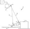
- FIG. 1is a simplified diagram showing an example process control or monitoring system 10 which includes a control room 12 communicating with field devices 14 and 16 through a wireless gateway 13 . Communication between gateway 13 and control room 12 may be over a wired or wireless communication link
- Field device 14is shown coupled to process piping 18 and field device 16 is shown coupled to storage tank 20 .
- devices 14 , 16may be located at any desired location.
- Devices 14 and 16include antennas 22 and 24 , respectively, for transmitting and/or receiving information from antenna 26 associated with wireless gateway 13 .
- Devices 14 and 16communicate using wireless radio frequency (RF) communication links 28 , 29 and 30 with each other and with a remote location such as gateway 13 .
- RFradio frequency
- One example wireless communication protocolis the WirelessHART® protocol in accordance with IEC 62591.
- Field devices 14 and 16include components to provide local (internal) power to the devices without requiring additional wires.
- device 14 and 16can include solar cells and/or batteries for local power.
- the present inventionincludes a wireless field device such as devices 14 and 16 , which includes the ability to capture images of an environment in which the field device 14 , 16 is located using an image capture device.
- a controller within the devicereceives the captured images and generates compressed image information. This compressed image information is transmitted to a remote location using a wireless communication technique. This reduces the amount of power required by the device and also reduces the amount of bandwidth required to send the image information.
- FIG. 2is a simplified block diagram showing field device 14 shown in FIG. 1 in greater detail.
- Field device 14includes an optional transducer 31 , wireless input/output (communication) circuitry 32 , controller 34 , power supply circuit 36 , battery 38 and solar panel 40 .
- the transducer 31can be either a sensor used to sense a process variable or a control element, such as a valve, which is used to control a process variable.
- the wireless communication circuitry 32couples to antenna 22 for communication with gateway 13 over its antenna 26 .
- device 14communicates directly with control room 12 .
- Power supply circuit 36is used to provide power to circuitry within field device 14 .
- the power supply circuitry 36can operate using internal power received from solar cell 40 or power received from battery 38 .
- the power supply circuitry 36can be powered from any type of internal power source that does not require wiring to a remote power source.
- the power supply circuitry 36can be self-contained within the field device 14 or, in some embodiments, be located externally to the field device and positioned proximate to the field device.
- a solar powered unitcan be used to power a transmitter or other field device over a two wire connection which is also used to carry information.
- the power supply circuitrycan also provide wireless communication to a remote location.
- Such configurationsare shown and described in U.S. patent application Ser. No.
- power supply circuitry 36can also be used to charge the battery 38 .
- An image capture device 74is used to capture images of an environment as explained below in more detail.
- FIG. 3is a more detailed block diagram of process device 14 according to an embodiment of the present invention and shows optional transducer 31 configured as a process variable sensor.
- the process variable sensor 31may be positioned within the housing of device 14 or external to the housing as illustrated in FIG. 3 .
- Measurement circuitry 52couples to process variable sensor 31 and is used to perform initial signal processing prior to providing a measurement signal to controller 34 .
- An optional user input 54is shown as operator button in FIG. 3 .
- an optional output devicesuch as LCD display 56 is shown.
- Controller 34is typically a microprocessor based controller and couples to a memory 60 and a clock 62 .
- the clock 62determines the operation speed of digital circuitry within field device 14 and memory 60 is used to store information.
- Memory 60can comprise both permanent and volatile memory and can be used to store data used during processing, programming instructions, calibration information, or other information, data or instructions for use with process device 14 .
- Memory 60also stores image information as described herein.
- FIG. 3also illustrates image capture device 74 in accordance with one example embodiment of the present invention.
- Image capture device 74operates as discussed below in more detail and provides an image output consisting of image information to controller 34 .
- a remote field deviceIn some instances it is desirable to visually monitor the environment surrounding a remote field device. Typically, such monitoring requires that a vehicle be dispatched with service personnel who must drive to a remote location to perform a visual inspection.
- the present inventionprovides for image monitoring of a remote environment 75 which may include process elements such as a flare, pump-jack, pump, tank, or other component proximate field device 14 , 16 at a remote location. This can be used to provide information related to vehicles or personnel in the area, proper operation of equipment such as a pump or well, the presence of a fire or smoke, escaping process fluid, etc.
- Wireless field deviceswhich are capable of operating at remote locations that do not require an external power source are available from, for example, Rosemount Inc. of Chanhassen, Minn. Such devices are configured to measure process variables or obtain other process information and transmit information using wireless communication techniques such as the WirelessHART® protocol.
- wireless communication techniquessuch as the WirelessHART® protocol.
- due to power and bandwidth limitations, such devicesare not well suited for transmitting large quantities of data such as is present in image data. Such transmission requires large power consumption and would rapidly deplete the battery of the device thereby shortening the amount of time the device could be left unattended in the field.
- the present inventionprovides a method and apparatus for providing image information from such a wireless field device.
- the image capture device 74comprises a CCD or a CMOS device.
- the image capture device 74optionally includes a lens to focus a desired region of the surrounding environment 75 onto the device 74 .
- Optional processing circuitrycan be provided which is capable of detecting changes (deltas) in individual pixels or groups of pixels of the device.
- One example image capture device 74is an optical mouse sensor such as the ADNS-5090 by Avago Technologies or OV7995 by Omnivision Technologies. This is an example of a device which performs both image capture as well as detecting changes (deltas) in an image and is an implemented single integrated circuit.
- FIGS. 4A, 4B and 4Care illustrations of an industrial process environment 75 and illustrate operation of one example embodiment of the present invention.
- a reference imageis shown of an oil rig 80 .
- FIG. 4Bthe same reference image is shown and the sun 82 is also visible.
- FIG. 4Can individual 84 can be seen proximate the oil rig in addition to the sun 82 .
- the reference image illustrated in FIG. 4Acan be obtained by image capture device 74 and stored in memory 60 .
- the reference imagemay be taken at a high resolution for enhanced image processing and analysis at a host site.
- the reference imagecan be transmitted at a slow data rate to a remote location such as control room 12 shown in FIG. 1 .
- the reference imageis transferred to the remote location using some means other than RF link 28 , 30 and stored at the remote location as the reference image.
- physical memorysuch as a memory stick can be used to move the image to the control room 12 shown in FIG. 1 .
- a second imageis captured by image capture device 74 such as illustrated in FIG. 4B .
- this imagediffers from the reference image of FIG. 4A in that the sun 82 is visible.
- subsequent imagesmay be taken minutes or even hours apart.
- controller 34need only store those portions (pixels) which have changed.
- the information from the image related to the sun 82may be stored in memory 60 and transmitted to a remote location using wireless communication through antenna 22 . This conserves both memory and transmission bandwidth.
- FIG. 4CYet a second subsequent image is illustrated in FIG. 4C .
- an individual 84is visible proximate the oil rig.
- the imageis captured by the image capture device 74 and controller 34 stores the changes (deltas) in memory 60 for subsequent wireless transmission.
- the delta informationcan be transmitted in near real time, or may be stored in memory 60 for subsequent transmission.
- the image informationmay be transmitted when data traffic on the wireless network 28 , 30 is relatively low, or when additional power is available for transmission.
- the image information which is stored in memory 60 and/or transmitted over wireless communication link 28is preferably compressed in some manner.
- the compressioncan use lossless or lossy techniques. In a lossless technique, no information is lost when the compression occurs. However, a lossy image compression technique results in the compressed image having less information than the original image.
- Example lossless image compression techniquesinclude run length encoding such as is available PCX, BMP, PNG, TGA and TIFF standards, predictive coding and differential pulse code modulation, entropy encoding, adaptive dictionary encoding algorithms (such as LZW which may be implemented in GIF and TIFF formats), deflation or chain codes.
- Lossy image compression techniquesinclude techniques which reduce the color space, chroma sub sampling, transform coding (such as implemented in the JPG standard) and fractal compression. However, the present invention is not limited to these compression techniques.
- the image compressioncan be implemented within the image capture device 74 itself, within controller 34 , or performed by other circuitry in transmitter 14 .
- controller 34operates in accordance with instructions stored in memory 60 which allow it to be “trained” to observe a known environment 75 and transmit event messages when certain events have occurred in the environment 75 . For example, if a flare or a flame is detected in a particular region of the remote environment 75 , a message can be transmitted wirelessly to that effect.
- imagesare captured by image capture device 74 at an increased frame rate during certain events to provide additional images detail of the remote environment 75 .
- the captured imagesmay be of a higher resolution.
- the controller 34can receive instructions wirelessly which increase the rate at which images are captured and/or the resolution of captured images. This command may be generated by another device or may be sent by user.
- the controller 34when a change from the reference image is detected, the controller 34 only transmits information related to the location or region of the reference image in which the change occurred.
- this informationis received at the control system 12 shown in FIG. 2 , the reference image can be displayed to an operator along with information highlighting the region of the environment in which a change was detected. For example, if the highlighted region is at the location of a burner, this information can allow an operator to determine that a flame has been ignited or extinguished.
- the change in a captured image with respect to the reference imagecan be detected within the image capture device 74 itself, within controller 34 , or by other circuitry within transmitter 14 .
- FIG. 5is another example embodiment of wireless controller monitoring system 10 .
- Control room 12is illustrated as including a PC 12 A configured to run an image management application.
- a number of different WirelessHART® devices 16are illustrated which communicate with control room 12 through gateway receiver 13 . Communication between gateway 13 and control room 12 may be over a wired or wireless communication link.
- Field device 14is shown and includes a number of optional additional inputs. For example, a temperature sensor 90 and a current to capacitance interface 92 are shown.
- Optional GPS module 94may be implemented to provide location information to microcontroller 34 which can be used to identify environment 75 image.
- An optional USB interface 98is provided for interfacing with microcontroller 34 .
- memory 60is illustrated as FRAM which is one example of a non-volatile memory.
- the image information which is transmitted to remote locationmay optionally include additional information including real time information related to when the image was obtained, location information related to where the image was obtained, positioning information related to a direction that the image capture device is pointed, other sensor information such as temperature, process variables, etc., information which identifies the process device 14 which captured the image, or other information.
- the image capture device 74can be configured for use in harsh environments. For example, a nano coating be used to help ensure that the image aperture remains clean. Another example coating is titanium dioxide which prevents dirt and contaminants from adhering to glass.
- the image capture device 74can, itself, record information related to the condition of the aperture. For example, a baseline image may be obtained which is of a clean aperture. This can be used to detect when the aperture becomes dirty by comparing a current image with the baseline image and thereby alert an operator, for example, by transmitting information to control room 12 .
- the memory 60 of the transmitter 14can store any number of images or delta information based upon its size and available power.
- Image informationcan be removed from the memory 60 once it has been transmitted.
- a signalis received by process device 14 which indicates that an image has been successfully received at a remote location thereby allowing the stored image to be erased from memory 60 .
- the image informationcan be transmitted continuously, or can be transmitted in a number of different packets, such as through block transfers.
- Image change (delta) informationtypically requires less bandwidth.
- an image processing and management application running on PC 12 Acan be configured to perform object recognition. For example, individuals, vehicles, flames, vapors or gas, smoke, pump position, etc., can be identified.
- the field device 14can obtain and/or transmit image information periodically, when a sufficient delta is detected in an image, or upon receipt of a command. Stored images as well as transmitted images may include time information. Further, the device can be configured to store any number of images based upon receipt of a command from a remote location. A host may request that the field device 14 obtain a series of images at a desired resolution and transmit those images.
- the image capture device 74includes an actuator to reposition the image capture device 74 to perform a pan and/or tilt function
- commandscan be sent to the device to control the positioning of the image capture device 74 .
- the image capture device 74periodically changes position to observe different areas of the remote environment 75 .
- a focusing mechanismis provided with the capture device 74 , this can further be utilized when capturing an image.
- the focusing mechanismcan be used for near field image capture whereby contaminants on the lens or sensor may be detected.
- FIG. 6is a simplified diagram of one example configuration of image capture device 74 .
- Image capture device 74includes an image sensor 120 such as a CCD or the like.
- the image sensor 120is arranged in a two-dimensional array to capture an image of remote environment 75 which is focused using lens 122 .
- lens 122may include optional coatings to reduce debris accumulation.
- An output from sensor 120is provided to an image processor 124 which is related to the sensed image.
- Image processor 124is configured to process the individual pixels from sensor 120 and provide an output to microcontroller 34 discussed above. As also discussed above, in some configurations, processor 124 only provides an output related to changes in the sensed image.
- pan and tilt actuators 126 and 128are provided which can be controlled by microcontroller 34 such that image sensor 122 obtains images from different areas of the remote environment 75 as desired.
- the movementcan be in response to a command, occur periodically at a desired time interval, or in response to an event. For example, if a particular sensor in the process is giving an anomalous reading, the image capture device 74 can be pointed to observe that particular area of the process.
- the inventionincludes recording only changes in a capture image in order to reduce memory requirements and transmission bandwidth.
- captured image datais compressed using image compression techniques. This may include both lossy as well as lossless compression techniques. This also reduces storage and bandwidth requirements.
- any stored image informationcan be removed from the memory 60 . If the storage limit of the memory is reached, older images can be deleted in a first in, first out basis. Large amounts of image data, for example, reference images, can be transferred using multiple blocks or packets sent over the wireless communication link Smaller amounts of image data, for example image delta information, can be transferred using fewer packets. In one configuration, only information related to a region of the image in which a change occurred is transmitted.
- a PC 12 Acan operate an image management application and use to combine a baseline reference image with image delta information. This can be used to reconstruct an image for an operator based upon the baseline reference image and the image delta information.
- the image management applicationcan further be configured to perform object recognition to recognize various objects or actions in the remote environment 75 . Such objects or actions include recognizing people, vehicles, flames, vapor/gas, etc.
- the applicationcan be configured to recognize events such as a flare, people or vehicles entering an area, a flame or explosion, fluid discharge, etc.
- the applicationcan be configured to display a plurality of images on a display to provide an animation viewable by an operator. For example, an operator can configure a selected number of images to be displayed in sequence with a selected starting and ending times.
- image display techniquescan be employed, such as, providing exaggeration to those regions of an image containing motion. Object or action recognition can then be performed on the process video for increased detection sensitivity. This allows the image management application to mathematically exaggerate image change (delta) information to make subtle changes more apparent.
- MITMassachusetts Institute of Technology
- One example techniquehas been developed by the Massachusetts Institute of Technology (MIT) and is described in, “MIT News, researchers amplify variations in video, making the invisible visible, Larry Hardesty, Jun. 22, 2012, http://web.mit.edu/newsoffice/2012/amplifying-invisible0video-0622/html).
- the images transferred over the wireless communication link 28can include additional information such as a time stamp, geographical information, information regarding sensed process variables, information which identifies the portion of the remote environment 75 which is being monitored, information related to a direction at which the image capture device is pointed, etc.
- the compressed image informationis transmitted over the wireless network as packets of information.
- the wireless networkis typically part of a larger network including multiple wireless devices.
- other process related informationsuch as process variables are also transmitted on the same network. It is important that process variables be able to be transmitted.
- the network bandwidthmay be limited thereby reducing the amount of bandwidth available for process variable transmission.
- the bandwidth required to transmit imagesis reduced by sending compressed image data.
- the data packets which contain image informationcan be tagged with priority information that indicates that they have a lower transmission priority than other packets of information on the wireless network such as packets containing information related to process variables.
- the controller 34has sufficient processing power such that image processing may be performed within the field device 14 .
- the devicecan monitor the local environment 75 and transmit event messages when certain events have been observed, such as the presence or absence of a flame, etc.
- an image of the eventis stored in the memory 60 .
- An occurrence of the eventcan be detected by comparing the stored event image with current image data from the image capture device 74 .
- the field device 14can transmit event status information periodically, or only upon the occurrence and detection of an event. As desired, the field device may transmit only the event status information but may also include image information including image delta information. Any image information obtained during an event can be stored in the memory 60 including time stamp information.
- the image management application 12 Aupon receipt of an event status, can control the field device 14 to cause it to collect a series of images for subsequent transmission. The image management application 12 A can verify the event prior to an operator being notified.
- compressed image informationrefers to image information which has been compressed in a manner to consist of less data than original image information.
- the compressioncan be lossless or lossy and includes techniques which simply provide information related to a location in an image in which the image has changed including how much the image has changed in that particular location. It does not include information which simply indicates that something in an image has changed without any information regarding a location.
- image change informationincludes information which indicates that there has been a change in at least some portion of the image, and includes such information which does not have to specifically indicate where in an image a change has occurred.
- Transmission of compressed image information or image change informationcan be triggered by comparing an amount of change to a threshold. If a threshold is exceeded, transmission can be enabled.
- the image capture devicecan be sensitive to any desired wavelength including optical, infrared and ultraviolet. In one aspect, the field device operates using power stored in an internal battery or the like.
Landscapes
- Engineering & Computer Science (AREA)
- Multimedia (AREA)
- Signal Processing (AREA)
- Physics & Mathematics (AREA)
- General Physics & Mathematics (AREA)
- Automation & Control Theory (AREA)
- General Engineering & Computer Science (AREA)
- Manufacturing & Machinery (AREA)
- Quality & Reliability (AREA)
- Closed-Circuit Television Systems (AREA)
- Selective Calling Equipment (AREA)
- Arrangements For Transmission Of Measured Signals (AREA)
Abstract
Description
Claims (23)
Priority Applications (11)
| Application Number | Priority Date | Filing Date | Title |
|---|---|---|---|
| US14/038,090US10638093B2 (en) | 2013-09-26 | 2013-09-26 | Wireless industrial process field device with imaging |
| CN202211688826.2ACN115826535A (en) | 2013-09-26 | 2014-01-20 | Wireless industrial process field device with imaging capability |
| CN201410024656.7ACN104516335A (en) | 2013-09-26 | 2014-01-20 | Wireless Industrial Process Field Devices with Imaging Capabilities |
| EP14761467.1AEP3050293B1 (en) | 2013-09-26 | 2014-08-19 | Wireless industrial process field device with imaging |
| PCT/US2014/051625WO2015047596A1 (en) | 2013-09-26 | 2014-08-19 | Wireless industrial process field device with imaging |
| RU2016116020ARU2631256C1 (en) | 2013-09-26 | 2014-08-19 | Wireless peripheral device of production process with formation of images |
| JP2016517425AJP2016540397A (en) | 2013-09-26 | 2014-08-19 | Wireless industrial process field device using image processing |
| AU2014328666AAU2014328666A1 (en) | 2013-09-26 | 2014-08-19 | Wireless industrial process field device with imaging |
| BR112016006476ABR112016006476A2 (en) | 2013-09-26 | 2014-08-19 | wireless field device, wireless monitoring system, and method |
| CA2923156ACA2923156C (en) | 2013-09-26 | 2014-08-19 | Wireless industrial process field device with imaging |
| AU2017245347AAU2017245347B2 (en) | 2013-09-26 | 2017-10-11 | Wireless industrial process field device with imaging |
Applications Claiming Priority (1)
| Application Number | Priority Date | Filing Date | Title |
|---|---|---|---|
| US14/038,090US10638093B2 (en) | 2013-09-26 | 2013-09-26 | Wireless industrial process field device with imaging |
Publications (2)
| Publication Number | Publication Date |
|---|---|
| US20150085103A1 US20150085103A1 (en) | 2015-03-26 |
| US10638093B2true US10638093B2 (en) | 2020-04-28 |
Family
ID=51493047
Family Applications (1)
| Application Number | Title | Priority Date | Filing Date |
|---|---|---|---|
| US14/038,090Active2035-03-20US10638093B2 (en) | 2013-09-26 | 2013-09-26 | Wireless industrial process field device with imaging |
Country Status (9)
| Country | Link |
|---|---|
| US (1) | US10638093B2 (en) |
| EP (1) | EP3050293B1 (en) |
| JP (1) | JP2016540397A (en) |
| CN (2) | CN115826535A (en) |
| AU (2) | AU2014328666A1 (en) |
| BR (1) | BR112016006476A2 (en) |
| CA (1) | CA2923156C (en) |
| RU (1) | RU2631256C1 (en) |
| WO (1) | WO2015047596A1 (en) |
Families Citing this family (8)
| Publication number | Priority date | Publication date | Assignee | Title |
|---|---|---|---|---|
| US10638093B2 (en)* | 2013-09-26 | 2020-04-28 | Rosemount Inc. | Wireless industrial process field device with imaging |
| US20160036906A1 (en)* | 2014-08-04 | 2016-02-04 | Vixlet LLC | Dynamic adjustment of client thickness |
| US11086025B2 (en)* | 2015-08-13 | 2021-08-10 | Propeller Aerobotics Pty Ltd | Integrated visual geo-referencing target unit and method of operation |
| WO2020086071A1 (en)* | 2018-10-24 | 2020-04-30 | Siemens Energy, Inc. | System and method to automatically optically monitoring field devices and assess state information |
| EP3683743A1 (en)* | 2019-01-17 | 2020-07-22 | Basf Se | Computer-implemented method, system and computer program for providing audit records that relate to technical equipment |
| CN110246157B (en)* | 2019-06-21 | 2020-09-04 | 大庆安瑞达科技开发有限公司 | Oil-gas field equipment production state distinguishing system and method based on big data monitoring |
| CN113341802A (en)* | 2021-06-01 | 2021-09-03 | 江西凯天电力科技发展有限公司 | Intelligent and safe electricity utilization operation and maintenance management system and method |
| JP7713920B2 (en)* | 2022-09-20 | 2025-07-28 | 株式会社Kokusai Electric | Substrate processing apparatus, semiconductor device manufacturing method, and program |
Citations (132)
| Publication number | Priority date | Publication date | Assignee | Title |
|---|---|---|---|---|
| US3857277A (en) | 1972-12-29 | 1974-12-31 | Laval Turbine | Flow indicator |
| JPS52140779A (en) | 1976-05-19 | 1977-11-24 | Daikin Ind Ltd | Methods of discriminating quality of the equipment in hydraulic device |
| JPS5386111A (en) | 1977-01-07 | 1978-07-29 | Toshiba Corp | Monitor device |
| US4306457A (en) | 1978-11-17 | 1981-12-22 | Nippon Electric Co., Ltd. | Liquid meter comprising a circuit for reducing a detection error resulting from a variable flow rate |
| JPS5890882A (en) | 1981-11-24 | 1983-05-30 | Mitsubishi Electric Corp | Elevator monitoring device |
| JPS61136340A (en) | 1984-12-06 | 1986-06-24 | Kubota Ltd | Oil well control method |
| JPS62179647A (en) | 1986-02-03 | 1987-08-06 | Mitsubishi Heavy Ind Ltd | Inner wall defect inspector for high temperature container |
| US4736250A (en) | 1986-11-28 | 1988-04-05 | Tektronix, Inc. | Digital camera frame capture circuit |
| JPS6473880A (en) | 1987-09-14 | 1989-03-20 | Matsushita Electric Works Ltd | Iamge transmission system |
| US4900161A (en) | 1986-12-10 | 1990-02-13 | Fissler Gmbh | System for measuring temperature of a filled vessel on a hot plate |
| US4947247A (en) | 1989-06-20 | 1990-08-07 | Combustion Engineering, Inc. | Displacement measurement apparatus and method for an automated flow rotameter |
| US5056046A (en) | 1989-06-20 | 1991-10-08 | Combustion Engineering, Inc. | Pneumatic operated valve data acquisitioner |
| US5109277A (en) | 1990-06-20 | 1992-04-28 | Quadtek, Inc. | System for generating temperature images with corresponding absolute temperature values |
| US5144430A (en) | 1991-08-09 | 1992-09-01 | North American Philips Corporation | Device and method for generating a video signal oscilloscope trigger signal |
| US5292195A (en) | 1992-09-09 | 1994-03-08 | Martin Marietta Corporation | Thermographic evaluation technique |
| JPH07325900A (en) | 1994-05-31 | 1995-12-12 | Dainippon Printing Co Ltd | Cards and how to use them |
| US5638174A (en) | 1994-05-11 | 1997-06-10 | Xerox Corporation | Fluid sensing apparatus with a rotatable member utilizing different length light pipes for alternately transmitting a light beam |
| US5654977A (en) | 1995-02-02 | 1997-08-05 | Teledyne Industries Inc. | Method and apparatus for real time defect inspection of metal at elevated temperature |
| JPH09265316A (en) | 1996-03-28 | 1997-10-07 | Mitsubishi Electric Corp | Plant equipment inspection device and plant equipment inspection system |
| JPH1047312A (en) | 1996-07-31 | 1998-02-17 | Nkk Corp | How to detect internal leakage of hydraulic cylinder |
| JPH10294933A (en) | 1997-04-18 | 1998-11-04 | Mitsubishi Electric Corp | Video surveillance system |
| JPH1123350A (en) | 1997-06-30 | 1999-01-29 | Hitachi Ltd | Liquid level measuring method and device |
| JPH1175176A (en) | 1997-07-02 | 1999-03-16 | Matsushita Electric Ind Co Ltd | Remote monitoring system and remote monitoring method |
| CN1214958A (en) | 1997-10-03 | 1999-04-28 | 三井化学株式会社 | Fluidized bed polymerization reaction equipment and olefines polymerization reaction method |
| JPH11189603A (en) | 1997-10-03 | 1999-07-13 | Mitsui Chem Inc | Fluidized-bed type polymerization apparatus and polymerization of olefin |
| JPH11218442A (en) | 1997-11-25 | 1999-08-10 | Mitsubishi Electric Corp | Thermal infrared detector array |
| US6000844A (en) | 1997-03-04 | 1999-12-14 | The United States Of America As Represented By The Administrator Of The National Aeronautics And Space Administration | Method and apparatus for the portable identification of material thickness and defects using spatially controlled heat application |
| US6059453A (en) | 1998-04-20 | 2000-05-09 | Rosemount Inc. | Temperature probe with sapphire thermowell |
| JP2000310577A (en) | 1999-04-27 | 2000-11-07 | Toshiba Corp | Leakage amount measurement device and leakage amount measurement method |
| JP2001084031A (en) | 1999-09-10 | 2001-03-30 | Toshiba Corp | Plant monitoring system |
| US6259810B1 (en) | 1997-04-15 | 2001-07-10 | Microsoft Corporation | Method and system of decoding compressed image data |
| JP2001221666A (en) | 2000-02-10 | 2001-08-17 | Rally Master Kk | Variable-area flowmeter with sensor |
| JP2001238198A (en) | 2000-02-23 | 2001-08-31 | Victor Co Of Japan Ltd | Differential camera terminal |
| JP2001256475A (en) | 2001-04-27 | 2001-09-21 | Ced System Inc | System for detecting black smoke |
| US20010042834A1 (en) | 1997-06-06 | 2001-11-22 | Daniel J. Kenway | Defect detection in articles using computer modelled dissipation correction differential time delayed far ir scanning |
| JP2002300569A (en) | 2001-03-30 | 2002-10-11 | Fujitsu General Ltd | Surveillance method and surveillance system using network cameras |
| US6518744B1 (en) | 2000-03-23 | 2003-02-11 | Tektronix, Inc. | General purpose oscilloscope having digital television signal display capability |
| US6573331B1 (en) | 1998-06-10 | 2003-06-03 | Institut Francais Du Petrole | Grafted block polymers containing at least a polyolefin or polydiene sequence comprising a succinimide cycle substituted on nitrogen |
| US6631287B2 (en) | 2001-04-03 | 2003-10-07 | Welch Allyn, Inc. | Infrared thermometer |
| WO2004011935A1 (en) | 2002-07-30 | 2004-02-05 | Xpar Vision B.V. | Analytical system and method for measuring and controlling a production process |
| US20040041538A1 (en) | 2002-08-27 | 2004-03-04 | Vladimir Sklovsky | Power resource management in a portable communication device |
| TWI220364B (en) | 2002-03-29 | 2004-08-11 | Pixart Imaging Inc | Digital camera of automatically monitoring environmental change |
| US20040156549A1 (en)* | 1998-10-01 | 2004-08-12 | Cirrus Logic, Inc. | Feedback scheme for video compression system |
| JP2004288092A (en) | 2003-03-25 | 2004-10-14 | Mitsubishi Electric Corp | Self-powered wireless data collection system |
| US20040218099A1 (en)* | 2003-03-20 | 2004-11-04 | Washington Richard G. | Systems and methods for multi-stream image processing |
| US20050008072A1 (en)* | 2003-06-10 | 2005-01-13 | Walter Angerer | Analog data compression |
| US20050012817A1 (en) | 2003-07-15 | 2005-01-20 | International Business Machines Corporation | Selective surveillance system with active sensor management policies |
| US20050025368A1 (en)* | 2003-06-26 | 2005-02-03 | Arkady Glukhovsky | Device, method, and system for reduced transmission imaging |
| CN2694128Y (en) | 2003-07-04 | 2005-04-20 | 北方工业大学 | Infrared temperature scanning and monitoring system for rotary kiln |
| US20050111696A1 (en) | 2003-11-24 | 2005-05-26 | Baer Richard L. | Imaging surveillance system and method for event detection in low illumination |
| JP2005134357A (en) | 2003-10-28 | 2005-05-26 | Toshiba Corp | Valve leakage detecting system |
| US20050164684A1 (en) | 1999-02-12 | 2005-07-28 | Fisher-Rosemount Systems, Inc. | Wireless handheld communicator in a process control environment |
| US20050220331A1 (en) | 1999-12-14 | 2005-10-06 | Combustion Specialists, Inc. | Sensing system for detection and control of deposition on pendant tubes in recovery and power boilers |
| JP2006031418A (en) | 2004-07-16 | 2006-02-02 | Nec Toshiba Space Systems Ltd | Monitoring system |
| US20060026971A1 (en) | 2004-07-06 | 2006-02-09 | Richard Sharpe | Systems and methods for determining and monitoring wine temperature |
| US20060092153A1 (en) | 2004-10-29 | 2006-05-04 | Chu Hong J | Method for power management in a display |
| US20060148410A1 (en)* | 2005-01-03 | 2006-07-06 | Nelson Richard L | Wireless process field device diagnostics |
| WO2006081154A2 (en) | 2005-01-25 | 2006-08-03 | The Regents Of The University Of California | Wireless sensing node powered by energy conversion from sensed system |
| US20060278827A1 (en) | 2005-06-08 | 2006-12-14 | Rosemount, Inc. | Process field device with infrared sensors |
| CN1882078A (en) | 2005-06-17 | 2006-12-20 | 株式会社日立建筑系统 | Image error detection device for monitoring camera |
| US20070019077A1 (en)* | 2003-06-27 | 2007-01-25 | Park Sang R | Portable surveillance camera and personal surveillance system using the same |
| US20070052804A1 (en) | 2005-09-07 | 2007-03-08 | Money James K | Mobile video surveillance system and method |
| US20070073439A1 (en) | 2005-09-23 | 2007-03-29 | Babak Habibi | System and method of visual tracking |
| JP2007108836A (en) | 2005-10-11 | 2007-04-26 | Denso Corp | Monitoring control device and monitoring control method |
| US20070125949A1 (en) | 2004-10-18 | 2007-06-07 | Takahiko Murata | Infrared sensor and infrared sensor array |
| US7248297B2 (en) | 2001-11-30 | 2007-07-24 | The Board Of Trustees Of The Leland Stanford Junior University | Integrated color pixel (ICP) |
| CN101014091A (en) | 2006-02-02 | 2007-08-08 | 佳能株式会社 | Image pickup apparatus and control method thereof |
| CN101019419A (en) | 2004-09-13 | 2007-08-15 | 佳能株式会社 | Image sensing device and control method thereof |
| CN101046375A (en) | 2007-03-16 | 2007-10-03 | 邯郸市清华华康电力电子有限公司 | Real-time detecting and early-warning system for inclination of electric power tower |
| WO2007139123A1 (en) | 2006-05-25 | 2007-12-06 | Panasonic Electric Works Co., Ltd. | Infrared sensor |
| US7372485B1 (en) | 1999-06-08 | 2008-05-13 | Lightsurf Technologies, Inc. | Digital camera device and methodology for distributed processing and wireless transmission of digital images |
| US20080165195A1 (en)* | 2007-01-06 | 2008-07-10 | Outland Research, Llc | Method, apparatus, and software for animated self-portraits |
| US7407323B2 (en) | 2006-02-03 | 2008-08-05 | Ge Infrastructure Sensing Inc. | Methods and systems for determining temperature of an object |
| US7409867B2 (en) | 2006-05-23 | 2008-08-12 | Rosemount Inc. | Pressure sensor using light source |
| CN101277383A (en) | 2007-03-27 | 2008-10-01 | 佳能株式会社 | Image processing apparatus, control method, and image capturing apparatus |
| JP2008257513A (en) | 2007-04-05 | 2008-10-23 | Hitachi Ltd | Abnormal condition monitoring device and elevator system |
| US20080278145A1 (en) | 2007-05-07 | 2008-11-13 | Fabian Wenger | Process measurement instrument adapted for wireless communication |
| US7472215B1 (en) | 1999-03-31 | 2008-12-30 | International Business Machines Corporation | Portable computer system with thermal enhancements and multiple power modes of operation |
| US20090078047A1 (en) | 2007-09-21 | 2009-03-26 | Cosense, Inc. | Non-invasive multi-function sensor system |
| CN101460971A (en) | 2006-06-08 | 2009-06-17 | 富士通株式会社 | Uncleanness detecting device |
| WO2009074708A1 (en) | 2007-10-11 | 2009-06-18 | Euroelektro International Oy | Use of a smart camera for controlling an industrial ac drive |
| JP2009210042A (en) | 2008-03-05 | 2009-09-17 | Shikoku Res Inst Inc | Actuated valve diagnosis device using outer surface condition detecting sensor |
| US20090249405A1 (en) | 2008-03-31 | 2009-10-01 | Broadcom Corporation | Video transmission system with edge device for adjusting video streams based on device parameters and methods for use therewith |
| CN201322868Y (en) | 2008-11-21 | 2009-10-07 | 广西大学 | Intelligent remote base station monitoring system |
| US20090285259A1 (en) | 2008-05-14 | 2009-11-19 | General Electric Company | System and method for thermal inspection of objects |
| CN101600046A (en) | 2008-06-05 | 2009-12-09 | 佳能株式会社 | Picture pick-up device and control method thereof |
| EP2130187A1 (en) | 2007-03-28 | 2009-12-09 | Honeywell International Inc. | Self-contained wireless security sensor collective system and method |
| US20100013918A1 (en) | 2004-11-03 | 2010-01-21 | Pedagog Limited | Viewing system |
| CN101647216A (en) | 2007-03-05 | 2010-02-10 | 罗斯蒙德公司 | Mode Selectable Field Transmitters |
| CN101681161A (en) | 2007-03-26 | 2010-03-24 | 霍尼韦尔国际公司 | Apparatus and method for visualizaiton of control techniques in a process control system |
| CN101685295A (en) | 2007-09-27 | 2010-03-31 | 洛克威尔自动控制技术股份有限公司 | Dynamically generating visual images from contextual and status information in an industrial automation environment |
| US20100220180A1 (en) | 2006-09-19 | 2010-09-02 | Capso Vision, Inc. | Capture Control for in vivo Camera |
| US7809379B2 (en) | 2004-06-21 | 2010-10-05 | Lg Electronics Inc. | Multi-mode mobile terminal and method of triggering communication service using position information thereof |
| JP2010536092A (en) | 2007-08-06 | 2010-11-25 | ローズマウント インコーポレイテッド | Process variable transmitter with acceleration sensor |
| US7852271B2 (en) | 2006-09-28 | 2010-12-14 | Rosemount Inc. | Wireless field device with antenna for industrial locations |
| JP2010283444A (en) | 2009-06-02 | 2010-12-16 | Sekyurion Nijuyon Kk | Camera device and video recording system |
| WO2011004020A2 (en) | 2009-07-10 | 2011-01-13 | St-Ericsson (Grenoble) Sas | Detection of usb attachment |
| JP2011185926A (en) | 2010-03-05 | 2011-09-22 | General Electric Co <Ge> | Thermal measurement system and method for leak detection |
| US20110230942A1 (en) | 2008-12-01 | 2011-09-22 | The Johns Hopkins University | High-resolution infrared imaging for enhanced detection, diagnosis, and treatment of cutaneous lesions |
| JP2011209033A (en) | 2010-03-29 | 2011-10-20 | Pan Pacific Copper Co Ltd | Inspection method for scale state in pipe |
| WO2011137264A1 (en) | 2010-04-28 | 2011-11-03 | Mettler-Toledo, Inc. | Thermal imaging of molded objects |
| US20110317066A1 (en)* | 2008-12-23 | 2011-12-29 | Thales | Interactive System and Method for Transmitting Key Images Selected from a Video Stream Over a Low Bandwidth Network |
| US20120025081A1 (en) | 2010-07-23 | 2012-02-02 | Bruker Optik Gmbh | IR spectrometer with non-contact temperature measurement |
| US20120041582A1 (en) | 2010-08-12 | 2012-02-16 | Wallace Thomas C | Wireless adapter with process diagnostics |
| US8121078B2 (en) | 2006-11-20 | 2012-02-21 | Micropower Technologies, Inc. | Wireless network camera systems |
| JP2012037519A (en) | 2010-08-05 | 2012-02-23 | General Electric Co <Ge> | Heat measurement system for detecting malfunction in power generation system |
| JP2012058093A (en) | 2010-09-09 | 2012-03-22 | Mitsubishi Electric Building Techno Service Co Ltd | Gas leakage detector |
| US20120109342A1 (en) | 2005-10-26 | 2012-05-03 | Braun Scott D | Wireless Industrial Control User Interface With Configurable Software Capabilities |
| CN102483618A (en) | 2010-07-28 | 2012-05-30 | 费希尔-罗斯蒙德系统公司 | Intrinsically Safe Handheld Field Maintenance Tool with Image and/or Sound Capture |
| US20120157009A1 (en) | 2006-10-24 | 2012-06-21 | Omega Engineering, Inc. | Universal wireless transceiver |
| US20120161958A1 (en) | 2010-12-28 | 2012-06-28 | Crossbow Technology Inc. | Power management in wireless tracking device operating with restricted power source |
| JP2012175631A (en) | 2011-02-24 | 2012-09-10 | Mitsubishi Electric Corp | Video monitoring device |
| US8310541B2 (en) | 2007-09-26 | 2012-11-13 | Xerox Corporation | System and method for monitoring a printing system using a camera |
| CN102830669A (en) | 2012-05-31 | 2012-12-19 | 山东电力集团公司青岛供电公司 | A monitoring system for power distribution substation |
| WO2013006307A1 (en) | 2011-07-07 | 2013-01-10 | Rosemount, Inc. | Wireless field device with removavble power source |
| JP2013009079A (en) | 2011-06-23 | 2013-01-10 | Seiko Instruments Inc | Terminal device, communication system and terminal device activation method |
| WO2013009715A1 (en) | 2011-07-08 | 2013-01-17 | Schlumberger Canada Limited | System and method for determining a health condition of wellsite equipment |
| CN102999022A (en) | 2011-09-14 | 2013-03-27 | Abb研究有限公司 | Method and system for controlling an industrial process |
| US20130085688A1 (en) | 2011-09-30 | 2013-04-04 | Craig Miller | Water flow sensor and monitoring system comprising a water flow sensor |
| US20130099922A1 (en) | 2011-10-24 | 2013-04-25 | Andrew Lohbihler | Motion and Area Monitoring System and Method |
| US20130120561A1 (en) | 2011-11-14 | 2013-05-16 | Societe De Technologie Michelin | Infrared inspection of metallic web structures |
| US20130163812A1 (en)* | 2011-12-22 | 2013-06-27 | Ricoh Company, Ltd. | Information processor, information processing method, and recording medium |
| US20130176418A1 (en) | 2012-01-10 | 2013-07-11 | Achalesh Kumar Pandey | Continuous infrared thermography monitoring and life management system for heat recovery steam generators |
| US20130222608A1 (en) | 2012-02-29 | 2013-08-29 | Apple Inc. | Imaging sensor anomalous pixel column detection and calibration |
| US8538560B2 (en) | 2004-04-29 | 2013-09-17 | Rosemount Inc. | Wireless power and communication unit for process field devices |
| US20130250125A1 (en) | 2009-03-02 | 2013-09-26 | Flir Systems, Inc. | Thermal image frame capture using de-aligned sensor array |
| US20130294478A1 (en) | 2012-05-01 | 2013-11-07 | Access Business Group International Llc | Device and method for testing block filters |
| US20140003465A1 (en) | 2012-06-29 | 2014-01-02 | Rosemount Inc. | Industrial process temperature transmitter with sensor stress diagnostics |
| CN103947170A (en) | 2011-11-21 | 2014-07-23 | 英特尔公司 | Wireless device and method for low power and low data rate operation |
| US20150116482A1 (en)* | 2012-05-29 | 2015-04-30 | Abb Research Ltd | Object inspection in an industrial plant |
| US20150130927A1 (en) | 2012-05-16 | 2015-05-14 | Isra Vision Ag | Method and a device for the inspection of surfaces of an examined object |
| CN204350309U (en) | 2014-09-29 | 2015-05-20 | 罗斯蒙特公司 | Wireless industrial process monitor and wireless supervisory control system |
Family Cites Families (4)
| Publication number | Priority date | Publication date | Assignee | Title |
|---|---|---|---|---|
| JP2001333416A (en)* | 2000-05-19 | 2001-11-30 | Fujitsu General Ltd | Network surveillance camera system |
| JP4109879B2 (en)* | 2002-03-01 | 2008-07-02 | キヤノン株式会社 | Image distribution system, communication apparatus, distribution apparatus, control method thereof, and storage medium |
| JP2005286474A (en)* | 2004-03-29 | 2005-10-13 | Hitachi Ltd | Communication terminal |
| US10638093B2 (en)* | 2013-09-26 | 2020-04-28 | Rosemount Inc. | Wireless industrial process field device with imaging |
- 2013
- 2013-09-26USUS14/038,090patent/US10638093B2/enactiveActive
- 2014
- 2014-01-20CNCN202211688826.2Apatent/CN115826535A/enactivePending
- 2014-01-20CNCN201410024656.7Apatent/CN104516335A/enactivePending
- 2014-08-19RURU2016116020Apatent/RU2631256C1/ennot_activeIP Right Cessation
- 2014-08-19EPEP14761467.1Apatent/EP3050293B1/enactiveActive
- 2014-08-19BRBR112016006476Apatent/BR112016006476A2/ennot_activeIP Right Cessation
- 2014-08-19WOPCT/US2014/051625patent/WO2015047596A1/enactiveApplication Filing
- 2014-08-19JPJP2016517425Apatent/JP2016540397A/enactivePending
- 2014-08-19CACA2923156Apatent/CA2923156C/enactiveActive
- 2014-08-19AUAU2014328666Apatent/AU2014328666A1/ennot_activeAbandoned
- 2017
- 2017-10-11AUAU2017245347Apatent/AU2017245347B2/ennot_activeCeased
Patent Citations (167)
| Publication number | Priority date | Publication date | Assignee | Title |
|---|---|---|---|---|
| US3857277A (en) | 1972-12-29 | 1974-12-31 | Laval Turbine | Flow indicator |
| JPS52140779A (en) | 1976-05-19 | 1977-11-24 | Daikin Ind Ltd | Methods of discriminating quality of the equipment in hydraulic device |
| JPS5386111A (en) | 1977-01-07 | 1978-07-29 | Toshiba Corp | Monitor device |
| US4306457A (en) | 1978-11-17 | 1981-12-22 | Nippon Electric Co., Ltd. | Liquid meter comprising a circuit for reducing a detection error resulting from a variable flow rate |
| JPS5890882A (en) | 1981-11-24 | 1983-05-30 | Mitsubishi Electric Corp | Elevator monitoring device |
| JPS61136340A (en) | 1984-12-06 | 1986-06-24 | Kubota Ltd | Oil well control method |
| JPS62179647A (en) | 1986-02-03 | 1987-08-06 | Mitsubishi Heavy Ind Ltd | Inner wall defect inspector for high temperature container |
| US4736250A (en) | 1986-11-28 | 1988-04-05 | Tektronix, Inc. | Digital camera frame capture circuit |
| US4900161A (en) | 1986-12-10 | 1990-02-13 | Fissler Gmbh | System for measuring temperature of a filled vessel on a hot plate |
| JPS6473880A (en) | 1987-09-14 | 1989-03-20 | Matsushita Electric Works Ltd | Iamge transmission system |
| US4947247A (en) | 1989-06-20 | 1990-08-07 | Combustion Engineering, Inc. | Displacement measurement apparatus and method for an automated flow rotameter |
| US5056046A (en) | 1989-06-20 | 1991-10-08 | Combustion Engineering, Inc. | Pneumatic operated valve data acquisitioner |
| US5109277A (en) | 1990-06-20 | 1992-04-28 | Quadtek, Inc. | System for generating temperature images with corresponding absolute temperature values |
| US5144430A (en) | 1991-08-09 | 1992-09-01 | North American Philips Corporation | Device and method for generating a video signal oscilloscope trigger signal |
| US5292195A (en) | 1992-09-09 | 1994-03-08 | Martin Marietta Corporation | Thermographic evaluation technique |
| US5638174A (en) | 1994-05-11 | 1997-06-10 | Xerox Corporation | Fluid sensing apparatus with a rotatable member utilizing different length light pipes for alternately transmitting a light beam |
| JPH07325900A (en) | 1994-05-31 | 1995-12-12 | Dainippon Printing Co Ltd | Cards and how to use them |
| US5654977A (en) | 1995-02-02 | 1997-08-05 | Teledyne Industries Inc. | Method and apparatus for real time defect inspection of metal at elevated temperature |
| JPH09265316A (en) | 1996-03-28 | 1997-10-07 | Mitsubishi Electric Corp | Plant equipment inspection device and plant equipment inspection system |
| JPH1047312A (en) | 1996-07-31 | 1998-02-17 | Nkk Corp | How to detect internal leakage of hydraulic cylinder |
| US6000844A (en) | 1997-03-04 | 1999-12-14 | The United States Of America As Represented By The Administrator Of The National Aeronautics And Space Administration | Method and apparatus for the portable identification of material thickness and defects using spatially controlled heat application |
| US6259810B1 (en) | 1997-04-15 | 2001-07-10 | Microsoft Corporation | Method and system of decoding compressed image data |
| JPH10294933A (en) | 1997-04-18 | 1998-11-04 | Mitsubishi Electric Corp | Video surveillance system |
| US6346704B2 (en) | 1997-06-06 | 2002-02-12 | Osb Scan Inc. | Defect detection in articles using computer modelled dissipation correction differential time delayed far IR scanning |
| US20010042834A1 (en) | 1997-06-06 | 2001-11-22 | Daniel J. Kenway | Defect detection in articles using computer modelled dissipation correction differential time delayed far ir scanning |
| JPH1123350A (en) | 1997-06-30 | 1999-01-29 | Hitachi Ltd | Liquid level measuring method and device |
| JPH1175176A (en) | 1997-07-02 | 1999-03-16 | Matsushita Electric Ind Co Ltd | Remote monitoring system and remote monitoring method |
| US6461573B1 (en) | 1997-10-03 | 2002-10-08 | Mitsui Chemicals, Inc. | Fluidized bed polymerization apparatus having temperature distribution monitoring |
| US20030027949A1 (en) | 1997-10-03 | 2003-02-06 | Mitsui Chemicals, Inc. | Fluidized bed polymerization apparatus and an olefin polymerization process |
| JPH11189603A (en) | 1997-10-03 | 1999-07-13 | Mitsui Chem Inc | Fluidized-bed type polymerization apparatus and polymerization of olefin |
| CN1214958A (en) | 1997-10-03 | 1999-04-28 | 三井化学株式会社 | Fluidized bed polymerization reaction equipment and olefines polymerization reaction method |
| JPH11218442A (en) | 1997-11-25 | 1999-08-10 | Mitsubishi Electric Corp | Thermal infrared detector array |
| US6059453A (en) | 1998-04-20 | 2000-05-09 | Rosemount Inc. | Temperature probe with sapphire thermowell |
| US6573331B1 (en) | 1998-06-10 | 2003-06-03 | Institut Francais Du Petrole | Grafted block polymers containing at least a polyolefin or polydiene sequence comprising a succinimide cycle substituted on nitrogen |
| US20040156549A1 (en)* | 1998-10-01 | 2004-08-12 | Cirrus Logic, Inc. | Feedback scheme for video compression system |
| US20050164684A1 (en) | 1999-02-12 | 2005-07-28 | Fisher-Rosemount Systems, Inc. | Wireless handheld communicator in a process control environment |
| US7472215B1 (en) | 1999-03-31 | 2008-12-30 | International Business Machines Corporation | Portable computer system with thermal enhancements and multiple power modes of operation |
| JP2000310577A (en) | 1999-04-27 | 2000-11-07 | Toshiba Corp | Leakage amount measurement device and leakage amount measurement method |
| US7372485B1 (en) | 1999-06-08 | 2008-05-13 | Lightsurf Technologies, Inc. | Digital camera device and methodology for distributed processing and wireless transmission of digital images |
| JP2001084031A (en) | 1999-09-10 | 2001-03-30 | Toshiba Corp | Plant monitoring system |
| US20050220331A1 (en) | 1999-12-14 | 2005-10-06 | Combustion Specialists, Inc. | Sensing system for detection and control of deposition on pendant tubes in recovery and power boilers |
| JP2001221666A (en) | 2000-02-10 | 2001-08-17 | Rally Master Kk | Variable-area flowmeter with sensor |
| JP2001238198A (en) | 2000-02-23 | 2001-08-31 | Victor Co Of Japan Ltd | Differential camera terminal |
| US6518744B1 (en) | 2000-03-23 | 2003-02-11 | Tektronix, Inc. | General purpose oscilloscope having digital television signal display capability |
| JP2002300569A (en) | 2001-03-30 | 2002-10-11 | Fujitsu General Ltd | Surveillance method and surveillance system using network cameras |
| US6631287B2 (en) | 2001-04-03 | 2003-10-07 | Welch Allyn, Inc. | Infrared thermometer |
| AU2002256070B2 (en) | 2001-04-03 | 2006-05-11 | Welch Allyn, Inc. | Infrared thermometer |
| JP2001256475A (en) | 2001-04-27 | 2001-09-21 | Ced System Inc | System for detecting black smoke |
| US7248297B2 (en) | 2001-11-30 | 2007-07-24 | The Board Of Trustees Of The Leland Stanford Junior University | Integrated color pixel (ICP) |
| TWI220364B (en) | 2002-03-29 | 2004-08-11 | Pixart Imaging Inc | Digital camera of automatically monitoring environmental change |
| WO2004011935A1 (en) | 2002-07-30 | 2004-02-05 | Xpar Vision B.V. | Analytical system and method for measuring and controlling a production process |
| US20040041538A1 (en) | 2002-08-27 | 2004-03-04 | Vladimir Sklovsky | Power resource management in a portable communication device |
| US20040218099A1 (en)* | 2003-03-20 | 2004-11-04 | Washington Richard G. | Systems and methods for multi-stream image processing |
| JP2004288092A (en) | 2003-03-25 | 2004-10-14 | Mitsubishi Electric Corp | Self-powered wireless data collection system |
| US20050008072A1 (en)* | 2003-06-10 | 2005-01-13 | Walter Angerer | Analog data compression |
| US20050025368A1 (en)* | 2003-06-26 | 2005-02-03 | Arkady Glukhovsky | Device, method, and system for reduced transmission imaging |
| US20070019077A1 (en)* | 2003-06-27 | 2007-01-25 | Park Sang R | Portable surveillance camera and personal surveillance system using the same |
| CN2694128Y (en) | 2003-07-04 | 2005-04-20 | 北方工业大学 | Infrared temperature scanning and monitoring system for rotary kiln |
| US20050012817A1 (en) | 2003-07-15 | 2005-01-20 | International Business Machines Corporation | Selective surveillance system with active sensor management policies |
| JP2005134357A (en) | 2003-10-28 | 2005-05-26 | Toshiba Corp | Valve leakage detecting system |
| US20050111696A1 (en) | 2003-11-24 | 2005-05-26 | Baer Richard L. | Imaging surveillance system and method for event detection in low illumination |
| US8538560B2 (en) | 2004-04-29 | 2013-09-17 | Rosemount Inc. | Wireless power and communication unit for process field devices |
| US7809379B2 (en) | 2004-06-21 | 2010-10-05 | Lg Electronics Inc. | Multi-mode mobile terminal and method of triggering communication service using position information thereof |
| US20060026971A1 (en) | 2004-07-06 | 2006-02-09 | Richard Sharpe | Systems and methods for determining and monitoring wine temperature |
| JP2006031418A (en) | 2004-07-16 | 2006-02-02 | Nec Toshiba Space Systems Ltd | Monitoring system |
| US7636114B2 (en) | 2004-09-13 | 2009-12-22 | Canon Kabuhsiki Kaisha | Image sensing apparatus and control method capable of performing dust correction |
| CN101019419A (en) | 2004-09-13 | 2007-08-15 | 佳能株式会社 | Image sensing device and control method thereof |
| US20070125949A1 (en) | 2004-10-18 | 2007-06-07 | Takahiko Murata | Infrared sensor and infrared sensor array |
| US20060092153A1 (en) | 2004-10-29 | 2006-05-04 | Chu Hong J | Method for power management in a display |
| US20100013918A1 (en) | 2004-11-03 | 2010-01-21 | Pedagog Limited | Viewing system |
| RU2372667C2 (en) | 2005-01-03 | 2009-11-10 | Роузмаут Инк. | Diagnostic means of wireless field device for manufacturing process |
| US7680460B2 (en) | 2005-01-03 | 2010-03-16 | Rosemount Inc. | Wireless process field device diagnostics |
| US20060148410A1 (en)* | 2005-01-03 | 2006-07-06 | Nelson Richard L | Wireless process field device diagnostics |
| JP2008527493A (en) | 2005-01-03 | 2008-07-24 | ローズマウント インコーポレイテッド | Wireless process field device diagnostics |
| WO2006081154A3 (en) | 2005-01-25 | 2007-09-20 | Univ California | Wireless sensing node powered by energy conversion from sensed system |
| WO2006081154A2 (en) | 2005-01-25 | 2006-08-03 | The Regents Of The University Of California | Wireless sensing node powered by energy conversion from sensed system |
| US7768425B2 (en) | 2005-01-25 | 2010-08-03 | The Regents Of The University Of California | Wireless sensing node powered by energy conversion from sensed system |
| US7466240B2 (en) | 2005-01-25 | 2008-12-16 | The Retents Of The University Of California | Wireless sensing node powered by energy conversion from sensed system |
| US20060278827A1 (en) | 2005-06-08 | 2006-12-14 | Rosemount, Inc. | Process field device with infrared sensors |
| US7208735B2 (en) | 2005-06-08 | 2007-04-24 | Rosemount, Inc. | Process field device with infrared sensors |
| CN1882078A (en) | 2005-06-17 | 2006-12-20 | 株式会社日立建筑系统 | Image error detection device for monitoring camera |
| US20070052804A1 (en) | 2005-09-07 | 2007-03-08 | Money James K | Mobile video surveillance system and method |
| US20070073439A1 (en) | 2005-09-23 | 2007-03-29 | Babak Habibi | System and method of visual tracking |
| JP2007108836A (en) | 2005-10-11 | 2007-04-26 | Denso Corp | Monitoring control device and monitoring control method |
| US20120109342A1 (en) | 2005-10-26 | 2012-05-03 | Braun Scott D | Wireless Industrial Control User Interface With Configurable Software Capabilities |
| US7852383B2 (en) | 2006-02-02 | 2010-12-14 | Canon Kabushiki Kaisha | Image pickup apparatus |
| CN101014091A (en) | 2006-02-02 | 2007-08-08 | 佳能株式会社 | Image pickup apparatus and control method thereof |
| US7407323B2 (en) | 2006-02-03 | 2008-08-05 | Ge Infrastructure Sensing Inc. | Methods and systems for determining temperature of an object |
| US7409867B2 (en) | 2006-05-23 | 2008-08-12 | Rosemount Inc. | Pressure sensor using light source |
| WO2007139123A1 (en) | 2006-05-25 | 2007-12-06 | Panasonic Electric Works Co., Ltd. | Infrared sensor |
| CN101460971A (en) | 2006-06-08 | 2009-06-17 | 富士通株式会社 | Uncleanness detecting device |
| US8098302B2 (en) | 2006-06-08 | 2012-01-17 | Fujitsu Limited | Stain detection system |
| US20100220180A1 (en) | 2006-09-19 | 2010-09-02 | Capso Vision, Inc. | Capture Control for in vivo Camera |
| US7852271B2 (en) | 2006-09-28 | 2010-12-14 | Rosemount Inc. | Wireless field device with antenna for industrial locations |
| RU2419926C2 (en) | 2006-09-28 | 2011-05-27 | Роузмаунт, Инк. | Wireless field device with antenna for industrial locations |
| US20120157009A1 (en) | 2006-10-24 | 2012-06-21 | Omega Engineering, Inc. | Universal wireless transceiver |
| US8121078B2 (en) | 2006-11-20 | 2012-02-21 | Micropower Technologies, Inc. | Wireless network camera systems |
| US20080165195A1 (en)* | 2007-01-06 | 2008-07-10 | Outland Research, Llc | Method, apparatus, and software for animated self-portraits |
| CN101647216A (en) | 2007-03-05 | 2010-02-10 | 罗斯蒙德公司 | Mode Selectable Field Transmitters |
| CN101046375A (en) | 2007-03-16 | 2007-10-03 | 邯郸市清华华康电力电子有限公司 | Real-time detecting and early-warning system for inclination of electric power tower |
| US8108790B2 (en) | 2007-03-26 | 2012-01-31 | Honeywell International Inc. | Apparatus and method for visualization of control techniques in a process control system |
| CN101681161A (en) | 2007-03-26 | 2010-03-24 | 霍尼韦尔国际公司 | Apparatus and method for visualizaiton of control techniques in a process control system |
| US8208752B2 (en) | 2007-03-27 | 2012-06-26 | Canon Kabushiki Kaisha | Image processing apparatus, control method therefor, program, storage medium, and image capturing apparatus |
| CN101277383A (en) | 2007-03-27 | 2008-10-01 | 佳能株式会社 | Image processing apparatus, control method, and image capturing apparatus |
| EP2130187A1 (en) | 2007-03-28 | 2009-12-09 | Honeywell International Inc. | Self-contained wireless security sensor collective system and method |
| JP2008257513A (en) | 2007-04-05 | 2008-10-23 | Hitachi Ltd | Abnormal condition monitoring device and elevator system |
| WO2008136752A1 (en) | 2007-05-07 | 2008-11-13 | Rosemount Tank Radar Ab | Process measurement instrument adapted for wireless communication |
| US20080278145A1 (en) | 2007-05-07 | 2008-11-13 | Fabian Wenger | Process measurement instrument adapted for wireless communication |
| US8898036B2 (en) | 2007-08-06 | 2014-11-25 | Rosemount Inc. | Process variable transmitter with acceleration sensor |
| JP2010536092A (en) | 2007-08-06 | 2010-11-25 | ローズマウント インコーポレイテッド | Process variable transmitter with acceleration sensor |
| US20090078047A1 (en) | 2007-09-21 | 2009-03-26 | Cosense, Inc. | Non-invasive multi-function sensor system |
| US8310541B2 (en) | 2007-09-26 | 2012-11-13 | Xerox Corporation | System and method for monitoring a printing system using a camera |
| CN101685295A (en) | 2007-09-27 | 2010-03-31 | 洛克威尔自动控制技术股份有限公司 | Dynamically generating visual images from contextual and status information in an industrial automation environment |
| US8191005B2 (en) | 2007-09-27 | 2012-05-29 | Rockwell Automation Technologies, Inc. | Dynamically generating visualizations in industrial automation environment as a function of context and state information |
| WO2009074708A1 (en) | 2007-10-11 | 2009-06-18 | Euroelektro International Oy | Use of a smart camera for controlling an industrial ac drive |
| JP2009210042A (en) | 2008-03-05 | 2009-09-17 | Shikoku Res Inst Inc | Actuated valve diagnosis device using outer surface condition detecting sensor |
| US20090249405A1 (en) | 2008-03-31 | 2009-10-01 | Broadcom Corporation | Video transmission system with edge device for adjusting video streams based on device parameters and methods for use therewith |
| US20090285259A1 (en) | 2008-05-14 | 2009-11-19 | General Electric Company | System and method for thermal inspection of objects |
| CN101600046A (en) | 2008-06-05 | 2009-12-09 | 佳能株式会社 | Picture pick-up device and control method thereof |
| CN201322868Y (en) | 2008-11-21 | 2009-10-07 | 广西大学 | Intelligent remote base station monitoring system |
| US20110230942A1 (en) | 2008-12-01 | 2011-09-22 | The Johns Hopkins University | High-resolution infrared imaging for enhanced detection, diagnosis, and treatment of cutaneous lesions |
| US20110317066A1 (en)* | 2008-12-23 | 2011-12-29 | Thales | Interactive System and Method for Transmitting Key Images Selected from a Video Stream Over a Low Bandwidth Network |
| US20130250125A1 (en) | 2009-03-02 | 2013-09-26 | Flir Systems, Inc. | Thermal image frame capture using de-aligned sensor array |
| JP2010283444A (en) | 2009-06-02 | 2010-12-16 | Sekyurion Nijuyon Kk | Camera device and video recording system |
| WO2011004020A2 (en) | 2009-07-10 | 2011-01-13 | St-Ericsson (Grenoble) Sas | Detection of usb attachment |
| US8410946B2 (en) | 2010-03-05 | 2013-04-02 | General Electric Company | Thermal measurement system and method for leak detection |
| JP2011185926A (en) | 2010-03-05 | 2011-09-22 | General Electric Co <Ge> | Thermal measurement system and method for leak detection |
| JP2011209033A (en) | 2010-03-29 | 2011-10-20 | Pan Pacific Copper Co Ltd | Inspection method for scale state in pipe |
| WO2011137264A1 (en) | 2010-04-28 | 2011-11-03 | Mettler-Toledo, Inc. | Thermal imaging of molded objects |
| US20120025081A1 (en) | 2010-07-23 | 2012-02-02 | Bruker Optik Gmbh | IR spectrometer with non-contact temperature measurement |
| CN102483618A (en) | 2010-07-28 | 2012-05-30 | 费希尔-罗斯蒙德系统公司 | Intrinsically Safe Handheld Field Maintenance Tool with Image and/or Sound Capture |
| US9201414B2 (en) | 2010-07-28 | 2015-12-01 | Fisher-Rosemount Systems, Inc. | Intrinsically-safe handheld field maintenance tool with image and/or sound capture |
| JP2012037519A (en) | 2010-08-05 | 2012-02-23 | General Electric Co <Ge> | Heat measurement system for detecting malfunction in power generation system |
| US9019108B2 (en) | 2010-08-05 | 2015-04-28 | General Electric Company | Thermal measurement system for fault detection within a power generation system |
| JP2013533570A (en) | 2010-08-12 | 2013-08-22 | ローズマウント インコーポレイテッド | Wireless adapter with process diagnostics |
| US20120041582A1 (en) | 2010-08-12 | 2012-02-16 | Wallace Thomas C | Wireless adapter with process diagnostics |
| JP2012058093A (en) | 2010-09-09 | 2012-03-22 | Mitsubishi Electric Building Techno Service Co Ltd | Gas leakage detector |
| US9696429B2 (en) | 2010-12-28 | 2017-07-04 | Fedex Corporate Services, Inc. | Power management in wireless tracking device operating with restricted power source |
| CN103380446A (en) | 2010-12-28 | 2013-10-30 | 莫戈公司 | Power management in wireless tracking device operating with restricted power source |
| US20120161958A1 (en) | 2010-12-28 | 2012-06-28 | Crossbow Technology Inc. | Power management in wireless tracking device operating with restricted power source |
| JP2012175631A (en) | 2011-02-24 | 2012-09-10 | Mitsubishi Electric Corp | Video monitoring device |
| JP2013009079A (en) | 2011-06-23 | 2013-01-10 | Seiko Instruments Inc | Terminal device, communication system and terminal device activation method |
| US20140128118A1 (en) | 2011-06-23 | 2014-05-08 | Seiko Instruments Inc. | Terminal device, communication system and method of activating terminal device |
| US9247374B2 (en) | 2011-06-23 | 2016-01-26 | Seiko Instruments Inc. | Terminal device, communication system and method of activating terminal device |
| US8706448B2 (en) | 2011-07-07 | 2014-04-22 | Rosemount Inc. | Wireless field device with removable power source |
| JP2014523033A (en) | 2011-07-07 | 2014-09-08 | ローズマウント インコーポレイテッド | Wireless field device having a detachable power source |
| WO2013006307A1 (en) | 2011-07-07 | 2013-01-10 | Rosemount, Inc. | Wireless field device with removavble power source |
| US20130009472A1 (en) | 2011-07-07 | 2013-01-10 | Orth Kelly M | Wireless field device with removable power source |
| WO2013009715A1 (en) | 2011-07-08 | 2013-01-17 | Schlumberger Canada Limited | System and method for determining a health condition of wellsite equipment |
| US9201419B2 (en) | 2011-09-14 | 2015-12-01 | Abb Research Ltd. | Method and system for controlling an industrial process |
| CN102999022A (en) | 2011-09-14 | 2013-03-27 | Abb研究有限公司 | Method and system for controlling an industrial process |
| US20130085688A1 (en) | 2011-09-30 | 2013-04-04 | Craig Miller | Water flow sensor and monitoring system comprising a water flow sensor |
| US20130099922A1 (en) | 2011-10-24 | 2013-04-25 | Andrew Lohbihler | Motion and Area Monitoring System and Method |
| US20130120561A1 (en) | 2011-11-14 | 2013-05-16 | Societe De Technologie Michelin | Infrared inspection of metallic web structures |
| US9049239B2 (en) | 2011-11-21 | 2015-06-02 | Intel Corporation | Wireless device and method for low power and low data rate operation |
| CN103947170A (en) | 2011-11-21 | 2014-07-23 | 英特尔公司 | Wireless device and method for low power and low data rate operation |
| US9537699B2 (en) | 2011-11-21 | 2017-01-03 | Intel Corporation | Wireless device and method for low power and low data rate operation |
| US20130163812A1 (en)* | 2011-12-22 | 2013-06-27 | Ricoh Company, Ltd. | Information processor, information processing method, and recording medium |
| US20130176418A1 (en) | 2012-01-10 | 2013-07-11 | Achalesh Kumar Pandey | Continuous infrared thermography monitoring and life management system for heat recovery steam generators |
| US20130222608A1 (en) | 2012-02-29 | 2013-08-29 | Apple Inc. | Imaging sensor anomalous pixel column detection and calibration |
| US20130294478A1 (en) | 2012-05-01 | 2013-11-07 | Access Business Group International Llc | Device and method for testing block filters |
| US20150130927A1 (en) | 2012-05-16 | 2015-05-14 | Isra Vision Ag | Method and a device for the inspection of surfaces of an examined object |
| US20150116482A1 (en)* | 2012-05-29 | 2015-04-30 | Abb Research Ltd | Object inspection in an industrial plant |
| CN102830669A (en) | 2012-05-31 | 2012-12-19 | 山东电力集团公司青岛供电公司 | A monitoring system for power distribution substation |
| US20140003465A1 (en) | 2012-06-29 | 2014-01-02 | Rosemount Inc. | Industrial process temperature transmitter with sensor stress diagnostics |
| CN204350309U (en) | 2014-09-29 | 2015-05-20 | 罗斯蒙特公司 | Wireless industrial process monitor and wireless supervisory control system |
| US20160091370A1 (en) | 2014-09-29 | 2016-03-31 | Rosemount Inc. | Wireless industrial process monitor |
Non-Patent Citations (111)
| Title |
|---|
| "ADNS-5090 Low Power Optical Mouse Sensor Data Sheet", Avago Technologies, dated Apr. 25, 2012. |
| "GS01 Wireless Gas Detector", www.gassecure.com, Jun. 2014, 2 pgs. |
| "Heat Transfer Performance for Batch Oscillatory Flow Mixing", by Stephens et al., Elsevier 2002. |
| "Integrated Wireless Gas Detection Solution", www.gassecure.com, Jun. 2014, 2 pgs. |
| Appeal Decision from Japanese Patent Application No. 2016-517425, dated Oct. 29, 2019. |
| Communication from European Patent Application No. 14761467.1, dated Dec. 5, 2019. |
| Communication from European Patent Application No. 14761467.1, dated May 29, 2019. |
| Communication from European Patent Application No. 15706956.8, dated Nov. 7, 2016. |
| Communication from European Patent Application No. 15744804.4, dated Jan. 31, 2019. |
| Communication from European Patent Application No. 15744804.4, dated May 9, 2017. |
| DF-TV7-T, Multi-Spectrum 3IR Flame Detector, Groveley Detection Ltd., 2 pgs. no date. |
| DF-TV7-V, Combined UV/2IR Flame Detector, Groveley Detection Ltd., 2 pgs. no date. |
| Examination Report from Australian Application Serial No. 2014328576, dated Jul. 21, 2016. |
| Examination Report from Australian Application Serial No. 2014328666, dated Oct. 11, 2016. |
| Examination Report from Australian Patent Application No. 2015324515 dated Sep. 4, 2017. |
| Examination Report from Indian Patent Application No. 201627004614, dated Dec. 12, 2019. |
| Examination Report from Indian Patent Application No. 201627004690, dated Mar. 27, 2019. |
| Examination Report from Indian Patent Application No. 201627005256, dated Dec. 22, 2018. |
| Examination Report No. 2 from Australian Patent Application No. 2014328666, dated Jun. 16, 2017. |
| FDS301, Visual Flame Detector FDS301, Groveley Detection Ltd., 2 pgs. no date. |
| Final Office Action from U.S. Appl. No. 14/224,814, dated Feb. 1, 2016. |
| Final Rejection from Japanese Patent Application No. 2016-516988, dated Nov. 8, 2017, 11 pages. |
| First Correct Notification for Chinese Patent Application No. 201420426405.7, dated Oct. 31, 2014, 4 pages. |
| Hardesty, Larry. (MIT News Office). MIT News "Researchers amplify variations in video, making the invisible visible," dated Jun. 22, 2012, 3 pgs. Found at http://web.mit.edu/newsoffice/2012/amplifying-invisible-video-0622.html. |
| Invitation to Pay Additional Fees, PCT/US2014/051628, dated Nov. 25, 2014. |
| MIT News, Researchers amplify variations in video, making the invisible visible, Larry Hardesty, Jun. 22, 2012, http://web.mit.edu/newsoffice/2012/amplifying-invisible0video-0622/html).* |
| Notification of Transmittal of the International Search Report and the Written Opinion of the International Searching Authority, PCT/US2014/051432, dated Jan. 12, 2015. |
| Notification of Transmittal of the International Search Report and the Written Opinion of the International Searching Authority, PCT/US2014/051625, dated Oct. 23, 2014. |
| Notification of Transmittal of the International Search Report and the Written Opinion of the International Searching Authority, PCT/US2014/051628, dated Apr. 13, 2015. |
| Notification of Transmittal of the International Search Report and the Written Opinion of the International Searching Authority, PCT/US2014/069968, dated Mar. 19, 2015. |
| Notification of Transmittal of the International Search Report and the Written Opinion of the International Searching Authority, PCT/US2015/011958, dated May 18, 2015. |
| Notification of Transmittal of the International Search Report and the Written Opinion of the International Searching Authority, PCT/US2015/040310, dated Nov. 11, 2015. |
| Office Action (including Search Report) from Russian Application Serial No. 2016116020, dated Feb. 10, 2017. |
| Office Action from Australian Patent Application No. 2014328576, dated Feb. 24, 2017. |
| Office Action from Australian Patent Application No. 2018222951, dated Jul. 12, 2019. |
| Office Action from Canadian Application Serial No. 2,923,153, dated Jan. 16, 2017. |
| Office Action from Canadian Application Serial No. 2,923,156, dated Feb. 2, 2017. |
| Office Action from Canadian Patent Application No. 2,923,153 dated Mar. 21, 2019. |
| Office Action from Canadian Patent Application No. 2,923,153, dated Aug. 24, 2018. |
| Office Action from Canadian Patent Application No. 2,923,153, dated Dec. 13, 2017. |
| Office Action from Canadian Patent Application No. 2,923,156, dated Jun. 19, 2018. |
| Office Action from Canadian Patent Application No. 2,923,156, dated Mar. 21, 2019. |
| Office Action from Canadian Patent Application No. 2,923,156, dated Nov. 30, 2017. |
| Office Action from Canadian Patent Application No. 2,923,159 dated May 19, 2017. |
| Office Action from Canadian Patent Application No. 2,923,159, dated Mar. 7, 2017. |
| Office Action from Canadian Patent Application No. 2,943,542, dated Jul. 31, 2017. |
| Office Action from Canadian Patent Application No. 2,957,246, dated Dec. 8, 2017. |
| Office Action from Canadian Patent Application No. 2,957,246, dated Jul. 30, 2018. |
| Office Action from Chinese Application Serial No. 201310737591.6, dated Oct. 17, 2016. |
| Office Action from Chinese Application Serial No. 201410024656.7, dated Oct. 9, 2016. |
| Office Action from Chinese Patent Application No. 201310737591.6, dated Jun. 1, 2017. |
| Office Action from Chinese Patent Application No. 201310737591.6, dated May 24, 2018. |
| Office Action from Chinese Patent Application No. 201310737591.6, dated Nov. 29, 2017. |
| Office Action from Chinese Patent Application No. 201320868039.6, dated May 19, 2014. |
| Office Action from Chinese Patent Application No. 201410024656.7 dated Dec. 28, 2017. |
| Office Action from Chinese Patent Application No. 201410024656.7, dated Jun. 20, 2019. |
| Office Action from Chinese Patent Application No. 201410024656.7, dated Jun. 8, 2017. |
| Office Action from Chinese Patent Application No. 201410024656.7, dated Sep. 20, 2018. |
| Office Action from Chinese Patent Application No. 201410061865.9 dated Oct. 28, 2016. |
| Office Action from Chinese Patent Application No. 201410061865.9, dated Jun. 9, 2017. |
| Office Action from Chinese Patent Application No. 201410366848.6, dated Feb. 24, 2017. |
| Office Action from Chinese Patent Application No. 201410366848.6, dated Nov. 6, 2017. |
| Office Action from Chinese Patent Application No. 201410831781.9, dated Aug. 9, 2018. |
| Office Action from Chinese Patent Application No. 201410831781.9, dated Mar. 4, 2019. |
| Office Action from Chinese Patent Application No. 201410831781.9, dated Nov. 28, 2017, 13 pages. |
| Office Action from European Application Serial No. 14761467.1, dated May 4, 2016. |
| Office Action from European Application Serial No. 14761468.9, dated May 4, 2016. |
| Office Action from European Application Serial No. 14783924.5, dated Jun. 3, 2016. |
| Office Action from European Patent Application No. 14783924.5, dated Mar. 16, 2018. |
| Office Action from Japanese Patent Application No. 2016-516983, dated Dec. 6, 2017. |
| Office Action from Japanese Patent Application No. 2016-516983, dated Mar. 8, 2017. |
| Office Action from Japanese Patent Application No. 2016-516988, dated Mar. 24, 2017. |
| Office Action from Japanese Patent Application No. 2016-517425, dated Jan. 8, 2018. |
| Office Action from Japanese Patent Application No. 2016-517425, dated Jun. 6, 2017. |
| Office Action from Japanese Patent Application No. 2016-558794, dated Oct. 24, 2017. |
| Office Action from Japanese Patent Application No. 2017-516333, dated Dec. 18, 2018. |
| Office Action from Japanese Patent Application No. 2017-516333, dated Jul. 31, 2018. |
| Office Action from Japanese Patent Application No. 2017-516333, dated Mar. 20, 2018. |
| Office Action from Japanese Patent Application No. 2018-004260, dated May 28, 2019. |
| Office Action from Russian Application Serial No. 2016116020, dated May 31, 2016. |
| Office Action from Russian Patent Application No. 2016116017, dated Jun. 8, 2017. |
| Office Action from Russian Patent Application No. 2016116039, dated Jul. 13, 2017. |
| Office Action from Russian Patent Application No. 2017114674, dated May 31, 2018. |
| Office Action from Russian Patent Application No. 2017114674, dated Oct. 26, 2018. |
| Office Action from U.S. Appl. No. 14/037,989, dated Aug. 16, 2018. |
| Office Action from U.S. Appl. No. 14/037,989, dated Aug. 18, 2017. |
| Office Action from U.S. Appl. No. 14/037,989, dated Dec. 29, 2017. |
| Office Action from U.S. Appl. No. 14/037,989, dated Feb. 10, 2017. |
| Office Action from U.S. Appl. No. 14/037,989, dated Jun. 3, 2016. |
| Office Action from U.S. Appl. No. 14/037,989, dated Jun. 6, 2019. |
| Office Action from U.S. Appl. No. 14/037,989, dated Nov. 29, 2018. |
| Office Action from U.S. Appl. No. 14/037,989, dated Sep. 17, 2019. |
| Office Action from U.S. Appl. No. 14/038,185, dated Apr. 5, 2018. |
| Office Action from U.S. Appl. No. 14/038,185, dated May 16, 2019. |
| Office Action from U.S. Appl. No. 14/038,185, dated May 17, 2017. |
| Office Action from U.S. Appl. No. 14/038,185, dated Nov. 2, 2017. |
| Office Action from U.S. Appl. No. 14/038,185, dated Oct. 19, 2018. |
| Office Action from U.S. Appl. No. 14/038,185, dated Oct. 24, 2016. |
| Office Action from U.S. Appl. No. 14/038,185, dated Oct. 4, 2019. |
| Office Action from U.S. Appl. No. 14/224,814, dated Jul. 8, 2015. |
| Office Action from U.S. Appl. No. 14/224,814, dated Jun. 15, 2016. |
| Office Action from U.S. Appl. No. 14/224,858, dated Feb. 5, 2016. |
| Office Action from U.S. Appl. No. 14/224,858, dated Jun. 12, 2015. |
| Office Action from U.S. Appl. No. 14/224,858, dated Oct. 2, 2015. |
| Office Action from U.S. Appl. No. 14/499,719, dated Aug. 21, 2019. |
| Office Action from U.S. Appl. No. 14/499,719, dated Jul. 9, 2018. |
| Office Action from U.S. Appl. No. 14/499,719, dated Mar. 23, 2017. |
| Office Action from U.S. Appl. No. 14/499,719, dated Oct. 6, 2017. |
| Third Examination Report from Australian Patent Application No. 2014328576, dated Jun. 29, 2017. |
| Third Examination Report from Australian Patent Application No. 2014328666, dated Oct. 10, 2017. |
| Trial Decision from Japanese Patent Application No. 2016-516988 (Appeal No. 2017-18657), dated Oct. 31, 2013. |
Also Published As
| Publication number | Publication date |
|---|---|
| CN104516335A (en) | 2015-04-15 |
| EP3050293B1 (en) | 2023-05-03 |
| AU2017245347B2 (en) | 2019-09-12 |
| CN115826535A (en) | 2023-03-21 |
| EP3050293A1 (en) | 2016-08-03 |
| CA2923156A1 (en) | 2015-04-02 |
| WO2015047596A1 (en) | 2015-04-02 |
| RU2631256C1 (en) | 2017-09-20 |
| BR112016006476A2 (en) | 2017-08-01 |
| JP2016540397A (en) | 2016-12-22 |
| CA2923156C (en) | 2021-04-06 |
| AU2014328666A1 (en) | 2016-03-03 |
| AU2017245347A1 (en) | 2017-11-02 |
| US20150085103A1 (en) | 2015-03-26 |
Similar Documents
| Publication | Publication Date | Title |
|---|---|---|
| AU2017245347B2 (en) | Wireless industrial process field device with imaging | |
| US10083599B2 (en) | Remote user interface and display for events for a monitored location | |
| US9871999B2 (en) | Modular camera monitoring systems and methods | |
| US11927487B2 (en) | Wireless industrial process monitor | |
| US7046143B2 (en) | Image data analysis security camera | |
| KR101890823B1 (en) | Intelligent surveillance camera supporting 360 degree image and intelligent surveillance system using the same | |
| KR20170060509A (en) | The remote control and monitoring system based smart | |
| KR101084328B1 (en) | Security system using CDMA and the Internet | |
| WO2013155429A1 (en) | Methods and systems for a security surveillance system with an imaging device | |
| KR20090101640A (en) | Image acquring system of sensor position interaction | |
| KR20200123508A (en) | IoT apparatus and IoT system including the same | |
| KR20150057427A (en) | Apparatus and method for home surveillance | |
| KR20050104856A (en) | System for monitoring/controlling a environment of a indoor area based on the on-line network | |
| WO2007000623A1 (en) | Image data analysis security camera |
Legal Events
| Date | Code | Title | Description |
|---|---|---|---|
| AS | Assignment | Owner name:ROSEMOUNT INC., MINNESOTA Free format text:ASSIGNMENT OF ASSIGNORS INTEREST;ASSIGNORS:ROTVOLD, ERIC DARRELL;MCGUIRE, CHAD MICHAEL;KARSCHNIA, ROBERT JOHN;AND OTHERS;REEL/FRAME:031290/0911 Effective date:20130923 | |
| STPP | Information on status: patent application and granting procedure in general | Free format text:FINAL REJECTION MAILED | |
| STPP | Information on status: patent application and granting procedure in general | Free format text:RESPONSE AFTER FINAL ACTION FORWARDED TO EXAMINER | |
| STPP | Information on status: patent application and granting procedure in general | Free format text:ADVISORY ACTION MAILED | |
| STPP | Information on status: patent application and granting procedure in general | Free format text:DOCKETED NEW CASE - READY FOR EXAMINATION | |
| STPP | Information on status: patent application and granting procedure in general | Free format text:NON FINAL ACTION MAILED | |
| STPP | Information on status: patent application and granting procedure in general | Free format text:RESPONSE TO NON-FINAL OFFICE ACTION ENTERED AND FORWARDED TO EXAMINER | |
| STPP | Information on status: patent application and granting procedure in general | Free format text:NOTICE OF ALLOWANCE MAILED -- APPLICATION RECEIVED IN OFFICE OF PUBLICATIONS | |
| STPP | Information on status: patent application and granting procedure in general | Free format text:NOTICE OF ALLOWANCE MAILED -- APPLICATION RECEIVED IN OFFICE OF PUBLICATIONS | |
| STPP | Information on status: patent application and granting procedure in general | Free format text:AWAITING TC RESP., ISSUE FEE NOT PAID | |
| STPP | Information on status: patent application and granting procedure in general | Free format text:PUBLICATIONS -- ISSUE FEE PAYMENT RECEIVED | |
| STPP | Information on status: patent application and granting procedure in general | Free format text:AWAITING TC RESP, ISSUE FEE PAYMENT VERIFIED | |
| STCF | Information on status: patent grant | Free format text:PATENTED CASE | |
| MAFP | Maintenance fee payment | Free format text:PAYMENT OF MAINTENANCE FEE, 4TH YEAR, LARGE ENTITY (ORIGINAL EVENT CODE: M1551); ENTITY STATUS OF PATENT OWNER: LARGE ENTITY Year of fee payment:4 |