US10634854B2 - Push-pull boot connector for fiber optic cables - Google Patents
Push-pull boot connector for fiber optic cablesDownload PDFInfo
- Publication number
- US10634854B2 US10634854B2US16/056,907US201816056907AUS10634854B2US 10634854 B2US10634854 B2US 10634854B2US 201816056907 AUS201816056907 AUS 201816056907AUS 10634854 B2US10634854 B2US 10634854B2
- Authority
- US
- United States
- Prior art keywords
- connector
- push
- pull
- boot
- latch
- Prior art date
- Legal status (The legal status is an assumption and is not a legal conclusion. Google has not performed a legal analysis and makes no representation as to the accuracy of the status listed.)
- Active
Links
- 239000000835fiberSubstances0.000titleclaimsdescription11
- 230000013011matingEffects0.000claimsabstractdescription6
- 230000000717retained effectEffects0.000claimsabstractdescription3
- 239000013307optical fiberSubstances0.000claimsdescription9
- 230000009977dual effectEffects0.000claimsdescription6
- 230000007246mechanismEffects0.000abstractdescription4
- 230000008901benefitEffects0.000description8
- 238000012986modificationMethods0.000description2
- 230000004048modificationEffects0.000description2
- 238000009434installationMethods0.000description1
- 238000000034methodMethods0.000description1
- 230000003287optical effectEffects0.000description1
Images


Classifications
- G—PHYSICS
- G02—OPTICS
- G02B—OPTICAL ELEMENTS, SYSTEMS OR APPARATUS
- G02B6/00—Light guides; Structural details of arrangements comprising light guides and other optical elements, e.g. couplings
- G02B6/24—Coupling light guides
- G02B6/36—Mechanical coupling means
- G02B6/38—Mechanical coupling means having fibre to fibre mating means
- G02B6/3807—Dismountable connectors, i.e. comprising plugs
- G02B6/3887—Anchoring optical cables to connector housings, e.g. strain relief features
- G02B6/38875—Protection from bending or twisting
- G—PHYSICS
- G02—OPTICS
- G02B—OPTICAL ELEMENTS, SYSTEMS OR APPARATUS
- G02B6/00—Light guides; Structural details of arrangements comprising light guides and other optical elements, e.g. couplings
- G02B6/24—Coupling light guides
- G02B6/36—Mechanical coupling means
- G02B6/38—Mechanical coupling means having fibre to fibre mating means
- G02B6/3807—Dismountable connectors, i.e. comprising plugs
- G02B6/381—Dismountable connectors, i.e. comprising plugs of the ferrule type, e.g. fibre ends embedded in ferrules, connecting a pair of fibres
- G02B6/3826—Dismountable connectors, i.e. comprising plugs of the ferrule type, e.g. fibre ends embedded in ferrules, connecting a pair of fibres characterised by form or shape
- G02B6/3831—Dismountable connectors, i.e. comprising plugs of the ferrule type, e.g. fibre ends embedded in ferrules, connecting a pair of fibres characterised by form or shape comprising a keying element on the plug or adapter, e.g. to forbid wrong connection
- G—PHYSICS
- G02—OPTICS
- G02B—OPTICAL ELEMENTS, SYSTEMS OR APPARATUS
- G02B6/00—Light guides; Structural details of arrangements comprising light guides and other optical elements, e.g. couplings
- G02B6/24—Coupling light guides
- G02B6/36—Mechanical coupling means
- G02B6/38—Mechanical coupling means having fibre to fibre mating means
- G02B6/3807—Dismountable connectors, i.e. comprising plugs
- G02B6/381—Dismountable connectors, i.e. comprising plugs of the ferrule type, e.g. fibre ends embedded in ferrules, connecting a pair of fibres
- G02B6/3825—Dismountable connectors, i.e. comprising plugs of the ferrule type, e.g. fibre ends embedded in ferrules, connecting a pair of fibres with an intermediate part, e.g. adapter, receptacle, linking two plugs
- G—PHYSICS
- G02—OPTICS
- G02B—OPTICAL ELEMENTS, SYSTEMS OR APPARATUS
- G02B6/00—Light guides; Structural details of arrangements comprising light guides and other optical elements, e.g. couplings
- G02B6/24—Coupling light guides
- G02B6/36—Mechanical coupling means
- G02B6/38—Mechanical coupling means having fibre to fibre mating means
- G02B6/3807—Dismountable connectors, i.e. comprising plugs
- G02B6/3887—Anchoring optical cables to connector housings, e.g. strain relief features
- G—PHYSICS
- G02—OPTICS
- G02B—OPTICAL ELEMENTS, SYSTEMS OR APPARATUS
- G02B6/00—Light guides; Structural details of arrangements comprising light guides and other optical elements, e.g. couplings
- G02B6/24—Coupling light guides
- G02B6/36—Mechanical coupling means
- G02B6/38—Mechanical coupling means having fibre to fibre mating means
- G02B6/3807—Dismountable connectors, i.e. comprising plugs
- G02B6/389—Dismountable connectors, i.e. comprising plugs characterised by the method of fastening connecting plugs and sockets, e.g. screw- or nut-lock, snap-in, bayonet type
- G02B6/3893—Push-pull type, e.g. snap-in, push-on
- G—PHYSICS
- G02—OPTICS
- G02B—OPTICAL ELEMENTS, SYSTEMS OR APPARATUS
- G02B6/00—Light guides; Structural details of arrangements comprising light guides and other optical elements, e.g. couplings
- G02B6/24—Coupling light guides
- G02B6/36—Mechanical coupling means
- G02B6/38—Mechanical coupling means having fibre to fibre mating means
- G02B6/3807—Dismountable connectors, i.e. comprising plugs
- G02B6/381—Dismountable connectors, i.e. comprising plugs of the ferrule type, e.g. fibre ends embedded in ferrules, connecting a pair of fibres
- G02B6/3818—Dismountable connectors, i.e. comprising plugs of the ferrule type, e.g. fibre ends embedded in ferrules, connecting a pair of fibres of a low-reflection-loss type
- G02B6/3821—Dismountable connectors, i.e. comprising plugs of the ferrule type, e.g. fibre ends embedded in ferrules, connecting a pair of fibres of a low-reflection-loss type with axial spring biasing or loading means
- G—PHYSICS
- G02—OPTICS
- G02B—OPTICAL ELEMENTS, SYSTEMS OR APPARATUS
- G02B6/00—Light guides; Structural details of arrangements comprising light guides and other optical elements, e.g. couplings
- G02B6/24—Coupling light guides
- G02B6/36—Mechanical coupling means
- G02B6/38—Mechanical coupling means having fibre to fibre mating means
- G02B6/3807—Dismountable connectors, i.e. comprising plugs
- G02B6/3873—Connectors using guide surfaces for aligning ferrule ends, e.g. tubes, sleeves, V-grooves, rods, pins, balls
- G02B6/3874—Connectors using guide surfaces for aligning ferrule ends, e.g. tubes, sleeves, V-grooves, rods, pins, balls using tubes, sleeves to align ferrules
- G02B6/3878—Connectors using guide surfaces for aligning ferrule ends, e.g. tubes, sleeves, V-grooves, rods, pins, balls using tubes, sleeves to align ferrules comprising a plurality of ferrules, branching and break-out means
- G02B6/3879—Linking of individual connector plugs to an overconnector, e.g. using clamps, clips, common housings comprising several individual connector plugs
- G—PHYSICS
- G02—OPTICS
- G02B—OPTICAL ELEMENTS, SYSTEMS OR APPARATUS
- G02B6/00—Light guides; Structural details of arrangements comprising light guides and other optical elements, e.g. couplings
- G02B6/24—Coupling light guides
- G02B6/36—Mechanical coupling means
- G02B6/38—Mechanical coupling means having fibre to fibre mating means
- G02B6/3807—Dismountable connectors, i.e. comprising plugs
- G02B6/3887—Anchoring optical cables to connector housings, e.g. strain relief features
- G02B6/3888—Protection from over-extension or over-compression
Definitions
- the present subject matterrelates generally to connectors for fiber optic cables.
- a datacentermay include a large number, e.g., several dozen or even hundreds, of cables, e.g., fiber optic cables or other data cables, connected to a hub such as a headend, a server, or a main distribution frame (MDF).
- a hubsuch as a headend, a server, or a main distribution frame (MDF).
- MDFmain distribution frame
- the space within datacentersis at a premium, and the density (amount of connections in a defined space) often limits which type or types of connectors can be used for connecting the fiber optic cables to the hub.
- One common connector designis referred to as LC connectors.
- such connectorsare limited to a count of 144 fibers per panel, e.g., a standard 19′′ wide panel with a standard height of 1RU (rack unit), due to the physical size of the connector and the space envelope available. Access to install or remove this type of connector is difficult at high densities.
- Some LC connector designsinclude an extended pulling latch to facilitate removal.
- extended latchescan increase the amount of precious space within the datacenter taken up by each connection.
- the latch mechanismsmust be manipulated directly, e.g., by a user's hand or fingers, and therefore accessibility is still an issue.
- a push-pull connectionin a first exemplary embodiment, includes a push-pull boot connector extending along a longitudinal direction from a proximal end to a distal end.
- the push-pull boot connectorincludes a connector housing defining the proximal end of the push-pull boot connector at a first end of the housing.
- a second end of the connector housingis connected to a first end of a strain relief boot.
- a second end of the strain relief bootdefines the distal end of the push-pull connector.
- a latch release rampis provided on one of the connector housing and the strain relief boot.
- the push-pull connectionalso includes an adapter having a channel configured to receive the proximal end of the push-pull boot connector.
- the adapteralso includes a latch positioned in the channel of the adapter to engage the push-pull boot connector when the push-pull boot connector moves relative to the adapter in a first direction along the longitudinal direction.
- the latchretains the push-pull boot connector in the channel of the adapter when the latch engages the push-pull boot connector.
- the latch release ramp of the push-pull boot connectoris configured to disengage the latch of the adapter from the push-pull boot connector when the push-pull boot connector moves relative to the adapter in a second direction opposing the first direction.
- a push-pull boot connectoris provided.
- the push-pull boot connectorextends along a longitudinal direction from a proximal end to a distal end.
- the proximal end of the push-pull boot connectoris configured to be retained in a channel of an adapter by a latch of the adapter.
- the push-pull boot connectorincludes a connector housing defining the proximal end of the push-pull boot connector at a first end of the housing.
- a second end of the connector housingis connected to a first end of a strain relief boot.
- a second end of the strain relief bootdefines the distal end of the push-pull connector.
- a latch release rampis provided on one of the connector housing and the strain relief boot.
- the push-pull boot connectoris configured to engage the latch of the adapter when the push-pull boot connector is pushed into the adapter in a first direction along the longitudinal direction.
- the latch release rampis configured to disengage the latch of the adapter from the push-pull boot connector when the push-pull boot connector is pulled out of the adapter in a second direction opposing the first direction.
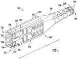
- FIG. 1provides a perspective view of a push-pull boot connector according to one or more exemplary embodiments of the present subject matter.
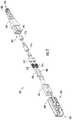
- FIG. 2provides an exploded view of the exemplary push-pull boot connector of FIG. 1 .
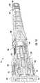
- FIG. 3provides a section view of a push-pull connection according to one or more exemplary embodiments of the present subject matter.
- FIG. 4provides an enlarged view of a portion of FIG. 3 .
- FIG. 5provides a perspective view of a push-pull boot connector according to one or more additional embodiments of the present subject matter.
- FIG. 6provides an exploded view of the exemplary push-pull boot connector of FIG. 5 .
- FIG. 7provides a section view of a push-pull connection according to one or more additional exemplary embodiments of the present subject matter.
- FIG. 8provides an enlarged view of a portion of FIG. 7 with a connector release arm of the push-pull connection in a latched position.
- FIG. 9provides an enlarged view of a portion of FIG. 7 with a connector release arm of the push-pull connection in a release position.
- FIG. 10provides a perspective view of a push-pull boot connector according to one or more additional embodiments of the present subject matter.
- FIG. 11provides an exploded view of the exemplary push-pull boot connector of FIG. 10 .
- FIG. 12provides a section view of a push-pull connection according to one or more additional exemplary embodiments of the present subject matter.
- FIG. 13provides an enlarged view of a portion of FIG. 12 .
- FIG. 14provides a perspective view of a push-pull boot connector according to one or more additional embodiments of the present subject matter.
- FIG. 15provides an exploded view of the exemplary push-pull boot connector of FIG. 14 .
- FIG. 16provides a section view of a push-pull connection according to one or more additional exemplary embodiments of the present subject matter.
- FIG. 17provides an enlarged view of a portion of FIG. 16 .
- terms of approximationsuch as “generally,” “about,” or “approximately” include values within ten percent greater or less than the stated value.
- such termsinclude within ten degrees greater or less than the stated angle or direction, e.g., “generally vertical” includes forming an angle of up to ten degrees in any direction, e.g., clockwise or counterclockwise, with the vertical direction.
- FIG. 1illustrates a push-pull boot connector 100 according to one exemplary embodiment of the present disclosure.
- FIG. 2provides an exploded view of the push-pull connector 100 of FIG. 1 .
- the push-pull boot connector 100is a duplex uniboot connector, e.g., the push-pull boot connector 100 includes two ferrules 208 and a single strain relief boot 300 .
- the push-pull boot connector 100extends along a longitudinal direction L from a proximal end 102 to a distal end 104 .
- the push-pull boot connector 100includes a connector housing 200 defining the proximal end 102 of the push-pull boot connector 100 at a first end 202 of the housing 200 .
- a second end 204 of the connector housing 200is connected to a first end 302 of the strain relief boot 300 and a second end 304 of the strain relief boot 300 defines the distal end 104 of the push-pull connector 100 .
- pulling on the boot 300allows the release of the connector 100 from the adapter 400 (see, e.g., FIGS. 3 and 4 ).
- the connector 100may be a remote release connector and accessibility to release the connector 100 may thereby be improved.
- the strain relief boot 300may include features to promote ease of manipulating the strain relief boot 300 , e.g., for assisting a user in gripping the strain relief boot 300 to push the push-pull boot connector 100 into a connection and/or to pull the push-pull boot connector 100 out of a connection such as when installing or removing the connector in a hub such as a main distribution frame.
- such featuresmay include one or more ridges 308 at or proximate to the second end 304 of the strain relief boot 300 which provide a profiled edge to assist in gripping the push-pull boot connector 100 , e.g., with a user's fingers, at the second end 304 of the strain relief boot 300 , which, as noted above, defines the distal end 104 of the push-pull boot connector 100 .
- the push-pull boot connector 100may be a remote release push-pull boot connector, e.g., in that the user does not need access to the proximal end 102 of the push-pull boot connector 100 . Rather, the remote release connector 100 can be released by manipulating the strain relief boot 300 , which is remote, e.g., distal, from the point of connection at the proximal end 102 of the push-pull boot connector 100 .
- the push-pull connector 100includes a ferrule holder 206 which fits within the connector housing 200 .
- One or more ferrules 208may be positioned in the ferrule holder 206 of the connector housing 200 .
- the ferrules 208are each configured for supporting and aligning an optical fiber (not shown) in order to promote an optical connection of the optical fibers in the ferrules 206 with, e.g., a receptacle in a main distribution frame.
- the ferrules 208may be biased forward, e.g., towards the proximal end 102 of the push-pull boot connector 100 , by a pair of springs 210 , each spring 210 of the pair of springs 210 corresponding to one of the ferrules 208 .
- the connector housing 200may further include various internal components for supporting and/or aligning the ferrules 208 and any optical fibers therein, as well as for mounting the push-pull boot connector 100 on a cable containing the optical fibers.
- internal componentsmay include a bracket 212 , a first collar 214 and a second collar 216 .
- the bracket 212may be positioned immediately distal of the ferrules 208 and/or the springs 210 , e.g., when the internal components are installed within the connector housing 200 , such that the springs 210 may bias against the bracket 212 at one end of the springs 210 and against a flange on each respective ferrule 208 at the other end of the springs 210 .
- the collars 214 and 216may be configured to receive an open end of a cable containing the optical fibers which are received in the ferrules 208 and secure the open end of the cable within the push-pull boot connector 100 .
- the connector housing 200is connected to the strain relief boot 300 .
- Such connectionmay be a clip-in connection, where the connector housing 200 is connected to the strain relief boot 300 by a clip on one of the strain relief boot 300 and the connector housing 200 , and the clip is engaged with a clip mating face on the other of the strain relief boot 300 and the connector housing 200 .
- the strain relief boot 300may include one or more mating clips 306 ( FIG. 2 ) which are engageable with corresponding clip mating face(s) 218 ( FIG. 1 ) of the connector housing 200 . When connected by such a clip-in connection, the connector housing 200 and the strain relief boot 300 may thereby be free to move together along the longitudinal direction L.
- an example push-pull connection 10includes the push-pull boot connector 100 and an adapter 400 .
- the push-pull boot connector 100also includes a latch release ramp 106 on one of the connector housing 200 and the strain relief boot 300 .
- the latch release ramp 106is positioned on the connector housing 200 .
- the adapter 400includes a channel 406 configured to receive the proximal end 102 of the push-pull boot connector 100 and a latch 408 positioned in the channel 406 of the adapter 400 to engage the push-pull boot connector 100 when the push-pull boot connector 100 moves relative to the adapter 400 in a first direction 1000 along the longitudinal direction L, e.g., into the channel 406 of the adapter 400 .
- the adapter 400is a dual latch adapter with a pair of opposing latches 408 . As shown in FIGS.
- the pair of latches 408are disposed at opposite sides of the channel 406 , e.g., a first latch 408 is disposed at the top of the channel 406 and a second latch 408 is disposed at the bottom of the channel 406 , e.g., when the push-pull connection 10 is positioned as shown in FIG. 3 .
- the latches 408may be mirror images of one another, e.g., each latch 408 may extend into the channel 406 from one of the opposing sides towards the other latch 408 .
- the latches 408may each engage with a recess or notch 220 in the connector housing 200 ( FIGS. 1 and 4 ).
- the latches 408Through engagement of the latches 408 with the push-pull boot connector 100 , the latches 408 retain the push-pull boot connector 100 in the channel 406 of the adapter 400 when the push-pull boot connector 100 is inserted, e.g., pushed, into the channel 406 of the adapter 400 .
- the push-pull boot connector 100may include a pair of latch release ramps 106 corresponding to the pair of opposing latches 408 .
- each latch release ramp 106 of the pair of latch release ramps 106may be configured to disengage a corresponding latch 408 of the pair of opposing latches 408 from the push-pull boot connector 100 when the push-pull boot connector 100 moves in the second direction 2000 relative to the adapter 400 , e.g., when the push-pull boot connector 100 is pulled out of the adapter 400 .
- the latch release ramp 106 of the push-pull boot connector 100may be configured to disengage the latch 408 of the adapter 400 from the push-pull boot connector 100 when the push-pull boot connector 100 moves relative to the adapter 400 in the second direction 2000 .
- the latch release ramp 106may be oblique to the longitudinal direction L and may slope towards the distal end 104 of the push-pull boot connector 100 .
- the latch release ramp 106may extend from a high point at a proximal end of the latch release ramp 106 , the proximal end of the latch release ramp 106 being, e.g., an end of the latch release ramp 106 which is closer to or oriented towards the proximal end 102 of the push-pull boot connector 100 , to a low point at a distal end of the latch release ramp 106 , the distal end of the latch release ramp 106 being, e.g., an end of the latch release ramp 106 which is closer to or oriented towards the distal end 104 of the push-pull boot connector 100 .
- the latch release ramp 106may be generally oriented or sloped opposite the latch 408 , in order to disengage the latch 408 of the adapter 400 from the push-pull boot connector 100 when the push-pull boot connector 100 moves relative to the adapter 400 in the second direction 2000 , e.g., when the push-pull boot connector 100 is pulled out of the adapter 400 .
- FIGS. 5-9illustrate an additional embodiment of the present subject matter, where the push-pull boot connector 100 is a duplex uniboot connector.
- the push-pull boot connector 100may include a collar 214 which serves as a crimp for a jacket or strength member of a fiber optic cable.
- the latch 408may be a single latch. As shown, the latch 408 also may be provided as a leaf spring within the channel 406 . The leaf spring latch 408 of FIGS.
- 7-9may be provided as a single latch 408 , as shown, or may be provided as a dual latch in other embodiments, e.g., one or more of the dual latches 408 shown in FIGS. 3, 4, 12, 13, 16 , and/or 17 may also be provided as leaf spring latches 408 .
- the latch release ramp 106is positioned on the strain relief boot 300 .
- the latch release ramp 106is positioned on a connector release arm 310 of the strain relief boot 300 .
- the push-pull boot connector 100may include a spring 210 positioned generally between the connector housing 200 and the strain relief boot 300 , such as between the connector release arm 310 of the strain relief boot 300 and a shoulder 222 on the connector housing 200 , e.g., as shown in FIGS. 7-9 .
- the spring 210may be configured to bias the connector release arm 310 in the first direction 1000 . As most easily seen in FIGS.
- the connector release arm 310may be configured to move a fixed distance relative to the connector housing 200 in the second direction 2000 .
- the connector release arm 310may be biased to or towards a latched position, as shown, e.g., in FIGS. 5 and 8 , by the spring 210 .
- the connector release arm 310may move the fixed distance from the latched position of FIG. 8 to a release position, which is shown in FIG. 9 .
- the fixed distancemay be defined by the shoulder 222 on the connector housing 200 , where the connector release arm 310 abuts the shoulder 222 when in the release position, as shown in FIG. 9 .
- the connector housing 200 and the strain relief boot 300may move together in the second direction 2000 , e.g., as the push-pull boot connector 100 is pulled out of the adapter 400 .
- the spring 210may be configured to return the connector release arm 310 in the first direction 1000 to the latched position from the release position. As shown in FIG.
- the latch release ramp 106biases the latch 408 outward, e.g., away from the push-pull boot connector 100 , to disengage the latch 408 from the push-pull boot connector 100 .
- the push-pull boot connector 100may be a SC duplex uniboot connector.
- the latch release ramp 106may be provided on the connector housing 200 of the push-pull boot connector 100 .
- the latch release ramp 106may be provided proximate the first end 202 of the connector housing 200 and close to the portion of the connector housing 200 in which the ferrule holders 206 are received. As shown in FIG.
- the push-pull boot connector 100may include two ferrules 208 and two corresponding ferrule holders 206 , with the ferrules 208 biased forward, e.g., to or towards the proximal end 102 of the push-pull boot connector 100 , by springs 210 positioned between a flange on each ferrule 208 and a first collar 214 .
- the push-pull boot connector 100may further include a bracket 212 distal of the first collar 214 and a second collar 216 distal of the bracket 212 .
- One or both of the collars 214 and 216may be configured to engage and support an end of a fiber optic cable containing the optical fibers which are routed through the ferrules 208 .
- the latch release ramp 106biases the latch 408 outward, e.g., away from the push-pull boot connector 100 along a third direction 3000 which is generally perpendicular to the longitudinal direction L, to disengage the latch 408 from the push-pull boot connector 100 .
- the push-pull boot connector 100may also be a SC simplex connector, e.g., including a single ferrule 208 for a single optical fiber, as illustrated in FIGS. 14-17 .
- the latch release ramp 106may be provided on the connector housing 200 of the push-pull boot connector 100 .
- the latch release ramp 106may be provided proximate the first end 202 of the connector housing 200 and close to the portion of the connector housing 200 in which the ferrule holders 206 are received.
- the present subject matterprovides numerous advantages over the prior art, as will be apparent to those of ordinary skill. For example, utilization of an industry standard recognized connector design that has a dual latching feature that does not protrude beyond the body of the connector, therefore minimizing the space required for the connection to occur. This in turn allows a greater density to be mounted within a standard footprint of one rack unit (1RU). The density of a 1RU panel can be increased, e.g., up to 288 fibers. As another example, the combination of a connector variant with a uniboot design minimizes cable volume as compared to a design including more than one boot.
- Ease of access to install or remove the push-pull boot connector 100is increased, e.g., in that the installation or removal can be performed by pushing or pulling on the connector boot 300 instead of needing access to the connector housing 200 .
- No remote pulling latch to hinder cable routing or finger accessis included.
Landscapes
- Physics & Mathematics (AREA)
- General Physics & Mathematics (AREA)
- Optics & Photonics (AREA)
- Mechanical Coupling Of Light Guides (AREA)
- Details Of Connecting Devices For Male And Female Coupling (AREA)
Abstract
Description
Claims (18)
Priority Applications (11)
| Application Number | Priority Date | Filing Date | Title |
|---|---|---|---|
| US16/056,907US10634854B2 (en) | 2018-01-03 | 2018-08-07 | Push-pull boot connector for fiber optic cables |
| EP19701743.7AEP3735604B1 (en) | 2018-01-03 | 2019-01-02 | Push-pull boot connector for fiber optic cables |
| JP2020537239AJP2021509735A (en) | 2018-01-03 | 2019-01-02 | Push-pull boot connector for fiber optic cables |
| MX2020006725AMX2020006725A (en) | 2018-01-03 | 2019-01-02 | Push-pull boot connector for fiber optic cables. |
| CA3087633ACA3087633A1 (en) | 2018-01-03 | 2019-01-02 | Push-pull boot connector for fiber optic cables |
| AU2019205186AAU2019205186A1 (en) | 2018-01-03 | 2019-01-02 | Push-pull boot connector for fiber optic cables |
| PCT/US2019/012026WO2019136047A1 (en) | 2018-01-03 | 2019-01-02 | Push-pull boot connector for fiber optic cables |
| EP25177653.0AEP4597185A3 (en) | 2018-01-03 | 2019-01-02 | Push-pull boot connector for fiber optic cables |
| US16/701,886US11169333B2 (en) | 2018-01-03 | 2019-12-03 | Push-pull boot connector for fiber optic cables |
| US16/900,132US11320602B2 (en) | 2018-01-03 | 2020-06-12 | Push-pull boot connector for fiber optic cables |
| US17/715,148US12242117B2 (en) | 2018-01-03 | 2022-04-07 | Push-pull boot connector for fiber optic cables |
Applications Claiming Priority (3)
| Application Number | Priority Date | Filing Date | Title |
|---|---|---|---|
| US201862613266P | 2018-01-03 | 2018-01-03 | |
| US201862640914P | 2018-03-09 | 2018-03-09 | |
| US16/056,907US10634854B2 (en) | 2018-01-03 | 2018-08-07 | Push-pull boot connector for fiber optic cables |
Related Child Applications (1)
| Application Number | Title | Priority Date | Filing Date |
|---|---|---|---|
| US16/701,886ContinuationUS11169333B2 (en) | 2018-01-03 | 2019-12-03 | Push-pull boot connector for fiber optic cables |
Publications (2)
| Publication Number | Publication Date |
|---|---|
| US20190204513A1 US20190204513A1 (en) | 2019-07-04 |
| US10634854B2true US10634854B2 (en) | 2020-04-28 |
Family
ID=67058178
Family Applications (4)
| Application Number | Title | Priority Date | Filing Date |
|---|---|---|---|
| US16/056,907ActiveUS10634854B2 (en) | 2018-01-03 | 2018-08-07 | Push-pull boot connector for fiber optic cables |
| US16/701,886ActiveUS11169333B2 (en) | 2018-01-03 | 2019-12-03 | Push-pull boot connector for fiber optic cables |
| US16/900,132ActiveUS11320602B2 (en) | 2018-01-03 | 2020-06-12 | Push-pull boot connector for fiber optic cables |
| US17/715,148Active2039-09-17US12242117B2 (en) | 2018-01-03 | 2022-04-07 | Push-pull boot connector for fiber optic cables |
Family Applications After (3)
| Application Number | Title | Priority Date | Filing Date |
|---|---|---|---|
| US16/701,886ActiveUS11169333B2 (en) | 2018-01-03 | 2019-12-03 | Push-pull boot connector for fiber optic cables |
| US16/900,132ActiveUS11320602B2 (en) | 2018-01-03 | 2020-06-12 | Push-pull boot connector for fiber optic cables |
| US17/715,148Active2039-09-17US12242117B2 (en) | 2018-01-03 | 2022-04-07 | Push-pull boot connector for fiber optic cables |
Country Status (7)
| Country | Link |
|---|---|
| US (4) | US10634854B2 (en) |
| EP (2) | EP3735604B1 (en) |
| JP (1) | JP2021509735A (en) |
| AU (1) | AU2019205186A1 (en) |
| CA (1) | CA3087633A1 (en) |
| MX (1) | MX2020006725A (en) |
| WO (1) | WO2019136047A1 (en) |
Cited By (4)
| Publication number | Priority date | Publication date | Assignee | Title |
|---|---|---|---|---|
| US11194101B2 (en)* | 2018-09-11 | 2021-12-07 | Senko Advanced Components, Inc. | LC one piece front loaded ferrule with unitary retainer and ferrule holder |
| US20230020676A1 (en)* | 2020-02-14 | 2023-01-19 | Senko Advanced Components, Inc. | Field terminated fiber optic connector |
| US11592627B2 (en) | 2018-04-06 | 2023-02-28 | Us Conec Ltd. | Flexible push-pull boot |
| US11934017B2 (en) | 2021-03-02 | 2024-03-19 | Corning Research & Development Corporation | Polarity changeable optical connector |
Families Citing this family (27)
| Publication number | Priority date | Publication date | Assignee | Title |
|---|---|---|---|---|
| US9658409B2 (en) | 2015-03-03 | 2017-05-23 | Senko Advanced Components, Inc. | Optical fiber connector with changeable polarity |
| US10158194B2 (en) | 2016-01-15 | 2018-12-18 | Senko Advanced Components, Inc. | Narrow width adapters and connectors with spring loaded remote release |
| US9726830B1 (en) | 2016-06-28 | 2017-08-08 | Senko Advanced Components, Inc. | Connector and adapter system for two-fiber mechanical transfer type ferrule |
| US10228521B2 (en) | 2016-12-05 | 2019-03-12 | Senko Advanced Components, Inc. | Narrow width adapters and connectors with modular latching arm |
| US10281669B2 (en) | 2017-07-14 | 2019-05-07 | Senko Advance Components, Inc. | Ultra-small form factor optical connectors |
| US12001064B2 (en) | 2017-07-14 | 2024-06-04 | Senko Advanced Components, Inc. | Small form factor fiber optic connector with multi-purpose boot |
| US10718911B2 (en) | 2017-08-24 | 2020-07-21 | Senko Advanced Components, Inc. | Ultra-small form factor optical connectors using a push-pull boot receptacle release |
| US11822133B2 (en) | 2017-07-14 | 2023-11-21 | Senko Advanced Components, Inc. | Ultra-small form factor optical connector and adapter |
| US11002923B2 (en) | 2017-11-21 | 2021-05-11 | Senko Advanced Components, Inc. | Fiber optic connector with cable boot release having a two-piece clip assembly |
| US11016250B2 (en)* | 2017-12-19 | 2021-05-25 | Us Conec, Ltd. | Mini duplex connector with push-pull polarity mechanism, carrier, and rail-receiving crimp body |
| US10634854B2 (en)* | 2018-01-03 | 2020-04-28 | Afl Ig Llc | Push-pull boot connector for fiber optic cables |
| EP3776038B1 (en) | 2018-03-28 | 2024-07-03 | Senko Advanced Components Inc. | Small form factor fiber optic connector with multi-purpose boot |
| EP3781970B1 (en)* | 2018-04-17 | 2023-11-15 | Senko Advanced Components Inc. | Fiber optic receptacle with an integrated engagement device therein |
| CN112088327A (en)* | 2018-07-15 | 2020-12-15 | 扇港元器件股份有限公司 | Subminiature Optical Connectors and Adapters |
| US11073664B2 (en) | 2018-08-13 | 2021-07-27 | Senko Advanced Components, Inc. | Cable boot assembly for releasing fiber optic connector from a receptacle |
| US10921530B2 (en) | 2018-09-12 | 2021-02-16 | Senko Advanced Components, Inc. | LC type connector with push/pull assembly for releasing connector from a receptacle using a cable boot |
| WO2020086184A1 (en)* | 2018-09-12 | 2020-04-30 | Senko Advanced Components, Inc | Lc type connector with push/pull assembly for releasing connector from a receptacle using a cable boot |
| WO2020055440A1 (en) | 2018-09-12 | 2020-03-19 | Senko Advanced Componetns, Inc. | Lc type connector with clip-on push/pull tab for releasing connector from a receptacle using a cable boot |
| US10921531B2 (en) | 2018-09-12 | 2021-02-16 | Senko Advanced Components, Inc. | LC type connector with push/pull assembly for releasing connector from a receptacle using a cable boot |
| CN113296198A (en)* | 2020-02-21 | 2021-08-24 | 佑胜光电股份有限公司 | Optical transmission assembly, optical transceiver module and optical fiber cable module |
| US11340406B2 (en) | 2019-04-19 | 2022-05-24 | Senko Advanced Components, Inc. | Small form factor fiber optic connector with resilient latching mechanism for securing within a hook-less receptacle |
| US11397298B2 (en)* | 2019-05-30 | 2022-07-26 | Us Conec, Ltd. | Adapter to jacketed fiber interface |
| WO2020252355A1 (en) | 2019-06-13 | 2020-12-17 | Senko Advanced Components, Inc | Lever actuated latch arm for releasing a fiber optic connector from a receptacle port and method of use |
| CN114600018B (en) | 2019-07-23 | 2024-04-09 | 扇港元器件有限公司 | Ultra-small receptacle for receiving a fiber optic connector opposite a ferrule assembly |
| US10845542B1 (en) | 2019-08-19 | 2020-11-24 | Afl Telecommunications Llc | Cable node transition assemblies |
| US11650379B2 (en)* | 2020-10-14 | 2023-05-16 | Us Conec Ltd. | Anti-buckling latch for a fiber optic connector |
| USD1031670S1 (en)* | 2021-11-08 | 2024-06-18 | Us Conec Ltd. | Self-locking boot latch |
Citations (9)
| Publication number | Priority date | Publication date | Assignee | Title |
|---|---|---|---|---|
| US5321784A (en)* | 1993-02-18 | 1994-06-14 | Minnesota Mining And Manufacturing Company | Pull-proof, modular fiber optic connector system |
| US20070190834A1 (en) | 2006-02-14 | 2007-08-16 | Japan Aviation Electronics Industry, Limited | Optical connector apparatus suitable for interconnection between different-diameter ferrules |
| US20140205257A1 (en)* | 2012-05-21 | 2014-07-24 | Advanced Fiber Products, LLC | Secure SC Optical Fiber Connector and Removal Tools |
| WO2015103783A1 (en) | 2014-01-13 | 2015-07-16 | Tyco Electronics (Shanghai) Co., Ltd. | Fiber optic connector |
| US20160154190A1 (en) | 2014-01-28 | 2016-06-02 | Jyh Eng Technology Co., Ltd. | Duplex fiber optic connector plug |
| US20160231512A1 (en)* | 2013-11-08 | 2016-08-11 | Honda Tsushin Kogyo Co., Ltd. | Optical connector plug |
| WO2017123264A1 (en) | 2016-01-15 | 2017-07-20 | Senko Advanced Components, Inc. | Narrow width adapters and connectors with spring loaded remote release |
| US20170276275A1 (en)* | 2014-10-23 | 2017-09-28 | Idex Health & Science Llc | Fluidic Connector Assembly for Quick Connect/Disconnect |
| US20170307831A1 (en) | 2014-12-24 | 2017-10-26 | Japan Aviation Electronics Industry, Limited | Connector-equipped plug |
Family Cites Families (12)
| Publication number | Priority date | Publication date | Assignee | Title |
|---|---|---|---|---|
| US6811445B2 (en)* | 2002-04-22 | 2004-11-02 | Panduit Corp. | Modular cable termination plug |
| US7762726B2 (en)* | 2007-12-11 | 2010-07-27 | Adc Telecommunications, Inc. | Hardened fiber optic connection system |
| US8172468B2 (en)* | 2010-05-06 | 2012-05-08 | Corning Incorporated | Radio frequency identification (RFID) in communication connections, including fiber optic components |
| US8764308B2 (en)* | 2011-06-06 | 2014-07-01 | Panduit Corp. | Duplex clip assembly for fiber optic connectors |
| US9429732B2 (en)* | 2013-05-03 | 2016-08-30 | Corning Cable Systems Llc | Fiber optic cable crimp assemblies employing integrally connected cable strain relief boots, and related fiber optic connectors, cables, and methods |
| JP6400892B2 (en)* | 2013-09-17 | 2018-10-03 | 三和電気工業株式会社 | LC type optical connector adapter with built-in dustproof shutter |
| US9207410B2 (en)* | 2013-12-23 | 2015-12-08 | Alliance Fiber Optic Products, Inc. | Optical fiber connector assembly |
| EP3158375A1 (en)* | 2014-06-23 | 2017-04-26 | Tyco Electronics Raychem BVBA | Fiber optic connection system with fast coupling mechanism |
| US9599778B2 (en)* | 2014-10-22 | 2017-03-21 | Senko Advanced Components, Inc. | Latching connector with remote release |
| WO2017046062A1 (en)* | 2015-09-14 | 2017-03-23 | CommScope Connectivity Belgium BVBA | Ferrule housing with integrated boot |
| WO2019055820A1 (en)* | 2017-09-15 | 2019-03-21 | Commscope Technologies Llc | Fiber optic connector with boot-integrated release and related assemblies |
| US10634854B2 (en)* | 2018-01-03 | 2020-04-28 | Afl Ig Llc | Push-pull boot connector for fiber optic cables |
- 2018
- 2018-08-07USUS16/056,907patent/US10634854B2/enactiveActive
- 2019
- 2019-01-02JPJP2020537239Apatent/JP2021509735A/enactivePending
- 2019-01-02CACA3087633Apatent/CA3087633A1/enactivePending
- 2019-01-02AUAU2019205186Apatent/AU2019205186A1/ennot_activeAbandoned
- 2019-01-02EPEP19701743.7Apatent/EP3735604B1/enactiveActive
- 2019-01-02MXMX2020006725Apatent/MX2020006725A/enunknown
- 2019-01-02WOPCT/US2019/012026patent/WO2019136047A1/ennot_activeCeased
- 2019-01-02EPEP25177653.0Apatent/EP4597185A3/enactivePending
- 2019-12-03USUS16/701,886patent/US11169333B2/enactiveActive
- 2020
- 2020-06-12USUS16/900,132patent/US11320602B2/enactiveActive
- 2022
- 2022-04-07USUS17/715,148patent/US12242117B2/enactiveActive
Patent Citations (9)
| Publication number | Priority date | Publication date | Assignee | Title |
|---|---|---|---|---|
| US5321784A (en)* | 1993-02-18 | 1994-06-14 | Minnesota Mining And Manufacturing Company | Pull-proof, modular fiber optic connector system |
| US20070190834A1 (en) | 2006-02-14 | 2007-08-16 | Japan Aviation Electronics Industry, Limited | Optical connector apparatus suitable for interconnection between different-diameter ferrules |
| US20140205257A1 (en)* | 2012-05-21 | 2014-07-24 | Advanced Fiber Products, LLC | Secure SC Optical Fiber Connector and Removal Tools |
| US20160231512A1 (en)* | 2013-11-08 | 2016-08-11 | Honda Tsushin Kogyo Co., Ltd. | Optical connector plug |
| WO2015103783A1 (en) | 2014-01-13 | 2015-07-16 | Tyco Electronics (Shanghai) Co., Ltd. | Fiber optic connector |
| US20160154190A1 (en) | 2014-01-28 | 2016-06-02 | Jyh Eng Technology Co., Ltd. | Duplex fiber optic connector plug |
| US20170276275A1 (en)* | 2014-10-23 | 2017-09-28 | Idex Health & Science Llc | Fluidic Connector Assembly for Quick Connect/Disconnect |
| US20170307831A1 (en) | 2014-12-24 | 2017-10-26 | Japan Aviation Electronics Industry, Limited | Connector-equipped plug |
| WO2017123264A1 (en) | 2016-01-15 | 2017-07-20 | Senko Advanced Components, Inc. | Narrow width adapters and connectors with spring loaded remote release |
Non-Patent Citations (1)
| Title |
|---|
| AFL Telecommunications LLC; International Patent Application No. PCT/US2019/012026; International Search Report; dated Apr. 29, 2019; (2 pages). |
Cited By (9)
| Publication number | Priority date | Publication date | Assignee | Title |
|---|---|---|---|---|
| US11592627B2 (en) | 2018-04-06 | 2023-02-28 | Us Conec Ltd. | Flexible push-pull boot |
| US11719893B2 (en) | 2018-04-06 | 2023-08-08 | Us Conec Ltd. | Flexible push-pull boot and crimp body for fiber optic connector |
| US11906794B2 (en) | 2018-04-06 | 2024-02-20 | Us Conec Ltd. | Flexible push-pull boot and crimp body for fiber optic connector |
| US12013580B2 (en) | 2018-04-06 | 2024-06-18 | Us Conec Ltd. | Flexible push-pull boot |
| US12399330B2 (en) | 2018-04-06 | 2025-08-26 | Us Conec Ltd. | Flexible push-pull boot |
| US11194101B2 (en)* | 2018-09-11 | 2021-12-07 | Senko Advanced Components, Inc. | LC one piece front loaded ferrule with unitary retainer and ferrule holder |
| US20230020676A1 (en)* | 2020-02-14 | 2023-01-19 | Senko Advanced Components, Inc. | Field terminated fiber optic connector |
| US12158620B2 (en)* | 2020-02-14 | 2024-12-03 | Senko Advanced Components, Inc. | Field terminated fiber optic connector |
| US11934017B2 (en) | 2021-03-02 | 2024-03-19 | Corning Research & Development Corporation | Polarity changeable optical connector |
Also Published As
| Publication number | Publication date |
|---|---|
| MX2020006725A (en) | 2020-10-01 |
| JP2021509735A (en) | 2021-04-01 |
| US20200103598A1 (en) | 2020-04-02 |
| US20220229241A1 (en) | 2022-07-21 |
| US12242117B2 (en) | 2025-03-04 |
| EP3735604B1 (en) | 2025-07-02 |
| EP4597185A2 (en) | 2025-08-06 |
| US11320602B2 (en) | 2022-05-03 |
| WO2019136047A1 (en) | 2019-07-11 |
| CA3087633A1 (en) | 2019-07-11 |
| EP3735604A1 (en) | 2020-11-11 |
| US20190204513A1 (en) | 2019-07-04 |
| US11169333B2 (en) | 2021-11-09 |
| US20200310042A1 (en) | 2020-10-01 |
| AU2019205186A1 (en) | 2020-08-20 |
| EP4597185A3 (en) | 2025-10-08 |
Similar Documents
| Publication | Publication Date | Title |
|---|---|---|
| US12242117B2 (en) | Push-pull boot connector for fiber optic cables | |
| US10877226B2 (en) | Remote release tab connector assembly | |
| US9261653B2 (en) | Fiber optic plug assembly and optical connector system | |
| US10359583B2 (en) | Behind the wall optical connector with reduced components | |
| US11500164B2 (en) | LC type connector with push/pull assembly for releasing connector from a receptacle using a cable boot | |
| CN101494331B (en) | Connector assembly having a movable plug | |
| US10921530B2 (en) | LC type connector with push/pull assembly for releasing connector from a receptacle using a cable boot | |
| US11320605B2 (en) | MPO microlatch lock connector | |
| US12038613B2 (en) | Behind-the-wall optical connector and assembly of the same | |
| KR20210031788A (en) | Narrow width adapters and connectors with modular latching arm | |
| KR20080094026A (en) | Fiber optic splitter module | |
| US11435535B2 (en) | Behind the wall optical connector with reduced components | |
| US20180259717A1 (en) | Fiber optic receptacle with integrated device therein | |
| CN114026480B (en) | Lever actuated latch arm for releasing fiber optic connectors from receptacle ports and method of use | |
| US11086087B2 (en) | LC type connector with clip-on push/pull tab for releasing connector from a receptacle using a cable boot | |
| TW201833609A (en) | Narrow width adapters and connectors with modular latching arm | |
| CN116635764A (en) | Narrow width optical connector and optical receptacle | |
| WO2020086184A1 (en) | Lc type connector with push/pull assembly for releasing connector from a receptacle using a cable boot |
Legal Events
| Date | Code | Title | Description |
|---|---|---|---|
| AS | Assignment | Owner name:AFL IG LLC, SOUTH CAROLINA Free format text:ASSIGNMENT OF ASSIGNORS INTEREST;ASSIGNORS:DAVIDSON, ARAN JAMES RUSSELL;RAVEN, ASHER LEONG;REEL/FRAME:046571/0442 Effective date:20180802 | |
| FEPP | Fee payment procedure | Free format text:ENTITY STATUS SET TO UNDISCOUNTED (ORIGINAL EVENT CODE: BIG.); ENTITY STATUS OF PATENT OWNER: LARGE ENTITY | |
| STPP | Information on status: patent application and granting procedure in general | Free format text:RESPONSE TO NON-FINAL OFFICE ACTION ENTERED AND FORWARDED TO EXAMINER | |
| STPP | Information on status: patent application and granting procedure in general | Free format text:FINAL REJECTION MAILED | |
| STPP | Information on status: patent application and granting procedure in general | Free format text:RESPONSE AFTER FINAL ACTION FORWARDED TO EXAMINER | |
| STPP | Information on status: patent application and granting procedure in general | Free format text:ADVISORY ACTION MAILED | |
| STPP | Information on status: patent application and granting procedure in general | Free format text:RESPONSE AFTER FINAL ACTION FORWARDED TO EXAMINER | |
| STPP | Information on status: patent application and granting procedure in general | Free format text:DOCKETED NEW CASE - READY FOR EXAMINATION | |
| STPP | Information on status: patent application and granting procedure in general | Free format text:NOTICE OF ALLOWANCE MAILED -- APPLICATION RECEIVED IN OFFICE OF PUBLICATIONS | |
| STCF | Information on status: patent grant | Free format text:PATENTED CASE | |
| MAFP | Maintenance fee payment | Free format text:PAYMENT OF MAINTENANCE FEE, 4TH YEAR, LARGE ENTITY (ORIGINAL EVENT CODE: M1551); ENTITY STATUS OF PATENT OWNER: LARGE ENTITY Year of fee payment:4 | |
| AS | Assignment | Owner name:AFL TELECOMMUNICATIONS LLC, SOUTH CAROLINA Free format text:MERGER;ASSIGNOR:AFL IG LLC;REEL/FRAME:070932/0190 Effective date:20221114 |