US10633955B2 - Nano-particle reinforced well screen - Google Patents
Nano-particle reinforced well screenDownload PDFInfo
- Publication number
- US10633955B2 US10633955B2US14/370,461US201214370461AUS10633955B2US 10633955 B2US10633955 B2US 10633955B2US 201214370461 AUS201214370461 AUS 201214370461AUS 10633955 B2US10633955 B2US 10633955B2
- Authority
- US
- United States
- Prior art keywords
- nano
- filter
- well screen
- particle reinforcement
- ceramic material
- Prior art date
- Legal status (The legal status is an assumption and is not a legal conclusion. Google has not performed a legal analysis and makes no representation as to the accuracy of the status listed.)
- Active, expires
Links
Images


Classifications
- E—FIXED CONSTRUCTIONS
- E21—EARTH OR ROCK DRILLING; MINING
- E21B—EARTH OR ROCK DRILLING; OBTAINING OIL, GAS, WATER, SOLUBLE OR MELTABLE MATERIALS OR A SLURRY OF MINERALS FROM WELLS
- E21B43/00—Methods or apparatus for obtaining oil, gas, water, soluble or meltable materials or a slurry of minerals from wells
- E21B43/02—Subsoil filtering
- E21B43/08—Screens or liners
- E21B43/082—Screens comprising porous materials, e.g. prepacked screens
- E—FIXED CONSTRUCTIONS
- E03—WATER SUPPLY; SEWERAGE
- E03B—INSTALLATIONS OR METHODS FOR OBTAINING, COLLECTING, OR DISTRIBUTING WATER
- E03B3/00—Methods or installations for obtaining or collecting drinking water or tap water
- E03B3/06—Methods or installations for obtaining or collecting drinking water or tap water from underground
- E03B3/08—Obtaining and confining water by means of wells
- E03B3/16—Component parts of wells
- E03B3/18—Well filters
- E03B3/20—Well filters of elements of special shape
- E—FIXED CONSTRUCTIONS
- E21—EARTH OR ROCK DRILLING; MINING
- E21B—EARTH OR ROCK DRILLING; OBTAINING OIL, GAS, WATER, SOLUBLE OR MELTABLE MATERIALS OR A SLURRY OF MINERALS FROM WELLS
- E21B43/00—Methods or apparatus for obtaining oil, gas, water, soluble or meltable materials or a slurry of minerals from wells
- E21B43/02—Subsoil filtering
- E21B43/08—Screens or liners
Definitions
- This disclosurerelates generally to equipment utilized and operations performed in conjunction with a subterranean well and, in one example described below, more particularly provides a well screen with a nano-particle reinforced filter.
- Well screensare used to filter fluid produced from earth formations. Well screens remove sand, fines, debris, etc., from the fluid. It will be appreciated that improvements are continually needed in the art of constructing well screens.
- the well screencan include a filter with a nano-particle reinforcement.
- a method of constructing a well screenis also described below.
- the methodcan include treating a filter with a nano-particle reinforcement.
- the filtermay comprise a porous substrate.
- the porous substratecan comprise a ceramic material.
- the nano-particle reinforcementmay be disposed in pores of the ceramic material.
- the nano-particle reinforcementcan comprise nano-fibers, or other types of nano-particles.
- the nano-particle reinforcementmay increase a tensile strength of the filter, reduce a brittleness of the filter, and/or increase an erosion resistance of the filter.
- the filtermay comprise a ceramic material which filters fluid which flows between an annulus external to the well screen and an interior flow passage of the well screen.
- the filtermay comprise a porous substrate positioned radially between a base pipe and a protective shroud.
- FIG. 1is a representative partially cross-sectional view of a well system and associated method which can embody principles of this disclosure.
- FIG. 2is a representative oblique view of a filter for a well screen which may be used in the system and method of FIG. 1 , and which can embody principles of this disclosure.
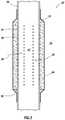
- FIG. 3is a representative cross-sectional view of the well screen.
- FIG. 1Representatively illustrated in FIG. 1 is a system 10 for use with a subterranean well, and an associated method, which system and method can embody principles of this disclosure.
- system 10 and methodare merely one example of an application of the principles of this disclosure in practice, and a wide variety of other examples are possible. Therefore, the scope of this disclosure is not limited at all to the details of the system 10 and method described herein and/or depicted in the drawings.
- a tubular string 12(such as a production tubing string, a testing work string, a completion string, a gravel packing and/or stimulation string, etc.) is installed in a wellbore 14 lined with casing 16 and cement 18 .
- the tubular string 12 in this exampleincludes a packer 20 and a well screen 22 .
- the packer 20isolates a portion of an annulus 24 formed radially between the tubular string 12 and the wellbore 14 .
- the well screen 22filters fluid 26 which flows into the tubular string 12 from the annulus 24 (and from an earth formation 28 into the annulus).
- the well screen 22 in this exampleincludes end connections 29 (such as internally or externally formed threads, seals, etc.) for interconnecting the well screen in the tubular string 12 .
- the tubular string 12may be continuous or segmented, and made of metal and/or nonmetal material.
- the tubular string 12does not necessarily include the packer 20 or any other particular item(s) of equipment. Indeed, the tubular string 12 is not even necessary in keeping with the principles of this disclosure.
- Examples of the well screen 22are described in more detail below. Each of the examples described below can be constructed conveniently, rapidly and economically, thereby improving a cost efficiency of the well system 10 and method, while effectively filtering the fluid 26 .
- a generally tubular filter 30 of the well screen 22is representatively illustrated.
- the filter 30is depicted in FIG. 2 as having an annular shape, and being a single element, any shape or number of elements may be used in the filter.
- the filtercould be sectioned radially and/or longitudinally, the filter could be flat or made up of flat elements, etc.
- the filter 30comprises a porous substrate 32 reinforced with a nano-particle reinforcement 34 .
- the porous substrate 32can comprise a ceramic material 36 .
- the nano-particle reinforcement 34 in this examplecan be dispersed into pores of the ceramic material 36 .
- the filtercan obtain increased strength, reduced brittleness, and/or reduced erosion due to flow of the fluid 26 through the filter.
- the reduced brittlenesscan be especially beneficial if the filter 30 comprises the ceramic material 36 , or any relatively brittle material.
- Suitable ceramic materials for use in the filter 30include silicon carbide, alumina and mullite. Other materials and non-ceramic materials may be used, if desired.
- Suitable nano-particle reinforcement 34 materialsinclude titanium nitride, chromium nitride, silica, diamond, aluminum oxide, titanium oxide, etc.
- Suitable types of nano-particlesinclude carbon nano-tubes and nano-graphites, nano-clusters, nano-powders, etc.
- a nano-particleis generally understood to have at least one dimension from 100 to 1 nanometers.
- nano-particle reinforcementrefers to a reinforcement comprising particles having at least one dimension which is from about 1 nanometer to about 100 nanometers.
- FIG. 3a cross-sectional view of one example of the well screen 22 is representatively illustrated.
- the filter 30is positioned radially between a base pipe 38 and a protective shroud 40 .
- the base pipe 38can have the end connections 29 for connecting the well screen 22 in the tubular string 12 in the system 10 of FIG. 1 .
- a longitudinal flow passage 42 of the tubular string 12can extend through the base pipe 38 .
- the well screen 22could be used in other systems and methods, in keeping with the scope of this disclosure.
- the filter 30is depicted in FIG. 3 as being external to the base pipe 38 , but in other examples the filter 30 could be otherwise positioned relative to the base pipe (such as, internal to the base pipe, etc.).
- the substrate 32can be separately formed (e.g., by casting, molding, etc.), and then positioned on or in, etc. the base pipe 38 .
- the substrate 32could be formed on or in the base pipe 38 (e.g., by casting or molding the substrate on or in the base pipe, etc.).
- the substrate 32may be treated with the nano-particle reinforcement 34 prior to, during or after the substrate is positioned relative to the base pipe 38 .
- the substrate 32may be treated with the nano-particle reinforcement 34 by spraying or coating the substrate with nano-particles, molding or casting the substrate with the nano-particles, applying the nano-particles to the substrate, mixing the nano-particles with the substrate, etc. Any manner of incorporating the nano-particle reinforcement 34 into the filter 30 may be used, in keeping with the scope of this disclosure.
- the filter 30can be produced by treating a ceramic substrate 32 with a nano-particle reinforcement 34 .
- a nano-particle reinforcement 34For example, carbon nano-tubes or nano-graphites could increase the tensile strength of the filter 30 , increase the filter's erosion resistance, and reduce the ceramic substrate's brittleness.
- the shroud 40is depicted in FIG. 3 as outwardly enclosing the filter 30 . In this manner, the shroud 40 can protect the filter 30 during installation of the tubular string 12 in the wellbore 14 . However, if the filter 30 is otherwise positioned (e.g., not external to the base pipe 38 ), then the shroud 40 could be otherwise positioned (e.g., internal to the base pipe 38 ), or not used at all.
- the shroud 40is perforated to allow flow of the fluid 26 from the annulus 24 to the filter 30 .
- the shroud 40can be secured to the base pipe 38 by crimping and/or welding, or by any other technique.
- a nano-particle reinforcement 34is used to increase strength, decrease erosion and reduce brittleness of a filter 30 in a well screen 22 . These benefits are achieved economically, conveniently and readily.
- a well screen 22is described above.
- the well screen 22can comprise a filter 30 with a nano-particle reinforcement 34 .
- the filter 30may include a porous substrate 32 .
- the porous substrate 32can comprise a ceramic material 36 .
- the nano-particle reinforcement 34may be disposed in pores of the ceramic material 36 .
- the nano-particle reinforcement 34can comprise nano-fibers. Other types of nano-particles can be used, if desired.
- the nano-particle reinforcement 34may increase a tensile strength, reduce a brittleness, and/or increase an erosion resistance of the filter 30 .
- the filter 30can comprise a ceramic material 36 which filters fluid 26 which flows between an annulus 24 external to the well screen 22 and an interior flow passage 42 of the well screen 22 .
- the filter 30can comprise a porous substrate 32 positioned radially between a base pipe 38 and a protective shroud 40 .
- a method of constructing a well screen 22is also described above.
- the methodcan include treating a filter 30 with a nano-particle reinforcement 34 .
- the treating stepcan comprise applying the nano-particle reinforcement 34 to a porous substrate 32 .
- the porous substrate 32may comprise a ceramic material 36 .
- the treating stepcan comprise dispersing the nano-particle reinforcement 34 into pores of a ceramic material 36 .
Landscapes
- Engineering & Computer Science (AREA)
- Life Sciences & Earth Sciences (AREA)
- Mining & Mineral Resources (AREA)
- Geology (AREA)
- Environmental & Geological Engineering (AREA)
- General Life Sciences & Earth Sciences (AREA)
- Fluid Mechanics (AREA)
- Physics & Mathematics (AREA)
- Geochemistry & Mineralogy (AREA)
- Dispersion Chemistry (AREA)
- Chemical & Material Sciences (AREA)
- Health & Medical Sciences (AREA)
- Hydrology & Water Resources (AREA)
- Public Health (AREA)
- Water Supply & Treatment (AREA)
- Filtering Materials (AREA)
Abstract
Description
Claims (17)
Applications Claiming Priority (1)
| Application Number | Priority Date | Filing Date | Title |
|---|---|---|---|
| PCT/US2012/030182WO2013141867A1 (en) | 2012-03-22 | 2012-03-22 | Nono-particle reinforced well screen |
Publications (2)
| Publication Number | Publication Date |
|---|---|
| US20150129199A1 US20150129199A1 (en) | 2015-05-14 |
| US10633955B2true US10633955B2 (en) | 2020-04-28 |
Family
ID=49223127
Family Applications (1)
| Application Number | Title | Priority Date | Filing Date |
|---|---|---|---|
| US14/370,461Active2034-06-05US10633955B2 (en) | 2012-03-22 | 2012-03-22 | Nano-particle reinforced well screen |
Country Status (5)
| Country | Link |
|---|---|
| US (1) | US10633955B2 (en) |
| EP (1) | EP2828476B1 (en) |
| CA (1) | CA2860337C (en) |
| NO (1) | NO2828476T3 (en) |
| WO (1) | WO2013141867A1 (en) |
Families Citing this family (7)
| Publication number | Priority date | Publication date | Assignee | Title |
|---|---|---|---|---|
| AU2013405873A1 (en)* | 2013-11-25 | 2016-05-05 | Halliburton Energy Services, Inc. | Erosion modules for sand screen assemblies |
| US10392908B2 (en)* | 2016-08-08 | 2019-08-27 | Baker Hughes, A Ge Company, Llc | Downhole tools having superhydrophobic surfaces |
| US11434406B2 (en) | 2018-11-12 | 2022-09-06 | Exxonmobil Upstream Research Company | Method of designing compressible particles having buoyancy in a confined volume |
| US11332652B2 (en) | 2018-11-12 | 2022-05-17 | Exxonmobil Upstream Research Company | Buoyant particles designed for compressibility |
| US11359129B2 (en) | 2018-11-12 | 2022-06-14 | Exxonmobil Upstream Research Company | Method of placing a fluid mixture containing compressible particles into a wellbore |
| US11401459B2 (en) | 2018-11-12 | 2022-08-02 | Exxonmobil Upstream Research Company | Fluid mixture containing compressible particles |
| US11566499B2 (en) | 2021-06-14 | 2023-01-31 | Halliburton Energy Services, Inc. | Pressure-actuated safety for well perforating |
Citations (49)
| Publication number | Priority date | Publication date | Assignee | Title |
|---|---|---|---|---|
| US1787634A (en)* | 1929-01-30 | 1931-01-06 | Laubner Otto | Filter unit for tube wells |
| US3216497A (en) | 1962-12-20 | 1965-11-09 | Pan American Petroleum Corp | Gravel-packing method |
| US4202411A (en) | 1978-05-24 | 1980-05-13 | Baker International Corporation | Acid soluble coating for well screens |
| US4821800A (en) | 1986-12-10 | 1989-04-18 | Sherritt Gordon Mines Limited | Filtering media for controlling the flow of sand during oil well operations |
| US5108813A (en)* | 1989-07-07 | 1992-04-28 | Kabushiki Kaisha Toyota Chuo Kenkyusho | Sliding member |
| US5113941A (en) | 1990-11-07 | 1992-05-19 | Baker Hughes Incorporated | Surface sand detection monitoring device and method |
| US5115864A (en) | 1988-10-05 | 1992-05-26 | Baker Hughes Incorporated | Gravel pack screen having retention means and fluid permeable particulate solids |
| US5150753A (en) | 1988-10-05 | 1992-09-29 | Baker Hughes Incorporated | Gravel pack screen having retention mesh support and fluid permeable particulate solids |
| US5165476A (en) | 1991-06-11 | 1992-11-24 | Mobil Oil Corporation | Gravel packing of wells with flow-restricted screen |
| US5232048A (en)* | 1992-01-31 | 1993-08-03 | Conoco Inc. | Well screen with increased outer surface area |
| US5500174A (en)* | 1994-09-23 | 1996-03-19 | Scott; Gregory D. | Method of manufacture of a prepacked resin bonded well liner |
| EP0819831A1 (en) | 1996-07-18 | 1998-01-21 | Halliburton Energy Services, Inc. | Screen for use in a well |
| US5855242A (en) | 1997-02-12 | 1999-01-05 | Ameron International Corporation | Prepacked flush joint well screen |
| US5881812A (en) | 1996-06-20 | 1999-03-16 | Pall Corporation | Filter for subterranean use |
| US5893416A (en)* | 1993-11-27 | 1999-04-13 | Aea Technology Plc | Oil well treatment |
| US6390195B1 (en) | 2000-07-28 | 2002-05-21 | Halliburton Energy Service,S Inc. | Methods and compositions for forming permeable cement sand screens in well bores |
| US6394185B1 (en) | 2000-07-27 | 2002-05-28 | Vernon George Constien | Product and process for coating wellbore screens |
| US6513588B1 (en) | 1999-09-14 | 2003-02-04 | Weatherford/Lamb, Inc. | Downhole apparatus |
| US6543545B1 (en) | 2000-10-27 | 2003-04-08 | Halliburton Energy Services, Inc. | Expandable sand control device and specialized completion system and method |
| US6581683B2 (en) | 1999-06-30 | 2003-06-24 | Harout Ohanesian | Water well filter apparatus |
| US6769484B2 (en) | 2002-09-03 | 2004-08-03 | Jeffrey Longmore | Downhole expandable bore liner-filter |
| US20040231845A1 (en) | 2003-05-15 | 2004-11-25 | Cooke Claude E. | Applications of degradable polymers in wells |
| US20050056425A1 (en) | 2003-09-16 | 2005-03-17 | Grigsby Tommy F. | Method and apparatus for temporarily maintaining a downhole foam element in a compressed state |
| US7048048B2 (en) | 2003-06-26 | 2006-05-23 | Halliburton Energy Services, Inc. | Expandable sand control screen and method for use of same |
| US20060185849A1 (en) | 2005-02-23 | 2006-08-24 | Schlumberger Technology Corporation | Flow Control |
| US20060272814A1 (en) | 2005-06-01 | 2006-12-07 | Broome John T | Expandable flow control device |
| US20070007005A1 (en)* | 2005-07-08 | 2007-01-11 | Besst, Inc | Systems and methods for installation, design and operation of groundwater monitoring systems in boreholes |
| US20070012444A1 (en) | 2005-07-12 | 2007-01-18 | John Horgan | Apparatus and method for reducing water production from a hydrocarbon producing well |
| US20070190880A1 (en)* | 2004-02-02 | 2007-08-16 | Nanosys, Inc. | Porous substrates, articles, systems and compositions comprising nanofibers and methods of their use and production |
| US20080142222A1 (en) | 2006-12-18 | 2008-06-19 | Paul Howard | Differential Filters for Stopping Water during Oil Production |
| US20080156481A1 (en)* | 2006-12-29 | 2008-07-03 | Paulus Maria Heijnen Wilhelmus | Ceramic screen |
| US7451815B2 (en) | 2005-08-22 | 2008-11-18 | Halliburton Energy Services, Inc. | Sand control screen assembly enhanced with disappearing sleeve and burst disc |
| US7552770B2 (en) | 2005-10-13 | 2009-06-30 | Conocophillips Company | Heavy wax stimulation diverting agent |
| US20100012323A1 (en) | 2008-07-16 | 2010-01-21 | Oceaneering International, Inc. | Bead pack brazing with energetics |
| US7784543B2 (en) | 2007-10-19 | 2010-08-31 | Baker Hughes Incorporated | Device and system for well completion and control and method for completing and controlling a well |
| US20100258301A1 (en) | 2009-04-09 | 2010-10-14 | Halliburton Energy Services, Inc. | Securing Layers in a Well Screen Assembly |
| US20110067872A1 (en)* | 2009-09-22 | 2011-03-24 | Baker Hughes Incorporated | Wellbore Flow Control Devices Using Filter Media Containing Particulate Additives in a Foam Material |
| US7942206B2 (en) | 2007-10-12 | 2011-05-17 | Baker Hughes Incorporated | In-flow control device utilizing a water sensitive media |
| US20110162837A1 (en) | 2004-05-13 | 2011-07-07 | Baker Hughes Incorporated | Filtration of Dangerous or Undesirable Contaminants |
| US20110253375A1 (en) | 2010-04-16 | 2011-10-20 | Schlumberger Technology Corporation | Apparatus and methods for removing mercury from formation effluents |
| US20120067587A1 (en) | 2010-09-16 | 2012-03-22 | Baker Hughes Incorporated | Polymer foam cell morphology control and use in borehole filtration devices |
| US20120131821A1 (en)* | 2009-05-29 | 2012-05-31 | Metalogenia, S.A. | Wearing element with enhanced wear resistance |
| US20120145389A1 (en) | 2010-12-13 | 2012-06-14 | Halliburton Energy Services, Inc. | Well screens having enhanced well treatment capabilities |
| US20120186819A1 (en) | 2011-01-21 | 2012-07-26 | Halliburton Energy Services, Inc. | Varying pore size in a well screen |
| US20130048903A1 (en)* | 2011-08-23 | 2013-02-28 | Battelle Energy Alliance, Llc | Methods of producing continuous boron carbide fibers, continuous boron carbide fibers, continuous fibers comprising boron carbide, and articles including fibers comprising at least a boron carbide coating |
| US20130118247A1 (en)* | 2011-11-10 | 2013-05-16 | Hossein Akbari | Reinforced directional drilling assemblies and methods of forming same |
| US8490690B2 (en) | 2010-09-21 | 2013-07-23 | Halliburton Energy Services, Inc. | Selective control of flow through a well screen |
| US20130199798A1 (en) | 2012-02-03 | 2013-08-08 | Baker Hughes Incorporated | Temporary protective cover for operative devices |
| US20130206393A1 (en) | 2012-02-13 | 2013-08-15 | Halliburton Energy Services, Inc. | Economical construction of well screens |
- 2012
- 2012-03-22EPEP12872168.5Apatent/EP2828476B1/ennot_activeNot-in-force
- 2012-03-22CACA2860337Apatent/CA2860337C/ennot_activeExpired - Fee Related
- 2012-03-22NONO12872168Apatent/NO2828476T3/nounknown
- 2012-03-22USUS14/370,461patent/US10633955B2/enactiveActive
- 2012-03-22WOPCT/US2012/030182patent/WO2013141867A1/enactiveApplication Filing
Patent Citations (52)
| Publication number | Priority date | Publication date | Assignee | Title |
|---|---|---|---|---|
| US1787634A (en)* | 1929-01-30 | 1931-01-06 | Laubner Otto | Filter unit for tube wells |
| US3216497A (en) | 1962-12-20 | 1965-11-09 | Pan American Petroleum Corp | Gravel-packing method |
| US4202411A (en) | 1978-05-24 | 1980-05-13 | Baker International Corporation | Acid soluble coating for well screens |
| US4821800A (en) | 1986-12-10 | 1989-04-18 | Sherritt Gordon Mines Limited | Filtering media for controlling the flow of sand during oil well operations |
| US5115864A (en) | 1988-10-05 | 1992-05-26 | Baker Hughes Incorporated | Gravel pack screen having retention means and fluid permeable particulate solids |
| US5150753A (en) | 1988-10-05 | 1992-09-29 | Baker Hughes Incorporated | Gravel pack screen having retention mesh support and fluid permeable particulate solids |
| US5108813A (en)* | 1989-07-07 | 1992-04-28 | Kabushiki Kaisha Toyota Chuo Kenkyusho | Sliding member |
| US5113941A (en) | 1990-11-07 | 1992-05-19 | Baker Hughes Incorporated | Surface sand detection monitoring device and method |
| US5165476A (en) | 1991-06-11 | 1992-11-24 | Mobil Oil Corporation | Gravel packing of wells with flow-restricted screen |
| US5232048A (en)* | 1992-01-31 | 1993-08-03 | Conoco Inc. | Well screen with increased outer surface area |
| US5893416A (en)* | 1993-11-27 | 1999-04-13 | Aea Technology Plc | Oil well treatment |
| US5500174A (en)* | 1994-09-23 | 1996-03-19 | Scott; Gregory D. | Method of manufacture of a prepacked resin bonded well liner |
| US5881812A (en) | 1996-06-20 | 1999-03-16 | Pall Corporation | Filter for subterranean use |
| EP0819831A1 (en) | 1996-07-18 | 1998-01-21 | Halliburton Energy Services, Inc. | Screen for use in a well |
| US5855242A (en) | 1997-02-12 | 1999-01-05 | Ameron International Corporation | Prepacked flush joint well screen |
| US6581683B2 (en) | 1999-06-30 | 2003-06-24 | Harout Ohanesian | Water well filter apparatus |
| US6513588B1 (en) | 1999-09-14 | 2003-02-04 | Weatherford/Lamb, Inc. | Downhole apparatus |
| US6831044B2 (en) | 2000-07-27 | 2004-12-14 | Vernon George Constien | Product for coating wellbore screens |
| US6394185B1 (en) | 2000-07-27 | 2002-05-28 | Vernon George Constien | Product and process for coating wellbore screens |
| US6390195B1 (en) | 2000-07-28 | 2002-05-21 | Halliburton Energy Service,S Inc. | Methods and compositions for forming permeable cement sand screens in well bores |
| US6543545B1 (en) | 2000-10-27 | 2003-04-08 | Halliburton Energy Services, Inc. | Expandable sand control device and specialized completion system and method |
| US6766862B2 (en) | 2000-10-27 | 2004-07-27 | Halliburton Energy Services, Inc. | Expandable sand control device and specialized completion system and method |
| US6769484B2 (en) | 2002-09-03 | 2004-08-03 | Jeffrey Longmore | Downhole expandable bore liner-filter |
| US20040231845A1 (en) | 2003-05-15 | 2004-11-25 | Cooke Claude E. | Applications of degradable polymers in wells |
| US8215385B2 (en) | 2003-05-15 | 2012-07-10 | Cooke Jr Claude E | Application of degradable polymers in sand control |
| US7048048B2 (en) | 2003-06-26 | 2006-05-23 | Halliburton Energy Services, Inc. | Expandable sand control screen and method for use of same |
| US20050056425A1 (en) | 2003-09-16 | 2005-03-17 | Grigsby Tommy F. | Method and apparatus for temporarily maintaining a downhole foam element in a compressed state |
| US20070190880A1 (en)* | 2004-02-02 | 2007-08-16 | Nanosys, Inc. | Porous substrates, articles, systems and compositions comprising nanofibers and methods of their use and production |
| US20110162837A1 (en) | 2004-05-13 | 2011-07-07 | Baker Hughes Incorporated | Filtration of Dangerous or Undesirable Contaminants |
| US20060185849A1 (en) | 2005-02-23 | 2006-08-24 | Schlumberger Technology Corporation | Flow Control |
| US20060272814A1 (en) | 2005-06-01 | 2006-12-07 | Broome John T | Expandable flow control device |
| US20070007005A1 (en)* | 2005-07-08 | 2007-01-11 | Besst, Inc | Systems and methods for installation, design and operation of groundwater monitoring systems in boreholes |
| US20070012444A1 (en) | 2005-07-12 | 2007-01-18 | John Horgan | Apparatus and method for reducing water production from a hydrocarbon producing well |
| US7451815B2 (en) | 2005-08-22 | 2008-11-18 | Halliburton Energy Services, Inc. | Sand control screen assembly enhanced with disappearing sleeve and burst disc |
| US7552770B2 (en) | 2005-10-13 | 2009-06-30 | Conocophillips Company | Heavy wax stimulation diverting agent |
| US20080142222A1 (en) | 2006-12-18 | 2008-06-19 | Paul Howard | Differential Filters for Stopping Water during Oil Production |
| US20080156481A1 (en)* | 2006-12-29 | 2008-07-03 | Paulus Maria Heijnen Wilhelmus | Ceramic screen |
| US7942206B2 (en) | 2007-10-12 | 2011-05-17 | Baker Hughes Incorporated | In-flow control device utilizing a water sensitive media |
| US7784543B2 (en) | 2007-10-19 | 2010-08-31 | Baker Hughes Incorporated | Device and system for well completion and control and method for completing and controlling a well |
| US20100012323A1 (en) | 2008-07-16 | 2010-01-21 | Oceaneering International, Inc. | Bead pack brazing with energetics |
| US20100258301A1 (en) | 2009-04-09 | 2010-10-14 | Halliburton Energy Services, Inc. | Securing Layers in a Well Screen Assembly |
| US20120131821A1 (en)* | 2009-05-29 | 2012-05-31 | Metalogenia, S.A. | Wearing element with enhanced wear resistance |
| US20110067872A1 (en)* | 2009-09-22 | 2011-03-24 | Baker Hughes Incorporated | Wellbore Flow Control Devices Using Filter Media Containing Particulate Additives in a Foam Material |
| US20110253375A1 (en) | 2010-04-16 | 2011-10-20 | Schlumberger Technology Corporation | Apparatus and methods for removing mercury from formation effluents |
| US20120067587A1 (en) | 2010-09-16 | 2012-03-22 | Baker Hughes Incorporated | Polymer foam cell morphology control and use in borehole filtration devices |
| US8490690B2 (en) | 2010-09-21 | 2013-07-23 | Halliburton Energy Services, Inc. | Selective control of flow through a well screen |
| US20120145389A1 (en) | 2010-12-13 | 2012-06-14 | Halliburton Energy Services, Inc. | Well screens having enhanced well treatment capabilities |
| US20120186819A1 (en) | 2011-01-21 | 2012-07-26 | Halliburton Energy Services, Inc. | Varying pore size in a well screen |
| US20130048903A1 (en)* | 2011-08-23 | 2013-02-28 | Battelle Energy Alliance, Llc | Methods of producing continuous boron carbide fibers, continuous boron carbide fibers, continuous fibers comprising boron carbide, and articles including fibers comprising at least a boron carbide coating |
| US20130118247A1 (en)* | 2011-11-10 | 2013-05-16 | Hossein Akbari | Reinforced directional drilling assemblies and methods of forming same |
| US20130199798A1 (en) | 2012-02-03 | 2013-08-08 | Baker Hughes Incorporated | Temporary protective cover for operative devices |
| US20130206393A1 (en) | 2012-02-13 | 2013-08-15 | Halliburton Energy Services, Inc. | Economical construction of well screens |
Non-Patent Citations (15)
| Title |
|---|
| A. H. Ei-Hag, et al.; "Erosion Resistance of Nano-filled Silicone Rubber", manuscript for the University of Waterloo, dated Apr. 25, 2005, 7 pages. |
| Andy Limmack; "Thermal Conduction of Nano-Diamond Dispersed Polyurethane Nano-Composites", research paper, 9 pages. |
| Examination Report dated May 10, 2017 issued in corresponding European Patent Application No. 12872168.5. |
| International Search report with Written Opinion dated Nov. 20, 2012 for PCT Patent Application No. PCT/US12/030182, 12 pages. |
| International Search report with Written Opinion dated Oct. 25, 2012 for PCT Patent Application No. PCT/US12/024897, 17 pages. |
| Karen Boman; "O&G Companies Pushing E&P Limits with Nanotechnology", Rig Zone article, dated Nov. 14, 2011, 2 pages. |
| Office Action dated Apr. 24, 2013 for U.S. Appl. No. 13/720,339, 16 pages. |
| Office Action dated Feb. 11, 2014 for U.S. Appl. No. 13/765,395, 21 pages. |
| Office Action dated Feb. 24, 2014 for U.S. Appl. No. 13/720,339, 12 pages. |
| Office Action dated Jun. 17, 2013 for U.S. Appl. No. 13/765,395, 31 pages. |
| Office Action dated Jun. 6, 2014 for U.S. Appl. No. 13/765,395, 14 pages. |
| Office Action dated May 29, 2014 for U.S. Appl. No. 13/720,339, 13 pages. |
| Office Action dated Nov. 18, 2013 for U.S. Appl. No. 13/720,339, 16 pages. |
| Office Action dated Nov. 29, 2013 for U.S. Appl. No. 13/765,395, 14 pages. |
| Office Action, dated Mar. 24, 2017 issued for corresponding Canadian Patent Application No. 2,860,337. |
Also Published As
| Publication number | Publication date |
|---|---|
| CA2860337C (en) | 2018-08-14 |
| EP2828476A1 (en) | 2015-01-28 |
| CA2860337A1 (en) | 2013-09-26 |
| NO2828476T3 (en) | 2018-10-06 |
| WO2013141867A1 (en) | 2013-09-26 |
| EP2828476A4 (en) | 2016-04-13 |
| EP2828476B1 (en) | 2018-05-09 |
| US20150129199A1 (en) | 2015-05-14 |
Similar Documents
| Publication | Publication Date | Title |
|---|---|---|
| US10633955B2 (en) | Nano-particle reinforced well screen | |
| US9341048B2 (en) | Ceramic screen | |
| US9399902B2 (en) | Expandable screen completion tool | |
| US20150034301A1 (en) | Economical construction of well screens | |
| US10053962B2 (en) | Prepacked sand screen assemblies | |
| CN1369615A (en) | Appts. and method for filling gravel | |
| US10233734B2 (en) | Well screen assembly including an erosion resistant screen section | |
| US9909396B2 (en) | Erosion reduction in subterranean wells | |
| SG174971A1 (en) | Well screen with drainage assembly | |
| AU2013384294B2 (en) | Exterior drain tube for well screen assemblies | |
| CN106460466B (en) | Continuous Fiber Reinforced Tools for Downhole Use | |
| CN102242622A (en) | Self-adaptive adjusting sand prevention sieve tube based on double-trapezoid slotted sieve tube | |
| GB2519043B (en) | Well screens with erosion resistant shunt flow paths | |
| AU2014403842B2 (en) | Flow distribution assemblies with shunt tubes and erosion-resistant fittings | |
| US8322418B2 (en) | Offset interior slurry discharge | |
| AU2016213868B2 (en) | Gravel packing apparatus having a rotatable slurry delivery subassembly | |
| WO2019164607A1 (en) | Additively manufactured downhole component including fractal geometry | |
| CN214997594U (en) | A composite sand control screen | |
| US20240229611A1 (en) | Primary and secondary filters for enhanced sand control |
Legal Events
| Date | Code | Title | Description |
|---|---|---|---|
| AS | Assignment | Owner name:HALLIBURTON ENERGY SERVICES, INC., TEXAS Free format text:ASSIGNMENT OF ASSIGNORS INTEREST;ASSIGNORS:HOELSCHER, CHRISTOPHER C.;BONNER, AARON J.;SIGNING DATES FROM 20120327 TO 20120515;REEL/FRAME:033235/0449 | |
| STPP | Information on status: patent application and granting procedure in general | Free format text:FINAL REJECTION MAILED | |
| STPP | Information on status: patent application and granting procedure in general | Free format text:DOCKETED NEW CASE - READY FOR EXAMINATION | |
| STPP | Information on status: patent application and granting procedure in general | Free format text:NON FINAL ACTION MAILED | |
| STPP | Information on status: patent application and granting procedure in general | Free format text:RESPONSE TO NON-FINAL OFFICE ACTION ENTERED AND FORWARDED TO EXAMINER | |
| STPP | Information on status: patent application and granting procedure in general | Free format text:NOTICE OF ALLOWANCE MAILED -- APPLICATION RECEIVED IN OFFICE OF PUBLICATIONS | |
| STPP | Information on status: patent application and granting procedure in general | Free format text:PUBLICATIONS -- ISSUE FEE PAYMENT VERIFIED | |
| STCF | Information on status: patent grant | Free format text:PATENTED CASE | |
| MAFP | Maintenance fee payment | Free format text:PAYMENT OF MAINTENANCE FEE, 4TH YEAR, LARGE ENTITY (ORIGINAL EVENT CODE: M1551); ENTITY STATUS OF PATENT OWNER: LARGE ENTITY Year of fee payment:4 |