US10631840B2 - Tissue engagement devices, systems, and methods - Google Patents
Tissue engagement devices, systems, and methodsDownload PDFInfo
- Publication number
- US10631840B2 US10631840B2US15/361,312US201615361312AUS10631840B2US 10631840 B2US10631840 B2US 10631840B2US 201615361312 AUS201615361312 AUS 201615361312AUS 10631840 B2US10631840 B2US 10631840B2
- Authority
- US
- United States
- Prior art keywords
- engagement device
- arms
- tissue engagement
- cannula
- tissue
- Prior art date
- Legal status (The legal status is an assumption and is not a legal conclusion. Google has not performed a legal analysis and makes no representation as to the accuracy of the status listed.)
- Active, expires
Links
- 238000000034methodMethods0.000titleclaimsdescription44
- 230000007246mechanismEffects0.000claimsdescription41
- 230000033001locomotionEffects0.000claimsdescription27
- 239000000463materialSubstances0.000claimsdescription13
- 230000007704transitionEffects0.000claimsdescription12
- 230000000295complement effectEffects0.000claimsdescription3
- 210000001519tissueAnatomy0.000description226
- 210000003516pericardiumAnatomy0.000description38
- 230000005641tunnelingEffects0.000description24
- 238000013459approachMethods0.000description20
- 238000006073displacement reactionMethods0.000description6
- 230000008878couplingEffects0.000description5
- 238000010168coupling processMethods0.000description5
- 238000005859coupling reactionMethods0.000description5
- 230000009977dual effectEffects0.000description5
- 210000003811fingerAnatomy0.000description5
- 238000004519manufacturing processMethods0.000description5
- 230000009471actionEffects0.000description4
- 238000005452bendingMethods0.000description4
- 230000036961partial effectEffects0.000description4
- 229910001220stainless steelInorganic materials0.000description4
- 239000010935stainless steelSubstances0.000description4
- 230000008901benefitEffects0.000description3
- 230000006870functionEffects0.000description3
- 238000003780insertionMethods0.000description3
- 230000037431insertionEffects0.000description3
- 230000000670limiting effectEffects0.000description3
- 230000014759maintenance of locationEffects0.000description3
- 210000003813thumbAnatomy0.000description3
- 238000002679ablationMethods0.000description2
- 239000000853adhesiveSubstances0.000description2
- 230000001070adhesive effectEffects0.000description2
- 238000010009beatingMethods0.000description2
- 238000004891communicationMethods0.000description2
- 210000002808connective tissueAnatomy0.000description2
- 210000004351coronary vesselAnatomy0.000description2
- 239000003814drugSubstances0.000description2
- 239000012530fluidSubstances0.000description2
- 230000003601intercostal effectEffects0.000description2
- 210000004165myocardiumAnatomy0.000description2
- 238000004806packaging method and processMethods0.000description2
- 230000001936parietal effectEffects0.000description2
- 230000008569processEffects0.000description2
- 210000002151serous membraneAnatomy0.000description2
- 210000004872soft tissueAnatomy0.000description2
- 238000002560therapeutic procedureMethods0.000description2
- 230000009278visceral effectEffects0.000description2
- 238000003466weldingMethods0.000description2
- 206010063045EffusionDiseases0.000description1
- 208000005228Pericardial EffusionDiseases0.000description1
- 230000004913activationEffects0.000description1
- 230000001668ameliorated effectEffects0.000description1
- 238000002399angioplastyMethods0.000description1
- 238000001574biopsyMethods0.000description1
- 210000004204blood vesselAnatomy0.000description1
- 230000000747cardiac effectEffects0.000description1
- 238000005520cutting processMethods0.000description1
- 230000001419dependent effectEffects0.000description1
- 238000013461designMethods0.000description1
- 239000000032diagnostic agentSubstances0.000description1
- 229940039227diagnostic agentDrugs0.000description1
- 238000012377drug deliveryMethods0.000description1
- 230000007831electrophysiologyEffects0.000description1
- 238000002001electrophysiologyMethods0.000description1
- 239000004744fabricSubstances0.000description1
- 210000004247handAnatomy0.000description1
- 230000003993interactionEffects0.000description1
- 238000003698laser cuttingMethods0.000description1
- 210000005248left atrial appendageAnatomy0.000description1
- 238000005461lubricationMethods0.000description1
- 238000013507mappingMethods0.000description1
- 210000004379membraneAnatomy0.000description1
- 239000012528membraneSubstances0.000description1
- 238000002324minimally invasive surgeryMethods0.000description1
- 210000005036nerveAnatomy0.000description1
- 230000037361pathwayEffects0.000description1
- 210000004912pericardial fluidAnatomy0.000description1
- 230000036316preloadEffects0.000description1
- 238000012545processingMethods0.000description1
- 230000001681protective effectEffects0.000description1
- 230000009467reductionEffects0.000description1
- 230000029058respiratory gaseous exchangeEffects0.000description1
- 230000004044responseEffects0.000description1
- 208000037803restenosisDiseases0.000description1
- 230000000717retained effectEffects0.000description1
- 230000002441reversible effectEffects0.000description1
- 238000000926separation methodMethods0.000description1
- 210000004911serous fluidAnatomy0.000description1
- 229940124597therapeutic agentDrugs0.000description1
- 239000010409thin filmSubstances0.000description1
- 238000011282treatmentMethods0.000description1
Images


Classifications
- A—HUMAN NECESSITIES
- A61—MEDICAL OR VETERINARY SCIENCE; HYGIENE
- A61B—DIAGNOSIS; SURGERY; IDENTIFICATION
- A61B17/00—Surgical instruments, devices or methods
- A61B17/02—Surgical instruments, devices or methods for holding wounds open, e.g. retractors; Tractors
- A—HUMAN NECESSITIES
- A61—MEDICAL OR VETERINARY SCIENCE; HYGIENE
- A61B—DIAGNOSIS; SURGERY; IDENTIFICATION
- A61B17/00—Surgical instruments, devices or methods
- A61B17/02—Surgical instruments, devices or methods for holding wounds open, e.g. retractors; Tractors
- A61B17/0218—Surgical instruments, devices or methods for holding wounds open, e.g. retractors; Tractors for minimally invasive surgery
- A—HUMAN NECESSITIES
- A61—MEDICAL OR VETERINARY SCIENCE; HYGIENE
- A61B—DIAGNOSIS; SURGERY; IDENTIFICATION
- A61B17/00—Surgical instruments, devices or methods
- A61B17/00234—Surgical instruments, devices or methods for minimally invasive surgery
- A—HUMAN NECESSITIES
- A61—MEDICAL OR VETERINARY SCIENCE; HYGIENE
- A61B—DIAGNOSIS; SURGERY; IDENTIFICATION
- A61B17/00—Surgical instruments, devices or methods
- A61B17/34—Trocars; Puncturing needles
- A61B17/3417—Details of tips or shafts, e.g. grooves, expandable, bendable; Multiple coaxial sliding cannulas, e.g. for dilating
- A61B17/3421—Cannulas
- A—HUMAN NECESSITIES
- A61—MEDICAL OR VETERINARY SCIENCE; HYGIENE
- A61B—DIAGNOSIS; SURGERY; IDENTIFICATION
- A61B17/00—Surgical instruments, devices or methods
- A61B17/34—Trocars; Puncturing needles
- A61B17/3478—Endoscopic needles, e.g. for infusion
- A—HUMAN NECESSITIES
- A61—MEDICAL OR VETERINARY SCIENCE; HYGIENE
- A61B—DIAGNOSIS; SURGERY; IDENTIFICATION
- A61B17/00—Surgical instruments, devices or methods
- A61B17/00234—Surgical instruments, devices or methods for minimally invasive surgery
- A61B2017/00238—Type of minimally invasive operation
- A61B2017/00243—Type of minimally invasive operation cardiac
- A61B2017/00247—Making holes in the wall of the heart, e.g. laser Myocardial revascularization
- A—HUMAN NECESSITIES
- A61—MEDICAL OR VETERINARY SCIENCE; HYGIENE
- A61B—DIAGNOSIS; SURGERY; IDENTIFICATION
- A61B17/00—Surgical instruments, devices or methods
- A61B17/00234—Surgical instruments, devices or methods for minimally invasive surgery
- A61B2017/00349—Needle-like instruments having hook or barb-like gripping means, e.g. for grasping suture or tissue
- A—HUMAN NECESSITIES
- A61—MEDICAL OR VETERINARY SCIENCE; HYGIENE
- A61B—DIAGNOSIS; SURGERY; IDENTIFICATION
- A61B17/00—Surgical instruments, devices or methods
- A61B17/02—Surgical instruments, devices or methods for holding wounds open, e.g. retractors; Tractors
- A61B2017/0237—Surgical instruments, devices or methods for holding wounds open, e.g. retractors; Tractors for heart surgery
- A—HUMAN NECESSITIES
- A61—MEDICAL OR VETERINARY SCIENCE; HYGIENE
- A61B—DIAGNOSIS; SURGERY; IDENTIFICATION
- A61B17/00—Surgical instruments, devices or methods
- A61B17/34—Trocars; Puncturing needles
- A61B2017/348—Means for supporting the trocar against the body or retaining the trocar inside the body
- A61B2017/3482—Means for supporting the trocar against the body or retaining the trocar inside the body inside
- A61B2017/3484—Anchoring means, e.g. spreading-out umbrella-like structure
- A61B2017/3488—Fixation to inner organ or inner body tissue
Definitions
- FIG. 4Ais an exploded perspective view of the tissue engagement device of FIG. 3 ;
- FIG. 5Ais an enlarged partial perspective view of a distal portion of the tissue engagement device positioned within a distal portion of the tunneler cannula;
- FIG. 5Bis an enlarged partial perspective view, such as that of FIG. 5A , that depicts the distal portion of the tissue engagement device advanced past a distal end of the tunneler cannula, wherein the tissue engagement device is in a fully retracted or unactuated state in which engagement arms and an access device are retracted;
- FIG. 5Cis an enlarged partial perspective view, such as that of FIGS. 5A and 5B , that depicts the tissue engagement device in a partially deployed state in which the engagement arms are deployed and the access device remains retracted;
- FIG. 5Dis an enlarged partial perspective view, such as that of FIG. 5A-5C , that depicts the tissue engagement device in a fully deployed state in which the engagement arms are deployed and the access device is deployed;
- FIG. 6Ais an exploded perspective view of a housing and an actuation interface portion of an actuation mechanism of the tissue engagement device, which may also be referred to as an interlock mechanism;
- FIG. 6Bis a further perspective view of an upper component of the housing
- FIG. 6Cis a further perspective view of the actuation interface
- FIG. 6Dis a perspective view of an embodiment of a gate portion of the actuation mechanism that depicts the gate in a closed state
- FIG. 6Eis another perspective view of the gate that depicts the gate in an open state
- FIG. 6Fis an exploded perspective view of a portion of an embodiment of an actuator that includes an embodiment of an actuation cannula and an embodiment of an actuation shuttle in an uncoupled state;
- FIG. 6Gis an exploded perspective view of an embodiment of an access assembly that includes an embodiment of an access device and an embodiment of a hub in an uncoupled state;
- FIG. 7Ais a cross-sectional view of the tissue engagement device along the view line 7 A- 7 A in FIG. 1 , as coupled with the tunneler cannula (also shown in cross-section), that depicts the actuation device in a fully retracted configuration and corresponds with the distal view depicted in FIG. 5B ;
- FIG. 7Bis another cross-sectional view of the tissue engagement device such as that of FIG. 7A , that depicts the actuation device in a partially deployed state, with the actuator advanced distally to an intermediate position;
- FIG. 7Cis another cross-sectional view of the tissue engagement device, such as that of FIGS. 7A and 7B , that depicts the actuation device in a partially deployed state, with the actuator advanced a distal-most position;
- FIG. 7Dis another cross-sectional view of the tissue engagement device, such as that of FIGS. 7A-7C , that depicts the actuation device in a fully deployed state, with the actuator in the distal-most orientation and the access assembly advanced distally to deploy the access device;
- FIG. 7Eis another cross-sectional view of the tissue engagement device, such as that of FIGS. 7A-7D , that depicts the actuation device in a partially deployed state again, with the access assembly having been withdrawn distally to a configuration that permits retraction of the actuator;
- FIG. 8Adepicts an early stage of an illustrative method for accessing a region beneath a tissue layer, in which the tissue engagement system of FIG. 1 can be used;
- FIG. 8Bdepicts another stage of the illustrative method in which the obturator contacts the tissue layer
- FIG. 8Cdepicts another stage in which the obturator is being removed from the tunneler cannula
- FIG. 8Ddepicts another stage in which the tissue engagement device is advanced through the tunneler cannula
- FIG. 8Edepicts another stage in which the tissue engagement device is in the fully retracted configuration, such as that of FIGS. 5B and 7A , with distal tips of engagement arms positioned at the tissue layer;
- FIG. 8Fdepicts another stage in which the tissue engagement device is in the partially deployed state, such as that of FIG. 7B , with the actuator advanced distally to an intermediate position to embed the engagement arms in the tissue layer;
- FIG. 8Gdepicts another stage in which the tissue engagement device is in the further partially deployed state, such as that of FIGS. 5C and 7C , with the actuator advanced to the distal-most position to further embed the engagement arms in the tissue layer;
- FIG. 8Jdepicts another stage in which the tissue engagement device remains in the fully deployed state and a distal end of a guidewire has been advanced through the access device into the space between the tissue layer and the underlying structure;
- FIG. 9is a side elevation view of an embodiment of an engagement element during an early stage of manufacture
- FIG. 10Bis a top plan view of the engagement element after manufacture of the engagement arms
- FIG. 11Bis a side elevation view of the engagement element in the constrained state
- FIG. 11Cis a top plan view of the engagement element in the constrained state
- FIG. 11Dis a front elevation view of the engagement element in the constrained state
- FIG. 13is a front elevation view (e.g., an end-on view directed proximally) of a distal end of an embodiment of an engagement device in a fully deployed configuration;
- FIG. 14Ais a perspective view of a distal end of an embodiment of a needle suitable for use with embodiments of engagement devices disclosed herein;
- FIG. 14Bis a side elevation view of the distal end of the needle of FIG. 14A ;
- FIG. 15is a perspective view of another embodiment of a tissue engagement system that is depicted in an fully retracted state
- FIG. 16is another perspective view of the tissue engagement system of FIG. 15 that depicts the system in a partially deployed state in which engagement arms have been extended;
- FIG. 19is a front elevation view (e.g., an end-on view directed proximally) of a distal end of the tissue engagement system in the fully deployed state of FIG. 17 ;
- FIG. 20is a top plan view of the distal end of the tissue engagement system in the fully deployed state that depicts the system having engaged a tissue layer via deployed arms and pierced the tissue layer via the access device to provide access to a region below the tissue layer.
- a tissue layere.g., the parietal pericardium
- an underlying structuree.g., the epicardium
- minimally invasive therapiesfor treating conditions at the heart's surface, or epicardium, have been developed or contemplated.
- Example treatmentsinclude epicardial ablation, left atrial appendage ligation, lead placement, and drug delivery.
- pericardiumwhich is a thin, protective, multi-layer membrane surrounding the heart.
- the outermost layeris the fibrous pericardium and the inner surface facing the pericardial space is a serous membrane called the parietal layer or pericardium.
- Opposing the parietal pericardiumis another serous membrane called the visceral layer, which forms the outer surface of the epicardium.
- the pericardial space between the visceral and parietal layersis a thin film of serous fluid that provides lubrication.
- Non-minimally invasive procedures for accessing the pericardial spaceare considered surgical methods and can use a thorascope to create an opening in the pericardium called a pericardial window.
- One accepted minimally invasive method for accessing the pericardial space between the pericardium and epicardium for purposes other than draining effusionsinvolves carefully inserting a needle with fluoroscopic guidance. This procedure, which has been used for many years and is still performed at present, employs a commercially available Tuohy needle (typically 17 gauge or 18 gauge) that accommodates a standard 0.035 inch (8.9 millimeter) guide wire.
- the present disclosurerelates generally to tissue engagement devices, systems, and methods.
- certain embodiments disclosed hereincan be used for creating or enlarging a space between two tissue layers and, additionally, can be used to access the space.
- pericardiumi.e., the parietal pericardium
- underlying tissuee.g., the visceral pericardium or epicardium
- Enlarging the pericardial space in this mannercan reduce the risk of puncturing the underlying tissue (e.g., the epicardium) when a needle is advanced through the pericardium to provide access to this space.
- Numerous procedurescan benefit from providing access to the pericardial space in this manner, such as, for example, collection of pericardial fluid, pericardial biopsy, diagnostic and therapeutic agent delivery, placement of electrical leads, electrophysiology mapping and/or ablation, angioplasty, restenosis reduction, coronary vessel stent placement, coronary vessel bypass grafting, etc. Disclosures provided herein in the context of pericardial access, however, should not be construed as limiting, as other or further embodiments can be used for engaging other tissue layers and providing access to other spaces between tissue layers in a patient.
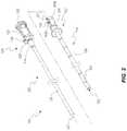
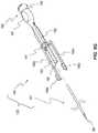
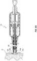
- FIG. 1is a perspective view of an embodiment of a tissue engagement system 100 .
- the tissue engagement system 100can be used to engage a tissue layer and to pierce the tissue layer to provide access to a region beneath the tissue layer.
- Certain embodimentscan be particularly well suited for engaging and piercing tissue layers that are relatively thin and/or are closely situated to an underlying structure.
- some embodimentsare well suited for engaging and piercing the pericardium, and can be configured to do so without contacting or damaging the underlying epicardium.
- Other features and advantages of various embodimentswill be apparent from the disclosure that follows.
- the tissue engagement system 100includes a tunneling system 101 and a tissue engagement system 102 . Stated otherwise, each of the tunneling system 101 and the tissue engagement system 102 is a subset of the tissue engagement system 100 .
- a tunneler cannula 110is common to both the tunneling system 101 and the tissue engagement system 102 . That is, the tunneler cannula 110 can be used with the tunneling system 101 to tunnel a path to a target tissue layer, and can further be used with the tissue engagement system 102 in the subsequent engagement and piercing of the target tissue layer.
- the tunneling system 101includes an obturator 120
- the tunneling system 102includes a tissue engagement device 130 .
- each of the obturator 120 and the tissue engagement device 130is configured to be selectively coupled with the tunneler cannula 110 .
- the tissue engagement system 100is provided as a kit 103 .
- the tunneler cannula 110 , the obturator 120 , and the tissue engagement device 130can be assembled as a set and distributed together, such as in unitary sterile packaging.
- the kit 103may exclude one or more of the obturator 120 or the tunneler cannula 110 .
- one or more of the tunneler cannula 110 , the obturator 120 , or the tissue engagement device 130can be distributed separately.
- the tunneler cannula 110includes a cannula, shaft, or tube 111 that defines a lumen 112 .
- the tunneler cannula 110can further include a connector 113 at a proximal end of the tube 111 .
- the connector 113can be of any suitable variety and can be configured to selectively couple/decouple the tunneler cannula 110 to/from the obturator 120 .
- the connector 113comprises a female snap fitting 114 that includes two resilient prongs 115 a , 115 b that are configured to flex outwardly relative to a longitudinal axis of the tunneler cannula 110 .
- a proximal end of each resilient prong 115 a , 115 bincludes an inwardly directed ridge 116 that can engage a complementary portion of the obturator 120 .
- the illustrated snap fitting 114includes a pair of diametrically opposed channels 117 (only one of which is shown in FIG. 2 ).
- the channels 117can facilitate flexion of the prongs 115 a , 115 b .
- the tunneler cannula 110can include one or more depth markings 118 of any suitable variety.
- the illustrated obturator 120includes a rod 121 that is sized to substantially fill the lumen 112 of the tunneler cannula 110 .
- an outer diameter of the rod 121can be slightly smaller than an inner diameter of the tube 111 to permit the obturator 120 to be readily inserted into and removed from the tube 111 , while still filling the lumen 112 to prevent coring thereby as the tube 111 is advanced through tissue (e.g., soft or connective tissue) of a patient.
- the term “diameter”is used in its broadest sense, and includes the definition of a straight line from one side of something to the other side that passes through the center point, or the distance through the center of something from one side to the other. That is, the term diameter does not necessarily imply a circular configuration.
- the drawingsgenerally depict circular or cylindrical symmetries, such as for the tube 111 and the rod 121 , the present disclosure contemplates non-circular configurations.
- various embodimentscan have non-circular cross-sectional profiles such as triangular, rectangular, polygonal, oval, etc.
- the term “diameter”refers to the maximum diameter of a given feature, or portion thereof, as will be apparent from context.
- the obturator 120can include a dull or blunt tip 122 that may be rounded at a distal end thereof.
- the tip 122may have a sufficiently steep pitch (e.g., be sufficiently sharp) to permit the obturator 120 to be readily advanced through tissue.
- the tip 122is, nevertheless, sufficiently blunt to prevent inadvertent puncturing or perforation of a target tissue layer when the tip 122 presses against the target tissue layer.
- the tip 122may be readily advanced through tissue of a patient toward the heart of the patient (e.g., by application of about 2 or 3 pounds of force), but when the tip 122 comes into contact with the heart (e.g., the pericardium) with the same amount of force, the tip 122 is stopped thereby and does not puncture the heart.
- the hearte.g., the pericardium
- the obturator 120can include a connector 123 that is configured to be selectively coupled with the connector 113 of the tunneler cannula 110 .
- the illustrated connector 123is a male snap fitting 124 that is complementary to the female snap fitting 114 of the tunneler cannula 110 .
- the snap fitting 124includes an inclined or camming surface 125 that spreads apart the prongs 115 a , 115 b until the ridges 116 are received into a groove 126 at a proximal end of the camming surface 125 . Any other suitable connection interface between the obturator 120 and the tunneler cannula 110 is contemplated.
- the obturator 120includes a pair of diametrically opposed ridges 127 , which may act as grips that can permit ready twisting of the tunneling system 101 during a tunneling event.
- the obturator 120can include an enlarged base 128 , which may be substantially flat, which may facilitate application of distally directed force to the tunneling system 101 during a tunneling event.
- the tissue engagement device 130can include coupling features similar or identical to those of the obturator 120 .
- the tissue engagement device 130includes a connector 133 having a camming surface 135 and a groove 136 that are the same as like-numbered, like-named features of the obturator. Accordingly, after a tunneling event, the obturator 120 can be readily removed from the tunneler cannula 110 and replaced with the tissue engagement device 130 .
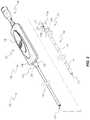
- the tissue engagement device 130can include an elongated housing or sheath 131 that defines a lumen 132 .
- the sheath 131can have an outer diameter that is slightly smaller than an inner diameter of the tube 111 .
- an outer diameter of the sheath 131can be no greater than about 0.15, 0.10, or 0.09 inches (3.8, 2.5, or 2.3 millimeters). In some embodiments, the outer diameter of the sheath 131 is about 0.96 inches (2.4 millimeters).
- a thickness of a sidewall of the sheath 131may also be selected to provide the sheath 131 with sufficient stiffness or rigidity to resist bending, while being narrow to provide a large amount of space for the components housed within the sheath 131 .
- the thickness of the sidewall of the sheath 131is no greater than about 0.005, 0.004, or 0.003 inches (0.13, 0.1, 0.08 millimeters).
- the sheath 131may be formed of any suitable material. In some embodiments, the sheath 131 comprises stainless steel.
- the tissue engagement device 130can include an actuation mechanism 137 that can include an actuation interface 138 via which a user can deploy a portion of the tissue engagement device 130 .
- the actuation interface 138comprises a button that can be pushed distally to actuate engagement arms or pulled proximally to retract the engagement arms after actuation, as further discussed below.
- the actuation mechanism 137can further include an access assembly 139 , which can be used to deploy an access device, such as a needle.
- the access assembly 139can be pushed distally to deploy the needle and can be pulled proximally to retract the needle after deployment, as discussed further below.
- the assembled housing 140can be sized to fit within the curvature of one or more curled, clenched, or gripped fingers of a user's hand.
- an external width of the assembled housing 140can be no greater than about 1 ⁇ 2 inch, 5 ⁇ 8 inch, 3 ⁇ 4 inch, 1 inch, or 1.5 inches (1.3, 1.6, 1.9, 2.5, or 3.8 centimeters). In some embodiments, the width is about 5 ⁇ 8 inches.
- an external length of the assembled housing 140can simultaneously contact up to 3 or up to 4 curled, clenched, or gripped fingers of one of a user's hands.
- the actuation interface 138can be movably coupled with the housing 140 .
- the actuation interface 138can be configured to be selectively translated distally (for actuation) or proximally (for retraction).
- a location of the actuation interface 138 relative to the housing 140can be ergonomically designed for ease of use.
- the actuation interface 138is configured to pass substantially through a center point of an upper surface of the upper shell 141 .
- the actuation interface 138may further be configured to move approximately equal distances from the center point in each of the distal and proximal directions. Other suitable configurations are also contemplated.
- the actuation interface 138may be conveniently located for single-handed operation thereof.
- the housingcan be gripped by multiple fingers of one hand of a user and the actuation interface 138 can be controlled by the thumb of that hand.
- FIG. 4Bdepicts a distal portion of the engagement element 143 in greater detail.
- the engagement element 143comprises a base 104 , which defines the proximal portion of the engagement element 143 .
- the base 104is a substantially tubular or cannular structure, and thus the base 104 may also be referred to as a cannular base.
- the cannular base 104defines a lumen 105 .
- an outer diameter of the baseis slightly smaller than an inner diameter of the sheath 131 .
- a plurality of flexible arms 108 a , 108 bextend distally from a distal end of the base 104 .
- the arms 108 a , 108 bmay also be referred to as tines or prongs.
- the arms 108 a , 108 bmay be integrally connected to the base 104 , in some embodiments, or stated otherwise, the base 104 and the arms 108 a , 108 b may be integrally formed from a unitary piece of material.
- the arms 108 a , 108 bmay be formed by cutting away (e.g., laser cutting) portions of a tube (see FIG. 9 ) and then bending the remaining protrusions.
- the arms 108 a , 108 bmay retain a bent configuration that extends transversely outward beyond an outer perimeter of the base 104 , such as, for example, the configuration depicted in FIGS. 10A and 10B .
- Each arm 108 a , 108 bcan include a tissue engaging member 109 a , 109 b that can embed within, pierce, or otherwise attach to a target tissue layer.
- the tissue engaging memberscan each include a pointed element, such as an angled end, spike, or barb, that can pierce into the target tissue layer.
- each tissue engaging member 109 a , 109 bincludes an angled distal end of the respective arm 108 a , 108 b.
- the engagement device 130can include an actuation member 145 that communicates movement of the actuation interface 138 at a proximal end thereof to a distal end of the actuation member 145 .
- the actuation member 145can be configured to deploy the arms 108 a , 108 b of the engagement element 143 .
- the actuation member 145comprises a tube or cannula. Accordingly, the actuation member 145 may also be referred to as an actuation cannula.
- the illustrated embodimentincludes a piercing member or access device 147 that is configured to create an access opening through the target tissue layer when deployed.
- the access device 147is a needle. Any suitable needle or other piercing member may be used.
- the actuation member 145can be positioned within the lumen 132 of the sheath 131 , and can be sized to slide or otherwise translate freely therein.
- the access device 147can be positioned within the lumen 105 of the actuation member 145 , and can be sized to slide or otherwise translate freely therein.
- the actuation mechanism 137can include multiple components that are configured to constrain operation of the tissue engagement device 130 .
- the actuation mechanism 137includes components that control the movement of the actuation member 145 relative to the engagement element 143 , and also relative to the access device 147 .
- the actuation mechanism 137includes components control the movement of the access device 147 relative to the actuation member 145 and the engagement element 143 .
- the actuation mechanismincludes a gate 144 that is received within the lower shell 142 of the housing, a shuttle 146 that is coupled with the actuation member 145 , and a hub 149 that is coupled with the access device 147 .
- the access assembly 139includes the hub 149 and the access device 147 .
- the actuation interface 138 , the shuttle 146 , and the actuation member 145may be referred to collectively herein as an actuation assembly 148 .
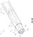
- FIGS. 5A-5Ddepict the tissue engagement system 102 in various operational states, which can correspond with method steps for using the system 102 . These figures depict a distal end of the assembled engagement system 102 . Although illustrative examples for achieving the operational states depicted in FIGS. 5A-5D can be achieve via the illustrated actuation mechanism 137 , as described further below with respect to FIGS. 6A-7E , it should be understood that any suitable systems and methods for achieving the operational states discussed are contemplated.
- FIG. 5Adepicts a distal portion of the tissue engagement device 130 positioned within a distal portion of the tunneler cannula 110 .
- the tube 111 of the tunneler cannulais shown as the outermost tube.
- the outer surfaces of the sheath 131 , the cannular base 104 , the actuation member 145 , and the access device 147are depicted in broken lines.
- This viewdepicts the compact configuration achieved by the nested, telescopic, or coaxial arrangement of the tube 111 , the sheath 131 , the cannular base 104 , the actuation member 145 , and the access device 147 .
- the arms 108 a , 108 b and the tissue engaging members 109 a , 109 bare also identified in FIG. 5A .
- the tissue engagement device 130may either be in the process of being advanced distally toward or through a distal end of the tube 111 or retracted proximally through the tube 111 .
- the pointed ends of the tissue engaging members 109 a , 109 bare at an interior of the tube 111 , or stated otherwise, are within the lumen 112 .
- the pointed endscannot inadvertently contact tissue (i.e., tissue at an exterior of the tube 111 ) during advancement through the tube 111 or retraction through the tube 111 .
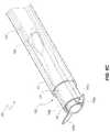
- FIG. 5Bdepicts the distal end of the tissue engagement device 130 advanced past a distal end of the tube 111 of the tunneler cannula 110 .
- the tissue engagement device 130is depicted in a fully retracted or unactuated state. In the fully retracted state, neither the arms 108 a , 108 b nor the access device 147 is deployed.
- the illustrated configurationcan represent a point in time after the system 102 has been advanced to the target tissue layer and just before deployment of the arms 108 a , 108 b.
- the engaging members 109 a , 109 b of the arms 108 a , 108 bare positioned slightly external to a distal end of the sheath 131 when the tissue engagement device 130 is in the fully retracted configuration. Stated otherwise, the engaging members 109 a , 109 b are positioned distally relative to a distal end of the sheath 131 .
- the exposed pointed tips of the engaging members 109 a , 109 bmay readily engage a target tissue layer upon contact therewith as the distal end of the sheath 131 is advanced into contact with the target tissue layer.
- the pointed tipsare directed in a slightly distal direction, such that initial contact of the pointed tips with the target tissue layer as the engagement device 130 is advanced distally through the tunneler cannula 110 can urge the pointed tips into the target tissue layer. Further, due to the slight exposure of the pointed tips past the distal end of the sheath 131 , abutting contact of the distal end of the sheath 131 against the target tissue layer can provide tactile feedback to the user that the tissue layer has been initially engaged and that deployment of the arms 108 a , 108 b can proceed.
- the engaging members 109 a , 109 b in the illustrated embodimentextend in a longitudinal direction, or distally, beyond the distal tip of the sheath 131 , the engaging members 109 a , 109 b are nevertheless restrained to a low-profile configuration in which they either do not extend or do not significantly extend laterally outward beyond a perimeter of the sheath 131 .
- the arrangement depicted in FIG. 5Bwere shown in an end-on view (directed proximally), similar to the view depicted in FIGS. 11D and 13 , the full perimeter of the distal end of the sheath 131 would be visible in situations where the engaging members 109 a , 109 b do not extend laterally outward beyond the perimeter.
- the engaging members 109 a , 109 bwould appear to be interior to the perimeter. Stated otherwise, if an outer surface of the sheath 131 were projected distally beyond the distal end of the sheath 131 , either all or substantially all (e.g., no less than 75 percent) of the engaging members 109 a , 109 b would be encompassed or circumscribed thereby. Such an arrangement can inhibit or avoid interaction (e.g., snagging, tearing, etc.) between the engaging members 109 a , 109 b and tissue that is positioned outside the perimeter of the sheath 131 . This can be advantageous either during deployment of the tissue engagement device 130 beyond the distal end of the tunneler cannula 110 or during retraction of the engagement device 130 into the tunneler cannula 110 .
- the remainder of the arms 108 a , 108 bare positioned within the lumen 132 of the sheath 131 . As discussed further below, and as depicted in FIG. 5B , the arms 108 a , 108 b cross each other at a position that is within the lumen 132 and that is distal to a distal end of the actuation member 145 .
- FIG. 5Cdepicts the tissue engagement system 102 after the arms 108 a , 108 b have been deployed.
- the actuation member 145has been advanced distally beyond the position at which the arms 108 a , 108 b crossed each other, thereby uncrossing the arms 108 a , 108 b and deforming them from the undeployed configuration depicted in FIG. 5B .
- the actuation member 145has forced a proximal portion of the arms 108 a , 108 b into an annular region between an outer surface of the actuation member 147 and an inner surface of the sheath 131 .
- the arms 108 a , 108 bare at diametrically opposite sides of the device 130 (e.g., at opposite sides of the cannular base 104 ). As further discussed below, deployment of the arms 108 a , 108 b moves the engaging members 109 a , 109 b in substantially opposite directions. The engaging members 109 a , 109 b thus can embed within and/or apply tension to the target tissue layer in substantially opposite directions.
- the arms 108 a , 108 bare in a high-profile configuration in which they extend laterally outwardly beyond a perimeter of the sheath 131 .
- the tissue engagement device 130is in a partially deployed state, in that the arms 108 a , 108 b are deployed, but the access device 147 remains retracted. Deployment of the arms 108 a , 108 b clears the engaging members 109 a , 109 b away from the distal end of the actuation member 145 to provide an unobstructed passageway for deployment of the access device 147 . Stated otherwise, in the configuration depicted in FIG. 5B , the arms 108 a , 108 b cover a distal end of the actuation member 145 . Deployment of the arms 108 a , 108 b effectively uncovers the distal end of the actuation member 145 to provide an access pathway for the access device 147 .
- the term “cover”does not require direct contact against a surface (e.g., the distal end of the actuation member 145 ), although such an arrangement is subsumed within this term.
- the term “cover”is used more broadly herein, and includes situations of obstruction without direct contact. For example, if the arrangement depicted in FIG. 5B were shown in an end-on view (directed proximally), similar to the view depicted in FIG. 13 , rather than perspective, much of the opening in the distal end of the actuation member 145 would be obstructed from view by the arms 108 a , 108 b .
- the distal opening of the actuation member 145would appear to be obstructed. Stated otherwise, if an inner surface of the actuation member 145 that defines the distal opening of the actuation member 145 were projected distally beyond the distal end of the actuation member 145 , the arms 108 a , 108 b would be encompassed or circumscribed thereby.
- the actuation mechanism 137can prevent deployment of the access device 147 prior to deployment of the arms 108 a , 108 b via the actuation member 145 . This can be a safety measure to ensure that the user does not inadvertently partially deploy the arms 108 a , 108 b by moving the access device 147 distally past the arms.
- the outer diameter of the access device 147is only slightly smaller than the outer diameter of the actuation member 145 , deployment of the access device 147 prior to deployment of the actuation member 145 could extend the engaging members 109 a , 109 b laterally outwardly to a relatively high-profile configuration, though potentially not quite as wide or as high-profile an arrangement as can be achieved by deployment of the actuation member 145 .
- FIG. 5Ddepicts the tissue engagement device 130 in a fully deployed state.
- the engagement arms 108 a , 108 bare deployed and the access device 147 is also deployed.
- the access device 147has been advanced distally through the actuation member 145 and beyond the distal end thereof.
- the actuation mechanism 137can prevent the actuation member 145 from retracting the engagement arms 108 a , 108 b unless the access device 147 is first retracted. This can serve as a safety precaution, as retraction of the actuation member 145 without first retracting the access device 147 could leave the arms 108 a , 108 b in a partially deployed state.
- the access device 147has an outer diameter that is slightly smaller than an outer diameter of the actuation member 145 .
- the resilient arms 108 a , 108 bwould begin to return to the low-profile configuration upon retraction of the actuation member 145 , but would be prevented from reaching this configuration by instead coming into contact with the outer surface of the access device 147 .
- the usercould potentially think that the arms 108 a , 108 b had been fully retracted at this stage, due to the retraction of the actuation member 145 , and could withdraw the tissue engagement device 130 with the arms 108 a , 108 b in the partially deployed state. Distal movement of the tissue engagement device 130 in this state could potentially damage the target tissue layer, overlying tissue, and/or the engagement device 130 itself.
- a method of retracting the system 102 from a patientcan follow the stages depicted in FIGS. 5A-5D in reverse order. For example, beginning with the configuration depicted in FIG. 5D , the access device 147 can be retracted to the orientation depicted in FIG. 5C . Thereafter, the actuation member 145 can be retracted to the orientation depicted in FIG. 5B . In certain embodiments, due to resilience of the arms 108 a , 108 b , this retraction of the actuation member 145 will also case the arms 108 a , 108 b to naturally or automatically return from the deformed condition in FIG. 5C to the configuration depicted in FIG. 5B . Thereafter, the tissue engagement device 130 can be withdrawn through the lumen of the tunneling cannula 110 , as depicted in FIG. 5A .
- FIGS. 6A-6Gdepict an illustrative embodiment of the actuation mechanism 137 for the tissue engagement device 130 .
- the illustrated actuation mechanism 137is capable of preventing two potentially undesirable configurations of the tissue engagement device 130 .
- the actuation mechanism 137is configured to prevent the access device 147 from being deployed prior to deployment of the arms 108 a , 108 b via the actuation member 145 , which can avoid the potentially undesirable results for such a configuration discussed above.
- the illustrated actuation mechanism 137is further configured to prevent retraction of the actuation member 145 and the resultant retraction of the arms 108 a , 108 b , which can avoid the potentially undesirable results for such a configuration discussed above.
- the illustrated actuation mechanism 137may be referred to as a dual interlock system or as a locking mechanism. Stated otherwise, the actuation mechanism 137 can serve as a lock to prevent a first potentially undesirable configuration of the tissue engagement device 130 , and can further serve as a lock to prevent a second potentially undesirable configuration of the tissue engagement device 130 .
- an interlock devicemay prevent only one of the potentially undesirable configurations. In still other embodiments, the actuation mechanism 137 may not function as an interlock device for either potentially undesirable configuration.
- FIG. 6Adepicts an exploded perspective view of an embodiment of the housing 140 , which includes the upper shell 141 and the lower shell 142 .
- the lower shell 142can include the connector 133 at a distal end thereof, as previously described.
- the connector 133can define a lumen 133 a through which the actuation member 145 and the access device 147 can pass for advancement to a deployed state or retraction to a retracted state.
- the lower shell 142can define a cavity 150 a into which certain components of the actuation mechanism 147 , or portions thereof, can be received.
- the upper shell 141likewise defines a cavity 150 b into which certain components or portions thereof can be received.
- the cavities 150 a , 150 bdefine a unitary volume of space.
- the dual interlock property of the illustrated embodiment of the actuation mechanism 137generally operates on two levels or planes.
- the upper levelis generally defined by a lower portion of the upper shell 141 .
- the lower levelis defined by the lower shell 142 .
- the lower shell 142includes an actuator stop 151 , which is a rounded protrusion that extends upwardly from a substantially flat base wall of the lower shell 142 .
- the actuator stop 151is configured to interact with a component in the lower level.
- the key slot regions 155 a , 155 bdefine a unitary key slot, and the keying surfaces 153 a , 153 b cooperate to maintain a fixed rotational orientation of the hub 149 as portions thereof are advanced distally into or retracted proximally from the housing 140 .
- the upper shell 141defines a pair of stops 159 a , 159 b that can selectively prevent proximal movement of the shuttle 146 , as further described below.
- the stops 159 a , 159 breside within the upper level along which the dual interlock mechanism operates.
- the illustrated actuation interface 138is formed as a button 160 , which may also be referred to as a slider.
- the illustrated button 160is particularly well suited for actuation via a thumb of a user while the housing 140 is held by fingers of the hand, although other actuation grips are possible.
- the button 160includes a proximal surface 161 that is contoured to receive a thumb tip of a user.
- the proximal surface 161rises in a distal direction toward a grip 163 , which can provide traction for the user.
- the illustrated gripincludes transversely directed grooves.
- a distal surface 162drops steeply from the apex. The user can readily grip the apex and/or upper portions of the distal surface 162 to apply rearward directed force for retraction of the actuation assembly 148 .
- the button 160can include a longitudinal guide 164 that is sized to slide within the longitudinal channel 157 of the upper shell 141 .
- the button 160can further include a lateral retainer or transverse bar 165 that cooperates with a bottom surface of the button 160 to define a channel 166 on either side of the guide 164 .
- the channels 166can receive a portion of the upper shell 141 that borders the longitudinal channel 157 .
- FIGS. 6D and 6Edepict the gate 144 in two different operational states.
- the gate 144is closed, whereas the gate 144 is open in FIG. 6E .
- the gate 144is positioned within the lower shell 142 . Accordingly, the gate 144 operates in the lower level of the dual interlock mechanism.
- the gate 144includes a base 170 from which two resilient arms 171 a , 171 b extend in the proximal direction.
- the base 170defines an opening 172 sized to receive the coupling protrusion 152 of the lower shell 142 to connect the gate 144 to the lower shell 142 .
- the distal ends of the arms 171 a , 171 bcooperate with an inner surface of the base 170 to define a receptacle 173 .
- the actuator stop 151resides within the receptacle 173 .
- central portions of the arms 171 a , 171 binclude inwardly projecting camming surfaces 174 a , 174 b , respectively.
- the camming surfaces 174 a , 174 bare configured to interact with a portion of the shuttle 146 to selectively open the gate 144 , as further described below.
- the proximal ends of the arms 171 a , 171 binclude stops 175 a , 175 b that are configured to abut a portion of the hub 149 to prevent distal movement of the hub 149 when the gate 144 is in the closed state of FIG. 6D .
- the stops 175 a , 175 bare separated from each other to define a passageway 176 through which the portion of the hub 149 can pass in the distal direction.
- FIG. 6Fdepicts a portion of the actuator 148 , which includes the actuation member 145 and the shuttle 146 . As previously mentioned, the actuator 148 further includes the actuation interface 138 .
- the actuation member 145is a cannula that defines a lumen 180 .
- the lumen 180is sized to permit passage of the access device 147 .
- a proximal end of the actuation member 145can be coupled to a body 181 of the shuttle 146 in any suitable manner.
- the shuttle 146includes a pair of upwardly projecting sidewalls 182 that cooperate to define a longitudinal channel 183 and a lateral channel 187 .
- the channels 183 , 187are sized to receive the longitudinal guide 164 and the transverse bar 165 that project downwardly from the button 160 .
- the longitudinal guide 164 and the transverse bar 165are inserted through the longitudinal channel 157 and the transverse channel 158 of the upper shell 141 and into the longitudinal channel 183 and the lateral channel 187 of the shuttle 146 .
- the button 160 and the shuttle 146can be connected together in any suitable manner, including one or more of friction fit, snap fit, adhesive, etc. Once the button 160 and the shuttle 146 are connected, the button 160 is free to slide forward and rearward within the longitudinal channel 157 of the upper shell.
- the shuttle 146further includes a downward protrusion, such as a wedge 184 .
- the wedge 184is configured to operate on the lower plane of the interlock mechanism.
- the wedge 184can be positioned between the proximal portions of the arms 171 a , 171 b of the gate 144 .
- the wedge 184can include camming surfaces that interact with the camming surfaces 174 a , 174 b of the gate 144 to urge apart the resiliently flexible arms 171 a , 171 b .
- the wedge 184can interact with the actuator stop 151 ( FIG. 6A ) to prevent the shuttle from traveling too far in a distal direction.
- the stop 151may be positioned so as to ensure that a distal end of the actuation member 145 stops at a desired position relative to the actuated arms 108 a , 108 b (see FIG. 5C ), such as, for example, a position that is slightly proximal of the tissue engaging members 109 a , 109 b of the actuated arms 108 a , 108 b .
- a desired positionsuch as, for example, a position that is slightly proximal of the tissue engaging members 109 a , 109 b of the actuated arms 108 a , 108 b .
- Such as positionmay, for example, avoid pushing an engaged portion of the target tissue layer off of the actuated engaging members 109 a , 109 b.
- the illustrated embodiment of the shuttle 146includes a pair of laterally and proximally projecting resiliently flexible arms 185 a , 185 b .
- the arms 185 a , 185 binclude stops 186 a , 186 b at the proximal ends thereof.
- the arms 185 a , 185 b and stops 186 a , 186 bare positioned to operate on the upper level of the interlock mechanism.
- the arms 185 a , 185 bmay be flexed inwardly as the actuator 148 is advanced distally to deploy the arms 108 a , 108 b via the actuation member 145 via contact with a portion of the hub 149 , as discussed further below.
- the arms 108 a , 108 bcan automatically return to a natural extended state, at which point the stops 186 a , 186 b engage the stops 159 a , 159 b of the upper shell 141 .
- the shuttle 146can be retained in this position until the hub 149 is returned to a proximal position to free the stops 186 a , 186 b from the stops 159 a , 159 b , as discussed further below with respect to FIG. 7E .
- FIG. 6Gdepicts the access assembly 139 , which includes the access device 147 or piercing member and the hub 149 .
- a proximal end of the access device 147can be coupled to a body 191 of the hub 149 in any suitable manner.
- the access device 190can define a lumen 190 through which communication with a region beneath the target tissue layer (e.g., the pericardial space) can be established once the access device 147 pierces through the target tissue layer.
- a guide wiremay be delivered through the lumen 190 .
- the hub 192includes a neck 192 that is shaped to fit within the key slot defined by the keying surfaces 153 a , 153 b of the lower and upper shells 142 , 141 .
- the neck 192can include outwardly projecting flanges that, in cooperation with the keying surfaces 153 a , 153 b , prevent rotational movement of the hub 149 about a longitudinal axis thereof.
- the hub 192can include a grip 197 , which may be positioned proximal of the neck 192 .
- the grip 197can be sized and configured to be readily manipulated by a user, such as by using a second hand while the user holds the housing 140 with a first hand.
- a medical connector 198is positioned at a proximal end of the hub 192 . Any suitable connection interface is contemplated for the medical connector 198 , which can serve to couple the hub 149 with any suitable medical device(s) or equipment for delivering and/or withdrawing fluid to/from a region accessed by the distal end of the access device 147 .
- the connector 198comprises a Luer fitting 199 .
- the hub 149includes three distally projecting tines, prongs, or arms 193 , 194 a , 194 b .
- the arms 193 , 194 a , 194 bsubstantially form a trident shape.
- the central arm 193is shorter than the outer arms 194 a , 194 b and includes a stop 195 at a distal end thereof.
- the stop 195operates at the lower level of the interlock system, and is configured to interact with the stops 175 a , 175 b of the gate 144 .
- An upward protrusion 196 a , 196 bis positioned at the distal end of each of the side arms 194 a , 194 b .
- the protrusions 196 a , 196 bare positioned to operate at the upper level of the interlock system.
- the protrusions 196 a , 196 bare configured to bend the proximal ends of the arms 185 a , 186 a inward when the hub 149 is drawn proximally to a retracted state, thereby permitting proximal movement of the shuttle to a retracted state, as shown in and discussed further with respect to FIG. 7E .
- Some of the features of the illustrated actuation mechanism 137include a pair of elements to accomplish a given function.
- the two arms 185 a , 186 ainteract with the two stops 159 a , 159 b to prevent retraction of the actuation member 145 under certain conditions.
- only a single set of interacting featuresmay be used.
- a redundant set of interacting featurescan provide strength, stability, and/r balance to the system and/or act a as a backup or failsafe.
- FIGS. 7A-7Edemonstrate various stage of operation of the actuation mechanism 137 . Many details regarding these stages of operation have already been provided. FIGS. 7A-7E and the discussion that follows are to provide further clarity regarding to the manners in which the various components interact (e.g., to achieve a dual interlock mechanism). Certain features that were discussed with respect to at least FIGS. 5A-6G may not be repeated in the following discussion, as the purpose of the present discussion is to provide a streamlined understanding of the illustrated actuation mechanism 137 . The further details disclosed with respect to at least FIGS. 5A-6G are fully applicable here, but will be omitted for the sake of brevity and clarity.
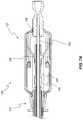
- FIG. 7Ais a cross-sectional view of the tissue engagement device 130 along the view line 7 A- 7 A in FIG. 1 , as coupled with the tunneler cannula 110 , which is also shown in cross-section.
- This drawingdepicts the shuttle 146 in a fully retracted configuration.
- the drawingdepicts the actuation member 145 in the retracted configuration.
- the access device 147 and the hub 149are in the retracted configuration.
- the tissue engagement device 130is in the fully retracted configuration.
- FIG. 7Acorresponds with the view of the distal end of the tissue engagement device 130 depicted in FIG. 5B .
- the gate 144is closed and interacts with the central prong 193 of the hub 149 to prevent deployment of the access device 147 .
- the tissue engagement device 130is in a partially deployed state.
- the shuttle 146has been advanced distally, but not yet to its distal-most orientation. That is, the shuttle 146 has been advanced to an intermediate phase of deployment.
- the gate 144has begun to open, but is not yet open sufficiently wide to permit the distal passage of the central prong 193 of the hub 149 .
- FIG. 7Cdepicts the actuation mechanism 137 of the tissue engagement device 130 in another partially deployed state.
- the shuttle 146has been advanced to its distal-most position, and is thus fully deployed.
- the hub 149 and the access device 147remain in their retracted state.
- the full distal movement of the shuttle 146has opened the gate 144 to create the passageway 176 , which is now sufficiently large to permit passage of the central prong 193 of the hub 149 in a distal direction.
- FIG. 7Ccorresponds with the view of the distal end of the tissue engagement device 130 depicted in FIG. 5C .
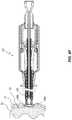
- FIG. 7Ddepicts the actuation mechanism 137 of the tissue engagement device 130 in a fully deployed state. Specifically, the shuttle 146 and the actuation member 145 are in their distal-most orientations, and the hub 149 has been moved distally to at least partially deploy the access device 147 .
- the hub 149is able to move distally and proximally in an unconstrained manner, or at least unconstrained within a range permitted by the confines of the housing 140 .
- Unconstrained distal movementpermits a user to select the amount of force to be applied to the access device 147 to pierce the target tissue layer, as well as the distance (within a limited range) to which the access device 147 will be inserted through the tissue layer.
- Unconstrained proximal movementcan be an advantageous safety feature, in some instances.
- a userinserts the access device 147 through the tissue layer, but then becomes distracted or otherwise inadvertently releases the hub 149 , the underlying layer can be protected from damage, such as by pushing the access device 147 in the proximal direction.
- a distal tip of the access device 147may be readily pushed rearward by the beating heart if the practitioner maintains a grip on the housing 140 , but releases a grip on the hub 149 .
- Movement of the hub 149 and its upward protrusions 196 a , 196 b in the distal directionreleases the arms 185 a , 185 b of the shuttle 146 to automatically resiliently expand outwardly into contact with the sides of the housing 140 .
- the proximal ends of the arms 185 a , 185 bcome into contact with the distal faces of the stops 159 a , 159 b , which prevents the shuttle 146 from moving distally in the present configuration.
- FIG. 7Edepicts the actuation mechanism 137 in a partially deployed state again, with the hub 149 having been withdrawn distally to a configuration that permits retraction of the actuation member 145 .
- movement of the hub 149 and its upward protrusions 196 a , 196 b in the proximal directioncompresses the arms 185 a , 185 b of the shuttle 146 to be displaced inward and out of contact from the distal faces of the stops 159 a , 159 b .
- This configurationpermits proximal movement of the shuttle 146 to draw the actuation member 145 into the retracted position.
- FIGS. 8A-8Kdepict various stages of illustrative methods for engaging a target tissue layer and accessing a space beneath the same. Many details regarding these method stages have already been provided. FIGS. 8A-8K and the discussion that follows are to provide further clarity regarding to the methods. Certain features that were discussed with respect to at least FIGS. 5A-7E may not be repeated in the following discussion, as the purpose of the present discussion is to provide a streamlined understanding of the illustrated method stages. The further details disclosed with respect to at least FIGS. 5A-7E are fully applicable here, but will be omitted for the sake of brevity and clarity.
- One illustrative methodincludes each stage depicted in FIGS. 8A-8K in the sequential order shown.
- the pericardial space of the heart of a patientis accessed.
- Other methodsare contemplated, including some that do not employ each method stage illustrated and/or that use additional stages.
- other suitable contextse.g., target tissue layers other than the pericardium are contemplated.
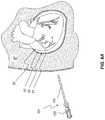
- FIG. 8Adepicts an early stage of an illustrative method for accessing a region beneath a tissue layer.
- the methodis used to access the pericardial space 53 between the pericardium 51 and the epicardium 52 of the heart 50 of a patient P.
- the tunneling assembly 101is provided, such as by being removed from sterile packaging.
- the obturator 120 and the tunneling cannula 110are provided in a preassembled state.
- an earlier stage of the methodinclude coupling the obturator 120 to the tunneling cannula 110 into the configuration show.
- an anterior approachmay be used in directing the tunneling assembly 101 toward the heart 50 .
- an inferior or posterior approachis used, which can require passing the tunneling assembly 101 through the diaphragm.
- Such an approachmay also referred to as a transdiaphragmatic or subdiaphragmatic approach.
- Each such approachmay be referred to as a subxiphoid approach.
- the different approachesmay result in different angles relative to the heart.
- an intercostal approache.g., between the 6th and 7th ribs may be used and may provide direct access to different areas of the heart. In some instances, the intercostal space allows the apex of the heart to be accessed, and so such an approach is also called a transapical approach.
- tissue engagement systems 100 , 102 and tissue engagement devices 130 disclosed hereincan be particularly well suited for any such approach to the heart.
- the systems 100 , 102 and devices 130can be particularly well suited to engage, grasp, pull, and or otherwise manipulate the pericardium 51 at any number of different approach angles.
- the tissue engagement devices 130can work effectively at shallow angles of approach or steep angles of approach.
- certain embodimentsare capable of functioning well at approach angles of from 0 degrees (e.g., a fully transverse orientation) through 90 degrees (e.g., a fully orthogonal orientation).
- a distal end of the device 130can come into contact with the pericardium and create a ripple, or a substantially vertical (or upwardly extending) wall of tissue ahead of the distal end of the device.
- This phenomenonis similar to pushing a piece of fabric along a tabletop using a finger to generate a ripple or wave response.
- a local wave or ripplecan create an at least somewhat transverse surface, relative to a distal end of the device 130 , to which the tines can engage (e.g., grasp, grab, embed within, snag, catch, etc.)
- FIG. 8Bdepicts a stage at which the tunneling assembly 101 has been advanced through an incision 56 in the skin 55 of the patient.
- the blunt tip 122 of the obturator 120has been urged through the connective tissue 54 of the patient P into contact with an external surface of the pericardium 51 .
- FIG. 8Cdepicts a stage at which the obturator 120 is decoupled from the tunneling cannula 110 and removed therefrom.
- the tube 111 portion of the tunneling cannula 110is left in the tissue 54 to provide a channel to the pericardium 51 .
- FIG. 8Ddepicts a stage in which the tissue engagement device 130 is coupled with the tunneler cannula 110 .
- the sheath 131is advanced through the tube 111 and toward the pericardium 51 .
- FIG. 8Edepicts another stage in which the tissue engagement device 130 is in the fully retracted configuration, such as that of FIGS. 5B and 7A , with the tissue engagement members 109 a , 109 b (e.g., the distal tips) of engagement arms 108 a , 108 b positioned at the target tissue layer, which in this instance is the pericardium 51 .
- the tissue engagement device 130is fully coupled with the tunneler cannula 110 .
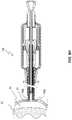
- FIG. 8Fdepicts another stage in which the tissue engagement device 130 is in the partially deployed state, such as that of FIG. 7B , with the actuation member 145 advanced distally to an intermediate position to embed the tissue engagement members 109 a , 109 b arms in the pericardium 51 .
- the tissue engagement members 109 a , 109 bdo not extend through a full thickness of the pericardium 51 to pass into the pericardial space 53 . Stated otherwise, the engagement members 109 a , 109 b do not pass through an interior or bottom surface of the pericardium 51 .
- shallow deployment pathit is meant that the path traced by the engagement members 109 a , 109 b (e.g., a distal tip thereof) extends only a small longitudinal distance from the distal end of the actuation member 145 , or from the starting point of the respective engagement member 109 a , 109 b .
- each engagement member 109 a , 109 bprogresses distally from its staring point to a maximum longitudinal distance (i.e., a distance as measured only in the longitudinal direction, or in a direction that is collinear with or parallel to a longitudinal axis of the actuation member 145 ) that is no greater than 1, 2, 3, or 4 millimeters.
- a maximum longitudinal distancei.e., a distance as measured only in the longitudinal direction, or in a direction that is collinear with or parallel to a longitudinal axis of the actuation member 145
- an entirety of the path traced by each engagement member 109 a , 109 bmay have no longitudinal component (e.g., may be entirely lateral), or may have a longitudinal component that progresses only in the proximal direction, or stated otherwise, only moves laterally and proximally from the starting point.
- each engagement member 109 a , 109 bdefines a maximum length.
- the maximum length of each engagement member 109 a , 109 bis the distance from the distal point thereof to a primary bend (e.g., the only bend in each arm 108 a , 108 b that is readily apparent in FIG. 8F ).
- each engagement member 109 a , 109 bprogresses distally from its starting point to a maximum longitudinal distance that is no greater than 0.25, 0.5, 0.75, 1, 1.25, or 1.5 times the maximum length of the engagement member 109 a , 109 b.
- each engagement member 109 a , 109 bfollows a deployment path that is substantially transverse to the surface of the target tissue layer.
- the substantially transverse deployment of the engagement members 109 a , 109 bcan embed the engagement members 109 a , 109 b within the tissue layer and can put the tissue layer under tension in the transverse direction.
- a substantially transverse deployment pathalso reduces the risk of contacting and/or damaging an underlying tissue layer, such as the epicardium 52 .
- At least a portion of one or more of the engagement members 109 a , 109 bmay extend through a full thickness of the target tissue layer. Stated otherwise, in other embodiments, the engagement members 109 a , 109 b may pierce through the bottom or inner surface of the tissue layer.
- the each of the engagement members 109 a , 109 bdefines an angle relative to a distal projection of longitudinal axis of the device 130 . In various embodiments, this angle can be no less than 60, 70, or 80 degrees throughout movement of the actuation cannula 145 from the retracted position to the extended position.
- FIG. 8Gdepicts a stage in which the tissue engagement device 130 is in the further partially deployed state, such as that of FIGS. 5C and 7C , with the actuation member 145 advanced to the distal-most position to further embed the engagement members 109 a , 109 b in the pericardium 51 .
- the engagement members 109 a , 109 bextend laterally outward at an angle of approximately 90 degrees relative to the adjacent, proximal portions of the arms 108 a , 108 b .
- Other angles relative to the arms 108 a , 108 b in this fully deployed stateare also contemplated, as further discussed below.
- FIG. 8Hdepicts a stage in which the tissue engagement device 130 is in the same configuration as that depicted in FIG. 8G and in which the tissue engagement device 130 is drawn proximally to enlarge the pericardial space 53 between the pericardium 51 and the epicardium 52 in the vicinity of the engagement members 109 a , 109 b .
- Such a separation eventmay result in tenting of the pericardium 51 at the engagement position.
- This tentingis shown only schematically in FIG. 8H , as the tenting can be quite steep in some instances, such as may result from vacuum or other forces within the pericardial space 53 as the pericardium 51 is drawn upward in the manner shown.
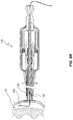
- FIG. 8Idepicts a stage in which the tissue engagement device 130 has been moved to the fully deployed state, such as that of FIGS. 5D and 7D , in that both the actuation member 145 and the access device 147 have been advanced distally.
- the access device 147has pierced the pericardium 51 to provide access to the pericardial space 53 .
- Communication with pericardial space 53can be achieved via the medical connector 198 .
- tenting in the vicinity of the actuation arms 108 a , 108 bmay be quite steep. However, the region between the arms 108 a , 108 b may be substantially planar due to tension provided by the arms 108 a , 108 b .
- the access device 147thus may be readily advanced through the portion of the pericardium 51 that is held in tension, which is relatively unaffected by the neighboring tenting.
- a distal end of the access device 147may be pointed, or angled relative to a longitudinal axis of the device.
- insertion of the device 147is much easier through a planar region that is substantially orthogonal to the longitudinal axis of the device—e.g., through the region between the arms 108 a , 108 b —than it is through regions that have shallower angles relative to the tip, such as the steep tented surfaces that surround the region that is held between the arms 108 a , 108 b .
- a tip of the access device 147passes through a line that extends between the arms 108 a , 108 b when the arms 108 a , 108 b are in the deployed state.
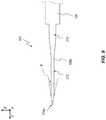
- FIG. 8Jdepicts a stage in which the tissue engagement device 130 remains in the fully deployed state and a distal end of a guidewire 200 has been advanced distally through the access device 147 into the pericardial space 53 .
- the guidewire 200may be of any suitable variety or size. In various embodiments, a thickness of the guidewire can be 0.035 inches (0.89 millimeters) or 0.032 inches (0.81 millimeters).
- FIG. 8Kdepicts another stage in which the tissue engagement device 130 has been returned to the partially deployed state, such as that of FIGS. 5C and 7C .
- the access device 147has been retracted.
- the actuation member 145may subsequently be retracted and then the device 130 can be removed from the patient P.
- the distal end of the guidewire 200can remain in place within the pericardial space 53 as the tissue engagement device 130 is withdrawn.
- the armswill be in a retracted state during removal of the device 130 , positioning of the guidewire 200 will be relatively unaffected during withdrawal of the device 130 .
- the arms 108 a , 108 bpass by the guidewire 200 .
- the guidewire 200can pass through openings 225 , 226 defined by the arms 108 a , 108 b , even though the arms 108 a , 108 b cover the distal opening of the actuation member 145 .
- the openings 225 , 226can be seen, for example, in FIGS. 11C and 11D .
- portions of the tubeare cut or otherwise removed to form the arms or tines 108 a , 108 b (the tine 108 b is hidden in FIG. 9 , but is shown in other figures, such as FIG. 10A ).
- the tinesare laser cut.
- the tines 108 a , 108 bcan extend distally from the remaining portion of the original tube, which is also referred to herein as the cannular base 104 .
- the tines 108 a , 108 bcan each include a relatively wide base region 210 , which can extend distally from a distal end of the cannular base 104 .
- a width of the base region 210can be no greater than about 2 ⁇ 3, 1 ⁇ 2, or 1 ⁇ 3 of a diameter of the cannular base 104 .
- the base region 210can have an angled step down to a displacement region 212 .
- the displacement region 212 of each armis the region of greatest displacement during use.
- a thinner displacement region 212can permit a compact or low profile design.
- a thin displacement regioncan be desirable where the tines 108 a , 108 b cross one another in the retracted orientation and move past each other during deployment.
- a thickness of the displacement regionis no greater than about 1 ⁇ 2, 1 ⁇ 3, 1 ⁇ 4, 1 ⁇ 6, or 1 ⁇ 8 of the diameter of the cannular base 104 .
- Removal of portions of the original tubecan also yield a piercing surface 214 a , 214 b (see also, e.g., FIG. 10A ).
- the piercing surfaces 214 a , 214 bare fashioned as pointed ends or barbs at the distal tips of each tine 108 a , 108 b .
- An attack angle ⁇ of the piercing surfaces 214 a , 214 bcan be selected to provide ready engagement with the target tissue layer. In various embodiments, the attack angle ⁇ is no greater than about 10, 15, 20, 25, or 30 degrees.
- FIG. 10Ais a side elevation view of the engagement element 143 after further processing
- FIG. 10Bis a top plan view thereof.
- the tines 108 a , 108 bare bent about multiple axes.
- a primary bend 216 a , 216 bis made by rotating the distal end of the tines 108 a , 108 b about the y-axis.
- the tine 108 ais rotated in a first direction about the y-axis
- the tine 108 bis rotated in an opposite direction about the y-axis.
- an angle of plastic deformation that results from the bendingcan be within a range of from about 30 degrees to about 120 degrees, from about 45 degrees to about 115 degrees, or may be no more than about 45, 60, 90, or 115 degrees.
- the primary bends 216 a , 216 bcan yield the engaging members 109 a , 109 b .
- Retention surfaces 219 a , 219 b at the proximal sides of the engaging members 109 a , 109 bmay vary in effectiveness at holding the target tissue layer, depending on the angle of plastic deformation of the bends 216 a , 216 b.
- the tines 108 a , 108 bcan be rotated and permanently bent in the same direction about the z-axis. Additionally, or alternatively, the tines 108 a , 108 b can be rotated and permanently bent in opposite directions about the x-axis. The latter bending may be referred to as splining, and can permit the tines 108 a , 108 b to move past one another when an additional permanent bend, or secondary bend 218 a , 218 b ( FIG. 10 ) is formed.
- the tines 108 a , 108 bdefine a natural orientation in which the lateral width at a distal end of the tines 108 a , 108 b is greater than a diameter of the cannular base 104 .
- the tines 216 a , 216 bare received within the sheath 131 , which has an interior diameter that only slightly exceeds the outer diameter of the base 104 , the tines 108 a , 108 b are spring-loaded. That is, the tines 108 a , 108 b naturally attempt to assume the configuration shown in FIGS.
- FIGS. 11A-11Ddepict various views of the engagement element 143 when in the constrained configuration that is provided by the sheath 131 , such as in the arrangement depicted in FIG. 5B .
- the sheath 131is not shown in these views.
- the tines 108 a , 108 bcross each other at a position distal of the distal end of the cannular base 104 .
- the tines 108 a , 108 bcontact one another at a crossing point 220 .
- Other embodimentsmay cross one another near a crossing point, but not contact each other thereat.
- the crossing point in such arrangementsmay be the midpoint of a minimum distance between the tines 108 a , 108 b where they cross.
- the tines 108 a , 108 bcan define openings 225 , 226 through which a guidewire may readily pass during use.
- the tines 108 a , 108 bcan be positioned diametrically opposite one another. When in a retracted state, the tines 108 a , 108 b can be in a substantially bent configuration. When actuated, a proximal portion of each tine 108 a , 108 b that is constrained within the sheath 131 can be substantially straightened. The straightened tines may be substantially parallel to each other and/or substantially parallel to a longitudinal axis of the cannular base 104 . A length of each tine 108 a , 108 b may be sufficiently long to prevent plastic deformation of the tines 108 a , 108 b during deployment. The tines are formed in an elastically resilient fashion that permits them to automatically and naturally return to the pre-deployment state after deployment.
- the first and second piercing surfaces 214 a , 214 bare moved at an exterior of the sheath throughout transition of the actuation cannula from the retracted position to the extended position.
- the actuation cannula 245defines a longitudinal axis, and the first and second tines 108 a , 108 b rotate about the longitudinal axis as the actuation cannula transitions from the retracted position to the extended position. Stated otherwise, the first and second tines 108 a , 108 b can progress toward their pre-bent state during actuation, and can return to their formed condition during retraction.
- certain embodiments of the engagement element 143can include a centering protrusion 230 .
- the centering protrusion 230is an inwardly directed bump 230 that is impressed into the cannular base 104 .
- the centering protrusion 230may instead be formed from a different material and fixedly secured to the inner wall of the cannular base 104 .
- the centering protrusion 230constrains movement of the actuation member 145 (e.g., constrains lateral movements relative to a longitudinal axis), which in turn constrains movement of the access device 147 .
- This arrangementcan ensure that a distal tip 240 of the access device 147 is substantially centered relative to the engagement element 143 .
- the distal tip 240can pass through a line L that extends through the distal tips of the tines 108 a , 108 b .
- Such an arrangementcan aid in delivering the tip 240 through a portion of the pericardium that is between the tines 108 a , 108 b and is in tension due thereto. For example, this can permit the tip 240 to pass through a relatively flat or plateaued region at the apex of a tented portion of the pericardium, as previously discussed.
- the access device 147can be a needle 250 having a centered distal tip 240 .
- the needle 250is formed with a bevel 242 (e.g., one or more of a bias grind, a lancet grind, etc.), and is then bent to move the distal tip 240 into alignment with a longitudinal axis of the needle 250 .
- FIGS. 15-20depict another embodiment of a tissue engagement system 300 that can resemble the tissue engagement systems discussed above in many respects. Accordingly, like features are designated with like reference numerals, with the leading digits incremented to “3.” Relevant disclosure set forth above regarding similarly identified features thus may not be repeated hereafter. Moreover, specific features of the tissue engagement system 300 may not be shown or identified by a reference numeral in the drawings or specifically discussed in the written description that follows. However, such features may clearly be the same, or substantially the same, as features depicted in other embodiments and/or described with respect to such embodiments. Accordingly, the relevant descriptions of such features apply equally to the features of the tissue engagement system 300 . Any suitable combination of the features and variations of the same described with respect to the tissue engagement systems discussed above can be employed with the tissue engagement system 300 , and vice versa.
- the system 300 for engaging a tissue layer and for providing access to a region beneath the tissue layerincludes a tissue engagement element 343 having a cannular base or housing 304 with integrated tissue engaging members 308 a , 308 b , and a cannula 345 to activate the tissue engaging members 308 a , 308 b within the lumen of the housing 304 , and a tissue piercing member 347 within with lumen of the cannula 345 , to secure access to the region beneath the tissue layer.
- FIG. 15there is depicted an embodiment of a system 300 with the cannula 345 and the tissue piercing member 347 retracted within the housing 304 , such that the cannula 345 and the tissue piercing member 347 are not in contact with the tissue engaging members 308 a , 308 b.
- FIG. 16there is shown an embodiment of the housing 304 with the tissue engaging members 308 a , 308 b fully deployed.
- the distal end of the cannula 345is advanced to the distal end of the housing 304 , thereby causing the tissue engaging members 308 a , 308 b to deploy outward.
- FIG. 18there is shown an embodiment of the system 300 , with the distal end of the cannula 345 advanced from the proximal end 310 a of the tissue engaging member 308 a to the distal end of the housing 304 , thereby deploying the tissue engaging member 308 a .
- the tissue engaging member 308 bis deployed in like manner.
- the tissue piercing member 347is advanced beyond the distal end of the housing 304 .
- FIG. 19there is shown a front view of one embodiment depicting the offset nature of the tissue engaging members 308 a , 308 b at the distal end of the housing 304 .
- FIG. 20there is depicted a side view of the engagement of a tissue layer 51 by the tissue engaging members 308 a , 308 b , and the deployment of the tissue piercing member 347 into the space under the tissue layer 51 .
- the illustrated system 300includes an elongated housing 304 , which may also be referred to as a cannula, having a proximal and distal end.
- the distal endterminates at a distal tip of the needle 347 when said needle 347 is extended as in FIG. 17 and the distal end terminates at the distal tip of the housing 304 when said needle 347 is retracted as in FIG. 15 .
- the needle 347can be advanced to aid insertion into the patient skin as in FIG. 17 , and then retracted as in FIG. 15 as the device 300 is moved towards the tissue layer 51 to be engaged, to reduce damage to tissues that could be caused by an extended needle.
- the illustrated embodimentis particularly well suited for providing access to the pericardial space using a subxiphoid approach.
- the non-deployed tissue engaging members 308 a , 308 b as shown in FIG. 15may effectively pass through soft tissue of a patient until contacting the pericardium, and can be sufficiently blunt to inhibit puncture or piercing of the pericardium or other tissues when advanced.
- the needle 347may be formed of any suitable material.
- the needle 347is formed of stainless steel. The material is chosen such that it is sufficiently rigid to pierce the tissue layer.
- the cannula 345may be formed of any suitable material.
- the cannula 345is formed of stainless steel. The material chosen such that is sufficiently rigid and strong to deploy the tissue engaging members 308 a , 308 b.
- the needle 347may be extended past the housing 304 to be inserted into a patient to the desired location, and the proximal end of the housing 304 can remain at an exterior of the patient.
- the systemis inserted into the patient with the needle 347 in the retracted position as shown in FIG. 15 via an incision in the patient at the desired location.
- the system 300includes one or more actuators at the proximal end by which a user can deploy the needle 347 and/or the cannula 345 . Any suitable actuator arrangement is possible.
- the cannula 345 and the access needle 347may be manipulated directly by a user and advanced through the housing 304 without relying on any actuators.
- the system 300comprises a first actuator at the proximal end of the system that is configured to deploy and/or retract the needle 347 .
- the illustrated actuatorcomprises a button, switch, tab, or protrusion that is coupled to a proximal portion of the needle 347 .
- a relatively large annular spaceis depicted between an exterior surface of the access needle 347 and an interior surface of the cannula 345 and the interior surface of the housing 304 . In some embodiments, this annular space is proportionally much smaller, minimized, or substantially eliminated.
- a snug fit, a loose fit, or a minimal gapmay be provided between at least a portion of an interior surface of the sidewall of the housing 304 and at least a portion of an exterior surface of the cannula 345 , and the access needle 347 , which can desirably reduce an overall diameter (e.g., maximum cross-sectional width, where the cross-section is not necessarily circular) of the system 300 , or more particularly, an outer diameter of the housing 304 .
- Such an arrangementalso can reduce or avoid coring of tissue by the housing 304 as the system 300 is advanced into a patient.
- FIG. 20depicts the distal end of the system 300 as having been advanced into the patient and as having engaged the tissue layer 51 .
- the tissue layer 51is pulled back and the needle 347 is advanced into the space created under the tissue layer 41 .
- a guidewiremay be advanced through the lumen of the tissue piercing layer into the space under the tissue layer.
- the length of the tissue engagement member 308 a , 308 b as it extends along the housing 304is sufficiently long to prevent plastic deformation of the tissue engagement member 308 a , 308 b during actuation by the cannula 345 .
- the shape of the distal end of the tissue engagement members 308 a , 308 bare sharp such that they can cut into the tissue layer 51 .
- the prongsare sufficiently long to engage the tissue layer 51 , but they are not longer than the diameter of the housing 304 , such that they do not extend beyond the border of the housing 304 when non-actuated as shown in FIG. 15 .
- the prongs that engage the tissue layermay be bent at 90 degrees as shown, or they may be bent between 60 degrees to 120 degrees to enable tissue engagement and retention.
- the sharp tip of the prongmay be cut from the center as shown, or it may be cut a variety of angles, or it may not be cut at any angle, to enable tissue engagement and retention.
- the prong profile and sharpnessare designed to engage the tissue layer 50 at a low angle or a high angle. This allows for low and high approach angles, but particularly low-angles that can be particularly suitable for a low-angle, subxiphoid approach to the heart, for example.
- the tissue engaging members 308 a , 308 bmay be offset as shown, or they may not be offset such that they do not pass each other during activation by the cannula 345 .
- the length of the prongs at the distal end of the tissue engaging members 308 a , 308 bconstructed such that they do not extend beyond the diameter of the housing 304 when not activated by the cannula.
- Any methods disclosed hereincomprise one or more steps or actions for performing the described method.
- the method steps and/or actionsmay be interchanged with one another.
- the order and/or use of specific steps and/or actionsmay be modified.
Landscapes
- Health & Medical Sciences (AREA)
- Life Sciences & Earth Sciences (AREA)
- Surgery (AREA)
- Molecular Biology (AREA)
- Engineering & Computer Science (AREA)
- Biomedical Technology (AREA)
- Heart & Thoracic Surgery (AREA)
- Medical Informatics (AREA)
- Nuclear Medicine, Radiotherapy & Molecular Imaging (AREA)
- Animal Behavior & Ethology (AREA)
- General Health & Medical Sciences (AREA)
- Public Health (AREA)
- Veterinary Medicine (AREA)
- Pathology (AREA)
- Surgical Instruments (AREA)
- Prostheses (AREA)
Abstract
Description
Claims (62)
Priority Applications (3)
| Application Number | Priority Date | Filing Date | Title |
|---|---|---|---|
| US15/361,312US10631840B2 (en) | 2015-11-25 | 2016-11-25 | Tissue engagement devices, systems, and methods |
| US16/841,434US11627951B2 (en) | 2015-11-25 | 2020-04-06 | Tissue engagement devices, systems, and methods |
| US18/136,284US12274428B2 (en) | 2015-11-25 | 2023-04-18 | Tissue engagement devices, systems, and methods |
Applications Claiming Priority (2)
| Application Number | Priority Date | Filing Date | Title |
|---|---|---|---|
| US201562260212P | 2015-11-25 | 2015-11-25 | |
| US15/361,312US10631840B2 (en) | 2015-11-25 | 2016-11-25 | Tissue engagement devices, systems, and methods |
Related Child Applications (1)
| Application Number | Title | Priority Date | Filing Date |
|---|---|---|---|
| US16/841,434ContinuationUS11627951B2 (en) | 2015-11-25 | 2020-04-06 | Tissue engagement devices, systems, and methods |
Publications (2)
| Publication Number | Publication Date |
|---|---|
| US20170143322A1 US20170143322A1 (en) | 2017-05-25 |
| US10631840B2true US10631840B2 (en) | 2020-04-28 |
Family
ID=58720363
Family Applications (4)
| Application Number | Title | Priority Date | Filing Date |
|---|---|---|---|
| US15/361,312Active2037-10-21US10631840B2 (en) | 2015-11-25 | 2016-11-25 | Tissue engagement devices, systems, and methods |
| US16/841,434Active2037-06-07US11627951B2 (en) | 2015-11-25 | 2020-04-06 | Tissue engagement devices, systems, and methods |
| US18/136,284Active2037-03-04US12274428B2 (en) | 2015-11-25 | 2023-04-18 | Tissue engagement devices, systems, and methods |
| US18/784,474PendingUS20240374247A1 (en) | 2015-11-25 | 2024-07-25 | Tissue engagement devices, systems, and methods |
Family Applications After (3)
| Application Number | Title | Priority Date | Filing Date |
|---|---|---|---|
| US16/841,434Active2037-06-07US11627951B2 (en) | 2015-11-25 | 2020-04-06 | Tissue engagement devices, systems, and methods |
| US18/136,284Active2037-03-04US12274428B2 (en) | 2015-11-25 | 2023-04-18 | Tissue engagement devices, systems, and methods |
| US18/784,474PendingUS20240374247A1 (en) | 2015-11-25 | 2024-07-25 | Tissue engagement devices, systems, and methods |
Country Status (7)
| Country | Link |
|---|---|
| US (4) | US10631840B2 (en) |
| EP (1) | EP3380017B1 (en) |
| JP (1) | JP7058218B2 (en) |
| KR (1) | KR102696860B1 (en) |
| CN (1) | CN108289659B (en) |
| BR (1) | BR112018010622B1 (en) |
| WO (1) | WO2017091812A1 (en) |
Cited By (1)
| Publication number | Priority date | Publication date | Assignee | Title |
|---|---|---|---|---|
| US11627951B2 (en)* | 2015-11-25 | 2023-04-18 | Circa Scientific, Inc. | Tissue engagement devices, systems, and methods |
Families Citing this family (7)
| Publication number | Priority date | Publication date | Assignee | Title |
|---|---|---|---|---|
| WO2016118616A1 (en) | 2015-01-20 | 2016-07-28 | Talon Medical, LLC | Tissue engagement devices, systems, and methods |
| US11696779B2 (en) | 2017-10-12 | 2023-07-11 | Christoph Miethke Gmbh & Co Kg | Pericardial gripper and method of implanting a temporary cardiac assist system |
| JP7154521B2 (en)* | 2017-11-02 | 2022-10-18 | 学校法人大阪医科薬科大学 | local injection needle |
| US20190328420A1 (en)* | 2018-04-30 | 2019-10-31 | Sebastian Khairkhahan | Pericardial space access device and method |
| IL266653B (en)* | 2019-05-15 | 2020-08-31 | Cardiovia Ltd | Non-penetrating tissue separator |
| CN113384326B (en)* | 2021-04-30 | 2025-03-04 | 杭州德柯医疗科技有限公司 | Pericardial lifter and pericardial intervention device |
| CN114271906B (en)* | 2021-12-07 | 2025-03-04 | 杭州德柯医疗科技有限公司 | Action assembly, action device, pericardial lifting device and operation method |
Citations (237)
| Publication number | Priority date | Publication date | Assignee | Title |
|---|---|---|---|---|
| US406546A (en) | 1889-07-09 | Thirds to charles i-iaight griffen | ||
| US525076A (en) | 1894-08-28 | Ice-tongs | ||
| US919631A (en) | 1907-10-03 | 1909-04-27 | William Hansell Page | Wire staple. |
| US2033050A (en) | 1932-12-12 | 1936-03-03 | William G Pankonin | Tool for removing staples |
| US2060366A (en) | 1935-10-18 | 1936-11-10 | Carson Ray Lilly | Animal catcher |
| US2108206A (en) | 1937-03-09 | 1938-02-15 | Lillian Pearl Mecker | Tenaculum |
| US3120227A (en) | 1960-07-08 | 1964-02-04 | Jr Charles A Hunter | Method for obtaining a fetal electrocardiogram |
| US3241814A (en) | 1964-05-22 | 1966-03-22 | Foster M Forte | Upholstery staple dislodging and extracting tool |
| US3685509A (en) | 1969-07-09 | 1972-08-22 | Nat Res Dev | Foetal blood sampling endoscope |
| US3814104A (en) | 1971-07-05 | 1974-06-04 | W Irnich | Pacemaker-electrode |
| US4027510A (en) | 1974-05-15 | 1977-06-07 | Siegfried Hiltebrandt | Forceps |
| US4066085A (en) | 1975-01-14 | 1978-01-03 | Cordis Corporation | Contact device for muscle stimulation |
| US4136702A (en) | 1977-02-14 | 1979-01-30 | Trabucco Hector O | Catheter-type electrode member for an implantable pacemaker |
| US4144890A (en) | 1975-01-14 | 1979-03-20 | Cordis Corporation | Contact device for muscle stimulation |
| US4164943A (en) | 1977-09-30 | 1979-08-21 | Thoratec Laboratories Corporation | Catheter anchor |
| US4177818A (en) | 1976-12-02 | 1979-12-11 | Pedro Francisco L De | Self attachable small-toothed electrode and a forceps for maneuvering it |
| US4222380A (en) | 1977-12-02 | 1980-09-16 | Olympus Optical Co., Ltd. | Celiac injector |
| US4281659A (en) | 1979-03-12 | 1981-08-04 | Roche Medical Electronics Inc. | Applying and securing percutaneous or transcutaneous probes to the skin especially for fetal monitoring |
| US4393872A (en) | 1980-05-27 | 1983-07-19 | Eder Instrument Co., Inc. | Aspirating surgical forceps |
| US4420884A (en) | 1981-12-11 | 1983-12-20 | The Scott & Fetzer Company | Camming scissors |
| US4637538A (en) | 1985-08-12 | 1987-01-20 | Wagner Wayne M | Staple remover |
| US4721116A (en) | 1985-06-04 | 1988-01-26 | Schintgen Jean Marie | Retractable needle biopsy forceps and improved control cable therefor |
| US4759348A (en) | 1981-09-28 | 1988-07-26 | Cawood Charles David | Endoscope assembly and surgical instrument for use therewith |
| US4776567A (en) | 1987-08-04 | 1988-10-11 | Strickland Larry D | Staple removing method |
| US4896678A (en) | 1986-12-12 | 1990-01-30 | Olympus Optical Co., Ltd. | Endoscopic treating tool |
| US4991578A (en) | 1989-04-04 | 1991-02-12 | Siemens-Pacesetter, Inc. | Method and system for implanting self-anchoring epicardial defibrillation electrodes |
| US4995866A (en) | 1989-12-15 | 1991-02-26 | Microvena Corporation | Combined needle and dilator apparatus |
| US5009643A (en) | 1989-08-09 | 1991-04-23 | Richard Wolf Medical Instruments Corp. | Self-retaining electrically insulative trocar sleeve and trocar |
| US5033477A (en) | 1987-11-13 | 1991-07-23 | Thomas J. Fogarty | Method and apparatus for providing intrapericardial access and inserting intrapericardial electrodes |
| US5071428A (en) | 1989-09-08 | 1991-12-10 | Ventritex, Inc. | Method and apparatus for providing intrapericardial access and inserting intrapericardial electrodes |
| US5071412A (en) | 1991-03-01 | 1991-12-10 | Laparomed Corporation | Device and method for performing cholangiography |
| US5119585A (en) | 1990-08-16 | 1992-06-09 | Camp Charles D | Fish handling tool |
| US5141519A (en) | 1990-05-10 | 1992-08-25 | Symbiosis Corporation | Connecting elements for connecting push rod to end effectors in a disposable laparoscopic surgical instrument |
| US5171256A (en) | 1990-05-10 | 1992-12-15 | Symbiosis Corporation | Single acting disposable laparoscopic scissors |
| US5178133A (en) | 1991-03-26 | 1993-01-12 | Pena Louis T | Laparoscopic retractor and sheath |
| US5199419A (en) | 1991-08-05 | 1993-04-06 | United States Surgical Corporation | Surgical retractor |
| US5203785A (en) | 1990-05-10 | 1993-04-20 | Symbrosis Corporation | Laparoscopic hook scissors |
| US5209755A (en) | 1992-06-05 | 1993-05-11 | Stella Abrahan | Dermal exciser |
| US5213570A (en) | 1990-12-14 | 1993-05-25 | Mallinckrodt Medical, Inc. | System and method for oxygenation of the pericardium |
| US5217464A (en) | 1992-06-01 | 1993-06-08 | Henry H. McDonald | Three bar cross action lens implantation forceps |
| US5221269A (en) | 1990-10-15 | 1993-06-22 | Cook Incorporated | Guide for localizing a nonpalpable breast lesion |
| US5226890A (en) | 1991-11-13 | 1993-07-13 | United States Surgical Corporation | Tissue gripping device |
| US5269754A (en) | 1992-01-31 | 1993-12-14 | Everest Medical Corporation | Laparoscopic cholangiogram device |
| US5290309A (en) | 1991-04-19 | 1994-03-01 | Lutz Kothe | Surgical instrument |
| US5289817A (en) | 1991-08-20 | 1994-03-01 | Linvatec Corporation | Endoscopic surgical retractor |
| WO1994005213A1 (en) | 1992-09-04 | 1994-03-17 | Laurus Medical Corporation | Endoscopic suture system |
| US5318589A (en) | 1992-04-15 | 1994-06-07 | Microsurge, Inc. | Surgical instrument for endoscopic surgery |
| US5330525A (en) | 1993-04-29 | 1994-07-19 | Medtronic, Inc. | Epicardial lead having dual rotatable anchors |
| US5332398A (en) | 1992-02-01 | 1994-07-26 | Board Of Regents, The University Of Texas System | Intramedullary catheter |
| US5336252A (en) | 1992-06-22 | 1994-08-09 | Cohen Donald M | System and method for implanting cardiac electrical leads |
| US5356382A (en) | 1992-10-23 | 1994-10-18 | Applied Medical Research, Inc. | Percutaneous tract measuring and forming device |
| US5368596A (en) | 1992-03-18 | 1994-11-29 | Burkhart; Stephen S. | Augmented awl for creating channels in human bone tissue |
| US5407427A (en) | 1992-06-16 | 1995-04-18 | Loma Linda University Medical Center | Trocar facilitator for endoscopic surgery |
| US5423857A (en) | 1993-11-02 | 1995-06-13 | Ethicon, Inc. | Three piece surgical staple |
| US5443484A (en) | 1992-06-16 | 1995-08-22 | Loma Linda University Medical Center | Trocar and method for endoscopic surgery |
| US5478347A (en) | 1990-10-05 | 1995-12-26 | United States Surgical Corporation | Endoscopic surgical instrument having curved blades |
| US5496310A (en) | 1994-09-30 | 1996-03-05 | Exconde; Primo D. | Endoscopic cholangiogram guide instrument and method of use |
| EP0706781A2 (en) | 1994-10-11 | 1996-04-17 | LaserSurge, Inc. | Morcellator |
| US5512037A (en) | 1994-05-12 | 1996-04-30 | United States Surgical Corporation | Percutaneous surgical retractor |
| US5514174A (en) | 1992-05-27 | 1996-05-07 | Cardiac Pacemakers, Inc. | Positive fixation device |
| US5527321A (en) | 1993-07-14 | 1996-06-18 | United States Surgical Corporation | Instrument for closing trocar puncture wounds |
| US5536251A (en) | 1993-02-22 | 1996-07-16 | Heartport, Inc. | Thoracoscopic devices and methods for arresting the heart |
| US5556416A (en) | 1993-10-12 | 1996-09-17 | Valleylab, Inc. | Endoscopic instrument |
| US5573546A (en) | 1995-03-07 | 1996-11-12 | Nakao; Naomi L. | Biopsy ejecting forceps |
| US5613499A (en) | 1990-05-10 | 1997-03-25 | Symbiosis Corporation | Endoscopic biopsy forceps jaws and instruments incorporating same |
| US5618307A (en) | 1995-04-03 | 1997-04-08 | Heartport, Inc. | Clamp assembly and method of use |
| US5630805A (en) | 1994-05-06 | 1997-05-20 | Ternamian; Artin M. | Method for accessing the peritoneal cavity |
| US5653718A (en) | 1994-05-16 | 1997-08-05 | Yoon; Inbae | Cannula anchoring system |
| US5665100A (en) | 1989-12-05 | 1997-09-09 | Yoon; Inbae | Multifunctional instrument with interchangeable operating units for performing endoscopic procedures |
| US5669885A (en)* | 1996-05-14 | 1997-09-23 | United States Surgical Corporation | Trocar assembly with spring-loaded mechanism |
| US5690606A (en) | 1994-06-20 | 1997-11-25 | Slotman; Gus J. | Tisssue spreading surgical instrument |
| US5695504A (en) | 1995-02-24 | 1997-12-09 | Heartport, Inc. | Devices and methods for performing a vascular anastomosis |
| US5697889A (en) | 1994-03-16 | 1997-12-16 | Gus J. Slotman | Surgical instruments useful for endoscopic spinal procedures |
| US5702352A (en) | 1994-09-26 | 1997-12-30 | Olympus Optical Co., Ltd. | Tools and method for manipulating organs in human body |
| US5730749A (en) | 1995-12-15 | 1998-03-24 | Battenfield; Harold L. | Carpal tunnel surgery instruments |
| US5755697A (en) | 1995-11-22 | 1998-05-26 | Jones; Calvin E. | Self-tunneling, self-securing percutaneous catheterization device and method of use thereof |
| US5803922A (en) | 1995-06-27 | 1998-09-08 | Christy; William J. | Endoscopic wound access, anchoring, and insufflation device and method |
| US5807243A (en) | 1994-08-31 | 1998-09-15 | Heartport, Inc. | Method for isolating a surgical site |
| US5827216A (en) | 1995-06-07 | 1998-10-27 | Cormedics Corp. | Method and apparatus for accessing the pericardial space |
| US5853399A (en) | 1995-05-26 | 1998-12-29 | Sasaki; Hiroshi | Medical instruments and systems for puncturing an organ |
| US5865791A (en) | 1995-06-07 | 1999-02-02 | E.P. Technologies Inc. | Atrial appendage stasis reduction procedure and devices |
| US5882340A (en) | 1992-04-15 | 1999-03-16 | Yoon; Inbae | Penetrating instrument having an expandable anchoring portion for triggering protrusion of a safety member and/or retraction of a penetrating member |
| US5931810A (en) | 1996-12-05 | 1999-08-03 | Comedicus Incorporated | Method for accessing the pericardial space |
| US5968074A (en) | 1997-07-24 | 1999-10-19 | Richard Wolf Gmbh | Surgical Instrument |
| US5971960A (en) | 1996-03-12 | 1999-10-26 | Heartport, Inc. | Trocar with expandable members for retaining the trocar |
| US5972013A (en) | 1997-09-19 | 1999-10-26 | Comedicus Incorporated | Direct pericardial access device with deflecting mechanism and method |
| US6013095A (en) | 1997-04-24 | 2000-01-11 | Asahi Kogaku Kogyo Kabushiki Kaisha | Endoscopic grasping tool |
| US6019780A (en) | 1996-12-17 | 2000-02-01 | Tnco, Inc. | Dual pin and groove pivot for micro-instrument |
| US6086606A (en) | 1998-05-06 | 2000-07-11 | Knodel; Bryan D. | Manually-operable surgical tool suitable for laparoscopic operations, readily adaptable for different functions by quick change of tissue-contacting operational elements |
| US6099518A (en) | 1998-10-20 | 2000-08-08 | Boston Scientific Corporation | Needle herniorrhaphy devices |
| US6200303B1 (en) | 1997-04-30 | 2001-03-13 | Beth Israel Deaconess Medical Center, Inc. | Method and kit for transvenously accessing the pericardial space via the right atrium |
| US6206904B1 (en) | 1998-06-12 | 2001-03-27 | Ashai Kogaku Kogyo Kabushiki Kaisha | Foreign body-recovering instrument for endoscope |
| US6206004B1 (en) | 1996-12-06 | 2001-03-27 | Comedicus Incorporated | Treatment method via the pericardial space |
| US6228023B1 (en) | 1999-02-17 | 2001-05-08 | Abiomed, Inc. | Tissue pick and method for use in minimally invasive surgical procedures |
| US6231518B1 (en) | 1998-05-26 | 2001-05-15 | Comedicus Incorporated | Intrapericardial electrophysiological procedures |
| US20010023352A1 (en) | 1992-09-04 | 2001-09-20 | Gordon Norman S. | Suturing instruments and methods of use |
| US6296630B1 (en) | 1998-04-08 | 2001-10-02 | Biocardia, Inc. | Device and method to slow or stop the heart temporarily |
| US6296648B1 (en) | 1996-05-10 | 2001-10-02 | Karl Storz Gmbh & Co. Kg | Suturing aid |
| US6333347B1 (en) | 1999-01-29 | 2001-12-25 | Angiotech Pharmaceuticals & Advanced Research Tech | Intrapericardial delivery of anti-microtubule agents |
| US6360749B1 (en) | 1998-10-09 | 2002-03-26 | Swaminathan Jayaraman | Modification of properties and geometry of heart tissue to influence heart function |
| US6364891B1 (en) | 1997-09-03 | 2002-04-02 | Peter Doble | Back biting surgical instrument |
| US6423051B1 (en) | 1999-09-16 | 2002-07-23 | Aaron V. Kaplan | Methods and apparatus for pericardial access |
| US6451042B1 (en) | 1990-03-02 | 2002-09-17 | General Surgical Innovations, Inc. | Method and apparatus for dissecting tissue layers |
| US6474608B1 (en) | 1999-03-29 | 2002-11-05 | Takata Design Labo Company | Fixture of an article |
| US6506209B2 (en) | 2000-03-10 | 2003-01-14 | Pentax Corporation | Endoscopic foreign body retrieving tool |
| US6551329B1 (en) | 1998-03-20 | 2003-04-22 | Scimed Life Systems, Inc. | Endoscopic suture systems |
| US6558342B1 (en) | 1999-06-02 | 2003-05-06 | Optonol Ltd. | Flow control device, introducer and method of implanting |
| US6562019B1 (en) | 1999-09-20 | 2003-05-13 | Stereotaxis, Inc. | Method of utilizing a magnetically guided myocardial treatment system |
| US6569082B1 (en) | 1999-08-10 | 2003-05-27 | Origin Medsystems, Inc. | Apparatus and methods for cardiac restraint |
| DE10159470A1 (en) | 2001-12-04 | 2003-06-12 | Andreas Kirschniak | Surgical device to be used in endoscopy, comprising pre-shaped wire tips for removal of slippery tissue |
| US6589211B1 (en) | 1995-04-28 | 2003-07-08 | Macleod Cathel | Modified trocar and methods of use |
| US6592552B1 (en) | 1997-09-19 | 2003-07-15 | Cecil C. Schmidt | Direct pericardial access device and method |
| US6607547B1 (en) | 1999-08-25 | 2003-08-19 | Origin Medsystems, Inc. | Longitudinal dilator and method |
| US6613062B1 (en) | 1999-10-29 | 2003-09-02 | Medtronic, Inc. | Method and apparatus for providing intra-pericardial access |
| US20030187460A1 (en) | 1999-08-10 | 2003-10-02 | Chin Albert K. | Methods and apparatus for endoscopic cardiac surgery |
| US6666861B1 (en) | 2000-10-05 | 2003-12-23 | James R. Grabek | Atrial appendage remodeling device and method |
| US6685627B2 (en) | 1998-10-09 | 2004-02-03 | Swaminathan Jayaraman | Modification of properties and geometry of heart tissue to influence heart function |
| US6706052B1 (en) | 1999-08-10 | 2004-03-16 | Origin Medsystems, Inc. | Longitudinal dilator and method |
| US20040098041A1 (en) | 2002-08-07 | 2004-05-20 | Richard Wolf Gmbh | Instrument for minimal invasive surgery |
| US6759386B2 (en) | 2000-04-06 | 2004-07-06 | Wayne P. Franco | Methods of use of fibroblast growth factor, vascular endothelial growth factor and related proteins in the treatment of acute and chronic heart disease |
| US20040167558A1 (en) | 2000-07-26 | 2004-08-26 | Igo Stephen R. | Method and apparatus for accessing the pericardial space |
| US6814742B2 (en)* | 2000-10-16 | 2004-11-09 | Olympus Corporation | Physiological tissue clipping apparatus, clipping method and clip unit mounting method |
| US6890295B2 (en) | 2002-10-31 | 2005-05-10 | Medtronic, Inc. | Anatomical space access tools and methods |
| US20050165466A1 (en) | 1999-10-29 | 2005-07-28 | Medtronic, Inc. | Methods and systems for accessing the pericardial space |
| US20050234507A1 (en) | 2004-04-16 | 2005-10-20 | Jeff Geske | Medical tool for access to internal tissue |
| US6977080B1 (en) | 1999-08-10 | 2005-12-20 | Allergan, Inc. | Intrapericardial botulinum toxin treatment for bradycardia |
| US7029466B2 (en) | 1998-04-08 | 2006-04-18 | Biocardia, Inc. | Cardiac drug delivery system and method for use |
| US7037305B2 (en) | 2001-04-30 | 2006-05-02 | Ethicon, Inc. | Heart presentation device and method |
| US20060106442A1 (en) | 2004-05-19 | 2006-05-18 | The Board Of Trustees Of The Leland Stanford Junior University | Devices and methods for treating cardiac pathologies |
| US7085606B2 (en) | 2003-05-15 | 2006-08-01 | Biotronik Gmbh & Co., Kg | Epicardial electrode |
| US7108685B2 (en) | 2002-04-15 | 2006-09-19 | Boston Scientific Scimed, Inc. | Patch stabilization of rods for treatment of cardiac muscle |
| US7112219B2 (en) | 2002-11-12 | 2006-09-26 | Myocor, Inc. | Devices and methods for heart valve treatment |
| US20060224165A1 (en)* | 2005-03-11 | 2006-10-05 | Wilson-Cook Medical Inc. | Multi-clip device |
| US20070010715A1 (en) | 2002-09-20 | 2007-01-11 | Id, Llc | Tissue retractor and method for using the retractor |
| US7166280B2 (en) | 2000-04-06 | 2007-01-23 | Franco Wayne P | Combination growth factor therapy and cell therapy for treatment of acute and chronic heart disease |
| US7247134B2 (en) | 2002-11-12 | 2007-07-24 | Myocor, Inc. | Devices and methods for heart valve treatment |
| US7264587B2 (en) | 1999-08-10 | 2007-09-04 | Origin Medsystems, Inc. | Endoscopic subxiphoid surgical procedures |
| US20070219609A1 (en) | 2004-09-28 | 2007-09-20 | Cardiall B.V. | Implantable fixation element |
| US7288521B2 (en) | 2000-04-06 | 2007-10-30 | Franco Wayne P | Growth factor therapy mobilization of stem cells into the peripheral blood |
| US7291597B2 (en) | 2000-04-06 | 2007-11-06 | Franco Wayne P | Growth factor therapy mobilization of stem cells into the peripheral blood |
| US7319905B1 (en) | 2004-11-30 | 2008-01-15 | Pacesetter, Inc. | Passive fixation mechanism for epicardial sensing and stimulation lead placed through pericardial access |
| US7344545B2 (en) | 2002-01-30 | 2008-03-18 | Olympus Corporation | Endoscopic suturing system |
| US7398781B1 (en) | 1999-08-10 | 2008-07-15 | Maquet Cardiovascular, Llc | Method for subxiphoid endoscopic access |
| US20080183206A1 (en) | 2007-01-31 | 2008-07-31 | Stanley Batiste | Intravenous deep vein thrombosis filter and method of filter placement |
| US20080294174A1 (en) | 2007-05-21 | 2008-11-27 | Epitek, Inc. | Methods and apparatus for pericardial access |
| US20080319474A1 (en) | 2007-06-18 | 2008-12-25 | Kosuke Kishi | Surgical Tools and Operation System |
| US20090030446A1 (en) | 2007-07-25 | 2009-01-29 | Measamer John P | Tissue Manipulator |
| US20090043323A1 (en) | 2007-07-17 | 2009-02-12 | Alleyne Cargill H | Surgical appratus for cutting tissue |
| US7527634B2 (en) | 2002-05-14 | 2009-05-05 | University Of Pittsburgh | Device and method of use for functional isolation of animal or human tissues |
| US7529583B1 (en) | 2003-01-15 | 2009-05-05 | Transoma Medical, Inc. | Therapeutic device and method using feedback from implantable pressure sensor |
| EP2106764A2 (en) | 1998-11-20 | 2009-10-07 | Intuitive Surgical, Inc. | System for performing cardiac surgery without cardioplegia |
| US7618426B2 (en) | 2002-12-11 | 2009-11-17 | Usgi Medical, Inc. | Apparatus and methods for forming gastrointestinal tissue approximations |
| US7620458B2 (en) | 2004-03-09 | 2009-11-17 | Mayo Foundation For Medical Education And Research | Sheath and electrical lead |
| US7625369B2 (en) | 2003-07-11 | 2009-12-01 | Medtronic Cryocath Lp | Method and device for epicardial ablation |
| US7641608B1 (en) | 2006-09-26 | 2010-01-05 | Acorn Cardiovascular, Inc. | Sectional cardiac support device and method of delivery |
| US20100016885A1 (en) | 2008-07-21 | 2010-01-21 | Eidenschink Tracee E J | Device to close openings in body tissue |
| US7651462B2 (en) | 2006-07-17 | 2010-01-26 | Acorn Cardiovascular, Inc. | Cardiac support device delivery tool with release mechanism |
| US7686799B2 (en) | 2000-07-13 | 2010-03-30 | Abbott Cardiovascular Systems Inc. | Deployment system for myocardial cellular material |
| US7699892B2 (en) | 2006-04-12 | 2010-04-20 | Medtronic Vascular, Inc. | Minimally invasive procedure for implanting an annuloplasty device |
| EP2179698A1 (en) | 2008-10-27 | 2010-04-28 | Ovesco Endoscopy AG | Puncturing instrument |
| US20100130965A1 (en) | 2005-08-24 | 2010-05-27 | Abbott Vascular Inc. | Redundant Tissue Closure Methods and Apparatuses |
| US7729783B2 (en) | 2006-04-26 | 2010-06-01 | Medtronic, Inc. | Apparatus and methods for vacuum- and mechanically-assisted fixation of medical electrical leads |
| US7731655B2 (en) | 2002-09-20 | 2010-06-08 | Id, Llc | Tissue retractor and method for using the retractor |
| US7740627B2 (en) | 2005-04-29 | 2010-06-22 | Medtronic Cryocath Lp | Surgical method and apparatus for treating atrial fibrillation |
| US20100168761A1 (en) | 2007-04-27 | 2010-07-01 | Cvdevices, Llc. (A California Iimited Iiability Company) | Devices for accessing the pericardial space surrounding the heart |
| US7751882B1 (en) | 2005-12-21 | 2010-07-06 | Pacesetter, Inc. | Method and system for determining lead position for optimized cardiac resynchronization therapy hemodynamics |
| US7775989B2 (en) | 2003-09-03 | 2010-08-17 | Granit Medical Innovations, Llc | Needle biopsy forceps with integral sample ejector |
| US7783352B1 (en) | 2006-06-23 | 2010-08-24 | Pacesetter, Inc. | Optimizing anti-tachycardia pacing for terminating atrial fibrillation |
| US7785333B2 (en) | 2006-02-21 | 2010-08-31 | Olympus Medical Systems Corp. | Overtube and operative procedure via bodily orifice |
| US7797059B1 (en) | 2006-11-15 | 2010-09-14 | Pacesetter, Inc. | System and method for lead implantation in a pericardial space |
| US20100274129A1 (en) | 2009-04-24 | 2010-10-28 | Hooven Michael D | Apparatus And Methods for Separating Pericardial Tissue From The Epicardium of the Heart |
| US7828810B2 (en) | 2003-10-09 | 2010-11-09 | Sentreheart, Inc. | Apparatus and method for the ligation of tissue |
| US7846088B2 (en) | 2004-02-12 | 2010-12-07 | Medtronic, Inc. | Instruments and methods for accessing an anatomic space |
| US7850660B2 (en) | 2003-12-19 | 2010-12-14 | Ethicon Endo-Surgery, Inc. | Implantable medical device with simultaneous attachment mechanism and method |
| US7857823B2 (en) | 1999-06-22 | 2010-12-28 | Ethicon Endo-Surgery, Inc. | Tissue reconfiguration |
| US20100331854A1 (en) | 2008-01-07 | 2010-12-30 | Ilan Greenberg | Device and method for performing treatment in a pericardial space |
| US7867228B2 (en) | 2006-04-28 | 2011-01-11 | Ethicon Endo-Surgery, Inc. | Apparatus and method for performing an endoscopic mucosal resection |
| US7883500B2 (en) | 2003-03-26 | 2011-02-08 | G&L Consulting, Llc | Method and system to treat and prevent myocardial infarct expansion |
| US7918844B2 (en) | 2005-06-24 | 2011-04-05 | Ethicon Endo-Surgery, Inc. | Applier for implantable medical device |
| US7918865B2 (en) | 2005-04-07 | 2011-04-05 | Sentreheart, Inc. | Apparatus and method for the ligation of tissue |
| US20110082339A1 (en) | 2009-10-02 | 2011-04-07 | Elliott Iii Glynn J | Method and apparatus for stabilizing an abdominal wall during a laparoscopic incision |
| US7938768B2 (en) | 2000-05-10 | 2011-05-10 | Mardil, Inc. | Cardiac disease treatment and device |
| US20110130744A1 (en) | 2006-06-30 | 2011-06-02 | Cvdevices, Llc | Devices, systems, and methods for accessing the epicardial surface of the heart |
| US20110190793A1 (en) | 2010-01-29 | 2011-08-04 | Med-Venture Investments, Llc | Methods and apparatuses for suturing of cardiac openings |
| WO2011130456A1 (en) | 2010-04-13 | 2011-10-20 | Sentreheart, Inc. | Methods and devices for pericardial access |
| US8057490B2 (en) | 2007-03-13 | 2011-11-15 | Longevity Surgical, Inc. | Devices and systems for manipulating tissue |
| US8070759B2 (en) | 2008-05-30 | 2011-12-06 | Ethicon Endo-Surgery, Inc. | Surgical fastening device |
| US8092489B2 (en) | 2007-04-17 | 2012-01-10 | Usgi Medical, Inc. | Tissue grasping apparatus |
| US8100821B2 (en) | 2006-06-29 | 2012-01-24 | Mardil, Inc. | Low friction delivery tool for a cardiac support device |
| US8114119B2 (en) | 2008-09-09 | 2012-02-14 | Ethicon Endo-Surgery, Inc. | Surgical grasping device |
| US8147414B2 (en) | 2006-10-12 | 2012-04-03 | Innoscion, Llc | Image guided catheter having remotely controlled surfaces-mounted and internal ultrasound transducers |
| US8147413B2 (en) | 2006-10-12 | 2012-04-03 | Innoscion, Llc | Image guided catheter having deployable balloons and pericardial access procedure |
| US8155739B2 (en) | 2008-06-20 | 2012-04-10 | Pacesetter, Inc. | Cardiac resynchronization therapy optimization using mechanical dyssynchrony and shortening parameters from realtime electrode motion tracking |
| US8235903B2 (en) | 2007-10-12 | 2012-08-07 | Innoscion, Llc | Remotely controlled implantable transducer and associated displays and controls |
| US8244379B2 (en) | 2006-04-26 | 2012-08-14 | Medtronic, Inc. | Pericardium fixation concepts of epicardium pacing leads and tools |
| US8246539B2 (en) | 2006-05-19 | 2012-08-21 | Mardil, Inc. | Pericardium management method for intra-pericardial surgical procedures |
| US8255035B2 (en) | 2007-12-31 | 2012-08-28 | St. Jude Medical, Atrial Fibrillation Division, Inc. | Coated hypodermic needle |
| US8282565B2 (en) | 2007-03-19 | 2012-10-09 | University Of Virginia Patent Foundation | Access needle pressure sensor device and method of use |
| US8308708B2 (en) | 2003-07-15 | 2012-11-13 | Abbott Cardiovascular Systems Inc. | Deployment system for myocardial cellular material |
| US8317810B2 (en) | 2008-12-29 | 2012-11-27 | St. Jude Medical, Atrial Fibrillation Division, Inc. | Tissue puncture assemblies and methods for puncturing tissue |
| US8328752B2 (en) | 2006-06-30 | 2012-12-11 | Cvdevices, Llc | Devices, systems, and methods for promotion of infarct healing and reinforcement of border zone |
| US8337395B2 (en) | 2002-03-19 | 2012-12-25 | Olympus Corporation | Anastomosis system |
| US8346373B2 (en) | 2010-08-03 | 2013-01-01 | Medtronic, Inc. | Method and apparatus for delivering a lead to a heart |
| US8403859B2 (en) | 2006-10-12 | 2013-03-26 | Perceptive Navigation Llc | Image guided catheters and methods of use |
| US8403840B2 (en) | 2009-03-13 | 2013-03-26 | Karl Storz Gmbh & Co. Kg | Medical instrument for creating an access for a minimally invasive intervention |
| US8545534B2 (en) | 2003-11-12 | 2013-10-01 | Applied Medical Resources Corporation | Overmolded grasper jaw |
| US8603031B2 (en) | 2005-06-23 | 2013-12-10 | Cardiac Pacemakers, Inc. | Method and system for accessing a pericardial space |
| WO2013190967A1 (en) | 2012-06-21 | 2013-12-27 | Olympus Corporation | Access port |
| US8628552B2 (en) | 2011-03-16 | 2014-01-14 | Pacesetter, Inc. | Apparatus and method for accessing an intrapericardial space |
| US8636752B2 (en) | 2006-10-05 | 2014-01-28 | Covidien Lp | Flexible endoscopic stitching devices |
| US8647352B2 (en) | 2007-10-23 | 2014-02-11 | Insightra Medical, Inc. | Devices and methods for securing tissue |
| US8690909B2 (en) | 2009-05-22 | 2014-04-08 | Charles R. Slater | Endoscopic instrument with bi-laterally widened cam-slot at end effector |
| US20140114337A1 (en) | 2012-10-22 | 2014-04-24 | Sentreheart, Inc. | Pericardial access devices and methods |
| US8721663B2 (en) | 1999-05-20 | 2014-05-13 | Sentreheart, Inc. | Methods and apparatus for transpericardial left atrial appendage closure |
| WO2014117087A1 (en) | 2013-01-25 | 2014-07-31 | Apica Cardiovascular Limited | Systems and methods for percutaneous access, stabilization and closure of organs |
| US8795310B2 (en) | 2010-04-13 | 2014-08-05 | Sentreheart, Inc. | Methods and devices for accessing and delivering devices to a heart |
| US8801680B2 (en) | 2012-03-14 | 2014-08-12 | Becton, Dickinson And Company | Angled retracting sheath for safety needle |
| US8814778B2 (en) | 2009-06-23 | 2014-08-26 | Atricure, Inc. | Pericardial devices, systems and methods for occluding an atrial appendage |
| US20140277110A1 (en) | 2013-03-12 | 2014-09-18 | Katalyst Surgical, Llc | Membrane removing forceps |
| US20140277056A1 (en) | 2013-01-16 | 2014-09-18 | Pacesetter, Inc. | Medical device and method for accessing space along an interior surface of an anatomic layer |
| US8840547B2 (en) | 2002-09-20 | 2014-09-23 | Syntheon, Llc | Flexible, selectively rotatable tissue retractor and method for using the retractor |
| US8852088B2 (en) | 2011-06-28 | 2014-10-07 | Novatract Surgical, Inc. | Tissue retractor assembly |
| US20140330263A1 (en) | 2013-05-02 | 2014-11-06 | Didier De Canniere | Pericardial cutting assembly |
| US20140343417A1 (en) | 2012-09-24 | 2014-11-20 | Fawaz ALHUMAID | Method for puncturing the pericardial membrane by synchronizing needle advancement with cardiac muscle motion |
| US20140350576A1 (en) | 2013-05-22 | 2014-11-27 | Endolutions, Llc | Apparatus and method for fascial closure device for laparoscopic trocar port site and surgery |
| US20150018940A1 (en) | 2013-07-10 | 2015-01-15 | Medtronic, Inc. | Helical coil mitral valve annuloplasty systems and methods |
| US8992549B2 (en) | 2004-08-05 | 2015-03-31 | Teleflex Medical Incorporated | Laparoscopic port site closure tool |
| US8996133B2 (en) | 2002-05-10 | 2015-03-31 | Sentreheart, Inc. | Methods and apparatus for lead placement on a surface of the heart |
| US20150223795A1 (en) | 2014-02-11 | 2015-08-13 | Mayo Foundation For Medical Education And Research | Laparoscopic retractor devices |
| US9107693B2 (en) | 2012-04-16 | 2015-08-18 | Pacesetter, Inc. | Apparatus and method for pericardial access |
| US9119665B2 (en) | 2011-03-21 | 2015-09-01 | Covidien Lp | Thoracic access port including foldable anchor |
| US20150272618A1 (en) | 2014-02-28 | 2015-10-01 | Sentreheart, Inc. | Pericardial access devices and methods |
| US9186174B2 (en) | 2012-08-22 | 2015-11-17 | Subramaniam Chitoor Krishnan | Methods and systems for accessing a pericardial space and preventing strokes arising from the left atrial appendage |
| US9326793B2 (en) | 2013-07-16 | 2016-05-03 | Fawaz ALHUMAID | Needle for physically separating and penetrating the pericardium |
| US9381041B2 (en) | 2009-04-21 | 2016-07-05 | Xlumena, Inc. | Methods and devices for access across adjacent tissue layers |
| US20160206338A1 (en) | 2015-01-20 | 2016-07-21 | Talon Medical, LLC | Tissue engagement devices, systems, and methods |
| US20170143322A1 (en) | 2015-11-25 | 2017-05-25 | Talon Medical, LLC | Tissue engagement devices, systems, and methods |
Family Cites Families (12)
| Publication number | Priority date | Publication date | Assignee | Title |
|---|---|---|---|---|
| CN1204242A (en)* | 1995-10-13 | 1999-01-06 | 血管转换公司 | Methods and devices for bypassing and/or other transvascular procedures for arterial blockages |
| CN1352539A (en)* | 1999-03-19 | 2002-06-05 | 拜帕斯公司 | Vascular surgery |
| US6533762B2 (en)* | 2000-09-01 | 2003-03-18 | Angiolink Corporation | Advanced wound site management systems and methods |
| US6786898B2 (en)* | 2003-01-15 | 2004-09-07 | Medtronic, Inc. | Methods and tools for accessing an anatomic space |
| AU2003297674A1 (en) | 2002-12-05 | 2004-07-29 | Id, Llc | Tissue retractor and method for using the retractor |
| US20070288033A1 (en)* | 2006-06-09 | 2007-12-13 | Allergan, Inc. | Intragastric balloon retrieval mechanisms |
| US20090131819A1 (en)* | 2007-11-20 | 2009-05-21 | Ritchie Paul G | User Interface On Biopsy Device |
| AU2010298315A1 (en)* | 2009-09-22 | 2012-04-19 | Arstasis, Inc. | Devices, methods, and kits for forming tracts in tissue |
| EP2533698B1 (en)* | 2010-02-11 | 2018-03-28 | Boston Scientific Scimed, Inc. | Automatic vascular closure deployment devices |
| AU2013205892B2 (en)* | 2010-11-06 | 2016-07-07 | Mehr Medical Llc | Methods and Systems for Delivering Prostheses Using Rail Techniques |
| US9078730B2 (en)* | 2013-03-08 | 2015-07-14 | Ethicon, Inc. | Surgical instrument and method for the treatment of urinary incontinence |
| CN105011989B (en)* | 2015-08-14 | 2018-02-02 | 宁波胜杰康生物科技有限公司 | A kind of new lung neoplasm pilot pin |
- 2016
- 2016-11-25WOPCT/US2016/063772patent/WO2017091812A1/ennot_activeCeased
- 2016-11-25EPEP16869337.2Apatent/EP3380017B1/enactiveActive
- 2016-11-25USUS15/361,312patent/US10631840B2/enactiveActive
- 2016-11-25JPJP2018526813Apatent/JP7058218B2/enactiveActive
- 2016-11-25CNCN201680068729.XApatent/CN108289659B/enactiveActive
- 2016-11-25KRKR1020187015280Apatent/KR102696860B1/enactiveActive
- 2016-11-25BRBR112018010622-4Apatent/BR112018010622B1/enactiveIP Right Grant
- 2020
- 2020-04-06USUS16/841,434patent/US11627951B2/enactiveActive
- 2023
- 2023-04-18USUS18/136,284patent/US12274428B2/enactiveActive
- 2024
- 2024-07-25USUS18/784,474patent/US20240374247A1/enactivePending
Patent Citations (266)
| Publication number | Priority date | Publication date | Assignee | Title |
|---|---|---|---|---|
| US406546A (en) | 1889-07-09 | Thirds to charles i-iaight griffen | ||
| US525076A (en) | 1894-08-28 | Ice-tongs | ||
| US919631A (en) | 1907-10-03 | 1909-04-27 | William Hansell Page | Wire staple. |
| US2033050A (en) | 1932-12-12 | 1936-03-03 | William G Pankonin | Tool for removing staples |
| US2060366A (en) | 1935-10-18 | 1936-11-10 | Carson Ray Lilly | Animal catcher |
| US2108206A (en) | 1937-03-09 | 1938-02-15 | Lillian Pearl Mecker | Tenaculum |
| US3120227A (en) | 1960-07-08 | 1964-02-04 | Jr Charles A Hunter | Method for obtaining a fetal electrocardiogram |
| US3241814A (en) | 1964-05-22 | 1966-03-22 | Foster M Forte | Upholstery staple dislodging and extracting tool |
| US3685509A (en) | 1969-07-09 | 1972-08-22 | Nat Res Dev | Foetal blood sampling endoscope |
| US3814104A (en) | 1971-07-05 | 1974-06-04 | W Irnich | Pacemaker-electrode |
| US4027510A (en) | 1974-05-15 | 1977-06-07 | Siegfried Hiltebrandt | Forceps |
| US4066085A (en) | 1975-01-14 | 1978-01-03 | Cordis Corporation | Contact device for muscle stimulation |
| US4144890A (en) | 1975-01-14 | 1979-03-20 | Cordis Corporation | Contact device for muscle stimulation |
| US4177818A (en) | 1976-12-02 | 1979-12-11 | Pedro Francisco L De | Self attachable small-toothed electrode and a forceps for maneuvering it |
| US4136702A (en) | 1977-02-14 | 1979-01-30 | Trabucco Hector O | Catheter-type electrode member for an implantable pacemaker |
| US4164943A (en) | 1977-09-30 | 1979-08-21 | Thoratec Laboratories Corporation | Catheter anchor |
| US4222380A (en) | 1977-12-02 | 1980-09-16 | Olympus Optical Co., Ltd. | Celiac injector |
| US4281659A (en) | 1979-03-12 | 1981-08-04 | Roche Medical Electronics Inc. | Applying and securing percutaneous or transcutaneous probes to the skin especially for fetal monitoring |
| US4393872A (en) | 1980-05-27 | 1983-07-19 | Eder Instrument Co., Inc. | Aspirating surgical forceps |
| US4759348A (en) | 1981-09-28 | 1988-07-26 | Cawood Charles David | Endoscope assembly and surgical instrument for use therewith |
| US4420884A (en) | 1981-12-11 | 1983-12-20 | The Scott & Fetzer Company | Camming scissors |
| US4721116A (en) | 1985-06-04 | 1988-01-26 | Schintgen Jean Marie | Retractable needle biopsy forceps and improved control cable therefor |
| US4637538A (en) | 1985-08-12 | 1987-01-20 | Wagner Wayne M | Staple remover |
| US4896678A (en) | 1986-12-12 | 1990-01-30 | Olympus Optical Co., Ltd. | Endoscopic treating tool |
| US4776567A (en) | 1987-08-04 | 1988-10-11 | Strickland Larry D | Staple removing method |
| US5033477A (en) | 1987-11-13 | 1991-07-23 | Thomas J. Fogarty | Method and apparatus for providing intrapericardial access and inserting intrapericardial electrodes |
| US4991578A (en) | 1989-04-04 | 1991-02-12 | Siemens-Pacesetter, Inc. | Method and system for implanting self-anchoring epicardial defibrillation electrodes |
| US5009643A (en) | 1989-08-09 | 1991-04-23 | Richard Wolf Medical Instruments Corp. | Self-retaining electrically insulative trocar sleeve and trocar |
| US5071428A (en) | 1989-09-08 | 1991-12-10 | Ventritex, Inc. | Method and apparatus for providing intrapericardial access and inserting intrapericardial electrodes |
| US5665100A (en) | 1989-12-05 | 1997-09-09 | Yoon; Inbae | Multifunctional instrument with interchangeable operating units for performing endoscopic procedures |
| US4995866A (en) | 1989-12-15 | 1991-02-26 | Microvena Corporation | Combined needle and dilator apparatus |
| US6451042B1 (en) | 1990-03-02 | 2002-09-17 | General Surgical Innovations, Inc. | Method and apparatus for dissecting tissue layers |
| US5613499A (en) | 1990-05-10 | 1997-03-25 | Symbiosis Corporation | Endoscopic biopsy forceps jaws and instruments incorporating same |
| US5171256A (en) | 1990-05-10 | 1992-12-15 | Symbiosis Corporation | Single acting disposable laparoscopic scissors |
| US5141519A (en) | 1990-05-10 | 1992-08-25 | Symbiosis Corporation | Connecting elements for connecting push rod to end effectors in a disposable laparoscopic surgical instrument |
| US5203785A (en) | 1990-05-10 | 1993-04-20 | Symbrosis Corporation | Laparoscopic hook scissors |
| US5119585A (en) | 1990-08-16 | 1992-06-09 | Camp Charles D | Fish handling tool |
| US5478347A (en) | 1990-10-05 | 1995-12-26 | United States Surgical Corporation | Endoscopic surgical instrument having curved blades |
| US5221269A (en) | 1990-10-15 | 1993-06-22 | Cook Incorporated | Guide for localizing a nonpalpable breast lesion |
| US5213570A (en) | 1990-12-14 | 1993-05-25 | Mallinckrodt Medical, Inc. | System and method for oxygenation of the pericardium |
| US5071412A (en) | 1991-03-01 | 1991-12-10 | Laparomed Corporation | Device and method for performing cholangiography |
| US5178133A (en) | 1991-03-26 | 1993-01-12 | Pena Louis T | Laparoscopic retractor and sheath |
| US5290309A (en) | 1991-04-19 | 1994-03-01 | Lutz Kothe | Surgical instrument |
| US5199419A (en) | 1991-08-05 | 1993-04-06 | United States Surgical Corporation | Surgical retractor |
| US5289817A (en) | 1991-08-20 | 1994-03-01 | Linvatec Corporation | Endoscopic surgical retractor |
| US5226890A (en) | 1991-11-13 | 1993-07-13 | United States Surgical Corporation | Tissue gripping device |
| US5269754A (en) | 1992-01-31 | 1993-12-14 | Everest Medical Corporation | Laparoscopic cholangiogram device |
| US5332398A (en) | 1992-02-01 | 1994-07-26 | Board Of Regents, The University Of Texas System | Intramedullary catheter |
| US5368596A (en) | 1992-03-18 | 1994-11-29 | Burkhart; Stephen S. | Augmented awl for creating channels in human bone tissue |
| US5318589A (en) | 1992-04-15 | 1994-06-07 | Microsurge, Inc. | Surgical instrument for endoscopic surgery |
| US5882340A (en) | 1992-04-15 | 1999-03-16 | Yoon; Inbae | Penetrating instrument having an expandable anchoring portion for triggering protrusion of a safety member and/or retraction of a penetrating member |
| US5514174A (en) | 1992-05-27 | 1996-05-07 | Cardiac Pacemakers, Inc. | Positive fixation device |
| US5217464A (en) | 1992-06-01 | 1993-06-08 | Henry H. McDonald | Three bar cross action lens implantation forceps |
| US5209755A (en) | 1992-06-05 | 1993-05-11 | Stella Abrahan | Dermal exciser |
| US5407427A (en) | 1992-06-16 | 1995-04-18 | Loma Linda University Medical Center | Trocar facilitator for endoscopic surgery |
| US5443484A (en) | 1992-06-16 | 1995-08-22 | Loma Linda University Medical Center | Trocar and method for endoscopic surgery |
| US5336252A (en) | 1992-06-22 | 1994-08-09 | Cohen Donald M | System and method for implanting cardiac electrical leads |
| WO1994005213A1 (en) | 1992-09-04 | 1994-03-17 | Laurus Medical Corporation | Endoscopic suture system |
| US5700272A (en) | 1992-09-04 | 1997-12-23 | Laurus Medical Corporation | Endoscopic suture system |
| US5364408A (en) | 1992-09-04 | 1994-11-15 | Laurus Medical Corporation | Endoscopic suture system |
| US20010023352A1 (en) | 1992-09-04 | 2001-09-20 | Gordon Norman S. | Suturing instruments and methods of use |
| US5356382A (en) | 1992-10-23 | 1994-10-18 | Applied Medical Research, Inc. | Percutaneous tract measuring and forming device |
| US5536251A (en) | 1993-02-22 | 1996-07-16 | Heartport, Inc. | Thoracoscopic devices and methods for arresting the heart |
| US5330525A (en) | 1993-04-29 | 1994-07-19 | Medtronic, Inc. | Epicardial lead having dual rotatable anchors |
| US5527321A (en) | 1993-07-14 | 1996-06-18 | United States Surgical Corporation | Instrument for closing trocar puncture wounds |
| US5556416A (en) | 1993-10-12 | 1996-09-17 | Valleylab, Inc. | Endoscopic instrument |
| US5423857A (en) | 1993-11-02 | 1995-06-13 | Ethicon, Inc. | Three piece surgical staple |
| US5697889A (en) | 1994-03-16 | 1997-12-16 | Gus J. Slotman | Surgical instruments useful for endoscopic spinal procedures |
| US5630805A (en) | 1994-05-06 | 1997-05-20 | Ternamian; Artin M. | Method for accessing the peritoneal cavity |
| US5512037A (en) | 1994-05-12 | 1996-04-30 | United States Surgical Corporation | Percutaneous surgical retractor |
| US5653718A (en) | 1994-05-16 | 1997-08-05 | Yoon; Inbae | Cannula anchoring system |
| US5690606A (en) | 1994-06-20 | 1997-11-25 | Slotman; Gus J. | Tisssue spreading surgical instrument |
| US5807243A (en) | 1994-08-31 | 1998-09-15 | Heartport, Inc. | Method for isolating a surgical site |
| US5702352A (en) | 1994-09-26 | 1997-12-30 | Olympus Optical Co., Ltd. | Tools and method for manipulating organs in human body |
| US5496310A (en) | 1994-09-30 | 1996-03-05 | Exconde; Primo D. | Endoscopic cholangiogram guide instrument and method of use |
| EP0706781A2 (en) | 1994-10-11 | 1996-04-17 | LaserSurge, Inc. | Morcellator |
| US5695504A (en) | 1995-02-24 | 1997-12-09 | Heartport, Inc. | Devices and methods for performing a vascular anastomosis |
| US5573546A (en) | 1995-03-07 | 1996-11-12 | Nakao; Naomi L. | Biopsy ejecting forceps |
| US5618307A (en) | 1995-04-03 | 1997-04-08 | Heartport, Inc. | Clamp assembly and method of use |
| US6589211B1 (en) | 1995-04-28 | 2003-07-08 | Macleod Cathel | Modified trocar and methods of use |
| US5853399A (en) | 1995-05-26 | 1998-12-29 | Sasaki; Hiroshi | Medical instruments and systems for puncturing an organ |
| US6666844B1 (en) | 1995-06-07 | 2003-12-23 | Stephen R. Igo | Method and apparatus for accessing the pericardial space |
| US5865791A (en) | 1995-06-07 | 1999-02-02 | E.P. Technologies Inc. | Atrial appendage stasis reduction procedure and devices |
| US5827216A (en) | 1995-06-07 | 1998-10-27 | Cormedics Corp. | Method and apparatus for accessing the pericardial space |
| US6162195A (en) | 1995-06-07 | 2000-12-19 | Cormedics Corp. | Method and apparatus for accessing the pericardial space |
| US6132438A (en) | 1995-06-07 | 2000-10-17 | Ep Technologies, Inc. | Devices for installing stasis reducing means in body tissue |
| US5803922A (en) | 1995-06-27 | 1998-09-08 | Christy; William J. | Endoscopic wound access, anchoring, and insufflation device and method |
| US5755697A (en) | 1995-11-22 | 1998-05-26 | Jones; Calvin E. | Self-tunneling, self-securing percutaneous catheterization device and method of use thereof |
| US5730749A (en) | 1995-12-15 | 1998-03-24 | Battenfield; Harold L. | Carpal tunnel surgery instruments |
| US5971960A (en) | 1996-03-12 | 1999-10-26 | Heartport, Inc. | Trocar with expandable members for retaining the trocar |
| US6296648B1 (en) | 1996-05-10 | 2001-10-02 | Karl Storz Gmbh & Co. Kg | Suturing aid |
| US5669885A (en)* | 1996-05-14 | 1997-09-23 | United States Surgical Corporation | Trocar assembly with spring-loaded mechanism |
| US6156009A (en) | 1996-12-05 | 2000-12-05 | Comedicus Incorporated | Apparatus for accessing the pericardial space |
| US5931810A (en) | 1996-12-05 | 1999-08-03 | Comedicus Incorporated | Method for accessing the pericardial space |
| US6206004B1 (en) | 1996-12-06 | 2001-03-27 | Comedicus Incorporated | Treatment method via the pericardial space |
| US6019780A (en) | 1996-12-17 | 2000-02-01 | Tnco, Inc. | Dual pin and groove pivot for micro-instrument |
| US6013095A (en) | 1997-04-24 | 2000-01-11 | Asahi Kogaku Kogyo Kabushiki Kaisha | Endoscopic grasping tool |
| US6200303B1 (en) | 1997-04-30 | 2001-03-13 | Beth Israel Deaconess Medical Center, Inc. | Method and kit for transvenously accessing the pericardial space via the right atrium |
| US5968074A (en) | 1997-07-24 | 1999-10-19 | Richard Wolf Gmbh | Surgical Instrument |
| US6364891B1 (en) | 1997-09-03 | 2002-04-02 | Peter Doble | Back biting surgical instrument |
| US6918890B2 (en) | 1997-09-19 | 2005-07-19 | Cecil C. Schmidt | Direct pericardial access device and method |
| US6592552B1 (en) | 1997-09-19 | 2003-07-15 | Cecil C. Schmidt | Direct pericardial access device and method |
| US5972013A (en) | 1997-09-19 | 1999-10-26 | Comedicus Incorporated | Direct pericardial access device with deflecting mechanism and method |
| US6551329B1 (en) | 1998-03-20 | 2003-04-22 | Scimed Life Systems, Inc. | Endoscopic suture systems |
| US7029466B2 (en) | 1998-04-08 | 2006-04-18 | Biocardia, Inc. | Cardiac drug delivery system and method for use |
| US6296630B1 (en) | 1998-04-08 | 2001-10-02 | Biocardia, Inc. | Device and method to slow or stop the heart temporarily |
| US6086606A (en) | 1998-05-06 | 2000-07-11 | Knodel; Bryan D. | Manually-operable surgical tool suitable for laparoscopic operations, readily adaptable for different functions by quick change of tissue-contacting operational elements |
| US6231518B1 (en) | 1998-05-26 | 2001-05-15 | Comedicus Incorporated | Intrapericardial electrophysiological procedures |
| US6206904B1 (en) | 1998-06-12 | 2001-03-27 | Ashai Kogaku Kogyo Kabushiki Kaisha | Foreign body-recovering instrument for endoscope |
| US6360749B1 (en) | 1998-10-09 | 2002-03-26 | Swaminathan Jayaraman | Modification of properties and geometry of heart tissue to influence heart function |
| US6685627B2 (en) | 1998-10-09 | 2004-02-03 | Swaminathan Jayaraman | Modification of properties and geometry of heart tissue to influence heart function |
| US20010016754A1 (en) | 1998-10-20 | 2001-08-23 | Boston Scientific Corporation | Needle herniorrhaphy devices |
| US6099518A (en) | 1998-10-20 | 2000-08-08 | Boston Scientific Corporation | Needle herniorrhaphy devices |
| EP2106764A2 (en) | 1998-11-20 | 2009-10-07 | Intuitive Surgical, Inc. | System for performing cardiac surgery without cardioplegia |
| US6333347B1 (en) | 1999-01-29 | 2001-12-25 | Angiotech Pharmaceuticals & Advanced Research Tech | Intrapericardial delivery of anti-microtubule agents |
| US6228023B1 (en) | 1999-02-17 | 2001-05-08 | Abiomed, Inc. | Tissue pick and method for use in minimally invasive surgical procedures |
| US6474608B1 (en) | 1999-03-29 | 2002-11-05 | Takata Design Labo Company | Fixture of an article |
| US8721663B2 (en) | 1999-05-20 | 2014-05-13 | Sentreheart, Inc. | Methods and apparatus for transpericardial left atrial appendage closure |
| US8974473B2 (en) | 1999-05-20 | 2015-03-10 | Sentreheart, Inc. | Methods and apparatus for transpericardial left atrial appendage closure |
| US6558342B1 (en) | 1999-06-02 | 2003-05-06 | Optonol Ltd. | Flow control device, introducer and method of implanting |
| US7857823B2 (en) | 1999-06-22 | 2010-12-28 | Ethicon Endo-Surgery, Inc. | Tissue reconfiguration |
| US20030187460A1 (en) | 1999-08-10 | 2003-10-02 | Chin Albert K. | Methods and apparatus for endoscopic cardiac surgery |
| US7264587B2 (en) | 1999-08-10 | 2007-09-04 | Origin Medsystems, Inc. | Endoscopic subxiphoid surgical procedures |
| US6706052B1 (en) | 1999-08-10 | 2004-03-16 | Origin Medsystems, Inc. | Longitudinal dilator and method |
| US6569082B1 (en) | 1999-08-10 | 2003-05-27 | Origin Medsystems, Inc. | Apparatus and methods for cardiac restraint |
| US7398781B1 (en) | 1999-08-10 | 2008-07-15 | Maquet Cardiovascular, Llc | Method for subxiphoid endoscopic access |
| US6977080B1 (en) | 1999-08-10 | 2005-12-20 | Allergan, Inc. | Intrapericardial botulinum toxin treatment for bradycardia |
| US6607547B1 (en) | 1999-08-25 | 2003-08-19 | Origin Medsystems, Inc. | Longitudinal dilator and method |
| US6423051B1 (en) | 1999-09-16 | 2002-07-23 | Aaron V. Kaplan | Methods and apparatus for pericardial access |
| US7309328B2 (en) | 1999-09-16 | 2007-12-18 | Aaron V. Kaplan | Methods and apparatus for pericardial access |
| US7736347B2 (en) | 1999-09-16 | 2010-06-15 | Aaron V. Kaplan | Methods and apparatus for pericardial access |
| US6562019B1 (en) | 1999-09-20 | 2003-05-13 | Stereotaxis, Inc. | Method of utilizing a magnetically guided myocardial treatment system |
| US20050165466A1 (en) | 1999-10-29 | 2005-07-28 | Medtronic, Inc. | Methods and systems for accessing the pericardial space |
| US6613062B1 (en) | 1999-10-29 | 2003-09-02 | Medtronic, Inc. | Method and apparatus for providing intra-pericardial access |
| US6506209B2 (en) | 2000-03-10 | 2003-01-14 | Pentax Corporation | Endoscopic foreign body retrieving tool |
| US7166280B2 (en) | 2000-04-06 | 2007-01-23 | Franco Wayne P | Combination growth factor therapy and cell therapy for treatment of acute and chronic heart disease |
| US7514401B2 (en) | 2000-04-06 | 2009-04-07 | Franco Wayne P | Methods of use of fibroblast growth factor, vascular endothelial growth factor and related proteins in the treatment of acute and chronic heart disease |
| US7091179B2 (en) | 2000-04-06 | 2006-08-15 | Franco Wayne P | Methods of use of fibroblast growth factor, vascular endothelial growth factor and related proteins in the treatment of acute and chronic heart disease |
| US6759386B2 (en) | 2000-04-06 | 2004-07-06 | Wayne P. Franco | Methods of use of fibroblast growth factor, vascular endothelial growth factor and related proteins in the treatment of acute and chronic heart disease |
| US7291597B2 (en) | 2000-04-06 | 2007-11-06 | Franco Wayne P | Growth factor therapy mobilization of stem cells into the peripheral blood |
| US7288521B2 (en) | 2000-04-06 | 2007-10-30 | Franco Wayne P | Growth factor therapy mobilization of stem cells into the peripheral blood |
| US7153823B2 (en) | 2000-04-06 | 2006-12-26 | Franco Wayne P | Methods of use of fibroblast growth factor, vascular endothelial growth factor and related proteins in the treatment of acute and chronic heart disease |
| US7938768B2 (en) | 2000-05-10 | 2011-05-10 | Mardil, Inc. | Cardiac disease treatment and device |
| US7686799B2 (en) | 2000-07-13 | 2010-03-30 | Abbott Cardiovascular Systems Inc. | Deployment system for myocardial cellular material |
| US20040167558A1 (en) | 2000-07-26 | 2004-08-26 | Igo Stephen R. | Method and apparatus for accessing the pericardial space |
| US6666861B1 (en) | 2000-10-05 | 2003-12-23 | James R. Grabek | Atrial appendage remodeling device and method |
| US6814742B2 (en)* | 2000-10-16 | 2004-11-09 | Olympus Corporation | Physiological tissue clipping apparatus, clipping method and clip unit mounting method |
| US7037305B2 (en) | 2001-04-30 | 2006-05-02 | Ethicon, Inc. | Heart presentation device and method |
| DE10159470A1 (en) | 2001-12-04 | 2003-06-12 | Andreas Kirschniak | Surgical device to be used in endoscopy, comprising pre-shaped wire tips for removal of slippery tissue |
| US7344545B2 (en) | 2002-01-30 | 2008-03-18 | Olympus Corporation | Endoscopic suturing system |
| US8337395B2 (en) | 2002-03-19 | 2012-12-25 | Olympus Corporation | Anastomosis system |
| US7108685B2 (en) | 2002-04-15 | 2006-09-19 | Boston Scientific Scimed, Inc. | Patch stabilization of rods for treatment of cardiac muscle |
| US8996133B2 (en) | 2002-05-10 | 2015-03-31 | Sentreheart, Inc. | Methods and apparatus for lead placement on a surface of the heart |
| US7527634B2 (en) | 2002-05-14 | 2009-05-05 | University Of Pittsburgh | Device and method of use for functional isolation of animal or human tissues |
| US20040098041A1 (en) | 2002-08-07 | 2004-05-20 | Richard Wolf Gmbh | Instrument for minimal invasive surgery |
| US7731655B2 (en) | 2002-09-20 | 2010-06-08 | Id, Llc | Tissue retractor and method for using the retractor |
| US8840547B2 (en) | 2002-09-20 | 2014-09-23 | Syntheon, Llc | Flexible, selectively rotatable tissue retractor and method for using the retractor |
| US20070010715A1 (en) | 2002-09-20 | 2007-01-11 | Id, Llc | Tissue retractor and method for using the retractor |
| US6890295B2 (en) | 2002-10-31 | 2005-05-10 | Medtronic, Inc. | Anatomical space access tools and methods |
| US7247134B2 (en) | 2002-11-12 | 2007-07-24 | Myocor, Inc. | Devices and methods for heart valve treatment |
| US7112219B2 (en) | 2002-11-12 | 2006-09-26 | Myocor, Inc. | Devices and methods for heart valve treatment |
| US7618426B2 (en) | 2002-12-11 | 2009-11-17 | Usgi Medical, Inc. | Apparatus and methods for forming gastrointestinal tissue approximations |
| US7529583B1 (en) | 2003-01-15 | 2009-05-05 | Transoma Medical, Inc. | Therapeutic device and method using feedback from implantable pressure sensor |
| US7883500B2 (en) | 2003-03-26 | 2011-02-08 | G&L Consulting, Llc | Method and system to treat and prevent myocardial infarct expansion |
| US7085606B2 (en) | 2003-05-15 | 2006-08-01 | Biotronik Gmbh & Co., Kg | Epicardial electrode |
| US8211127B2 (en) | 2003-06-16 | 2012-07-03 | Ethicon Endo-Surgery, Inc. | Injection port with extendable and retractable fasteners |
| US7625369B2 (en) | 2003-07-11 | 2009-12-01 | Medtronic Cryocath Lp | Method and device for epicardial ablation |
| US7794454B2 (en) | 2003-07-11 | 2010-09-14 | Medtronic Cryocath Lp | Method and device for epicardial ablation |
| US8308708B2 (en) | 2003-07-15 | 2012-11-13 | Abbott Cardiovascular Systems Inc. | Deployment system for myocardial cellular material |
| US7775989B2 (en) | 2003-09-03 | 2010-08-17 | Granit Medical Innovations, Llc | Needle biopsy forceps with integral sample ejector |
| US7846168B2 (en) | 2003-10-09 | 2010-12-07 | Sentreheart, Inc. | Apparatus and method for the ligation of tissue |
| US7828810B2 (en) | 2003-10-09 | 2010-11-09 | Sentreheart, Inc. | Apparatus and method for the ligation of tissue |
| US8545534B2 (en) | 2003-11-12 | 2013-10-01 | Applied Medical Resources Corporation | Overmolded grasper jaw |
| US7850660B2 (en) | 2003-12-19 | 2010-12-14 | Ethicon Endo-Surgery, Inc. | Implantable medical device with simultaneous attachment mechanism and method |
| US7846088B2 (en) | 2004-02-12 | 2010-12-07 | Medtronic, Inc. | Instruments and methods for accessing an anatomic space |
| US7620458B2 (en) | 2004-03-09 | 2009-11-17 | Mayo Foundation For Medical Education And Research | Sheath and electrical lead |
| US20050234507A1 (en) | 2004-04-16 | 2005-10-20 | Jeff Geske | Medical tool for access to internal tissue |
| US20060106442A1 (en) | 2004-05-19 | 2006-05-18 | The Board Of Trustees Of The Leland Stanford Junior University | Devices and methods for treating cardiac pathologies |
| US8992549B2 (en) | 2004-08-05 | 2015-03-31 | Teleflex Medical Incorporated | Laparoscopic port site closure tool |
| US20070219609A1 (en) | 2004-09-28 | 2007-09-20 | Cardiall B.V. | Implantable fixation element |
| US7433739B1 (en) | 2004-11-30 | 2008-10-07 | Pacesetter, Inc. | Passive fixation mechanism for epicardial sensing and stimulation lead placed through pericardial access |
| US7319905B1 (en) | 2004-11-30 | 2008-01-15 | Pacesetter, Inc. | Passive fixation mechanism for epicardial sensing and stimulation lead placed through pericardial access |
| US20060224165A1 (en)* | 2005-03-11 | 2006-10-05 | Wilson-Cook Medical Inc. | Multi-clip device |
| US7918865B2 (en) | 2005-04-07 | 2011-04-05 | Sentreheart, Inc. | Apparatus and method for the ligation of tissue |
| US7740627B2 (en) | 2005-04-29 | 2010-06-22 | Medtronic Cryocath Lp | Surgical method and apparatus for treating atrial fibrillation |
| US8603031B2 (en) | 2005-06-23 | 2013-12-10 | Cardiac Pacemakers, Inc. | Method and system for accessing a pericardial space |
| US7918844B2 (en) | 2005-06-24 | 2011-04-05 | Ethicon Endo-Surgery, Inc. | Applier for implantable medical device |
| US20100130965A1 (en) | 2005-08-24 | 2010-05-27 | Abbott Vascular Inc. | Redundant Tissue Closure Methods and Apparatuses |
| US7751882B1 (en) | 2005-12-21 | 2010-07-06 | Pacesetter, Inc. | Method and system for determining lead position for optimized cardiac resynchronization therapy hemodynamics |
| US7785333B2 (en) | 2006-02-21 | 2010-08-31 | Olympus Medical Systems Corp. | Overtube and operative procedure via bodily orifice |
| US7699892B2 (en) | 2006-04-12 | 2010-04-20 | Medtronic Vascular, Inc. | Minimally invasive procedure for implanting an annuloplasty device |
| US7729783B2 (en) | 2006-04-26 | 2010-06-01 | Medtronic, Inc. | Apparatus and methods for vacuum- and mechanically-assisted fixation of medical electrical leads |
| US8244379B2 (en) | 2006-04-26 | 2012-08-14 | Medtronic, Inc. | Pericardium fixation concepts of epicardium pacing leads and tools |
| US7867228B2 (en) | 2006-04-28 | 2011-01-11 | Ethicon Endo-Surgery, Inc. | Apparatus and method for performing an endoscopic mucosal resection |
| US8246539B2 (en) | 2006-05-19 | 2012-08-21 | Mardil, Inc. | Pericardium management method for intra-pericardial surgical procedures |
| US7783352B1 (en) | 2006-06-23 | 2010-08-24 | Pacesetter, Inc. | Optimizing anti-tachycardia pacing for terminating atrial fibrillation |
| US8100821B2 (en) | 2006-06-29 | 2012-01-24 | Mardil, Inc. | Low friction delivery tool for a cardiac support device |
| US20110130744A1 (en) | 2006-06-30 | 2011-06-02 | Cvdevices, Llc | Devices, systems, and methods for accessing the epicardial surface of the heart |
| US8075532B2 (en) | 2006-06-30 | 2011-12-13 | Cvdevices, Llc | Devices, systems, and methods for pericardial access |
| US8328752B2 (en) | 2006-06-30 | 2012-12-11 | Cvdevices, Llc | Devices, systems, and methods for promotion of infarct healing and reinforcement of border zone |
| US7651462B2 (en) | 2006-07-17 | 2010-01-26 | Acorn Cardiovascular, Inc. | Cardiac support device delivery tool with release mechanism |
| US7641608B1 (en) | 2006-09-26 | 2010-01-05 | Acorn Cardiovascular, Inc. | Sectional cardiac support device and method of delivery |
| US8636752B2 (en) | 2006-10-05 | 2014-01-28 | Covidien Lp | Flexible endoscopic stitching devices |
| US8147413B2 (en) | 2006-10-12 | 2012-04-03 | Innoscion, Llc | Image guided catheter having deployable balloons and pericardial access procedure |
| US8403859B2 (en) | 2006-10-12 | 2013-03-26 | Perceptive Navigation Llc | Image guided catheters and methods of use |
| US8403858B2 (en) | 2006-10-12 | 2013-03-26 | Perceptive Navigation Llc | Image guided catheters and methods of use |
| US8147414B2 (en) | 2006-10-12 | 2012-04-03 | Innoscion, Llc | Image guided catheter having remotely controlled surfaces-mounted and internal ultrasound transducers |
| US7797059B1 (en) | 2006-11-15 | 2010-09-14 | Pacesetter, Inc. | System and method for lead implantation in a pericardial space |
| US20080183206A1 (en) | 2007-01-31 | 2008-07-31 | Stanley Batiste | Intravenous deep vein thrombosis filter and method of filter placement |
| US8057490B2 (en) | 2007-03-13 | 2011-11-15 | Longevity Surgical, Inc. | Devices and systems for manipulating tissue |
| US8282565B2 (en) | 2007-03-19 | 2012-10-09 | University Of Virginia Patent Foundation | Access needle pressure sensor device and method of use |
| US9314265B2 (en) | 2007-03-19 | 2016-04-19 | University Of Virginia Patent Foundation | Access needle pressure sensor device and method of use |
| US8092489B2 (en) | 2007-04-17 | 2012-01-10 | Usgi Medical, Inc. | Tissue grasping apparatus |
| US8105309B2 (en) | 2007-04-27 | 2012-01-31 | Cvdevices, Llc | Devices, systems, and methods for myocardial infarct border zone reinforcement |
| US20100168761A1 (en) | 2007-04-27 | 2010-07-01 | Cvdevices, Llc. (A California Iimited Iiability Company) | Devices for accessing the pericardial space surrounding the heart |
| US20080294174A1 (en) | 2007-05-21 | 2008-11-27 | Epitek, Inc. | Methods and apparatus for pericardial access |
| US20080319474A1 (en) | 2007-06-18 | 2008-12-25 | Kosuke Kishi | Surgical Tools and Operation System |
| US20090043323A1 (en) | 2007-07-17 | 2009-02-12 | Alleyne Cargill H | Surgical appratus for cutting tissue |
| US20090030446A1 (en) | 2007-07-25 | 2009-01-29 | Measamer John P | Tissue Manipulator |
| US8235903B2 (en) | 2007-10-12 | 2012-08-07 | Innoscion, Llc | Remotely controlled implantable transducer and associated displays and controls |
| US8647352B2 (en) | 2007-10-23 | 2014-02-11 | Insightra Medical, Inc. | Devices and methods for securing tissue |
| US8255035B2 (en) | 2007-12-31 | 2012-08-28 | St. Jude Medical, Atrial Fibrillation Division, Inc. | Coated hypodermic needle |
| US20100331854A1 (en) | 2008-01-07 | 2010-12-30 | Ilan Greenberg | Device and method for performing treatment in a pericardial space |
| US8070759B2 (en) | 2008-05-30 | 2011-12-06 | Ethicon Endo-Surgery, Inc. | Surgical fastening device |
| US8155739B2 (en) | 2008-06-20 | 2012-04-10 | Pacesetter, Inc. | Cardiac resynchronization therapy optimization using mechanical dyssynchrony and shortening parameters from realtime electrode motion tracking |
| US9463024B2 (en) | 2008-07-19 | 2016-10-11 | Atricure, Inc. | Pericardial devices, systems and methods for occluding an atrial appendage |
| US20100016885A1 (en) | 2008-07-21 | 2010-01-21 | Eidenschink Tracee E J | Device to close openings in body tissue |
| US8114119B2 (en) | 2008-09-09 | 2012-02-14 | Ethicon Endo-Surgery, Inc. | Surgical grasping device |
| EP2179698A1 (en) | 2008-10-27 | 2010-04-28 | Ovesco Endoscopy AG | Puncturing instrument |
| US20100105981A1 (en) | 2008-10-27 | 2010-04-29 | Ovesco Endoscopy Ag | Puncturing Instrument |
| US8317810B2 (en) | 2008-12-29 | 2012-11-27 | St. Jude Medical, Atrial Fibrillation Division, Inc. | Tissue puncture assemblies and methods for puncturing tissue |
| US8403840B2 (en) | 2009-03-13 | 2013-03-26 | Karl Storz Gmbh & Co. Kg | Medical instrument for creating an access for a minimally invasive intervention |
| US9381041B2 (en) | 2009-04-21 | 2016-07-05 | Xlumena, Inc. | Methods and devices for access across adjacent tissue layers |
| US20100274129A1 (en) | 2009-04-24 | 2010-10-28 | Hooven Michael D | Apparatus And Methods for Separating Pericardial Tissue From The Epicardium of the Heart |
| US8690909B2 (en) | 2009-05-22 | 2014-04-08 | Charles R. Slater | Endoscopic instrument with bi-laterally widened cam-slot at end effector |
| US8814778B2 (en) | 2009-06-23 | 2014-08-26 | Atricure, Inc. | Pericardial devices, systems and methods for occluding an atrial appendage |
| US20110082339A1 (en) | 2009-10-02 | 2011-04-07 | Elliott Iii Glynn J | Method and apparatus for stabilizing an abdominal wall during a laparoscopic incision |
| US20110190793A1 (en) | 2010-01-29 | 2011-08-04 | Med-Venture Investments, Llc | Methods and apparatuses for suturing of cardiac openings |
| US8986278B2 (en) | 2010-04-13 | 2015-03-24 | Sentreheart, Inc. | Methods and devices for pericardial access |
| US8795310B2 (en) | 2010-04-13 | 2014-08-05 | Sentreheart, Inc. | Methods and devices for accessing and delivering devices to a heart |
| US20160008061A1 (en) | 2010-04-13 | 2016-01-14 | Sentreheart, Inc. | Methods and devices for treating atrial fibrillation |
| WO2011130456A1 (en) | 2010-04-13 | 2011-10-20 | Sentreheart, Inc. | Methods and devices for pericardial access |
| US8346373B2 (en) | 2010-08-03 | 2013-01-01 | Medtronic, Inc. | Method and apparatus for delivering a lead to a heart |
| US8628552B2 (en) | 2011-03-16 | 2014-01-14 | Pacesetter, Inc. | Apparatus and method for accessing an intrapericardial space |
| US9119665B2 (en) | 2011-03-21 | 2015-09-01 | Covidien Lp | Thoracic access port including foldable anchor |
| US8852088B2 (en) | 2011-06-28 | 2014-10-07 | Novatract Surgical, Inc. | Tissue retractor assembly |
| US8801680B2 (en) | 2012-03-14 | 2014-08-12 | Becton, Dickinson And Company | Angled retracting sheath for safety needle |
| US9107693B2 (en) | 2012-04-16 | 2015-08-18 | Pacesetter, Inc. | Apparatus and method for pericardial access |
| WO2013190967A1 (en) | 2012-06-21 | 2013-12-27 | Olympus Corporation | Access port |
| US9186174B2 (en) | 2012-08-22 | 2015-11-17 | Subramaniam Chitoor Krishnan | Methods and systems for accessing a pericardial space and preventing strokes arising from the left atrial appendage |
| US20140343417A1 (en) | 2012-09-24 | 2014-11-20 | Fawaz ALHUMAID | Method for puncturing the pericardial membrane by synchronizing needle advancement with cardiac muscle motion |
| US20140114337A1 (en) | 2012-10-22 | 2014-04-24 | Sentreheart, Inc. | Pericardial access devices and methods |
| US9339295B2 (en) | 2012-10-22 | 2016-05-17 | Sentreheart, Inc. | Pericardial access devices and methods |
| US20140277056A1 (en) | 2013-01-16 | 2014-09-18 | Pacesetter, Inc. | Medical device and method for accessing space along an interior surface of an anatomic layer |
| WO2014117087A1 (en) | 2013-01-25 | 2014-07-31 | Apica Cardiovascular Limited | Systems and methods for percutaneous access, stabilization and closure of organs |
| US20140277110A1 (en) | 2013-03-12 | 2014-09-18 | Katalyst Surgical, Llc | Membrane removing forceps |
| US20140330263A1 (en) | 2013-05-02 | 2014-11-06 | Didier De Canniere | Pericardial cutting assembly |
| US20140350576A1 (en) | 2013-05-22 | 2014-11-27 | Endolutions, Llc | Apparatus and method for fascial closure device for laparoscopic trocar port site and surgery |
| US20150018940A1 (en) | 2013-07-10 | 2015-01-15 | Medtronic, Inc. | Helical coil mitral valve annuloplasty systems and methods |
| US9326793B2 (en) | 2013-07-16 | 2016-05-03 | Fawaz ALHUMAID | Needle for physically separating and penetrating the pericardium |
| US20150223795A1 (en) | 2014-02-11 | 2015-08-13 | Mayo Foundation For Medical Education And Research | Laparoscopic retractor devices |
| US20150272618A1 (en) | 2014-02-28 | 2015-10-01 | Sentreheart, Inc. | Pericardial access devices and methods |
| US20160206338A1 (en) | 2015-01-20 | 2016-07-21 | Talon Medical, LLC | Tissue engagement devices, systems, and methods |
| WO2016118616A1 (en) | 2015-01-20 | 2016-07-28 | Talon Medical, LLC | Tissue engagement devices, systems, and methods |
| US20170143322A1 (en) | 2015-11-25 | 2017-05-25 | Talon Medical, LLC | Tissue engagement devices, systems, and methods |
| WO2017091812A1 (en) | 2015-11-25 | 2017-06-01 | Talon Medical, LLC | Tissue engagement devices, systems, and methods |
Non-Patent Citations (14)
| Title |
|---|
| European Patent Office, Communication Pursuant to Article 94(3) EPC for European Patent Application No. 16740670.1, dated May 10, 2019, 4 pages. |
| European Patent Office, Communication pursuant to Article 94(3) EPC in European Patent Application No. 16740670.1, dated Jan. 23, 2020, 5 pages. |
| European Patent Office, Extended European Search Report for European Patent Application No. 16740670.1, dated Jul. 26, 2018, 10 pages. |
| European Search Report dated Oct. 30, 2019 for EP16869337.2. |
| International Searching Authority, Notification of Transmittal of the International Search Report and the Written Opinion of the International Searching Authority, International Application No. PCT/US2016/014114, dated Jun. 10, 2016 (18 pages). |
| International Searching Authority, Notification of Transmittal of the International Search Report and the Written Opinion of the International Searching Authority, International Application No. PCT/US2016/063772, dated Feb. 3, 2017 (22 pages). |
| Laham et al., Subxyphoid Access of the Normal Pericardium: A Novel Drug Delivery Technique, Catheterization and Cardiovascular Interventions, 1999, pp. 47:109-111, Wiley-Liss, Inc. (3 pages). |
| Macris et al., Minimally Invasive Access of the Normal Pericardium: Initial Clinical Experience with a Novel Device, Clinical Cardiology, 1999, pp. I-36-I-39, vol. 22 (Suppl. I) (4 pages). |
| Office Action dated Apr. 3, 2018 for U.S. Appl. No. 15/002,349. |
| Patil et al., Toward Automated Tissue Retraction in Robot-Assisted Surgery, IEEE International Conference on Robotics and Automation (ICRA), Anchorage, Alaska, US, date of conference: May 3-7, 2010, date published in IEEE Xplore Digital Library: Jul. 15, 2010 (7 pages). |
| Pollak et al., Novel pericardial access device: design features and in vitro evaluation, Journal of Medical Engineering & Technology, Apr.-May 2011, pp. 179-184, vol. 35, Nos. 3-4 (7 pages). |
| Sosa et a., A New Technique to Perform Epicardial Mapping in the Electrophysiology Laboratory, Journal of Cardiovascular Electrophysiology, Jun. 6, 1996, pp. 531-536, vol. 7, No. 6 (6 pages). |
| St. Jude Medical, Epicardial Catheter System, http://professional.sjm.com/products/ep/access/ep-transseptal-access/epicardial-catheter-system, Apr. 19, 2013 (2 pages). |
| Verrier et al., Transatrial Access to the Normal Pericardial Space: A Novel Approach for Diagnostic Sampling, Pericardiocentesis, and Therapeutic Interventions, Circulation, Dec. 8, 1998, pp. 2331-2333, American Heart Association, Dallas, Texas (4 pages). |
Cited By (1)
| Publication number | Priority date | Publication date | Assignee | Title |
|---|---|---|---|---|
| US11627951B2 (en)* | 2015-11-25 | 2023-04-18 | Circa Scientific, Inc. | Tissue engagement devices, systems, and methods |
Also Published As
| Publication number | Publication date |
|---|---|
| BR112018010622A2 (en) | 2018-11-13 |
| CN108289659B (en) | 2022-06-28 |
| BR112018010622B1 (en) | 2023-04-11 |
| US20230248343A1 (en) | 2023-08-10 |
| US12274428B2 (en) | 2025-04-15 |
| JP2018537178A (en) | 2018-12-20 |
| EP3380017B1 (en) | 2024-10-23 |
| EP3380017A4 (en) | 2019-11-27 |
| US20200245990A1 (en) | 2020-08-06 |
| KR102696860B1 (en) | 2024-08-23 |
| US20170143322A1 (en) | 2017-05-25 |
| WO2017091812A1 (en) | 2017-06-01 |
| US20240374247A1 (en) | 2024-11-14 |
| JP7058218B2 (en) | 2022-04-21 |
| EP3380017A1 (en) | 2018-10-03 |
| KR20180088656A (en) | 2018-08-06 |
| US11627951B2 (en) | 2023-04-18 |
| EP3380017C0 (en) | 2024-10-23 |
| CN108289659A (en) | 2018-07-17 |
Similar Documents
| Publication | Publication Date | Title |
|---|---|---|
| US12274428B2 (en) | Tissue engagement devices, systems, and methods | |
| US12336729B2 (en) | Tissue engagement devices, systems, and methods | |
| AU2011239637B2 (en) | Methods and devices for pericardial access | |
| KR20200014344A (en) | Catheter delivery device, system and method | |
| CA3191158A1 (en) | Pericardial access devices and methods | |
| US20240065731A1 (en) | Catheter system for left heart access | |
| EP2908745A1 (en) | Pericardial access devices and methods | |
| EP3787532B1 (en) | Pericardial space access device | |
| WO2021062395A1 (en) | Transseptal access devices, systems, and methods | |
| JP2022532246A (en) | Non-penetrating tissue separator | |
| JP6847617B2 (en) | Medical systems and devices | |
| EP3294399B1 (en) | Catheter system for left heart access | |
| CN120241205A (en) | A puncture positioning device | |
| WO2021136210A1 (en) | Removal device |
Legal Events
| Date | Code | Title | Description |
|---|---|---|---|
| AS | Assignment | Owner name:TALON MEDICAL, LLC, UTAH Free format text:ASSIGNMENT OF ASSIGNORS INTEREST;ASSIGNORS:MUSE, JAY;COOK, KEVIN JERRY;SIGNING DATES FROM 20161123 TO 20161125;REEL/FRAME:045998/0253 | |
| STPP | Information on status: patent application and granting procedure in general | Free format text:NON FINAL ACTION MAILED | |
| STPP | Information on status: patent application and granting procedure in general | Free format text:RESPONSE TO NON-FINAL OFFICE ACTION ENTERED AND FORWARDED TO EXAMINER | |
| STPP | Information on status: patent application and granting procedure in general | Free format text:NOTICE OF ALLOWANCE MAILED -- APPLICATION RECEIVED IN OFFICE OF PUBLICATIONS | |
| STPP | Information on status: patent application and granting procedure in general | Free format text:NOTICE OF ALLOWANCE MAILED -- APPLICATION RECEIVED IN OFFICE OF PUBLICATIONS | |
| STCF | Information on status: patent grant | Free format text:PATENTED CASE | |
| AS | Assignment | Owner name:CIRCA SCIENTIFIC, INC., COLORADO Free format text:ASSIGNMENT OF ASSIGNORS INTEREST;ASSIGNOR:TALON MEDICAL, LLC D/B/A TALON SURGICAL;REEL/FRAME:062790/0350 Effective date:20230217 | |
| MAFP | Maintenance fee payment | Free format text:PAYMENT OF MAINTENANCE FEE, 4TH YR, SMALL ENTITY (ORIGINAL EVENT CODE: M2551); ENTITY STATUS OF PATENT OWNER: SMALL ENTITY Year of fee payment:4 | |
| AS | Assignment | Owner name:THE STEPHEN WALL 2011 TRUST, FLORIDA Free format text:SECURITY INTEREST;ASSIGNOR:CIRCA SCIENTIFIC, INC.;REEL/FRAME:066547/0064 Effective date:20240216 | |
| AS | Assignment | Owner name:JPMORGAN CHASE BANK, N.A., ILLINOIS Free format text:SECURITY INTEREST;ASSIGNOR:CIRCA SCIENTIFIC, INC.;REEL/FRAME:066945/0263 Effective date:20240327 | |
| AS | Assignment | Owner name:CIRCA SCIENTIFIC, INC., COLORADO Free format text:RELEASE BY SECURED PARTY;ASSIGNOR:JPMORGAN CHASE BANK, N.A.;REEL/FRAME:067959/0857 Effective date:20240710 |